KR20240047457A - Multi-charged particle beam writing device and charged particle beam writing method - Google Patents
Multi-charged particle beam writing device and charged particle beam writing methodDownload PDFInfo
- Publication number
- KR20240047457A KR20240047457AKR1020247009653AKR20247009653AKR20240047457AKR 20240047457 AKR20240047457 AKR 20240047457AKR 1020247009653 AKR1020247009653 AKR 1020247009653AKR 20247009653 AKR20247009653 AKR 20247009653AKR 20240047457 AKR20240047457 AKR 20240047457A
- Authority
- KR
- South Korea
- Prior art keywords
- combination
- dose
- distribution ratio
- beams
- charged particle
- Prior art date
- Legal status (The legal status is an assumption and is not a legal conclusion. Google has not performed a legal analysis and makes no representation as to the accuracy of the status listed.)
- Pending
Links
Images


Classifications
- H—ELECTRICITY
- H01—ELECTRIC ELEMENTS
- H01J—ELECTRIC DISCHARGE TUBES OR DISCHARGE LAMPS
- H01J37/00—Discharge tubes with provision for introducing objects or material to be exposed to the discharge, e.g. for the purpose of examination or processing thereof
- H01J37/30—Electron-beam or ion-beam tubes for localised treatment of objects
- H01J37/304—Controlling tubes by information coming from the objects or from the beam, e.g. correction signals
- H01J37/3045—Object or beam position registration
- H—ELECTRICITY
- H01—ELECTRIC ELEMENTS
- H01J—ELECTRIC DISCHARGE TUBES OR DISCHARGE LAMPS
- H01J37/00—Discharge tubes with provision for introducing objects or material to be exposed to the discharge, e.g. for the purpose of examination or processing thereof
- H01J37/30—Electron-beam or ion-beam tubes for localised treatment of objects
- H01J37/317—Electron-beam or ion-beam tubes for localised treatment of objects for changing properties of the objects or for applying thin layers thereon, e.g. for ion implantation
- H01J37/3174—Particle-beam lithography, e.g. electron beam lithography
- H01J37/3177—Multi-beam, e.g. fly's eye, comb probe
- G—PHYSICS
- G03—PHOTOGRAPHY; CINEMATOGRAPHY; ANALOGOUS TECHNIQUES USING WAVES OTHER THAN OPTICAL WAVES; ELECTROGRAPHY; HOLOGRAPHY
- G03F—PHOTOMECHANICAL PRODUCTION OF TEXTURED OR PATTERNED SURFACES, e.g. FOR PRINTING, FOR PROCESSING OF SEMICONDUCTOR DEVICES; MATERIALS THEREFOR; ORIGINALS THEREFOR; APPARATUS SPECIALLY ADAPTED THEREFOR
- G03F7/00—Photomechanical, e.g. photolithographic, production of textured or patterned surfaces, e.g. printing surfaces; Materials therefor, e.g. comprising photoresists; Apparatus specially adapted therefor
- G03F7/20—Exposure; Apparatus therefor
- H—ELECTRICITY
- H01—ELECTRIC ELEMENTS
- H01J—ELECTRIC DISCHARGE TUBES OR DISCHARGE LAMPS
- H01J37/00—Discharge tubes with provision for introducing objects or material to be exposed to the discharge, e.g. for the purpose of examination or processing thereof
- H01J37/30—Electron-beam or ion-beam tubes for localised treatment of objects
- H01J37/304—Controlling tubes by information coming from the objects or from the beam, e.g. correction signals
- H—ELECTRICITY
- H01—ELECTRIC ELEMENTS
- H01J—ELECTRIC DISCHARGE TUBES OR DISCHARGE LAMPS
- H01J37/00—Discharge tubes with provision for introducing objects or material to be exposed to the discharge, e.g. for the purpose of examination or processing thereof
- H01J37/30—Electron-beam or ion-beam tubes for localised treatment of objects
- H01J37/305—Electron-beam or ion-beam tubes for localised treatment of objects for casting, melting, evaporating, or etching
- H—ELECTRICITY
- H01—ELECTRIC ELEMENTS
- H01L—SEMICONDUCTOR DEVICES NOT COVERED BY CLASS H10
- H01L21/00—Processes or apparatus adapted for the manufacture or treatment of semiconductor or solid state devices or of parts thereof
- H01L21/02—Manufacture or treatment of semiconductor devices or of parts thereof
- H01L21/027—Making masks on semiconductor bodies for further photolithographic processing not provided for in group H01L21/18 or H01L21/34
- H—ELECTRICITY
- H01—ELECTRIC ELEMENTS
- H01J—ELECTRIC DISCHARGE TUBES OR DISCHARGE LAMPS
- H01J2237/00—Discharge tubes exposing object to beam, e.g. for analysis treatment, etching, imaging
- H01J2237/245—Detection characterised by the variable being measured
- H01J2237/24507—Intensity, dose or other characteristics of particle beams or electromagnetic radiation
- H01J2237/24514—Beam diagnostics including control of the parameter or property diagnosed
- H01J2237/24528—Direction of beam or parts thereof in view of the optical axis, e.g. beam angle, angular distribution, beam divergence, beam convergence or beam landing angle on sample or workpiece
- H—ELECTRICITY
- H01—ELECTRIC ELEMENTS
- H01J—ELECTRIC DISCHARGE TUBES OR DISCHARGE LAMPS
- H01J2237/00—Discharge tubes exposing object to beam, e.g. for analysis treatment, etching, imaging
- H01J2237/30—Electron or ion beam tubes for processing objects
- H01J2237/317—Processing objects on a microscale
- H01J2237/3175—Lithography
- H01J2237/31774—Multi-beam
- H—ELECTRICITY
- H01—ELECTRIC ELEMENTS
- H01J—ELECTRIC DISCHARGE TUBES OR DISCHARGE LAMPS
- H01J2237/00—Discharge tubes exposing object to beam, e.g. for analysis treatment, etching, imaging
- H01J2237/30—Electron or ion beam tubes for processing objects
- H01J2237/317—Processing objects on a microscale
- H01J2237/3175—Lithography
- H01J2237/31793—Problems associated with lithography
Landscapes
- Chemical & Material Sciences (AREA)
- Analytical Chemistry (AREA)
- Engineering & Computer Science (AREA)
- Physics & Mathematics (AREA)
- General Physics & Mathematics (AREA)
- Condensed Matter Physics & Semiconductors (AREA)
- Manufacturing & Machinery (AREA)
- Computer Hardware Design (AREA)
- Microelectronics & Electronic Packaging (AREA)
- Power Engineering (AREA)
- Plasma & Fusion (AREA)
- Electron Beam Exposure (AREA)
Abstract
Translated fromKoreanDescription
Translated fromKorean본 출원은, 2021년 10월 7일에 일본에 출원된 JP2021-165705(출원 번호)를 기초 출원으로 하는 우선권을 주장하는 출원이다. JP2021-165705에 기재된 모든 내용은, 참조됨으로써 본 출원에 포함된다.This application is an application claiming priority based on JP2021-165705 (application number) filed in Japan on October 7, 2021. All contents described in JP2021-165705 are incorporated into this application by reference.
본 발명의 일 양태는, 멀티 하전 입자 빔 묘화 장치 및 멀티 하전 입자 빔 묘화 방법에 관한 것이고, 예를 들어 멀티 빔 묘화에 의한 패턴의 치수 어긋남을 저감하는 방법에 관한 것이다.One aspect of the present invention relates to a multi-charged particle beam drawing device and a multi-charged particle beam drawing method, for example, to a method of reducing dimensional deviation of a pattern due to multi-beam drawing.
반도체 디바이스의 미세화의 진전을 담당하는 리소그래피 기술은 반도체 제조 프로세스 중에서도 유일하게 패턴을 생성하는 극히 중요한 프로세스이다. 근년, LSI의 고집적화에 수반하여, 반도체 디바이스에 요구되는 회로 선폭은 해마다 미세화되고 있다. 여기서, 전자선(전자 빔) 묘화 기술은 본질적으로 우수한 해상성을 갖고 있고, 마스크 블랭크스에 전자선을 사용하여 마스크 패턴을 묘화하는 것이 행해지고 있다.Lithography technology, which is responsible for the advancement of miniaturization of semiconductor devices, is an extremely important process that uniquely creates patterns among semiconductor manufacturing processes. In recent years, with the increased integration of LSI, the circuit line width required for semiconductor devices is becoming smaller every year. Here, the electron beam (electron beam) drawing technology has essentially excellent resolution, and a mask pattern is drawn using an electron beam on a mask blank.
예를 들어, 멀티 빔을 사용한 묘화 장치가 있다. 1개의 전자 빔으로 묘화하는 경우에 비하여, 멀티 빔을 사용함으로써 한번에 많은 빔을 조사할 수 있으므로 스루풋을 대폭으로 향상시킬 수 있다. 이러한 멀티 빔 방식의 묘화 장치에서는, 예를 들어 전자총으로부터 방출된 전자 빔을 복수의 구멍을 가진 마스크에 통과시켜서 멀티 빔을 형성하고, 각각, 블랭킹 제어되어, 차폐되지 않은 각 빔이 광학계에서 축소됨으로써 마스크상이 축소되고, 편향기에 의해 편향됨으로써 시료 상의 원하는 위치에 조사된다.For example, there is a drawing device using multi-beams. Compared to writing with a single electron beam, using multi-beams allows many beams to be irradiated at once, thereby significantly improving throughput. In such a multi-beam type drawing device, for example, an electron beam emitted from an electron gun is passed through a mask with a plurality of holes to form multi-beams, and each beam is blanked controlled and each unshielded beam is reduced in the optical system. The mask image is reduced and deflected by a deflector to illuminate a desired location on the sample.
멀티 빔에서는, 광학계의 특성 상, 노광 필드에 변형이 발생하고, 이러한 변형 등에 의해, 개개의 빔 조사 위치가 이상(理想) 그리드로부터 어긋나 버린다. 그러나, 멀티 빔에서는, 개개의 빔을 개별로 편향시키는 것은 어려우므로 개개의 빔의 시료면 상의 위치를 개별로 제어하는 것은 곤란하다. 그 때문에, 각 빔의 위치 어긋남을 도즈 변조에 의해 보정하는 것이 행해진다(예를 들어, 특허문헌 1 참조). 그러나, 도즈 변조에 의해 위치 어긋남을 보정하는 경우, 도즈 변조 후의 각 빔의 도즈 변조율 중 최대 변조율이 커져버리는 경우가 있다고 하는 문제가 있었다. 최대 변조율이 커지는 것에 수반하여, 최대 조사 시간이 길어져 버린다.In multi-beam, due to the characteristics of the optical system, deformation occurs in the exposure field, and due to this deformation, the irradiation position of each beam deviates from the ideal grid. However, in multi-beams, it is difficult to individually deflect each beam, so it is difficult to individually control the position of each beam on the sample surface. Therefore, the positional deviation of each beam is corrected by dose modulation (for example, see Patent Document 1). However, when correcting positional misalignment by dose modulation, there is a problem in that the maximum modulation rate among the dose modulation rates of each beam after dose modulation sometimes becomes large. As the maximum modulation rate increases, the maximum irradiation time becomes longer.
본 발명의 일 양태는, 멀티 빔 묘화에 있어서, 각 빔의 위치 어긋남 보정을 도즈 변조에 의해 행하는 경우에 있어서의 도즈 변조율의 증대를 억제 가능한 장치 및 방법을 제공한다.One aspect of the present invention provides an apparatus and method that can suppress an increase in the dose modulation rate when correction of positional misalignment of each beam is performed by dose modulation in multi-beam writing.
본 발명의 일 양태의 멀티 하전 입자 빔 묘화 장치는,The multi-charged particle beam drawing device of one aspect of the present invention includes:
멀티 하전 입자 빔을 형성하는 빔 형성 기구와,a beam forming mechanism that forms a multi-charged particle beam;
멀티 하전 입자 빔의 설계 상의 조사 위치가 되는 복수의 설계 그리드의 설계 그리드마다, 멀티 하전 입자 빔 중, 대상 빔의 설계 그리드로부터 실제의 조사 위치가 가장 가까운 제1 빔을 특정하는 특정 회로와,A specific circuit for specifying, for each design grid of the plurality of design grids that are the design irradiation positions of the multi-charged particle beams, a first beam whose actual irradiation position is closest to the design grid of the target beam among the multi-charged particle beams;
설계 그리드마다, 멀티 하전 입자 빔으로부터 제1 빔을 포함하는 2개 이상의 빔으로 구성되는 복수의 조합을 설정하는 조합 설정 회로와,a combination setting circuit that sets, for each design grid, a plurality of combinations consisting of two or more beams including a first beam from the multi-charged particle beam;
설계 그리드마다, 또한, 복수의 조합의 조합마다, 당해 조합을 구성하는 2개 이상의 빔에, 분배 후의 각 분배 도즈양의 총합이 당해 설계 그리드에 조사될 예정의 도즈양과 동등해지도록 당해 설계 그리드에 조사될 예정의 도즈양을 분배하기 위한, 당해 조합을 구성하는 2개 이상의 빔의 각 빔에 대한 도즈 분배율을 산출하는 분배율 산출 회로와,For each design grid, and for each combination of a plurality of combinations, to the design grid so that the total of the distributed doses after distribution to the two or more beams constituting the combination is equal to the dose amount scheduled to be irradiated to the design grid. a distribution ratio calculation circuit for calculating a dose distribution ratio for each beam of two or more beams constituting the combination, for distributing the dose amount scheduled to be irradiated;
설계 그리드마다, 제1 빔의 도즈 분배율이 당해 조합을 구성하는 2개 이상의 빔의 나머지 1개 이상의 빔의 도즈 분배율보다도 커지는 조합을 선택하는 조합 선택 회로와,For each design grid, a combination selection circuit that selects a combination in which the dose distribution ratio of the first beam is greater than the dose distribution ratio of the remaining one or more beams of the two or more beams constituting the combination;
상기 멀티 하전 입자 빔의 빔 어레이 전체에 있어서의 설계 그리드마다 선택되는 조합을 구성하는 상기 2개 이상의 빔에 대한 도즈 분배율에 따라, 빔의 설계 상의 조사 위치마다 분배된 상기 도즈양을 당해 조사 위치의 도즈양에 가산함으로써 보정하고, 이 보정된 보정 도즈양을 출력하는 도즈 보정 회로와,According to the dose distribution ratio for the two or more beams constituting the combination selected for each design grid in the entire beam array of the multi-charged particle beam, the dose distributed to each irradiation position in the design of the beam is divided into the dose distribution at the irradiation position. a dose correction circuit that corrects by adding to the dose amount and outputs this corrected correction dose amount;
상기 보정 도즈양의 멀티 하전 입자 빔을 사용하여, 시료에 패턴을 묘화하는 묘화 기구A drawing mechanism for drawing a pattern on a sample using a multi-charged particle beam of the above-described corrected dose.
를 구비한다.is provided.
본 발명의 일 양태의 멀티 하전 입자 빔 묘화 방법은,The multi-charged particle beam drawing method of one aspect of the present invention includes:
멀티 하전 입자 빔을 형성하고,forming a beam of multi-charged particles,
멀티 하전 입자 빔의 설계 상의 조사 위치가 되는 복수의 설계 그리드의 설계 그리드마다, 멀티 하전 입자 빔 중, 대상 빔의 설계 그리드로부터 실제의 조사 위치가 가장 가까운 제1 빔을 특정하고,For each design grid of the plurality of design grids that are the design irradiation positions of the multi-charged particle beam, a first beam whose actual irradiation position is closest to the design grid of the target beam is specified among the multi-charged particle beams,
설계 그리드마다, 멀티 하전 입자 빔으로부터 제1 빔을 포함하는 2개 이상의 빔으로 구성되는 복수의 조합을 설정하고,For each design grid, a plurality of combinations consisting of two or more beams including a first beam from the multi-charged particle beam are set,
설계 그리드마다, 또한, 복수의 조합의 조합마다, 당해 조합을 구성하는 2개 이상의 빔에, 분배 후의 각 분배 도즈양의 총합이 당해 설계 그리드에 조사될 예정의 도즈양과 동등해지도록 당해 설계 그리드에 조사될 예정의 도즈양을 분배하기 위한, 당해 조합을 구성하는 2개 이상의 빔의 각 빔에 대한 도즈 분배율을 산출하고,For each design grid, and for each combination of a plurality of combinations, to the design grid so that the total of the distributed doses after distribution to the two or more beams constituting the combination is equal to the dose amount scheduled to be irradiated to the design grid. Calculate the dose distribution ratio for each beam of two or more beams constituting the combination in order to distribute the dose amount scheduled to be irradiated,
설계 그리드마다, 제1 빔의 도즈 분배율이 당해 조합을 구성하는 2개 이상의 빔의 나머지 1개 이상의 빔의 도즈 분배율보다도 커지는 조합을 선택하고,For each design grid, select a combination in which the dose distribution ratio of the first beam is greater than the dose distribution ratio of the remaining one or more beams of the two or more beams constituting the combination,
상기 멀티 하전 입자 빔의 빔 어레이 전체에 있어서의 설계 그리드마다 선택되는 조합을 구성하는 상기 2개 이상의 빔에 대한 도즈 분배율에 따라, 빔의 설계 상의 조사 위치마다 분배된 상기 도즈양을 당해 조사 위치의 도즈양에 가산함으로써 보정하고, 이 보정된 보정 도즈양을 출력하고,According to the dose distribution ratio for the two or more beams constituting the combination selected for each design grid in the entire beam array of the multi-charged particle beam, the dose distributed to each irradiation position in the design of the beam is divided into the dose distribution at the irradiation position. Correction is made by adding to the dose amount, and this corrected correction dose amount is output.
상기 보정 도즈양의 멀티 하전 입자 빔을 사용하여, 시료에 패턴을 묘화한다.A pattern is drawn on the sample using a multi-charged particle beam with the above-described corrected dose.
본 발명의 일 양태에 의하면, 멀티 빔 묘화에 있어서, 각 빔의 위치 어긋남 보정을 도즈 변조에 의해 행하는 경우에 있어서의 도즈 변조율의 증대를 억제할 수 있다.According to one aspect of the present invention, in multi-beam writing, an increase in the dose modulation rate in the case where positional misalignment correction of each beam is performed by dose modulation can be suppressed.
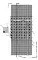
도 1은, 실시 형태 1에 있어서의 묘화 장치의 구성을 도시하는 개념도이다.
도 2는, 실시 형태 1에 있어서의 성형 애퍼처 어레이 기판의 구성을 도시하는 개념도이다.
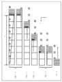
도 3은, 실시 형태 1에 있어서의 블랭킹 애퍼처 어레이 기구의 구성을 도시하는 단면도이다.
도 4는, 실시 형태 1에 있어서의 묘화 동작의 일례를 설명하기 위한 개념도이다.
도 5는, 실시 형태 1에 있어서의 멀티 빔의 조사 영역과 묘화 대상 화소의 일례를 도시하는 도면이다.
도 6은, 실시 형태 1에 있어서의 멀티 빔의 묘화 방법의 일례를 설명하기 위한 도면이다.
도 7은, 실시 형태 1에 있어서의 묘화 방법의 주요부 공정을 도시하는 흐름도이다.
도 8a는, 실시 형태 1에 있어서의 빔의 위치 어긋남과 위치 어긋남 주기성을 설명하기 위한 도면이다.
도 8b는, 실시 형태 1에 있어서의 빔의 위치 어긋남과 위치 어긋남 주기성을 설명하기 위한 도면이다.
도 9는, 실시 형태 1의 비교예에 있어서의 빔 조사 위치와 위치 어긋남 보정을 행하는 경우의 도즈 분배율의 일례를 도시하는 도면이다.
도 10은, 실시 형태 1의 비교예에 있어서의 빔 조사 위치와 위치 어긋남 보정을 행하는 경우의 도즈 분배율의 다른 일례를 도시하는 도면이다.
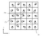
도 11은, 실시 형태 1에 있어서의 제어 그리트와 실제의 빔 조사 위치의 일례를 도시하는 도면이다.
도 12는, 실시 형태 1에 있어서의 제한 영역의 일례를 도시하는 도면이다.
도 13은, 실시 형태 1에 있어서의 제어 그리트와 실제의 빔 조사 위치와 빔의 조합의 일례를 도시하는 도면이다.
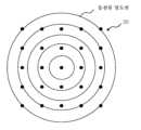
도 14는, 실시 형태 1에 있어서의 전류 밀도 분포의 일례를 도시하는 도면이다.
도 15는, 실시 형태 1에 있어서의 위치 어긋남 보정에 수반하는 최대 변조율과 최대 위치 어긋남양의 관계의 시뮬레이션 결과의 일례를 도시하는 도면이다.
도 16은, 실시 형태 1에 있어서의 반복 연산 처리부의 내부 구성의 일례를 도시하는 블록도이다.1 is a conceptual diagram showing the configuration of a drawing device in
FIG. 2 is a conceptual diagram showing the configuration of the molded aperture array substrate in
FIG. 3 is a cross-sectional view showing the configuration of the blanking aperture array mechanism in
FIG. 4 is a conceptual diagram for explaining an example of a drawing operation in
FIG. 5 is a diagram showing an example of a multi-beam irradiation area and a drawing target pixel in
FIG. 6 is a diagram for explaining an example of the multi-beam drawing method in
Fig. 7 is a flowchart showing the main steps of the drawing method in
FIG. 8A is a diagram for explaining the beam positional shift and positional shift periodicity in
FIG. 8B is a diagram for explaining the positional shift and positional shift periodicity of the beam in
FIG. 9 is a diagram showing an example of the beam irradiation position and the dose distribution ratio when position misalignment correction is performed in the comparative example of
FIG. 10 is a diagram showing another example of the beam irradiation position in the comparative example of
FIG. 11 is a diagram showing an example of the control grid and the actual beam irradiation position in
FIG. 12 is a diagram showing an example of a restricted area in
FIG. 13 is a diagram showing an example of a combination of a control grit and an actual beam irradiation position and beam in
FIG. 14 is a diagram showing an example of current density distribution in
FIG. 15 is a diagram showing an example of a simulation result of the relationship between the maximum modulation rate and the maximum amount of position misalignment accompanying position misalignment correction in
Fig. 16 is a block diagram showing an example of the internal configuration of the iterative operation processing unit in
이하, 실시 형태에서는, 하전 입자 빔의 일례로서, 전자 빔을 사용한 구성에 대하여 설명한다. 단, 하전 입자 빔은, 전자 빔에 한정되는 것은 아니고, 이온 빔 등의 하전 입자를 사용한 빔이어도 상관없다.Hereinafter, in the embodiment, a configuration using an electron beam as an example of a charged particle beam will be described. However, the charged particle beam is not limited to an electron beam, and may be a beam using charged particles such as an ion beam.
[실시 형태 1][Embodiment 1]
도 1은, 실시 형태 1에 있어서의 묘화 장치의 구성을 도시하는 개념도이다. 도 1에 있어서, 묘화 장치(100)는, 묘화 기구(150)와 제어계 회로(160)를 구비하고 있다. 묘화 장치(100)는, 멀티 하전 입자 빔 묘화 장치의 일례이다. 묘화 기구(150)는, 전자 경통(102)(멀티 전자 빔 칼럼)과 묘화실(103)을 구비하고 있다. 전자 경통(102) 내에는, 전자총(201), 조명 렌즈(202), 성형 애퍼처 어레이 기판(203), 블랭킹 애퍼처 어레이 기구(204), 축소 렌즈(205), 제한 애퍼처 기판(206), 대물 렌즈(207), 편향기(208) 및 편향기(209)가 배치되어 있다. 묘화실(103) 내에는, XY 스테이지(105)가 배치된다. XY 스테이지(105) 상에는, 묘화 시에는 묘화 대상 기판이 되는 레지스트가 도포된 마스크 블랭크스 등의 시료(101)가 배치된다. 시료(101)에는, 반도체 장치를 제조할 때의 노광용 마스크, 혹은, 반도체 장치가 제조되는 반도체 기판(실리콘 웨이퍼) 등이 포함된다. XY 스테이지(105) 상에는, 또한, XY 스테이지(105)의 위치 측정용의 미러(210)가 배치된다. XY 스테이지(105) 상에는, 또한, 패러데이 컵(106)이 배치된다.1 is a conceptual diagram showing the configuration of a drawing device in
제어계 회로(160)는, 제어 계산기(110), 메모리(112), 편향 제어 회로(130), 디지털·아날로그 변환(DAC) 앰프 유닛(132, 134), 스테이지 위치 검출기(139) 및 자기 디스크 장치 등의 기억 장치(140, 142, 144)를 갖고 있다. 제어 계산기(110), 메모리(112), 편향 제어 회로(130), DAC 앰프 유닛(132, 134), 스테이지 위치 검출기(139) 및 기억 장치(140, 142, 144)는, 도시하지 않은 버스를 통해 서로 접속되어 있다. 편향 제어 회로(130)에는, DAC 앰프 유닛(132, 134) 및 블랭킹 애퍼처 어레이 기구(204)가 접속되어 있다. DAC 앰프 유닛(132)의 출력은, 편향기(209)에 접속된다. DAC 앰프 유닛(134)의 출력은, 편향기(208)에 접속된다. 편향기(208)는, 4극 이상의 전극에 의해 구성되고, 전극마다 DAC 앰프(134)를 통해 편향 제어 회로(130)에 의해 제어된다. 편향기(209)는, 4극 이상의 전극에 의해 구성되고, 전극마다 DAC 앰프(132)를 통해 편향 제어 회로(130)에 의해 제어된다. 스테이지 위치 검출기(139)는, 레이저광을 XY 스테이지(105) 상의 미러(210)에 조사하고, 미러(210)로부터의 반사광을 수광한다. 그리고, 이러한 반사광의 정보를 사용한 레이저 간섭의 원리를 이용하여 XY 스테이지(105)의 위치를 측정한다.The control circuit 160 includes a control calculator 110, a memory 112, a deflection control circuit 130, a digital-to-analog conversion (DAC) amplifier unit 132, 134, a stage position detector 139, and a magnetic disk device. It has memory devices 140, 142, 144, etc. The control calculator 110, memory 112, deflection control circuit 130, DAC amplifier units 132 and 134, stage position detector 139 and memory devices 140, 142 and 144 use buses not shown. are connected to each other through To the deflection control circuit 130, DAC amplifier units 132 and 134 and a blanking
제어 계산기(110) 내에는, 빔 위치 어긋남 맵 작성부(50), 특정부(52), 영역 제한부(54), 설정부(56), 도즈 분배율 산출부(58), 전류 밀도 보정부(60), 조합 선택부(62), 반복 연산 처리부(64), 래스터라이즈부(66), 도즈 맵 작성부(68), 도즈 보정부(70), 조사 시간 연산부(72) 및 묘화 제어부(74)가 배치되어 있다. 빔 위치 어긋남 맵 작성부(50), 특정부(52), 영역 제한부(54), 설정부(56), 도즈 분배율 산출부(58), 전류 밀도 보정부(60), 조합 선택부(62), 반복 연산 처리부(64), 래스터라이즈부(66), 도즈 맵 작성부(68), 도즈 보정부(70), 조사 시간 연산부(72) 및 묘화 제어부(74)와 같은 각 「~부」는, 처리 회로를 갖는다. 이러한 처리 회로는, 예를 들어 전기 회로, 컴퓨터, 프로세서, 회로 기판, 양자 회로, 혹은, 반도체 장치를 포함한다. 각 「~부」는, 공통되는 처리 회로(동일한 처리 회로)를 사용해도 되고, 혹은 다른 처리 회로(별도의 처리 회로)를 사용해도 된다. 빔 위치 어긋남 맵 작성부(50), 특정부(52), 영역 제한부(54), 설정부(56), 도즈 분배율 산출부(58), 전류 밀도 보정부(60), 조합 선택부(62), 반복 연산 처리부(64), 래스터라이즈부(66), 도즈 맵 작성부(68), 도즈 보정부(70), 조사 시간 연산부(72) 및 묘화 제어부(74)에 입출력되는 정보 및 연산 중의 정보는 메모리(112)에 그때마다 저장된다.In the control calculator 110, there is a beam position misalignment map creation unit 50, a specification unit 52, an area limitation unit 54, a setting unit 56, a dose distribution ratio calculation unit 58, and a current density correction unit ( 60), combination selection unit 62, iterative
또한, 묘화 장치(100)의 외부로부터 묘화 데이터가 입력되어, 기억 장치(140)에 저장된다. 묘화 데이터에는, 통상, 묘화하기 위한 복수의 도형 패턴의 정보가 정의된다. 구체적으로는, 도형 패턴마다, 도형 코드, 좌표 및 사이즈 등이 정의된다.Additionally, drawing data is input from outside the drawing device 100 and stored in the storage device 140. In the drawing data, information on a plurality of graphic patterns for drawing is usually defined. Specifically, for each figure pattern, figure code, coordinates, size, etc. are defined.
여기서, 도 1에서는, 실시 형태 1을 설명함에 있어서 필요한 구성을 기재하고 있다. 묘화 장치(100)에 있어서, 통상, 필요한 그 밖의 구성을 구비하고 있어도 상관없다.Here, FIG. 1 describes the configuration necessary for explaining
도 2는, 실시 형태 1에 있어서의 성형 애퍼처 어레이 기판의 구성을 도시하는 개념도이다. 도 2에 있어서, 성형 애퍼처 어레이 기판(203)에는, 세로(y 방향) p열×가로(x 방향) q열(p, q≥2)의 구멍(개구부)(22)이 소정의 배열 피치로 매트릭스상으로 형성되어 있다. 도 2에서는, 예를 들어 종횡(x, y 방향)으로 512×512열의 구멍(22)이 형성된다. 각 구멍(22)은, 모두 동일 치수 형상의 직사각형으로 형성된다. 혹은, 동일한 직경의 원형이어도 상관없다. 성형 애퍼처 어레이 기판(203)(빔 형성 기구)은, 멀티 빔(20)을 형성한다. 구체적으로는, 이들의 복수의 구멍(22)을 전자 빔(200)의 일부가 각각 통과함으로써, 멀티 빔(20)이 형성되게 된다. 또한, 구멍(22)의 배열 방법은, 도 2와 같이, 종횡이 격자상으로 배치되는 경우에 한정되는 것은 아니다. 예를 들어, 세로 방향(y 방향) k단째의 열과, k+1단째의 열의 구멍끼리가, 가로 방향(x 방향)으로 치수 a만큼 어긋나서 배치되어도 된다. 마찬가지로, 세로 방향(y 방향) k+1단째의 열과, k+2단째의 열의 구멍끼리가, 가로 방향(x 방향)으로 치수 b만큼 어긋나서 배치되어도 된다.FIG. 2 is a conceptual diagram showing the configuration of the molded aperture array substrate in
도 3은, 실시 형태 1에 있어서의 블랭킹 애퍼처 어레이 기구의 구성을 도시하는 단면도이다. 블랭킹 애퍼처 어레이 기구(204)는, 도 3에 도시하는 바와 같이, 지지대(33) 상에 실리콘 등을 포함하는 반도체 기판(31)이 배치된다. 기판(31)의 중앙부는, 예를 들어 이면측으로부터 깍여져, 얇은 막 두께 h의 멤브레인 영역(330)(제1 영역)으로 가공되어 있다. 멤브레인 영역(330)을 둘러싸는 주위는, 두꺼운 막 두께 H의 외주 영역(332)(제2 영역)이 된다. 멤브레인 영역(330)의 상면과 외주 영역(332)의 상면은, 동일한 높이 위치, 혹은, 실질적으로 동일한 높이 위치가 되도록 형성된다. 기판(31)은, 외주 영역(332)의 이면에서 지지대(33) 상에 보유 지지된다. 지지대(33)의 중앙부는 개구하고 있고, 멤브레인 영역(330)의 위치는, 지지대(33)가 개구한 영역에 위치하고 있다.FIG. 3 is a cross-sectional view showing the configuration of the blanking aperture array mechanism in
멤브레인 영역(330)에는, 도 2에 도시한 성형 애퍼처 어레이 기판(203)의 각 구멍(22)에 대응하는 위치에 멀티 빔(20)의 각각의 빔의 통과용의 통과 구멍(25)(개구부)이 개구된다. 바꿔 말하면, 기판(31)의 멤브레인 영역(330)에는, 전자선을 사용한 멀티 빔(20)의 각각 대응하는 빔이 통과하는 복수의 통과 구멍(25)이 어레이상으로 형성된다. 그리고, 기판(31)의 멤브레인 영역(330) 상이며, 복수의 통과 구멍(25) 중 대응하는 통과 구멍(25)을 사이에 두고 대향하는 위치에 2개의 전극을 갖는 복수의 전극쌍이 각각 배치된다. 구체적으로는, 멤브레인 영역(330) 상에, 도 3에 도시하는 바와 같이, 각 통과 구멍(25)의 근방 위치에 해당하는 통과 구멍(25)을 사이에 두고 블랭킹 편향용의 제어 전극(24)과 대향 전극(26)의 조(블랭커: 블랭킹 편향기)가 각각 배치된다. 또한, 기판(31) 내부이며 멤브레인 영역(330) 상의 각 통과 구멍(25)의 근방에는, 각 통과 구멍(25)용의 제어 전극(24)에 편향 전압을 인가하는 제어 회로(41)(로직 회로)가 배치된다. 각 빔용의 대향 전극(26)은, 그라운드 접속된다.In the
제어 회로(41) 내에는, 도시하지 않은 앰프(스위칭 회로의 일례)가 배치된다. 앰프의 일례로서, CMOS(Complementary MOS) 인버터 회로가 배치된다. 그리고, CMOS 인버터 회로는 정의 전위(Vdd: 블랭킹 전위: 제1 전위)(예를 들어, 5V)(제1 전위)와 그라운드 전위(GND: 제2 전위)에 접속된다. CMOS 인버터 회로의 출력선(OUT)은 제어 전극(24)에 접속된다. 한편, 대향 전극(26)은, 그라운드 전위가 인가 된다. 그리고, 블랭킹 전위와 그라운드 전위가 전환 가능하게 인가되는 복수의 제어 전극(24)이, 기판(31) 상이며, 복수의 통과 구멍(25)의 각각 대응하는 통과 구멍(25)을 사이에 두고 복수의 대향 전극(26)의 각각 대응하는 대향 전극(26)과 대향하는 위치에 배치된다.In the
CMOS 인버터 회로의 입력(IN)에는, 역치 전압보다도 낮아지는 L(low) 전위(예를 들어 그라운드 전위)와, 역치 전압 이상이 되는 H(high) 전위(예를 들어, 1.5V)의 어느 것이 제어 신호로서 인가된다. 실시 형태 1에서는, CMOS 인버터 회로의 입력(IN)에 L 전위가 인가되는 상태에서는, CMOS 인버터 회로의 출력(OUT)은 정전위(Vdd)가 되고, 대향 전극(26)의 그라운드 전위와의 전위차에 의한 전계에 의해 멀티 빔(20) 중의 대응하는 1개를 편향시키고, 제한 애퍼처 기판(206)으로 차폐함으로써 빔 OFF가 되도록 제어한다. 한편, CMOS 인버터 회로의 입력(IN)에 H 전위가 인가 되는 상태(액티브 상태)에서는, CMOS 인버터 회로의 출력(OUT)은 그라운드 전위가 되고, 대향 전극(26)의 그라운드 전위와의 전위차가 없어져 멀티 빔(20) 중의 대응하는 1개를 편향시키지 않으므로 제한 애퍼처 기판(206)을 통과함으로써 빔 ON이 되도록 제어한다.The input (IN) of the CMOS inverter circuit is either an L (low) potential that is lower than the threshold voltage (e.g., ground potential) or an H (high) potential that is higher than the threshold voltage (e.g., 1.5 V). It is applied as a control signal. In
각 통과 구멍을 통과하는 멀티 빔(20) 중의 대응하는 1개의 전자 빔은, 각각 독립적으로 쌍이 되는 2개의 제어 전극(24)과 대향 전극(26)에 인가되는 전압에 의해 편향된다. 이러한 편향에 의해 블랭킹 제어된다. 구체적으로는, 제어 전극(24)과 대향 전극(26)의 조는, 각각 대응하는 스위칭 회로가 되는 CMOS 인버터 회로에 의해 전환되는 전위에 의해 멀티 빔(20)의 대응 빔을 각각 개별로 블랭킹 편향시킨다. 이와 같이, 복수의 블랭커가, 성형 애퍼처 어레이 기판(203)의 복수의 구멍(22)(개구부)을 통과한 멀티 빔(20) 중, 각각 대응하는 빔의 블랭킹 편향을 행한다.One corresponding electron beam among the multi-beams 20 passing through each passage hole is deflected by a voltage applied to the two independently paired
도 4는, 실시 형태 1에 있어서의 묘화 동작의 일례를 설명하기 위한 개념도이다. 도 4에 도시하는 바와 같이, 시료(101)의 묘화 영역(30)은, 예를 들어 y 방향을 향하여 소정의 폭으로 직사각형의 복수의 스트라이프 영역(32)으로 가상 분할된다. 먼저, XY 스테이지(105)를 이동시켜서, 제1번째의 스트라이프 영역(32)의 좌측 단부, 혹은 더 좌측의 위치에 1회의 멀티 빔(20)의 샷으로 조사 가능한 조사 영역(34)이 위치하도록 조정하고, 묘화가 개시된다. 제1번째의 스트라이프 영역(32)을 묘화할 때에는, XY 스테이지(105)를 예를 들어 -x 방향으로 이동시킴으로써, 상대적으로 x 방향으로 묘화를 진행시켜 간다. XY 스테이지(105)는 예를 들어 등속으로 연속 이동시킨다. 제1번째의 스트라이프 영역(32)의 묘화 종료 후, 스테이지 위치를 -y 방향으로 이동시켜서, 제2번째의 스트라이프 영역(32)의 우측 단부, 혹은 더 우측의 위치에 조사 영역(34)이 상대적으로 y 방향에 위치하도록 조정하고, 이번에는, XY 스테이지(105)를 예를 들어 x 방향으로 이동시킴으로써, -x 방향을 향하여 마찬가지로 묘화를 행한다. 제3번째의 스트라이프 영역(32)에서는, x 방향을 향하여 묘화하고, 제4번째의 스트라이프 영역(32)에서는, -x 방향을 향하여 묘화하는 식으로, 교호로 방향을 바꾸면서 묘화함으로써 묘화 시간을 단축할 수 있다. 단, 이러한 교호로 방향을 바꾸면서 묘화하는 경우에 한하지 않고, 각 스트라이프 영역(32)을 묘화할 때, 동일한 방향을 향하여 묘화를 진행시키도록 해도 상관없다. 1회의 샷에서는, 성형 애퍼처 어레이 기판(203)의 각 구멍(22)을 통과함으로써 형성된 멀티 빔에 의해, 최대로 성형 애퍼처 어레이 기판(203)에 형성된 복수의 구멍(22)과 동일 수의 복수의 숏 패턴이 한번에 형성된다. 또한, 도 4의 예에서는, 각 스트라이프 영역(32)을 1회씩 묘화하는 경우를 도시하고 있지만, 이것에 한정되는 것은 아니다. 동일한 영역을 복수회 묘화하는 다중 묘화를 행해도 적합하다. 다중 묘화를 행하는 경우에는, 위치를 어긋나게 하면서 각 패스의 스트라이프 영역(32)을 설정하면 적합하다.FIG. 4 is a conceptual diagram for explaining an example of a drawing operation in
도 5는, 실시 형태 1에 있어서의 멀티 빔의 조사 영역과 묘화 대상 화소의 일례를 도시하는 도면이다. 도 5에 있어서, 스트라이프 영역(32)에는, 예를 들어 시료(101)면 상에 있어서의 멀티 빔(20)의 빔 사이즈 피치로 격자상으로 배열되는 복수의 제어 그리드(27)(설계 그리드)가 설정된다. 이 제어 그리드(27)는, 예를 들어 10㎚ 정도의 배열 피치로 하면 적합하다. 이러한 복수의 제어 그리드(27)가, 멀티 빔(20)의 설계 상의 조사 위치가 된다. 제어 그리드(27)의 배열 피치는 빔 사이즈에 한정되는 것은 아니고, 빔 사이즈와는 관계없이 편향기(209)의 편향 위치로서 제어 가능한 임의의 크기로 구성되는 것이어도 상관없다. 그리고, 각 제어 그리드(27)를 중심으로 한, 제어 그리드(27)의 배열 피치와 동 사이즈로 메쉬상으로 가상 분할된 복수의 화소(36)가 설정된다. 각 화소(36)는, 멀티 빔의 1개의 빔당의 조사 단위 영역이 된다. 도 5의 예에서는, 시료(101)의 묘화 영역이, 예를 들어 y 방향으로, 1회의 멀티 빔(20)(빔 어레이)의 조사로 조사 가능한 조사 영역(34)(묘화 필드)의 사이즈와 실질적으로 동일한 폭 사이즈로 복수의 스트라이프 영역(32)으로 분할된 경우를 도시하고 있다. 조사 영역(34)의 x 방향 사이즈는, 멀티 빔(20)의 x 방향의 빔 간 피치에 x 방향의 빔수를 곱한 값으로 정의할 수 있다. 조사 영역(34)의 y 방향 사이즈는, 멀티 빔(20)의 y 방향의 빔 간 피치에 y 방향의 빔수를 곱한 값으로 정의할 수 있다. 또한, 스트라이프 영역(32)의 폭은, 이것에 한정되는 것은 아니다. 조사 영역(34)의 n배(n은 1 이상의 정수)의 사이즈이면 적합하다. 도 5의 예에서는, 예를 들어 512×512열의 멀티 빔의 도시를 8×8열의 멀티 빔으로 생략하여 도시하고 있다. 그리고, 조사 영역(34) 내에, 1회의 멀티 빔(20)의 샷으로 조사 가능한 복수의 화소(28)(빔의 묘화 위치)가 도시되어 있다. 바꿔 말하면, 인접하는 화소(28) 사이의 피치가 설계 상의 멀티 빔의 각 빔 간의 피치가 된다. 도 5의 예에서는, 빔 간 피치로 둘러싸인 영역으로 1개의 서브 조사 영역(29)을 구성한다. 도 5의 예에서는, 각 서브 조사 영역(29)은, 4×4 화소로 구성되는 경우를 도시하고 있다.FIG. 5 is a diagram showing an example of a multi-beam irradiation area and a drawing target pixel in
도 6은, 실시 형태 1에 있어서의 멀티 빔의 묘화 방법의 일례를 설명하기 위한 도면이다. 도 6에서는, 도 5에서 도시한 스트라이프 영역(32)을 묘화하는 멀티 빔 중, y 방향 k단째의 좌표 (1, 3), (2, 3), (3, 3), …, (512, 3)의 각 빔으로 묘화하는 서브 조사 영역(29)의 일부를 도시하고 있다. 도 6의 예에서는, 예를 들어 XY 스테이지(105)가 8 빔 피치분의 거리를 이동하는 동안에 4개의 화소를 묘화(노광)하는 경우를 도시하고 있다. 이러한 4개의 화소를 묘화(노광)하는 동안, 조사 영역(34)이 XY 스테이지(105)의 이동에 의해 시료(101)와의 상대 위치가 어긋나지 않도록, 편향기(208)에 의해 멀티 빔(20) 전체를 일괄 편향시킨다. 이에 의해, 조사 영역(34)을 XY 스테이지(105)의 이동에 추종시킨다. 바꿔 말하면, 트래킹 제어가 행해진다. 도 6의 예에서는, 8 빔 피치분의 거리를 이동하는 동안에 4개의 화소를 묘화(노광)함으로써 1회의 트래킹 사이클을 실시하는 경우를 도시하고 있다.FIG. 6 is a diagram for explaining an example of the multi-beam drawing method in
구체적으로는, 각 샷에 있어서, 설정된 최대 조사 시간 내의 각각의 제어 그리드(27)에 대응하는 조사 시간(묘화 시간, 혹은 노광 시간) 빔을 조사한다. 구체적으로는, 각 제어 그리드(27)에 멀티 빔(20) 중 ON 빔의 각각 대응하는 빔을 조사한다. 그리고, 최대 조사 시간에 DAC 앰프의 정정 시간을 가산한 샷 사이클 시간 Ttr마다, 편향기(209)에 의한 일괄 편향에 의해 각 빔의 조사 위치를 다음의 샷 위치로 이동한다.Specifically, in each shot, a beam with an irradiation time (drawing time or exposure time) corresponding to each
그리고, 도 6의 예에서는 4샷 종료한 시점에서, DAC 앰프 유닛(134)은, 트래킹 제어용의 빔 편향을 리셋한다. 이에 의해, 트래킹 위치를 트래킹 제어가 개시된 트래킹 개시 위치로 복귀한다.And in the example of FIG. 6, at the end of 4 shots, the DAC amplifier unit 134 resets the beam deflection for tracking control. Thereby, the tracking position is returned to the tracking start position where tracking control was started.
또한, 각 서브 조사 영역(29)의 우측으로부터 1번째의 화소 열의 묘화는 종료되어 있다. 따라서, 트래킹 리셋한 후에, 다음번의 트래킹 사이클에 있어서 먼저 편향기(209)는, 각 서브 조사 영역(29) 아래로부터 1단째 또한 우측으로부터 2번째의 화소의 제어 그리드(27)에 각각 대응하는 빔의 조사 위치를 맞추(시프트하)도록 편향시킨다. 이러한 동작을 반복함으로써, 모든 화소의 묘화가 행해진다. 서브 조사 영역(29)이 n×n 화소로 구성되는 경우에, n회의 트래킹 동작으로 각각 다른 빔에 의해 n 화소씩 묘화된다. 이에 의해, 1개의 n×n 화소의 영역 내의 모든 화소가 묘화된다. 멀티 빔의 조사 영역 내의 다른 n×n 화소의 영역에 대해서도 동일 시기에 마찬가지의 동작이 실시되고, 마찬가지로 묘화된다.Additionally, drawing of the first pixel row from the right of each
다음으로 묘화 장치(100)에 있어서의 묘화 기구(150)의 동작에 대하여 설명한다. 전자총(201)(방출원)으로부터 방출된 전자 빔(200)은, 조명 렌즈(202)에 의해 성형 애퍼처 어레이 기판(203) 전체를 조명한다. 성형 애퍼처 어레이 기판(203)에는, 직사각형의 복수의 구멍(22)(개구부)이 형성된다. 그리고, 전자 빔(200)은, 모든 복수의 구멍(22)이 포함되는 영역을 조명한다. 복수의 구멍(22)의 위치에 조사된 전자 빔(200)의 각 일부가, 이러한 성형 애퍼처 어레이 기판(203)의 복수의 구멍(22)을 각각 통과한다. 이에 의해, 예를 들어 직사각형 형상의 복수의 전자 빔(멀티 빔(20))이 형성된다. 이러한 멀티 빔(20)은, 블랭킹 애퍼처 어레이 기구(204)의 각각 대응하는 블랭커(제1 편향기: 개별 블랭킹 기구) 내를 통과한다. 이러한 블랭커는, 각각, 개별로 통과하는 전자 빔을 편향시킨다(블랭킹 편향을 행한다).Next, the operation of the drawing mechanism 150 in the drawing device 100 will be described. The electron beam 200 emitted from the electron gun 201 (emission source) illuminates the entire shaped
블랭킹 애퍼처 어레이 기구(204)를 통과한 멀티 빔(20)은, 축소 렌즈(205)에 의해, 축소되고, 제한 애퍼처 기판(206)에 형성된 중심의 구멍을 향하여 진행한다. 여기서, 멀티 빔(20) 중, 블랭킹 애퍼처 어레이 기구(204)의 블랭커에 의해 편향된 전자 빔은, 제한 애퍼처 기판(206)의 중심 구멍으로부터 위치가 벗어나, 제한 애퍼처 기판(206)에 의해 차폐된다. 한편, 블랭킹 애퍼처 어레이 기구(204)의 블랭커에 의해 편향되지 않은 전자 빔은, 도 1에 도시하는 바와 같이 제한 애퍼처 기판(206)의 중심 구멍을 통과한다. 이러한 개별 블랭킹 기구(47)의 ON/OFF에 의해, 블랭킹 제어가 행해지고, 빔의 ON/OFF가 제어된다. 이와 같이, 제한 애퍼처 기판(206)은, 개별 블랭킹 기구(47)에 의해 빔 OFF의 상태가 되도록 편향된 각 빔을 차폐한다. 그리고, 빔마다, 빔 ON이 되고 나서 빔 OFF가 될 때까지 형성된, 제한 애퍼처 기판(206)을 통과한 빔에 의해, 1회분의 샷 빔이 형성된다. 제한 애퍼처 기판(206)을 통과한 멀티 빔(20)은, 대물 렌즈(207)에 의해 초점이 맞춰져, 원하는 축소율의 패턴상이 되고, 편향기(208, 209)에 의해, 제한 애퍼처 기판(206)을 통과한 각 빔(통과한 멀티 빔(20) 전체)이 동일 방향으로 일괄하여 편향되고, 각 빔의 시료(101) 상의 각각의 조사 위치에 조사된다. 한번에 조사되는 멀티 빔(20)은, 이상적으로는 성형 애퍼처 어레이 기판(203)의 복수의 구멍(22)의 배열 피치에 상술한 원하는 축소율을 곱한 피치로 배열하게 된다.The multi-beam 20 that has passed through the blanking
상술한 바와 같이, 멀티 빔 묘화에서는, 광학계의 특성상, 노광 필드에 변형이 생기고, 이러한 변형 등에 의해, 멀티 빔(20)의 개개의 빔의 조사 위치가 이상 그리드로부터 어긋나 버린다. 그러나, 멀티 빔(20)의 개개의 빔을 개별로 편향시키는 것은 어려우므로 개개의 빔 시료(101)면 상의 위치를 개별로 제어하는 것은 곤란하다. 그 때문에, 각 빔의 위치 어긋남을 도즈 변조에 의해 보정하는 것이 행해진다. 그러나, 도즈 변조 후의 각 빔의 도즈 변조율 중의 최대 변조율이 커져 버리는 경우가 있다. 최대 변조율이 커지는 것에 수반하여, 최대 조사 시간이 길어져 버린다. 그래서, 실시 형태 1에서는, 제어 그리드(27)에 가장 가까이에 조사되는 최근접 빔에 착안하고, 이러한 최근접 빔에 대한 도즈 분배량을 높게 함으로써, 최대 변조율을 저감한다. 이하, 구체적으로 설명한다.As described above, in multi-beam writing, due to the characteristics of the optical system, deformation occurs in the exposure field, and due to this deformation, the irradiation position of each beam of the multi-beam 20 deviates from the ideal grid. However, since it is difficult to individually deflect each beam of the multi-beam 20, it is difficult to individually control the position of each beam on the
도 7은, 실시 형태 1에 있어서의 묘화 방법의 주요부 공정을 도시하는 흐름도이다. 도 7에 있어서, 실시 형태 1에 있어서의 묘화 방법은, 빔 위치 어긋남양 측정 공정(S102)과, 제1 근접 빔 특정 공정(S104)과, 영역 제한 공정(S106)과, 조합 설정 공정(S108)과, 도즈 분배율 산출 공정(S110)과, 전류 밀도 보정 공정(S112)과, 조합 선택 공정(S114)과, 반복 연산 처리 공정(S118)과, 도즈양 연산 공정(S130)과, 도즈 보정 공정(S134)과, 조사 시간 연산 공정(S140)과, 묘화 공정(S142)이라고 하는 일련의 공정을 실시한다.Fig. 7 is a flowchart showing the main steps of the drawing method in
빔 위치 어긋남양 측정 공정(S102)과, 제1 근접 빔 특정 공정(S104)과, 영역 제한 공정(S106)과, 조합 설정 공정(S108)과, 도즈 분배율 산출 공정(S110)과, 전류 밀도 보정 공정(S112)과, 조합 선택 공정(S114)과, 반복 연산 처리 공정(S118)의 각 공정은, 묘화 처리를 개시하기 전의 전처리로서 실시된다.Beam position misalignment measurement process (S102), first proximity beam specification process (S104), area limitation process (S106), combination setting process (S108), dose distribution ratio calculation process (S110), and current density correction Each process of the process S112, the combination selection process S114, and the iterative operation processing process S118 is performed as preprocessing before starting the drawing process.
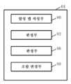
또한, 실시 형태 1에 있어서의 묘화 방법에서는, 반복 연산 처리 공정(S118)을 실시한 쪽이 적합하지만, 생략해도 상관없다. 반복 연산 처리 공정(S118)을 생략하는 경우, 도 1에 있어서 제어 계산기(110) 내에 배치되는 반복 연산 처리부(64)를 생략해도 상관없다. 반대로, 반복 연산 처리 공정(S118)을 실시하는 경우, 그 내부 공정으로서, 합성 맵 작성 공정(S120)과, 판정 공정(S122)과, 조합 갱신 공정(S124)과, 조합 변경 공정(S125)과, 판정 공정(S126)이라고 하는 일련의 공정을 실시한다.In addition, in the drawing method in
또한, 실시 형태 1에 있어서의 묘화 방법에서는, 전류 밀도 보정 공정(S112)을 실시한 쪽이 적합하지만, 생략해도 상관없다. 전류 밀도 보정 공정(S112)을 생략하는 경우, 도 1에 있어서 제어 계산기(110) 내에 배치되는 전류 밀도 보정부(60)를 생략해도 상관없다.In addition, in the drawing method in
빔 위치 어긋남양 측정 공정(S102)으로서, 묘화 장치(100)는, 멀티 빔(20)의 각 빔의 시료(101) 면 상의 조사 위치가, 대응하는 제어 그리드(27)로부터 어긋나는 위치 어긋남양을 측정한다.In the beam position misalignment amount measurement process (S102), the drawing device 100 determines the position misalignment amount by which the irradiation position of each beam of the multi-beam 20 on the surface of the
도 8a와 도 8b는, 실시 형태 1에 있어서의 빔의 위치 어긋남과 위치 어긋남 주기성을 설명하기 위한 도면이다. 멀티 빔(20)에서는, 도 8a에 도시하는 바와 같이, 광학계의 특성상, 노광 필드에 변형이 생기고, 이러한 변형 등에 의해, 개개의 빔의 실제 조사 위치(39)가 이상 그리드인 제어 그리드(27)로부터 어긋나 버린다. 그래서, 실시 형태 1에서는, 이러한 개개의 빔 실제 조사 위치(39)의 위치 어긋남양을 측정한다. 구체적으로는, 레지스트가 도포된 평가 기판에, 멀티 빔(20)을 조사하고, 평가 기판을 현상함으로써 생성되는 레지스트 패턴의 위치를 위치 측정기로 측정한다. 이에 의해, 빔마다의 위치 어긋남양을 측정한다. 각 빔의 샷 사이즈에서는, 각 빔의 조사 위치에 있어서의 레지스트 패턴의 사이즈를 위치 측정기로 측정 곤란하면, 각 빔에서, 위치 측정기로 측정 가능한 사이즈의 도형 패턴(예를 들어 직사각형 패턴)을 묘화한다. 그리고, 도형 패턴(레지스트 패턴)의 양측의 에지 위치를 측정하여, 양쪽 에지 간의 중간 위치와 설계상의 도형 패턴의 중간 위치의 차분으로부터 대상 빔의 위치 어긋남양을 측정하면 된다. 그리고, 얻어진 각 빔의 조사 위치의 위치 어긋남양 데이터는, 묘화 장치(100)에 입력되어, 기억 장치(144)에 저장된다. 또한, 멀티 빔 묘화에서는, 스트라이프 영역(32) 내에 있어서 조사 영역(34)을 어긋나게 하면서 묘화를 진행시켜 가기 위해서, 예를 들어 도 6에 있어서 설명한 묘화 시퀀스에서는, 도 4의 하단에 도시하는 바와 같이, 스트라이프 영역(32)의 묘화 중, 조사 영역(34a 내지 34o)과 같은 방식으로 순차 조사 영역(34)의 위치가 이동한다. 그리고, 조사 영역(34)의 이동마다, 각 빔의 위치 어긋남에 주기성이 발생하게 된다. 혹은, 각 빔이, 각각 대응하는 서브 조사 영역(29) 내의 모든 화소(36)를 조사하는 묘화 시퀀스의 경우라면, 도 8b에 도시하는 바와 같이, 적어도 조사 영역(34)과 동일한 사이즈의 단위 영역(35)마다(35a, 35b, ···) 각 빔의 위치 어긋남에 주기성이 발생하게 된다. 따라서, 빔 어레이의 조사 영역(34)분의 각 빔의 위치 어긋남양을 측정하면, 측정 결과를 유용할 수 있다. 바꿔 말하면, 각 빔에 대해서, 대응하는 서브 조사 영역(29) 내의 각 화소(36)에서의 위치 어긋남양을 측정할 수 있으면 된다.FIGS. 8A and 8B are diagrams for explaining the positional shift and positional shift periodicity of the beam in
그리고, 빔 위치 어긋남 맵 작성부(50)는, 먼저, 빔 어레이 단위, 바꿔 말하면, 조사 영역(34)에 대응하는 시료면 상의 1개의 직사각형 단위 영역(35) 내의 각 화소(36)의 각 빔의 위치 어긋남양을 정의하는 빔 위치 어긋남양 맵을 작성한다. 구체적으로는, 빔 위치 어긋남 맵 작성부(54)는, 기억 장치(144)로부터 각 빔의 조사 위치의 위치 어긋남양 데이터를 읽어내고, 이러한 데이터를 맵 값으로서 빔 위치 어긋남양 맵을 작성하면 된다. 멀티 빔(20) 전체의 조사 영역(34)에 대응하는 시료면 상의 1개의 직사각형 단위 영역(35) 내의 각 화소(36)의 제어 그리드(27)를 어느 빔이 조사하는 것인지는, 예를 들어 도 6에 있어서 설명한 바와 같이, 묘화 시퀀스에 의해 결정된다. 따라서, 빔 위치 어긋남 맵 작성부(50)는, 묘화 시퀀스에 따라서 1개의 단위 영역(35) 내의 각 화소(36)의 제어 그리드(27)마다 당해 제어 그리드(27)로의 조사를 담당하는 빔을 특정하여, 당해 빔의 위치 어긋남양을 연산한다. 작성된 빔 위치 어긋남양 맵은, 기억 장치(144)에 저장해 둔다.Then, the beam position misalignment map creation unit 50 first generates each beam of each
도 9는, 실시 형태 1의 비교예에 있어서의 빔 조사 위치와 위치 어긋남 보정을 행하는 경우의 도즈 분배율의 일례를 도시하는 도면이다.FIG. 9 is a diagram showing an example of the beam irradiation position and the dose distribution ratio when position misalignment correction is performed in the comparative example of
도 10은, 실시 형태 1의 비교예에 있어서의 빔 조사 위치와 위치 어긋남 보정을 행하는 경우의 도즈 분배율의 다른 일례를 도시하는 도면이다. 도 9 및 도 10에서는, 예를 들어 5×5개의 화소(36)가 배열되는 영역을 도시하고 있다. 각 화소(36)를 어느 빔이 조사하는 것인지는 묘화 시퀀스에 의해 결정된다. 격자상으로 배열되는 제어 그리드(27)에 대하여, 각 빔의 실제 조사 위치(39)는 어긋나 버리는 경우가 많다. 도 9의 예에서는, 중심에 위치하는 화소의 제어 그리드(27a)에 원하는 도즈양을 조사하고 싶은 경우, 비교예에서는, 제어 그리드(27a)를 둘러싸는 3개의 빔에 제어 그리드(27a)에 조사 예정인 도즈양을 분배한다. 도 9의 예에서는, 예를 들어 조사 위치(39a)의 빔과 조사 위치(39b)의 빔과 조사 위치(39c)의 빔으로 도즈 분배한다. 도즈 분배량의 무게 중심이 제어 그리드(27a)의 위치가 되도록 도즈 분배율이 산출된다. 이 결과, 조사 위치(39a)의 빔은, 제어 그리드(27a)로부터의 어긋남양이 작음에도 불구하고, 도즈 분배율이 0.03이 된다. 이 결과, 제어 그리드(27a)로부터 이격된 조사 위치(39b)의 빔에 대한 도즈 분배율이 0.64가 된다. 마찬가지로, 조사 위치(39b)의 빔보다도 더 떨어진 조사 위치(39c)의 빔에 대한 도즈 분배율이 0.33이 된다. 이와 같이 하여, 각 제어 그리드(27)에 대해서, 마찬가지로, 주위의 빔에 도즈를 분배하기 위한 도즈 분배율을 산출한다.FIG. 10 is a diagram showing another example of the beam irradiation position in the comparative example of
도 10의 예에서는, 제어 그리드(27a)의 y 방향으로 인접하는 화소(36)의 제어 그리드(27b)에 대하여 도즈를 분배하는 경우의 일례를 도시하고 있다. 도 10의 예에서는, 제어 그리드(27b)를 둘러싸는, 예를 들어 조사 위치(39b)의 빔과 조사 위치(39d)의 빔과 조사 위치(39e)의 빔으로 도즈 분배한다. 제어 그리드(27a)의 경우와 마찬가지로, 도즈 분배량의 무게 중심이 제어 그리드(27b)의 위치가 되도록 도즈 분배율이 산출된다. 그 결과, 제어 그리드(27b)에 가장 가까운 조사 위치(39b)의 빔은, 도즈 분배율이 0.82가 된다. 조사 위치(39d)의 빔에 대한 도즈 분배율이 0.15가 된다. 마찬가지로, 조사 위치(39e)의 빔에 대한 도즈 분배율이 0.03이 된다. 2개의 제어 그리드(27a, 27b)에 관한 7 도즈 분배만으로, 조사 위치(39b)의 빔에 대한 도즈 분배율이 1.46(=0.64+0.82)이 된다. 그 밖의 제어 그리드(27)로부터의 조사 위치(39b)의 빔에 대한 도즈 분배율도 가산될 가능성이 높다. 이와 같이, 비교예에서는, 합계 도즈 분배율이 1을 크게 초과해 버리는 빔이 발생한다. 이 원인으로서, 제어 그리드(27a)로부터의 어긋남양이 작은 조사 위치(39a)의 빔에 대한 제어 그리드(27a)로부터의 도즈 분배율이 0.03으로 작은 것을 들 수 있다. 그래서, 실시 형태 1에서는, 각 제어 그리드(27)에 가장 가까이에 조사되는 최근접 빔에 대한 도즈 분배율을 높게 한다. 그 때문에, 이하의 공정을 실시한다.The example in FIG. 10 shows an example of distributing the dose to the
제1 근접 빔 특정 공정(S104)으로서, 특정부(52)는, 멀티 빔(20)의 설계상의 조사 위치가 되는 복수의 제어 그리드(27)의 제어 그리드(27)마다, 멀티 빔(20) 중, 대상의 제어 그리드(27)로부터 실제의 조사 위치(39)가 가장 가까운 최근접 빔(제1 빔)을 특정한다.In the first proximity beam specification process (S104), the specification unit 52 sets the multi-beam 20 for each
도 11은, 실시 형태 1에 있어서의 제어 그리트와 실제의 빔 조사 위치의 일례를 도시하는 도면이다. 도 11의 예에서는, 예를 들어 5×5개의 화소(36)가 배열되는 영역을 도시하고 있다. 각 화소(36)를 어느 빔이 조사하는 것인지는 묘화 시퀀스에 의해 결정된다. 격자상으로 배열되는 제어 그리드(27)에 대하여, 각 빔의 실제 조사 위치(39)는 어긋나 버리는 경우가 많다. 도 11의 예에서는, 도 9 및 도 10과 동일 위치 관계에 있는 제어 그리트(27)와 실제의 빔 조사 위치(39)의 일례를 도시하고 있다. 도 11에 있어서, 중심에 위치하는 화소(36)의 제어 그리드(27a)로부터 가장 가까운 최근접 빔은, 조사 위치(39a)의 빔인 것을 알 수 있다. 따라서, 특정부(52)는, 제어 그리드(27a)에 대해서, 조사 위치(39a)의 빔을 최근접 빔이라고 특정한다. 그 밖의 제어 그리드(27)에 대해서도, 마찬가지로, 최근접 빔을 특정한다.FIG. 11 is a diagram showing an example of the control grid and the actual beam irradiation position in
영역 제한 공정(S106)으로서, 영역 제한부(54)는, 제어 그리드(27)마다, 멀티 빔(20)으로부터 최근접 빔을 포함하는 2개 이상의 빔으로 구성되는 복수의 조합을 설정하기 위한 2번째의 빔(제2 빔)을 선택하기 위한 영역(제한 영역)을 제한한다.As an area limitation process (S106), the area limitation unit 54 sets, for each
도 12는, 실시 형태 1에 있어서의 제한 영역의 일례를 도시하는 도면이다. 도 12에 있어서, 제한 영역(17)은, 대상의 제어 그리드(27a)와 최근접 빔의 조사 위치(39a)를 연결하는 직선(11)에 직교함과 함께 제어 그리드(27a)를 통과하는 직선(13)에 대하여, 최근접 빔의 조사 위치(39a)와는 반대측의 영역이다.FIG. 12 is a diagram showing an example of a restricted area in
조합 설정 공정(S108)으로서, 설정부(56)(조합 설정부)는 제어 그리드(27)마다, 멀티 빔(20)으로부터 최근접 빔을 포함하는 2개 이상의 빔, 예를 들어 3개로 구성되는 복수의 조합을 설정한다.As a combination setting process (S108), the setting unit 56 (combination setting unit) is composed of two or more beams, for example three, including the nearest beam from the multi-beam 20 for each
도 13은, 실시 형태 1에 있어서의 제어 그리트와 실제의 빔 조사 위치와 빔의 조합의 일례를 도시하는 도면이다. 상술한 바와 같이, 설정부(56)는, 복수의 조합의 조합마다, 제한된 제한 영역(17) 내의 빔군 중에서 2개 이상의 빔 중의 제2번째의 빔을 선택한다. 도 13의 예에서는, 제2번째의 빔은, 직선(13)에 대하여, 조사 위치(39a)와는 반대측의 제한 영역(17)에서 선택된다. 도 13의 예에서는, 예를 들어 조사 위치(39f)의 빔이 제2번째의 빔(제2 빔)으로서 선택된다. 제2번째의 빔이, 최근접 빔에 대하여 직선(13)의 반대측에 위치함으로써, 최근접 빔의 도즈 분배율을 높일 수 있다.FIG. 13 is a diagram showing an example of a combination of a control grit and an actual beam irradiation position and beam in
설정부(56)는, 조합을 구성하는 2개 이상의 빔의 제3번째 이후의 빔을 선택한다. 제3번째 이후의 빔에 대해서는, 조합을 구성하는 3개 이상의 빔으로 대상의 제어 그리드(27)를 둘러쌀 수 있는 위치이면 된다. 도 13의 예에서는, 조사 위치(39g)의 빔이 제3번째의 빔(제3 빔)으로서 선택된다. 이와 같이, 도 13에서는, 제어 그리드(27a)에 대하여 설정되는 복수의 조합 중의 1개가, 조사 위치(39a)의 빔과 조사 위치(39f)의 빔과 조사 위치(39g)의 빔으로 구성되는 경우를 도시하고 있다. 그 밖의 조합에 대해서는, 도시를 생략하고 있다. 여기에서는, 3개의 빔으로 조합을 구성하는 경우를 설명하지만, 3개 이상의 빔이면 된다.The setting unit 56 selects the third and subsequent beams of the two or more beams constituting the combination. For the third and subsequent beams, any position that can surround the
도즈 분배율 산출 공정(S110)으로서, 도즈 분배율 산출부(58)(분배율 산출부)는, 제어 그리드(27)마다, 또한, 복수의 조합의 조합마다, 당해 조합을 구성하는 2개 이상의 빔에, 분배 후의 각 분배 도즈양의 총합이 당해 제어 그리드(27)에 조사될 예정의 도즈양과 동등해지도록, 예를 들어 일치하도록 당해 제어 그리드(27)에 조사될 예정의 도즈양을 분배하기 위한, 당해 조합을 구성하는 2개 이상의 빔의 각 빔에 대한 도즈 분배율을 산출한다. 도즈 분배율 산출부(58)는, 2개 이상의 빔에 분배 후의 각 분배 도즈양의 무게 중심과 대응하는 제어 그리드(27)의 어긋남이 허용 범위 Th 내가 되도록 2개 이상의 빔의 각 빔에 대한 도즈 분배율을 산출한다. 실시 형태 1에 있어서, 무게 중심이 제어 그리드(27)와 완전 일치하는 것이 바람직하지만, 이것에 한정되는 것은 아니다. 무게 중심과 제어 그리드(27)의 어긋남이 허용 범위 Th 내이면 된다. 예를 들어, 화소 사이즈의 1/5 내이면 적합하다. 더욱 바람직하게는 화소 사이즈의 1/10 내이면 된다. 대상의 제어 그리드(27)의 규격화된 도즈양 d(i)를 d(i)=1로 한 경우에, 최근접 빔과 제2번째의 빔과 제3번째의 빔에 대한 도즈 분배율 d1, d2, d3은, 임의의 기준 위치로부터 대상의 제어 그리드(27)에 대한 벡터 r과 각 빔에 대한 벡터 r1, r2, r3을 사용하여 이하의 식 (1-1) 및 식 (1-2)를 충족하는 값으로서 구할 수 있다. i는 인덱스를 나타낸다.In the dose distribution ratio calculation process (S110), the dose distribution ratio calculation unit 58 (distribution ratio calculation unit) applies to the two or more beams constituting the combination for each
Th=0의 경우의 도즈 분배율 d1, d2, d3 외에, Th=0이 아닌 경우의 도즈 분배율 d1, d2, d3가 산출될 수 있지만, 이들 중 최근접 빔의 도즈 분배율 d1이 가능한 한 커지는 값을 채용하는 것이 바람직하다.In addition to the dose distribution ratios d1 , d2 , and d3 in the case of Th = 0, the dose distribution ratios d1 , d2 , and d3 in the case of Th = 0 can be calculated, but among these, the dose distribution ratio d of the nearest beam is It is desirable to adopt a value that makes1 as large as possible.
전류 밀도 보정 공정(S112)으로서, 전류 밀도 보정부(60)(가중치 부여 처리부)는, 제어 그리드(27)마다, 또한, 복수의 조합의 조합마다, 2개 이상의 빔에 대한 도즈 분배율에, 전류 밀도의 어긋남을 보정하는 전류 밀도 보정값을 사용하여 가중치 부여된 도즈 분배율을 산출한다.As a current density correction process (S112), the current density correction unit 60 (weighting processing unit) calculates the current for each
도 14는, 실시 형태 1에 있어서의 전류 밀도 분포의 일례를 도시하는 도면이다. 도 14의 예에서는, 예를 들어 5×5개의 멀티 빔(20)을 사용하는 경우를 도시하고 있다. 도 14의 예에 도시하는 바와 같이, 전류 밀도는 일반적으로, 중심 빔이 가장 높고, 외주 방향을 향하여 작아지는 분포를 형성한다. 따라서, 중심 빔으로 조사되는 경우와, 외주 빔으로 조사되는 경우에서, 동일한 조사 시간이어도 입사 도즈양은 다르다. 그래서, 전류 밀도 보정부(60)는, 대응하는 빔의 전류 밀도의 어긋남을 보정하는 전류 밀도 보정값을 사용하여 가중치 부여된 도즈 분배율을 산출한다. 가중치 부여된 도즈 분배율 di'은, 이하의 식 (2)로 정의할 수 있다. 구체적으로는, 이상적인 전류 밀도 J를 i번째의 빔의 실제 전류 밀도 J(i)로 나눈 비를 i번째의 빔에 대한 도즈 분배율 di에 곱한다. 이에 의해, i번째의 빔에의 가중치 부여된 도즈 분배율 di'을 구할 수 있다. 이상적인 전류 밀도 J를 i번째의 빔의 실제 전류 밀도 J(i)로 나눈 비(J/J(i))가 전류 밀도 보정값의 일례가 된다.FIG. 14 is a diagram showing an example of current density distribution in
여기서, n회의 다중 묘화를 행하는 경우, 각 제어 그리드(27)에 대하여 도즈 분배되는 빔은 다르게 된다. 각 제어 그리드(27)에 조사할 예정의 조사 시간을 각 패스에 있어서 균일하게 분할하는 경우, 각 패스의 조사 시간은, n회분의 전류 밀도 n·J를 각 패스의 빔 전류 밀도 J(i)의 합계로 나눈 비로 가중치 부여할 수 있다. 한편, 패스마다, 각 제어 그리드(27)로부터 도즈 분배되는 2개 이상의 빔은 다르다. 이 때문에, 각 패스의 제2번째 혹은/및 제3번째의 빔 중에는, 다른 패스와 조사 위치가 전혀 다른 위치가 되는 경우도 있을 수 있다. 한편, 최근접 빔은, 대상의 제어 그리드(27) 부근을 조사한다. 그래서, 제어 그리드(27)마다, 각 패스의 최근접 빔의 전류 밀도 J(i)를 사용하여, n회분의 전류 밀도 n·J를 각 패스의 최근접 빔의 전류 밀도 J(i)의 합계로 나눈 비로 각 패스의 2개 이상의 빔의 각 도즈 분배율 di의 가중치 부여를 행한다. 가중치 부여된 도즈 분배율 di'은, 이하의 식 (3)으로 정의할 수 있다. n회분의 전류 밀도 n·J를 각 패스의 최근접 빔의 전류 밀도 J(i)의 합계로 나눈 비가 전류 밀도 보정값의 다른 일례가 된다.Here, when multiple drawing is performed n times, the beam dose distributed to each
여기서, 이상적인 전류 밀도 J를 규격화한 1로 한 경우에, 4회의 다중 묘화의 각 패스에서의 최근접 빔의 전류 밀도가, 예를 들어 1.0, 0.9, 0.95, 0.85라고 하자. 식 (2)를 사용한 전류 밀도 보정값은 패스마다, (1.0/1.0), (1.0/0.9), (1.0/0.95), (1.0/0.85)가 된다. 따라서, 이들 중 최댓값은, 1.18(=1.0/0.85)이 된다. 이에 비해, 식 (3)을 사용한 전류 밀도 보정값의 계산에서는, 4회의 패스의 실제 전류 밀도의 합계값이 3.7(=1.0+0.9+0.95+0.85)이 된다. 4회의 패스의 이상적인 전류 밀도의 합계 n·J가 4(=4×1.0)가 된다. 따라서, 각 패스의 전류 밀도 보정값은, 1.08(=4/3.7)이 되고, 식 (2)를 사용한 경우보다도 작게 할 수 있다.Here, when the ideal current density J is set to the normalized value of 1, let us assume that the current densities of the nearest beam in each pass of four multiple drawings are, for example, 1.0, 0.9, 0.95, and 0.85. The current density correction values using equation (2) are (1.0/1.0), (1.0/0.9), (1.0/0.95), and (1.0/0.85) for each pass. Therefore, the maximum value among these is 1.18 (=1.0/0.85). In comparison, in the calculation of the current density correction value using equation (3), the total value of the actual current density of the four passes is 3.7 (=1.0 + 0.9 + 0.95 + 0.85). The total n·J of the ideal current densities of four passes is 4 (=4×1.0). Therefore, the current density correction value for each pass becomes 1.08 (=4/3.7), which can be made smaller than when equation (2) is used.
조합 선택 공정(S114)으로서, 조합 선택부(62)는, 제어 그리드(27)마다, 최근접 빔의 도즈 분배율이 당해 조합을 구성하는 2개 이상의 빔의 나머지 1개 이상의 빔의 도즈 분배율보다도 커지는 조합을 선택한다. 최근접 빔의 도즈 분배율이 당해 조합을 구성하는 2개 이상의 빔의 나머지 1개 이상의 빔의 도즈 분배율보다도 커지는 조합이 2 이상 존재하는 경우에는, 최근접 빔의 도즈 분배율이 가장 커지는 조합을 선택하면 적합하다.As a combination selection process (S114), the combination selection unit 62 selects, for each
또한, 전류 밀도 보정 공정(S112)을 생략하는 경우, 조합 선택 공정(S114)에서 대상이 되는 도즈 분배율은, 전류 밀도 보정값으로 가중치 부여되기 전의 도즈 분배율을 사용한다. 전류 밀도 보정 공정(S112)을 실시하는 경우, 조합 선택부(62)는, 최근접 빔의 가중치 부여된 도즈 분배율이 당해 조합을 구성하는 2개 이상의 빔의 나머지 1개 이상의 빔의 가중치 부여된 도즈 분배율보다도 커지는 조합을 선택한다.Additionally, when the current density correction process (S112) is omitted, the dose distribution ratio used in the combination selection process (S114) is the dose distribution ratio before being weighted by the current density correction value. When performing the current density correction process (S112), the combination selection unit 62 determines that the weighted dose distribution ratio of the nearest beam is the weighted dose of the remaining one or more beams of the two or more beams constituting the combination. Select a combination that is larger than the distribution rate.
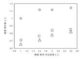
도 15는, 실시 형태 1에 있어서의 위치 어긋남 보정에 수반하는 최대 변조율과 최대 위치 어긋남양의 관계의 시뮬레이션 결과의 일례를 도시하는 도면이다. 도 15에 있어서 종축은 최대 변조율을 나타낸다. 횡축은 멀티 빔(20)의 최대 위치 어긋남양을 나타낸다. 최대 변조율은, 각 제어 그리트(27)로 도즈 분배된 각 도즈 분배율을 빔마다 합계한 합계 도즈 분배율 중 최댓값으로 정의한다. ◇로 나타내는 데이터는, 최근접 빔의 도즈 분배율이 나머지 빔 도즈 분배율보다 크게 되도록 고려하고 있지 않은 경우를 나타내고 있다. 도 15의 예에서는, 최근접 빔의 도즈 분배율을 크게 하는 고려를 실시하지 않으면, 어느 경우에서도 최대 변조율이 1 이상이 되는 것을 알 수 있다. 또한, 위치 어긋남양이 커지는 것에 수반하여, 최대 변조율도 커지는 것을 알 수 있다. 이에 비해, 실시 형태 1에서는, 최근접 빔의 도즈 분배율이 나머지 빔 도즈 분배율보다 커지도록 조합을 선택함으로써, 최대 변조율을 저감할 수 있다(□로 나타내는 데이터). 또한, 위치 어긋남양이 커지는 것에 수반하여, 최대 변조율도 커지는 경향은 마찬가지이다. 또한, 전류 밀도 보정값으로 도즈 분배율을 가중치 부여한데다 조합을 선택함으로써 최대 변조율을 더 저감할 수 있다(△로 나타내는 데이터). 도 15의 예에서의 전류 밀도 보정값은 식 (3)의 비를 사용한 경우를 나타내고 있다.FIG. 15 is a diagram showing an example of a simulation result of the relationship between the maximum modulation rate and the maximum amount of position misalignment accompanying position misalignment correction in
이어서, 반복 연산 처리 공정(S118)을 실시하는 경우에 대하여 설명한다.Next, a case where the iterative operation processing step (S118) is performed will be described.
반복 연산 처리 공정(S118)으로서, 반복 연산 처리부(64)는, 제어 그리드마다 선택되는 조합을 바꾸면서, 그때마다 빔 어레이 전체에 있어서의 빔의 설계상의 조사 위치마다 합계한 합계 도즈 분배율을 산출한다. 구체적으로는 이하와 같이 동작한다.As an iterative operation processing step (S118), the iterative
도 16은, 실시 형태 1에 있어서의 반복 연산 처리부의 내부 구성의 일례를 도시하는 블록도이다. 도 16에 있어서, 반복 연산 처리부(64) 내에는, 합성 맵 작성부(80), 판정부(82), 판정부(86) 및 조합 변경부(88)가 배치된다. 합성 맵 작성부(80), 판정부(82), 판정부(86) 및 조합 변경부(88)와 같은 각 「~부」는, 처리 회로를 갖는다. 이러한 처리 회로는, 예를 들어 전기 회로, 컴퓨터, 프로세서, 회로 기판, 양자 회로, 혹은, 반도체 장치를 포함한다. 각 「~부」는, 공통되는 처리 회로(동일한 처리 회로)를 사용해도 되고, 혹은 다른 처리 회로(별도의 처리 회로)를 사용해도 된다. 합성 맵 작성부(80), 판정부(82), 판정부(86) 및 조합 변경부(88)에 입출력되는 정보 및 연산 중의 정보는 메모리(112)에 그때마다 저장된다.Fig. 16 is a block diagram showing an example of the internal configuration of the iterative operation processing unit in
합성 맵 작성 공정(S120)으로서, 합성 맵 작성부(80)(합계 산출부)는 멀티 빔(20)의 빔 어레이 전체에 있어서의 제어 그리드(27)마다 선택되는 조합을 구성하는 2개 이상의 빔에 대한 도즈 분배율을, 빔의 설계상의 조사 위치마다 합계(합성)한 합계 도즈 분배율을 산출한다. 그리고, 각 빔의 설계상의 조사 위치의 합계 도즈 분배율을 요소로 하는 합성 맵을 작성한다. 합성 맵은, 멀티 빔(20)의 빔 어레이 배열과 마찬가지의 배열로 작성되면 적합하다. 1개의 빔에 복수의 제어 그리드(27)로부터 도즈 분배되는 경우가 있다. 그래서, 복수의 제어 그리드(27)로부터 도즈 분배된 각 도즈 분배율을 빔의 설계상의 조사 위치마다 합성한다. 여기에서는 단순하게 합계값을 산출하면 된다.In the synthesis map creation process (S120), the synthesis map creation unit 80 (total calculation unit) uses two or more beams constituting a combination selected for each
판정 공정(S122)으로서, 판정부(82)는, k회째의 제어 그리드(27)마다 선택된 조합에서의 각 빔의 설계상의 조사 위치의 합계 도즈 분배율의 최댓값(최대 변조량)이 k-1회째 이전의 제어 그리드(27)마다 선택된 조합에서의 각 빔의 설계상의 조사 위치의 합계 도즈 분배율의 최댓값(최대 변조량)보다도 작아진 것인지의 여부를 판정한다. 첫회는, 전회 이전의 합계 도즈 분배율의 최댓값과 비교할 수 없으므로, 작아지지 않는다고 판정하면 된다. 2회째 이후에서는, 전회 이전의 최대 변조량이 존재하므로 그때마다 대소 관계를 판정하면 된다. 최대 변조량이 작아진 경우에는, 조합 갱신 공정(S124)으로 진행한다. 최대 변조량이 작아지지 않은 경우에는, 조합 변경 공정(S125)으로 진행한다. 또한, 이 공정에서, 임시로, 합계 도즈 분배율을 갱신해도 된다. 그 경우의 갱신은 주목하고 있는 제어 그리드(27)에 영향을 미치는 부분만 실시한다.In the determination process (S122), the
조합 갱신 공정(S124)으로서, 조합 선택부(62)는, k회째(k는 2 이상의 정수)의 빔 어레이 전체에 있어서의 각 빔의 설계상의 조사 위치의 합계 도즈 분배율의 최댓값이 k-1회째 이전의 빔 어레이 전체에 있어서의 각 빔의 설계상의 조사 위치의 합계 도즈 분배율의 최댓값보다도 작은 경우에, k회째의 빔 어레이 전체에 있어서의 각 빔의 설계상의 조사 위치의 합계 도즈 분배율의 기초가 되는 제어 그리드(27)마다의 조합을 다시 선택한다. 바꿔 말하면, 현재 선택되고 있는 제어 그리드(27)마다의 조합을 갱신한다. 아울러, 합계 도즈 분배율을 갱신한다. 이 갱신은, 조합을 갱신한 제어 그리드(27)에 영향을 미치는 부분만 실시한다.In the combination update process (S124), the combination selection unit 62 selects the maximum value of the total dose distribution ratio of the designed irradiation positions of each beam in the entire beam array at the k-th time (k is an integer of 2 or more) at the k-1 time. If the total dose distribution ratio of the design irradiation positions of each beam in the entire previous beam array is smaller than the maximum value, the total dose distribution ratio of the design irradiation positions of each beam in the entire k-th beam array is the basis. The combination for each
조합 변경 공정(S125)으로서, 조합 변경부(88)는, 제어 그리드(27)마다 선택되는 조합을 변경한다. 제어 그리드(27)마다 최근접 빔은 특정되어 있다. 제2번째의 빔은 제한 영역(17) 내를 조사 위치(39)로 하는 빔으로 제한된다. 이러한 조건에서, 다른 조합으로 변경한다. 제어 그리드(27)마다, 최근접 빔의 도즈 분배율이 당해 조합을 구성하는 2개 이상의 빔의 나머지 1개 이상의 빔의 도즈 분배율보다도 커지는 조합이 2 이상 존재하는 경우에는, 이 중에서 조합을 변경해도 적합하다. 그리고, 합성 맵 작성 공정(S120)으로 복귀하여, 다음 판정 공정(S126)에서 규정 횟수에 도달할 때까지, 합성 맵 작성 공정(S120)으로부터 조합 변경 공정(S125)을 반복한다. 또한, 반복하는 경우의 합성 맵 작성 공정(S120)에서는, 빔 어레이 전체에 있어서의 각 빔의 설계상의 조사 위치의 합계 도즈 분배율을 다시 계산하는 경우에 한정되는 것은 아니고, 조합을 변경한 제어 그리드의 조합 대상이 되는 조사 위치에서의 합계 도즈 분배율만을 산출해도 된다.As a combination change process (S125), the
판정 공정(S126)으로서, 판정부(86)는, 조합 갱신이 이루어진 반복 연산 처리의 횟수 k가 미리 설정된 횟수 m에 도달했는지의 여부를 판정한다. 조합 갱신이 이루어진 반복 연산 처리의 횟수 k가 미리 설정된 횟수 m에 도달한 경우, 현재 선택되어 있는 제어 그리드(27)마다의 조합을 유지하여 반복 연산 처리를 종료한다. 조합 갱신이 이루어진 반복 연산 처리의 횟수 k가 미리 설정된 횟수 m에 달하지 않은 경우, 조합 변경 공정(S125)으로 진행한다. 조합 갱신이 이루어진 반복 연산 처리의 횟수 k가 m회에 달하고 있지 않아도, k-1회째와의 최댓값의 차분이, 미리 설정된 값보다도 작은 경우에 반복 연산 처리를 종료해도 적합하다. 또한, 반복 연산 처리를 행한 결과, 조합 갱신이 이루어지는 일이 없었던 경우에도, 제어 그리드마다 당해 제어 그리드에서의 반복 연산 처리의 횟수가 미리 설정된 횟수 q에 달하면 당해 제어 그리드에서의 반복 연산 처리를 종료해도 상관없다.As a determination process (S126), the
그리고, 합성 맵 작성 공정(S120)으로 복귀하여, 반복 연산 처리의 횟수 k가 미리 설정된 횟수 m에 도달할 때까지, 합성 맵 작성 공정(S120)으로부터 조합 변경 공정(S125)까지의 각 공정을 반복한다.Then, it returns to the synthetic map creation process (S120), and repeats each process from the synthetic map creation process (S120) to the combination change process (S125) until the number k of repetitive operation processing reaches the preset number m. do.
합성 맵 작성부(80)는, 제어 그리드(27)마다 선택되는 조합을 바꾸면서, 그때마다 빔 어레이 전체에 있어서의 빔의 설계상의 조사 위치마다 합계한 합계 도즈 분배율을 산출한다. 조합을 변경 후의 각 조합을 구성하는 2개 이상의 빔에 대한 각 도즈 분배율은 도즈 분배율 산출 공정(S110)에서 이미 산출된 결과를 유용하면 된다.The composite
제어 그리드(27)마다의 조합을 바꿈으로써, 빔의 설계상의 조사 위치마다의 합계 도즈 분배율이 변화한다. 이 결과, 합성 후의 최대 변조율이 변화한다. 따라서, 반복 연산 처리(인터레이션)를 행함으로써, 최대 변조율을 더 저감할 수 있다.By changing the combination for each
그리고, 제어 그리드(27)마다 선택된 조합을 구성하는 2개 이상의 빔에 대한 빔의 변조율은, 위치 어긋남 보정 데이터로서, 기억 장치(144)에 저장된다. 위치 어긋남 보정 데이터는, 조사 영역(34)에 대응하는 시료면 상의 1개의 직사각형 단위 영역(35)에 대해서 작성되면 된다.And, the beam modulation rates for two or more beams constituting the combination selected for each
도즈양 연산 공정(S130)으로서, 도즈 맵 작성부(68)(도즈양 연산부)는 묘화 패턴마다, 당해 묘화 패턴에 따른 시료(101) 상의 각 화소(36)의 개별의 도즈양을 연산한다. 구체적으로는, 이하와 같이 동작한다. 먼저, 래스터라이즈부(66)는, 기억 장치(140)로부터 묘화 데이터를 읽어내고, 화소(36)마다, 당해 화소(36) 내의 패턴 면적 밀도 ρ'을 연산한다. 이러한 처리는, 예를 들어 스트라이프 영역(32)마다 실행한다.As a dose calculation process (S130), the dose map creation unit 68 (dose calculation unit) calculates, for each drawing pattern, the individual dose amount of each
이어서, 도즈 맵 작성부(68)는, 먼저, 묘화 영역(여기서는, 예를 들어 스트라이프 영역(32))을 소정의 사이즈로 메쉬상으로 복수의 근접 메쉬 영역(근접 효과 보정 계산용 메쉬 영역)으로 가상 분할한다. 근접 메쉬 영역의 사이즈는, 근접 효과의 영향 범위의 1/10 정도, 예를 들어 1㎛ 정도로 설정하면 적합하다. 도즈 맵 작성부(68)는, 기억 장치(140)로부터 묘화 데이터를 읽어내고, 근접 메쉬 영역마다, 당해 근접 메쉬 영역 내에 배치되는 패턴의 패턴 면적 밀도 ρ를 연산한다.Next, the dose map creation unit 68 first converts the drawing area (here, for example, the stripe area 32) into a plurality of proximity mesh areas (mesh areas for proximity effect correction calculation) on a mesh of a predetermined size. Virtual partition. It is appropriate to set the size of the proximity mesh area to about 1/10 of the influence range of the proximity effect, for example, about 1㎛. The dose map creation unit 68 reads the drawing data from the storage device 140 and calculates, for each adjacent mesh area, the pattern area density ρ of the pattern disposed within the adjacent mesh area.
이어서, 도즈 맵 작성부(68)는, 근접 메쉬 영역마다, 근접 효과를 보정하기 위한 근접 효과 보정 조사 계수 Dp(x)(보정 조사량)를 연산한다. 미지의 근접 효과 보정 조사 계수 Dp(x)는, 후방 산란 계수 η, 역치 모델의 조사량 역치 Dth, 패턴 면적 밀도 ρ 및 분포 함수 g(x)를 사용한, 종래 방법과 마찬가지의 근접 효과 보정용의 역치 모델에 의해 정의할 수 있다.Next, the dose map creation unit 68 calculates a proximity effect correction irradiation coefficient Dp(x) (corrected irradiation amount) for correcting the proximity effect for each proximity mesh area. The unknown proximity effect correction irradiation coefficient Dp(x) is a threshold model for proximity effect correction similar to the conventional method using the backscattering coefficient η, the irradiance threshold Dth of the threshold model, the pattern area density ρ, and the distribution function g(x). It can be defined by:
이어서, 도즈 맵 작성부(68)는, 화소(36)마다, 당해 화소(36)에 조사하기 위한 입사 조사량 D(x)(도즈양)를 연산한다. 입사 조사량 D(x)는, 예를 들어 미리 설정된 기준 조사량 Dbase에 근접 효과 보정 조사 계수 Dp와 패턴 면적 밀도 ρ'을 곱한 값으로서 연산하면 된다. 기준 조사량 Dbase는, 예를 들어 Dth/(1/2+η)로 정의할 수 있다. 이상에 의해, 묘화 데이터에 정의되는 복수의 도형 패턴의 레이아웃에 기초한, 근접 효과가 보정된 본래의 원하는 입사 조사량 D(x)를 얻을 수 있다.Next, the dose map creation unit 68 calculates, for each
그리고, 도즈 맵 작성부(68)는, 스트라이프 단위로 화소(36)마다의 입사 조사량 D(x)를 정의한 도즈 맵을 작성한다. 이러한 화소(36)마다의 입사 조사량 D(x)는 설계상, 당해 화소(36)의 제어 그리드(27)에 조사될 예정의 입사 조사량 D(x)가 된다. 바꿔 말하면, 도즈 맵 제작부(68)는, 스트라이프 단위로 제어 그리드(27)마다의 입사 조사량 D(x)를 정의한 도즈 맵을 작성한다. 이 작성된 도즈 맵은, 예를 들어 기억 장치(144)에 저장된다.Then, the dose map creation unit 68 creates a dose map defining the incident irradiance D(x) for each
도즈 보정 공정(S134)으로서, 도즈 보정부(70)는, 묘화 패턴마다, 기억 장치(144)로부터 위치 어긋남 보정 데이터를 읽어내고, 당해 묘화 패턴에 따른 각 화소의 개별의 도즈양에 위치 어긋남 보정 데이터를 적용하여, 도즈양을 보정한다. 구체적으로는, 도즈 보정부(70)는, 제어 그리드(27)마다, 대상의 제어 그리드(27)에 조사될 예정의 입사 조사량 D(x)를 도즈 분배율에 따라서 조합을 구성하는 2개 이상의 빔이 조사하는 설계상의 조사 위치가 되는 화소에 분배된다. 그리고, 빔의 설계상의 조사 위치가 되는 화소마다 분배된 도즈양을 가산한다. 바꿔 말하면, 도즈 보정부(70)는, 화소마다 분배된 도즈양을 당해 화소의 도즈양에 가산함으로써 보정하고, 보정된 보정 도즈양을 출력한다. 가산되는 당해 화소의 도즈양은, 다른 화소에의 분배가 있는 경우에는, 다른 화소에 분배되어 남은 도즈양에 상당한다.In the dose correction process (S134), the dose correction unit 70 reads positional misalignment correction data from the storage device 144 for each drawing pattern, and performs positional misalignment correction for the individual dose amount of each pixel according to the drawing pattern. Apply the data to correct the dose. Specifically, the dose correction unit 70 uses, for each
조사 시간 연산 공정(S140)으로서, 조사 시간 연산부(72)는, 빔의 위치 어긋남이 보정된 각 화소의 도즈양에 대응하는 조사 시간 t를 연산한다. 조사 시간 t는, 도즈양 D를 전류 밀도 J로 나눔으로써 연산할 수 있다. 각 화소(36)(제어 그리드(27))의 조사 시간 t는, 멀티 빔(20)의 1샷으로 조사 가능한 최대 조사 시간 Ttr 내의 값으로서 연산된다. 각 화소(36)(제어 그리드(27))의 조사 시간 t는, 최대 조사 시간 Ttr을 예를 들어 1023계조(10비트)로 하는 0 내지 1023계조의 계조값 데이터로 변환한다. 계조화된 조사 시간 데이터는 기억 장치(142)에 저장된다.As an irradiation time calculation process (S140), the irradiation time calculation unit 72 calculates an irradiation time t corresponding to the dose amount of each pixel for which the beam positional deviation has been corrected. Irradiation time t can be calculated by dividing the dose amount D by the current density J. The irradiation time t of each pixel 36 (control grid 27) is calculated as a value within the maximum irradiation time Ttr that can be irradiated with one shot of the multi-beam 20. The irradiation time t of each pixel 36 (control grid 27) is converted into gradation value data of 0 to 1023 gradations with the maximum irradiation time Ttr being, for example, 1023 gradations (10 bits). The grayscale irradiation time data is stored in the memory device 142.
묘화 공정(S142)으로서, 먼저, 묘화 제어부(74)는, 조사 시간 데이터를 묘화 시퀀스를 따라 샷순으로 재배열한다. 그리고, 샷순으로 조사 시간 데이터를 편향 제어 회로(130)에 전송한다. 편향 제어 회로(130)는, 블랭킹 애퍼처 어레이 기구(204)에 샷순으로 블랭킹 제어 신호를 출력함과 함께, DAC 앰프 유닛(132, 134)에 샷순으로 편향 제어 신호를 출력한다. 그리고, 묘화 기구(150)는, 각 제어 그리드(27)에 조사될 예정의 도즈양이 각각 선택된 조합을 구성하는 2개 이상의 빔으로 분배된 멀티 빔(20)을 사용하여, 시료(101)에 패턴을 묘화한다. 바꿔 말하면, 도즈 보정 공정(S134)에 의한 도즈양의 가산에 의해 보정된 보정 도즈양의 멀티 빔(20)을 사용하여, 시료(101)에 패턴을 묘화한다.As a drawing process (S142), first, the drawing control unit 74 rearranges the irradiation time data in shot order along the drawing sequence. Then, irradiation time data is transmitted to the deflection control circuit 130 in shot order. The deflection control circuit 130 outputs blanking control signals to the blanking
이상과 같이, 실시 형태 1에 의하면, 멀티 빔 묘화에 있어서, 각 빔의 위치 어긋남 보정을 도즈 변조에 의해 행하는 경우에 있어서의 도즈 변조율의 증대를 억제할 수 있다. 따라서, 최대 조사 시간의 증대를 억제하고, 나아가서는 묘화 시 간의 증가를 억제할 수 있다.As described above, according to
이상, 구체예를 참조하면서 실시 형태에 대하여 설명하였다. 그러나, 본 발명은 이들의 구체예에 한정되는 것은 아니다. 상술한 예에서는, 1샷분의 최대 조사 시간 Ttr 내에서, 멀티 빔(20)의 각 빔이 조사 시간을 빔마다 개별로 제어하는 경우에 대하여 설명하였다. 그러나, 이것에 한정되는 것은 아니다. 예를 들어, 1샷분의 최대 조사 시간 Ttr을 조사 시간이 다른 복수의 서브 샷으로 분할한다. 그리고, 각 빔에 대하여 각각 복수의 서브 샷 중에서 1샷분의 조사 시간이 되도록 서브 샷의 조합을 선택한다. 그리고, 동일한 화소에 대하여 연속하여 동일한 빔에서 선택된 서브 샷의 조합분이 조사됨으로써, 빔마다 1샷분의 조사 시간을 제어하도록 해도 적합하다.Above, embodiments have been described with reference to specific examples. However, the present invention is not limited to these specific examples. In the above-described example, the case where the irradiation time of each beam of the multi-beam 20 is individually controlled for each beam within the maximum irradiation time Ttr for one shot has been described. However, it is not limited to this. For example, the maximum irradiation time Ttr for one shot is divided into a plurality of sub-shots with different irradiation times. Then, for each beam, a combination of sub-shots is selected from among the plurality of sub-shots so that the irradiation time is equivalent to one shot. Additionally, since a combination of sub-shots selected from the same beam is successively irradiated to the same pixel, it is also suitable to control the irradiation time for one shot for each beam.
또한, 장치 구성이나 제어 방법 등, 본 발명의 설명에 직접 필요하지 않은 부분 등에 대해서는 기재를 생략했지만, 필요로 되는 장치 구성이나 제어 방법을 적절히 선택하여 사용할 수 있다. 예를 들어, 묘화 장치(100)를 제어하는 제어부 구성에 대해서는, 기재를 생략했지만, 필요로 되는 제어부 구성을 적절히 선택하여 사용하는 것은 물론이다.In addition, the description of parts that are not directly necessary for the description of the present invention, such as the device configuration and control method, has been omitted, but the required device configuration or control method can be appropriately selected and used. For example, the description of the control unit configuration for controlling the drawing device 100 is omitted, but it goes without saying that the required control unit configuration can be appropriately selected and used.
그 밖에, 본 발명의 요소를 구비하고, 당업자가 적절히 설계 변경할 수 있는 모든 멀티 하전 입자 빔 묘화 장치 및 멀티 하전 입자 빔 묘화 방법은, 본 발명의 범위에 포함된다.In addition, all multi-charged particle beam drawing devices and multi-charged particle beam drawing methods that have the elements of the present invention and can be appropriately designed and modified by those skilled in the art are included in the scope of the present invention.
본 발명의 일 양태는, 멀티 하전 입자 빔 묘화 장치 및 멀티 하전 입자 빔 묘화 방법에 관한 것이고, 예를 들어 멀티 빔 묘화에 의한 패턴의 치수 어긋남을 저감하는 방법에 이용할 수 있다.One aspect of the present invention relates to a multi-charged particle beam drawing device and a multi-charged particle beam drawing method, and can be used, for example, in a method of reducing dimensional deviation of a pattern due to multi-beam drawing.
20: 멀티 빔
22: 구멍
24: 제어 전극
25: 통과 구멍
26: 대향 전극
27: 제어 그리드
28: 화소
29: 서브 조사 영역
30: 묘화 영역
32: 스트라이프 영역
31: 기판
33: 지지대
34: 조사 영역
35: 직사각형 단위 영역
36: 화소
39: 조사 위치
41: 제어 회로
50: 빔 위치 어긋남 맵 작성부
52: 특정부
54: 영역 제한부
56: 설정부
58: 도즈 분배율 산출부
60: 전류 밀도 보정부
62: 조합 선택부
64: 반복 연산 처리부
66: 래스터라이즈부
68: 도즈 맵 작성부
70: 도즈 보정부
72: 조사 시간 연산부
74: 묘화 제어부
80: 합성 맵 작성부
82, 86: 판정부
88: 조합 변경부
100: 묘화 장치
101: 시료
102: 전자 경통
103: 묘화실
105: XY 스테이지
110: 제어 계산기
112: 메모리
130: 편향 제어 회로
132, 134: DAC 앰프 유닛
139: 스테이지 위치 검출기
140, 142, 144: 기억 장치
150: 묘화 기구
160: 제어계 회로
200: 전자 빔
201: 전자총
202: 조명 렌즈
203: 성형 애퍼처 어레이 기판
204: 블랭킹 애퍼처 어레이 기구
205: 축소 렌즈
206: 제한 애퍼처 기판
207: 대물 렌즈
208, 209: 편향기
210: 미러
330: 멤브레인 영역
332: 외주 영역20: multi beam
22: hole
24: control electrode
25: Through hole
26: counter electrode
27: Control grid
28: pixel
29: Sub-survey area
30: Drawing area
32: Stripe area
31: substrate
33: support
34: Investigation area
35: Rectangular unit area
36: pixel
39: Survey location
41: control circuit
50: Beam position misalignment map creation unit
52: Specific part
54: Area limitation unit
56: Setting section
58: Dose distribution ratio calculation unit
60: Current density correction unit
62: Combination selection unit
64: repetitive operation processing unit
66: Rasterization section
68: Dose map creation unit
70: Dose correction unit
72: Survey time calculation unit
74: Drawing control unit
80: Synthetic map creation unit
82, 86: Jury
88: Combination change section
100: Drawing device
101: sample
102: Electronic barrel
103: Drawing room
105: XY stage
110: Control calculator
112: memory
130: Deflection control circuit
132, 134: DAC amplifier unit
139: Stage position detector
140, 142, 144: memory device
150: Drawing mechanism
160: Control system circuit
200: electron beam
201: Electron gun
202: lighting lens
203: Molded aperture array substrate
204: Blanking aperture array mechanism
205: reduction lens
206: limited aperture substrate
207: Objective lens
208, 209: Deflector
210: mirror
330: Membrane area
332: Outsourcing area
Claims (10)
Translated fromKorean상기 멀티 하전 입자 빔의 설계상의 조사 위치가 되는 복수의 설계 그리드의 설계 그리드마다, 상기 멀티 하전 입자 빔 중, 대상 빔의 설계 그리드로부터 실제의 조사 위치가 가장 가까운 제1 빔을 특정하는 특정 회로와,
설계 그리드마다, 상기 멀티 하전 입자 빔으로부터 상기 제1 빔을 포함하는 2개 이상의 빔으로 구성되는 복수의 조합을 설정하는 조합 설정 회로와,
설계 그리드마다, 또한, 상기 복수의 조합의 조합마다, 당해 조합을 구성하는 2개 이상의 빔에, 분배 후의 각 분배 도즈양의 총합이 당해 설계 그리드에 조사될 예정의 도즈양과 동등해지도록 당해 설계 그리드에 조사될 예정의 상기 도즈양을 분배하기 위한, 당해 조합을 구성하는 상기 2개 이상의 빔의 각 빔에 대한 도즈 분배율을 산출하는 분배율 산출 회로와,
설계 그리드마다, 상기 제1 빔의 도즈 분배율이 당해 조합을 구성하는 2개 이상의 빔의 나머지 1개 이상의 빔의 도즈 분배율보다도 커지는 조합을 선택하는 조합 선택 회로와,
상기 멀티 하전 입자 빔의 빔 어레이 전체에 있어서의 설계 그리드마다 선택되는 조합을 구성하는 상기 2개 이상의 빔에 대한 도즈 분배율에 따라, 빔의 설계상의 조사 위치마다 분배된 상기 도즈양을 당해 조사 위치의 도즈양에 가산함으로써 보정하고, 이 보정된 보정 도즈양을 출력하는 도즈 보정 회로와,
상기 보정 도즈양의 멀티 하전 입자 빔을 사용하여, 시료에 패턴을 묘화하는 묘화 기구
를 구비한, 멀티 하전 입자 빔 묘화 장치.a beam forming mechanism that forms a multi-charged particle beam;
A specific circuit that specifies, for each design grid of the plurality of design grids that are the design irradiation positions of the multi-charged particle beam, a first beam whose actual irradiation position is closest to the design grid of the target beam among the multi-charged particle beams; ,
a combination setting circuit that sets, for each design grid, a plurality of combinations consisting of two or more beams including the first beam from the multi-charged particle beam;
For each design grid, and for each combination of the plurality of combinations, the design grid such that the total of the distributed doses after distribution to the two or more beams constituting the combination is equal to the dose amount scheduled to be irradiated to the design grid. a distribution ratio calculation circuit for calculating a dose distribution ratio for each beam of the two or more beams constituting the combination, for distributing the dose amount scheduled to be irradiated;
For each design grid, a combination selection circuit that selects a combination in which the dose distribution ratio of the first beam is greater than the dose distribution ratio of the remaining one or more beams of the two or more beams constituting the combination;
According to the dose distribution ratio for the two or more beams constituting the combination selected for each design grid in the entire beam array of the multi-charged particle beam, the dose amount distributed to each design irradiation position of the beam is divided into the corresponding irradiation position. a dose correction circuit that corrects by adding to the dose amount and outputs this corrected correction dose amount;
A drawing mechanism for drawing a pattern on a sample using a multi-charged particle beam of the above-described corrected dose.
Equipped with a multi-charged particle beam drawing device.
상기 합계 산출 회로는, 설계 그리드마다 선택되는 조합을 바꾸면서, 그때마다 빔 어레이 전체에 있어서의 상기 빔의 설계상의 조사 위치마다 합계한 합계 도즈 분배율을 산출하고,
상기 조합 선택 회로는, k회째(k는 2 이상의 정수)의 빔 어레이 전체에 있어서의 각 빔의 설계상의 조사 위치의 합계 도즈 분배율의 최댓값이 k-1회째 이전의 빔 어레이 전체에 있어서의 각 빔의 설계상의 조사 위치의 합계 도즈 분배율의 최댓값보다도 작은 경우에, k회째의 빔 어레이 전체에 있어서의 각 빔의 설계상의 조사 위치의 합계 도즈 분배율의 기초가 되는 설계 그리드마다의 조합을 다시 선택하는, 멀티 하전 입자 빔 묘화 장치.The total dose distribution ratio according to claim 1, wherein the dose distribution ratio for the two or more beams constituting a combination selected for each design grid in the entire beam array of the multi-charged particle beam is summed for each design irradiation position of the beam. It is further provided with a total calculation circuit that calculates,
The total calculation circuit changes the combination selected for each design grid and calculates the total dose distribution ratio for each design irradiation position of the beam in the entire beam array each time,
The combination selection circuit is such that the maximum value of the total dose distribution ratio of the designed irradiation positions of each beam in the entire beam array of the k-th time (k is an integer of 2 or more) is determined by determining the maximum value of the total dose distribution ratio of each beam in the entire beam array before the k-1 time. If the total dose distribution ratio of the designed irradiation positions is smaller than the maximum value, the combination for each design grid that serves as the basis for the total dose distribution ratio of the designed irradiation positions of each beam in the entire k-th beam array is selected again. Multi-charged particle beam imaging device.
상기 멀티 하전 입자 빔의 설계상의 조사 위치가 되는 복수의 설계 그리드의 설계 그리드마다, 상기 멀티 하전 입자 빔 중, 대상 빔의 설계 그리드로부터 실제의 조사 위치가 가장 가까운 제1 빔을 특정하고,
설계 그리드마다, 상기 멀티 하전 입자 빔으로부터 상기 제1 빔을 포함하는 2개 이상의 빔으로 구성되는 복수의 조합을 설정하고,
설계 그리드마다, 또한, 상기 복수의 조합의 조합마다, 당해 조합을 구성하는 2개 이상의 빔에, 분배 후의 각 분배 도즈양의 총합이 당해 설계 그리드에 조사될 예정의 도즈양과 동등해지도록 당해 설계 그리드에 조사될 예정의 상기 도즈양을 분배하기 위한, 당해 조합을 구성하는 상기 2개 이상의 빔의 각 빔에 대한 도즈 분배율을 산출하고,
설계 그리드마다, 상기 제1 빔의 도즈 분배율이 당해 조합을 구성하는 2개 이상의 빔의 나머지 1개 이상의 빔의 도즈 분배율보다도 커지는 조합을 선택하고,
상기 멀티 하전 입자 빔의 빔 어레이 전체에 있어서의 설계 그리드마다 선택되는 조합을 구성하는 상기 2개 이상의 빔에 대한 도즈 분배율에 따라, 빔의 설계상의 조사 위치마다 분배된 상기 도즈양을 당해 조사 위치의 도즈양에 가산함으로써 보정하고, 이 보정된 보정 도즈양을 출력하고,
상기 보정 도즈양의 멀티 하전 입자 빔을 사용하여, 시료에 패턴을 묘화하는,
멀티 하전 입자 빔 묘화 방법.forming a beam of multi-charged particles,
A first beam whose actual irradiation position is closest to the design grid of the target beam is specified for each design grid of the plurality of design grids that are the designed irradiation positions of the multi-charged particle beam,
For each design grid, a plurality of combinations consisting of two or more beams including the first beam are set from the multi-charged particle beam,
For each design grid, and for each combination of the plurality of combinations, the design grid such that the total of the distributed doses after distribution to the two or more beams constituting the combination is equal to the dose amount scheduled to be irradiated to the design grid. Calculating a dose distribution ratio for each beam of the two or more beams constituting the combination for distributing the dose amount scheduled to be irradiated,
For each design grid, select a combination in which the dose distribution ratio of the first beam is greater than the dose distribution ratio of the remaining one or more beams of the two or more beams constituting the combination,
According to the dose distribution ratio for the two or more beams constituting the combination selected for each design grid in the entire beam array of the multi-charged particle beam, the dose amount distributed to each design irradiation position of the beam is divided into the corresponding irradiation position. Correction is made by adding to the dose amount, and this corrected correction dose amount is output.
Drawing a pattern on a sample using a multi-charged particle beam of the corrected dose,
Multi-charged particle beam imaging method.
The method of claim 8, wherein the limiting area is perpendicular to a straight line connecting the design grid of the target of the first beam and the irradiation position of the first beam, and passes through the design grid of the target of the first beam. A multi-charged particle beam drawing method, wherein the area is opposite to the irradiation position of the first beam with respect to a straight line.
Applications Claiming Priority (3)
| Application Number | Priority Date | Filing Date | Title |
|---|---|---|---|
| JP2021165705AJP7705332B2 (en) | 2021-10-07 | 2021-10-07 | Multi-charged particle beam writing apparatus and charged particle beam writing method |
| JPJP-P-2021-165705 | 2021-10-07 | ||
| PCT/JP2022/027527WO2023058290A1 (en) | 2021-10-07 | 2022-07-13 | Multi-charged particle beam drawing apparatus and charged particle beam drawing method |
Publications (1)
| Publication Number | Publication Date |
|---|---|
| KR20240047457Atrue KR20240047457A (en) | 2024-04-12 |
Family
ID=85804127
Family Applications (1)
| Application Number | Title | Priority Date | Filing Date |
|---|---|---|---|
| KR1020247009653APendingKR20240047457A (en) | 2021-10-07 | 2022-07-13 | Multi-charged particle beam writing device and charged particle beam writing method |
Country Status (6)
| Country | Link |
|---|---|
| US (1) | US20240242932A1 (en) |
| JP (1) | JP7705332B2 (en) |
| KR (1) | KR20240047457A (en) |
| CN (1) | CN118056264A (en) |
| TW (1) | TWI844911B (en) |
| WO (1) | WO2023058290A1 (en) |
Citations (1)
| Publication number | Priority date | Publication date | Assignee | Title |
|---|---|---|---|---|
| JP2019029575A (en) | 2017-08-02 | 2019-02-21 | 株式会社ニューフレアテクノロジー | Multiple charged particle beam lithography apparatus and multiple charged particle beam lithography method |
Family Cites Families (6)
| Publication number | Priority date | Publication date | Assignee | Title |
|---|---|---|---|---|
| EP3358599B1 (en)* | 2014-05-30 | 2021-01-27 | IMS Nanofabrication GmbH | Compensation of dose inhomogeneity using row calibration |
| JP6438280B2 (en)* | 2014-11-28 | 2018-12-12 | 株式会社ニューフレアテクノロジー | Multi-charged particle beam writing apparatus and multi-charged particle beam writing method |
| JP7002243B2 (en)* | 2017-08-04 | 2022-01-20 | 株式会社ニューフレアテクノロジー | Multi-charged particle beam drawing device and multi-charged particle beam drawing method |
| JP7024616B2 (en)* | 2018-06-08 | 2022-02-24 | 株式会社ニューフレアテクノロジー | Data processing method, data processing device, and multi-charged particle beam drawing device |
| JP7239282B2 (en)* | 2018-08-03 | 2023-03-14 | 株式会社ニューフレアテクノロジー | Multi-charged particle beam writing apparatus and multi-charged particle beam writing method |
| JP7196792B2 (en)* | 2019-07-11 | 2022-12-27 | 株式会社ニューフレアテクノロジー | Multi-beam writing method and multi-beam writing apparatus |
- 2021
- 2021-10-07JPJP2021165705Apatent/JP7705332B2/enactiveActive
- 2022
- 2022-07-13WOPCT/JP2022/027527patent/WO2023058290A1/ennot_activeCeased
- 2022-07-13CNCN202280065700.1Apatent/CN118056264A/enactivePending
- 2022-07-13KRKR1020247009653Apatent/KR20240047457A/enactivePending
- 2022-08-10TWTW111129977Apatent/TWI844911B/enactive
- 2024
- 2024-03-29USUS18/621,345patent/US20240242932A1/enactivePending
Patent Citations (1)
| Publication number | Priority date | Publication date | Assignee | Title |
|---|---|---|---|---|
| JP2019029575A (en) | 2017-08-02 | 2019-02-21 | 株式会社ニューフレアテクノロジー | Multiple charged particle beam lithography apparatus and multiple charged particle beam lithography method |
Also Published As
| Publication number | Publication date |
|---|---|
| TW202331777A (en) | 2023-08-01 |
| CN118056264A (en) | 2024-05-17 |
| US20240242932A1 (en) | 2024-07-18 |
| TWI844911B (en) | 2024-06-11 |
| JP2023056384A (en) | 2023-04-19 |
| JP7705332B2 (en) | 2025-07-09 |
| WO2023058290A1 (en) | 2023-04-13 |
Similar Documents
| Publication | Publication Date | Title |
|---|---|---|
| KR101843057B1 (en) | Multi charged particle beam writing apparatus and multi charged particle beam writing method | |
| KR102093808B1 (en) | Multi charged-particle beam writing apparatus and multi charged-particle beam writing method | |
| US9601315B2 (en) | Multiple charged particle beam lithography apparatus and multiple charged particle beam pattern writing method | |
| KR102303435B1 (en) | Multi-charged particle beam writing apparatus and multi-charged particle beam writing method | |
| KR102093809B1 (en) | Multi charged-particle beam writing apparatus and multi charged-particle beam writing method | |
| JP7002837B2 (en) | Multi-charged particle beam drawing device and multi-charged particle beam drawing method | |
| KR102410976B1 (en) | Multi charged particle beam drawing device and multi charged particle beam drawing method | |
| US10269532B2 (en) | Multi charged particle beam exposure method, and multi charged particle beam exposure apparatus | |
| KR20220045887A (en) | Multi-charged particle beam writing apparatus and multi-charged particle beam writing method | |
| CN115398598B (en) | Multi-charged particle beam drawing device and multi-charged particle beam drawing method | |
| KR102810945B1 (en) | Multi-charged particle beam writing device and multi-charged particle beam writing method | |
| KR102550381B1 (en) | Multi-beam writing method and multi-beam writing apparatus | |
| KR20240047457A (en) | Multi-charged particle beam writing device and charged particle beam writing method | |
| WO2023234178A1 (en) | Multi-charged particle beam drawing device and multi-charged particle beam drawing method | |
| KR20240137088A (en) | Multi-charged particle beam writing device and multi-charged particle beam writing method |
Legal Events
| Date | Code | Title | Description |
|---|---|---|---|
| A201 | Request for examination | ||
| E13-X000 | Pre-grant limitation requested | St.27 status event code:A-2-3-E10-E13-lim-X000 | |
| P11-X000 | Amendment of application requested | St.27 status event code:A-2-2-P10-P11-nap-X000 | |
| P13-X000 | Application amended | St.27 status event code:A-2-2-P10-P13-nap-X000 | |
| PA0105 | International application | St.27 status event code:A-0-1-A10-A15-nap-PA0105 | |
| PA0201 | Request for examination | St.27 status event code:A-1-2-D10-D11-exm-PA0201 | |
| PG1501 | Laying open of application | St.27 status event code:A-1-1-Q10-Q12-nap-PG1501 | |
| PE0902 | Notice of grounds for rejection | St.27 status event code:A-1-2-D10-D21-exm-PE0902 | |
| E13-X000 | Pre-grant limitation requested | St.27 status event code:A-2-3-E10-E13-lim-X000 | |
| P11-X000 | Amendment of application requested | St.27 status event code:A-2-2-P10-P11-nap-X000 |