KR20240037245A - Droplet delivery device by push ejection - Google Patents
Droplet delivery device by push ejectionDownload PDFInfo
- Publication number
- KR20240037245A KR20240037245AKR1020247002301AKR20247002301AKR20240037245AKR 20240037245 AKR20240037245 AKR 20240037245AKR 1020247002301 AKR1020247002301 AKR 1020247002301AKR 20247002301 AKR20247002301 AKR 20247002301AKR 20240037245 AKR20240037245 AKR 20240037245A
- Authority
- KR
- South Korea
- Prior art keywords
- delivery device
- mesh
- droplet delivery
- membrane
- droplet
- Prior art date
- Legal status (The legal status is an assumption and is not a legal conclusion. Google has not performed a legal analysis and makes no representation as to the accuracy of the status listed.)
- Pending
Links
- 239000012528membraneSubstances0.000claimsabstractdescription202
- 239000012530fluidSubstances0.000claimsabstractdescription92
- 239000000463materialSubstances0.000claimsdescription60
- 229920000642polymerPolymers0.000claimsdescription58
- 230000007246mechanismEffects0.000claimsdescription24
- 239000011248coating agentSubstances0.000claimsdescription22
- 238000000576coating methodMethods0.000claimsdescription22
- 229910052751metalInorganic materials0.000claimsdescription21
- 239000002184metalSubstances0.000claimsdescription21
- 238000000034methodMethods0.000claimsdescription18
- 238000012546transferMethods0.000claimsdescription16
- KDLHZDBZIXYQEI-UHFFFAOYSA-NPalladiumChemical compound[Pd]KDLHZDBZIXYQEI-UHFFFAOYSA-N0.000claimsdescription15
- 230000002209hydrophobic effectEffects0.000claimsdescription15
- 238000004891communicationMethods0.000claimsdescription12
- 239000010936titaniumSubstances0.000claimsdescription12
- RTAQQCXQSZGOHL-UHFFFAOYSA-NTitaniumChemical compound[Ti]RTAQQCXQSZGOHL-UHFFFAOYSA-N0.000claimsdescription10
- 229910052782aluminiumInorganic materials0.000claimsdescription10
- XAGFODPZIPBFFR-UHFFFAOYSA-NaluminiumChemical compound[Al]XAGFODPZIPBFFR-UHFFFAOYSA-N0.000claimsdescription10
- 229920001643poly(ether ketone)Polymers0.000claimsdescription10
- 239000000126substanceSubstances0.000claimsdescription10
- 229910052719titaniumInorganic materials0.000claimsdescription10
- PXHVJJICTQNCMI-UHFFFAOYSA-NNickelChemical compound[Ni]PXHVJJICTQNCMI-UHFFFAOYSA-N0.000claimsdescription9
- 230000001413cellular effectEffects0.000claimsdescription9
- 229910052763palladiumInorganic materials0.000claimsdescription9
- OKTJSMMVPCPJKN-UHFFFAOYSA-NCarbonChemical compound[C]OKTJSMMVPCPJKN-UHFFFAOYSA-N0.000claimsdescription8
- 239000004677NylonSubstances0.000claimsdescription8
- 239000002131composite materialSubstances0.000claimsdescription8
- 229910002804graphiteInorganic materials0.000claimsdescription8
- 239000010439graphiteSubstances0.000claimsdescription8
- 229920001778nylonPolymers0.000claimsdescription8
- 238000007789sealingMethods0.000claimsdescription8
- -1polytetrafluoroethylenePolymers0.000claimsdescription7
- SNICXCGAKADSCV-JTQLQIEISA-N(-)-NicotineChemical compoundCN1CCC[C@H]1C1=CC=CN=C1SNICXCGAKADSCV-JTQLQIEISA-N0.000claimsdescription6
- 239000004642PolyimideSubstances0.000claimsdescription6
- 230000008859changeEffects0.000claimsdescription6
- 239000003814drugSubstances0.000claimsdescription6
- 229960002715nicotineDrugs0.000claimsdescription6
- SNICXCGAKADSCV-UHFFFAOYSA-NnicotineNatural productsCN1CCCC1C1=CC=CN=C1SNICXCGAKADSCV-UHFFFAOYSA-N0.000claimsdescription6
- 238000004806packaging method and processMethods0.000claimsdescription6
- 239000011112polyethylene naphthalateSubstances0.000claimsdescription6
- 229920001721polyimidePolymers0.000claimsdescription6
- 230000001225therapeutic effectEffects0.000claimsdescription6
- 229920003207poly(ethylene-2,6-naphthalate)Polymers0.000claimsdescription5
- 229920000049Carbon (fiber)Polymers0.000claimsdescription4
- 239000004697PolyetherimideSubstances0.000claimsdescription4
- 239000004699Ultra-high molecular weight polyethyleneSubstances0.000claimsdescription4
- 239000004917carbon fiberSubstances0.000claimsdescription4
- 239000000919ceramicSubstances0.000claimsdescription4
- 239000000835fiberSubstances0.000claimsdescription4
- VNWKTOKETHGBQD-UHFFFAOYSA-NmethaneChemical compoundCVNWKTOKETHGBQD-UHFFFAOYSA-N0.000claimsdescription4
- 229920001601polyetherimidePolymers0.000claimsdescription4
- 239000004810polytetrafluoroethyleneSubstances0.000claimsdescription4
- 229920001343polytetrafluoroethylenePolymers0.000claimsdescription4
- 229920000785ultra high molecular weight polyethylenePolymers0.000claimsdescription4
- 229910003266NiCoInorganic materials0.000claimsdescription3
- 239000002033PVDF binderSubstances0.000claimsdescription3
- 229920002873PolyethyleniminePolymers0.000claimsdescription3
- 229910001069Ti alloyInorganic materials0.000claimsdescription3
- 230000004913activationEffects0.000claimsdescription3
- 238000001994activationMethods0.000claimsdescription3
- 229930003827cannabinoidNatural products0.000claimsdescription3
- 239000003557cannabinoidSubstances0.000claimsdescription3
- 229940065144cannabinoidsDrugs0.000claimsdescription3
- 229910052759nickelInorganic materials0.000claimsdescription3
- 229910052697platinumInorganic materials0.000claimsdescription3
- 229920002981polyvinylidene fluoridePolymers0.000claimsdescription3
- 230000003075superhydrophobic effectEffects0.000claimsdescription3
- 229910000883Ti6Al4VInorganic materials0.000claimsdescription2
- QGLZXHRNAYXIBU-WEVVVXLNSA-NaldicarbChemical compoundCNC(=O)O\N=C\C(C)(C)SCQGLZXHRNAYXIBU-WEVVVXLNSA-N0.000claimsdescription2
- 230000008878couplingEffects0.000claimsdescription2
- 238000010168coupling processMethods0.000claimsdescription2
- 238000005859coupling reactionMethods0.000claimsdescription2
- 201000010099diseaseDiseases0.000claimsdescription2
- 208000037265diseases, disorders, signs and symptomsDiseases0.000claimsdescription2
- 229910001092metal group alloyInorganic materials0.000claimsdescription2
- 229920005594polymer fiberPolymers0.000claimsdescription2
- 229940124597therapeutic agentDrugs0.000claimsdescription2
- 230000013011matingEffects0.000claims4
- 230000003213activating effectEffects0.000claims2
- 238000003780insertionMethods0.000claims1
- 230000037431insertionEffects0.000claims1
- 238000013461designMethods0.000description51
- 238000010438heat treatmentMethods0.000description38
- 238000012387aerosolizationMethods0.000description25
- 239000010935stainless steelSubstances0.000description20
- 229910001220stainless steelInorganic materials0.000description20
- 238000010586diagramMethods0.000description18
- 238000012360testing methodMethods0.000description18
- 239000000443aerosolSubstances0.000description16
- 230000010355oscillationEffects0.000description14
- 239000000725suspensionSubstances0.000description14
- 229920003023plasticPolymers0.000description13
- 239000004033plasticSubstances0.000description13
- 238000003860storageMethods0.000description11
- 229920000089Cyclic olefin copolymerPolymers0.000description10
- 239000004713Cyclic olefin copolymerSubstances0.000description10
- 238000005530etchingMethods0.000description10
- 239000013078crystalSubstances0.000description9
- 238000000151depositionMethods0.000description9
- 230000008021depositionEffects0.000description9
- 238000000608laser ablationMethods0.000description8
- 239000007788liquidSubstances0.000description8
- HBMJWWWQQXIZIP-UHFFFAOYSA-Nsilicon carbideChemical compound[Si+]#[C-]HBMJWWWQQXIZIP-UHFFFAOYSA-N0.000description8
- 229910010271silicon carbideInorganic materials0.000description8
- 235000012431wafersNutrition0.000description8
- RVCKCEDKBVEEHL-UHFFFAOYSA-N2,3,4,5,6-pentachlorobenzyl alcoholChemical compoundOCC1=C(Cl)C(Cl)=C(Cl)C(Cl)=C1ClRVCKCEDKBVEEHL-UHFFFAOYSA-N0.000description6
- 239000006227byproductSubstances0.000description6
- 210000004072lungAnatomy0.000description6
- 238000004519manufacturing processMethods0.000description6
- 230000002787reinforcementEffects0.000description6
- 239000004065semiconductorSubstances0.000description6
- 125000006850spacer groupChemical group0.000description6
- 239000000853adhesiveSubstances0.000description5
- 230000001070adhesive effectEffects0.000description5
- 238000001704evaporationMethods0.000description5
- 230000008020evaporationEffects0.000description5
- 230000008569processEffects0.000description5
- 239000000047productSubstances0.000description5
- 239000000243solutionSubstances0.000description5
- 230000002745absorbentEffects0.000description4
- 239000002250absorbentSubstances0.000description4
- QVGXLLKOCUKJST-UHFFFAOYSA-Natomic oxygenChemical compound[O]QVGXLLKOCUKJST-UHFFFAOYSA-N0.000description4
- 230000008901benefitEffects0.000description4
- 239000000969carrierSubstances0.000description4
- 230000006378damageEffects0.000description4
- 238000009792diffusion processMethods0.000description4
- 229940079593drugDrugs0.000description4
- 230000000694effectsEffects0.000description4
- 238000005516engineering processMethods0.000description4
- 239000010408filmSubstances0.000description4
- 238000002347injectionMethods0.000description4
- 239000007924injectionSubstances0.000description4
- 229910052451lead zirconate titanateInorganic materials0.000description4
- 238000005259measurementMethods0.000description4
- 239000001301oxygenSubstances0.000description4
- 229910052760oxygenInorganic materials0.000description4
- 238000000206photolithographyMethods0.000description4
- 229920001296polysiloxanePolymers0.000description4
- 238000011282treatmentMethods0.000description4
- 239000012298atmosphereSubstances0.000description3
- 238000001914filtrationMethods0.000description3
- 238000009472formulationMethods0.000description3
- 239000007789gasSubstances0.000description3
- 229910001026inconelInorganic materials0.000description3
- 239000000203mixtureSubstances0.000description3
- 210000001331noseAnatomy0.000description3
- 210000002345respiratory systemAnatomy0.000description3
- 230000003746surface roughnessEffects0.000description3
- XKRFYHLGVUSROY-UHFFFAOYSA-NArgonChemical compound[Ar]XKRFYHLGVUSROY-UHFFFAOYSA-N0.000description2
- IJGRMHOSHXDMSA-UHFFFAOYSA-NAtomic nitrogenChemical compoundN#NIJGRMHOSHXDMSA-UHFFFAOYSA-N0.000description2
- RYGMFSIKBFXOCR-UHFFFAOYSA-NCopperChemical compound[Cu]RYGMFSIKBFXOCR-UHFFFAOYSA-N0.000description2
- XUIMIQQOPSSXEZ-UHFFFAOYSA-NSiliconChemical compound[Si]XUIMIQQOPSSXEZ-UHFFFAOYSA-N0.000description2
- 208000027418Wounds and injuryDiseases0.000description2
- 229910045601alloyInorganic materials0.000description2
- 239000000956alloySubstances0.000description2
- 239000011230binding agentSubstances0.000description2
- 230000015556catabolic processEffects0.000description2
- 239000011889copper foilSubstances0.000description2
- PMHQVHHXPFUNSP-UHFFFAOYSA-Mcopper(1+);methylsulfanylmethane;bromideChemical compoundBr[Cu].CSCPMHQVHHXPFUNSP-UHFFFAOYSA-M0.000description2
- 229910021419crystalline siliconInorganic materials0.000description2
- 238000006731degradation reactionMethods0.000description2
- 238000009826distributionMethods0.000description2
- 238000005553drillingMethods0.000description2
- 210000005069earsAnatomy0.000description2
- 238000009760electrical discharge machiningMethods0.000description2
- 210000001508eyeAnatomy0.000description2
- 230000006870functionEffects0.000description2
- 208000014674injuryDiseases0.000description2
- 230000007774longtermEffects0.000description2
- 238000013123lung function testMethods0.000description2
- 238000013021overheatingMethods0.000description2
- TWNQGVIAIRXVLR-UHFFFAOYSA-Noxo(oxoalumanyloxy)alumaneChemical compoundO=[Al]O[Al]=OTWNQGVIAIRXVLR-UHFFFAOYSA-N0.000description2
- 230000000737periodic effectEffects0.000description2
- 239000004926polymethyl methacrylateSubstances0.000description2
- 238000011176poolingMethods0.000description2
- 238000012545processingMethods0.000description2
- 238000009613pulmonary function testMethods0.000description2
- 238000009877renderingMethods0.000description2
- 230000000241respiratory effectEffects0.000description2
- 230000029058respiratory gaseous exchangeEffects0.000description2
- 229910052710siliconInorganic materials0.000description2
- 239000010703siliconSubstances0.000description2
- 238000013125spirometryMethods0.000description2
- 238000005507sprayingMethods0.000description2
- 238000004544sputter depositionMethods0.000description2
- 238000002560therapeutic procedureMethods0.000description2
- 239000010409thin filmSubstances0.000description2
- 238000009423ventilationMethods0.000description2
- 239000010963304 stainless steelSubstances0.000description1
- 239000010964304L stainless steelSubstances0.000description1
- 229910000619316 stainless steelInorganic materials0.000description1
- 208000007934ACTH-independent macronodular adrenal hyperplasiaDiseases0.000description1
- 229910052582BNInorganic materials0.000description1
- PZNSFCLAULLKQX-UHFFFAOYSA-NBoron nitrideChemical compoundN#BPZNSFCLAULLKQX-UHFFFAOYSA-N0.000description1
- KRHYYFGTRYWZRS-UHFFFAOYSA-MFluoride anionChemical compound[F-]KRHYYFGTRYWZRS-UHFFFAOYSA-M0.000description1
- HBBGRARXTFLTSG-UHFFFAOYSA-NLithium ionChemical compound[Li+]HBBGRARXTFLTSG-UHFFFAOYSA-N0.000description1
- 208000019693Lung diseaseDiseases0.000description1
- 229910000990Ni alloyInorganic materials0.000description1
- 239000004952PolyamideSubstances0.000description1
- 229910000589SAE 304 stainless steelInorganic materials0.000description1
- 229910052581Si3N4Inorganic materials0.000description1
- BQCADISMDOOEFD-UHFFFAOYSA-NSilverChemical compound[Ag]BQCADISMDOOEFD-UHFFFAOYSA-N0.000description1
- GWEVSGVZZGPLCZ-UHFFFAOYSA-NTitan oxideChemical compoundO=[Ti]=OGWEVSGVZZGPLCZ-UHFFFAOYSA-N0.000description1
- 239000006096absorbing agentSubstances0.000description1
- 238000010521absorption reactionMethods0.000description1
- 238000009825accumulationMethods0.000description1
- 230000009471actionEffects0.000description1
- PNEYBMLMFCGWSK-UHFFFAOYSA-Naluminium oxideInorganic materials[O-2].[O-2].[O-2].[Al+3].[Al+3]PNEYBMLMFCGWSK-UHFFFAOYSA-N0.000description1
- 239000007864aqueous solutionSubstances0.000description1
- 229910052786argonInorganic materials0.000description1
- 230000000712assemblyEffects0.000description1
- 238000000429assemblyMethods0.000description1
- 230000004888barrier functionEffects0.000description1
- 229960000074biopharmaceuticalDrugs0.000description1
- 230000015572biosynthetic processEffects0.000description1
- 230000000903blocking effectEffects0.000description1
- 239000003086colorantSubstances0.000description1
- 238000009833condensationMethods0.000description1
- 230000005494condensationEffects0.000description1
- 239000000599controlled substanceSubstances0.000description1
- 238000001816coolingMethods0.000description1
- 229910052593corundumInorganic materials0.000description1
- 238000002425crystallisationMethods0.000description1
- 230000008025crystallizationEffects0.000description1
- 230000001351cycling effectEffects0.000description1
- 238000001514detection methodMethods0.000description1
- 229910003460diamondInorganic materials0.000description1
- 239000010432diamondSubstances0.000description1
- 229940126534drug productDrugs0.000description1
- 229920001971elastomerPolymers0.000description1
- 239000000806elastomerSubstances0.000description1
- 238000010894electron beam technologyMethods0.000description1
- 238000010828elutionMethods0.000description1
- 230000003203everyday effectEffects0.000description1
- 210000000887faceAnatomy0.000description1
- 229910052732germaniumInorganic materials0.000description1
- GNPVGFCGXDBREM-UHFFFAOYSA-Ngermanium atomChemical compound[Ge]GNPVGFCGXDBREM-UHFFFAOYSA-N0.000description1
- PCHJSUWPFVWCPO-UHFFFAOYSA-NgoldChemical compound[Au]PCHJSUWPFVWCPO-UHFFFAOYSA-N0.000description1
- 229910052737goldInorganic materials0.000description1
- 239000010931goldSubstances0.000description1
- 238000000227grindingMethods0.000description1
- 230000036541healthEffects0.000description1
- 230000017525heat dissipationEffects0.000description1
- 229910001385heavy metalInorganic materials0.000description1
- 229940041682inhalant solutionDrugs0.000description1
- 239000011810insulating materialSubstances0.000description1
- 230000010354integrationEffects0.000description1
- 230000007794irritationEffects0.000description1
- 238000002955isolationMethods0.000description1
- HFGPZNIAWCZYJU-UHFFFAOYSA-Nlead zirconate titanateChemical compound[O-2].[O-2].[O-2].[O-2].[O-2].[Ti+4].[Zr+4].[Pb+2]HFGPZNIAWCZYJU-UHFFFAOYSA-N0.000description1
- 229910001416lithium ionInorganic materials0.000description1
- 238000003754machiningMethods0.000description1
- 238000007726management methodMethods0.000description1
- 150000002739metalsChemical class0.000description1
- 239000003595mistSubstances0.000description1
- 238000012986modificationMethods0.000description1
- 230000004048modificationEffects0.000description1
- 238000012544monitoring processMethods0.000description1
- 229910021421monocrystalline siliconInorganic materials0.000description1
- 229910052757nitrogenInorganic materials0.000description1
- 239000012457nonaqueous mediaSubstances0.000description1
- 238000005457optimizationMethods0.000description1
- 238000005192partitionMethods0.000description1
- 238000004023plastic weldingMethods0.000description1
- 231100000614poisonToxicity0.000description1
- 229920002647polyamidePolymers0.000description1
- 229920000728polyesterPolymers0.000description1
- 239000011148porous materialSubstances0.000description1
- 239000000955prescription drugSubstances0.000description1
- 239000003380propellantSubstances0.000description1
- 230000009467reductionEffects0.000description1
- 238000007788rougheningMethods0.000description1
- 229910052594sapphireInorganic materials0.000description1
- 239000010980sapphireSubstances0.000description1
- 230000001953sensory effectEffects0.000description1
- HQVNEWCFYHHQES-UHFFFAOYSA-Nsilicon nitrideChemical compoundN12[Si]34N5[Si]62N3[Si]51N64HQVNEWCFYHHQES-UHFFFAOYSA-N0.000description1
- 229910052709silverInorganic materials0.000description1
- 239000004332silverSubstances0.000description1
- 239000002002slurrySubstances0.000description1
- 239000007921spraySubstances0.000description1
- 239000013589supplementSubstances0.000description1
- 235000019587textureNutrition0.000description1
- 231100000331toxicToxicity0.000description1
- 230000002588toxic effectEffects0.000description1
- 239000003440toxic substanceSubstances0.000description1
- 238000001195ultra high performance liquid chromatographyMethods0.000description1
- 238000002604ultrasonographyMethods0.000description1
- 229940054967vanquishDrugs0.000description1
- 238000003466weldingMethods0.000description1
- 229910001845yogo sapphireInorganic materials0.000description1
Images


Classifications
- A—HUMAN NECESSITIES
- A61—MEDICAL OR VETERINARY SCIENCE; HYGIENE
- A61M—DEVICES FOR INTRODUCING MEDIA INTO, OR ONTO, THE BODY; DEVICES FOR TRANSDUCING BODY MEDIA OR FOR TAKING MEDIA FROM THE BODY; DEVICES FOR PRODUCING OR ENDING SLEEP OR STUPOR
- A61M11/00—Sprayers or atomisers specially adapted for therapeutic purposes
- A61M11/005—Sprayers or atomisers specially adapted for therapeutic purposes using ultrasonics
- A—HUMAN NECESSITIES
- A61—MEDICAL OR VETERINARY SCIENCE; HYGIENE
- A61M—DEVICES FOR INTRODUCING MEDIA INTO, OR ONTO, THE BODY; DEVICES FOR TRANSDUCING BODY MEDIA OR FOR TAKING MEDIA FROM THE BODY; DEVICES FOR PRODUCING OR ENDING SLEEP OR STUPOR
- A61M11/00—Sprayers or atomisers specially adapted for therapeutic purposes
- A61M11/001—Particle size control
- A61M11/003—Particle size control by passing the aerosol trough sieves or filters
- A—HUMAN NECESSITIES
- A61—MEDICAL OR VETERINARY SCIENCE; HYGIENE
- A61M—DEVICES FOR INTRODUCING MEDIA INTO, OR ONTO, THE BODY; DEVICES FOR TRANSDUCING BODY MEDIA OR FOR TAKING MEDIA FROM THE BODY; DEVICES FOR PRODUCING OR ENDING SLEEP OR STUPOR
- A61M15/00—Inhalators
- A61M15/0001—Details of inhalators; Constructional features thereof
- A61M15/002—Details of inhalators; Constructional features thereof with air flow regulating means
- A—HUMAN NECESSITIES
- A61—MEDICAL OR VETERINARY SCIENCE; HYGIENE
- A61M—DEVICES FOR INTRODUCING MEDIA INTO, OR ONTO, THE BODY; DEVICES FOR TRANSDUCING BODY MEDIA OR FOR TAKING MEDIA FROM THE BODY; DEVICES FOR PRODUCING OR ENDING SLEEP OR STUPOR
- A61M15/00—Inhalators
- A61M15/0001—Details of inhalators; Constructional features thereof
- A61M15/0021—Mouthpieces therefor
- A—HUMAN NECESSITIES
- A61—MEDICAL OR VETERINARY SCIENCE; HYGIENE
- A61M—DEVICES FOR INTRODUCING MEDIA INTO, OR ONTO, THE BODY; DEVICES FOR TRANSDUCING BODY MEDIA OR FOR TAKING MEDIA FROM THE BODY; DEVICES FOR PRODUCING OR ENDING SLEEP OR STUPOR
- A61M15/00—Inhalators
- A61M15/0085—Inhalators using ultrasonics
- A—HUMAN NECESSITIES
- A61—MEDICAL OR VETERINARY SCIENCE; HYGIENE
- A61M—DEVICES FOR INTRODUCING MEDIA INTO, OR ONTO, THE BODY; DEVICES FOR TRANSDUCING BODY MEDIA OR FOR TAKING MEDIA FROM THE BODY; DEVICES FOR PRODUCING OR ENDING SLEEP OR STUPOR
- A61M15/00—Inhalators
- A61M15/06—Inhaling appliances shaped like cigars, cigarettes or pipes
- B—PERFORMING OPERATIONS; TRANSPORTING
- B05—SPRAYING OR ATOMISING IN GENERAL; APPLYING FLUENT MATERIALS TO SURFACES, IN GENERAL
- B05B—SPRAYING APPARATUS; ATOMISING APPARATUS; NOZZLES
- B05B17/00—Apparatus for spraying or atomising liquids or other fluent materials, not covered by the preceding groups
- B05B17/04—Apparatus for spraying or atomising liquids or other fluent materials, not covered by the preceding groups operating with special methods
- B05B17/06—Apparatus for spraying or atomising liquids or other fluent materials, not covered by the preceding groups operating with special methods using ultrasonic or other kinds of vibrations
- B05B17/0607—Apparatus for spraying or atomising liquids or other fluent materials, not covered by the preceding groups operating with special methods using ultrasonic or other kinds of vibrations generated by electrical means, e.g. piezoelectric transducers
- B05B17/0638—Apparatus for spraying or atomising liquids or other fluent materials, not covered by the preceding groups operating with special methods using ultrasonic or other kinds of vibrations generated by electrical means, e.g. piezoelectric transducers spray being produced by discharging the liquid or other fluent material through a plate comprising a plurality of orifices
- A—HUMAN NECESSITIES
- A61—MEDICAL OR VETERINARY SCIENCE; HYGIENE
- A61M—DEVICES FOR INTRODUCING MEDIA INTO, OR ONTO, THE BODY; DEVICES FOR TRANSDUCING BODY MEDIA OR FOR TAKING MEDIA FROM THE BODY; DEVICES FOR PRODUCING OR ENDING SLEEP OR STUPOR
- A61M2205/00—General characteristics of the apparatus
- A61M2205/82—Internal energy supply devices
- A61M2205/8206—Internal energy supply devices battery-operated
- A—HUMAN NECESSITIES
- A61—MEDICAL OR VETERINARY SCIENCE; HYGIENE
- A61M—DEVICES FOR INTRODUCING MEDIA INTO, OR ONTO, THE BODY; DEVICES FOR TRANSDUCING BODY MEDIA OR FOR TAKING MEDIA FROM THE BODY; DEVICES FOR PRODUCING OR ENDING SLEEP OR STUPOR
- A61M2206/00—Characteristics of a physical parameter; associated device therefor
- A61M2206/10—Flow characteristics
- A61M2206/11—Laminar flow
Landscapes
- Health & Medical Sciences (AREA)
- Engineering & Computer Science (AREA)
- General Health & Medical Sciences (AREA)
- Heart & Thoracic Surgery (AREA)
- Hematology (AREA)
- Life Sciences & Earth Sciences (AREA)
- Animal Behavior & Ethology (AREA)
- Anesthesiology (AREA)
- Public Health (AREA)
- Veterinary Medicine (AREA)
- Biomedical Technology (AREA)
- Bioinformatics & Cheminformatics (AREA)
- Pulmonology (AREA)
- Chemical & Material Sciences (AREA)
- Dispersion Chemistry (AREA)
- Reciprocating Pumps (AREA)
- Special Spraying Apparatus (AREA)
- Infusion, Injection, And Reservoir Apparatuses (AREA)
- Containers And Packaging Bodies Having A Special Means To Remove Contents (AREA)
Abstract
Translated fromKorean
Description
Translated fromKorean관련 출원에 대한 상호 참조Cross-reference to related applications
본 출원은 2021. 11. 18에 출원된 미국 가특허출원 제63/280,643호, 2021. 10. 16에 출원된 미국 가특허출원 제63/256,546호, 2021. 10. 15에 출원된 가특허출원 제63/256,245호, 및 2021. 6. 22에 출원된 가특허출원 제63/213,634호의 우선권의 이익을 청구하며, 이들 모두는 그 전문이 본원에 참고로 포함된다.This application is based on U.S. Provisional Patent Application No. 63/280,643 filed on November 18, 2021, U.S. Provisional Patent Application No. 63/256,546 filed on October 16, 2021, and Provisional Patent Application filed on October 15, 2021. Claims the benefit of priority of Provisional Patent Application No. 63/256,245, and Provisional Patent Application No. 63/213,634 filed on June 22, 2021, all of which are hereby incorporated by reference in their entirety.
푸시 모드 발명의 분야Field of Push Mode Invention
본 개시는 이젝터 기구를 갖는 액적 전달 장치에 관한 것으로, 보다 구체적으로는 입, 목구멍 코, 및/또는 폐로 흡입되는 유체의 전달을 위한 액적 전달 장치에 관한 것이다.The present disclosure relates to a droplet delivery device having an ejector mechanism, and more particularly to a droplet delivery device for the delivery of inhaled fluid to the mouth, throat, nose, and/or lungs.
푸시 모드 발명의 배경Background of push mode invention
호흡계로의 물질의 전달을 위한 액적 생성 장치의 이용은 큰 관심 분야이다. 주요한 과제는, 호흡기 시스템의 목표 영역에 물질의 성공적인 전달에 적합한 액적 크기를 갖는, 정확하고, 일관되며, 검증가능한 양의 물질을 전달하는 디바이스를 제공하는 것이다.The use of droplet generating devices for the delivery of substances to the respiratory system is an area of great interest. A major challenge is to provide a device that delivers accurate, consistent, and verifiable amounts of a substance with a droplet size suitable for successful delivery of the substance to the target area of the respiratory system.
현재, 계량 투여 흡입기 (MDI) 및 가압 계량 투여 흡입기 (p-MDI) 또는 공압 및 초음파 구동식 디바이스들과 같은 대부분의 흡입기 유형 시스템은, 일반적으로 높은 운동량 및 운동 에너지를 갖는 큰 액적을 포함하는 넓은 범위의 액적 크기 및 높은 속도를 갖는 액적을 생성한다. 큰 크기 분포 및 높은 운동량을 갖는 액적 플룸(droplet plumes)은 호흡계 내의 표적 영역에 도달하지 않고, 오히려 폐 통로, 입 및 목구멍 전체에 디포짓팅된다. 그러한 비-표적화된 디포지션은 부적절한 투여 및 원치 않는 부작용을 비롯한 많은 이유로 바람직하지 않을 수 있다.Currently, most inhaler type systems, such as metered-dose inhalers (MDI) and pressurized metered-dose inhalers (p-MDI) or pneumatically and ultrasonic-actuated devices, generally contain large droplets with high momentum and kinetic energy. Produces droplets with a range of droplet sizes and high velocities. Droplet plumes, with their large size distribution and high momentum, do not reach target areas within the respiratory system, but rather are deposited throughout the lung passages, mouth, and throat. Such non-targeted deposition may be undesirable for many reasons, including inappropriate administration and unwanted side effects.
현재 액적 전달 시스템으로부터 생성된 액적 플룸들은, 이들의 높은 분사 속도 및 추진제를 운반하는 물질의 급속한 팽창으로 인해서, 국부적인 냉각 및 후속의 응축, 디바이스 표면상으로의 물질의 디포지션 및 결정화를 초래할 수 있다. 디포짓팅된 물질 잔류물에 의한 장치 표면의 차단도 또한 문제가 된다.Droplet plumes generated from current droplet delivery systems, due to their high jet velocities and rapid expansion of the material carrying the propellant, can result in localized cooling and subsequent condensation, deposition and crystallization of the material on the device surface. there is. Blocking of device surfaces by deposited material residues is also a problem.
또한, 베이프 펜(vape pens) 등을 포함하는 니코틴의 전달을 위한 종래의 액적 전달 장치는 전형적으로 에어로졸화되는 액체에 부정적인 영향을 미치는 온도로 가열되도록 흡입되는 유체를 필요로 한다. 구체적으로, 이러한 수준의 가열은 뉴스 및 문헌에 기록된 바와 같이 바람직하지 않고 독성 부산물을 생성할 수 있다.Additionally, conventional droplet delivery devices for the delivery of nicotine, including vape pens and the like, typically require the inhaled fluid to be heated to a temperature that negatively affects the liquid being aerosolized. Specifically, this level of heating can produce undesirable and toxic by-products, as documented in the news and literature.
따라서, 적합한 크기 범위의 액적을 전달하고, 표면 유체 디포지션 및 구멍의 폐색을 피하고, 가열을 통한 원하지 않는 화학 부산물을 생성하는 것을 피하고, 일관되고 재현가능한 양의 개선된 액적 전달 장치가 필요하다.Accordingly, there is a need for an improved droplet delivery device that delivers droplets of a suitable size range, avoids surface fluid deposition and occlusion of pores, avoids generating undesirable chemical by-products through heating, and produces consistent and reproducible amounts.
푸시 모드 발명의 일 실시형태에서, "푸시 모드" 액적 전달 장치는, 바람직하지 않은 부산물을 초래할 수 있는 가열 요건을 포함하지 않으며, 마우스피스 포트를 갖는 용기 조립체; 상기 용기 조립체 내에 배치되거나 상기 용기 조립체와 유체 연통하여 일정 체적의 유체를 공급하는 저장조; 상기 저장조와 유체 연통하는 이젝터 브라켓으로서, 상기 이젝터 브라켓은 전자 트랜스듀서와 메시 사이에서 멤브레인으로 전자 트랜스듀서에 작동 가능하게 결합되는 상기 멤브레인을 갖는 상기 메시를 포함하고, 상기 메시는 상기 메시의 두께를 통해 형성된 복수의 개구들을 포함하고, 상기 트랜스듀서는 전원에 결합되고, 상기 멤브레인을 진동시키도록 그리고 상기 메시를 통해 배출된 액적 스트림을 생성하도록 작동할 수 있는, 상기 이젝터 브라켓; 및 상기 배출된 액적 스트림을 상기 메시로부터 출구로 지향시키도록 구성된 상기 용기 조립체 내의 이젝션 채널을 포함한다. 메시를 통해 액체를 “밀어내는” 진동 멤브레인은 본 명세서에서 "푸시 모드(push mode)" 이젝션으로 지칭되고, 푸시 모드 발명의 실시형태들에서의 장치들은 푸시 모드 장치들로 지칭될 수 있다.Push Mode In one embodiment of the invention, a “push mode” droplet delivery device does not include heating requirements that may result in undesirable by-products, and includes a vessel assembly having a mouthpiece port; a reservoir disposed within the container assembly or in fluid communication with the container assembly to supply a predetermined volume of fluid; An ejector bracket in fluid communication with the reservoir, the ejector bracket comprising a mesh having the membrane operably coupled to an electronic transducer with a membrane between the electronic transducer and the mesh, the mesh having a thickness of the mesh. an ejector bracket comprising a plurality of openings formed through the transducer, the transducer being coupled to a power source and operable to vibrate the membrane and produce a stream of droplets ejected through the mesh; and an ejection channel within the vessel assembly configured to direct the ejected droplet stream from the mesh to an outlet. A vibrating membrane that “pushes” liquid through a mesh is referred to herein as “push mode” ejection, and devices in embodiments of the push mode invention may be referred to as push mode devices.
푸시 모드 발명의 다른 실시형태에서, 메시와 협력하는 멤브레인을 갖는 액적 전달 장치는 전자 트랜스듀서로서 초음파 트랜스듀서, 바람직하게는 압전 재료를 포함하는 초음파 트랜스듀서를 더 포함한다.In another embodiment of the push mode invention, the droplet delivery device with a membrane cooperating with the mesh further comprises an ultrasonic transducer as an electronic transducer, preferably an ultrasonic transducer comprising a piezoelectric material.
푸시 모드 발명의 다른 실시형태에서, 메시와 협력하는 멤브레인을 갖는 액적 전달 장치는 유체 저장조를 갖는 용기 조립체를 더 포함한다.In another embodiment of the push mode invention, the droplet delivery device having a membrane cooperating mesh further includes a vessel assembly having a fluid reservoir.
푸시 모드 발명의 다른 실시형태에서, 메시와 협력하는 멤브레인을 갖는 액적 전달 장치는 용기 조립체에 해제 가능하게 결합되도록 구성된 이젝터 브라켓을 더 포함하고, 이젝터 브라켓은 전자 트랜스듀서 및 전원을 포함하는 인클로저 시스템에 해제 가능하게 결합되도록 더 구성된다.In another embodiment of the push mode invention, the droplet delivery device having a membrane cooperating with the mesh further includes an ejector bracket configured to be releasably coupled to the vessel assembly, the ejector bracket being connected to an enclosure system containing an electronic transducer and a power source. It is further configured to be releasably coupled.
푸시 모드 발명의 다른 실시형태에서, 메시와 협력하는 멤브레인을 갖는 액적 전달 장치는 이젝터 브라켓 및 인클로저 시스템을 해제 가능하게 결합하도록 구성된 자석들을 더 포함한다.In another embodiment of the push mode invention, the droplet delivery device with a membrane cooperating mesh further includes magnets configured to releasably engage the ejector bracket and enclosure system.
푸시 모드 발명의 다른 실시형태에서, 메시와 협력하는 멤브레인을 갖는 액적 전달 장치는 이젝터 브라켓과 용기 조립체를 해제 가능하게 결합하도록 구성된 스냅 기구 및/또는 자석들을 더 포함한다.In another embodiment of the push mode invention, the droplet delivery device with a membrane cooperating mesh further includes magnets and/or a snap mechanism configured to releasably engage the ejector bracket and the container assembly.
푸시 모드 발명의 다른 실시형태에서, 메시와 협력하는 멤브레인을 갖는 액적 전달 장치는 이젝터 브라켓의 유체 방출 정합 기구에 결합되도록 구성된 자체-밀봉 정합 기구를 갖는 유체 저장조를 더 포함한다.In another embodiment of the push mode invention, the droplet delivery device having a membrane cooperating mesh further includes a fluid reservoir having a self-sealing matching mechanism configured to couple to the fluid discharge matching mechanism of the ejector bracket.
푸시 모드 발명의 다른 실시형태에서, 메시와 협력하는 멤브레인을 갖는 액적 전달 장치는, 자체-밀봉 정합 기구 내로 삽입되도록 구성된 유체 도관을 갖는 유체 방출 정합 기구를 더 포함한다. 바람직한 실시형태에서, 유체 방출 정합 기구는 저장조와 멤브레인 사이에 유체 연통을 제공하도록 구성된 중공 내부를 갖는 스파이크형 구조를 포함한다.In another embodiment of the push mode invention, the droplet delivery device having a membrane cooperating mesh further includes a fluid discharge matching mechanism having a fluid conduit configured to be inserted into the self-sealing matching mechanism. In a preferred embodiment, the fluid discharge matching device includes a spike-like structure having a hollow interior configured to provide fluid communication between the reservoir and the membrane.
푸시 모드 발명의 다른 실시형태에서, 메시와 협력하는 멤브레인을 갖는 액적 전달 장치는, 멤브레인이 메시와 접촉하지 않고 유체를 밀어내어 메시 내의 개구들을 통해 액적 전달 장치로부터 액적들로서 토출시키도록 구성된다.In another embodiment of the push mode invention, a droplet delivery device having a membrane cooperating with a mesh is configured such that the membrane pushes fluid without contacting the mesh and ejects it as droplets from the droplet delivery device through openings in the mesh.
푸시 모드 발명의 다른 실시형태에서, 메시와 협력하는 멤브레인을 갖는 액적 전달 장치는 저장조로부터 공급된 유체와 접촉하도록 구성된 경사진 상부 표면을 갖는 멤브레인을 더 포함한다.In another embodiment of the push mode invention, the droplet delivery device having a membrane cooperating with the mesh further includes a membrane having an inclined upper surface configured to contact fluid supplied from the reservoir.
푸시 모드 발명의 다른 실시형태에서, 메시와 협력하는 멤브레인을 갖는 액적 전달 장치는 멤브레인의 경사진 상부 표면의 대향하는 하부 표면과 접촉하는 경사진 팁을 갖는 진동 부재를 더 포함한다.In another embodiment of the push mode invention, the droplet delivery device having a membrane cooperating with the mesh further includes an oscillating member having an inclined tip contacting an opposing lower surface of the inclined upper surface of the membrane.
푸시 모드 발명의 추가 실시형태들에서, 전자 트랜스듀서는 링-형상의 베벨 팁, 로드-형상의 베벨 팁, 로드-형상의 팁, 또는 링-형상의 논-베벨 팁을 갖는 진동 부재에 결합되는 압전 재료를 포함한다.In further embodiments of the push mode invention, the electronic transducer is coupled to a vibrating member having a ring-shaped bevel tip, a rod-shaped bevel tip, a rod-shaped tip, or a ring-shaped non-bevel tip. Contains piezoelectric materials.
푸시 모드 발명의 다른 실시형태에서, 메시와 협력하는 멤브레인을 갖는 액적 전달 장치는 멤브레인의 상부 표면과 평행한 구성의 저부 표면을 갖는 메시를 더 포함한다.In another embodiment of the push mode invention, the droplet delivery device having a membrane cooperating with the mesh further includes a mesh having a bottom surface configured parallel to the top surface of the membrane.
푸시 모드 발명의 다른 실시형태에서, 메시와 협력하는 멤브레인을 갖는 액적 전달 장치는 멤브레인의 상부 표면과 평행하지 않은, 즉 비스듬히 경사진 구성의 저부 표면을 포함하는 메시를 더 포함한다.In another embodiment of the push mode invention, the droplet delivery device having a membrane cooperating with the mesh further comprises a mesh comprising a bottom surface that is not parallel to the top surface of the membrane, i.e., in an oblique configuration.
푸시 모드 발명의 다른 실시형태에서, 메시와 협력하는 멤브레인을 갖는 액적 전달 장치는 이젝션 채널 및 멤브레인을 통과하는 액적 전달 장치의 중심 축선을 더 포함하고, 트랜스듀서는 중심 축선으로부터 오프셋된 위치에서 멤브레인에 결합되는 진동 부재에 결합된다.In another embodiment of the push mode invention, the droplet delivery device having a membrane cooperating with the mesh further includes an ejection channel and a central axis of the droplet delivery device passing through the membrane, wherein the transducer is coupled to the membrane at a position offset from the central axis. It is coupled to the vibration member to which it is coupled.
푸시 모드 발명의 다른 실시형태에서, 메시와 협력하는 멤브레인을 갖는 액적 전달 장치는 비치료 물질, 니코틴, 또는 카나비노이드 중 적어도 하나를 포함하는 저장조 내의 유체를 더 포함한다.In another embodiment of the push mode invention, the droplet delivery device having a membrane cooperating with the mesh further includes a fluid in the reservoir comprising at least one of a non-therapeutic substance, nicotine, or cannabinoids.
푸시 모드 발명의 다른 실시형태에서, 메시와 협력하는 멤브레인을 갖는 액적 전달 장치는 질병 또는 손상 상태를 치료 또는 예방하는 치료 물질을 포함하는 저장조 내의 유체를 더 포함한다.In another embodiment of the push mode invention, the droplet delivery device having a membrane cooperating with the mesh further comprises a fluid in the reservoir containing a therapeutic agent to treat or prevent a disease or injury condition.
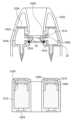
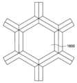
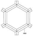
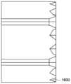
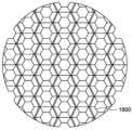
푸시 모드 발명의 다른 실시형태에서, 메시와 협력하는 멤브레인을 갖는 액적 전달 장치는 액적 전달 장치의 마우스피스 포트 전에 용기 조립체의 이젝션 채널에 위치된 층류 유동 요소를 더 포함한다. 바람직한 실시형태에서, 층류 유동 요소는 복수의 셀룰러 애퍼처들을 포함한다. 일부 실시형태에서, 층류 유동 요소는 복수의 셀룰러 애퍼처들을 규정하는 블레이드-형상 벽들을 포함한다. 다른 실시형태에서, 복수의 셀룰러 애퍼처들 중 하나 이상은 삼각형 프리즘 형상, 사각형 프리즘 형상, 오각형 프리즘 형상, 육각형 프리즘 형상, 칠각형 프리즘 형상, 또는 팔각형 프리즘 형상을 포함한다.In another embodiment of the push mode invention, the droplet delivery device having a membrane cooperating mesh further includes a laminar flow element located in the ejection channel of the vessel assembly prior to the mouthpiece port of the droplet delivery device. In a preferred embodiment, the laminar flow element includes a plurality of cellular apertures. In some embodiments, the laminar flow element includes blade-shaped walls defining a plurality of cellular apertures. In another embodiment, one or more of the plurality of cellular apertures includes a triangular prism shape, a square prism shape, a pentagonal prism shape, a hexagonal prism shape, a heptagonal prism shape, or an octagonal prism shape.
푸시 모드 발명의 다른 실시형태에서, 메시와 협력하는 멤브레인을 갖는 액적 전달 장치는 전원에 작동 가능하게 결합된 압력 센서와 같은 호흡 작동식 센서를 더 포함하며, 호흡 작동식 센서는 이젝션 채널 내에서 또는 이젝션 채널과 유체 연통하는 액적 전달 장치의 통로 내에서 미리 결정된 압력 변화를 감지할 때에 전자 트랜스듀서를 활성화시키도록 구성된다.In another embodiment of the push mode invention, the droplet delivery device having a membrane cooperating with the mesh further comprises a breath-activated sensor, such as a pressure sensor, operably coupled to a power source, the breath-activated sensor within the ejection channel or and configured to activate the electronic transducer upon detecting a predetermined change in pressure within a passageway of the droplet delivery device in fluid communication with the ejection channel.
푸시 모드 발명의 다른 실시형태에서, 메시와 협력하는 멤브레인을 갖는 액적 전달 장치는 팔라듐 니켈, 폴리테트라플루오로에틸렌, 및 폴리이미드 중 적어도 하나의 재료로 제조된 메시를 더 포함한다.In another embodiment of the push mode invention, the droplet delivery device having a membrane cooperating mesh further includes a mesh made of at least one material of palladium nickel, polytetrafluoroethylene, and polyimide.
푸시 모드 발명의 다른 실시형태에서, 메시와 협력하는 멤브레인을 갖는 액적 전달 장치는 폴리 에테르 케톤, 폴리에테르이미드, 폴리비닐리딘 플루오라이드, 초고분자량 폴리에틸렌, Ni, NiCo, Pd, Pt, NiPd, 및 금속 합금 중 적어도 하나의 재료로 제조된 메시를 더 포함한다. In another embodiment of the push mode invention, the droplet delivery device having a membrane cooperating with the mesh is made of polyether ketone, polyetherimide, polyvinylidine fluoride, ultrahigh molecular weight polyethylene, Ni, NiCo, Pd, Pt, NiPd, and metal. It further includes a mesh made of at least one material of the alloy.
다른 실시형태에서, 메시는 포토 리소그래피 및 등방성 및 이방성 에칭과 같은 반도체 프로세스들을 사용하여 형성된 홀 구조들을 갖는 규소, 규소 탄화물, 알루미늄 질화물 또는 게르마늄과 같은 단결정 또는 다결정 재료들로 제조될 수 있다. 포토리소그래피 및 등방성 및/또는 이방성 에칭들에 의해, 상이한 홀 형상들이 매우 높은 정밀도로 단결정 웨이퍼에서 형성될 수 있다. 스퍼터링을 이용하여, 필름들은 상이한 접촉각들로 표면 상에 디포짓팅될 수 있다. 표면 상에 형성되거나 디포짓팅된 얇은 층들은, 특정 실시형태들에서, 레이저 어블레이션에 의해 형성된 폴리머 메시 또는 갈바닉 디포지션에 의해 형성된 금속 메시 상에 디포짓팅된 필름보다 훨씬 더 양호한 접착을 가질 것이다. 이러한 더 양호한 접착은 단결정 웨이퍼들 "슬라이스들" 상의 표면들이 원자적으로 매끄럽고 접착제 또는 다른 재료들과의 기계적 결합을 용이하게 하기 위해 정확한 표면 거칠기를 생성하도록 에칭될 수 있기 때문이다. 규소 탄화물은 높은 강도 및 인성을 갖기 때문에 바람직한 재료이다. 푸시 모드 발명의 실시형태의 메시에서 단결정 웨이퍼 "슬라이스"로부터 홀 구조들을 제조하기 위해 반도체 프로세스들을 사용하는 중요한 이점은, 갈바닉 디포지션 또는 레이저 어블레이션으로부터 만들어진 메시를 사용하는 종래의 이젝터 플레이트들에서 본 바와 같은 변동 없이 홀들 및 표면 접촉각들이 정확할 것이라는 것이다.In other embodiments, the mesh may be made of single-crystalline or polycrystalline materials such as silicon, silicon carbide, aluminum nitride, or germanium with hole structures formed using semiconductor processes such as photolithography and isotropic and anisotropic etching. By photolithography and isotropic and/or anisotropic etchings, different hole shapes can be formed in a single crystal wafer with very high precision. Using sputtering, films can be deposited on a surface at different contact angles. Thin layers formed or deposited on a surface will, in certain embodiments, have much better adhesion than a film deposited on a polymer mesh formed by laser ablation or a metal mesh formed by galvanic deposition. This better adhesion is because the surfaces on the single crystal wafers “slices” are atomically smooth and can be etched to create the correct surface roughness to facilitate mechanical bonding with adhesives or other materials. Silicon carbide is a preferred material because it has high strength and toughness. A significant advantage of using semiconductor processes to fabricate hole structures from a single crystal wafer "slice" in the mesh of an embodiment of the push mode invention is that the mesh produced from galvanic deposition or laser ablation is superior to that seen in conventional ejector plates using a mesh made from galvanic deposition or laser ablation. The holes and surface contact angles will be accurate without any variations.
푸시 모드 발명의 다른 실시형태에서, 메시와 협력하는 멤브레인을 갖는 액적 전달 장치는 폴리에틸렌 나프탈레이트, 폴리에틸렌이민 및 폴리 에테르 케톤 중 적어도 하나의 재료로 제조된 멤브레인을 더 포함한다.In another embodiment of the push mode invention, the droplet delivery device having a membrane cooperating with the mesh further includes a membrane made of at least one material of polyethylene naphthalate, polyethyleneimine, and poly ether ketone.
푸시 모드 발명의 다른 실시형태에서, 메시와 협력하는 멤브레인을 갖는 액적 전달 장치는 금속 멤브레인, 금속화된 폴리머, 스레드화된 폴리머, 스레드화된 나일론, 폴리머 또는 금속으로 코팅된 스레드화된 폴리머, 폴리머 또는 금속으로 코팅된 스레드화된 나일론, 스레드화된 금속, 스레드화된 SiC, 스레드화된 흑연 복합체, 금속화된 흑연 복합체, 폴리머로 코팅된 흑연 복합체, 탄소 섬유로 충전된 폴리머 시트, 탄소 섬유로 충전된 폴리 에테르 케톤, SiC 섬유로 충전된 폴리머 시트, 세라믹 또는 금속 섬유로 충전된 폴리머 시트, ULPA 필터 매체, Nitto Denko Temic Grade 필터 매체, Nitto Denko 폴리머 시트, 폴리머 시트에 결합된 스레드화된 폴리머, 폴리 에테르 케톤 또는 폴리이미드에 결합된 나일론 직조, 폴리머 시트에 결합된 흑연 복합체, 금속화된 코팅으로 직조된 폴리머 섬유, 및 Al 또는 기상 증착된 Al 상에 스퍼터링된 나일론 중 적어도 하나의 재료로 제조된 멤브레인을 더 포함한다.In another embodiment of the push mode invention, the droplet delivery device having a membrane cooperating with the mesh is a metal membrane, a metalized polymer, a threaded polymer, a threaded nylon, a threaded polymer coated with a polymer or a metal, a polymer or threaded nylon coated with metal, threaded metal, threaded SiC, threaded graphite composite, metallized graphite composite, graphite composite coated with polymer, polymer sheet filled with carbon fiber, carbon fiber. Filled polyether ketone, polymer sheets filled with SiC fibers, polymer sheets filled with ceramic or metal fibers, ULPA filter media, Nitto Denko Temic Grade filter media, Nitto Denko polymer sheets, threaded polymer bonded to polymer sheets, Made of at least one material of nylon woven bonded to polyether ketone or polyimide, graphite composite bonded to polymer sheet, polymer fiber woven with metallized coating, and nylon sputtered on Al or vapor deposited Al. It further includes a membrane.
푸시 모드 발명의 다른 실시형태에서, 메시와 협력하는 멤브레인을 갖는 액적 전달 장치는 등급 5 티타늄 합금, 등급 23 티타늄 합금, 및 약 99% 이상의 순도의 티타늄 중 적어도 하나로 만들어진 팁 부분을 갖는 진동 부재에 결합된 PZT-기반 초음파 트랜스듀서를 더 포함한다. 특정 실시형태들에서, 진동 부재의 팁은 멤브레인의 마모를 감소시키고 멤브레인(및 또한 가능하게는 진동 부재의 팁 부분)의 수명 및 작동 일관성을 증가시키는 것을 돕기 위해 메시에 가장 가깝게 위치된 멤브레인의 외부 상부 표면에 대향하는 멤브레인의 하부 저부 표면에 접촉하도록 구성된 매끄러운 팁 표면을 제공하는 외부 층 상에 스퍼터링된 약 99% 이상의 순도의 티타늄을 포함한다.In another embodiment of the push mode invention, a droplet delivery device having a membrane cooperating with the mesh is coupled to a vibrating member having a tip portion made of at least one of
푸시 모드 발명의 다른 실시형태에서, 메시와 협력하는 멤브레인을 갖는 액적 전달 장치는, 진동 부재와 접촉하는 멤브레인의 하부 표면에 대향하는, 소수성 코팅을 갖는 멤브레인의 외부 표면을 더 포함한다.In another embodiment of the push mode invention, the droplet delivery device having a membrane cooperating with a mesh further comprises an outer surface of the membrane having a hydrophobic coating, opposite a lower surface of the membrane in contact with the vibrating member.
푸시 모드 발명의 다른 실시형태에서, 메시와 협력하는 멤브레인을 갖는 액적 전달 장치는 진동 부재와 접촉하는 멤브레인의 하부 표면에 대향하는, 친수성 코팅을 갖는 멤브레인의 외부 표면을 더 포함한다.In another embodiment of the push mode invention, the droplet transfer device having a membrane cooperating with a mesh further includes an outer surface of the membrane having a hydrophilic coating, opposite a lower surface of the membrane in contact with the vibrating member.
푸시 모드 발명의 다른 실시형태에서, 메시와 협력하는 멤브레인을 갖는 액적 전달 장치는 메시의 하나 이상의 표면 상에 친수성 코팅을 추가로 포함한다.In another embodiment of the push mode invention, the droplet delivery device having a membrane cooperating with the mesh further comprises a hydrophilic coating on one or more surfaces of the mesh.
푸시 모드 발명의 다른 실시형태에서, 메시와 협력하는 멤브레인을 갖는 액적 전달 장치는 메시의 하나 이상의 표면 상에 소수성 코팅을 포함하는 메시를 더 포함한다.In another embodiment of the push mode invention, the droplet delivery device having a membrane cooperating with the mesh further includes a mesh comprising a hydrophobic coating on one or more surfaces of the mesh.
푸시 모드 발명의 다른 실시형태에서, 메시와 협력하는 멤브레인을 갖는 액적 전달 장치는 메시의 제 1 표면 상의 소수성 코팅 및 메시의 제 2 표면 상의 친수성 코팅을 추가로 포함한다.In another embodiment of the push mode invention, the droplet delivery device having a membrane cooperating with the mesh further comprises a hydrophobic coating on a first surface of the mesh and a hydrophilic coating on a second surface of the mesh.
푸시 모드 발명의 다른 실시형태에서, 메시와 협력하는 멤브레인을 갖는 액적 전달 장치는 트랜스듀서에 의해 55,000 에어로졸-생성 활성화에 걸친 동작가능 수명을 갖는 멤브레인을 더 포함한다.In another embodiment of the push mode invention, the droplet delivery device having a membrane cooperating with the mesh further comprises a membrane having an operational lifetime of over 55,000 aerosol-generating activations by the transducer.
푸시 모드 발명의 다른 실시형태에서, 메시와 협력하는 멤브레인을 갖는 액적 전달 장치는 저장 동안 제거 가능한 알루미늄 처리된 폴리머 탭으로 덮인 저장조와 유체 연통하는 적어도 하나의 초소수성 벤트를 더 포함한다.In another embodiment of the push mode invention, the droplet delivery device having a membrane cooperating mesh further includes at least one superhydrophobic vent in fluid communication with the reservoir covered with an aluminized polymer tab that is removable during storage.
푸시 모드 발명의 다른 실시형태에서, 메시와 협력하는 멤브레인을 갖는 액적 전달 장치는 저장 동안 메시에 인접한 멤브레인의 외부 표면에 결합된 제거 가능한 알루미늄 처리된 폴리머 탭을 더 포함한다.In another embodiment of the push mode invention, the droplet delivery device having a membrane cooperating with a mesh further includes a removable aluminized polymer tab bonded to the outer surface of the membrane adjacent the mesh during storage.
푸시 모드 발명의 다른 실시형태에서, 메시와 협력하는 멤브레인을 갖는 액적 전달 장치는 유체를 갖는 저장조를 함께 수용하는 알루미늄 및/또는 알루미늄 코팅을 포함하는 밀봉된 패키징을 제거하는 사전-조립 단계를 포함하며, 바람직하게는 저장조는 또한 밀봉된 패키징에서의 저장을 위해 패키징되는 용기 조립체에 포함된다. 일부 실시형태에서, 밀봉된 패키징은 건조 질소, 아르곤 또는 산소를 포함하지 않는 다른 가스를 포함할 수 있다.In another embodiment of the push mode invention, a droplet delivery device having a membrane cooperating with a mesh includes a pre-assembly step of removing the sealed packaging comprising aluminum and/or aluminum coating together housing the reservoir with the fluid, , preferably the reservoir is also included in the container assembly which is packaged for storage in sealed packaging. In some embodiments, the sealed packaging may contain dry nitrogen, argon, or other gas that does not contain oxygen.
푸시 모드 발명의 다양한 실시형태에서, 메시와 협력하는 멤브레인을 갖는 액적 전달 장치는 구강 흡입 또는 비강 흡입에 사용될 수 있다. 마우스피스 포트는 그 특정 입 또는 코 흡입 사용 및 목적에 더 적합한 크기, 형상 및 재료를 포함할 수 있다.Push Mode In various embodiments of the invention, a droplet delivery device with a membrane cooperating with the mesh can be used for oral inhalation or nasal inhalation. The mouthpiece port may include a size, shape, and material more suitable for its particular oral or nasal inhalation use and purpose.
본 발명의 푸시 모드는 다음의 설명으로부터 더욱 명확하게 이해될 것이다:
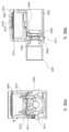
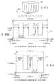
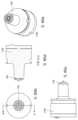
도 1a 는 본 개시의 실시형태에 따른 액적 전달 장치의 주요 부품들의 분해도이다.
도 1b 는 본 개시의 실시형태에 따른 액적 전달 장치의 주요 부품들의 단면도이다.
도 2 는 푸시 모드 II 로 지칭되는 본 개시의 일 실시형태에 따른 액적 전달 장치의 탄성 밀봉 링을 지지하는 스테인리스강 링에 결합된 메시의 개략도이다.
도 3 은 푸시 모드 I 으로 지칭되는 본 개시의 일 실시형태에 따른 액적 전달 장치의 내부 및 외부 태블릿 링 및 탄성 밀봉 링에 의해 지지되는 메시의 개략도이다.
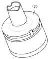
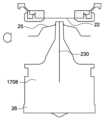
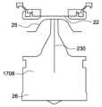
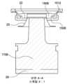
도 4 는 본 발명의 일 실시형태에 따른 액적 전달 장치의 이젝션 및 마우스피스 포트들의 특정 치수의 단면도를 도시한다.
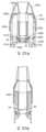
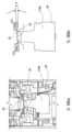
도 5 는 본 발명의 일 실시형태에 따른 2-부분 카트리지를 갖는 액적 전달 장치의 유체 유로의 단면도를 도시한다.
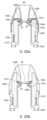
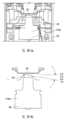
도 6a 및 도 6b 는 본 발명의 일 실시형태에 따른 2-부분 카트리지를 갖는 액적 전달 장치의 공기유동을 도시한다.
도 7a 및 도 7b 는 본 발명의 일 실시형태에서 (도 3 에 도시된 메시 지지부를 이용하는) 푸시 모드 I 액적 전달 장치의 주요 부품들의 분해 사시도를 도시한다.
도 8 은 본 발명의 일 실시형태에서 (도 3 에 도시된 메시 지지부를 이용하는) 푸시 모드 I 액적 전달 장치의 분해도를 도시한다.
도 9 는 본 발명의 일 실시형태에서 (도 3 에 도시된 메시 지지부를 이용하는) 푸시 모드 I 액적 전달 장치의 메시(22)를 포함하는 COC(환형 올레핀 공중합체) 링의 분리된 사시도를 도시한다.
도 10 은 본 발명의 일 실시형태에서 (도 3 에 중복되는) 푸시 모드 I 액적 전달 장치 메시 서스펜션 시스템의 개략도를 도시한다.
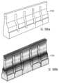
도 11 은 본 발명의 일 실시형태에서 (도 3 에 도시된 메시 지지부를 이용하는) 푸시 모드 I 액적 전달 장치의 브라켓의 각각의 좁은 측면 상에 위치된 벤트들을 포함하는 하부 이젝터 브라켓의 사시도를 도시한다.
도 12a 및 도 12b 는 본 개시의 일 실시형태에서 (도 2 에 도시된 메시 지지부를 이용하는) 푸시 모드 II 전달 장치의 주요 부품들의 분해 사시도를 도시한다.
도 13 은 본 개시의 일 실시형태에서 (도 2 에 도시된 메시 지지부를 이용하는) 푸시 모드 II 액적 전달 장치의 분해도를 도시한다.
도 14 는 본 개시의 일 실시형태에서 (도 2 에 또한 도시되는) 푸시 모드 II 액적 전달 장치 메시 서스펜션 시스템의 개략도를 도시한다.
도 15 는 본 개시의 일 실시형태에서 (도 2 에 도시된 메시 지지부를 이용하는) 푸시 모드 II 액적 전달 장치의 브라켓의 각각의 넓은 측면 상에 위치된 벤트들을 포함하는 하부 이젝터 브라켓의 사시도를 도시한다.
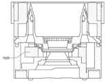
도 16 은 본 개시의 일 실시형태에서 (도 2 에 도시된 메시 지지부를 이용하는) 푸시 모드 II 액적 전달 장치의 하부 용기를 도시한다.
도 17 은 본 개시의 일 실시형태에서 (도 3 에 도시된 메시 지지부를 이용하는) 푸시 모드 I 액적 전달 장치의 하부 용기를 도시한다.
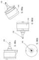
도 18 은 본 개시의 일 실시형태에 따른 액적 전달 장치의 진동 부재를 위한 로드 팁 설계의 사시도를 도시한다.
도 19 는 본 개시의 일 실시형태에 따른 액적 전달 장치의 진동 부재를 위한 링 팁 설계의 사시도를 도시한다.
도 20 은 본 개시의 일 실시형태에 따른 액적 전달 장치에서 긴 진동 부재를 갖는 단일 부품 카트리지 설계의 단면도를 도시한다.
도 21a 및 도 21b 는 본 개시의 일 실시형태에 따른 액적 전달 장치에서 짧은 진동 부재를 갖는 단일 부품 카트리지 설계의 단면도를 도시한다.
도 22a 및 도 22b 는 본 개시의 일 실시형태에 따른 액적 전달 장치에서 긴 진동 부재를 갖는 단일 부품 카트리지 대안 설계의 단면도를 도시한다.
도 23a 및 도 23b 는 본 개시의 일 실시형태에 따른 액적 전달 장치에서 짧은 진동 부재를 갖는 단일 부품 카트리지 대안 설계의 단면도를 도시한다.
도 24 는 본 개시의 일 실시형태에 따른 액적 전달 장치 내의 2-부분 카트리지 설계의 단면도 및 분리도를 도시한다.
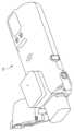
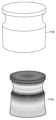
도 25 는 본 개시의 일 실시형태에 따라 제약 용도에 적합하고(그러나 다른 실시형태에서는 다른 용도일 수 있음) 멤브레인-구동 에어로졸화(즉, "푸시 모드 기능")를 활용하는 액적 전달 장치의 사시도를 도시한다.
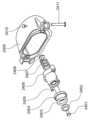
도 26 은 본 개시의 일 실시형태에 따라 제약 용도에 적합하고(그러나 다른 실시형태에서는 다른 용도일 수 있음) 멤브레인-구동 에어로졸화(즉, "푸시 모드 기능")를 활용하는 액적 전달 장치의 분해도를 도시한다.
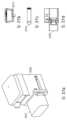
도 27a-27d 는 본 개시의 일 실시형태에 따라 제약 용도에 적합하고(그러나 다른 실시형태에서는 다른 용도일 수 있음) 멤브레인-구동 에어로졸화(즉, "푸시 모드 기능")를 활용하는 액적 전달 장치의 주요 부품들의 도면을 도시한다.
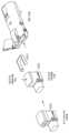
도 28a-28d 는 본 개시의 일 실시형태에 따라 제약 용도에 적합하고(그러나 다른 실시형태에서는 다른 용도일 수 있음) 멤브레인-구동 에어로졸화(즉, "푸시 모드 기능")를 활용하는 액적 전달 장치의 주요 부품들의 조립 도면을 도시한다.
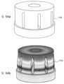
도 29 는 본 개시의 일 실시형태에 따라 제약 용도에 적합하고(그러나 다른 실시형태에서는 다른 용도일 수 있음) 멤브레인-구동 에어로졸화(즉, "푸시 모드 기능")를 활용하는 액적 전달 장치의 캡의 분해도를 도시한다.
도 30a 및 도 30b 는 본 개시의 일 실시형태에 따라 제약 용도에 적합하고(그러나 다른 실시형태에서는 다른 용도일 수 있음) 멤브레인-구동 에어로졸화(즉, "푸시 모드 기능")를 활용하는 액적 전달 장치의 유체 카트리지의 각각의 전방 및 측방 단면도를 도시한다.
도 31 은 본 개시의 일 실시형태에 따라 제약 용도에 적합하고(그러나 다른 실시형태에서는 다른 용도일 수 있음) 멤브레인-구동 에어로졸화(즉, "푸시 모드 기능")를 활용하는 액적 전달 장치의 진동 부재 인클로저의 단면도를 도시한다.
도 32 는 본 발명의 일 실시형태에 따라 제약 용도에 적합하고(그러나 다른 실시형태에서는 다른 용도일 수 있음) 도 14 에 도시된 메시 지지부의 구조 및 기능을 따르는 메시 서스펜션 시스템을 활용하는 이젝터 브라켓의 단면도를 도시한다.
도 33 은 본 발명의 일 실시형태에 따라 제약 용도에 적합하고(그러나 다른 실시형태에서는 다른 용도일 수 있음) 도 10 에 도시된 메시 지지부의 구조 및 기능을 따르는 메시 서스펜션 시스템을 활용하는 이젝터 브라켓의 단면도를 도시한다.
도 34a 및 34b 는 본 발명의 일 실시형태에 따라 제약 용도에 적합하고(그러나 다른 실시형태에서는 다른 용도일 수 있음) 이젝터 브라켓의 양측의 진동 부재 아래에 위치된 2개의 가열 요소를 갖는 멤브레인-구동 에어로졸화(즉, "푸시 모드 기능")를 활용하는 액적 전달 장치의 각각의 측방 및 전방 단면도를 도시한다.
도 35a-35c 는 본 개시의 일 실시형태에 따른 단일 부품 카트리지 설계를 갖는 저부 가열 요소를 갖는 액적 전달 장치를 위한 공기유동 경로의 단면도를 도시한다.
도 36 은 본 개시의 일 실시형태에 따른 단일 부품 카트리지 설계를 갖는 저부 가열 요소 및 스피커를 갖는 액적 전달 장치의 단면도를 도시한다.
도 37 은 본 개시의 일 실시형태에 따른 2-부분 카트리지 설계를 갖는 내부 가열 요소를 갖는 액적 전달 장치를 위한 공기유동 경로의 단면도를 도시한다.
도 38 은 본 개시의 일 실시형태에 따른 단일 부품 카트리지 설계를 갖는 내부 가열 요소를 갖는 액적 전달 장치를 위한 공기유동 경로의 단면도를 도시한다.
도 39 는 본 개시의 일 실시형태에 따른 단일 부품 카트리지 설계를 갖는 외부 가열 요소를 갖는 액적 전달 장치를 위한 공기유동 경로의 단면도를 도시한다.
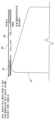
도 40 은 본 개시의 일 실시형태에 따른, 공기스트림의 온도를 일정하게 유지하고 또한 과열 및 사용자 부상을 피하기 위해 폐쇄 루프 시스템과 함께 사용되는 온도 센서를 포함하는 가열된 공기스트림을 갖는 액적 전달 장치의 단면도를 도시한다.
도 41a 및 도 41b 는 본 개시의 일 실시형태에 따른 슬라이딩 슬리브 및 관련 벤트를 통해 조절가능한 공기 저항을 갖는 액적 전달 장치의 도면을 도시한다.
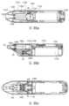
도 42 는 본 개시의 일 실시형태에 따라 비강 흡입에 적합하고 멤브레인-구동 에어로졸화(즉, "푸시 모드 기능")를 활용하는 액적 전달 장치의 길고 좁은 흡입 포트를 도시한다.
도 43 은 본 개시의 일 실시형태에 따라 비강 흡입에 적합하고 멤브레인-구동 에어로졸화(즉, "푸시 모드 기능")를 활용하는 액적 전달 장치의 더 짧은 버전의 흡입 포트를 도시한다.
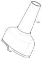
도 44a 및 도 44b 는 본 개시의 일 실시형태에 따라 비강 흡입에 적합하고 멤브레인-구동 에어로졸화(즉, "푸시 모드 기능")를 활용하는 액적 전달 장치의 제거 캡을 도시한다.
도 45 는 본 개시의 일 실시형태에 따라 멤브레인-구동 에어로졸화(즉, "푸시 모드 기능")를 활용하는 액적 전달 장치에 사용되는 액체가 유입될 수 있는 다수의 개구를 갖는 부착 플레이트를 갖는 메시를 도시한다.
도 46 은 본 개시의 일 실시형태에 따라 멤브레인-구동 에어로졸화(즉, "푸시 모드 기능")를 활용하는 액적 전달 장치에서 메시-멤브레인 영역 옆에 액체를 가로질러 배치된 2개의 평행 플레이트를 갖는 커패시턴스 카트리지의 단면도를 도시한다.
도 47a-47c 는 본 개시의 일 실시형태에 따른 멤브레인-구동 에어로졸화(즉, "푸시 모드 기능")를 활용하는 액적 전달 장치에서 직사각형 진동 부재 팁의 사시도(도 47a), 정면 평면도(도 47b) 및 측면 평면도(도 47c)를 도시한다.
도 48a-48c 는 본 개시의 일 실시형태에 따른 멤브레인-구동 에어로졸화(즉, "푸시 모드 기능")를 활용하는 액적 전달 장치에서 슬롯 또는 튜닝이 없는 고유 모드 진동 부재 팁 및 결과적인 진동 진폭 맵의 사시도(도 48a), 진동 진폭 맵 사시도(도 48b) 및 상부 진동 진폭 평면도(도 48c)를 도시한다.
도 49a-49c 는 본 개시의 일 실시형태에 따른 멤브레인-구동 에어로졸화(즉, "푸시 모드 기능")를 활용하는 액적 전달 장치에서 슬롯이 있는 고유 모드 진동 부재 팁 및 결과적인 진동 진폭 맵의 사시도(도 49a), 진동 진폭 맵 사시도(도 49b) 및 상부 진동 진폭 평면도(도 49c)를 도시한다.
도 50 은 본 개시의 일 실시형태에 따라 멤브레인-구동 에어로졸화(즉, "푸시 모드 기능")를 활용하는 액적 전달 장치 내의 컨투어드(contoured) 진동 부재를 도시한다.
도 51 은 본 개시의 일 실시형태에 따라 멤브레인-구동 에어로졸화(즉, "푸시 모드 기능")를 활용하는 액적 전달 장치 내의 플런저 진동 부재를 도시한다.
도 52 는 본 개시의 일 실시형태에 따라 멤브레인-구동 에어로졸화(즉, "푸시 모드 기능")를 활용하는 액적 전달 장치 내의 센서 캐리어 진동 부재를 도시한다.
도 53a 및 53b 는 본 개시의 일 실시형태에 따라 멤브레인-구동 에어로졸화(즉, "푸시 모드 기능")를 활용하는 액적 전달 장치에서의 스풀 진동 부재 및 그에 따른 진동 진폭 맵을 도시한다.
도 54a 및 54b 는 본 개시의 일 실시형태에 따라 멤브레인-구동 에어로졸화(즉, "푸시 모드 기능")를 활용하는 액적 전달 장치에서의 최적화된 원통형 진동 부재 및 그에 따른 진동 진폭 맵을 도시한다.
도 55a 및 55b 는 본 개시의 일 실시형태에 따라 멤브레인-구동 에어로졸화(즉, "푸시 모드 기능")를 활용하는 액적 전달 장치에서의 최적화되지 않은 슬롯형 원통형 진동 부재 및 그에 따른 진동 진폭 맵을 도시한다.
도 56a 및 56b 는 본 개시의 일 실시형태에 따라 멤브레인-구동 에어로졸화(즉, "푸시 모드 기능")를 활용하는 액적 전달 장치에서의 최적화된 바아 진동 부재 및 그에 따른 진동 진폭 맵을 도시한다.
도 57a 및 57b 는 본 개시의 일 실시형태에 따라 멤브레인-구동 에어로졸화(즉, "푸시 모드 기능")를 활용하는 액적 전달 장치에서의 최적화되지 않은 바아 진동 부재 및 그에 따른 진동 진폭 맵을 도시한다.
도 58a 및 도 58b 는 본 개시의 일 실시형태에 따른 멤브레인-구동 에어로졸화(즉, "푸시 모드 기능")를 활용하는 액적 전달 장치에서 부스터 진동 부재 및 그에 따른 진동 진폭 맵의 사시도(도 58a) 및 진동 진폭 단면도(도 58b)를 도시한다.
도 59a-59c 는 본 개시의 실시형태에 따른 액적 전달 장치의 트랜스듀서에 결합되는 대안적인 진동 부재의 사시도(도 59a), 상부 평면도(도 59b) 및 정면 평면도(도 59c)를 도시한다.
도 60a-60c 는 본 개시의 실시형태에 따른 액적 전달 장치의 트랜스듀서에 결합되는 대안적인 진동 부재의 사시도(도 60a), 상부 평면도(도 60b) 및 정면 평면도(도 60c)를 도시한다.
도 61a-61c 는 본 개시의 실시형태에 따른 액적 전달 장치의 트랜스듀서에 결합되는 대안적인 진동 부재의 사시도(도 61a), 상부 평면도(도 61b) 및 정면 평면도(도 61c)를 도시한다.
도 62a-62c 는 본 개시의 실시형태에 따른 액적 전달 장치의 트랜스듀서에 결합되는 대안적인 진동 부재의 사시도(도 62a), 상부 평면도(도 62b) 및 정면 평면도(도 62c)를 도시한다.
도 63a-63c 는 본 개시의 실시형태에 따른 액적 전달 장치의 트랜스듀서에 결합되는 대안적인 진동 부재의 사시도(도 63a), 상부 평면도(도 63b) 및 정면 평면도(도 63c)를 도시한다.
도 64a-64c 는 본 개시의 실시형태에 따른 액적 전달 장치의 트랜스듀서에 결합되는 대안적인 진동 부재의 사시도(도 64a), 상부 평면도(도 64b) 및 정면 평면도(도 64c)를 도시한다.
도 65a-65d 는 본 개시의 실시형태에 따라 액적 전달 장치의 트랜스듀서에 결합되는 대안적인 진동 부재의 사시도(도 65a), 상부 평면도(도 65b), 정면 평면도(도 65c) 및 도 65b 의 A-A를 따른 단면도(도 65d)를 도시한다.
도 66a-66c 는 본 개시의 실시형태에 따른 액적 전달 장치의 트랜스듀서에 결합되는 대안적인 진동 부재의 사시도(도 66a), 상부 평면도(도 66b) 및 정면 평면도(도 66c)를 도시한다.
도 67a-67c 는 본 개시의 실시형태에 따른 액적 전달 장치의 트랜스듀서에 결합되는 대안적인 진동 부재의 사시도(도 67a), 상부 평면도(도 67b) 및 정면 평면도(도 67c)를 도시한다.
도 68a-68d 는 본 개시의 실시형태에 따른 액적 전달 장치의 트랜스듀서에 결합되는 대안적인 진동 부재의 사시도(도 68a), 상부 평면도(도 68b) 및 정면 평면도(도 68c) 및 측면 평면도(도 68d)를 도시한다.
도 69a 및 도 69b 는 본 개시의 일 실시형태에 따른 액적 전달 장치의 트랜스듀서에 결합되는 대안적인 진동 부재의 사시도(도 69a) 및 측면 평면도(도 69b)를 도시한다.
도 70a-70c 는 본 개시의 실시형태에 따른 액적 전달 장치의 트랜스듀서에 결합되는 대안적인 진동 부재의 사시도(도 70a), 상부 평면도(도 70b) 및 정면 평면도(도 70c)를 도시한다.
도 71a-71c 는 본 개시의 실시형태에 따른 액적 전달 장치의 트랜스듀서에 결합되는 대안적인 진동 부재의 사시도(도 71a), 상부 평면도(도 71b) 및 정면 평면도(도 71c)를 도시한다.
도 72a-72c 는 본 개시의 실시형태에 따른 액적 전달 장치의 트랜스듀서에 결합되는 대안적인 진동 부재의 사시도(도 72a), 상부 평면도(도 72b) 및 정면 평면도(도 72c)를 도시한다.
도 73a-73c 는 본 개시의 실시형태에 따른 액적 전달 장치의 트랜스듀서에 결합되는 대안적인 진동 부재의 사시도(도 73a), 상부 평면도(도 73b) 및 정면 평면도(도 73c)를 도시한다.
도 74a-74c 는 본 개시의 실시형태에 따른 액적 전달 장치의 트랜스듀서에 결합되는 대안적인 진동 부재의 사시도(도 74a), 상부 평면도(도 74b) 및 정면 평면도(도 74c)를 도시한다.
도 75a-75c 는 본 개시의 실시형태에 따른 액적 전달 장치의 트랜스듀서에 결합되는 대안적인 진동 부재의 사시도(도 75a), 상부 평면도(도 75b) 및 정면 평면도(도 75c)를 도시한다.
도 76a-76c 는 본 개시의 실시형태에 따른 액적 전달 장치의 트랜스듀서에 결합되는 대안적인 진동 부재의 사시도(도 76a), 상부 평면도(도 76b) 및 정면 평면도(도 76c)를 도시한다.
도 77a-77d 는 본 개시의 실시형태에 따른 액적 전달 장치의 트랜스듀서에 결합되는 대안적인 진동 부재의 사시도(도 77a), 상부 평면도(도 77b) 및 정면 평면도(도 77c) 및 측면 평면도(도 77d)를 도시한다.
도 78a-78c 는 본 개시의 실시형태에 따른 액적 전달 장치의 트랜스듀서에 결합되는 대안적인 진동 부재의 사시도(도 78a), 상부 평면도(도 78b) 및 정면 평면도(도 78c)를 도시한다.
도 79a-79c 는 본 개시의 실시형태에 따른 액적 전달 장치의 트랜스듀서에 결합되는 대안적인 진동 부재의 사시도(도 79a), 상부 평면도(도 79b) 및 정면 평면도(도 79c)를 도시한다.
도 80a-80d 는 본 개시의 실시형태에 따른 액적 전달 장치의 트랜스듀서에 결합되는 대안적인 진동 부재의 사시도(도 80a), 상부 평면도(도 80b) 및 정면 평면도(도 80c) 및 측면 평면도(도 80d)를 도시한다.
도 81a-81d 는 본 개시의 실시형태에 따른 액적 전달 장치의 트랜스듀서에 결합되는 대안적인 진동 부재의 사시도(도 81a), 상부 평면도(도 81b) 및 정면 평면도(도 81c) 및 측면 평면도(도 81d)를 도시한다.
도 82a-82d 는 본 개시의 실시형태에 따른 액적 전달 장치의 트랜스듀서에 결합되는 대안적인 진동 부재의 사시도(도 82a), 상부 평면도(도 82b) 및 정면 평면도(도 82c) 및 측면 평면도(도 82d)를 도시한다.
도 83a-83c 는 본 개시의 실시형태에 따른 액적 전달 장치의 트랜스듀서에 결합되는 대안적인 진동 부재의 사시도(도 83a), 상부 평면도(도 83b) 및 정면 평면도(도 83c)를 도시한다.
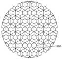
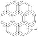
도 84a-84q 는 본 개시의 실시형태에 따른 액적 전달 장치의 용기 조립체의 층류 유동 요소들의 대안적인 구조들을 도시한다.
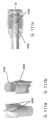
도 85a 는 본 개시의 실시형태에 따른 액적 전달 장치 내의 진동 부재 팁 부분을 포함하는 초음파 트랜스듀서를 도시한다.
도 85b 는 본 개시의 실시형태에 따른 액적 전달 장치 내의 멤브레인에 결합되는 도 85a 의 초음파 트랜스듀서의 부분 단면 평면도이다.
도 85c 및 도 85d 는 본 개시의 대안적인 실시형태에 따른 액적 전달 장치에서의 도 85b 의 초음파 트랜스듀서 및 멤브레인의 개략도이며, 메시는 도 85c 의 제 1 고정 기구 및 도 85d 의 제 2 고정 기구를 포함한다.
도 86a 는 본 개시의 실시형태에 따른 액적 전달 장치 내의 멤브레인에 결합되는 초음파 트랜스듀서의 부분 단면 평면도이다.
도 86b 및 도 86c 는 본 개시의 대안적인 실시형태에 따른 액적 전달 장치에서의 도 86a 의 초음파 트랜스듀서 및 멤브레인의 개략도이며, 메시는 도 86b 의 제 1 고정 기구 및 도 86c 의 제 2 고정 기구를 포함한다.
도 87 은 본 개시의 실시형태에 따른 경사진 멤브레인 및 메시를 통과하는 액적 전달 장치의 중심 축선으로부터 오프셋된 진동 부재 팁 부분을 갖는 초음파 트랜스듀서를 포함하는 액적 전달 장치의 부분 단면 평면도이다.
도 88a 는 본 개시의 실시형태에 따른 액적 전달 장치 내의 경사진 메시에 결합된 논-베벨 링-형상 진동 부재 팁 부분을 갖는 초음파 트랜스듀서의 부분 단면 평면도이다.
도 88b 는 본 개시의 실시형태에 따른 액적 전달 장치에서의 도 88a 의 초음파 트랜스듀서 및 멤브레인의 개략도이다.
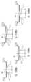
도 89a 는 본 개시의 실시형태에 따른 액적 전달 장치 내의 경사진 멤브레인에 결합된 베벨 링-형상 진동 부재 팁 부분을 갖는 초음파 트랜스듀서의 부분 단면 평면도이다.
도 89b 는 도 89a 에 도시된 초음파 트랜스듀서 및 메시와 협력하는 경사진 멤브레인을 도시한다.
도 89c 및 도 89d 는 본 개시의 대안적인 실시형태에 따른 액적 전달 장치에서의 도 89a 의 초음파 트랜스듀서 및 멤브레인의 개략도이며, 메시는 도 89c 의 제 1 고정 기구 및 도 89d 의 제 2 고정 기구를 포함한다.
도 89e 는 도 89a 의 베벨 링-형상 진동 부재 팁 부분을 갖는 초음파 트랜스듀서를 도시한다.
도 90a 는 본 개시의 실시형태에 따른 액적 전달 장치 내의 메시와 접촉하고 멤브레인에 결합된 논-베벨 링-형상 진동 부재 팁 부분을 갖는 초음파 트랜스듀서의 부분 단면 평면도이다.
도 90b 는 본 개시의 실시형태에 따른 액적 전달 장치에서의 도 90a 의 초음파 트랜스듀서 및 멤브레인의 개략도이다. 이 실시형태는 푸시 모드 I 또는 II 중 어느 하나의 메시 캐리어와 함께 사용될 수 있다.
도 91a 는 본 개시의 실시형태에 따른 액적 전달 장치에서 메시와 멤브레인 사이의 공간을 갖는 경사진 멤브레인에 결합된 베벨 링-형상 진동 부재 팁 부분을 갖는 초음파 트랜스듀서의 부분 단면 평면도이다.
도 91b 는 본 개시의 실시형태에 따른 액적 전달 장치에서의 도 91a 의 초음파 트랜스듀서 및 멤브레인의 개략도이다. 이 실시형태는 푸시 모드 I 또는 II 의 메시 캐리어와 함께 사용될 수 있다.
도 92 는 본 개시의 실시형태에 따른 액적 전달 장치에서 메시와 멤브레인 사이의 공간을 갖는 멤브레인에 결합된 논-베벨 링-형상 진동 부재 팁 부분을 갖는 초음파 트랜스듀서의 개략도이다. 이 실시형태는 푸시 모드 I 또는 II 의 메시 캐리어와 함께 사용될 수 있다.
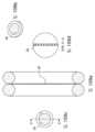
도 93a 및 도 93b 는 본 개시의 실시형태에 따라 멤브레인 및 메시와 함께 넓고 평평한 진동 부재 팁 부분을 갖는 초음파 트랜스듀서의 분리 사시도(도 93a)와 도 93a 의 선 A-A 를 따른 단면도(도 93b)를 도시한 액적 전달 장치의 초음파 트랜스듀서의 개략도이다.
도 94a-94d 는 본 개시의 실시형태에 따라 멤브레인 및 메시와 함께 넓은 링-형상의 팁 부분을 갖는 초음파 트랜스듀서의 도 94a 의 B-B 선을 따른 초음파 트랜스듀서의 단면 분리도(도 94b), 분리도(도 94c) 및 도 94c 의 A-A 선을 따른 단면도(도 94d)를 도시한 액적 전달 장치(도 94)의 개략도이다.
도 95 는 본 개시의 일 실시형태에서 알루미늄화된 폴리머 탭의 개략적인 블록도이다.
도 96a-96d 는 본 개시의 실시형태에 따른 액적 전달 장치의 멤브레인의 사시도이다.
도 97a 및 도 97b 는 본 개시의 일 실시형태에 따른 액적 전달 장치 내의 팁 부분을 갖는 진동 부재에 결합된 트랜스듀서 및 멤브레인에 대해 스테인리스강 환형체에 의해 상승 위치에서 지지되는 폴리머 메시의 단면도(도 97a) 및 확대도(도 97b)를 도시한다.
도 98a 및 도 98b 는 본 개시의 일 실시형태에 따른 액적 전달 장치 내의 팁 부분을 갖는 진동 부재에 결합된 트랜스듀서 및 멤브레인에 대해 스테인리스강 환형체에 의해 하강 위치에서 지지되는 폴리머 메시의 단면도(도 98a) 및 확대도(도 98b)를 도시한다.
도 99a 및 도 99b 는 본 개시의 일 실시형태에 따른 액적 전달 장치에서 팁 부분을 갖는 진동 부재에 결합된 멤브레인 및 트랜스듀서에 대해 제 1 스테인리스강 환형체에 의해 상승 위치에서 지지되고, 예컨대 접착제 또는 접합제로 접합함으로써 제 1 환형체의 상부에 결합된 보강재로서의 제 2 스테인리스강 환형체를 갖는 폴리머 메시의 단면도(도 99a) 및 확대도(도 99b)를 도시한다.
도 100a 및 도 100b 는 본 개시의 일 실시형태에 따른 액적 전달 장치에서 팁 부분을 갖는 진동 부재에 결합된 멤브레인 및 트랜스듀서에 대해 제 1 스테인리스강 환형체에 의해 하강 위치에서 지지되고, 예컨대 접착제 또는 접합제로 접합함으로써 제 1 환형체의 하부에 결합된 보강재로서의 제 2 스테인리스강 환형체를 갖는 폴리머 메시의 단면도(도 100a) 및 확대도(도 100b)를 도시한다.
도 101a-101c 는 본 개시의 실시형태에 따른 액적 전달 장치 내의 진동 부재에 결합된 멤브레인 및 트랜스듀서에 대해 링형 지지부의 플라스틱 요소들을 갖는(그리고 금속 환형체가 없는) 들쭉날쭉한 지지부(도 101c)를 통해 상승 위치(도 101a), 하강 위치(도 101b)에서 지지되는 폴리머 메시의 단면도를 도시한다.
도 102a-c 는 도 101a의 확대도(도 102a), 도 101b의 확대도(도 102b) 및 도 101c의 확대로(도 102c)를 도시한다.
도 103a 및 도 103b 는 본 개시의 실시형태에 따른 액적 전달 장치 내의 폴리머 메시와 진동 부재 팁 부분을 덮는 멤브레인 사이의 폴리머 메시 아래에 놓인 플레이트 내의 개구들을 갖는 스테인리스강 모세관 플레이트 및 폴리머 메시의 단면도(도 103a) 및 확대도(도 103b)를 도시한다.
도 103c 는 도 103a 및 103b 에 도시된 폴리머 메시의 개략적인 상부 평면도이다.
도 103d 는 도 103a 및 103b 에 도시된 스테인레스강 모세관 플레이트의 개략적인 상부 평면도이다.
도 104 는 폴리머 메시 및 모세관 플레이트의 개략도를 도시하며, 모세관 플레이트는 진동 부재를 덮는 (또한 PEN 재료로 제조된) 멤브레인과 같은 PEN 재료로 제조되고, 본 개시의 일 실시형태에 따른 액적 전달 장치에서의 모세관 플레이트와 메시 사이에 (금속, 세라믹 또는 플라스틱과 같은) 스페이서를 추가로 포함한다.
도 105a 및 도 105b 는 본 개시의 실시형태에 따른 액적 전달 장치에서 팁 부분을 갖는 진동 부재에 결합된 트랜스듀서 및 멤브레인에 대해 폴리머 메시에 결합되는 환형체의 중심 부분을 향해 아래로 그리고 위로 스테인리스강 환형체에 결합되는 플라스틱 또는 실리콘 링-형상 브라켓(d)을 갖는 폴리머 메시의 단면도(도 105a) 및 확대도(도 105b)를 도시한다.
도 106a 및 도 106 b 는 본 개시의 실시형태에 따른 액적 전달 장치 내의 팁 부분을 갖는 진동 부재에 결합된 트랜스듀서 및 멤브레인에 대해 폴리머 메시에 결합되는 환형체의 플라스틱 또는 실리콘 링-형상 브라켓 중심 부분을 갖는 폴리머 메시의 단면도(도 106a) 및 확대도(도 106b)를 도시한다.
도 107a-107d 는 이중-강화 스테인리스강 환형체들에 결합된 플라스틱 또는 실리콘 링-형상 브라켓을 갖는 폴리머 메시의 단면도를 도시하며(도 99 및 도 100과 유사함), 본 개시의 실시형태에 따른 액적 전달 장치에서 팁 부분을 갖는 진동 부재에 결합된 멤브레인 및 트랜스듀서에 대해 폴리머 메시는 추가 연장 상부 강화부에 의해 상승되고(도 107a), 폴리머 메시는 추가 연장 상부 강화부에 의해 상승되고(도 107b), 폴리머 메시는 연장 하부 강화부에 의해 하강되고(도 107c), 폴리머 메시는 추가 연장 하부 강화부에 의해 하강된다(도 107d).
도 108a-108d 는 도 107a의 확대도(도 108a), 도 107b의 확대도(도 108b), 도 107c의 확대도(도 108c) 및 도 107d의 확대도(도 108d)를 도시한다.
도 109a 내지 도 109d 는 본 개시의 일 실시형태에 따른 액적 전달 장치의 메시에서, 의사구면(pseudospherical)과 같은 매끄러운 개구들(메시를 완전히 통해 개구들을 도시하도록 의도된 도 109d 의 확대 단면도)의 정확한 제조를 제공하기 위해 반도체 기술로 처리된 링-구조화된 지지부들 사이의 결정질 실리콘 또는 실리콘 카바이드 "웨이퍼"-유형 메시의 단면도(도 109a), 사시도(도 109b), 상부 평면도(도 109c) 및 도 109c의 C-C선을 따른 단면 확대도(도 109d)를 도시한다.
도 110 은 본 개시의 일 실시형태에 따른 액적 전달 장치에서 메시의 두께를 통해 더 크게 시작하고 이어서 개구들 내의 더 작은 애퍼처들로 종료되거나 마무리되는(그리고 또한 반도체 기술 처리에 의해 경사질 수 있는) 웰-타입 개구들을 갖는 결정질 실리콘 또는 실리콘 카바이드 "웨이퍼"-유형 메시의 단면도 및 확대도를 도시한다.
도 111a-111c 는 본 개시의 실시형태에 따른 핀들을 갖는 배플과 흡수기의 제 1 단부의 사시도(도 111a), 핀들을 갖는 배플의 제 2 대향 단부의 사시도(도 111b), 및 핀들을 갖는 배플을 포함하는 메시를 갖는 이젝터 플레이트 및 액적 전달 장치의 부분 개략도를 도시한다.
도 112 는 본 개시의 실시형태에 따른 배플이 없는 공기유동 디렉터를 포함하는 액적 전달 장치의 공기유동 경로의 유선형 속도장 그래픽 맵이다.
도 113 은 본 개시의 실시형태에 따른 공기유동 디렉터가 없고 위킹 재료를 갖는 배플을 포함하는 액적 전달 장치의 공기유동 경로의 유선형 속도장 그래픽 맵이다.
도 114 는 본 개시의 실시형태에 따른 공기유동 디렉터를 또한 포함하고 위킹 재료를 갖는 배플을 포함하는 액적 전달 장치의 공기유동 경로의 유선형 속도장 그래픽 맵이다.The push mode of the present invention will be more clearly understood from the following description:
1A is an exploded view of main components of a droplet delivery device according to an embodiment of the present disclosure.
1B is a cross-sectional view of main components of a droplet delivery device according to an embodiment of the present disclosure.
Figure 2 is a schematic diagram of a mesh coupled to a stainless steel ring supporting an elastic sealing ring of a droplet delivery device according to an embodiment of the present disclosure, referred to as Push Mode II.
Figure 3 is a schematic diagram of a mesh supported by inner and outer tablet rings and elastic sealing rings of a droplet delivery device according to one embodiment of the present disclosure, referred to as Push Mode I.
Figure 4 shows a cross-sectional view of certain dimensions of the ejection and mouthpiece ports of a droplet delivery device according to one embodiment of the invention.
Figure 5 shows a cross-sectional view of the fluid flow path of a droplet delivery device with a two-part cartridge according to one embodiment of the invention.
6A and 6B show airflow in a droplet delivery device with a two-part cartridge according to one embodiment of the invention.
Figures 7A and 7B show exploded perspective views of major components of a push mode I droplet transfer device (using the mesh support shown in Figure 3) in one embodiment of the invention.
Figure 8 shows an exploded view of a push mode I droplet delivery device (using the mesh support shown in Figure 3) in one embodiment of the invention.
Figure 9 shows an isolated perspective view of a COC (cyclic olefin copolymer)
Figure 10 shows a schematic diagram of a push mode I droplet delivery device mesh suspension system (overlapping with Figure 3) in one embodiment of the invention.
Figure 11 shows a perspective view of a lower ejector bracket including vents located on each narrow side of the bracket of a push mode I droplet transfer device (using the mesh support shown in Figure 3) in one embodiment of the invention. .
Figures 12A and 12B show exploded perspective views of major components of a push mode II delivery device (using the mesh support shown in Figure 2) in one embodiment of the present disclosure.
FIG. 13 shows an exploded view of a push mode II droplet delivery device (using the mesh support shown in FIG. 2) in one embodiment of the present disclosure.
Figure 14 shows a schematic diagram of a push mode II droplet delivery device mesh suspension system (also shown in Figure 2) in one embodiment of the present disclosure.
FIG. 15 shows a perspective view of a lower ejector bracket including vents located on each broad side of the bracket of a push mode II droplet transfer device (using the mesh support shown in FIG. 2) in one embodiment of the present disclosure. .
FIG. 16 shows the lower container of a push mode II droplet delivery device (using the mesh support shown in FIG. 2) in one embodiment of the present disclosure.
FIG. 17 shows the lower container of a push mode I droplet transfer device (using the mesh support shown in FIG. 3) in one embodiment of the present disclosure.
Figure 18 shows a perspective view of a rod tip design for an oscillating member of a droplet delivery device according to one embodiment of the present disclosure.
Figure 19 shows a perspective view of a ring tip design for an oscillating member of a droplet delivery device according to one embodiment of the present disclosure.
Figure 20 shows a cross-sectional view of a single-piece cartridge design with an elongated oscillating member in a droplet delivery device according to one embodiment of the present disclosure.
21A and 21B show cross-sectional views of a single-piece cartridge design with a short oscillating member in a droplet delivery device according to one embodiment of the present disclosure.
22A and 22B show cross-sectional views of a single-piece cartridge alternative design with an elongated oscillating member in a droplet delivery device according to one embodiment of the present disclosure.
23A and 23B show cross-sectional views of a single-piece cartridge alternative design with a short oscillating member in a droplet delivery device according to one embodiment of the present disclosure.
Figure 24 shows a cross-sectional and separated view of a two-part cartridge design within a droplet delivery device according to one embodiment of the present disclosure.
Figure 25 is a perspective view of a droplet delivery device utilizing membrane-driven aerosolization (i.e., "push mode functionality") suitable for pharmaceutical applications (but may be for other applications in other embodiments) according to one embodiment of the present disclosure. shows.
FIG. 26 is an exploded view of a droplet delivery device utilizing membrane-driven aerosolization (i.e., “push mode functionality”) suitable for pharmaceutical applications (but may be for other applications in other embodiments) according to one embodiment of the present disclosure. shows.
27A-27D show a droplet delivery device utilizing membrane-driven aerosolization (i.e., “push mode functionality”) and suitable for pharmaceutical applications (but may have other applications in other embodiments) according to one embodiment of the present disclosure. A drawing of the main parts is shown.
28A-28D show a droplet delivery device utilizing membrane-driven aerosolization (i.e., “push mode functionality”) and suitable for pharmaceutical applications (but may have other applications in other embodiments) according to one embodiment of the present disclosure. Shows an assembly drawing of the main parts.
29 shows a cap of a droplet delivery device utilizing membrane-driven aerosolization (i.e., “push mode functionality”) suitable for pharmaceutical applications (but may be for other applications in other embodiments) according to one embodiment of the present disclosure. An exploded view is shown.
30A and 30B show droplet delivery utilizing membrane-driven aerosolization (i.e., “push mode functionality”) suitable for pharmaceutical applications (but may be for other applications in other embodiments) according to one embodiment of the present disclosure. Shown are front and side cross-sectional views, respectively, of the fluid cartridge of the device.
31 shows the oscillation of a droplet delivery device utilizing membrane-driven aerosolization (i.e., “push mode functionality”) and suitable for pharmaceutical applications (but may be for other applications in other embodiments) according to one embodiment of the present disclosure. A cross-sectional view of the member enclosure is shown.
FIG. 32 illustrates an ejector bracket utilizing a mesh suspension system suitable for pharmaceutical applications (but may be for other applications in other embodiments) according to one embodiment of the invention and following the structure and function of the mesh support shown in FIG. 14 . A cross-sectional view is shown.
FIG. 33 illustrates an ejector bracket utilizing a mesh suspension system suitable for pharmaceutical applications (but may be for other applications in other embodiments) according to one embodiment of the invention and following the structure and function of the mesh support shown in FIG. 10 . A cross-sectional view is shown.
34A and 34B show a membrane-actuated device suitable for pharmaceutical applications (but may have other applications in other embodiments) according to one embodiment of the invention and having two heating elements positioned below the oscillating members on either side of the ejector bracket. Respective lateral and front cross-sectional views of a droplet delivery device utilizing aerosolization (i.e., “push mode functionality”) are shown.
Figures 35A-35C show cross-sectional views of the airflow path for a droplet delivery device with a bottom heating element with a single component cartridge design according to one embodiment of the present disclosure.
Figure 36 shows a cross-sectional view of a droplet delivery device with a bottom heating element and speaker with a single-piece cartridge design according to one embodiment of the present disclosure.
Figure 37 shows a cross-sectional view of an airflow path for a droplet delivery device with an internal heating element with a two-part cartridge design according to one embodiment of the present disclosure.
Figure 38 shows a cross-sectional view of an airflow path for a droplet delivery device with an internal heating element with a single component cartridge design according to one embodiment of the present disclosure.
Figure 39 shows a cross-sectional view of an airflow path for a droplet delivery device with an external heating element with a single component cartridge design according to one embodiment of the present disclosure.
40 shows a droplet delivery device with a heated airstream including a temperature sensor used in conjunction with a closed loop system to maintain the temperature of the airstream constant and avoid overheating and user injury, according to one embodiment of the present disclosure. A cross-sectional view is shown.
41A and 41B show diagrams of a droplet delivery device with adjustable air resistance through a sliding sleeve and associated vents according to one embodiment of the present disclosure.
42 illustrates the long, narrow inhalation port of a droplet delivery device suitable for nasal inhalation and utilizing membrane-driven aerosolization (i.e., “push mode functionality”) according to one embodiment of the present disclosure.
Figure 43 shows a shorter version of the inhalation port of a droplet delivery device suitable for nasal inhalation and utilizing membrane-driven aerosolization (i.e., “push mode functionality”) according to one embodiment of the present disclosure.
44A and 44B illustrate a removal cap of a droplet delivery device suitable for nasal inhalation and utilizing membrane-driven aerosolization (i.e., “push mode functionality”), according to one embodiment of the present disclosure.
45 shows a mesh having an attachment plate having multiple openings through which liquid may enter as used in a droplet delivery device utilizing membrane-driven aerosolization (i.e., “push mode functionality”) according to one embodiment of the present disclosure. shows.
46 shows a droplet delivery device utilizing membrane-driven aerosolization (i.e., “push mode functionality”) in accordance with one embodiment of the present disclosure, with two parallel plates positioned across the liquid next to the mesh-membrane region. A cross-sectional view of the capacitance cartridge is shown.
47A-47C show a perspective view (FIG. 47A) and a front plan view (FIG. 47B) of a rectangular oscillating member tip in a droplet delivery device utilizing membrane-driven aerosolization (i.e., “push mode functionality”) according to one embodiment of the present disclosure. ) and side plan view (Figure 47c).
48A-48C show eigenmode vibration member tips without slots or tuning and resulting vibration amplitude maps in a droplet delivery device utilizing membrane-driven aerosolization (i.e., “push mode functionality”) according to one embodiment of the present disclosure. shows a perspective view (Figure 48a), a perspective view of the vibration amplitude map (Figure 48b), and a top view of the top vibration amplitude (Figure 48c).
49A-49C are perspective views of a slotted eigenmode oscillating member tip and resulting oscillation amplitude map in a droplet delivery device utilizing membrane-driven aerosolization (i.e., “push mode functionality”) according to one embodiment of the present disclosure. (FIG. 49a), a perspective view of the vibration amplitude map (FIG. 49b), and a top view of the vibration amplitude (FIG. 49c).
FIG. 50 illustrates a contoured oscillating member in a droplet delivery device utilizing membrane-driven aerosolization (i.e., “push mode functionality”) according to one embodiment of the present disclosure.
FIG. 51 illustrates a plunger oscillating member in a droplet delivery device utilizing membrane-driven aerosolization (i.e., “push mode functionality”) according to one embodiment of the present disclosure.
FIG. 52 illustrates a sensor carrier oscillating member in a droplet delivery device utilizing membrane-driven aerosolization (i.e., “push mode functionality”) according to one embodiment of the present disclosure.
53A and 53B illustrate the absence of spool vibration and the resulting vibration amplitude map in a droplet delivery device utilizing membrane-driven aerosolization (i.e., “push mode functionality”) according to one embodiment of the present disclosure.
Figures 54A and 54B illustrate an optimized cylindrical oscillating member and resulting oscillation amplitude map in a droplet delivery device utilizing membrane-driven aerosolization (i.e., “push mode functionality”) according to one embodiment of the present disclosure.
55A and 55B show a non-optimized slotted cylindrical oscillating member and resulting oscillation amplitude map in a droplet delivery device utilizing membrane-driven aerosolization (i.e., “push mode functionality”) according to one embodiment of the present disclosure. It shows.
Figures 56A and 56B illustrate optimized bar oscillation elements and resulting oscillation amplitude maps in a droplet delivery device utilizing membrane-driven aerosolization (i.e., “push mode functionality”) according to one embodiment of the present disclosure.
57A and 57B illustrate non-optimized bar vibration elements and resulting vibration amplitude maps in a droplet delivery device utilizing membrane-driven aerosolization (i.e., “push mode functionality”) according to one embodiment of the present disclosure. .
FIGS. 58A and 58B are perspective views of a booster oscillation element and resulting oscillation amplitude map in a droplet delivery device utilizing membrane-driven aerosolization (i.e., “push mode functionality”) according to one embodiment of the present disclosure (FIG. 58A) and vibration amplitude cross-section (FIG. 58B).
Figures 59A-59C show a perspective view (Figure 59A), a top plan view (Figure 59B), and a front plan view (Figure 59C) of an alternative vibrating member coupled to a transducer of a droplet delivery device according to an embodiment of the present disclosure.
Figures 60A-60C show a perspective view (Figure 60A), a top plan view (Figure 60B), and a front plan view (Figure 60C) of an alternative vibrating member coupled to a transducer of a droplet delivery device according to an embodiment of the present disclosure.
Figures 61A-61C show a perspective view (Figure 61A), a top plan view (Figure 61B), and a front plan view (Figure 61C) of an alternative vibrating member coupled to a transducer of a droplet delivery device according to an embodiment of the present disclosure.
Figures 62A-62C show a perspective view (Figure 62A), a top plan view (Figure 62B), and a front plan view (Figure 62C) of an alternative vibrating member coupled to a transducer of a droplet delivery device according to an embodiment of the present disclosure.
Figures 63A-63C show a perspective view (Figure 63A), a top plan view (Figure 63B), and a front plan view (Figure 63C) of an alternative vibrating member coupled to a transducer of a droplet delivery device according to an embodiment of the present disclosure.
Figures 64A-64C show a perspective view (Figure 64A), a top plan view (Figure 64B), and a front plan view (Figure 64C) of an alternative oscillating member coupled to a transducer of a droplet delivery device according to an embodiment of the present disclosure.
65A-65D show a perspective view (FIG. 65A), a top plan view (FIG. 65B), a front plan view (FIG. 65C), and AA of FIG. 65B of an alternative vibrating member coupled to a transducer of a droplet delivery device according to an embodiment of the present disclosure. A cross-sectional view along (FIG. 65d) is shown.
Figures 66A-66C show a perspective view (Figure 66A), a top plan view (Figure 66B), and a front plan view (Figure 66C) of an alternative oscillating member coupled to a transducer of a droplet delivery device according to an embodiment of the present disclosure.
Figures 67A-67C show a perspective view (Figure 67A), a top plan view (Figure 67B), and a front plan view (Figure 67C) of an alternative oscillating member coupled to a transducer of a droplet delivery device according to an embodiment of the present disclosure.
68A-68D show a perspective view (FIG. 68A), a top plan view (FIG. 68B) and a front plan view (FIG. 68C) and a side plan view (FIG. 68A) of an alternative vibrating member coupled to a transducer of a droplet delivery device according to an embodiment of the present disclosure. 68d) is shown.
Figures 69A and 69B show a perspective view (Figure 69A) and a side plan view (Figure 69B) of an alternative vibrating member coupled to a transducer of a droplet delivery device according to one embodiment of the present disclosure.
Figures 70A-70C show a perspective view (Figure 70A), a top plan view (Figure 70B), and a front plan view (Figure 70C) of an alternative vibrating member coupled to a transducer of a droplet delivery device according to an embodiment of the present disclosure.
Figures 71A-71C show a perspective view (Figure 71A), a top plan view (Figure 71B), and a front plan view (Figure 71C) of an alternative oscillating member coupled to a transducer of a droplet delivery device according to an embodiment of the present disclosure.
Figures 72A-72C show a perspective view (Figure 72A), a top plan view (Figure 72B), and a front plan view (Figure 72C) of an alternative vibrating member coupled to a transducer of a droplet delivery device according to an embodiment of the present disclosure.
Figures 73A-73C show a perspective view (Figure 73A), a top plan view (Figure 73B), and a front plan view (Figure 73C) of an alternative vibrating member coupled to a transducer of a droplet delivery device according to an embodiment of the present disclosure.
Figures 74A-74C show a perspective view (Figure 74A), a top plan view (Figure 74B), and a front plan view (Figure 74C) of an alternative oscillating member coupled to a transducer of a droplet delivery device according to an embodiment of the present disclosure.
Figures 75A-75C show a perspective view (Figure 75A), a top plan view (Figure 75B), and a front plan view (Figure 75C) of an alternative oscillating member coupled to a transducer of a droplet delivery device according to an embodiment of the present disclosure.
Figures 76A-76C show a perspective view (Figure 76A), a top plan view (Figure 76B), and a front plan view (Figure 76C) of an alternative oscillating member coupled to a transducer of a droplet delivery device according to an embodiment of the present disclosure.
77A-77D show a perspective view (FIG. 77A), a top plan view (FIG. 77B) and a front plan view (FIG. 77C) and a side plan view (FIG. 77A) of an alternative vibrating member coupled to a transducer of a droplet delivery device according to an embodiment of the present disclosure. 77d) is shown.
Figures 78A-78C show a perspective view (Figure 78A), a top plan view (Figure 78B), and a front plan view (Figure 78C) of an alternative oscillating member coupled to a transducer of a droplet delivery device according to an embodiment of the present disclosure.
Figures 79A-79C show a perspective view (Figure 79A), a top plan view (Figure 79B), and a front plan view (Figure 79C) of an alternative oscillating member coupled to a transducer of a droplet delivery device according to an embodiment of the present disclosure.
80A-80D show a perspective view (FIG. 80A), a top plan view (FIG. 80B) and a front plan view (FIG. 80C) and a side plan view (FIG. 80C) of an alternative vibrating member coupled to a transducer of a droplet delivery device according to an embodiment of the present disclosure. 80d) is shown.
81A-81D show a perspective view (FIG. 81A), a top plan view (FIG. 81B), a front plan view (FIG. 81C), and a side plan view (FIG. 81C) of an alternative vibrating member coupled to a transducer of a droplet delivery device according to an embodiment of the present disclosure. 81d) is shown.
82A-82D show a perspective view (FIG. 82A), a top plan view (FIG. 82B), a front plan view (FIG. 82C), and a side plan view (FIG. 82C) of an alternative vibrating member coupled to a transducer of a droplet delivery device according to an embodiment of the present disclosure. 82d) is shown.
Figures 83A-83C show a perspective view (Figure 83A), a top plan view (Figure 83B), and a front plan view (Figure 83C) of an alternative vibrating member coupled to a transducer of a droplet delivery device according to an embodiment of the present disclosure.
Figures 84A-84Q illustrate alternative structures of laminar flow elements of a vessel assembly of a droplet delivery device according to an embodiment of the present disclosure.
FIG. 85A shows an ultrasonic transducer including an oscillating member tip portion in a droplet delivery device according to an embodiment of the present disclosure.
FIG. 85B is a partial cross-sectional top view of the ultrasonic transducer of FIG. 85A coupled to a membrane in a droplet delivery device according to an embodiment of the present disclosure.
FIGS. 85C and 85D are schematic diagrams of the ultrasonic transducer and membrane of FIG. 85B in a droplet delivery device according to an alternative embodiment of the present disclosure, with the mesh supporting the first fastening mechanism of FIG. 85C and the second fastening mechanism of FIG. 85D. Includes.
Figure 86A is a partial cross-sectional top view of an ultrasonic transducer coupled to a membrane in a droplet delivery device according to an embodiment of the present disclosure.
FIGS. 86B and 86C are schematic diagrams of the ultrasonic transducer and membrane of FIG. 86A in a droplet delivery device according to an alternative embodiment of the present disclosure, with the mesh supporting the first fastening mechanism of FIG. 86B and the second fastening mechanism of FIG. 86C. Includes.
Figure 87 is a partial cross-sectional top view of a droplet delivery device including an ultrasonic transducer with an oscillating member tip portion offset from the central axis of the droplet delivery device passing through an inclined membrane and mesh according to an embodiment of the present disclosure.
Figure 88A is a partial cross-sectional top view of an ultrasonic transducer with a non-beveled ring-shaped oscillating member tip portion coupled to an inclined mesh in a droplet delivery device according to an embodiment of the present disclosure.
FIG. 88B is a schematic diagram of the ultrasonic transducer and membrane of FIG. 88A in a droplet delivery device according to an embodiment of the present disclosure.
Figure 89A is a partial cross-sectional top view of an ultrasonic transducer having a beveled ring-shaped oscillating member tip portion coupled to an inclined membrane in a droplet delivery device according to an embodiment of the present disclosure.
FIG. 89B shows an inclined membrane cooperating with the ultrasonic transducer and mesh shown in FIG. 89A.
FIGS. 89C and 89D are schematic diagrams of the ultrasonic transducer and membrane of FIG. 89A in a droplet delivery device according to an alternative embodiment of the present disclosure, with the mesh supporting the first fastening mechanism of FIG. 89C and the second fastening mechanism of FIG. 89D. Includes.
Figure 89E shows an ultrasonic transducer with the beveled ring-shaped oscillating member tip portion of Figure 89A.
FIG. 90A is a partial cross-sectional top view of an ultrasonic transducer having a non-beveled ring-shaped oscillating member tip portion coupled to a membrane and in contact with a mesh in a droplet delivery device according to an embodiment of the present disclosure.
FIG. 90B is a schematic diagram of the ultrasonic transducer and membrane of FIG. 90A in a droplet delivery device according to an embodiment of the present disclosure. This embodiment can be used with a mesh carrier in either push mode I or II.
Figure 91A is a partial cross-sectional top view of an ultrasonic transducer having a beveled ring-shaped oscillating member tip portion coupled to an inclined membrane with a space between the mesh and the membrane in a droplet delivery device according to an embodiment of the present disclosure.
FIG. 91B is a schematic diagram of the ultrasonic transducer and membrane of FIG. 91A in a droplet delivery device according to an embodiment of the present disclosure. This embodiment can be used with mesh carriers in push mode I or II.
92 is a schematic diagram of an ultrasonic transducer having a non-beveled ring-shaped oscillating member tip portion coupled to a membrane with a space between the mesh and the membrane in a droplet delivery device according to an embodiment of the present disclosure. This embodiment can be used with mesh carriers in push mode I or II.
93A and 93B show an isolated perspective view (FIG. 93A) and a cross-sectional view (FIG. 93B) along line AA of FIG. 93A of an ultrasonic transducer having a wide, flat oscillating member tip portion with a membrane and mesh according to an embodiment of the present disclosure. This is a schematic diagram of the ultrasonic transducer of the illustrated droplet delivery device.
Figures 94A-94D show a cross-sectional view of an ultrasonic transducer along line BB of Figure 94A ( Figure 94B), isolated, of an ultrasound transducer having a wide ring-shaped tip portion with a membrane and mesh according to an embodiment of the present disclosure. Schematic diagram of the droplet delivery device (FIG. 94) showing a diagram (FIG. 94C) and a cross-sectional view along line AA of FIG. 94C (FIG. 94D).
Figure 95 is a schematic block diagram of an aluminized polymer tab in one embodiment of the present disclosure.
96A-96D are perspective views of the membrane of a droplet delivery device according to an embodiment of the present disclosure.
97A and 97B are cross-sectional views of a polymer mesh supported in an elevated position by a stainless steel annulus relative to a membrane and a transducer coupled to an oscillating member with a tip portion in a droplet delivery device according to one embodiment of the present disclosure. 97a) and an enlarged view (FIG. 97b).
98A and 98B are cross-sectional views of a polymer mesh supported in a lowered position by a stainless steel annulus relative to a membrane and a transducer coupled to an oscillating member with a tip portion in a droplet delivery device according to one embodiment of the present disclosure. 98a) and an enlarged view (FIG. 98b).
99A and 99B show a droplet delivery device according to one embodiment of the present disclosure, supported in an elevated position by a first stainless steel annular body relative to a membrane and a transducer coupled to an oscillating member with a tip portion, such as an adhesive or A cross-sectional view (FIG. 99A) and an enlarged view (FIG. 99B) of a polymer mesh with a second stainless steel annulus as reinforcement bonded to the top of the first annulus by bonding with a binder are shown.
100A and 100B show a droplet delivery device according to one embodiment of the present disclosure, with respect to a membrane and a transducer coupled to a vibrating member with a tip portion, supported in a lowered position by a first stainless steel annular body, for example with adhesive or A cross-sectional view (FIG. 100a) and an enlarged view (FIG. 100b) of a polymer mesh with a second stainless steel annulus as reinforcement bonded to the bottom of the first annulus by bonding with a binder are shown.
101A-101C show a jagged support (FIG. 101C) with plastic elements of the ring-shaped support (and without a metal annular body) for a membrane and transducer coupled to a vibrating member in a droplet delivery device according to an embodiment of the present disclosure. Cross-sectional views of the polymer mesh supported in the raised position (FIG. 101a) and the lowered position (FIG. 101b) are shown.
FIGS. 102A-C show an enlarged view of FIG. 101A (FIG. 102A), an enlarged view of FIG. 101B (FIG. 102B), and an enlarged view of FIG. 101C (FIG. 102C).
103A and 103B are cross-sectional views of a stainless steel capillary plate and polymer mesh with openings in the plate underlying the polymer mesh between the polymer mesh and the membrane covering the vibrating member tip portion in a droplet delivery device according to an embodiment of the present disclosure (FIG. 103a) and an enlarged view (FIG. 103b).
Figure 103C is a schematic top plan view of the polymer mesh shown in Figures 103A and 103B.
Figure 103D is a schematic top plan view of the stainless steel capillary plate shown in Figures 103A and 103B.
104 shows a schematic diagram of a polymer mesh and a capillary plate, the capillary plate being made of a PEN material like the membrane (also made of a PEN material) covering the vibrating member, in a droplet delivery device according to an embodiment of the present disclosure. It additionally includes a spacer (such as metal, ceramic or plastic) between the capillary plate and the mesh.
105A and 105B show a stainless steel transducer coupled to a vibrating member with a tip portion and a membrane moving downward and upward toward the central portion of the annulus coupled to the polymer mesh in a droplet delivery device according to an embodiment of the present disclosure. A cross-sectional view (FIG. 105a) and an enlarged view (FIG. 105b) of a polymer mesh with plastic or silicone ring-shaped brackets (d) coupled to the annular body are shown.
106A and 106B show a central portion of an annular plastic or silicone ring-shaped bracket coupled to a polymer mesh for a transducer and membrane coupled to a vibrating member with a tip portion in a droplet delivery device according to an embodiment of the present disclosure. A cross-sectional view (FIG. 106a) and an enlarged view (FIG. 106b) of a polymer mesh with are shown.
107A-107D show cross-sectional views of a polymer mesh with plastic or silicone ring-shaped brackets bonded to double-reinforced stainless steel annuli (similar to FIGS. 99 and 100), according to an embodiment of the present disclosure. For the transducer and the membrane coupled to the vibrating member with a tip part in the droplet delivery device, the polymer mesh is raised by a further extending upper reinforcement (Figure 107a), the polymer mesh is raised by a further extending upper reinforcement (Figure 107b), the polymer mesh is lowered by the extended lower reinforcement (Figure 107c), and the polymer mesh is lowered by the further extended lower reinforcement (Figure 107d).
FIGS. 108A-108D show an enlarged view of FIG. 107A (FIG. 108A), an enlarged view of FIG. 107B (FIG. 108B), an enlarged view of FIG. 107C (FIG. 108C) and an enlarged view of FIG. 107D (FIG. 108D).
109A-109D are accurate illustrations of smooth, pseudospherical-like openings (an enlarged cross-section of FIG. 109D intended to show the openings completely through the mesh) in the mesh of a droplet delivery device according to one embodiment of the present disclosure. Cross-sectional view (FIG. 109a), perspective view (FIG. 109b), top plan view (FIG. 109c), and drawings of crystalline silicon or silicon carbide "wafer"-type mesh between ring-structured supports processed with semiconductor technology to provide fabrication. An enlarged cross-sectional view along line CC at 109c (FIG. 109d) is shown.
110 shows a droplet delivery device according to an embodiment of the present disclosure, starting larger through the thickness of the mesh and then ending or finishing with smaller apertures in the openings (and which can also be sloped by semiconductor technology processing). ) shows a cross-sectional and enlarged view of a crystalline silicon or silicon carbide “wafer”-type mesh with well-type openings.
111A-111C are a perspective view of a first end of a baffle and absorber with fins (FIG. 111A), a perspective view of a second opposite end of a baffle with fins (FIG. 111B), and a baffle with fins, according to an embodiment of the present disclosure. A partial schematic diagram of an ejector plate and a droplet transfer device with a mesh comprising a is shown.
112 is a streamlined velocity field graphical map of the airflow path of a droplet delivery device including an airflow director without baffles according to an embodiment of the present disclosure.
113 is a streamlined velocity field graphical map of the airflow path of a droplet delivery device including a baffle with wicking material and without an airflow director according to an embodiment of the present disclosure.
114 is a streamlined velocity field graphical map of the airflow path of a droplet transfer device comprising a baffle with wicking material and also comprising an airflow director according to an embodiment of the present disclosure.
푸시 모드 개요Push mode overview
푸시 모드는 (i) 니코틴, 카나비노이드, 및 다른 비치료 물질(본 명세서에서 "BlueSky"로 기술된 장치는 이러한 물질과 함께 사용하기에 바람직함)뿐만 아니라, (ii) 치료 및 처방적 약물 제품(본 명세서에서 "Norway"로 기술된 장치는 이러한 제품과 함께 사용하기에 바람직함)을 전달하기 위한 위험 감소 제품으로서 개발되었다. 푸시 모드 장치는 안전하고 제어된 투여량을 사용자에게 전달하도록 설계된다. 푸시 모드 액적 전달 장치(10)는 실온에서 수성 및 비수성 용액 및 현탁액을 전달할 수 있다. 수용성이든 아니든, 큰 분자 제형이 또한 이 기술로 전달될 수 있다. 가열된 니코틴 및 다른 물질과 함께 일반적으로 발견되는 유해한 화학 부산물은 푸시 모드 장치에서 제거되어 에어로졸 전달에 대한 더 안전한 옵션을 만든다.Push mode is suitable for (i) nicotine, cannabinoids, and other non-therapeutic substances (the device described herein as “BlueSky” is preferred for use with these substances), as well as (ii) therapeutic and prescription drug products ( The device described herein as "Norway" was developed as a reduced-risk product for delivering (preferred for use with such products). Push mode devices are designed to deliver a safe and controlled dose to the user. The push mode
푸시 모드는 멤브레인(25) 및 메시(2)와 함께 작동하여 유체(901)를 에어로졸화시키는 진동 부재(1708) 및 트랜스듀서(26)를 이용하며, 이는 저장조(1200) 내에 유지되고 다양한 방법(예를 들어, 위크(wick) 재료, 친수성 코팅, 모세관 작용 등)을 사용하여 메시(22)에 공급된다. 바람직하게는 진동 부재는 접합(예를 들어, 접착제 등), 용접, 접착, 물리적 연결(예를 들어, 브라켓 및 다른 기계적 커넥터) 등에 의해 트랜스듀서에 결합된다. 트랜스듀서 및 진동 부재는 멤브레인과 상호 작용하여 유체를 메시를 통해 밀어낸다. 다양한 실시형태에서 예시되고 설명된 바와 같이, 멤브레인은 일부 경우에 메시 내의 홀들을 통해 유체를 또한 "밀면서" 메시와 접촉할 수 있고, 다른 경우에 메시 내의 홀들을 통해 액체를 밀기 위해 메시와 접촉하지 않고서 분리될 수 있다. 트랜스듀서는 다양한 재료들(예를 들어, PZT 등) 중 하나 이상을 포함할 수 있다. 특정 실시형태에서, 트랜스듀서는 사람 흡입용으로 의도된 액적 전달 장치에서 원치 않거나 독성인 물질의 생성을 피하기 위해 무연 압전 재료로 제조된다. 진동 부재는 다양한 상이한 재료들(예를 들어, 티타늄 등) 중 하나 이상으로 제조될 수도 있다. 메시는 다양한 재료들(예를 들어, 팔라듐 니켈, 폴리이미드 등) 중 하나 이상일 수 있다. 유체가 메시를 통해 밀리면, 액적 스프레이가 형성되고, 동반된 공기에 의해 운반되며 마우스피스 포트를 통해 배출된다.The push mode utilizes a vibrating
장치는 조정 가능하고 정밀하다. 장치는 개별 사용자 선호 또는 요구에 대해 최적화될 수 있다. 에어로졸 매스 분출 및 매스 중간 공기역학적 직경(mass median aerodynamic diameter: MMAD)은 메시 홀 크기, 메시 처리, 멤브레인 설계, 진동 부재 설계, 공기유동, 트랜스듀서에 대한 전력의 조작 등을 통해 원하는 파라미터로 조정될 수 있다. 이 설계는 폐가 에어로졸을 가장 효율적으로 흡수할 수 있도록 높은 호흡 분획을 갖는 액적으로 구성된 에어로졸을 생성한다.The device is adjustable and precise. The device may be optimized for individual user preferences or needs. Aerosol mass expulsion and mass median aerodynamic diameter (MMAD) can be tuned to desired parameters through manipulation of mesh hole size, mesh processing, membrane design, vibration member design, airflow, and power to the transducer. there is. This design creates an aerosol composed of droplets with a high respiratory fraction, allowing the lungs to absorb the aerosol most efficiently.
진동 부재 및 트랜스듀서는 둘 모두 멤브레인에 의해 격리된 카트리지로부터 분리된다. 이것은 더 안전한 제품을 만들 뿐만 아니라 제조 능력을 향상시킨다. 진동 부재 및 트랜스듀서는 둘 모두 전형적으로 고가의 부품들이다. 이러한 부품들을 카트리지가 아닌 인클로저 시스템에 보관하면, 제품 판매 비용(cost of goods sold: COGS)이 절감된다.Both the vibrating member and the transducer are separated from the isolated cartridge by a membrane. This not only creates safer products but also improves manufacturing capabilities. Both the vibrating member and the transducer are typically expensive components. Storing these parts in an enclosure system rather than a cartridge reduces cost of goods sold (COGS).
요소 번호 테이블element number table
물질, 피처 및 부품 번호는 본 명세서의 표 1 에 제공된 설명 및 도면에 관련하여 편리한 참조를 위해 제공된다:Materials, features and part numbers are provided for convenient reference in connection with the description and drawings provided in Table 1 herein:
표 1: 요소 번호Table 1: Element numbers
"BlueSky" 실시형태“BlueSky” Embodiment
도 1a 및 도 1b 를 참조하면, BlueSky 푸시 모드 장치(10)는 용기 조립체(12), 이젝터 브라켓(15) 및 인클로저 시스템(17)의 주요 부품들을 포함한다. 현재, BlueSky 푸시 모드의 2개의 실시형태, I 및 II 가 프로토타입화되고 테스트되었다. 도 2 를 참조하면, 액적 전달 장치(10) 내의 스테인리스강 링 및 탄성 밀봉 링에 의해 지지되는 메시의 포함은 본 명세서에서 "푸시 모드 II"로 지칭된다. 도 3 을 참조하면, 액적 전달 장치(10) 내의 상부 및 하부 메시 캐리어 및 탄성 밀봉 링에 의해 지지되는 메시의 포함은 본 명세서에서 "푸시 모드 I"으로 지칭된다.1A and 1B, the BlueSky
푸시 모드 I 및 II 실시형태는 티타늄 합금으로 만들어진 진동 부재의 저부에 결합된 PZT(lead zirconate titanate) 디스크로 구성된 트랜스듀서를 갖는다. 진동 부재 및 트랜스듀서는 인클로저 시스템(17) 내의 플라스틱 커버에 의해 둘러싸인다. 이젝터 브라켓(15) 내의 폴리에틸렌 나프탈레이트(PEN)로 제조된 멤브레인은 용기 조립체(12) 내의 저장조로부터 공급되는 유체로부터 트랜스듀서 및 진동 부재를 격리한다. 멤브레인은 진동 부재 팁의 형상으로 열성형될 수 있다. 장치에 내장된 시스템은 모두 단일 보드 마이크로컨트롤러에 연결된 트랜스듀서, 압력 센서 및 리튬-이온 배터리로 구성된다. 내장 시스템을 수용하는 알루미늄 인클로저는 제어된 물질과 함께 사용하기 위한 지문 센서로서 2배가 될 수 있는 버튼을 포함한다. 장치는 USB-C 충전 포트를 통해 충전된다. 자석들은 카트리지를 인클로저에 유지하는 데 사용된다.Push mode I and II embodiments have a transducer comprised of a lead zirconate titanate (PZT) disk coupled to the bottom of a oscillating member made of titanium alloy. The vibrating member and transducer are surrounded by a plastic cover within an enclosure system (17). A membrane made of polyethylene naphthalate (PEN) in the ejector bracket (15) isolates the transducer and vibrating member from fluid supplied from a reservoir in the vessel assembly (12). The membrane can be thermoformed into the shape of the vibrating member tip. The system embedded in the device consists of a transducer, pressure sensor, and lithium-ion battery, all connected to a single-board microcontroller. The aluminum enclosure that houses the embedded system includes a button that can double as a fingerprint sensor for use with controlled substances. The device is charged via the USB-C charging port. Magnets are used to hold the cartridge in the enclosure.
실시형태들은 저장 시에 유체가 메시와 접촉하는 것을 방지하기 위해 2-성분 카트리지 시스템을 사용한다. 이 설계는 2개의 스파이크를 포함하고, 그 중 하나는 카트리지의 한 부분, 즉 이젝터 브라켓 상에 위크 재료를 포함한다. 카트리지의 다른 부분인 용기는 유체 저장조 및 2개의 격막을 수용한다. 사용자는 이젝터 브라켓과 용기를 함께 밀고, 스파이크는 격막을 천공하여, 메시로 유체가 흐르는 경로를 생성한다. 하나의 스파이크 내의 위크 재료는 메시에 대한 유체의 공급을 돕는다. 위크 재료를 포함하지 않는 다른 스파이크는 압력 균등화를 위해 공기가 컨테이너에 들어갈 수 있게 한다. 벤트 재료로 덮인 벤트는 유체 저장조의 각 측면의 상부에 위치되고, 공기유동 출구를 통해 개방된 대기에 연결되어, 압력의 균등화를 허용한다.Embodiments use a two-component cartridge system to prevent fluid from contacting the mesh during storage. This design includes two spikes, one of which contains the wick material on one part of the cartridge, namely the ejector bracket. The other part of the cartridge, the vessel, houses the fluid reservoir and two septums. The user pushes the ejector bracket and container together, and the spike punctures the diaphragm, creating a path for fluid to flow through the mesh. Wick material within one spike helps supply fluid to the mesh. Other spikes that do not contain wick material allow air to enter the container for pressure equalization. A vent covered with vent material is located on top of each side of the fluid reservoir and connected to the open atmosphere through an airflow outlet, allowing equalization of pressure.
도 4 를 참조하면, 25mm 의 길이를 갖는 이젝션 포트(42) 및 10mm 의 길이를 갖는 마우스피스 포트가 있다. 이젝션 포트의 바람직한 길이는 0mm-50mm 이다. 바람직한 마우스피스 포트 길이는 0mm-50mm 이다. 도 5 는 프로토타입 실시형태에서 스파이크(28)를 통한 유체(900) 및 환기(100) 유동 경로를 도시한다. 도 6a 및 도 6b 는 프로토타입 실시형태의 동반된 공기 경로를 도시한다.Referring to Figure 4, there is an
BlueSky I 푸시 모드BlueSky I Push Mode
도 7a 및 도 7b 는 각각 푸시 모드 I 실시형태의 렌더링 및 CAD 개요를 도시한다. 도 7a 및 도 7b 의 개요는 용기 조립체(12), 이젝터 브라켓(15) 및 인클로저 시스템(17)을 좌측에서 우측으로 보여준다.7A and 7B show a rendering and CAD overview of a Push Mode I embodiment, respectively. The schematics of FIGS. 7A and 7B show the
도 8 은 푸시 모드 I 실시형태로부터의 부품들의 분해도를 제공한다.Figure 8 provides an exploded view of components from the Push Mode I embodiment.
도 9 를 참조하면, 푸시 모드 I 실시형태는 메시(22) 및 서스펜션 가스켓(1512)을 유지하면서 초음파 용접되는 2개의 COC 링(1506, 1508)을 포함하는 메시 캐리어를 포함한다. COC 링은 도 10 에 도시된 바와 같이 메시 및 서스펜션 가스켓을 개재한다. 가스켓은 상부 및 하부 이젝터 브라켓 사이에 배치된다.Referring to Figure 9, the push mode I embodiment includes a mesh carrier including two
도 11 을 참조하면, 푸시 모드 I 실시형태에서 2개의 벤트가 하부 이젝터 브라켓(1504)의 좁은 측면들에 위치한다. 스파이크는 상부 이젝터 브라켓(1502)에 위치된다. 유체 저장조(1200)를 수용하는 용기는 3개의 COC 피스들을 포함한다. 2개의 격막(1210)은 중간 및 하부 용기 피스들 사이에 유지된다. 용기 링은 상부 용기 피스(1206) 및 중간 용기 피스(1208) 상에 접합되고, 마우스피스(1202)는 상부 용기 피스(1206) 상에 스냅된다.11, in the push mode I embodiment two vents are located on the narrow sides of the
BlueSky II 푸시 모드BlueSky II Push Mode
도 12a 및 12b 는 각각 푸시 모드 II 실시형태의 렌더링 및 도식적 개요를 도시한다. 도 12a 및 도 12b 의 개요는 용기 조립체(12), 이젝터 브라켓(15) 및 인클로저 조립체(17)를 좌측에서 우측으로 보여준다.Figures 12A and 12B show a rendering and schematic overview, respectively, of a Push Mode II embodiment. The schematics of FIGS. 12A and 12B show the
도 13 은 푸시 모드 II 실시형태의 부품들의 분해도를 도시한다.Figure 13 shows an exploded view of components of a push mode II embodiment.
푸시 모드 II 실시형태에서, 스테인리스강 환형 캐리어(1518)가 메시(22)에 접합된다. 가스켓(1513)은 상부 이젝터 브라켓(1502)과 하부 이젝터 브라켓 사이의 메시 및 메시 캐리어 위에 배치된다. 도 14 는 푸시 모드 II 실시형태의 메시 캐리어(1518) 및 가스켓(1513)을 도시한다.In a push mode II embodiment, a stainless
도 15 에 도시된 바와 같이 하부 이젝터 브라켓(1504)의 넓은 측면에는 2개의 벤트가 위치한다. 스파이크는 상부 이젝터 브라켓(1502)에 위치된다.As shown in FIG. 15, two vents are located on the wide side of the
푸시 모드 I 에서와 같이, 유체 저장조를 수용하는 용기는 3개의 COC 피스들을 포함한다. 푸시 모드 II 실시형태를 위한 하부 용기는 푸시 모드 I 에서보다 더 연장되며, 관형 부분은 상부 이젝터 브라켓 내로 연장된다.As in push mode I, the vessel containing the fluid reservoir includes three COC pieces. The lower container for the push mode II embodiment extends further than in push mode I, and the tubular portion extends into the upper ejector bracket.
도 16(푸시 모드 II) 및 도 17(푸시 모드 I)은 각각의 실시형태의 하부 용기의 비교를 도시한다. I 의 COC 캐리어보다 얇은 스테인레스강 메시 캐리어로 인해 메시가 I 에 비해 더 낮게 위치하기 때문에 확장이 필요하다. 두 개의 격벽이 중간 및 하부 용기 사이에 보유된다. 용기 링이 상부 및 중간 용기 피스 상에 접합되고, 마우스피스가 상부 용기 피스 상에 스냅결합된다. Figures 16 (Push Mode II) and Figure 17 (Push Mode I) show a comparison of the lower containers of each embodiment. The expansion is necessary because the mesh sits lower compared to I due to the stainless steel mesh carrier being thinner than the COC carrier of I. Two partitions are held between the middle and lower vessels. A container ring is joined on the upper and middle container pieces, and a mouthpiece is snapped onto the upper container piece.
BlueSky 진동 부재 및 멤브레인BlueSky vibration elements and membranes
푸시 모드는 다수의 진동 부재 및 멤브레인 설계를 갖는다. 표 2 와 표 3 은 각각 프로토타입화하고 시험한 진동 부재와 멤브레인 설계에 대한 설명을 포함하고 있다. 도 18 및 도 19 를 참조하면, 현재 진동 부재 로드 팁 및 링 팁에 대한 2개의 상이한 팁들이 각각 존재한다.The push mode has multiple vibrating elements and a membrane design. Tables 2 and 3 contain descriptions of the vibrating member and membrane designs that were prototyped and tested, respectively. 18 and 19, there are currently two different tips for the oscillating member rod tip and ring tip respectively.
표 2: 진동 부재의 설명Table 2 : Description of vibration members
표 3: 멤브레인의 설명Table 3 : Description of the membrane
트랜스듀서는 장치의 작동 동안 많은 양의 전력을 요구한다. 전력 사용량이 증가할수록, 인쇄 회로 기판 어셈블리(PCBA)에서 발생하는 열이 증가한다. 열로부터의 영향은 PCBA 에서의 몇몇 설계 특징들을 통해 완화된다. 4층 PCBA 는 간섭 방지 및 열 소산 능력을 증가시킨다. PCBA 에도 동박이 많이 함유되어 있어, 열 소산에 도움이 된다. 트랜스듀서를 구동하는 MOSFET 는 장시간 연속 운전 시의 가열에 의한 손상을 피하기 위해 고전류 패키지를 채택한다. 자동 변압기는, 전압 출력을 높이기 위해, PCBA 의 나머지와 절연시키도록 현수된다. 이러한 특징은 장치가 과열되거나 전기적 소음이 발생할 우려 없이 수일 동안 작동하게 한다.Transducers require large amounts of power during operation of the device. As power usage increases, the heat generated by printed circuit board assemblies (PCBAs) increases. The effects of heat are mitigated through several design features in the PCBA. 4-layer PCBA increases anti-interference and heat dissipation ability. PCBA also contains a lot of copper foil, which helps dissipate heat. The MOSFET that drives the transducer adopts a high-current package to avoid damage due to heating during long-term continuous operation. The autotransformer is suspended to isolate it from the rest of the PCBA to increase the voltage output. These features allow the device to operate for several days without fear of overheating or generating electrical noise.
BlueSky 수명 시험BlueSky Life Test
프로토타입 BlueSky 푸시 모드 실시형태들, I 및 II 는 수명 시험을 거쳤다. 수명 시험은 수일의 기간에 걸쳐 1초의 휴식 간격으로 3초의 반복 투여로 구성되었다. 매스 이젝션은 수명 시험 전후에 행해졌다. 매스 이젝션은 장치가 1회 3초 투여에 걸쳐 에어로졸화하는 매스로서 정의된다. 수명 시험 전의 매스 이젝션 데이터는 표 3 에 열거하고, 수명 시험 후의 데이터는 표 4 에 열거한다. 일 실시형태의 매스 이젝션은 55,000 투여 전후로 일정하게 유지되었고, 아마도 그 이상을 넘어설 수 있다. H4 및 M11 을 갖는 이 실시형태, II 푸시 모드는 스테인레스강 메시 캐리어를 갖는다. COC 플라스틱 메시 캐리어를 갖는 제 2 실시형태, I 푸시 모드가 있다. 극단적인 투약 사이클링으로부터의 열로 인해, 플라스틱 메시 캐리어는 시험 동안 휘어진다. 이는 수명 시험 후 매스 이젝션의 감소로 이어졌다. 그러나, II 푸시 모드의 스테인레스강 캐리어는 열로부터 휘지 않았고, 이는 시험 후에 일정하게 유지되도록 하였다. I 및 II 모두에서, 열 관리는 동박의 표준량보다 큰 4층 PCBA 및 고전류 MOSFET 드라이버를 통해 개선된다. 시험 조건은 정상적인 소비자 사용을 나타내지 않는다. 극단적인 가열이 일어나지 않는 정상적인 일상 사용 중에, 실시형태 I 및 II 모두 일관된 매스 이젝션을 보여준다. 표 2 및 3 은 각각 참조된 진동 부재 및 멤브레인의 세부사항을 제공한다.Prototype BlueSky push mode embodiments, I and II, were subjected to life testing. The lifespan test consisted of repeated administration of 3 seconds with 1 second rest intervals over a period of several days. Mass ejection was performed before and after life testing. Mass ejection is defined as the mass that the device aerosolizes over a single 3 second dose. The mass ejection data before the life test is listed in Table 3, and the data after the life test is listed in Table 4. Mass ejection in one embodiment remained constant around 55,000 doses, and possibly beyond. This embodiment, II push mode with H4 and M11 has a stainless steel mesh carrier. There is a second embodiment, I push mode, with COC plastic mesh carrier. Due to the heat from extreme dosage cycling, the plastic mesh carrier warped during testing. This led to a decrease in mass ejection after life testing. However, the stainless steel carrier in II push mode did not bend from the heat, which remained constant after testing. In both I and II, thermal management is improved through a four-layer PCBA with a larger than standard amount of copper foil and high-current MOSFET drivers. Test conditions are not representative of normal consumer use. During normal everyday use without extreme heating, both Embodiments I and II show consistent mass ejection. Tables 2 and 3 provide details of the referenced vibration elements and membranes respectively.
표 4. 수명 시험 전의 푸시 모드 장치의 매스 이젝션 데이터Table 4 . Mass ejection data for push mode device prior to life testing
표 5. 수명 시험 후의 푸시 모드 장치의 매스 이젝션 데이터Table 5 . Mass ejection data for push mode device after life testing
푸시 모드와 종래 기술 링 모드의 비교Comparison of push mode and prior art ring mode
후속하여 설명되는 예 1 에 제시된 바와 같이, BlueSky I 및 II 푸시 모드의 프로토타입들이 시험되었고, (WO 2020/264501에서 그 기술에 대한 각각의 시험 데이터로 설명되고 도시된 바와 같이) BlueSky 링 모드로 지칭되는 종래 기술과 비교되었고, 다음과 같이 제공된다:As presented in Example 1, described subsequently, prototypes in BlueSky I and II push mode were tested and in BlueSky ring mode (as described and shown in the respective test data for that technology in WO 2020/264501). A comparison has been made with the referred prior art and is provided as follows:
예 1Example 1
각각의 장치에서 홀 크기가 2.0 μm 인 이젝터들을 시험하였다. 시험된 이젝터들의 절반은 친수성 입구 및 소수성 출구(R)를 가졌다. 나머지 절반은 소수성 입구 및 출구(W)를 가졌다. 시험은 TSI Mini-MOUDI 모델 135 및 Thermo Fisher Vanquish UHPLC 로 수행하였다. 8개의 상이한 설계 조합 (진동 부재, 멤브레인, 이젝터 처리)을 BlueSky I 및 II 로 시험하였다. 시험 결과들에 기초하여, 푸시 모드 I 은 푸시 모드에 대한 바람직한 실시형태인 것으로 보인다. 푸시 모드 I 설계는 II 에 비해 더 일관된 매스 이젝션 및 MMAD 값을 초래하였다. 8개의 설계 조합 중 7개는 동등한 매스 이젝션 및 MMAD 를 초래하였다. 하나의 이상치, M12 및 R-처리된 이젝터를 갖는 H5 는 다른 것들보다 상당히 더 높은 매스 이젝션을 가졌다. I 푸시 모드와 BlueSky 링 모드의 비교시, I 는 더 높고 더 일관된 매스 이젝션 및 더 낮은 MMADs 를 전달하였다. 표 6, 표 7 및 표 8 은 각각 링 모드, I 푸시 모드 및 II 푸시 모드로부터 얻은 데이터를 제공한다. 표들에서의 데이터는 마이크로그램의 분출된 니코틴, MMAD, 기하학적 표준 편차(GSD), 및 mini-MOUDI 의 스테이지 1 및 스테이지 2 에서의 분출된 용액의 백분율을 포함한다. 표 7 에서 볼 수 있는, I 푸시 모드로 시험된 모든 진동 부재와 멤브레인 조합들은 양 이젝터 처리와 함께 잘 수행되었다. 표 8 에서 알 수 있는 바와 같이, II 푸시 모드를 이용한 최상의 수행 조합은 W-처리된 이젝터를 모두 사용하는 M11을 갖는 H4 및 M12를 갖는 H5였다.In each device, ejectors with a hole size of 2.0 μm were tested. Half of the ejectors tested had a hydrophilic inlet and a hydrophobic outlet (R). The other half had a hydrophobic inlet and outlet (W). Testing was performed with a TSI Mini-MOUDI Model 135 and Thermo Fisher Vanquish UHPLC. Eight different design combinations (vibration member, membrane, ejector treatment) were tested with BlueSky I and II. Based on the test results, push mode I appears to be the preferred embodiment for push mode. The push mode I design resulted in more consistent mass ejection and MMAD values compared to II. Seven of the eight design combinations resulted in equivalent mass ejection and MMAD. One outlier, M12 and H5 with R-treated ejectors had significantly higher mass ejection than the others. When comparing I push mode and BlueSky ring mode, I delivered higher and more consistent mass ejection and lower MMADs. Table 6, Table 7, and Table 8 provide data obtained from ring mode, I push mode, and II push mode, respectively. Data in the tables include micrograms of nicotine dispensed, MMAD, geometric standard deviation (GSD), and percentage of solution dispensed in stage 1 and
표 6: 링 모드 Mini-MOUDI 결과:Table 6: Ring Mode Mini-MOUDI Results:
푸시 모드 I 장치로부터 얻어진 결과는 표 7 에 나타낸다. 표 2 및 3 은 각각 참조된 진동 부재 및 멤브레인의 세부사항을 제공한다.Results obtained from the Push Mode I device are shown in Table 7. Tables 2 and 3 provide details of the referenced vibration elements and membranes respectively.
표 7: 푸시 모드 I Mini-MOUDI 결과:Table 7: Push Mode I Mini-MOUDI Results:
푸시 모드 II 장치로부터 얻어진 결과는 표 8 에 나타낸다. 표 2 및 3 은 각각 참조된 진동 부재 및 멤브레인의 세부사항을 제공한다.Results obtained from the Push Mode II device are shown in Table 8. Tables 2 and 3 provide details of the referenced vibration elements and membranes respectively.
표 8: 푸시 모드 II Mini-MOUDI 결과:Table 8: Push Mode II Mini-MOUDI Results:
시험 결과에 기초하여, I 푸시 모드는 II 와 비교할 때 바람직한 실시형태이다.Based on the test results, I push mode is the preferred embodiment compared to II.
BlueSky 단일 피스 카트리지 및 저비용의 제품 판매 설계Designed to sell BlueSky single-piece cartridges and low-cost products
푸시 모드의 다른 실시형태는 2-부분 카트리지 시스템을 단일 컴포넌트에 통합한다. 카트리지를 원피스로 갖는 것은 사용자에 대한 셋업을 단순화하고, 비용을 감소시키면서 제조성을 증가시킨다. 도 20, 도 21a 및 도 21b 는 2개의 단일 피스 카트리지 실시형태를 도시한다. 도 20 에 도시된 실시형태는 메시 아래에 존재하는 유체 저장조를 갖는 긴 진동 부재를 포함한다. 이 설계에서, 용기는 제조 동안 조립되는 2개의 피스이다.Another embodiment of the push mode integrates the two-part cartridge system into a single component. Having the cartridge in one piece simplifies setup for the user and increases manufacturability while reducing cost. Figures 20, 21A and 21B show two single piece cartridge embodiments. The embodiment shown in Figure 20 includes an elongated oscillating member with a fluid reservoir residing beneath the mesh. In this design, the container is two pieces that are assembled during manufacturing.
다른 실시형태에서, 메시 위에 유체 저장조를 갖는 짧은 진동 부재가 존재한다(도 21a 및 도 21b 참조). 이 설계에서, 용기는 제조 동안 조립되는 3개의 피스들로 구성된다. 유체 저장조가 채워진 후, 마우스피스는 용기 링을 사이에 두고서 용기 상으로 스냅결합된다.In another embodiment, there is a short oscillating member with a fluid reservoir above the mesh (see FIGS. 21A and 21B). In this design, the container consists of three pieces that are assembled during manufacturing. After the fluid reservoir is filled, the mouthpiece is snapped onto the container across the container ring.
진동 부재 및 트랜스듀서는 BlueSky 푸시 모드의 전술한 실시형태들과 같이 멤브레인 및 메시와 함께 작동한다. 멤브레인은 또한 진동 부재 및 트랜스듀서를 유체로부터 격리시키는 역할을 한다. 메시 캐리어는 두 설계 모두에서 사용된다. 용기들의 저부 상의 자석들은 카트리지를 인클로저에 유지한다.The vibrating member and transducer operate with the membrane and mesh as in the previously described embodiments of BlueSky push mode. The membrane also serves to isolate the vibrating member and transducer from the fluid. Mesh carriers are used in both designs. Magnets on the bottom of the containers hold the cartridge in the enclosure.
도 22a 및 도 22b 에 도시된 단일 피스 카트리지의 추가 실시형태는 사출 성형된 부품 및 결합의 수를 감소시킴으로써 제조시 COGS를 감소시키는 간단한 설계를 포함한다. 도 22a 는 긴 진동 부재를 갖는 도 21a 의 설계의 단순화된 버전을 도시한다. 도 22a 의 설계는 초음파 용접부 및 사출 성형된 부품의 개수를 줄인다. 도 22b 는 더 적은 초음파 용접부 및 사출 성형된 부품을 갖는 도 21a 로부터의 설계를 추가로 단순화한다.A further embodiment of the single piece cartridge shown in FIGS. 22A and 22B includes a simple design that reduces COGS in manufacturing by reducing the number of injection molded parts and joints. Figure 22a shows a simplified version of the design of Figure 21a with a long oscillating member. The design of FIG. 22A reduces the number of ultrasonic welds and injection molded parts. FIG. 22B further simplifies the design from FIG. 21A with fewer ultrasonic welds and injection molded parts.
도 23a 및 도 23b 에 도시된 낮은 COGS 설계는 도 21b 에 도시된 설계의 단순화이다. 이 설계는 인클로저에 삽입할 수 있는 단일 부품 카트리지이다. 마우스피스의 시일과 상부 용기 사이의 공기 교환이 이루어진다. 도 22a-22b 및 도 24 에 도시된 카트리지는 10mm 마우스피스 포트를 떠나는 이젝션 포트를 제거하였다. 바람직한 이젝션 포트 및 마우스피스 포트 길이는 전술한 0mm 내지 50mm와 동일하다.The low COGS design shown in FIGS. 23A and 23B is a simplification of the design shown in FIG. 21B. This design is a single-piece cartridge that can be inserted into an enclosure. Air exchange occurs between the seal of the mouthpiece and the upper container. The cartridges shown in Figures 22A-22B and 24 have the ejection port removed leaving the 10mm mouthpiece port. Preferred ejection port and mouthpiece port lengths are the same as 0 mm to 50 mm described above.
BlueSky 2-피스 카트리지BlueSky 2-Piece Cartridge
도 24 는 긴 진동 부재를 위한 2-피스 카트리지 설계를 도시한다. 용기와 이젝터 브라켓은 이젝터 브라켓이 마우스피스에 연결되고 용기가 아래에 있는 곳에서 교환된다. 이젝터 브라켓 상의 스파이크들은 용기 상의 격막 상으로 하향으로 향한다.Figure 24 shows a two-piece cartridge design for a long oscillating member. The container and ejector bracket are exchanged where the ejector bracket is connected to the mouthpiece and the container is underneath. The spikes on the ejector bracket point downward onto the diaphragm on the vessel.
제약/치료 (Norway) 실시형태Pharmaceutical/Therapeutic (Norway) Embodiments
푸시 모드의 또 다른 실시형태, Norway 는 처방적 및 의학적 사용을 위해 맞춤화된 것을 제외하고, 대부분의 측면들에서 그의 BlueSky 대응부와 유사하다. BlueSky 와 매우 유사하게, Norway 는 유체 저장조와 이젝터 브라켓을 포함하는 해제 가능한 카트리지를 특징으로 한다. 장치는 또한 폐활량 측정법(spirometry)을 사용하여 폐 건강을 평가하기 위해 사용될 수 있다. 도 25는 Norway 푸시 모드의 일 실시형태를 도시한다.Another embodiment of the push mode, Norway, is similar in most respects to its BlueSky counterpart, except that it is tailored for prescription and medical use. Much like the BlueSky, the Norway features a releasable cartridge containing a fluid reservoir and ejector bracket. The device can also be used to assess lung health using spirometry. Figure 25 shows one embodiment of Norway push mode.
폐질환으로 진단받은 환자는 Norway 장치를 이용해 약물 용량을 추적하고 폐 기능 검사를 받아 치료 경과를 평가할 수 있다. 환자는 Bluetooth로 Norway 장치와 페어링하는 폰 앱을 통해 폐 기능 검사를 수행하고 투약 이력을 볼 수 있다. 장치는 약제의 각각의 투여량으로부터 압력 센서 측정치들을 저장한다. 흡입 유동 측정들은 사용자가 솔루션을 가장 효율적으로 전달하는 유량으로 그들의 약물을 흡입하고 있음을 보장하기 위해 압력 센서 측정치들로부터 도출될 수 있다. 장치는 또한 1 초 이상의 환자의 강제 호기량(forced expiratory volume), 강제 활력 용량(forced vital capacity), 피크 호기 유량(peak expiratory flow), 및 다른 폐활량 측정을 측정하기 위해 폐 기능 시험을 수행할 수 있다. 용량 추적 및 폐 기능 검사의 데이터는 환자 및 의사가 환자의 진행을 볼 수 있도록 클라우드에 업로드된다.Patients diagnosed with lung disease can use the Norway device to track drug doses and undergo lung function tests to evaluate treatment progress. Patients can perform lung function tests and view medication history through a phone app that pairs with the Norway device via Bluetooth. The device stores pressure sensor measurements from each dose of medication. Inhalation flow measurements can be derived from pressure sensor measurements to ensure that the user is inhaling their medication at a flow rate that most efficiently delivers the solution. The device may also perform pulmonary function tests to measure the patient's forced expiratory volume, forced vital capacity, peak expiratory flow, and other spirometry measurements over 1 second. . Data from dose tracking and pulmonary function tests are uploaded to the cloud so patients and doctors can see the patient's progress.
이젝터 브라켓은 유체 저장조 부피가 변하는 많은 상이한 크기의 용기를 수용하도록 설계되었다. 이는 장치를 생물학적제제(biologics)와 함께 또는 1회 용출을 사용할 수 있게 한다. 가능한 유체 저장조 부피는 1μL 내지 20mL 의 범위이다.Ejector brackets are designed to accommodate many different sized vessels with varying fluid reservoir volumes. This allows the device to be used with biologics or as a single elution. Possible fluid reservoir volumes range from 1 μL to 20 mL.
Norway 실시형태용의 마우스피스는 15mm 의 바람직한 길이를 갖는다. 27mm2 의 영역에 대해 9mm × 3mm의 치수를 갖는 마우스피스의 측면에 2개의 슬릿이 있다. 마우스피스의 길이는 5mm 내지 30mm일 수 있다. 마우스피스를 위한 면적은 1mm2 내지 100mm2일 수 있다. 마우스피스 개구는 336mm2 의 영역에 대해 14mm x 24mm 의 치수를 갖는다. 마우스피스 개구의 면적은 10mm2 내지 500mm2일 수 있다.The mouthpiece for the Norway embodiment has a preferred length of 15 mm. There are two slits on the sides of the mouthpiece with dimensions of 9 mm x 3 mm for an area of 27 mm2 . The length of the mouthpiece may be 5 mm to 30 mm. The area for the mouthpiece may be 1 mm2 to 100 mm2 . The mouthpiece opening has dimensions of 14 mm x 24 mm over an area of 336 mm2 . The area of the mouthpiece opening may be 10 mm2 to 500 mm2 .
카트리지는 장치의 메인 본체에 삽입될 수 있다. 카트리지의 전방은 메시를 통한 어떠한 증발도 방지하기 위해 폐쇄될 때 스테인레스강 환형체 상에서 메시 주위를 가압하는 캡에 부착된 O-링에 의해 밀봉될 수 있으며, 이는 페이스 시일(face seal)이다. 이 장치는 음성 코칭과 LED 조명을 통해 사용자가 이젝션 흡입으로 안내할 수 있는 것이 특징이다. LCD 화면에 투여 카운트와 기타 필요한 정보가 표시된다. 도 26은 Norway 푸시 모드의 일 실시형태의 분해도를 도시한다.The cartridge may be inserted into the main body of the device. The front of the cartridge may be sealed by an O-ring attached to the cap that presses around the mesh on a stainless steel annulus when closed to prevent any evaporation through the mesh, which is a face seal. This device features voice coaching and LED lights to guide users through ejection suction. The LCD screen displays dose counts and other necessary information. Figure 26 shows an exploded view of one embodiment of Norway push mode.
도 27a-d 를 참조하면, 카트리지 조립체(도 27a)는 용기(도 27b), 카트리지 스페이서(도 27c), 및 이젝터 브라켓(도 27d)의 세 부분으로 구성된다. 카트리지 스페이서는 푸시 모드 초기 사용 전에 보관 중에 유체가 메시와 접촉하는 것을 방지하기 위해 이젝터 브라켓을 용기로부터 분리되게 유지한다.Referring to FIGS. 27A-D, the cartridge assembly (FIG. 27A) is comprised of three parts: a container (FIG. 27B), a cartridge spacer (FIG. 27C), and an ejector bracket (FIG. 27D). The cartridge spacer keeps the ejector bracket separate from the container to prevent fluid from contacting the mesh during storage prior to initial use in push mode.
카트리지 스페이서는 제거될 수 있어서, 용기가 이젝터 브라켓 상으로 아래로 눌러질 수 있어서, 스파이크가 격막을 관통하여 카트리지를 하나의 피스로 만든다. 그 다음, 카트리지를 장치의 메인 본체 내로 밀어 넣어 장치를 완성시킬 수 있다. 이러한 과정은 도 28 에 예시된다.The cartridge spacer can be removed so that the container can be pressed down onto the ejector bracket so that the spike penetrates the septum and makes the cartridge one piece. The cartridge can then be pushed into the main body of the device to complete the device. This process is illustrated in Figure 28.
Norway 실시형태의 캡은 각각의 사용 후에 카트리지 주위에 단단한 밀봉을 생성하도록 설계된다. O-링은 캡이 폐쇄될 때 카트리지 조립체 상으로 가볍게 압축되는 스프링-로딩된 플라스틱 피스 상에 안착되어, 카트리지와 개방 대기 사이에 밀봉을 생성한다. 캡의 부품들은 도 29 에 도시된 바와 같이 격리되어 도시되어 있다.The cap of the Norway embodiment is designed to create a tight seal around the cartridge after each use. The O-ring seats on a spring-loaded plastic piece that is lightly compressed onto the cartridge assembly when the cap is closed, creating a seal between the cartridge and the open atmosphere. The parts of the cap are shown in isolation as shown in Figure 29.
이젝터 브라켓의 정확한 에어로졸을 생성하기 위한 중요한 부품들은 메시, 가스켓, 멤브레인, 벤트 재료 및 마우스피스를 포함한다. 멤브레인은 멤브레인 면이 메시 면에 평행하게 또는 작은 정밀한 각도로 유지되도록 위치된다. 이젝터 브라켓은 또한 용기를 뚫어 상단 바깥으로 돌출해 있는 두 개의 스파이크를 갖는다. 하나는 유체 공급을 위한 것이고, 다른 하나는 이젝션에 의하여 생성된 공기의 통기 경로를 제공한다. 공기 통기 스파이크가 있는 이젝터 브라켓의 측면에는 압력을 완화시키고 공기의 축적을 돕기 위해 벤트 재료로 덮인 개구가 있다. 마우스피스는 메시의 면을 따라 위치된다.Critical components for creating the correct aerosol of the ejector bracket include mesh, gasket, membrane, vent material, and mouthpiece. The membrane is positioned such that the membrane face is held parallel or at a small precise angle to the mesh face. The ejector bracket also has two spikes that pierce the container and protrude out of the top. One is for fluid supply, and the other provides a ventilation path for the air generated by ejection. The side of the ejector bracket with the air vent spikes has openings covered with vent material to relieve pressure and aid in the accumulation of air. The mouthpiece is positioned along the face of the mesh.
일관된 에어로졸을 유지하기 위한 용기의 중요한 부품들은 벤트 재료, 스파이럴, 격막 및 격막 캡이다. 벤트 재료는 유체와 스파이럴 사이에 위치된다. 스파이럴은 상부 용기 및 벤트 재료를 통한 유체의 증발을 최소화하는 벤트 스페이서에 의해 생성된다. 벤트 스페이서는 상부 용기의 상부에 접합되어 용기 조립체의 푸시 모드 내측에 대한 개구 및 대기에 대한 다른 개구를 갖는 밀봉된 스파이럴을 생성한다. 격막은 용기의 바닥에 있다. 격막은 하부 용기 내의 공동 내로 배치되고, 하부 용기 상에 접합되는 격막 캡으로 제 위치에 유지된다. 이젝터 브라켓 및 용기 모두의 중요한 부품들은 도 30a 및 도 30b 에서 볼 수 있다.The important parts of the container for maintaining a consistent aerosol are the vent material, spiral, septum, and septum cap. The vent material is positioned between the fluid and the spiral. The spiral is created by a vent spacer that minimizes evaporation of fluid through the upper vessel and vent material. A vent spacer is bonded to the top of the upper vessel to create a sealed spiral with an opening to the push mode interior of the vessel assembly and another opening to the atmosphere. The septum is at the bottom of the vessel. The septum is placed into a cavity within the lower container and held in place by a septum cap bonded onto the lower container. The important parts of both the ejector bracket and the vessel can be seen in Figures 30A and 30B.
Norway 의 메인 본체는 진동 부재와 트랜스듀서 조립체를 포함한다. 일 실시형태에서, 도 31에 도시된 바와 같이, 진동 부재 및 트랜스듀서 조립체는 진동 부재 전방 커버 및 진동 부재 후방 커버에 의해 둘러싸인다. 커버들은 전방 및 후방 진동 부재 커버 홀더들로 불리는 원형 캡들에 의해 함께 유지된다. 그 후, 수납된 진동 부재는 진동 부재 인클로저 내로, 이어서 진동 부재 조립체 스프링으로, 마지막으로 진동 부재 장치 브라켓 내로 안착된다. 진동 부재 인클로저는 스프링이 진동 부재 및 트랜스듀서 조립체를 멤브레인에 가압할 수 있게 한다.Norway's main body contains the vibrating member and transducer assembly. In one embodiment, as shown in Figure 31, the oscillating member and transducer assembly are surrounded by an oscillating member front cover and an oscillating member rear cover. The covers are held together by circular caps called front and rear swing member cover holders. The housed vibrating member is then seated into the vibrating member enclosure, then into the vibrating member assembly spring, and finally into the vibrating member device bracket. The vibrating member enclosure allows a spring to press the vibrating member and transducer assembly against the membrane.
Norway 푸시 모드의 추가 실시형태는 BlueSky 푸시 모드에서의 것과 유사하게, 카트리지 내에 메시를 유지하기 위한 상이한 서스펜션 시스템을 포함한다. 도 32 및 도 33 에 도시된 서스펜션 시스템에 의하면, 진동 부재 및 트랜스듀서 조립체는 더 이상 스프링을 갖지 않으며, 따라서 진동 부재 인클로저 내에 있을 필요도 없고, 진동 부재 장치 브라켓도 필요하지 않다.A further embodiment of the Norway push mode includes a different suspension system for retaining the mesh within the cartridge, similar to that in the BlueSky push mode. With the suspension system shown in FIGS. 32 and 33, the oscillating member and transducer assembly no longer have springs and therefore do not need to be in an oscillating member enclosure, and no oscillating member device brackets are needed.
Norway 푸시 모드 장치의 추가 실시형태는 푸시 모드 흡입 공기 온도를 대략 50℃ 로 증가시켜 투여량을 보다 편안하게 하는 가열 요소를 포함한다. 가열 요소들을 포함하는 BlueSky 설계들에서와 같이, 가열된 공기 온도는 열적 열화 레벨들 미만으로 유지되며, 따라서 제형의 푸시 모드 무결성이 유지되고, 유해한 부산물들이 생성되지 않는다. 이는 BlueSky 에서와 같이, 장치가 에어로졸화하기 위한 열에 의존하지 않기 때문에 달성될 수 있다. 도 34a 및 도 34b 는 이젝터 브라켓의 양측에서 진동 부재 아래에 위치된 2개의 가열 요소를 포함하는 하나의 설계를 도시한다. 도 34a 및 도 34b 에 도시된 바와 같이, 공기는 이젝터 브라켓의 저부의 개구를 통해 들어가고, 가열 요소들을 통과하여 마우스피스 내로 빠져나간다. 추가로, 더 따뜻한 공기는 에어로졸화된 유체의 최소한의 증발을 야기하여 MMAD 의 감소를 초래할 것이다.A further embodiment of the Norway push mode device includes a heating element that increases the push mode intake air temperature to approximately 50° C. to make dosing more comfortable. As with BlueSky designs containing heating elements, the heated air temperature is maintained below thermal degradation levels, so that the push mode integrity of the formulation is maintained and no harmful by-products are produced. This can be achieved because, as in BlueSky, the device does not rely on heat to aerosolize. Figures 34a and 34b show one design including two heating elements located below the oscillating member on either side of the ejector bracket. As shown in FIGS. 34A and 34B, air enters through an opening in the bottom of the ejector bracket, passes through the heating elements, and exits into the mouthpiece. Additionally, warmer air will cause minimal evaporation of aerosolized fluid, resulting in a decrease in MMAD.
생체적합성biocompatibility
푸시 모드 설계에서, 진동 부재 및 트랜스듀서는 멤브레인에 의해 푸시 모드 흡입 용액으로부터 완전히 격리된다. 전형적으로 중금속을 함유하는 트랜스듀서는 진동 부재 뒤에 위치되어, 이젝션 영역 및 유체 저장조로부터 완전히 제거된다. 멤브레인은 진동 부재로부터 유체 저장조를 분리하여, 거의 또는 전혀 확산을 허용하지 않는 화학적 불활성 장벽, 및 후속 증발을 제공한다. 일 실시형태에서, 팔라듐 니켈 합금 메시가 유체를 분무하는데 사용된다. 폴리이미드 메시가 또한 시험되었고 실행 가능한 옵션인 것으로 나타났다. 폴리머 메시를 사용하는 것은 제조 비용을 상당히 감소시키고 잠재적으로 장치의 추출가능/침출가능 프로파일을 개선시킬 것이다. 프로토타입화된 실시형태의 비금속 성분은 주로 사이클릭 올레핀 코폴리머(COC) 및 실리콘으로 구성되며, 이들 모두는 의료 장치 산업에서 널리 허용되는 재료이다.In the push mode design, the vibrating member and transducer are completely isolated from the push mode inhalation solution by a membrane. Typically, transducers containing heavy metals are located behind the vibrating member, thereby completely removing them from the ejection area and fluid reservoir. The membrane isolates the fluid reservoir from the vibrating member, providing a chemically inert barrier that allows little or no diffusion and subsequent evaporation. In one embodiment, a palladium nickel alloy mesh is used to atomize the fluid. Polyimide mesh has also been tested and shown to be a viable option. Using a polymer mesh will significantly reduce manufacturing costs and potentially improve the extractable/leached profile of the device. The non-metallic component of the prototyped embodiment primarily consists of cyclic olefin copolymer (COC) and silicone, both of which are widely accepted materials in the medical device industry.
가열된 공기 설계heated air design
도 35a-35c 내지 도 38 은 푸시 모드 I 흡입 공기 온도를 대략 50℃ 로 증가시켜 투여량을 보다 편안하게 하는 가열 요소를 포함하는 실시형태를 도시한다. 공기는 가열 요소를 수직으로 통과하여 가장 효율적으로 가열된다. 가열된 공기 온도가 열적 열화 수준 미만으로 유지되기 때문에, 제형의 푸시 모드 무결성이 유지되고, 유해한 부산물이 생성되지 않는다. 또한, 유체의 비열은 공기보다 훨씬 더 크므로, 에어로졸화된 유체의 온도는 최소로 가열될 것이다. 이는 장치가 에어로졸화하기 위한 열에 의존하지 않기 때문에 달성될 수 있다. 여기서, 열은 단지 사용자 경험을 최적화하기 위해 사용된다. 추가로, 더 따뜻한 공기는 에어로졸화된 유체의 최소한의 증발을 야기하여 MMAD 의 감소를 초래할 것이다. 마지막으로, 가열 요소는 장치의 모든 부품들이 열로부터 절연된 상태로 유지되도록 절연 재료에 의해 둘러싸일 것이다.35A-35C to 38 illustrate an embodiment including a heating element that increases the Push Mode I intake air temperature to approximately 50° C. to make dosing more comfortable. Air is most efficiently heated by passing vertically through the heating element. Because the heated air temperature is maintained below the level of thermal degradation, the push mode integrity of the formulation is maintained and no harmful by-products are produced. Additionally, since the specific heat of fluid is much greater than that of air, the temperature of the aerosolized fluid will be minimally heated. This can be achieved because the device does not rely on heat to aerosolize. Here, heat is only used to optimize user experience. Additionally, warmer air will cause minimal evaporation of aerosolized fluid, resulting in a decrease in MMAD. Finally, the heating element will be surrounded by an insulating material to ensure that all parts of the device remain insulated from heat.
가열 요소는 사용자가 흡입할 때만 공기를 가열하도록 호흡작동된다. 이는 배터리가 훨씬 더 긴 수명을 가질 수 있게 한다. 이는 또한 가열 요소가 항상 켜져 있지 않다는 점에서 훨씬 더 안전한 장치를 생성한다. 이는 소형 게이지 와이어의 푸시 모드 통합으로 인해 달성될 수 있다. 이 와이어는 매우 빠르게 발열하므로, 사용자가 흡입하자마자 가열 요소가 반응한다.The heating element is breath-actuated, heating the air only when the user inhales. This allows the battery to have a much longer life. This also creates a much safer device in that the heating element is not always on. This can be achieved due to push mode integration of small gauge wire. This wire heats up very quickly, so the heating element reacts as soon as the user inhales.
도 35a-35c 에 도시된 실시형태에서, 공기가 장치에 진입한 후에, 공기 경로는 속도를 증가시키기 위해 공기유동 가속기에 의해 좁아진다. 이어서, 공기는 열교환 영역에 위치되는 가열 요소를 통과한다. 마지막으로, 가열된 공기가 마우스피스 내로 유입된다. 도 35a-35c 는 이 실시형태의 3개의 도면을 특징으로 한다. 이러한 설계는 가열 요소를 보충하는 장치에 더 큰 배터리가 설치될 수 있도록 한다.In the embodiment shown in Figures 35A-35C, after the air enters the device, the air path is narrowed by an airflow accelerator to increase velocity. The air then passes through heating elements located in the heat exchange area. Finally, heated air is introduced into the mouthpiece. Figures 35A-35C feature three views of this embodiment. This design allows larger batteries to be installed in the device to supplement the heating elements.
도 36 을 참조하면, 스피커는 또한 가열된 공기 BlueSky 실시형태들 중 임의의 것에 통합될 수 있다. 이는 사용자에 대한 추가적인 감각 경험(즉, 흡입시 탁탁/가열 소리)을 허용할 것이다.Referring to Figure 36, a speaker may also be integrated into any of the heated air BlueSky embodiments. This will allow for an additional sensory experience for the user (i.e. crackling/heating sound upon inhalation).
도 37 및 도 38 에 도시된 실시형태에서, 가열 요소는 인클로저 내부의 별도의 챔버에서 진동 부재 아래에 위치된다. 공기는 공기유동 입구를 통해 진입하고, 가열 요소를 통과하며, 이젝터 위로 빠져나간다. 이 설계는 2-부분 카트리지 설계(도 37) 또는 단일 피스 카트리지 설계(도 98)에 사용될 수 있다. 이들 실시형태는 배터리 수명의 비용에서, 도 35a-35c에 도시된 실시형태와 비교하여, 더 콤팩트한 장치의 이점을 제공한다.In the embodiment shown in Figures 37 and 38, the heating element is located below the vibrating member in a separate chamber inside the enclosure. Air enters through the airflow inlet, passes through the heating element, and exits over the ejector. This design can be used in a two-piece cartridge design (Figure 37) or a single piece cartridge design (Figure 98). These embodiments offer the advantage of a more compact device, at the cost of battery life, compared to the embodiments shown in Figures 35A-35C.
다른 실시형태는 인클로저의 외부에 안착된 외부 가열 요소들을 특징으로 한다(도 39). 공기는 가열 요소들을 통과하고, 메시 위의 마우스피스 내로 진입하고, 마우스피스의 단부를 통해 빠져나간다. 이 설계는 일부 실시형태들에서 제거가능한 가열 요소를 제공할 수 있다.Another embodiment features external heating elements mounted on the exterior of the enclosure (FIG. 39). Air passes through the heating elements, enters the mouthpiece over the mesh, and exits through the end of the mouthpiece. This design may provide a removable heating element in some embodiments.
가열 공기 푸시 모드 장치의 다른 실시형태에서, 폐쇄 루프 제어는 가열 요소에 전달되는 전력을 조절하는데 사용된다. 동력은 공기스트림 온도를 일정하게 그리고 안전 수준으로 유지하도록 조정된다. 도 40 을 참조하면, 공기스트림 온도는 RTD 와 같은 온도 센서에 의해 측정된다. 가열 요소에 전달되는 전력은 온도 센서 판독들의 결과로서 변화한다.In another embodiment of the heated air push mode device, closed loop control is used to regulate the power delivered to the heating element. Power is adjusted to keep the airstream temperature constant and at a safe level. 40, the airstream temperature is measured by a temperature sensor such as an RTD. The power delivered to the heating element varies as a result of the temperature sensor readings.
가열 공기 푸시 모드 장치의 다른 실시형태에서, 개방 루프 제어는 가열 요소에 전달되는 전력을 조절하는데 사용된다. 공기스트림 온도를 일정하게 유지하기 위해 전력이 조정된다. 흡입으로부터 압력 강하가 감지된다. 압력 강하의 변화로 인해 공기 스트림 온도를 일정하게 유지하기 위해서 가열 요소에 공급하는 데 필요한 전력의 양은 알려져 있다. 압력 센서 값에 기초하여 공기 스트림 온도를 일정하게 유지하기 위해 가열 요소에 공급하는 데 필요한 전력량을 결정하기 위해 룩업 테이블이 생성된다.In another embodiment of the heated air push mode device, open loop control is used to regulate the power delivered to the heating element. Power is adjusted to keep the airstream temperature constant. A pressure drop is sensed from the suction. The amount of power required to supply the heating element to keep the air stream temperature constant due to changes in pressure drop is known. Based on the pressure sensor values, a look-up table is created to determine the amount of power needed to supply the heating element to keep the air stream temperature constant.
가열 공기 푸시 모드 장치의 다른 실시형태에서, 가열 공기와 접촉하는 푸시 모드 내부 장치 부품들 중 하나 이상은 바람직하게는 금속(즉, 알루미늄, 인코넬(Inconel) 등)으로 제조된다. 이는 가열 요소를 절연시키고 장치의 생체적합성을 향상시킬 것이다.In another embodiment of the heated air push mode device, one or more of the push mode internal device components that come into contact with the heated air are preferably made of metal (i.e. aluminum, Inconel, etc.). This will insulate the heating element and improve the biocompatibility of the device.
가열 공기 푸시 모드 장치의 다른 실시형태에서, 가열 공기에 의해 손상될 수 있는 임의의 부품은 바람직하게는 금속(즉, 티타늄, 알루미늄, 인코넬 등)으로 제조된다. 이러한 부품들은 마우스피스, 가열 챔버, 및 가열된 공기가 부정적인 영향을 미칠 수 있는 유사한 부품들을 포함하지만, 이에 제한되지 않는다.In another embodiment of the heated air push mode device, any components that can be damaged by heated air are preferably made of metal (i.e. titanium, aluminum, Inconel, etc.). These components include, but are not limited to, mouthpieces, heating chambers, and similar components where heated air may have a negative effect.
가열 공기 푸시 모드 장치의 일 실시형태에서, 가열 공기와 접촉하는 금속 부품들은 바람직하게는 인코넬과 같은 낮은 열 전도율을 갖는 재료로 제조된다.In one embodiment of the heated air push mode device, the metal parts in contact with the heated air are preferably made of a material with low thermal conductivity, such as Inconel.
가열 공기 푸시 모드 장치의 하나의 실시형태에서, 세라믹이 가열 요소를 절연시키는데 사용된다.In one embodiment of the heated air push mode device, ceramic is used to insulate the heating element.
조절가능한 공기 저항 설계Adjustable air resistance design
푸시 모드의 다른 실시형태는 공기유동 입구의 크기를 조정하기 위한 기구를 포함한다. 공기유동 입구는 슬리브 또는 조정가능한 애퍼처를 사용하여 개폐될 수 있다. 이러한 방식으로, 사용자가 경험하는 저항은 개별 선호도들로 조정될 수 있다. 도 41a 및 도 41b 는 인클로저 주위에 슬라이딩 슬리브(1732)를 갖는 BlueSky 장치를 도시한다. 슬리브는 공기유동 입구를 부분적으로 또는 완전히 덮도록 조정될 수 있어, 사용자가 느끼는 저항이 증가한다. 부가적으로, 마우스피스 내의 공기유동은 슬리브의 위치가 변경됨에 따라 변경될 것이다. 이는 또한 공기유동 흐름에서의 변화로 인해 투여량의 MMAD 를 변화시킬 것이다.Another embodiment of the push mode includes a mechanism for adjusting the size of the airflow inlet. The airflow inlet can be opened and closed using a sleeve or adjustable aperture. In this way, the resistance experienced by the user can be adjusted to individual preferences. Figures 41A and 41B show the BlueSky device with a sliding
비강 장치 실시형태Nasal Device Embodiments
BlueSky 푸시 모드는 또한 코 흡입에 적응되었다. 도 42-44 는 비강 BlueSky 푸시 모드 장치의 여러 실시형태를 도시한다. 도 42-44 에 도시된 바와 같이, 푸시 모드 흡기 포트의 다수의 변형이 있다. 그러나, 비강 장치의 바람직한 실시형태는 최적의 콧구멍 사용을 위해 더 짧은 흡기 포트(도 43 참조)를 갖는 다른 설계에서보다 더 길고 더 좁은 흡기 포트(도 42 참조)를 갖는다. 도 44 에서 알 수 있는 바와 같이, 푸시 모드 흡기 포트를 보호하고 이를 청결하게 유지하기 위해 캡이 추가될 수 있다. 바람직한 액적 크기는 1-110 미크론 범위이지만, 2-23 미크론이 바람직하다.BlueSky push mode has also been adapted for nasal inhalation. Figures 42-44 illustrate several embodiments of a nasal BlueSky push mode device. As shown in Figures 42-44, there are numerous variations of push mode intake ports. However, the preferred embodiment of the nasal device has a longer and narrower intake port (see Figure 42) than in other designs with shorter intake ports (see Figure 43) for optimal nostril use. As can be seen in Figure 44, a cap may be added to protect the push mode intake port and keep it clean. Preferred droplet sizes range from 1-110 microns, with 2-23 microns being preferred.
추가 피처들Additional Features
친수성/소수성 튜브Hydrophilic/hydrophobic tube
푸시 모드의 다른 실시형태는 유체를 유체 저장조로부터 메시로 공급하는 친수성 내부를 갖는 튜브를 포함한다. 친수성 튜브는 위크 재료에 대한 필요성을 제거하고, 더 다양한 현탁액 및 용액이 장치로부터 전달될 수 있게 한다. 이들 튜브 중 하나의 예는 BlueSky I 및 II 상의 스파이크이다.Another embodiment of the push mode includes a tube with a hydrophilic interior that supplies fluid from a fluid reservoir to the mesh. Hydrophilic tubing eliminates the need for wick materials and allows a wider variety of suspensions and solutions to be delivered from the device. An example of one of these tubes is the spike on BlueSky I and II.
푸시 모드의 다른 실시형태는 위크 재료 없이 유체 저장조로부터 메시로 유체를 공급하는 친수성 내부를 갖는 튜브를 포함함으로써, 더 다양한 현탁액 및 용액이 장치로부터 전달될 수 있게 하며; 멤브레인과 메시 사이의 유체 공급 영역으로부터 가스 이동을 촉진하는 반대의 소수성 튜브를 포함한다.Another embodiment of the push mode includes a tube with a hydrophilic interior that supplies fluid from the fluid reservoir to the mesh without wick material, thereby allowing a wider variety of suspensions and solutions to be delivered from the device; It includes opposing hydrophobic tubes that facilitate gas movement from the fluid supply area between the membrane and the mesh.
폴리머 메시 홀polymer mesh hole
다른 실시형태에서, 도 45 에 도시된 바와 같이, 폴리머 메시(22)는 이에 부착된 플레이트(45)와 함께 사용된다. 플레이트에 있는 2mm 홀이 이젝션에 가장 잘 작동하는 것으로 나타났다. 그에 따라, 다른 실시형태는 플레이트가 액체가 들어가기 위한 다수의 2mm 개구들을 갖는 경우이다. 플레이트의 홀들은 0.1mm-20mm 범위일 수 있다.In another embodiment, as shown in Figure 45,
타이달 호흡 (Tidal Breathing)Tidal Breathing
푸시 모드의 다른 실시형태는 소아과 치료를 위해 사용될 수 있는 타이달 호흡 시스템을 사용한다. 푸시 모드 기술은 에어로졸에 Aero Chamber Plus Z-Stat Pediatric Mask (Monaghan Medical)와 유사한 마스크를 공급한다. 이는 장기 사용 요법을 허용한다. 사용자가 흡입할 때, 장치는 분출을 시작할 것이고, 사용자가 배기할 때 장치는 분출을 중지할 것이다. 푸시 모드의 견고성으로 인해, 이는 확장된 치료법들에 대해 매우 효과적인 장치가 될 수 있다.Another embodiment of the push mode uses the Tidal breathing system, which can be used for pediatric treatment. Push-mode technology provides aerosol-feeding masks similar to the Aero Chamber Plus Z-Stat Pediatric Mask (Monaghan Medical). This allows for long-term use therapy. When the user inhales, the device will start squirting, and when the user exhales, the device will stop squirting. Due to the robustness of the push mode, this can be a very effective device for extended therapies.
커패시턴스 카트리지capacitance cartridge
다른 실시형태에서, 2개의 평행한 플레이트들(1528)은 메시 및 멤브레인 영역 옆의 유체를 둘러싼다. 이들 2개의 평행한 플레이트는 유체의 커패시턴스를 측정할 것이다. 공급된 유체의 커패시턴스는 알려져 있다. 측정된 커패시턴스가 알려진 커패시턴스와 다르면, 장치는 작동하지 않을 것이다. 이는 카트리지의 조작을 방지할 것이고, 인가되지 않은 유체가 카트리지 내로 삽입되는 것을 방지할 것이다. 평행한 플레이트들 중 하나가 도 46 에 도시되어 있다.In another embodiment, two
미세유체 펌프microfluidic pump
푸시 모드의 다른 실시형태는 진동 부재 및 멤브레인 기하구조를 그들의 결합된 계면에서 이용하여, 위크 재료가 특정 현탁액, 용액, 및 다른 의료, 치료 및 소비자 적용을 위한 바람직한 실시형태에 통합되지 않는 적용에서 분무기 및 미세유체 펌프 모두로서 작용한다. 진동 부재의 팁은 원하는 기하구조와 일치하는 멤브레인에 결합되어, 유체가 메시와 멤브레인 사이에 진입하게 하면서 또한 임의의 가스가 자유롭게 빠져나가도록 조장한다. 이들 멤브레인은 친수성 또는 소수성이 되도록 앞서 언급된 기술에 의해 처리될 수 있다.Other embodiments of the push mode utilize vibrating members and membrane geometries at their coupled interfaces to form nebulizers in applications where the wick material is not incorporated into certain suspensions, solutions, and other preferred embodiments for medical, therapeutic, and consumer applications. and as a microfluidic pump. The tip of the oscillating member is coupled to the membrane matching the desired geometry, allowing fluid to enter between the mesh and the membrane while also allowing any gases to escape freely. These membranes can be treated by the previously mentioned techniques to make them hydrophilic or hydrophobic.
다른 실시형태는 적절한 투여를 보장하기 위해 전원이 켜질 때, 호흡 작동 시, 설정 간격 등으로 메시와 멤브레인 사이에 적절한 양의 유체 및 압력을 지향시키기 위해 별도의 미세유체 펌프를 이용한다.Other embodiments utilize a separate microfluidic pump to direct the appropriate amount of fluid and pressure between the mesh and membrane at power-on, during respiratory activation, at set intervals, etc. to ensure proper dosing.
진동 부재 기하구조 최적화Optimization of vibrating member geometry
실시형태들의 진동 부재들은 적절한 음향 및 기계적 특성들을 특징으로 하는 재료들로 제조된다. 진동 부재 팁 섹션에는 티타늄, 팔라듐, 금, 은 등 다양한 비반응성 금속을 박막 스퍼터링함으로써 생체적합성을 더욱 향상시킬 수 있다. 업계 리더에 따르면, 티타늄은 고강도 합금의 음향 특성이 가장 우수하고, 높은 진폭에서 높은 사이클 속도를 견딜 수 있도록 높은 피로 강도를 가지며, 알루미늄보다 높은 경도를 가지므로, 더욱 견고하다. 정확한 재료가 선택되어야 하고, 진동 부재가 균형을 잡아야 하고, 요구되는 진폭을 위해 설계되어야 하며, 특정 주파수에 정확하게 튜닝되어야 한다. 튜닝의 일 양태는 진동 부재가 정확한 세장형 길이를 갖도록 하는 것이다. 튜닝의 다른 양태는 진동 부재를 메시에 매칭시키고 정확한 이득 비율을 갖는 것이다. 잘못 튜닝된 진동 부재는 전원 공급 장치에 손상을 줄 수 있으며, 장치의 최적화된 주파수에서 공진하지 않으므로, 매스 이젝션과 수명이 줄어든다. (Ultrasonic Vibrating member catalog - Emerson 참조 - 카탈로그 - 초음파 진동 부재 (2014). 사용 가능 위치: https://www.emerson.com/documents/automation/catalog-ultrasonic-vibrating member-branson-en-us-160126.pdf (액세스됨: 2021년 11월 2일) - 여기에 참조로 통합됨)The vibrating members of the embodiments are manufactured from materials featuring suitable acoustic and mechanical properties. Biocompatibility can be further improved by sputtering thin films of various non-reactive metals such as titanium, palladium, gold, and silver in the vibrating member tip section. According to industry leaders, titanium has the best acoustic properties of any high-strength alloy, has high fatigue strength to withstand high cycle rates at high amplitudes, and has higher hardness than aluminum, making it more robust. The correct materials must be selected, the oscillating members must be balanced, designed for the required amplitude, and precisely tuned to a specific frequency. One aspect of tuning is to ensure that the oscillating member has the correct elongated length. Another aspect of tuning is matching the oscillating member to the mesh and having the correct gain ratio. Improperly tuned oscillating elements can cause damage to the power supply and will not resonate at the device's optimal frequency, resulting in mass ejection and reduced service life. (Ultrasonic Vibrating member catalog - Emerson Reference - Catalog - Ultrasonic Vibrating Members (2014). Available at: https://www.emerson.com/documents/automation/catalog-ultrasonic-vibrating member-branson-en-us-160126 .pdf (Accessed: November 2, 2021) - incorporated herein by reference)
예를 들어, 티타늄 7-4 재료는 티타늄 6-4보다 한 방향(축)으로 훨씬 더 균일한 파형 전파를 갖는다.For example, titanium 7-4 material has much more uniform wave propagation in one direction (axis) than titanium 6-4.
실시형태들은 Ti 등급 23, Ti 등급 5, Ti 순수 > 99.9%, TIMETAL ® 7-4, 302 스테인리스강, 303 스테인리스강, 304 스테인리스강, 304L 스테인리스강, 316 스테인리스강, 347 스테인리스강, Al 6061, Al 6063, Al 3003 등과 같은 적절한 탄성 계수, 음향 특성, 음속, 기계적 특성, 분자 구조 등을 갖는 진동 부재들을 가져야 한다.Embodiments include Ti grade 23,
다른 실시형태들은 사파이어(Al2O3 알루미늄 산화물), 단결정 실리콘 등과 같은 적절한 탄성 계수, 음향 특성, 음속, 기계적 특성, 분자 구조 등을 갖는 결정질 진동 부재들을 갖는다.Other embodiments have crystalline vibrating members with appropriate elastic modulus, acoustic properties, sound velocity, mechanical properties, molecular structure, etc., such as sapphire (Al2O3 aluminum oxide), single crystal silicon, etc.
일 실시형태에서, 진동 부재 설계는 이후 언급되는 푸시 모드에 의해 개시되지만 폐, 코, 귀, 눈 등으로의 유체의 전달에서 에어로졸 생성을 위해 사용되도록 최적화되는 것과 같은 산업용 초음파 진동 부재 설계에 기초한다.In one embodiment, the vibrating member design is based on an industrial ultrasonic vibrating member design, such as that initiated by the push mode mentioned later, but optimized for use for aerosol generation in the delivery of fluids to the lungs, nose, ears, eyes, etc. .
도 47 을 참조하면, 진동 부재는 멤브레인 계면에서 직사각형이다. 이 직사각형 팁은 준주기적 포노닉 결정 구조(quasi-periodic phononic crystal structure)에 기초하여 부재 팁의 X 방향을 따라 3개의 주기적 슬롯 및 Y 방향을 따라 2개의 주기적 슬롯을 특징으로 한다.Referring to Figure 47, the oscillating member is rectangular at the membrane interface. This rectangular tip features three periodic slots along the X direction and two periodic slots along the Y direction of the member tip, based on a quasi-periodic phononic crystal structure.
도 48 및 도 49 를 참조하면, 원추형 섹션 및 원통형 섹션과 결합된 직사각형 진동 부재 팁은 출력 진폭 이득을 효과적으로 개선할 수 있고, 진동 부재 팁의 측방향 진동을 효과적으로 억제하기 위해 구조의 밴드 갭 특성을 이용하여, 멤브레인 계면에서의 진폭 분포 균일성을 개선한다(또한Lin, J. & Lin, S. Study on a large-scale three-dimensional ultrasonic plastic welding vibration system based on a quasi-periodic phononic crystal structure 참조. MDPI(2020). 사용가능 위치: https://www.mdpi.com/2073-4352/10/1/21/htm. (액세스됨: 2021년 11월 2일) - 여기에 참조로 통합됨)48 and 49, the rectangular oscillating member tip combined with the conical section and the cylindrical section can effectively improve the output amplitude gain, and the band gap characteristics of the structure can effectively suppress the lateral vibration of the oscillating member tip. Using this, the amplitude distribution uniformity at the membrane interface is improved (see alsoLin, J. & Lin, S. Study on a large-scale three-dimensional ultrasonic plastic welding vibration system based on a quasi-periodic phononic crystal structure. MDPI (2020). Available at: https://www.mdpi.com/2073-4352/10/1/21/htm. (Accessed: 2 November 2021) - incorporated herein by reference.
다른 실시형태에서, 도 50-58 에 도시된 바와 같이, 진동 부재(1708)는 산업용 초음파 진동 부재 설계(이러한 도면들은 언급된 참조문헌에 개시됨)와 유사하게 튜닝되고 기계가공되지만, 윤곽 진동 부재(도 50), 플런저 진동 부재(도 51), 제품 진위 센서 진동 부재(도 52), 스풀 진동 부재(도 53), 슬롯형 원통형 진동 부재(도 54 및 도 55), 바아 진동 부재(도 56 및 도 57), 및 부스터 진동 부재(도 58)와 같은 폐, 코, 귀, 눈 등에 유체를 전달하는데 있어서 에어로졸 발생을 위해 최적화된다. Industrial resonators 참조, 사용가능 위치: Http://www.krell-engineering.com/fea/industr/industrial_resonators.htm. (액세스됨: 2021년 11월 2일) - 여기에 참조로 통합됨.In another embodiment, as shown in FIGS. 50-58, the vibrating
도 50 을 참조하면, 진동 부재는 멤브레인 기하구조와 밀접하게 접촉하도록 윤곽이 형성될 수 있다.Referring to Figure 50, the oscillating member can be contoured to make intimate contact with the membrane geometry.
도 51 을 참조하면, 플런저 부재들은 진동 부재에 의해 접촉된 멤브레인의 주어진 표면 상에 압력을 가하는데 사용될 수 있는 노드-장착 플런저들(nodally-mounted plungers)을 갖는다.Referring to Figure 51, the plunger members have nodally-mounted plungers that can be used to apply pressure on a given surface of the membrane contacted by the oscillating member.
도 52 를 참조하면, 센서 캐리어 진동 부재는 노드-장착 감지 장치를 부분적으로 또는 완전히 캡슐화하는 내부 공동을 특징으로 한다. 감지 장치는 PCBA 에 신호를 출력하는 센서 제어 유닛과 결합된다. 이 신호는 비호환, 부정확한, 비허가 등의 카트리지가 사용되도록 시도될 때 에어로졸 생성을 비활성화하는 데 사용될 수 있다.Referring to Figure 52, the sensor carrier oscillating member features an internal cavity that partially or fully encapsulates the node-mounted sensing device. The sensing device is combined with a sensor control unit that outputs signals to the PCBA. This signal can be used to disable aerosol generation when an incompatible, incorrect, off-label, etc. cartridge is attempted to be used.
도 53 을 참조하면, 스풀 진동 부재는 스풀 형상을 형성하기 위해 면 뒤에 언더컷 측면을 특징으로 하는 비슬롯형 원통형 부재이다. 이러한 스풀 형상은 면 진폭 균일성을 향상시킨다. 스풀 진동 부재는 슬롯들을 갖지 않기 때문에, 그 응력들은 비교가능한 슬롯형 원통형 진동 부재들보다 훨씬 더 낮아서, 가공 비용을 훨씬 더 낮게 만든다. 축방향 공진을 최적화하기 위해 공동, 슬롯, 및 후방 연장부를 사용하는 것은 부재 면에 걸쳐 매우 균일한 진폭을 생성한다. 부재는 진동의 주 방향에 대해 일반적으로 횡단하는 단일 노드에 의해 표시된 바와 같이, 축방향 공진에서 하나의 반파장 길이이다. 스풀 진동 부재는 다소 높은 이득이 가능하지만, 일반적으로 약 1:1 이득을 갖는다.Referring to Figure 53, the spool vibration member is a non-slotted cylindrical member featuring undercut sides behind the faces to form a spool shape. This spool shape improves surface amplitude uniformity. Because the spool oscillation member does not have slots, its stresses are much lower than comparable slotted cylindrical oscillation members, making machining costs much lower. Using cavities, slots, and rear extensions to optimize axial resonance creates a highly uniform amplitude across the member face. The member is one half wavelength long in axial resonance, as indicated by a single node that is generally transverse to the main direction of vibration. Spool oscillation members typically have about 1:1 gain, although somewhat higher gains are possible.
도 54 (최적화됨) 및 도 55 (최적화되지 않음)를 참조하면, 슬롯형 원통형 진동 부재는 포아송 효과(Poisson effect)로 인한 횡방향 커플링을 감소시키는 데 사용되는 종방향 슬롯들을 특징으로 한다. 그러한 슬롯들은 일반적으로 반경방향이지만, 다른 구성들이 때때로 유용하다. 그러한 슬롯들 없이, 진동 부재는 면에 걸쳐 매우 불균일한 진폭을 가질 것이거나, 심지어 비축 방식으로 공진할 수 있다. 이들은 또한 이득을 증가시키기 위해 부재 내에서 깊게 연장되는 면 공동을 갖는다. 진동 부재는 진동의 주 방향에 대해 일반적으로 횡단하는 단일 노드에 의해 표시된 바와 같이, 축방향 공진에서 하나의 반파장 길이이다. 슬롯형 원통형 진동 부재는 일반적으로 낮은-중간 이득(1:1 내지 2:1)을 갖는다.54 (optimized) and 55 (unoptimized), the slotted cylindrical oscillating member features longitudinal slots used to reduce transverse coupling due to the Poisson effect. Such slots are generally radial, but other configurations are sometimes useful. Without such slots, the oscillating member would have a very non-uniform amplitude across the face, or could even resonate in an off-axis manner. They also have face cavities extending deep within the member to increase gain. The oscillating member is one half wavelength long in axial resonance, as indicated by a single node generally transverse to the main direction of oscillation. Slotted cylindrical vibrating members generally have low-to-medium gain (1:1 to 2:1).
도 56 (최적화됨) 및 도 57 (최적화되지 않음)을 참조하면, 바아 진동 부재들은 직사각형이고 단지 두께를 통해 비슬롯형이 되거나 슬롯형이 된다. 특수한 설계 기술은 최적의 면 진폭 균일성을 제공한다. 진동 부재의 두께는 합리적인 이득을 제공하기 위해 블레이드 섹션에서 감소되었다. 진동 부재는 진동의 주 방향에 대해 일반적으로 횡단하는 단일 노드에 의해 표시된 바와 같이, 축방향 공진에서 하나의 반파장 길이이다. 바아 진동 부재는 일반적으로 낮은-중간 이득(1:1 내지 4:1)을 갖는다.Referring to FIG. 56 (optimized) and FIG. 57 (not optimized), the bar oscillation members are rectangular and can be either unslotted or slotted only through the thickness. Special design techniques provide optimal surface amplitude uniformity. The thickness of the oscillating member was reduced in the blade section to provide reasonable gain. The oscillating member is one half wavelength long in axial resonance, as indicated by a single node generally transverse to the main direction of oscillation. Bar oscillating members typically have low-to-medium gain (1:1 to 4:1).
도 58 을 참조하면, 부스터는 부재의 진폭을 변화시키기 위해 그리고/또는 공진기 스택을 지지하는 수단으로서 트랜스듀서와 진동 부재 사이에 배치되는 커플링 공진기이다. 부스터 본체는 부스터의 노드에 접합되는 칼라에 의해 견고하게 지지된다. 강성 부스터는 금속만으로 구성되기 때문에(컴플라이언트 엘라스토머가 없음), 우수한 축방향 및 측방향 강성을 갖는다. 추가적인 강성을 위해, 제 2 칼라는 전파(full-wave) 설계에 통합될 수 있다. 칼라는 부스터 본체의 움직임을 지지 구조로부터 격리시키도록 튜닝된다. 이는 변위된 부스터의 다음의 이미지인 것으로 도시되며, 여기서 가장 차가운 색들은 가장 낮은 진폭들을 나타낸다. 각각의 부스터는 일반적으로 0.5:1 내지 3.0:1 의 고정된 이득(출력 진폭 대 입력 진폭의 비)을 갖는다.Referring to Figure 58, a booster is a coupled resonator disposed between a transducer and a vibrating member to change the amplitude of the member and/or as a means of supporting the resonator stack. The booster body is firmly supported by collars that are joined to the nodes of the booster. Because the stiffness booster consists entirely of metal (no compliant elastomers), it has excellent axial and lateral stiffness. For additional rigidity, a second collar can be incorporated into the full-wave design. The collar is tuned to isolate the movement of the booster body from the support structure. This is shown in the following image of a displaced booster, where the coolest colors represent the lowest amplitudes. Each booster typically has a fixed gain (ratio of output amplitude to input amplitude) of 0.5:1 to 3.0:1.
도 59-83 을 더 참조하면, 본 발명의 다양한 실시형태에 따른 액적 전달 장치(10)의 트랜스듀서(26)에 결합되는 진동 부재 팁(170)을 갖는 진동 부재(1708)의 또 다른 실시형태가 도시되어 있다.59-83, another embodiment of an
기타 진동 부재 및 멤브레인 정렬 및 설계Other vibrating member and membrane alignment and design
다른 실시형태에서, 진동 부재(1708)는 다른 형상을 포함할 수 있고, 멤브레인(25)은 또한 대안적인 형상을 포함할 수 있다. 예를 들어, 도 85a 는 로드 형상의 진동 부재 팁 부분(170)에 결합된 초음파 트랜스듀서를 도시한다. 도 85 는 액적 전달 장치(10)에서 중앙부가 피크형이거나 뾰족한 멤브레인(25)에 결합된 도 85a 의 진동 부재를 도시한다. 도 85c 및 도 85d 는 메시(22)가 도 85c 의 제 1 고정 기구(도 2 및 수반되는 설명 참조) 및 도 85d 의 제 2 고정 기구(도 3 및 수반되는 설명 참조)를 포함하는 대안적인 실시형태에서 도 85b 의 초음파 트랜스듀서(26) 및 멤브레인(25)을 도시한다.In other embodiments, vibrating
도 86a 는 또 다른 실시형태에서 액적 전달 장치(10)에서 넓거나 또는 돔/둥근 외부 표면을 갖는 멤브레인(25)에 결합된 로드형 팁 부분(170)을 갖는 초음파 트랜스듀서(26)를 추가로 도시한다. 도 86b 및 도 86c 는 메시(22)가 도 86b 의 제 1 고정 기구(도 2 및 수반되는 설명 참조) 및 도 86c 의 제 2 고정 기구(도 3 및 수반되는 설명 참조)를 포함하는 대안적인 실시형태에서 도 86a 의 초음파 트랜스듀서(26) 및 멤브레인(25)을 도시한다.86A further shows an
도 87 은 기울어진/경사진 멤브레인(25), 메시(22) 및 이젝션 채널(23)을 통과하는 액적 전달 장치의 중심 축선(220)으로부터 오프셋된 로드 형상의 진동 부재 팁 부분(170)을 갖는 초음파 트랜스듀서(26)를 포함하는 액적 전달 서비스의 대안적인 실시형태를 도시하고, 여기서 진동 부재(230)의 중심 축선은 장치(10)의 중심 축선(220)과 정렬되지 않는다.87 shows a rod-shaped oscillating
다른 실시형태에서, 도 88a 및 도 88b 는 액적 전달 장치(10)에서 (메시(22)에 가장 가까운) 대체로 평탄한 외부 상부 표면을 갖는 멤브레인(25)과 접촉하는 경사진 메시(22)에 결합된 논-베벨 링-형상 진동 부재 팁 부분(170)을 갖는 초음파 트랜스듀서(26)를 도시한다.In another embodiment, FIGS. 88A and 88B show an
도 89a 에 도시된 추가 실시형태에서, 베벨 링-형상 진동 부재 팁 부분(170)을 갖는 초음파 트랜스듀서(26)는 액적 전달 장치(10) 내의 멤브레인(25)과 접촉하는 기울어진/경사진 멤브레인(25)에 결합될 수 있다. 도 89b 는 도 89a 의 기울어진 멤브레인(25)을 도시하고, 도 89e 는 도 89a 에 도시된 베벨 링-형상 진동 부재 팁 부분(170)을 갖는 초음파 트랜스듀서를 도시한다. 도 89c 및 도 89d 는 본 발명의 대안적인 실시형태에 따른 액적 전달 장치의 도 89a 의 초음파 트랜스듀서(26) 및 멤브레인(25)을 도시하며, 여기서 메시(22)는 도 89c 의 제 1 고정 기구(도 2 및 수반되는 설명 참조) 및 도 89d 의 제 2 고정 기구(도 3 및 수반되는 설명 참조)를 포함한다.In a further embodiment shown in FIG. 89A , the
도 90a 및 도 90b 는 메시(22)의 유체-진입 하부 표면의 평면과 접촉하고 그 평면과 평행한 평면에 있는 대체로 평탄한 외부 표면을 갖는 멤브레인에 결합된 논-베벨 링-형상 진동 부재 팁 부분(170)을 갖는 초음파 트랜스듀서(26)를 도시한다.90A and 90B show a non-beveled ring-shaped oscillating member tip portion ( Shows an
도 91a 및 도 91b 는 멤브레인(25)과 메시(22) 사이에 공간이 있는 기울어진/경사진 멤브레인(25)에 결합된 베벨 링-형상 진동 부재 팁 부분(170)을 갖는 초음파 트랜스듀서(26)를 도시한다.91A and 91B show an
도 90a 및 도 92b 는 추가의 실시형채에서 메시(22)의 하측 유체-대면 평탄 표면과 접촉하지 않고 대체로 평탄하고 그에 대해 평행한 외부 표면을 갖는 멤브레인(25)에 결합된 논-베벨 링-형상 진동 부재 팁 부분(170)을 갖는 초음파 트랜스듀서(26)를 도시한다.90A and 92B show, in a further embodiment, a non-beveled ring-shape coupled to the
도 93a-93d 는 일반적으로 편평한 표면을 갖는 멤브레인 (25) 및 일반적으로 편평한 메시 (22) 와 함께 넓고 편평한 진동 부재 팁 부분 (170) 을 갖는 초음파 트랜스듀서 (26) 를 갖는 액적 전달 장치 (10) 의 대안적인 실시형태를 도시한다. 메시(22)를 위한 바람직한 서스펜션 시스템이 도 30c 및 도 30d 에 추가로 도시되어 있다.93A-93D illustrate a
도 94a-94d 는 일반적으로 편평한 표면을 갖는 멤브레인(25) 및 일반적으로 편평한 메시(22)와 함께 넓고 링-형상의 팁 부분(170)을 갖는 초음파 트랜스듀서(26)를 갖는 다른 실시형태를 도시한다 . 메시(22)를 위한 바람직한 서스펜션 시스템이 도 94c 및 도 94d 에 추가로 도시되어 있다.94A-94D show another embodiment having an
멤브레인membrane
실시형태들의 멤브레인(25)은 폴리에틸렌 나프탈레이트, 폴리에틸렌이민, 폴리 에테르 케톤, 폴리아미드, 폴리-메틸 메타크릴레이트, 폴리에테르이미드, 폴리비닐리덴 플루오라이드, 초고분자량 폴리에틸렌 등과 같은 견고하고 적절한 음향 및 기계적 특성을 특징으로 하는 재료로 제조된다.The
실시형태들의 멤브레인은 소수성 코팅, 소수성 에칭, 친수성 에칭, 친수성 코팅, 조화 에칭 등을 가질 수 있다.The membranes of embodiments may have a hydrophobic coating, hydrophobic etching, hydrophilic etching, hydrophilic coating, coordinating etching, etc.
도 96a-96d 에 도시된 바와 같은 일부 실시형태들에서, 멤브레인은 일 실시형태에서 "범프들"을 포함하는, 다양한 형상들 및 표면 텍스처들을 포함할 수 있다.In some embodiments, as shown in FIGS. 96A-96D, the membrane may include various shapes and surface textures, including “bumps” in one embodiment.
메시Messi
실시형태들의 메시(22)는 폴리-메틸 메타크릴레이트, 폴리 에테르 케톤, 폴리에테르이미드, 폴리비닐리덴 플루오라이드, 초고분자량 폴리에틸렌, 폴리테트라플루오로에틸렌(PTFE), Ni, NiCo, Pd, Pt, NiPd, 및 금속 합금과 같은 견고하고 적절한 음향 및 기계적 특성을 특징으로 하는 재료로 제조되는 것이다.The
일 실시형태에서, 메시는 규소, 규소 탄화물, 알루미늄 질화물, 붕소 질화물, 규소 질화물, 또는 알루미늄 산화물과 같은 단결정 또는 다결정 재료들로 제조된다. 그레이스케일 마스크를 사용하거나 사용하지 않는 고정밀 포토리소그래피, 및 등방성 및/또는 이방성 에칭을 통해 단결정 웨이퍼에서 상이한 홀 형상들이 형성될 수 있다. 스퍼터링된 막들은 표면의 습윤성을 수정하기 위해 메시 상에 디포짓팅될 수 있다. 표면 상에 형성되거나 디포짓팅된 얇은 층들은, 특정 실시형태들에서, 레이저 어블레이션에 의해 형성된 폴리머 메시 또는 갈바닉 디포지션에 의해 형성된 금속 메시 상에 디포짓팅된 필름보다 훨씬 더 양호한 접착을 가질 것이다. 단결정 웨이퍼들 "슬라이스들" 상의 표면들은 원자적으로 매끄럽고, 정확한 표면 거칠기들을 생성하도록 에칭될 수 있다. 정확한 표면 조도들은 접착제 또는 다른 재료들과의 기계적 본딩의 더 양호한 접착을 위해 사용될 수 있다. 규소 탄화물은 높은 강도 및 인성을 갖기 때문에 바람직한 재료이다. 푸시 모드 발명의 실시형태의 메시에서 단결정 웨이퍼 "슬라이스"로부터 홀 구조들을 제조하기 위해 반도체 프로세스들을 사용하는 중요한 이점은, 갈바닉 디포지션 또는 레이저 어블레이션으로부터 만들어진 메시를 사용하는 종래의 이젝터 플레이트들에서 본 바와 같은 변동 없이 홀들 및 표면 접촉각들이 정확할 것이라는 것이다. 표 9 에 나타낸 바와 같은 이러한 메시는 II 에서와 같이 고정되거나, I 에서와 같이 서스펜딩될 수 있으며, 멤브레인은 생체적합성을 더욱 향상시키기 위해 팔라듐 또는 금 부재 팁 섹션과 같은 비반응성 금속의 박막 스퍼터링으로 최적화된 진동 부재와 커플링된다.In one embodiment, the mesh is made of single crystal or polycrystalline materials such as silicon, silicon carbide, aluminum nitride, boron nitride, silicon nitride, or aluminum oxide. Different hole shapes can be formed in a single crystal wafer through high-precision photolithography, with or without a grayscale mask, and isotropic and/or anisotropic etching. Sputtered films can be deposited on the mesh to modify the wettability of the surface. Thin layers formed or deposited on a surface will, in certain embodiments, have much better adhesion than a film deposited on a polymer mesh formed by laser ablation or a metal mesh formed by galvanic deposition. Surfaces on single crystal wafers “slices” are atomically smooth and can be etched to produce precise surface roughnesses. Accurate surface roughnesses can be used for better adhesion of adhesives or mechanical bonds with other materials. Silicon carbide is a preferred material because it has high strength and toughness. A significant advantage of using semiconductor processes to fabricate hole structures from a single crystal wafer "slice" in the mesh of an embodiment of the push mode invention is that the mesh produced from galvanic deposition or laser ablation is superior to that seen in conventional ejector plates using a mesh made from galvanic deposition or laser ablation. The holes and surface contact angles will be accurate without any variations. This mesh, as shown in Table 9, can be fixed as in II, or suspended as in I, and the membrane can be sputtered as a thin film of a non-reactive metal, such as palladium or gold-free tip sections, to further improve biocompatibility. It is coupled with an optimized vibration member.
다른 실시예들의 홀 구조들은 포토 리소그래피 및 등방성 및 이방성 에칭, 레이저 어블레이션, 펨토초 레이저 어블레이션, 전자 빔 드릴링, EDM(전기 방전 가공) 드릴링, 다이아몬드 슬러리 그라인딩 등과 같은 반도체 프로세스들을 사용하여 형성된다. 도 109 및 도 110 을 또한 참조한다.Hole structures in other embodiments are formed using photolithography and semiconductor processes such as isotropic and anisotropic etching, laser ablation, femtosecond laser ablation, electron beam drilling, EDM (electrical discharge machining) drilling, diamond slurry grinding, etc. See also Figures 109 and 110.
표 9Table 9
실시형태의 메시는 소수성 코팅, 소수성 에칭, 친수성 에칭, 친수성 코팅, 조면화 에칭 등 또는 이들의 조합을 가질 수 있다.The mesh of embodiments may have a hydrophobic coating, hydrophobic etching, hydrophilic etching, hydrophilic coating, roughening etching, etc., or combinations thereof.
다른 실시형태들에서, 도 97-108 은 푸시 모드 I 및 II 장치들에서 이용되는 폴리머 메시들의 다양한 구현들을 예시한다.In other embodiments, Figures 97-108 illustrate various implementations of polymer meshes used in Push Mode I and II devices.
층류 유동 요소Laminar flow element
푸시 모드 발명의 실시형태들에서, 도 1b 에 도시된 바와 같은 층류 유동 요소(1600)는 바람직하게는 액적 전달 장치의 마우스피스 포트 전에 이젝션 포트에 고정된다. 바람직한 실시형태에서, 층류 유동 요소는 복수의 셀룰러 애퍼처들을 포함한다. 일부 실시형태에서 층류 유동 요소는 복수의 셀룰러 애퍼처들을 규정하는 블레이드-형상 벽들을 포함한다. 다른 실시형태에서, 복수의 셀룰러 애퍼처들 중 하나 이상은 삼각형 프리즘 형상, 사각형 프리즘 형상, 오각형 프리즘 형상, 육각형 프리즘 형상, 칠각형 프리즘 형상, 또는 팔각형 프리즘 형상을 포함한다. 도 84a-84q 는 층류 유동 요소의 다양한 실시형태를 도시한다.In embodiments of the push mode invention, the
산소 확산 방지Prevent oxygen diffusion
도 95 를 참조하면, 이젝터 브라켓 및 용기 조립체가 단일 조립체로서 통합되는 실시형태의 액적 전달 장치는 메시와 협력하는 멤브레인을 포함하고, 바람직하게는 저장조와 유체 연통하는 이러한 단일 조립체에 적어도 하나의 초소수성 벤트를 더 포함하고, 이러한 저장 동안 저장조 내의 유체 내로의 산소 확산을 방지하는 것을 돕기 위해 제거 가능한 알루미늄화된 폴리머 탭(3300)으로 저장시에 덮인다. 푸시 모드 발명의 다른 실시형태에서, 이젝터 브라켓 및 용기 조립체가 메시와 협력하는 멤브레인을 포함하는 단일 조립체로서 통합되는 실시형태의 액적 전달 장치는 바람직하게는 저장 동안 저장조 내의 유체 내로의 산소 확산을 방지하는 것을 돕기 위해 저장 동안 메시에 인접한 멤브레인의 외부 표면에 결합된 제거 가능한 알루미늄화된 폴리머 탭(3300)을 더 포함한다.Referring to FIG. 95 , an embodiment droplet delivery device in which the ejector bracket and vessel assembly are integrated as a single assembly includes a membrane cooperating with the mesh, preferably comprising at least one superhydrophobic membrane in this single assembly in fluid communication with the reservoir. It further includes a vent and is covered during storage with a removable
푸시 모드 발명의 다른 실시형태에서, 메시(22)와 협력하는 멤브레인(25)을 갖는 액적 전달 장치는 유체를 갖는 저장조를 함께 수용하는 알루미늄 및/또는 알루미늄 코팅을 포함하는 밀봉된 패키징을 제거하는 사전-조립 단계를 포함하며, 바람직하게는 저장조는 또한 밀봉된 패키징에서의 저장을 위해 패키징되는 용기 조립체에 포함된다.In another embodiment of the push mode invention, a droplet delivery device having a membrane (25) in cooperation with a mesh (22) is provided with a pre-sealed packaging comprising aluminum and/or aluminum coating that together houses the reservoir with the fluid. -comprising an assembly step, preferably the reservoir is also included in the container assembly which is packaged for storage in sealed packaging.
에어로졸의 큰 액적의 감소Reduction of large droplets of aerosols
푸시 모드 발명의 실시형태에서, 큰 액적 형성을 감소시키고 더 작은 액적 크기가 액적 전달 장치 밖으로 그리고 에어로졸 스트림으로 전달되는 것을 촉진시키는 것이 바람직하다.In embodiments of the push mode invention, it is desirable to reduce large droplet formation and promote transfer of smaller droplet sizes out of the droplet delivery device and into the aerosol stream.
일 실시형태에서, 액적 전달 장치의 마우스피스를 라이닝하기 위해 친수성 위크 재료가 제공될 수 있다. 메시 출구의 외부 둘레 상에 형성된 액적은 친수성 위크 재료에 의해 흡수되고 큰 액적이 메시 출구의 표면으로부터 추진될 가능성을 감소시킨다. 큰 액적의 이러한 위크 재료 흡수는 MMAD 반복성을 증가시키고 풀링(pooling)을 방지한다.In one embodiment, a hydrophilic wick material may be provided to line the mouthpiece of the droplet delivery device. Droplets formed on the outer perimeter of the mesh outlet are absorbed by the hydrophilic wick material and reduce the likelihood of large droplets being propelled from the surface of the mesh outlet. This absorption of wick material in large droplets increases MMAD repeatability and prevents pooling.
다른 실시형태에서, 1차원 친수성 격자(층류 유동 요소(1600)를 참조하지만 단면과 같이 취함), 또는 일련의 1차원 친수성 격자들이 풀링으로 인해 메시로부터 "터짐(pop)"을 일으킬 수 있는 큰 액적들을 흡수하는 데 사용될 수 있다.In another embodiment, a one-dimensional hydrophilic grid (see
푸시 모드 액적 생성 시험에서 에어로졸 안개가 흡입 후에 마우스피스 튜브 내에 남아 있을 수 있다는 것이 주목되었다. 이 안개는 외부 둘레를 따라 메시를 당길 수 있다. 이러한 당김은 에어로졸 분사의 꼬리 끝을 당기는 비말동반된 공기가 없기 때문에 발생한다. 액적 전달 장치에 통합되거나 결합된 마이크로제어기 또는 마이크로칩을 통한 전자 프로그래밍 및 모니터링을 통해, 액적 장치는 공기 유량이 임계치에 도달할 때 분사를 시작하도록 프로그래밍가능하게 제어될 수 있고, 그 후에 액적 전달 장치 검출 제어기는 매 2 ms 마다 사용자의 최대 공기 흡입을 기록한다. 액적 전달 장치는 유량이 흡입 중에 달성된 최대 유량의 백분율로 후퇴할 때에 분사를 중지하도록 프로그래밍된다. 실시형태들에서, "압력 차단"으로 라벨링된 파라미터가 액적 전달 장치의 제어/프로그래밍을 위해 그래픽 사용자 인터페이스(GUI)에 추가되어, 제조자 또는 다른 장치 조작자가 분사에 대한 정지 조건 파라미터를 변경할 수 있다.It was noted in push mode droplet generation tests that aerosol mist could remain within the mouthpiece tube after inhalation. This fog can pull the mesh along its outer perimeter. This pulling occurs because there is no entrained air pulling on the tail end of the aerosol jet. Through electronic programming and monitoring via a microcontroller or microchip integrated or coupled to the droplet delivery device, the droplet device can be programmably controlled to begin spraying when the air flow rate reaches a threshold, after which the droplet delivery device The detection controller records the user's maximum air intake every 2 ms. The droplet delivery device is programmed to stop spraying when the flow rate has retreated to a percentage of the maximum flow rate achieved during inhalation. In embodiments, a parameter labeled “Pressure Cutoff” is added to the graphical user interface (GUI) for control/programming of the droplet delivery device, allowing the manufacturer or other device operator to change the stop condition parameter for jetting.
도 111a-111c 를 참조하면, 다른 실시형태에서 배플(4000)이 에어로졸 경로 내로 삽입된다. 배플(4000)은 액적 전달 장치의 에어로졸 튜브 내의 적소에 유지하기 위해 핀들(4050)을 갖는 플라스틱 피스를 포함할 수 있다. 플라스틱 피스는 흡수성 플러그(4100)(예를 들어, 다공성 폴리에스테르 또는 다른 위크 재료)를 유지하는 원통형 공동을 갖는다. 플러그(4100)는 배플 공동 내로 삽입되고, 공동의 개구를 넘어 연장되기에 충분히 길다. 흡수성 플러그는 이젝터 메시(22)와 대향한다. 메시(22)에 대향하는 배플의 측면 상에서, 플라스틱 배플(4000)은 공기유동을 지향시키고 소용돌이가 형성되는 것을 방지하기 위해 눈물방울 형상을 갖는다. 배플(4000)은 분사 시에 흡수성 플러그(4100) 내의 큰 액적을 포획함으로써 에어로졸을 관성 필터링하도록 설계된다. 3개의 이젝터를 사용한 초기 데이터는 아래 표와 같다. 표 10 에서 알 수 있는 바와 같이, 배플(4000)은 각각의 이젝터에 대해 대략 0.1-0.2 um 만큼 MMAD 를 감소시켰다. 이러한 관성 필터링은 자극이 적은 더 부드러운 흡입 경험을 생성한다. 배플(4000)의 플라스틱 피스 및 흡수성 플러그(4100)는 다양한 길이 및/또는 직경을 가질 수 있다.111A-111C, in another embodiment a
표 10: 배플 관성 필터링Table 10: Baffle Inertial Filtering
기재된 바와 같이, 모든 작은 액적들을 마우스피스 밖으로 꺼내는 것이 중요하다. 작은 액적들은 매우 작은 정지 거리를 가지며; 따라서, 공기유동은 작은 액적들을 운반하기 위해 이젝터 플레이트에 충분히 가까워야 한다. 공기유동 디렉터를 사용하여 공기유동을 마우스피스의 단부를 향해 그리고 메시로부터 멀리 향하게 하는 일 설계를 시험하였다. 도 112 에 도시된 바와 같이, 공기유동 디렉터를 갖는 공기유동 경로는 후방 소용돌이를 야기하여, 작은 액적이 이젝터 플레이트에 의해 아래로 머물게 하였다. 공기유동 디렉터를 빼내는 것은 공기유동이 일부 작은 액적들을 잡는 데 도움이 되었지만, 공기유동은 여전히 일부 작은 액적들을 남기고 있었다. 이젝터 플레이트용 홀더는 공기유동을 이젝터 플레이트로 유도하는 데 도움을 주기 위해 경사져 있었다. 이는 공기가 작은 액적들의 대부분을 포획하고 액적들을 마우스피스 튜브의 중간 아래로 보내는 것을 촉진하지만, 이젝터는 여전히 더 큰 원치 않는 액적들을 생성한다.As stated, it is important to get all small droplets out of the mouthpiece. Small droplets have a very small stopping distance; Therefore, the airflow must be close enough to the ejector plate to transport small droplets. One design was tested using an airflow director to direct airflow towards the end of the mouthpiece and away from the mesh. As shown in Figure 112, the airflow path with the airflow director caused a back vortex, causing small droplets to be held down by the ejector plate. Pulling out the airflow director helped the airflow capture some of the smaller droplets, but the airflow still left behind some small droplets. The holder for the ejector plate was inclined to help direct the airflow to the ejector plate. Although this promotes the air to capture most of the small droplets and send them down the middle of the mouthpiece tube, the ejector still produces larger unwanted droplets.
도 113 은 삽입가능한 배플(4000)이 마우스피스 튜브의 중간에 배치되었을 때의 결과를 도시한다. 이 배플은 위크 재료를 수용한다. 공기유동이 마우스피스 튜브의 중간부를 아래로 잡아당겨짐에 따라, 공기는 배플 주위로 흐른다. 액적은 공기유동을 따르지만, 더 큰 액적은 너무 많은 운동량을 지니고 배플의 주위를 흐르도록 턴을 만들 수 없다. 더 큰 액적들이 위크 재료에 부딪친다. 위크 재료는 액체를 보유하여 액체가 이젝터 플레이트 상으로 다시 떨어지는 것을 방지한다. 이어서, 액체는 위크 재료로부터 증발할 수 있다.Figure 113 shows the result when
도 114 는 삽입가능한 배플(4000)이 또한 공기유동 디렉터와 함께 사용되었을 때의 추가적인 결과를 도시한다. 이 테스트에 의하면 공기유동 디렉터로부터 공기유동이 유입되어 배플의 측면을 격추시켰다. 소용돌이는 여전히 마우스피스 튜브의 중간에 형성되어 작은 액적들을 이젝터 플레이트에 다시 밀어 넣었다. 이러한 소용돌이는 또한 큰 액적들이 배플 주위로 흘러가게 만들었고 관성 필터링도 없었다.Figure 114 shows additional results when
푸시 모드 발명을 예시적인 실시형태들에 관하여 기재하였으나, 다양한 변경을 할 수 있으며 푸시 모드 발명의 범주에서 벗어나지 않고 등가물이 그의 요소들을 대신할 수 있다는 것이 당업자에 의해 이해될 것이다. 추가로, 본 발명의 본질적인 범주를 벗어나지 않고 교시에 특정 상황 또는 재료를 적용하기 위해 많은 수정이 이루어질 수 있다. 따라서, 푸시 모드 발명이 본 발명을 수행하기 위해 고려된 최상의 모드로서 개시된 특정 실시형태에 제한되는 것이 아니라, 푸시 모드 발명이 첨부된 청구범위의 범주 내에 해당되는 모든 실시형태들을 포함할 것으로 의도된다.While the push mode invention has been described with respect to exemplary embodiments, it will be understood by those skilled in the art that various changes may be made and equivalents may be substituted for elements thereof without departing from the scope of the push mode invention. Additionally, many modifications may be made to adapt the teachings to particular situations or materials without departing from the essential scope of the invention. Accordingly, it is not intended that the push mode invention be limited to the particular embodiments disclosed as the best mode contemplated for carrying out the invention, but that the push mode invention will include all embodiments that fall within the scope of the appended claims.
Claims (46)
Translated fromKorean마우스피스 포트를 갖는 용기 조립체,
상기 용기 조립체 내에 배치되거나 상기 용기 조립체와 유체 연통하고 일정 체적의 유체를 공급하도록 구성된 저장조,
상기 저장조와 유체 연통하는 이젝터 브라켓으로서, 상기 이젝터 브라켓은 진동 부재와 메시 사이에서 멤브레인으로 전자 트랜스듀서에 결합되는 상기 진동 부재에 작동 가능하게 결합된 상기 멤브레인을 갖는 상기 메시를 포함하고, 상기 메시는 상기 메시의 두께를 통해 형성된 복수의 개구들을 포함하고, 상기 트랜스듀서는 전원에 결합되고, 상기 진동 부재 및 상기 멤브레인을 진동시키도록 그리고 상기 메시를 통해 배출된 액적 스트림을 생성하도록 작동할 수 있는, 상기 이젝터 브라켓, 및
상기 배출된 액적 스트림을 상기 메시로부터 출구로 지향시키도록 구성된 상기 용기 조립체 내의 이젝션 채널
을 포함하는, 액적 전달 장치.As a droplet delivery device,
A container assembly having a mouthpiece port,
a reservoir disposed within or in fluid communication with the vessel assembly and configured to supply a volume of fluid;
An ejector bracket in fluid communication with the reservoir, the ejector bracket comprising a mesh having the membrane operably coupled to the oscillating member coupled to an electronic transducer with a membrane between the oscillating member and the mesh, the mesh comprising: comprising a plurality of openings formed through the thickness of the mesh, wherein the transducer is coupled to a power source and operable to vibrate the vibrating member and the membrane and produce a stream of droplets discharged through the mesh. The ejector bracket, and
An ejection channel in the vessel assembly configured to direct the ejected droplet stream from the mesh to an outlet.
A droplet delivery device comprising:
저장조에 저장된 유체를 갖는 상기 저장조를 포함하는 알루미늄 및/또는 알루미늄 코팅을 포함하는 밀봉된 패키징을 제거하고, 전원을 포함하는 인클로저 시스템에 용기 조립체를 결합하는 것을 포함하는, 액적 전달 장치의 조립 방법.A method of assembling the droplet delivery device of claim 1, comprising:
A method of assembling a droplet delivery device comprising removing a sealed packaging comprising aluminum and/or an aluminum coating containing a reservoir with fluid stored in the reservoir, and coupling the vessel assembly to an enclosure system that includes a power source.
상기 액적 전달 장치 내에 지지되고 진동 부재를 통해 전자 트랜스듀서에 결합되는 멤브레인, 및
콧구멍 삽입 요소 또는 마우스피스에서의 포트와 상기 멤브레인 사이에서 상기 액적 전달 장치에 지지되는 메시로서, 상기 멤브레인, 메시 및 포트는 모두 서로 유체 연통하는, 상기 메시
를 포함하는, 액적 전달 장치.As a droplet delivery device,
a membrane supported within the droplet delivery device and coupled to an electronic transducer via a vibrating member, and
A mesh supported on the droplet delivery device between a port in a nostril insertion element or mouthpiece and the membrane, wherein the membrane, mesh, and port are all in fluid communication with each other.
A droplet delivery device comprising:
멤브레인과 메시 사이에 유체 체적을 전달하고, 진동 부재를 통해 상기 멤브레인에 결합된 초음파 트랜스듀서를 전자적으로 활성화시키고, 메시 내의 개구들을 통해 상기 유체 체적을 밀음으로써 액적 스트림을 생성하는 것을 포함하는, 유체로부터 액적 스트림을 생성하는 방법.
A method of generating a stream of droplets from a fluid, comprising:
A fluid comprising transferring a volume of fluid between a membrane and a mesh, electronically activating an ultrasonic transducer coupled to the membrane through a vibrating member, and generating a stream of droplets by pushing the volume of fluid through openings in the mesh. Method for generating a droplet stream from.
Applications Claiming Priority (9)
| Application Number | Priority Date | Filing Date | Title |
|---|---|---|---|
| US202163213634P | 2021-06-22 | 2021-06-22 | |
| US63/213,634 | 2021-06-22 | ||
| US202163256245P | 2021-10-15 | 2021-10-15 | |
| US63/256,245 | 2021-10-15 | ||
| US202163256546P | 2021-10-16 | 2021-10-16 | |
| US63/256,546 | 2021-10-16 | ||
| US202163280643P | 2021-11-18 | 2021-11-18 | |
| US63/280,643 | 2021-11-18 | ||
| PCT/US2022/034552WO2022271848A1 (en) | 2021-06-22 | 2022-06-22 | Droplet delivery device with push ejection |
Publications (1)
| Publication Number | Publication Date |
|---|---|
| KR20240037245Atrue KR20240037245A (en) | 2024-03-21 |
Family
ID=82608265
Family Applications (1)
| Application Number | Title | Priority Date | Filing Date |
|---|---|---|---|
| KR1020247002301APendingKR20240037245A (en) | 2021-06-22 | 2022-06-22 | Droplet delivery device by push ejection |
Country Status (5)
| Country | Link |
|---|---|
| US (7) | US11793945B2 (en) |
| EP (1) | EP4359046B1 (en) |
| JP (1) | JP2024525200A (en) |
| KR (1) | KR20240037245A (en) |
| WO (1) | WO2022271848A1 (en) |
Families Citing this family (8)
| Publication number | Priority date | Publication date | Assignee | Title |
|---|---|---|---|---|
| US12144377B2 (en)* | 2021-10-01 | 2024-11-19 | Rai Strategic Holdings, Inc. | Absorbent containing mouthpiece for aerosol delivery device |
| CN119278101A (en) | 2022-03-09 | 2025-01-07 | 精呼吸股份有限公司 | Droplet ejector with treated surface |
| KR20250038748A (en) | 2022-07-18 | 2025-03-19 | 뉴마 레스퍼러토리 인코포레이티드 | Small step size and high resolution aerosol generation system and method |
| CN116212283A (en)* | 2023-03-27 | 2023-06-06 | 北华航天工业学院 | A multi-lobed remote magnetron fire extinguishing bomb that can be filled with multiple fire extinguishing agents |
| WO2025122635A1 (en)* | 2023-12-04 | 2025-06-12 | Pneuma Respiratory, Inc. | Droplet delivery device with filtering |
| WO2025166083A1 (en)* | 2024-01-30 | 2025-08-07 | Pneuma Respiratory, Inc. | Multi-stage droplet reduction delivery device |
| WO2025188789A1 (en)* | 2024-03-04 | 2025-09-12 | Pneuma Respiratory, Inc. | Optimizing contact force for aerosol delivery |
| CN118676038B (en)* | 2024-08-26 | 2024-11-05 | 快克智能装备股份有限公司 | Air pressure film crimping device |
Family Cites Families (285)
| Publication number | Priority date | Publication date | Assignee | Title |
|---|---|---|---|---|
| US3934585A (en) | 1970-08-13 | 1976-01-27 | Maurice David M | Method and apparatus for application of eye drops |
| DE2445791C2 (en) | 1974-09-25 | 1984-04-19 | Siemens AG, 1000 Berlin und 8000 München | Ultrasonic liquid atomizer |
| US5021701A (en) | 1988-10-20 | 1991-06-04 | Tdk Corporation | Piezoelectric vibrator mounting system for a nebulizer |
| GB9021433D0 (en) | 1990-10-02 | 1990-11-14 | Atomic Energy Authority Uk | Power inhaler |
| US5487378A (en) | 1990-12-17 | 1996-01-30 | Minnesota Mining And Manufacturing Company | Inhaler |
| US5404871A (en) | 1991-03-05 | 1995-04-11 | Aradigm | Delivery of aerosol medications for inspiration |
| US7628339B2 (en) | 1991-04-24 | 2009-12-08 | Novartis Pharma Ag | Systems and methods for controlling fluid feed to an aerosol generator |
| US5938117A (en) | 1991-04-24 | 1999-08-17 | Aerogen, Inc. | Methods and apparatus for dispensing liquids as an atomized spray |
| US5164740A (en) | 1991-04-24 | 1992-11-17 | Yehuda Ivri | High frequency printing mechanism |
| US5363842A (en) | 1991-12-20 | 1994-11-15 | Circadian, Inc. | Intelligent inhaler providing feedback to both patient and medical professional |
| DE69333443T2 (en) | 1992-04-09 | 2005-03-24 | Omron Healthcare Co., Ltd. | ultrasonic nebulizer |
| US5239993A (en) | 1992-08-26 | 1993-08-31 | Glaxo Inc. | Dosage inhalator providing optimized compound inhalation trajectory |
| GB2272389B (en) | 1992-11-04 | 1996-07-24 | Bespak Plc | Dispensing apparatus |
| US5888477A (en) | 1993-01-29 | 1999-03-30 | Aradigm Corporation | Use of monomeric insulin as a means for improving the bioavailability of inhaled insulin |
| US5607410A (en) | 1993-02-16 | 1997-03-04 | Branch; John D. | Vision directed eye wash |
| US5497763A (en) | 1993-05-21 | 1996-03-12 | Aradigm Corporation | Disposable package for intrapulmonary delivery of aerosolized formulations |
| CN100566769C (en) | 1993-06-29 | 2009-12-09 | 茵捷特数码浮质有限公司 | Utilize suction to take the method and the utensil of material |
| DK0706352T3 (en) | 1993-06-29 | 2002-07-15 | Ponwell Entpr Ltd | Dispenser |
| GB9405952D0 (en) | 1994-03-25 | 1994-05-11 | Zeneca Ltd | Aqueous ophthalmic sprays |
| US5522385A (en) | 1994-09-27 | 1996-06-04 | Aradigm Corporation | Dynamic particle size control for aerosolized drug delivery |
| EP0789629A1 (en) | 1994-11-02 | 1997-08-20 | Danmist ApS | A method and device for atomizing fluids |
| US6011062A (en) | 1994-12-22 | 2000-01-04 | Alcon Laboratories, Inc. | Storage-stable prostaglandin compositions |
| US5758637A (en) | 1995-08-31 | 1998-06-02 | Aerogen, Inc. | Liquid dispensing apparatus and methods |
| US5586550A (en) | 1995-08-31 | 1996-12-24 | Fluid Propulsion Technologies, Inc. | Apparatus and methods for the delivery of therapeutic liquids to the respiratory system |
| US6085740A (en) | 1996-02-21 | 2000-07-11 | Aerogen, Inc. | Liquid dispensing apparatus and methods |
| US20020121274A1 (en) | 1995-04-05 | 2002-09-05 | Aerogen, Inc. | Laminated electroformed aperture plate |
| CZ294782B6 (en) | 1995-06-21 | 2005-03-16 | Sofotec Gmbh & Co. Kg | Inhaler for powdered medicaments |
| US5828394A (en) | 1995-09-20 | 1998-10-27 | The Board Of Trustees Of The Leland Stanford Junior University | Fluid drop ejector and method |
| DE19535010C2 (en) | 1995-09-21 | 1998-01-22 | Pelikan Produktions Ag | Use of a drop generator in a medical device for the metered delivery of a medicament to a fluid stream |
| US6026809A (en) | 1996-01-25 | 2000-02-22 | Microdose Technologies, Inc. | Inhalation device |
| US5823179A (en) | 1996-02-13 | 1998-10-20 | 1263152 Ontario Inc. | Nebulizer apparatus and method |
| IL118191A (en) | 1996-05-08 | 2001-04-30 | Card Guard Scient Survival Ltd | Apparatus and method for remote spirometry |
| US5997642A (en) | 1996-05-21 | 1999-12-07 | Symetrix Corporation | Method and apparatus for misted deposition of integrated circuit quality thin films |
| JP3557595B2 (en) | 1996-10-22 | 2004-08-25 | 日本光電工業株式会社 | Flow sensor |
| US5906202A (en) | 1996-11-21 | 1999-05-25 | Aradigm Corporation | Device and method for directing aerosolized mist to a specific area of the respiratory tract |
| JPH1142219A (en) | 1997-07-28 | 1999-02-16 | Omron Corp | Spirometer |
| DE1149602T1 (en) | 1997-11-19 | 2002-04-04 | Microflow Engineering S.A., Neuenburg/Neuchatel | Spray device for an inhaler suitable for respiratory therapy |
| US6358058B1 (en) | 1998-01-30 | 2002-03-19 | 1263152 Ontario Inc. | Aerosol dispensing inhaler training device |
| US6158431A (en) | 1998-02-13 | 2000-12-12 | Tsi Incorporated | Portable systems and methods for delivery of therapeutic material to the pulmonary system |
| CH694453A5 (en) | 1998-07-24 | 2005-01-31 | Genspec Sa | Microfabricated nozzle for generating reproducible droplets. |
| US6257234B1 (en) | 1998-08-21 | 2001-07-10 | Respironics, Inc. | Apparatus and method for determining respiratory mechanics of a patient and for controlling a ventilator based thereon |
| US6397838B1 (en) | 1998-12-23 | 2002-06-04 | Battelle Pulmonary Therapeutics, Inc. | Pulmonary aerosol delivery device and method |
| US6378780B1 (en) | 1999-02-09 | 2002-04-30 | S. C. Johnson & Son, Inc. | Delivery system for dispensing volatiles |
| US6196218B1 (en) | 1999-02-24 | 2001-03-06 | Ponwell Enterprises Ltd | Piezo inhaler |
| US6615826B1 (en) | 1999-02-26 | 2003-09-09 | 3M Innovative Properties Company | Slow spray metered dose inhaler |
| HK1043955B (en) | 1999-03-08 | 2004-09-10 | 约翰逊父子公司 | Method for joining members of an atomizer subject to vibration and atomizer |
| US6235177B1 (en) | 1999-09-09 | 2001-05-22 | Aerogen, Inc. | Method for the construction of an aperture plate for dispensing liquid droplets |
| AR026914A1 (en) | 1999-12-11 | 2003-03-05 | Glaxo Group Ltd | MEDICINAL DISTRIBUTOR |
| JP4777574B2 (en) | 2000-02-11 | 2011-09-21 | レスピロニクス・レスピラトリー・ドラッグ・デリバリー・(ユーケー)・リミテッド | Drug administration device |
| MXPA02010884A (en) | 2000-05-05 | 2003-03-27 | Aerogen Ireland Ltd | Apparatus and methods for the delivery of medicaments to the respiratory system. |
| US7600511B2 (en) | 2001-11-01 | 2009-10-13 | Novartis Pharma Ag | Apparatus and methods for delivery of medicament to a respiratory system |
| US7971588B2 (en) | 2000-05-05 | 2011-07-05 | Novartis Ag | Methods and systems for operating an aerosol generator |
| US8336545B2 (en) | 2000-05-05 | 2012-12-25 | Novartis Pharma Ag | Methods and systems for operating an aerosol generator |
| AU2001257034A1 (en) | 2000-05-12 | 2001-11-26 | Dura Pharmaceuticals, Inc. | Compressed gas dry powder inhaler |
| US6637430B1 (en) | 2000-06-16 | 2003-10-28 | Ponwell Enterprises Limited | Respiratory delivery system with power/medicament recharge assembly |
| US6629524B1 (en) | 2000-07-12 | 2003-10-07 | Ponwell Enterprises Limited | Inhaler |
| HK1056125A1 (en) | 2000-07-15 | 2004-02-06 | Glaxo Group Limited | Medicament dispenser |
| WO2002009669A2 (en) | 2000-08-01 | 2002-02-07 | Inhale Therapeutic Systems, Inc. | Apparatus and process to produce particles having a narrow size distribution and particles made thereby |
| US7121275B2 (en) | 2000-12-18 | 2006-10-17 | Xerox Corporation | Method of using focused acoustic waves to deliver a pharmaceutical product |
| DK2301524T3 (en) | 2000-12-27 | 2013-07-15 | Gilead Sciences Inc | INHALABLE AZTREONAM WITHOUT ARGININE FOR TREATMENT AND PREVENTION OF BACTERIAL LUNG INFECTIONS |
| US6758837B2 (en) | 2001-02-08 | 2004-07-06 | Pharmacia Ab | Liquid delivery device and method of use thereof |
| US20030072717A1 (en) | 2001-02-23 | 2003-04-17 | Vapotronics, Inc. | Inhalation device having an optimized air flow path |
| EP1236517A1 (en) | 2001-02-23 | 2002-09-04 | Microflow Engineering SA | Method of manufacturing a liquid droplet spray device and such spray device |
| US6732944B2 (en) | 2001-05-02 | 2004-05-11 | Aerogen, Inc. | Base isolated nebulizing device and methods |
| KR20020087298A (en) | 2001-05-15 | 2002-11-22 | 김원규 | Tonic composition comprising wild ginseng as main ingredient |
| US7766013B2 (en) | 2001-06-05 | 2010-08-03 | Alexza Pharmaceuticals, Inc. | Aerosol generating method and device |
| EP1420841A2 (en) | 2001-08-31 | 2004-05-26 | Rosti, A/S | Inhaler |
| JP2003159332A (en) | 2001-11-27 | 2003-06-03 | Omron Corp | Nebulizer, server, nebulizer system, method for medicine distinction in nebulizer, method for detecting medicine quantity, method for managing information in nebulizer system, program for managing nebulizer information, and recording medium for recording program |
| US6684880B2 (en) | 2001-12-04 | 2004-02-03 | Hewlett-Packard Development Company, L.P. | Applicator for dispensing bioactive compositions and methods for using the same |
| US6851626B2 (en) | 2002-01-07 | 2005-02-08 | Aerogen, Inc. | Methods and devices for nebulizing fluids |
| WO2003059424A1 (en) | 2002-01-15 | 2003-07-24 | Aerogen, Inc. | Methods and systems for operating an aerosol generator |
| US7458373B2 (en) | 2002-01-15 | 2008-12-02 | Philip Morris Usa Inc. | Aerosol generator for drug formulation |
| JP2003265994A (en) | 2002-03-13 | 2003-09-24 | Olympus Optical Co Ltd | Spray head |
| JP2005521695A (en) | 2002-03-20 | 2005-07-21 | アドバンスト インハレーション リサーチ,インコーポレイテッド | Method of administering growth hormone by pulmonary delivery |
| ATE551087T1 (en) | 2002-04-19 | 2012-04-15 | 3M Innovative Properties Co | SPACER OR ACTUATOR FOR EARLY REMOVAL OF THE NON-INBREATHABLE PORTION OF A MEDICAL AEROSOL |
| JP2006507921A (en) | 2002-06-28 | 2006-03-09 | プレジデント・アンド・フェロウズ・オブ・ハーバード・カレッジ | Method and apparatus for fluid dispersion |
| EP1534314B1 (en) | 2002-09-04 | 2014-10-22 | DSM IP Assets B.V. | A nutritional and therapeutic composition of an insulin sensitizer and a peptide fraction |
| US7070071B2 (en) | 2002-09-23 | 2006-07-04 | Agouron Pharmaceuticals, Inc. | Dispensing apparatus and method for liquid products, particularly medicinal products |
| DE10244795A1 (en) | 2002-09-26 | 2004-04-08 | Boehringer Ingelheim Pharma Gmbh & Co. Kg | powder inhaler |
| US20040230090A1 (en) | 2002-10-07 | 2004-11-18 | Hegde Anant V. | Vascular assist device and methods |
| US6886557B2 (en) | 2002-10-31 | 2005-05-03 | Hewlett-Packard Development Company, L.P. | Inhalation device and method for delivering variable amounts of different components |
| GB2396825B (en) | 2002-11-20 | 2004-12-08 | Profile Respiratory Systems Lt | Improved inhalation method and apparatus |
| US7849850B2 (en) | 2003-02-28 | 2010-12-14 | Battelle Memorial Institute | Nozzle for handheld pulmonary aerosol delivery device |
| US20100222752A1 (en) | 2003-05-20 | 2010-09-02 | Collins Jr James F | Ophthalmic fluid delivery system |
| CA2526362C (en) | 2003-05-20 | 2012-10-09 | James F. Collins | Ophthalmic drug delivery system |
| US8012136B2 (en) | 2003-05-20 | 2011-09-06 | Optimyst Systems, Inc. | Ophthalmic fluid delivery device and method of operation |
| US8616195B2 (en)* | 2003-07-18 | 2013-12-31 | Novartis Ag | Nebuliser for the production of aerosolized medication |
| JP4411901B2 (en) | 2003-08-11 | 2010-02-10 | セイコーエプソン株式会社 | Atomizer |
| US20050172958A1 (en) | 2003-08-20 | 2005-08-11 | The Brigham And Women's Hospital, Inc. | Inhalation device and system for the remote monitoring of drug administration |
| US20050133024A1 (en) | 2003-11-25 | 2005-06-23 | Coifman Robert E. | Devices for measuring inspiratory airflow |
| US20050121025A1 (en) | 2003-12-04 | 2005-06-09 | Gamard Stephan C.F. | Portable gas operating inhaler |
| US20050150489A1 (en) | 2004-01-12 | 2005-07-14 | Steve Dunfield | Dispensing medicaments based on rates of medicament action |
| US9022027B2 (en) | 2004-02-20 | 2015-05-05 | Pneumoflex Systems, Llc | Nebulizer with intra-oral vibrating mesh |
| US8109266B2 (en) | 2004-02-20 | 2012-02-07 | Pneumoflex Systems, Llc | Nebulizer having flow meter function |
| CA2554005C (en) | 2004-02-24 | 2013-05-28 | Microdose Technologies, Inc. | Directional flow sensor inhaler |
| ATE483488T1 (en) | 2004-04-02 | 2010-10-15 | Us Gov Health & Human Serv | AEROSOL DELIVERY SYSTEMS |
| US8056556B2 (en) | 2004-04-12 | 2011-11-15 | Hewlett-Packard Development Company, L.P. | Inhaler nozzle maintenance apparatus and method |
| US20080059228A1 (en) | 2004-04-24 | 2008-03-06 | Christopher Bossi | Operation Of A Remote Medication Management System |
| JP4695940B2 (en) | 2004-08-02 | 2011-06-08 | キヤノン株式会社 | Inhaler |
| US7513253B2 (en) | 2004-08-02 | 2009-04-07 | Canon Kabushiki Kaisha | Liquid medication cartridge and inhaler using the cartridge |
| ATE412400T1 (en) | 2004-11-09 | 2008-11-15 | Novagali Pharma Sa | OIL-IN-WATER EMULSION WITH LOW CATIONIC AGENT CONCENTRATION AND POSITIVE ZETA POTENTIAL |
| GB0427858D0 (en) | 2004-12-20 | 2005-01-19 | Glaxo Group Ltd | Manifold for use in medicament dispenser |
| US8361026B2 (en) | 2005-02-01 | 2013-01-29 | Intelliject, Inc. | Apparatus and methods for self-administration of vaccines and other medicaments |
| JP2006212203A (en) | 2005-02-03 | 2006-08-17 | Canon Inc | Inhalation device and liquid agent discharge cartridge |
| DE102005006374B3 (en) | 2005-02-11 | 2006-07-20 | Pari GmbH Spezialisten für effektive Inhalation | Aerosol production device, comprises a circular membrane for atomizing liquid, piezoelectric actuator coupled to the membrane, flexible platinum substrate, electrical lines, and reinforcement area |
| CA2600968A1 (en) | 2005-03-30 | 2006-10-12 | Canon Kabushiki Kaisha | Liquid medicine ejection device |
| DE102005016102B3 (en) | 2005-04-08 | 2006-10-26 | Altana Pharma Ag | Device for metering and dry fogging |
| US7219664B2 (en) | 2005-04-28 | 2007-05-22 | Kos Life Sciences, Inc. | Breath actuated inhaler |
| MX2007014531A (en) | 2005-05-18 | 2008-04-29 | Nektar Therapeutics | Valves, devices, and methods for endobronchial therapy. |
| CA2607747C (en) | 2005-05-25 | 2015-12-01 | Aerogen, Inc. | Vibration systems and methods |
| WO2007008825A2 (en) | 2005-07-11 | 2007-01-18 | Emory University | System and method for optimized delivery of an aerosol to the respiratory tract |
| IL169807A (en) | 2005-07-21 | 2015-03-31 | Steadymed Ltd | Drug delivery device |
| US8367734B1 (en) | 2005-08-11 | 2013-02-05 | Amphastar Pharmaceuticals Inc. | Stable epinephrine suspension formulation with high inhalation delivery efficiency |
| WO2008048234A2 (en) | 2005-08-26 | 2008-04-24 | North Carolina State University | Inhaler system for targeted maximum drug-aerosol delivery |
| KR100802149B1 (en) | 2005-09-16 | 2008-02-11 | 주식회사 진생사이언스 | Composition for preventing and treating diseases caused by vascular damage |
| WO2007045237A1 (en) | 2005-10-18 | 2007-04-26 | Equine Nebulizer Aps | Inhalation device for providing a mist of nebulised liquid medical solution to a user |
| US8753308B2 (en) | 2006-01-06 | 2014-06-17 | Acelrx Pharmaceuticals, Inc. | Methods for administering small volume oral transmucosal dosage forms using a dispensing device |
| DE102006006183A1 (en) | 2006-02-10 | 2007-08-16 | Pari GmbH Spezialisten für effektive Inhalation | Inhalation therapy device for use in premature babies and toddlers |
| JP2009529991A (en) | 2006-03-21 | 2009-08-27 | バング アンド オルフセン メディコム アクティーゼルスカブ | Inhaler flow path |
| US20090114218A1 (en) | 2006-04-13 | 2009-05-07 | Ada Technologies, Inc. | Electrotherapeutic treatment device and method |
| US7841338B2 (en) | 2006-04-13 | 2010-11-30 | Boehringer Ingelheim International Gmbh | Dispensing device |
| CN2889333Y (en)* | 2006-05-24 | 2007-04-18 | 深圳市健康源科技有限公司 | Mouth sucking type household ultrasonic atomization therapeutic device |
| US8376525B2 (en) | 2006-09-08 | 2013-02-19 | Canon Kabushiki Kaisha | Liquid discharge head and method of manufacturing the same |
| US20080142010A1 (en) | 2006-09-20 | 2008-06-19 | Next Safety, Inc. | Systems, methods, and apparatuses for pulmonary drug delivery |
| NL2000309C2 (en) | 2006-11-09 | 2008-05-13 | Indes Holding Bv | System for artificial respiration of people. |
| FR2908329B1 (en) | 2006-11-14 | 2011-01-07 | Telemaq | DEVICE AND METHOD FOR ULTRASOUND FLUID DELIVERY |
| US20080283049A1 (en) | 2007-02-27 | 2008-11-20 | Derek D Mahoney | High efficiency nebulizer |
| WO2008116165A2 (en) | 2007-03-21 | 2008-09-25 | Next Safety, Inc. | Methods and systems of delivering medication via inhalation |
| WO2008117264A1 (en) | 2007-03-28 | 2008-10-02 | Stamford Devices Limited | Insufflation of body cavities |
| US20090235925A1 (en) | 2007-03-28 | 2009-09-24 | John Sylvester Power | Aerosolisation system |
| JP4877011B2 (en) | 2007-03-28 | 2012-02-15 | ブラザー工業株式会社 | Droplet ejector |
| US20080271732A1 (en) | 2007-05-01 | 2008-11-06 | Next Safety, Inc. | Pulmonary Drug Delivery Devices Configured to Control the Size of Administered Droplets |
| EP1992380A1 (en) | 2007-05-16 | 2008-11-19 | Boehringer Ingelheim Pharma GmbH & Co. KG | Dispensing device |
| US8528544B2 (en) | 2007-05-30 | 2013-09-10 | Canon Kabushiki Kaisha | Inhaler |
| EP2203155A1 (en) | 2007-09-25 | 2010-07-07 | Novartis Ag | Treatment of pulmonary disorders with aerosolized medicaments such as vancomycin |
| AU2012258488A1 (en) | 2007-09-25 | 2013-01-10 | Nektar Therapeutics | Treatment of pulmonary disorders with aerosolized medicaments such as vancomycin |
| EP2214660A2 (en) | 2007-10-12 | 2010-08-11 | Resolvyx Pharmaceuticals, Inc. | Omega-3 fatty acids, hydroxy polyunsaturated fatty acids, lipoxin compounds, or oxylipin compounds for the treatment of ophthalmic conditions |
| JP2009106467A (en) | 2007-10-30 | 2009-05-21 | Canon Inc | Inhaler |
| US20090212133A1 (en) | 2008-01-25 | 2009-08-27 | Collins Jr James F | Ophthalmic fluid delivery device and method of operation |
| WO2009111612A1 (en) | 2008-03-07 | 2009-09-11 | Novartis Ag | Aerosolization device |
| PL2285439T3 (en) | 2008-04-04 | 2014-05-30 | Nektar Therapeutics | Aerosolization device |
| US7891580B2 (en) | 2008-04-30 | 2011-02-22 | S.C. Johnson & Son, Inc. | High volume atomizer for common consumer spray products |
| KR101628410B1 (en) | 2008-06-20 | 2016-06-08 | 맨카인드 코포레이션 | An interactive apparatus and method for real-time profiling of inhalation efforts |
| AU2009276498A1 (en) | 2008-07-30 | 2010-02-04 | Stc.Unm | Formulations containing large-size carrier particles for dry powder inhalation aerosols |
| US8517010B2 (en) | 2008-09-26 | 2013-08-27 | Stamford Devices Limited | Nebuliser system |
| WO2010035251A2 (en) | 2008-09-26 | 2010-04-01 | Stamford Devices Limited | A supplemental oxygen delivery system |
| US20090192443A1 (en) | 2008-10-06 | 2009-07-30 | Collins Jr James F | Ophthalmic fluid delivery device and method of operation |
| CN102300502A (en) | 2008-12-01 | 2011-12-28 | 创控生技股份有限公司 | Respiratory Analysis System and Method for Diagnosis and Disease Control of Asthma, Tuberculosis and Lung Cancer |
| DE102008054431B3 (en) | 2008-12-09 | 2010-06-17 | Pari Pharma Gmbh | Aerosol therapy device |
| JP2010143048A (en) | 2008-12-18 | 2010-07-01 | Fuji Xerox Co Ltd | Liquid droplet jetting head and liquid droplet jetting device |
| MX2011011514A (en) | 2009-04-28 | 2011-11-18 | Alltranz Inc | CANABIDIOL FORMULATIONS AND METHODS TO USE THEM. |
| BRPI1007732A2 (en) | 2009-05-11 | 2016-12-27 | Koninkl Philips Electronics Nv | medicament dispensing apparatus for administering an aerosol including a medicament for a patient, aerosol administration kit including a medicament for a patient and method of administering an aerosol including a medicament for a patient |
| US8871184B2 (en) | 2009-10-02 | 2014-10-28 | Foamix Ltd. | Topical tetracycline compositions |
| MX344758B (en) | 2009-10-09 | 2017-01-05 | Philip Morris Products Sa | Aerosol generator including multi-component wick. |
| EP2319334A1 (en) | 2009-10-27 | 2011-05-11 | Philip Morris Products S.A. | A smoking system having a liquid storage portion |
| JP5734992B2 (en)* | 2009-11-11 | 2015-06-17 | コーニンクレッカ フィリップス エヌ ヴェ | Medicine delivery apparatus and method |
| US8596263B2 (en) | 2009-11-16 | 2013-12-03 | Samuel David Piper | Inhalation actuated nebulizer with impingement shield |
| WO2011061480A1 (en) | 2009-11-18 | 2011-05-26 | Reckitt Benckiser Llc | Surface treatment device and method |
| US20100181387A1 (en) | 2009-12-01 | 2010-07-22 | Zaffaroni Alejandro C | Aerosol delivery system and uses thereof |
| DK2515977T3 (en) | 2009-12-26 | 2018-04-16 | Inspiro Medical Ltd | DEVICE FOR DELIVERY OF DRY POWDER |
| US9352107B2 (en) | 2010-01-07 | 2016-05-31 | Koninklijke Philips N.V. | Respiratory drug delivery apparatus including a feedback and compliance device |
| WO2011091268A2 (en) | 2010-01-21 | 2011-07-28 | Asthma Signals, Inc. | Early warning method and system for chronic disease management |
| US20110230820A1 (en) | 2010-03-18 | 2011-09-22 | Aerosurgical Limited | Insufflation of body cavities |
| WO2011127669A1 (en) | 2010-04-14 | 2011-10-20 | Lee Jui-Jen | Atomization cleaning health device and method for atomizing |
| WO2011130583A2 (en) | 2010-04-15 | 2011-10-20 | Spectrum Health Innovations, LLC | Inhaler module and related system |
| US10159278B2 (en) | 2010-05-15 | 2018-12-25 | Rai Strategic Holdings, Inc. | Assembly directed airflow |
| BR112012033060A2 (en) | 2010-06-21 | 2018-02-27 | Mannkind Corp | Dry powder drug release system methods |
| EA201390121A8 (en) | 2010-07-15 | 2014-02-28 | Коринтиан Офтэлмик, Инк. | METHOD AND SYSTEM FOR PERFORMING REMOTE TREATMENT AND CONTROL |
| EA201390120A3 (en) | 2010-07-15 | 2013-09-30 | Коринтиан Офтэлмик, Инк. | DELIVERY OF OPHTHALMIC MEDICINES |
| WO2012009706A1 (en) | 2010-07-15 | 2012-01-19 | Corinthian Ophthalmic, Inc. | Drop generating device |
| US10154923B2 (en) | 2010-07-15 | 2018-12-18 | Eyenovia, Inc. | Drop generating device |
| EP2608829A4 (en) | 2010-08-23 | 2015-11-18 | Darren Rubin | SYSTEMS AND METHODS FOR ADMINISTERING AEROSOL WITH AIRFLOW REGULATION |
| US9757528B2 (en) | 2010-08-23 | 2017-09-12 | Darren Rubin | Nebulizer having different negative pressure threshold settings |
| US20120092416A1 (en) | 2010-10-15 | 2012-04-19 | Xerox Corporation | Metalized Polyimide Aperture Plate And Method For Preparing Same |
| JP2013542798A (en) | 2010-11-08 | 2013-11-28 | ブリティッシュ アメリカン タバコ (インヴェストメンツ) リミテッド | Droplet spray device |
| EP2457609A1 (en) | 2010-11-24 | 2012-05-30 | PARI Pharma GmbH | Aerosol generator |
| EP3795361A1 (en) | 2010-12-28 | 2021-03-24 | Stamford Devices Limited | Photodefined aperture plate and method for producing the same |
| US20140202457A1 (en) | 2011-01-20 | 2014-07-24 | Pneumoflex Systems, Llc | Metered dose nebulizer |
| WO2013036881A2 (en)* | 2011-09-07 | 2013-03-14 | Syphase, Llc | Dry powder inhalation device |
| HK1201037A1 (en) | 2011-09-20 | 2015-08-21 | Isonea Limited | Systems, methods and kits for measuring respiratory rate and dynamically predicting respiratory episodes |
| JP5652790B2 (en)* | 2011-09-22 | 2015-01-14 | オムロンヘルスケア株式会社 | Liquid spray device |
| CN104487028A (en) | 2011-12-12 | 2015-04-01 | 艾诺维亚股份有限公司 | High modulus polymeric ejector mechanism, ejector device, and methods of use |
| SI2797652T1 (en) | 2011-12-27 | 2019-03-29 | Vectura Gmbh | Inhalation device with feedback system |
| EP2819733A1 (en) | 2012-02-27 | 2015-01-07 | Laerdal Global Health AS | Resuscitation assembly with peep valve |
| KR101903028B1 (en) | 2012-03-09 | 2018-10-02 | 벡투라 게엠베하 | Mixing channel for an inhalation device and inhalation device |
| AU2013245946A1 (en) | 2012-04-10 | 2014-11-27 | Eyenovia, Inc. | Spray ejector mechanisms and devices providing charge isolation and controllable droplet charge, and low dosage volume opthalmic administration |
| US20130269694A1 (en) | 2012-04-16 | 2013-10-17 | Dance Pharmaceuticals, Inc. | Inhaler controlled by mobile device |
| CN109011046B (en) | 2012-04-20 | 2021-10-01 | 艾诺维亚股份有限公司 | Device for delivering a fluid to a target |
| WO2013163527A1 (en) | 2012-04-27 | 2013-10-31 | Medstar Health | System and method for treating a medical condition using an aerosolized solution |
| CN104602653B (en) | 2012-05-14 | 2018-02-16 | 艾诺维亚股份有限公司 | Laminar flow drop generator device and application method |
| EA201492094A1 (en) | 2012-05-15 | 2015-04-30 | Айновиа, Инк. | EJECTOR DEVICES, METHODS, PATTERNS AND SCHEMES FOR THEM |
| MX369828B (en) | 2012-05-21 | 2019-11-22 | Insmed Inc | SYSTEMS TO TREAT PULMONARY INFECTIONS. |
| US20150136129A1 (en) | 2012-05-30 | 2015-05-21 | Koninklijke Philips N.V. | Portable handheld blending gas enriched pressure support system and method |
| JP6655991B2 (en) | 2012-05-30 | 2020-03-04 | レスメッド センサー テクノロジーズ リミテッド | Method and apparatus for monitoring cardiopulmonary health |
| WO2013186031A2 (en) | 2012-06-11 | 2013-12-19 | Stamford Devices Limited | A method of producing an aperture plate for a nebulizer |
| CN104582774A (en) | 2012-08-13 | 2015-04-29 | 皇家飞利浦有限公司 | Handheld dyspnea treatement device with drug and gas delivery |
| DK2724741T3 (en) | 2012-10-26 | 2017-09-18 | Vectura Gmbh | Inhalation device for use in aerosol treatment |
| EP2914320B1 (en) | 2012-10-31 | 2019-12-04 | Inhaletech LLC | Systems for administering pulmonary medication |
| CA2890204C (en) | 2012-11-28 | 2022-04-05 | E-Nicotine Technology, Inc. | Methods and devices for compound delivery |
| JP6094208B2 (en)* | 2012-12-21 | 2017-03-15 | オムロンヘルスケア株式会社 | Atomizer |
| RU2663632C2 (en) | 2013-03-21 | 2018-08-07 | Конинклейке Филипс Н.В. | System and method for monitoring usage of respiratory medication delivery device |
| WO2014204511A2 (en) | 2013-06-18 | 2014-12-24 | Isonea Limited | Compliance monitoring for asthma inhalers |
| WO2015001561A1 (en) | 2013-07-03 | 2015-01-08 | MEway Pharma LTD | Metered dose inhaler and methods thereof |
| CN105722460A (en) | 2013-07-09 | 2016-06-29 | 普尔摩恩先进医疗设备有限责任公司 | Determining respiratory parameters |
| JP6475710B2 (en) | 2013-07-09 | 2019-02-27 | コーニンクレッカ フィリップス エヌ ヴェKoninklijke Philips N.V. | System and method for delivering a drug to a subject |
| WO2016049066A1 (en) | 2014-09-23 | 2016-03-31 | Oscillari Llc | Vibration sensor based drug delivery monitor |
| EP3022548B1 (en) | 2013-07-16 | 2025-04-23 | Freespira, Inc. | Methods and systems for quantitative colorimetric capnometry |
| US10194693B2 (en) | 2013-09-20 | 2019-02-05 | Fontem Holdings 1 B.V. | Aerosol generating device |
| TW201511782A (en) | 2013-09-30 | 2015-04-01 | Healthkare Entpr Co Ltd | Structure of disposable health care appliance |
| WO2015066562A2 (en) | 2013-10-31 | 2015-05-07 | Knox Medical Diagnostics | Systems and methods for monitoring respiratory function |
| WO2015073975A1 (en) | 2013-11-15 | 2015-05-21 | VMR Products, LLC | Vaporizer with cover sleeve |
| US10864542B2 (en) | 2013-12-19 | 2020-12-15 | Koninklijke Philips N.V. | Assembly for use in a liquid droplet apparatus |
| NZ722927A (en) | 2014-01-10 | 2022-07-29 | Avalyn Pharma Inc | Aerosol pirfenidone and pyridone analog compounds and uses thereof |
| US10265216B2 (en) | 2014-01-31 | 2019-04-23 | Eye-go A/S | Device for applying an ophthalmic fluid |
| US10709173B2 (en) | 2014-02-06 | 2020-07-14 | Juul Labs, Inc. | Vaporizer apparatus |
| EP2910268A1 (en) | 2014-02-25 | 2015-08-26 | PARI Pharma GmbH | Inhalator and inhalator set |
| NO2709641T3 (en) | 2014-03-10 | 2018-05-12 | ||
| KR20170003692A (en) | 2014-05-15 | 2017-01-09 | 브리스톨-마이어스 스큅 컴퍼니 | Treatment of lung cancer using a combination of an anti-pd-1 antibody and another anti-cancer agent |
| US10610651B2 (en) | 2014-06-09 | 2020-04-07 | Aerami Therapeutics, Inc. | Self-puncturing liquid drug cartridges and associated dispenser |
| US11020542B2 (en) | 2014-06-16 | 2021-06-01 | Sanara Tech Ltd. | Operated nebulizer and means thereof |
| WO2016001924A2 (en) | 2014-06-30 | 2016-01-07 | Syqe Medical Ltd. | Methods, devices and systems for pulmonary delivery of active agents |
| RU2721064C2 (en) | 2014-06-30 | 2020-05-15 | Сике Медикал Лтд. | Flow-controlled inhaler |
| KR102459896B1 (en) | 2014-06-30 | 2022-10-27 | 사이키 메디컬 엘티디. | Methods, devices and systems for pulmonary delivery of active agents |
| US10471222B2 (en) | 2014-07-01 | 2019-11-12 | Dance Biopharm Inc. | Aerosolization system with flow restrictor and feedback device |
| US10857313B2 (en) | 2014-07-01 | 2020-12-08 | Aerami Therapeutics, Inc. | Liquid nebulization systems and methods |
| US11273271B2 (en) | 2014-07-01 | 2022-03-15 | Aerami Therapeutics, Inc. | Aerosolization system with flow restrictor and feedback device |
| FR3023735B1 (en) | 2014-07-17 | 2016-07-29 | Areco Finances Et Tech - Arfitec | COMPACT NEBULIZER FOR AIR REFRIGERATION |
| CN106714880B (en) | 2014-08-28 | 2021-12-03 | 诺顿(沃特福特)有限公司 | Compliance monitoring module for breath-actuated inhaler |
| US11033694B2 (en) | 2014-09-22 | 2021-06-15 | Koninklijke Philips N.V. | Inhaler with orientation sensor |
| KR20170093120A (en) | 2014-10-10 | 2017-08-14 | 아블린쓰 엔.브이. | Methods of treating rsv infections |
| PT3204095T (en) | 2014-10-10 | 2019-07-11 | Ablynx Nv | Inhalation device for use in aerosol therapy of respiratory diseases |
| CN104586396B (en) | 2014-12-12 | 2017-04-26 | 歌尔股份有限公司 | Vital capacity testing method and equipment |
| KR20170108057A (en) | 2015-01-23 | 2017-09-26 | 윌리엄 탄 | Ultrasonic evaporation element |
| US20160325055A1 (en) | 2015-05-08 | 2016-11-10 | Lunatech, Llc | Device To Deliver Cannabidiol And Associated Compounds To Promote Health |
| RU2738578C2 (en) | 2015-07-20 | 2020-12-14 | Перл Терапьютикс, Инк. | Aerosol delivery systems and corresponding methods |
| CN205019058U (en) | 2015-07-31 | 2016-02-10 | 天津信仁科技发展有限公司 | PFT detects training data service system based on cloud platform |
| ES2654803T3 (en) | 2015-08-03 | 2018-02-15 | Pari Pharma Gmbh | Manufacturing method of a vibrating head for an aerosol generator and vibrating head for an aerosol generator |
| US10664572B2 (en) | 2015-08-06 | 2020-05-26 | Microsoft Technology Licensing, Llc | Recommendations for health benefit resources |
| CN204995458U (en) | 2015-09-15 | 2016-01-27 | 南京瀚雅健康科技有限公司 | Movement heart -lung tester |
| WO2017056103A1 (en) | 2015-10-01 | 2017-04-06 | Anuraag Reddy Kuchukulla | A controlled nicotine delivery system which restricts, and gradually attenuates the dosage |
| US9352108B1 (en) | 2015-10-15 | 2016-05-31 | George Ashford Reed | Respiratory medicament nebulizer system |
| US10328218B2 (en) | 2015-10-15 | 2019-06-25 | Engineered Medical Systems, Inc. | Respiratory medicament nebulizer system |
| CN105559151B (en)* | 2016-03-21 | 2019-05-24 | 湖南中烟工业有限责任公司 | A kind of ultrasonic ultrasonic delay line memory and electronic cigarette |
| US11285284B2 (en) | 2016-05-03 | 2022-03-29 | Pneuma Respiratory, Inc. | Methods for treatment of pulmonary lung diseases with improved therapeutic efficacy and improved dose efficiency |
| CA3022916C (en) | 2016-05-03 | 2020-03-10 | Pneuma Respiratory, Inc. | Droplet delivery device for delivery of fluids to the pulmonary system and methods of use |
| JP2019523109A (en) | 2016-05-03 | 2019-08-22 | ニューマ・リスパイラトリー・インコーポレイテッド | Systems and methods for lung health management |
| WO2017192782A1 (en) | 2016-05-03 | 2017-11-09 | Pneuma Respiratory, Inc. | Systems and methods comprising a droplet delivery device and a breathing assist device for therapeutic treatment |
| WO2017192774A1 (en) | 2016-05-03 | 2017-11-09 | Pneuma Respiratory, Inc. | Methods for the systemic delivery of therapeutic agents to the pulmonary system using a droplet delivery device |
| US11285283B2 (en) | 2016-05-03 | 2022-03-29 | Pneuma Respiratory, Inc. | Methods for generating and delivering droplets to the pulmonary system using a droplet delivery device |
| ES2760943T3 (en) | 2016-05-23 | 2020-05-18 | Presspart Mfg Ltd | Dry powder inhaler |
| WO2017205824A1 (en) | 2016-05-27 | 2017-11-30 | Proveris Scientific Corporation | Devices and methods for using medicament devices |
| US10463077B2 (en) | 2016-06-24 | 2019-11-05 | Altria Client Services Llc | Cartridge for e-vaping device with open-microchannels |
| EP3272426B1 (en)* | 2016-07-19 | 2020-09-30 | Microbase Technology Corp. | Nebulization generating apparatus |
| US20180056018A1 (en) | 2016-08-31 | 2018-03-01 | Cephalon, Inc. | Inhalation Systems, Devices and Methods |
| KR20190060787A (en) | 2016-09-28 | 2019-06-03 | 노바리크 게엠베하 | Compositions comprising cannabinoid receptor binding ligands |
| EP3562436A1 (en) | 2016-12-30 | 2019-11-06 | BVW Holding AG | Stents with improved fixation |
| CN110799231B (en) | 2017-05-19 | 2022-08-02 | 精呼吸股份有限公司 | Dry powder conveying device and using method thereof |
| CN111526914A (en) | 2017-10-04 | 2020-08-11 | 精呼吸股份有限公司 | Electronic respiration actuated linear liquid drop conveying device and using method thereof |
| CA3079189A1 (en) | 2017-10-17 | 2019-04-25 | Pneuma Respiratory, Inc. | Nasal drug delivery apparatus and methods of use |
| CN109674576B (en)* | 2017-10-19 | 2024-02-27 | 深圳市启明医药科技有限公司 | Fluid supply unit, micro-droplet ejection driving device, and generation device |
| JP6988365B2 (en)* | 2017-10-20 | 2022-01-05 | オムロンヘルスケア株式会社 | Mesh nebulizer and replacement members |
| JP2021502178A (en) | 2017-11-08 | 2021-01-28 | ニューマ・リスパイラトリー・インコーポレイテッド | In-line droplet delivery device with a small volume ampoule and electrically actuated by breathing and how to use |
| CA3083219A1 (en) | 2017-12-08 | 2019-06-13 | Reynaldo Quintana | Fluid delivery alignment system |
| JP2021510108A (en) | 2018-01-08 | 2021-04-15 | ニューマ・リスパイラトリー・インコーポレイテッド | Treatment of lung cancer using a droplet delivery device that is electrically actuated by breathing |
| WO2019143601A1 (en) | 2018-01-16 | 2019-07-25 | The Trustees Of Indiana University | Monitor device for real time compliance instructions and user feedback and clinician communication |
| EP3773840B1 (en) | 2018-04-02 | 2024-11-06 | Pneuma Respiratory, Inc. | Handheld digital nebulizer device and methods of use |
| KR20190122453A (en) | 2018-04-20 | 2019-10-30 | (의료)길의료재단 | A pharmaceutical composition for prevention or treatment of respiratory disease comprising Ginsenoside Re |
| EP3793745B1 (en)* | 2018-05-16 | 2022-07-06 | Philip Morris Products S.A. | Atomizer and a mesh therefor |
| BR112020019704B1 (en) | 2018-05-16 | 2023-02-14 | Philip Morris Products S.A | MESH ELEMENT FOR AN ATOMIZER ASSEMBLY, ATOMIZER ASSEMBLY FOR AN AEROSOL GENERATOR DEVICE, AEROSOL GENERATOR DEVICE AND AEROSOL GENERATOR SYSTEM |
| US11517685B2 (en) | 2019-01-18 | 2022-12-06 | Qnovia, Inc. | Electronic device for producing an aerosol for inhalation by a person |
| GB201815253D0 (en)* | 2018-09-19 | 2018-10-31 | Blick Kyoungwoo Kim | A dosing regulator and recommendations engine |
| AU2019352957A1 (en) | 2018-10-01 | 2021-04-29 | Pneuma Respiratory, Inc. | Delivery of low surface tension compositions to the pulmonary system via electronic breath actuated droplet delivery device |
| CA3119536A1 (en) | 2018-11-14 | 2020-05-22 | Loop Laboratories, LLC | Inhalant dispensing system and apparatus |
| GB201821331D0 (en) | 2018-12-31 | 2019-02-13 | 3M Innovative Properties Co | Inhaler detection |
| JP7495417B2 (en) | 2019-01-24 | 2024-06-04 | ニューマ・リスパイラトリー・インコーポレイテッド | Electronic Breath Actuated Droplet Delivery System with Dose Metering Capability, Inhalation Topography Method, and Related Methods of Use - Patent application |
| CH715947B1 (en) | 2019-03-04 | 2020-11-13 | Sensirion Ag | Monitoring system for monitoring the handling of an inhaler, method for operating the system and computer program product for use in implementing the method |
| WO2020227717A1 (en) | 2019-05-09 | 2020-11-12 | Pneuma Respiratory, Inc. | Ultrasonic breath actuated respiratory droplet delivery device and methods of use |
| AU2020308104B2 (en) | 2019-06-27 | 2025-06-19 | Pneuma Respiratory, Inc. | Delivery of small droplets to the respiratory system via electronic breath actuated droplet delivery device |
| WO2021090135A1 (en) | 2019-11-05 | 2021-05-14 | Novartis Ag | Method for delivering the fluid formulation as a spray or a jet of droplets to a target area on an eye |
| WO2021203038A1 (en) | 2020-04-03 | 2021-10-07 | Pneuma Respiratory, Inc. | Delivery of ginsenosides to the respiratory system via electronic breath actuated droplet delivery device |
| EP4188489A4 (en) | 2020-09-02 | 2024-10-02 | Aculon, Inc. | METHOD FOR CHANGING THE SURFACE ENERGY OF COMPONENTS OF A NET NEBULIZER |
| WO2022226407A1 (en) | 2021-04-24 | 2022-10-27 | Pneuma Respiratory, Inc. | Respiratory droplet delivery device with face seal and methods of use |
| WO2023278551A1 (en) | 2021-06-30 | 2023-01-05 | Pneuma Respiratory, Inc. | Droplet delivery device with optimized mixing of suspensions |
| WO2023064477A1 (en) | 2021-10-13 | 2023-04-20 | Pneuma Respiratory, Inc. | Compositions for delivery of cannabinoids |
| WO2023091637A1 (en) | 2021-11-18 | 2023-05-25 | Pneuma Respiratory, Inc. | Droplet delivery device for treating eye conditions |
- 2022
- 2022-06-22KRKR1020247002301Apatent/KR20240037245A/enactivePending
- 2022-06-22USUS17/846,902patent/US11793945B2/enactiveActive
- 2022-06-22JPJP2023578898Apatent/JP2024525200A/enactivePending
- 2022-06-22WOPCT/US2022/034552patent/WO2022271848A1/ennot_activeCeased
- 2022-06-22EPEP22744049.2Apatent/EP4359046B1/enactiveActive
- 2023
- 2023-10-23USUS18/382,637patent/US12403269B2/enactiveActive
- 2024
- 2024-12-17USUS18/984,691patent/US20250195790A1/enactivePending
- 2024-12-17USUS18/984,703patent/US20250195792A1/enactivePending
- 2024-12-17USUS18/984,700patent/US20250195791A1/enactivePending
- 2024-12-17USUS18/984,705patent/US20250127999A1/enactivePending
- 2024-12-17USUS18/984,712patent/US20250195793A1/enactivePending
Also Published As
| Publication number | Publication date |
|---|---|
| EP4359046C0 (en) | 2025-08-27 |
| US11793945B2 (en) | 2023-10-24 |
| US12403269B2 (en) | 2025-09-02 |
| US20250195791A1 (en) | 2025-06-19 |
| EP4359046A1 (en) | 2024-05-01 |
| US20250195792A1 (en) | 2025-06-19 |
| US20250195790A1 (en) | 2025-06-19 |
| US20250195793A1 (en) | 2025-06-19 |
| EP4359046B1 (en) | 2025-08-27 |
| US20250127999A1 (en) | 2025-04-24 |
| WO2022271848A1 (en) | 2022-12-29 |
| JP2024525200A (en) | 2024-07-10 |
| US20220401661A1 (en) | 2022-12-22 |
| US20240269397A1 (en) | 2024-08-15 |
Similar Documents
| Publication | Publication Date | Title |
|---|---|---|
| KR20240037245A (en) | Droplet delivery device by push ejection | |
| CN113993631B (en) | Ultrasonic breath actuated respiratory droplet delivery apparatus and methods of use | |
| US20220008669A1 (en) | Methods for generating and delivering droplets to the pulmonary system using a droplet delivery device | |
| US20230277781A1 (en) | Droplet delivery device for delivery of fluids to the pulmonary system and methods of use | |
| US11285285B2 (en) | Systems and methods comprising a droplet delivery device and a breathing assist device for therapeutic treatment | |
| EP2114498B1 (en) | Inhaler | |
| US11285284B2 (en) | Methods for treatment of pulmonary lung diseases with improved therapeutic efficacy and improved dose efficiency | |
| US11285274B2 (en) | Methods for the systemic delivery of therapeutic agents to the pulmonary system using a droplet delivery device | |
| CN117836028A (en) | Droplet delivery by push jet | |
| HK40066130A (en) | Ultrasonic breath actuated respiratory droplet delivery device and methods of use | |
| HK40003154B (en) | Methods for generating and delivering droplets to the pulmonary system using a droplet delivery device | |
| HK40003154A (en) | Methods for generating and delivering droplets to the pulmonary system using a droplet delivery device | |
| HK1211536B (en) | Ejector device for ejecting fluid onto a surface |
Legal Events
| Date | Code | Title | Description |
|---|---|---|---|
| PA0105 | International application | Patent event date:20240119 Patent event code:PA01051R01D Comment text:International Patent Application | |
| PG1501 | Laying open of application | ||
| A201 | Request for examination | ||
| PA0201 | Request for examination | Patent event code:PA02012R01D Patent event date:20250320 Comment text:Request for Examination of Application |