KR20240036408A - Endoscope apparatus - Google Patents
Endoscope apparatusDownload PDFInfo
- Publication number
- KR20240036408A KR20240036408AKR1020220115232AKR20220115232AKR20240036408AKR 20240036408 AKR20240036408 AKR 20240036408AKR 1020220115232 AKR1020220115232 AKR 1020220115232AKR 20220115232 AKR20220115232 AKR 20220115232AKR 20240036408 AKR20240036408 AKR 20240036408A
- Authority
- KR
- South Korea
- Prior art keywords
- endoscope
- flexible
- forceps
- clause
- auxiliary arm
- Prior art date
- Legal status (The legal status is an assumption and is not a legal conclusion. Google has not performed a legal analysis and makes no representation as to the accuracy of the status listed.)
- Ceased
Links
Images


Classifications
- A—HUMAN NECESSITIES
- A61—MEDICAL OR VETERINARY SCIENCE; HYGIENE
- A61B—DIAGNOSIS; SURGERY; IDENTIFICATION
- A61B1/00—Instruments for performing medical examinations of the interior of cavities or tubes of the body by visual or photographical inspection, e.g. endoscopes; Illuminating arrangements therefor
- A61B1/273—Instruments for performing medical examinations of the interior of cavities or tubes of the body by visual or photographical inspection, e.g. endoscopes; Illuminating arrangements therefor for the upper alimentary canal, e.g. oesophagoscopes, gastroscopes
- A61B1/2736—Gastroscopes
- A—HUMAN NECESSITIES
- A61—MEDICAL OR VETERINARY SCIENCE; HYGIENE
- A61B—DIAGNOSIS; SURGERY; IDENTIFICATION
- A61B1/00—Instruments for performing medical examinations of the interior of cavities or tubes of the body by visual or photographical inspection, e.g. endoscopes; Illuminating arrangements therefor
- A61B1/012—Instruments for performing medical examinations of the interior of cavities or tubes of the body by visual or photographical inspection, e.g. endoscopes; Illuminating arrangements therefor characterised by internal passages or accessories therefor
- A61B1/018—Instruments for performing medical examinations of the interior of cavities or tubes of the body by visual or photographical inspection, e.g. endoscopes; Illuminating arrangements therefor characterised by internal passages or accessories therefor for receiving instruments
- A—HUMAN NECESSITIES
- A61—MEDICAL OR VETERINARY SCIENCE; HYGIENE
- A61B—DIAGNOSIS; SURGERY; IDENTIFICATION
- A61B17/00—Surgical instruments, devices or methods
- A61B17/28—Surgical forceps
- A61B17/29—Forceps for use in minimally invasive surgery
- A61B17/2909—Handles
- A—HUMAN NECESSITIES
- A61—MEDICAL OR VETERINARY SCIENCE; HYGIENE
- A61B—DIAGNOSIS; SURGERY; IDENTIFICATION
- A61B1/00—Instruments for performing medical examinations of the interior of cavities or tubes of the body by visual or photographical inspection, e.g. endoscopes; Illuminating arrangements therefor
- A61B1/00064—Constructional details of the endoscope body
- A61B1/00071—Insertion part of the endoscope body
- A61B1/0008—Insertion part of the endoscope body characterised by distal tip features
- A61B1/00087—Tools
- A—HUMAN NECESSITIES
- A61—MEDICAL OR VETERINARY SCIENCE; HYGIENE
- A61B—DIAGNOSIS; SURGERY; IDENTIFICATION
- A61B1/00—Instruments for performing medical examinations of the interior of cavities or tubes of the body by visual or photographical inspection, e.g. endoscopes; Illuminating arrangements therefor
- A61B1/00064—Constructional details of the endoscope body
- A—HUMAN NECESSITIES
- A61—MEDICAL OR VETERINARY SCIENCE; HYGIENE
- A61B—DIAGNOSIS; SURGERY; IDENTIFICATION
- A61B1/00—Instruments for performing medical examinations of the interior of cavities or tubes of the body by visual or photographical inspection, e.g. endoscopes; Illuminating arrangements therefor
- A61B1/00112—Connection or coupling means
- A61B1/00121—Connectors, fasteners and adapters, e.g. on the endoscope handle
- A61B1/00128—Connectors, fasteners and adapters, e.g. on the endoscope handle mechanical, e.g. for tubes or pipes
- A—HUMAN NECESSITIES
- A61—MEDICAL OR VETERINARY SCIENCE; HYGIENE
- A61B—DIAGNOSIS; SURGERY; IDENTIFICATION
- A61B1/00—Instruments for performing medical examinations of the interior of cavities or tubes of the body by visual or photographical inspection, e.g. endoscopes; Illuminating arrangements therefor
- A61B1/00131—Accessories for endoscopes
- A61B1/00135—Oversleeves mounted on the endoscope prior to insertion
- A—HUMAN NECESSITIES
- A61—MEDICAL OR VETERINARY SCIENCE; HYGIENE
- A61B—DIAGNOSIS; SURGERY; IDENTIFICATION
- A61B1/00—Instruments for performing medical examinations of the interior of cavities or tubes of the body by visual or photographical inspection, e.g. endoscopes; Illuminating arrangements therefor
- A61B1/00131—Accessories for endoscopes
- A61B1/00137—End pieces at either end of the endoscope, e.g. caps, seals or forceps plugs
- A—HUMAN NECESSITIES
- A61—MEDICAL OR VETERINARY SCIENCE; HYGIENE
- A61B—DIAGNOSIS; SURGERY; IDENTIFICATION
- A61B1/00—Instruments for performing medical examinations of the interior of cavities or tubes of the body by visual or photographical inspection, e.g. endoscopes; Illuminating arrangements therefor
- A61B1/00131—Accessories for endoscopes
- A61B1/0014—Fastening element for attaching accessories to the outside of an endoscope, e.g. clips, clamps or bands
- A—HUMAN NECESSITIES
- A61—MEDICAL OR VETERINARY SCIENCE; HYGIENE
- A61B—DIAGNOSIS; SURGERY; IDENTIFICATION
- A61B1/00—Instruments for performing medical examinations of the interior of cavities or tubes of the body by visual or photographical inspection, e.g. endoscopes; Illuminating arrangements therefor
- A61B1/00147—Holding or positioning arrangements
- A—HUMAN NECESSITIES
- A61—MEDICAL OR VETERINARY SCIENCE; HYGIENE
- A61B—DIAGNOSIS; SURGERY; IDENTIFICATION
- A61B1/00—Instruments for performing medical examinations of the interior of cavities or tubes of the body by visual or photographical inspection, e.g. endoscopes; Illuminating arrangements therefor
- A61B1/005—Flexible endoscopes
- A61B1/0051—Flexible endoscopes with controlled bending of insertion part
- A—HUMAN NECESSITIES
- A61—MEDICAL OR VETERINARY SCIENCE; HYGIENE
- A61B—DIAGNOSIS; SURGERY; IDENTIFICATION
- A61B1/00—Instruments for performing medical examinations of the interior of cavities or tubes of the body by visual or photographical inspection, e.g. endoscopes; Illuminating arrangements therefor
- A61B1/04—Instruments for performing medical examinations of the interior of cavities or tubes of the body by visual or photographical inspection, e.g. endoscopes; Illuminating arrangements therefor combined with photographic or television appliances
- A—HUMAN NECESSITIES
- A61—MEDICAL OR VETERINARY SCIENCE; HYGIENE
- A61B—DIAGNOSIS; SURGERY; IDENTIFICATION
- A61B1/00—Instruments for performing medical examinations of the interior of cavities or tubes of the body by visual or photographical inspection, e.g. endoscopes; Illuminating arrangements therefor
- A61B1/12—Instruments for performing medical examinations of the interior of cavities or tubes of the body by visual or photographical inspection, e.g. endoscopes; Illuminating arrangements therefor with cooling or rinsing arrangements
- A61B1/126—Instruments for performing medical examinations of the interior of cavities or tubes of the body by visual or photographical inspection, e.g. endoscopes; Illuminating arrangements therefor with cooling or rinsing arrangements provided with means for cleaning in-use
- A—HUMAN NECESSITIES
- A61—MEDICAL OR VETERINARY SCIENCE; HYGIENE
- A61B—DIAGNOSIS; SURGERY; IDENTIFICATION
- A61B1/00—Instruments for performing medical examinations of the interior of cavities or tubes of the body by visual or photographical inspection, e.g. endoscopes; Illuminating arrangements therefor
- A61B1/273—Instruments for performing medical examinations of the interior of cavities or tubes of the body by visual or photographical inspection, e.g. endoscopes; Illuminating arrangements therefor for the upper alimentary canal, e.g. oesophagoscopes, gastroscopes
- A—HUMAN NECESSITIES
- A61—MEDICAL OR VETERINARY SCIENCE; HYGIENE
- A61B—DIAGNOSIS; SURGERY; IDENTIFICATION
- A61B1/00—Instruments for performing medical examinations of the interior of cavities or tubes of the body by visual or photographical inspection, e.g. endoscopes; Illuminating arrangements therefor
- A61B1/31—Instruments for performing medical examinations of the interior of cavities or tubes of the body by visual or photographical inspection, e.g. endoscopes; Illuminating arrangements therefor for the rectum, e.g. proctoscopes, sigmoidoscopes, colonoscopes
- A—HUMAN NECESSITIES
- A61—MEDICAL OR VETERINARY SCIENCE; HYGIENE
- A61B—DIAGNOSIS; SURGERY; IDENTIFICATION
- A61B17/00—Surgical instruments, devices or methods
- A61B17/02—Surgical instruments, devices or methods for holding wounds open, e.g. retractors; Tractors
- A61B17/0218—Surgical instruments, devices or methods for holding wounds open, e.g. retractors; Tractors for minimally invasive surgery
- A—HUMAN NECESSITIES
- A61—MEDICAL OR VETERINARY SCIENCE; HYGIENE
- A61B—DIAGNOSIS; SURGERY; IDENTIFICATION
- A61B17/00—Surgical instruments, devices or methods
- A61B17/28—Surgical forceps
- A61B17/29—Forceps for use in minimally invasive surgery
- A—HUMAN NECESSITIES
- A61—MEDICAL OR VETERINARY SCIENCE; HYGIENE
- A61B—DIAGNOSIS; SURGERY; IDENTIFICATION
- A61B90/00—Instruments, implements or accessories specially adapted for surgery or diagnosis and not covered by any of the groups A61B1/00 - A61B50/00, e.g. for luxation treatment or for protecting wound edges
- A61B90/50—Supports for surgical instruments, e.g. articulated arms
- A61B90/53—Supports for surgical instruments, e.g. articulated arms connected to the surgeon's body, e.g. by a belt
- A—HUMAN NECESSITIES
- A61—MEDICAL OR VETERINARY SCIENCE; HYGIENE
- A61B—DIAGNOSIS; SURGERY; IDENTIFICATION
- A61B18/00—Surgical instruments, devices or methods for transferring non-mechanical forms of energy to or from the body
- A61B18/04—Surgical instruments, devices or methods for transferring non-mechanical forms of energy to or from the body by heating
- A61B18/12—Surgical instruments, devices or methods for transferring non-mechanical forms of energy to or from the body by heating by passing a current through the tissue to be heated, e.g. high-frequency current
- A61B18/14—Probes or electrodes therefor
- A61B18/1442—Probes having pivoting end effectors, e.g. forceps
- A—HUMAN NECESSITIES
- A61—MEDICAL OR VETERINARY SCIENCE; HYGIENE
- A61B—DIAGNOSIS; SURGERY; IDENTIFICATION
- A61B18/00—Surgical instruments, devices or methods for transferring non-mechanical forms of energy to or from the body
- A61B18/04—Surgical instruments, devices or methods for transferring non-mechanical forms of energy to or from the body by heating
- A61B18/12—Surgical instruments, devices or methods for transferring non-mechanical forms of energy to or from the body by heating by passing a current through the tissue to be heated, e.g. high-frequency current
- A61B18/14—Probes or electrodes therefor
- A61B18/1477—Needle-like probes
- A—HUMAN NECESSITIES
- A61—MEDICAL OR VETERINARY SCIENCE; HYGIENE
- A61B—DIAGNOSIS; SURGERY; IDENTIFICATION
- A61B17/00—Surgical instruments, devices or methods
- A61B17/00234—Surgical instruments, devices or methods for minimally invasive surgery
- A61B2017/00238—Type of minimally invasive operation
- A61B2017/00269—Type of minimally invasive operation endoscopic mucosal resection EMR
- A—HUMAN NECESSITIES
- A61—MEDICAL OR VETERINARY SCIENCE; HYGIENE
- A61B—DIAGNOSIS; SURGERY; IDENTIFICATION
- A61B17/00—Surgical instruments, devices or methods
- A61B17/00234—Surgical instruments, devices or methods for minimally invasive surgery
- A61B2017/00292—Surgical instruments, devices or methods for minimally invasive surgery mounted on or guided by flexible, e.g. catheter-like, means
- A61B2017/00296—Surgical instruments, devices or methods for minimally invasive surgery mounted on or guided by flexible, e.g. catheter-like, means mounted on an endoscope
- A—HUMAN NECESSITIES
- A61—MEDICAL OR VETERINARY SCIENCE; HYGIENE
- A61B—DIAGNOSIS; SURGERY; IDENTIFICATION
- A61B17/00—Surgical instruments, devices or methods
- A61B2017/00743—Type of operation; Specification of treatment sites
- A61B2017/00818—Treatment of the gastro-intestinal system
- A—HUMAN NECESSITIES
- A61—MEDICAL OR VETERINARY SCIENCE; HYGIENE
- A61B—DIAGNOSIS; SURGERY; IDENTIFICATION
- A61B17/00—Surgical instruments, devices or methods
- A61B17/28—Surgical forceps
- A61B17/29—Forceps for use in minimally invasive surgery
- A61B2017/2901—Details of shaft
- A61B2017/2905—Details of shaft flexible
- A—HUMAN NECESSITIES
- A61—MEDICAL OR VETERINARY SCIENCE; HYGIENE
- A61B—DIAGNOSIS; SURGERY; IDENTIFICATION
- A61B17/00—Surgical instruments, devices or methods
- A61B17/28—Surgical forceps
- A61B17/29—Forceps for use in minimally invasive surgery
- A61B2017/2901—Details of shaft
- A61B2017/2908—Multiple segments connected by articulations
- A—HUMAN NECESSITIES
- A61—MEDICAL OR VETERINARY SCIENCE; HYGIENE
- A61B—DIAGNOSIS; SURGERY; IDENTIFICATION
- A61B17/00—Surgical instruments, devices or methods
- A61B17/28—Surgical forceps
- A61B17/29—Forceps for use in minimally invasive surgery
- A61B17/2909—Handles
- A61B2017/2912—Handles transmission of forces to actuating rod or piston
- A61B2017/2918—Handles transmission of forces to actuating rod or piston flexible handles
- A—HUMAN NECESSITIES
- A61—MEDICAL OR VETERINARY SCIENCE; HYGIENE
- A61B—DIAGNOSIS; SURGERY; IDENTIFICATION
- A61B17/00—Surgical instruments, devices or methods
- A61B17/28—Surgical forceps
- A61B17/29—Forceps for use in minimally invasive surgery
- A61B17/2909—Handles
- A61B2017/2912—Handles transmission of forces to actuating rod or piston
- A61B2017/2919—Handles transmission of forces to actuating rod or piston details of linkages or pivot points
- A—HUMAN NECESSITIES
- A61—MEDICAL OR VETERINARY SCIENCE; HYGIENE
- A61B—DIAGNOSIS; SURGERY; IDENTIFICATION
- A61B2218/00—Details of surgical instruments, devices or methods for transferring non-mechanical forms of energy to or from the body
- A61B2218/001—Details of surgical instruments, devices or methods for transferring non-mechanical forms of energy to or from the body having means for irrigation and/or aspiration of substances to and/or from the surgical site
- A61B2218/007—Aspiration
Landscapes
- Health & Medical Sciences (AREA)
- Life Sciences & Earth Sciences (AREA)
- Surgery (AREA)
- Engineering & Computer Science (AREA)
- General Health & Medical Sciences (AREA)
- Veterinary Medicine (AREA)
- Public Health (AREA)
- Animal Behavior & Ethology (AREA)
- Nuclear Medicine, Radiotherapy & Molecular Imaging (AREA)
- Molecular Biology (AREA)
- Biomedical Technology (AREA)
- Heart & Thoracic Surgery (AREA)
- Medical Informatics (AREA)
- Pathology (AREA)
- Biophysics (AREA)
- Radiology & Medical Imaging (AREA)
- Physics & Mathematics (AREA)
- Optics & Photonics (AREA)
- Ophthalmology & Optometry (AREA)
- Gastroenterology & Hepatology (AREA)
- Oral & Maxillofacial Surgery (AREA)
- Mechanical Engineering (AREA)
- Endoscopes (AREA)
Abstract
Description
Translated fromKorean본 발명은 내시경 장치에 관한 것으로, 보다 상세하게는, 내장 장기 또는 체강 내부를 직접 보면서 병변부 조직을 절단하도록 이루어지는 내시경 장치에 관한 것이다.The present invention relates to an endoscopic device, and more specifically, to an endoscopic device capable of cutting lesional tissue while directly viewing internal organs or the inside of a body cavity.
소화기암의 조기 발견시 수술용 나이프를 장착한 내시경으로 환부를 제거하는 내시경적 절제술의 중요성이 대두되고 있다. 내시경적 절제술에는 내시경적 점막 절제술(Endoscopic Mucosal Resection), 내시경적 점막하 박리술(Endoscopic Submucosal Dissection)이 있다.In the early detection of digestive cancer, the importance of endoscopic resection, in which the affected area is removed using an endoscope equipped with a surgical knife, is emerging. Endoscopic resection includes Endoscopic Mucosal Resection and Endoscopic Submucosal Dissection.
조기 소화기암, 암으로 발전 가능한 위장관 용종은 내시경적 절제술로 치료 가능하며, 조기 진단 및 치료시 5년 생존율이 거의 100%에 가까울 정도로 높다. 내시경적 절제술은 피부를 절개하여 환부에 접근하는 기존 수술방식보다 환자의 몸에 무리를 줄임으로써 회복기간을 단축할 수 있는 장점을 가지고 있다.Early digestive cancer and gastrointestinal polyps that can develop into cancer can be treated with endoscopic resection, and with early diagnosis and treatment, the 5-year survival rate is nearly 100%. Endoscopic resection has the advantage of shortening the recovery period by reducing the strain on the patient's body compared to the existing surgical method of accessing the affected area by cutting the skin.
그러나 내시경은 진단용 의료기기로 수술 전용 도구가 아니므로, 기능 한계로 인해 수술에 걸리는 시간이 길고 난이도가 높은 단점이 있다. 즉, 기존 상용 내시경 수술은 조직 견인과 시야 확보의 어려움이 있다. 따라서 내시경은 절제 시, 절제 조직의 견인을 통해 절단면의 시야를 확보하는 것이 중요하다.However, since the endoscope is a diagnostic medical device and not a surgical tool, it has the disadvantage of taking a long time and difficulty in surgery due to functional limitations. In other words, existing commercial endoscopic surgeries have difficulties in tissue traction and securing a field of view. Therefore, when resecting an endoscope, it is important to secure the view of the cut surface through traction of the resected tissue.
그러나 상용 내시경의 수술도구는 독립적인 굽힘동작이 없이 전후진으로 움직임이 제한되어 조직 견인에 제약이 있다. 절제 부분의 시야 확보가 어려울 경우 절제 난이도가 증가하고, 예상치 못한 출혈 및 천공 발생의 위험이 증가한다.However, commercial endoscope surgical tools have no independent bending motion and are limited in forward and backward movement, which limits tissue traction. If it is difficult to secure a view of the resection area, the difficulty of resection increases and the risk of unexpected bleeding and perforation increases.
조직의 절단면을 노출시키기 위한 견인의 필요성이 대두됨에 따라, 상용내시경에 추가적인 악세서리를 이용한 다양한 견인 방법들이 연구되고 있다.As the need for traction to expose the cut surface of tissue emerges, various traction methods using additional accessories to commercial endoscopes are being studied.
일 예로, 실과 클립(clip), 자석 등의 부가적인 장치를 이용하여 조직 견인을 수행하는 방법이 있다. 그러나 견인 방향과 견인 힘을 조절하기가 어렵고, 파지 위치 재조정이 어려워 적용 가능한 시술의 다양성과 확장성 측면에서 근본적인 한계를 가지고 있다.For example, there is a method of performing tissue traction using additional devices such as thread, clips, and magnets. However, it is difficult to control the traction direction and traction force, and it is difficult to readjust the grip position, which has fundamental limitations in terms of the diversity and scalability of applicable procedures.
한편, 내시경 말단부에 두 개의 원격조종 로봇팔이 장착된 새로운 형태의 내시경 수술로봇 플랫폼들이 개발되고 있으나, 개발과 인증에 소요되는 기간이 길고 비용이 가중되어 경제성이 떨어지므로 상용화의 장벽이 높다. 따라서 상용 내시경에 수술보조 로봇팔을 장착하여, 절제면의 시야를 확보하고 조직을 절제하기 용이하게 견인하는 방법이 연구되고 있다.Meanwhile, new types of endoscopic surgical robot platforms equipped with two remotely controlled robotic arms at the end of the endoscope are being developed, but the barriers to commercialization are high because the development and certification time is long and costs are high, making them less economical. Therefore, methods of attaching a surgical assistance robot arm to a commercial endoscope to secure a view of the resection margin and to facilitate tissue resection are being studied.
이와 관련하여 일본 공개특허공보 제2005-131211호(이하 '선행문헌')는 외장 채널 및 이를 이용한 내시경을 개시하고 있다.In this regard, Japanese Patent Publication No. 2005-131211 (hereinafter referred to as 'prior document') discloses an external channel and an endoscope using the same.
선행문헌의 내시경은 내시경 본체에 외장 채널을 장착하여 사용한다. 외장 채널은 내시경 본체와 거의 동일한 길이를 가지는 외장 채널 본체와, 내시경 선단부에 장착 가능한 고정부와, 내시경에 길이방향을 따라 장착 가능한 걸림부를 포함한다.The endoscope in the prior literature is used with an external channel mounted on the endoscope body. The external channel includes an external channel main body having approximately the same length as the endoscope main body, a fixing part that can be mounted on the distal end of the endoscope, and a locking part that can be mounted along the longitudinal direction of the endoscope.
고정부는 2개의 개구(이하 '제1,2 개구')를 형성하여, 대략 '8'자 형태를 형성한다. 외장 채널 본체의 선단부는 제1 개구에 삽입된다. 고정부는 접착력 및 마찰력 등에 의해 외장 채널 본체에 고정된다. 내시경 본체의 선단부는 제2 개구에 삽입된다. 고정부는 고무 등 탄성체로 구비된다. 고정부는 접착력(테이프 본드 등) 및 마찰력(기계적/탄력 락킹 등)에 의해 내시경 본체의 선단부에 결합된다.The fixing part has two openings (hereinafter referred to as 'first and second openings'), forming an approximate '8' shape. The tip of the exterior channel body is inserted into the first opening. The fixing part is fixed to the external channel body by adhesive force and friction force. The distal end of the endoscope body is inserted into the second opening. The fixing part is made of an elastic material such as rubber. The fixing part is coupled to the tip of the endoscope body by adhesive force (tape bond, etc.) and friction force (mechanical/elastic locking, etc.).
내시경의 선단부에는 화상을 촬영하는 카메라와 조명이 구비된다. 내시경 수술을 진행하는 내과의(집도의)는 내시경을 입, 항문 등 자연 개구를 통해 내강에 삽입하고, 카메라 화상이 출력되는 화면을 보며 내시경을 목적 병변으로 이동시킨다. 집도의는 내시경 본체의 채널에 고주파 수술도구를 삽입하고, 외장 채널 본체에 보조 로봇팔을 삽입한다. 집도의는 고주파 수술도구에 의해 절개한 병변을 보조 로봇팔로 들어올리며 병변의 절개를 진행한다.The tip of the endoscope is equipped with a camera that captures images and a light. An internist (surgeon) performing endoscopic surgery inserts the endoscope into the lumen through a natural opening such as the mouth or anus, and moves the endoscope to the target lesion while looking at the screen where the camera image is output. The surgeon inserts a high-frequency surgical tool into the channel of the endoscope body and inserts an auxiliary robotic arm into the external channel body. The surgeon lifts the lesion incised with a high-frequency surgical tool using an auxiliary robot arm and proceeds with the incision of the lesion.
그러나 선행문헌의 내시경은 외장 채널에 삽입되는 보조 로봇팔이 외장 채널의 길이방향을 따라 전후진 동작만 가능하여 움직임이 제한적인 문제가 있었다. 따라서, 선행문헌의 내시경은 조직을 잡아서 원하는 방향으로 견인하는 동작이 불가능하며, 이는 내시경 시술을 제한하고, 특히 내시경적 절제술의 난이도를 증대시키는 결정적인 요인으로 작용하였다.However, the endoscope in the prior literature had a problem in that the auxiliary robot arm inserted into the external channel could only move forward and backward along the longitudinal direction of the external channel, limiting movement. Therefore, the endoscope of the prior literature is unable to grasp tissue and pull it in a desired direction, which limits endoscopic procedures and in particular acts as a decisive factor in increasing the difficulty of endoscopic resection.
또한, 선행문헌의 내시경은 보조 로봇팔로 조직을 잡아서 견인하려면 내시경 자체가 움직여야 하므로, 카메라 영상의 시야 확보가 어려운 문제가 있었다.In addition, the endoscope in the prior literature had a problem in securing the field of view of the camera image because the endoscope itself had to move in order to grab and pull the tissue with the auxiliary robot arm.
또한, 선행문헌의 내시경은 외장 채널 본체의 선단이 고정부보다 돌출되어 있기 때문에, 내시경을 목적 병변으로 이동시키는 과정에서 외장 채널 본체의 선단이 내강벽을 손상시키기 쉬운 문제점이 있었다.In addition, in the endoscope of the prior literature, since the tip of the external channel body protrudes beyond the fixing part, there is a problem that the tip of the external channel body easily damages the luminal wall during the process of moving the endoscope to the target lesion.
선행문헌의 내시경 수술은 집도의와 보조의를 통해 수행되어야 한다. 집도의는 유연 내시경의 전후진 및 밴딩을 조작하여 목적 병변을 제거한다. 즉, 집도의는 어느 한 손으로 유연 내시경의 조작부를 조작하고, 다른 한 손으로 유연 내시경의 삽입부를 조작한다. 그리고 보조의는 집도의의 지시에 따라 고주파 수술도구의 온/오프와 보조 로봇팔의 조작을 수행한다. 즉, 보조의는 어느 한 손으로 고주파 수술도구 작동장치를 조작하고, 다른 한 손으로 보조 로봇팔 조종장치를 조작한다.Endoscopic surgery in prior literature must be performed by a surgeon and an assistant surgeon. The surgeon removes the target lesion by manipulating the forward and backward movement and banding of the flexible endoscope. That is, the surgeon operates the control part of the flexible endoscope with one hand and the insertion part of the flexible endoscope with the other hand. And the assistant surgeon turns on/off the high-frequency surgical tools and operates the assistant robot arm according to the surgeon's instructions. In other words, the assistant surgeon operates the high-frequency surgical tool operation device with one hand and the assistant robot arm control device with the other hand.
일반적으로 보조 로봇팔 장치는 보조 로봇팔, 유연튜브 및 조종장치로 구성된다. 유연튜브는 긴 튜브형태를 형성한다. 조종장치는 유연튜브의 어느 한쪽에 연결되고, 보조 로봇팔은 유연튜브의 다른 한쪽에 연결된다. 유연튜브의 내부에는 복수의 텐던(tendon)이 구비된다. 텐던들은 보조 로봇팔과 조종장치를 연결한다. 조종장치를 조작하면 텐던들의 텐션이 변화하여 보조 로봇팔이 작동한다.Generally, an auxiliary robotic arm device consists of an auxiliary robotic arm, a flexible tube, and a control device. The flexible tube forms a long tube shape. The control device is connected to one side of the flexible tube, and the auxiliary robot arm is connected to the other side of the flexible tube. A plurality of tendons are provided inside the flexible tube. Tendons connect the auxiliary robotic arm and the control device. When the control device is operated, the tension of the tendons changes and the auxiliary robot arm operates.
유연튜브는 외력에 의해 쉽게 변형된다. 그러나 유연튜브의 형태가 변형되면, 텐던의 텐션이 변화하므로 내시경 수술 과정에서 유연튜브의 형태가 최대한 일정하게 유지되어야 한다. 그러나 보조의는 어느 한 손으로 고주파 수술도구 작동장치를 조작하고, 다른 한 손으로 보조 로봇팔 조종장치를 조작하므로, 내시경 수술 과정에서 유연튜브의 형태를 일정하게 유지하기 어려운 문제가 있었다.Flexible tubes are easily deformed by external forces. However, if the shape of the flexible tube is changed, the tension of the tendon changes, so the shape of the flexible tube must be kept as constant as possible during the endoscopic surgery process. However, since the assistant surgeon operates the high-frequency surgical tool operation device with one hand and the assistant robot arm control device with the other hand, there was a problem in maintaining the shape of the flexible tube consistently during the endoscopic surgery process.
본 발명의 목적은, 보조팔의 견인 방향 및 파지 위치 조정이 가능하도록 이루어지는 내시경 장치를 제공하는 것이다.The purpose of the present invention is to provide an endoscope device that allows adjustment of the traction direction and grip position of the auxiliary arm.
또한, 내시경 장치가 내강의 목적 병변으로 이동하는 과정에서 내강 벽의 손상 발생이 방지되도록 이루어지는 내시경 장치를 제공하는 것이다.In addition, an endoscopic device is provided that prevents damage to the lumen wall while the endoscopic device moves to the target lesion in the lumen.
아울러, 보조의가 양손으로 서로 다른 장치를 조작하더라도 유연튜브의 형태 변형이 차단되도록 이루어지는 내시경 장치를 제공하는 것이다.In addition, an endoscope device is provided that prevents deformation of the shape of the flexible tube even when the assistant surgeon operates different devices with both hands.
상기 목적은, 본 발명에 따라, 인체 내로 삽입되도록 유연한 삽입부(insertion section)를 구비한 내시경; 일부가 상기 삽입부의 길이방향을 따라 통로를 형성하도록 상기 삽입부에 부착되는 유연채널; 및 상기 통로에 이동 가능하게 삽입되고, 조종장치에 의해 조작되는 보조팔을 포함하고, 상기 보조팔은, 인체 조직을 파지 가능한 겸자; 및 상기 겸자가 파지한 인체 조직이 당겨지도록 상기 조종장치에 의해 밴딩되는 밴딩부를 포함하는 것을 특징으로 하는 내시경 장치에 의하여 달성된다.The above object is, according to the present invention, an endoscope having a flexible insertion section to be inserted into the human body; a flexible channel partially attached to the insertion portion to form a passage along the longitudinal direction of the insertion portion; and an auxiliary arm movably inserted into the passage and operated by a control device, wherein the auxiliary arm includes: forceps capable of gripping human tissue; and a bending portion that is bent by the manipulation device so that the human tissue held by the forceps is pulled.
상기 밴딩부는 유연 관절 구조를 형성하도록 이루어질 수 있다.The bending portion may be formed to form a flexible joint structure.
상기 밴딩부는, 복수의 링크; 상기 겸자에 결합되고, 상기 링크들을 순서대로 관통하는 복수의 텐던을 포함하여 이루어질 수 있다.The banding portion includes a plurality of links; It may be coupled to the forceps and include a plurality of tendons passing through the links in order.
상기 보조팔의 다자유도 구동이 가능하도록, 상기 보조팔은 상기 통로에 회전 가능하게 삽입되도록 이루어질 수 있다.To enable driving of the auxiliary arm with multiple degrees of freedom, the auxiliary arm may be rotatably inserted into the passage.
상기 유연채널의 선단부를 상기 삽입부의 선단부에 결합하는 캡을 포함하여 이루어질 수 있다.It may include a cap that couples the tip of the flexible channel to the tip of the insertion unit.
상기 캡에는, 상기 삽입부의 선단부가 삽입되는 제1 삽입홀; 및 상기 유연채널의 선단부가 삽입되는 제2 삽입홀이 형성되도록 이루어질 수 있다.The cap includes a first insertion hole into which the tip of the insertion portion is inserted; And a second insertion hole into which the tip of the flexible channel is inserted may be formed.
상기 캡의 전면은 상기 제1 삽입홀의 중심을 기준으로 상기 제2 삽입홀 쪽으로 갈수록 뒤쪽으로 경사지도록 이루어질 수 있다.The front surface of the cap may be inclined rearward toward the second insertion hole based on the center of the first insertion hole.
상기 보조팔은 상기 밴딩부와 상기 조종장치를 연결하는 유연튜브를 포함하고, 양손으로 복수의 수술도구를 운영할 수 있게 하며 상기 유연튜브가 상기 통로에 삽입되는 부분에서 상기 유연채널의 직선 형태를 유지시키는 신체 부착형 고정장치, 또는 환자침대 또는 트레이에 부착 또는 내시경 도구에 부착되는 고정장치, 또는 홀더를 포함하여 이루어질 수 있다.The auxiliary arm includes a flexible tube connecting the bending portion and the control device, allows operating a plurality of surgical tools with both hands, and maintains a straight shape of the flexible channel at the portion where the flexible tube is inserted into the passage. It may include a body-attached fixation device that holds it in place, or a fixation device or holder that is attached to a patient bed or tray or attached to an endoscopic tool.
상기 홀더는, 상기 유연채널이 삽입되는 직선 형태의 장착홈을 형성하는 베이스; 및 상기 베이스 위에 형성되고, 상기 장착홈의 위치 및 방향이 조정되도록 사용자가 파지하는 바디를 포함하여 이루어질 수 있다.The holder includes a base forming a straight mounting groove into which the flexible channel is inserted; and a body formed on the base and held by a user to adjust the position and direction of the mounting groove.
상기 바디는 양손 중 어느 하나로 파지하도록 기준면을 기준으로 대칭 형태를 형성하고, 상기 장착홈은, 상기 기준면과 사잇각을 형성하는 제1 장착홈; 및 상기 기준면을 기준으로 제1 장착홈과 대칭 형태를 형성하는 제2 장착홈을 포함하여 이루어질 수 있다.The body has a symmetrical shape with respect to a reference plane so that it can be held by either one of two hands, and the mounting groove includes: a first mounting groove forming an angle between the body and the reference plane; And it may include a second mounting groove forming a symmetrical shape with the first mounting groove based on the reference surface.
상기 홀더는, 상기 유연채널이 직선 형태로 탈착 결합되는 베이스; 및 상기 베이스 위에 형성되고, 사용자가 엄지, 검지 및 중지를 이용 가능하도록 약지 및 소지 중 하나 이상과 손바닥으로 파지하는 바디를 포함하여 이루어질 수 있다.The holder includes a base to which the flexible channel is detachably coupled in a straight line; and a body formed on the base and gripped by the palm and at least one of the ring finger and the little finger so that the user can use the thumb, index finger, and middle finger.
상기 홀더는, 사용자가 엄지와 검지 사이로 감싸도록 상기 바디로부터 위쪽으로 연장되는 연장부를 포함하여 이루어질 수 있다.The holder may include an extension extending upward from the body so that the user can wrap it between his or her thumb and index finger.
상기 홀더는 상기 바디로부터 연장되는 걸림부를 포함하고, 상기 바디에 대한 그립력이 해제될 경우, 상기 홀더는 상기 걸림부에 의해 상기 바디를 파지했던 약지 또는 소지에 매달리도록 이루어질 수 있다.The holder may include a locking portion extending from the body, and when the grip force on the body is released, the holder may hang on the ring finger or small finger that held the body by the locking portion.
상기 캡은 장기 내부 점막에 접촉할 때 납작해질 수 있는 유연재질로 이루어지고, 상기 보조팔이 상기 통로에서 전진할 때 상기 보조팔에 의해 형태가 원상복구되도록 이루어질 수 있다.The cap is made of a flexible material that can be flattened when in contact with the internal mucosa of the organ, and can be made to be restored to its original shape by the auxiliary arm when the auxiliary arm advances in the passage.
상기 겸자는 벌어지고 오므라지는 집게 형태를 형성하고, 상기 겸자가 납작한 조직을 잡기 용이하도록, 상기 집게 형태의 어느 한쪽은 다른 한쪽보다 길게 이루어질 수 있다.The forceps form a forceps shape that opens and retracts, and one side of the forceps shape may be longer than the other side so that the forceps can easily grasp flat tissue.
상기 밴딩부는 상기 겸자에 결합되고, 상기 겸자가 납작한 조직을 잡기 용이하도록, 상기 겸자와 상기 밴딩부는 서로 결합되는 부분에서 평행하지 않도록 이루어질 수 있다.The bending portion is coupled to the forceps, and so that the forceps can easily grasp flat tissue, the forceps and the bending portion may be formed not to be parallel at the portion where they are coupled to each other.
본 발명에 의하면, 겸자가 파지한 인체 조직이 당겨지도록 밴딩부가 조종장치에 의해 밴딩됨에 따라, 내시경이 정지한 상태에서 보조팔의 견인 방향 및 파지 위치 조정이 가능하도록 이루어지는 내시경 장치를 제공할 수 있게 된다.According to the present invention, it is possible to provide an endoscope device in which the traction direction and grip position of the auxiliary arm can be adjusted while the endoscope is stopped, as the bending portion is bent by the control device so that the human tissue grasped by the forceps is pulled. do.
또한, 보조팔이 유연 관절 구조를 형성하여 전후, 상하, 좌우로 자유로운 움직임을 구현함으로써, 보조팔의 다자유도 구동이 가능하여 조직 절제시 시야 확보 및 조직의 견인동작을 효과적으로 수행 가능하도록 이루어지는 내시경 장치를 제공할 수 있게 된다.In addition, the auxiliary arm forms a flexible joint structure to enable free movement back and forth, up and down, and left and right, allowing the auxiliary arm to be driven with multiple degrees of freedom, thereby securing the field of view and effectively performing tissue traction during tissue resection. The device can be provided.
또한, 캡의 전단면은 제1 삽입홀의 중심을 기준으로 제2 삽입홀 쪽으로 갈수록 뒤쪽으로 경사짐으로써, 내시경이 목적 병변으로 삽입되는 과정에서 내강의 상처 발생이 차단되도록 이루어지는 내시경 장치를 제공할 수 있게 된다.In addition, the front surface of the cap slopes backward toward the second insertion hole based on the center of the first insertion hole, thereby preventing the occurrence of scarring in the lumen during the insertion of the endoscope into the target lesion. There will be.
또한, 유연튜브가 통로에 삽입되는 부분에 구비된 홀더가 유연채널의 직선 형태를 유지시킴으로써, 보조의가 양손으로 내시경 수술기구 및 조종장치를 동시에 파지한 상태에서, 유연튜브의 형태 변형이 차단되도록 이루어지는 내시경 장치를 제공할 수 있게 된다.In addition, the holder provided at the part where the flexible tube is inserted into the passage maintains the straight shape of the flexible channel, preventing the shape of the flexible tube from being deformed while the assistant surgeon holds the endoscopic surgical instrument and control device with both hands at the same time. It is possible to provide an endoscopic device.
도 1은 본 발명의 1실시예에 따른 내시경 장치를 나타내는 사시도이다.
도 2는 도 1의 내시경 장치의 사용상태도이다.
도 3은 도 1의 내시경 장치의 삽입부, 유연채널 및 캡을 나타내는 부분확대도이다.
도 4는 도 3의 삽입부, 유연채널 및 캡의 분해사시도이다.
도 5는 도 3의 삽입부, 유연채널 및 캡의 정면도이다.
도 6은 도 3의 캡의 측면도이다.
도 7 및 도 8은 도 1의 내시경 장치를 사용한 내시경적 절제술로 제거되고 있는 환부를 나타내는 도면이다.
도 9는 본 발명의 2실시예에 따른 내시경 장치를 나타내는 사시도이다.
도 10은 도 9의 내시경 장치의 조종장치, 홀더 및 소작기 핸들의 사용상태를 나타내는 부분사시도이다.
도 11은 도 9의 내시경 장치의 홀더를 나타내는 사시도이다.
도 12는 도 11의 홀더의 장착홈을 나타내는 저면도이다.
도 13은 도 11의 홀더의 장착홈을 나타내는 도면이다.
도 14는 신체 부착형 고정장치를 나타내는 도면이다.
도 15는 환자 침대 또는 수술트레이에 고정하는 고정장치를 나타내는 도면이다.
도 16은 상용도구 부착형 고정장치를 나타내는 도면이다.
도 17은 캡의 변형상태를 나타내는 측면도이다.
도 18은 캡의 형상이 복원된 상태를 나타내는 측면도이다.
도 19는 보조팔이 캡의 앞쪽으로 인출된 상태를 나타내는 측면도이다.
도 20 내지 도 22는 도 1의 내시경 장치를 사용한 내시경적 절제술로 제거되고 있는 환부를 나타내는 도면이다.1 is a perspective view showing an endoscope device according to an embodiment of the present invention.
FIG. 2 is a diagram illustrating a state of use of the endoscope device of FIG. 1.
FIG. 3 is a partially enlarged view showing the insertion portion, flexible channel, and cap of the endoscopic device of FIG. 1.
Figure 4 is an exploded perspective view of the insertion part, flexible channel, and cap of Figure 3.
Figure 5 is a front view of the insert, flexible channel and cap of Figure 3;
Figure 6 is a side view of the cap of Figure 3;
Figures 7 and 8 are diagrams showing the affected area being removed through endoscopic resection using the endoscopic device of Figure 1.
Figure 9 is a perspective view showing an endoscope device according to two embodiments of the present invention.
Figure 10 is a partial perspective view showing the use state of the control device, holder, and cauterization handle of the endoscope device of Figure 9.
Figure 11 is a perspective view showing the holder of the endoscope device of Figure 9.
Figure 12 is a bottom view showing the mounting groove of the holder of Figure 11.
FIG. 13 is a diagram showing the mounting groove of the holder of FIG. 11.
Figure 14 is a diagram showing a body-attached fixation device.
Figure 15 is a diagram showing a fixing device for fixing to a patient bed or surgical tray.
Figure 16 is a diagram showing a commercial tool attachment type fixing device.
Figure 17 is a side view showing the deformed state of the cap.
Figure 18 is a side view showing the shape of the cap in a restored state.
Figure 19 is a side view showing a state in which the auxiliary arm is pulled out to the front of the cap.
Figures 20 to 22 are diagrams showing the affected area being removed through endoscopic resection using the endoscopic device of Figure 1.
이하, 첨부된 도면을 참조하여 본 발명의 바람직한 실시예들을 상세하게 설명하면 다음과 같다. 다만, 본 발명을 설명함에 있어서, 이미 공지된 기능 혹은 구성에 대한 설명은, 본 발명의 요지를 명료하게 하기 위하여 생략하기로 한다.Hereinafter, preferred embodiments of the present invention will be described in detail with reference to the attached drawings. However, in describing the present invention, descriptions of already known functions or configurations will be omitted to make the gist of the present invention clear.
본 발명의 내시경 장치는, 보조팔의 견인 방향 및 파지 위치 조정이 가능하도록 이루어진다.The endoscope device of the present invention allows adjustment of the traction direction and grip position of the auxiliary arm.
또한, 본 발명의 내시경 장치는, 내시경 장치가 내강의 목적 병변으로 이동하는 과정에서 내강 벽의 손상 발생이 방지되도록 이루어진다.In addition, the endoscopic device of the present invention is designed to prevent damage to the lumen wall while the endoscopic device moves to the target lesion in the lumen.
또한, 본 발명의 내시경 장치는, 내시경이 체강 내에서 다수의 굴곡 및 반전(retroflection)을 형성하더라도 보조팔의 전진 및 후진이 용이하도록 이루어진다.In addition, the endoscopic device of the present invention allows the auxiliary arm to easily move forward and backward even if the endoscope forms multiple bends and retroflections within the body cavity.
아울러, 본 발명의 내시경 장치는, 보조의가 양손으로 서로 다른 장치를 조작하더라도 유연튜브의 형태 변형이 차단되도록 이루어진다.In addition, the endoscopic device of the present invention is designed to prevent shape deformation of the flexible tube even when the assistant surgeon operates different devices with both hands.
1실시예Example 1
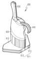
도 1은 본 발명의 1실시예에 따른 내시경 장치(10)를 나타내는 사시도이다. 도 2는 도 1의 내시경 장치(10)의 사용상태도이다.Figure 1 is a perspective view showing an
본 발명의 1실시예에 따른 내시경 장치(10)는 내시경(100)적 용종 절제술(Endoscopic polypectomy)에 폭넓게 사용될 수 있다. 특히 조기 소화기암(식도, 위, 대장)에 대한 내시경(100)적 용종 절제술에 효과적으로 사용될 수 있다.The
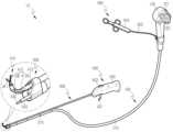
도 1 및 도 2에 도시된 바와 같이, 본 발명의 1실시예에 따른 내시경 장치(10)는 내시경(100), 유연채널(200), 캡(300), 보조팔 모듈(400) 및 소작기(500)를 포함한다.As shown in Figures 1 and 2, the
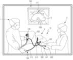
내시경(100)은 상용 내시경으로 구비될 수 있다. 내시경(100)은 삽입부(110) 및 조작부(120)를 포함한다. 도 1에 도시된 바와 같이, 소화기 내과의(1; 이하 '집도의')는 내시경(100)적 용종 절제술을 수행하는 과정에서 삽입부(110) 및 조작부(120)를 조작한다.The
삽입부(110)는 환자(3)의 구강을 통해 인체 내 내강으로 들어가는 부분이다. 내시경(100)적 용종 절제술을 수행하는 과정에서 집도의(1)는 삽입부(110)의 일측을 잡고 환자(3)의 구강을 통해 삽입부(110)를 삽입한다. 집도의(1)는 수술실에 구비된 모니터(700)를 통해 내시경(100)이 환부(4)로 이동했는지 확인할 수 있다.The
삽입부(110)의 길이는 대략 1~5m 정도일 수 있다. 삽입부(110)의 두께는 대략 9.5mm 정도일 수 있다. 삽입부(110)는 내강으로 삽입되며 내강의 굴곡에 따라 유연하게 구부러질 수 있다.The length of the
삽입부(110) 내부에 복수의 케이블과 튜브가 구비된다. 채널(114)은 전기 소작기(500)의 카테터(520)가 이동하는 통로를 형성한다. 케이블은 삽입부(110) 말단의 bending section을 구부리는 장력을 형성한다.A plurality of cables and tubes are provided inside the
삽입부(110) 말단에 대물렌즈(111), 광원렌즈(112), 노즐(113) 및 채널(114)의 말단이 구비된다.The ends of the
삽입부(110) 말단은 조작부(120)와 반대쪽 끝 부분을 의미한다. 내시경(100) 광원의 빛은 광섬유를 통해 내시경(100) 말단의 광원렌즈(112)로 전달된다. 대물렌즈(111)로 입사된 빛은 광섬유와 촬상소자를 거쳐 수술실의 모니터(700)에 출력된다. 노즐(113)은 대물렌즈(111)를 세척하는 액체를 분출한다.The end of the
조작부(120)에 복수의 노브(121; knob), 고정장치(122) 등이 구비된다. 소화기 내과의는 노브(121) 조작을 통해 삽입부(110) 말단의 bending section을 구부릴 수 있다. 소화기 내과의는 고정장치(122) 조작을 통해 노브(121)의 움직임을 차단할 수 있다.The
도 1 및 도 2에 도시된 바와 같이, 유연채널(200)은 긴 튜브 형태를 형성한다. 유연채널(200)은 보조팔(410)이 이동하는 원통형 통로(201)를 형성한다. 유연채널(200)은 의료용 고무, 실리콘 등 탄력적으로 변형하는 재질로 제조될 수 있다. 유연채널(200)은 도구가 들어가는 부분이 리지드(Rigid)한 재질로 이루어질 수도 있다.As shown in Figures 1 and 2, the
유연채널(200)은 그 일부가 삽입부(110)의 길이방향을 따라 통로(201)를 형성하도록 삽입부(110)에 부착된다. 유연채널(200)의 한쪽 끝(선단부)은 캡(300)에 의해 삽입부(110)의 말단 부분(선단부)에 부착된다. 내시경(100)적 용종 절제술을 수행하는 동한 유연채널(200)이 꼬이지 않고 헛돌 수 있도록, 유연채널(200)과 캡(300) 사이에 베어링 또는 부시가 구비될 수 있다.A portion of the
유연채널(200)은 삽입부(110)의 말단으로부터 삽입부(110)의 길이방향을 따라 '일정 길이'만큼 삽입부(110)에 부착된다. 상술한 '일정 길이'는 삽입부(110)가 내강으로 삽입되는 길이보다 긴 길이를 의미한다.The
유연채널(200)은 상술한 '일정 길이' 내에서 복수의 장착부재(210)에 의해 삽입부(110)에 부착된다. 장착부재(210)는 접착테이프(adhesive tape)일 수 있다. 삽입부(110)가 내강에 삽입되면서 내강의 굴곡에 의해 구부러질 때, 유연채널(200)은 장착부재(210)에 의해 삽입부(110)와 함께 구부러지게 된다.The
유연채널(200)은 장착부재(210)에 의해 삽입부(110)에 이동 가능하게 부착될 수 있다. 접착테이프는 유연채널(200)과 점착력을 형성하고, 삽입부(110)와는 점착력을 형성하지 않을 수 있다. 또는, 접착테이프는 삽입부(110)와 점착력을 형성하고, 삽입부(110)와는 점착력을 형성하지 않을 수 있다.The
따라서 삽입부(110)가 내강의 굴곡에 의해 굴곡을 형성하는 과정에서, 유연채널(200)은 삽입부(110)의 밴딩에 대한 저항이 최소화되는 위치로 다소 이동할 수 있다.Therefore, during the process of the
따라서 삽입부(110)가 내강의 굴곡에 의해 밴딩되더라도, 삽입부(110)의 밴딩에 대한 유연채널(200)의 저항이 최소화된다. 또한, 삽입부(110) 말단의 bending section이 반전(retroflection)하도록 밴딩되더라도 bending section의 밴딩에 대한 유연채널(200)의 저항이 감소하게 된다.Therefore, even if the
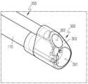
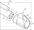
도 3은 도 1의 내시경 장치(10)의 삽입부(110), 유연채널(200) 및 캡(300)을 나타내는 부분확대도이다.FIG. 3 is a partially enlarged view showing the
도 4는 도 3의 삽입부(110), 유연채널(200) 및 캡(300)의 분해사시도이다. 도 5는 도 3의 삽입부(110), 유연채널(200) 및 캡(300)의 정면도이다. 도 6은 도 3의 캡(300)의 측면도이다.FIG. 4 is an exploded perspective view of the
도 3 및 도 4에 도시된 바와 같이, 캡(300)은 유연채널(200)의 선단부를 삽입부(110)의 선단부에 결합한다. 캡(300)에 제1 삽입홀(301) 및 제2 삽입홀(302)이 형성된다.As shown in FIGS. 3 and 4, the
제1 삽입홀(301)에 삽입부(110)의 선단부가 삽입된다. 제1 삽입홀(301)의 지름은 삽입부(110)의 선단부 지름보다 작다. 캡(300)은 의료용 고무, 실리콘 등 탄력적으로 변형하는 재질로 제조된다.The tip of the
따라서, 제1 삽입홀(301)의 내면은 삽입부(110)의 선단부 외면에 밀착된다. 캡(300)은 자체 탄성 회복력에 의해 삽입부(110)의 선단부 외면에 고정될 수 있다. 캡(300)과 삽입부(110)의 결합력을 강화하기 위해, 캡(300)과 삽입부(110) 및 유연채널(200)의 경계를 따라 접착테이프가 테이핑될 수 있다.Accordingly, the inner surface of the
제2 삽입홀(302)에 유연채널(200)의 선단부가 삽입된다. 제2 삽입홀(302)의 지름은 유연채널(200)의 선단부 지름보다 작다. 캡(300)은 의료용 실리콘 등 탄력적으로 변형하는 재질로 제조된다.The tip of the
따라서, 제2 삽입홀(302)의 내면은 유연채널(200)의 선단부 외면에 밀착된다. 캡(300)은 자체 탄성 회복력에 의해 삽입부(110)의 선단부 외면에 고정될 수 있다. 캡(300)과 유연채널(200)의 결합력을 강화하기 위해, 캡(300)과 삽입부(110) 및 유연채널(200)의 경계를 따라 접착테이프가 테이핑될 수 있다.Accordingly, the inner surface of the
캡(300)은 대물렌즈(111)로 입사되는 빛을 차단하지 않도록 투명 재질로 제조된다. 캡(300)의 전면(303)은 삽입부(110)의 선단부보다 앞쪽으로 돌출된다. 따라서 절개 전 환부(4)에 니들을 통한 염색액 주입시, 캡(300)의 전면(303)은 제1 삽입홀(301) 둘레를 따라 환부(4)를 누를 수 있다.The
도 6에 도시된 바와 같이, 캡(300)의 전면(303)은 제1 삽입홀(301)의 중심을 기준으로 제2 삽입홀(302) 쪽으로 갈수록 뒤쪽으로 일정 각도(α) 경사진 형태를 형성한다. 따라서 내시경 장치(10)가 내강의 목적 병변으로 이동하는 과정에서 캡(300)의 전면(303)과 내강 벽의 마찰 발생이 감소하여 내강의 손상 발생이 방지될 수 있다.As shown in FIG. 6, the
도 2에 도시된 바와 같이, 보조팔 모듈(400)은 보조팔(410) 및 조종장치(420)를 포함한다.As shown in FIG. 2, the
조종장치(420)는 보조팔(410)을 조작하는 구성이다. 조종장치(420)에 트리거(421) 및 휠(422; 또는 레버)이 형성된다. 보조의(2)는 집도의(1)의 지시에 따라 조종장치(420)를 조작한다.The
보조팔(410)은 통로(201)에 이동 가능하게 삽입되며, 겸자(411), 밴딩부(412) 및 유연튜브(413)를 포함한다.The
겸자(411)는 인체 조직을 파지하는 구성이다. 겸자(411)는 벌어지고 오므라지는 집게 형태를 형성한다. 트리거(421)와 겸자(411)는 하나 이상의 와이어(미도시)에 의해 연결된다. 보조의(2)가 트리거(421)를 조작하면, 와이어가 당겨지면서 겸자(411)는 벌어지고 오므라지게 된다.The
대한민국 공개특허공보 제2017-0078616호에 개시된 바와 같이 와이어와 겸자(411)의 작동구조는 공지된 기술이므로 이의 자세한 설명은 생략하고자 한다.As disclosed in Korean Patent Publication No. 2017-0078616, the operating structure of the wire and
보조팔(410)은 겸자 이외에도 suction tube, needle, knife, coagulation grasper로 이루어질 수도 있다.In addition to forceps, the
밴딩부(412)는 겸자(411)에 결합된다. 밴딩부(412)는 유연 관절 구조를 형성한다. 밴딩부(412)는 복수의 링크(412A) 및 복수의 텐던(412B)을 포함한다.The bending
링크(412A)들은 겸자(411)로부터 차례대로 배열된다. 텐던(412B)들의 양단은 겸자(411) 및 휠(422)에 연결된다. 텐던(412B)들은 링크(412A)들을 순서대로 관통한다. 조종장치(420)의 휠(422)을 회전시키면, 텐던(412B)들이 선택적으로 당겨지거나 풀리며 밴딩부(412)가 밴딩된다.
대한민국 등록특허공보 제2349030호에 개시된 바와 같이 텐던(412B)과 밴딩부(412)의 작동구조는 공지된 기술이므로 이의 자세한 설명은 생략하고자 한다.As disclosed in Republic of Korea Patent Publication No. 2349030, the operating structure of the
보조팔(410)은 통로(201)에 회전 가능하게 삽입된다. 따라서 보조의(2)가 손목을 돌려서 조종장치(420)를 회전시키면, 보조팔(410)이 통로(201)의 길이방향을 중심으로 회전된다. 따라서 보조의(2)가 조종장치(420)의 회전각을 변화시키면, 보조팔(410)의 다자유도 구동이 가능하게 된다.The
유연튜브(413)는 밴딩부(412)와 조종장치(420)를 연결한다. 유연튜브(413)는 밴딩부(412)와 조종장치(420) 사이에서 와이어 및 텐던(412B)을 수용하는 통로를 형성한다.The
유연튜브(413)는 의료용 고무, 실리콘 등 탄력적으로 변형하는 재질로 제조될 수 있다. 삽입부(110)가 내강에 삽입되면서 내강의 굴곡에 의해 구부러지면, 유연튜브(413)는 유연채널(200) 내에서 유연채널(200)과 함께 구부러지게 된다.The
도 2에 도시된 바와 같이, 소작기(500)는 핸들(510), 카테터(520) 및 와이어(530)를 포함한다. 도시되지는 않았으나, 와이어(530)에 전류를 공급하는 전기 소작기(electro-surgical unit)가 더 구비된다.As shown in Figure 2, the
카테터(520)는 일 방향으로 긴 형태를 형성한다. 카테터(520)는 내부에 중공채널을 형성한다. 카테터(520)는 유연한 재질로 제조된다. 와이어(530)는 중공채널에 삽입된다.The
핸들(510)은 와이어(530)를 조작하는 구성이다. 보조의(2)는 집도의(1)의 지시에 따라 핸들(510)을 조작하여, 와이어(530)를 카테터(520)의 길이 방향을 따라 인입 또는 인출하는 방향으로 제어할 수 있다.The
대한민국 공개특허공보 제2022-0028878호에 개시된 바와 같이 소작기(500)는 공지된 기술이므로 이의 자세한 설명은 생략하고자 한다.As disclosed in Republic of Korea Patent Publication No. 2022-0028878, the
도 7 및 도 8은 도 1의 내시경 장치(10)를 사용한 내시경(100)적 절제술로 제거되고 있는 환부(4)를 나타내는 도면이다.FIGS. 7 and 8 are diagrams showing the affected
집도의(1)가 모니터(700)를 보며 삽입부(110)를 환부(4)로 이동시키면, 보조의(2)가 집도의(1)의 지시에 따라 내시경(100)의 채널(114)에 니들을 삽입하여 환부(4)에 염색액을 주입한다.When the
그리고 나서 보조의(2)는 소작기(500)의 카테터(520)를 내시경(100)의 채널(114)에 삽입한다. 또한, 보조의(2)는 보조팔(410)을 유연채널(200)의 통로(201)에 삽입하여 환부(4)를 향해 겸자(411)와 밴딩부(412)를 돌출시킨다.Then, the
이후 집도의(1)는 모니터(700)를 통해 환부(4)를 관찰하며 삽입부(110), 조작부(120) 및 카테터(520)를 조작하여 환부(4)를 절재한다. 이 과정에서 보조의(2)는 집도의(1)의 지시에 따라 핸들(510)을 조작하여 카테터(520)의 끝단에서 와이어(530)를 입출한다.Afterwards, the
또한, 보조의(2)는 집도의(1)의 지시에 따라 조종장치(420)를 조작하여 겸자(411)로 환부(4)를 파지하고, 밴딩부(412)를 밴딩시켜 환부(4)의 절개가 용이하도록 환부(4)를 당기게 된다.In addition, the assistant surgeon (2) operates the control device (420) according to the instructions of the surgeon (1) to grasp the affected area (4) with the forceps (411) and bends the banding part (412) to control the affected area (4). The affected part (4) is pulled to facilitate incision.
이때, 보조팔(410)은 내시경(100)의 카메라와 독립적으로 움직임으로써, 환부(4)의 시야를 확보한 상태에서 조직의 견인 동작을 효과적으로 수행할 수 있다. 또한, 보조팔(410)은 조종장치(420)를 이용해 조종함으로써 직관적인 조종이 가능한 이점이 있다.At this time, the
본 발명의 1실시예의 내시경 장치의 유효성을 검증하기 위해 살아있는 돼지로 위 ESD를 수행했다(IRB: NOTUS IACUC 20-KE-233,264). 위는 8개 부분으로 구분하였다. 상업용 내시경(GIF Q260J, 일본 올림푸스)을 사용하였으며, 보조팔(410)의 도움이 있는 경우와 없는 경우로 나누어, 위의 각 부분에 위치한 병변까지 ESD를 실시했다.To verify the effectiveness of the endoscopic device of one embodiment of the present invention, gastric ESD was performed on a live pig (IRB: NOTUS IACUC 20-KE-233,264). The stomach was divided into eight parts. A commercial endoscope (GIF Q260J, Olympus, Japan) was used, and ESD was performed on lesions located in each part of the stomach, divided into cases with and without the assistance of the auxiliary arm (410).
ESD는 마킹, 주입, 프리컷, 해부, 시료 인출 순으로 진행되었다. 마킹은 직경 30mm로 실시하였다. 해부하는 동안 보조팔(410)은 점막 조직을 들어올리는 작업을 수행했다. 내시경 수술은 800개 이상의 ESD를 수행한 숙련된 임상의에 의해 수행되었다. 보조팔(410) 제어는 숙련된 엔지니어에 의해 수행되었다.ESD was performed in the following order: marking, injection, precut, dissection, and sample extraction. Marking was performed with a diameter of 30 mm. During dissection, the
총 수술 시간(sec), 프리컷 시간(sec), 해부 속도 (mm2/sec), 천공 횟수 등을 측정하여 효능을 평가하였다. 해부속도는 시료영역을 해부에 소요된 시간으로 나누어 산출하였다.Efficacy was evaluated by measuring total surgery time (sec), precut time (sec), dissection speed (mm2/sec), and number of perforations. Dissection speed was calculated by dividing the sample area by the time required for dissection.
보조팔(410)은 역굴절 자세를 포함한 다양한 내시경 자세에서 잘 휘어지는 것을 확인하였다. 보조팔(410)은 다양한 방향으로 조직 트랙션을 수행할 수 있음을 확인할 수 있었다. 실험 과정에서 보조팔(410)은 조직을 들어올리고 원하는 수준으로 장력을 가할 수 있는 충분한 힘을 발휘하였다. 보조팔(410) 부착으로 인한 위나 식도의 손상도 발견되지 않았다.It was confirmed that the
총 수술 시간, 프리컷 시간, 해부 속도 및 천공 횟수에 대한 결과를 아래 [표 1]에 나타내었다.The results for total surgical time, precut time, dissection speed, and number of punctures are shown in [Table 1] below.
(n=8)Conventional
(n=8)
(n=8)Proposed
(n=8)
time [sec]Total procedure
time [sec]
[sec.]Precut time
[sec.]
speed [mm2/s]Dissection
speed [mm2/s]
보조팔(410) 보조 ESD는 기존 ESD 대비 수술 시간이 단축됨을 확인할 수 있다. 절개 시간은 기존 ESD 대비 다소 길어졌지만 큰 차이는 없었다. 보조팔(410)을 사용했을 때 해부 속도가 1.5배 빨라짐이 확인되었다. 기존 ESD의 경우 1개의 천공이 발생했으나, 보조팔(410) 사용시 천공이 발생하지 않았음을 확인할 수 있다.It can be seen that the surgery time of the auxiliary arm (410) auxiliary ESD is shortened compared to the existing ESD. The incision time was slightly longer than that of the existing ESD, but there was no significant difference. It was confirmed that the dissection speed increased by 1.5 times when the
2실시예Example 2
도 9는 본 발명의 2실시예에 따른 내시경 장치(20)를 나타내는 사시도이다. 도 10은 도 9의 내시경 장치(20)의 조종장치(420), 홀더(600) 및 소작기(500) 핸들(510)의 사용상태를 나타내는 부분사시도이다.Figure 9 is a perspective view showing an
도 9에 도시된 바와 같이, 본 발명의 2실시예에 따른 내시경 장치(20)는 내시경(100), 유연채널(200), 캡(300), 보조팔 모듈(400), 소작기(500) 및 홀더(600)를 포함한다.As shown in Figure 9, the
본 발명의 2실시예에 따른 내시경 장치(20)의 내시경(100), 유연채널(200), 캡(300), 보조팔 모듈(400) 및 소작기(500)는 본 발명의 1실시예와 사실상 동일하다. 따라서 이하에서는 본 발명의 2실시예에 따른 내시경 장치(20)의 용이한 이해를 위해 홀더(600)를 구체적으로 설명하고자 한다.The
도 9 및 도 10에 도시된 바와 같이, 홀더(600)는 양손으로 복수의 수술도구를 운영할 수 있게 하며 유연튜브(413)가 통로(201)에 삽입되는 부분에서 유연채널(200)의 직선 형태를 유지시키는 구성이다. 홀더(600)는 베이스(610), 바디(620), 연장부(630) 및 걸림부(640)를 포함한다.As shown in FIGS. 9 and 10, the
도 11은 도 9의 내시경 장치(20)의 홀더(600)를 나타내는 사시도이다.FIG. 11 is a perspective view showing the
도 11에 도시된 바와 같이, 베이스(610)는 장착홈(611)을 형성하는 구성이다. 장착홈(611)은 유연채널(200)이 삽입되는 직선 형태의 홈으로 이루어진다. 유연채널(200)은 장착홈(611)에 직선 형태로 탈착 결합된다.As shown in FIG. 11, the base 610 forms a mounting
베이스(610)는 홀더(600)의 가장 아래에 구비된다. 홀더(600)의 저면은 평면을 형성한다. 따라서 홀더(600)는 수술 카트 등의 상면에 안착될 수 있다.The
도 10에 도시된 바와 같이, 바디(620)는 사용자 즉, 보조의(2)가 한 손으로 파지하는 구성이다. 바디(620)는 베이스(610) 위에 형성된다. 바디(620)는 베이스(610)로부터 위쪽으로 연장된 형태를 형성한다. 보조의(2)는 바디(620)를 파지하여 장착홈(611)의 위치 및 방향을 조정할 수 있다.As shown in Figure 10, the
유연튜브(413)는 밴딩부(412)와 조종장치(420) 사이에서 와이어 및 텐던(412B)을 수용하는 통로를 형성한다. 유연튜브(413)의 굴곡 발생은 와이어 및 텐던(412B)의 장력에 영향을 미친다. 따라서 내시경(100)적 용종 절제술을 수행하는 과정에서 유연튜브(413)의 형태 유지는 중요하다.The
도 9 및 도 10에 도시된 바와 같이, 내시경(100)적 용종 절제술을 수행하는 동한 유연튜브(413)의 굴곡에 의한 와이어 및 텐던(412B)의 장력 변동을 최소화하려면, 유연튜브(413)를 최대한 직선 형태로 유지시켜야 한다.As shown in Figures 9 and 10, in order to minimize tension fluctuations in the wire and tendon (412B) due to bending of the flexible tube (413) while performing endoscopic polyp resection (100), the flexible tube (413) It should be kept as straight as possible.
도 1을 참조하면, 본 발명의 1실시예에서 보조의(2)는 소작기 핸들(510)을 파지한 손의 약지와 소지로 유연채널(200)을 잡아, 유연튜브(413)가 통로(201)에 삽입되는 부분에서 유연채널(200)의 직선 형태를 유지시켜야 한다.Referring to Figure 1, in one embodiment of the present invention, the auxiliary surgeon (2) holds the
그러나 유연채널(200)이 약지 및 소지와 접촉하는 면적이 작고, 손의 가벼운 떨림에도 유연채널(200)이 약지 및 소지 사이에서 회전되거나 굴곡되기 쉽기 때문에, 소작기 핸들(510)을 조작하고 있는 손의 약지와 소지로 유연채널(200)의 직선 형태를 유지시키는 것은 쉽지 않다.However, since the area where the
도 10에 도시된 바와 같이, 본 발명의 2실시예에서 보조의(2)는 바디(620)를 파지하고 장착홈(611)의 위치 및 방향을 조정함으로써, 유연튜브(413)가 통로(201)에 삽입되는 부분에서 유연채널(200)의 직선 형태를 유지시킬 수 있다.As shown in FIG. 10, in the second embodiment of the present invention, the
도 12는 도 11의 홀더(600)의 장착홈(611)을 나타내는 저면도이다.FIG. 12 is a bottom view showing the mounting
도 12에 도시된 바와 같이, 바디(620)는 기준면(RF)을 기준으로 대칭 형태를 형성한다. 따라서 보조의(2)가 양손 중 어느 하나로 바디(620)를 파지하더라도 기준면(RF)은 보조의(2)의 정면과 대략 동일한 사잇각을 형성하게 된다.As shown in FIG. 12, the
도 11에 도시된 바와 같이, 바디(620)에는 약지 및 소지의 파지 형태에 대응되는 그루브가 형성된다. 보조의(2)는 약지 및 소지 중 하나 이상과 손바닥으로 바디(620)를 파지할 수 있다.As shown in FIG. 11, grooves are formed in the
도 10에 도시된 바와 같이, 보조의(2)는 엄지, 검지 및 중지를 이용 가능한 상태로 바디(620)를 파지할 수 있다. 따라서 보조의(2)는 바디(620)를 파지한 손의 엄지, 검지 및 중지로 소작기 핸들(510)을 쉽게 조작할 수 있다.As shown in FIG. 10, the
도 12에 도시된 바와 같이, 장착홈(611)은 제1 장착홈(612) 및 제2 장착홈(613)을 포함한다.As shown in FIG. 12, the mounting
제1 장착홈(612)은 기준면(RF)과 일정 각도(θ)의 사잇각을 형성한다. 제2 장착홈(613)은 기준면(RF)을 기준으로 제1 장착홈(612)과 대칭 형태를 형성한다. 따라서 제2 장착홈(613)도 기준면(RF)과 θ의 사잇각을 형성한다.The
상술한 일정 각도(θ)의 사잇각은 생체공학적 설계에 의해 도출된다. 사용자가 양손으로 바디(620)와 조종장치(420)를 비교적 편하게 파지한 상태에서 제1 장착홈(612) 또는 제2 장착홈(613)은 조종장치(420)의 전방과 동일선상에 위치할 수 있다. 일 예로, θ는 35°일 수 있다.The included angle of the above-mentioned constant angle (θ) is derived by bionic design. With the user holding the
제1 장착홈(612) 및 제2 장착홈(613)은 유연채널(200)의 지름 이하의 지름을 형성한다. 유연채널(200)은 자체 탄성력에 의해 장착홈(611)과 결합력을 형성할 수 있다.The
도 13은 도 11의 홀더(600)의 장착홈(611)을 나타내는 도면이다.FIG. 13 is a diagram showing the mounting
도 13에 도시된 바와 같이, 유연채널(200)은 제1 장착홈(612) 및 제2 장착홈(613)보다 좁은 진입홈(614)을 통해 제1 장착홈(612) 및 제2 장착홈(613)에 삽입된다. 진입홈(614)의 좁은 틈은 유연채널(200)의 의도치 않은 이탈을 억제한다.As shown in FIG. 13, the
내시경(100)적 용종 절제술을 수행하는 동한 유연채널(200)이 꼬이지 않고 헛돌 수 있도록, 유연채널(200)과 장착홈(611)의 내면 사이에 베어링 또는 부시가 구비될 수 있다.A bearing or bush may be provided between the
도 10 및 도 11에 도시된 바와 같이, 연장부(630)는 바디(620)로부터 위쪽으로 연장된다. 보조의(2)는 손의 엄지와 검지 사이 부분으로 연장부(630)를 감싸줄 수 있다. 따라서 보조의(2)는 약지 및 소지 중 하나 이상과 손바닥으로만 바디(620)를 파지하더라도 바디(620)의 유동을 억제할 수 있다.As shown in FIGS. 10 and 11 , the
걸림부(640)는 바디(620)의 상부로부터 연장된다. 걸림부(640)는 바디(620)를 파지한 약지 및 소지 중 하나 이상의 상부를 감싸는 형태를 형성한다.The locking
바디(620)에 대한 그립력이 해제되더라도, 홀더(600)는 걸림부(640)에 의해 바디(620)를 파지했던 약지 또는 소지에 매달리게 된다. 따라서 보조의(2)의 실수나 외력 등에 의해 바디(620)에 대한 그립력이 해제되더라도 홀더(600)의 낙하 및 이에 따른 의료사고가 방지될 수 있다.Even if the grip force on the
3실시예Example 3
도 14는 신체 부착형 고정장치(700)를 나타내는 도면이다. 도 15는 환자 침대 또는 수술트레이에 고정하는 고정장치(800)를 나타내는 도면이다. 도 16은 상용도구 부착형 고정장치(900)를 나타내는 도면이다.FIG. 14 is a diagram showing a body-attached
도 14 내지 도 16에 도시된 바와 같이, 홀더(600)는 신체 부착형 고정장치(700), 또는 환자침대, 트레이 또는 내시경 도구에 부착되는 (기타) 고정장치(800), 또는 상용도구 부착형 고정장치(900)로 대체될 수 있다.As shown in FIGS. 14 to 16, the
도 14에 도시된 바와 같이, 신체 부착형 고정장치(700)는 보조의(2)의 손목에 고정할 수 있는 장치 또는 환자(3) 신체에 부착할 수 있는 장치를 의미할 수 있다. 신체 부착형 고정장치(700)는 부착베이스(710) 및 부착부재(720; 이하 '제1 부착부재')를 포함할 수 있다. 부착베이스(710)는 2실시예의 베이스(610)와 유사 또는 동일한 구조로 이루어질 수 있다.As shown in FIG. 14, the body-attached
제1 부착부재(720)는 부착베이스(710)에 결합된다. 제1 부착부재(720)는 보조의(2)의 손목 또는 환자(3) 신체에 부착/고정할 수 있는 각종 부재로 이루어진다. 각종 부재는 벨크로 테이프 등 손목 또는 신체에 탈부착 가능한 부재를 의미할 수 있다.The first attachment member 720 is coupled to the attachment base 710. The first attachment member 720 is made of various members that can be attached/fixed to the wrist of the
도 15에 도시된 바와 같이, 기타 고정장치(800)는 이동 트레이형 간이 홀더 또는 시술/수술 침대에 부착 가능한 장치를 의미할 수 있다. 기타 고정장치(800)는 상용 도구의 손잡이 부분에 부착할 수도 있다. 기타 고정장치(800)는 부착베이스(810) 및 부착부재(820; 이하 '제2 부착부재')를 포함할 수 있다. 부착베이스(810)는 2실시예의 베이스(610)와 유사 또는 동일한 구조로 이루어질 수 있다.As shown in FIG. 15, the other fixation device 800 may refer to a movable tray-type simple holder or a device that can be attached to a procedure/surgical bed. Other fixing devices 800 can also be attached to the handle of a commercial tool. Other fixing devices 800 may include an attachment base 810 and an attachment member 820 (hereinafter referred to as 'second attachment member'). The attachment base 810 may have a similar or identical structure to the
제2 부착부재(820)는 부착베이스(810)에 결합된다. 제2 부착부재(820)는 이동 트레이형 간이 홀더 또는 시술/수술 침대에 부착 가능한 각종 부재로 이루어진다. 각종 부재는 클램프, 집게, 벨크로 테이프 등 이동 트레이형 간이 홀더 또는 시술/수술 침대에 탈부착 가능한 부재를 의미할 수 있다.The second attachment member 820 is coupled to the attachment base 810. The second attachment member 820 is made of a simple movable tray-type holder or various members attachable to a treatment/surgical bed. Various members may refer to simple mobile tray-type holders such as clamps, forceps, and Velcro tapes, or members that are attachable and detachable to the procedure/surgical bed.
도 15에 도시된 바와 같이, 상용도구 부착형 고정장치(900)는 글자그대로 상용도구에 부착 가능한 장치를 의미할 수 있다. 상용도구 부착형 고정장치(900)는 부착베이스(910) 및 부착부재(920; 이하 '제3 부착부재')를 포함할 수 있다. 부착베이스(910)는 2실시예의 베이스(610)와 유사 또는 동일한 구조로 이루어질 수 있다.As shown in FIG. 15, the commercial tool attachment fixing device 900 may literally mean a device that can be attached to a commercial tool. The commercial tool attachment type fixture 900 may include an attachment base 910 and an attachment member 920 (hereinafter referred to as a 'third attachment member'). The attachment base 910 may have a similar or identical structure to the
제3 부착부재(920)는 부착베이스(910)에 결합된다. 제3 부착부재(920)는 부착베이스(910) 위에 형성된다. 제3 부착부재(920)는 보조의(2)가 한 손으로 파지하는 구성이다. 제3 부착부재(920)는 2실시예의 바디(620)와 유사 또는 동일한 구조로 이루어질 수 있다.The third attachment member 920 is coupled to the attachment base 910. The third attachment member 920 is formed on the attachment base 910. The third attachment member 920 is configured to be held by the
제3 부착부재(920)는 부착베이스(910)로부터 위쪽으로 연장된 형태를 형성한다. 제3 부착부재(920)는 상용도구에 부착될 수 있다. 여기서, 상용도구는 전기 소작기(500A)를 의미할 수 있다. 이때, 제3 부착부재(920)는 전기 소작기(500A)의 핸들(510A)에 부착될 수 있다. 일 예로, 제3 부착부재(920)의 상부에 핸들(510A)이 끼워지는 홈이 형성될 수 있다. 보조의(2)는 바디(620)를 파지한 상태에서 핸들(510A)을 조작하여, 와이어(530)를 카테터(520A)의 길이 방향을 따라 인입 또는 인출하는 방향으로 제어할 수 있다.The third attachment member 920 extends upward from the attachment base 910. The third attachment member 920 may be attached to a commercial tool. Here, the commercial tool may mean an electric cautery (500A). At this time, the third attachment member 920 may be attached to the handle 510A of the electric cautery 500A. For example, a groove into which the handle 510A is inserted may be formed in the upper part of the third attachment member 920. The
도 17은 캡(300)의 변형상태를 나타내는 측면도이다. 도 18은 캡(300)의 형상이 복원된 상태를 나타내는 측면도이다. 도 19는 보조팔(410)이 캡(300)의 앞쪽으로 인출된 상태를 나타내는 측면도이다.Figure 17 is a side view showing the deformed state of the
도 17에 도시된 바와 같이, 캡(300)은 장기 내부 점막에 접촉할 때 납작해질 수 있는 유연재질로 이루어질 수 있다. 일 예로, 캡(300)은 의료용 고무, 실리콘 등 탄력적으로 변형하는 재질로 제조될 수 있다. 도 17의 화살표는 장기 내부 점막이 캡(300)에 작용하는 힘을 의미한다. 캡(300)은 장기 내부 점막에 접촉할 때 납작해짐으로써, 식도 및 대장에 직경이 큰 내시경 도구를 삽입할 때 발생할 수 있는 점막의 긁힘현상을 최소화할 수 있다.As shown in FIG. 17, the
도 18 및 도 19에 도시된 바와 같이, 캡(300)은 보조팔(410)이 통로에서 전진할 때 보조팔(410)에 의해 형태가 원상으로 복구될 수 있다. 보조팔(410)이 전진할 시, 유연 채널(200)과 캡(300)이 원상으로 복구되어 보조팔(410)이 원활히 전진할 수 있도록 채널(200) 및 캡(300)의 내부를 윤활제 도포 및 코팅할 수 있다.As shown in FIGS. 18 and 19, the
도 20 내지 도 22는 도 1의 내시경 장치(10)를 사용한 내시경적 절제술로 제거되고 있는 환부(4)를 나타내는 도면이다.20 to 22 are diagrams showing the affected
도 20에 도시된 바와 같이, 겸자(411)는 벌어지고 오므라지는 집게 형태를 형성한다. 그러나 환부(4)의 점막 조직이 수평으로 누워있는 경우, 겸자(411)가 점막 조직을 잡기 어려울 수 있다.As shown in Figure 20, the
도 21에 도시된 바와 같이, 겸자(411)가 납작한 조직을 잡기 용이하도록, 겸자(411)와 밴딩부(412)는 서로 결합되는 부분에서 평행하지 않을 수 있다. 따라서, 밴딩부(412)가 환부를 향해 구부러지 상태에서, 겸자(411)는 환부(4)의 점막 조직을 향할 수 있다. 따라서, 환부(4)의 점막 조직이 수평으로 누워있는 경우, 겸자(411)가 점막 조직을 용이하게 잡을 수 있다.As shown in FIG. 21, so that the
도 22에 도시된 바와 같이, 겸자(411)가 납작한 조직을 잡기 용이하도록, 집게 형태의 어느 한쪽은 다른 한쪽보다 긴 형태를 형성할 수 있다. 즉, 겸자(411)의 하단 턱이 상단 턱보다 길 경우, 납작한 조직의 파지가 용이해질 수 있다.As shown in FIG. 22, one side of the
본 발명에 의하면, 겸자(411)가 파지한 인체 조직이 당겨지도록 밴딩부(412)가 조종장치(420)에 의해 밴딩됨에 따라, 내시경(100)이 정지한 상태에서 보조팔(410)의 견인 방향 및 파지 위치 조정이 가능하도록 이루어지는 내시경 장치(10)를 제공할 수 있게 된다.According to the present invention, as the bending
또한, 보조팔(410)이 유연 관절 구조를 형성하여 전후, 상하, 좌우로 자유로운 움직임을 구현함으로써, 보조팔(410)의 다자유도 구동이 가능하여 조직 절제시 시야 확보 및 조직의 견인동작을 효과적으로 수행 가능하도록 이루어지는 내시경 장치(10)를 제공할 수 있게 된다.In addition, the
또한, 캡(300)의 전단면은 제1 삽입홀(301)의 중심을 기준으로 제2 삽입홀(302) 쪽으로 갈수록 뒤쪽으로 경사짐으로써, 내시경(100)이 목적 병변으로 삽입되는 과정에서 내강의 상처 발생이 차단되도록 이루어지는 내시경 장치(10)를 제공할 수 있게 된다.In addition, the front surface of the
또한, 유연튜브(413)가 통로(201)에 삽입되는 부분에 구비된 홀더(600)가 유연채널(200)의 직선 형태를 유지시킴으로써, 보조의(2)가 양손으로 내시경(100) 수술기구 및 조종장치(420)를 동시에 파지한 상태에서, 유연튜브(413)의 형태 변형이 차단되도록 이루어지는 내시경 장치(20)를 제공할 수 있게 된다.In addition, the
앞에서, 본 발명의 특정한 실시예가 설명되고 도시되었지만 본 발명은 기재된 실시예에 한정되는 것이 아니고, 본 발명의 사상 및 범위를 벗어나지 않고 다양하게 수정 및 변형할 수 있음은 이 기술의 분야에서 통상의 지식을 가진 자에게 자명한 일이다. 따라서, 그러한 수정예 또는 변형예들은 본 발명의 기술적 사상이나 관점으로부터 개별적으로 이해되어서는 안되며, 변형된 실시예들은 본 발명의 특허청구범위에 속한다 하여야 할 것이다.Although specific embodiments of the present invention have been described and shown above, it is known in the art that the present invention is not limited to the described embodiments, and that various modifications and changes can be made without departing from the spirit and scope of the present invention. This is self-evident to those who have it. Accordingly, such modifications or variations should not be understood individually from the technical idea or viewpoint of the present invention, and the modified embodiments should be regarded as falling within the scope of the claims of the present invention.
10,20 : 내시경 장치
100 : 내시경200 : 유연채널
110 : 삽입부201 : 통로
111 : 대물렌즈210 : 장착부재
112 : 광원렌즈300 : 캡
113 : 노즐301 : 제1 삽입홀
114 : 채널302 : 제2 삽입홀
120 : 조작부303 : 전면
121 : 노브600 : 홀더
122 : 고정장치610 : 베이스
400 : 보조 로봇팔 모듈611 : 장착홈
410 : 보조 로봇팔612 : 제1 장착홈
411 : 겸자613 : 제2 장착홈
412 : 밴딩부614 : 진입홈
412A : 링크620 : 바디
412B : 텐던RF : 기준면
413 : 유연튜브630 : 연장부
420 : 조종장치640 : 걸림부
421 : 트리거700 : 모니터
422 : 휠1 : 집도의
500 : 소작기2 : 보조의
510 : 핸들3 : 환자
520 : 카테터4 : 환부
530 : 와이어10,20: Endoscopic device
100: Endoscope 200: Flexible channel
110: insertion part 201: passage
111: objective lens 210: mounting member
112: light source lens 300: cap
113: nozzle 301: first insertion hole
114: Channel 302: Second insertion hole
120: control panel 303: front
121: Knob 600: Holder
122: Fixing device 610: Base
400: Auxiliary robot arm module 611: Mounting groove
410: Auxiliary robot arm 612: First mounting groove
411: Forceps 613: Second mounting groove
412: Banding part 614: Entry groove
412A: Link 620: Body
412B: Tendon RF: Reference plane
413: Flexible tube 630: Extension part
420: Control device 640: Locking part
421: Trigger 700: Monitor
422: Wheel 1: Surgeon
500: cautery 2: auxiliary
510: Handle 3: Patient
520: Catheter 4: Affected area
530: wire
Claims (21)
Translated fromKorean일부가 상기 삽입부의 길이방향을 따라 통로를 형성하도록 상기 삽입부에 부착되는 유연채널; 및
상기 통로에 이동 가능하게 삽입되고, 조종장치에 의해 조작되는 보조팔을 포함하고,
상기 보조팔은,
인체 조직을 파지 가능한 겸자; 및
상기 겸자가 파지한 인체 조직이 당겨지도록 상기 조종장치에 의해 밴딩되는 밴딩부를 포함하는 것을 특징으로 하는 내시경 장치.An endoscope having a flexible insertion section for insertion into the human body;
a flexible channel partially attached to the insertion portion to form a passage along the longitudinal direction of the insertion portion; and
It includes an auxiliary arm movably inserted into the passage and operated by a control device,
The auxiliary arm is,
Forceps capable of grasping human tissue; and
An endoscope device comprising a bending portion that is bent by the manipulation device to pull the human tissue gripped by the forceps.
상기 밴딩부는 유연 관절 구조를 형성하는 것을 특징으로 하는 내시경 장치.According to paragraph 1,
An endoscopic device, wherein the bending portion forms a flexible joint structure.
상기 밴딩부는,
복수의 링크;
상기 겸자에 결합되고, 상기 링크들을 순서대로 관통하는 복수의 텐던을 포함하는 것을 특징으로 하는 내시경 장치.According to paragraph 2,
The banding part,
plural links;
An endoscopic device coupled to the forceps and comprising a plurality of tendons sequentially passing through the links.
상기 보조팔의 다자유도 구동이 가능하도록, 상기 보조팔은 상기 통로에 회전 가능하게 삽입되는 것을 특징으로 하는 내시경 장치.According to paragraph 1,
An endoscope device, wherein the auxiliary arm is rotatably inserted into the passage so as to enable operation of the auxiliary arm in multiple degrees of freedom.
상기 유연채널의 선단부를 상기 삽입부의 선단부에 결합하는 캡을 포함하는 것을 특징으로 하는 내시경 장치.According to paragraph 1,
An endoscope device comprising a cap that couples the tip of the flexible channel to the tip of the insertion unit.
상기 캡에는,
상기 삽입부의 선단부가 삽입되는 제1 삽입홀; 및
상기 유연채널의 선단부가 삽입되는 제2 삽입홀이 형성되는 것을 특징으로 하는 내시경 장치.According to clause 5,
In the cap,
a first insertion hole into which the tip of the insertion portion is inserted; and
An endoscope device, characterized in that a second insertion hole is formed into which the tip of the flexible channel is inserted.
상기 캡의 전면은 상기 제1 삽입홀의 중심을 기준으로 상기 제2 삽입홀 쪽으로 갈수록 뒤쪽으로 경사진 것을 특징으로 하는 내시경 장치.According to clause 6,
The endoscope device is characterized in that the front of the cap is inclined backward toward the second insertion hole based on the center of the first insertion hole.
상기 보조팔은 상기 밴딩부와 상기 조종장치를 연결하는 유연튜브를 포함하는 것을 특징으로 하는 내시경 장치.According to paragraph 1,
The auxiliary arm is an endoscope device characterized in that it includes a flexible tube connecting the bending portion and the control device.
상기 유연튜브가 상기 통로에 삽입되는 부분에서 상기 유연채널의 직선 형태를 유지시키는 홀더를 포함하는 것을 특징으로 하는 내시경 장치.According to clause 8,
An endoscope device comprising a holder that maintains the straight shape of the flexible channel at a portion where the flexible tube is inserted into the passage.
상기 홀더는,
상기 유연채널이 삽입되는 직선 형태의 장착홈을 형성하는 베이스; 및
상기 베이스 위에 형성되고, 상기 장착홈의 위치 및 방향이 조정되도록 사용자가 파지하는 바디를 포함하는 것을 특징으로 하는 내시경 장치.According to clause 8,
The holder is,
A base forming a straight mounting groove into which the flexible channel is inserted; and
An endoscope device comprising a body formed on the base and held by a user to adjust the position and direction of the mounting groove.
상기 바디는 양손 중 어느 하나로 파지하도록 기준면을 기준으로 대칭 형태를 형성하고,
상기 장착홈은,
상기 기준면과 사잇각을 형성하는 제1 장착홈; 및
상기 기준면을 기준으로 제1 장착홈과 대칭 형태를 형성하는 제2 장착홈을 포함하는 것을 특징으로 하는 내시경 장치.According to clause 10,
The body forms a symmetrical shape with respect to the reference plane so that it can be gripped with either hand,
The mounting groove is,
a first mounting groove forming an angle between the reference surface and the reference surface; and
An endoscope device comprising a first mounting groove and a second mounting groove forming a symmetrical shape with respect to the reference plane.
상기 홀더는,
상기 유연채널이 직선 형태로 탈착 결합되는 베이스; 및
상기 베이스 위에 형성되고, 사용자가 파지하는 바디를 포함하는 것을 특징으로 하는 내시경 장치.According to clause 8,
The holder is,
A base to which the flexible channel is detachably coupled in a straight line; and
An endoscope device comprising a body formed on the base and held by a user.
상기 홀더는,
사용자가 엄지와 검지 사이로 감싸도록 상기 바디로부터 위쪽으로 연장되는 연장부를 포함하는 것을 특징으로 하는 내시경 장치.According to clause 12,
The holder is,
An endoscopic device comprising an extension extending upward from the body so that a user wraps it between his or her thumb and index finger.
상기 홀더는 상기 바디로부터 연장되는 걸림부를 포함하고,
상기 바디에 대한 그립력이 해제될 경우, 상기 홀더는 상기 걸림부에 의해 상기 바디를 파지했던 약지 또는 소지에 매달리는 것을 특징으로 하는 내시경 장치.According to clause 12,
The holder includes a locking portion extending from the body,
When the grip force on the body is released, the holder hangs on the ring finger or small finger that held the body by the locking portion.
상기 유연튜브가 상기 통로에 삽입되는 부분에서 상기 유연채널의 직선 형태를 유지시키는 신체 부착형 고정장치를 포함하는 것을 특징으로 하는 내시경 장치.According to clause 8,
An endoscope device comprising a body-attached fixation device that maintains a straight shape of the flexible channel at a portion where the flexible tube is inserted into the passage.
상기 신체 부착형 고정장치는,
상기 유연채널이 직선 형태로 탈착 결합되는 부착베이스; 및
상기 부착베이스에 결합되고, 보조의의 손목에 고정 또는 환자 신체에 부착 가능한 부착부재를 포함하는 것을 특징으로 하는 내시경 장치.According to clause 15,
The body-attached fixation device,
An attachment base to which the flexible channel is detachably coupled in a straight line; and
An endoscopic device coupled to the attachment base and comprising an attachment member that can be fixed to the wrist of an assistant surgeon or attached to the patient's body.
상기 유연튜브가 상기 통로에 삽입되는 부분에서 상기 유연채널의 직선 형태를 유지시키는 고정장치를 포함하는 것을 특징으로 하는 내시경 장치.According to clause 8,
An endoscope device comprising a fixing device that maintains a straight shape of the flexible channel at a portion where the flexible tube is inserted into the passage.
상기 고정장치는,
상기 유연채널이 직선 형태로 탈착 결합되는 부착베이스; 및
상기 부착베이스에 결합되고, 이동 트레이형 간이 홀더 또는 수술 침대에 부착 가능한 부착부재를 포함하는 것을 특징으로 하는 내시경 장치.According to clause 15,
The fixture is,
An attachment base to which the flexible channel is detachably coupled in a straight line; and
An endoscopic device coupled to the attachment base and comprising an attachment member attachable to a simple holder in the form of a mobile tray or a surgical bed.
상기 캡은 장기 내부 점막에 접촉할 때 납작해질 수 있는 유연재질로 이루어지고, 상기 보조팔이 상기 통로에서 전진할 때 상기 보조팔에 의해 형태가 원상복구되는 것을 특징으로 하는 내시경 장치.According to clause 6,
The cap is made of a flexible material that can be flattened when in contact with the internal mucosa of the organ, and its shape is restored by the auxiliary arm when the auxiliary arm advances in the passage.
상기 겸자는 벌어지고 오므라지는 집게 형태를 형성하고,
상기 겸자가 납작한 조직을 잡기 용이하도록, 상기 집게 형태의 어느 한쪽은 다른 한쪽보다 긴 것을 특징으로 하는 내시경 장치.According to paragraph 1,
The forceps form a forceps shape that opens and retracts,
An endoscopic device, wherein one side of the forceps shape is longer than the other side so that the forceps can easily grasp flat tissue.
상기 밴딩부는 상기 겸자에 결합되고,
상기 겸자가 납작한 조직을 잡기 용이하도록, 상기 겸자와 상기 밴딩부는 서로 결합되는 부분에서 평행하지 않은 것을 특징으로 하는 내시경 장치.According to paragraph 1,
The bending portion is coupled to the forceps,
An endoscopic device, wherein the forceps and the bending portion are not parallel at the point where they are joined to each other so that the forceps can easily grasp flat tissue.
Priority Applications (4)
| Application Number | Priority Date | Filing Date | Title |
|---|---|---|---|
| KR1020220115232AKR20240036408A (en) | 2022-09-13 | 2022-09-13 | Endoscope apparatus |
| EP22208521.9AEP4338654A1 (en) | 2022-09-13 | 2022-11-21 | Endoscope apparatus |
| US17/991,296US20240081850A1 (en) | 2022-09-13 | 2022-11-21 | Endoscope apparatus |
| CN202211476313.5ACN117694814A (en) | 2022-09-13 | 2022-11-23 | Endoscopic equipment |
Applications Claiming Priority (1)
| Application Number | Priority Date | Filing Date | Title |
|---|---|---|---|
| KR1020220115232AKR20240036408A (en) | 2022-09-13 | 2022-09-13 | Endoscope apparatus |
Publications (1)
| Publication Number | Publication Date |
|---|---|
| KR20240036408Atrue KR20240036408A (en) | 2024-03-20 |
Family
ID=84360508
Family Applications (1)
| Application Number | Title | Priority Date | Filing Date |
|---|---|---|---|
| KR1020220115232ACeasedKR20240036408A (en) | 2022-09-13 | 2022-09-13 | Endoscope apparatus |
Country Status (4)
| Country | Link |
|---|---|
| US (1) | US20240081850A1 (en) |
| EP (1) | EP4338654A1 (en) |
| KR (1) | KR20240036408A (en) |
| CN (1) | CN117694814A (en) |
Families Citing this family (3)
| Publication number | Priority date | Publication date | Assignee | Title |
|---|---|---|---|---|
| CN118319395B (en)* | 2024-06-13 | 2024-08-30 | 安徽医科大学第一附属医院 | Endoscope structure for surgical operation |
| CN118975827B (en)* | 2024-08-20 | 2025-05-27 | 中国人民解放军总医院第一医学中心 | Channel catheter auxiliary large wound surface suturing system for single-forceps endoscope |
| CN119423672B (en)* | 2024-11-05 | 2025-09-09 | 浙江大学 | Controllable transparent cap for auxiliary digestive endoscope controlled by brushless motor and method |
Citations (1)
| Publication number | Priority date | Publication date | Assignee | Title |
|---|---|---|---|---|
| JP2005131211A (en) | 2003-10-31 | 2005-05-26 | Olympus Corp | Externally mounted channel for endoscope |
Family Cites Families (7)
| Publication number | Priority date | Publication date | Assignee | Title |
|---|---|---|---|---|
| JP4980777B2 (en)* | 2007-04-06 | 2012-07-18 | オリンパスメディカルシステムズ株式会社 | Endoscopic treatment tool |
| SG176213A1 (en)* | 2009-05-29 | 2011-12-29 | Univ Nanyang Tech | Robotic system for flexible endoscopy |
| JP6214464B2 (en)* | 2014-05-15 | 2017-10-18 | オリンパス株式会社 | Endoscope system |
| BR112017007856A2 (en) | 2014-10-29 | 2017-12-26 | Sumitomo Bakelite Co | endoscopic scissors and high frequency endoscopic treatment tool |
| KR102349030B1 (en) | 2019-08-29 | 2022-01-10 | 한국과학기술원 | Flexible drive manipulator |
| KR102452158B1 (en) | 2020-08-31 | 2022-10-11 | 연세대학교 산학협력단 | Catheter for endoscope |
| EP4228493A4 (en)* | 2020-10-13 | 2025-02-19 | Theragi LLC | Systems and methods for endoscopic surgery |
- 2022
- 2022-09-13KRKR1020220115232Apatent/KR20240036408A/ennot_activeCeased
- 2022-11-21USUS17/991,296patent/US20240081850A1/enactivePending
- 2022-11-21EPEP22208521.9Apatent/EP4338654A1/enactivePending
- 2022-11-23CNCN202211476313.5Apatent/CN117694814A/enactivePending
Patent Citations (1)
| Publication number | Priority date | Publication date | Assignee | Title |
|---|---|---|---|---|
| JP2005131211A (en) | 2003-10-31 | 2005-05-26 | Olympus Corp | Externally mounted channel for endoscope |
Also Published As
| Publication number | Publication date |
|---|---|
| CN117694814A (en) | 2024-03-15 |
| US20240081850A1 (en) | 2024-03-14 |
| EP4338654A1 (en) | 2024-03-20 |
Similar Documents
| Publication | Publication Date | Title |
|---|---|---|
| JP7138214B2 (en) | Treatment tool, endoscope device and endoscope system | |
| US11395579B2 (en) | Portable endoscope with disposable steerable cannula | |
| US8444547B2 (en) | Medical treatment endoscope | |
| JP3163274B2 (en) | Endoscopic surgical instrument | |
| JP5009251B2 (en) | Arthroscopic instruments | |
| KR20240036408A (en) | Endoscope apparatus | |
| JP3679674B2 (en) | Endoscope | |
| JP2022126757A (en) | scope system | |
| JP2000037348A (en) | Endoscope for treatment | |
| JP6099829B2 (en) | Auxiliary tool and endoscope system | |
| CN114096187B (en) | Portable endoscope with disposable steerable cannula | |
| WO2019202699A1 (en) | Medical device | |
| US10136798B2 (en) | Endoscopic system | |
| WO2018079044A1 (en) | Endoscope fixing means | |
| JP4499965B2 (en) | Endoscope device | |
| JP4514864B2 (en) | Endoscope | |
| US20210015348A1 (en) | Endoscopic tool stabilization and related methods of use | |
| JP4276832B2 (en) | Endoscope device | |
| US20220354515A1 (en) | Endoscopic side snare tools and methods for use | |
| CN210582627U (en) | Treatment tool for endoscope |
Legal Events
| Date | Code | Title | Description |
|---|---|---|---|
| PA0109 | Patent application | St.27 status event code:A-0-1-A10-A12-nap-PA0109 | |
| PA0201 | Request for examination | St.27 status event code:A-1-2-D10-D11-exm-PA0201 | |
| R18-X000 | Changes to party contact information recorded | St.27 status event code:A-3-3-R10-R18-oth-X000 | |
| PG1501 | Laying open of application | St.27 status event code:A-1-1-Q10-Q12-nap-PG1501 | |
| R17-X000 | Change to representative recorded | St.27 status event code:A-3-3-R10-R17-oth-X000 | |
| D13-X000 | Search requested | St.27 status event code:A-1-2-D10-D13-srh-X000 | |
| D14-X000 | Search report completed | St.27 status event code:A-1-2-D10-D14-srh-X000 | |
| E902 | Notification of reason for refusal | ||
| PE0902 | Notice of grounds for rejection | St.27 status event code:A-1-2-D10-D21-exm-PE0902 | |
| E13-X000 | Pre-grant limitation requested | St.27 status event code:A-2-3-E10-E13-lim-X000 | |
| P11-X000 | Amendment of application requested | St.27 status event code:A-2-2-P10-P11-nap-X000 | |
| P13-X000 | Application amended | St.27 status event code:A-2-2-P10-P13-nap-X000 | |
| E601 | Decision to refuse application | ||
| PE0601 | Decision on rejection of patent | St.27 status event code:N-2-6-B10-B15-exm-PE0601 | |
| E13-X000 | Pre-grant limitation requested | St.27 status event code:A-2-3-E10-E13-lim-X000 | |
| P11-X000 | Amendment of application requested | St.27 status event code:A-2-2-P10-P11-nap-X000 | |
| R18-X000 | Changes to party contact information recorded | St.27 status event code:A-3-3-R10-R18-oth-X000 | |
| PE0902 | Notice of grounds for rejection | St.27 status event code:A-1-2-D10-D21-exm-PE0902 | |
| E13-X000 | Pre-grant limitation requested | St.27 status event code:A-2-3-E10-E13-lim-X000 | |
| P11-X000 | Amendment of application requested | St.27 status event code:A-2-2-P10-P11-nap-X000 |