KR20240022042A - Electric Moxibustion System Using Low-frequency Electrical Stimulation - Google Patents
Electric Moxibustion System Using Low-frequency Electrical StimulationDownload PDFInfo
- Publication number
- KR20240022042A KR20240022042AKR1020220100094AKR20220100094AKR20240022042AKR 20240022042 AKR20240022042 AKR 20240022042AKR 1020220100094 AKR1020220100094 AKR 1020220100094AKR 20220100094 AKR20220100094 AKR 20220100094AKR 20240022042 AKR20240022042 AKR 20240022042A
- Authority
- KR
- South Korea
- Prior art keywords
- low
- electrode pad
- housing
- control unit
- electric
- Prior art date
- Legal status (The legal status is an assumption and is not a legal conclusion. Google has not performed a legal analysis and makes no representation as to the accuracy of the status listed.)
- Pending
Links
- 230000000638stimulationEffects0.000titleclaimsdescription50
- 238000010438heat treatmentMethods0.000claimsabstractdescription49
- 238000005485electric heatingMethods0.000claimsabstractdescription21
- 239000002131composite materialSubstances0.000claimsdescription21
- 238000000034methodMethods0.000claimsdescription7
- 239000007769metal materialSubstances0.000claimsdescription4
- 238000001467acupunctureMethods0.000abstractdescription24
- 230000009471actionEffects0.000abstractdescription3
- XLYOFNOQVPJJNP-UHFFFAOYSA-NwaterSubstancesOXLYOFNOQVPJJNP-UHFFFAOYSA-N0.000description16
- 230000000694effectsEffects0.000description10
- 238000010586diagramMethods0.000description7
- 230000006870functionEffects0.000description7
- 239000000047productSubstances0.000description4
- 238000002485combustion reactionMethods0.000description3
- 239000003814drugSubstances0.000description3
- 230000006872improvementEffects0.000description3
- 239000000463materialSubstances0.000description3
- 210000003205muscleAnatomy0.000description3
- 229940124595oriental medicineDrugs0.000description3
- 230000009467reductionEffects0.000description3
- 238000011160researchMethods0.000description3
- 238000010792warmingMethods0.000description3
- 208000023178Musculoskeletal diseaseDiseases0.000description2
- 230000008901benefitEffects0.000description2
- 230000017531blood circulationEffects0.000description2
- 230000008859changeEffects0.000description2
- 239000003086colorantSubstances0.000description2
- 238000011161developmentMethods0.000description2
- 238000012986modificationMethods0.000description2
- 230000004048modificationEffects0.000description2
- 210000005036nerveAnatomy0.000description2
- 230000008569processEffects0.000description2
- 230000004044responseEffects0.000description2
- 238000002560therapeutic procedureMethods0.000description2
- 240000006891Artemisia vulgarisSpecies0.000description1
- 235000003261Artemisia vulgarisNutrition0.000description1
- RYGMFSIKBFXOCR-UHFFFAOYSA-NCopperChemical compound[Cu]RYGMFSIKBFXOCR-UHFFFAOYSA-N0.000description1
- 230000003213activating effectEffects0.000description1
- 230000004913activationEffects0.000description1
- 238000007792additionMethods0.000description1
- 230000003321amplificationEffects0.000description1
- 239000006227byproductSubstances0.000description1
- 238000006243chemical reactionMethods0.000description1
- 229910052802copperInorganic materials0.000description1
- 239000010949copperSubstances0.000description1
- 201000010099diseaseDiseases0.000description1
- 208000037265diseases, disorders, signs and symptomsDiseases0.000description1
- 238000010291electrical methodMethods0.000description1
- 238000005516engineering processMethods0.000description1
- 230000020169heat generationEffects0.000description1
- 238000002847impedance measurementMethods0.000description1
- 208000017445musculoskeletal system diseaseDiseases0.000description1
- 238000003199nucleic acid amplification methodMethods0.000description1
- 238000013021overheatingMethods0.000description1
- 238000000554physical therapyMethods0.000description1
- 238000012827research and developmentMethods0.000description1
- 239000011347resinSubstances0.000description1
- 229920005989resinPolymers0.000description1
- 239000000779smokeSubstances0.000description1
- 230000004936stimulating effectEffects0.000description1
- 238000006467substitution reactionMethods0.000description1
- 238000002604ultrasonographyMethods0.000description1
Images


Classifications
- A—HUMAN NECESSITIES
- A61—MEDICAL OR VETERINARY SCIENCE; HYGIENE
- A61H—PHYSICAL THERAPY APPARATUS, e.g. DEVICES FOR LOCATING OR STIMULATING REFLEX POINTS IN THE BODY; ARTIFICIAL RESPIRATION; MASSAGE; BATHING DEVICES FOR SPECIAL THERAPEUTIC OR HYGIENIC PURPOSES OR SPECIFIC PARTS OF THE BODY
- A61H39/00—Devices for locating or stimulating specific reflex points of the body for physical therapy, e.g. acupuncture
- A61H39/06—Devices for heating or cooling such points within cell-life limits
- A—HUMAN NECESSITIES
- A61—MEDICAL OR VETERINARY SCIENCE; HYGIENE
- A61H—PHYSICAL THERAPY APPARATUS, e.g. DEVICES FOR LOCATING OR STIMULATING REFLEX POINTS IN THE BODY; ARTIFICIAL RESPIRATION; MASSAGE; BATHING DEVICES FOR SPECIAL THERAPEUTIC OR HYGIENIC PURPOSES OR SPECIFIC PARTS OF THE BODY
- A61H23/00—Percussion or vibration massage, e.g. using supersonic vibration; Suction-vibration massage; Massage with moving diaphragms
- A61H23/02—Percussion or vibration massage, e.g. using supersonic vibration; Suction-vibration massage; Massage with moving diaphragms with electric or magnetic drive
- A61H23/0218—Percussion or vibration massage, e.g. using supersonic vibration; Suction-vibration massage; Massage with moving diaphragms with electric or magnetic drive with alternating magnetic fields producing a translating or oscillating movement
- A61H23/0236—Percussion or vibration massage, e.g. using supersonic vibration; Suction-vibration massage; Massage with moving diaphragms with electric or magnetic drive with alternating magnetic fields producing a translating or oscillating movement using sonic waves, e.g. using loudspeakers
- A—HUMAN NECESSITIES
- A61—MEDICAL OR VETERINARY SCIENCE; HYGIENE
- A61H—PHYSICAL THERAPY APPARATUS, e.g. DEVICES FOR LOCATING OR STIMULATING REFLEX POINTS IN THE BODY; ARTIFICIAL RESPIRATION; MASSAGE; BATHING DEVICES FOR SPECIAL THERAPEUTIC OR HYGIENIC PURPOSES OR SPECIFIC PARTS OF THE BODY
- A61H39/00—Devices for locating or stimulating specific reflex points of the body for physical therapy, e.g. acupuncture
- A61H39/002—Using electric currents
- A—HUMAN NECESSITIES
- A61—MEDICAL OR VETERINARY SCIENCE; HYGIENE
- A61H—PHYSICAL THERAPY APPARATUS, e.g. DEVICES FOR LOCATING OR STIMULATING REFLEX POINTS IN THE BODY; ARTIFICIAL RESPIRATION; MASSAGE; BATHING DEVICES FOR SPECIAL THERAPEUTIC OR HYGIENIC PURPOSES OR SPECIFIC PARTS OF THE BODY
- A61H39/00—Devices for locating or stimulating specific reflex points of the body for physical therapy, e.g. acupuncture
- A61H39/007—Stimulation by mechanical vibrations, e.g. ultrasonic
- A—HUMAN NECESSITIES
- A61—MEDICAL OR VETERINARY SCIENCE; HYGIENE
- A61N—ELECTROTHERAPY; MAGNETOTHERAPY; RADIATION THERAPY; ULTRASOUND THERAPY
- A61N1/00—Electrotherapy; Circuits therefor
- A61N1/02—Details
- A61N1/04—Electrodes
- A61N1/0404—Electrodes for external use
- A61N1/0408—Use-related aspects
- A61N1/0452—Specially adapted for transcutaneous muscle stimulation [TMS]
- A—HUMAN NECESSITIES
- A61—MEDICAL OR VETERINARY SCIENCE; HYGIENE
- A61N—ELECTROTHERAPY; MAGNETOTHERAPY; RADIATION THERAPY; ULTRASOUND THERAPY
- A61N1/00—Electrotherapy; Circuits therefor
- A61N1/02—Details
- A61N1/04—Electrodes
- A61N1/0404—Electrodes for external use
- A61N1/0472—Structure-related aspects
- A61N1/0492—Patch electrodes
- A—HUMAN NECESSITIES
- A61—MEDICAL OR VETERINARY SCIENCE; HYGIENE
- A61N—ELECTROTHERAPY; MAGNETOTHERAPY; RADIATION THERAPY; ULTRASOUND THERAPY
- A61N1/00—Electrotherapy; Circuits therefor
- A61N1/18—Applying electric currents by contact electrodes
- A61N1/32—Applying electric currents by contact electrodes alternating or intermittent currents
- A61N1/36—Applying electric currents by contact electrodes alternating or intermittent currents for stimulation
- A61N1/36014—External stimulators, e.g. with patch electrodes
- A61N1/3603—Control systems
- A—HUMAN NECESSITIES
- A61—MEDICAL OR VETERINARY SCIENCE; HYGIENE
- A61H—PHYSICAL THERAPY APPARATUS, e.g. DEVICES FOR LOCATING OR STIMULATING REFLEX POINTS IN THE BODY; ARTIFICIAL RESPIRATION; MASSAGE; BATHING DEVICES FOR SPECIAL THERAPEUTIC OR HYGIENIC PURPOSES OR SPECIFIC PARTS OF THE BODY
- A61H39/00—Devices for locating or stimulating specific reflex points of the body for physical therapy, e.g. acupuncture
- A61H2039/005—Devices for locating or stimulating specific reflex points of the body for physical therapy, e.g. acupuncture by means of electromagnetic waves, e.g. I.R., U.V. rays
- A—HUMAN NECESSITIES
- A61—MEDICAL OR VETERINARY SCIENCE; HYGIENE
- A61H—PHYSICAL THERAPY APPARATUS, e.g. DEVICES FOR LOCATING OR STIMULATING REFLEX POINTS IN THE BODY; ARTIFICIAL RESPIRATION; MASSAGE; BATHING DEVICES FOR SPECIAL THERAPEUTIC OR HYGIENIC PURPOSES OR SPECIFIC PARTS OF THE BODY
- A61H2201/00—Characteristics of apparatus not provided for in the preceding codes
- A61H2201/02—Characteristics of apparatus not provided for in the preceding codes heated or cooled
- A61H2201/0207—Characteristics of apparatus not provided for in the preceding codes heated or cooled heated
- A—HUMAN NECESSITIES
- A61—MEDICAL OR VETERINARY SCIENCE; HYGIENE
- A61H—PHYSICAL THERAPY APPARATUS, e.g. DEVICES FOR LOCATING OR STIMULATING REFLEX POINTS IN THE BODY; ARTIFICIAL RESPIRATION; MASSAGE; BATHING DEVICES FOR SPECIAL THERAPEUTIC OR HYGIENIC PURPOSES OR SPECIFIC PARTS OF THE BODY
- A61H2201/00—Characteristics of apparatus not provided for in the preceding codes
- A61H2201/02—Characteristics of apparatus not provided for in the preceding codes heated or cooled
- A61H2201/0221—Mechanism for heating or cooling
- A61H2201/0228—Mechanism for heating or cooling heated by an electric resistance element
- A—HUMAN NECESSITIES
- A61—MEDICAL OR VETERINARY SCIENCE; HYGIENE
- A61H—PHYSICAL THERAPY APPARATUS, e.g. DEVICES FOR LOCATING OR STIMULATING REFLEX POINTS IN THE BODY; ARTIFICIAL RESPIRATION; MASSAGE; BATHING DEVICES FOR SPECIAL THERAPEUTIC OR HYGIENIC PURPOSES OR SPECIFIC PARTS OF THE BODY
- A61H2201/00—Characteristics of apparatus not provided for in the preceding codes
- A61H2201/10—Characteristics of apparatus not provided for in the preceding codes with further special therapeutic means, e.g. electrotherapy, magneto therapy or radiation therapy, chromo therapy, infrared or ultraviolet therapy
- A—HUMAN NECESSITIES
- A61—MEDICAL OR VETERINARY SCIENCE; HYGIENE
- A61H—PHYSICAL THERAPY APPARATUS, e.g. DEVICES FOR LOCATING OR STIMULATING REFLEX POINTS IN THE BODY; ARTIFICIAL RESPIRATION; MASSAGE; BATHING DEVICES FOR SPECIAL THERAPEUTIC OR HYGIENIC PURPOSES OR SPECIFIC PARTS OF THE BODY
- A61H2201/00—Characteristics of apparatus not provided for in the preceding codes
- A61H2201/50—Control means thereof
- A61H2201/5058—Sensors or detectors
- A61H2201/5082—Temperature sensors
Landscapes
- Health & Medical Sciences (AREA)
- Life Sciences & Earth Sciences (AREA)
- Public Health (AREA)
- Veterinary Medicine (AREA)
- Animal Behavior & Ethology (AREA)
- General Health & Medical Sciences (AREA)
- Rehabilitation Therapy (AREA)
- Engineering & Computer Science (AREA)
- Physical Education & Sports Medicine (AREA)
- Pain & Pain Management (AREA)
- Epidemiology (AREA)
- Biomedical Technology (AREA)
- Nuclear Medicine, Radiotherapy & Molecular Imaging (AREA)
- Radiology & Medical Imaging (AREA)
- Biophysics (AREA)
- Heart & Thoracic Surgery (AREA)
- Mechanical Engineering (AREA)
- Electrotherapy Devices (AREA)
Abstract
Description
Translated fromKorean본 발명은 전기식 온구기에 관한 것으로, 더욱 상세하게는 히터와 저주파 전기자극 전극패드를 경혈에 접촉시켜 온열 작용과 저주파 전기자극 작용을 동시에 인가하여 효과적인 뜸 치료가 가능하게 구성한 저주파 전기 자극 전기식 온구기 및 이를 갖는 전기식 온구기 시스템에 관한 것이다.The present invention relates to an electric warming device, and more specifically, to a low-frequency electrical stimulation electric warming device configured to enable effective moxibustion treatment by simultaneously applying thermal action and low-frequency electrical stimulation by bringing a heater and a low-frequency electrical stimulation electrode pad into contact with acupuncture points. and an electric water heater system having the same.
한방에서 치료 방법으로 널리 사용 중인 침구(鍼灸)요법은 동양의학에서 가장 높은 평가를 받는 요법이다. 그 중 뜸 치료는 대표적으로 쑥에 불을 붙여 발생하는 열을 경혈에 인가하여 발생하는 생체반응을 통해 다양한 병증을 치료하는 방법이다. 현재는 연소체를 사용하지 않고 전기적 방법을 활용하여 발생하는 열을 이용 및 제어하여 기존에 사용하는 연소체에서 발생하는 온도를 동일하게 재연하여 경혈에 열을 인가함으로써 연소체를 사용하였을 때와 같은 효과를 낼 수 있는 제품에 대한 연구 개발에 사용되고 있다.Acupuncture therapy, which is widely used as a treatment method in Oriental medicine, is the most highly regarded therapy in Oriental medicine. Among them, moxibustion treatment is a method of treating various diseases through biological reactions that occur by applying heat generated by lighting mugwort to the acupuncture points. Currently, instead of using a combustion body, the heat generated by using an electrical method is used and controlled to reproduce the same temperature generated by the existing combustion body and apply heat to the acupuncture points, making it the same as when using a combustion body. It is being used in research and development for products that can be effective.
전기식 온구기는 발생하는 열을 제어하여 경혈에 인가하는 방식과 고주파 펄스를 이용하여 심부에 열을 인가하는 방식을 통해 정량적으로 경혈에 인가 할 수 있는 방식이 있다. 이것은 연기, 부산물, 화상 등이 발생하지 않고 사용의 편의성을 제공하는 장점을 가지고 있다.There are two types of electric heating devices: a method that controls the heat generated and applies it to the acupuncture points, and a method that can apply heat to the acupuncture points quantitatively by using high-frequency pulses to apply heat to the deep area. This has the advantage of providing convenience of use without generating smoke, by-products, or burns.
전기식 온구기 및 고주파 펄스 온열기에 대한 연구들은 경혈의 열적 자극에 관한 내용에 편중되어 대체의학으로 한방 의료기기에 관한 관심이 증대하고 있는 시점에서 다양한 제품 요구를 맞추지 못하고 있는 실정이다. 따라서 온열과 동시에 경혈을 자극할 수 있는, 즉 뜸과 침을 동시에 시술할 수 있는 제품의 개발과 그에 대한 연구가 필요하다. 저주파 전기자극의 경우 다양한 의료분야에서 활용하고 있으며 대표적으로 재활의학 및 물리치료 분야에서 많이 활용되고 있다. 침과 유사하게 하나의 포인트에 에너지를 집중할 수 있는 저주파 전기 자극, 저출력 레이저, 초음파 등과 같이 양방에서 다양한 의료분야에 치료에 활용되고 있는 검증된 기술들을 한방에도 적용하여 활용할 필요성이 제기되고 있다.Research on electric warmers and high-frequency pulse warmers has been focused on thermal stimulation of acupuncture points, and is failing to meet diverse product demands at a time when interest in oriental medical devices as alternative medicine is increasing. Therefore, the development and research of products that can stimulate acupuncture points while providing heat, that is, can perform moxibustion and acupuncture at the same time, are needed. Low-frequency electrical stimulation is used in various medical fields, and is most commonly used in the fields of rehabilitation medicine and physical therapy. Similar to acupuncture, there is a need to utilize proven technologies that are used in various medical fields in Western medicine, such as low-frequency electrical stimulation, low-power laser, and ultrasound, which can focus energy on a single point, by applying them to Oriental medicine.
그동안 저주파 전기자극기와 전기식 온구기에 대하여 개별 연구는 많이 진행되었으나 두 가지의 기능을 결합한 제품의 개발은 미미한 실정이다.Although much individual research has been conducted on low-frequency electric stimulators and electric heating devices, the development of products that combine the functions of the two is minimal.
본 발명의 목적은 히터와 EMS 전극패드를 경혈에 접촉시켜 온열 작용과 저주파 전기자극 작용을 동시에 인가함으로써 효과적인 뜸 치료가 가능하며, 사용이 편리한 저주파 전기 자극 전기식 온구기 및 이를 갖는 전기식 온구기 시스템를 제공하는 것이다.The purpose of the present invention is to provide an easy-to-use low-frequency electrical stimulation electric warmer and an electric warmer system having the same, which enable effective moxibustion treatment by simultaneously applying heating and low-frequency electrical stimulation by contacting the heater and EMS electrode pad to acupuncture points. It is done.
상기한 목적을 달성하기 위한 본 발명의 한 형태에 따른 저주파 전기 자극 전기식 온구기는, 하우징; 상기 하우징의 하부면 중심부에 설치되어 발열하는 온열부; 상기 하우징의 하부면 주변부에 설치되어 저주파 전기 자극을 가하는 EMS 전극패드; 및, 상기 하우징의 내부 공간에 설치되어 상기 온열부 및 EMS 전극패드에 전기신호를 인가하여 제어하는 제어부;를 포함할 수 있다.A low-frequency electrical stimulation electric heating device according to one form of the present invention for achieving the above object includes a housing; a heating unit installed at the center of the lower surface of the housing to generate heat; EMS electrode pads installed around the lower surface of the housing to apply low-frequency electrical stimulation; And, a control unit installed in the inner space of the housing to control the heating unit and the EMS electrode pad by applying an electric signal.
상기 EMS 전극패드는 2개가 상기 온열부의 양측에 일정한 간격을 두고 배치될 수 있다.Two EMS electrode pads may be arranged at regular intervals on both sides of the heating unit.
상기 온열부는 열전도성 금속 재질로 되어 피부와 접촉하는 히터패드와, 상기 히터패드에 설치되며 상기 제어부와 전기적으로 연결되어 발열하는 발열 트랜지스터와, 상기 히터패드의 온도를 감지하여 제어부로 전송하는 온도센서를 포함할 수 있다.The heating unit includes a heater pad made of a thermally conductive metal material and in contact with the skin, a heating transistor installed on the heater pad and electrically connected to the control unit to generate heat, and a temperature sensor that detects the temperature of the heater pad and transmits it to the control unit. may include.
상기 히터패드와 EMS 전극패드는 제어부와 전기적으로 연결되는 인쇄회로기판(PCB)에 함께 설치되어 동시에 피부에 접촉할 수 있다.The heater pad and the EMS electrode pad are installed together on a printed circuit board (PCB) electrically connected to the control unit and can simultaneously contact the skin.
상기 제어부는 상기 EMS 전극패드가 외부의 전원공급장치의 충전단자와 접속될 때 전원을 충전하는 충전지를 포함할 수 있다.The control unit may include a rechargeable battery that charges power when the EMS electrode pad is connected to a charging terminal of an external power supply.
본 발명의 전기식 온구기는, 상기 하우징 내부에 설치되어 상기 제어부로부터 인가되는 전기신호에 의해 음성 대역(20㎐ ~ 200㎑)의 파형으로 진동하면서 인체에 음파진동을 가하는 음파진동자를 더 포함할 수 있다.The electric heating device of the present invention is installed inside the housing and vibrates in a waveform in the audio band (20 Hz to 200 kHz) by an electric signal applied from the control unit, and may further include a sonic vibrator that applies sonic vibration to the human body. there is.
본 발명의 다른 한 형태에 따른 저주파 전기 자극 전기식 온구기는, 하우징; 상기 하우징의 하부면 중심부에 설치되어 제어부에서 인가되는 전기신호에 의해 발열하거나 저주파 전기 자극을 가하는 복합 전극패드; 원형으로 되어 상기 하우징의 하부면에서 상기 복합 전극패드의 외측을 둘러싸도록 설치되어 제어부에서 인가되는 전기신호에 의해 상기 복합 전극패드와 연동하여 저주파 전기 자극을 가하는 EMS 전극패드; 및, 상기 하우징의 내부 공간에 설치되어 상기 복합 전극패드 및 EMS 전극패드에 전기신호를 인가하여 제어하는 제어부;를 포함할 수 있다.A low-frequency electrical stimulation electric heating device according to another aspect of the present invention includes a housing; A composite electrode pad installed at the center of the lower surface of the housing to generate heat or apply low-frequency electrical stimulation by an electrical signal applied from a control unit; an EMS electrode pad that is circular and installed to surround the outside of the composite electrode pad on the lower surface of the housing and applies low-frequency electrical stimulation in conjunction with the composite electrode pad by an electrical signal applied from a control unit; And, a control unit installed in the inner space of the housing to control the composite electrode pad and the EMS electrode pad by applying an electric signal.
상기 제어부는 상기 복합 전극패드 및 EMS 전극패드가 외부의 전원공급장치의 충전단자와 접속될 때 전원을 충전하는 충전지를 포함할 수 있다.The control unit may include a rechargeable battery that charges power when the composite electrode pad and the EMS electrode pad are connected to a charging terminal of an external power supply.
이 경우에도 본 발명의 전기식 온구기는, 상기 하우징 내부에 설치되어 상기 제어부로부터 인가되는 전기신호에 의해 음성 대역(20㎐ ~ 200㎑)의 파형으로 진동하면서 인체에 음파진동을 가하는 음파진동자를 더 포함할 수 있다.In this case as well, the electric heater of the present invention further includes a sonic vibrator that is installed inside the housing and applies sonic vibration to the human body while vibrating in a waveform in the audio band (20 Hz to 200 kHz) by an electric signal applied from the control unit. It can be included.
본 발명에 따른 전기식 온구기 시스템은, 함체 형태로 된 본체부; 상기 본체부의 내부에 설치되는 전원공급장치; 상기 전원공급장치와 전기적으로 연결되고 상기 본체부의 상부면에 돌출되게 형성되는 복수의 충전단자를 구비한 온구기 장착부; 및, 상기 온구기 장착부에 장착되면서 상기 충전단자와 전기적으로 연결되어 충전이 이루어지는 저주파 전기 자극 전기식 온구기;를 포함할 수 있다.The electric heating system according to the present invention includes a main body in the form of a box; A power supply device installed inside the main body; A heating device mounting unit electrically connected to the power supply device and having a plurality of charging terminals protruding from the upper surface of the main body unit; And, a low-frequency electric stimulation electric heater that is mounted on the heater mounting unit and electrically connected to the charging terminal to be charged.
상기 전기식 온구기 시스템의 전기식 온구기는 전극패드가 충전단자와 접촉하여 전원공급장치와 전기적으로 연결될 수 있다.The electric heater of the electric heater system may be electrically connected to the power supply device by having an electrode pad in contact with a charging terminal.
본 발명에 따르면, 온열부와 EMS 전극패드가 신체의 경혈 부위와 인접한 피부에 밀착된 상태에서 온열부를 통해 온열이 가해짐과 동시에 EMS 전극패드를 저주파가 발생하게 되므로 온열부의 열이 경혈 부위의 심부까지 침투하여 치료 효과를 향상시킬 수 있고, 저주파 전기 자극을 좁은 경혈점에 집중하여 경혈의 심부를 자극함으로써 뜸의 효능과 함께 침의 효능도 함께 얻을 수 있는 효과가 있다.According to the present invention, when the heating unit and the EMS electrode pad are in close contact with the skin adjacent to the acupuncture point area of the body, heat is applied through the heating unit and at the same time low frequency is generated in the EMS electrode pad, so that the heat from the heating unit is distributed to the deep part of the acupuncture point area. It can penetrate to improve the treatment effect, and by concentrating low-frequency electrical stimulation on a narrow acupuncture point to stimulate the deep part of the acupuncture point, it has the effect of obtaining the efficacy of acupuncture along with the efficacy of moxibustion.
또한 대략 20㎐ ~ 200㎑ 의 가청 주파수 대역의 파형으로 진동하는 음파진동자가 내장되는 경우, 음파진동자의 진동에 의해 제공되는 음향 파동이 인체에 음향 공명을 발생시켜 부드러운 음파가 인체 내부까지 깊숙히 침투할 수 있도록 하고, 이를 통해 통증감소, 혈액순환개선, 신경피드백 활성화, 근골격 질환 개선, 재활, 스트레스 감소 수면개선 등의 효과도 얻을 수 있다.In addition, when a sound wave vibrator that vibrates in a waveform of the audible frequency band of approximately 20 Hz to 200 kHz is built in, the sound waves provided by the vibration of the sound wave vibrator create acoustic resonance in the human body, allowing soft sound waves to penetrate deep into the human body. Through this, effects such as pain reduction, blood circulation improvement, nerve feedback activation, musculoskeletal disease improvement, rehabilitation, stress reduction, and sleep improvement can be achieved.
도 1은 본 발명의 일 실시예에 따른 전기식 온구기 시스템을 나타낸 사시도이다.
도 2는 도 1에 도시한 전기식 온구기 시스템의 요부 단면도이다.
도 3은 본 발명의 일 실시예에 따른 전기식 온구기를 나타낸 사시도이다.
도 4는 도 3에 도시한 전기식 온구기의 하부에서 본 저면 사시도이다.
도 5는 도 3에 도시한 전기식 온구기의 작용원리를 설명하는 도면이다.
도 6은 본 발명의 일 실시예에 따른 전기식 온구기의 제어를 위한 구성을 나타낸 도면이다.
도 7은 본 발명의 일 실시예에 따른 전기식 온구기의 온도제어 알고리즘을 나타낸 순서도이다.
도 8은 본 발명의 일 실시예에 따른 전기식 온구기의 온도 제어 프로그램의 예를 나타낸 그래프이다.
도 9는 본 발명의 일 실시예에 따른 전기식 온구기의 저주파 전기 자극의 제어를 위한 구성을 나타낸 도면이다.
도 10은 본 발명의 일 실시예에 따른 전기식 온구기의 저주파 전기 자극을 위한 회로 구성을 나타낸 도면이다.
도 11은 본 발명의 일 실시예에 따른 전기식 온구기의 저주파 전기 자극을 위한 Duty Cycle에 따른 저주파전기자극 출력 전압을 나타낸 그래프이다.
도 12는 본 발명의 일 실시예에 따른 전기식 온구기의 저주파 전기 자극 제어알고리즘을 설명하는 순서도이다.
도 13은 본 발명의 다른 실시예에 따른 전기식 온구기를 나타낸 사시도이다.
도 14는 도 13에 도시한 전기식 온구기의 작용원리를 설명하는 도면이다.
도 15는 본 발명의 다른 실시예에 따른 전기식 온구기의 구성도이다.
도 16은 도 15에 도시한 전기식 온구기의 작용원리를 설명하는 도면이다.
도 17은 도 15에 도시한 전기식 온구기의 제어프로세스를 설명하는 순서도이다.Figure 1 is a perspective view showing an electric water heater system according to an embodiment of the present invention.
FIG. 2 is a cross-sectional view of the main part of the electric heater system shown in FIG. 1.
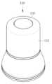
Figure 3 is a perspective view showing an electric water heater according to an embodiment of the present invention.
Figure 4 is a bottom perspective view seen from the bottom of the electric heater shown in Figure 3.
Figure 5 is a diagram explaining the operating principle of the electric water heater shown in Figure 3.
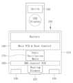
Figure 6 is a diagram showing a configuration for controlling an electric water heater according to an embodiment of the present invention.
Figure 7 is a flowchart showing the temperature control algorithm of an electric water heater according to an embodiment of the present invention.
Figure 8 is a graph showing an example of a temperature control program of an electric water heater according to an embodiment of the present invention.
Figure 9 is a diagram showing a configuration for controlling low-frequency electrical stimulation of an electric water heater according to an embodiment of the present invention.
Figure 10 is a diagram showing a circuit configuration for low-frequency electrical stimulation of an electric water heater according to an embodiment of the present invention.
Figure 11 is a graph showing the low-frequency electrical stimulation output voltage according to Duty Cycle for low-frequency electrical stimulation of an electric water heater according to an embodiment of the present invention.
Figure 12 is a flowchart explaining a low-frequency electrical stimulation control algorithm of an electric water heater according to an embodiment of the present invention.
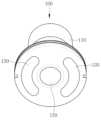
Figure 13 is a perspective view showing an electric water heater according to another embodiment of the present invention.
FIG. 14 is a diagram explaining the operating principle of the electric water heater shown in FIG. 13.
Figure 15 is a configuration diagram of an electric water heater according to another embodiment of the present invention.
FIG. 16 is a diagram explaining the operating principle of the electric water heater shown in FIG. 15.
FIG. 17 is a flowchart explaining the control process of the electric heater shown in FIG. 15.
본 명세서에 기재된 실시예와 도면에 도시된 구성은 개시된 발명의 바람직한 일 예에 불과할 뿐이며, 본 출원의 출원시점에 있어서 본 명세서의 실시예와 도면을 대체할 수 있는 다양한 변형 예들이 있을 수 있다.The embodiments described in this specification and the configurations shown in the drawings are only preferred examples of the disclosed invention, and at the time of filing this application, there may be various modifications that can replace the embodiments and drawings in this specification.
이하에서는 첨부된 도면을 참조하여 저주파 전기 자극 전기식 온구기 및 이를 갖는 전기식 온구기 시스템을 후술된 실시예들에 따라 구체적으로 설명하도록 한다. 도면에서 동일한 부호는 동일한 구성 요소를 나타낸다.Hereinafter, with reference to the attached drawings, a low-frequency electrical stimulation electric heater and an electric heater system having the same will be described in detail according to the embodiments described below. In the drawings, like symbols represent like components.
도 1 및 도 2를 참조하면, 본 발명의 일 실시예에 따른 전기식 온구기 시스템(1)은 함체 형태로 된 본체부(10), 본체부(10)의 상부를 개폐하는 덮개부(15), 본체부(10)의 내부에 설치되는 전원공급장치(30), 전원공급장치(30)와 전기적으로 연결되고 본체부(10)의 상부면에 돌출되게 형성되는 복수의 충전단자(25)를 구비한 온구기 장착부(20), 상기 온구기 장착부(20)에 장착되는 전기식 온구기(100)를 포함한다.Referring to Figures 1 and 2, the electric heater system (1) according to an embodiment of the present invention includes a main body part (10) in the form of a box, and a cover part (15) that opens and closes the upper part of the main body part (10). , a
본체부(10)는 대략 직사각형의 함체 형태로 이루어질 수 있으며, 상부면에 복수의 온구기 장착부(20)가 복수의 열로 배열될 수 있다. 본체부(10)의 상부는 덮개부(15)에 의해 개폐될 수 있다. 덮개부(15)는 본체부(10)의 상부에 장착되는 전기식 온구기(100) 및 그 충전 상태를 볼 수 있도록 투명하거나 반투명한 재질로 이루어질 수 있지만, 이에 한정하지는 않는다. 또한 덮개부(15)는 일단이 본체부의 상단부 일측 가장자리에 힌지어셈블리(미도시)를 매개로 회전이 가능하게 연결되어 덮개부(15)가 본체부(10)에 대해 회전하면서 본체부(10)의 상부를 개폐할 수 있다.The
온구기 장착부(20)는 전기식 온구기(100)의 하부 형태와 대응하는 홈 형태를 가질 수 있다. 각각의 온구기 장착부(20)에는 전기식 온구기(100) 내에 탑재된 충전지(미도시)를 충전하기 위한 2개씩의 충전단자(25)가 상측으로 돌출되게 형성될 수 있다. 각각의 충전단자(25)는 전기식 온구기(100)의 하부면으로 노출된 전극패드와 접촉하면서 전원공급장치(30)와 전기식 온구기(100)를 전기적으로 연결한다.The heating
그리고, 각각의 온구기 장착부(20)의 테두리 부분에는 전기식 온구기(100)의 충전 상태를 외부의 사용자가 육안으로 인식할 수 있도록 빛을 방출하는 발광부(40)가 설치될 수 있다. 발광부(40)는 광투과성 수지 재질의 커버링(41) 내측에 본체부(10) 내의 전원공급장치(30)와 전기적으로 연결되어 발광하는 LED와 같은 램프(42)를 포함할 수 있다. 램프(42)는 충전 상태에 따라 각각 다른 색상의 빛을 방출하도록 서로 다른 색상의 빛을 방출하는 복수의 LED로 구성될 수 있다. 또한 도면에 도시하지는 않았지만, 본체부(10)에는 스피커가 설치되어 충전 상태 또는 사용 상태를 외부의 사용자에게 음성이나 음향으로 전달할 수도 있을 것이다.In addition, a
전원공급장치(30)는 본체부(10)의 내부에 설치되며, 충전단자(25) 및 발광부(40)의 램프(42)와 전기적으로 연결되어, 충전단자(25)를 통해 전기식 온구기(100)에 전원을 공급하여 충전을 함과 더불어, 램프(42)를 통해 충전 상태를 육안으로 인식할 수 있도록 하는 작용을 한다. 전원공급장치(30)는 복수의 전기식 온구기(100)에 전원을 공급하여 충전을 할 수 있도록 배터리(32)와, 배터리(32)의 전원을 충전단자(25) 및 램프(42)로 인가하는 전원공급회로부(31)를 포함할 수 있다.The
도 2 내지 도 6에 도시한 것과 같이, 전기식 온구기(100)는 하우징(110)과, 하우징(110)의 하부면 중심부에 설치되어 발열하는 온열부(120)와, 하우징(110)의 하부면 주변부에 설치되어 저주파 전기 자극을 가하는 2개의 EMS 전극패드(130), 및 하우징(110)의 내부 공간에 설치되어 온열부(120) 및 EMS 전극패드(130)에 전기신호를 인가하여 작동을 제어하는 제어부(140)를 포함할 수 있다.As shown in FIGS. 2 to 6, the
하우징(110)은 통 형태로 되어 그 하단부가 전기식 온구기 시스템(1)의 본체부(10)에 마련된 온구기 장착부(20) 내측으로 삽입될 수 있으며, 사용자가 한 손으로 잡고 사용하기 용이한 크기와 형태로 이루어진다. 이 실시예에서 하우징(110)은 하부는 콘(cone) 형태이고 상부는 직경이 일정한 원기둥 형태를 갖지만 이에 한정하지는 않는다.The
하우징(110)의 하부면에는 온열부(120)의 히터패드(121)와 EMS 전극패드(130)가 외부로 노출될 수 있도록 복수의 개구부가 마련될 수 있다. 그리고 하우징(110)의 상부면에는 제어부(140)와 전기적으로 연결된 전원스위치(150)가 마련될 수 있다. 전원스위치(150) 자체 또는 전원스위치(150)의 일측에는 전원스위치(150)의 온/오프 상태를 표시하는 LED(미도시)가 마련될 수 있다.A plurality of openings may be provided on the lower surface of the
EMS 전극패드(130)는 전기 전도성이 우수한 구리와 같은 재질로 이루어지며, 대략 원호형태로 되어 2개가 온열부(120)의 양측에 일정한 간격(이 실시예에서 180°)을 두고 배치될 수 있다.The
온열부(120)는 열전도성 금속 재질로 되어 피부와 접촉하는 원반형의 히터패드(121)와, 상기 히터패드(121)에 설치되며 제어부(140)와 전기적으로 연결되어 발열하는 발열 트랜지스터(122)와, 상기 히터패드(121)의 온도를 감지하여 제어부(140)로 전송하는 온도센서(123)를 포함할 수 있다.The
상기 히터패드(121)와 2개의 EMS 전극패드(130)는 제어부(140)와 전기적으로 연결되는 인쇄회로기판(PCB)(160)에 함께 설치되며, 하우징(110) 하부면의 개구부를 통해 외부로 노출되어 동시에 피부에 접촉할 수 있다.The
제어부(140)는 온열부(120)의 발열 트랜지스터(122)와 EMS 전극패드(130)에 전기 신호를 각각 인가하여 발열 트랜지스터(122)의 발열과 EMS 전극패드(130)의 저주파 전기 자극을 제어한다. 도 6에 도시한 것과 같이 제어부(140)는 예를 들어 EMS 전극패드(130)의 저주파 전기 자극의 제어에 필요한 MCU, 저주파 전기 자극 출력 전압을 조절하는 엔코더(Encoder), 전압 레벨 및 온열부(120) 동작을 표시하는 LED Display, Voltage boost, 저주파 전기 자극 출력부(LFES)를 포함할 수 있다.The
또한 제어부(140)는 EMS 전극패드(130)가 전기식 온구기 시스템(1)의 충전단자(25)와 접속될 때 전원을 충전하는 충전지(142)를 포함할 수 있다.Additionally, the
제어부(140)는 온열부(120)의 온도센서(123)로부터 피드백되는 온도를 값을 이용하여 PWM의 듀티사이클(Duty Cycle) 제어로 발열 트랜지스터(122)에 인가되는 전류를 제어함으로써 온열부(120)가 특정 온도까지의 상승 및 유지 할 수 있도록 하는 기능을 한다.The
제어부(140)에 의한 온열부(120)의 온도제어 알고리즘은 도 7과 같으며, 시작과 동시에 타이머가 동작하고 실시간으로 피드백되는 ΔT(℃)로 목표 온도까지 상승과 유지를 하고 동작 시간이 끝남에 따라 종료되도록 설계될 수 있다. 도 8은 제어부(140)의 온도제어 알고리즘을 통해 프로그램된 온열부(120)의 온도이다. 제어 이상으로 과열 시 화상의 우려가 있으므로 설정된 온도 이상 변화량이 감지되면 종료되는 것이 바람직하다.The temperature control algorithm of the
EMS 전극패드(130)는 제어부(140)로부터 전기 신호를 인가받아 저주파를 발생시킨다. EMS 전극패드(130)에 의한 저주파 전기 자극은 전압의 변화를 이용하여 심부의 근육을 자극하는 것으로, 높은 전압을 얻기 위하여 제어부(140)는 Voltage Boost 원리 즉, 코일의 역기전력을 이용하여 입력전압보다 높은 전압을 얻을 수 있게 구성된다. 이 때 발생하는 역기전력의 전압 V= L × di/dt 이다. 도 9에 도시한 것과 같이 역기전력을 만들기 위해 코일에 연결된 트랜지스터를 PWM으로 ON/OFF 함으로써 원하는 전압을 조절할 수 있도록 구성하고, 도 10에 도시한 것과 같이 회로를 구성할 수 있다. VCC를 L1(파워인덕터), 트랜지스터, PWM으로 전압 증폭을 통해 저주파 전기자극 전압을 제어한다.The
PWM Duty Cycle에 따른 전압 변화는 도 11과 같으며, 전압의 강도에 따른 근육의 반응은 개인별로 상이하므로 Duty Cycle 을 조절할 수 있도록 로터리엔코더의 펄스를 이용하여 3.3V~90V 까지 조절할 수 있도록 구성할 수 있다.The voltage change according to the PWM Duty Cycle is shown in Figure 11. Since the muscle response according to the intensity of voltage is different for each individual, the duty cycle can be configured to be adjusted from 3.3V to 90V using the pulse of the rotary encoder. You can.
제어부(140)의 EMS 전극패드(130) 제어 알고리즘은 도 12에 도시한 것과 같이, 시작과 동시에 인체 임피던스 측정을 통해 피부접촉 여부를 확인한 후 저주파 전기 자극과 타이머가 동작하며 동작 시간 이내에서 로터리엔코더를 사용하여 전압을 조절할 수 있다.As shown in FIG. 12, the
이러한 구성으로 이루어진 전기식 온구기(100)는 다음과 같이 작동할 수 있다.The
전기식 온구기(100)를 사용하기 위해 전기식 온구기 시스템의 덮개부(15)를 열고, 본체부(10) 상부면에 장착된 복수의 전기식 온구기(100) 중 충전이 완료된 전기식 온구기(100)를 온구기 장착부(20)에서 분리한다.To use the
그리고 한 손으로 하우징(110)을 잡고, 하우징(110)의 하부면을 사용자의 신체 부위(예를 들어 경혈 부위)에 밀착시켜 온열부(120)의 히터패드(121)와 EMS 전극패드(130)를 피부에 접촉하고, 하우징(110)의 상부 또는 측면에 마련된 전원스위치(150)를 누르면, 제어부(140)가 온열부(120)의 발열 트랜지스터(122)에 전기 신호를 인가함과 동시에 EMS 전극패드(130)에 전기 신호를 인가한다.Then, hold the
제어부(140)로부터 발열 트랜지스터(122)에 전기 신호가 인가되면, 발열 트랜지스터(122)가 발열하여 히터패드(121)로 열이 전달되고, 히터패드(121)의 열은 신체의 경혈 부위로 전달된다. 이 때 온도센서(123)는 히터패드(121)의 온도를 실시간으로 측정하여 제어부(140)로 피드백한다.When an electric signal is applied to the
이 때, EMS 전극패드(130)에서 10~100 ㎐의 저주파가 발생하여 온열부(120)의 열이 심부까지 침투하여 치료 효과를 향상시킬 수 있고, 저주파 전기 자극을 좁은 경혈점에 집중하여 경혈의 심부를 자극함으로써 뜸의 효능과 함께 침의 효능을 얻을 수 있는 이점이 있다.At this time, a low frequency of 10 to 100 Hz is generated from the
전기식 온구기(100)를 사용한 다음, 사용한 전기식 온구기(100)를 전기식 온구기 시스템(1)의 본체부(10)에 형성된 온구기 장착부(20)에 다시 끼워 넣으면, 전기식 온구기(100)의 두 EMS 전극패드(130)가 충전단자(25)에 접속되면서 충전이 진행된다.After using the
도 13 및 도 14는 본 발명의 다른 실시예에 따른 전기식 온구기(100)를 나타낸 것으로, 이 실시예의 전기식 온구기(100)는 하우징(110)의 하부면 중앙에 온열 작용과 저주파 전기 자극 작용, 충전 작용을 수행하는 열 전도성 및 전기 전도성 금속 재질의 복합 전극패드(125)가 배치되고, 복합 전극패드(125)의 외측에 원형의 EMS 전극패드(130)가 복합 전극패드(125)를 둘러싸도록 설치된 구성으로 이루어진다.13 and 14 show an
상기 복합 전극패드(125)는 제어부(140)에서 인가되는 전기신호에 따라 발열하여 온열부의 기능을 하거나, 상기 EMS 전극패드(130)와 연동하여 저주파를 발생시켜 저주파 전기 자극을 가하는 작용을 한다. 또한 전기식 온구기 시스템(1)(도 1 참조)의 온구기 장착부(20)에 장착되어 충전단자(25)와 접촉하게 되면 충전 작용을 하게 된다.The
EMS 전극패드(130)는 제어부(140)에서 인가되는 전기신호에 의해 상기 복합 전극패드(125)와 연동하여 저주파 전기 자극을 가한다.The
도 15 내지 도 17은 본 발명의 또 다른 실시예에 따른 전기식 온구기(100)의 구성 및 제어 프로세스를 나타낸 것으로, 이 실시예의 전기식 온구기(100)는 하우징(110) 내부에 음성 대역(20㎐ ~ 200㎑)의 파형으로 진동하면서 인체에 음파진동을 하는 음파진동자(170)가 더 포함되는 구성을 갖는다.15 to 17 show the configuration and control process of the
하우징(110) 하부면의 양측에는 저주파 전기 자극을 가하는 2개의 EMS 전극패드(130)가 배치되고, 하우징(110) 하부면의 중앙에 제어부(140)에서 인가되는 전기신호에 따라 발열하여 온열부의 기능을 하거나 상기 EMS 전극패드(130)와 연동하여 저주파를 발생시켜 저주파 전기 자극을 가하는 작용을 하는 복합 전극패드(125)가 설치될 수 있다. 물론 이 실시예와 다르게 하우징(110) 하부면의 중앙에 복합 전극패드(125)를 설치하지 않고, 첫번째 실시예와 동일하게 히터패드(121)(도 6 참조)를 설치하여 히터패드(121)를 통해 온열효과만 제공할 수도 있을 것이다.Two
음파진동자(170)는 제어부(140)의 인쇄회로기판(160) 중앙부에 배치되어, 대략 20㎐ ~ 200㎑ 의 가청 주파수 대역의 파형으로 진동한다. 음파진동자(170)의 진동은 하우징(110)의 하부면과, 양측의 EMS 전극패드(130), 중앙의 복합 전극패드(125)를 통해서 인체의 피부에 전달될 수 있다. 음파진동자(170)의 진동에 의해 제공되는 음향 파동은 인체에 음향 공명을 발생시켜 부드러운 음파가 인체 내부까지 깊숙히 침투할 수 있도록 하고, 이를 통해 통증감소, 혈액순환개선, 신경피드백 활성화, 근골격 질환 개선, 재활, 스트레스 감소 수면개선 등의 효과를 얻을 수 있다.The
이 실시예의 전기식 온구기는 상기 EMS 전극패드(130) 및 복합 전극패드(125)에 의한 저주파 전기 자극 효과와, 복합 전극패드(125)에 의한 온열 효과, 그리고 음파진동자(170)에 의한 음파 자극 효과를 선택적으로, 또는 복합적으로 동시에 가함으로써 뜸과 침의 효과를 극대화시킬 수 있다.The electric heater of this embodiment has a low-frequency electrical stimulation effect by the
이상에서 본 발명은 실시예를 참조하여 상세히 설명되었으나, 본 발명이 속하는 기술분야에서 통상의 지식을 가진 자라면 상기에서 설명된 기술적 사상을 벗어나지 않는 범위 내에서 여러 가지 치환, 부가 및 변형이 가능할 것임은 당연하며, 이와 같은 변형된 실시 형태들 역시 아래에 첨부한 특허청구범위에 의하여 정하여지는 본 발명의 보호 범위에 속하는 것으로 이해되어야 할 것이다.In the above, the present invention has been described in detail with reference to examples, but those skilled in the art will be able to make various substitutions, additions, and modifications without departing from the technical spirit described above. It is natural, and such modified embodiments should also be understood as falling within the scope of protection of the present invention as defined by the patent claims attached below.
1 : 전기식 온구기 시스템 10 : 본체부
15 : 덮개부 20 : 온구기 장착부
30 : 전원공급장치 40 : 발광부
41 : 커버링 42 : 램프
100 : 전기식 온구기 110 : 하우징
120 : 온열부 121 : 히터패드
122 : 발열 트랜지스터 123 : 온도센서
125 : 복합 전극패드 130 : EMS 전극패드
140 : 제어부 150 : 전원스위치
160 : 인쇄회로기판(PCB) 170 : 음파진동자1: Electric heating system 10: Main body
15: Cover part 20: Warming device mounting part
30: power supply device 40: light emitting unit
41: covering 42: lamp
100: Electric heater 110: Housing
120: heating part 121: heater pad
122: heat transistor 123: temperature sensor
125: composite electrode pad 130: EMS electrode pad
140: Control unit 150: Power switch
160: Printed circuit board (PCB) 170: Sound wave oscillator
Claims (11)
Translated fromKorean상기 하우징의 하부면 중심부에 설치되어 발열하는 온열부;
상기 하우징의 하부면 주변부에 설치되어 저주파 전기 자극을 가하는 EMS 전극패드; 및,
상기 하우징의 내부 공간에 설치되어 상기 온열부 및 EMS 전극패드에 전기신호를 인가하여 제어하는 제어부;
를 포함하는 저주파 전기 자극 전기식 온구기.housing;
a heating unit installed at the center of the lower surface of the housing to generate heat;
EMS electrode pads installed around the lower surface of the housing to apply low-frequency electrical stimulation; and,
a control unit installed in the inner space of the housing to control the heating unit and the EMS electrode pad by applying an electrical signal;
A low-frequency electrical stimulation electric heating device including.
상기 하우징의 하부면 중심부에 설치되어 제어부에서 인가되는 전기신호에 의해 발열하거나 저주파 전기 자극을 가하는 복합 전극패드;
원형으로 되어 상기 하우징의 하부면에서 상기 복합 전극패드의 외측을 둘러싸도록 설치되어 제어부에서 인가되는 전기신호에 의해 상기 복합 전극패드와 연동하여 저주파 전기 자극을 가하는 EMS 전극패드; 및,
상기 하우징의 내부 공간에 설치되어 상기 복합 전극패드 및 EMS 전극패드에 전기신호를 인가하여 제어하는 제어부;
를 포함하는 저주파 전기 자극 전기식 온구기.housing;
A composite electrode pad installed at the center of the lower surface of the housing to generate heat or apply low-frequency electrical stimulation by an electrical signal applied from a control unit;
an EMS electrode pad that is circular and installed to surround the outside of the composite electrode pad on the lower surface of the housing and applies low-frequency electrical stimulation in conjunction with the composite electrode pad by an electrical signal applied from a control unit; and,
a control unit installed in the inner space of the housing to apply and control electrical signals to the composite electrode pad and the EMS electrode pad;
A low-frequency electrical stimulation electric heating device including.
상기 본체부의 내부에 설치되는 전원공급장치;
상기 전원공급장치와 전기적으로 연결되고 상기 본체부의 상부면에 돌출되게 형성되는 복수의 충전단자를 구비한 온구기 장착부; 및,
상기 온구기 장착부에 장착되면서 상기 충전단자와 전기적으로 연결되어 충전이 이루어지는 제1항 또는 제7항에 따른 전기식 온구기;
를 포함하는 전기식 온구기 시스템.A main body in the form of a box;
A power supply device installed inside the main body;
A heating device mounting unit electrically connected to the power supply device and having a plurality of charging terminals protruding from the upper surface of the main body unit; and,
The electric heater according to claim 1 or 7, which is mounted on the heater mounting unit and electrically connected to the charging terminal for charging;
An electric heating system including.
The electric ball heater system of claim 10, wherein the electric ball heater is electrically connected to a power supply device by having an electrode pad in contact with a charging terminal.
Priority Applications (1)
| Application Number | Priority Date | Filing Date | Title |
|---|---|---|---|
| KR1020220100094AKR20240022042A (en) | 2022-08-10 | 2022-08-10 | Electric Moxibustion System Using Low-frequency Electrical Stimulation |
Applications Claiming Priority (1)
| Application Number | Priority Date | Filing Date | Title |
|---|---|---|---|
| KR1020220100094AKR20240022042A (en) | 2022-08-10 | 2022-08-10 | Electric Moxibustion System Using Low-frequency Electrical Stimulation |
Publications (1)
| Publication Number | Publication Date |
|---|---|
| KR20240022042Atrue KR20240022042A (en) | 2024-02-20 |
Family
ID=90056765
Family Applications (1)
| Application Number | Title | Priority Date | Filing Date |
|---|---|---|---|
| KR1020220100094APendingKR20240022042A (en) | 2022-08-10 | 2022-08-10 | Electric Moxibustion System Using Low-frequency Electrical Stimulation |
Country Status (1)
| Country | Link |
|---|---|
| KR (1) | KR20240022042A (en) |
Citations (3)
| Publication number | Priority date | Publication date | Assignee | Title |
|---|---|---|---|---|
| KR200357817Y1 (en) | 2004-05-07 | 2004-07-30 | (주) 한국나노 의료기 | Device for electro massage with a heating function |
| KR101629698B1 (en) | 2014-06-20 | 2016-06-14 | 세광테크 주식회사 | Hand massager using low frequency |
| KR102265180B1 (en) | 2020-11-25 | 2021-06-16 | 주식회사 미랑 | Massage tips for EMS electrostimulation and thermal massage |
- 2022
- 2022-08-10KRKR1020220100094Apatent/KR20240022042A/enactivePending
Patent Citations (3)
| Publication number | Priority date | Publication date | Assignee | Title |
|---|---|---|---|---|
| KR200357817Y1 (en) | 2004-05-07 | 2004-07-30 | (주) 한국나노 의료기 | Device for electro massage with a heating function |
| KR101629698B1 (en) | 2014-06-20 | 2016-06-14 | 세광테크 주식회사 | Hand massager using low frequency |
| KR102265180B1 (en) | 2020-11-25 | 2021-06-16 | 주식회사 미랑 | Massage tips for EMS electrostimulation and thermal massage |
Non-Patent Citations (1)
| Title |
|---|
| H. S. Myoung, K. J. Lee, Y. H. Lee, B. J. Jueng, "Technological Trends and Prospects of Acupuncture/Moxibustion Stimulators", The Institute of Electronics and Information EngineersThe Magazine of the IEEE, Vol. 37 No. 7, pp. 72-82, Jul. 2010 |
Similar Documents
| Publication | Publication Date | Title |
|---|---|---|
| KR200412781Y1 (en) | Combined function physiotherapy machine | |
| US5957951A (en) | Portable device for acupuncture-type percutaneous treatment | |
| CN1201713C (en) | Single Point Stimulation Therapy Device | |
| US10172763B2 (en) | Skin and scalp massaging apparatus using acoustic pressure | |
| KR101034029B1 (en) | Medical complex obesity treatment device and electrode pad | |
| CN202526775U (en) | Portable magnetic actuation, vibration and heating integrated therapeutic instrument | |
| KR102600036B1 (en) | Micro current wave generating method for stimulating living body by overlapped micro current wave | |
| US20230173278A1 (en) | Methods and devices for treating itching | |
| CN108939293A (en) | A kind of graphene health-care appliance | |
| KR100735855B1 (en) | Portable Electric Moxibustion Band for Adult Disease Prevention | |
| KR20220103239A (en) | Smart electronic moxibustion treatment device for enhancing treating effects | |
| CN110279939A (en) | Flexible multi-functional treatment probe | |
| KR20130068331A (en) | Beauty care device controlled by mobile phone | |
| KR101617018B1 (en) | Low frequency curing apparatus | |
| US20220409916A1 (en) | Device for supporting height growth by using pulsed micro-electromagnetic field, and method for driving device | |
| KR100335960B1 (en) | Multifunctional physics therapy for portable | |
| KR20110018021A (en) | Heterogeneous light irradiation portable skin treatment device | |
| KR20210027725A (en) | Ultrasonic and low frequency therapy device | |
| KR20240022042A (en) | Electric Moxibustion System Using Low-frequency Electrical Stimulation | |
| CN118593228A (en) | Multifunctional waistband | |
| KR20220027588A (en) | Moxibustion device set combining low frequency medical treatment function | |
| KR20090013126U (en) | Portable warm blood stimulator | |
| KR200357817Y1 (en) | Device for electro massage with a heating function | |
| KR200339987Y1 (en) | pants for physical treatment | |
| CN211461783U (en) | Deformable multifunctional treatment probe |
Legal Events
| Date | Code | Title | Description |
|---|---|---|---|
| PA0109 | Patent application | Patent event code:PA01091R01D Comment text:Patent Application Patent event date:20220810 | |
| PA0201 | Request for examination | ||
| PG1501 | Laying open of application | ||
| PE0902 | Notice of grounds for rejection | Comment text:Notification of reason for refusal Patent event date:20240701 Patent event code:PE09021S01D | |
| E90F | Notification of reason for final refusal | ||
| PE0902 | Notice of grounds for rejection | Comment text:Final Notice of Reason for Refusal Patent event date:20250206 Patent event code:PE09021S02D |