KR20240010866A - Battery pack - Google Patents
Battery packDownload PDFInfo
- Publication number
- KR20240010866A KR20240010866AKR1020220088137AKR20220088137AKR20240010866AKR 20240010866 AKR20240010866 AKR 20240010866AKR 1020220088137 AKR1020220088137 AKR 1020220088137AKR 20220088137 AKR20220088137 AKR 20220088137AKR 20240010866 AKR20240010866 AKR 20240010866A
- Authority
- KR
- South Korea
- Prior art keywords
- venting
- battery
- battery pack
- heat
- duct
- Prior art date
- Legal status (The legal status is an assumption and is not a legal conclusion. Google has not performed a legal analysis and makes no representation as to the accuracy of the status listed.)
- Pending
Links
Images


Classifications
- H—ELECTRICITY
- H01—ELECTRIC ELEMENTS
- H01M—PROCESSES OR MEANS, e.g. BATTERIES, FOR THE DIRECT CONVERSION OF CHEMICAL ENERGY INTO ELECTRICAL ENERGY
- H01M50/00—Constructional details or processes of manufacture of the non-active parts of electrochemical cells other than fuel cells, e.g. hybrid cells
- H01M50/30—Arrangements for facilitating escape of gases
- H01M50/35—Gas exhaust passages comprising elongated, tortuous or labyrinth-shaped exhaust passages
- H01M50/358—External gas exhaust passages located on the battery cover or case
- H—ELECTRICITY
- H01—ELECTRIC ELEMENTS
- H01M—PROCESSES OR MEANS, e.g. BATTERIES, FOR THE DIRECT CONVERSION OF CHEMICAL ENERGY INTO ELECTRICAL ENERGY
- H01M10/00—Secondary cells; Manufacture thereof
- H01M10/60—Heating or cooling; Temperature control
- H01M10/61—Types of temperature control
- H01M10/613—Cooling or keeping cold
- H—ELECTRICITY
- H01—ELECTRIC ELEMENTS
- H01M—PROCESSES OR MEANS, e.g. BATTERIES, FOR THE DIRECT CONVERSION OF CHEMICAL ENERGY INTO ELECTRICAL ENERGY
- H01M10/00—Secondary cells; Manufacture thereof
- H01M10/60—Heating or cooling; Temperature control
- H01M10/65—Means for temperature control structurally associated with the cells
- H01M10/656—Means for temperature control structurally associated with the cells characterised by the type of heat-exchange fluid
- H01M10/6569—Fluids undergoing a liquid-gas phase change or transition, e.g. evaporation or condensation
- H—ELECTRICITY
- H01—ELECTRIC ELEMENTS
- H01M—PROCESSES OR MEANS, e.g. BATTERIES, FOR THE DIRECT CONVERSION OF CHEMICAL ENERGY INTO ELECTRICAL ENERGY
- H01M10/00—Secondary cells; Manufacture thereof
- H01M10/60—Heating or cooling; Temperature control
- H01M10/65—Means for temperature control structurally associated with the cells
- H01M10/658—Means for temperature control structurally associated with the cells by thermal insulation or shielding
- H—ELECTRICITY
- H01—ELECTRIC ELEMENTS
- H01M—PROCESSES OR MEANS, e.g. BATTERIES, FOR THE DIRECT CONVERSION OF CHEMICAL ENERGY INTO ELECTRICAL ENERGY
- H01M50/00—Constructional details or processes of manufacture of the non-active parts of electrochemical cells other than fuel cells, e.g. hybrid cells
- H01M50/20—Mountings; Secondary casings or frames; Racks, modules or packs; Suspension devices; Shock absorbers; Transport or carrying devices; Holders
- H01M50/204—Racks, modules or packs for multiple batteries or multiple cells
- H—ELECTRICITY
- H01—ELECTRIC ELEMENTS
- H01M—PROCESSES OR MEANS, e.g. BATTERIES, FOR THE DIRECT CONVERSION OF CHEMICAL ENERGY INTO ELECTRICAL ENERGY
- H01M50/00—Constructional details or processes of manufacture of the non-active parts of electrochemical cells other than fuel cells, e.g. hybrid cells
- H01M50/30—Arrangements for facilitating escape of gases
- H01M50/342—Non-re-sealable arrangements
- H01M50/3425—Non-re-sealable arrangements in the form of rupturable membranes or weakened parts, e.g. pierced with the aid of a sharp member
- H—ELECTRICITY
- H01—ELECTRIC ELEMENTS
- H01M—PROCESSES OR MEANS, e.g. BATTERIES, FOR THE DIRECT CONVERSION OF CHEMICAL ENERGY INTO ELECTRICAL ENERGY
- H01M50/00—Constructional details or processes of manufacture of the non-active parts of electrochemical cells other than fuel cells, e.g. hybrid cells
- H01M50/30—Arrangements for facilitating escape of gases
- H01M50/383—Flame arresting or ignition-preventing means
- H—ELECTRICITY
- H01—ELECTRIC ELEMENTS
- H01M—PROCESSES OR MEANS, e.g. BATTERIES, FOR THE DIRECT CONVERSION OF CHEMICAL ENERGY INTO ELECTRICAL ENERGY
- H01M50/00—Constructional details or processes of manufacture of the non-active parts of electrochemical cells other than fuel cells, e.g. hybrid cells
- H01M50/30—Arrangements for facilitating escape of gases
- H01M50/394—Gas-pervious parts or elements
- H—ELECTRICITY
- H01—ELECTRIC ELEMENTS
- H01M—PROCESSES OR MEANS, e.g. BATTERIES, FOR THE DIRECT CONVERSION OF CHEMICAL ENERGY INTO ELECTRICAL ENERGY
- H01M2200/00—Safety devices for primary or secondary batteries
- H01M2200/20—Pressure-sensitive devices
Landscapes
- Chemical & Material Sciences (AREA)
- Chemical Kinetics & Catalysis (AREA)
- Electrochemistry (AREA)
- General Chemical & Material Sciences (AREA)
- Engineering & Computer Science (AREA)
- Manufacturing & Machinery (AREA)
- Secondary Cells (AREA)
Abstract
Description
Translated fromKorean본 발명은 팩 케이스에 수납된 복수 개 배터리 블록 사이의 열 전파 발생을 방지하고, 배터리 셀의 벤팅장치를 통해 팩 케이스 바깥으로 배출되는 고온 가스 및/또는 입자에 의한 외부 화재의 위험을 억제할 수 있는 배터리 팩에 관한 것이다.The present invention prevents heat propagation between a plurality of battery blocks stored in a pack case and suppresses the risk of external fire caused by high-temperature gases and/or particles discharged outside the pack case through the venting device of the battery cell. It's about the battery pack in there.
이차전지는 일차전지와는 달리 재충전이 가능하고, 또 소형 및 대용량화 가능성으로 인해 근래에 많이 연구 개발되고 있다. 모바일 기기에 대한 기술 개발과 수요가 증가하고, 또한 환경보호의 시대적 요구에 맞춰 부각되는 전기 차량과 에너지 저장 시스템 등으로 인해 에너지원으로서의 이차전지의 수요는 더욱 급격하게 증가하고 있다.Unlike primary batteries, secondary batteries can be recharged and have been extensively researched and developed in recent years due to their small size and high capacity. As technology development and demand for mobile devices increase, and electric vehicles and energy storage systems emerge to meet the needs of the times for environmental protection, the demand for secondary batteries as an energy source is increasing more rapidly.
이차전지는 전지 케이스의 형상에 따라, 코인형 전지, 원통형 전지, 각형 전지, 및 파우치형 전지로 분류된다. 이차전지에서 전지 케이스 내부에 장착되는 전극 조립체는 전극 및 분리막의 적층 구조로 이루어진 충방전이 가능한 발전소자이다.Secondary batteries are classified into coin-shaped batteries, cylindrical batteries, square-shaped batteries, and pouch-shaped batteries, depending on the shape of the battery case. The electrode assembly mounted inside the battery case in a secondary battery is a power generating element capable of charging and discharging consisting of a stacked structure of electrodes and a separator.
이차전지는 장기간 동안 연속적인 사용이 요구되므로, 충방전 과정 중에 발생하는 열을 효과적으로 제어할 필요가 있다. 이차전지의 냉각이 원활히 이루어지지 못할 경우에는 온도 상승이 전류의 증가를 야기하고, 전류의 증가가 또다시 온도 상승의 원인이 되는 정귀환의 연쇄반응이 일어나, 결국 열 폭주(Thermal Runaway)의 파국상태에 이르게 된다.Since secondary batteries require continuous use for a long period of time, it is necessary to effectively control the heat generated during the charging and discharging process. If the secondary battery is not properly cooled, the temperature rise causes an increase in current, and a positive feedback chain reaction occurs in which the increase in current causes the temperature to rise again, ultimately leading to a catastrophic state of thermal runaway. It reaches.
또한, 이차전지가 모듈이나 팩의 형태로서 집단을 이루고 있는 경우에는 어느 하나의 이차전지에 발생한 열 폭주에 의해 주변의 다른 이차전지가 연속적으로 과열되는 열 전파(Thermal Propagation) 현상이 일어나게 된다. 나아가 과열된 이차전지에서 방출되는 가연성 가스와 가열전극 등의 점화원으로 인해 화재 발생의 위험이 높으므로, 이러한 발화 위험을 억제할 필요가 있다.Additionally, when secondary batteries are grouped in the form of a module or pack, thermal runaway occurring in one secondary battery causes a thermal propagation phenomenon in which other secondary batteries in the surrounding area are continuously overheated. Furthermore, since there is a high risk of fire occurring due to ignition sources such as flammable gases and heating electrodes emitted from overheated secondary batteries, there is a need to suppress this risk of ignition.
본 발명은 배터리 셀에서 발생한 열 폭주에 의한 열 전파 현상이 배터리 팩 내부에서 발생하는 것을 효과적으로 방지할 수 있는 배터리 팩을 제공하는 것에 그 목적이 있다.The purpose of the present invention is to provide a battery pack that can effectively prevent heat propagation due to thermal runaway generated in a battery cell from occurring inside the battery pack.
또한, 본 발명은 배터리 셀의 벤팅장치를 통해 팩 케이스 바깥으로 배출되는 고온 가스와 입자에 의한 외부 화재의 발생 위험을 억제할 수 있는 배터리 팩을 제공하는 것에 또 하나의 목적이 있다.Another purpose of the present invention is to provide a battery pack that can suppress the risk of external fire caused by high-temperature gases and particles discharged to the outside of the pack case through the venting device of the battery cell.
다만, 본 발명이 해결하고자 하는 기술적 과제는 상술한 과제에 제한되지 않으며, 언급되지 않은 또 다른 과제들은 아래에 기재된 발명의 설명으로부터 통상의 기술자에게 명확하게 이해될 수 있을 것이다.However, the technical problem to be solved by the present invention is not limited to the above-mentioned problem, and other problems not mentioned can be clearly understood by those skilled in the art from the description of the invention described below.
본 발명에 따른 배터리 팩은, 하나의 예에서, 센터 빔과, 상기 센터 빔에 교차하는 크로스 빔으로 구획되는 복수의 수납공간을 구비하는 팩 케이스;와, 상기 팩 케이스의 수납공간에 각각 수용되고, 상면에 벤팅장치가 구비된 복수의 배터리 셀이 일렬로 정렬된 복수의 배터리 블록;과, 상기 배터리 블록의 상면에 일렬로 정렬된 복수의 벤팅장치를 밀폐하도록 결합하고, 상기 센터 빔을 향하는 방향으로 출구가 형성된 벤팅 덕트; 및 상기 센터 빔을 따라 배치되고, 상기 벤팅 덕트의 출구와 연통하는 연결구를 구비하며, 길이방향의 적어도 어느 일단이 출구를 형성하는 중공 형태의 벤팅 튜브를 포함한다.In one example, the battery pack according to the present invention is a pack case having a plurality of storage spaces divided by a center beam and a cross beam that intersects the center beam; and are each accommodated in the storage space of the pack case , a plurality of battery blocks in which a plurality of battery cells equipped with a venting device are arranged in a line on the upper surface; and a plurality of venting devices arranged in a line on the upper surface of the battery block are combined to seal, and in a direction toward the center beam. a venting duct with an outlet formed therein; and a hollow venting tube disposed along the center beam, having a connector in communication with an outlet of the venting duct, and at least one end in the longitudinal direction forming an outlet.
본 발명의 일 실시형태에서, 각각의 배터리 블록은, 액체가 함침된 흡수재가 밀봉 수납된 흡열 파우치가 상기 복수의 배터리 셀 사이에 배치되어 있다.In one embodiment of the present invention, in each battery block, a heat absorbing pouch in which an absorbent material impregnated with liquid is sealed and stored is disposed between the plurality of battery cells.
그리고, 상기 흡열 파우치의 테두리를 따라 형성된 열융착 실링부를 양측에서 결속하는 한 쌍의 테두리 프레임을 포함하는 파우치 카트리지를 더 포함할 수 있다.In addition, it may further include a pouch cartridge including a pair of edge frames that bind heat-sealing sealing portions formed along the edge of the heat-absorbing pouch on both sides.
상기 흡열 파우치는, 상기 열융착 실링부 상에 상대적으로 파열강도가 낮은 제1 취약부가 구비되고, 상기 테두리 프레임에는 상기 제1 취약부에 대응하는 영역에 벤팅 유도홀이 구비될 수 있다.The heat absorbing pouch may be provided with a first vulnerable portion having a relatively low bursting strength on the heat fusion sealing portion, and the edge frame may be provided with a venting guide hole in an area corresponding to the first vulnerable portion.
그리고, 상기 흡열 파우치는, 상기 파우치 카트리지에 의해 가려지지 않는 표면에 상대적으로 파열강도가 낮은 제2 취약부가 구비될 수 있다.Additionally, the heat absorbing pouch may be provided with a second vulnerable portion having a relatively low bursting strength on a surface that is not covered by the pouch cartridge.
하나의 예에서, 상기 제2 취약부는 상기 벤팅 유도홀의 직하방에 위치할 수 있다.In one example, the second vulnerable portion may be located directly below the venting guide hole.
그리고, 상기 제1 취약부 및 제2 취약부의 위치는 상기 벤팅장치의 위치에 대응하고, 상기 제1 취약부 및 제2 취약부의 상방은 상기 벤팅 덕트에 대해 밀폐되는 것이 바람직할 수 있다.Additionally, it may be desirable that the positions of the first and second vulnerable parts correspond to the position of the venting device, and that the upper portions of the first and second vulnerable parts are sealed with respect to the venting duct.
그리고, 상기 흡수재에 함침된 액체는 열을 흡수하여 기체로 상 변화를 일으키고, 기체의 압력이 상기 제1 취약부 또는 제2 취약부의 파열강도를 초과하면 상기 제1 취약부 또는 제2 취약부가 파단되어 상기 흡열 파우치 내부의 기체가 상기 벤팅 덕트를 향하여 분출된다.In addition, the liquid impregnated in the absorbent absorbs heat and causes a phase change to gas, and when the pressure of the gas exceeds the rupture strength of the first or second weak portion, the first or second weak portion is ruptured and the The gas inside the heat absorbing pouch is ejected toward the venting duct.
본 발명의 일 실시형태에서, 상기 벤팅 덕트는, 유동공간을 형성하는 덕트부와, 상기 벤팅장치를 밀봉하는 밀폐부를 포함하고, 상기 덕트부의 내면에는 단열부재가 구비될 수 있다.In one embodiment of the present invention, the venting duct includes a duct portion forming a flow space and a sealing portion sealing the venting device, and an insulation member may be provided on an inner surface of the duct portion.
그리고, 상기 밀폐부와 상기 배터리 셀 사이에는 실링부재가 구비될 수 있다.Additionally, a sealing member may be provided between the sealing portion and the battery cell.
한편, 본 발명의 실시형태에 따라서는, 상기 벤팅 튜브 내부에는 매쉬 구조체가 구비될 수 있다.Meanwhile, according to an embodiment of the present invention, a mesh structure may be provided inside the venting tube.
그리고, 상기 벤팅 튜브의 출구는 상기 팩 케이스의 벤팅 홀에 연결되며, 여기서 상기 벤팅 홀의 출구에는 매쉬 커버가 구비될 수 있다.And, the outlet of the venting tube is connected to the venting hole of the pack case, and a mesh cover may be provided at the outlet of the venting hole.
하나의 예에서, 상기 매쉬 구조체의 체눈의 크기는 상기 매쉬 커버의 체눈의 크기보다 작을 수 있다.In one example, the size of the sieve openings of the mesh structure may be smaller than the size of the sieve openings of the mesh cover.
그리고, 상기 벤팅 튜브는 상기 센터 빔의 상방에 이격 배치되고, 상기 벤팅 튜브는 상기 배터리 블록의 전면에 구비된 엔드 플레이트의 상부에 접촉하여 지지될 수 있다.Additionally, the venting tube may be spaced apart above the center beam, and the venting tube may be supported by contacting the upper part of an end plate provided on the front of the battery block.
상기와 같은 구성을 가진 본 발명의 배터리 팩은, 각각의 배터리 셀에 구비된 벤팅장치가 벤팅 덕트에 의해 밀폐되어 있고, 배터리 블록은 크로스 빔과 센터 빔에 의해 서로 분리되어 있다. 또한, 배터리 블록마다 구비된 벤팅 덕트는 센터 빔을 따라 배치된 벤팅 튜브에 연결되어 있으므로, 배터리 팩 중의 어느 배터리 셀에 열 폭주가 발생하더라도 주변의 다른 배터리 블록으로는 열 전파 현상이 발생하지 않게 된다.In the battery pack of the present invention having the above configuration, the venting device provided in each battery cell is sealed by a venting duct, and the battery blocks are separated from each other by a cross beam and a center beam. In addition, the venting duct provided in each battery block is connected to the venting tube arranged along the center beam, so even if thermal runaway occurs in any battery cell in the battery pack, heat propagation does not occur to other surrounding battery blocks. .
그리고, 벤팅 튜브의 내부에는 매쉬 구조체가 구비되고, 아울러 벤팅 튜브의 출구에는 매쉬 커버가 구비되어 있음에 따라, 2차례에 걸친 고온 입자의 필터링 작용이 일어나는 것은 물론 매쉬 구조체의 소염(消焰) 작용을 통해 외부 발화의 위험을 더욱 낮출 수 있다.In addition, since a mesh structure is provided inside the venting tube and a mesh cover is provided at the outlet of the venting tube, not only does the filtering action of high-temperature particles occur twice, but also the anti-inflammatory action of the mesh structure. This can further reduce the risk of external ignition.
또한, 배터리 셀 사이에 배치된 흡열 파우치는 배터리 셀의 열을 흡수하여 냉각시키며, 흡열 파우치 내부의 액체가 기화하여 증기를 배출하는 경우에는 벤팅 덕트 안에서 고온 가스 및/또는 입자와 증기가 혼합됨으로써 외부로 배출되는 가스와 입자의 온도를 발화온도 미만으로 냉각시킨다. 이에 따라, 배터리 팩의 과열에 의한 외부 화재의 위험이 현저히 낮아진다.In addition, the heat absorbing pouch placed between the battery cells absorbs and cools the heat of the battery cells, and when the liquid inside the heat absorbing pouch evaporates and emits vapor, the high temperature gas and/or particles and vapor are mixed in the venting duct, causing the outside air to cool. Cools the temperature of gases and particles discharged to below the ignition temperature. Accordingly, the risk of external fire due to overheating of the battery pack is significantly reduced.
다만, 본 발명을 통해 얻을 수 있는 기술적 효과는 상술한 효과에 제한되지 않으며, 언급되지 않은 또 다른 효과들은 아래에 기재된 발명의 설명으로부터 통상의 기술자에게 명확하게 이해될 수 있을 것이다.However, the technical effects that can be achieved through the present invention are not limited to the effects described above, and other effects not mentioned can be clearly understood by those skilled in the art from the description of the invention described below.
본 명세서에 첨부되는 다음의 도면들은 본 발명의 바람직한 실시예를 예시하는 것이며, 후술되는 발명의 상세한 설명과 함께 본 발명의 기술사상을 더욱 이해시키는 역할을 하는 것이므로, 본 발명은 그러한 도면에 기재된 사항에만 한정되어 해석되어서는 아니 된다.
도 1은 본 발명의 배터리 팩에 대한 분해 사시도.
도 2는 팩 케이스를 도시한 도면.
도 3은 배터리 블록에 대한 분해 사시도.
도 4는 배터리 셀 사이에 흡열 파우치가 배치되는 일 실시형태를 도시한 도면.
도 5는 파우치 카트리지를 포함하는 흡열 파우치를 도시한 도면.
도 6은 도 3의 "A-A" 선을 따라 절개한 단면도.
도 7은 도 3의 "B-B" 선을 따라 절개한 단면도.
도 8은 배터리 블록의 벤팅 덕트와 팩 케이스의 벤팅 튜브의 연결구조를 도시한 도면.
도 9는 벤팅 튜브의 단면을 도시한 도면.
도 10은 벤팅 튜브의 출구를 도시한 도면.
도 11은 배터리 블록이 벤팅 튜브를 지지하는 구조를 도시한 도면.The following drawings attached to this specification illustrate preferred embodiments of the present invention, and serve to further understand the technical idea of the present invention together with the detailed description of the invention described later, so the present invention includes the matters described in such drawings. It should not be interpreted as limited to only .
1 is an exploded perspective view of the battery pack of the present invention.
Figure 2 is a diagram showing a pack case.
Figure 3 is an exploded perspective view of the battery block.
Figure 4 is a diagram showing an embodiment in which a heat absorbing pouch is disposed between battery cells.
Figure 5 is a diagram showing an endothermic pouch including a pouch cartridge.
Figure 6 is a cross-sectional view taken along line "AA" in Figure 3.
Figure 7 is a cross-sectional view taken along line "BB" in Figure 3.
Figure 8 is a diagram showing the connection structure between the venting duct of the battery block and the venting tube of the pack case.
Figure 9 is a cross-sectional view of the venting tube.
Figure 10 is a view showing the outlet of the venting tube.
Figure 11 is a diagram showing a structure in which a battery block supports a venting tube.
본 발명은 다양한 변경을 가할 수 있고 여러 가지 실시예를 가질 수 있는바, 특정 실시예들을 이하에서 상세하게 설명하고자 한다.The present invention can make various changes and have various embodiments, and specific embodiments will be described in detail below.
그러나, 이는 본 발명을 특정한 실시 형태에 대해 한정하려는 것이 아니며, 본 발명의 사상 및 기술 범위에 포함되는 모든 변경, 균등물 내지 대체물을 포함하는 것으로 이해되어야 한다.However, this is not intended to limit the present invention to specific embodiments, and should be understood to include all changes, equivalents, and substitutes included in the spirit and technical scope of the present invention.
본 발명에서, "포함한다" 또는 "가지다" 등의 용어는 명세서 상에 기재된 특징, 숫자, 단계, 동작, 구성요소, 부품 또는 이들을 조합한 것이 존재함을 지정하려는 것이지, 하나 또는 그 이상의 다른 특징들이나 숫자, 단계, 동작, 구성요소, 부품 또는 이들을 조합한 것들의 존재 또는 부가 가능성을 미리 배제하지 않는 것으로 이해되어야 한다.In the present invention, terms such as "comprise" or "have" are intended to designate the presence of features, numbers, steps, operations, components, parts, or combinations thereof described in the specification, but are not intended to indicate the presence of one or more other features. It should be understood that this does not exclude in advance the possibility of the existence or addition of elements, numbers, steps, operations, components, parts, or combinations thereof.
또한, 본 발명에서, 층, 막, 영역, 판 등의 부분이 다른 부분 "상에" 있다고 기재된 경우, 이는 다른 부분 "바로 위에" 있는 경우뿐만 아니라 그 중간에 또 다른 부분이 있는 경우도 포함한다. 반대로 층, 막, 영역, 판 등의 부분이 다른 부분 "하에" 있다고 기재된 경우, 이는 다른 부분 "바로 아래에" 있는 경우뿐만 아니라 그 중간에 또 다른 부분이 있는 경우도 포함한다. 또한, 본 출원에서 "상에" 배치된다고 하는 것은 상부뿐만 아니라 하부에 배치되는 경우도 포함하는 것일 수 있다.Additionally, in the present invention, when a part of a layer, membrane, region, plate, etc. is described as being “on” another part, this includes not only being “directly on” the other part, but also cases where there is another part in between. . Conversely, when a part of a layer, membrane, region, plate, etc. is described as being “under” another part, this includes not only being “immediately beneath” the other part, but also cases where there is another part in between. Additionally, in this application, being placed “on” may include being placed not only at the top but also at the bottom.
본 발명에 따른 배터리 팩은, 팩 케이스와 배터리 블록, 그리고 유도 벤팅(Directional Venting)을 위한 벤팅 덕트 및 벤팅 튜브를 포함한다.The battery pack according to the present invention includes a pack case, a battery block, and a venting duct and venting tube for directional venting.
팩 케이스는 센터 빔 및 상기 센터 빔에 교차하는 크로스 빔으로 구획되는 복수의 수납공간을 구비하고 있으며, 상기 팩 케이스의 수납공간에 각각 수용되는 복수의 배터리 블록은 상면에 벤팅장치가 구비된 복수의 배터리 셀이 일렬로 정렬되어 하나의 블록을 이룬다.The pack case is provided with a plurality of storage spaces divided by a center beam and a cross beam that intersects the center beam, and a plurality of battery blocks each accommodated in the storage space of the pack case are provided with a venting device on the upper surface. Battery cells are aligned in a row to form one block.
벤팅 덕트는 배터리 블록의 상면에 일렬로 정렬된 복수의 벤팅장치를 밀폐하도록 결합하면서 상기 센터 빔을 향하는 방향으로 출구가 형성되어 있다. 그리고, 벤팅 덕트의 출구는 상기 센터 빔을 따라 배치된 중공 형태인 벤팅 튜브의 연결구에 연결되고, 이에 따라 벤팅 덕트에서 배출되는 고온 가스 및/또는 입자는 벤팅 튜브의 출구를 형성하는 길이방향의 어느 일단으로 유도 배출된다.The venting duct seals a plurality of venting devices arranged in a row on the upper surface of the battery block and has an outlet formed in a direction toward the center beam. And, the outlet of the venting duct is connected to the connector of the hollow venting tube disposed along the center beam, and accordingly, high-temperature gas and/or particles discharged from the venting duct are connected to any longitudinal direction forming the outlet of the venting tube. Once discharged, it is induced.
상기와 같은 구성을 가진 본 발명의 배터리 팩은, 각각의 배터리 셀에 구비된 벤팅장치가 벤팅 덕트에 의해 밀폐되어 있고, 배터리 블록은 크로스 빔과 센터 빔에 의해 서로 분리되어 있다. 또한, 배터리 블록마다 구비된 벤팅 덕트는 센터 빔을 따라 배치된 벤팅 튜브에 연결되어 있으므로, 배터리 팩 중의 어느 배터리 셀에 열 폭주가 발생하더라도 주변의 다른 배터리 블록으로는 열 전파 현상이 발생하지 않게 된다.In the battery pack of the present invention having the above configuration, the venting device provided in each battery cell is sealed by a venting duct, and the battery blocks are separated from each other by a cross beam and a center beam. In addition, the venting duct provided in each battery block is connected to the venting tube arranged along the center beam, so even if thermal runaway occurs in any battery cell in the battery pack, heat propagation does not occur to other surrounding battery blocks. .
이하, 첨부된 도면을 참조하여 본 발명에 따른 배터리 팩의 구체적인 실시형태에 대해 상세히 설명한다. 참고로, 이하의 설명에서 사용되는 상대적인 위치를 지정하는 전후나 상하좌우의 방향은 발명의 이해를 돕기 위한 것으로서, 특별한 정의가 없는 한 도면에 도시된 방향을 기준으로 삼는다.Hereinafter, specific embodiments of the battery pack according to the present invention will be described in detail with reference to the attached drawings. For reference, the directions used in the following description, such as front-back, up-down, left-right, and up-down, left-right, which designate relative positions, are intended to aid understanding of the invention, and unless otherwise specified, the directions shown in the drawings are used as the standard.
[제1 실시형태][First Embodiment]
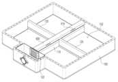
도 1은 본 발명의 배터리 팩(10)에 대한 분해 사시도, 도 2는 팩 케이스(100)를 도시한 도면, 그리고 도 3은 배터리 블록(200)에 대한 도면이다.FIG. 1 is an exploded perspective view of the
도 1을 참조하면, 본 발명의 배터리 팩(10)은 팩 케이스(100)와 복수의 배터리 블록(200)을 포함한다. 도 2에는 팩 케이스(100)가 도시되어 있는데, 팩 케이스(100)는 센터 빔(110)과, 센터 빔(110)에 교차하는 크로스 빔(120)으로 구획되는 복수의 수납공간(102)을 구비한다. 도시된 팩 케이스(100)는, 좌우방향으로 연장된 크로스 빔(120)과, 크로스 빔(120)을 가로지르면서 전후방향으로 연장된 센터 빔(110)에 의해 총 4개의 수납공간(102)이 형성되어 있다. 그리고, 팩 케이스(100)의 내부는 팩 케이스(100)의 상면을 덮는 팩 커버(140)에 의해 밀봉된다.Referring to FIG. 1, the
여기서, 도시된 팩 케이스(100)는 하나의 예로서, 크로스 빔(120)과 센터 빔(110)의 개수를 늘려 4개를 초과하는 더 많은 개수의 수납공간(102)을 마련하는 것도 가능하다. 그리고, 크로스 빔(120)의 중앙은 센터 빔(110)에 의해 좌우로 분할되어 있는데, 크로스 빔(120)과 센터 빔(110)이 상호 결합하여 격자구조를 이룸으로써 팩 케이스(100)의 강성을 보강하게 된다.Here, the
팩 케이스(100)에 4개로 마련된 각각의 수납공간(102)에는 도 3의 배터리 블록(200)이 하나씩 수용되고, 각 배터리 블록(200)에는 10개의 배터리 셀(210)이 하나로 모여있다. 따라서, 예시된 배터리 팩(10)은 총 40개의 배터리 셀(210)이 모여 하나의 팩을 구성하고 있다.Each of the four
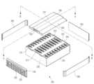
모든 배터리 블록(200)은 동일한 구성을 가지는데, 도 3을 참조하면, 각 배터리 셀(210)은 전지 케이스의 상면에 벤팅장치(212)가 구비되어 있으며, 복수의 배터리 셀(210)이 일렬로 정렬되고 하나로 묶여 블록을 이룬다.All battery blocks 200 have the same configuration. Referring to FIG. 3, each
배터리 블록(200)은, 일렬로 정렬된 배터리 셀(210)의 양 측면에 결합하는 한 쌍의 사이드 케이스(220)와, 전면에 결합하는 프론트 케이스(230), 그리고 후면에 결합하는 리어 케이스(240)를 포함한다. 그리고, 배터리 블록(200)의 강성을 확보하기 위한 한 쌍의 엔드 플레이트(250)가 프론트 케이스(230)와 리어 케이스(240)를 각각 덮고, 한 쌍의 사이드 고정 플레이트(260)가 사이드 케이스(220)를 덮으면서 그 양단이 엔드 플레이트(250)에 고정된다. 여기서, 엔드 플레이트(250)는 무게는 줄이면서 강성은 늘릴 수 있는 리브 구조를 포함할 수 있다.The
또한, 배터리 블록(200)은 상면에 일렬로 정렬된 복수의 벤팅장치(212)를 밀폐하도록 결합하는 벤팅 덕트(500)를 포함하고 있다. 벤팅 덕트(500)는, 과열된 배터리 셀(210)의 내부 압력에 의해 파열된 벤팅장치(212)를 통해 분출되는 고온 가스 및/또는 입자가 주변으로 확산되지 않고 정해진 방향으로만 유동하도록 유도하는 통로 역할을 한다.In addition, the
도 1에 도시된 바와 같이, 배터리 블록(200)은 벤팅 덕트(500)의 출구(530)가 센터 빔(110)을 향하는 방향으로 하여 팩 케이스(100)의 수납공간(102) 안에 안착된다. 여기서, 배터리 블록(200)에 있어서 벤팅 덕트(500)의 출구(530)가 배치되는 면을 전면으로 정의한다면, 배터리 블록(200)은 그 전면이 센터 빔(110)을 향하도록 팩 케이스(100) 내에 배치되는 것이다.As shown in FIG. 1, the
한편, 본 발명의 제1 실시형태에서, 각각의 배터리 블록(200)은, 액체가 함침된 흡수재(310)가 밀봉 수납된 흡열 파우치(300)가 복수의 배터리 셀(210) 사이에 배치되어 있다. 도 4는 배터리 셀(210) 사이에 흡열 파우치(300)가 배치되는 실시형태를 보여주고 있다.Meanwhile, in the first embodiment of the present invention, in each
흡열 파우치(300)에 수납된 흡수재(310)에 다량으로 함침되어 있는 액체는 배터리 셀(210)에서 발생하는 열을 흡수하여 냉각하는 역할을 한다. 또한, 흡열 파우치(300) 내부의 액체의 온도가 흡열과정에서 비등점을 초과하면 기화되며, 액체에서 기체로의 상변화에 따른 부피 증가로 인해 흡열 파우치(300)에는 내압이 작용하게 된다.A large amount of liquid impregnated in the
흡열 파우치(300) 내부의 액체가 충분히 기화되어 내압이 기준을 초과하면 흡열 파우치(300)는 파단되고, 파단된 흡열 파우치(300)에서 분출되는 증기 역시 배터리 셀(210)을 냉각하는데 이용된다. 특히, 흡열 파우치(300)의 파열 시점은, 배터리 셀(210)의 벤팅장치(212)가 파단되어 고온 가스 및/또는 입자가 분출되었을 때에 동기화되는 것이 바람직할 수 있다. 즉, 벤팅장치(212)에서 뿜어나오는 고온 가스와 입자가 흡열 파우치(300)의 증기와 혼합되어 급격히 열을 잃도록 함으로써 열 전파 발생을 억제하고 외부 발화의 위험을 방지하는데 기여할 수 있다. 흡열 파우치(300)가 파단되는 시점과 증기 배출의 방향을 제어할 수 있도록, 흡열 파우치(300)는 내압이 기준치를 초과하면 우선적으로 파단되는 제1 취약부(330)를 구비한다.When the liquid inside the heat-absorbing
흡열 파우치(300)의 몸체(포장재)는 유연한 라미네이트 시트를 이용하여 제조될 수 있으며, 라미네이트 시트는 알루미늄 박막층, 알루미늄 박막층의 내측에 형성된 내부 수지층, 그리고 알루미늄 박막층의 외측에 형성된 외부 수지층을 포함하는 3층 이상의 구조일 수 있다. 예를 들어, 내부 수지층은 무연신 폴리프로필렌(casted polypropylene, CPP) 또는 폴리프로필렌(PP)일 수 있고, 외부 수지층은 폴리에틸렌 테레프탈레이트(PET) 또는 나일론일 수 있다.The body (packaging material) of the
흡열 파우치(300)의 제1 취약부(330)는, 열융착 실링부(320)의 밀봉 강도를 국부적으로 낮춤으로써 액체의 기화에 따른 내압 증가에 의해 우선적으로 파단되도록 구성될 수 있다. 즉, 제1 취약부(330)는 열융착 실링부(320)의 열융착 강도를 주변보다 낮게 만드는 방식으로 형성될 수 있다. 예를 들어, 제1 취약부(330)는 주변보다 두께를 얇게 만들거나 노치를 형성하여 강도를 낮추거나, 또는 내구성을 유지하는 알루미늄 박막층을 국부적으로 제거함으로써 형성될 수 있다.The first
이와 같이 흡열 파우치(300)에 제1 취약부(330)가 구비됨으로써, 어떤 배터리 셀(210)에 열 폭주 현상이 발생하여 과열될 경우 흡열 파우치(300) 내의 흡수재(310)에 함침된 액체가 열을 흡수하여 기화되고, 기화된 가스의 내압이 설정된 압력을 초과, 즉 제1 취약부(330)의 파열강도를 초과하면 제1 취약부(330)가 파단되어 기체를 분출한다.In this way, the
다만, 흡열 파우치(300)는 포장재인 라미네이트 시트의 유연성으로 인해 그 형태를 정확히 동일하게 유지하는 것이 곤란하다는 단점이 있다. 이러한 흡열 파우치(300)의 비정형성은 흡열 파우치(300)를 배터리 셀(210) 사이마다 배치할 때의 수치 균일성에 부정적인 영향을 미친다. 본 발명의 제1 실시형태는, 유연한 흡열 파우치(300)의 사이즈와 형태를 정형화할 수 있는 파우치 카트리지(400)를 더 포함할 수 있다. 도 5는 파우치 카트리지(400)를 포함하는 흡열 파우치(300)를 도시한 도면이다.However, the
도 5를 참조하면, 파우치 카트리지(400)는 흡열 파우치(300)의 테두리를 따라 형성된 열융착 실링부(320)를 양측에서 결속하는 한 쌍의 테두리 프레임(410)을 포함한다. 테두리 프레임(410)은 알루미늄 등의 금속이나 폴리카보네이트 등의 합성수지로 제조될 수 있으며, 파우치 카트리지(400)는 충분한 강도를 지니고 있어 그 형태가 양호하게 유지된다.Referring to FIG. 5, the
이와 같이, 구조체인 테두리 프레임(410)이 흡열 파우치(300)의 테두리를 고정함에 따라 흡열 파우치(300)의 전체적인 형태와 사이즈는 상당히 균일하고 정형화된다. 따라서, 파우치 카트리지(400)가 장착된 흡열 파우치(300)는 배터리 셀(210) 사이사이마다 정확한 위치와 크기로 배치되는 것을 보장하고, 이는 곧 복수의 배터리 셀(210)과 흡열 파우치(300)를 내장하는 배터리 블록(200)을 구성할 때 제조상의 공차나 편차를 용이하게 관리할 수 있게 한다.In this way, as the
그리고, 흡열 파우치(300)의 열융착 실링부(320) 상에 제1 취약부(330)가 구비된 것에 대응하여, 테두리 프레임(410)에는 제1 취약부(330)에 대응하는 영역에 벤팅 유도홀(420)이 구비된다. 벤팅 유도홀(420)은 테두리 프레임(410)의 내면과 외부를 연통시키고, 이에 따라 파단된 제1 취약부(330)에서 분출하는 기체는 벤팅 유도홀(420)을 통해 외부로 분사된다. 즉, 흡열 파우치(300)에서 나온 기체는 벤팅 유도홀(420)에 의해 정해진 방향으로 유도 분출된다.In response to the fact that the first
특히 배터리 셀(210) 사이에 흡열 파우치(300)가 배치되는 본 발명에 있어서, 벤팅 유도홀(420)은 벤팅장치(212)에 인접 배치되는 것이 바람직할 것이다. 배터리 셀(210)의 구조 붕괴를 막기 위해 파단된 벤팅장치(212)에서는 고온 가스와 입자가 다량으로 분출되는바, 제1 취약부(330) 및 벤팅 유도홀(420)의 위치가 벤팅장치(212)에 대응하도록 배치하는 것이 발화 억제에 효과적일 것이다.In particular, in the present invention in which the
아울러 흡열 파우치(300)는 파우치 카트리지(400)에 의해 가려지지 않는 표면에 제2 취약부(340)를 더 구비할 수 있다. 예를 들어, 제2 취약부(340)는 벤팅 유도홀(420)의 직하방에 위치하여 유도 벤팅에 대응하는 방향으로 기체를 분출할 수 있다. 참고로, 제2 취약부(340)는 제1 취약부(330)와 동일한 방식으로 만들어질 수 있다.In addition, the heat-absorbing
제2 취약부(340)는 추가적인 기체 출구를 제공하는 것으로서, 예컨대 제1 취약부(330) 및 벤팅 유도홀(420)을 통한 기체의 분출이 불충분할 때의 추가 출구를 제공하거나, 또는 흡열 파우치(300)의 내압이 상정된 수준을 초과하여 상승할 때의 안전 출구로서 마련될 수 있다. 이런 점에서, 제1 취약부(330)가 우선 파단된 이후에 제2 취약부(340)가 파단되도록, 제2 취약부(340)의 파열강도를 제1 취약부(330)의 파열강도보다 높게 설계할 수 있다.The second
그리고, 도 5를 다시 참조하면, 흡열 파우치(300)의 열융착 실링부(320) 상에는 하나 이상의 가이드 홀(322)이 구비되고, 한 쌍의 테두리 프레임(410) 중 적어도 어느 하나에는 가이드 홀(322)에 삽입되는 돌기(430)가 구비되어 있다.And, referring again to FIG. 5, one or more guide holes 322 are provided on the heat
이에 따라, 흡열 파우치(300)와 테두리 프레임(410)을 상호 결합할 때, 흡열 파우치(300)의 가이드 홀(322)에 테두리 프레임(410)의 돌기(430)가 삽입됨으로써 흡열 파우치(300)와 테두리 프레임(410)이 정확하게 상호 정렬된다. 또한, 테두리 프레임(410)의 돌기(430)가 흡열 파우치(300)의 가이드 홀(322)을 관통함으로써 흡열 파우치(300)의 고정력이 향상된다. 즉, 흡열 파우치(300)에 직접 외력이 작용하더라도 돌기(430)가 열융착 실링부(320)를 관통하여 지지하므로, 열융착 실링부(320)의 파단강도 이내의 외력에 대해서는 흡열 파우치(300)가 테두리 프레임(410)에서 분리되지 않게 된다.Accordingly, when the heat-absorbing
한편, 본 발명의 제1 실시형태에서, 흡수재(310)는 고흡수성 매트릭스, 예를 들어 고흡수성 폴리머(Super Absorbent Polymer, SAP) 또는 고흡수성 섬유(Super Absorbent Fiber, SAF)를 포함하는 흡수재(310)일 수 있다. 고흡수성 매트릭스는 다공질 또는 섬유질로 모세관 현상을 발현함으로써 다량의 액체를 흡수하는 것이 가능하며, 고흡수성 섬유는 고흡수성 수지를 가공하여 부직포와 같은 섬유의 형태로 제조할 수 있다.Meanwhile, in the first embodiment of the present invention, the
본 발명에서 고흡수성 수지 및 이로부터 제조되는 고흡수성 섬유의 구체적인 종류는 특별히 제한되지 않고, 유체, 특히 물에 대한 흡수 능력이 뛰어난 것이라면 제한 없이 사용할 수 있다. 본 발명에서는 고흡수성 수지의 예로서, 폴리아크릴산, 폴리아크릴산염, 폴리아크릴산염 그래프트 중합체, 전분, 가교된 카르복시메틸화 셀룰로오스, 아크릴산 공중합체, 가수분해된 전분-아크릴니트릴 그래프트 공중합체, 전분-아크릴산 그래프트 공중합체, 비누화 비닐 아세테이트-아크릴산 에스테르 공중합체, 가수분해된 아크릴로니트릴 공중합체, 가수분해된 아크릴아미드 공중합체, 에틸렌-말레산 무수물 공중합체, 이소부틸렌-말레산 무수물 공중합체, 폴리비닐술폰산, 폴리비닐포스폰산, 폴리비닐인산, 폴리비닐황산, 술폰화 폴리스티렌, 폴리비닐아민, 폴리디알킬아미노알킬(메타)아크릴아미드, 폴리에틸렌이민, 폴리알릴아민, 폴리알릴구아니딘, 폴리디메틸디알릴암모늄 히드록시드, 4차화 폴리스티렌 유도체, 구아니딘-변성 폴리스티렌, 4차화 폴리(메타)아크릴아미드, 폴리비닐구아니딘 및 이들의 혼합물로 이루어진 군으로부터 선택되는 하나 이상을 들 수 있고, 바람직하게는 가교화된 폴리아크릴산 염, 가교화된 폴리아크릴산 및 가교화된 아크릴산 중공합체로 이루어진 군으로부터 선택되는 하나 이상을 들 수 있으나, 이에 제한되는 것은 아니다.In the present invention, the specific type of the superabsorbent polymer and the superabsorbent fiber produced therefrom is not particularly limited, and any type that has an excellent absorption ability for fluid, especially water, can be used without limitation. In the present invention, examples of superabsorbent resins include polyacrylic acid, polyacrylate, polyacrylate graft polymer, starch, cross-linked carboxymethylated cellulose, acrylic acid copolymer, hydrolyzed starch-acrylnitrile graft copolymer, and starch-acrylic acid graft. Copolymer, saponified vinyl acetate-acrylic acid ester copolymer, hydrolyzed acrylonitrile copolymer, hydrolyzed acrylamide copolymer, ethylene-maleic anhydride copolymer, isobutylene-maleic anhydride copolymer, polyvinylsulfonic acid , polyvinylphosphonic acid, polyvinyl phosphoric acid, polyvinyl sulfate, sulfonated polystyrene, polyvinylamine, polydialkylaminoalkyl (meth)acrylamide, polyethyleneimine, polyallylamine, polyallylguanidine, polydimethyldiallylammonium hydride. At least one selected from the group consisting of oxide, quaternized polystyrene derivatives, guanidine-modified polystyrene, quaternized poly(meth)acrylamide, polyvinylguanidine, and mixtures thereof, preferably crosslinked polyacrylic acid. One or more selected from the group consisting of salts, crosslinked polyacrylic acid, and crosslinked acrylic acid hollow polymers may be included, but are not limited thereto.
본 발명에서 고흡수성 수지로 사용되는 아크릴산 공중합체의 종류는 특별히 제한되지 않지만, 바람직하게는 아크릴산 단량체와 말레산, 이타콘산, 아크릴아미드, 2-아크릴아미드-2-메틸프로판술폰산, 2-(메타)아크릴로일에탄술폰산, 2-히드록시에틸(메타)아크릴레이트 및 스티렌술폰산으로 이루어진 군으로부터 선택되는 하나 이상의 공단량체를 포함하는 공중합체일 수 있다.The type of acrylic acid copolymer used as the superabsorbent polymer in the present invention is not particularly limited, but is preferably acrylic acid monomer and maleic acid, itaconic acid, acrylamide, 2-acrylamide-2-methylpropanesulfonic acid, 2-(meth ) It may be a copolymer containing one or more comonomers selected from the group consisting of acryloylethanesulfonic acid, 2-hydroxyethyl (meth)acrylate, and styrenesulfonic acid.
본 발명에서 고흡수성 수지는 물에 대한 흡수량이 10 g/g 내지 500 g/g, 바람직하게는 50 g/g 내지 200 g/g일 수 있으나, 이에 제한되는 것은 아니다. 즉, 고흡수성 수지 1 g당 물 10 g 내지 500 g, 바람직하게는 50 g 내지 200 g을 흡수할 수 있다.In the present invention, the superabsorbent polymer may have a water absorption amount of 10 g/g to 500 g/g, preferably 50 g/g to 200 g/g, but is not limited thereto. That is, 10 g to 500 g of water, preferably 50 g to 200 g, can be absorbed per 1 g of superabsorbent polymer.
본 발명에서 고흡수성 수지의 물에 대한 흡수량이 많을수록 냉각 효과의 지속 시간을 향상시킬 수 있으나, 500 g/g을 초과하면 고흡수성 수지의 유동성이 증가하여 형태를 유지하기 어려워 효과적인 냉각을 발휘할 수 없고, 10 g/g 미만이면 냉각 효과의 지속 시간이 너무 짧아 비효율적일 수 있다.In the present invention, the greater the water absorption of the superabsorbent polymer, the longer the cooling effect can be improved. However, if it exceeds 500 g/g, the fluidity of the superabsorbent polymer increases and it is difficult to maintain its shape, making effective cooling impossible. , if it is less than 10 g/g, the duration of the cooling effect may be too short and ineffective.
그리고, 본 발명의 제1 실시형태에서, 흡수재(310)에 함침된 액체는 물인 것이 바람직할 수 있다. 물은 쉽게 구할 수 있는 액체 중에서 비열과 잠열이 가장 큰 물질에 해당한다. 따라서, 흡수재(310)에 수용된 물은 상온에서 시작하여 기체로 상변화하는 전체 과정에서 다량의 열을 흡수하므로, 본 발명의 흡열 파우치(300)에 적용하기에 적합하다.And, in the first embodiment of the present invention, it may be preferable that the liquid impregnated in the
또한, 흡수재(310)에 함침된 물에는 소화기능을 강화할 수 있는 첨가제가 혼합될 수 있다. 예를 들어, 물에 혼합된 첨가제는 물의 표면장력을 낮추는 물질이거나, 또는 소화약제일 수 있다. 물의 표면장력을 낮추는 물질로는 습윤제나 계면활성제를 예로 들 수 있으며, 물의 표면장력이 낮아지면 물의 침투효과가 상승함으로써 가열전극이나 발화입자 등의 점화원에 대한 소화효과가 강화된다.Additionally, additives that can enhance the fire extinguishing function may be mixed with the water impregnated in the
소화약제는 그 자체가 소화기능을 발휘하는 약제를 통칭하는 것으로서, 현재 상용화된 각종 분말 소화약재나 액체 소화액재 등이 적용될 수 있다. 예를 들어, 상품명 F-500 EA(제조사 HAZARD CONTROL TECHNOLOGIES, INC.)의 소화약제가 물에 첨가될 수 있다.A fire extinguishing agent is a general term for a drug that exerts a fire extinguishing function itself, and various currently commercialized powder fire extinguishing agents or liquid fire extinguishing fluids can be applied. For example, fire extinguishing agent under the trade name F-500 EA (manufacturer HAZARD CONTROL TECHNOLOGIES, INC.) may be added to the water.
이상과 같은 구성의 흡열 파우치(300)를 포함하는 배터리 블록(200)의 구성은 도 6 및 도 7을 통해 더욱 명확히 이해할 수 있다.The configuration of the
도 6은 도 3의 "A-A" 선을 따라 절개한 단면으로서, 흡열 파우치(300)의 제1 취약부(330) 및 제2 취약부(340)의 상방은 벤팅 덕트(500)에 대해 밀폐되어 있다. 이에 따라, 흡열 파우치(300)의 제1 취약부(330) 및/또는 제2 취약부(340)가 파단되어 내부의 기체가 벤팅 덕트(500)를 향하여 분출되면, 분출된 기체의 대부분은 밀폐된 벤팅 덕트(500) 안에서 유동하여 최종적으로는 벤팅 덕트(500)의 출구(530)로 배출된다.FIG. 6 is a cross-section taken along line “A-A” of FIG. 3 , and the upper portions of the first
그리고, 도 7은 도 3의 "B-B" 선을 따라 절개한 단면도이다. 도시된 실시형태에서, 벤팅 덕트(500)는, 유동공간을 형성하는 덕트부(510)와, 덕트부(510)에 대해 벤팅장치(212)를 밀봉하는 밀폐부(520)를 포함하고 있다. 즉, 덕트부(510)는 증기나 고온 가스 등의 기체, 고온 입자 등이 유동하는 공간을 이루고 있으며, 덕트부(510)에서 연장된 밀폐부(520)가 배터리 셀(210)의 상면에 밀착되어 덕트부(510)를 밀폐하고 있다. 밀폐성을 향상하기 위해, 밀폐부(520)와 배터리 셀(210) 사이에는 실리콘 패드와 같은 실링부재(522)가 구비될 수 있다.And, Figure 7 is a cross-sectional view taken along the line "B-B" in Figure 3. In the illustrated embodiment, the venting
또한, 도 7에 나타난 것처럼, 흡열 파우치(300)의 제1 취약부(330) 및 제2 취약부(340)의 위치는 벤팅장치(212)의 위치에 대응하고 있으며, 열 폭주시의 고온에 의해 벤팅 덕트(500)가 손상되거나 붕괴되는 것을 방지하기 위하여 덕트부(510)의 내면에는 운모판과 같은 단열부재(512)가 구비될 수 있다.In addition, as shown in FIG. 7, the positions of the first
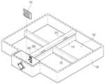
유도 벤팅을 위해 배터리 블록(200)에 마련된 벤팅 덕트(500)의 출구(530)는 벤팅 튜브(600)에 연결된다. 본 발명의 배터리 팩(10)에서, 4개의 배터리 블록(200)은 하나의 벤팅 튜브(600)를 공유하고 있으며, 어떤 배터리 블록(200)에서 열 폭주가 발생하더라도 모든 가스와 입자는 벤팅 튜브(600)를 통해 외부로 배출된다.The
도 2를 살펴보면, 센터 빔(110)의 높이는 크로스 빔(120)의 높이보다 낮게 설계되어 있다. 이러한 센터 빔(110) 상방의 여유공간에는 중공형의 벤팅 튜브(600)가 센터 빔(110)에 나란하게 배치되어 있다.Looking at Figure 2, the height of the
벤팅 튜브(600)는, 배터리 블록(200)을 구성하는 복수 배터리 셀(210)의 상면에 구비된 벤팅장치(212)를 밀폐하는 벤팅 덕트(500)에 대해 연장된 유로를 형성한다. 도 8은 벤팅 튜브(600)와 벤팅 덕트(500)의 연결 구조를 도시한 도면으로서, 벤팅 튜브(600)는 벤팅 덕트(500)에 대응하는 높이에 위치하고, 배터리 블록(200)의 전면에 위치한 벤팅 덕트(500)의 출구(530)는 벤팅 튜브(600)에 마련된 연결구(610)에 접속된다.The venting
벤팅 덕트(500)는 과열된 배터리 셀(210)의 내부 압력에 의해 파열된 벤팅장치(212)를 통해 분출되는 고온 가스 및/또는 입자가 주변으로 확산되지 않고 정해진 방향으로만 유동하도록 유도하는 통로 역할을 하고, 이렇게 유도된 가스와 입자의 유동은 벤팅 튜브(600)를 통해 배터리 팩(10)의 외부로 배출된다.The venting
전술한 바와 같이, 벤팅장치(212)를 통해 분출되는 고온 가스 및/또는 입자는 흡열 파우치(300)에서 생산된 증기(기체)와 혼합되면서 온도가 급격히 떨어지고, 이렇게 발화점 이하로 온도가 내려간 가스와 입자가 배터리 팩(10) 밖으로 배출됨으로써 외부 화재의 위험이 효과적으로 방지된다.As described above, the temperature of the high-temperature gas and/or particles ejected through the
[제2 실시형태][Second Embodiment]
도 9는 벤팅 튜브(600)의 단면을 도시한 도면이다. 본 발명의 제2 실시형태에서, 벤팅 튜브(600) 내부에는 매쉬 구조체(640)가 구비되어 있다.Figure 9 is a diagram showing a cross section of the venting
매쉬 구조체(640)는 다수의 작은 구멍을 가진 금속재질의 구조체를 의미하는 것으로서, 본 발명에서는 매쉬 구조체(640)가 필터링과 소염(消焰) 기능을 발휘한다.The
열 폭주에 의한 내압 상승에 의해 파단된 벤팅장치(212)에서는 고온의 가스와 입자가 분출된다. 매쉬 구조체(640)의 필터링 기능은 고온 입자에 작용하며, 매쉬 구조체(640)에 의해 직경이 큰 고온 입자가 걸러진다. 특히, 특정 사이즈를 초과하는 고온 입자는 외부 화재의 점화원으로 작용하기에, 매쉬 구조체(640)에 의한 필터링을 통해 외부 발화의 원인을 효과적으로 제거할 수 있다.High-temperature gas and particles are ejected from the
또한, 매쉬 구조체(640)는 연소되는 기체 혼합물에서 발생하는 열을 흡수하여 발산함으로써 주변의 기체가 자연 발화온도에 오르지 않도록 연소온도를 낮추어 주는 역할을 한다. 이것은 고온의 기체가 매쉬 구조체(640)를 통과하면서 금속재질의 다공 구조에 열을 빼앗기기 때문이다. 따라서, 배터리 셀(210)의 열폭주에 의해 발생한 화염은 벤팅 튜브(600) 안의 매쉬 구조체(640)를 통과하면서는 더 이상 화염이 유지하지 못할 만큼의 열량을 빼앗기게 되고, 이로써 열 전파 현상이나 외부 화재가 억제된다.In addition, the
매쉬 구조체(640)는 열에 강한 금속재질, 예를 들어 내열성 스테인리스스틸로 만들어 질 수 있다. 내열 스테인리스스틸은 X10CrAlSi7, X10CrAl13, X10CrAl18 및 X18CrN28과 같은 페라이트계 스테인리스스틸 합금이나, X15CrNiSi20-12, X15CrNiSi25-20, X15CrNiSi25-21 및 X12CrNiTi18-10과 같은 오스테나이트계 스테인리스스틸 합금, 또는 NiCr15Fe, NiCr23Fe, NiCr22Mo9Nb, NiCr21Mo 및 NiCr28FeSiCe와 같은 니켈-크롬 스테인리스스틸 합금일 수 있다.The
그리고, 도 10은 벤팅 튜브(600)의 출구(630)를 도시한 도면이다. 벤팅 튜브(600)의 출구(630)는 팩 케이스(100)의 벤팅 홀(130)에 연결되어 있으며, 벤팅 홀(130)의 출구에는 매쉬 커버(132)가 구비되어 있다. 매쉬 커버(132) 역시 추가적인 필터링과 소염 기능을 제공한다. 즉, 매쉬 구조체(640)와 매쉬 커버(132)에 의해 2단계로 필터링을 하고 화염을 제거한다.And, Figure 10 is a diagram showing the
여기서, 매쉬 구조체(640)의 체눈의 크기를 매쉬 커버(132)의 체눈의 크기보다 작게 만들 수 있다. 이는 벤팅 튜브(600)의 출구(630)에 배치되는 매쉬 커버(132)의 체눈 크기를 더 작게 만들면, 벤팅 튜브(600)에서 걸러지고 남은 작은 입자가 매쉬 커버(132)에 쌓여 결과적으로 벤팅 튜브(600)를 폐색할 수 있기 때문이다.Here, the size of the
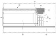
한편, 도 11은 배터리 블록(200)이 벤팅 튜브(600)를 지지하는 일 실시형태를 도시한 도면이다.Meanwhile, FIG. 11 is a diagram illustrating an embodiment in which the
센터 빔(110)은 팩 케이스(100)의 강도를 보강하기 위하여 팩 케이스(100)의 바닥면에 접합되어 있다. 따라서, 배터리 블록(200)의 엔드 플레이트(250)에 돌출 형성된 브래킷(252)이 센터 빔(110)의 상면에 접촉함으로써 배터리 블록(200)을 지지할 수 있다. 또한, 브래킷(252)과 센터 빔(110) 사이를 체결함으로써 배터리 블록(200)을 더욱 견고하게 고정하는 것도 가능하다.The
이에 비해, 센터 빔(110)에 이격되어 떠 있는 벤팅 튜브(600)는 양단이 팩 케이스(100)에 접합되고, 벤팅 덕트(500)와 측면 일부분이 연결된 구조이기 때문에, 팩 케이스(100)의 바닥에 접합되어 있는 센터 빔(110)에 비해 상대적으로 하중에 약한 구조라 할 수 있다. 제2 실시형태에서는, 배터리 블록(200)의 엔드 플레이트(250) 상부에 벤팅 튜브(600)의 측면이 접촉 지지됨으로써 벤팅 튜브(600)의 하중 지지구조를 보완하고 있다.In contrast, the venting
도 11을 참조하면, 벤팅 튜브(600)의 측면에는 단차(620)가 형성되어 있어 전체적인 단면 형태가 "T"자를 이루고 있다. 이러한 벤팅 튜브(600)의 측면 단차(620)는 엔드 플레이트(250)의 평평한 상부에 접촉하게 되고, 이를 통해 벤팅 튜브(600)의 지지구조가 개선된다.Referring to FIG. 11, a
이처럼 벤팅 튜브(600)의 지지구조가 개선되면, 급작스러운 벤팅장치(212)의 파단에 의해 벤팅 튜브(600) 안에서 강한 압력 파동이 발생하더라도 배터리 블록(200)과의 연결이 느슨해지는 등의 문제가 방지된다.If the support structure of the venting
이상, 도면과 실시예 등을 통해 본 발명을 보다 상세히 설명하였다. 그러나, 본 명세서에 기재된 도면 또는 실시예 등에 기재된 구성은 본 발명의 일 실시예에 불과할 뿐이고 본 발명의 기술적 사상을 모두 대변하는 것은 아니므로, 본 출원시점에 있어서 이들을 대체할 수 있는 다양한 균등물과 변형예들이 있을 수 있음을 이해하여야 한다.Above, the present invention has been described in more detail through drawings and examples. However, since the configurations described in the drawings or examples described in this specification are only one embodiment of the present invention and do not represent the entire technical idea of the present invention, at the time of filing this application, various equivalents and It should be understood that variations may exist.
10: 배터리 팩100: 팩 케이스
102: 수납공간110: 센터 빔
120: 크로스 빔130: 벤팅 홀
132: 매쉬 커버140: 팩 커버
200: 배터리 블록210: 배터리 셀
212: 벤팅장치220: 사이드 케이스
230: 프론트 케이스240: 리어 케이스
250: 엔드 플레이트252: 브래킷
260: 사이드 고정 플레이트300: 흡열 파우치
310: 흡수재320: 열융착 실링부
322: 가이드 홀330: 제1 취약부
340: 제2 취약부400: 파우치 카트리지
410: 테두리 프레임420: 벤팅 유도홀
430: 돌기500: 벤팅 덕트
510: 덕트부512: 단열부재
520: 밀폐부522: 실링부재
530: 벤팅 덕트 출구600: 벤팅 튜브
610: 연결구620: 측면 단차
630: 벤팅 튜브 출구640: 매쉬 구조체10: Battery pack 100: Pack case
102: Storage space 110: Center beam
120: cross beam 130: venting hole
132: Mesh cover 140: Pack cover
200: battery block 210: battery cell
212: venting device 220: side case
230: front case 240: rear case
250: end plate 252: bracket
260: Side fixing plate 300: Heat absorbing pouch
310: Absorber 320: Heat fusion sealing part
322: Guide hole 330: First vulnerable part
340: second vulnerable portion 400: pouch cartridge
410: Border frame 420: Venting guide hole
430: Protrusion 500: Venting duct
510: duct part 512: insulation member
520: sealing portion 522: sealing member
530: venting duct outlet 600: venting tube
610: Connector 620: Side step
630: venting tube outlet 640: mesh structure
Claims (15)
Translated fromKorean상기 팩 케이스의 수납공간에 각각 수용되고, 상면에 벤팅장치가 구비된 복수의 배터리 셀이 일렬로 정렬된 복수의 배터리 블록;
상기 배터리 블록의 상면에 일렬로 정렬된 복수의 벤팅장치를 밀폐하도록 결합하고, 상기 센터 빔을 향하는 방향으로 출구가 형성된 벤팅 덕트; 및
상기 센터 빔을 따라 배치되고, 상기 벤팅 덕트의 출구와 연통하는 연결구를 구비하며, 길이방향의 적어도 어느 일단이 출구를 형성하는 중공 형태의 벤팅 튜브;
를 포함하는 배터리 팩.A pack case having a center beam and a plurality of storage spaces divided by a cross beam that intersects the center beam;
a plurality of battery blocks each accommodated in a storage space of the pack case and having a plurality of battery cells arranged in a row, each of which has a venting device on its upper surface;
a venting duct that seals and combines a plurality of venting devices arranged in a row on the upper surface of the battery block and has an outlet in a direction toward the center beam; and
a hollow venting tube disposed along the center beam, having a connector communicating with an outlet of the venting duct, and at least one end in the longitudinal direction forming an outlet;
Battery pack containing.
각각의 배터리 블록은,
액체가 함침된 흡수재가 밀봉 수납된 흡열 파우치가 상기 복수의 배터리 셀 사이에 배치된 것을 특징으로 하는 배터리 팩.According to paragraph 1,
Each battery block is,
A battery pack, characterized in that a heat absorbing pouch in which an absorbent material impregnated with liquid is sealed and stored is disposed between the plurality of battery cells.
상기 흡열 파우치의 테두리를 따라 형성된 열융착 실링부를 양측에서 결속하는 한 쌍의 테두리 프레임을 포함하는 파우치 카트리지를 더 포함하는 배터리 팩.According to paragraph 2,
A battery pack further comprising a pouch cartridge including a pair of edge frames that bind heat-fusion sealing portions formed along the edge of the heat-absorbing pouch on both sides.
상기 열융착 실링부 상에는 상대적으로 파열강도가 낮은 제1 취약부가 구비되고,
상기 테두리 프레임에는 상기 제1 취약부에 대응하는 영역에 벤팅 유도홀이 구비되는 것을 특징으로 하는 배터리 팩.According to paragraph 3,
A first weak portion having a relatively low bursting strength is provided on the heat fusion sealing portion,
A battery pack, characterized in that the edge frame is provided with a venting guide hole in an area corresponding to the first vulnerable portion.
상기 흡열 파우치는,
상기 파우치 카트리지에 의해 가려지지 않는 표면에 상대적으로 파열강도가 낮은 제2 취약부가 구비되는 것을 특징으로 하는 배터리 팩.According to clause 4,
The heat absorbing pouch,
A battery pack, characterized in that a second vulnerable portion having a relatively low bursting strength is provided on a surface that is not covered by the pouch cartridge.
상기 제2 취약부는 상기 벤팅 유도홀의 직하방에 위치하는 것을 특징으로 하는 배터리 팩.According to clause 5,
The second vulnerable portion is a battery pack characterized in that it is located directly below the venting guide hole.
상기 제1 취약부 및 제2 취약부의 위치는 상기 벤팅장치의 위치에 대응하고,
상기 제1 취약부 및 제2 취약부의 상방은 상기 벤팅 덕트에 대해 밀폐되는 것을 특징으로 하는 배터리 팩.According to clause 5,
The positions of the first and second vulnerable parts correspond to the position of the venting device,
A battery pack, characterized in that the upper portions of the first and second vulnerable portions are sealed with respect to the venting duct.
상기 흡수재에 함침된 액체는 열을 흡수하여 기체로 상 변화를 일으키고,
기체의 압력이 상기 제1 취약부 또는 제2 취약부의 파열강도를 초과하면 상기 제1 취약부 또는 제2 취약부가 파단되어 상기 흡열 파우치 내부의 기체가 상기 벤팅 덕트를 향하여 분출되는 것을 특징으로 하는 배터리 팩.In clause 7,
The liquid impregnated in the absorbent material absorbs heat and causes a phase change to gas,
When the pressure of the gas exceeds the rupture strength of the first or second vulnerable portion, the first or second vulnerable portion is ruptured and the gas inside the heat absorbing pouch is ejected toward the venting duct.
상기 벤팅 덕트는,
유동공간을 형성하는 덕트부와, 상기 벤팅장치를 밀봉하는 밀폐부를 포함하고,
상기 덕트부의 내면에는 단열부재가 구비되는 것을 특징으로 하는 배터리 팩.According to paragraph 1,
The venting duct is,
It includes a duct part forming a flow space and a sealing part sealing the venting device,
A battery pack, characterized in that an insulation member is provided on the inner surface of the duct portion.
상기 밀폐부와 상기 배터리 셀 사이에는 실링부재가 구비되는 것을 특징으로 하는 배터리 팩.According to clause 9,
A battery pack, characterized in that a sealing member is provided between the sealing portion and the battery cell.
상기 벤팅 튜브 내부에는 매쉬 구조체가 구비되는 것을 특징으로 하는 배터리 팩.According to paragraph 1,
A battery pack characterized in that a mesh structure is provided inside the venting tube.
상기 벤팅 튜브의 출구는 상기 팩 케이스의 벤팅 홀에 연결되는 것을 특징으로 하는 배터리 팩.According to clause 11,
A battery pack, characterized in that the outlet of the venting tube is connected to the venting hole of the pack case.
상기 벤팅 홀의 출구에는 매쉬 커버가 구비되는 것을 특징으로 하는 배터리 팩.According to clause 12,
A battery pack characterized in that a mesh cover is provided at the outlet of the venting hole.
상기 매쉬 구조체의 체눈의 크기는 상기 매쉬 커버의 체눈의 크기보다 작은 것을 특징으로 하는 배터리 팩.According to clause 13,
A battery pack, characterized in that the size of the opening of the mesh structure is smaller than the size of the opening of the mesh cover.
상기 벤팅 튜브는 상기 센터 빔의 상방에 이격 배치되고,
상기 벤팅 튜브는 상기 배터리 블록의 전면에 구비된 엔드 플레이트의 상부에 접촉하여 지지되는 것을 특징으로 하는 배터리 팩.
According to paragraph 1,
The venting tube is spaced apart above the center beam,
A battery pack, characterized in that the venting tube is supported by contacting an upper part of an end plate provided on the front of the battery block.
Priority Applications (1)
| Application Number | Priority Date | Filing Date | Title |
|---|---|---|---|
| KR1020220088137AKR20240010866A (en) | 2022-07-18 | 2022-07-18 | Battery pack |
Applications Claiming Priority (1)
| Application Number | Priority Date | Filing Date | Title |
|---|---|---|---|
| KR1020220088137AKR20240010866A (en) | 2022-07-18 | 2022-07-18 | Battery pack |
Publications (1)
| Publication Number | Publication Date |
|---|---|
| KR20240010866Atrue KR20240010866A (en) | 2024-01-25 |
Family
ID=89721876
Family Applications (1)
| Application Number | Title | Priority Date | Filing Date |
|---|---|---|---|
| KR1020220088137APendingKR20240010866A (en) | 2022-07-18 | 2022-07-18 | Battery pack |
Country Status (1)
| Country | Link |
|---|---|
| KR (1) | KR20240010866A (en) |
Citations (1)
| Publication number | Priority date | Publication date | Assignee | Title |
|---|---|---|---|---|
| KR20210122511A (en) | 2020-04-01 | 2021-10-12 | 주식회사 엘지에너지솔루션 | Battery module and battery pack including the same |
- 2022
- 2022-07-18KRKR1020220088137Apatent/KR20240010866A/enactivePending
Patent Citations (1)
| Publication number | Priority date | Publication date | Assignee | Title |
|---|---|---|---|---|
| KR20210122511A (en) | 2020-04-01 | 2021-10-12 | 주식회사 엘지에너지솔루션 | Battery module and battery pack including the same |
Similar Documents
| Publication | Publication Date | Title |
|---|---|---|
| JP7636104B2 (en) | Heat absorbing pouch assembly for secondary batteries | |
| US20240250345A1 (en) | Prismatic secondary battery | |
| US20240258598A1 (en) | Battery pack with enhanced cooling performance | |
| KR20240072645A (en) | Secondary battery module improved with satability of temperature in battery module | |
| KR20240010322A (en) | Battery pack | |
| US20240258614A1 (en) | Battery pack | |
| US20240234874A1 (en) | Prismatic secondary battery with built-in heat absorber | |
| US20240387917A1 (en) | Prismatic secondary battery | |
| KR20240084197A (en) | Battery pack having venting duct integrated with lid | |
| KR20230153919A (en) | Prismatic secondary battery including heat absorber | |
| KR20240010866A (en) | Battery pack | |
| KR20240013490A (en) | Safety enhanced battery block | |
| KR20230148731A (en) | Battery pack | |
| KR20240084194A (en) | Battery block having improved cold operation performance | |
| CN117378082A (en) | Prismatic secondary battery with built-in heat absorber | |
| KR20240084191A (en) | Battery pack having heatdissipating passive cooling structure | |
| CN117296188A (en) | Battery pack | |
| KR20230165448A (en) | Safety improved secondary battery |
Legal Events
| Date | Code | Title | Description |
|---|---|---|---|
| PA0109 | Patent application | Patent event code:PA01091R01D Comment text:Patent Application Patent event date:20220718 | |
| PG1501 | Laying open of application | ||
| A201 | Request for examination | ||
| PA0201 | Request for examination | Patent event code:PA02012R01D Patent event date:20250213 Comment text:Request for Examination of Application |