KR20240005367A - Location tracking system in factory and method - Google Patents
Location tracking system in factory and methodDownload PDFInfo
- Publication number
- KR20240005367A KR20240005367AKR1020220082374AKR20220082374AKR20240005367AKR 20240005367 AKR20240005367 AKR 20240005367AKR 1020220082374 AKR1020220082374 AKR 1020220082374AKR 20220082374 AKR20220082374 AKR 20220082374AKR 20240005367 AKR20240005367 AKR 20240005367A
- Authority
- KR
- South Korea
- Prior art keywords
- marker
- reference marker
- factory
- location
- image
- Prior art date
- Legal status (The legal status is an assumption and is not a legal conclusion. Google has not performed a legal analysis and makes no representation as to the accuracy of the status listed.)
- Pending
Links
Images


Classifications
- G—PHYSICS
- G06—COMPUTING OR CALCULATING; COUNTING
- G06T—IMAGE DATA PROCESSING OR GENERATION, IN GENERAL
- G06T7/00—Image analysis
- G06T7/70—Determining position or orientation of objects or cameras
- G06T7/73—Determining position or orientation of objects or cameras using feature-based methods
- G—PHYSICS
- G06—COMPUTING OR CALCULATING; COUNTING
- G06T—IMAGE DATA PROCESSING OR GENERATION, IN GENERAL
- G06T7/00—Image analysis
- G06T7/20—Analysis of motion
- G06T7/246—Analysis of motion using feature-based methods, e.g. the tracking of corners or segments
- G06T7/248—Analysis of motion using feature-based methods, e.g. the tracking of corners or segments involving reference images or patches
- G—PHYSICS
- G05—CONTROLLING; REGULATING
- G05B—CONTROL OR REGULATING SYSTEMS IN GENERAL; FUNCTIONAL ELEMENTS OF SUCH SYSTEMS; MONITORING OR TESTING ARRANGEMENTS FOR SUCH SYSTEMS OR ELEMENTS
- G05B19/00—Programme-control systems
- G05B19/02—Programme-control systems electric
- G05B19/418—Total factory control, i.e. centrally controlling a plurality of machines, e.g. direct or distributed numerical control [DNC], flexible manufacturing systems [FMS], integrated manufacturing systems [IMS] or computer integrated manufacturing [CIM]
- G05B19/4185—Total factory control, i.e. centrally controlling a plurality of machines, e.g. direct or distributed numerical control [DNC], flexible manufacturing systems [FMS], integrated manufacturing systems [IMS] or computer integrated manufacturing [CIM] characterised by the network communication
- G—PHYSICS
- G05—CONTROLLING; REGULATING
- G05B—CONTROL OR REGULATING SYSTEMS IN GENERAL; FUNCTIONAL ELEMENTS OF SUCH SYSTEMS; MONITORING OR TESTING ARRANGEMENTS FOR SUCH SYSTEMS OR ELEMENTS
- G05B19/00—Programme-control systems
- G05B19/02—Programme-control systems electric
- G05B19/418—Total factory control, i.e. centrally controlling a plurality of machines, e.g. direct or distributed numerical control [DNC], flexible manufacturing systems [FMS], integrated manufacturing systems [IMS] or computer integrated manufacturing [CIM]
- G—PHYSICS
- G06—COMPUTING OR CALCULATING; COUNTING
- G06T—IMAGE DATA PROCESSING OR GENERATION, IN GENERAL
- G06T5/00—Image enhancement or restoration
- G06T5/90—Dynamic range modification of images or parts thereof
- G—PHYSICS
- G06—COMPUTING OR CALCULATING; COUNTING
- G06T—IMAGE DATA PROCESSING OR GENERATION, IN GENERAL
- G06T7/00—Image analysis
- G06T7/0002—Inspection of images, e.g. flaw detection
- G06T7/0004—Industrial image inspection
- G—PHYSICS
- G06—COMPUTING OR CALCULATING; COUNTING
- G06T—IMAGE DATA PROCESSING OR GENERATION, IN GENERAL
- G06T7/00—Image analysis
- G06T7/10—Segmentation; Edge detection
- G06T7/13—Edge detection
- G—PHYSICS
- G06—COMPUTING OR CALCULATING; COUNTING
- G06T—IMAGE DATA PROCESSING OR GENERATION, IN GENERAL
- G06T7/00—Image analysis
- G06T7/20—Analysis of motion
- G06T7/246—Analysis of motion using feature-based methods, e.g. the tracking of corners or segments
- G—PHYSICS
- G06—COMPUTING OR CALCULATING; COUNTING
- G06T—IMAGE DATA PROCESSING OR GENERATION, IN GENERAL
- G06T7/00—Image analysis
- G06T7/20—Analysis of motion
- G06T7/277—Analysis of motion involving stochastic approaches, e.g. using Kalman filters
- G—PHYSICS
- G06—COMPUTING OR CALCULATING; COUNTING
- G06T—IMAGE DATA PROCESSING OR GENERATION, IN GENERAL
- G06T7/00—Image analysis
- G06T7/60—Analysis of geometric attributes
- G06T7/62—Analysis of geometric attributes of area, perimeter, diameter or volume
- G—PHYSICS
- G06—COMPUTING OR CALCULATING; COUNTING
- G06T—IMAGE DATA PROCESSING OR GENERATION, IN GENERAL
- G06T7/00—Image analysis
- G06T7/70—Determining position or orientation of objects or cameras
- G06T7/73—Determining position or orientation of objects or cameras using feature-based methods
- G06T7/74—Determining position or orientation of objects or cameras using feature-based methods involving reference images or patches
- H—ELECTRICITY
- H04—ELECTRIC COMMUNICATION TECHNIQUE
- H04W—WIRELESS COMMUNICATION NETWORKS
- H04W4/00—Services specially adapted for wireless communication networks; Facilities therefor
- H04W4/02—Services making use of location information
- H04W4/029—Location-based management or tracking services
- G—PHYSICS
- G05—CONTROLLING; REGULATING
- G05B—CONTROL OR REGULATING SYSTEMS IN GENERAL; FUNCTIONAL ELEMENTS OF SUCH SYSTEMS; MONITORING OR TESTING ARRANGEMENTS FOR SUCH SYSTEMS OR ELEMENTS
- G05B2219/00—Program-control systems
- G05B2219/30—Nc systems
- G05B2219/33—Director till display
- G05B2219/33139—Design of industrial communication system with expert system
- G—PHYSICS
- G05—CONTROLLING; REGULATING
- G05B—CONTROL OR REGULATING SYSTEMS IN GENERAL; FUNCTIONAL ELEMENTS OF SUCH SYSTEMS; MONITORING OR TESTING ARRANGEMENTS FOR SUCH SYSTEMS OR ELEMENTS
- G05B2219/00—Program-control systems
- G05B2219/30—Nc systems
- G05B2219/45—Nc applications
- G05B2219/45018—Car, auto, vehicle
- G—PHYSICS
- G06—COMPUTING OR CALCULATING; COUNTING
- G06T—IMAGE DATA PROCESSING OR GENERATION, IN GENERAL
- G06T2207/00—Indexing scheme for image analysis or image enhancement
- G06T2207/10—Image acquisition modality
- G06T2207/10016—Video; Image sequence
- G06T2207/10021—Stereoscopic video; Stereoscopic image sequence
- G—PHYSICS
- G06—COMPUTING OR CALCULATING; COUNTING
- G06T—IMAGE DATA PROCESSING OR GENERATION, IN GENERAL
- G06T2207/00—Indexing scheme for image analysis or image enhancement
- G06T2207/30—Subject of image; Context of image processing
- G06T2207/30204—Marker
- Y—GENERAL TAGGING OF NEW TECHNOLOGICAL DEVELOPMENTS; GENERAL TAGGING OF CROSS-SECTIONAL TECHNOLOGIES SPANNING OVER SEVERAL SECTIONS OF THE IPC; TECHNICAL SUBJECTS COVERED BY FORMER USPC CROSS-REFERENCE ART COLLECTIONS [XRACs] AND DIGESTS
- Y02—TECHNOLOGIES OR APPLICATIONS FOR MITIGATION OR ADAPTATION AGAINST CLIMATE CHANGE
- Y02P—CLIMATE CHANGE MITIGATION TECHNOLOGIES IN THE PRODUCTION OR PROCESSING OF GOODS
- Y02P90/00—Enabling technologies with a potential contribution to greenhouse gas [GHG] emissions mitigation
- Y02P90/02—Total factory control, e.g. smart factories, flexible manufacturing systems [FMS] or integrated manufacturing systems [IMS]
Landscapes
- Engineering & Computer Science (AREA)
- Physics & Mathematics (AREA)
- General Physics & Mathematics (AREA)
- Theoretical Computer Science (AREA)
- Computer Vision & Pattern Recognition (AREA)
- Quality & Reliability (AREA)
- Automation & Control Theory (AREA)
- Manufacturing & Machinery (AREA)
- General Engineering & Computer Science (AREA)
- Multimedia (AREA)
- Computer Networks & Wireless Communication (AREA)
- Signal Processing (AREA)
- Geometry (AREA)
- Image Analysis (AREA)
Abstract
Description
Translated fromKorean본 발명은 공장내 위치 추적 시스템 및 그 방법에 관한 것으로서, 보다 상세하게는 생산 공장내 추적 목표물의 실시간 위치를 추적하는 공장내 위치 추적 시스템 및 그 방법에 관한 것이다.The present invention relates to an in-factory location tracking system and method, and more specifically, to an in-factory location tracking system and method for tracking the real-time location of a tracking target in a production factory.
일반적으로 자동차 생산 공장에서는 다양한 공정을 거쳐 차량 제품을 조립하고 있으며, 각 공정별로 위치된 개별 차량(예; VIN)과 사양에 적합한 부품 조립 작업과 공정별 해당 부품을 적재 적소에 공급하는 생산 관리를 수행하고 있다.In general, automobile production plants assemble vehicle products through a variety of processes, including assembling parts suitable for individual vehicles (e.g. VIN) and specifications located in each process, and production management to supply the parts for each process to the right place. It is being carried out.
종래에는 상기 생산 관리를 위한 일환으로 실내에서의 차량 위치를 추적하고 있으며, 예컨대, 공장내 배치된 근거리 무선 중계기(Access Point, AP)에 접속가능한 스마트 태그형 단말기를 차량에 부착하고 접속된 AP들과의 삼각측량 방식으로 실내에서의 차량 위치를 추적하고 있다.Conventionally, as part of the production management, the location of the vehicle is tracked indoors. For example, a smart tag-type terminal that can connect to a short-range wireless repeater (Access Point, AP) placed in the factory is attached to the vehicle and the connected APs are connected. The vehicle location is tracked indoors using a triangulation method.
그러나, 종래의 위치 추적 방식을 위해서는 공장내 다량의 AP를 배치 및 관리해야 하며, 이로 인하여 기반 시설 비용 및 유지보수 비용 등이 증가하게 된다.However, the conventional location tracking method requires deploying and managing a large number of APs within the factory, which increases infrastructure costs and maintenance costs.
또한, 종래의 공장내 위치 추적을 위해 사용되는 IR(Impulse Radio) UWB(Ultra-wideband) TDoA(Time. Difference of Arrival) 방식은 구조물이 적은 공간에서는 무선 신호의 멀티패스(Multipath)가 일어나지 않아 위치 추적 정밀도가 비교적 높지만, 차량 공장과 같이 구조물이 많은 공간에서의 위치 추적 정밀도가 떨어지는 문제가 있다.In addition, the IR (Impulse Radio) UWB (Ultra-wideband) TDoA (Time. Difference of Arrival) method used for location tracking within a conventional factory does not cause multipath of wireless signals in spaces with few structures. Although tracking precision is relatively high, there is a problem with location tracking precision being low in spaces with many structures, such as vehicle factories.
이 배경기술 부분에 기재된 사항은 발명의 배경에 대한 이해를 증진하기 위하여 작성된 것으로서, 이 기술이 속하는 분야에서 통상의 지식을 가진 자에게 이미 알려진 종래기술이 아닌 사항을 포함할 수 있다.The matters described in this background art section have been prepared to enhance understanding of the background of the invention, and may include matters that are not prior art already known to those skilled in the art in the field to which this technology belongs.
본 발명의 실시예는 공장에서 관리하는 추적 목표물(예; 차량)에 개별 부착된 영상 수집 장비를 통해 주변을 촬영한 영상을 처리하여 실내의 고정물에 부착된 마커(M)의 절대 위치를 인식하고 시각적 위치추적(Visual Odometry, VO) 알고리즘을 활용하여 상기 마커의 절대 위치로부터 목표물의 상대적 위치를 추정하는 공장내 위치 추적 시스템 및 그 방법을 제공하고자 한다.An embodiment of the present invention processes images taken of the surrounding area through image collection equipment individually attached to tracking targets (e.g., vehicles) managed at the factory, recognizes the absolute position of the marker (M) attached to an indoor fixture, and The aim is to provide an in-factory position tracking system and method that estimates the relative position of a target from the absolute position of the marker using a Visual Odometry (VO) algorithm.
본 발명의 일 측면에 따르면, 공장내 위치 추적 시스템은, 공장내 절대 좌표를 가진 영역의 고정물에 배치된 복수의 마커(M); 관리를 위한 추적 목표물에 고정 부착되며 카메라를 통해 촬영된 영상에서 시각적 위치 추정(Visual Odometry, VO) 방식으로 탐지된 참조 마커(M)의 절대 위치를 인식하고 상기 참조 마커(M)의 절대 위치를 기준으로 상대적 위치(3D)를 추정하는 영상 수집 장비; 및 상기 영상 수집 장비로부터 무선 통신으로 수신된 상기 상대적 위치를 기반으로 상기 목표물의 위치를 추적하는 서버;를 포함한다.According to one aspect of the present invention, a position tracking system within a factory includes a plurality of markers (M) disposed on fixtures in an area with absolute coordinates within the factory; It is fixedly attached to a tracking target for management and recognizes the absolute position of the reference marker (M) detected through visual odometry (VO) in the image captured by the camera and determines the absolute position of the reference marker (M). Image acquisition equipment that estimates relative position (3D) as a reference; and a server that tracks the location of the target based on the relative location received through wireless communication from the image collection equipment.
또한, 상기 영상 수집 장비는, 적어도 하나의 카메라를 통해 상기 목표물의 주변을 촬영하는 카메라부; 상기 목표물의 가속도와 이동 방향을 포함하는 관성값을 도출하는 IMU(Inertial Measurement Unit); 상기 카메라부를 통해 수집한 비디오 영상을 분석하여 실내에 고정된 상기 참조 마커(M)의 절대 위치를 인식하고 상기 절대 위치로부터 상대적 위치를 추정하는 위치 추적부; 상기 상대적 위치를 무선 통신을 통해 상기 서버로 전송하는 통신부; 상기 영상 수집 장비의 운용을 위한 적어도 하나의 프로그램 및 데이터를 저장하는 메모리; 케이블 커넥터와 충방전 가능한 이차전지 중 적어도 하나를 포함하는 전원 공급부; 및 상기 목표물의 위치 추적을 위한 프로그램을 실행하여 상기 각부의 전반적인 동작을 제어하는 제어부;를 포함한다.In addition, the image collection equipment includes a camera unit that photographs the surroundings of the target through at least one camera; An IMU (Inertial Measurement Unit) that derives an inertial value including the acceleration and direction of movement of the target; a position tracking unit that analyzes the video image collected through the camera unit to recognize the absolute position of the reference marker (M) fixed indoors and estimates the relative position from the absolute position; a communication unit transmitting the relative location to the server through wireless communication; a memory storing at least one program and data for operating the image collection equipment; A power supply unit including at least one of a cable connector and a rechargeable secondary battery; and a control unit that executes a program for tracking the location of the target and controls the overall operation of each part.
상기 위치 추적부는, 상기 참조 마커(M)의 기하학적 형상에서 도출된 마커 코드를 기초로 메모리에 조회하여 해당 공장내 좌표계 상에 고정된 절대 위치 및 상기 참조 마커(M)의 평면이 향하고 있는 마커 방향을 인식할 수 있다.The position tracking unit searches the memory based on the marker code derived from the geometric shape of the reference marker (M) to determine the absolute position fixed on the coordinate system within the factory and the marker direction toward which the plane of the reference marker (M) is facing. can be recognized.
또한, 상기 위치 추적부는, 상기 참조 마커(M)의 절대 좌표와 마커 방향을 기준으로 일정 각도(θ)와 거리(D)에 공간적으로 떨어진 상기 상대적 위치를 추정할 수 있다.Additionally, the position tracking unit may estimate the relative position spatially separated by a certain angle (θ) and distance (D) based on the absolute coordinates of the reference marker (M) and the marker direction.
또한, 상기 위치 추적부는, 상기 비디오 영상을 분석하여 다수의 프레임(Frame)중 선명한 화질의 이미지 데이터와 오리엔테이션(Orientation) 데이터를 추출할 수 있다.Additionally, the location tracking unit can analyze the video image and extract clear image data and orientation data from a plurality of frames.
또한, 상기 영상 수집 장비가 상기 상대적 위치를 추정하는 과정은, 상기 비디오 영상에서 추출된 이미지 데이터에 대한 영상 처리 기반의 특징 탐지(Feature detection)를 수행하여 상기 이미지 데이터 내에 존재하는 상기 참조 마커(M)를 검출하는 과정; 상기 참조 마커(M)의 기하학적 형상을 독출하여 사전에 정의된 마커 코드(ID)를 인식하는 과정; 및 상기 참조 마커(M)의 절대 위치로부터의 상기 추적 목표물의 상대적 위치를 추정하는 과정;을 포함할 수 있다.In addition, the process of the image collection equipment estimating the relative position involves performing image processing-based feature detection on the image data extracted from the video image to determine the reference marker (M) present in the image data. ) the process of detecting; A process of reading the geometric shape of the reference marker (M) and recognizing a predefined marker code (ID); and estimating the relative position of the tracking target from the absolute position of the reference marker (M).
또한, 상기 영상 수집 장비가 상기 참조 마커(M)를 검출하는 과정은, 상기 이미지 데이터에 대하여 영상 처리 기반의 특징 탐지(Feature detection)를 수행하여, 상기 이미지 데이터에 상기 참조 마커가 존재하는지 판단하는 단계; 상기 이미지 데이터에 상기 참조 마커가 존재하는 경우, 상기 이미지 데이터를 사전에 정의된 문턱값을 기준으로 이진화 처리하는 단계; 상기 이진화 처리한 이미지에서 정사각형 모양의 마커 후보를 탐지하는 단계; 및 복수의 마커 후보가 탐지되면, 상기 복수의 마커 후보들 중 가장 크고 왜곡이 적은 마커 후보를 상기 참조 마커로 선정하는 단계;를 포함할 수 있다.In addition, the process of detecting the reference marker (M) by the image collection equipment involves performing image processing-based feature detection on the image data to determine whether the reference marker exists in the image data. step; If the reference marker is present in the image data, binarizing the image data based on a predefined threshold; Detecting square-shaped marker candidates in the binarized image; and when a plurality of marker candidates are detected, selecting the largest and least distorted marker candidate among the plurality of marker candidates as the reference marker.
또한, 상기 영상 수집 장비가 상기 마커 코드(ID)를 인식하는 과정은, 상기 참조 마커(M)의 왜곡된 모양을 정사각형으로 복원하는 단계; 사전에 정의된 마커의 비트 수에 따라 등간격의 그리드를 형성하는 단계; 상기 그리드 내 중앙값을 생성한후 백색 또는 흑색을 읽어 들여 상기 참조 마커(M)에 표시된 기하학적 형상의 비트값을 추출하는 단계; 상기 비트값이 사전에 정의된 마커 사전에 존재하는지 상기 메모리에 조회하는 단계; 및 상기 비트값이 존재하면 인식된 마커 코드를 출력하거나 상기 비트값이 존재하지 않으면 무효한 것으로 판단하고 배제시키는 단계;를 포함할 수 있다.In addition, the process of the image collection equipment recognizing the marker code (ID) includes: restoring the distorted shape of the reference marker (M) to a square; forming an equally spaced grid according to the number of bits of a predefined marker; generating a median within the grid and then extracting a bit value of the geometric shape displayed on the reference marker (M) by reading white or black; querying the memory whether the bit value exists in a predefined marker dictionary; and outputting a recognized marker code if the bit value exists, or determining it as invalid and excluding it if the bit value does not exist.
또한, 상기 영상 수집 장비가 상기 상대적 위치를 추정하는 과정은, 상기 참조 마커(M)의 절대 좌표와 마커 방향을 기준으로 상기 상대적 위치를 추정하기 위한 마커 좌표계를 생성하되, 상기 마커 좌표계를 생성하는 방법은, 상기 참조 마커의 정사각형 테두리의 4개 꼭지점 좌표와 4개 변의 길이를 파악하는 단계; 및 상기 참조 마커(M)의 정사각형 테두리를 이용하여 정사각형의 평면 중앙의 절대 좌표로부터 수직 방향의 Z축과 직교하는 두 변과 동일하게 상기 평면 중앙에서 직교하는 X축 및 Y축을 가지는 마커 좌표계(x, y, z)를 생성하는 단계;를 포함할 수 있다.In addition, the process of the image collection equipment estimating the relative position includes generating a marker coordinate system for estimating the relative position based on the absolute coordinates and marker direction of the reference marker (M), and generating the marker coordinate system. The method includes determining the coordinates of four vertices and the lengths of four sides of the square border of the reference marker; And a marker coordinate system (x , y, z) may be included.
또한, 상기 영상 수집 장비는, 상기 참조 마커의 크기 및 왜곡 정도로 인해 발생되는 오차를 보정하기 위하여 설정된 조건에 맞게 연속적이고 안정적인 상기 참조 마커(M)의 추정 결과들을 저장하고, 저장된 좌표들의 점들을 모은 점군의 이동 방향을 고려하여 실제 추정위치와 이동 방향을 보정할 수 있다.In addition, the image collection equipment stores continuous and stable estimation results of the reference marker (M) according to set conditions in order to correct errors caused by the size and degree of distortion of the reference marker, and collects the points of the stored coordinates. The actual estimated position and direction of movement can be corrected by considering the direction of movement of the point cloud.
또한, 상기 영상 수집 장비는, 상기 영상에 마커(M)가 탐지되지 않으면 마지막으로 파악된 상대적 위치와 상기 IMU에서 도출된 관성값을 토대로 움직임 예측(Motion Estimation)을 수행하여 현재 상대적 위치를 추정할 수 있다.In addition, if the marker (M) is not detected in the image, the image collection equipment performs motion estimation based on the last known relative position and the inertial value derived from the IMU to estimate the current relative position. You can.
또한, 상기 목표물은, 컨베이어시스템을 따라 공정별로 이동하면서 조립되는 차량, 상기 공정별로 필요한 부품을 공급하는 물류 로봇, 상기 부품을 적재하는 이동 대차, 및 상기 공정별로 이동 가능한 공구 중 적어도 하나를 포함할 수 있다.In addition, the target may include at least one of a vehicle that is assembled while moving for each process along a conveyor system, a logistics robot that supplies parts required for each process, a mobile cart that loads the parts, and a tool that can move for each process. You can.
또한, 상기 서버는, 상기 차량의 차종 및 사양과 추적된 위치를 기반으로 해당 공정별 설비 장치를 파악하여 공정 작업 수행을 제어하고, 작업 결과를 수신하여 업데이트 할 수 있다.In addition, the server can control the performance of process work by identifying equipment for each process based on the vehicle model and specifications and the tracked location, and receive and update work results.
한편, 관리를 위한 추적 목표물에 고정 부착된 영상 수집 장비의 공장내 위치 추적 방법은, 카메라부를 통해 이동중 촬영된 주변의 이미지 데이터를 수집하는 단계; IMU(Inertial Measurement Unit)를 통해 가속도와 이동 방향을 측정하여 관성값을 도출하는 단계; 위치 추적부를 통해 상기 이미지 데이터에 공장내 절대 좌표를 가진 영역의 고정물에 배치된 참조 마커(M)가 존재하는지 탐지하는 단계; 및 상기 참조 마커(M)가 탐지되면 상기 참조 마커(M)의 기하학적 형상을 독출하여 사전에 정의된 상기 참조 마커(M)의 절대 위치와 마커 방향을 인식하고, 상기 참조 마커(M)의 절대 위치와 마커 방향을 기반으로 상기 추적 목표물의 상대적 위치를 추정하는 단계;를 포함한다.Meanwhile, a method of tracking the location of image collection equipment in a factory fixedly attached to a tracking target for management includes the steps of collecting surrounding image data captured while moving through a camera unit; Deriving an inertia value by measuring acceleration and direction of movement using an IMU (Inertial Measurement Unit); Detecting whether a reference marker (M) placed on a fixture in an area with absolute coordinates within the factory exists in the image data through a position tracking unit; And when the reference marker (M) is detected, the geometric shape of the reference marker (M) is read to recognize the predefined absolute position and marker direction of the reference marker (M), and the absolute position of the reference marker (M) is recognized. It includes; estimating the relative position of the tracking target based on the position and marker direction.
또한, 상기 참조 마커(M)가 존재하는지 탐지하는 단계는, 복수의 이미지 데이터에서 설정된 조건에 맞게 연속적이고 안정적으로 상기 참조 마커(M)들이 탐지되는지 파악하는 단계; 및 상기 연속적이고 안정적으로 탐지되지 않은 참조 마커(M)를 무효한 것으로 판단하여 분석 대상에서 배제시키는 단계;를 포함할 수 있다.In addition, the step of detecting whether the reference marker (M) exists includes determining whether the reference marker (M) is continuously and stably detected in accordance with conditions set in a plurality of image data; And it may include determining that the reference marker (M) that is not continuously and stably detected is invalid and excluding it from the analysis target.
또한, 상기 설정된 조건은, 상기 복수의 이미지 데이터를 동일한 방법으로 처리하여 참조 마커(M)를 탐지한 상태에서 연속적으로 탐지된 참조 마커(M)들의 마커 코드가 동일하며, 상기 참조 마커(M)의 영역을 차지하는 픽셀 수가 특정값 이상이고, 상기 픽셀 수의 변화가 연속적으로 존재하는 조건들을 모두 만족하면, 상기 연속적이고 안정적으로 탐지된 것으로 판단하는 조건인 것을 특징으로 한다.In addition, the set condition is that when the reference marker (M) is detected by processing the plurality of image data in the same way, the marker codes of the reference markers (M) detected continuously are the same, and the reference marker (M) If the number of pixels occupying the area is more than a certain value and all conditions that the change in the number of pixels continuously exist are satisfied, the condition is determined to be continuously and stably detected.
또한, 상기 참조 마커(M)가 존재하는지 탐지하는 단계 이후에, 상기 이미지 데이터내 존재하는 참조 마커(M)가 탐지되지 않으면 마지막으로 파악된 상대적 위치와 상기 관성값을 토대로 움직임 예측(Motion Estimation)을 수행하여 현재 상대적 위치를 추정하는 단계를 더 포함할 수 있다.In addition, after the step of detecting whether the reference marker (M) exists, if the reference marker (M) present in the image data is not detected, motion estimation is performed based on the last identified relative position and the inertia value. It may further include the step of estimating the current relative position by performing .
또한, 상기 상대적 위치를 추정하는 단계 이후에, 상기 목표물의 상대적 위치 정보를 서버로 전송하여 상기 목표물의 추적 위치를 업데이트 하도록 하는 단계를 더 포함할 수 있다.In addition, after the step of estimating the relative position, the step of transmitting relative position information of the target to a server to update the tracking position of the target may be further included.
또한, 상기 상대적 위치 정보는, 해당 영상 수집 장비 ID, 마커 코드, 마커 기준 상대 좌표(3D), 이동 방향, 이미지 데이터 및 오리엔테이션(Orientation) 데이터 중 적어도 하나를 포함할 수 있다.Additionally, the relative location information may include at least one of the corresponding image collection equipment ID, marker code, marker relative coordinates (3D), movement direction, image data, and orientation data.
본 발명의 실시예에 따르면, 공장내 추적 목표물에 부착된 영상 수집 장비를 통해 고정물에 배치된 마커를 인식하고 마커의 절대 위치로부터 상대적 위치를 측정하는 개선된 위치 추적 시스템을 제공함으로써 종래의 위치 추적 방식에 사용하던 AP를 삭제할 수 있고 그에 따른 투자 비용 및 유지보수 비용을 절감할 수 있다.According to an embodiment of the present invention, an improved position tracking system is provided that recognizes a marker placed on a fixture through an image collection device attached to a tracking target in a factory and measures the relative position from the absolute position of the marker, thereby reducing the conventional position tracking. The AP used in the method can be deleted and the resulting investment and maintenance costs can be reduced.
또한, 공장내 고정좌표 영역인 고정물에 다양한 방향으로 인쇄물 형태의 마커들을 자유롭고 간단하게 배치할 수 있어 마커들의 배치 밀도 향상에 따라 목표물의 위치 추적 정확도를 향상시킬 수 있다.In addition, markers in the form of prints can be freely and simply placed in various directions on the fixture, which is a fixed coordinate area in the factory, and the accuracy of target location tracking can be improved by improving the placement density of the markers.
또한, 종래의 위치 추적 방식에 사용하던 AP의 삭제에 따른 무선 신호의 멀티패스 문제를 제거하고 AP의 설치 위치 또한 고려할 필요가 없어 공장의 라인 구성 및 설계에 작업을 용이하게 하는 효과가 있다.In addition, it eliminates the multipath problem of wireless signals caused by the deletion of the AP used in the conventional location tracking method, and there is no need to consider the installation location of the AP, making it easier to configure and design the factory line.
도 1은 본 발명의 실시예에 따른 공장내 위치 추적 시스템의 구성을 나타낸다.
도 2는 본 발명의 실시예에 따른 공장내 위치 추적 시스템의 목표물 위치 추적 방법을 개략적으로 나타낸 흐름도이다.
도 3은 본 발명의 실시예에 따른 영상 수집 장비의 구성을 개략적으로 나타낸 블록도이다.
도 4는 본 발명의 실시예에 따른 상대적 위치 추정 과정을 구체적으로 설명하기 위한 이미지 데이터 처리 흐름을 나타낸다.
도 5는 본 발명의 실시예에 따른 마커로부터 상대적 좌표를 인식한 결과를 나타낸다.
도 6은 본 발명의 실시예에 따른 공장내 목표물의 위치 추적 방법을 개략적으로 나타낸 흐름도이다.Figure 1 shows the configuration of a factory location tracking system according to an embodiment of the present invention.
Figure 2 is a flowchart schematically showing a method for tracking a target location in a factory location tracking system according to an embodiment of the present invention.
Figure 3 is a block diagram schematically showing the configuration of image collection equipment according to an embodiment of the present invention.
Figure 4 shows an image data processing flow to specifically explain the relative position estimation process according to an embodiment of the present invention.
Figure 5 shows the results of recognizing relative coordinates from a marker according to an embodiment of the present invention.
Figure 6 is a flowchart schematically showing a method for tracking the location of a target in a factory according to an embodiment of the present invention.
아래에서는 첨부한 도면을 참고로 하여 본 발명의 실시예에 대하여 본 발명이 속하는 기술분야에서 통상의 지식을 가진 자가 용이하게 실시할 수 있도록 상세히 설명한다.Below, with reference to the attached drawings, embodiments of the present invention will be described in detail so that those skilled in the art can easily implement the present invention.
여기에서 사용되는 용어는 오직 특정 실시예들을 설명하기 위한 목적이고, 본 발명을 제한하는 것으로 의도되지 않는다. 여기에서 사용되는 바와 같이, 단수 형태들은, 문맥상 명시적으로 달리 표시되지 않는 한, 복수 형태들을 또한 포함하는 것으로 의도된다. "포함하다" 및/또는 "포함하는"이라는 용어는, 본 명세서에서 사용되는 경우, 언급된 특징들, 정수들, 단계들, 작동들, 구성 요소들 및/또는 컴포넌트들의 존재를 특정하지만, 다른 특징들, 정수들, 단계들, 작동들, 구성 요소들, 컴포넌트들 및/또는 이들의 그룹들 중 하나 이상의 존재 또는 추가를 배제하지는 않음을 또한 이해될 것이다. 여기에서 사용되는 바와 같이, 용어 "및/또는"은, 연관되어 나열된 항목들 중 임의의 하나 또는 모든 조합들을 포함한다.The terminology used herein is for the purpose of describing specific embodiments only and is not intended to limit the invention. As used herein, singular forms are intended to also include plural forms, unless the context clearly indicates otherwise. The terms “comprise” and/or “comprising”, when used herein, specify the presence of stated features, integers, steps, operations, elements and/or components, but do not include other It will also be understood that this does not exclude the presence or addition of one or more of features, integers, steps, operations, elements, components and/or groups thereof. As used herein, the term “and/or” includes any one or all combinations of the associated listed items.
명세서 전체에서, 제1, 제2, A, B, (a), (b) 등의 용어는 다양한 구성 요소들을 설명하는데 사용될 수 있지만, 상기 구성 요소들은 상기 용어들에 의해 한정되어서는 안 된다. 이러한 용어는 그 구성 요소를 다른 구성 요소와 구별하기 위한 것일 뿐, 그 용어에 의해 해당 구성 요소의 본질이나 차례 또는 순서 등이 한정되지 않는다.Throughout the specification, terms such as first, second, A, B, (a), (b), etc. may be used to describe various components, but the components should not be limited by the terms. These terms are only used to distinguish the component from other components, and the nature, sequence, or order of the component is not limited by the term.
명세서 전체에서, 어떤 구성 요소가 다른 구성 요소에 '연결된다'거나 '접속된다'고 언급되는 때에는, 그 다른 구성 요소에 직접적으로 연결되어 있거나 또는 접속되어 있을 수도 있지만, 중간에 다른 구성 요소가 존재할 수도 있다고 이해되어야 할 것이다. 반면에, 어떤 구성 요소가 다른 구성 요소에 '직접 연결된다'거나 '직접 접속된다'고 언급되는 때에는, 중간에 다른 구성 요소가 존재하지 아니하는 것으로 이해되어야 할 것이다Throughout the specification, when a component is referred to as being 'connected' or 'connected' to another component, it may be directly connected or connected to the other component, but other components may exist in the middle. It must be understood that it may be possible. On the other hand, when a component is said to be 'directly connected' or 'directly connected' to another component, it should be understood that there are no other components in between.
추가적으로, 아래의 방법들 또는 이들의 양상들 중 하나 이상은 적어도 하나 이상의 제어부에 의해 실행될 수 있음이 이해된다. "제어부"라는 용어는 메모리 및 프로세서를 포함하는 하드웨어 장치를 지칭할 수 있다. 메모리는 프로그램 명령들을 저장하도록 구성되고, 프로세서는 아래에서 더욱 자세히 설명되는 하나 이상의 프로세스들을 수행하기 위해 프로그램 명령들을 실행하도록 특별히 프로그래밍 된다. 제어부는, 여기에서 기재된 바와 같이, 유닛들, 모듈들, 부품들, 장치들, 또는 이와 유사한 것의 작동을 제어할 수 있다. 또한, 아래의 방법들은, 당업자에 의해 인식되는 바와 같이, 하나 이상의 다른 컴포넌트들과 함께 제어부를 포함하는 장치에 의해 실행될 수 있음이 이해된다.Additionally, it is understood that one or more of the methods below or aspects thereof may be executed by at least one or more controllers. The term “control unit” may refer to a hardware device that includes memory and a processor. The memory is configured to store program instructions, and the processor is specifically programmed to execute the program instructions to perform one or more processes described in more detail below. The controller may control the operation of units, modules, components, devices, or the like, as described herein. It is also understood that the methods below can be performed by an apparatus that includes a control unit along with one or more other components, as will be recognized by those skilled in the art.
또한, 본 개시의 제어부는 프로세서에 의해 실행되는 실행 가능한 프로그램 명령들을 포함하는 비일시적인 컴퓨터로 판독 가능한 기록 매체로서 구현될 수 있다. 컴퓨터로 판독 가능한 기록 매체들의 예들은 롬(ROM), 램(RAM), 컴팩트 디스크(CD) 롬, 자기 테이프들, 플로피 디스크들, 플래시 드라이브들, 스마트 카드들 및 광학 데이터 저장 장치들을 포함하지만, 이에 한정되는 것은 아니다. 컴퓨터 판독가능 기록 매체는 또한 컴퓨터 네트워크 전반에 걸쳐 분산되어 프로그램 명령들이, 예를 들어, 텔레매틱스 서버(telematics server) 또는 제어부 영역 네트워크(Controller Area Network; CAN)와 같은 분산 방식으로 저장 및 실행될 수 있다.Additionally, the control unit of the present disclosure may be implemented as a non-transitory computer-readable recording medium containing executable program instructions executed by a processor. Examples of computer-readable recording media include ROM, RAM, compact disk (CD) ROM, magnetic tapes, floppy disks, flash drives, smart cards, and optical data storage devices. It is not limited to this. The computer-readable recording medium may also be distributed throughout a computer network so that program instructions may be stored and executed in a distributed manner, for example, on a telematics server or Controller Area Network (CAN).
이제 본 발명의 실시예에 따른 공장내 위치 추적 시스템 및 그 방법에 대하여 도면을 참조로 하여 상세하게 설명한다.Now, the factory location tracking system and method according to an embodiment of the present invention will be described in detail with reference to the drawings.
도 1은 본 발명의 실시예에 따른 공장내 위치 추적 시스템의 구성을 나타낸다.Figure 1 shows the configuration of a factory location tracking system according to an embodiment of the present invention.
도 2는 본 발명의 실시예에 따른 공장내 위치 추적 시스템의 목표물 위치 추적 방법을 개략적으로 나타낸 흐름도이다.Figure 2 is a flowchart schematically showing a method for tracking a target location in a factory location tracking system according to an embodiment of the present invention.
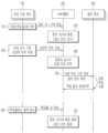
도 1 및 도 2를 참조하면, 본 발명의 실시예에 따른 공장내 위치 추적 시스템은, 공장내 절대 좌표를 가진 고정물(R1, R2, R3)에 배치된 복수의 마커(Marker, M), 생산 관리를 위한 추적 목표물(예; 차량)(10)에 고정 부착(장착)되며 카메라를 통해 촬영된 영상에서 시각적 위치 추정(Visual Odometry, VO) 방식으로 탐지된특정 마커(M)(이하에서는 참조 마커로 칭함)의 절대 위치를 인식하고 상기 참조 마커(M)의 절대 위치를 기준으로 상대적 위치를 추정하는 영상 수집 장비(100), 및 상기 영상 수집 장비(100)로부터 무선 통신으로 수신된 상기 상대적 위치를 기반으로 상기 목표물(10)의 위치를 추적하는 서버(200);를 포함한다. 여기서, 상기 상대적 위치는 공장내 좌표계상 한 점의 3D 좌표로서 영상 수집 장비(100)의 위치를 의미하고, 또한 영상 수집 장비(100)가 부착된 상기 목표물(10)의 위치를 의미할 수 있다.Referring to Figures 1 and 2, the factory position tracking system according to an embodiment of the present invention includes a plurality of markers (Marker, M) placed on fixtures (R1, R2, R3) with absolute coordinates in the factory, A specific marker (M) (hereinafter referred to as a reference marker) is fixedly attached (mounted) to a tracking target (e.g., a vehicle) (10) for management and detected using Visual Odometry (VO) in images captured by a camera.
영상 수집 장비(100)는 공장내 관리 대상 목표물(10)에 임시로 고정 부착(장착)된다(S10). 예컨대, 상기 목표물(10)은 컨베이어시스템을 따라 공정별로 이동하면서 조립되는 제품 차량, 상기 공정별로 필요한 부품을 공급하는 물류 로봇(예; Automated Guided Vehicle/Autonomous Mobile Robot, AGV/AMR), 상기 부품을 적재하는 이동 대차, 및 상기 공정별로 이동 가능한 공구 등일 수 있다.The
이하, 본 발명의 실시예를 설명함에 있어서, 상기 목표물(10)을 생산 제품인 "차량"으로 가정하여 설명하도록 하되, 상기 "차량"의 기재는 실질적인 "목표물"로 치환될 수 있다.Hereinafter, in describing an embodiment of the present invention, the target 10 will be described assuming that it is a “vehicle” that is a manufactured product, but the description of “vehicle” may be replaced with the actual “target.”
영상 수집 장비(100)는 자신의 장비 ID와 부착된 차량 식별정보(VIN)를 무선 통신을 통해 서버(200)로 전송한다.The
서버(200)는 영상 수집 장비(100)로부터 수신된 장비 ID와 VIN을 매칭하여 저장하고 해당 차량(10)에 대한 생산 관리를 개시한다(S20).The
도 1을 참조할 때, 차량 공장에 설치하여 운영중인 컨베이어시스템의 근방의 고정된 절대 좌표를 가진 구조물(R1, R2, R3)에 마커(M1, M2, M3, M4)들이 배치된다. 그리고, 컨베이어시스템의 생산 라인을 따라 작업자와 설비 장치(300)가 위치하여 해당 공정 작업을 수행한다. 상기 구조물(R1, R2, R3)은 공장내 기둥, 벽면 및 고정 표지판 등일 수 있다. 상기 마커(M1, M2, M3, M4)는 4개 코너점을 포함하는 4각형 테두리에 식별코드가 표시된 ArUco 마커로 구성되며, 상기 구조물(R)의 일면에 부착될 수 있다. 또한, 마커(M)는 일면에 여러 개가 부착될 수 있다. 본 발명의 실시예에 따른 마커(M)는 상기 ArUco 마커에 한정되지 않고 정사각형 테두리 내에 큐알(QR) 코드나 바코드를 확대하여 표시하는 방식으로 구현될 수도 있다.Referring to FIG. 1, markers (M1, M2, M3, M4) are placed on structures (R1, R2, R3) with fixed absolute coordinates near a conveyor system installed and operated in a vehicle factory. In addition, workers and
영상 수집 장비(100)는 개별 차량(10-1, 10-2, 10-3)에 부착된 상태로 컨베이어시스템을 따라 이동하면서 카메라부(110)를 통해 인식된 참조 마커(M)의 절대 위치(3D 좌표)에 대한 자신의 상대적 위치를 추정한다(S30). 여기서, 상기 절대 위치는 공장내 전체 좌표계(3D)에서 고정된 절대 좌표를 의미하며, 상기 상대적 위치는 상기 참조 마커(M)의 절대 좌표(x, y, z)와 그 방향(즉, 마커(M)가 향하는 방향; 이하 마커 방향이라 칭함)에 기준하여 공간적으로 일정 각도(θ)와 거리(D)에 떨어진 상대 좌표를 의미한다.The
가령, 도 1에서 제1 차량(10-1)의 영상 수집 장비(100)는 제1 마커(M1)의 절대 위치에 대한 상대적 위치를 추정하여 서버(200)로 전송한다. 마찬가지로 제2 차량(10-2) 및 제3 차량(10-3)의 영상 수집 장비(100)는 각각 제2 마커(M2) 및 제4 마커(M4)의 절대 위치에 대한 상대적 위치를 추정하여 서버(200)로 전송할 수 있다.For example, in FIG. 1, the
서버(200)는 영상 수집 장비(100)로부터 상대적 위치를 수신하면 이에 매칭된 차량(10)의 VIN을 확인하고 차량(10)의 실시간 위치를 추적 및 관리한다(S40).When the
그리고, 서버(200)는 상기 차량(10)의 차종/사양과 현재 위치를 기반으로 해당 공정별 설비 장치(300)를 파악하여 공정 작업 수행을 제어하고 그 작업 결과를 수신하여 업데이트 한다(S50).Then, the
이러한, 서버(200)는 공장내 차량(제품)의 생산과 설비 운용을 통합 관리 하는 생산 관리 시스템(Manufacturing Execution System, MES)으로 구현될 수 있다. 이러한, 서버(200)는 공장내 각 공정별로 이송되는 차량(10)의 위치 추적 기반의 생산 관리, 차량(10)의 차종/사양을 고려한 공정별 설비 장치(300)의 운용 관리, 및 물류 로봇을 이용한 공정별 부품 공급 관리 등의 공장내 제품 생산 스케줄과 설비 전반을 통합 관리할 수 있다.The
영상 수집 장비(100)는 차량(10)의 생산 관리를 위해 사용 후 생산을 완료한 완성 차량(10)으로부터의 탈착 정보를 서버(200)로 전송한다(S60). 이때에도 자신의 장비 ID와 탈착된 차량의 VIN을 무선 통신을 통해 서버(200)로 전송할 수 있다.The
이에, 서버(200)는 영상 수집 장비(100)로부터 상기 탈착 정보를 수신하면 장비 ID와 차량의 VIN의 매칭을 해제하고 해당 차량(10)에 대한 생산 관리를 종료한다(S70).Accordingly, when the
이처럼, 영상 수집 장비(100)는 공장내에서 관리 대상인 개별 차량(10)에 부착하여 사용 후 생산을 완료한 차량으로부터 회수되어 다른 차량에 재사용된다.In this way, the
한편, 도 3은 본 발명의 실시예에 따른 영상 수집 장비의 구성을 개략적으로 나타낸 블록도이다.Meanwhile, Figure 3 is a block diagram schematically showing the configuration of image collection equipment according to an embodiment of the present invention.
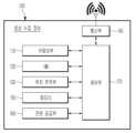
도 3을 참조하면, 본 발명의 실시예에 따른 영상 수집 장비(100)는 카메라부(110), IMU(120), 위치 추적부(130), 통신부(140), 메모리(150), 전원 공급부(160), 및 제어부(170)를 포함한다.Referring to FIG. 3, the
카메라부(110)는 적어도 하나의 카메라를 통해 목표물 차량(10)의 주변을 촬영한다. 카메라부(110)는 좌우 영상을 이용하여 3차원 공간 좌표(x, y, z)를 획득하는 스테레오 카메라를 포함할 수 있다.The
IMU(Inertial Measurement Unit)(120)는 각종 센서를 통해 차량(10)의 가속도와 이동 방향을 측정하며, 이를 통해 상기 가속도와 이동 방향을 포함하는 관성값을 도출한다.The IMU (Inertial Measurement Unit) 120 measures the acceleration and movement direction of the vehicle 10 through various sensors, and through this, derives an inertial value including the acceleration and movement direction.
위치 추적부(130)는 카메라부(110)를 통해 수집한 비디오 영상을 분석하여 실내에 고정된 참조 마커(M)의 절대 위치를 인식하고 상기 절대 위치로부터 자신(즉, 영상 수집 장비)의 상대적 위치를 추정하는 역할을 한다.The
위치 추적부(130)는 참조 마커(M)의 기하학적 형상에서 도출된 마커 코드를 기초로 메모리(150)에 조회하여 해당 참조 마커의 절대 위치 및 마커 방향을 인식할 수 있다. 여기서, 상기 절대 위치는 공장내 좌표계 상에 고정된 3D 좌표(즉, 설치 위치)를 의미하며 상기 마커 방향은 설치 위치에서 참조 마커(M)의 평면이 향하고 있는 방향을 의미한다. 상기 마커 방향은 추후에 참조 마커(M)의 절대 좌표를 기준으로 차량(10)이 어느 방향(방위)에 있는지 파악하기 위한 마커 좌표계(3D)의 기준이 된다. 상기 마커 좌표계에 대해서는 뒤에서 자세히 설명하도록 한다.The
위치 추적부(130)는 카메라부(110)에서 수신된 비디오 영상을 시각적 위치추적 알고리즘으로 분석하여 이미지 데이터를 획득한다. 예컨대, 위치 추적부(130)는 상기 비디오 영상을 분석하여 다수의 프레임(Frame)중 선명한 최적 화질의 이미지 데이터와 오리엔테이션(Orientation) 데이터를 추출할 수 있다. 상기 오리엔테이션 데이터는 카메라부(110)의 촬영 방향과 회전 정보 등을 포함한다.The
도 4는 본 발명의 실시예에 따른 상대적 위치 추정 과정을 구체적으로 설명하기 위한 이미지 데이터 처리 흐름을 나타낸다.Figure 4 shows an image data processing flow to specifically explain the relative position estimation process according to an embodiment of the present invention.
도 4를 참조하면, 본 발명의 실시예에 따른 상대적 위치 추정 과정은, 위치 추적부(130)가 카메라부(110)에서 획득한 이미지 데이터내 존재하는 참조 마커(M)를 검출하는 과정(A); 상기 참조 마커(M)의 기하학적 형상을 독출하여 사전에 정의된 마커 코드(ID)를 인식하는 과정(B); 및 상기 참조 마커(M)의 절대 위치로부터 상대적 위치를 추정하는 과정(C);을 포함한다.Referring to FIG. 4, the relative position estimation process according to an embodiment of the present invention is a process (A) in which the
먼저, 상기 참조 마커(M) 후보를 검출하는 과정(A)에 대해 구체적으로 설명한다.First, the process (A) of detecting the reference marker (M) candidate will be described in detail.
위치 추적부(130)는 상기 이미지 데이터에 대하여 영상 처리 기반의 특징 탐지(Feature detection)를 수행하여, 상기 이미지 데이터에 상기 참조 마커(M)가 존재하는지 판단한다.. 이 때, 위치 추적부(130)는 상기 이미지 데이터에 상기 참조 마커(M)가 존재하는 경우, 상기 이미지 데이터를 사전에 정의된 문턱값을 기준으로 이진화 처리하는 단계; 상기 이진화 처리한 이미지에서 정사각형 모양의 마커 후보를 탐지하는 단계; 및 복수의 마커 후보가 탐지되면 가장 크고 왜곡이 적은 마커 후보를 상기 참조 마커로 선정하는 단계를 수행할 수 있다.The
다음, 상기 마커 코드(ID)를 인식하는 과정(B)에 대해 구체적으로 설명한다.Next, the process (B) of recognizing the marker code (ID) will be described in detail.
위치 추적부(130)는 상기 유효 마커에 표시된 기하학적 형상을 추출 및 해석하여 해당 마커 코드(예; ID=40)와 상기 마커 코드에 상응하는 절대 좌표 및 마커 방향을 인식한다. 이 때, 상기 마커 코드 인식 과정은 상기 유효 마커(M)의 왜곡된 모양을 정사각형으로 복원하는 단계; 사전에 정의된 마커의 비트 수에 따라 등간격의 그리드를 형성하는 단계; 상기 그리드내 중앙값을 생성한후 백색 또는 흑색을 읽어 들여 참조 마커(M)에 표시된 기하학적 형상의 비트값을 추출하는 단계; 및 상기 비트값이 사전에 정의된 마커 사전에 존재하는지 메모리(150)에 조회하는 단계, 및 상기 비트값이 존재하면 인식된 마커 코드를 출력하는 단계를 포함한다. 다만, 상기 비트값이 존재하지 않으면 무효한 것으로 판단하고 배제(Rejection) 시킬 수 있다.The
다음, 상기 상대적 위치를 추정하는 과정(C)에 대해 구체적으로 설명한다.Next, the process (C) of estimating the relative position will be described in detail.
위치 추적부(130)는 상기 참조 마커(M)의 절대 좌표와 마커 방향을 기준으로 일정 각도(θ)와 거리(D)에 공간적으로 떨어진 상대적 위치(3D)를 추정하기 위한 마커 좌표계를 생성한다.The
상기 마커 좌표계를 생성하는 방법은, 상기 참조 마커(M)의 정사각형 테두리의 4개 꼭지점 좌표(예; (-L/2, L/2, 0), (L/2, L/2,0), (L/2,-L/2,0),(-L/2, -L/2,0))와 4개 변의 길이(L)을 파악하는 단계; 상기 참조 마커(M)의 정사각형 테두리를 이용하여 정사각형의 평면 중앙(예; 참조 마커의 절대 좌표)으로부터 수직 방향의 Z축과 직교하는 두 변과 동일하게 상기 평면 중앙에서 직교하는 X축 및 Y축을 가지는 마커 좌표계(x, y, z)를 생성하는 단계;를 포함한다.The method of generating the marker coordinate system is the coordinates of the four vertices of the square border of the reference marker (M) (e.g., (-L/2, L/2, 0), (L/2, L/2,0) , (L/2,-L/2,0),(-L/2, -L/2,0)) and determining the lengths (L) of the four sides; Using the square border of the reference marker (M), the It includes generating a marker coordinate system (x, y, z).
위와 같이, 위치 추적부(130)는 상기 이미지 데이터에 대한 특징 탐지를 지속적으로 수행하여 주변 환경의 이동을 파악하고 이를 통해 기존 좌표 대비 이동한 이동 거리와 이동 방향을 추정할 수 있다. 다만, 이러한 추정은 실제로 참조 마커(M)가 보이는 각도(θ)와 거리(D), 참조 마커 이미지의 크기 및 왜곡 정도 따라 오차가 존재할 수 있다.As described above, the
따라서, 위치 추적부(130)는 상기 오차를 보정하기 위하여 설정된 조건에 맞게 연속적이고 안정적으로 탐지된 참조 마커(M)의 추정 결과들을 저장하고 그 추정된 좌표들의 점들을 모아 점군의 전체적인 이동 방향을 고려하여 실제 추정위치와 이동 방향을 보정할 수 있다.Therefore, the
예컨대, 도 5는 본 발명의 실시예에 따른 참조 마커로부터 상대적 좌표를 인식한 결과를 나타낸다.For example, Figure 5 shows the results of recognizing relative coordinates from a reference marker according to an embodiment of the present invention.
도 5를 참조하면, 차량(10)의 이동상태에서 시계열로 수집된 복수의 이미지 데이터에서 참조 마커(M)가 연속적이고 안정적으로 탐지되는 동안에 추정된 상대적 좌표들(예; 13개)을 나타낸다. 여기서, 상기 참조 마커(M)가 연속적이고 안정적으로 탐지된다는 것은 다음 조건을 만족하는 연속된 경우를 의미한다.Referring to FIG. 5, relative coordinates (eg, 13) estimated while the reference marker M is continuously and stably detected in a plurality of image data collected in time series while the vehicle 10 is moving are shown. Here, that the reference marker (M) is continuously and stably detected means continuous cases that satisfy the following conditions.
위치 추적부(130)는 복수의 이미지 데이터를 동일한 방법으로 처리하여 참조 마커(M)를 탐지한 상태에서 연속적으로 탐지한 참조 마커(M)들의 마커 코드(ID)가 동일하며, 참조 마커(M)의 영역을 차지하는 픽셀 수가 특정값 이상이고, 상기 픽셀 수의 변화가 연속적으로 존재하는 조건들을 모두 만족하면 연속적이고 안정적으로 탐지되는 것으로 판단할 수 있다. 상기 픽셀 수의 변화는 차량(10)의 이동으로 카메라부(110)의 촬영 각도(θ1, θ2, θ3)가 변함에 따라 참조 마커(M)의 정사각형 모양이 왜곡되기 때문에 변화한다.The
상기 상대적 좌표들은 마커 좌표계를 기준으로 시야 각도(θ)와 거리(D)에 따라 추정 오차가 발생될 수 있으므로 퍼진 형태의 점군(분포)을 형성한다. 상기 점군을 형성하는 상대적 좌표들의 전체적인 이동 방향을 고려하여 실제 추정 위치와 이동 방향을 보정한다. 이를 위해 위치 추적부(130)는 주성분 분석(Principal Component Analysis, PCA)을 통해 제1 주성분 벡터를 바탕으로 주요 이동 방향을 추론할 수 있다. 또한, VO 알고리즘 상의 회전 방향을 보정하기 위해 제1 주성분 벡터에서 마커 좌표계의 x, y 성분만을 가져온 벡터와 기준 좌표(1,0,0)와의 각도차를 구하고 이를 이용하여 VO 알고리즘상의 회전행렬을 업데이트 한다. 이러한 방식은 통상의 VO 알고리즘을 활용할 수 있다.The relative coordinates form a spread point group (distribution) because estimation errors may occur depending on the viewing angle (θ) and distance (D) based on the marker coordinate system. The actual estimated position and movement direction are corrected by considering the overall movement direction of the relative coordinates forming the point group. To this end, the
한편, 위치 추적부(130)는 상기 이미지 데이터 내에 참조 마커(M)가 탐지되지 않으면 마지막으로 파악된 상대적 위치와 IMU(120)에서 도출된 관성값을 토대로 움직임 예측(Motion Estimation)을 수행하여 움직인 상대적 위치(3D)를 추정할 수 있다. 즉, 마지막으로 파악된 상대적 위치로부터 움직임 벡터를 예측하여 실시간으로 상기 참조 마커(M)에 대한 상대적 위치(3D)를 추정할 수 있다.Meanwhile, if the reference marker (M) is not detected in the image data, the
통신부(140)는 위치 추적부(130)에서 추정된 상대적 위치를 무선 통신을 통해 서버(200)로 전송한다. 상기 상대적 위치는 영상 수집 장비 ID, 인식된 마커 코드, 참조 마커(M)에 대한 상대 좌표(3D), 이동 방향, 이미지 데이터 및 오리엔테이션(Orientation) 데이터 중 적어도 하나를 포함하는 메시지 형태로 전송될 수 있다.The
메모리(150)는 영상 수집 장비(100)의 전반적인 운용을 위한 적어도 하나의 프로그램 및 데이터를 저장하며, 그 운용에 따라 생성되는 데이터를 저장한다.The
예컨대, 메모리(150)는 카메라부(110)에서 수집된 비디오 영상, 상기 비디오 영상을 처리한 이미지 데이터와 오리엔테이션(Orientation) 데이터를 저장한다.For example, the
또한, 메모리(150)는 3D 맵 기반의 공장내 공간 좌표계와 상기 좌표계 상에 배치된 참조 마커(M)들의 절대 좌표, 마커 좌표계, 마커 인식 프로그램, 마커 영상 처리 및 VO 알고리즘 등을 저장할 수 있다.Additionally, the
전원 공급부(160)는 외부 전원과 연결되는 케이블 커넥터와 충방전 가능한 이차전지 중 적어도 하나를 포함하며 영상 수집 장비(100)의 동작을 위한 전원을 공급한다.The
제어부(170)는 본 발명의 실시예에 따른 공장내 목표물의 위치 추적을 위한 프로그램을 실행하여 상기 각부의 전반적인 동작을 제어한다. 그러므로, 앞에서 설명한 상기 각부의 동작은 실질적으로 제어부(170)에 의해 동작하는 것으로 이해하여야 한다.The
이러한, 제어부(170)는 카메라부(110)로부터 획득한 이미지 데이터를 위치 추적부(130)를 통해 처리하여 고정물에 부착된 참조 마커(M)의 절대 위치를 인식하고, VO 알고리즘을 활용하여 상기 참조 마커(M)의 절대 위치로부터 차량(10)의 상대적 위치를 추정한다.The
그리고, 제어부(170)는 추정한 상대적 위치를 통신부(140)를 통해 서버(200)로 전송하여 생산공장내 관리 대상 목표물의 위치 추적을 지원한다.In addition, the
이러한 제어부(170)는 설정된 프로그램에 의하여 동작하는 하나 이상의 프로세서로 구현될 수 있으며, 상기 설정된 프로그램은 본 발명의 실시예에 따른 공장내 목표물의 위치 추적 방법의 각 단계를 수행하도록 프로그래밍 된 것일 수 있다.This
이러한 공장내 목표물의 위치 추적 방법은 아래의 도면을 참조하여 더욱 구체적으로 설명하기로 한다.This method of tracking the location of a target within a factory will be described in more detail with reference to the drawings below.
도 6은 본 발명의 실시예에 따른 공장내 목표물의 위치 추적 방법을 개략적으로 나타낸 흐름도이다.Figure 6 is a flowchart schematically showing a method for tracking the location of a target in a factory according to an embodiment of the present invention.
도 6을 참조하면, 앞서 설명한 도 2의 S30 단계에서, 영상 수집 장비(100)가 카메라부(110)를 통해 인식된 특정 참조 마커(M)의 절대 위치(3D 좌표)에 대한 자신의 상대적 위치를 추정하는 흐름을 구제적으로 보여준다.Referring to FIG. 6, in step S30 of FIG. 2 described above, the
영상 수집 장비(100)의 제어부(170)는 카메라부(110)를 통해 이동 중 촬영된 주변의 이미지 데이터를 수집한다(S110).The
제어부(170)는 IMU(120)를 통해 차량(10) 가속도와 이동 방향을 포함하는 관성값을 도출한다(S120).The
제어부(170)는 위치 추적부(130)를 통해 VO(Visual Odometry)기반 위치 추정 방식으로 상기 이미지 데이터에 참조 마커(M)가 존재하는지 탐지한다(S130).The
이 때, 상기 이미지 데이터내 존재하는 참조 마커(M)가 탐지되면(130; 예), 제어부(170)는 복수의 이미지 데이터에서 설정된 조건에 맞게 연속적이고 안정적으로 참조 마커(M)들이 탐지되는지 파악한다(S150).At this time, when the reference marker (M) present in the image data is detected (130; example), the
이 때, 상기 연속적이고 안정적으로 참조 마커(M)들이 탐지되면(S150; 예), 제어부(170)는 상기 참조 마커(M)를 독출하여 사전에 정의된 참조 마커(M)의 절대 위치와 마커 방향을 인식하고(S160), 상기 참조 마커(M)의 절대 위치와 마커 방향을 기반으로 자신의 상대적 위치를 추정한다(S170).At this time, when the reference markers (M) are continuously and stably detected (S150; example), the
제어부(170)는 차량(10)의 상대적 위치 정보를 무선 통신으로 연결된 서버(200)로 전송하여 차량의 추적 위치를 업데이트 하도록 한다(S180). 이 때, 전송되는 상기 상대적 위치 정보는 해당 영상 수집 장비 ID, 마커 코드, 마커 기준 상대 좌표(3D), 이동 방향, 이미지 데이터 및 오리엔테이션(Orientation) 데이터 중 적어도 하나를 포함할 수 있다.The
한편, 상기 130 단계에서, 상기 이미지 데이터내 존재하는 참조 마커(M)가 탐지되지 않으면(130; 아니오), 제어부(170)는 마지막으로 파악된 상대적 위치와 IMU(120)를 통해 도출된 관성값을 토대로 움직임 예측(Motion Estimation)을 수행하여 현재 상대적 위치(3D)를 추정할 수 있다.Meanwhile, in
또한, 상기 150 단계에서, 제어부(170)는 상기 연속적이고 안정적으로 참조 마커(M)들이 탐지 되지 않으면(S150; 아니오), 해당 참조 마커(M)를 무효한 것으로 판단하여 분석 대상에서 배제시키고 상기 S110 단계로 돌아간다.In addition, in
이와 같이, 본 발명의 실시예에 따르면, 공장내 추적 목표물에 부착된 영상 수집 장비를 통해 고정물에 배치된 참조 마커를 인식하고 참조 마커의 절대 위치로부터 상대적 위치를 측정하는 개선된 위치 추적 시스템을 제공함으로써 종래의 위치 추적 방식에 사용하던 AP를 삭제할 수 있고 그에 따른 투자 비용 및 유지보수 비용을 절감할 수 있다.As such, according to an embodiment of the present invention, an improved position tracking system is provided that recognizes a reference marker placed on a fixture through an image collection device attached to a tracking target in a factory and measures the relative position from the absolute position of the reference marker. By doing so, the AP used in the conventional location tracking method can be deleted and the resulting investment and maintenance costs can be reduced.
또한, 공장내 고정좌표 영역인 고정물에 다양한 방향으로 인쇄물 형태의 마커들을 자유롭고 간단하게 배치할 수 있어 마커들의 배치 밀도 향상에 따라 목표물의 위치 추적 정확도를 향상시킬 수 있다.In addition, markers in the form of prints can be freely and simply placed in various directions on the fixture, which is a fixed coordinate area in the factory, and the accuracy of target location tracking can be improved by improving the placement density of the markers.
또한, 종래의 위치 추적 방식에 사용하던 AP의 삭제에 따른 무선 신호의 멀티패스 문제를 제거하고 AP의 설치 위치 또한 고려할 필요가 없어 공장의 라인 구성 및 설계에 작업을 용이하게 하는 효과가 있다.In addition, it eliminates the multipath problem of wireless signals caused by the deletion of the AP used in the conventional location tracking method, and there is no need to consider the installation location of the AP, which has the effect of making work easier in factory line configuration and design.
본 발명의 실시예는 이상에서 설명한 장치 및/또는 방법을 통해서만 구현이 되는 것은 아니며, 본 발명의 실시예의 구성에 대응하는 기능을 실현하기 위한 프로그램, 그 프로그램이 기록된 기록 매체 등을 통해 구현될 수도 있으며, 이러한 구현은 앞서 설명한 실시예의 기재로부터 본 발명이 속하는 기술분야의 전문가라면 쉽게 구현할 수 있는 것이다.The embodiments of the present invention are not implemented only through the devices and/or methods described above, but can be implemented through programs for realizing functions corresponding to the configuration of the embodiments of the present invention, recording media on which the programs are recorded, etc. This implementation can be easily implemented by an expert in the technical field to which the present invention belongs based on the description of the embodiments described above.
이상에서 본 발명의 실시예에 대하여 상세하게 설명하였지만 본 발명의 권리범위는 이에 한정되는 것은 아니고 다음의 청구범위에서 정의하고 있는 본 발명의 기본 개념을 이용한 당업자의 여러 변형 및 개량 형태 또한 본 발명의 권리범위에 속하는 것이다.Although the embodiments of the present invention have been described in detail above, the scope of the present invention is not limited thereto, and various modifications and improvements made by those skilled in the art using the basic concept of the present invention defined in the following claims are also possible. It falls within the scope of rights.
R: 고정물 M: 마커
10: 목표물(차량)
100: 영상 수집 장비 110: 카메라부
120: IMU 130: 위치 추적부
140: 통신부 150: 메모리
160: 전원 공급부 170: 제어부
200: 서버 300: 설비 장치R: Fixture M: Marker
10: Target (vehicle)
100: video collection equipment 110: camera unit
120: IMU 130: Location tracking unit
140: Communication unit 150: Memory
160: power supply unit 170: control unit
200: server 300: equipment device
Claims (19)
Translated fromKorean관리를 위한 추적 목표물에 고정 부착되며 카메라를 통해 촬영된 영상에서 시각적 위치 추정(Visual Odometry, VO) 방식으로 탐지된 참조 마커(M)의 절대 위치를 인식하고 상기 참조 마커(M)의 절대 위치를 기준으로 상대적 위치(3D)를 추정하는 영상 수집 장비; 및
상기 영상 수집 장비로부터 무선 통신으로 수신된 상기 상대적 위치를 기반으로 상기 목표물의 위치를 추적하는 서버;
를 포함하는 공장내 위치 추적 시스템.A plurality of markers (M) placed on fixtures in an area with absolute coordinates within the factory;
It is fixedly attached to a tracking target for management and recognizes the absolute position of the reference marker (M) detected through visual odometry (VO) in the image captured by the camera and determines the absolute position of the reference marker (M). Image acquisition equipment that estimates relative position (3D) as a reference; and
a server that tracks the location of the target based on the relative location received through wireless communication from the image collection equipment;
In-factory location tracking system including.
상기 영상 수집 장비는,
적어도 하나의 카메라를 통해 상기 목표물의 주변을 촬영하는 카메라부;
상기 목표물의 가속도와 이동 방향을 포함하는 관성값을 도출하는 IMU(Inertial Measurement Unit);
상기 카메라부를 통해 수집한 비디오 영상을 분석하여 실내에 고정된 상기 참조 마커(M)의 절대 위치를 인식하고 상기 절대 위치로부터 상대적 위치를 추정하는 위치 추적부;
상기 상대적 위치를 무선 통신을 통해 상기 서버로 전송하는 통신부;
상기 영상 수집 장비의 운용을 위한 적어도 하나의 프로그램 및 데이터를 저장하는 메모리;
케이블 커넥터와 충방전 가능한 이차전지 중 적어도 하나를 포함하는 전원 공급부; 및
상기 목표물의 위치 추적을 위한 프로그램을 실행하여 각부의 전반적인 동작을 제어하는 제어부;
를 포함하는 공장내 위치 추적 시스템.According to paragraph 1,
The image collection equipment is,
a camera unit that photographs the surroundings of the target through at least one camera;
An IMU (Inertial Measurement Unit) that derives an inertial value including the acceleration and direction of movement of the target;
a position tracking unit that analyzes the video image collected through the camera unit to recognize the absolute position of the reference marker (M) fixed indoors and estimates the relative position from the absolute position;
a communication unit transmitting the relative location to the server through wireless communication;
a memory storing at least one program and data for operating the image collection equipment;
A power supply unit including at least one of a cable connector and a rechargeable secondary battery; and
a control unit that executes a program for tracking the location of the target and controls the overall operation of each part;
In-factory location tracking system including.
상기 위치 추적부는,
상기 참조 마커(M)의 기하학적 형상에서 도출된 마커 코드를 기초로 메모리에 조회하여 해당 공장내 좌표계 상에 고정된 절대 위치 및 상기 참조 마커(M)의 평면이 향하고 있는 마커 방향을 인식하는 공장내 위치 추적 시스템.According to paragraph 2,
The location tracking unit,
Based on the marker code derived from the geometric shape of the reference marker (M), the memory is searched to recognize the absolute position fixed on the coordinate system within the factory and the marker direction toward which the plane of the reference marker (M) is facing. Location tracking system.
상기 위치 추적부는,
상기 참조 마커(M)의 절대 좌표와 마커 방향을 기준으로 일정 각도(θ)와 거리(D)에 공간적으로 떨어진 상기 상대적 위치를 추정하는 공장내 위치 추적 시스템.According to paragraph 3,
The location tracking unit,
An in-factory location tracking system that estimates the relative position spatially separated by a certain angle (θ) and distance (D) based on the absolute coordinates and marker direction of the reference marker (M).
상기 위치 추적부는,
상기 비디오 영상을 분석하여 다수의 프레임(Frame)중 선명한 화질의 이미지 데이터와 오리엔테이션(Orientation) 데이터를 추출하는 공장내 위치 추적 시스템.According to paragraph 3,
The location tracking unit,
An in-factory location tracking system that analyzes the video image and extracts clear image data and orientation data from multiple frames.
상기 영상 수집 장비가 상기 상대적 위치를 추정하는 과정은,
상기 비디오 영상에서 추출된 이미지 데이터에 대한 영상 처리 기반의 특징 탐지(Feature detection)를 수행하여 상기 이미지 데이터 내에 존재하는 상기 참조 마커(M)를 검출하는 과정;
상기 참조 마커(M)의 기하학적 형상을 독출하여 사전에 정의된 마커 코드(ID)를 인식하는 과정; 및
상기 참조 마커(M)의 절대 위치로부터의 상기 추적 목표물의 상대적 위치를 추정하는 과정;
을 포함하는 공장내 위치 추적 시스템.According to any one of claims 1 to 5,
The process by which the image collection equipment estimates the relative position is,
A process of detecting the reference marker (M) present in the image data by performing image processing-based feature detection on the image data extracted from the video image;
A process of reading the geometric shape of the reference marker (M) and recognizing a predefined marker code (ID); and
A process of estimating the relative position of the tracking target from the absolute position of the reference marker (M);
In-factory location tracking system including.
상기 영상 수집 장비가 상기 참조 마커(M)를 검출하는 과정은,
상기 이미지 데이터에 대하여 영상 처리 기반의 특징 탐지(Feature detection)를 수행하여, 상기 이미지 데이터에 상기 참조 마커가 존재하는지 판단하는 단계;
상기 이미지 데이터에 상기 참조 마커가 존재하는 경우, 상기 이미지 데이터를 사전에 정의된 문턱값을 기준으로 이진화 처리하는 단계;
상기 이진화 처리한 이미지에서 정사각형 모양의 마커 후보를 탐지하는 단계; 및
복수의 마커 후보가 탐지되면, 상기 복수의 마커 후보들 중 가장 크고 왜곡이 적은 마커 후보를 상기 참조 마커로 선정하는 단계;
를 포함하는 공장내 위치 추적 시스템.According to clause 6,
The process by which the image collection equipment detects the reference marker (M) is,
Performing image processing-based feature detection on the image data to determine whether the reference marker exists in the image data;
If the reference marker is present in the image data, binarizing the image data based on a predefined threshold;
Detecting square-shaped marker candidates in the binarized image; and
When a plurality of marker candidates are detected, selecting the largest and least distorted marker candidate among the plurality of marker candidates as the reference marker;
In-factory location tracking system including.
상기 영상 수집 장비가 상기 마커 코드(ID)를 인식하는 과정은,
상기 참조 마커(M)의 왜곡된 모양을 정사각형으로 복원하는 단계;
사전에 정의된 마커의 비트 수에 따라 등간격의 그리드를 형성하는 단계;
상기 그리드 내 중앙값을 생성한후 백색 또는 흑색을 읽어 들여 상기 참조 마커(M)에 표시된 기하학적 형상의 비트값을 추출하는 단계;
상기 비트값이 사전에 정의된 마커 사전에 존재하는지 상기 메모리에 조회하는 단계; 및
상기 비트값이 존재하면 인식된 마커 코드를 출력하거나 상기 비트값이 존재하지 않으면 무효한 것으로 판단하고 배제시키는 단계;
를 포함하는 공장내 위치 추적 시스템.According to clause 6,
The process of the image collection equipment recognizing the marker code (ID) is,
Restoring the distorted shape of the reference marker (M) to a square;
forming an equally spaced grid according to the number of bits of a predefined marker;
generating a median within the grid and then extracting a bit value of the geometric shape displayed on the reference marker (M) by reading white or black;
querying the memory whether the bit value exists in a predefined marker dictionary; and
outputting a recognized marker code if the bit value exists, or determining it as invalid and excluding it if the bit value does not exist;
In-factory location tracking system including.
상기 영상 수집 장비가 상기 상대적 위치를 추정하는 과정은,
상기 참조 마커(M)의 절대 좌표와 마커 방향을 기준으로 상기 상대적 위치를 추정하기 위한 마커 좌표계를 생성하되,
상기 마커 좌표계를 생성하는 방법은, 상기 참조 마커의 정사각형 테두리의 4개 꼭지점 좌표와 4개 변의 길이를 파악하는 단계; 및
상기 참조 마커(M)의 정사각형 테두리를 이용하여 정사각형의 평면 중앙의 절대 좌표로부터 수직 방향의 Z축과 직교하는 두 변과 동일하게 상기 평면 중앙에서 직교하는 X축 및 Y축을 가지는 마커 좌표계(x, y, z)를 생성하는 단계;
를 포함하는 공장내 위치 추적 시스템.According to clause 6,
The process by which the image collection equipment estimates the relative position is,
Create a marker coordinate system to estimate the relative position based on the absolute coordinates and marker direction of the reference marker (M),
The method of generating the marker coordinate system includes determining the coordinates of four vertices and the lengths of four sides of a square border of the reference marker; and
Using the square border of the reference marker (M), a marker coordinate system (x, generating y, z);
In-factory location tracking system including.
상기 영상 수집 장비는,
상기 참조 마커의 크기 및 왜곡 정도로 인해 발생되는 오차를 보정하기 위하여 설정된 조건에 맞게 연속적이고 안정적인 상기 참조 마커(M)의 추정 결과들을 저장하고, 저장된 좌표들의 점들을 모은 점군의 이동 방향을 고려하여 실제 추정위치와 이동 방향을 보정하는 공장내 위치 추적 시스템.According to clause 6,
The image collection equipment is,
In order to correct errors caused by the size and degree of distortion of the reference marker, continuous and stable estimation results of the reference marker (M) are stored in accordance with set conditions, and the actual results are taken into account by considering the movement direction of the point cloud that collects the points of the stored coordinates. An in-factory location tracking system that corrects the estimated location and direction of movement.
상기 영상 수집 장비는,
상기 영상에 마커(M)가 탐지되지 않으면 마지막으로 파악된 상대적 위치와 상기 IMU에서 도출된 관성값을 토대로 움직임 예측(Motion Estimation)을 수행하여 현재 상대적 위치를 추정하는 공장내 위치 추적 시스템.According to paragraph 2,
The image collection equipment is,
An in-factory position tracking system that estimates the current relative position by performing motion estimation based on the last known relative position and the inertial value derived from the IMU when the marker (M) is not detected in the image.
상기 목표물은,
컨베이어시스템을 따라 공정별로 이동하면서 조립되는 차량, 상기 공정별로 필요한 부품을 공급하는 물류 로봇, 상기 부품을 적재하는 이동 대차, 및 상기 공정별로 이동 가능한 공구 중 적어도 하나를 포함하는 공장내 위치 추적 시스템.According to paragraph 1,
The target is,
An in-factory location tracking system including at least one of a vehicle that is assembled while moving for each process along a conveyor system, a logistics robot that supplies parts required for each process, a mobile cart that loads the parts, and a tool that can move for each process.
상기 서버는,
상기 차량의 차종 및 사양과 추적된 위치를 기반으로 해당 공정별 설비 장치를 파악하여 공정 작업 수행을 제어하고, 작업 결과를 수신하여 업데이트 하는 공장내 위치 추적 시스템.According to clause 12,
The server is,
An in-factory location tracking system that controls process work by identifying equipment for each process based on the vehicle model and specifications and tracked location, and receives and updates work results.
카메라부를 통해 이동중 촬영된 주변의 이미지 데이터를 수집하는 단계;
IMU(Inertial Measurement Unit)를 통해 가속도와 이동 방향을 측정하여 관성값을 도출하는 단계;
위치 추적부를 통해 상기 이미지 데이터에 공장내 절대 좌표를 가진 영역의 고정물에 배치된 참조 마커(M)가 존재하는지 탐지하는 단계; 및
상기 참조 마커(M)가 탐지되면 상기 참조 마커(M)의 기하학적 형상을 독출하여 사전에 정의된 상기 참조 마커(M)의 절대 위치와 마커 방향을 인식하고, 상기 참조 마커(M)의 절대 위치와 마커 방향을 기반으로 상기 추적 목표물의 상대적 위치를 추정하는 단계;
를 포함하는 공장내 위치 추적 방법.In the factory location tracking method of image collection equipment fixed to a tracking target for management,
Collecting surrounding image data captured while moving through a camera unit;
Deriving an inertia value by measuring acceleration and direction of movement using an IMU (Inertial Measurement Unit);
Detecting whether a reference marker (M) placed on a fixture in an area with absolute coordinates within the factory exists in the image data through a position tracking unit; and
When the reference marker (M) is detected, the geometric shape of the reference marker (M) is read, the predefined absolute position and marker direction of the reference marker (M) are recognized, and the absolute position of the reference marker (M) is recognized. and estimating the relative position of the tracking target based on the marker direction;
In-factory location tracking method including.
상기 참조 마커(M)가 존재하는지 탐지하는 단계는,
복수의 이미지 데이터에서 설정된 조건에 맞게 연속적이고 안정적으로 상기 참조 마커(M)들이 탐지되는지 파악하는 단계; 및
상기 연속적이고 안정적으로 탐지되지 않은 참조 마커(M)를 무효한 것으로 판단하여 분석 대상에서 배제시키는 단계;
를 포함하는 공장내 위치 추적 방법.According to clause 14,
The step of detecting whether the reference marker (M) exists is,
Determining whether the reference markers (M) are continuously and stably detected in a plurality of image data according to set conditions; and
determining the reference marker (M) that is not continuously and stably detected as invalid and excluding it from the analysis target;
A location tracking method within a factory including.
상기 설정된 조건은,
상기 복수의 이미지 데이터를 동일한 방법으로 처리하여 참조 마커(M)를 탐지한 상태에서 연속적으로 탐지된 참조 마커(M)들의 마커 코드가 동일하며,
상기 참조 마커(M)의 영역을 차지하는 픽셀 수가 특정값 이상이고,
상기 픽셀 수의 변화가 연속적으로 존재하는 조건들을 모두 만족하면,
상기 연속적이고 안정적으로 탐지된 것으로 판단하는 조건인 것을 특징으로 하는 공장내 위치 추적 방법.According to clause 15,
The conditions set above are,
When a reference marker (M) is detected by processing the plurality of image data in the same way, the marker codes of the reference markers (M) detected continuously are the same,
The number of pixels occupying the area of the reference marker (M) is greater than or equal to a certain value,
If all conditions for continuous change in the number of pixels are satisfied,
A location tracking method in a factory, characterized in that the condition is determined to be continuously and stably detected.
상기 참조 마커(M)가 존재하는지 탐지하는 단계 이후에,
상기 이미지 데이터내 존재하는 참조 마커(M)가 탐지되지 않으면 마지막으로 파악된 상대적 위치와 상기 관성값을 토대로 움직임 예측(Motion Estimation)을 수행하여 현재 상대적 위치를 추정하는 단계를 더 포함하는 공장내 위치 추적 방법.According to clause 14,
After detecting whether the reference marker (M) exists,
If the reference marker (M) present in the image data is not detected, the location within the factory further includes the step of performing motion estimation based on the last known relative position and the inertia value to estimate the current relative position. Tracking method.
상기 상대적 위치를 추정하는 단계 이후에,
상기 목표물의 상대적 위치 정보를 서버로 전송하여 상기 목표물의 추적 위치를 업데이트 하도록 하는 단계를 더 포함하는 공장내 위치 추적 방법.According to clause 14,
After estimating the relative position,
A location tracking method in a factory further comprising transmitting relative location information of the target to a server to update the tracking location of the target.
상기 상대적 위치 정보는,
해당 영상 수집 장비 ID, 마커 코드, 마커 기준 상대 좌표(3D), 이동 방향, 이미지 데이터 및 오리엔테이션(Orientation) 데이터 중 적어도 하나를 포함하는 공장내 위치 추적 방법.According to clause 18,
The relative location information is,
A method of tracking location in a factory that includes at least one of the relevant image collection equipment ID, marker code, marker-based relative coordinates (3D), movement direction, image data, and orientation data.
Priority Applications (3)
| Application Number | Priority Date | Filing Date | Title |
|---|---|---|---|
| KR1020220082374AKR20240005367A (en) | 2022-07-05 | 2022-07-05 | Location tracking system in factory and method |
| US18/345,691US20240012394A1 (en) | 2022-07-05 | 2023-06-30 | Location tracking system in factory and method thereof |
| CN202310812726.4ACN117348537A (en) | 2022-07-05 | 2023-07-04 | Location tracking system and method in factory |
Applications Claiming Priority (1)
| Application Number | Priority Date | Filing Date | Title |
|---|---|---|---|
| KR1020220082374AKR20240005367A (en) | 2022-07-05 | 2022-07-05 | Location tracking system in factory and method |
Publications (1)
| Publication Number | Publication Date |
|---|---|
| KR20240005367Atrue KR20240005367A (en) | 2024-01-12 |
Family
ID=89362020
Family Applications (1)
| Application Number | Title | Priority Date | Filing Date |
|---|---|---|---|
| KR1020220082374APendingKR20240005367A (en) | 2022-07-05 | 2022-07-05 | Location tracking system in factory and method |
Country Status (3)
| Country | Link |
|---|---|
| US (1) | US20240012394A1 (en) |
| KR (1) | KR20240005367A (en) |
| CN (1) | CN117348537A (en) |
Cited By (1)
| Publication number | Priority date | Publication date | Assignee | Title |
|---|---|---|---|---|
| CN118392159A (en)* | 2024-06-26 | 2024-07-26 | 天津渤海职业技术学院 | Indoor navigation method and system for AGV robot |
Families Citing this family (3)
| Publication number | Priority date | Publication date | Assignee | Title |
|---|---|---|---|---|
| JP2023027471A (en)* | 2021-08-17 | 2023-03-02 | トヨタ自動車株式会社 | Walking support system |
| JP7630474B2 (en)* | 2022-10-20 | 2025-02-17 | 三菱ロジスネクスト株式会社 | Position estimation device, forklift, position estimation method and program |
| JP2025038999A (en)* | 2023-09-08 | 2025-03-21 | トヨタ自動車株式会社 | State switching device, moving body, and method for manufacturing moving body |
- 2022
- 2022-07-05KRKR1020220082374Apatent/KR20240005367A/enactivePending
- 2023
- 2023-06-30USUS18/345,691patent/US20240012394A1/enactivePending
- 2023-07-04CNCN202310812726.4Apatent/CN117348537A/enactivePending
Cited By (1)
| Publication number | Priority date | Publication date | Assignee | Title |
|---|---|---|---|---|
| CN118392159A (en)* | 2024-06-26 | 2024-07-26 | 天津渤海职业技术学院 | Indoor navigation method and system for AGV robot |
Also Published As
| Publication number | Publication date |
|---|---|
| CN117348537A (en) | 2024-01-05 |
| US20240012394A1 (en) | 2024-01-11 |
Similar Documents
| Publication | Publication Date | Title |
|---|---|---|
| KR20240005367A (en) | Location tracking system in factory and method | |
| US20230236280A1 (en) | Method and system for positioning indoor autonomous mobile robot | |
| US12147243B2 (en) | Autonomous robotic navigation in storage site | |
| CN108388244A (en) | Mobile-robot system, parking scheme based on artificial landmark and storage medium | |
| KR20180067523A (en) | Use object observations of mobile robots to generate spatiotemporal object inventory, and use inventory to determine monitoring parameters for mobile robots | |
| CN110134117B (en) | Mobile robot repositioning method, mobile robot and electronic equipment | |
| US8111876B2 (en) | Object position estimating system, object position estimating apparatus, object position estimating method, and object position estimating program | |
| JP2021512297A (en) | Visual navigation method and system with multiple equipment in variable scenes | |
| CN112621765B (en) | Automatic equipment assembly control method and device based on manipulator | |
| CN111832760A (en) | Automatic inspection method for well lid based on visual algorithm | |
| CN118752498A (en) | Autonomous navigation method and system for a steel bar tying robot | |
| JP2024542034A (en) | Thin object detection and avoidance in flying robots | |
| CN118999577A (en) | Pose estimation method, pose estimation device, robot and storage medium | |
| CN118565457A (en) | Grid map construction method and device based on observation direction and intelligent mobile device | |
| CN109389677B (en) | Real-time building method, system, device and storage medium of house three-dimensional live-action map | |
| CN116766191A (en) | Robot motion control method, device, computing device and storage medium | |
| Heredia et al. | Fast and robust feature matching for rgb-d based localization | |
| CN115661386A (en) | Environment map optimization method and device, robot and readable storage medium | |
| KR20230051895A (en) | Learning data collection system and method | |
| US20240045439A1 (en) | Task execution system, task execution method, and task execution program | |
| US20250014217A1 (en) | Camera location estimation apparatus, method and storage medium | |
| CN119197546B (en) | AGV multi-vehicle intelligent collaborative operation method, system and medium based on the Internet of Things | |
| CN119494947A (en) | An adaptive positioning method and system for smart factories | |
| Baek et al. | Efficient Parking Lot Management System and Aberrant Behavior Detection Only Using | |
| CN118505800A (en) | Grid map construction method and device and intelligent mobile device |
Legal Events
| Date | Code | Title | Description |
|---|---|---|---|
| PA0109 | Patent application | Patent event code:PA01091R01D Comment text:Patent Application Patent event date:20220705 | |
| PG1501 | Laying open of application | ||
| A201 | Request for examination | ||
| PA0201 | Request for examination | Patent event code:PA02012R01D Patent event date:20250521 Comment text:Request for Examination of Application |