KR20240002833A - Transport vehicle for transporting article in manufacturing factory and article transport system including the same - Google Patents
Transport vehicle for transporting article in manufacturing factory and article transport system including the sameDownload PDFInfo
- Publication number
- KR20240002833A KR20240002833AKR1020220080920AKR20220080920AKR20240002833AKR 20240002833 AKR20240002833 AKR 20240002833AKR 1020220080920 AKR1020220080920 AKR 1020220080920AKR 20220080920 AKR20220080920 AKR 20220080920AKR 20240002833 AKR20240002833 AKR 20240002833A
- Authority
- KR
- South Korea
- Prior art keywords
- frame
- unit
- transport
- bumper
- traveling
- Prior art date
- Legal status (The legal status is an assumption and is not a legal conclusion. Google has not performed a legal analysis and makes no representation as to the accuracy of the status listed.)
- Ceased
Links
Images


Classifications
- B—PERFORMING OPERATIONS; TRANSPORTING
- B65—CONVEYING; PACKING; STORING; HANDLING THIN OR FILAMENTARY MATERIAL
- B65G—TRANSPORT OR STORAGE DEVICES, e.g. CONVEYORS FOR LOADING OR TIPPING, SHOP CONVEYOR SYSTEMS OR PNEUMATIC TUBE CONVEYORS
- B65G35/00—Mechanical conveyors not otherwise provided for
- H—ELECTRICITY
- H01—ELECTRIC ELEMENTS
- H01L—SEMICONDUCTOR DEVICES NOT COVERED BY CLASS H10
- H01L21/00—Processes or apparatus adapted for the manufacture or treatment of semiconductor or solid state devices or of parts thereof
- H01L21/67—Apparatus specially adapted for handling semiconductor or electric solid state devices during manufacture or treatment thereof; Apparatus specially adapted for handling wafers during manufacture or treatment of semiconductor or electric solid state devices or components ; Apparatus not specifically provided for elsewhere
- H01L21/677—Apparatus specially adapted for handling semiconductor or electric solid state devices during manufacture or treatment thereof; Apparatus specially adapted for handling wafers during manufacture or treatment of semiconductor or electric solid state devices or components ; Apparatus not specifically provided for elsewhere for conveying, e.g. between different workstations
- H01L21/67703—Apparatus specially adapted for handling semiconductor or electric solid state devices during manufacture or treatment thereof; Apparatus specially adapted for handling wafers during manufacture or treatment of semiconductor or electric solid state devices or components ; Apparatus not specifically provided for elsewhere for conveying, e.g. between different workstations between different workstations
- H01L21/67724—Apparatus specially adapted for handling semiconductor or electric solid state devices during manufacture or treatment thereof; Apparatus specially adapted for handling wafers during manufacture or treatment of semiconductor or electric solid state devices or components ; Apparatus not specifically provided for elsewhere for conveying, e.g. between different workstations between different workstations by means of a cart or a vehicule
- H—ELECTRICITY
- H01—ELECTRIC ELEMENTS
- H01L—SEMICONDUCTOR DEVICES NOT COVERED BY CLASS H10
- H01L21/00—Processes or apparatus adapted for the manufacture or treatment of semiconductor or solid state devices or of parts thereof
- H01L21/67—Apparatus specially adapted for handling semiconductor or electric solid state devices during manufacture or treatment thereof; Apparatus specially adapted for handling wafers during manufacture or treatment of semiconductor or electric solid state devices or components ; Apparatus not specifically provided for elsewhere
- H01L21/677—Apparatus specially adapted for handling semiconductor or electric solid state devices during manufacture or treatment thereof; Apparatus specially adapted for handling wafers during manufacture or treatment of semiconductor or electric solid state devices or components ; Apparatus not specifically provided for elsewhere for conveying, e.g. between different workstations
- H01L21/67703—Apparatus specially adapted for handling semiconductor or electric solid state devices during manufacture or treatment thereof; Apparatus specially adapted for handling wafers during manufacture or treatment of semiconductor or electric solid state devices or components ; Apparatus not specifically provided for elsewhere for conveying, e.g. between different workstations between different workstations
- H01L21/67733—Overhead conveying
- B—PERFORMING OPERATIONS; TRANSPORTING
- B65—CONVEYING; PACKING; STORING; HANDLING THIN OR FILAMENTARY MATERIAL
- B65G—TRANSPORT OR STORAGE DEVICES, e.g. CONVEYORS FOR LOADING OR TIPPING, SHOP CONVEYOR SYSTEMS OR PNEUMATIC TUBE CONVEYORS
- B65G43/00—Control devices, e.g. for safety, warning or fault-correcting
- B65G43/08—Control devices operated by article or material being fed, conveyed or discharged
- B—PERFORMING OPERATIONS; TRANSPORTING
- B66—HOISTING; LIFTING; HAULING
- B66C—CRANES; LOAD-ENGAGING ELEMENTS OR DEVICES FOR CRANES, CAPSTANS, WINCHES, OR TACKLES
- B66C11/00—Trolleys or crabs, e.g. operating above runways
- B—PERFORMING OPERATIONS; TRANSPORTING
- B66—HOISTING; LIFTING; HAULING
- B66C—CRANES; LOAD-ENGAGING ELEMENTS OR DEVICES FOR CRANES, CAPSTANS, WINCHES, OR TACKLES
- B66C19/00—Cranes comprising trolleys or crabs running on fixed or movable bridges or gantries
- H—ELECTRICITY
- H01—ELECTRIC ELEMENTS
- H01L—SEMICONDUCTOR DEVICES NOT COVERED BY CLASS H10
- H01L21/00—Processes or apparatus adapted for the manufacture or treatment of semiconductor or solid state devices or of parts thereof
- H01L21/67—Apparatus specially adapted for handling semiconductor or electric solid state devices during manufacture or treatment thereof; Apparatus specially adapted for handling wafers during manufacture or treatment of semiconductor or electric solid state devices or components ; Apparatus not specifically provided for elsewhere
- H01L21/67005—Apparatus not specifically provided for elsewhere
- H01L21/67242—Apparatus for monitoring, sorting or marking
- H01L21/67259—Position monitoring, e.g. misposition detection or presence detection
- H—ELECTRICITY
- H01—ELECTRIC ELEMENTS
- H01L—SEMICONDUCTOR DEVICES NOT COVERED BY CLASS H10
- H01L21/00—Processes or apparatus adapted for the manufacture or treatment of semiconductor or solid state devices or of parts thereof
- H01L21/67—Apparatus specially adapted for handling semiconductor or electric solid state devices during manufacture or treatment thereof; Apparatus specially adapted for handling wafers during manufacture or treatment of semiconductor or electric solid state devices or components ; Apparatus not specifically provided for elsewhere
- H01L21/677—Apparatus specially adapted for handling semiconductor or electric solid state devices during manufacture or treatment thereof; Apparatus specially adapted for handling wafers during manufacture or treatment of semiconductor or electric solid state devices or components ; Apparatus not specifically provided for elsewhere for conveying, e.g. between different workstations
- H01L21/67703—Apparatus specially adapted for handling semiconductor or electric solid state devices during manufacture or treatment thereof; Apparatus specially adapted for handling wafers during manufacture or treatment of semiconductor or electric solid state devices or components ; Apparatus not specifically provided for elsewhere for conveying, e.g. between different workstations between different workstations
- H01L21/67706—Mechanical details, e.g. roller, belt
- H—ELECTRICITY
- H01—ELECTRIC ELEMENTS
- H01L—SEMICONDUCTOR DEVICES NOT COVERED BY CLASS H10
- H01L21/00—Processes or apparatus adapted for the manufacture or treatment of semiconductor or solid state devices or of parts thereof
- H01L21/67—Apparatus specially adapted for handling semiconductor or electric solid state devices during manufacture or treatment thereof; Apparatus specially adapted for handling wafers during manufacture or treatment of semiconductor or electric solid state devices or components ; Apparatus not specifically provided for elsewhere
- H01L21/677—Apparatus specially adapted for handling semiconductor or electric solid state devices during manufacture or treatment thereof; Apparatus specially adapted for handling wafers during manufacture or treatment of semiconductor or electric solid state devices or components ; Apparatus not specifically provided for elsewhere for conveying, e.g. between different workstations
- H01L21/67703—Apparatus specially adapted for handling semiconductor or electric solid state devices during manufacture or treatment thereof; Apparatus specially adapted for handling wafers during manufacture or treatment of semiconductor or electric solid state devices or components ; Apparatus not specifically provided for elsewhere for conveying, e.g. between different workstations between different workstations
- H01L21/6773—Conveying cassettes, containers or carriers
Landscapes
- Engineering & Computer Science (AREA)
- Computer Hardware Design (AREA)
- Physics & Mathematics (AREA)
- Condensed Matter Physics & Semiconductors (AREA)
- General Physics & Mathematics (AREA)
- Manufacturing & Machinery (AREA)
- Microelectronics & Electronic Packaging (AREA)
- Power Engineering (AREA)
- Mechanical Engineering (AREA)
- Handcart (AREA)
- Warehouses Or Storage Devices (AREA)
- Container, Conveyance, Adherence, Positioning, Of Wafer (AREA)
- Control Of Position, Course, Altitude, Or Attitude Of Moving Bodies (AREA)
Abstract
Description
Translated fromKorean본 발명은 제조 공장에서 물품을 이송하는 반송 대차 및 이를 포함하는 물품 반송 시스템에 관한 것이다.The present invention relates to a transport cart for transporting products in a manufacturing plant and a product transport system including the same.
반도체 또는 디스플레이 제조 공정은 기판(웨이퍼 또는 글라스) 상에 수십 내지 수백 단계의 처리 공정을 통해 최종 제품을 제조하는 공정으로서, 각 공정 마다 해당 공정을 수행하는 제조 설비에 의해 수행될 수 있다. 특정 제조 설비에서의 공정이 종료되면 다음 공정을 진행하기 위하여 물품(기판)이 다음 제조 설비로 반송될 수 있으며, 일정 기간 동안은 보관 설비에서 보관될 수 있다.The semiconductor or display manufacturing process is a process of manufacturing a final product through dozens to hundreds of processing steps on a substrate (wafer or glass), and can be performed by manufacturing equipment that performs the corresponding process for each process. When the process at a specific manufacturing facility is completed, the product (substrate) can be returned to the next manufacturing facility to proceed with the next process, and can be stored in a storage facility for a certain period of time.
제조 공장의 물류 시스템은 상술한 바와 같이 제조 공정을 위하여 물품을 반송하거나 보관하는 시스템을 지칭하며, 크게 물품을 반송하는 반송 설비와 물품을 저장하는 저장 설비로 구분될 수 있다. 물류 시스템에 있어서 천장에 설치된 레일을 따라 주행하는 OHT(overhead hoist transport) 시스템이 제조 공장에 적용되고 있다.As described above, the logistics system of a manufacturing plant refers to a system that transports or stores products for the manufacturing process, and can be largely divided into transport facilities that transport products and storage facilities that store products. In the logistics system, the overhead hoist transport (OHT) system, which runs along rails installed on the ceiling, is being applied to manufacturing plants.
물품을 이송하는 반송 대차의 경우, 차체에 설치된 각종 센서 또는 상부의 제어기로부터 주변에 위치한 다른 반송 대차 또는 장애물와 같은 물체를 감지하고, 다른 물체와 충돌하지 않고 목표 위치로 주행하도록 설정된다. 그러나, 센서가 정상적으로 동작하지 못하거나 센서에 의해 미처 검출되지 못하는 물체가 존재하여 충돌이 발생할 수 있다. 특히, 제조 공장 내 반송 대차의 주행 경로는 직선 구간뿐만 아니라 분기, 곡선 구간 등을 포함하며, 분기, 곡선 구간의 경우 센서에 의해 물체를 검출하지 못하고 충돌이 발생할 가능성이 높다. 특히 다른 반송 대차와의 충돌이 발생하면 충격으로 인해 이송중인 물품(예: 웨이퍼, 마스크)에 손상이 발생할 수도 있고, 반송 대차에 구비된 전자 기기(예: 센서)에도 손상이 발생할 수 있다.In the case of a transport truck that transports goods, various sensors installed on the vehicle body or a controller at the top detect objects such as other transport trucks or obstacles located nearby, and are set to travel to the target position without colliding with other objects. However, a collision may occur if the sensor does not operate normally or if there is an object that cannot be detected by the sensor. In particular, the travel path of the transport truck within a manufacturing plant includes not only straight sections but also branches and curved sections, and in the case of branches and curved sections, there is a high possibility that the object will not be detected by the sensor and a collision will occur. In particular, if a collision with another transport cart occurs, damage may occur to the goods being transported (e.g. wafers, masks) due to the impact, and damage may also occur to electronic devices (e.g. sensors) provided on the transport cart.
본 발명의 실시예는 반송 대차의 충돌 위험을 방지하고, 충돌시 부품의 파손을 최소화할 수 있는 반송 대차 및 이를 포함하는 물품 반송 시스템을 제공하고자 한다.Embodiments of the present invention are intended to provide a transport cart and a product transport system including the same, which can prevent the risk of collision of the transport cart and minimize damage to parts in the event of a collision.
본 발명에 따른 제조 공장에서 물품을 이송하는 반송 대차는, 주행 레일을 따라 주행하는 주행 유닛; 및 상기 주행 유닛의 하부에서 물품을 지지하는 호이스트 유닛을 포함한다. 상기 호이스트 유닛은, 프레임; 및 상기 프레임의 후면에 구비되어 후방으로 돌출된 한 쌍의 테일 플레이트를 포함한다.A transport cart for transporting goods in a manufacturing plant according to the present invention includes a traveling unit traveling along a traveling rail; and a hoist unit supporting the article at the lower part of the traveling unit. The hoist unit includes a frame; and a pair of tail plates provided at the rear of the frame and protruding rearward.
본 발명의 실시예에 따르면, 상기 테일 플레이트는 상기 프레임의 후방에 구비된 범퍼 유닛의 하부에 구비될 수 있다.According to an embodiment of the present invention, the tail plate may be provided under a bumper unit provided at the rear of the frame.
본 발명의 실시예에 따르면, 상기 테일 플레이트는 상기 범퍼 유닛의 끝단만큼 후방으로 돌출될 수 있다.According to an embodiment of the present invention, the tail plate may protrude rearward as much as the end of the bumper unit.
본 발명의 실시예에 따르면, 상기 테일 플레이트의 위치는 후방에 위치한 다른 반송 대차와의 충돌시 상기 다른 반송 대차의 전면 중심부에 구비된 대차 감지 센서와의 충돌이 회피 되도록 결정될 수 있다.According to an embodiment of the present invention, the position of the tail plate may be determined to avoid a collision with a truck detection sensor provided at the front center of the other transport truck when a collision occurs with another transport truck located at the rear.
본 발명의 실시예에 따르면, 상기 테일 플레이트는 상기 대차 감지 센서로부터 조사된 광을 반사하도록 구성될 수 있다.According to an embodiment of the present invention, the tail plate may be configured to reflect light emitted from the vehicle detection sensor.
본 발명에 따른 제조 공장에서 물품을 이송하는 반송 대차는, 주행 레일을 따라 주행하는 주행 유닛; 상기 주행 유닛의 하부에서 물품을 지지하는 호이스트 유닛을 포함한다. 상기 호이스트 유닛은, 프레임; 및 상기 프레임의 전면 및 후면에 각각 구비된 범퍼 유닛; 및 상기 프레임의 후면에 구비되어 후방으로 돌출된 한 쌍의 테일 플레이트를 포함한다.A transport cart for transporting goods in a manufacturing plant according to the present invention includes a traveling unit traveling along a traveling rail; It includes a hoist unit supporting articles at the lower part of the traveling unit. The hoist unit includes a frame; and bumper units provided on the front and rear sides of the frame, respectively. and a pair of tail plates provided at the rear of the frame and protruding rearward.
본 발명의 실시예에 따르면, 상기 범퍼 유닛은, 상기 프레임의 전면에 구비된 전방 범퍼 유닛; 및 상기 프레임의 후면에 구비된 후방 범퍼 유닛을 포함할 수 있다.According to an embodiment of the present invention, the bumper unit includes: a front bumper unit provided on the front of the frame; And it may include a rear bumper unit provided at the rear of the frame.
본 발명의 실시예에 따르면, 상기 전방 범퍼 유닛은, 상기 프레임의 전면 중심부에 결합되어 전방으로 돌출된 축을 갖는 전방 브라켓; 상기 프레임의 전면 측부 양측에 결합되어 전방으로 돌출 절곡되는 전방 커버 플레이트; 및 상기 전방 커버 플레이트의 외측에 결합되는 고무 범퍼 부재를 포함할 수 있다.According to an embodiment of the present invention, the front bumper unit includes a front bracket coupled to the front center of the frame and having an axis protruding forward; a front cover plate coupled to both sides of the front side of the frame and protruding and bent forward; And it may include a rubber bumper member coupled to the outside of the front cover plate.
본 발명의 실시예에 따르면, 상기 후방 범퍼 유닛은, 상기 프레임의 후면 중심부에 결합되어 후방으로 돌출된 축을 갖는 후방 브라켓; 상기 프레임의 후면 측부의 양측에 결합되어 전방으로 돌출 절곡되는 후방 커버 플레이트; 및 상기 후방 브라켓과 상기 후방 커버 플레이트 사이에 구비되어 완충력을 발생시키는 댐퍼 부재를 포함할 수 있다.According to an embodiment of the present invention, the rear bumper unit includes a rear bracket coupled to the rear center of the frame and having an axis protruding rearward; a rear cover plate coupled to both sides of the rear side of the frame and protruding and bent forward; and a damper member provided between the rear bracket and the rear cover plate to generate a buffering force.
본 발명에 따른 제조 공장의 물품 반송 시스템은, 물품을 이송하는 반송 대차; 및 상기 반송 대차의 주행 경로를 제공하는 주행 레일을 포함한다. 상기 반송 대차는, 주행 레일을 따라 주행하는 주행 유닛; 상기 주행 유닛의 하부에서 물품을 지지하는 호이스트 유닛을 포함한다. 상기 호이스트 유닛은, 프레임; 상기 프레임의 전면 및 후면에 각각 구비된 범퍼 유닛; 및 상기 프레임의 후면에 구비되어 후방으로 돌출된 한 쌍의 테일 플레이트를 포함한다.A product transport system in a manufacturing plant according to the present invention includes a transport cart for transporting products; and a traveling rail that provides a traveling path for the transport bogie. The transport bogie includes a traveling unit traveling along a traveling rail; It includes a hoist unit supporting articles at the lower part of the traveling unit. The hoist unit includes a frame; Bumper units provided on the front and rear of the frame, respectively; and a pair of tail plates provided at the rear of the frame and protruding rearward.
본 발명에 따르면, 전방에 위치한 반송 대차에서 후방으로 돌출된 한 쌍의 테일 플레이트를 구성함으로써 해당 테일 플레이트를 통해 전방에 위치한 반송 대차가 감지되도록 하면서 후방에 위치한 다른 반송 대차와의 충돌시에도 다른 반송 대차의 전면에 위치한 대차 감지 센서가 파손되는 것을 방지할 수 있다.According to the present invention, by constructing a pair of tail plates protruding rearward from the transport cart located in the front, the transport cart located in the front is detected through the tail plate, and even in the event of a collision with another transport cart located in the rear, the other transport cart is detected. The bogie detection sensor located on the front of the bogie can be prevented from being damaged.
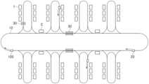
도 1은 본 발명에 따른 제조 공장에서 물품을 이송하기 위한 물품 반송 시스템의 개략적인 레이아웃을 도시한다.
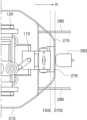
도 2는 전면에서 바라본 본 발명에 따른 반송 대차를 도시한다.
도 3은 측면에서 바라본 반송 대차를 도시한다.
도 4는 상부에서 바라본 반송 대차를 도시한다.
도 5는 반송 대차에서 범퍼 유닛의 구성을 도시한다.
도 6 및 도 7은 반송 대차에서 테일 플레이트를 설명하기 위한 도면이다.Figure 1 shows a schematic layout of an article transport system for conveying articles in a manufacturing plant according to the invention.
Figure 2 shows a transport cart according to the present invention viewed from the front.
Figure 3 shows the transport bogie viewed from the side.
Figure 4 shows the transport bogie viewed from above.
Figure 5 shows the configuration of the bumper unit in the transport bogie.
Figures 6 and 7 are diagrams for explaining the tail plate in the transport cart.
이하, 첨부한 도면을 참고로 하여 본 발명의 실시예들에 대하여 본 발명이 속하는 기술 분야에서 통상의 지식을 가진 자가 용이하게 실시할 수 있도록 상세히 설명한다. 본 발명은 여러 가지 상이한 형태로 구현될 수 있으며 여기에서 설명하는 실시예들에 한정되지 않는다.Hereinafter, with reference to the attached drawings, embodiments of the present invention will be described in detail so that those skilled in the art can easily practice the present invention. The invention may be implemented in many different forms and is not limited to the embodiments described herein.
본 발명을 명확하게 설명하기 위해서 설명과 관계없는 부분은 생략하였으며, 명세서 전체를 통하여 동일 또는 유사한 구성요소에 대해서는 동일한 참조 부호를 붙이도록 한다.In order to clearly explain the present invention, parts that are not relevant to the description are omitted, and identical or similar components are assigned the same reference numerals throughout the specification.
또한, 여러 실시예들에 있어서, 동일한 구성을 가지는 구성요소에 대해서는 동일한 부호를 사용하여 대표적인 실시예에서만 설명하고, 그 외의 다른 실시예에서는 대표적인 실시예와 다른 구성에 대해서만 설명하기로 한다.Additionally, in various embodiments, components having the same configuration will be described using the same symbols only in the representative embodiment, and in other embodiments, only components that are different from the representative embodiment will be described.
명세서 전체에서, 어떤 부분이 다른 부분과 "연결(또는 결합)"되어 있다고 할 때, 이는 "직접적으로 연결(또는 결합)"되어 있는 경우뿐만 아니라, 다른 부재를 사이에 두고 "간접적으로 연결(또는 결합)"된 것도 포함한다. 또한, 어떤 부분이 어떤 구성요소를 "포함"한다고 할 때, 이는 특별히 반대되는 기재가 없는 한 다른 구성요소를 제외하는 것이 아니라 다른 구성요소를 더 포함할 수 있는 것을 의미한다.Throughout the specification, when a part is said to be "connected (or combined)" with another part, this means not only "directly connected (or combined)" but also "indirectly connected (or combined)" with another member in between. Also includes “combined” ones. Additionally, when a part "includes" a certain component, this means that it may further include other components, rather than excluding other components, unless specifically stated to the contrary.
다르게 정의되지 않는 한, 기술적이거나 과학적인 용어를 포함해서 여기서 사용되는 모든 용어들은 본 발명이 속하는 기술 분야에서 통상의 지식을 가진 자에 의해 일반적으로 이해되는 것과 동일한 의미를 가지고 있다. 일반적으로 사용되는 사전에 정의되어 있는 것과 같은 용어들은 관련 기술의 문맥 상 가지는 의미와 일치하는 의미를 가지는 것으로 해석되어야 하며, 본 출원에서 명백하게 정의하지 않는 한, 이상적이거나 과도하게 형식적인 의미로 해석되지 않는다.Unless otherwise defined, all terms used herein, including technical or scientific terms, have the same meaning as commonly understood by a person of ordinary skill in the technical field to which the present invention pertains. Terms defined in commonly used dictionaries should be interpreted as having a meaning consistent with the meaning in the context of the related technology, and unless explicitly defined in the present application, should not be interpreted in an ideal or excessively formal sense. No.
도 1은 본 발명에 따른 제조 공장에서 물품을 이송하기 위한 물품 반송 시스템의 개략적인 레이아웃을 도시한다. 이하에서는 본 발명이 적용되는 제조 공장으로서 반도체 제품을 제조하는 반도체 제조 공장을 예로서 설명한다. 다만, 본 발명이 적용될 수 있는 제조 공장의 범위는 특정 타입에 제한되는 것이 아니며 다양한 산업군의 제조 공장에 적용될 수 있다. 예를 들어, 본 발명의 물품 반송 시스템은 디스플레이 패널, 전자 기기, 자동차, 또는 2차 전지 등의 제품을 생산하는 다른 종류의 제조 공장에 적용될 수 있다.Figure 1 shows a schematic layout of an article transport system for conveying articles in a manufacturing plant according to the invention. Hereinafter, a semiconductor manufacturing plant manufacturing semiconductor products will be described as an example as a manufacturing plant to which the present invention is applied. However, the scope of manufacturing plants to which the present invention can be applied is not limited to a specific type and can be applied to manufacturing plants in various industries. For example, the product transport system of the present invention can be applied to other types of manufacturing plants that produce products such as display panels, electronic devices, automobiles, or secondary batteries.
제조 공장은 하나 또는 그 이상의 클린룸으로 구성되며, 각 클린룸에 반도체 제조 공정을 수행하기 위한 제조 설비(1)들이 설치될 수 있다. 일반적으로, 기판(예: 웨이퍼)에 복수의 제조 공정들이 반복 수행됨으로써 최종적으로 처리된 기판이 완성될 수 있는데, 특정 반도체 제조 설비(1)에서 제조 공정이 완료되면 다음 제조 공정을 위한 제조 설비(1)로 기판이 반송된다. 여기서 웨이퍼는 복수개의 기판들을 수용할 수 있는 반송 용기(예: front opening unified pod, FOUP)에 보관된 상태로 반송될 수 있다. 웨이퍼들이 수납된 반송 용기는 반송 대차(20)에 의해 반송될 수 있다. 반송 대차(20)는 천정에 설치된 주행 레일(10)을 따라 주행하는 OHT(overhead hoist transport)로 지칭될 수 있다.A manufacturing plant consists of one or more clean rooms, and manufacturing facilities 1 for performing a semiconductor manufacturing process may be installed in each clean room. In general, the final processed substrate can be completed by repeatedly performing a plurality of manufacturing processes on a substrate (e.g., a wafer). Once the manufacturing process is completed in a specific semiconductor manufacturing facility 1, a manufacturing facility for the next manufacturing process ( 1) The substrate is transported. Here, the wafer may be transported while stored in a transport container (eg, front opening unified pod, FOUP) that can accommodate a plurality of substrates. The transfer container containing the wafers can be transferred by the
도 1을 참고하면, 제조 공장 내 공정을 수행하기 위한 제조 설비(1)가 설치되고, 제조 설비(1) 간 물품을 이송하는 반송 대차(20)와 반송 대차(20)의 주행 경로를 제공하는 주행 레일(10)이 제공된다. 여기서, 반송 대차(20)가 제조 설비(1)들 사이에서 물품을 반송할 때, 물품이 곧바로 특정 제조 설비(1)에서 다른 제조 설비(1)로 반송될 수도 있고, 물품이 스토커 설비(30)에 보관된 이후 다른 제조 설비로 반송될 수 있다.Referring to FIG. 1, a manufacturing facility (1) is installed to perform a process within a manufacturing plant, and a transport cart (20) for transporting goods between the manufacturing facilities (1) and a travel path for the transport cart (20) are provided. A running
도 2 및 도 3은 본 발명에 따른 제조 공장에서 물품을 이송하는 반송 대차(20)를 도시한다. 도 2는 전면에서 바라본 반송 대차(20)를 도시하고, 도 3은 측면에서 바라본 반송 대차(20)를 도시한다.2 and 3 show a
도 2를 참조하면, 주행 레일(10)은, 수평 방향으로 서로 이격되고 서로 짝을 이루는 한 쌍의 레일 부재를 포함하고, 레일 서포트(15)들에 의하여 제조 공장의 천장 측에 설치된다. 레일 서포트(15) 각각은, 하단 부분이 한 쌍의 레일 부재를 지지하고, 상단 부분이 반도체 제조 공장의 천장에 정착될 수 있다. 한 쌍의 레일 부재는 상측에 주행 면을 제공하도록 형성될 수 있다.Referring to FIG. 2, the running
도 2에 도시된 바와 같이, 반송 대차(20)로 전력을 공급하기 위한 급전 장치(40)는 주행 레일(10)의 하부에 설치된 케이블 설치 구조물(42)과 케이블 설치 구조물(42)에 설치된 급전 케이블(41)을 포함한다. 급전 케이블(41)은 구동 전력을 제공하는 반송 대차(20)의 수전 장치로 전류를 유도한다.As shown in FIG. 2, the
도 2를 참조하면, 반송 대차(20)는 주행 레일(10)을 따라 주행하는 주행 유닛(100), 그리고 주행 유닛(100)의 하부에서 물품을 지지하는 호이스트 유닛(200)을 포함한다. 호이스트 유닛(200)은 주행 유닛(100)과 함께 이동하며 제조 설비(1)로 물품을 이적재한다.Referring to FIG. 2, the
주행 유닛(100)은 차체(110)와 주행 휠(120)들을 포함한다. 차체(110)에는 좌우 방향으로 연장된 차축이 장착된다. 차축은 복수로 제공되고 전후 방향으로 서로 이격될 수 있다. 주행 휠(120)들은 차체(110)가 주행 레일(10)의 안내에 따라 주행 가능하도록 차체(110)에 이동성을 부여하는 휠이다. 주행 휠(120)들은, 차축의 양단 부분에 각각 장착되고, 한 쌍의 주행 레일(10)의 상부면에 각각 접촉되어 회전할 수 있다. 주행 유닛(100)은 주행 휠(120)들을 회전시키기 위한 동력을 제공하는 휠 구동 유닛(130)을 더 포함한다. 일례로, 휠 구동 유닛(130)은 차축을 회전시키도록 구성될 수 있다.The traveling
호이스트 유닛(200)은 프레임(210)을 포함한다. 프레임(210)은 주행 레일(10)의 하방에서 주행 유닛(100)과 서로 연결된다. 프레임(210)은 상부가 차체(110)의 하부에 단수 또는 복수의 연결기에 의하여 연결될 수 있다. 프레임(210)은 물품이 수용되는 수용 공간을 제공한다. 프레임(210)은 물품을 수용 공간에서 수평 방향(X 방향)으로 이동시키고 하측 방향으로 이동시킬 수 있게 좌우 양옆 및 하측이 모두 개방된 구조를 가지도록 형성된다.Hoist
게다가, 호이스트 유닛(200)은, 물품을 그립하거나 언그립하기 위한 핸드 유닛(220), 그리고 핸드 유닛(220)을 제1 위치와 제2 위치 간에 이동시키는 핸드 이동 유닛을 더 포함한다. 제1 위치는 핸드 유닛(220)이 그립한 물품이 프레임(210)의 수용 공간에 수용되는 위치이고, 제2 위치는 이러한 제1 위치로부터 벗어난 위치에 해당하는 프레임(210)의 외부이다. 호이스트 유닛(200)은 핸드 이동 유닛으로서 수직 구동 유닛(230), 회전 구동 유닛(240) 및 수평 구동 유닛(250)을 포함한다.In addition, the hoist
핸드 유닛(220)은, 물품에 대한 그립 및 언그립을 수행하는 핸드, 그리고 핸드를 지지하는 핸드 서포트를 포함할 수 있다. 수직 구동 유닛(230)은 핸드 유닛(220)을 상하 방향으로 이동시킨다. 수직 구동 유닛(230)은 적어도 하나 이상의 벨트(belt)를 드럼(drum)에 대하여 와인딩(winding)하거나 언와인딩(unwinding)하는 방식으로 핸드 유닛(220)을 수직 방향(Z 방향)으로 이동시킬 수 있다. 회전 구동 유닛(240)은 핸드 유닛(220)을 수직 방향의 축을 중심으로 회전시키고, 수평 구동 유닛(250)은 핸드 유닛(220)을 좌우 방향으로 이동시킨다. 일례로, 핸드 유닛(220)을 수직 구동 유닛(230)에 의하여 수직 방향으로 이동시키고, 수직 구동 유닛(230)을 회전 구동 유닛(240)에 의하여 수직 방향의 축을 중심으로 회전시키며, 회전 구동 유닛(240)을 수평 구동 유닛(250)에 의하여 좌우 방향으로 이동시킴으로써, 핸드 유닛(220)에 의하여 그립된 물품을 수직 방향으로 이동시키거나 수직 방향의 축을 중심으로 회전시키거나 좌우 방향으로 이동시킬 수 있다.The
호이스트 유닛(200)은 프레임(210)의 전면(210F)에 위치한 대차 감지 센서(260)를 포함한다. 대차 감지 센서(260)는 프레임 전면(210F)의 상측 중심부에 위치하며 전방에 위치한 다른 반송 대차(20)의 위치(방향 및 거리)를 검출할 수 있다. 대차 감지 센서(260)는 라이다(Lidar), 레이더, 또는 카메라 등으로 구현될 수 있다.The hoist
한편, 호이스트 유닛(200)의 상단부 전면(210F) 및 후면(210R)에는 다른 반송 대차(20)와의 충돌시 충격을 저감하기 위한 범퍼 유닛(270)이 구성될 수 있다. 범퍼 유닛(270)은 프레임 전면(210F)에 구성된 전방 범퍼 유닛(270F)과 프레임 후면(210R)에 구성된 후방 범퍼 유닛(270R)을 포함할 수 있다. 또한, 프레임(210)의 후면(210R)에 테일 플레이트(280)가 구비된다. 범퍼 유닛(270) 및 테일 플레이트(280)의 구성에 대해서는 도 4 내지 도 7을 참고하여 설명하도록 한다.Meanwhile, a
도 4는 상부에서 바라본 반송 대차(20)를 도시한다. 도 4를 참고하면 프레임(210)은 전후 방향으로 길게 형성되고, 전방(F)과 후방(R)에 각각 전방 범퍼 유닛(270F) 및 후방 범퍼 유닛(270R)이 구성된다. 즉, 범퍼 유닛(270)은 프레임(210)의 전면(210F)에 구비된 전방 범퍼 유닛(270F)과, 프레임(210)의 후면(210R)에 구비된 후방 범퍼 유닛(270R)을 포함할 수 있다.Figure 4 shows the
전방 범퍼 유닛(270F)은, 프레임(210)의 전면 중심부에 결합되어 전방으로 돌출된 축을 갖는 전방 브라켓(271), 프레임(210)의 전면 측부 양측에 결합되어 전방(F)으로 돌출 절곡되는 전방 커버 플레이트(272), 전방 커버 플레이트(272)의 외측에 결합되는 고무 범퍼 부재(273)를 포함할 수 있다.The
후방 범퍼 유닛(270R)은 프레임(210)의 후면 중심부에 결합되어 후방으로 돌출된 축을 갖는 후방 브라켓(274), 프레임(210)의 후면 측부의 양측에 결합되어 후방(R)으로 돌출 절곡되는 후방 커버 플레이트(275), 후방 브라켓(274)과 후방 커버 플레이트(275) 사이에 구비되어 완충력을 발생시키는 댐퍼 부재(276)를 포함할 수 있다.The
전방 범퍼 유닛(270F)과 후방 범퍼 유닛(270R)이 프레임(210)에 장착되기 이전의 상태가 도 5에 도시된다. 전방 브라켓(271)은 프레임(210)의 전면 중심부와 브라켓 축(271B)을 결합시키는 브라켓(271A), 전방(F)을 향하여 연장되는 브라켓 축(271B), 브라켓 축(271B)과 전방 커버 플레이트(272)를 결합시키는 브라켓(271C)을 포함한다. 전방 커버 플레이트(272)는 프레임(210)의 양측에 체결되며 전방 브라켓(271)을 통해 프레임(210)의 전면 중앙부에도 고정 체결된다. 전방 커버 플레이트(272)의 외측에는 고무 범퍼 부재(273)가 장착될 수 있다.The state before the
후방 브라켓(274)은 프레임(210)의 후면 중심부와 브라켓 축(274B)을 결합시키는 브라켓(274A), 후방(R)을 향하여 연장되는 브라켓 축(274B), 브라켓 축(274B)과 후방 커버 플레이트(275)를 결합시키는 브라켓(274C)을 포함한다. 후방 커버 플레이트(275)는 프레임(210)의 양측에 체결되며 후방 브라켓(274)을 통해 프레임(210)의 후면 중앙부에도 고정 체결된다. 후방 브라켓(274)과 후방 커버 플레이트(275) 사이에는 완충력을 발생시키기 위한 댐퍼 부재(276)가 삽입될 수 있다.The
본 발명에 따르면, 범퍼 유닛(270)은 주행 유닛(100)의 양 끝단(100E)보다 돌출되도록 형성될 수 있다. 예를 들어, 도 6을 참고하면, 후방 범퍼 유닛(270R)의 후방 커버 플레이트(275)는 주행 유닛(100)의 차체(110)의 후방 끝단(100E) 보다 후방(R)으로 돌출되어 형성될 수 있다. 유사하게, 반송 대차(20)의 전면에도 유사하게 전방 범퍼 유닛(270F)이 주행 유닛(100)의 전방 끝단 보다 전방(F)으로 돌출되어 형성될 수 있다. 범퍼 유닛(270)이 주행 유닛(100)의 양 끝단(100E) 보다 돌출되어 형성됨으로써 다른 반송 대차(20)와의 충돌이 발생하더라도 주행 유닛(100)에 손상이 발생하는 것을 방지할 수 있다.According to the present invention, the
한편, 프레임(210)의 후면(210R)에는 한 쌍의 테일 플레이트(280)가 구비될 수 있다. 테일 플레이트(280)는 다른 반송 대차(20)에 의해 검출될 수 있도록 반사판으로서 기능할 수 있다. 테일 플레이트(280)를 단순히 프레임(210)의 후면(210R)의 중심부에 설치할 경우, 반송 대차(20)가 서로 충돌할 때 전방의 반송 대차(20)의 테일 플레이트(280)에 의해 후방의 반송 대차(20)의 전방에 위치한 대차 감지 센서(260)가 파손될 수 있다. 대차 감지 센서(260)는 보통 높은 비용이 발생하고 공급받기 어려운 부품에 해당하기 때문에 대차 감지 센서(260)가 파손될 경우 해당 반송 대차(20)는 긴 시간 동안 사용될 수 없으므로 치명적이다. 따라서, 반송 대차(20)가 서로 충돌하는 경우에도 대차 감지 센서(260)의 파손을 막는 것이 중요하다. 따라서, 본 발명의 실시예에 따른 테일 플레이트(280)는 후방에 위치한 반송 대차(20)의 대차 감지 센서(260)와 접촉하지 않도록 양측에 한 쌍으로 구비될 수 있다.Meanwhile, a pair of
도 6 및 도 7을 참고하면, 테일 플레이트(280)는 범퍼 유닛(270)의 하부에 구비될 수 있다. 테일 플레이트(280)는 후방의 반송 대차(20)의 전면에 위치한 대차 감지 센서(260)가 위치한 곳의 양측에서 간섭되지 않도록 구비될 수 있다. 테일 플레이트(280)의 위치는 후방에 위치한 다른 반송 대차(20)와의 충돌시 다른 반송 대차(20)의 전면 중심부에 구비된 대차 감지 센서(260)와의 충돌이 회피 되도록 결정될 수 있다. 테일 플레이트(280)는 대차 감지 센서(260)로부터 조사된 광을 반사하도록 구성된다.Referring to FIGS. 6 and 7 , the
테일 플레이트(280)는 범퍼 유닛(270)의 끝단(270E)만큼 후방으로 돌출될 수 있다. 테일 플레이트(280)는 범퍼 유닛(270)의 끝단(270E)만큼 후방으로 돌출됨으로써 반송 대차(20) 간의 충돌이 발생하는 경우에도 파손되지 않도록 구성될 수 있다.The
본 실시예 및 본 명세서에 첨부된 도면은 본 발명에 포함되는 기술적 사상의 일부를 명확하게 나타내고 있는 것에 불과하며, 본 발명의 명세서 및 도면에 포함된 기술적 사상의 범위 내에서 당업자가 용이하게 유추할 수 있는 변형예와 구체적인 실시예는 모두 본 발명의 권리범위에 포함되는 것이 자명하다고 할 것이다.This embodiment and the drawings attached to this specification only clearly show a part of the technical idea included in the present invention, and those skilled in the art can easily infer within the scope of the technical idea included in the specification and drawings of the present invention. It will be apparent that all possible modifications and specific embodiments are included in the scope of the present invention.
따라서, 본 발명의 사상은 설명된 실시예에 국한되어 정해져서는 아니 되며, 후술하는 특허청구범위뿐 아니라 이 특허청구범위와 균등하거나 등가적 변형이 있는 모든 것들은 본 발명 사상의 범주에 속한다고 할 것이다.Therefore, the spirit of the present invention should not be limited to the described embodiments, and the scope of the patent claims described below as well as all things that are equivalent or equivalent to the scope of the claims will be said to fall within the scope of the spirit of the present invention. .
10: 주행 레일
20: 반송 대차
100: 주행 유닛
200: 호이스트 유닛
210: 프레임
220: 핸드 유닛
260: 대차 감지 센서
270: 범퍼 유닛
271: 전방 브라켓
272: 전방 커버 플레이트
273: 고무 범퍼 부재
274: 후방 브라켓
275: 후방 커버 플레이트
276: 댐퍼 부재
280: 테일 플레이트10: Running rail
20: Return truck
100: driving unit
200: Hoist unit
210: frame
220: hand unit
260: Truck detection sensor
270: Bumper unit
271: Front bracket
272: Front cover plate
273: Rubber bumper member
274: Rear bracket
275: rear cover plate
276: Damper member
280: tail plate
Claims (20)
Translated fromKorean주행 레일을 따라 주행하는 주행 유닛; 및
상기 주행 유닛의 하부에서 물품을 지지하는 호이스트 유닛을 포함하고,
상기 호이스트 유닛은,
프레임; 및
상기 프레임의 후면에 구비되어 후방으로 돌출된 한 쌍의 테일 플레이트를 포함하는 반송 대차.
In the transport bogie that transports goods from the manufacturing plant,
A traveling unit traveling along a traveling rail; and
It includes a hoist unit supporting articles at the lower part of the traveling unit,
The hoist unit is,
frame; and
A transport bogie including a pair of tail plates provided on the rear of the frame and protruding rearward.
상기 테일 플레이트는 상기 프레임의 후방에 구비된 범퍼 유닛의 하부에 구비되는 반송 대차.
According to paragraph 1,
The tail plate is a transport bogie provided on a lower part of a bumper unit provided at the rear of the frame.
상기 테일 플레이트는 상기 범퍼 유닛의 끝단만큼 후방으로 돌출되는 반송 대차.
According to paragraph 2,
The tail plate is a transport bogie that protrudes rearward as far as the end of the bumper unit.
상기 테일 플레이트의 위치는 후방에 위치한 다른 반송 대차와의 충돌시 상기 다른 반송 대차의 전면 중심부에 구비된 대차 감지 센서와의 충돌이 회피 되도록 결정되는 반송 대차.
According to paragraph 1,
The position of the tail plate is determined to avoid a collision with a truck detection sensor provided at the center of the front of the other transport truck in the event of a collision with another transport truck located at the rear.
상기 테일 플레이트는 상기 대차 감지 센서로부터 조사된 광을 반사하도록 구성되는 반송 대차.
According to paragraph 4,
The tail plate is a transport cart configured to reflect light emitted from the cart detection sensor.
주행 레일을 따라 주행하는 주행 유닛; 및
상기 주행 유닛의 하부에서 물품을 지지하는 호이스트 유닛을 포함하고,
상기 호이스트 유닛은,
프레임; 및
상기 프레임의 전면 및 후면에 각각 구비된 범퍼 유닛; 및
상기 프레임의 후면에 구비되어 후방으로 돌출된 한 쌍의 테일 플레이트를 포함하는 반송 대차.
In the transport bogie that transports goods from the manufacturing plant,
A traveling unit traveling along a traveling rail; and
It includes a hoist unit supporting articles at the lower part of the traveling unit,
The hoist unit is,
frame; and
Bumper units provided on the front and rear of the frame, respectively; and
A transport bogie including a pair of tail plates provided on the rear of the frame and protruding rearward.
상기 범퍼 유닛은,
상기 프레임의 전면에 구비된 전방 범퍼 유닛; 및
상기 프레임의 후면에 구비된 후방 범퍼 유닛을 포함하는 반송 대차.
According to clause 6,
The bumper unit is,
a front bumper unit provided on the front of the frame; and
A transport bogie including a rear bumper unit provided at the rear of the frame.
상기 전방 범퍼 유닛은,
상기 프레임의 전면 중심부에 결합되어 전방으로 돌출된 축을 갖는 전방 브라켓;
상기 프레임의 전면 측부 양측에 결합되어 전방으로 돌출 절곡되는 전방 커버 플레이트; 및
상기 전방 커버 플레이트의 외측에 결합되는 고무 범퍼 부재를 포함하는 반송 대차.
In clause 7,
The front bumper unit,
a front bracket coupled to the front center of the frame and having a shaft protruding forward;
a front cover plate coupled to both sides of the front side of the frame and protruding and bent forward; and
A transport bogie including a rubber bumper member coupled to the outside of the front cover plate.
상기 후방 범퍼 유닛은,
상기 프레임의 후면 중심부에 결합되어 후방으로 돌출된 축을 갖는 후방 브라켓;
상기 프레임의 후면 측부의 양측에 결합되어 전방으로 돌출 절곡되는 후방 커버 플레이트; 및
상기 후방 브라켓과 상기 후방 커버 플레이트 사이에 구비되어 완충력을 발생시키는 댐퍼 부재를 포함하는 반송 대차.
In clause 7,
The rear bumper unit,
a rear bracket coupled to the rear center of the frame and having a shaft protruding rearward;
a rear cover plate coupled to both sides of the rear side of the frame and protruding and bent forward; and
A transport bogie including a damper member provided between the rear bracket and the rear cover plate to generate a buffering force.
상기 범퍼 유닛은 상기 주행 유닛의 양 끝단보다 돌출되도록 형성되는 반송 대차.
According to clause 6,
The bumper unit is a transport bogie formed to protrude beyond both ends of the traveling unit.
상기 테일 플레이트는 상기 프레임에서 상기 범퍼 유닛의 하부에 구비되는 반송 대차.
According to clause 6,
The tail plate is a transport bogie provided on a lower part of the bumper unit in the frame.
상기 테일 플레이트는 상기 범퍼 유닛의 끝단만큼 후방으로 돌출되는 반송 대차.
According to clause 11,
The tail plate is a transport bogie that protrudes rearward as far as the end of the bumper unit.
상기 테일 플레이트의 위치는 후방에 위치한 다른 반송 대차와의 충돌시 상기 다른 반송 대차의 전면 중심부에 구비된 대차 감지 센서와의 충돌이 회피 되도록 결정되는 반송 대차.
According to clause 6,
The position of the tail plate is determined to avoid a collision with a truck detection sensor provided at the center of the front of the other transport truck in the event of a collision with another transport truck located at the rear.
상기 테일 플레이트는 상기 대차 감지 센서로부터 조사된 광을 반사하도록 구성되는 반송 대차.
According to clause 13,
The tail plate is a transport cart configured to reflect light emitted from the cart detection sensor.
물품을 이송하는 반송 대차; 및
상기 반송 대차의 주행 경로를 제공하는 주행 레일을 포함하고,
상기 반송 대차는,
주행 레일을 따라 주행하는 주행 유닛;
상기 주행 유닛의 하부에서 물품을 지지하는 호이스트 유닛을 포함하고,
상기 호이스트 유닛은,
프레임;
상기 프레임의 전면 및 후면에 각각 구비된 범퍼 유닛; 및
상기 프레임의 후면에 구비되어 후방으로 돌출된 한 쌍의 테일 플레이트를 포함하는 물품 반송 시스템.
In the product transport system of a manufacturing plant,
A transport truck that transports goods; and
It includes a traveling rail that provides a traveling path for the transport bogie,
The transport bogie is,
A traveling unit traveling along a traveling rail;
It includes a hoist unit supporting articles at the lower part of the traveling unit,
The hoist unit is,
frame;
Bumper units provided on the front and rear of the frame, respectively; and
A product transport system comprising a pair of tail plates provided on the rear of the frame and protruding rearward.
상기 범퍼 유닛은,
상기 프레임의 전면에 구비된 전방 범퍼 유닛; 및
상기 프레임의 후면에 구비된 후방 범퍼 유닛을 포함하는 물품 반송 시스템.
According to clause 15,
The bumper unit is,
a front bumper unit provided on the front of the frame; and
A product transport system including a rear bumper unit provided at the rear of the frame.
상기 전방 범퍼 유닛은,
상기 프레임의 전면 중심부에 결합되어 전방으로 돌출된 축을 갖는 전방 브라켓;
상기 프레임의 전면 측부 양측에 결합되어 전방으로 돌출 절곡되는 전방 커버 플레이트; 및
상기 전방 커버 플레이트의 외측에 결합되는 고무 범퍼 부재를 포함하는 물품 반송 시스템.
According to clause 16,
The front bumper unit,
a front bracket coupled to the front center of the frame and having a shaft protruding forward;
a front cover plate coupled to both sides of the front side of the frame and protruding and bent forward; and
An article transport system including a rubber bumper member coupled to the outside of the front cover plate.
상기 후방 범퍼 유닛은,
상기 프레임의 후면 중심부에 결합되어 후방으로 돌출된 축을 갖는 후방 브라켓;
상기 프레임의 후면 측부의 양측에 결합되어 전방으로 돌출 절곡되는 후방 커버 플레이트; 및
상기 후방 브라켓과 상기 후방 커버 플레이트 사이에 구비되어 완충력을 발생시키는 댐퍼 부재를 포함하는 물품 반송 시스템.
According to clause 16,
The rear bumper unit,
a rear bracket coupled to the rear center of the frame and having a shaft protruding rearward;
a rear cover plate coupled to both sides of the rear side of the frame and protruding and bent forward; and
A product transport system including a damper member provided between the rear bracket and the rear cover plate to generate a buffering force.
상기 테일 플레이트는 상기 프레임에서 상기 범퍼 유닛의 하부에 구비되는 물품 반송 시스템.
According to clause 15,
The tail plate is a product transport system provided in the frame at a lower portion of the bumper unit.
상기 테일 플레이트의 위치는 후방에 위치한 다른 반송 대차와의 충돌시 상기 다른 반송 대차의 전면 중심부에 구비된 대차 감지 센서와의 충돌이 회피 되도록 결정되는 물품 반송 시스템.
According to clause 15,
The position of the tail plate is determined to avoid collision with a cart detection sensor provided at the front center of the other transport cart when colliding with another transport cart located at the rear.
Priority Applications (5)
| Application Number | Priority Date | Filing Date | Title |
|---|---|---|---|
| KR1020220080920AKR20240002833A (en) | 2022-06-30 | 2022-06-30 | Transport vehicle for transporting article in manufacturing factory and article transport system including the same |
| JP2023003137AJP7504241B2 (en) | 2022-06-30 | 2023-01-12 | Transport vehicle for transporting items in a manufacturing plant, and item transport system including the same |
| CN202310041283.3ACN117326276A (en) | 2022-06-30 | 2023-01-13 | Conveying trolleys and article conveying systems equipped with them |
| US18/117,617US20240006213A1 (en) | 2022-06-30 | 2023-03-06 | Transport vehicle for transporting article in manufacturing factory and article transport system including the same |
| KR1020250016623AKR102870018B1 (en) | 2025-02-10 | Transport vehicle for transporting article in manufacturing factory and article transport system including the same |
Applications Claiming Priority (1)
| Application Number | Priority Date | Filing Date | Title |
|---|---|---|---|
| KR1020220080920AKR20240002833A (en) | 2022-06-30 | 2022-06-30 | Transport vehicle for transporting article in manufacturing factory and article transport system including the same |
Related Child Applications (1)
| Application Number | Title | Priority Date | Filing Date |
|---|---|---|---|
| KR1020250016623ADivisionKR102870018B1 (en) | 2025-02-10 | Transport vehicle for transporting article in manufacturing factory and article transport system including the same |
Publications (1)
| Publication Number | Publication Date |
|---|---|
| KR20240002833Atrue KR20240002833A (en) | 2024-01-08 |
Family
ID=89274298
Family Applications (1)
| Application Number | Title | Priority Date | Filing Date |
|---|---|---|---|
| KR1020220080920ACeasedKR20240002833A (en) | 2022-06-30 | 2022-06-30 | Transport vehicle for transporting article in manufacturing factory and article transport system including the same |
Country Status (4)
| Country | Link |
|---|---|
| US (1) | US20240006213A1 (en) |
| JP (1) | JP7504241B2 (en) |
| KR (1) | KR20240002833A (en) |
| CN (1) | CN117326276A (en) |
Family Cites Families (14)
| Publication number | Priority date | Publication date | Assignee | Title |
|---|---|---|---|---|
| JP3414484B2 (en)* | 1994-04-14 | 2003-06-09 | 株式会社ダイフク | Transport device using train |
| JP2777877B2 (en)* | 1995-05-17 | 1998-07-23 | 日本ファイリング株式会社 | Truck transport device |
| JP2682970B2 (en)* | 1995-06-30 | 1997-11-26 | 川崎重工業株式会社 | Bumper device for carrier truck |
| US8272827B2 (en)* | 2005-11-07 | 2012-09-25 | Bufano Michael L | Reduced capacity carrier, transport, load port, buffer system |
| JP2010067144A (en)* | 2008-09-12 | 2010-03-25 | Muratec Automation Co Ltd | Conveyance system and collision prevention system |
| JP5883604B2 (en)* | 2011-09-30 | 2016-03-15 | 株式会社岡村製作所 | Article conveying device |
| KR101743465B1 (en)* | 2015-11-04 | 2017-06-07 | 주식회사 에스에프에이 | Carriage system and disabled car traction method therefor |
| JP6946965B2 (en)* | 2017-11-22 | 2021-10-13 | 村田機械株式会社 | Transport system |
| CN113056406B (en)* | 2018-10-29 | 2024-03-26 | 村田机械株式会社 | Bridge crane, bridge crane system, and obstacle detection method |
| JP7539060B2 (en)* | 2019-03-25 | 2024-08-23 | 北陽電機株式会社 | Object detection system, transport vehicle, and object detection device |
| CN210478615U (en)* | 2019-06-06 | 2020-05-08 | 李丹 | High-safety automobile bumper |
| KR102049541B1 (en)* | 2019-07-17 | 2019-11-27 | 서광모 | Track vehicle system with three-way rails |
| KR102511085B1 (en)* | 2020-08-31 | 2023-03-15 | 세메스 주식회사 | Article transport vehicle and article transport facility |
| CN112830175A (en)* | 2021-02-25 | 2021-05-25 | 天海欧康科技信息(厦门)有限公司 | A rail logistics trolley |
- 2022
- 2022-06-30KRKR1020220080920Apatent/KR20240002833A/ennot_activeCeased
- 2023
- 2023-01-12JPJP2023003137Apatent/JP7504241B2/enactiveActive
- 2023-01-13CNCN202310041283.3Apatent/CN117326276A/enactivePending
- 2023-03-06USUS18/117,617patent/US20240006213A1/enactivePending
Also Published As
| Publication number | Publication date |
|---|---|
| JP7504241B2 (en) | 2024-06-21 |
| CN117326276A (en) | 2024-01-02 |
| US20240006213A1 (en) | 2024-01-04 |
| KR20250026216A (en) | 2025-02-25 |
| JP2024006912A (en) | 2024-01-17 |
Similar Documents
| Publication | Publication Date | Title |
|---|---|---|
| US20120321423A1 (en) | Dynamic Storage and Transfer System Integrated with Autonomous Guided/Roving Vehicle | |
| CN108466811B (en) | Article carrier | |
| EP3944930B1 (en) | Unmanned ground-based hygiene maintenance vehicle and method for improving hygiene conditions | |
| JP2008056450A (en) | Carried object storage system | |
| WO2019102743A1 (en) | Traveling dolly | |
| KR102511085B1 (en) | Article transport vehicle and article transport facility | |
| US7806648B2 (en) | Transportation system and transportation method | |
| JP7323059B2 (en) | carrier system | |
| KR20240002833A (en) | Transport vehicle for transporting article in manufacturing factory and article transport system including the same | |
| KR102870018B1 (en) | Transport vehicle for transporting article in manufacturing factory and article transport system including the same | |
| JP2022061499A (en) | Manufacturing factory goods transfer system | |
| KR102501706B1 (en) | Transport vehicle system | |
| JP5365302B2 (en) | Traveling vehicle system | |
| KR102655946B1 (en) | Transferring apparatus | |
| KR20230163680A (en) | Transper system for manufacturing Semiconductor and transper method | |
| KR20230075118A (en) | Transferring apparatus | |
| KR20220005811A (en) | Article transport facility and article transport method | |
| KR102628404B1 (en) | Stocker and article transport facility | |
| JP2003309163A (en) | Unmanned carrier system | |
| KR20230097931A (en) | Aerial work platform having article transport vehicle anti-collision function | |
| JP2002060007A (en) | Conveying system | |
| KR102668412B1 (en) | Crane device, driving method thereof, and stocker including same | |
| JP2007165367A (en) | Sheet-fed work conveyance system | |
| KR20240098775A (en) | Transport vehicle for transporting article in manufacturing line and article transport system including the same | |
| KR20240135538A (en) | Transport vehicle |
Legal Events
| Date | Code | Title | Description |
|---|---|---|---|
| PA0109 | Patent application | Patent event code:PA01091R01D Comment text:Patent Application Patent event date:20220630 | |
| PA0201 | Request for examination | ||
| PG1501 | Laying open of application | ||
| E902 | Notification of reason for refusal | ||
| PE0902 | Notice of grounds for rejection | Comment text:Notification of reason for refusal Patent event date:20240110 Patent event code:PE09021S01D | |
| E601 | Decision to refuse application | ||
| PE0601 | Decision on rejection of patent | Patent event date:20240715 Comment text:Decision to Refuse Application Patent event code:PE06012S01D | |
| AMND | Amendment | ||
| PX0901 | Re-examination | Patent event code:PX09012R01I Patent event date:20241014 Comment text:Amendment to Specification, etc. | |
| E601 | Decision to refuse application | ||
| E801 | Decision on dismissal of amendment | ||
| PE0601 | Decision on rejection of patent | Patent event date:20241111 Comment text:Decision to Refuse Application Patent event code:PE06012S01D | |
| PE0801 | Dismissal of amendment | Patent event code:PE08012E01D Comment text:Decision on Dismissal of Amendment Patent event date:20241111 |