KR20230166108A - Material supply sheet - Google Patents
Material supply sheetDownload PDFInfo
- Publication number
- KR20230166108A KR20230166108AKR1020237037102AKR20237037102AKR20230166108AKR 20230166108 AKR20230166108 AKR 20230166108AKR 1020237037102 AKR1020237037102 AKR 1020237037102AKR 20237037102 AKR20237037102 AKR 20237037102AKR 20230166108 AKR20230166108 AKR 20230166108A
- Authority
- KR
- South Korea
- Prior art keywords
- protective cover
- sheet
- film
- adhesive layer
- cover member
- Prior art date
- Legal status (The legal status is an assumption and is not a legal conclusion. Google has not performed a legal analysis and makes no representation as to the accuracy of the status listed.)
- Pending
Links
- 239000000463materialSubstances0.000titleclaimsabstractdescription31
- 230000001681protective effectEffects0.000claimsabstractdescription227
- 239000012790adhesive layerSubstances0.000claimsabstractdescription100
- 239000010410layerSubstances0.000claimsabstractdescription37
- 239000010408filmSubstances0.000claimsdescription142
- 239000000853adhesiveSubstances0.000claimsdescription40
- 230000001070adhesive effectEffects0.000claimsdescription40
- 229920001343polytetrafluoroethylenePolymers0.000claimsdescription15
- 239000004810polytetrafluoroethyleneSubstances0.000claimsdescription15
- 239000013039cover filmSubstances0.000claimsdescription14
- -1polytetrafluoroethylenePolymers0.000claimsdescription10
- 229920001721polyimidePolymers0.000claimsdescription6
- 239000004642PolyimideSubstances0.000claimsdescription5
- 239000004734Polyphenylene sulfideSubstances0.000claimsdescription5
- 229920000069polyphenylene sulfidePolymers0.000claimsdescription5
- 239000002033PVDF binderSubstances0.000claimsdescription3
- 229920002981polyvinylidene fluoridePolymers0.000claimsdescription3
- 239000004695Polyether sulfoneSubstances0.000claimsdescription2
- 229920006393polyether sulfonePolymers0.000claimsdescription2
- 238000004519manufacturing processMethods0.000description18
- 238000000034methodMethods0.000description15
- 230000000052comparative effectEffects0.000description14
- 239000012528membraneSubstances0.000description14
- 239000002390adhesive tapeSubstances0.000description13
- 238000009423ventilationMethods0.000description13
- 229920005989resinPolymers0.000description10
- 239000011347resinSubstances0.000description10
- LYCAIKOWRPUZTN-UHFFFAOYSA-NEthylene glycolChemical compoundOCCOLYCAIKOWRPUZTN-UHFFFAOYSA-N0.000description9
- 239000000047productSubstances0.000description8
- 239000004065semiconductorSubstances0.000description8
- 239000000758substrateSubstances0.000description8
- 238000010586diagramMethods0.000description7
- XLYOFNOQVPJJNP-UHFFFAOYSA-NwaterSubstancesOXLYOFNOQVPJJNP-UHFFFAOYSA-N0.000description7
- 239000003522acrylic cementSubstances0.000description6
- 239000002184metalSubstances0.000description6
- 229910052751metalInorganic materials0.000description6
- 230000035699permeabilityEffects0.000description6
- 238000012360testing methodMethods0.000description6
- 238000011156evaluationMethods0.000description5
- 239000007788liquidSubstances0.000description5
- 230000008569processEffects0.000description5
- 239000002131composite materialSubstances0.000description4
- 229920006015heat resistant resinPolymers0.000description4
- 239000003779heat-resistant materialSubstances0.000description4
- 239000004696Poly ether ether ketoneSubstances0.000description3
- NIXOWILDQLNWCW-UHFFFAOYSA-Nacrylic acid groupChemical groupC(C=C)(=O)ONIXOWILDQLNWCW-UHFFFAOYSA-N0.000description3
- 230000007423decreaseEffects0.000description3
- 238000010438heat treatmentMethods0.000description3
- 239000004745nonwoven fabricSubstances0.000description3
- 229920002530polyetherether ketonePolymers0.000description3
- 229920000139polyethylene terephthalatePolymers0.000description3
- 239000005020polyethylene terephthalateSubstances0.000description3
- 238000012545processingMethods0.000description3
- 239000013464silicone adhesiveSubstances0.000description3
- 229910000679solderInorganic materials0.000description3
- 239000007787solidSubstances0.000description3
- 239000004698PolyethyleneSubstances0.000description2
- 239000004743PolypropyleneSubstances0.000description2
- 230000001133accelerationEffects0.000description2
- 229920001577copolymerPolymers0.000description2
- 239000006185dispersionSubstances0.000description2
- 229920001971elastomerPolymers0.000description2
- 239000006260foamSubstances0.000description2
- 239000013067intermediate productSubstances0.000description2
- 238000010030laminatingMethods0.000description2
- 230000007246mechanismEffects0.000description2
- 238000002844meltingMethods0.000description2
- 230000008018meltingEffects0.000description2
- 150000002739metalsChemical class0.000description2
- 229920000573polyethylenePolymers0.000description2
- 229920000098polyolefinPolymers0.000description2
- 229920001155polypropylenePolymers0.000description2
- 230000004044responseEffects0.000description2
- 239000005060rubberSubstances0.000description2
- 229920002050silicone resinPolymers0.000description2
- 239000002356single layerSubstances0.000description2
- 238000001179sorption measurementMethods0.000description2
- 239000000126substanceSubstances0.000description2
- 238000009864tensile testMethods0.000description2
- 239000002759woven fabricSubstances0.000description2
- BQCIDUSAKPWEOX-UHFFFAOYSA-N1,1-DifluoroetheneChemical compoundFC(F)=CBQCIDUSAKPWEOX-UHFFFAOYSA-N0.000description1
- 229920001342Bakelite®Polymers0.000description1
- JOYRKODLDBILNP-UHFFFAOYSA-NEthyl urethaneChemical compoundCCOC(N)=OJOYRKODLDBILNP-UHFFFAOYSA-N0.000description1
- YCKRFDGAMUMZLT-UHFFFAOYSA-NFluorine atomChemical compound[F]YCKRFDGAMUMZLT-UHFFFAOYSA-N0.000description1
- 229920012266Poly(ether sulfone) PESPolymers0.000description1
- 239000004962Polyamide-imideSubstances0.000description1
- UCKMPCXJQFINFW-UHFFFAOYSA-NSulphideChemical compound[S-2]UCKMPCXJQFINFW-UHFFFAOYSA-N0.000description1
- 239000002313adhesive filmSubstances0.000description1
- 229910052782aluminiumInorganic materials0.000description1
- XAGFODPZIPBFFR-UHFFFAOYSA-NaluminiumChemical compound[Al]XAGFODPZIPBFFR-UHFFFAOYSA-N0.000description1
- 239000004637bakeliteSubstances0.000description1
- 238000003486chemical etchingMethods0.000description1
- 238000006243chemical reactionMethods0.000description1
- 230000006835compressionEffects0.000description1
- 238000007906compressionMethods0.000description1
- RKTYLMNFRDHKIL-UHFFFAOYSA-Ncopper;5,10,15,20-tetraphenylporphyrin-22,24-diideChemical compound[Cu+2].C1=CC(C(=C2C=CC([N-]2)=C(C=2C=CC=CC=2)C=2C=CC(N=2)=C(C=2C=CC=CC=2)C2=CC=C3[N-]2)C=2C=CC=CC=2)=NC1=C3C1=CC=CC=C1RKTYLMNFRDHKIL-UHFFFAOYSA-N0.000description1
- 230000001687destabilizationEffects0.000description1
- 229910003460diamondInorganic materials0.000description1
- 239000010432diamondSubstances0.000description1
- 230000000694effectsEffects0.000description1
- 230000007613environmental effectEffects0.000description1
- 229920006332epoxy adhesivePolymers0.000description1
- RTZKZFJDLAIYFH-UHFFFAOYSA-NetherSubstancesCCOCCRTZKZFJDLAIYFH-UHFFFAOYSA-N0.000description1
- 229920001038ethylene copolymerPolymers0.000description1
- 229920000840ethylene tetrafluoroethylene copolymerPolymers0.000description1
- 229920000295expanded polytetrafluoroethylenePolymers0.000description1
- 229910052731fluorineInorganic materials0.000description1
- 239000011737fluorineSubstances0.000description1
- 239000011888foilSubstances0.000description1
- 230000004927fusionEffects0.000description1
- 230000005484gravityEffects0.000description1
- 238000010884ion-beam techniqueMethods0.000description1
- 230000001678irradiating effectEffects0.000description1
- 239000011159matrix materialSubstances0.000description1
- 238000000691measurement methodMethods0.000description1
- 239000000203mixtureSubstances0.000description1
- 239000000178monomerSubstances0.000description1
- 239000005022packaging materialSubstances0.000description1
- 238000012856packingMethods0.000description1
- 239000000123paperSubstances0.000description1
- 239000002245particleSubstances0.000description1
- 230000002093peripheral effectEffects0.000description1
- 229920003223poly(pyromellitimide-1,4-diphenyl ether)Polymers0.000description1
- 229920002312polyamide-imidePolymers0.000description1
- 229920000515polycarbonatePolymers0.000description1
- 239000004417polycarbonateSubstances0.000description1
- 229920000728polyesterPolymers0.000description1
- 229920006389polyphenyl polymerPolymers0.000description1
- 229920001296polysiloxanePolymers0.000description1
- 229920002635polyurethanePolymers0.000description1
- 239000004814polyurethaneSubstances0.000description1
- 229920000915polyvinyl chloridePolymers0.000description1
- 239000004800polyvinyl chlorideSubstances0.000description1
- 238000004080punchingMethods0.000description1
- 239000000523sampleSubstances0.000description1
- 229910001220stainless steelInorganic materials0.000description1
- 239000010935stainless steelSubstances0.000description1
- 238000003860storageMethods0.000description1
- 238000010998test methodMethods0.000description1
- BFKJFAAPBSQJPD-UHFFFAOYSA-NtetrafluoroetheneChemical groupFC(F)=C(F)FBFKJFAAPBSQJPD-UHFFFAOYSA-N0.000description1
- 238000009281ultraviolet germicidal irradiationMethods0.000description1
- 238000003466weldingMethods0.000description1
- 238000004804windingMethods0.000description1
Images


Classifications
- H—ELECTRICITY
- H01—ELECTRIC ELEMENTS
- H01L—SEMICONDUCTOR DEVICES NOT COVERED BY CLASS H10
- H01L21/00—Processes or apparatus adapted for the manufacture or treatment of semiconductor or solid state devices or of parts thereof
- H01L21/67—Apparatus specially adapted for handling semiconductor or electric solid state devices during manufacture or treatment thereof; Apparatus specially adapted for handling wafers during manufacture or treatment of semiconductor or electric solid state devices or components ; Apparatus not specifically provided for elsewhere
- H01L21/67005—Apparatus not specifically provided for elsewhere
- H01L21/67011—Apparatus for manufacture or treatment
- H01L21/67132—Apparatus for placing on an insulating substrate, e.g. tape
- B—PERFORMING OPERATIONS; TRANSPORTING
- B81—MICROSTRUCTURAL TECHNOLOGY
- B81B—MICROSTRUCTURAL DEVICES OR SYSTEMS, e.g. MICROMECHANICAL DEVICES
- B81B7/00—Microstructural systems; Auxiliary parts of microstructural devices or systems
- B81B7/0009—Structural features, others than packages, for protecting a device against environmental influences
- B81B7/0029—Protection against environmental influences not provided for in groups B81B7/0012 - B81B7/0025
- B—PERFORMING OPERATIONS; TRANSPORTING
- B32—LAYERED PRODUCTS
- B32B—LAYERED PRODUCTS, i.e. PRODUCTS BUILT-UP OF STRATA OF FLAT OR NON-FLAT, e.g. CELLULAR OR HONEYCOMB, FORM
- B32B27/00—Layered products comprising a layer of synthetic resin
- B32B27/06—Layered products comprising a layer of synthetic resin as the main or only constituent of a layer, which is next to another layer of the same or of a different material
- B32B27/065—Layered products comprising a layer of synthetic resin as the main or only constituent of a layer, which is next to another layer of the same or of a different material of foam
- B—PERFORMING OPERATIONS; TRANSPORTING
- B32—LAYERED PRODUCTS
- B32B—LAYERED PRODUCTS, i.e. PRODUCTS BUILT-UP OF STRATA OF FLAT OR NON-FLAT, e.g. CELLULAR OR HONEYCOMB, FORM
- B32B27/00—Layered products comprising a layer of synthetic resin
- B32B27/06—Layered products comprising a layer of synthetic resin as the main or only constituent of a layer, which is next to another layer of the same or of a different material
- B32B27/08—Layered products comprising a layer of synthetic resin as the main or only constituent of a layer, which is next to another layer of the same or of a different material of synthetic resin
- B—PERFORMING OPERATIONS; TRANSPORTING
- B32—LAYERED PRODUCTS
- B32B—LAYERED PRODUCTS, i.e. PRODUCTS BUILT-UP OF STRATA OF FLAT OR NON-FLAT, e.g. CELLULAR OR HONEYCOMB, FORM
- B32B27/00—Layered products comprising a layer of synthetic resin
- B32B27/28—Layered products comprising a layer of synthetic resin comprising synthetic resins not wholly covered by any one of the sub-groups B32B27/30 - B32B27/42
- B32B27/281—Layered products comprising a layer of synthetic resin comprising synthetic resins not wholly covered by any one of the sub-groups B32B27/30 - B32B27/42 comprising polyimides
- B—PERFORMING OPERATIONS; TRANSPORTING
- B32—LAYERED PRODUCTS
- B32B—LAYERED PRODUCTS, i.e. PRODUCTS BUILT-UP OF STRATA OF FLAT OR NON-FLAT, e.g. CELLULAR OR HONEYCOMB, FORM
- B32B27/00—Layered products comprising a layer of synthetic resin
- B32B27/28—Layered products comprising a layer of synthetic resin comprising synthetic resins not wholly covered by any one of the sub-groups B32B27/30 - B32B27/42
- B32B27/286—Layered products comprising a layer of synthetic resin comprising synthetic resins not wholly covered by any one of the sub-groups B32B27/30 - B32B27/42 comprising polysulphones; polysulfides
- B—PERFORMING OPERATIONS; TRANSPORTING
- B32—LAYERED PRODUCTS
- B32B—LAYERED PRODUCTS, i.e. PRODUCTS BUILT-UP OF STRATA OF FLAT OR NON-FLAT, e.g. CELLULAR OR HONEYCOMB, FORM
- B32B27/00—Layered products comprising a layer of synthetic resin
- B32B27/28—Layered products comprising a layer of synthetic resin comprising synthetic resins not wholly covered by any one of the sub-groups B32B27/30 - B32B27/42
- B32B27/288—Layered products comprising a layer of synthetic resin comprising synthetic resins not wholly covered by any one of the sub-groups B32B27/30 - B32B27/42 comprising polyketones
- B—PERFORMING OPERATIONS; TRANSPORTING
- B32—LAYERED PRODUCTS
- B32B—LAYERED PRODUCTS, i.e. PRODUCTS BUILT-UP OF STRATA OF FLAT OR NON-FLAT, e.g. CELLULAR OR HONEYCOMB, FORM
- B32B27/00—Layered products comprising a layer of synthetic resin
- B32B27/30—Layered products comprising a layer of synthetic resin comprising vinyl (co)polymers; comprising acrylic (co)polymers
- B32B27/304—Layered products comprising a layer of synthetic resin comprising vinyl (co)polymers; comprising acrylic (co)polymers comprising vinyl halide (co)polymers, e.g. PVC, PVDC, PVF, PVDF
- B—PERFORMING OPERATIONS; TRANSPORTING
- B32—LAYERED PRODUCTS
- B32B—LAYERED PRODUCTS, i.e. PRODUCTS BUILT-UP OF STRATA OF FLAT OR NON-FLAT, e.g. CELLULAR OR HONEYCOMB, FORM
- B32B27/00—Layered products comprising a layer of synthetic resin
- B32B27/30—Layered products comprising a layer of synthetic resin comprising vinyl (co)polymers; comprising acrylic (co)polymers
- B32B27/308—Layered products comprising a layer of synthetic resin comprising vinyl (co)polymers; comprising acrylic (co)polymers comprising acrylic (co)polymers
- B—PERFORMING OPERATIONS; TRANSPORTING
- B32—LAYERED PRODUCTS
- B32B—LAYERED PRODUCTS, i.e. PRODUCTS BUILT-UP OF STRATA OF FLAT OR NON-FLAT, e.g. CELLULAR OR HONEYCOMB, FORM
- B32B27/00—Layered products comprising a layer of synthetic resin
- B32B27/32—Layered products comprising a layer of synthetic resin comprising polyolefins
- B32B27/322—Layered products comprising a layer of synthetic resin comprising polyolefins comprising halogenated polyolefins, e.g. PTFE
- B—PERFORMING OPERATIONS; TRANSPORTING
- B32—LAYERED PRODUCTS
- B32B—LAYERED PRODUCTS, i.e. PRODUCTS BUILT-UP OF STRATA OF FLAT OR NON-FLAT, e.g. CELLULAR OR HONEYCOMB, FORM
- B32B5/00—Layered products characterised by the non- homogeneity or physical structure, i.e. comprising a fibrous, filamentary, particulate or foam layer; Layered products characterised by having a layer differing constitutionally or physically in different parts
- B32B5/18—Layered products characterised by the non- homogeneity or physical structure, i.e. comprising a fibrous, filamentary, particulate or foam layer; Layered products characterised by having a layer differing constitutionally or physically in different parts characterised by features of a layer of foamed material
- B—PERFORMING OPERATIONS; TRANSPORTING
- B32—LAYERED PRODUCTS
- B32B—LAYERED PRODUCTS, i.e. PRODUCTS BUILT-UP OF STRATA OF FLAT OR NON-FLAT, e.g. CELLULAR OR HONEYCOMB, FORM
- B32B7/00—Layered products characterised by the relation between layers; Layered products characterised by the relative orientation of features between layers, or by the relative values of a measurable parameter between layers, i.e. products comprising layers having different physical, chemical or physicochemical properties; Layered products characterised by the interconnection of layers
- B32B7/04—Interconnection of layers
- B32B7/12—Interconnection of layers using interposed adhesives or interposed materials with bonding properties
- B—PERFORMING OPERATIONS; TRANSPORTING
- B81—MICROSTRUCTURAL TECHNOLOGY
- B81B—MICROSTRUCTURAL DEVICES OR SYSTEMS, e.g. MICROMECHANICAL DEVICES
- B81B7/00—Microstructural systems; Auxiliary parts of microstructural devices or systems
- B81B7/0032—Packages or encapsulation
- B81B7/0061—Packages or encapsulation suitable for fluid transfer from the MEMS out of the package or vice versa, e.g. transfer of liquid, gas, sound
- B—PERFORMING OPERATIONS; TRANSPORTING
- B81—MICROSTRUCTURAL TECHNOLOGY
- B81C—PROCESSES OR APPARATUS SPECIALLY ADAPTED FOR THE MANUFACTURE OR TREATMENT OF MICROSTRUCTURAL DEVICES OR SYSTEMS
- B81C1/00—Manufacture or treatment of devices or systems in or on a substrate
- B81C1/00777—Preserve existing structures from alteration, e.g. temporary protection during manufacturing
- B81C1/00833—Methods for preserving structures not provided for in groups B81C1/00785 - B81C1/00825
- B—PERFORMING OPERATIONS; TRANSPORTING
- B81—MICROSTRUCTURAL TECHNOLOGY
- B81C—PROCESSES OR APPARATUS SPECIALLY ADAPTED FOR THE MANUFACTURE OR TREATMENT OF MICROSTRUCTURAL DEVICES OR SYSTEMS
- B81C99/00—Subject matter not provided for in other groups of this subclass
- B81C99/0005—Apparatus specially adapted for the manufacture or treatment of microstructural devices or systems, or methods for manufacturing the same
- B81C99/002—Apparatus for assembling MEMS, e.g. micromanipulators
- H—ELECTRICITY
- H01—ELECTRIC ELEMENTS
- H01L—SEMICONDUCTOR DEVICES NOT COVERED BY CLASS H10
- H01L21/00—Processes or apparatus adapted for the manufacture or treatment of semiconductor or solid state devices or of parts thereof
- H01L21/67—Apparatus specially adapted for handling semiconductor or electric solid state devices during manufacture or treatment thereof; Apparatus specially adapted for handling wafers during manufacture or treatment of semiconductor or electric solid state devices or components ; Apparatus not specifically provided for elsewhere
- H01L21/683—Apparatus specially adapted for handling semiconductor or electric solid state devices during manufacture or treatment thereof; Apparatus specially adapted for handling wafers during manufacture or treatment of semiconductor or electric solid state devices or components ; Apparatus not specifically provided for elsewhere for supporting or gripping
- H01L21/6835—Apparatus specially adapted for handling semiconductor or electric solid state devices during manufacture or treatment thereof; Apparatus specially adapted for handling wafers during manufacture or treatment of semiconductor or electric solid state devices or components ; Apparatus not specifically provided for elsewhere for supporting or gripping using temporarily an auxiliary support
- H01L21/6836—Wafer tapes, e.g. grinding or dicing support tapes
- H—ELECTRICITY
- H04—ELECTRIC COMMUNICATION TECHNIQUE
- H04R—LOUDSPEAKERS, MICROPHONES, GRAMOPHONE PICK-UPS OR LIKE ACOUSTIC ELECTROMECHANICAL TRANSDUCERS; DEAF-AID SETS; PUBLIC ADDRESS SYSTEMS
- H04R1/00—Details of transducers, loudspeakers or microphones
- H04R1/08—Mouthpieces; Microphones; Attachments therefor
- H04R1/083—Special constructions of mouthpieces
- H04R1/086—Protective screens, e.g. all weather or wind screens
- B—PERFORMING OPERATIONS; TRANSPORTING
- B32—LAYERED PRODUCTS
- B32B—LAYERED PRODUCTS, i.e. PRODUCTS BUILT-UP OF STRATA OF FLAT OR NON-FLAT, e.g. CELLULAR OR HONEYCOMB, FORM
- B32B2266/00—Composition of foam
- B32B2266/02—Organic
- B32B2266/0214—Materials belonging to B32B27/00
- B32B2266/025—Polyolefin
- B—PERFORMING OPERATIONS; TRANSPORTING
- B32—LAYERED PRODUCTS
- B32B—LAYERED PRODUCTS, i.e. PRODUCTS BUILT-UP OF STRATA OF FLAT OR NON-FLAT, e.g. CELLULAR OR HONEYCOMB, FORM
- B32B2307/00—Properties of the layers or laminate
- B32B2307/30—Properties of the layers or laminate having particular thermal properties
- B32B2307/306—Resistant to heat
- B—PERFORMING OPERATIONS; TRANSPORTING
- B32—LAYERED PRODUCTS
- B32B—LAYERED PRODUCTS, i.e. PRODUCTS BUILT-UP OF STRATA OF FLAT OR NON-FLAT, e.g. CELLULAR OR HONEYCOMB, FORM
- B32B2307/00—Properties of the layers or laminate
- B32B2307/70—Other properties
- B32B2307/724—Permeability to gases, adsorption
- B—PERFORMING OPERATIONS; TRANSPORTING
- B32—LAYERED PRODUCTS
- B32B—LAYERED PRODUCTS, i.e. PRODUCTS BUILT-UP OF STRATA OF FLAT OR NON-FLAT, e.g. CELLULAR OR HONEYCOMB, FORM
- B32B2307/00—Properties of the layers or laminate
- B32B2307/70—Other properties
- B32B2307/748—Releasability
- B—PERFORMING OPERATIONS; TRANSPORTING
- B32—LAYERED PRODUCTS
- B32B—LAYERED PRODUCTS, i.e. PRODUCTS BUILT-UP OF STRATA OF FLAT OR NON-FLAT, e.g. CELLULAR OR HONEYCOMB, FORM
- B32B2457/00—Electrical equipment
- B—PERFORMING OPERATIONS; TRANSPORTING
- B81—MICROSTRUCTURAL TECHNOLOGY
- B81B—MICROSTRUCTURAL DEVICES OR SYSTEMS, e.g. MICROMECHANICAL DEVICES
- B81B2201/00—Specific applications of microelectromechanical systems
- B81B2201/02—Sensors
- B81B2201/0257—Microphones or microspeakers
- H—ELECTRICITY
- H04—ELECTRIC COMMUNICATION TECHNIQUE
- H04R—LOUDSPEAKERS, MICROPHONES, GRAMOPHONE PICK-UPS OR LIKE ACOUSTIC ELECTROMECHANICAL TRANSDUCERS; DEAF-AID SETS; PUBLIC ADDRESS SYSTEMS
- H04R2201/00—Details of transducers, loudspeakers or microphones covered by H04R1/00 but not provided for in any of its subgroups
- H04R2201/003—Mems transducers or their use
Landscapes
- Engineering & Computer Science (AREA)
- Microelectronics & Electronic Packaging (AREA)
- Computer Hardware Design (AREA)
- Manufacturing & Machinery (AREA)
- Physics & Mathematics (AREA)
- Health & Medical Sciences (AREA)
- General Health & Medical Sciences (AREA)
- Toxicology (AREA)
- General Physics & Mathematics (AREA)
- Power Engineering (AREA)
- Condensed Matter Physics & Semiconductors (AREA)
- Acoustics & Sound (AREA)
- Signal Processing (AREA)
- Container, Conveyance, Adherence, Positioning, Of Wafer (AREA)
- Laminated Bodies (AREA)
- Wrappers (AREA)
Abstract
Translated fromKoreanDescription
Translated fromKorean본 발명은 개구를 갖는 면을 가진 대상물의 당해 면에 배치되는 보호 커버 부재를 공급하기 위한 부재 공급용 시트에 관한 것이다.The present invention relates to a member supply sheet for supplying a protective cover member placed on the side of an object having a side having an opening.
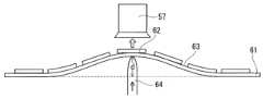
최근, 미소 전기 기계 시스템(Micro Electro Mechanical Systems; 이하, 「MEMS」라고 기재) 등의 미세한 제품의 개구에 대해 보호 커버 부재를 배치하는 요청이 있다. 그 일환으로서, 상기 제품의 제조 공정에 있어서의 보호 커버 부재의 배치의 효율을 향상시키기 위해, 밀어올림에 의해 반도체 소자를 픽업하는 장치를 보호 커버 부재의 픽업에 응용하는 것이 검토되고 있다. 당해 장치에서는, 보호 커버 부재(62)의 배치면(63)과는 반대 측으로부터 밀어올림(push up) 압자(64)에 의해 기재 시트(61)를 밀어올린 상태(이때, 보호 커버 부재(62)는 기재 시트(61)에 대해 부분적으로 박리함)에서, 흡착 노즐(57) 등에 의해 보호 커버 부재(62)를 픽업하는 것이 상정된다(도 1 참조).Recently, there has been a request to place a protective cover member over the opening of microscopic products such as Micro Electro Mechanical Systems (hereinafter referred to as “MEMS”). As part of this, in order to improve the efficiency of arrangement of the protective cover member in the manufacturing process of the product, applying a device for picking up a semiconductor element by pushing to pick up the protective cover member is being considered. In this device, the
특허문헌 1에는, MEMS의 개구를 보호하기 위한 벤트 조립품이며, ePTFE 멤브레인 벤트(통기 필터)와, 점착제에 의해 통기 필터에 설치된 담체를 구비하고, 담체의 하면에 UV 경화성 다이싱 테이프인 라이너(기재 시트)를 첩부한 벤트 조립품이 개시되어 있다. 특허문헌 1에 개시되는 바와 같은 MEMS의 개구를 위한 보호 커버 부재는, 통상 분할된 후에 보호 커버 부재가 되는 부재 시트와 기재 시트를 접합한 상태로 최종 사용자에게 공급된다. 최종 사용자에 의해 부재 시트는 다이싱되며, 바꾸어 말하면 싱귤레이션되어 복수의 보호 커버 부재로 분할된다. 다이싱 후, 기재 시트에 대한 보호 커버 부재의 부분적인 박리를 용이하게 하기 위해서 자외선(UV 광)이 조사된다.
본 발명자들의 검토에 의하면, 특허문헌 1이 개시하는 부재의 공급 방법에 있어서, 부재용 시트(93)에 점착제(92)에 의해 기재 시트(91)를 첩부하고 나서(도 2의 좌측 도면 참조), 보관 등에 의해 장기간이 경과하면, 부재용 시트(93)의 하부와 기재 시트(91)의 점착제(92)와의 계면이 서서히 융화되어 간다(도 2의 우측 도면 참조). 또한, 본 발명자들은 시간의 경과에 따른 상술한 융화됨이 기재 시트의 점착제의 점착력의 증가를 가져와서, 상술한 픽업 장치를 사용하여 기재 시트로부터 보호 커버 부재를 픽업할 때의 픽업성의 불안정화를 초래하는 것을 발견했다.According to the present inventors' examination, in the method of supplying a member disclosed in
본 발명은 보호 커버 부재를 공급하기 위한 부재 공급용 시트의 개량을 목적으로 한다.The purpose of the present invention is to improve a member supply sheet for supplying a protective cover member.
본 발명은This invention
개구를 갖는 면을 가진 대상물의 상기 면에 배치되는 2 이상의 보호 커버 부재와, 상기 2 이상의 보호 커버 부재가 표면에 배치된 기재 시트를 구비한, 상기 보호 커버 부재를 공급하기 위한 부재 공급용 시트이며,A member supply sheet for supplying the protective cover members, comprising two or more protective cover members disposed on the surface of the object having a surface having an opening, and a base sheet with the two or more protective cover members disposed on the surface. ,
상기 보호 커버 부재는, 상기 보호 커버 부재가 상기 면에 배치되었을 때에 상기 개구를 덮는 형상을 갖는 보호막과, 상기 보호막의 주연부에 접합된 담체 필름을 포함하는 적층체로 구성되며,The protective cover member is composed of a laminate including a protective film having a shape that covers the opening when the protective cover member is disposed on the surface, and a carrier film bonded to the periphery of the protective film,
상기 기재 시트는, 기재층과, 상기 기재층에 적층된 점착제층을 포함하고,The base sheet includes a base layer and an adhesive layer laminated on the base layer,
상기 점착제층을 개재시켜 상기 담체 필름이 상기 기재층에 접합되어 있고,The carrier film is bonded to the base layer through the adhesive layer,
상기 담체 필름의 표면 자유 에너지는, 상기 기재 시트 측의 표면에 있어서, 20mJ/㎡ 이상이고,The surface free energy of the carrier film is 20 mJ/m2 or more on the surface of the base sheet side,
상기 점착제층의 태크력은 100mN/mm2 이하인,The tack force of the adhesive layer is 100mN/mm2 or less,
부재 공급용 시트Material supply sheet
를 제공한다.provides.
본 발명의 부재 공급용 시트에서는, 보호 커버 부재에 있어서의 담체 필름의 표면 자유 에너지가, 기재 시트 측의 표면에 있어서, 소정의 값 이상이다. 또한, 기재 시트에 있어서의 점착제층의 태크력이 소정의 값 이하이다. 본 발명자들의 검토에 의하면, 이 부재 공급용 시트는, 점착제층의 태크력이 억제되어 있다. 그 때문에, 밀어올림에 의한 상기 부분적인 박리 및 그 후의 픽업에 있어서의 보호 커버 부재의 최종적인 박리가 원활하고 확실하게 진행된다. 따라서, 본 발명의 부재 공급용 시트에 의하면, 픽업성이 향상된다.In the member supply sheet of the present invention, the surface free energy of the carrier film in the protective cover member is a predetermined value or more on the surface on the base sheet side. Additionally, the tack force of the adhesive layer in the base sheet is below a predetermined value. According to the examination by the present inventors, the tack force of the adhesive layer of this member supply sheet is suppressed. Therefore, the partial peeling by pushing up and the final peeling of the protective cover member during subsequent pickup proceed smoothly and reliably. Therefore, according to the member supply sheet of the present invention, pick-up properties are improved.
도 1은, 밀어올림 픽업 장치에 있어서의 보호 커버 부재의 픽업을 설명하기 위한 모식도이다.
도 2는, 특허문헌 1이 개시하는 부재에 대해서, 시간의 경과에 수반하여 기재 시트의 점착제의 점착력이 증가하는 메커니즘을 도시하는 모식도이다.
도 3a는, 본 발명의 부재 공급용 시트의 일례를 모식적으로 도시하는 평면도이다.
도 3b는, 도 3a의 부재 공급용 시트의 영역(I)에 있어서의 단면 B-B를 도시하는 단면도이다.
도 4는, 본 발명의 부재 공급용 시트에 의한 보호 커버 부재의 공급의 일 양태를 도시하는 모식도이다.
도 5a는, 본 발명의 부재 공급용 시트에 의한 보호 커버 부재의 공급의 일 양태를 설명하기 위한 모식적인 평면도이다.
도 5b는, 도 5a의 단면 B-B를 모식적으로 도시하는 단면도이다.
도 5c는, 픽업 시의 양태를 모식적으로 도시하는 단면도이다.
도 6은, 본 발명의 부재 공급용 시트에 의해 공급되는 보호 커버 부재의 일례를 모식적으로 도시하는 단면도이다.
도 7a는, 본 발명의 부재 공급용 시트에 의해 공급되는 보호 커버 부재의 일례를 모식적으로 도시하는 단면도이다.
도 7b는, 본 발명의 부재 공급용 시트에 의해 공급되는 보호 커버 부재의 일례를 모식적으로 도시하는 단면도이다.
도 8은, 본 발명의 부재 공급용 시트에 의해 공급되는 보호 커버 부재의 일례를 모식적으로 도시하는 평면도이다.
도 9는, 본 발명의 부재 공급용 시트에 의해 공급되는 보호 커버 부재의 일례를 모식적으로 도시하는 단면도이다.
도 10은, 본 발명의 부재 공급용 시트에 의해 공급되는 보호 커버 부재의 일례를 모식적으로 도시하는 단면도이다.
도 11은, 본 발명의 부재 공급용 시트에 의해 공급되는 보호 커버 부재의 일례를 모식적으로 도시하는 단면도이다.
도 12는, 본 발명의 부재 공급용 시트에 의해 공급되는 보호 커버 부재의 일례를 모식적으로 도시하는 단면도이다.
도 13a는, 실시예에서 실시한 부재 공급용 시트에 대한 픽업 특성의 평가 시험을 설명하기 위한 모식적인 평면도이다.
도 13b는, 도 13a의 단면 B-B를 모식적으로 도시하는 단면도이다.
도 13c는, 픽업 시의 양태를 모식적으로 도시하는 단면도이다.
도 14는, 실시예에서 실시한 부재 공급용 시트에 대한 픽업 특성의 평가 시험을 설명하기 위한 모식도이다.
도 15는, 실시예에서 실시한 부재 공급용 시트에 대한 표면 자유 에너지의 산출에 사용하는 그래프이다.
도 16은, 실시예에서 실시한 부재 공급용 시트에 대한 태크력의 평가 시험을 설명하기 위한 모식도이다.
도 17은, 실시예에서 실시한 부재 공급용 시트의 제조 공정의 일부를 도시하는 모식도이다.Fig. 1 is a schematic diagram for explaining pickup of a protective cover member in a push-up pickup device.
FIG. 2 is a schematic diagram showing a mechanism by which the adhesive force of the adhesive of the base sheet increases with time with respect to the member disclosed in
Fig. 3A is a plan view schematically showing an example of the sheet for supplying members of the present invention.
FIG. 3B is a cross-sectional view showing cross section BB in region I of the member supply sheet in FIG. 3A.
Fig. 4 is a schematic diagram showing one mode of supply of a protective cover member using the member supply sheet of the present invention.
Fig. 5A is a schematic plan view for explaining one mode of supply of a protective cover member using the member supply sheet of the present invention.
FIG. 5B is a cross-sectional view schematically showing cross-section BB in FIG. 5A.
Fig. 5C is a cross-sectional view schematically showing the state during pickup.
Fig. 6 is a cross-sectional view schematically showing an example of a protective cover member supplied by the member supply sheet of the present invention.
Fig. 7A is a cross-sectional view schematically showing an example of a protective cover member supplied by the member supply sheet of the present invention.
Fig. 7B is a cross-sectional view schematically showing an example of a protective cover member supplied by the member supply sheet of the present invention.
Fig. 8 is a plan view schematically showing an example of a protective cover member supplied by the member supply sheet of the present invention.
Fig. 9 is a cross-sectional view schematically showing an example of a protective cover member supplied by the member supply sheet of the present invention.
Fig. 10 is a cross-sectional view schematically showing an example of a protective cover member supplied by the member supply sheet of the present invention.
Fig. 11 is a cross-sectional view schematically showing an example of a protective cover member supplied by the member supply sheet of the present invention.
Fig. 12 is a cross-sectional view schematically showing an example of a protective cover member supplied by the member supply sheet of the present invention.
FIG. 13A is a schematic plan view for explaining the evaluation test of the pickup characteristics of the member supply sheet performed in the example.
FIG. 13B is a cross-sectional view schematically showing cross-section BB in FIG. 13A.
Fig. 13C is a cross-sectional view schematically showing the state during pickup.
Figure 14 is a schematic diagram for explaining the evaluation test of the pickup characteristics of the sheet for member supply conducted in the examples.
FIG. 15 is a graph used to calculate the surface free energy for the member supply sheet performed in the examples.
Figure 16 is a schematic diagram for explaining the tack force evaluation test for the member supply sheet performed in the Example.
Fig. 17 is a schematic diagram showing a part of the manufacturing process of the member supply sheet performed in the examples.
이하, 본 발명의 실시 형태에 대해서, 도면을 참조하면서 설명한다. 본 발명은, 이하의 실시 형태로 한정되지는 않는다. EMBODIMENT OF THE INVENTION Hereinafter, embodiment of this invention will be described with reference to the drawings. The present invention is not limited to the following embodiments.
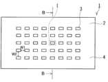
본 발명의 부재 공급용 시트의 일례를 도 3a 및 도 3b에 도시한다. 도 3b에는, 도 3a의 부재 공급용 시트(1)에 있어서의 영역(I)의 단면 B-B가 도시되어 있다. 부재 공급용 시트(1)는, 기재 시트(2)와, 기재 시트(2)의 표면(배치면)(4)에 배치된 2 이상의 보호 커버 부재(3)를 구비한다. 이와 같이 부재 공급용 시트(1)에서는, 기재 시트(2)의 표면(4)에 복수의 보호 커버 부재(3)가 배열되어 있다.An example of the sheet for supplying members of the present invention is shown in FIGS. 3A and 3B. In FIG. 3B, a cross section B-B of region I in the
복수의 보호 커버 부재(3)는, 기재 시트(2)의 표면(4)에 서로 간격(W)을 유지한 상태에서 종횡으로 배열되어 있다. 간격(W)은 0.05mm 이상 또한 5.0mm 이하, 특히 0.10mm 이상 또한 3.0mm 이하여도 된다. 간격(W)은, 다이싱 쏘의 폭보다 커도 되고, 바꾸어 말하면 0.10mm 이상, 또한 3.0mm 이상이어도 된다. 도 3a의 기재 시트(2)는, 직사각형의 형상을 갖는 매엽상이며, 기재 시트(2)의 표면(4)에, 표면(4)에 수직인 방향에서 볼 때 직사각형의 보호 커버 부재(3)가 배열되어 있다. 간격(W)은, 보호 커버 부재(3)의 주면에 수직으로 볼 때, 보호 커버 부재(3)의 긴 변 방향에 있어서의 간격(W1) 및 보호 커버 부재(3)의 짧은 변 방향에 있어서의 간격(W2)을 포함한다. 간격(W1) 및 간격(W2)은, 각각 W에 대해서 상기에 예시한 범위 내에 있어도 된다. 간격(W1) 및 간격(W2)은 동등해도 되고, 상이하여도 된다.A plurality of
부재 공급용 시트(1)는, 보호 커버 부재(3)를 공급하기 위한 시트이다. 보호 커버 부재(3)는, 개구를 갖는 면을 가진 대상물의 당해 면(배치면)에 배치되는 부재이다. 배치면에 대한 보호 커버 부재(3)의 배치에 의해, 예를 들어 상기 개구에의 및/또는 상기 개구로부터의 이물의 침입, 바꾸어 말하면, 상기 개구를 통한 이물의 침입을 방지할 수 있다. 보호 커버 부재(3)는, 개구를 갖는 면을 가진 대상물의 당해 면에 배치되어, 상기 개구에의 이물의 침입을 방지하는 부재여도 된다. 보호 커버 부재(3)는, 보호막(31)과 보호막(31)의 주연부에 접합된 담체 필름(33)을 포함하는 적층체(34)로 구성된다. 보호막(31)은, 보호 커버 부재(3)가 상기 면에 배치되었을 때에 상기 개구를 덮는 형상을 갖는다.The
도 3b의 예에서는, 적층체(34)는 보호막(31), 점착제층(32) 및 담체 필름(33)의 3층 구조를 갖고 있다. 보호막(31)과 점착제층(32)은 서로 접합하고 있다. 점착제층(32)과 담체 필름(33)은 서로 접합하고 있다. 기재 시트(2)는 기재층(21)과, 기재층(21)에 적층된 점착제층(22)을 포함한다. 부재 공급용 시트(1)에서는, 점착제층(22)을 개재시켜 담체 필름(33)이 기재층(21)에 접합되어 있다.In the example of FIG. 3B, the laminate 34 has a three-layer structure of a
적층체(34)는, 보호막(31) 및 담체 필름(33)의 2층 구조여도 된다. 이 경우, 보호막(31)과 담체 필름(33)은 초음파 용착 등의 방법에 의해 용착되어 있어도 된다.The laminate 34 may have a two-layer structure of a
보호 커버 부재(3)에 대해서, 담체 필름(33)의 표면 자유 에너지는, 기재 시트(2) 측의 표면에 있어서, 20mJ/㎡ 이상이다. 담체 필름(33)의 표면 자유 에너지는, 기재 시트(2) 측의 표면에 있어서, 30mJ/㎡ 이상, 40mJ/㎡ 이상, 나아가 50mJ/㎡ 이상이어도 된다. 담체 필름(33)의 표면 자유 에너지의 상한은, 예를 들어 65mJ/㎡ 이하이다.With respect to the
고체의 표면 자유 에너지(즉, 표면 장력)는, 다음과 같이 해서 산출된다.The surface free energy (i.e., surface tension) of a solid is calculated as follows.
표면 장력γ은, 표면 장력γ=분산 에너지 성분γd+극성 에너지 성분γp로 표시된다. 이하에서는, 액체의 표면 장력γ을 γL, 고체의 표면 장력γ을 γS로 나타낸다.The surface tension γ is expressed as surface tension γ = dispersion energy component γd + polar energy component γp . Hereinafter, the surface tension γ of the liquid is expressed as γL and the surface tension γ of the solid is expressed as γS.
표면 장력γ이 기지의 2종의 액체 L(순수, 에틸렌글리콜)에 대해서, 문헌 등으로부터 γL, γLd, γLp를 얻는다. 기지의 2종의 액체 L의 수치를 이하의 표 1에 나타낸다.For two types of liquid L (pure water, ethylene glycol) whose surface tension γ is known, γL , γLd , and γLp are obtained from the literature. The values of the two known liquids L are shown in Table 1 below.
[표 1][Table 1]

상기 2종의 액체 L(순수, 에틸렌글리콜)에 대해서, 자동 접촉각 측정 장치(에코 세이키 제조, Contact Angle System OCA30)를 사용하여 접촉각(θ)을 측정한다.For the above two types of liquid L (pure water, ethylene glycol), the contact angle (θ) is measured using an automatic contact angle measuring device (Contact Angle System OCA30, manufactured by Eco Seiki).
하기의 영-뒤프레(Young-Dupre)의 식과, 표 1에 나타낸 2종의 액체 L의 수치 및 측정된 접촉각(θ)으로부터, 도 15에 도시하는 그래프가 얻어진다. 도 15의 그래프에 있어서, 점 A는 순수를 나타내고, 점 B는 에틸렌글리콜을 나타낸다. 또한, 하기에 있어서, WLS는, 영-뒤프레의 식의 좌변에 상당한다.From the Young-Dupre equation below, the values of the two types of liquid L shown in Table 1, and the measured contact angle (θ), the graph shown in FIG. 15 is obtained. In the graph of Figure 15, point A represents pure water and point B represents ethylene glycol. In addition, in the following, WLS corresponds to the left side of the Young-Dupré equation.
[수학식 1][Equation 1]

도 15에 도시하는 그래프로부터, 절편(γSd)0.5 및 기울기(γSp)0.5를 산출한다. 고체의 표면 장력γS는, 분산 에너지 성분γSd+극성 에너지 성분γSp로 표시되기 때문에, 상기 결과로부터 표면 자유 에너지를 산출할 수 있다.From the graph shown in FIG. 15, an intercept (γSd )of 0.5 and a slope (γSp ) of0.5 are calculated. Since the surface tension γS of a solid is expressed as dispersion energy component γSd + polar energy component γSp , the surface free energy can be calculated from the above results.
기재 시트(2)에 대해서, 점착제층(22)의 태크력은 100mN/mm2 이하이다. 점착제층(22)의 태크력은 90mN/mm2 이하, 나아가 85mN/mm2 이하여도 된다. 점착제층(22)의 태크력의 하한은, 예를 들어 20mN/mm2 이상이다.With respect to the
태크력을 구하기 위한 인장 시험에 대해서, 도 16을 참조하면서 설명한다. 기재 시트(2)의 점착제층(22)이 외측(도 16에 있어서 상측)이 되도록, 기재 시트(2)를 아크릴 양면 테이프(닛토 덴코 제조, No.5000NS)의 한쪽 면과 접합한 후, 15mm×15mm의 정사각형으로 잘라낸다. No.5000NS의 다른 쪽의 면은, SUS304제 받침대에 첩부한다. 인장 시험기(시마즈 세이사쿠쇼 제조, 오토그래프 AGS-X)에 직경 10mm의 SUS304제 원기둥 프로브 P를 세트한다. 시험편에 대해, 25℃에서, 3mm/분의 속도로 5N×15초간, 압축 접착시킨다(압축 모드 M1). 그 후, 25℃에서, 100mm/분의 속도로 인장 시험을 행하고(인장 모드 M2), 이때의 최대 하중을 측정함으로써 태크력을 산출할 수 있다.The tensile test for determining the tack force will be explained with reference to FIG. 16. After bonding the
부재 공급용 시트(1)는, 밀어올림 픽업 장치에 보호 커버 부재(3)를 공급하는 시트로서 사용할 수 있다. 단, 부재 공급용 시트(1)에 의한 보호 커버 부재(3)의 공급처는, 밀어올림 픽업 장치로 한정되지는 않는다. 예를 들어, 밀어올림 픽업 장치 이외의 픽업 장치, 혹은 손이나 핀셋 등에 의해 보호 커버 부재(3)를 픽업해서 사용하는 공정에, 보호 커버 부재(3)를 공급하는 것도 가능하다. 밀어올림 픽업 장치의 예는, 칩 마운터 및 다이 본더이다. 단, 밀어올림 픽업 장치는 상기 예로 한정되지는 않는다.The
도 4에, 밀어올림 픽업 장치에 대한 부재 공급용 시트(1)에 의한 보호 커버 부재(3)의 공급의 예를 나타낸다. 도 4에 도시하는 바와 같이, 밀어올림 픽업 장치에 공급된 부재 공급용 시트(1)는, 보호 커버 부재(3)가 배치된 위치에 있어서, 당해 장치가 구비하는 밀어올림 압자(71)에 의해, 기재 시트(2)의 표면(4)과는 반대 측으로부터 밀어올려진다. 밀어올림에 의해 기재 시트(2)는 상측으로 변형되어, 보호 커버 부재(3)는 기재 시트(2)로부터 부분적으로 박리한다. 박리면은, 보호 커버 부재(3)의 담체 필름(33)과 기재 시트(2)의 점착제층(22)과의 사이에 위치한다. 이 상태에서, 흡착 노즐 등의 픽업부(72)에 의해, 보호 커버 부재(3)가 기재 시트(2)로부터 픽업된다. 픽업된 보호 커버 부재(3)는, 예를 들어 픽업부(72)에 의해 반송되어, 개구(75)를 갖는 면(74)을 가진 대상물(73)의 당해 면(74)에 배치할 수 있다. 보호 커버 부재(3)의 배치는, 예를 들어 담체 필름(33)이 면(74)에 접하도록 실시할 수 있다.Fig. 4 shows an example of supply of the
구체적인 픽업의 양태는, 기재 시트(2)의 밀어올림이 픽업 시에 실시되는 한, 한정되지는 않는다. 픽업의 구체적인 양태의 예를 도 5a부터 도 5c에 도시한다. 또한, 도 5b에는, 도 5a의 단면 B-B가 도시되어 있다. 도 5c에는, 픽업 시의 양태가 모식적으로 도시되어 있다. 도 5a 및 도 5b의 부재 공급용 시트(1)는, 다이싱 링(웨이퍼 링)(42)에 고정된 상태에서 밀어올림 픽업 장치에 공급된다. 도 5a 및 도 5b의 부재 공급용 시트(1)는, 기재 시트(2)의 점착제층(22)에 의해 다이싱 링(42)에 고정되어 있다. 단, 부재 공급용 시트(1)의 고정 방법은, 상기 예로 한정되지는 않는다. 부재 공급용 시트(1)는, 예를 들어 양면 점착 테이프에 의해 다이싱 링(42)에 고정되어 있어도 된다.The specific mode of pickup is not limited as long as the
도 5a의 예에서는, 기재 시트(2) 위에 2 이상의 보호 커버 부재(3)가 규칙적으로 배치되어 있다. 보다 구체적으로는, 보호 커버 부재(3)는, 기재 시트(2)의 표면에 수직으로 볼 때, 각각의 보호 커버 부재(3)의 중심이 장방 격자의 교점(격자점)에 위치하도록 배치되어 있다. 단, 규칙적으로 배치된 보호 커버 부재(3)의 배열은 상기 예로 한정되지는 않는다. 각각의 보호 커버 부재(3)의 중심이, 정방 격자, 사방 격자, 마름모형 격자 등의 다양한 격자의 교점에 위치하도록 규칙적으로 배치되어 있어도 된다. 또한, 보호 커버 부재(3)의 배치의 양태는, 상기 예로 한정되지는 않는다. 예를 들어, 기재 시트(2)의 표면에 수직으로 볼 때, 보호 커버 부재(3)가 지그재그상으로 배치되어 있어도 된다. 또한, 보호 커버 부재(3)의 중심은, 표면에 수직으로 보았을 때의 당해 부재(3)의 형상의 무게 중심으로서 정할 수 있다.In the example of Fig. 5A, two or more
도 5c의 예에서는, 기재 시트(2)의 밀어올림은, 다이싱 링(42)의 내경보다 작은 외경을 갖는 별도의 다이싱 링(익스팬드 링)(46)에 의해, 부재 공급용 시트(1)를 들어 올린 상태에서 실시되고 있다. 밀어올림 압자(47)에 의한 밀어올림 양이 최대에 도달한 시점에서, 흡착 노즐(48)에 의해, 보호 커버 부재(3)가 기재 시트(2)로부터 픽업된다.In the example of FIG. 5C, the
기재 시트(2)에 포함되는 기재층(21)을 구성하는 재료는, 전형적으로는 수지이다. 수지의 예는, 폴리에틸렌 및 폴리프로필렌 등의 폴리올레핀, 폴리염화비닐 및 폴리우레탄이다. 단, 기재층(21)을 구성하는 재료는, 상기 예로 한정되지는 않는다. 기재층(21)은 단층이어도, 2 이상의 층의 적층 구조를 갖고 있어도 된다.The material constituting the
기재층(21)에 적층된 점착제층(22)은, 자외선(UV 광)의 조사에 의해 경화한 자외선 경화형 점착제(UV 경화형 점착제)이다. 바꾸어 말하면, 점착제층(22)은, 기재층(21)에 적층한 UV 경화형 점착제에 UV 광을 조사하고, 경화시킴으로써 형성된다. 점착제층(22)이 UV 광의 조사에 의해 경화한 UV 경화형 점착제이면, 시간의 경과에 의한 태크력의 증가가 억제된다. 이에 따라, 보호 커버 부재(3)의 픽업성이 향상된다.The
기재 시트(2)는, 기재층(21)과 점착제층(22)과의 적층 구조를 갖는 다이싱 테이프여도 된다.The
기재 시트(2)의 두께는, 예를 들어 1 내지 200㎛이다. 기재 시트(2)의 두께는, 100㎛ 이하여도 된다.The thickness of the
도 3a의 기재 시트(2)는, 직사각형의 형상을 갖는 매엽상이다. 도 5a의 기재 시트(2)는, 원의 형상을 갖는 매엽상이다. 매엽상인 기재 시트(2)의 형상은 상기 예로 한정되지는 않고, 정사각형 및 직사각형을 포함한 다각형, 원, 타원 등이어도 된다. 기재 시트(2)가 매엽상일 경우, 부재 공급용 시트(1)는 매엽의 상태에서 유통 및 사용할 수 있다. 기재 시트(2)는 띠상이어도 되고, 이 경우, 부재 공급용 시트(1)도 띠상이 된다. 띠상의 부재 공급용 시트(1)는, 권취 코어에 권회한 권회체로서 유통할 수 있다.The
보호막(31)은, 두께 방향에 비통기성이어도, 두께 방향의 통기성을 갖고 있어도 된다. 보호막(31)이 두께 방향의 통기성을 갖는 경우, 보호 커버 부재(3)의 배치에 의해, 예를 들어 대상물(73)의 개구(75)를 통한 이물의 침입을 방지하면서 개구(75)의 통기성을 확보할 수 있다. 통기성의 확보에 의해, 예를 들어 대상물(73)의 개구(75)를 통한 압력의 조정이나 압력의 변동의 완화가 가능해진다. 압력의 변동을 완화하는 일례를 이하에 나타낸다. 회로 기판에 마련된 관통 구멍의 한쪽의 개구를 덮도록 반도체 소자를 배치한 상태에서, 땜납 리플로 등의 가열 처리를 실시하는 경우가 있다. 여기서, 다른 쪽의 개구를 덮도록 보호 커버 부재(3)를 배치함으로써, 가열 처리 시에 있어서의 관통 구멍을 통한 소자에의 이물의 침입을 억제할 수 있다. 보호막(31)이 두께 방향의 통기성을 가지면, 가열에 의한 관통 구멍 내의 압력 상승이 완화되어, 압력 상승에 의한 소자의 손상을 방지할 수 있다. 반도체 소자의 예는, 마이크로폰, 압력 센서, 가속도 센서 등의 MEMS이다. 이들의 소자는, 통기 또는 통음 가능한 개구를 갖고 있고, 당해 개구가 상기 관통 구멍에 면하도록 회로 기판에 배치할 수 있다. 보호 커버 부재(3)는, 제조 후의 반도체 소자의 개구(75)를 덮도록 당해 소자에 배치되어도 된다. 보호막(31)이 두께 방향의 통기성을 갖는 경우, 배치된 보호 커버 부재(3)는, 예를 들어 개구(75)를 통한 이물의 침입을 방지하면서 당해 개구(75)를 통한 통기성이 확보되는 통기 부재, 및/또는 개구(75)를 통한 이물의 침입을 방지하면서 당해 개구(75)를 통한 통음성이 확보되는 통음 부재로서 기능할 수 있다. 또한, 보호막(31)이 두께 방향에 비통기성일 경우에도, 보호막(31)의 진동에 의한 소리의 전달이 가능하다는 점에서, 배치 후의 보호 커버 부재(3)는 통음 부재로서 기능할 수 있다.The
두께 방향의 통기성을 갖는 보호막(31)의 당해 통기도는, JIS L1096에 정해진 통기성 측정 B법(걸리형법)에 준거해서 구한 공기 투과도(걸리 통기도)에 의해 표시하여, 예를 들어 100초/100mL 이하이다.The air permeability of the
보호막(31)은, 방수성 및/또는 방진성을 갖고 있어도 된다. 방수성을 갖는 보호막(31)을 구비하는 보호 커버 부재(3)는, 대상물(73)에의 배치 후에, 예를 들어 방수 통기 부재 및/또는 방수 통음 부재로서 기능할 수 있다. 방수성을 갖는 보호막(31)의 내수압은, JIS L1092에 정해진 내수도 시험 A법(저수압법) 또는 B법(고수압법)에 준거해서 구한 값으로 해서, 예를 들어 5kPa 이상이다.The
보호막(31)을 구성하는 재료의 예는, 금속, 수지 및 이들 복합 재료이다.Examples of materials constituting the
보호막(31)을 구성할 수 있는 수지의 예는, 폴리에틸렌, 폴리프로필렌 등의 폴리올레핀, 폴리에틸렌테레프탈레이트(PET) 등의 폴리에스테르, 실리콘 수지, 폴리카르보네이트, 폴리이미드, 폴리아미드이미드, 폴리페닐렌술피드, 폴리에테르에테르케톤(PEEK), 불소 수지이다. 불소 수지의 예는, 폴리테트라플루오로에틸렌(PTFE), 테트라플루오로에틸렌-퍼플루오로알킬비닐에테르 공중합체(PFA), 테트라플루오로에틸렌-헥사플루오로프로필렌 공중합체(FEP), 테트라플루오로에틸렌-에틸렌 공중합체(ETFE)이다. 단, 수지는 상기 예로 한정되지는 않는다.Examples of resins that can form the
보호막(31)을 구성할 수 있는 금속의 예는, 스테인리스 및 알루미늄이다.Examples of metals that can form the
보호막(31)은, 내열성 재료로 구성되어도 된다. 이 경우, 보호 커버 부재(3)를 구성하는 다른 층의 재료에 따라서는, 땜납 리플로 등의 고온 하에서의 처리에 대해 보다 확실한 대응이 가능하다. 내열성 재료의 예는, 금속 및 내열성 수지이다. 내열성 수지는, 전형적으로는 150℃ 이상의 융점을 갖는다. 내열성 수지의 융점은, 160℃ 이상, 200℃ 이상, 250℃ 이상, 260℃ 이상, 나아가 300℃ 이상이어도 된다. 내열성 수지의 예는, 실리콘 수지, 폴리이미드, 폴리아미드이미드, 폴리페닐렌술피드, PEEK 및 불소 수지이다. 불소 수지는 PTFE여도 된다. PTFE는 내열성이 특히 우수하다.The
두께 방향의 통기성을 갖는 보호막(31)은, 연신 다공질막을 포함하고 있어도 된다. 연신 다공질막은, 불소 수지의 연신 다공질막, 특히 PTFE 연신 다공질막이어도 된다. PTFE 연신 다공질막은, 통상 PTFE 입자를 포함하는 페이스트 압출물 또는 캐스트막을 연신해서 형성된다. PTFE 연신 다공질막은, PTFE의 미세한 피브릴에 의해 구성되고, 피브릴에 비하여 PTFE가 응집한 상태에 있는 노드를 갖는 경우도 있다. PTFE 연신 다공질막에 의하면, 이물의 침입을 방지하는 성능 및 통기성을 높은 레벨에서 양립시키는 것이 가능하다. 보호막(31)에는, 공지된 연신 다공질막을 사용할 수 있다.The
두께 방향의 통기성을 갖는 보호막(31)은, 양쪽의 주면을 접속하는 복수의 관통 구멍이 형성된 천공막을 포함하고 있어도 된다. 천공막은, 비다공질의 기질 구조를 갖는 원막, 예를 들어 무공막에 복수의 관통 구멍이 형성된 막이어도 된다. 천공막은, 상기 복수의 관통 구멍 이외에, 두께 방향의 통기 경로를 갖고 있지 않아도 된다. 관통 구멍은, 천공막의 두께 방향으로 연장되어 있어도 되고, 두께 방향에 직선상으로 연장되는 스트레이트 구멍이어도 된다. 관통 구멍의 개구의 형상은, 천공막의 주면에 수직으로 볼 때, 원 또는 타원이어도 된다. 천공막은, 예를 들어 원막에 대한 레이저 가공, 또는 이온 빔 조사 및 이것으로 이어지는 화학 에칭에 의한 펀칭 가공에 의해 형성할 수 있다.The
두께 방향의 통기성을 갖는 보호막(31)은 부직포, 직포, 메시, 네트를 포함하고 있어도 된다.The
보호막(31)은, 상기 예로 한정되지는 않는다.The
도 3b의 보호막(31)의 형상은, 그의 주면에 수직으로 볼 때, 직사각형이다. 단, 보호막(31)의 형상은 상기 예로 한정되지는 않고, 예를 들어 그 주면에 수직으로 볼 때, 정사각형 및 직사각형을 포함한 다각형, 원, 타원이어도 된다. 다각형은 정다각형이어도 된다. 다각형의 각은, 둥글게 되어 있어도 된다.The shape of the
보호막(31)의 두께는, 예를 들어 1 내지 100㎛이다.The thickness of the
보호막(31)의 면적은, 예를 들어 175mm2 이하이다. 보호막(31)의 면적이 당해 범위에 있는 보호 커버 부재(3)는, 예를 들어 소경의 개구를 통상 갖는 회로 기판이나 MEMS에의 배치에 적합하다. 보호막(31)의 면적의 하한은, 예를 들어 0.20mm2 이상이다. 단, 보호막(31)의 면적은, 보호 커버 부재(3)가 배치되는 대상물의 종류에 따라서는 더 커도 된다.The area of the
점착제층(32)은, 예를 들어 점착제의 도포층이다. 점착제의 예는, 아크릴계 점착제, 실리콘계 점착제, 우레탄계 점착제, 에폭시계 점착제 및 고무계 점착제이다. 고온 하에서의 보호 커버 부재(3)의 사용을 고려할 필요가 있는 경우에는, 내열성이 우수한 아크릴계 점착제 또는 실리콘계 점착제, 특히 아크릴계 점착제를 선택하는 것이 바람직하다.The
아크릴계 점착제는, 예를 들어 일본 특허 공개 제2005-105212호 공보에 개시된 점착제이다. 실리콘계 점착제는, 예를 들어 일본 특허 공개 제2003-313516호 공보에 개시된 점착제(비교예로서 개시된 것을 포함함)이다.The acrylic adhesive is, for example, an adhesive disclosed in Japanese Patent Application Laid-Open No. 2005-105212. The silicone-based adhesive is, for example, an adhesive disclosed in Japanese Patent Application Laid-Open No. 2003-313516 (including those disclosed as comparative examples).
점착제층(32)은 단층이어도, 2 이상의 점착제층을 포함하는 적층 구조를 갖고 있어도 된다.The
도 3b의 점착제층(32)은 보호막(31)과 접합하고 있다. 단, 보호막(31)과 점착제층(32)과의 사이에 다른 층이 배치되어 있어도 된다.The
점착제층(32)은, 양면 점착 테이프여도 된다(도 6 참조). 도 6의 점착제층(32)은, 기재(32A)와, 기재(32A)의 양쪽의 면에 마련된 점착제층(32B)을 갖는 기재 함유 테이프이다. 한 쌍의 점착제층(32B)에 포함되는 점착제는, 서로 동일하여도 상이하여도 된다. 예를 들어, 한쪽의 점착제층(32B)이 아크릴계 점착제를 포함하고, 다른 쪽의 점착제층(32B)이 실리콘계 점착제를 포함하고 있어도 된다. 양면 점착 테이프는, 기재(32A)를 포함하지 않는 무(無) 기재 테이프여도 된다.The
점착제층(32)은, 복수의 점착제층의 조합이어도 된다. 점착제층(32)은, 기재(32A)와, 기재(32A)의 편면에 마련된 점착제층(32B)을 갖는 편면 점착 테이프와, 점착제층(32C)이 조합된 적층 구조체여도 된다(도 7a 및 도 7b 참조). 도 8a의 예에서는, 편면 점착 테이프의 점착제층(32B)이, 담체 필름(33)의 표면과의 접합면이 된다. 도 7b의 예에서는, 점착제층(32C)이, 담체 필름(33)의 표면과의 접합면이 된다. 점착제층(32C)은 점착제의 도포층이어도, 양면 점착 테이프여도 된다.The
점착제층(32)에 있어서의 담체 필름(33)의 표면과의 접합면은, 아크릴계 점착제에 의해 구성되어 있는 것이 바람직하다.The bonding surface of the
점착 테이프의 기재(32A)는, 예를 들어 수지, 금속 또는 이들 복합 재료의 필름, 부직포 또는 폼이다. 점착 테이프의 기재(32A)는, 내열성 재료로 구성되어도 된다. 이 경우, 보호 커버 부재(3)를 구성하는 다른 층의 재료에 따라서는, 고온 하에서의 사용에 대해 보다 확실한 대응이 가능하다. 내열성 재료의 구체예는, 보호막(31)의 설명에 있어서 상술한 바와 같다.The
점착제층(32)의 두께는, 예를 들어 10 내지 200㎛이다.The thickness of the
담체 필름(33)은 비점착성의 필름이다. 담체 필름(33)은, 예를 들어 수지 필름, 부직포, 종이, 금속박, 직포, 고무 시트, 발포 시트, 이들의 적층체이다. 수지 필름은, 예를 들어 폴리이미드(PI), 폴리불화비닐리덴(PVdF), 폴리에테르술폰(PES) 및 폴리페닐렌술피드(PPS)로 이루어지는 군에서 선택되는 적어도 1종을 포함하고 있어도 된다.The
도 3b의 담체 필름(33)은 점착제층(32)과 접합하고 있다. 단, 담체 필름(33)과 점착제층(32) 사이에 다른 층이 배치되어 있어도 된다.The
담체 필름(33)의 두께는, 예를 들어 10 내지 200㎛이다.The thickness of the
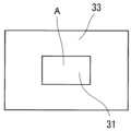
도 3b의 점착제층(32) 및 담체 필름(33)은, 보호막(31)의 주면에 수직으로 볼 때, 당해 주면 위의 제한된 영역에 배치되어 있다. 도 3b의 점착제층(32) 및 담체 필름(33)의 형상은, 보호막(31)의 주면에 수직으로 볼 때, 보호막(31)의 주연부의 형상이며, 보다 구체적으로는, 프레임상이다(도 8 참조). 또한, 도 8은, 도 3a 및 도 3b의 보호 커버 부재(3)를 담체 필름(33)의 측으로부터 본 평면도이다. 이 경우, 점착제층(32) 및 담체 필름(33)이 형성되어 있지 않은 보호막(11)의 영역 A에 있어서, 점착제층(32) 및 담체 필름(33)이 형성되어 있는 영역과 비교해서 양호한 통기 및/또는 통음이 가능해진다. 단, 점착제층(32) 및 담체 필름(33)의 형상은 상기 예로 한정되지는 않는다.The
보호막(11)의 영역 A의 면적은, 예를 들어 20mm2 이하이다. 영역 A의 면적이 당해 범위에 있는 보호 커버 부재(3)는, 예를 들어 소경의 개구를 통상 갖는 회로 기판이나 MEMS에의 배치에 적합하다. 영역 A의 면적의 하한은, 예를 들어 0.008mm2 이상이다. 단, 영역 A의 면적은, 보호 커버 부재(3)가 배치되는 대상물(73)의 종류에 따라서는, 보다 큰 범위여도 된다.The area of region A of the protective film 11 is, for example, 20 mm2 or less. The
보호 커버 부재(3)의 적층체(34)는, 보호막(31), 점착제층(32) 및 담체 필름(33) 이외의 층을 구비하고 있어도 된다. 추가적인 층을 구비하는 보호 커버 부재(3)의 예를 도 9 내지 도 12에 도시한다.The
도 9의 적층체(34)는, 점착제층(32)과 함께 보호막(31)을 끼움 지지하는 위치에 배치된 점착제층(35)을 구비한다. 이 경우, 점착제층(35) 위에 추가적인 층의 배치가 가능하게 되거나, 보호 커버 부재(3)의 대상물(73)에의 배치 시에, 점착제층(35)을 임의의 부재 및/또는 표면 등에 접합시키거나 할 수 있다. 점착제층(32)이 아닌 점착제층(35)이 대상물(73)의 면(74)에 접하도록, 보호 커버 부재(3)를 배치해도 된다. 도 9의 점착제층(35)은 보호막(31)과 접합하고 있다. 단, 보호막(31)과 점착제층(35) 사이에 다른 층이 배치되어 있어도 된다. 도 9의 보호 커버 부재(3)는, 점착제층(35)을 더 구비하는 것 이외에는, 도 3b의 보호 커버 부재(3)와 동일하다.The laminate 34 in FIG. 9 includes an
점착제층(35)은, 점착제층(32)과 마찬가지의 구성을 가질 수 있다. 예를 들어, 점착제층(35)은, 양면 점착 테이프여도 된다(도 10 참조). 도 10의 점착제층(35)은, 기재(35A)와, 기재(35A)의 양쪽의 면에 마련된 점착제층(35B)을 갖는 기재 함유 테이프이다.The
도 9 및 도 10의 점착제층(35)의 형상은, 점착제층(32)의 형상과 동일하다. 이 경우, 점착제층(35)이 형성되어 있지 않은 보호막(11)의 영역 B에 있어서, 점착제층(35)이 형성되어 있는 영역과 비교해서 양호한 통기 및/또는 통음이 가능해진다. 단, 점착제층(35)의 형상은 상기 예로 한정되지는 않는다. 영역 B의 면적은, 영역 A의 면적과 동일한 범위를 취할 수 있다. 영역 B의 면적은, 영역 A의 면적과 동일해도 된다.The shape of the
도 11의 적층체(34)는, 보호막(31)에 대해 점착제층(32) 및 담체 필름(33)과는 반대 측에 위치함과 함께, 보호막(31)을 덮는 커버 필름(36)을 더 구비한다. 커버 필름(36)은, 점착제층(35) 위에 배치되어 있다. 점착제층(35)과 커버 필름(36) 사이에 다른 층이 배치되어 있어도 된다. 커버 필름(36)은, 예를 들어 대상물(73)에 보호 커버 부재(3)가 배치될 때까지의 사이에 보호막(31)을 보호하는 보호 필름으로서 기능한다. 대상물(73)에의 배치 후에 커버 필름(36)을 박리해도 된다. 커버 필름(36)은 보호막(31)의 주면에 수직으로 볼 때, 보호막(31)의 전체를 덮고 있어도, 일부를 덮고 있어도 된다.The laminate 34 in FIG. 11 is located on the opposite side of the
도 11의 커버 필름(36)은, 보호막(31)의 주면에 수직으로 볼 때, 보호막(31)의 외주보다 외측으로 돌출된 부분인 탭(37)을 갖는다. 탭(37)은, 커버 필름(36)의 박리에 이용 가능하다. 단, 커버 필름(36)의 형상은, 상기 예로 한정되지는 않는다.The
커버 필름(36)을 구성하는 재료의 예는, 금속, 수지 및 이들의 복합 재료이다. 커버 필름(36)을 구성할 수 있는 재료의 구체예는, 기재(32A)를 구성할 수 있는 재료의 구체예와 동일하다.Examples of materials constituting the
커버 필름(36)의 두께는, 예를 들어 200 내지 1000㎛이다.The thickness of the
커버 필름(36)을 더 구비하는 보호 커버 부재(3)의 별도의 일례를 도 12에 도시한다. 도 12의 보호 커버 부재(3)는, 점착제층(32) 및 점착제층(35)이 양면 점착 테이프인 것 이외에는, 도 11의 보호 커버 부재(3)와 동일하다.Another example of the
도 3a 및 도 3b의 보호 커버 부재(3)의 형상은, 보호막(31)의 주면에 수직으로 볼 때, 직사각형이다. 단, 보호 커버 부재(3)의 형상은, 상기 예로 한정되지는 않는다. 형상은, 보호막(31)의 주면에 수직으로 볼 때, 정사각형 및 직사각형을 포함한 다각형, 원, 타원이어도 된다. 다각형은, 정다각형이어도 된다. 다각형의 각은, 둥글게 되어 있어도 된다.The shape of the
보호 커버 부재(3)의 면적(보호막(31)의 주면에 수직으로 보았을 때의 면적)은, 예를 들어 175mm2 이하이다. 면적이 당해 범위에 있는 보호 커버 부재(3)는, 예를 들어 소경의 개구를 통상 갖는 회로 기판이나 MEMS에의 배치에 적합하다. 보호 커버 부재(3)의 면적의 하한은, 예를 들어 0.20mm2 이상이다. 단, 보호 커버 부재(3)의 면적은, 배치되는 대상물의 종류에 따라서는, 보다 큰 값이어도 된다. 또한, 보호 커버 부재(3)의 면적이 작을수록 픽업이 어려워진다. 이 때문에, 보호 커버 부재(3)의 면적이 상기 범위에 있을 경우에, 본 발명의 효과는 특히 현저해진다.The area of the protective cover member 3 (area when viewed perpendicular to the main surface of the protective film 31) is, for example, 175 mm2 or less. The
보호 커버 부재(3)를 배치하는 대상물(73)은, 예를 들어 MEMS 등의 반도체 소자, 회로 기판이다. 바꾸어 말하면, 보호 커버 부재(3)는, 반도체 소자, 회로 기판 또는 MEMS를 대상물(73)로 하는 반도체 소자용, 회로 기판용 또는 MEMS용 부재여도 된다. MEMS는, 패키지의 표면에 통기 구멍을 갖는 비밀폐계의 소자여도 된다. 비밀폐계 MEMS의 예는, 기압, 습도, 가스, 공기 흐름 등을 검출하는 각종 센서 및 스피커나 마이크로폰 등의 전기 음향 변환 소자이다. 또한, 대상물(73)은, 제조 후의 반도체 소자나 회로 기판으로 한정되지는 않고, 제조 공정에 있는 이들의 소자나 기판의 중간 제조물이어도 된다. 이 경우, 보호 커버 부재(3)에 의해, 제조 공정에 있어서의 중간 제조물의 보호가 가능해진다. 제조 공정의 예는, 땜납 리플로 공정, 다이싱 공정, 본딩 공정, 실장 공정이다. 단, 대상물(73)은, 상기 예로 한정되지는 않는다.The
보호 커버 부재(3)가 배치될 수 있는 대상물(73)의 면(74)은, 전형적으로는 대상물(73)의 표면이다. 면(74)은, 평면이어도 곡면이어도 된다. 또한, 대상물(73)의 개구(75)는 오목부의 개구여도, 관통 구멍의 개구여도 된다.The
부재 공급용 시트(1)에 의해, 보호 커버 부재(3)가 면(74)에 배치된 대상물(73)의 제조가 가능해진다. 본 개시는, 부재 공급용 시트(1)를 공급하여 보호 커버 부재가 구비된 대상물을 제조하는 방법을 포함한다. 부재 공급용 시트(1)의 공급처는, 전형적으로는 밀어올림 픽업 장치이다.The
부재 공급용 시트(1)는, 기재 시트(2)의 표면(4)에 보호 커버 부재(3)를 배치해서 제조할 수 있다. 보호 커버 부재(3)는, 예를 들어 보호막(31), 점착제층(32) 및 담체 필름(33)의 적층에 의해 제조할 수 있다. 기재 시트(2)는, 예를 들어 기재층(21) 및 점착제층(22)의 적층에 의해 제조할 수 있다. 부재 공급용 시트(1)는, 예를 들어 점착제층(22)을 개재시켜 담체 필름(33)을 기재층(21)에 접합함으로써 제조할 수 있다.The
부재 공급용 시트(1)는, 곤포재에 의해 곤포된 상태로 최종 사용자에게 공급된다. 부재 공급용 시트(1)는, UV 광의 조사에 의해 경화한 UV 경화형 점착제인 점착제층(22)을 가지며, 또한 보호 커버 부재가 서로 0.05mm 이상 또한 5.0mm 이하의 간격(W)으로 배열된 상태로, 곤포재에 의해 곤포되어 있어도 된다.The
[실시예][Example]
이하, 실시예에 의해 본 발명을 더욱 상세하게 설명한다. 본 발명은 이하에 나타내는 실시예로 한정되지는 않는다.Hereinafter, the present invention will be described in more detail through examples. The present invention is not limited to the examples shown below.
먼저, 기재 시트의 특성, 부재 공급용 시트에 있어서의 보호 커버 부재의 픽업 특성 및 제품 어긋남의 평가 방법을 기재한다.First, the characteristics of the base sheet, the pickup characteristics of the protective cover member in the member supply sheet, and the evaluation method for product deviation are described.
[표면 자유 에너지][Surface free energy]
보호 커버 부재에 있어서의 담체 필름의 표면 자유 에너지는, 상술한 방법에 의해 산출한 표면 장력γ으로부터 산출했다.The surface free energy of the carrier film in the protective cover member was calculated from the surface tension γ calculated by the method described above.
[태크력][Tackling power]
기재 시트에 있어서의 점착제층의 태크력은, 상술한 방법에 의해 산출했다.The tack force of the adhesive layer in the base sheet was calculated by the method described above.
[픽업 특성][Pickup characteristics]
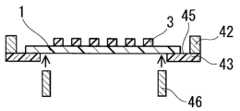
부재 공급용 시트의 픽업 특성은, 이하와 같이 평가했다. 밀어올림 픽업 장치(다이토론 제조, 웨이퍼 칩 소터 WCS-700C)의 마운터 상에, 제작한 부재 공급용 시트를 배치했다. 마운터는 4개의 밀어올림 압자를 구비하고 있었다. 밀어올림 압자는, 직경 0.15mm의 니들상이며, 선단의 곡률이 0.022mm, 높이가 0.20mm였다. 프로그램에 따라, 기재 시트 위의 개개의 보호 커버 부재를 임의의 밀어올림 양 및 밀어올림 속도로 밀어올릴 수 있다. 부재 공급용 시트는, 다이싱 링(42)을 사용하여, 다음과 같이 배치했다(도 13a 및 도 13b 참조. 또한, 도 13b에는, 도 13a의 단면 B-B가 도시되어 있음). 다이싱 링(42)의 한쪽 면에, 서로의 외주를 일치시켜서 편면 점착 시트(43)를 첩부했다. 편면 점착 시트(43)의 중앙부에는, 당해 시트(43)의 주면에 수직으로 볼 때 직사각형(100mm×60mm)의 개구(44)를 마련해 두었다. 이어서, 평가 대상인 부재 공급용 시트(1)를, 개구(44)를 덮도록 편면 점착 시트(43)의 점착면(45)에 세트하고, 다이싱 링(42)에 고정했다. 세트는, 부재 공급용 시트(1) 및 개구(44)의 긴 변이 서로 평행해지도록, 또한 부재 공급용 시트(1)의 외주와 개구(44)의 외주와의 거리가 양쪽의 외주 전체에 걸쳐 균일해지도록 실시했다. 다음으로, 부재 공급용 시트(1)를 고정한 다이싱 링(42)을 마운터 상에 배치했다.The pickup characteristics of the sheet for member supply were evaluated as follows. The fabricated member supply sheet was placed on the mounter of a push pickup device (wafer chip sorter WCS-700C, manufactured by Daitoron). The mounter was equipped with four push indenters. The push indenter was needle-shaped with a diameter of 0.15 mm, the curvature of the tip was 0.022 mm, and the height was 0.20 mm. Depending on the program, individual protective cover members on the base sheet can be pushed up at any push-up amount and push-up speed. The member supply sheet was arranged as follows using the dicing ring 42 (see FIGS. 13A and 13B. In addition, in FIG. 13B, the cross section B-B of FIG. 13A is shown). A single-
다음으로, 1개의 부재 공급용 시트 상에 배치된 100개의 보호 커버 부재 중, 랜덤하게 선택한 10개의 보호 커버 부재를 1세트로 하고, 당해 세트에 포함되는 보호 커버 부재에 대해 하나씩 순서대로, 밀어올림에 의한 픽업을 시도했다. 밀어올림 양은 200㎛로 했다. 밀어올림 속도는 4.0mm/초로 했다. 밀어올림은, 상기 4개의 밀어올림 압자에 의해, 정사각형의 보호 커버 부재(3)에 있어서, 점 39a, 39b, 39c, 39d를 밀어올려 실시했다. 점 39a, 39b, 39c, 39d는 각각 보호막(31)의 대(對)정점 및 기재 시트(3)의 대정점을 통과하는 2개의 대각선(38A, 38B) 위에 있어서의 보호막(31)의 꼭짓점과 이것에 대응하는 기재 시트(3)의 꼭짓점과의 중심점이다(도 14 참조). 또한, 밀어올림은, 부재 공급용 시트를 고정한 다이싱 링(42)의 내경보다 작은 외경을 갖는 별도의 다이싱 링(익스팬드 링)(46)에 의해, 편면 점착 시트(43) 및 부재 공급용 시트(1)를 2.0mm 들어 올린 상태(확장 높이 2.0mm)에서 실시했다(도 13c 참조. 또한, 도 13c에는, 픽업 시의 양태가 모식적으로 도시되어 있음). 또한, 다이싱 링(46)에는, 부재 공급용 시트(1)의 주면에 수직으로 볼 때, 보호 커버 부재(3)와 중복되지 않는 것을 선택했다. 픽업에는 흡착 노즐(48)을 사용하여, 밀어올림 양이 최대에 도달한 시점에서 흡착 노즐(48)에 의한 흡착을 스타트시켰다. 흡착 노즐(48)의 직경은 0.5mm이며, 흡인 압력은 45kPa로 했다. 흡착 시간은 100m초로 했다. 1세트에 포함되는 보호 커버 부재의 개수 A(10개)와, 픽업된 당해 세트 중 보호 커버 부재의 개수 B와의 비인 픽업률 B/A에 의해, 픽업 특성을 평가했다. 픽업률 B/A가 9/10 이상인 경우를 합격○, 그 이외를 불합격×으로 판정했다.Next, among the 100 protective cover members arranged on one member supply sheet, 10 randomly selected protective cover members are set as one set, and each protective cover member included in the set is pushed up, one by one. Pickup was attempted by . The amount of push-up was set to 200 μm. The pushing speed was set at 4.0 mm/sec. The pushing was performed by pushing up
[제품 어긋남][Product misalignment]
부재 공급용 시트의 제품 어긋남은, 이하와 같이 평가했다. 10개의 보호 커버 부재가 배치된 부재 공급용 시트에 대해서, 복합 환경 진동 시험기(IMV 제조, VS-5500-220T)를 사용하여, JIS Z0232에 기재된 방법에 따라 진동 시험을 행했다. 주파수 범위는 5 내지 200Hz, 진동 방향은 z축(수직) 방향, 가속도는 5.8m/s2, 진동 시간은 180분으로 했다. 진동 시험 후, 초기의 상태로부터, 기재 시트에 대해 보호 커버 부재가, 수평 방향으로 0.10mm 이상 어긋난 경우를 불합격×, 수평 방향의 어긋남 폭이 0.10mm 미만인 경우를 합격○으로 판정했다.Product deviation of the member supply sheet was evaluated as follows. A vibration test was performed on the member supply sheet on which 10 protective cover members were arranged according to the method described in JIS Z0232 using a composite environmental vibration tester (VS-5500-220T, manufactured by IMV). The frequency range was 5 to 200 Hz, the vibration direction was z-axis (vertical), the acceleration was 5.8 m/s2 , and the vibration time was 180 minutes. After the vibration test, from the initial state, the case where the protective cover member was shifted by more than 0.10 mm in the horizontal direction with respect to the base sheet was judged to be failed x, and the case where the width of the horizontal shift was less than 0.10 mm was judged to be pass ○.
(제조예 1: 보호 커버 부재 A의 제작)(Manufacturing Example 1: Production of protective cover member A)
보호막(31)으로서, PTFE 다공질막(닛토 덴코 제조, NTF1033, 두께 10㎛)을 준비했다. PTFE 다공질막의 형상은, 외형 3.0mm×3.0mm의 정사각형으로 했다. 이어서, 보호막(31)의 한쪽의 주면에, 점착제층(32)으로서, 프레임상의 형상을 갖는 내열 양면 점착 테이프(닛토 덴코 제조, No.585)를 접합했다. 점착제층(32)의 외형은 3.0mm×3.0mm의 정사각형, 내형은 1.5mm×1.5mm의 정사각형, 폭은 전체 둘레에 걸쳐 일정했다. 또한, 담체 필름(33)으로서, 폴리이미드 필름(도레이·듀퐁 제조, 캡톤 200H, 표면 자유 에너지 53.3mJ/㎡)을 내열 양면 점착 테이프와 동 형상이 되도록 준비했다. 보호막(31), 점착제층(32) 및 담체 필름(33)은, 그의 외주가 일치하도록 접합했다. 양면 점착 테이프의 점착제층(32B)은 양면 모두 아크릴계 점착제층이었다. 이와 같이 하여, 보호막(31)의 주면에서 볼 때 정사각형인 보호 커버 부재 A를 얻었다.As the
(제조예 2: 보호 커버 부재 B1 내지 B3의 제작)(Manufacture Example 2: Production of protective cover members B1 to B3)
담체 필름(33)으로서, 3종의 내열 필름을 사용한 것 이외에는, 제조예 1과 마찬가지로 하여, 보호 커버 부재 B1 내지 B3을 얻었다. 보호 커버 부재 B1에는, 담체 필름(33)으로서, 불화비닐리덴 필름(구레하 익스트론 제조, KFC 필름 FT-50Y, 표면 자유 에너지 34.1mJ/㎡)을 사용했다. 보호 커버 부재 B2에는, 담체 필름(33)으로서, 폴리에테르술폰 필름(스미토모 베이크라이트 제조, 스미라이트 FS-1300, 표면 자유 에너지 51.5mJ/㎡)을 사용했다. 보호 커버 부재 B3에는, 담체 필름(33)으로서, 폴리페닐렌술피드 필름(도레이 제조, 토렐리나#50-3030, 표면 자유 에너지 64.5mJ/㎡)을 사용했다. Protective cover members B1 to B3 were obtained in the same manner as in Production Example 1, except that three types of heat-resistant films were used as the
(제조예 3: 보호 커버 부재 C의 제작)(Manufacture Example 3: Production of protective cover member C)
담체 필름(33)으로서, 폴리테트라플루오로에틸렌 필름(닛토 덴코 제조, 니토플론 No.900UL, 표면 자유 에너지 18.0mJ/㎡)을 사용한 것 이외에는, 제조예 1과 마찬가지로 하여, 보호 커버 부재 C를 얻었다.As the
(기재 시트)(list sheet)
기재 시트(2)로서, 5종의 다이싱 테이프 a 내지 e(닛토 덴코 제조, 엘렙 홀더)를 준비했다. 다이싱 테이프 a 내지 e의 제품명 및 특성을 표 2에 나타낸다. 다이싱 테이프 a 내지 e의 형상은, 직경 270mm의 원형으로 했다.As the
[표 2][Table 2]

(실시예 1)(Example 1)
다이싱 링(이즈미 메탈 제조, 8인치 플랫 링)에, 점착제층(22)을 상면으로 하여 다이싱 테이프 a를 접합했다. 다음으로, 다이싱 테이프 a의 점착제층(22)에, 보호 커버 부재 A를 100개(10열×10행) 배치해서 접합했다. 배치는, 다이싱 테이프 a에 있어서의 보호 커버 부재 A의 배치면에 수직으로 볼 때, 각 보호 커버 부재 A가 서로 0.10mm 이상 또한 0.50mm 이하의 간격(W)을 유지한 상태로 배열되도록 실시했다. 상기 접합 1시간 후에, PET 기재를 포함하는 세퍼레이터를 보호 커버 부재 A에 씌우고 나서, UV 조사 장치(닛토 세이키 제조, UM810)를 사용하여, 300mJ/cm2의 적산 광량이 되도록, 다이싱 테이프 a의 기재층(21) 측으로부터 UV 광을 7초간 조사했다. 이와 같이 하여, 실시예 1의 부재 공급용 시트를 얻었다.Dicing tape a was bonded to a dicing ring (8-inch flat ring manufactured by Izumi Metal) with the
도 17은, 부재 공급용 시트(1)의 제조 공정의 일부를 도시하는 모식도이다. 도 17에서는, 설명을 용이하게 하기 위해, 보호 커버 부재(3)에 있어서의 보호막(31) 및 점착제층(32)은 생략되어 있다. 기재층(21)에, 점착제층(22)을 구성하는 UV 경화형 점착제를 개재시켜 담체 필름(33)을 접합한 후(도 17의 좌측 도면 참조), 상기 조건으로 UV 광을 조사하면, 점착제층(22)을 구성하는 점착제가 경화 및 수축하고, 점착제의 유동성이 억제된다(도 17의 우측 도면 참조). 즉, 부재 공급용 시트(1)는, UV 광 조사에 의해 경화한 UV 경화형 점착제인 점착제층(22)을 갖는다. 그 때문에, 담체 필름(33)과 점착제와의 친화성이 높아도, 시간의 경과에 의한 점착제의 태크력의 증가가 억제된다.Fig. 17 is a schematic diagram showing a part of the manufacturing process of the
(실시예 2)(Example 2)
기재 시트(2)로서, 다이싱 테이프 b를 사용한 것 이외에는 실시예 1과 마찬가지로 하여, 실시예 2의 부재 공급용 시트를 얻었다.As the
(실시예 3)(Example 3)
기재 시트(2)로서, 다이싱 테이프 c를 사용한 것 이외에는 실시예 1과 마찬가지로 하여, 실시예 2의 부재 공급용 시트를 얻었다.As the
(실시예 4)(Example 4)
기재 시트(2)로서, 다이싱 테이프 d를 사용한 것 이외에는 실시예 1과 마찬가지로 하여, 실시예 2의 부재 공급용 시트를 얻었다.As the
(실시예 5)(Example 5)
보호 커버 부재(3)로서, 보호 커버 부재 B1을 사용한 것 이외에는 실시예 1과 마찬가지로 하여, 실시예 5의 부재 공급용 시트를 얻었다.As the
(실시예 6)(Example 6)
보호 커버 부재(3)로서, 보호 커버 부재 B2를 사용한 것 이외에는 실시예 1과 마찬가지로 하여, 실시예 6의 부재 공급용 시트를 얻었다.As the
(실시예 7)(Example 7)
보호 커버 부재(3)로서, 보호 커버 부재 B3을 사용한 것 이외에는 실시예 1과 마찬가지로 하여, 실시예 7의 부재 공급용 시트를 얻었다.As the
(비교예 1)(Comparative Example 1)
상기 접합 후, 85℃ 또한 95% RH의 환경 하에서 24시간 보관한 후에, 상기 조건으로 UV 광을 조사한 것 이외에는 실시예 1과 마찬가지로 하여, 비교예 1의 부재 공급용 시트를 얻었다.After the bonding, the sheet was stored for 24 hours at 85°C and 95% RH, and then irradiated with UV light under the above conditions, in the same manner as in Example 1, to obtain a sheet for supplying components of Comparative Example 1.
(비교예 2)(Comparative Example 2)
상기 접합 후, 85℃ 또한 95% RH의 환경 하에서 24시간 보관한 후에, 상기 조건으로 UV 광을 조사한 것 이외에는 실시예 2와 마찬가지로 하여, 비교예 2의 부재 공급용 시트를 얻었다.After the above bonding, the sheet for component supply of Comparative Example 2 was obtained in the same manner as in Example 2 except that it was stored in an environment of 85°C and 95% RH for 24 hours, and then UV light was irradiated under the above conditions.
(비교예 3)(Comparative Example 3)
상기 접합 후, 85℃ 또한 95% RH의 환경 하에서 24시간 보관한 후에, 상기 조건으로 UV 광을 조사한 것 이외에는 실시예 3과 마찬가지로 하여, 비교예 3의 부재 공급용 시트를 얻었다.After the bonding, the sheet was stored for 24 hours at 85°C and 95% RH, and then irradiated with UV light under the above conditions, in the same manner as in Example 3, to obtain a sheet for supplying components of Comparative Example 3.
(비교예 4)(Comparative Example 4)
상기 접합 후, 85℃ 또한 95% RH의 환경 하에서 24시간 보관한 후에, 상기 조건으로 UV 광을 조사한 것 이외에는 실시예 4와 마찬가지로 하여, 비교예 4의 부재 공급용 시트를 얻었다.After the above bonding, the sheet for component supply of Comparative Example 4 was obtained in the same manner as in Example 4, except that the product was stored in an environment of 85°C and 95% RH for 24 hours and irradiated with UV light under the above conditions.
(비교예 5)(Comparative Example 5)
기재 시트(2)로서, 다이싱 테이프 e를 사용한 것 이외에는 비교예 1과 마찬가지로 하여 비교예 5의 부재 공급용 시트를 얻었다.As the
(비교예 6)(Comparative Example 6)
보호 커버 부재(3)로서, 보호 커버 부재 C를 사용한 것 이외에는 실시예 1과 마찬가지로 하여, 비교예 6의 부재 공급용 시트를 얻었다.As the
평가 결과를 이하의 표 3A 및 표 3B에 나타낸다.The evaluation results are shown in Tables 3A and 3B below.
[표 3A][Table 3A]

[표 3B][Table 3B]

표 3A 및 표 3B에 나타내는 바와 같이, 실시예 1 내지 7에서는, 양호한 픽업성을 확보할 수 있으며, 또한 제품 어긋남도 발생하지 않았다.As shown in Tables 3A and 3B, in Examples 1 to 7, good pick-up properties could be ensured, and product deviation did not occur.
다음으로, 실시예 1 내지 3에 대해서, 상기 접합 3시간 후에, 상기 조건으로 UV 광을 조사해서 픽업 특성을 평가했다. 실시예 1의 픽업률 B/A는 10/10이며, 우수한 픽업성을 유지했다. 실시예 2 및 실시예 3의 픽업률 B/A는, 모두 9/10이었다. 이들의 결과로부터, UV 광을 조사하기 전의 (초기)태크력이 작으면 작을수록, 픽업성이 향상되어 있는 것을 알 수 있다. 즉, UV 광을 조사하기 전의 (초기)태크력은, UV 광을 조사한 후의 태크력에 영향을 주고 있는 것으로 생각된다. 그 메커니즘은 명확하지 않으나, 이하와 같다고 추정된다. UV 광을 조사하기 전의 태크력이 크면, UV 광을 조사해도 태크력이 충분히 저하되지 않는 경우가 있다. 이 경우, UV 광을 조사한 후의 점착력도 크기 때문에, 픽업성이 저하된다고 생각된다. 또한, UV 광 조사 시에 있어서의 점착제층(22)의 경화 및 수축도가 크면 클수록, 피착체인 담체 필름(33)과 점착제층(22)과의 접촉 면적이 감소하고, 점착력은 저하된다. 따라서, UV 광을 조사하기 전의 태크력이 크면, UV 광 조사 시에 발생하는 점착제층(22)의 경화 및 수축이 억제되므로, 담체 필름(33)과 점착제층(22)과의 접착 면적이 감소하기 어려워진다. 이 경우, UV 광 조사에 의한 점착력의 저하가 억제되기 때문에, 픽업성이 저하된다고 생각된다.Next, for Examples 1 to 3, 3 hours after the above bonding, UV light was irradiated under the above conditions to evaluate the pickup characteristics. The pickup rate B/A of Example 1 was 10/10, and excellent pickup properties were maintained. The pickup rates B/A of Examples 2 and 3 were both 9/10. From these results, it can be seen that the smaller the (initial) tack force before irradiation of UV light, the improved the pickup performance. In other words, it is thought that the (initial) tack force before irradiation of UV light affects the tack force after irradiation of UV light. The mechanism is not clear, but is presumed to be as follows. If the tack force before irradiation of UV light is large, the tack force may not be sufficiently reduced even if irradiation of UV light is applied. In this case, since the adhesive force after irradiation of UV light is also large, it is thought that the pick-up performance deteriorates. Additionally, the greater the degree of curing and shrinkage of the
UV 광을 조사하기 전의 부재 공급용 시트에 있어서의 태크력 및 점착력은, UV 광을 조사한 후의 부재 공급용 시트에 기초하여, 점착제층(22)을 구성하는 UV 경화형 점착제에 관한 정성 및 정량 분석(모노머 종류 및 각 성분량), 기재 조성 정보를 사용하여 유추하는 것이 가능하다.The tack force and adhesive force in the member supply sheet before irradiation with UV light were analyzed qualitatively and quantitatively regarding the UV curable adhesive constituting the
본 발명의 부재 공급용 시트는, 예를 들어 밀어올림 픽업 장치에 대한 보호 커버 부재의 공급에 사용할 수 있다.The sheet for supplying members of the present invention can be used, for example, for supplying protective cover members to a push-up pickup device.
Claims (9)
Translated fromKorean상기 보호 커버 부재는, 상기 보호 커버 부재가 상기 면에 배치되었을 때에 상기 개구를 덮는 형상을 갖는 보호막과, 상기 보호막의 주연부에 접합된 담체 필름을 포함하는 적층체로 구성되며,
상기 기재 시트는, 기재층과, 상기 기재층에 적층된 점착제층을 포함하고,
상기 점착제층을 개재시켜 상기 담체 필름이 상기 기재층에 접합되어 있고,
상기 담체 필름의 표면 자유 에너지는, 상기 기재 시트 측의 표면에 있어서, 20mJ/㎡ 이상이고,
상기 점착제층의 태크력은 100mN/mm2 이하인
부재 공급용 시트.A member supply sheet for supplying the protective cover members, comprising two or more protective cover members disposed on the surface of the object having a surface having an opening, and a base sheet with the two or more protective cover members disposed on the surface. ,
The protective cover member is composed of a laminate including a protective film having a shape that covers the opening when the protective cover member is disposed on the surface, and a carrier film bonded to the periphery of the protective film,
The base sheet includes a base layer and an adhesive layer laminated on the base layer,
The carrier film is bonded to the base layer through the adhesive layer,
The surface free energy of the carrier film is 20 mJ/m2 or more on the surface of the base sheet side,
The tack force of the adhesive layer is 100mN/mm2 or less.
Sheet for material supply.
Applications Claiming Priority (3)
| Application Number | Priority Date | Filing Date | Title |
|---|---|---|---|
| JPJP-P-2021-062854 | 2021-04-01 | ||
| JP2021062854AJP7634410B2 (en) | 2021-04-01 | 2021-04-01 | Material supply sheet |
| PCT/JP2022/014709WO2022210435A1 (en) | 2021-04-01 | 2022-03-25 | Sheet for supplying member |
Publications (1)
| Publication Number | Publication Date |
|---|---|
| KR20230166108Atrue KR20230166108A (en) | 2023-12-06 |
Family
ID=83456160
Family Applications (1)
| Application Number | Title | Priority Date | Filing Date |
|---|---|---|---|
| KR1020237037102APendingKR20230166108A (en) | 2021-04-01 | 2022-03-25 | Material supply sheet |
Country Status (7)
| Country | Link |
|---|---|
| US (1) | US20240173947A1 (en) |
| JP (1) | JP7634410B2 (en) |
| KR (1) | KR20230166108A (en) |
| CN (1) | CN117121163A (en) |
| DE (1) | DE112022000882T5 (en) |
| TW (1) | TW202246055A (en) |
| WO (1) | WO2022210435A1 (en) |
Families Citing this family (2)
| Publication number | Priority date | Publication date | Assignee | Title |
|---|---|---|---|---|
| EP4412494A4 (en)* | 2021-10-04 | 2025-08-06 | Greenwood Marketing Llc | FILTER LABEL FOR INFECTION CONTROL |
| WO2025072114A1 (en)* | 2023-09-25 | 2025-04-03 | W. L. Gore & Associates, Inc. | Improved sheet for the production of improved vent assemblies |
Citations (1)
| Publication number | Priority date | Publication date | Assignee | Title |
|---|---|---|---|---|
| JP2018501972A (en) | 2014-12-15 | 2018-01-25 | ダブリュ.エル.ゴア アンド アソシエイツ,インコーポレイティドW.L. Gore & Associates, Incorporated | Vent mounting system for microelectromechanical systems |
Family Cites Families (7)
| Publication number | Priority date | Publication date | Assignee | Title |
|---|---|---|---|---|
| JP3888679B2 (en) | 2002-04-23 | 2007-03-07 | 日東電工株式会社 | Double-sided adhesive tape and fixing method |
| JP4646508B2 (en) | 2003-10-01 | 2011-03-09 | 日東電工株式会社 | Double-sided adhesive tape or sheet and method for producing the same |
| JP4774999B2 (en) | 2006-01-18 | 2011-09-21 | ソニー株式会社 | Manufacturing method of semiconductor device |
| JP2008303386A (en) | 2007-05-08 | 2008-12-18 | Hitachi Chem Co Ltd | Adhesive sheet, method for producing the same, method for producing semiconductor device using the adhesive sheet, and the semiconductor device |
| JPWO2011089664A1 (en) | 2010-01-20 | 2013-05-20 | 住友ベークライト株式会社 | Semiconductor protective film forming film and semiconductor device |
| JP6774301B2 (en) | 2015-11-04 | 2020-10-21 | リンテック株式会社 | Thermosetting resin film and first protective film forming sheet |
| CN114174068B (en) | 2019-07-12 | 2024-09-10 | 日东电工株式会社 | Protective cover member and member supply sheet having the same |
- 2021
- 2021-04-01JPJP2021062854Apatent/JP7634410B2/enactiveActive
- 2022
- 2022-03-25KRKR1020237037102Apatent/KR20230166108A/enactivePending
- 2022-03-25DEDE112022000882.2Tpatent/DE112022000882T5/enactivePending
- 2022-03-25WOPCT/JP2022/014709patent/WO2022210435A1/ennot_activeCeased
- 2022-03-25USUS18/284,401patent/US20240173947A1/enactivePending
- 2022-03-25CNCN202280024569.4Apatent/CN117121163A/enactivePending
- 2022-03-31TWTW111112397Apatent/TW202246055A/enunknown
Patent Citations (1)
| Publication number | Priority date | Publication date | Assignee | Title |
|---|---|---|---|---|
| JP2018501972A (en) | 2014-12-15 | 2018-01-25 | ダブリュ.エル.ゴア アンド アソシエイツ,インコーポレイティドW.L. Gore & Associates, Incorporated | Vent mounting system for microelectromechanical systems |
Also Published As
| Publication number | Publication date |
|---|---|
| JP2022158153A (en) | 2022-10-17 |
| US20240173947A1 (en) | 2024-05-30 |
| TW202246055A (en) | 2022-12-01 |
| DE112022000882T5 (en) | 2023-11-23 |
| JP7634410B2 (en) | 2025-02-21 |
| WO2022210435A1 (en) | 2022-10-06 |
| CN117121163A (en) | 2023-11-24 |
Similar Documents
| Publication | Publication Date | Title |
|---|---|---|
| KR20230166108A (en) | Material supply sheet | |
| CN114761102B (en) | Polytetrafluoroethylene stretched porous film, and air-permeable filter material and filter member using same | |
| CN114174068B (en) | Protective cover member and member supply sheet having the same | |
| CN113226752B (en) | Breathable adhesive sheet and breathable product | |
| CN109715387B (en) | Laminates and Wounds | |
| US12304716B2 (en) | Cover member and member supply assembly including same | |
| JP7514823B2 (en) | MEMBER FOR VENTILATION HOLE, METHOD FOR MANUFACTURING ELECTRONIC DEVICE HAVING MEMBER FOR VENTILATION HOLE, AND MEMBER SUPPLY TAPE | |
| US12214575B2 (en) | Member supplying sheet | |
| US20240286389A1 (en) | Protective cover member, sheet for member supply, and microelectromechanical system | |
| CN115279855A (en) | Protective cover member and member supply sheet |
Legal Events
| Date | Code | Title | Description |
|---|---|---|---|
| PA0105 | International application | Patent event date:20231027 Patent event code:PA01051R01D Comment text:International Patent Application | |
| PG1501 | Laying open of application | ||
| A201 | Request for examination | ||
| PA0201 | Request for examination | Patent event code:PA02012R01D Patent event date:20250123 Comment text:Request for Examination of Application |