KR20230163759A - Biometric information measuring device - Google Patents
Biometric information measuring deviceDownload PDFInfo
- Publication number
- KR20230163759A KR20230163759AKR1020220063458AKR20220063458AKR20230163759AKR 20230163759 AKR20230163759 AKR 20230163759AKR 1020220063458 AKR1020220063458 AKR 1020220063458AKR 20220063458 AKR20220063458 AKR 20220063458AKR 20230163759 AKR20230163759 AKR 20230163759A
- Authority
- KR
- South Korea
- Prior art keywords
- ear
- user
- electrode
- wing
- earlobe
- Prior art date
- Legal status (The legal status is an assumption and is not a legal conclusion. Google has not performed a legal analysis and makes no representation as to the accuracy of the status listed.)
- Pending
Links
- 238000005259measurementMethods0.000claimsabstractdescription58
- QVGXLLKOCUKJST-UHFFFAOYSA-Natomic oxygenChemical compound[O]QVGXLLKOCUKJST-UHFFFAOYSA-N0.000claimsabstractdescription41
- 239000008280bloodSubstances0.000claimsabstractdescription41
- 210000004369bloodAnatomy0.000claimsabstractdescription41
- 229910052760oxygenInorganic materials0.000claimsabstractdescription41
- 239000001301oxygenSubstances0.000claimsabstractdescription41
- 210000000624ear auricleAnatomy0.000claimsabstractdescription40
- 210000000613ear canalAnatomy0.000claimsabstractdescription33
- 210000001061foreheadAnatomy0.000claimsdescription12
- 229920001940conductive polymerPolymers0.000claimsdescription6
- 210000003128headAnatomy0.000claimsdescription6
- 239000004020conductorSubstances0.000claimsdescription4
- 239000011810insulating materialSubstances0.000claimsdescription3
- 239000002861polymer materialSubstances0.000claimsdescription3
- 238000000537electroencephalographyMethods0.000abstract1
- 230000007958sleepEffects0.000description28
- 239000000463materialSubstances0.000description16
- 229920001971elastomerPolymers0.000description12
- 238000012545processingMethods0.000description11
- 238000000034methodMethods0.000description10
- 210000004556brainAnatomy0.000description8
- 238000010586diagramMethods0.000description7
- 208000019116sleep diseaseDiseases0.000description7
- 230000008667sleep stageEffects0.000description6
- 238000012544monitoring processMethods0.000description5
- 229920000642polymerPolymers0.000description5
- 229920001296polysiloxanePolymers0.000description5
- 230000008569processEffects0.000description5
- 239000000806elastomerSubstances0.000description4
- 201000002859sleep apneaDiseases0.000description4
- 230000002618waking effectEffects0.000description4
- 238000004891communicationMethods0.000description2
- 230000005494condensationEffects0.000description2
- 238000009833condensationMethods0.000description2
- 210000005069earsAnatomy0.000description2
- 230000006870functionEffects0.000description2
- 230000001939inductive effectEffects0.000description2
- 230000003287optical effectEffects0.000description2
- 230000000638stimulationEffects0.000description2
- 206010041235SnoringDiseases0.000description1
- 101001045744Sus scrofa Hepatocyte nuclear factor 1-betaProteins0.000description1
- 238000005452bendingMethods0.000description1
- 230000015572biosynthetic processEffects0.000description1
- 238000004590computer programMethods0.000description1
- 238000012937correctionMethods0.000description1
- 238000013461designMethods0.000description1
- 238000001514detection methodMethods0.000description1
- 238000011161developmentMethods0.000description1
- 230000018109developmental processEffects0.000description1
- 239000013013elastic materialSubstances0.000description1
- 230000036541healthEffects0.000description1
- 230000002452interceptive effectEffects0.000description1
- 239000002184metalSubstances0.000description1
- 239000007769metal materialSubstances0.000description1
- 238000012986modificationMethods0.000description1
- 230000004048modificationEffects0.000description1
- 230000036385rapid eye movement (rem) sleepEffects0.000description1
- 230000004044responseEffects0.000description1
- 230000035939shockEffects0.000description1
- 239000002344surface layerSubstances0.000description1
Images


Classifications
- A—HUMAN NECESSITIES
- A61—MEDICAL OR VETERINARY SCIENCE; HYGIENE
- A61B—DIAGNOSIS; SURGERY; IDENTIFICATION
- A61B5/00—Measuring for diagnostic purposes; Identification of persons
- A61B5/48—Other medical applications
- A61B5/4806—Sleep evaluation
- A—HUMAN NECESSITIES
- A61—MEDICAL OR VETERINARY SCIENCE; HYGIENE
- A61B—DIAGNOSIS; SURGERY; IDENTIFICATION
- A61B5/00—Measuring for diagnostic purposes; Identification of persons
- A—HUMAN NECESSITIES
- A61—MEDICAL OR VETERINARY SCIENCE; HYGIENE
- A61B—DIAGNOSIS; SURGERY; IDENTIFICATION
- A61B5/00—Measuring for diagnostic purposes; Identification of persons
- A61B5/145—Measuring characteristics of blood in vivo, e.g. gas concentration or pH-value ; Measuring characteristics of body fluids or tissues, e.g. interstitial fluid or cerebral tissue
- A61B5/1455—Measuring characteristics of blood in vivo, e.g. gas concentration or pH-value ; Measuring characteristics of body fluids or tissues, e.g. interstitial fluid or cerebral tissue using optical sensors, e.g. spectral photometrical oximeters
- A61B5/14551—Measuring characteristics of blood in vivo, e.g. gas concentration or pH-value ; Measuring characteristics of body fluids or tissues, e.g. interstitial fluid or cerebral tissue using optical sensors, e.g. spectral photometrical oximeters for measuring blood gases
- A—HUMAN NECESSITIES
- A61—MEDICAL OR VETERINARY SCIENCE; HYGIENE
- A61B—DIAGNOSIS; SURGERY; IDENTIFICATION
- A61B5/00—Measuring for diagnostic purposes; Identification of persons
- A61B5/24—Detecting, measuring or recording bioelectric or biomagnetic signals of the body or parts thereof
- A61B5/316—Modalities, i.e. specific diagnostic methods
- A61B5/369—Electroencephalography [EEG]
- A61B5/372—Analysis of electroencephalograms
- A—HUMAN NECESSITIES
- A61—MEDICAL OR VETERINARY SCIENCE; HYGIENE
- A61B—DIAGNOSIS; SURGERY; IDENTIFICATION
- A61B5/00—Measuring for diagnostic purposes; Identification of persons
- A61B5/68—Arrangements of detecting, measuring or recording means, e.g. sensors, in relation to patient
- A61B5/6801—Arrangements of detecting, measuring or recording means, e.g. sensors, in relation to patient specially adapted to be attached to or worn on the body surface
- A61B5/6813—Specially adapted to be attached to a specific body part
- A61B5/6814—Head
- A61B5/6815—Ear
- A61B5/6816—Ear lobe
- A—HUMAN NECESSITIES
- A61—MEDICAL OR VETERINARY SCIENCE; HYGIENE
- A61B—DIAGNOSIS; SURGERY; IDENTIFICATION
- A61B5/00—Measuring for diagnostic purposes; Identification of persons
- A61B5/68—Arrangements of detecting, measuring or recording means, e.g. sensors, in relation to patient
- A61B5/6801—Arrangements of detecting, measuring or recording means, e.g. sensors, in relation to patient specially adapted to be attached to or worn on the body surface
- A61B5/6813—Specially adapted to be attached to a specific body part
- A61B5/6814—Head
- A61B5/6815—Ear
- A61B5/6817—Ear canal
- A—HUMAN NECESSITIES
- A61—MEDICAL OR VETERINARY SCIENCE; HYGIENE
- A61B—DIAGNOSIS; SURGERY; IDENTIFICATION
- A61B5/00—Measuring for diagnostic purposes; Identification of persons
- A61B5/68—Arrangements of detecting, measuring or recording means, e.g. sensors, in relation to patient
- A61B5/6801—Arrangements of detecting, measuring or recording means, e.g. sensors, in relation to patient specially adapted to be attached to or worn on the body surface
- A61B5/683—Means for maintaining contact with the body
Landscapes
- Health & Medical Sciences (AREA)
- Life Sciences & Earth Sciences (AREA)
- Physics & Mathematics (AREA)
- Surgery (AREA)
- General Health & Medical Sciences (AREA)
- Engineering & Computer Science (AREA)
- Biomedical Technology (AREA)
- Heart & Thoracic Surgery (AREA)
- Medical Informatics (AREA)
- Molecular Biology (AREA)
- Biophysics (AREA)
- Animal Behavior & Ethology (AREA)
- Pathology (AREA)
- Public Health (AREA)
- Veterinary Medicine (AREA)
- Otolaryngology (AREA)
- Spectroscopy & Molecular Physics (AREA)
- Optics & Photonics (AREA)
- Psychiatry (AREA)
- Psychology (AREA)
- Measurement Of The Respiration, Hearing Ability, Form, And Blood Characteristics Of Living Organisms (AREA)
Abstract
Description
Translated fromKorean의료기기, 헬스케어 기기, 웨어러블 전자 기기에 관련되며, 보다 특정하게는 생체정보 측정 장치에 연관된다.It is related to medical devices, healthcare devices, wearable electronic devices, and more specifically, biometric information measurement devices.
수면은 인간의 건강과 삶의 질에 큰 영향을 미치는 것으로 알려져 있다. 수면의 양 뿐만 아니라 수면의 질도 중요하다. 이러한 수면의 질에는 잠을 잘 드는 것(입면), 잘 자고, 잘 깨는 것(출면)이 모두 영향을 미친다. 사람의 수면의 질은 뇌전도(electroencephalogram: EEG)를 측정함으로써 확인되는 뇌파로 모니터링이 가능하며, 코골이나 수면 무호흡과 같은 수면 장애 현상은 수면 중 혈중산소포화도(SpO2)를 측정하는 것으로 모니터링이 가능하다.Sleep is known to have a significant impact on human health and quality of life. Not only the quantity of sleep but also the quality of sleep is important. Falling asleep well (dysnap), sleeping well, and waking up well (dysnap) all affect the quality of sleep. The quality of a person's sleep can be monitored using brain waves confirmed by measuring an electroencephalogram (EEG), and sleep disorders such as snoring or sleep apnea can be monitored by measuring blood oxygen saturation (SpO2) during sleep. .
종전의 뇌전도 측정은 사람의 머리, 이를테면 이마에 여러 개의 전극을 붙여 전위차를 측정함으로써 전기적 신호의 파형을 확인하는 방식이 주를 이루었으며 대부분 착용의 어려움이나 기구적인 복잡함으로 헬스케어 영역 보다는 전문 의료기기의 영역에서 더 많이 구현되었다. 일부 헬스케어 영역에서 사용자 스스로 착용하는 웨어러블 기기 형태도 소개되어 왔으나, 구조의 복잡성이나 전극 배치의 비효율성 등의 한계가 있었다.Previous electroencephalogram measurement was mainly done by attaching several electrodes to a person's head, such as the forehead, and measuring the potential difference to check the waveform of the electrical signal. In most cases, it was a professional medical device rather than a medical device in the healthcare field due to difficulty in wearing or mechanical complexity. has been implemented more in the area of . Wearable devices that users wear themselves have been introduced in some healthcare areas, but they have limitations such as structural complexity or inefficiency in electrode placement.
혈중산소포화도(SpO2) 측정을 통한 수면무호흡 등 수면 장애가 사용자의 뇌파(EEG)와 함께 측정되어 사용자의 수면 상태를 모니터링 하는 장치가 제공된다. EEG 측정을 위한 기준전극이 장치에 적절한 위치에 포함되어, EEG 전극의 신호 측정의 안정성을 높이고, 노이즈에 강한 장치를 제시한다.A device is provided that monitors the user's sleep status by measuring sleep disorders such as sleep apnea through blood oxygen saturation (SpO2) measurement along with the user's brain waves (EEG). The reference electrode for EEG measurement is included in the device at an appropriate location, increasing the stability of signal measurement of the EEG electrode and presenting a device that is resistant to noise.
또한 EEG 측정에 사용되는 신호 전극이 사용자의 피부와 전기적 접촉을 안정적으로 유지하도록 하는 전극의 위치와 배치가 제시된다.Additionally, the location and arrangement of the signal electrodes used for EEG measurement are presented to ensure stable electrical contact with the user's skin.
기존의 EEG 측정장치들에 비해 구조적으로 단순하면서도, 착용한 사용자가 잠을 자는 동안 뒤척일 때도 전극의 전기적 접촉이 안정적으로 유지됨으로써 EEG 측정에 실패할 확률이 낮게 한다. 나아가 EEG 및 SpO2 모니터링을 통해 사용자의 뇌파에 따라 적절한 사운드 자극 및/또는 음성 가이던스를 주어 입면을 돕고, 수면 중 수면 레벨을 모니터링 한다.Although it is structurally simpler than existing EEG measurement devices, the electrical contact of the electrodes is maintained stably even when the wearer tosses and turns while sleeping, lowering the probability of EEG measurement failure. Furthermore, through EEG and SpO2 monitoring, appropriate sound stimulation and/or voice guidance is provided according to the user's brain waves to help the user fall asleep and monitor the sleep level during sleep.
사용자의 수면 상태와 수면 장애를 모니터링 함으로써, 잠에서 깰 때(출면 시) 수면 단계를 적절히 유도하여 상쾌한 출면을 도울 수 있는 장치가 제시된다. 이러한 장치에 의해 사용자의 수면의 질을 높이는 데에 기여한다.By monitoring the user's sleep status and sleep disorders, a device is presented that can help the user to wake up refreshed by appropriately inducing the sleep stage when waking up (when going out of bed). These devices contribute to improving the user's quality of sleep.
일측에 따르면, 이어버드(earbud type) 전자 장치가 제공된다. 일실시예에 따른 전자 장치는: 사용자의 귓볼(lobule or lobe)을 감싸 고정되면서 상기 귓볼에 매달려 상기 사용자의 혈중산소포화도(SpO2)를 측정하는 혈중산소포화도 측정부 - 상기 혈중산소포화도 측정부는 상기 사용자의 귓볼에 접촉하는 적어도 하나의 기준 전극을 포함함 -; 상기 사용자의 외이도(ear canal) 경부에 삽입되어 상기 외이도 내 피부 상에 접하는 적어도 하나의 인이어(in-ear) 전극을 갖는 이어팁(ear tip); 상기 이어팁을 상기 외이도 내측으로 밀어 지지하며, 상기 사용자의 귓바퀴(antihelix) 내측에 끼워져 고정되는 윙 구조의 탄성구조를 갖는 이어윙(ear wing); 및 상기 적어도 하나의 인이어 전극과 상기 적어도 하나의 기준 전극 사이의 전위차에 기초하여 상기 사용자의 뇌전도(electroencephalogram: EEG)를 측정하는 EEG 측정부를 포함한다.According to one side, an earbud type electronic device is provided. The electronic device according to one embodiment includes: a blood oxygen saturation measuring unit that is fixed around the user's earlobe (lobule or lobe) and hangs from the earlobe to measure the user's blood oxygen saturation (SpO2) - the blood oxygen saturation measuring unit comprising at least one reference electrode contacting the user's earlobe; An ear tip having at least one in-ear electrode that is inserted into the neck of the user's ear canal and comes into contact with the skin within the external auditory canal; An ear wing that pushes and supports the ear tip inside the external auditory canal and has an elastic structure of a wing structure that is inserted and fixed inside the user's ear (antihelix); and an EEG measurement unit that measures the user's electroencephalogram (EEG) based on a potential difference between the at least one in-ear electrode and the at least one reference electrode.
일실시예에 따르면, 상기 이어윙은 상기 윙 구조가 상기 사용자의 상기 귓바퀴 내측에 접하는 면에 적어도 하나의 이어윙 전극을 더 포함할 수 있다. 이 때, 상기 EEG 측정부는 상기 적어도 하나의 이어윙 전극 및 상기 적어도 하나의 기준 전극 사이의 전위차에 기초하여 상기 뇌전도를 측정할 수 있다.According to one embodiment, the ear wing may further include at least one ear wing electrode on a surface of the wing structure that contacts the inside of the user's ear flap. At this time, the EEG measurement unit may measure the electroencephalogram based on a potential difference between the at least one ear wing electrode and the at least one reference electrode.
예시적으로, 그러나 한정되지 않게, 상기 윙 구조는 루프 형태이다. 일실시예에 따르면, 상기 윙 구조는 복수의 슬릿을 포함하여 다른 부분보다 상대적으로 높은 유연성 및/또는 신축성을 갖는 탄성구조를 포한다. 유연성 및/또는 신축성이 높다는 것은 외력 - 이를테면 응축력이나 뒤틀리는 힘 -에 의해 윙 구조 내의 다른 부분보다 더 많이 변형되었다가 외력이 약해지면 다시 복원되는 탄성을 갖는 것을 의미한다. 상기 윙 구조는 엘라스토머(elastomer), 고무(rubber), 실리콘 기타 폴리머(중합체) 등의 소재에서 선택되는 것일 수 있으며, 윙 구조에 부분적으로 포함되는 탄성구조는 윙 다른 부분과 형태적으로 구별되도록 가공 또는 성형되어 있으나 소재에 있어서는 동일할 수 있다. 물론 소재에 차이가 있는 경우도 가능하다. 여기서 상기 탄성구조는 외력에 의해 변형되어 상기 윙 구조가 상기 귓바퀴 내측으로 들어가도록 하고, 상기 외력이 상대적으로 약해지는 경우 상기 윙 구조를 복원하여 상기 윙 구조가 상기 귓바퀴 내측에 끼워져 지지되도록 하면서 상기 적어도 하나의 이어윙 전극이 상기 접하는 면에 밀착되도록 한다. 따라서 상기 이어윙 전극이 사용자의 귓바퀴 내측 피부에 밀착되는 것을 돕고, 따라서 EEG 신호의 측정을 위한 전기적인 접촉에 유리하다.By way of example, but not limitation, the wing structure is in the form of a loop. According to one embodiment, the wing structure includes a plurality of slits and includes an elastic structure having relatively higher flexibility and/or elasticity than other parts. High flexibility and/or elasticity means that it is deformed more than other parts of the wing structure by an external force - such as condensation force or twisting force - and has the elasticity to be restored when the external force weakens. The wing structure may be selected from materials such as elastomer, rubber, silicone, and other polymers, and the elastic structure partially included in the wing structure is processed to be morphologically distinct from other parts of the wing. Alternatively, it may be molded but the material may be the same. Of course, it is possible that there are differences in materials. Here, the elastic structure is deformed by an external force so that the wing structure enters the inside of the auricle, and when the external force becomes relatively weak, the wing structure is restored so that the wing structure is fit and supported inside the auricle, and the at least Ensure that one ear wing electrode is in close contact with the contact surface. Therefore, the ear wing electrode helps to adhere closely to the skin inside the user's ear, and is therefore advantageous for electrical contact for measuring EEG signals.
일실시예에 따르면, 상기 혈중산소포화도 측정부는, 혈중산소포화도를 측정하는 센서를 포함하는 제1 파트, 자석을 포함하는 제2 파트, 상기 제1 파트와 상기 제2 파트를 연결하는 유연성 브릿지를 포함한다. 이 실시예에서 상기 제1 파트와 상기 제2 파트는 상기 귓볼을 사이에 두고 상기 자석에 의한 자기적 인력에 의해 상기 귓볼의 양쪽 면에서 서로 대향하면서 상기 귓볼에 매달릴 수 있다. 일실시예에 따르면, 상기 적어도 하나의 기준 전극은 상기 제1 파트 및 상기 제2 파트 중 적어도 하나에 배치되어 상기 귓볼에 접한다.According to one embodiment, the blood oxygen saturation measurement unit includes a first part including a sensor for measuring blood oxygen saturation, a second part including a magnet, and a flexible bridge connecting the first part and the second part. Includes. In this embodiment, the first part and the second part may be suspended from the earlobe while opposing each other on both sides of the earlobe by magnetic attraction caused by the magnet with the earlobe in between. According to one embodiment, the at least one reference electrode is disposed on at least one of the first part and the second part and contacts the earlobe.
한편, 다른 실시예에 따르면, 상기 혈중산소포화도 측정부는, 혈중산소포화도를 측정하는 센서를 포함하는 제1 파트, 상기 기준 전극을 포함하는 제2 파트, 상기 제1 파트와 상기 제2 파트를 연결하는 'U'형(shaped) 커브를 갖는 탄성 브릿지를 포함한다. 이 때 상기 제1 파트와 상기 제2 파트는 상기 귓볼을 사이에 두고 상기 탄성 브릿지의 탄력에 의해 상기 귓볼의 양쪽 면에서 서로 대향하면서 상기 귓볼에 매달릴 수 있다.Meanwhile, according to another embodiment, the blood oxygen saturation measuring unit includes a first part including a sensor for measuring blood oxygen saturation, a second part including the reference electrode, and connecting the first part and the second part. It includes an elastic bridge having a 'U' shaped curve. At this time, the first part and the second part may hang on the earlobe while opposing each other on both sides of the earlobe by the elasticity of the elastic bridge with the earlobe in between.
한편 인이어 전극과 관련하여 일실시예에 따르면, 상기 적어도 하나의 인이어 전극은 절연성 물질로 구성되는 상기 이어팁의 표면 상에 인쇄된 전도성 소재의 전극을 포함한다. 다른 일실시예에 따르면, 상기 이어팁은 상기 EEG 측정부와 전기적 연결되는 전도성 폴리머 소재로 구성되고, 상기 적어도 하나의 인이어 전극은 상기 이어팁의 표면 자체일 수 있다.Meanwhile, according to one embodiment with respect to the in-ear electrode, the at least one in-ear electrode includes an electrode of a conductive material printed on the surface of the eartip made of an insulating material. According to another embodiment, the eartip is made of a conductive polymer material that is electrically connected to the EEG measuring unit, and the at least one in-ear electrode may be the surface of the eartip itself.
한편, 일실시예에 따르면 이어버드 전자 장치에 별도의 확장 전극이 연결될 수 있다. 이러한 확장 전극은 이를 테면 사람의 이마나 관자놀이에 부착되는 전극들을 포함한다. 이 실시예에서 이어버드 전자 장치의 상기 혈중산소포화도 측정부는 일측으로 상기 EEG 측정부와 전기적으로 접속하며, 타측에는 상기 사용자의 머리에 부착되는 별도의 확장 전극과 접속되는 연결부를 가질 수 있다.Meanwhile, according to one embodiment, a separate expansion electrode may be connected to the earbud electronic device. These extension electrodes include, for example, electrodes attached to a person's forehead or temples. In this embodiment, the blood oxygen saturation measurement unit of the earbud electronic device may be electrically connected to the EEG measurement unit on one side, and may have a connection portion connected to a separate expansion electrode attached to the user's head on the other side.
다른 일측에 따르면 사용자의 외이도 경부에 삽입되어 상기 외이도 내 피부 상에 접하는 적어도 하나의 인이어 전극을 갖는 이어팁; 상기 이어팁을 상기 외이도 내측으로 밀어 지지하며, 상기 사용자의 귓바퀴 내측에 끼워져 고정되는 윙 구조의 탄성구조를 갖는 이어윙; 상기 사용자의 귓볼(lobule or lobe)을 감싸 고정되면서 상기 귓볼에 매달려 상기 사용자의 혈중산소포화도(SpO2)를 측정하는 혈중산소포화도 측정부 - 상기 혈중산소포화도 측정부는 상기 사용자의 귓볼에 접촉하는 적어도 하나의 기준 전극을 포함함 -; 상기 혈중산소포화도 측정부에 연결되어 상기 사용자의 이마에 접하는 적어도 하나의 이마 전극; 및 상기 적어도 하나의 인이어 전극 및 상기 적어도 하나의 이마 전극들 각각과 상기 적어도 하나의 기준 전극 사이의 전위차에 기초하여 상기 사용자의 뇌전도(EEG)를 측정하는 EEG 측정부를 포함하는 이어버드 전자 장치가 제공된다.According to another aspect, an eartip is inserted into the neck of the user's external auditory canal and has at least one in-ear electrode in contact with the skin within the external auditory canal; An ear wing that supports the ear tip by pushing it inside the external auditory canal and has an elastic structure of a wing structure that is inserted and fixed inside the user's ear canal; A blood oxygen saturation measuring unit that is fixed around the user's earlobe (lobule or lobe) and hangs on the earlobe to measure the user's blood oxygen saturation (SpO2) - the blood oxygen saturation measuring unit is at least one contacting the user's earlobe Includes a reference electrode of -; at least one forehead electrode connected to the blood oxygen saturation measurement unit and in contact with the user's forehead; and an EEG measurement unit that measures the user's electroencephalogram (EEG) based on a potential difference between each of the at least one in-ear electrode and the at least one forehead electrode and the at least one reference electrode. provided.
일실시예에 따르면 상기 이어버드 전자 장치의 상기 이어윙은 상기 윙 구조가 상기 사용자의 상기 귓바퀴 내측에 접하는 면에 적어도 하나의 이어윙 전극을 더 포함하고, 상기 EEG 측정부는 상기 뇌전도를 측정에 있어서 상기 적어도 하나의 이어윙 전극 및 상기 적어도 하나의 기준 전극 사이의 전위차를 더 이용할 수 있다.According to one embodiment, the ear wing of the earbud electronic device further includes at least one ear wing electrode on a surface where the wing structure contacts the inside of the user's ear flap, and the EEG measurement unit measures the electroencephalogram. A potential difference between the at least one ear wing electrode and the at least one reference electrode may be further used.
일실시예에 따르면, 상기 윙 구조는 루프 형태이고, 상기 윙 구조는 복수의 슬릿을 포함하여 다른 부분보다 상대적으로 높은 유연성 및/또는 신축성을 갖는 탄성구조를 포함하고, 상기 탄성구조는 외력에 의해 변형되어 상기 윙 구조가 상기 귓바퀴 내측으로 들어가도록 하고, 상기 외력이 상대적으로 약해지는 경우 상기 윙 구조를 복원하여 상기 윙 구조가 상기 귓바퀴 내측에 끼워져 지지되도록 하면서 상기 적어도 하나의 이어윙 전극이 상기 접하는 면에 밀착되도록 할 수 있다.According to one embodiment, the wing structure has a loop shape, the wing structure includes an elastic structure including a plurality of slits and has relatively higher flexibility and/or elasticity than other parts, and the elastic structure is It is deformed so that the wing structure enters the inside of the auricle, and when the external force is relatively weak, the wing structure is restored so that the wing structure is fit and supported inside the auricle, and the at least one ear wing electrode is in contact with the auricle. It can be made to adhere closely to the surface.
실시예들에 따르면, 혈중산소포화도(SpO2) 측정을 통한 수면무호흡 등 수면 장애가 사용자의 뇌파(EEG)와 함께 측정된다. 따라서 사용자의 수면 상태가 효과적으로 모니터링 된다.According to embodiments, sleep disorders such as sleep apnea are measured along with the user's electroencephalogram (EEG) through blood oxygen saturation (SpO2) measurement. Therefore, the user's sleep status is effectively monitored.
실시예들에 따르면, EEG 측정을 위한 기준전극이 장치에 적절한 위치에 포함되어, EEG 전극의 신호 측정의 안정성을 높이고, 노이즈에 강한 특성이 제공된다. 또한 EEG 측정에 사용되는 신호 전극이 사용자의 피부와 전기적 접촉을 안정적으로 유지된다. 기존의 EEG 측정장치들에 비해 구조적으로 단순하면서도, 착용한 사용자가 잠을 자는 동안 뒤척일 때도 전극의 전기적 접촉이 안정적으로 유지됨으로써 EEG 측정에 실패할 확률이 낮아질 수 있다.According to embodiments, a reference electrode for EEG measurement is included in the device at an appropriate location, thereby increasing the stability of signal measurement of the EEG electrode and providing noise-resistant characteristics. Additionally, the signal electrodes used for EEG measurement maintain stable electrical contact with the user's skin. Although it is structurally simpler than existing EEG measurement devices, it can lower the probability of EEG measurement failure by maintaining stable electrical contact of the electrodes even when the wearer tosses and turns while sleeping.
실시예들에 따르면, EEG 및 SpO2 모니터링을 통해 사용자의 뇌파에 따라 적절한 사운드 자극 및/또는 음성 가이던스를 주어 입면을 돕고, 수면 중 수면 레벨을 모니터링 할 수 있다.According to embodiments, through EEG and SpO2 monitoring, appropriate sound stimulation and/or voice guidance can be provided according to the user's brain waves to help the user fall asleep and monitor the sleep level during sleep.
사용자의 수면 상태와 수면 장애를 모니터링 함으로써, 잠에서 깰 때(출면 시) 수면 단계를 적절히 유도하여 상쾌한 출면을 도울 수 있는 장치가 제시된다. 이러한 장치에 의해 사용자의 수면의 질을 높이는 데에 기여한다.By monitoring the user's sleep status and sleep disorders, a device is presented that can help the user to wake up refreshed by appropriately inducing the sleep stage when waking up (when going out of bed). These devices contribute to improving the user's quality of sleep.
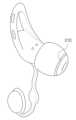
도 1은 일실시예에 따른 이어버드 전자 장치를 도시한다.
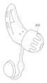
도 2는 도 1의 실시예에 따른 이어버드 전자 장치의 배면을 도시한다.
도 3은 일실시예에 따른 이어버드 전자 장치의 이어팁 전극을 설명하기 위한 도면이다.
도 4는 다른 일실시예에 따른 이어버드 전자 장치의 이어팁 전극을 설명하기 위한 도면이다.
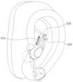
도 5는 일실시예 따른 이어윙 구조가 사용자의 귓바퀴 내측에 끼워지면서 이어윙 전극이 피부에 접촉되는 과정을 설명하기 위한 도면이다.
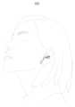
도 6은 일실시예에 다른 이어버드 전자 장치를 사용자가 착용한 모습을 도시한다.
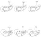
도 7은 다양한 실시예들에 따른 이어윙 구조들을 설명한다.
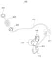
도 8은 다른 일실시예에 다른 이어버드 전자 장치를 도시한다.
도 9는 도 8의 실시예에 따른 이어버드 전자 장치를 사용자가 착용한 모습을 도시한다.
도 10은 또 다른 일실시예에 다른 이어버드 전자 장치를 도시한다.
도 11은 도 10의 실시예에 따른 이어버드 전자 장치를 사용자가 착용한 모습을 도시한다.
도 12는 일실시예에 따른 이어버드 전자 장치의 수납 및 충전 케이스를 도시한다.
도 13은 도 12의 구동의 예를 설명하기 위한 도면이다.1 shows an earbud electronic device according to one embodiment.
FIG. 2 shows a rear view of the earbud electronic device according to the embodiment of FIG. 1 .
FIG. 3 is a diagram for explaining an eartip electrode of an earbud electronic device according to an embodiment.
Figure 4 is a diagram for explaining an eartip electrode of an earbud electronic device according to another embodiment.
Figure 5 is a diagram for explaining a process in which the ear wing electrode is in contact with the skin while the ear wing structure according to one embodiment is fitted inside the user's ear.
Figure 6 shows a user wearing another earbud electronic device according to one embodiment.
Figure 7 explains ear wing structures according to various embodiments.
8 shows another earbud electronic device according to another embodiment.
Figure 9 shows a user wearing the earbud electronic device according to the embodiment of Figure 8.
Figure 10 shows another earbud electronic device according to another embodiment.
FIG. 11 shows a user wearing the earbud electronic device according to the embodiment of FIG. 10 .
Figure 12 shows a storage and charging case for an earbud electronic device according to an embodiment.
FIG. 13 is a diagram for explaining an example of driving in FIG. 12.
이하에서, 실시예들을 첨부된 도면을 참조하여 상세하게 설명한다. 그러나, 권리범위가 이러한 실시예들에 의해 제한되거나 한정되는 것은 아니다. 각 도면에 제시된 동일한 참조 부호는 동일한 부재를 나타낸다.Hereinafter, embodiments will be described in detail with reference to the attached drawings. However, the scope of rights is not limited or limited by these embodiments. The same reference numerals in each drawing indicate the same members.
아래 설명에서 사용되는 용어는, 연관되는 기술 분야에서 일반적이고 보편적인 것으로 선택되었으나, 기술의 발달 및/또는 변화, 관례, 기술자의 선호 등에 따라 다른 용어가 있을 수 있다. 따라서, 아래 설명에서 사용되는 용어는 기술적 사상을 한정하는 것으로 이해되어서는 안 되며, 실시예들을 설명하기 위한 예시적 용어로 이해되어야 한다.The terms used in the description below have been selected as general and universal in the related technical field, but there may be different terms depending on technological developments and/or changes, customs, technicians' preferences, etc. Accordingly, the terms used in the description below should not be understood as limiting the technical idea, but should be understood as illustrative terms for describing embodiments.
또한 특정한 경우는 출원인이 임의로 선정한 용어도 있으며, 이 경우 해당되는 설명 부분에서 상세한 그 의미를 기재할 것이다. 따라서 아래 설명에서 사용되는 용어는 단순한 용어의 명칭이 아닌 그 용어가 가지는 의미와 명세서 전반에 걸친 내용을 토대로 이해되어야 한다.In addition, in certain cases, there are terms arbitrarily selected by the applicant, and in this case, the detailed meaning will be described in the relevant description section. Therefore, the terms used in the description below should be understood based on the meaning of the term and the overall content of the specification, not just the name of the term.
도 1은 일실시예에 따른 이어버드 전자 장치(100)를 도시한다.Figure 1 shows an earbud
장치(100)는 사용자의 귀에 착용될 수 있는(wearable) 기기이다. 장치(100)는 사용자의 EEG 및 혈중산소포화도(SpO2) 등의 생체 정보를 측정한다. 사람의 EEG가 측정되면 수면 단계, 이를테면 REM수면, 수면 1단계, 2단계 등을 구분할 수 있다. 뇌파 신호를 처리하여 알파파, 베타파 등의 도미넌트 파형을 식별함으로써 어떤 레벨에서 잠이 드는지(입면 시 레벨), 잠을 자면서 수면 단계가 어떻게 변화하고 있고, 각 단계의 지속 시간은 얼마이며, 수면 파형의 변화가 몇 주기를 거치는지 등의 정보를 모니터링 할 수 있다.
나아가 SpO2를 측정함으로써 수면 중에 겪게 되는 수면 장애, 이를테면 수면무호흡을 감지하고, 나아가 이 때 적절한 피드백을 제공할 수 있다. 피드백은 이를 테면 사운드를 통해 사람의 귀에 경고를 한다던지, 수면 단계를 다른 단계로 변경 한다던지, 또는 잠에서 깬 후 연동되는 어플리케이션을 통해 수면 장애에 대한 정보를 주는 것이다.Furthermore, by measuring SpO2, sleep disorders experienced during sleep, such as sleep apnea, can be detected and appropriate feedback can be provided at this time. Feedback is, for example, warning the person's ears through sound, changing the sleep stage to another stage, or providing information about sleep disorders through an application that is linked after waking up.
종전에 알려진 뇌파 측정기들은 의료기기 레벨에서 적용되는 것이 대부분이었고, 사용자가 직접 사용하는 헬스케어 기기 레벨에서도 대부분 이마 전극을 따로 구비하여 착용에 불편함을 주었다. 본 명세서에서 제시한 선행기술문헌 등 일부 사례에서는 이마 전극을 제외하여 간편성을 높이고자 한 경우가 있으나, 아이디어 차원에서 그치고 실용적이지 못한 것은 (의료기기 레벨의 제품에 비해) 사용자가 수면 중에 착용하는 경우 전극이 사용자의 피부에서 떨어지는 등 측정의 연속성이 유지되지 못하는 것이 이유 중 하나이다. 또한 전극의 배치에 있어서, 기준전극 대 신호 전극(들)이 서로 간섭 없이 적절한 위치에 배치되지 못하는 문제도 있었다.Previously known EEG measuring devices were mostly applied at the medical device level, and even at the healthcare device level for direct use by users, most had separate forehead electrodes, making them inconvenient to wear. In some cases, such as the prior art literature presented in this specification, an attempt was made to increase convenience by excluding the forehead electrode, but it is only an idea and is not practical (compared to medical device level products) when the user wears it while sleeping. One of the reasons is that the continuity of measurement is not maintained, such as when the electrode falls off the user's skin. Additionally, in the arrangement of electrodes, there was a problem in which the reference electrode and the signal electrode(s) could not be placed in an appropriate position without interfering with each other.
일실시예에 따르면, 전자 장치(100)는 사용자의 귓볼(lobule or lobe)을 감싸 고정되면서 상기 귓볼에 매달려 상기 사용자의 혈중산소포화도(SpO2)를 측정하는 혈중산소포화도 측정부(110)를 포함하며 여기에 사용자 피부에 접촉하는 기준 전극을 배치한다. 이렇게 기준 전극이 전극이 배치될 외이도 내부 및/또는 귓바퀴 내측 피부와는 전기적 간섭이 덜하고 비교적 이격된 위치에 있어서, 전자 장치(100)의 EEG 측정은 종전에 알려진 제품들 대비 측정의 정확성, 재현성, 편의성 면에서 우수하다. 혈중산소포화도 측정부의 제1 파트(110)에는 LED 광원(111)과 수광부(들)(112)이 포함되며, 이러한 부분들과 구분되는 제2 파트(120)에는 예시적으로, 그러나 한정되지 않게 자석과 같은 고정수단이 포함된다. 귓볼을 중간에 두고 제1 파트(110)와 제2 파트(120)가 서로 마주보며 자력에 의해 붙어 혈중산소포화도 측정부, 및 EEG 측정을 위한 기준전극이 귓볼에 접촉하여 유지된다. 제1 파트(110)와 제2 파트(120) 사이 부분은 유연성 소재로 이루어진 브릿지일 수 있다.According to one embodiment, the
한편, 다른 실시예에 따르면, 상기 혈중산소포화도 측정부의 제1 파트(110)와 제2 파트(120) 사이의 브릿지 자체가 'U'형(U-shaped) 커브를 갖는 탄성 소재일 수 있다. 이 때 상기 제1 파트와 상기 제2 파트는 상기 귓볼을 사이에 두고 상기 탄성 브릿지의 탄력에 의해 상기 귓볼의 양쪽 면에서 서로 대향하면서 상기 귓볼에 매달릴 수 있다. 귓볼에 끼워 고정하는 형식이 된다.Meanwhile, according to another embodiment, the bridge itself between the
또 다른 일실시예에 따르면, 상기 연결 브리지가 힌지 구조로 되어 있어서 제1 파트(110)와 제2 파트(120)가 그러한 구조에 의해 폴딩-언폴딩 되면서 열렸다 닫히며 귓볼에 고정될 수도 있다. 그 외 다른 연결 브릿지 구조도 가능하며 일부 실시예로 국한되어 해석되지 않는다.According to another embodiment, the connection bridge has a hinge structure, so that the
장치(100)의 이어팁(ear tip)(130)은 사용자의 외이도(ear canal) 경부에 삽입되며, 상기 외이도 내 피부 상에 접하는 적어도 하나의 인이어(in-ear) 전극을 갖는다. 이어팁(130)은 통상의 인-이어 타입 이어버드 이어폰과 같이 사운드를 출력하는 파트가 되기도 한다. 외이도 경부에 삽입되며 사용자의 외이도 내벽에 밀착되기 때문에, 이어팁(130)은 사용자의 수면 중에도 전기적으로 지속적인 전기적 접촉(contact)을 유지하는 훌륭한 신호 전극이 된다. 이어팁(130)의 구조와 인이어 전극에 관해서는 도 3 내지 도 4를 참조하여 보다 상세히 후술한다.The
한편, 장치(100)은 이어팁(130)을 사용자의 외이도 내측으로 밀어 넣어 빠지지 않도록 지지하며, 사용자의 귓바퀴(antihelix) 내측에 끼워져 고정되는 이어윙(ear wing)(140)을 포함한다.Meanwhile, the
예시적으로, 그러나 한정되지 않게, 이어윙(140)의 윙 구조는 루프(loop) 형태이다. 일실시예에 따르면, 상기 윙 구조는 사용자의 다양한 귓바퀴 크기와 구조에 대응하기 위해 마련된 탄성구조(141)을 포함한다. 탄성구조(141)은 복수의 슬릿을 포함하여 다른 부분보다 상대적으로 높은 유연성 및/또는 신축성을 갖는다. 유연성 및/또는 신축성이 높다는 것은 외력 - 이를테면 응축력이나 뒤틀리는 힘 -에 의해 윙 구조 내의 다른 부분, 이를테면 이어윙 전극이 배치되는 부분(142)보다 더 많이 변형되었다가 외력이 약해지면 다시 복원되는 탄성을 갖는 것을 의미한다. 이어윙(140)의 윙 구조는 엘라스토머(elastomer), 고무(rubber), 실리콘 기타 폴리머(중합체) 등의 소재에서 선택되는 것일 수 있으며, 윙 구조에 부분적으로 포함되는 탄성구조(141)는 윙 다른 부분과 형태적으로 구별되도록 가공 또는 성형되어 있으나 소재에 있어서는 동일할 수 있다. 물론 소재에 차이가 있는 경우도 가능하다. 여기서 상기 탄성구조(141)는 외력에 의해 변형되어 상기 윙 구조가 상기 귓바퀴 내측으로 들어가도록 하고, 상기 외력이 상대적으로 약해지는 경우 상기 윙 구조를 복원하여 상기 윙 구조가 상기 귓바퀴 내측에 끼워져 지지되도록 하면서 상기 적어도 하나의 이어윙 전극이 상기 접하는 면에 밀착되도록 한다. 따라서 상기 이어윙 전극이 사용자의 귓바퀴 내측 피부에 밀착되는 것을 돕고, 따라서 EEG 신호의 측정을 위한 전기적인 접촉에 유리하다. 이러한 구조에 의해 EEG 측정을 위한 신호 전극들이 배치되는 부분(142)이 사용자의 수면 중에도 전기적 접촉을 유지하게 된다. 이어윙 전극이 배치되는 부분(142)에 대해서는 도 2을 참조하여 보다 상세히 후술한다.By way of example, but not limitation, the wing structure of the
이렇게 이어팁(130)과 이어윙(140)의 일부분(142)에 신호 전극들이 배치되고, 사용자의 귓볼에 접촉하는 혈중산소포화도 측정부(110)에 기준 전극이 배치되어, EEG 측정부(150)는 사용자의 뇌전도 신호를 수집한다. EEG 측정부(150)의 내부에는 PCB 또는 FPCB 상에 컨트롤 유닛, 플래시 메모리, 각종 증폭기 등의 회로가 포함되며, 이어팁(130)으로 소리를 출력하는 사운드 드라이버, 외부 디바이스(이를 테면 스마트폰)과 통신하는 통신 칩셋과 안테나가 배치될 수 있다.In this way, signal electrodes are placed on the
일실시예에 따르면 EEG 측정부(150) 내에 자이로 센서가 함께 포함되어 장치(100)를 착용한 사용자가 누워있는 상태인지 앉거나 서 있는 상태인지의 자세를 측정한다. 이렇게 측정한 자세가 EEG를 통해 측정되는 사용자의 수면 여부 및/또는 수면 레벨과 함께 고려되어, 사용자가 누워 있으나 잠을 들지(입면) 못하고 얼마나 오랜 시간을 있는지에 대해 확인할 수 있다. 도 2를 참조하여 더 설명한다.According to one embodiment, a gyro sensor is included in the
도 2는 도 1의 실시예에 따른 이어버드 전자 장치의 배면을 도시한다.FIG. 2 shows a rear view of the earbud electronic device according to the embodiment of FIG. 1 .
일실시예에 따르면, 상기 이어윙(140)의 부분(142)에서 사용자의 귓바퀴 내측에 접하는 측면에 적어도 하나의 이어윙 전극(들)(210, 220)을 포함한다. 이 전극(210, 220)도 EEG 측정부(150)이 EEG를 측정하는 신호 전극이 된다. 전극(210, 220)은 전도성 금속 소재일 수 있지만, 전도성 폴리머 기타 표면 산화막 형성이 최소화되는 알려진 다른 소재일 수도 있다. 탄성부(141)이 응축하였다가 다시 복원되는 과정에서 전극(210, 220)을 사용자의 귓바퀴 내측 벽면으로 더 강하게 밀어 접촉시키고 접촉력을 유지시키는 면에서, 사용자가 수면 상태에서 뒤척이더라도 전기적 접속을 유지하는 면에서 EEG 측정의 지속성을 보장할 뿐만 아니라, 귓바퀴 내측 벽면은 접촉 저항의 면에서 귀의 외이도 내벽과 마찬가지로 우수한 측정 부위가 되기 때문에 장치(100)의 구조는 생체 정보 측정에 매우 유리하게 설계되었다.According to one embodiment, the
충전단자(240)는 도 12 내지 도 13에서 도시되는 충전 및 수납 케이스 내에서 EEG 측정부(150)의 배터리를 충전시키는 전기 접속 단자가 된다.The charging
이어팁(130)의 커널(131)은 인-이어 타입 이어폰의 사운드 출력부와 같은 역할을 하며, 장치(100)가 수면 모니터링 및 사용자 가이드를 할 때 적절한 알람음, 음성 정보 기타 사운드를 출력할 수 있다. 이어팁(130) 자체가 전도성 고무, 기타 전도성 폴리머 소재로서 유연성이 있는 전도체일 수 있고 이 경우 이어팁(130)의 표면 층이 이어팁 전극일 수 있다. 그러나 이러한 특정한 하나의 실시예로 한정되지 않으며 다른 실시예들도 가능하며 도 3 내지 도 4를 참조하여 설명한다.The
도 3은 일실시예에 따른 이어버드 전자 장치의 이어팁 전극을 설명하기 위한 도면이다.FIG. 3 is a diagram for explaining an eartip electrode of an earbud electronic device according to an embodiment.
상술한 실시예와 같이 이어팁(130)의 표피 자체가 전도성 고무, 전도성 폴리머 등의 유연 전극일 수도 있으나, 도 3에서 도시된 실시예에서는 이어팁 전극(310)이 별도로 구비된다. 이 경우 이어팁 전극(310)을 제외한 이어팁(130)의 다른 부분은 절연성 실리콘, 절연성 고무, 절연성 폴리머 등의 절연성 소재일 수 있다. 이어팁 전극(310) 부분은 전도성 금속일 수도 있지만, 바람직하게는, 그러나 한정되지 않게, 이어팁 전극(310)이 전도성 고무, 전도성 폴리머 등 산화막 형성이 어려운 생체적합성을 갖는 전도성 소재일 수 있다. 도 3에서 도시된 예에서는 이어팁 전극(310)이 환(rim) 형태로 배치되나, 이에 한정되지 않고 스팟(spot) 타입의 돌출 전극이 되는 등 패턴에 있어서는 다양한 변형이 가능하다. 다만, 외이도 내측 피부 벽면에 밀착되어 전기적 접촉을 이루어야 하므로 커널(131) 쪽에 치우치지 않고 이어팁(130)이 외이도 벽면과 접촉하는 옆면에 배치되는 것이 바람직하다.As in the above-described embodiment, the skin of the
도 4는 다른 일실시예에 따른 이어버드 전자 장치의 이어팁 전극을 설명하기 위한 도면이다.Figure 4 is a diagram for explaining an eartip electrode of an earbud electronic device according to another embodiment.
도시된 바와 같이 전기적 접촉을 더 넓고 안정적으로 만들기 위해 다른 패턴의 이어팁 전극(410)이 디자인될 수도 있다. 상술한 바와 같이 사용자의 외이도 내측 피부에 밀착되어 전기적 접촉을 유지하고, 사용자가 수면 중 뒤척이거나 베개나 사용자의 손이 닿아서 움직이더라도 전기적 접촉은 유지되도록 고안될 수 있다.As shown,
도 5는 일실시예 따른 이어윙 구조가 사용자의 귓바퀴 내측에 끼워지면서 이어윙 전극이 피부에 접촉되는 과정을 설명하기 위한 도면이다.Figure 5 is a diagram for explaining a process in which the ear wing electrode is in contact with the skin while the ear wing structure according to one embodiment is fitted inside the user's ear.
이어윙의 윙구조에 포함되는 탄성구조(510)은 상술한 바와 같이 복수의 슬릿을 포함하여 다른 부분보다 상대적으로 높은 유연성 및/또는 신축성을 갖는다. 이러한 탄성구조(510)은 사용자의 귓바퀴 내측의 공간의 크기와 모양이 다양한 경우 적응적으로 맞추어질 수 있는 것을 기대하여 구비되지만, 본발명의 실시예들에 있어서 그에 못지 않은 중요한 기능은 이어윙 전극들(도 2의 210, 220)이 사용자의 귓바퀴 내측 벽면의 방향으로(각 전극들이 각각 520, 530 방향으로) 밀착되어 전기적 접촉을 유지하도록 하는 것이다. 탄성구조(510)의 탄성 복원력이 전극(210, 220)의 전기적 접촉을 제공하고 유지함으로써 EEG 신호의 측정을 위한 전기적인 접촉의 안정성과 지속성이 유지되며, 이는 EEG 측정을 위한 전기적 신호 측정에 있어서 저항을 용인 가능한 수준으로 유지하고 전기적/열적 노이즈를 줄이는 역할을 한다. 따라서 사용자가 수면 중 뒤척이거나, 귀 부분이 베개(pillow)에 눌려 있는 경우라도 전극들(210, 220)이 귀 내측 피부와 전기적 접촉을 유지한다.As described above, the
도 6은 일실시예에 다른 이어버드 전자 장치를 사용자가 착용한 모습(600)을 도시한다.Figure 6 shows a user wearing another earbud electronic device (600) according to one embodiment.
전자 장치는 왼쪽 귀에 착용하는 타입과, 우측 귀에 착용하는 타입으로 구비될 수 있으며, 일반적으로 이 중 하나를 사용자가 선택하여 구매 및 착용할 수 있다. 도시된 바와 같이 혈중산소포화도 측정부는 사용자의 귓볼에 밀착하여 고정되고, 이어팁은 사용자의 외이도 경부에 삽입되며 이어윙은 귓바퀴 내측에 끼워져 고정된다. 이러한 구조에 의해 이어팁 전극(들)과 이어윙 전극(들)은 신호 전극으로서 안정적인 전기적 접촉을 수면 내내 유지한다. 기준 전극이 귓볼 부분의 혈중산소포화도 측정기의 파트에 있기 때문에, 전기적으로 안정된 신호 측정이 가능하다.Electronic devices can be of a type worn on the left ear and a type worn on the right ear, and a user can generally select one of these to purchase and wear. As shown, the blood oxygen saturation measuring unit is fixed in close contact with the user's earlobe, the ear tip is inserted into the neck of the user's external auditory canal, and the ear wing is fitted and fixed inside the ear canal. Due to this structure, the ear tip electrode(s) and ear wing electrode(s) maintain stable electrical contact as signal electrodes throughout sleep. Because the reference electrode is located on the earlobe part of the blood oxygen saturation meter, electrically stable signal measurement is possible.
도 7은 다양한 실시예들에 따른 이어윙 구조들을 설명한다.Figure 7 explains ear wing structures according to various embodiments.
도 1을 참조하여 설명한 구조의 정면도와 사시도가 각각 구조(710, 711)이다. 예시적으로, 그러나 한정되지 않게, 이어윙의 윙구조는 엘라스토머(elastomer), 고무(rubber), 실리콘 기타 폴리머 등의 유연성 소재에서 선택되는 것일 수 있으며, 탄성구조(710, 711)는 윙 다른 부분과 형태적으로 구별되도록 가공 또는 성형되어 있으나 소재에 있어서는 동일할 수 있다. 물론 소재에 차이가 있는 경우도 가능하다. 탄성구조(710, 711)에서는 일측면만 여러 개의 홈이 파져서 누르거나 비트는 외력에 의해 다른 부분보다 탄성구조(710, 711) 부분이 더 많이 눌리거나 뒤틀리게 된다.The front view and perspective view of the structure described with reference to FIG. 1 are
이러한 탄성구조는 다양한 변형도 가능한데, 그 기능적 목적이 동일하다면 지그재그 타입으로 꺾여 성형된 탄성구조(720, 721)의 형태도 가능하다. 신발 밑창에서 충격 흡수를 위해 구비되는 탄성부의 모양과 유사하다. 또한 다른 실시예에서는 윙 구조의 다른 부분에 대해 소재적으로 더 유연하고 잘 변형되는 소재가 선택된 탄성구조(730, 731)도 가능하다. 이 경우 소재의 이중성이라는 공정상 불리함이 있지만, 외적으로는 이러한 구조에 선호가 있을 수 있다. 또한, 소재가 동일하더라도 굵기(외주 둘레)이 미차를 두어 다른 부분보다 해당 탄성구조(730, 731) 부분이 더 잘 변형되었다가 복원되도록 설계하는 것도 가능하다.This elastic structure can be modified in various ways. As long as the functional purpose is the same, the
도 8은 다른 일실시예에 다른 이어버드 전자 장치(800)를 도시한다.Figure 8 shows another earbud
도 1 등을 참조하여 설명된 실시예와의 차이는 확장 전극(820. 830) 및 그 확장 전극과의 전기적 연결을 위한 연결선(810)의 존재이다. 연결선(810)은 혈중산소포화도 측정부의 제1 파트(110)의 연결부(812)를 통해 EEG 측정부와 연결된다. 이 연결부(812)는 전기적 접속을 제공하는 커넥터로서 그 형태와 체결 구조에 있어서는 다양한 방법이 가능하다. 이러한 확장 전극(820, 830)은 각각 사용자의 관자놀이와 이마에 부착되는 전극들일 수 있다. 전극(820)은 관자놀이에 패치전극 형태로 부착되고, 전극(830)은 이마에 패치전극 형태로 부착된다.The difference from the embodiment described with reference to FIG. 1 and the like is the presence of the
한편, 연결선(810)에는 사람의 머리 크기와 형태에 적응적으로 대응하기 위해 접힘 구조(811, 821)이 구비될 수 있다. 이러한 접힘 구조에 의해, 머리가 큰 사람부터 작은 사람까지 접힘 구조가 부분적으로 펴지면서 대응이 가능하여, 착용하는 사람에게 편안함을 제공하고, 확장 전극들(820, 830)이 수면 중에 당겨져서 떨어지지 않고 잘 붙어있게 되는 기능을 제공한다. 도 9는 도 8의 실시예에 따른 이어버드 확장 전극을 갖는 전자 장치를 사용자가 착용한 모습(900)을 도시한다.Meanwhile, the
도 10은 또 다른 일실시예에 다른 이어버드 전자 장치를 도시한다.Figure 10 shows another earbud electronic device according to another embodiment.
이러한 실시예의 타입을 프로형(pro-type)이라고 명명하는 것이 가능하다. 이는 확장 전극 및 연결선을 구비한 도 8 내지 도 9의 장치가 왼쪽 세트(left set)와 오른쪽 세트(right set)의 한 조로 구비되며, 양쪽 세트 사이는 연결 밴드(1060 및 1061)이 물리적으로 결합하여 착용 시의 안정성에 기여한다.It is possible to name this type of embodiment as pro-type. This means that the devices of FIGS. 8 and 9 equipped with expansion electrodes and connection lines are provided as a left set and a right set, and
왼쪽 세트에는 도 8을 참조하여 앞서 설명한 전자 장치(1010), 확장 전극(1030, 1040), 연결선(1020) 및 접힘 구조(1040) 등이 구비된다. 그리고, 이와 대칭적으로 오른쪽 세트에도 별도의 장치(1011), 확장 전극(1031, 1051), 연결선(1021) 및 접힘 구조(1041)이 구비된다. 이러한 프로형은 더욱 높은 정밀도와 재현도, 및 오차 보정이 가능한 EEG 측정, SpO2 측정을 가능하게 하며, 수면 상태, 수면 자세 등 모든 측정에 있어서 듀얼리티(duality)를 제공함으로써 측정 결과의 신뢰도를 높일 수 있다. 도 11은 도 10의 실시예에 따른 이어버드 전자 장치를 사용자가 착용한 모습(1100)을 도시한다.The left set includes the
도 12는 일실시예에 따른 이어버드 전자 장치의 수납 및 충전 케이스에 수납된 모습(1200)을 도시한다. 예시적으로 도 8을 참조하여 설명한 전자 장치(800)이 케이스(1210)에 수납되어 있다. 수납된 상태에서 도 2에서 설명한 충전 단자(240)가 케이스(1210) 측의 충전 단자와 전기적으로 접속되며, 여기에는 자석에 의한 자기적 인력으로 체결력이 안정적으로 유지되는 것도 가능하다. 겉 커버(1220)은 미적인 고려를 위해, 또한 내부의 LED 램프의 상태를 확인하기 위해 투명 또는 반투명 재질로 이루어질 수 있다. 이 케이스의 구조는 도 13을 통해 좀 더 설명한다.FIG. 12 shows an earbud electronic device stored in a storage and charging case (1200) according to an embodiment. By way of example, the
도 13은 도 12의 구동의 예를 설명하기 위한 모습(1300)이다. 커버(1220)는 열렸다 닫힐 수 있는 구조이고, 케이스(1210) 내에서 슬라이딩 구조로 내부 구조(1310)가 상하 방향(1311)로 전개되거나 회수될 수 있다. 확장 전극을 위한 연결선은 내부 구조(1310)의 외주면에 감겨 수납될 수 있다.FIG. 13 is a view 1300 for explaining an example of driving in FIG. 12. The cover 1220 has a structure that can be opened and closed, and the internal structure 1310 can be deployed or recovered in the vertical direction 1311 by sliding within the case 1210. The connection wire for the expansion electrode may be wrapped and stored around the outer circumferential surface of the internal structure 1310.
이상에서 설명된 장치는 하드웨어 구성요소, 소프트웨어 구성요소, 및/또는 하드웨어 구성요소 및 소프트웨어 구성요소의 조합으로 구현될 수 있다. 예를 들어, 실시예들에서 설명된 장치 및 구성요소는, 예를 들어, 프로세서, 콘트롤러, ALU(arithmetic logic unit), 디지털 신호 프로세서(digital signal processor), 마이크로컴퓨터, FPA(field programmable array), PLU(programmable logic unit), 마이크로프로세서, 또는 명령(instruction)을 실행하고 응답할 수 있는 다른 어떠한 장치와 같이, 하나 이상의 범용 컴퓨터 또는 특수 목적 컴퓨터를 이용하여 구현될 수 있다. 처리 장치는 운영 체제(OS) 및 상기 운영 체제 상에서 수행되는 하나 이상의 소프트웨어 애플리케이션을 수행할 수 있다. 또한, 처리 장치는 소프트웨어의 실행에 응답하여, 데이터를 접근, 저장, 조작, 처리 및 생성할 수도 있다. 이해의 편의를 위하여, 처리 장치는 하나가 사용되는 것으로 설명된 경우도 있지만, 해당 기술분야에서 통상의 지식을 가진 자는, 처리 장치가 복수 개의 처리 요소(processing element) 및/또는 복수 유형의 처리 요소를 포함할 수 있음을 알 수 있다. 예를 들어, 처리 장치는 복수 개의 프로세서 또는 하나의 프로세서 및 하나의 컨트롤러를 포함할 수 있다. 또한, 병렬 프로세서(parallel processor)와 같은, 다른 처리 구성(processing configuration)도 가능하다.The device described above may be implemented with hardware components, software components, and/or a combination of hardware components and software components. For example, devices and components described in embodiments may include, for example, a processor, a controller, an arithmetic logic unit (ALU), a digital signal processor, a microcomputer, a field programmable array (FPA), It may be implemented using one or more general-purpose or special-purpose computers, such as a programmable logic unit (PLU), microprocessor, or any other device capable of executing and responding to instructions. A processing device may execute an operating system (OS) and one or more software applications that run on the operating system. Additionally, a processing device may access, store, manipulate, process, and generate data in response to the execution of software. For ease of understanding, a single processing device may be described as being used; however, those skilled in the art will understand that a processing device includes multiple processing elements and/or multiple types of processing elements. It can be seen that it may include. For example, a processing device may include multiple processors or one processor and one controller. Additionally, other processing configurations, such as parallel processors, are possible.
소프트웨어는 컴퓨터 프로그램(computer program), 코드(code), 명령(instruction), 또는 이들 중 하나 이상의 조합을 포함할 수 있으며, 원하는 대로 동작하도록 처리 장치를 구성하거나 독립적으로 또는 결합적으로(collectively) 처리 장치를 명령할 수 있다. 소프트웨어 및/또는 데이터는, 처리 장치에 의하여 해석되거나 처리 장치에 명령 또는 데이터를 제공하기 위하여, 어떤 유형의 기계, 구성요소(component), 물리적 장치, 가상 장치(virtual equipment), 컴퓨터 저장 매체 또는 장치, 또는 전송되는 신호 파(signal wave)에 영구적으로, 또는 일시적으로 구체화(embody)될 수 있다. 소프트웨어는 네트워크로 연결된 컴퓨터 시스템 상에 분산되어서, 분산된 방법으로 저장되거나 실행될 수도 있다. 소프트웨어 및 데이터는 하나 이상의 컴퓨터 판독 가능 기록 매체에 저장될 수 있다.Software may include a computer program, code, instructions, or a combination of one or more of these, which may configure a processing unit to operate as desired, or may be processed independently or collectively. You can command the device. Software and/or data may be used on any type of machine, component, physical device, virtual equipment, computer storage medium or device to be interpreted by or to provide instructions or data to a processing device. , or may be permanently or temporarily embodied in a transmitted signal wave. Software may be distributed over networked computer systems and stored or executed in a distributed manner. Software and data may be stored on one or more computer-readable recording media.
실시예에 따른 방법은 다양한 컴퓨터 수단을 통하여 수행될 수 있는 프로그램 명령 형태로 구현되어 컴퓨터 판독 가능 매체에 기록될 수 있다. 상기 컴퓨터 판독 가능 매체는 프로그램 명령, 데이터 파일, 데이터 구조 등을 단독으로 또는 조합하여 포함할 수 있다. 상기 매체에 기록되는 프로그램 명령은 실시예를 위하여 특별히 설계되고 구성된 것들이거나 컴퓨터 소프트웨어 당업자에게 공지되어 사용 가능한 것일 수도 있다. 컴퓨터 판독 가능 기록 매체의 예에는 하드 디스크, 플로피 디스크 및 자기 테이프와 같은 자기 매체(magnetic media), CD-ROM, DVD와 같은 광기록 매체(optical media), 플롭티컬 디스크(floptical disk)와 같은 자기-광 매체(magneto-optical media), 및 롬(ROM), 램(RAM), 플래시 메모리 등과 같은 프로그램 명령을 저장하고 수행하도록 특별히 구성된 하드웨어 장치가 포함된다. 프로그램 명령의 예에는 컴파일러에 의해 만들어지는 것과 같은 기계어 코드뿐만 아니라 인터프리터 등을 사용해서 컴퓨터에 의해서 실행될 수 있는 고급 언어 코드를 포함한다. 상기된 하드웨어 장치는 실시예의 동작을 수행하기 위해 하나 이상의 소프트웨어 모듈로서 작동하도록 구성될 수 있으며, 그 역도 마찬가지이다.The method according to the embodiment may be implemented in the form of program instructions that can be executed through various computer means and recorded on a computer-readable medium. The computer-readable medium may include program instructions, data files, data structures, etc., singly or in combination. Program instructions recorded on the medium may be specially designed and configured for the embodiment or may be known and available to those skilled in the art of computer software. Examples of computer-readable recording media include magnetic media such as hard disks, floppy disks, and magnetic tapes, optical media such as CD-ROMs and DVDs, and magnetic media such as floptical disks. -Includes optical media (magneto-optical media) and hardware devices specifically configured to store and execute program instructions, such as ROM, RAM, flash memory, etc. Examples of program instructions include machine language code, such as that produced by a compiler, as well as high-level language code that can be executed by a computer using an interpreter, etc. The hardware devices described above may be configured to operate as one or more software modules to perform the operations of the embodiments, and vice versa.
실시예들이 비록 한정된 도면에 의해 설명되었으나, 해당 기술분야에서 통상의 지식을 가진 자라면 상기의 기재로부터 다양한 수정 및 변형이 가능하다. 예를 들어, 설명된 기술들이 설명된 방법과 다른 순서로 수행되거나, 및/또는 설명된 시스템, 구조, 장치, 회로 등의 구성요소들이 설명된 방법과 다른 형태로 결합 또는 조합되거나, 다른 구성요소 또는 균등물에 의하여 대치되거나 치환되더라도 적절한 결과가 달성될 수 있다.Although the embodiments have been described with limited drawings, various modifications and variations can be made from the above description by those skilled in the art. For example, the described techniques are performed in a different order than the described method, and/or components of the described system, structure, device, circuit, etc. are combined or combined in a different form than the described method, or other components are used. Alternatively, appropriate results may be achieved even if substituted or substituted by an equivalent.
그러므로, 다른 구현들, 다른 실시예들 및 특허청구범위와 균등한 것들도 후술하는 특허청구범위의 범위에 속한다.Therefore, other implementations, other embodiments, and equivalents of the claims also fall within the scope of the claims described below.
100: 이어버드 전자 장치
110: 혈중산소포화도 측정부의 제1 파트
120: 혈중산소포화도 측정부의 제2 파트
130: 이어팁
140: 이어윙
150: EEG 측정부100: Earbud electronic device
110: First part of blood oxygen saturation measurement unit
120: Second part of blood oxygen saturation measurement unit
130: Ear tips
140: ear wing
150: EEG measurement unit
Claims (12)
Translated fromKorean상기 사용자의 외이도 경부에 삽입되어 상기 외이도 내 피부 상에 접하는 적어도 하나의 인이어 전극을 갖는 이어팁;
상기 이어팁을 상기 외이도 내측으로 밀어 지지하며, 상기 사용자의 귓바퀴 내측에 끼워져 고정되는 윙 구조의 탄성구조를 갖는 이어윙; 및
상기 적어도 하나의 인이어 전극과 상기 적어도 하나의 기준 전극 사이의 전위차에 기초하여 상기 사용자의 뇌전도(EEG)를 측정하는 EEG 측정부
를 포함하는 이어버드 전자 장치.A blood oxygen saturation measuring unit that is fixed around the user's earlobe and hangs on the earlobe to measure the user's blood oxygen saturation (SpO2) - the blood oxygen saturation measuring unit includes at least one reference electrode in contact with the user's earlobe. -;
An eartip having at least one in-ear electrode that is inserted into the neck of the user's external auditory canal and comes into contact with the skin within the external auditory canal;
An ear wing that supports the ear tip by pushing it inside the external auditory canal and has an elastic structure of a wing structure that is inserted and fixed inside the user's ear canal; and
An EEG measurement unit that measures the electroencephalogram (EEG) of the user based on the potential difference between the at least one in-ear electrode and the at least one reference electrode.
An earbud electronic device comprising a.
상기 이어윙은 상기 윙 구조가 상기 사용자의 상기 귓바퀴 내측에 접하는 면에 적어도 하나의 이어윙 전극을 더 포함하고,
상기 EEG 측정부는 상기 적어도 하나의 이어윙 전극 및 상기 적어도 하나의 기준 전극 사이의 전위차에 기초하여 상기 뇌전도를 측정하는 이어버드 전자 장치.According to paragraph 1,
The ear wing further includes at least one ear wing electrode on a surface of the wing structure in contact with the inside of the user's ear flap,
The EEG measuring unit is an earbud electronic device that measures the electroencephalogram based on a potential difference between the at least one ear wing electrode and the at least one reference electrode.
상기 윙 구조는 루프 형태이고, 상기 윙 구조는 복수의 슬릿을 포함하여 다른 부분보다 상대적으로 높은 유연성 및/또는 신축성을 갖는 탄성구조를 포함하고,
상기 탄성구조는 외력에 의해 변형되어 상기 윙 구조가 상기 귓바퀴 내측으로 들어가도록 하고, 상기 외력이 상대적으로 약해지는 경우 상기 윙 구조를 복원하여 상기 윙 구조가 상기 귓바퀴 내측에 끼워져 지지되도록 하면서 상기 적어도 하나의 이어윙 전극이 상기 접하는 면에 밀착되도록 하는 이어버드 전자 장치.According to paragraph 2,
The wing structure is in the form of a loop, and the wing structure includes an elastic structure that includes a plurality of slits and has relatively higher flexibility and/or elasticity than other parts,
The elastic structure is deformed by an external force so that the wing structure enters the inside of the auricle, and when the external force is relatively weak, the wing structure is restored so that the wing structure is fit and supported inside the auricle, and the at least one An earbud electronic device that allows the ear wing electrode to be in close contact with the contact surface.
상기 혈중산소포화도 측정부는, 혈중산소포화도를 측정하는 센서를 포함하는 제1 파트, 자석을 포함하는 제2 파트, 상기 제1 파트와 상기 제2 파트를 연결하는 유연성 브릿지를 포함하고,
상기 제1 파트와 상기 제2 파트는 상기 귓볼을 사이에 두고 상기 자석에 의한 자기적 인력에 의해 상기 귓볼의 양쪽 면에서 서로 대향하면서 상기 귓볼에 매달리는 이어버드 전자 장치.According to paragraph 1,
The blood oxygen saturation measurement unit includes a first part including a sensor for measuring blood oxygen saturation, a second part including a magnet, and a flexible bridge connecting the first part and the second part,
An earbud electronic device in which the first part and the second part are suspended from the earlobe while opposing each other on both sides of the earlobe by magnetic attraction caused by the magnet with the earlobe interposed therebetween.
상기 적어도 하나의 기준 전극은 상기 제1 파트 및 상기 제2 파트 중 적어도 하나에서 상기 귓볼에 접하도록 배치되는 것인 이어버드 전자 장치.According to paragraph 1,
The at least one reference electrode is disposed in contact with the earlobe in at least one of the first part and the second part.
상기 혈중산소포화도 측정부는, 혈중산소포화도를 측정하는 센서를 포함하는 제1 파트, 상기 기준 전극을 포함하는 제2 파트, 상기 제1 파트와 상기 제2 파트를 연결하는 'U'형 커브를 갖는 탄성 브릿지를 포함하고,
상기 제1 파트와 상기 제2 파트는 상기 귓볼을 사이에 두고 상기 탄성 브릿지의 탄력에 의해 상기 귓볼의 양쪽 면에서 서로 대향하면서 상기 귓볼에 매달리는 이어버드 전자 장치.According to paragraph 1,
The blood oxygen saturation measuring unit has a first part including a sensor for measuring blood oxygen saturation, a second part including the reference electrode, and a 'U'-shaped curve connecting the first part and the second part. Comprising an elastic bridge,
An earbud electronic device in which the first part and the second part face each other on both sides of the earlobe and hang on the earlobe by the elasticity of the elastic bridge with the earlobe in between.
상기 적어도 하나의 인이어 전극은 절연성 물질로 구성되는 상기 이어팁의 표면 상에 인쇄된 전도성 소재의 전극을 포함하는 이어버드 전자 장치.According to paragraph 1,
An earbud electronic device wherein the at least one in-ear electrode includes an electrode of a conductive material printed on a surface of the eartip made of an insulating material.
상기 이어팁은 상기 EEG 측정부와 전기적 연결되는 전도성 폴리머 소재로 구성되고, 상기 적어도 하나의 인이어 전극은 상기 이어팁의 표면인 이어버드 전자 장치.According to paragraph 1,
An earbud electronic device wherein the eartip is made of a conductive polymer material electrically connected to the EEG measurement unit, and the at least one in-ear electrode is a surface of the eartip.
상기 혈중산소포화도 측정부는 일측으로 상기 EEG 측정부와 전기적으로 접속하고, 타측에는 상기 사용자의 머리에 부착되는 별도의 확장 전극과 접속되는 연결부를 갖는 이어버드 전자 장치.According to paragraph 1,
The blood oxygen saturation measurement unit is electrically connected to the EEG measurement unit on one side, and the earbud electronic device has a connection portion connected to a separate expansion electrode attached to the user's head on the other side.
상기 이어팁을 상기 외이도 내측으로 밀어 지지하며, 상기 사용자의 귓바퀴 내측에 끼워져 고정되는 윙 구조의 탄성구조를 갖는 이어윙;
상기 사용자의 귓볼을 감싸 고정되면서 상기 귓볼에 매달려 상기 사용자의 혈중산소포화도(SpO2)를 측정하는 혈중산소포화도 측정부 - 상기 혈중산소포화도 측정부는 상기 사용자의 귓볼에 접촉하는 적어도 하나의 기준 전극을 포함함 -;
상기 혈중산소포화도 측정부에 연결되어 상기 사용자의 이마에 접하는 적어도 하나의 이마 전극; 및
상기 적어도 하나의 인이어 전극 및 상기 적어도 하나의 이마 전극들 각각과 상기 적어도 하나의 기준 전극 사이의 전위차에 기초하여 상기 사용자의 뇌전도(EEG)를 측정하는 EEG 측정부
를 포함하는 이어버드 전자 장치.An eartip having at least one in-ear electrode that is inserted into the neck of the user's external auditory canal and contacts the skin within the external auditory canal;
An ear wing that supports the ear tip by pushing it inside the external auditory canal and has an elastic structure of a wing structure that is inserted and fixed inside the user's ear canal;
A blood oxygen saturation measuring unit that is fixed around the user's earlobe and hangs on the earlobe to measure the user's blood oxygen saturation (SpO2) - the blood oxygen saturation measuring unit includes at least one reference electrode in contact with the user's earlobe Ham -;
at least one forehead electrode connected to the blood oxygen saturation measurement unit and in contact with the user's forehead; and
An EEG measurement unit that measures the user's electroencephalogram (EEG) based on a potential difference between each of the at least one in-ear electrode and the at least one forehead electrode and the at least one reference electrode.
An earbud electronic device comprising a.
상기 이어윙은 상기 윙 구조가 상기 사용자의 상기 귓바퀴 내측에 접하는 면에 적어도 하나의 이어윙 전극을 더 포함하고,
상기 EEG 측정부는 상기 뇌전도를 측정에 있어서 상기 적어도 하나의 이어윙 전극 및 상기 적어도 하나의 기준 전극 사이의 전위차를 더 이용하는 이어버드 전자 장치.According to clause 10,
The ear wing further includes at least one ear wing electrode on a surface of the wing structure in contact with the inside of the user's ear flap,
The EEG measuring unit further uses a potential difference between the at least one ear wing electrode and the at least one reference electrode when measuring the electroencephalogram.
상기 윙 구조는 루프 형태이고, 상기 윙 구조는 복수의 슬릿을 포함하여 다른 부분보다 상대적으로 높은 유연성 및/또는 신축성을 갖는 탄성구조를 포함하고,
상기 탄성구조는 외력에 의해 변형되어 상기 윙 구조가 상기 귓바퀴 내측으로 들어가도록 하고, 상기 외력이 상대적으로 약해지는 경우 상기 윙 구조를 복원하여 상기 윙 구조가 상기 귓바퀴 내측에 끼워져 지지되도록 하면서 상기 적어도 하나의 이어윙 전극이 상기 접하는 면에 밀착되도록 하는 이어버드 전자 장치.According to clause 11,
The wing structure is in the form of a loop, and the wing structure includes an elastic structure that includes a plurality of slits and has relatively higher flexibility and/or elasticity than other parts,
The elastic structure is deformed by an external force so that the wing structure enters the inside of the auricle, and when the external force is relatively weak, the wing structure is restored so that the wing structure is fit and supported inside the auricle, and the at least one An earbud electronic device that allows the ear wing electrode to be in close contact with the contact surface.
Priority Applications (6)
| Application Number | Priority Date | Filing Date | Title |
|---|---|---|---|
| KR1020220063458AKR20230163759A (en) | 2022-05-24 | 2022-05-24 | Biometric information measuring device |
| PCT/IB2022/062053WO2023084503A1 (en) | 2021-11-12 | 2022-12-12 | Device for monitoring sleep, and operation method therefor |
| PCT/IB2022/062049WO2023084502A1 (en) | 2021-11-12 | 2022-12-12 | Sleep monitoring device and operation method therefor |
| PCT/KR2022/020122WO2023229128A1 (en) | 2022-05-24 | 2022-12-12 | Biometric information measurement device |
| US18/709,753US20250000450A1 (en) | 2021-11-12 | 2022-12-12 | Sleep monitoring device and operation method therefor |
| EP22892267.0AEP4431007A4 (en) | 2021-11-12 | 2022-12-12 | SLEEP MONITORING DEVICE AND OPERATING METHOD THEREFOR |
Applications Claiming Priority (1)
| Application Number | Priority Date | Filing Date | Title |
|---|---|---|---|
| KR1020220063458AKR20230163759A (en) | 2022-05-24 | 2022-05-24 | Biometric information measuring device |
Publications (1)
| Publication Number | Publication Date |
|---|---|
| KR20230163759Atrue KR20230163759A (en) | 2023-12-01 |
Family
ID=88919407
Family Applications (1)
| Application Number | Title | Priority Date | Filing Date |
|---|---|---|---|
| KR1020220063458APendingKR20230163759A (en) | 2021-11-12 | 2022-05-24 | Biometric information measuring device |
Country Status (2)
| Country | Link |
|---|---|
| KR (1) | KR20230163759A (en) |
| WO (1) | WO2023229128A1 (en) |
Citations (3)
| Publication number | Priority date | Publication date | Assignee | Title |
|---|---|---|---|---|
| KR20160024903A (en) | 2016-02-19 | 2016-03-07 | 고려대학교 산학협력단 | method of manufaturing cap for detecting elctroencephalogram and Apparatus for detecting Electroencephalogram having shape of earphone with the cap |
| KR102046515B1 (en) | 2017-03-06 | 2019-11-20 | 주식회사 아이메디신 | Neckband type healthcare service method and system |
| KR102102421B1 (en) | 2018-01-09 | 2020-04-20 | 광운대학교 산학협력단 | EEG measuring earphone detecting sleepiness while driving and the system using it |
Family Cites Families (5)
| Publication number | Priority date | Publication date | Assignee | Title |
|---|---|---|---|---|
| DE102006023824B4 (en)* | 2006-05-20 | 2010-01-28 | Cerbomed Gmbh | Device for the transcutaneous application of a stimulus or for transcutaneous detection of a parameter |
| US9814426B2 (en)* | 2012-06-14 | 2017-11-14 | Medibotics Llc | Mobile wearable electromagnetic brain activity monitor |
| US9782584B2 (en)* | 2014-06-13 | 2017-10-10 | Nervana, LLC | Transcutaneous electrostimulator and methods for electric stimulation |
| CA3080600C (en)* | 2015-01-06 | 2022-11-29 | David Burton | Mobile wearable monitoring systems |
| US11110274B2 (en)* | 2016-03-15 | 2021-09-07 | Leonhardt Ventures Llc | System and method for treating inflammation |
- 2022
- 2022-05-24KRKR1020220063458Apatent/KR20230163759A/enactivePending
- 2022-12-12WOPCT/KR2022/020122patent/WO2023229128A1/ennot_activeCeased
Patent Citations (3)
| Publication number | Priority date | Publication date | Assignee | Title |
|---|---|---|---|---|
| KR20160024903A (en) | 2016-02-19 | 2016-03-07 | 고려대학교 산학협력단 | method of manufaturing cap for detecting elctroencephalogram and Apparatus for detecting Electroencephalogram having shape of earphone with the cap |
| KR102046515B1 (en) | 2017-03-06 | 2019-11-20 | 주식회사 아이메디신 | Neckband type healthcare service method and system |
| KR102102421B1 (en) | 2018-01-09 | 2020-04-20 | 광운대학교 산학협력단 | EEG measuring earphone detecting sleepiness while driving and the system using it |
Also Published As
| Publication number | Publication date |
|---|---|
| WO2023229128A1 (en) | 2023-11-30 |
Similar Documents
| Publication | Publication Date | Title |
|---|---|---|
| JP5695653B2 (en) | User skull electrode positioning device | |
| US20070238945A1 (en) | Electrode Headset | |
| KR102361026B1 (en) | Bioelectrical signal measuring apparatus | |
| US8565852B2 (en) | Auricle-installed device and bio-signal measurement apparatus | |
| US9788745B2 (en) | Biological signal measuring equipment | |
| US8692677B2 (en) | Wake-up assisting apparatus and wake-up assisting method | |
| US10881351B2 (en) | Multi-section finger sleeve-type probe | |
| JP6104035B2 (en) | Earphone and eye movement estimation device | |
| CN205697764U (en) | Glasses-type brain activity sensor and glasses-type electrophysiological activity sensing device | |
| KR101238192B1 (en) | Ear attachable sensor-set and operating method of the same | |
| JP6963250B2 (en) | Biological signal detection device and EEG measurement method | |
| CN116058792A (en) | Method for checking human body functions | |
| KR20230163759A (en) | Biometric information measuring device | |
| WO2024164906A1 (en) | A ear-wearable monitoring device for long term wearing | |
| CN113456085A (en) | Head-wearing type sleeping instrument | |
| EP4146056A1 (en) | Multi-body earpiece | |
| US20250000450A1 (en) | Sleep monitoring device and operation method therefor | |
| CN209003960U (en) | Multipurpose Physiological Detection System | |
| JP3156160B2 (en) | Physiological condition detection sensor device | |
| KR20230069811A (en) | Sleeping monitoring device and operating method thereof | |
| KR20250119564A (en) | Sleep care device and control method thereof | |
| KR20210000884A (en) | Biological signal measurement apparatus and system | |
| TWM566551U (en) | Multi-purpose physiological inspection device and system | |
| TW202502274A (en) | Electroencephalogram measuring device and gasket for electroencephalogram measuring device | |
| KR20250014399A (en) | Biosignal information measuring device |
Legal Events
| Date | Code | Title | Description |
|---|---|---|---|
| PA0109 | Patent application | Patent event code:PA01091R01D Comment text:Patent Application Patent event date:20220524 | |
| PA0201 | Request for examination | ||
| PN2301 | Change of applicant | Patent event date:20230516 Comment text:Notification of Change of Applicant Patent event code:PN23011R01D | |
| PG1501 | Laying open of application | ||
| E902 | Notification of reason for refusal | ||
| PE0902 | Notice of grounds for rejection | Comment text:Notification of reason for refusal Patent event date:20240822 Patent event code:PE09021S01D | |
| E90F | Notification of reason for final refusal | ||
| PE0902 | Notice of grounds for rejection | Comment text:Final Notice of Reason for Refusal Patent event date:20250423 Patent event code:PE09021S02D |