KR20230162851A - Abutment Assembly for Dental Implants - Google Patents
Abutment Assembly for Dental ImplantsDownload PDFInfo
- Publication number
- KR20230162851A KR20230162851AKR1020220061755AKR20220061755AKR20230162851AKR 20230162851 AKR20230162851 AKR 20230162851AKR 1020220061755 AKR1020220061755 AKR 1020220061755AKR 20220061755 AKR20220061755 AKR 20220061755AKR 20230162851 AKR20230162851 AKR 20230162851A
- Authority
- KR
- South Korea
- Prior art keywords
- link
- abutment
- screw
- peripheral surface
- outer peripheral
- Prior art date
- Legal status (The legal status is an assumption and is not a legal conclusion. Google has not performed a legal analysis and makes no representation as to the accuracy of the status listed.)
- Granted
Links
Images


Classifications
- A—HUMAN NECESSITIES
- A61—MEDICAL OR VETERINARY SCIENCE; HYGIENE
- A61C—DENTISTRY; APPARATUS OR METHODS FOR ORAL OR DENTAL HYGIENE
- A61C8/00—Means to be fixed to the jaw-bone for consolidating natural teeth or for fixing dental prostheses thereon; Dental implants; Implanting tools
- A61C8/0048—Connecting the upper structure to the implant, e.g. bridging bars
- A61C8/005—Connecting devices for joining an upper structure with an implant member, e.g. spacers
- A61C8/0068—Connecting devices for joining an upper structure with an implant member, e.g. spacers with an additional screw
- A—HUMAN NECESSITIES
- A61—MEDICAL OR VETERINARY SCIENCE; HYGIENE
- A61C—DENTISTRY; APPARATUS OR METHODS FOR ORAL OR DENTAL HYGIENE
- A61C5/00—Filling or capping teeth
- A61C5/70—Tooth crowns; Making thereof
- A—HUMAN NECESSITIES
- A61—MEDICAL OR VETERINARY SCIENCE; HYGIENE
- A61C—DENTISTRY; APPARATUS OR METHODS FOR ORAL OR DENTAL HYGIENE
- A61C8/00—Means to be fixed to the jaw-bone for consolidating natural teeth or for fixing dental prostheses thereon; Dental implants; Implanting tools
- A61C8/0018—Means to be fixed to the jaw-bone for consolidating natural teeth or for fixing dental prostheses thereon; Dental implants; Implanting tools characterised by the shape
- A61C8/0022—Self-screwing
- A—HUMAN NECESSITIES
- A61—MEDICAL OR VETERINARY SCIENCE; HYGIENE
- A61C—DENTISTRY; APPARATUS OR METHODS FOR ORAL OR DENTAL HYGIENE
- A61C8/00—Means to be fixed to the jaw-bone for consolidating natural teeth or for fixing dental prostheses thereon; Dental implants; Implanting tools
- A61C8/0048—Connecting the upper structure to the implant, e.g. bridging bars
- A61C8/005—Connecting devices for joining an upper structure with an implant member, e.g. spacers
- A61C8/006—Connecting devices for joining an upper structure with an implant member, e.g. spacers with polygonal positional means, e.g. hexagonal or octagonal
- A—HUMAN NECESSITIES
- A61—MEDICAL OR VETERINARY SCIENCE; HYGIENE
- A61C—DENTISTRY; APPARATUS OR METHODS FOR ORAL OR DENTAL HYGIENE
- A61C8/00—Means to be fixed to the jaw-bone for consolidating natural teeth or for fixing dental prostheses thereon; Dental implants; Implanting tools
- A61C8/0048—Connecting the upper structure to the implant, e.g. bridging bars
- A61C8/005—Connecting devices for joining an upper structure with an implant member, e.g. spacers
- A61C8/0069—Connecting devices for joining an upper structure with an implant member, e.g. spacers tapered or conical connection
- A—HUMAN NECESSITIES
- A61—MEDICAL OR VETERINARY SCIENCE; HYGIENE
- A61C—DENTISTRY; APPARATUS OR METHODS FOR ORAL OR DENTAL HYGIENE
- A61C8/00—Means to be fixed to the jaw-bone for consolidating natural teeth or for fixing dental prostheses thereon; Dental implants; Implanting tools
- A61C8/0048—Connecting the upper structure to the implant, e.g. bridging bars
- A61C8/005—Connecting devices for joining an upper structure with an implant member, e.g. spacers
- A61C8/0074—Connecting devices for joining an upper structure with an implant member, e.g. spacers with external threads
- A—HUMAN NECESSITIES
- A61—MEDICAL OR VETERINARY SCIENCE; HYGIENE
- A61C—DENTISTRY; APPARATUS OR METHODS FOR ORAL OR DENTAL HYGIENE
- A61C8/00—Means to be fixed to the jaw-bone for consolidating natural teeth or for fixing dental prostheses thereon; Dental implants; Implanting tools
- A61C8/0048—Connecting the upper structure to the implant, e.g. bridging bars
- A61C8/0075—Implant heads specially designed for receiving an upper structure
- A—HUMAN NECESSITIES
- A61—MEDICAL OR VETERINARY SCIENCE; HYGIENE
- A61C—DENTISTRY; APPARATUS OR METHODS FOR ORAL OR DENTAL HYGIENE
- A61C8/00—Means to be fixed to the jaw-bone for consolidating natural teeth or for fixing dental prostheses thereon; Dental implants; Implanting tools
- A61C8/008—Healing caps or the like
Landscapes
- Health & Medical Sciences (AREA)
- Oral & Maxillofacial Surgery (AREA)
- Dentistry (AREA)
- Epidemiology (AREA)
- Life Sciences & Earth Sciences (AREA)
- Animal Behavior & Ethology (AREA)
- General Health & Medical Sciences (AREA)
- Public Health (AREA)
- Veterinary Medicine (AREA)
- Orthopedic Medicine & Surgery (AREA)
- Dental Prosthetics (AREA)
Abstract
Description
Translated fromKorean본 발명은 치과 임플란트용 어버트먼트 조립체에 관한 것으로서, 보다 상세하게는 시멘트리스 어버트먼트(Cementless Abutment)를 구현함에 있어서, 링크 및 스크류가 보철물 위에서 삽입되어 나사체결되는 구조를 가짐으로써, 보철물의 견고한 체결이 가능하고, 스크류 헤드가 링크 위로 올라오지 않아 공간확보가 가능한 치과 임플란트용 어버트먼트 조립체에 관한 것이다.The present invention relates to an abutment assembly for dental implants, and more specifically, in implementing a cementless abutment, by having a structure in which links and screws are inserted on the prosthesis and screwed together, the prosthesis This relates to an abutment assembly for dental implants that enables solid fastening and secures space because the screw head does not rise above the link.
일반적으로 임플란트(implant)란, 상실된 치아를 대체하기 위하여 사용되는 보철물의 일종으로서, 인접한 치아를 손상시키지 않고 개별적으로 시술할 수 있으며, 비교적 장기간의 수명을 가지고 있어 최근 각광받는 의료기술 중 하나이다.In general, an implant is a type of prosthesis used to replace a lost tooth. It can be performed individually without damaging adjacent teeth, and has a relatively long lifespan, so it is one of the medical technologies that has recently been in the spotlight.
이러한 임플란트는 치조골에 골유착 매식으로 인공치아가 마련되게 해줌으로써, 자연치아의 인공 대체물로서의 역할을 하게 해준다. 임플란트는 일반적으로 인공치근에 해당하는 픽스쳐(fixture), 지대주에 해당하는 어버트먼트(abutment), 인공치아의 세 부분으로 구성된다.These implants allow artificial teeth to be prepared through osseointegration implantation in the alveolar bone, thereby serving as an artificial replacement for natural teeth. An implant generally consists of three parts: a fixture corresponding to the artificial tooth root, an abutment corresponding to the abutment, and an artificial tooth.
픽스쳐는 자연치아의 치근과 같이 결손된 치아부위의 치조골 속에 심어져 인공치아를 지지하도록 되어 있는 고정체이고, 어버트먼트(Abutment)는 지대주라고도 하며 잇몸 부위에서 치조골에 심겨져 있는 픽스쳐와 인공치아를 연결하여 인공치아가 어버트먼트에 의해 구강 내에 고정되어 자연치아와 동일한 형태와 기능을 재현하도록 한다.A fixture is a fixture that is implanted in the alveolar bone of a missing tooth area, like the root of a natural tooth, and is designed to support an artificial tooth. Abutment, also called an abutment, is a fixture and artificial tooth that is implanted in the alveolar bone in the gum area. The artificial teeth are fixed in the oral cavity by an abutment to reproduce the same form and function as natural teeth.
종래의 기술에서, 어버트먼트에 인공치아를 일체로 결합하기 위하여 치과용 시멘트를 적용하는 CRP(Cement Retained Prosthesis) 보철물이 널리 사용된다.In conventional technology, a CRP (Cement Retained Prosthesis) prosthesis using dental cement is widely used to integrally combine an artificial tooth with an abutment.
이러한 CRP(Cement Retained Prosthesis) 보철물의 일 예로, 대한민국 특허공개 제10-2004-0034874호에는 상단에 육각머리부가 돌출형성되며 상단중앙에 체결공이 형성되는 인공치아고정체와, 상기 인공치아고정체의 육각머리부 상단에 결합설치되는 중앙에 삽입공이 연통되게 형성되고 하부에 인공치아고정체의 육각머리부에 결합되는 육각홈부가 형성된 하부설치대와, 상기 하부설치대의 상부에 설치되는 것으로 하부에 나사부가 형성된 상부설치대로 이루어지고, 상기 하부설치대와 상부설치대가 결합된 상부외주연에 치과용 시멘트에 의해 접착되는 인공치아가 설치되는 크라운용 임플란트의 어버트먼트가 개시된다.As an example of such a CRP (Cement Retained Prosthesis) prosthesis, Korean Patent Publication No. 10-2004-0034874 includes an artificial tooth fixture in which a hexagonal head is protruding at the top and a fastening hole is formed in the center of the top, and a hexagonal head of the artificial tooth fixture. A lower installation table with an insertion hole in the center connected to the upper part of the unit and a hexagonal groove formed at the lower part to be connected to the hexagonal head of the artificial tooth fixture, and an upper installation table with a threaded portion formed at the lower part to be installed on the upper part of the lower installation table. An abutment for a crown implant in which an artificial tooth bonded with dental cement is installed on the outer periphery of the upper part where the lower mounting table and the upper mounting table are joined is disclosed.
또한, 대한민국 특허공개 제10-2009-0048078호에는 치조골에 고정되는 픽스쳐와, 상기 픽스쳐의 상부로 연장되는 어버트먼트와, 상기 어버트먼트에 끼워지는 인공치아와, 상기 어버트먼트와 상기 인공치아의 사이에 개재되어 상기 어버트먼트와 상기 인공치아를 접착하는 은이 함유된 치과용 시멘트를 포함하여 이루어지는 것을 특징으로 하는 치과용 임플란트가 개시된다.In addition, Republic of Korea Patent Publication No. 10-2009-0048078 discloses a fixture fixed to the alveolar bone, an abutment extending to the top of the fixture, an artificial tooth fitted into the abutment, the abutment, and the artificial tooth. A dental implant comprising silver-containing dental cement interposed between teeth and bonding the abutment to the artificial tooth is disclosed.
그러나 전술한 바와 같은 치과용 임플란트의 경우에는 어버트먼트와 인공치아 사이에 치과용 시멘트가 필수적으로 개재됨에 따라, 치과용 시멘트의 완벽한 제거가 어렵고, 잔류 시멘트로 인해 임플란트 주변에 염증이 야기될 수 있는 문제점이 있었다.However, in the case of dental implants as described above, dental cement is essential between the abutment and the artificial tooth, so it is difficult to completely remove the dental cement, and residual cement may cause inflammation around the implant. There was a problem.
또한, 어버트먼트와 인공치아 사이에 치과용 시멘트가 삽입됨으로써, 보철 수정 시 인공치아의 탈착이 어려운 문제점도 있었다.In addition, because dental cement was inserted between the abutment and the artificial tooth, there was a problem that it was difficult to detach the artificial tooth when modifying the prosthesis.
따라서, 종래의 기술에서도 상기와 같은 문제점을 개선하기 위하여, 치과용 시멘트를 사용하지 않고 어버트먼트에 인공치아를 결합시키는 방법으로 나사를 체결하는 SRP(Screw Retained Prosthesis) 보철물이 제안된 바 있다.Accordingly, in order to improve the above-mentioned problems in the prior art, a SRP (Screw Retained Prosthesis) prosthesis has been proposed in which an artificial tooth is fastened to an abutment without using dental cement.
종래 기술의 일예로서, 인공치아에 어버트먼트가 아래에서 삽입되고, 스크류는 위에서 삽입되어 결합되는 구조를 갖는 SRP 보철물의 경우, 어버트먼트와 스크류가 삽입되어 결합되는 방향이 서로 다르기 때문에 인공치아를 눌러 결합하는 힘이 비교적 약하며, 이는 추후 나사 풀림의 가능성과 보철물의 흔들거림이 문제점으로 대두될 수 있다.As an example of the prior art, in the case of an SRP prosthesis having a structure in which an abutment is inserted into an artificial tooth from below and a screw is inserted and combined from above, the directions in which the abutment and the screw are inserted and combined are different, so that the artificial tooth The force that presses and connects is relatively weak, which can lead to problems in the future due to the possibility of screw loosening and the shaking of the prosthesis.
또한, 어버트먼트를 아래에서 삽입한 후, 스크류를 위에서 삽입하여 결합되는 구조를 가짐으로써, 구조적으로 스크류 헤드(Screw Head)가 어버트먼트의 위로 돌출되어 보철물의 전체 길이를 높게 하므로, 치아높이가 낮은 경우 공간확보가 용이하지 않은 단점도 있다.In addition, by having a structure in which the abutment is inserted from below and then connected by inserting a screw from above, the screw head structurally protrudes above the abutment to increase the overall length of the prosthesis, thereby increasing the tooth height. There is also a disadvantage in that it is not easy to secure space when the value is low.
한편, 스크류 체결 시 어버트먼트에 헤드 스프링이 펼쳐져 결합되는 구조를 갖는 종래의 SRP 보철물도 있는데, 이러한 종래의 기술은 다수개의 탄성결합돌기와, 그 사이사이에 수직슬릿이 구비되어 탄성결합돌기가 이격형성되는 구조를 가짐으로써, 어버트먼트의 구조가 복잡하여 제조가 용이하지 않고, 탄성결합돌기가 반경방향 외측으로 벌어지면서 어버트먼트에 인공치아가 결합되기 때문에, 결합력이 견고한 장점이 있는 반면, 보철 수정 시 탈착이 어려운 종래의 문제점을 그대로 내포하고 있다.On the other hand, there is also a conventional SRP prosthesis that has a structure in which the head spring is unfolded and coupled to the abutment when the screw is tightened. This conventional technology is provided with a plurality of elastic coupling protrusions and a vertical slit between them to separate the elastic coupling protrusions. By having a formed structure, the structure of the abutment is complex and is not easy to manufacture, and since the elastic coupling protrusion spreads outward in the radial direction and the artificial tooth is coupled to the abutment, there is an advantage in that the bonding force is strong. It has the same conventional problem of difficulty in attaching and detaching the prosthesis when modifying it.
본 발명은 상기와 같은 문제점을 해결하기 위하여 안출한 것으로서, 어버트먼트에 인공치아를 직접 체결하기 위한 링크 및 스크류가 인공치아의 위에서 삽입되어 나사체결되는 구조를 가짐으로써, 체결구조가 단순하고 인공치아를 위에서 눌러 결합하는 힘이 강하기 때문에 견고한 나사체결이 가능하여 추후 나사의 풀림 가능성과 보철물의 흔들거림을 근본적으로 해결할 수 있는 어버트먼트 조립체를 제공하는데 그 목적이 있다.The present invention was devised to solve the above problems, and has a structure in which a link and a screw for directly fastening an artificial tooth to an abutment are inserted from above the artificial tooth and fastened with a screw, so the fastening structure is simple and the artificial tooth is fastened with a screw. The purpose is to provide an abutment assembly that can fundamentally solve the possibility of screw loosening and the shaking of the prosthesis in the future by enabling solid screw fastening because the force that presses and joins the teeth from above is strong.
또한, 스크류 헤드가 링크 위로 올라오지 않아 공간확보에 용이하며, 보철물의 전체 결합길이를 짧게 할 수 있어서 치아높이가 낮은 경우에도 적용할 수 있는 어버트먼트 조립체를 제공하는데 그 목적이 있다.In addition, the screw head does not rise above the link, making it easy to secure space, and the overall combined length of the prosthesis can be shortened, so the purpose is to provide an abutment assembly that can be applied even when the tooth height is low.
또한, 나사체결 구조가 단순하고 탈착이 용이하여, 보철 수정 시 보철물의 탈착이 가능하며 시술자에게 편의성을 제공할 수 있는 어버트먼트 조립체를 제공하는데 그 목적이 있다.In addition, the purpose is to provide an abutment assembly that has a simple screw fastening structure and is easy to attach and detach, allowing the prosthesis to be attached and detached during prosthetic modification and providing convenience to the operator.
상기와 같은 본 발명의 목적을 달성하기 위하여, 본 발명에서는 치조골에 매립되어 고정되고 암나사부를 구비하는 픽스쳐와, 상기 픽스쳐의 암나사부에 체결되는 수나사부를 구비하고, 상부에는 스크류 체결용 암나사홈을 포함하는 체결홈이 형성되는 베이스 어버트먼트와, 상기 베이스 어버트먼트의 상부 외관에 대응되는 형상을 가지며 링크의 단턱에 걸려 결합가능한 내부 지지턱을 갖는 인입홀이 형성되는 인공치아와, 상기 인공치아의 위에서 상기 인입홀에 삽입되어 결합되며, 상기 지지턱에 대응되는 형상의 단턱이 형성되는 링크와, 상기 링크의 위에서 삽입되어 결합되고 상기 링크의 결합홀을 통과하여 상기 베이스 어버트먼트의 암나사홈에 체결되는 스크류를 포함하는 것을 특징으로 하는 어버트먼트 조립체가 제공된다.In order to achieve the object of the present invention as described above, the present invention includes a fixture embedded in and fixed to the alveolar bone and having a female thread portion, a male thread portion fastened to the female thread portion of the fixture, and an upper portion including a female thread groove for screw fastening. A base abutment in which a fastening groove is formed, an artificial tooth having a shape corresponding to the upper exterior of the base abutment and an inlet hole having an internal support jaw that can be coupled to the step of the link, and the artificial tooth A link that is inserted into and coupled to the inlet hole from above and has a step of a shape corresponding to the support jaw, and a female thread groove of the base abutment that is inserted and coupled to the top of the link and passes through the coupling hole of the link. An abutment assembly is provided, characterized in that it includes a screw fastened to.
상기 베이스 어버트먼트의 상부 외주면은 상단으로 갈수록 외경이 작아지는 일정 각도의 경사면으로 형성되고, 상기 인공치아가 안착되도록 지지하는 지지면이 적어도 한 개 이상 형성되는 것을 특징으로 한다.The upper outer peripheral surface of the base abutment is formed as an inclined surface at a certain angle whose outer diameter becomes smaller toward the top, and at least one support surface is formed to support the artificial tooth to be seated.
또한, 상기 베이스 어버트먼트는 상기 체결홈의 상부에 상기 링크와 결합하기 위한 다각홈이 형성되고, 상기 링크의 하부에는 상기 다각홈과 대응되는 형상의 다각형 결합부가 형성되어 상기 다각홈에 다각형 결합부가 결합되어 방향성을 잡아주는 것을 특징으로 한다.In addition, the base abutment has a polygonal groove formed on the upper part of the fastening groove for coupling with the link, and a polygonal coupling part of a shape corresponding to the polygonal groove is formed on the lower part of the link, so that the polygonal coupling part is connected to the polygonal groove. It is characterized by the fact that the parts are combined to provide direction.
본 발명에서, 상기 링크의 외주면에 다각형 결합부와 동일한 방향의 커팅부가 형성되어 내부 방향성을 나타내주고 체결 시 방향 설정이 용이하게 할 수 있다.In the present invention, a cutting part in the same direction as the polygonal coupling part is formed on the outer peripheral surface of the link to indicate internal directionality and facilitate setting the direction when fastening.
여기서, 상기 커팅부는 링크의 외주면에 적어도 1개 이상 형성될 수 있다.Here, at least one cutting portion may be formed on the outer peripheral surface of the link.
한편, 상기 링크의 결합홀은 상광하협의 형상으로 이루어지며, 중앙부분에 경사진 내주면 테이퍼부가 형성될 수 있다.Meanwhile, the coupling hole of the link is formed in the shape of upper and lower narrows, and a tapered portion of the inclined inner peripheral surface may be formed in the central portion.
상기 스크류는 헤드부의 연결부위에 상기 링크의 내주면 테이퍼부에 대응되는 형상의 외주면 테이퍼부가 형성되어, 상기 스크류가 나사산을 따라 체결될수록 상기 스크류의 외주면 테이퍼부가 상기 링크를 위에서 아래방향으로 눌러주는 방식으로 결합될 수 있다.The screw has an outer peripheral surface tapered portion of a shape corresponding to the inner peripheral tapered portion of the link formed at the connection portion of the head portion, and as the screw is fastened along the thread, the outer peripheral tapered portion of the screw presses the link from top to bottom. can be combined
또한, 본 발명은 상기 스크류가 상기 베이스 어버트먼트의 암나사홈에 결합되면 상기 스크류 헤드가 링크 위로 올라오지 않아 공간확보가 용이하다.In addition, in the present invention, when the screw is coupled to the female thread groove of the base abutment, the screw head does not rise above the link, making it easy to secure space.
이러한 상기 스크류는 상기 헤드가 상기 링크 위에 올라오지 않도록 결합되어, 상기 인공치아의 측방 압력을 상기 링크와 베이스 어버트먼트가 받아 버티는 것을 특징으로 한다.The screw is coupled so that the head does not rise on the link, so that the link and the base abutment receive and withstand the lateral pressure of the artificial tooth.
본 발명에서, 상기 베이스 어버트먼트에는 힐링 캡 또는 스캔 바디가 체결될 수 있다.In the present invention, a healing cap or scan body may be fastened to the base abutment.
이상에서 살펴본 본 발명에 의하면, 어버트먼트가 보철물에 직접 체결되어 안정성이 확보됨과 동시에, 링크 및 스크류가 보철물 위에서 삽입되어 나사체결되는 구조를 가짐으로써, 체결구조가 단순하고 견고한 나사체결이 가능하여 추후 나사의 풀림 가능성과 보철물의 흔들거림 문제점을 근본적으로 해결할 수 있는 효과가 있다.According to the present invention discussed above, the abutment is directly fastened to the prosthesis to ensure stability, and at the same time, the link and screw are inserted on the prosthesis and screwed together, so the fastening structure is simple and robust screw fastening is possible. It has the effect of fundamentally solving the problem of the possibility of screw loosening and the shaking of the prosthesis in the future.
또한, 스크류 헤드가 링크 위로 올라오지 않아 공간확보에 용이하며, 보철물의 전체 결합길이를 짧게 할 수 있어서 치아높이가 낮은 경우에도 적용할 수 있는 효과가 있다.In addition, since the screw head does not rise above the link, it is easy to secure space, and the overall combined length of the prosthesis can be shortened, so it can be applied even when the tooth height is low.
또한, 나사체결 구조가 단순하고 탈착이 용이하여 보철 수정이 가능하고, 보철 수정 시 보철물의 탈착이 용이하여 시술자에게 편의성을 제공할 수 있는 효과가 있다.In addition, the screw fastening structure is simple and easy to attach and detach, making it possible to modify the prosthesis. When modifying the prosthesis, it is easy to attach and detach the prosthesis, which has the effect of providing convenience to the operator.
도 1은 본 발명의 일 실시예에 따른 어버트먼트 조립체의 분해 사시도이다.
도 2는 본 발명의 일 실시예에 따른 어버트먼트 조립체의 분해 단면도이다.
도 3은 본 발명의 베이스 어버트먼트를 도시한 사시도이다.
도 4는 본 발명의 일 실시예에 따른 링크를 도시한 사시도이다.
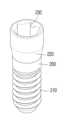
도 5는 본 발명의 어버트먼트 스크류를 도시한 사시도이다.
도 6 내지 도 8은 본 발명의 일 실시예에 따른 어버트먼트 조립체의 결합하는 과정을 나타내는 단면도이다.
도 9는 본 발명의 일 실시예에 따른 어버트먼트 조립체의 결합 단면도이다.
도 10은 본 발명의 링크의 다른 실시예를 도시한 사시도이다.1 is an exploded perspective view of an abutment assembly according to an embodiment of the present invention.
Figure 2 is an exploded cross-sectional view of an abutment assembly according to an embodiment of the present invention.
Figure 3 is a perspective view showing the base abutment of the present invention.
Figure 4 is a perspective view showing a link according to an embodiment of the present invention.
Figure 5 is a perspective view showing the abutment screw of the present invention.
Figures 6 to 8 are cross-sectional views showing the process of combining an abutment assembly according to an embodiment of the present invention.
Figure 9 is a combined cross-sectional view of the abutment assembly according to an embodiment of the present invention.
Figure 10 is a perspective view showing another embodiment of the link of the present invention.
이하에서는 첨부된 도면들을 참조하여 본 발명의 바람직한 실시예에 대해 상세하게 설명한다. 그러나 본 발명은 이하에서 개시되는 실시예에 한정되는 것이 아니라 서로 다른 다양한 형태로 구현될 것이며, 단지 본 실시예는 본 발명의 개시가 완전하도록 하며, 통상의 지식을 가진 자에게 발명의 범주를 완전하게 알려주기 위해 제공되는 것이다.Hereinafter, preferred embodiments of the present invention will be described in detail with reference to the attached drawings. However, the present invention is not limited to the embodiments disclosed below and will be implemented in various different forms, but the present embodiments only serve to ensure that the disclosure of the present invention is complete and to fully convey the scope of the invention to those skilled in the art. This is provided to inform you.
도 1은 본 발명의 일 실시예에 따른 어버트먼트 조립체의 분해 사시도이고, 도 2는 본 발명의 일 실시예에 따른 어버트먼트 조립체의 분해 단면도이다.Figure 1 is an exploded perspective view of an abutment assembly according to an embodiment of the present invention, and Figure 2 is an exploded cross-sectional view of an abutment assembly according to an embodiment of the present invention.
본 발명의 어버트먼트 조립체는 치조골에 매립되어 고정되는 픽스쳐(500)와, 상기 픽스쳐(500)에 체결되어 고정되는 베이스 어버트먼트(400)와, 상기 베이스 어버트먼트(400)에 결합되는 인공치아(100)와, 상기 인공치아의 위에서 삽입되어 결합되는 링크(300)와, 상기 베이스 어버트먼트의 암나사홈에 체결되는 스크류(200)를 포함한다.The abutment assembly of the present invention includes a fixture 500 that is embedded and fixed in the alveolar bone, a
상기 픽스쳐(500)는 치조골에 매립되는 인공 치근으로서, 이 픽스쳐(500)는 내주면에 암나사부(510)가 구비되고, 외주면에는 치조골에 매립되는 나사부가 형성된다.The fixture 500 is an artificial tooth root embedded in the alveolar bone. This fixture 500 is provided with a female thread portion 510 on its inner peripheral surface, and a threaded portion embedded in the alveolar bone is formed on its outer peripheral surface.
상기 나사부는 치조골 내부를 파고들면서 체결될 수 있도록 삼각나사로 형성될 수 있으며, 상기 픽스쳐(500)는 도 1에 도시한 바와 같이, 하부로 내려갈수록 외경이 점점 작아지는 형상을 가질 수 있다. 그러나, 픽스쳐(500)의 형상은 이에 한정하지 않으며 다양한 공지 기술이 적용되어도 무방하다.The screw portion may be formed as a triangular screw so that it can be fastened while digging into the inside of the alveolar bone, and the fixture 500 may have a shape in which the outer diameter becomes smaller as it goes downward, as shown in FIG. 1. However, the shape of the fixture 500 is not limited to this, and various known technologies may be applied.
또한, 상기 암나사부(510)에는 상기 베이스 어버트먼트(400)의 수나사부(410)가 체결되는데, 상기 베이스 어버트먼트(400)는 픽스쳐(500)의 암나사부(510)에 체결되는 수나사부(410)를 하부에 구비하고, 상부에는 체결홈(420)이 형성된다.In addition, the male threaded
상기 체결홈(420)은 상기 링크(300)와 결합하기 위한 다각홈(420b)과, 상기 스크류(200)의 나사산(210)과 결합하기 위한 스크류 체결용 암나사홈(420a)을 포함한다. 상기 암나사홈(420a)은 체결홈(420)의 하부에 형성되고 상기 다각홈(420b)은 체결홈(420)의 상부에 형성되는 형상을 갖는다.The
상기 다각홈(420b)은 하부의 암나사홈(420a) 내경보다 큰 내경을 갖도록 형성됨으로써, 하부와의 경계부가 단차지게 형성된다. 또한, 상기 링크(300)의 하단부는 상기 다각홈(420b)과 대응되는 형상의 다각형 결합부(340)가 형성되어 어버트먼트를 조립할 때 내부 체결형으로 상기 다각홈에 다각형 결합부(340)가 결합되어 방향성을 잡아주고, 상기 링크(300)가 베이스 어버트먼트(400)의 다각홈(420b)에 상대적으로 회전되지 않도록 결합될 수 있다.The polygonal groove 420b is formed to have an inner diameter larger than the inner diameter of the lower female screw groove 420a, so that the boundary with the lower portion is formed to be stepped. In addition, the lower end of the
여기서, 상기 다각형 결합부(340)는 육각 기둥 형태로 이루어지며, 상기 다각형 결합부(340)의 육각 기둥 형태에 대응하여 다각홈(420b)도 육각홈 형태로 이루어진다. 상기 다각홈(420b)은 육각 홈 형태로 한정되지 않고, 사각 홈 또는 팔각 홈 형태로 형성될 수도 있다. 이 경우, 상기 다각형 결합부(340)도 다각홈(420b)의 형태에 대응하여 사각 기둥 또는 팔각 기둥 형태로 이루어질 것이다.Here, the
도 3은 본 발명의 베이스 어버트먼트를 도시한 사시도이다.Figure 3 is a perspective view showing the base abutment of the present invention.
한편, 상기 베이스 어버트먼트(400)의 상부 외주면은 상단으로 갈수록 외경이 작아지는 일정 각도의 경사면(440)으로 형성되어 테이퍼(taper)진 원뿔대 형태를 가질 수 있으며, 인공치아(100)가 위에서 아래방향으로 끼워져 안착될 수 있다.Meanwhile, the upper outer peripheral surface of the
상기 베이스 어버트먼트(400)의 경사진 외주면은 인공치아가 씌워질 때 구강 내 저작 운동을 할 때 가해지는 측방 압력에 대응할 수 있도록 한다.The inclined outer peripheral surface of the
상기 경사면(440)이 형성된 베이스 어버트먼트(400)의 상부 중앙에 상기 다각홈(420b)과 암나사홈(420a)을 갖는 체결홈(420)이 형성된다.A
또한, 상기 베이스 어버트먼트(400)는 인공치아(100)가 안착되도록 지지하는 지지면(430)이 형성된다. 구체적으로, 베이스 어버트먼트의 경사면(440)의 하단부, 즉, 베이스 어버트먼트(400)의 중간에는 인공치아(100) 하단면을 안정적으로 지지할 수 있도록 지지면(430)이 형성되는 것이다. 이 지지면(430)은 수평면을 이루도록 형성되어 있으나, 이에 한정되지는 않으며 경우에 따라서 경사면을 이루도록 형성될 수도 있다.In addition, the
또한, 베이스 어버트먼트(400)의 지지면(430) 아래에는 외주면이 잇몸에 접촉하는 커프(cuff)가 형성된다. 상기 커프는 지지면(430)의 외측 주연부로부터 하방으로 이어지는 윤곽을 형성하는 부위로서, 사람의 잇몸이 접촉하는 부위이다.In addition, a cuff whose outer peripheral surface is in contact with the gum is formed below the
사람의 잇몸은 다양한 형태와 크기를 가지므로, 커프도 다양한 형태로 형성될 수 있으나, 통상 커프의 외주면은 기본적으로 이머전스 프로파일(emergence profile) 형성에 유리하도록 S자 곡면 형태로 형성되는 것이 바람직하다. 본 발명의 커프 외주면은 길쭉한 S자 형태의 곡면으로 형성되므로, 인상 채득으로 이머전스 프로파일을 매우 정확하게 형성할 수 있다.Since the human gums have various shapes and sizes, the cuff can be formed in various shapes, but it is generally preferable that the outer peripheral surface of the cuff is basically formed in an S-shaped curved shape to be advantageous in forming an emergence profile. Since the outer peripheral surface of the cuff of the present invention is formed as an elongated S-shaped curved surface, the emergence profile can be formed very accurately by taking an impression.
한편, 상기 인공치아(100)는 치과 기공소에서 CAD(Computer Aided Design) 또는 CAM(Computer Aided Manufacturing) 시스템을 통해 맞춤형으로 가공된다. 이 인공치아(100)는 지르코니아(zircornia) 재질로 이루어지는 것이 바람직하다. 인공치아(100)의 중심부에는 상기 베이스 어버트먼트(400)의 상부 외관에 대응되는 형상을 가지며 링크(300)의 단턱(330)에 걸려 결합가능한 내부 지지턱(130)을 갖는 인입홀(110)이 상하로 관통 형성되어 있다.Meanwhile, the
상기 인입홀(110)은 상하방향으로 3부분으로 구분된다. 그 하부는 상기 베이스 어버트먼트(400)의 경사면(440)에 대응되는 형상을 가지는 경사홀(110a)이 형성되며, 상기 경사홀(110a)의 상단에는 상기 링크(300)의 중간 외주면(370)과 접촉하여 체결이 가능한 내경을 가지는 중간홀(110b)이 형성되며, 상부에는 상기 링크(300)가 위에서 삽입되면 링크(300)의 상단 외주면(360)과 접촉하여 체결이 가능한 내경을 가지는 상부홀(110c)이 형성된다.The
상기 중간홀(110b)은 상부홀(110c) 보다 작은 내경을 갖도록 단차지게 형성되며, 상기 중간홀(110b)과 상부홀(110c) 사이에는 상기 링크(300)의 단턱(330)에 걸려 지지될 수 있도록 상기 내부 지지턱(130)이 형성된다.The middle hole 110b is formed to be stepped to have a smaller inner diameter than the upper hole 110c, and is supported by a
상기 상부홀(110c)은 링크(300) 보다 상하 길이가 더 크게 형성되어, 링크(300)가 상부홀에 완전히 삽입된 후에는 링크 위의 공간에 추가적으로 충진재가 채워질 수 있다.The upper hole 110c is formed to have a longer vertical length than the
도 4는 본 발명의 일 실시예에 따른 링크를 도시한 사시도로서, 본 발명에서는 상기 링크(300)가 상기 인공치아(100)의 위에서 상기 인입홀(110)에 삽입되어 결합되는 것을 특징으로 한다.Figure 4 is a perspective view showing a link according to an embodiment of the present invention. In the present invention, the
이와 같이, 본 발명은 링크가 위에서 삽입되어 나사체결되는 구조를 가짐으로써, 체결구조가 단순할 뿐 아니라 후술할 스크류(200) 체결방식에서, 스크류(200)가 링크(300)를 관통하여 베이스 어버트먼트(400)에 체결될 때 링크(300)가 인공치아(100)를 위에서 눌러 결합하기 때문에, 견고한 나사체결이 가능하다.In this way, the present invention has a structure in which the link is inserted from above and fastened with screws, so that not only is the fastening structure simple, but in the
이를 위해, 상기 링크(300)는 상기 인공치아의 지지턱(130)에 대응되는 형상의 단턱(330)이 형성되는 것이다.For this purpose, the
또한, 상기 링크(300)의 하부에는 베이스 어버트먼트(400)의 다각홈(420b)에 삽입되어 결합되는 다각형 결합부(340)가 형성된다. 이 다각형 결합부(340)는 베이스 어버트먼트(400)의 하부 전체가 아니라 하부 중에서 하단부의 외주면에만 형성될 수 있다. 즉, 하부의 상반부 외주면은 원기둥 형태로 이루어지어 중간 외주면(370)을 형성하고 그 하단부에만 다각형 결합부(340)가 형성될 수 있다.In addition, a
본 발명에서, 상기 링크(300)의 외주면에는 내부 방향성을 나타내주는 커팅부(350)가 형성될 수 있다. 상기 커팅부(350)는 다각형 결합부(340)와 동일한 방향의 형성되어 내부 방향성을 나타내주고 체결 시 방향 설정이 용이하게 할 수 있다.In the present invention, a cutting
상기 커팅부(350)가 본 발명의 실시예에 도시한 바와 같이, 1개 형성되는 경우, 상기 링크(300)의 상부는 D자 형태로 이루어지는데, 여기서, 상기 커팅부(350)는 링크의 외주면에 1개 이상 형성될 수도 있다.When the cutting
한편, 상기 링크(300)는 상기 스크류(200)가 삽입되어 결합하기 위한 결합홀(310)이 상하 관통형성된다.Meanwhile, the
상기 결합홀(310)은 상광하협(上廣下狹)의 형상으로 이루어질 수 있다. 즉, 결합홀(310)의 상부와 하부의 내경이 다르게 형성되며, 중앙부분에 하향 경사진 내주면 테이퍼부(320)가 형성되는 것이다. 이는 후술할 스크류(200)와의 결합 시 스크류 체결량에 따라 인공치아가 보다 더 견고하게 결합되도록 하기 위함으로, 상기 스크류(200)는 헤드부의 연결부위에 상기 링크의 내주면 테이퍼부(320)에 대응되는 형상의 외주면 테이퍼부(220)가 형성된다.The
이와 같은 링크와 스크류의 구조는 상기 스크류(200)가 나사산(210)을 따라 체결될수록 상기 스크류(200)의 외주면 테이퍼부(220)가 상기 링크(300)의 내주면 테이퍼부(320)와 결합되면서 링크를 위에서 아래방향으로 눌러주고, 상기 링크는 베이스 어버트먼트와의 사이 최대 간격에서 인공치아(100)를 더욱더 아래로 눌러주는 방식으로 결합시킬 수 있다.In this structure of the link and screw, as the
한편, 도 10은 본 발명의 링크의 다른 실시예를 도시한 사시도로서, 본 발명에서는 상기 다각형 결합부(340)와 커팅부(350)가 생략된 형상의 링크(600)도 적용 가능하다.Meanwhile, Figure 10 is a perspective view showing another embodiment of the link of the present invention. In the present invention, the link 600 of a shape in which the
즉, 상기 링크(600)는 커팅부가 생략되어 원기둥 형상을 갖는 상부 외주면(660)과, 상기 상부 외주면(660)과 단차지게 형성되어 상부 외주면(660) 보다 작은 직경을 갖는 중간 외주면(670)과, 다각형 결합부가 생략되어 원기둥 형상을 갖는 하부 외주면(640)을 갖는다.That is, the link 600 has an upper outer peripheral surface 660 that has a cylindrical shape with the cutting portion omitted, a middle outer peripheral surface 670 that is formed to be stepped from the upper outer peripheral surface 660 and has a smaller diameter than the upper outer peripheral surface 660, and , the polygonal coupling portion is omitted and has a lower outer peripheral surface 640 having a cylindrical shape.
이 경우에도, 상기 링크(600)의 상부 외주면(660)과 중간 외주면(670) 사이에는 상기 인공치아의 지지턱(130)에 대응되는 형상의 단턱이 형성되어 스크류(200)가 링크(600)를 관통하여 베이스 어버트먼트(400)에 체결될 때 링크(600)가 인공치아(100)를 위에서 눌러 결합할 수 있도록 한다. In this case as well, a step of a shape corresponding to the
또한, 본 발명의 다른 실시예의 링크는 하부에 다각형 결합부가 생략된 형태이므로, 이와 결합되는 베이스 어버트먼트(400)도 다각홈이 생략되어 링크(600)와 결합될 수 있도록 하는 것이 바람직하다.In addition, since the link of another embodiment of the present invention has a polygonal coupling part omitted at the bottom, it is preferable that the
도 5는 본 발명의 어버트먼트 스크류를 도시한 사시도이다.Figure 5 is a perspective view showing the abutment screw of the present invention.
상기 스크류(200)의 상면에는 육각렌치를 삽입하여 회전시킬 수 있도록 육각홈(230)이 형성되며, 중간에는 상기 테이퍼부(220)가 형성되고, 하단부에는 나사산(210)이 형성되어 베이스 어버트먼트(400)의 내주면에 형성된 암나사홈(420a)에 체결될 수 있다.A
한편, 본 발명은 상기 스크류(200)가 상기 베이스 어버트먼트(400)의 암나사홈(420a)에 결합되면 상기 스크류(200)의 헤드가 링크(300) 위로 올라오지 않아 공간확보가 용이한 구조를 갖는다.Meanwhile, in the present invention, when the
이러한 상기 스크류(200)는 헤드가 상기 링크 위에 올라오지 않도록 결합되어, 상기 인공치아(100)의 측방 압력을 스크류(200)가 받지 않고 상기 링크(300)와 베이스 어버트먼트(400)가 받아 버티게 되므로, 종래의 기술에 비해 측방 압력에 버티는 힘이 큰 장점이 있다.The
즉, 본 발명의 어버트먼트 조립체는 상기 스크류(200)의 헤드가 링크(300) 내부로 삽입되는 구조로 결합되므로, 상기 링크(300)의 외주면과 인공치아(100)의 인입홀(110)이 직접 접촉하여 측방 압력을 받을 수 있다.That is, the abutment assembly of the present invention is combined in a structure in which the head of the
구체적으로, 링크(300)의 상단 외주면(360)과 인공치아의 상부홀(110c)이 접촉가능하며, 링크(300)의 중간 외주면(370)과 인공치아의 중간홀(110b)이 접촉하여 체결될 수 있으므로, 상기 인공치아(100)의 측방 압력을 상기 링크(300)가 받아 버틸 수 있는 것이다.Specifically, the upper outer
여기서, 상기 링크(300)의 상단 외주면(360)과 인공치아의 상부홀(110c)이 접촉하거나, 링크(300)의 중간 외주면(370)과 인공치아의 중간홀(110b)이 접촉하여 체결되는 구조는 설계에 따라 선택적으로 이루어질 수 있다.Here, the upper outer
이와 같은 본 발명에서, 상기 베이스 어버트먼트(400)에는 힐링 캡(healing cap) 또는 스캔 바디(scan body)가 선택적으로 결합될 수 있다. 즉, 상기한 링크(300), 인공치아(100), 스크류(200)를 결합하는 대신, 픽스쳐(500)에 결합된 베이스 어버트먼트(400)에 힐링 캡을 체결하여 치은 힐링을 할 수 있고, 베이스 어버트먼트(400)에 스캔 바디를 체결하여 구강 스캐닝을 할 수도 있다.In the present invention, a healing cap or scan body may be selectively coupled to the
다음으로, 도 6 내지 도 8을 참조하여 본 발명의 일 실시예에 따른 어버트먼트 조립체의 결합하는 과정을 설명한다.Next, the process of combining the abutment assembly according to an embodiment of the present invention will be described with reference to FIGS. 6 to 8.
우선, 치조골에 상기 픽스쳐(500)를 식립하고 베이스 어버트먼트(400)를 픽스쳐(500)에 체결하는 과정은 일반적인 방법이 적용될 수 있되므로 상세한 설명은 생략한다.First, a general method can be applied to the process of installing the fixture 500 in the alveolar bone and fastening the
이후, 상기 베이스 어버트먼트(400)의 상부 경사면에 인공치아(100)를 위에서 아래방향으로 끼워 안착시킨 후, 도 6에서 보는 바와 같이, 상기 링크(300)를 베이스 어버트먼트(400)의 위에서 삽입하여 결합한다.Afterwards, the
이때, 상기 링크(300)의 외주면에는 내부 방향성을 나타내주는 커팅부(350)가 형성되어 있으므로, 체결 시 방향 설정이 용이하여 베이스 어버트먼트(400)의 다각홈(420b)에 링크(300)의 다각형 결합부(340)를 방향성을 잡아주면서 결합시킬 수 있다.At this time, since a cutting
이와 본 발명은 링크가 위에서 삽입되어 나사체결되는 구조를 가짐으로써, 체결구조가 단순할 뿐 아니라 상기 링크(300)의 단턱(330)이 인공치아(100)의 지지턱(130)을 눌러주게 되어, 인공치아(100)를 위에서 눌러 결합하는 구조이기 때문에 견고한 나사체결이 가능하다.This invention has a structure in which the link is inserted from above and fastened with a screw, so that not only is the fastening structure simple, but the
이후, 도 7에서와 같이, 상기 스크류(200)를 링크(300)의 결합홀(310)에 삽입하여 상기 결합홀(310)을 관통한 후 스크류를 회전시켜 베이스 어버트먼트(400)의 암나사홈(420a)에 체결한다(도 8).Thereafter, as shown in FIG. 7, the
이와 같은 링크와 스크류의 구조는 상기 스크류(200)가 나사산(210)을 따라 체결될수록 상기 스크류(200)의 외주면 테이퍼부(220)가 상기 링크(300)의 내주면 테이퍼부(320)와 결합되면서 링크를 위에서 아래방향으로 눌러주고, 상기 링크는 베이스 어버트먼트와의 사이 최대 간격에서 인공치아(100)를 더욱더 아래로 눌러주는 방식으로 결합시킬 수 있다.In this structure of the link and screw, as the
도 9는 본 발명의 일 실시예에 따른 어버트먼트 조립체의 결합 단면도이다.Figure 9 is a combined cross-sectional view of the abutment assembly according to an embodiment of the present invention.
본 발명은 상기 스크류(200)가 상기 베이스 어버트먼트(400)의 암나사홈(420a)에 결합되면 상기 스크류(200)의 헤드가 링크(300) 위로 올라오지 않아 공간확보가 용이하며, 상기 인공치아(100)의 측방 압력을 스크류(200)가 받지 않고 상기 링크(300)와 베이스 어버트먼트(400)가 받아 버티게 되므로, 종래의 기술에 비해 측방 압력에 버티는 힘이 크다.In the present invention, when the
이상에서는 본 발명의 실시예를 중심으로 설명하였지만, 본 발명이 속하는 기술분야에서 통상의 지식을 가진 기술자의 수준에서 다양한 변경이나 변형을 가할 수 있다. 이러한 변경과 변형은 본 발명이 제공하는 기술 사상의 범위를 벗어나지 않는 한 본 발명에 속한다고 할 수 있다. 따라서 본 발명의 권리범위는 이하에 기재되는 청구범위에 의해 판단되어야 할 것이다.Although the above description focuses on the embodiments of the present invention, various changes or modifications can be made at the level of a person skilled in the art in the technical field to which the present invention pertains. These changes and modifications can be said to belong to the present invention as long as they do not depart from the scope of the technical idea provided by the present invention. Therefore, the scope of rights of the present invention should be determined by the claims described below.
100: 인공치아110: 인입홀
110a: 경사홀110b: 중간홀
110c: 상부홀130: 내부 지지턱
200: 스크류
210: 나사산220: 외주면 테이퍼부
300: 링크330: 단턱
340: 다각형 결합부350: 커팅부
400: 베이스 어버트먼트420: 체결홈
420a: 암나사홈420b: 다각홈
430: 지지면500: 픽스쳐
510: 암나사부100: Artificial tooth 110: Inlet hole
110a: inclined hole 110b: middle hole
110c: upper hole 130: internal support jaw
200: screw
210: thread 220: tapered outer peripheral surface
300: Link 330: Step
340: polygonal coupling part 350: cutting part
400: Base abutment 420: Fastening groove
420a: Female thread groove 420b: Multi-angle groove
430: support surface 500: fixture
510: Female thread part
Claims (11)
Translated fromKorean상기 픽스쳐의 암나사부에 체결되는 수나사부를 구비하고, 상부에는 스크류 체결용 암나사홈을 포함하는 체결홈이 형성되는 베이스 어버트먼트;
상기 베이스 어버트먼트의 상부 외관에 대응되는 형상을 가지며 링크의 단턱에 걸려 결합가능한 내부 지지턱을 갖는 인입홀이 형성되는 인공치아;
상기 인공치아의 위에서 상기 인입홀에 삽입되어 결합되며, 상기 지지턱에 대응되는 형상의 단턱이 형성되는 링크; 및
상기 링크의 위에서 삽입되어 결합되고 상기 링크의 결합홀을 통과하여 상기 베이스 어버트먼트의 암나사홈에 체결되는 스크류;
를 포함하는 것을 특징으로 하는 어버트먼트 조립체.A fixture embedded and fixed in the alveolar bone and having a female thread portion;
A base abutment having a male threaded portion fastened to a female threaded portion of the fixture, and having a fastening groove including a female threaded groove for screw fastening formed on the upper portion;
An artificial tooth having a shape corresponding to the upper exterior of the base abutment and having an inlet hole formed with an internal support jaw that can be coupled to the step of the link;
a link that is inserted and coupled to the inlet hole on top of the artificial tooth and has a step of a shape corresponding to the support jaw; and
A screw that is inserted and coupled from above the link, passes through a coupling hole of the link, and is fastened to a female thread groove of the base abutment;
An abutment assembly comprising:
상기 베이스 어버트먼트의 상부 외주면은 상단으로 갈수록 외경이 작아지는 일정 각도의 경사면으로 형성되고, 상기 인공치아가 안착되도록 지지하는 지지면이 적어도 한 개 이상 형성되는 것을 특징으로 하는 치과 임플란트용 어버트먼트 조립체.In claim 1,
The upper outer peripheral surface of the base abutment is formed as an inclined surface at a certain angle whose outer diameter becomes smaller toward the top, and at least one support surface is formed to support the artificial tooth to be seated. ment assembly.
상기 베이스 어버트먼트는 상기 체결홈의 상부에 상기 링크와 결합하기 위한 다각홈이 형성되고, 상기 링크의 하부에는 상기 다각홈과 대응되는 형상의 다각형 결합부가 형성되어 상기 다각홈에 다각형 결합부가 결합되어 방향성을 잡아주는 것을 특징으로 하는 치과 임플란트용 어버트먼트 조립체.In claim 1,
The base abutment has a polygonal groove formed on the upper part of the fastening groove for coupling with the link, and a polygonal coupling part of a shape corresponding to the polygonal groove is formed on the lower part of the link, and the polygonal coupling part is coupled to the polygonal groove. An abutment assembly for dental implants, characterized in that it maintains direction.
상기 링크의 외주면에 다각형 결합부와 동일한 방향의 커팅부가 형성되어 내부 방향성을 나타내주고 체결 시 방향 설정이 용이한 것을 특징으로 하는 치과 임플란트용 어버트먼트 조립체.In claim 1 or claim 3,
An abutment assembly for a dental implant, characterized in that a cutting part in the same direction as the polygonal coupling part is formed on the outer peripheral surface of the link to indicate internal directionality and to facilitate direction setting when fastening.
상기 커팅부는 링크의 외주면에 적어도 1개 이상 형성되는 것을 특징으로 하는 치과 임플란트용 어버트먼트 조립체.In claim 4,
An abutment assembly for a dental implant, characterized in that at least one cutting portion is formed on the outer peripheral surface of the link.
상기 링크의 결합홀은 상광하협의 형상으로 이루어지며, 중앙부분에 경사진 내주면 테이퍼부가 형성되는 것을 특징으로 하는 치과 임플란트용 어버트먼트 조립체.In claim 1,
An abutment assembly for a dental implant, characterized in that the coupling hole of the link is formed in the shape of the upper and lower narrows, and a tapered portion of the inclined inner peripheral surface is formed in the central portion.
상기 스크류는 헤드부의 연결부위에 상기 링크의 내주면 테이퍼부에 대응되는 형상의 외주면 테이퍼부가 형성되어,
상기 스크류가 나사산을 따라 체결될수록 상기 스크류의 외주면 테이퍼부가 상기 링크를 위에서 아래방향으로 눌러주는 방식으로 결합되는 것을 특징으로 하는 치과 임플란트용 어버트먼트 조립체.In claim 5,
The screw has a tapered outer peripheral surface formed at the connection portion of the head portion, having a shape corresponding to the tapered inner peripheral surface of the link,
An abutment assembly for a dental implant, characterized in that as the screw is fastened along the thread, the tapered portion of the outer peripheral surface of the screw is coupled in such a way that the link is pressed from top to bottom.
상기 스크류가 상기 베이스 어버트먼트의 암나사홈에 결합되면 상기 스크류 헤드가 링크 위로 올라오지 않아 공간확보가 용이한 것을 특징으로 하는 치과 임플란트용 어버트먼트 조립체.In claim 1,
An abutment assembly for a dental implant, characterized in that when the screw is coupled to the female thread groove of the base abutment, the screw head does not rise above the link, making it easy to secure space.
상기 스크류 헤드가 상기 링크 위에 올라오지 않도록 결합되어, 상기 인공치아의 측방 압력을 상기 링크와 베이스 어버트먼트가 받아 버티는 것을 특징으로 하는 치과 임플란트용 어버트먼트 조립체.In claim 8,
An abutment assembly for a dental implant, characterized in that the screw head is coupled so as not to rise on the link, and the link and the base abutment receive and withstand the lateral pressure of the artificial tooth.
상기 베이스 어버트먼트에는 힐링 캡 또는 스캔 바디가 체결될 수 있는 것을 특징으로 하는 치과 임플란트용 어버트먼트 조립체.In claim 1,
An abutment assembly for a dental implant, characterized in that a healing cap or a scan body can be fastened to the base abutment.
상기 링크는 원기둥 형상의 상부 외주면과, 상기 상부 외주면과의 사이에 상기 단턱이 형성되어 상부 외주면 보다 작은 직경을 갖는 중간 외주면과, 상기 중간 외주면의 하부에 형성되며 원기둥 형상을 갖는 하부 외주면으로 이루어지는 외관 형상을 갖는 것을 특징으로 하는 치과 임플란트용 어버트먼트 조립체.
In claim 1,
The link has an exterior consisting of a cylindrical upper outer peripheral surface, a middle outer peripheral surface having a smaller diameter than the upper outer peripheral surface with the step formed between the upper outer peripheral surface, and a lower outer peripheral surface formed in a lower portion of the middle outer peripheral surface and having a cylindrical shape. An abutment assembly for dental implants, characterized in that it has a shape.
Priority Applications (1)
| Application Number | Priority Date | Filing Date | Title |
|---|---|---|---|
| KR1020220061755AKR102831108B1 (en) | 2022-05-20 | 2022-05-20 | Abutment Assembly for Dental Implants |
Applications Claiming Priority (1)
| Application Number | Priority Date | Filing Date | Title |
|---|---|---|---|
| KR1020220061755AKR102831108B1 (en) | 2022-05-20 | 2022-05-20 | Abutment Assembly for Dental Implants |
Publications (2)
| Publication Number | Publication Date |
|---|---|
| KR20230162851Atrue KR20230162851A (en) | 2023-11-29 |
| KR102831108B1 KR102831108B1 (en) | 2025-07-09 |
Family
ID=88969395
Family Applications (1)
| Application Number | Title | Priority Date | Filing Date |
|---|---|---|---|
| KR1020220061755AActiveKR102831108B1 (en) | 2022-05-20 | 2022-05-20 | Abutment Assembly for Dental Implants |
Country Status (1)
| Country | Link |
|---|---|
| KR (1) | KR102831108B1 (en) |
Cited By (2)
| Publication number | Priority date | Publication date | Assignee | Title |
|---|---|---|---|---|
| KR102784585B1 (en)* | 2024-05-31 | 2025-03-21 | 주식회사 하이니스 | One body Fixture and Abutment Assembly comprising the same |
| WO2025135520A1 (en)* | 2023-12-19 | 2025-06-26 | 주식회사지온 | Dental abutment assembly |
Citations (8)
| Publication number | Priority date | Publication date | Assignee | Title |
|---|---|---|---|---|
| KR20040034874A (en) | 2002-10-17 | 2004-04-29 | (주) 코웰메디 | Abutment of a dental implant for a crown |
| KR20090048078A (en) | 2007-11-09 | 2009-05-13 | 주식회사 쿠보텍 | Dental implant device |
| KR101768410B1 (en)* | 2017-01-18 | 2017-08-17 | 박건제 | Locking link and assembling method thereof |
| KR101881421B1 (en)* | 2018-04-13 | 2018-07-24 | 주식회사 하이니스 | Abutment assembly |
| KR20200098434A (en)* | 2020-03-20 | 2020-08-20 | 최종훈 | Loose type Dental implant |
| KR102198237B1 (en)* | 2020-01-14 | 2021-01-05 | (주) 코웰메디 | Cenemtless dental implant using elastic bushing |
| KR102198234B1 (en)* | 2019-12-27 | 2021-01-05 | (주) 코웰메디 | Cenemtless dental implant |
| KR102387700B1 (en)* | 2020-04-24 | 2022-04-15 | 이해용 | Coupling Assembly for Dental Implant Prosthesis |
- 2022
- 2022-05-20KRKR1020220061755Apatent/KR102831108B1/enactiveActive
Patent Citations (8)
| Publication number | Priority date | Publication date | Assignee | Title |
|---|---|---|---|---|
| KR20040034874A (en) | 2002-10-17 | 2004-04-29 | (주) 코웰메디 | Abutment of a dental implant for a crown |
| KR20090048078A (en) | 2007-11-09 | 2009-05-13 | 주식회사 쿠보텍 | Dental implant device |
| KR101768410B1 (en)* | 2017-01-18 | 2017-08-17 | 박건제 | Locking link and assembling method thereof |
| KR101881421B1 (en)* | 2018-04-13 | 2018-07-24 | 주식회사 하이니스 | Abutment assembly |
| KR102198234B1 (en)* | 2019-12-27 | 2021-01-05 | (주) 코웰메디 | Cenemtless dental implant |
| KR102198237B1 (en)* | 2020-01-14 | 2021-01-05 | (주) 코웰메디 | Cenemtless dental implant using elastic bushing |
| KR20200098434A (en)* | 2020-03-20 | 2020-08-20 | 최종훈 | Loose type Dental implant |
| KR102387700B1 (en)* | 2020-04-24 | 2022-04-15 | 이해용 | Coupling Assembly for Dental Implant Prosthesis |
Cited By (2)
| Publication number | Priority date | Publication date | Assignee | Title |
|---|---|---|---|---|
| WO2025135520A1 (en)* | 2023-12-19 | 2025-06-26 | 주식회사지온 | Dental abutment assembly |
| KR102784585B1 (en)* | 2024-05-31 | 2025-03-21 | 주식회사 하이니스 | One body Fixture and Abutment Assembly comprising the same |
Also Published As
| Publication number | Publication date |
|---|---|
| KR102831108B1 (en) | 2025-07-09 |
Similar Documents
| Publication | Publication Date | Title |
|---|---|---|
| KR101881421B1 (en) | Abutment assembly | |
| KR102551331B1 (en) | Abutment assembly | |
| US6273720B1 (en) | Dental implant system | |
| US6431866B2 (en) | Heal in-place abutment system | |
| US9314318B2 (en) | Dental anchor apparatus and method | |
| KR101966407B1 (en) | Abutment assembly | |
| US20060228672A1 (en) | Transfer coping for dental implants | |
| US20060263747A1 (en) | Healing cap for dental implants | |
| KR20230162851A (en) | Abutment Assembly for Dental Implants | |
| RU2440061C2 (en) | Dental implant with internal cone | |
| KR101106161B1 (en) | Implant device with a secure connection between abutment and zirconia cap | |
| KR101997044B1 (en) | Integrated implant and method of making the same | |
| KR102480664B1 (en) | Non-adhesive fixture integral abutment and implnat having the same | |
| US8998612B2 (en) | Dental implant fixture and implant system having the same | |
| KR101025225B1 (en) | Dental Implant Fixtures | |
| KR100779227B1 (en) | Dental implant | |
| KR20220140286A (en) | Washer of the abutment assembly | |
| KR20200014558A (en) | Abutment assembly | |
| KR20240179022A (en) | Multi-unit dental implant | |
| KR20190122285A (en) | Dental Implant | |
| KR101049270B1 (en) | Fixture for double-tapered implants | |
| KR20190107228A (en) | customized dental implant for immediate implanting after extraction of tooth | |
| KR102356447B1 (en) | Abutment assembly and method for assembling the same | |
| KR100928019B1 (en) | Implant device consisting of wide and mini implants | |
| KR200374841Y1 (en) | Dental implant system |
Legal Events
| Date | Code | Title | Description |
|---|---|---|---|
| PA0109 | Patent application | St.27 status event code:A-0-1-A10-A12-nap-PA0109 | |
| PA0201 | Request for examination | St.27 status event code:A-1-2-D10-D11-exm-PA0201 | |
| D13-X000 | Search requested | St.27 status event code:A-1-2-D10-D13-srh-X000 | |
| D14-X000 | Search report completed | St.27 status event code:A-1-2-D10-D14-srh-X000 | |
| PG1501 | Laying open of application | St.27 status event code:A-1-1-Q10-Q12-nap-PG1501 | |
| E902 | Notification of reason for refusal | ||
| PE0902 | Notice of grounds for rejection | St.27 status event code:A-1-2-D10-D21-exm-PE0902 | |
| E13-X000 | Pre-grant limitation requested | St.27 status event code:A-2-3-E10-E13-lim-X000 | |
| P11-X000 | Amendment of application requested | St.27 status event code:A-2-2-P10-P11-nap-X000 | |
| P13-X000 | Application amended | St.27 status event code:A-2-2-P10-P13-nap-X000 | |
| E14-X000 | Pre-grant third party observation filed | St.27 status event code:A-2-3-E10-E14-opp-X000 | |
| E902 | Notification of reason for refusal | ||
| PE0902 | Notice of grounds for rejection | St.27 status event code:A-1-2-D10-D21-exm-PE0902 | |
| E13-X000 | Pre-grant limitation requested | St.27 status event code:A-2-3-E10-E13-lim-X000 | |
| P11-X000 | Amendment of application requested | St.27 status event code:A-2-2-P10-P11-nap-X000 | |
| P13-X000 | Application amended | St.27 status event code:A-2-2-P10-P13-nap-X000 | |
| E701 | Decision to grant or registration of patent right | ||
| PE0701 | Decision of registration | St.27 status event code:A-1-2-D10-D22-exm-PE0701 | |
| GRNT | Written decision to grant | ||
| PR0701 | Registration of establishment | St.27 status event code:A-2-4-F10-F11-exm-PR0701 | |
| PR1002 | Payment of registration fee | St.27 status event code:A-2-2-U10-U11-oth-PR1002 | |
| PG1601 | Publication of registration | St.27 status event code:A-4-4-Q10-Q13-nap-PG1601 |