KR20230158053A - TRIPOLAR electrode arrangement for electrostatic chucks - Google Patents
TRIPOLAR electrode arrangement for electrostatic chucksDownload PDFInfo
- Publication number
- KR20230158053A KR20230158053AKR1020237035202AKR20237035202AKR20230158053AKR 20230158053 AKR20230158053 AKR 20230158053AKR 1020237035202 AKR1020237035202 AKR 1020237035202AKR 20237035202 AKR20237035202 AKR 20237035202AKR 20230158053 AKR20230158053 AKR 20230158053A
- Authority
- KR
- South Korea
- Prior art keywords
- electrodes
- pedestal
- showerhead
- electrode
- polarity
- Prior art date
- Legal status (The legal status is an assumption and is not a legal conclusion. Google has not performed a legal analysis and makes no representation as to the accuracy of the status listed.)
- Pending
Links
- 239000000758substrateSubstances0.000claimsabstractdescription238
- NJPPVKZQTLUDBO-UHFFFAOYSA-NnovaluronChemical compoundC1=C(Cl)C(OC(F)(F)C(OC(F)(F)F)F)=CC=C1NC(=O)NC(=O)C1=C(F)C=CC=C1FNJPPVKZQTLUDBO-UHFFFAOYSA-N0.000claimsabstractdescription198
- 238000012545processingMethods0.000claimsabstractdescription80
- 238000005259measurementMethods0.000claimsdescription142
- 230000010363phase shiftEffects0.000claimsdescription15
- 239000000463materialSubstances0.000claimsdescription8
- 239000002178crystalline materialSubstances0.000claimsdescription3
- 238000000034methodMethods0.000description62
- 230000008569processEffects0.000description36
- 238000006073displacement reactionMethods0.000description16
- 239000007789gasSubstances0.000description15
- 235000012431wafersNutrition0.000description14
- 239000003989dielectric materialSubstances0.000description10
- 239000004065semiconductorSubstances0.000description10
- 238000004519manufacturing processMethods0.000description9
- 239000002826coolantSubstances0.000description8
- 230000007246mechanismEffects0.000description8
- 230000010355oscillationEffects0.000description8
- 238000000231atomic layer depositionMethods0.000description7
- 239000003990capacitorSubstances0.000description7
- 238000012546transferMethods0.000description7
- 230000008859changeEffects0.000description6
- 239000000523sampleSubstances0.000description6
- 230000000903blocking effectEffects0.000description5
- 239000004020conductorSubstances0.000description5
- 238000005530etchingMethods0.000description5
- 238000010438heat treatmentMethods0.000description5
- 238000000429assemblyMethods0.000description4
- 230000000712assemblyEffects0.000description4
- 238000000151depositionMethods0.000description4
- 230000008021depositionEffects0.000description4
- 230000006870functionEffects0.000description4
- 238000005240physical vapour depositionMethods0.000description4
- 238000000623plasma-assisted chemical vapour depositionMethods0.000description4
- 238000001816coolingMethods0.000description3
- 238000010586diagramMethods0.000description3
- 238000009826distributionMethods0.000description3
- 239000002184metalSubstances0.000description3
- 229910052751metalInorganic materials0.000description3
- 239000002243precursorSubstances0.000description3
- VYPSYNLAJGMNEJ-UHFFFAOYSA-NSilicium dioxideChemical compoundO=[Si]=OVYPSYNLAJGMNEJ-UHFFFAOYSA-N0.000description2
- 230000009471actionEffects0.000description2
- 238000003491arrayMethods0.000description2
- 238000006243chemical reactionMethods0.000description2
- 238000004140cleaningMethods0.000description2
- 230000008878couplingEffects0.000description2
- 238000010168coupling processMethods0.000description2
- 238000005859coupling reactionMethods0.000description2
- 230000007423decreaseEffects0.000description2
- 230000007547defectEffects0.000description2
- 239000000203mixtureSubstances0.000description2
- -1on the lift pins)Chemical compound0.000description2
- 238000001020plasma etchingMethods0.000description2
- 229910052710siliconInorganic materials0.000description2
- 239000010703siliconSubstances0.000description2
- 229910052782aluminiumInorganic materials0.000description1
- XAGFODPZIPBFFR-UHFFFAOYSA-NaluminiumChemical compound[Al]XAGFODPZIPBFFR-UHFFFAOYSA-N0.000description1
- 238000000277atomic layer chemical vapour depositionMethods0.000description1
- 230000008901benefitEffects0.000description1
- 238000003486chemical etchingMethods0.000description1
- 238000005229chemical vapour depositionMethods0.000description1
- 238000004891communicationMethods0.000description1
- 230000006866deteriorationEffects0.000description1
- 239000012530fluidSubstances0.000description1
- 239000011521glassSubstances0.000description1
- 238000002847impedance measurementMethods0.000description1
- 238000011065in-situ storageMethods0.000description1
- 238000005468ion implantationMethods0.000description1
- 238000002955isolationMethods0.000description1
- 238000002372labellingMethods0.000description1
- 239000010410layerSubstances0.000description1
- 150000002739metalsChemical class0.000description1
- 238000012986modificationMethods0.000description1
- 230000004048modificationEffects0.000description1
- 230000003287optical effectEffects0.000description1
- 238000007747platingMethods0.000description1
- 238000010926purgeMethods0.000description1
- 239000000376reactantSubstances0.000description1
- 238000009877renderingMethods0.000description1
- 229910052594sapphireInorganic materials0.000description1
- 239000010980sapphireSubstances0.000description1
- 230000035945sensitivityEffects0.000description1
- 235000012239silicon dioxideNutrition0.000description1
- 239000000377silicon dioxideSubstances0.000description1
- 238000004544sputter depositionMethods0.000description1
- 238000006467substitution reactionMethods0.000description1
- 238000007740vapor depositionMethods0.000description1
Images


Classifications
- H—ELECTRICITY
- H01—ELECTRIC ELEMENTS
- H01J—ELECTRIC DISCHARGE TUBES OR DISCHARGE LAMPS
- H01J37/00—Discharge tubes with provision for introducing objects or material to be exposed to the discharge, e.g. for the purpose of examination or processing thereof
- H01J37/32—Gas-filled discharge tubes
- H01J37/32431—Constructional details of the reactor
- H01J37/32532—Electrodes
- H01J37/32568—Relative arrangement or disposition of electrodes; moving means
- C—CHEMISTRY; METALLURGY
- C23—COATING METALLIC MATERIAL; COATING MATERIAL WITH METALLIC MATERIAL; CHEMICAL SURFACE TREATMENT; DIFFUSION TREATMENT OF METALLIC MATERIAL; COATING BY VACUUM EVAPORATION, BY SPUTTERING, BY ION IMPLANTATION OR BY CHEMICAL VAPOUR DEPOSITION, IN GENERAL; INHIBITING CORROSION OF METALLIC MATERIAL OR INCRUSTATION IN GENERAL
- C23C—COATING METALLIC MATERIAL; COATING MATERIAL WITH METALLIC MATERIAL; SURFACE TREATMENT OF METALLIC MATERIAL BY DIFFUSION INTO THE SURFACE, BY CHEMICAL CONVERSION OR SUBSTITUTION; COATING BY VACUUM EVAPORATION, BY SPUTTERING, BY ION IMPLANTATION OR BY CHEMICAL VAPOUR DEPOSITION, IN GENERAL
- C23C14/00—Coating by vacuum evaporation, by sputtering or by ion implantation of the coating forming material
- C23C14/22—Coating by vacuum evaporation, by sputtering or by ion implantation of the coating forming material characterised by the process of coating
- C23C14/34—Sputtering
- C—CHEMISTRY; METALLURGY
- C23—COATING METALLIC MATERIAL; COATING MATERIAL WITH METALLIC MATERIAL; CHEMICAL SURFACE TREATMENT; DIFFUSION TREATMENT OF METALLIC MATERIAL; COATING BY VACUUM EVAPORATION, BY SPUTTERING, BY ION IMPLANTATION OR BY CHEMICAL VAPOUR DEPOSITION, IN GENERAL; INHIBITING CORROSION OF METALLIC MATERIAL OR INCRUSTATION IN GENERAL
- C23C—COATING METALLIC MATERIAL; COATING MATERIAL WITH METALLIC MATERIAL; SURFACE TREATMENT OF METALLIC MATERIAL BY DIFFUSION INTO THE SURFACE, BY CHEMICAL CONVERSION OR SUBSTITUTION; COATING BY VACUUM EVAPORATION, BY SPUTTERING, BY ION IMPLANTATION OR BY CHEMICAL VAPOUR DEPOSITION, IN GENERAL
- C23C14/00—Coating by vacuum evaporation, by sputtering or by ion implantation of the coating forming material
- C23C14/22—Coating by vacuum evaporation, by sputtering or by ion implantation of the coating forming material characterised by the process of coating
- C23C14/50—Substrate holders
- C—CHEMISTRY; METALLURGY
- C23—COATING METALLIC MATERIAL; COATING MATERIAL WITH METALLIC MATERIAL; CHEMICAL SURFACE TREATMENT; DIFFUSION TREATMENT OF METALLIC MATERIAL; COATING BY VACUUM EVAPORATION, BY SPUTTERING, BY ION IMPLANTATION OR BY CHEMICAL VAPOUR DEPOSITION, IN GENERAL; INHIBITING CORROSION OF METALLIC MATERIAL OR INCRUSTATION IN GENERAL
- C23C—COATING METALLIC MATERIAL; COATING MATERIAL WITH METALLIC MATERIAL; SURFACE TREATMENT OF METALLIC MATERIAL BY DIFFUSION INTO THE SURFACE, BY CHEMICAL CONVERSION OR SUBSTITUTION; COATING BY VACUUM EVAPORATION, BY SPUTTERING, BY ION IMPLANTATION OR BY CHEMICAL VAPOUR DEPOSITION, IN GENERAL
- C23C14/00—Coating by vacuum evaporation, by sputtering or by ion implantation of the coating forming material
- C23C14/22—Coating by vacuum evaporation, by sputtering or by ion implantation of the coating forming material characterised by the process of coating
- C23C14/54—Controlling or regulating the coating process
- C—CHEMISTRY; METALLURGY
- C23—COATING METALLIC MATERIAL; COATING MATERIAL WITH METALLIC MATERIAL; CHEMICAL SURFACE TREATMENT; DIFFUSION TREATMENT OF METALLIC MATERIAL; COATING BY VACUUM EVAPORATION, BY SPUTTERING, BY ION IMPLANTATION OR BY CHEMICAL VAPOUR DEPOSITION, IN GENERAL; INHIBITING CORROSION OF METALLIC MATERIAL OR INCRUSTATION IN GENERAL
- C23C—COATING METALLIC MATERIAL; COATING MATERIAL WITH METALLIC MATERIAL; SURFACE TREATMENT OF METALLIC MATERIAL BY DIFFUSION INTO THE SURFACE, BY CHEMICAL CONVERSION OR SUBSTITUTION; COATING BY VACUUM EVAPORATION, BY SPUTTERING, BY ION IMPLANTATION OR BY CHEMICAL VAPOUR DEPOSITION, IN GENERAL
- C23C16/00—Chemical coating by decomposition of gaseous compounds, without leaving reaction products of surface material in the coating, i.e. chemical vapour deposition [CVD] processes
- C23C16/44—Chemical coating by decomposition of gaseous compounds, without leaving reaction products of surface material in the coating, i.e. chemical vapour deposition [CVD] processes characterised by the method of coating
- C23C16/455—Chemical coating by decomposition of gaseous compounds, without leaving reaction products of surface material in the coating, i.e. chemical vapour deposition [CVD] processes characterised by the method of coating characterised by the method used for introducing gases into reaction chamber or for modifying gas flows in reaction chamber
- C23C16/45523—Pulsed gas flow or change of composition over time
- C23C16/45525—Atomic layer deposition [ALD]
- C23C16/45527—Atomic layer deposition [ALD] characterized by the ALD cycle, e.g. different flows or temperatures during half-reactions, unusual pulsing sequence, use of precursor mixtures or auxiliary reactants or activations
- C23C16/45536—Use of plasma, radiation or electromagnetic fields
- C—CHEMISTRY; METALLURGY
- C23—COATING METALLIC MATERIAL; COATING MATERIAL WITH METALLIC MATERIAL; CHEMICAL SURFACE TREATMENT; DIFFUSION TREATMENT OF METALLIC MATERIAL; COATING BY VACUUM EVAPORATION, BY SPUTTERING, BY ION IMPLANTATION OR BY CHEMICAL VAPOUR DEPOSITION, IN GENERAL; INHIBITING CORROSION OF METALLIC MATERIAL OR INCRUSTATION IN GENERAL
- C23C—COATING METALLIC MATERIAL; COATING MATERIAL WITH METALLIC MATERIAL; SURFACE TREATMENT OF METALLIC MATERIAL BY DIFFUSION INTO THE SURFACE, BY CHEMICAL CONVERSION OR SUBSTITUTION; COATING BY VACUUM EVAPORATION, BY SPUTTERING, BY ION IMPLANTATION OR BY CHEMICAL VAPOUR DEPOSITION, IN GENERAL
- C23C16/00—Chemical coating by decomposition of gaseous compounds, without leaving reaction products of surface material in the coating, i.e. chemical vapour deposition [CVD] processes
- C23C16/44—Chemical coating by decomposition of gaseous compounds, without leaving reaction products of surface material in the coating, i.e. chemical vapour deposition [CVD] processes characterised by the method of coating
- C23C16/455—Chemical coating by decomposition of gaseous compounds, without leaving reaction products of surface material in the coating, i.e. chemical vapour deposition [CVD] processes characterised by the method of coating characterised by the method used for introducing gases into reaction chamber or for modifying gas flows in reaction chamber
- C23C16/45523—Pulsed gas flow or change of composition over time
- C23C16/45525—Atomic layer deposition [ALD]
- C23C16/45544—Atomic layer deposition [ALD] characterized by the apparatus
- C—CHEMISTRY; METALLURGY
- C23—COATING METALLIC MATERIAL; COATING MATERIAL WITH METALLIC MATERIAL; CHEMICAL SURFACE TREATMENT; DIFFUSION TREATMENT OF METALLIC MATERIAL; COATING BY VACUUM EVAPORATION, BY SPUTTERING, BY ION IMPLANTATION OR BY CHEMICAL VAPOUR DEPOSITION, IN GENERAL; INHIBITING CORROSION OF METALLIC MATERIAL OR INCRUSTATION IN GENERAL
- C23C—COATING METALLIC MATERIAL; COATING MATERIAL WITH METALLIC MATERIAL; SURFACE TREATMENT OF METALLIC MATERIAL BY DIFFUSION INTO THE SURFACE, BY CHEMICAL CONVERSION OR SUBSTITUTION; COATING BY VACUUM EVAPORATION, BY SPUTTERING, BY ION IMPLANTATION OR BY CHEMICAL VAPOUR DEPOSITION, IN GENERAL
- C23C16/00—Chemical coating by decomposition of gaseous compounds, without leaving reaction products of surface material in the coating, i.e. chemical vapour deposition [CVD] processes
- C23C16/44—Chemical coating by decomposition of gaseous compounds, without leaving reaction products of surface material in the coating, i.e. chemical vapour deposition [CVD] processes characterised by the method of coating
- C23C16/455—Chemical coating by decomposition of gaseous compounds, without leaving reaction products of surface material in the coating, i.e. chemical vapour deposition [CVD] processes characterised by the method of coating characterised by the method used for introducing gases into reaction chamber or for modifying gas flows in reaction chamber
- C23C16/45563—Gas nozzles
- C23C16/45565—Shower nozzles
- C—CHEMISTRY; METALLURGY
- C23—COATING METALLIC MATERIAL; COATING MATERIAL WITH METALLIC MATERIAL; CHEMICAL SURFACE TREATMENT; DIFFUSION TREATMENT OF METALLIC MATERIAL; COATING BY VACUUM EVAPORATION, BY SPUTTERING, BY ION IMPLANTATION OR BY CHEMICAL VAPOUR DEPOSITION, IN GENERAL; INHIBITING CORROSION OF METALLIC MATERIAL OR INCRUSTATION IN GENERAL
- C23C—COATING METALLIC MATERIAL; COATING MATERIAL WITH METALLIC MATERIAL; SURFACE TREATMENT OF METALLIC MATERIAL BY DIFFUSION INTO THE SURFACE, BY CHEMICAL CONVERSION OR SUBSTITUTION; COATING BY VACUUM EVAPORATION, BY SPUTTERING, BY ION IMPLANTATION OR BY CHEMICAL VAPOUR DEPOSITION, IN GENERAL
- C23C16/00—Chemical coating by decomposition of gaseous compounds, without leaving reaction products of surface material in the coating, i.e. chemical vapour deposition [CVD] processes
- C23C16/44—Chemical coating by decomposition of gaseous compounds, without leaving reaction products of surface material in the coating, i.e. chemical vapour deposition [CVD] processes characterised by the method of coating
- C23C16/458—Chemical coating by decomposition of gaseous compounds, without leaving reaction products of surface material in the coating, i.e. chemical vapour deposition [CVD] processes characterised by the method of coating characterised by the method used for supporting substrates in the reaction chamber
- C23C16/4582—Rigid and flat substrates, e.g. plates or discs
- C23C16/4583—Rigid and flat substrates, e.g. plates or discs the substrate being supported substantially horizontally
- C—CHEMISTRY; METALLURGY
- C23—COATING METALLIC MATERIAL; COATING MATERIAL WITH METALLIC MATERIAL; CHEMICAL SURFACE TREATMENT; DIFFUSION TREATMENT OF METALLIC MATERIAL; COATING BY VACUUM EVAPORATION, BY SPUTTERING, BY ION IMPLANTATION OR BY CHEMICAL VAPOUR DEPOSITION, IN GENERAL; INHIBITING CORROSION OF METALLIC MATERIAL OR INCRUSTATION IN GENERAL
- C23C—COATING METALLIC MATERIAL; COATING MATERIAL WITH METALLIC MATERIAL; SURFACE TREATMENT OF METALLIC MATERIAL BY DIFFUSION INTO THE SURFACE, BY CHEMICAL CONVERSION OR SUBSTITUTION; COATING BY VACUUM EVAPORATION, BY SPUTTERING, BY ION IMPLANTATION OR BY CHEMICAL VAPOUR DEPOSITION, IN GENERAL
- C23C16/00—Chemical coating by decomposition of gaseous compounds, without leaving reaction products of surface material in the coating, i.e. chemical vapour deposition [CVD] processes
- C23C16/44—Chemical coating by decomposition of gaseous compounds, without leaving reaction products of surface material in the coating, i.e. chemical vapour deposition [CVD] processes characterised by the method of coating
- C23C16/50—Chemical coating by decomposition of gaseous compounds, without leaving reaction products of surface material in the coating, i.e. chemical vapour deposition [CVD] processes characterised by the method of coating using electric discharges
- C—CHEMISTRY; METALLURGY
- C23—COATING METALLIC MATERIAL; COATING MATERIAL WITH METALLIC MATERIAL; CHEMICAL SURFACE TREATMENT; DIFFUSION TREATMENT OF METALLIC MATERIAL; COATING BY VACUUM EVAPORATION, BY SPUTTERING, BY ION IMPLANTATION OR BY CHEMICAL VAPOUR DEPOSITION, IN GENERAL; INHIBITING CORROSION OF METALLIC MATERIAL OR INCRUSTATION IN GENERAL
- C23C—COATING METALLIC MATERIAL; COATING MATERIAL WITH METALLIC MATERIAL; SURFACE TREATMENT OF METALLIC MATERIAL BY DIFFUSION INTO THE SURFACE, BY CHEMICAL CONVERSION OR SUBSTITUTION; COATING BY VACUUM EVAPORATION, BY SPUTTERING, BY ION IMPLANTATION OR BY CHEMICAL VAPOUR DEPOSITION, IN GENERAL
- C23C16/00—Chemical coating by decomposition of gaseous compounds, without leaving reaction products of surface material in the coating, i.e. chemical vapour deposition [CVD] processes
- C23C16/44—Chemical coating by decomposition of gaseous compounds, without leaving reaction products of surface material in the coating, i.e. chemical vapour deposition [CVD] processes characterised by the method of coating
- C23C16/52—Controlling or regulating the coating process
- H—ELECTRICITY
- H01—ELECTRIC ELEMENTS
- H01J—ELECTRIC DISCHARGE TUBES OR DISCHARGE LAMPS
- H01J37/00—Discharge tubes with provision for introducing objects or material to be exposed to the discharge, e.g. for the purpose of examination or processing thereof
- H01J37/32—Gas-filled discharge tubes
- H01J37/32431—Constructional details of the reactor
- H01J37/3244—Gas supply means
- H—ELECTRICITY
- H01—ELECTRIC ELEMENTS
- H01J—ELECTRIC DISCHARGE TUBES OR DISCHARGE LAMPS
- H01J37/00—Discharge tubes with provision for introducing objects or material to be exposed to the discharge, e.g. for the purpose of examination or processing thereof
- H01J37/32—Gas-filled discharge tubes
- H01J37/32431—Constructional details of the reactor
- H01J37/32532—Electrodes
- H01J37/32541—Shape
- H—ELECTRICITY
- H01—ELECTRIC ELEMENTS
- H01J—ELECTRIC DISCHARGE TUBES OR DISCHARGE LAMPS
- H01J37/00—Discharge tubes with provision for introducing objects or material to be exposed to the discharge, e.g. for the purpose of examination or processing thereof
- H01J37/32—Gas-filled discharge tubes
- H01J37/32431—Constructional details of the reactor
- H01J37/32532—Electrodes
- H01J37/32577—Electrical connecting means
- H—ELECTRICITY
- H01—ELECTRIC ELEMENTS
- H01J—ELECTRIC DISCHARGE TUBES OR DISCHARGE LAMPS
- H01J37/00—Discharge tubes with provision for introducing objects or material to be exposed to the discharge, e.g. for the purpose of examination or processing thereof
- H01J37/32—Gas-filled discharge tubes
- H01J37/32431—Constructional details of the reactor
- H01J37/32715—Workpiece holder
- H—ELECTRICITY
- H01—ELECTRIC ELEMENTS
- H01J—ELECTRIC DISCHARGE TUBES OR DISCHARGE LAMPS
- H01J37/00—Discharge tubes with provision for introducing objects or material to be exposed to the discharge, e.g. for the purpose of examination or processing thereof
- H01J37/32—Gas-filled discharge tubes
- H01J37/32917—Plasma diagnostics
- H01J37/32935—Monitoring and controlling tubes by information coming from the object and/or discharge
- H—ELECTRICITY
- H01—ELECTRIC ELEMENTS
- H01L—SEMICONDUCTOR DEVICES NOT COVERED BY CLASS H10
- H01L21/00—Processes or apparatus adapted for the manufacture or treatment of semiconductor or solid state devices or of parts thereof
- H01L21/67—Apparatus specially adapted for handling semiconductor or electric solid state devices during manufacture or treatment thereof; Apparatus specially adapted for handling wafers during manufacture or treatment of semiconductor or electric solid state devices or components ; Apparatus not specifically provided for elsewhere
- H01L21/67005—Apparatus not specifically provided for elsewhere
- H01L21/67011—Apparatus for manufacture or treatment
- H01L21/67017—Apparatus for fluid treatment
- H01L21/67063—Apparatus for fluid treatment for etching
- H—ELECTRICITY
- H01—ELECTRIC ELEMENTS
- H01L—SEMICONDUCTOR DEVICES NOT COVERED BY CLASS H10
- H01L21/00—Processes or apparatus adapted for the manufacture or treatment of semiconductor or solid state devices or of parts thereof
- H01L21/67—Apparatus specially adapted for handling semiconductor or electric solid state devices during manufacture or treatment thereof; Apparatus specially adapted for handling wafers during manufacture or treatment of semiconductor or electric solid state devices or components ; Apparatus not specifically provided for elsewhere
- H01L21/67005—Apparatus not specifically provided for elsewhere
- H01L21/67011—Apparatus for manufacture or treatment
- H01L21/67098—Apparatus for thermal treatment
- H01L21/67103—Apparatus for thermal treatment mainly by conduction
- H—ELECTRICITY
- H01—ELECTRIC ELEMENTS
- H01L—SEMICONDUCTOR DEVICES NOT COVERED BY CLASS H10
- H01L21/00—Processes or apparatus adapted for the manufacture or treatment of semiconductor or solid state devices or of parts thereof
- H01L21/67—Apparatus specially adapted for handling semiconductor or electric solid state devices during manufacture or treatment thereof; Apparatus specially adapted for handling wafers during manufacture or treatment of semiconductor or electric solid state devices or components ; Apparatus not specifically provided for elsewhere
- H01L21/67005—Apparatus not specifically provided for elsewhere
- H01L21/67011—Apparatus for manufacture or treatment
- H01L21/67098—Apparatus for thermal treatment
- H01L21/67109—Apparatus for thermal treatment mainly by convection
- H—ELECTRICITY
- H01—ELECTRIC ELEMENTS
- H01L—SEMICONDUCTOR DEVICES NOT COVERED BY CLASS H10
- H01L21/00—Processes or apparatus adapted for the manufacture or treatment of semiconductor or solid state devices or of parts thereof
- H01L21/67—Apparatus specially adapted for handling semiconductor or electric solid state devices during manufacture or treatment thereof; Apparatus specially adapted for handling wafers during manufacture or treatment of semiconductor or electric solid state devices or components ; Apparatus not specifically provided for elsewhere
- H01L21/67005—Apparatus not specifically provided for elsewhere
- H01L21/67242—Apparatus for monitoring, sorting or marking
- H01L21/67248—Temperature monitoring
- H—ELECTRICITY
- H01—ELECTRIC ELEMENTS
- H01L—SEMICONDUCTOR DEVICES NOT COVERED BY CLASS H10
- H01L21/00—Processes or apparatus adapted for the manufacture or treatment of semiconductor or solid state devices or of parts thereof
- H01L21/67—Apparatus specially adapted for handling semiconductor or electric solid state devices during manufacture or treatment thereof; Apparatus specially adapted for handling wafers during manufacture or treatment of semiconductor or electric solid state devices or components ; Apparatus not specifically provided for elsewhere
- H01L21/683—Apparatus specially adapted for handling semiconductor or electric solid state devices during manufacture or treatment thereof; Apparatus specially adapted for handling wafers during manufacture or treatment of semiconductor or electric solid state devices or components ; Apparatus not specifically provided for elsewhere for supporting or gripping
- H01L21/6831—Apparatus specially adapted for handling semiconductor or electric solid state devices during manufacture or treatment thereof; Apparatus specially adapted for handling wafers during manufacture or treatment of semiconductor or electric solid state devices or components ; Apparatus not specifically provided for elsewhere for supporting or gripping using electrostatic chucks
- H01L21/6833—Details of electrostatic chucks
- H—ELECTRICITY
- H01—ELECTRIC ELEMENTS
- H01L—SEMICONDUCTOR DEVICES NOT COVERED BY CLASS H10
- H01L21/00—Processes or apparatus adapted for the manufacture or treatment of semiconductor or solid state devices or of parts thereof
- H01L21/67—Apparatus specially adapted for handling semiconductor or electric solid state devices during manufacture or treatment thereof; Apparatus specially adapted for handling wafers during manufacture or treatment of semiconductor or electric solid state devices or components ; Apparatus not specifically provided for elsewhere
- H01L21/683—Apparatus specially adapted for handling semiconductor or electric solid state devices during manufacture or treatment thereof; Apparatus specially adapted for handling wafers during manufacture or treatment of semiconductor or electric solid state devices or components ; Apparatus not specifically provided for elsewhere for supporting or gripping
- H01L21/687—Apparatus specially adapted for handling semiconductor or electric solid state devices during manufacture or treatment thereof; Apparatus specially adapted for handling wafers during manufacture or treatment of semiconductor or electric solid state devices or components ; Apparatus not specifically provided for elsewhere for supporting or gripping using mechanical means, e.g. chucks, clamps or pinches
- H01L21/68714—Apparatus specially adapted for handling semiconductor or electric solid state devices during manufacture or treatment thereof; Apparatus specially adapted for handling wafers during manufacture or treatment of semiconductor or electric solid state devices or components ; Apparatus not specifically provided for elsewhere for supporting or gripping using mechanical means, e.g. chucks, clamps or pinches the wafers being placed on a susceptor, stage or support
- H01L21/68742—Apparatus specially adapted for handling semiconductor or electric solid state devices during manufacture or treatment thereof; Apparatus specially adapted for handling wafers during manufacture or treatment of semiconductor or electric solid state devices or components ; Apparatus not specifically provided for elsewhere for supporting or gripping using mechanical means, e.g. chucks, clamps or pinches the wafers being placed on a susceptor, stage or support characterised by a lifting arrangement, e.g. lift pins
- H—ELECTRICITY
- H01—ELECTRIC ELEMENTS
- H01J—ELECTRIC DISCHARGE TUBES OR DISCHARGE LAMPS
- H01J2237/00—Discharge tubes exposing object to beam, e.g. for analysis treatment, etching, imaging
- H01J2237/20—Positioning, supporting, modifying or maintaining the physical state of objects being observed or treated
- H01J2237/2007—Holding mechanisms
- H—ELECTRICITY
- H01—ELECTRIC ELEMENTS
- H01J—ELECTRIC DISCHARGE TUBES OR DISCHARGE LAMPS
- H01J2237/00—Discharge tubes exposing object to beam, e.g. for analysis treatment, etching, imaging
- H01J2237/20—Positioning, supporting, modifying or maintaining the physical state of objects being observed or treated
- H01J2237/202—Movement
- H01J2237/20207—Tilt
Landscapes
- Chemical & Material Sciences (AREA)
- Engineering & Computer Science (AREA)
- Physics & Mathematics (AREA)
- Organic Chemistry (AREA)
- Metallurgy (AREA)
- Mechanical Engineering (AREA)
- Materials Engineering (AREA)
- Chemical Kinetics & Catalysis (AREA)
- Plasma & Fusion (AREA)
- General Chemical & Material Sciences (AREA)
- Analytical Chemistry (AREA)
- Power Engineering (AREA)
- Microelectronics & Electronic Packaging (AREA)
- Computer Hardware Design (AREA)
- Manufacturing & Machinery (AREA)
- General Physics & Mathematics (AREA)
- Condensed Matter Physics & Semiconductors (AREA)
- Electromagnetism (AREA)
- Drying Of Semiconductors (AREA)
- Plasma Technology (AREA)
- Container, Conveyance, Adherence, Positioning, Of Wafer (AREA)
- Chemical Vapour Deposition (AREA)
Abstract
Translated fromKorean
Description
Translated fromKorean본 개시는 일반적으로 반도체 프로세싱 시스템들, 더 구체적으로 정전 척들을 위한 3 극성 (tripolar) 전극 배열에 관한 것이다.The present disclosure relates generally to tripolar electrode arrangements for semiconductor processing systems, and more specifically to electrostatic chucks.
본 명세서에 제공된 배경기술 기술 (description) 은 본 개시의 맥락을 일반적으로 제시할 목적이다. 이 배경기술 섹션에 기술된 범위까지 본 명세서에 명명된 발명자들의 업적, 뿐만 아니라 출원 시 종래 기술로서 달리 인증되지 않을 수도 있는 본 기술의 양태들은 본 개시에 대한 종래 기술로서 명시적으로나 암시적으로 인정되지 않는다.The background description provided herein is intended to generally present the context of the disclosure. The work of the inventors named herein to the extent described in this Background section, as well as aspects of the subject matter that may not otherwise be recognized as prior art at the time of filing, are acknowledged, either explicitly or implicitly, as prior art to the present disclosure. It doesn't work.
기판 프로세싱 시스템은 통상적으로 반도체 웨이퍼들과 같은 기판들의 증착, 에칭 및 다른 처리들을 수행하기 위한 복수의 프로세싱 챔버들 (또한 프로세스 모듈들로 지칭됨) 을 포함한다. 기판 상에서 수행될 수도 있는 프로세스들의 예들은 이로 제한되는 것은 아니지만, 플라즈마 강화된 화학적 기상 증착 (plasma enhanced chemical vapor deposition; PECVD) 프로세스, 화학적 강화된 플라즈마 기상 증착 (chemically enhanced plasma vapor deposition; CEPVD) 프로세스 및 스퍼터링 (sputtering) 물리적 기상 증착 (physical vapor deposition; PVD) 프로세스, 원자 층 증착 (atomic layer deposition; ALD), 및 플라즈마 강화된 원자 층 증착 (plasma enhanced atomic layer deposition; PEALD) 을 포함한다. 기판 상에서 수행될 수도 있는 프로세스들의 추가적인 예들은 이로 제한되는 것은 아니지만, 에칭 (예를 들어, 화학적 에칭, 플라즈마 에칭, 반응성 이온 에칭, 등) 프로세스 및 세정 프로세스를 포함한다.A substrate processing system typically includes a plurality of processing chambers (also referred to as process modules) for performing deposition, etching and other processing of substrates, such as semiconductor wafers. Examples of processes that may be performed on the substrate include, but are not limited to, a plasma enhanced chemical vapor deposition (PECVD) process, a chemically enhanced plasma vapor deposition (CEPVD) process, and Sputtering physical vapor deposition (PVD) processes, atomic layer deposition (ALD), and plasma enhanced atomic layer deposition (PEALD). Additional examples of processes that may be performed on the substrate include, but are not limited to, etching (eg, chemical etching, plasma etching, reactive ion etching, etc.) processes and cleaning processes.
프로세싱 동안, 기판은 기판 프로세싱 시스템의 프로세싱 챔버의 페데스탈, 정전 척 (electrostatic chuck; ESC), 등과 같은 기판 지지부 상에 배치된다 (arrange). 증착 동안, 하나 이상의 전구체들을 포함하는 가스 혼합물들이 프로세싱 챔버 내로 도입되고, 그리고 플라즈마는 화학 반응들을 활성화하도록 스트라이킹된다 (strike). 에칭 동안, 에칭 가스들을 포함하는 가스 혼합물들이 프로세싱 챔버 내로 도입되고, 그리고 플라즈마는 화학 반응들을 활성화하도록 스트라이킹된다. 컴퓨터-제어된 로봇은 통상적으로 기판들이 프로세싱되는 시퀀스로 일 프로세싱 챔버로부터 또 다른 프로세싱 챔버로 기판들을 이송한다.During processing, the substrate is arranged on a substrate support, such as a pedestal, electrostatic chuck (ESC), etc., in a processing chamber of a substrate processing system. During deposition, gas mixtures containing one or more precursors are introduced into the processing chamber, and a plasma is struck to activate chemical reactions. During etching, gas mixtures containing etching gases are introduced into the processing chamber, and plasma is struck to activate chemical reactions. Computer-controlled robots typically transfer substrates from one processing chamber to another processing chamber in the sequence in which they are processed.
관련 출원들에 대한 교차 참조Cross-reference to related applications
본 출원은 2021년 3월 16일에 출원된 미국 가출원 번호 제 63/161,647 호의 이익을 주장한다. 상기 참조된 출원의 전체 개시는 참조로서 본 명세서에 인용된다.This application claims the benefit of U.S. Provisional Application No. 63/161,647, filed March 16, 2021. The entire disclosure of the above-referenced applications is incorporated herein by reference.
시스템은 페데스탈 및 제어기를 포함한다. 페데스탈은 프로세싱 챔버 내의 샤워헤드 아래에 배치되고 (arrange) 프로세싱 동안 기판을 페데스탈에 클램핑하도록 적어도 3 개의 전극들을 포함한다. 제어기는 적어도 3 개의 전극들과 샤워헤드 사이의 임피던스들을 센싱함으로써 페데스탈-투-샤워헤드 갭 (pedestal-to-showerhead gap) 및 페데스탈과 샤워헤드 사이의 상대적인 틸팅의 크기 및 방향 중 적어도 하나를 측정하도록 구성된다.The system includes a pedestal and a controller. A pedestal is arranged below the showerhead in the processing chamber and includes at least three electrodes to clamp the substrate to the pedestal during processing. The controller is configured to measure at least one of the pedestal-to-showerhead gap and the magnitude and direction of relative tilting between the pedestal and the showerhead by sensing impedances between the at least three electrodes and the showerhead. It is composed.
또 다른 특징에서, 페데스탈은 적어도 3 개의 전극들을 둘러싸는 원주형 전극을 더 포함한다.In another feature, the pedestal further includes a columnar electrode surrounding at least three electrodes.
또 다른 특징에서, 페데스탈은 유전체 플레이트를 포함하고 그리고 적어도 3 개의 전극들은 유전체 플레이트 내에 배치된다.In another feature, the pedestal includes a dielectric plate and at least three electrodes are disposed within the dielectric plate.
또 다른 특징에서, 유전체 플레이트는 라미네이트된다.In another feature, the dielectric plates are laminated.
또 다른 특징에서, 유전체 플레이트는 모놀리식이다 (monolithic).In another feature, the dielectric plate is monolithic.
또 다른 특징에서, 유전체 플레이트는 단일 결정질 재료, 유리질 (vitreous) 재료, 또는 폴리머 재료로 이루어진다.In another feature, the dielectric plate is made of a single crystalline material, a vitreous material, or a polymeric material.
또 다른 특징에서, 시스템은 페데스탈을 이동시키는 것 및 페데스탈과 샤워헤드 사이의 상대적인 틸팅을 재배향하는 (reorient) 것 중 적어도 하나를 하도록 구성된 복수의 액추에이터들을 더 포함한다. 복수의 액추에이터들 각각은 적어도 3 개의 자유도들을 갖는다.In another feature, the system further includes a plurality of actuators configured to at least one of move the pedestal and reorient the relative tilt between the pedestal and the showerhead. Each of the plurality of actuators has at least three degrees of freedom.
또 다른 특징에서, 복수의 액추에이터들은 페데스탈을 이동시키는 것 및 페데스탈을 이동시키고, 샤워헤드를 이동시키거나, 페데스탈과 샤워헤드의 상대적인 포지셔닝에 영향을 줌으로써 페데스탈과 샤워헤드 사이의 상대적인 틸팅을 재배향시키는 것 중 적어도 하나를 하도록 구성된다.In another feature, a plurality of actuators are configured to move the pedestal and to reorient the relative tilt between the pedestal and the showerhead by moving the pedestal, moving the showerhead, or influencing the relative positioning of the pedestal and showerhead. It is configured to do at least one of the following:
또 다른 특징에서, 제어기는 페데스탈-투-샤워헤드 갭을 조정하고 상대적인 틸팅의 크기 및 방향 중 적어도 하나를 조정하기 위해 액추에이터들을 제어하도록 구성된다.In another feature, the controller is configured to control the actuators to adjust the pedestal-to-showerhead gap and to adjust at least one of the magnitude and direction of relative tilt.
또 다른 특징에서, 제어기는 기판이 부재하는지, 존재하지만 페데스탈에 클램핑되지 않았는지, 또는 존재하고 페데스탈에 클램핑되었는지 여부를 임피던스들에 기초하여 결정하도록 구성된다.In another feature, the controller is configured to determine based on the impedances whether the substrate is absent, present but not clamped to the pedestal, or present and clamped to the pedestal.
또 다른 특징에서, 제어기는 적어도 3 개의 전극들과 기판 사이의 임피던스들을 센싱함으로써 페데스탈-투-기판 갭 (pedestal-to-substrate gap) 및 페데스탈과 기판 사이의 상대적인 틸팅의 크기 및 방향 중 적어도 하나를 측정하도록 구성된다.In another feature, the controller determines at least one of the pedestal-to-substrate gap and the magnitude and direction of the relative tilt between the pedestal and the substrate by sensing impedances between the at least three electrodes and the substrate. It is configured to measure.
또 다른 특징에서, 제어기는 적어도 3 개의 전극들과 기판 사이의 임피던스들을 센싱함으로써 페데스탈-투-기판 상대적인 편심 (relative eccentricity) 을 측정하도록 구성된다.In another feature, the controller is configured to measure pedestal-to-substrate relative eccentricity by sensing impedances between at least three electrodes and the substrate.
다른 특징들에서, 페데스탈 및 샤워헤드는 수직 축을 따라 배치된다. 적어도 3 개의 전극들은 수직 축에 수직인 수평 평면에 평행한 하나 이상의 평면들의 페데스탈 내에 배치된다.In other features, the pedestal and showerhead are arranged along a vertical axis. At least three electrodes are disposed within the pedestal in one or more planes parallel to a horizontal plane perpendicular to the vertical axis.
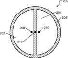
다른 특징들에서, 적어도 3 개의 전극들은 파이 형상 (pie-shaped) 이고, 시스템은 적어도 3 개의 전극들보다 더 큰 반경을 갖는 환형 전극을 더 포함한다.In other features, the at least three electrodes are pie-shaped and the system further includes an annular electrode having a larger radius than the at least three electrodes.
다른 특징들에서, 환형 전극은 방사상으로 내향으로 연장하는 복수의 스포크-유사 (spoke-like) 부분들을 포함한다. 스포크-유사 부분들 각각은 적어도 3 개의 전극들로부터 상이한 쌍의 전극들 사이에 배치된다.In other features, the annular electrode includes a plurality of spoke-like portions extending radially inward. Each of the spoke-like portions is disposed between different pairs of electrodes from at least three electrodes.
다른 특징들에서, 페데스탈 및 샤워헤드는 수직 축을 따라 배치된다. 적어도 3 개의 전극들 및 환형 전극은 수직 축에 수직인 수평 평면에 평행한 하나 이상의 평면들의 페데스탈 내에 배치된다.In other features, the pedestal and showerhead are arranged along a vertical axis. At least three electrodes and an annular electrode are arranged in the pedestal in one or more planes parallel to a horizontal plane perpendicular to the vertical axis.
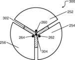
다른 특징들에서, 적어도 3 개의 전극들은 파이 형상이고 그리고 시스템은 적어도 3 개의 전극들보다 더 작은 반경을 갖는 디스크 형상 전극을 더 포함한다.In other features, the at least three electrodes are pie-shaped and the system further includes a disk-shaped electrode having a smaller radius than the at least three electrodes.
다른 특징들에서, 페데스탈 및 샤워헤드는 수직 축을 따라 배치된다. 적어도 3 개의 전극들은 수직 축에 수직인 수평 평면에 평행한 하나 이상의 평면들의 페데스탈 내에 배치된다. 디스크 형상 전극은 수평 평면에 평행한 별개의 플레이트의 페데스탈 내에 배치된다.In other features, the pedestal and showerhead are arranged along a vertical axis. At least three electrodes are disposed within the pedestal in one or more planes parallel to a horizontal plane perpendicular to the vertical axis. The disk-shaped electrode is placed within the pedestal of separate plates parallel to the horizontal plane.
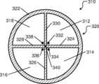
다른 특징들에서, 적어도 3 개의 전극들은 파이 형상이고 그리고 시스템은 적어도 3 개의 전극들보다 더 큰 반경을 갖고 적어도 3 개의 전극들 둘레에 배치된 복수의 원호 형상 전극들을 더 포함한다.In other features, the at least three electrodes are pie-shaped and the system further includes a plurality of arc-shaped electrodes disposed around the at least three electrodes and having a radius greater than the at least three electrodes.
또 다른 특징에서, 적어도 3 개의 전극들 및 복수의 원호 형상 전극들은 수평 평면에 평행한 하나 이상의 평면들의 페데스탈 내에 배치된다.In another feature, at least three electrodes and a plurality of arc-shaped electrodes are disposed within the pedestal in one or more planes parallel to the horizontal plane.
다른 특징들에서, 시스템은 복수의 스위치들을 더 포함하고 그리고 제어기는 복수의 스위치들을 사용하여 쌍들로 적어도 3 개의 전극들에 연결되도록 구성된다.In other features, the system further includes a plurality of switches and the controller is configured to connect at least three electrodes in pairs using the plurality of switches.
또 다른 특징에서, 제어기는 임피던스들을 센싱하기 위해 적어도 3 개의 전극들의 각각의 쌍들에 직접 연결된 복수의 센싱 회로들을 포함한다.In another feature, the controller includes a plurality of sensing circuits directly connected to each pair of at least three electrodes for sensing impedances.
다른 특징들에서, 시스템은 복수의 스위치들을 더 포함하고, 그리고 제어기는 복수의 스위치들을 사용하여 쌍들로 적어도 3 개의 전극들 및 환형 전극에 연결되도록 구성되고, 쌍들 각각은 환형 전극 및 적어도 3 개의 전극들 중 상이한 일 전극을 포함한다.In other features, the system further includes a plurality of switches, and the controller is configured to connect to the at least three electrodes and the annular electrode in pairs using the plurality of switches, each of the pairs having an annular electrode and at least three electrodes. Includes different electrodes.
다른 특징들에서, 시스템은 복수의 스위치들을 더 포함하고, 그리고 제어기는 복수의 스위치들을 사용하여 쌍들로 적어도 3 개의 전극들 및 디스크 형상 전극에 연결되도록 구성되고, 쌍들 각각은 디스크 형상 전극 및 적어도 3 개의 전극들 중 상이한 일 전극을 포함한다.In other features, the system further includes a plurality of switches, and the controller is configured to connect to the at least three electrodes and the disk-shaped electrode in pairs using the plurality of switches, each of the pairs having a disk-shaped electrode and at least three It includes one electrode that is different among the electrodes.
다른 특징들에서, 시스템은 복수의 스위치들을 더 포함하고, 그리고 제어기는 복수의 스위치들을 사용하여 쌍들로 적어도 3 개의 전극들 및 복수의 원호 형상 전극들에 연결되도록 구성되고, 쌍들 각각은 적어도 3 개의 전극들 중 상이한 일 전극 및 복수의 원호 형상 전극들 중 상이한 일 원호 형상 전극을 포함한다.In other features, the system further includes a plurality of switches, and the controller is configured to connect to at least three electrodes and a plurality of arc-shaped electrodes in pairs using the plurality of switches, each of the pairs having at least three It includes one different electrode among the electrodes and one different arc-shaped electrode among the plurality of arc-shaped electrodes.
다른 특징들에서, 페데스탈은 베이스플레이트 및 베이스플레이트 상에 배치된 유전체 플레이트를 포함한다. 적어도 3 개의 전극들은 유전체 플레이트에 배치된다.In other features, the pedestal includes a base plate and a dielectric plate disposed on the base plate. At least three electrodes are disposed on the dielectric plate.
또 다른 특징에서, 적어도 3 개의 전극들은 단일 DC 전위에 연결된다.In another feature, at least three electrodes are connected to a single DC potential.
다른 특징들에서, 적어도 3 개의 전극들은 제 1 극성을 갖는 제 1 DC 전위에 연결되고 그리고 원주형 전극은 제 1 극성과 반대인 제 2 극성을 갖는 제 2 DC 전위에 연결된다.In other features, the at least three electrodes are connected to a first DC potential with a first polarity and the columnar electrode is connected to a second DC potential with a second polarity opposite the first polarity.
다른 특징들에서, 적어도 3 개의 전극들은 제 1 극성을 갖는 제 1 DC 전위에 연결되고 그리고 디스크 형상 전극은 제 1 극성과 반대인 제 2 극성을 갖는 제 2 DC 전위에 연결된다.In other features, the at least three electrodes are connected to a first DC potential with a first polarity and the disk-shaped electrode is connected to a second DC potential with a second polarity opposite the first polarity.
다른 특징들에서, 적어도 3 개의 전극들은 제 1 극성을 갖는 제 1 DC 전위에 연결되고 그리고 복수의 원호 형상 전극들은 제 1 극성과 반대인 제 2 극성을 갖는 제 2 DC 전위에 연결된다.In other features, at least three electrodes are connected to a first DC potential having a first polarity and a plurality of arc-shaped electrodes are connected to a second DC potential having a second polarity opposite the first polarity.
다른 특징들에서, 디스크 형상 전극은 제 1 전위에 연결되고 그리고 적어도 3 개의 전극들은 (360 °/적어도 3 개의 전극들의 총 수) 의 위상 시프트를 갖는 시변 (time-varying) 전위에 연결된다.In other features, the disk-shaped electrode is connected to a first potential and at least three electrodes are connected to a time-varying potential with a phase shift of (360°/total number of at least three electrodes).
다른 특징들에서, 적어도 3 개의 전극들은 제 1 쌍의 전극들 및 제 2 쌍의 전극들을 포함한다. 제 1 쌍의 전극들은 서로 정반대로 (diametrically opposite) 배치되고 제 1 극성을 갖는 제 1 DC 전위에 연결된다. 제 2 쌍의 전극들은 서로 정반대로 배치되고 제 1 극성과 반대인 제 2 극성을 갖는 제 2 DC 전위에 연결된다.In other features, the at least three electrodes include a first pair of electrodes and a second pair of electrodes. The first pair of electrodes are arranged diametrically opposite each other and connected to a first DC potential having a first polarity. The second pair of electrodes are disposed diametrically opposite each other and are connected to a second DC potential having a second polarity opposite to the first polarity.
다른 특징들에서, 적어도 3 개의 전극들은 제 1 쌍의 전극들 및 제 2 쌍의 전극들을 포함한다. 제 1 쌍의 전극들은 서로 정반대로 배치되고 제 1 극성 및 제 1 극성과 반대인 제 2 극성을 갖는 제 1 시변 전위들에 각각 연결되는 제 1 전극 및 제 2 전극을 포함한다. 제 2 쌍의 전극들은 서로 정반대로 배치되고 제 1 극성 및 제 2 극성을 갖는 제 2 시변 전위들에 각각 연결되는 제 3 전극 및 제 4 전극을 포함한다. 제 2 시변 전위들은 (360 °/적어도 3 개의 전극들의 총 수) 의 위상 시프트를 갖는다.In other features, the at least three electrodes include a first pair of electrodes and a second pair of electrodes. The first pair of electrodes includes a first electrode and a second electrode disposed diametrically opposed to each other and connected respectively to a first polarity and to first time-varying potentials having a second polarity opposite the first polarity. The second pair of electrodes includes a third electrode and a fourth electrode arranged diametrically opposite to each other and connected respectively to second time-varying potentials having a first polarity and a second polarity. The second time-varying potentials have a phase shift of (360°/total number of at least 3 electrodes).
또 다른 특징에서, 제어기는 페데스탈과 샤워헤드 사이에 존재하는 플라즈마에 의해 적어도 3 개의 전극들과 샤워헤드 사이의 임피던스들을 센싱함으로써 페데스탈-투-샤워헤드 갭 및 페데스탈과 샤워헤드 사이의 상대적인 틸팅의 크기 및 방향 중 적어도 하나를 측정하도록 구성된다.In another feature, the controller determines the magnitude of the pedestal-to-showerhead gap and the relative tilt between the pedestal and the showerhead by sensing the impedances between the showerhead and at least three electrodes by the plasma existing between the pedestal and the showerhead. and is configured to measure at least one of a direction.
여전히 다른 특징들에서, 시스템은 페데스탈 및 제어기를 포함한다. 페데스탈은 프로세싱 챔버에서 샤워헤드 아래에 배치된다. 페데스탈은 프로세싱 동안 기판을 페데스탈에 클램핑하기 위해 적어도 3 개의 전극들을 포함한다. 적어도 3 개의 전극들은 파이 형상이다. 페데스탈은 적어도 3 개의 전극들보다 더 큰 반경을 갖는 환형 전극을 포함한다. 제어기는 샤워헤드와 적어도 3 개의 전극들 및 환형 전극 사이의 임피던스들을 센싱함으로써 페데스탈-투-샤워헤드 갭 및 페데스탈과 샤워헤드 사이의 상대적인 틸팅의 크기 및 방향 중 적어도 하나를 측정하도록 구성된다.Among still other features, the system includes a pedestal and a controller. A pedestal is placed below the showerhead in the processing chamber. The pedestal includes at least three electrodes to clamp the substrate to the pedestal during processing. At least three electrodes are pie-shaped. The pedestal includes an annular electrode having a greater radius than at least three electrodes. The controller is configured to measure at least one of the pedestal-to-showerhead gap and the magnitude and direction of relative tilting between the pedestal and the showerhead by sensing impedances between the showerhead and the at least three electrodes and the annular electrode.
다른 특징들에서, 환형 전극은 방사상으로 내향으로 연장하는 복수의 스포크-유사 부분들을 포함한다. 스포크-유사 부분들 각각은 적어도 3 개의 전극들로부터 상이한 쌍의 전극들 사이에 배치된다.In other features, the annular electrode includes a plurality of spoke-like portions extending radially inward. Each of the spoke-like portions is disposed between different pairs of electrodes from at least three electrodes.
다른 특징들에서, 페데스탈 및 샤워헤드는 수직 축을 따라 배치된다. 적어도 3 개의 전극들 및 환형 전극은 수직 축에 수직인 수평 평면에 평행한 하나 이상의 평면들의 페데스탈 내에 배치된다.In other features, the pedestal and showerhead are arranged along a vertical axis. At least three electrodes and an annular electrode are arranged in the pedestal in one or more planes parallel to a horizontal plane perpendicular to the vertical axis.
다른 특징들에서, 시스템은 복수의 스위치들을 더 포함한다. 제어기는 복수의 스위치들을 사용하여 쌍들로 적어도 3 개의 전극들 및 환형 전극에 연결되도록 구성되고, 쌍들 각각은 환형 전극 및 적어도 3 개의 전극들 중 상이한 일 전극을 포함한다.In other features, the system further includes a plurality of switches. The controller is configured to connect the at least three electrodes and the annular electrode in pairs using a plurality of switches, each of the pairs including an annular electrode and a different one of the at least three electrodes.
다른 특징들에서, 시스템은 페데스탈을 이동시키는 것 및 페데스탈과 샤워헤드 사이의 상대적인 틸팅을 재배향하는 것 중 적어도 하나를 하도록 구성된 복수의 액추에이터들을 더 포함한다. 복수의 액추에이터들 각각은 적어도 3 개의 자유도들을 갖는다.In other features, the system further includes a plurality of actuators configured to at least one of move the pedestal and reorient the relative tilt between the pedestal and the showerhead. Each of the plurality of actuators has at least three degrees of freedom.
다른 특징들에서, 복수의 액추에이터들은 페데스탈을 이동시키는 것 및 페데스탈을 이동시키고, 샤워헤드를 이동시키거나, 페데스탈과 샤워헤드의 상대적인 포지셔닝에 영향을 줌으로써 페데스탈과 샤워헤드 사이의 상대적인 틸팅을 재배향시키는 것 중 적어도 하나를 하도록 구성된다.In other features, the plurality of actuators are configured to move the pedestal and to reorient the relative tilt between the pedestal and the showerhead by moving the pedestal, moving the showerhead, or influencing the relative positioning of the pedestal and showerhead. It is configured to do at least one of the following:
또 다른 특징에서, 제어기는 페데스탈-투-샤워헤드 갭을 조정하고 상대적인 틸팅의 크기 및 방향 중 적어도 하나를 조정하기 위해 액추에이터들을 제어하도록 구성된다.In another feature, the controller is configured to control the actuators to adjust the pedestal-to-showerhead gap and to adjust at least one of the magnitude and direction of relative tilt.
또 다른 특징에서, 제어기는 기판이 부재하는지, 존재하지만 페데스탈에 클램핑되지 않았는지, 또는 존재하고 페데스탈에 클램핑되었는지 여부를 임피던스들에 기초하여 결정하도록 구성된다.In another feature, the controller is configured to determine based on the impedances whether the substrate is absent, present but not clamped to the pedestal, or present and clamped to the pedestal.
또 다른 특징에서, 제어기는 기판과 적어도 3 개의 전극들 및 환형 전극 사이의 임피던스들을 센싱함으로써 페데스탈-투-기판 갭 및 페데스탈과 기판 사이의 상대적인 틸팅의 크기 및 방향 중 적어도 하나를 측정하도록 구성된다.In another feature, the controller is configured to measure at least one of the pedestal-to-substrate gap and the magnitude and direction of relative tilting between the pedestal and the substrate by sensing impedances between the substrate and the at least three electrodes and the annular electrode.
또 다른 특징에서, 제어기는 기판과 적어도 3 개의 전극들 및 환형 전극 사이의 임피던스들을 센싱함으로써 페데스탈-투-기판 상대적인 편심을 측정하도록 구성된다.In another feature, the controller is configured to measure pedestal-to-substrate relative eccentricity by sensing impedances between the substrate and at least three electrodes and an annular electrode.
또 다른 특징에서, 제어기는 임피던스들을 센싱하기 위해 환형 전극과 적어도 3 개의 전극들의 각각의 쌍들에 직접 연결된 복수의 센싱 회로들을 포함한다.In another feature, the controller includes a plurality of sensing circuits directly connected to each pair of the annular electrode and at least three electrodes for sensing impedances.
다른 특징들에서, 페데스탈은 베이스플레이트 및 베이스플레이트 상에 배치된 유전체 플레이트를 포함한다. 적어도 3 개의 전극들 및 환형 전극은 유전체 플레이트 내에 배치된다.In other features, the pedestal includes a base plate and a dielectric plate disposed on the base plate. At least three electrodes and an annular electrode are disposed within the dielectric plate.
또 다른 특징에서, 적어도 3 개의 전극들 및 환형 전극은 단일 DC 전위에 연결된다.In another feature, at least three electrodes and the annular electrode are connected to a single DC potential.
또 다른 특징에서, 적어도 3 개의 전극들은 제 1 극성을 갖는 제 1 DC 전위에 연결되고 그리고 환형 전극은 제 1 극성과 반대인 제 2 극성을 갖는 제 2 DC 전위에 연결된다.In another feature, the at least three electrodes are connected to a first DC potential with a first polarity and the annular electrode is connected to a second DC potential with a second polarity opposite the first polarity.
또 다른 특징에서, 적어도 3 개의 전극들은 제 1 쌍의 전극들 및 제 2 쌍의 전극들을 포함한다. 제 1 쌍의 전극들은 서로 정반대로 배치되고 제 1 극성을 갖는 제 1 DC 전위에 연결된다. 제 2 쌍의 전극들은 서로 정반대로 배치되고 제 1 극성과 반대인 제 2 극성을 갖는 제 2 DC 전위에 연결된다.In another feature, the at least three electrodes include a first pair of electrodes and a second pair of electrodes. The first pair of electrodes are arranged diametrically opposite to each other and are connected to a first DC potential with a first polarity. The second pair of electrodes are disposed diametrically opposite each other and are connected to a second DC potential having a second polarity opposite to the first polarity.
또 다른 특징에서, 적어도 3 개의 전극들은 제 1 쌍의 전극들 및 제 2 쌍의 전극들을 포함한다. 제 1 쌍의 전극들은 서로 정반대로 배치되고 제 1 극성 및 제 1 극성과 반대인 제 2 극성을 갖는 제 1 시변 전위들에 각각 연결되는 제 1 전극 및 제 2 전극을 포함한다. 제 2 쌍의 전극들은 서로 정반대로 배치되고 제 1 극성 및 제 2 극성을 갖는 제 2 시변 전위들에 각각 연결되는 제 3 전극 및 제 4 전극을 포함한다. 제 2 시변 전위들은 (360 °/적어도 3 개의 전극들의 총 수) 의 위상 시프트를 갖는다.In another feature, the at least three electrodes include a first pair of electrodes and a second pair of electrodes. The first pair of electrodes includes a first electrode and a second electrode disposed diametrically opposed to each other and connected respectively to a first polarity and to first time-varying potentials having a second polarity opposite the first polarity. The second pair of electrodes includes a third electrode and a fourth electrode arranged diametrically opposite to each other and connected respectively to second time-varying potentials having a first polarity and a second polarity. The second time-varying potentials have a phase shift of (360°/total number of at least 3 electrodes).
또 다른 특징에서, 제어기는 페데스탈과 샤워헤드 사이에 존재하는 플라즈마에 의해 샤워헤드와 적어도 3 개의 전극들 및 환형 전극 사이의 임피던스들을 센싱함으로써 페데스탈-투-샤워헤드 갭 및 페데스탈과 샤워헤드 사이의 상대적인 틸팅의 크기 및 방향 중 적어도 하나를 측정하도록 구성된다.In another feature, the controller determines the pedestal-to-showerhead gap and the relative pedestal-to-showerhead gap by sensing impedances between the showerhead and at least three electrodes and an annular electrode by plasma existing between the pedestal and the showerhead. It is configured to measure at least one of the magnitude and direction of tilting.
여전히 다른 특징들에서, 시스템은 페데스탈 및 제어기를 포함한다. 페데스탈은 프로세싱 챔버에서 샤워헤드 아래에 배치된다. 페데스탈은 프로세싱 동안 기판을 페데스탈에 클램핑하기 위해 적어도 3 개의 전극들을 포함한다. 적어도 3 개의 전극들은 파이 형상이다. 페데스탈은 적어도 3 개의 전극들보다 더 작은 반경을 갖는 디스크 형상 전극을 포함한다. 제어기는 샤워헤드와 적어도 3 개의 전극들 및 디스크 형상 전극 사이의 임피던스들을 센싱함으로써 페데스탈-투-샤워헤드 갭 및 페데스탈과 샤워헤드 사이의 상대적인 틸팅의 크기 및 방향 중 적어도 하나를 측정하도록 구성된다.Among still other features, the system includes a pedestal and a controller. A pedestal is placed below the showerhead in the processing chamber. The pedestal includes at least three electrodes to clamp the substrate to the pedestal during processing. At least three electrodes are pie-shaped. The pedestal includes a disk-shaped electrode with a smaller radius than at least three electrodes. The controller is configured to measure at least one of the pedestal-to-showerhead gap and the magnitude and direction of relative tilting between the pedestal and the showerhead by sensing impedances between the showerhead and the at least three electrodes and the disk-shaped electrode.
다른 특징들에서, 페데스탈 및 샤워헤드는 수직 축을 따라 배치된다. 적어도 3 개의 전극들은 수직 축에 수직인 수평 평면에 평행한 하나 이상의 평면들의 페데스탈 내에 배치되고 그리고 디스크 형상 전극은 수평 평면에 평행한 별개의 플레이트의 페데스탈 내에 배치된다.In other features, the pedestal and showerhead are arranged along a vertical axis. At least three electrodes are disposed in a pedestal of one or more planes parallel to a horizontal plane perpendicular to the vertical axis and a disk-shaped electrode is disposed in a pedestal of separate plates parallel to the horizontal plane.
다른 특징들에서, 시스템은 복수의 스위치들을 더 포함한다. 제어기는 복수의 스위치들을 사용하여 쌍들로 적어도 3 개의 전극들 및 디스크 형상 전극에 연결되도록 구성되고, 쌍들 각각은 디스크 형상 전극 및 적어도 3 개의 전극들 중 상이한 일 전극을 포함한다.In other features, the system further includes a plurality of switches. The controller is configured to connect the at least three electrodes and the disk-shaped electrode in pairs using a plurality of switches, each of the pairs including a disk-shaped electrode and a different one of the at least three electrodes.
다른 특징들에서, 적어도 3 개의 전극들은 제 1 극성을 갖는 제 1 DC 전위에 연결된다. 디스크 형상 전극은 제 1 극성과 반대인 제 2 극성을 갖는 제 2 DC 전위에 연결된다.In other features, at least three electrodes are connected to a first DC potential with a first polarity. The disk-shaped electrode is connected to a second DC potential having a second polarity opposite to the first polarity.
다른 특징들에서, 시스템은 페데스탈을 이동시키는 것 및 페데스탈과 샤워헤드 사이의 상대적인 틸팅을 재배향하는 것 중 적어도 하나를 하도록 구성된 복수의 액추에이터들을 더 포함한다. 복수의 액추에이터들 각각은 적어도 3 개의 자유도들을 갖는다.In other features, the system further includes a plurality of actuators configured to at least one of move the pedestal and reorient the relative tilt between the pedestal and the showerhead. Each of the plurality of actuators has at least three degrees of freedom.
다른 특징들에서, 복수의 액추에이터들은 페데스탈을 이동시키는 것 및 페데스탈을 이동시키고, 샤워헤드를 이동시키거나, 페데스탈과 샤워헤드의 상대적인 포지셔닝에 영향을 줌으로써 페데스탈과 샤워헤드 사이의 상대적인 틸팅을 재배향시키는 것 중 적어도 하나를 하도록 구성된다.In other features, the plurality of actuators are configured to move the pedestal and to reorient the relative tilt between the pedestal and the showerhead by moving the pedestal, moving the showerhead, or influencing the relative positioning of the pedestal and showerhead. It is configured to do at least one of the following:
또 다른 특징에서, 제어기는 페데스탈-투-샤워헤드 갭을 조정하고 상대적인 틸팅의 크기 및 방향 중 적어도 하나를 조정하기 위해 액추에이터들을 제어하도록 구성된다.In another feature, the controller is configured to control the actuators to adjust the pedestal-to-showerhead gap and to adjust at least one of the magnitude and direction of relative tilt.
또 다른 특징에서, 제어기는 기판이 부재하는지, 존재하지만 페데스탈에 클램핑되지 않았는지, 또는 존재하고 페데스탈에 클램핑되었는지 여부를 임피던스들에 기초하여 결정하도록 구성된다.In another feature, the controller is configured to determine based on the impedances whether the substrate is absent, present but not clamped to the pedestal, or present and clamped to the pedestal.
또 다른 특징에서, 제어기는 기판과 적어도 3 개의 전극들 및 디스크 형상 전극 사이의 임피던스들을 센싱함으로써 페데스탈-투-기판 갭 및 페데스탈과 기판 사이의 상대적인 틸팅의 크기 및 방향 중 적어도 하나를 측정하도록 구성된다.In another feature, the controller is configured to measure at least one of the pedestal-to-substrate gap and the magnitude and direction of relative tilting between the pedestal and the substrate by sensing impedances between the substrate and the at least three electrodes and the disk-shaped electrode. .
또 다른 특징에서, 제어기는 기판과 적어도 3 개의 전극들 및 디스크 형상 전극 사이의 임피던스들을 센싱함으로써 페데스탈-투-기판 상대적인 편심을 측정하도록 구성된다.In another feature, the controller is configured to measure pedestal-to-substrate relative eccentricity by sensing impedances between the substrate and at least three electrodes and a disk-shaped electrode.
또 다른 특징에서, 제어기는 임피던스들을 센싱하기 위해 디스크 형상 전극과 적어도 3 개의 전극들의 각각의 쌍들에 직접 연결된 복수의 센싱 회로들을 포함한다.In another feature, the controller includes a disc-shaped electrode and a plurality of sensing circuits directly connected to each pair of at least three electrodes for sensing impedances.
다른 특징들에서, 페데스탈은 베이스플레이트 및 베이스플레이트 상에 배치된 유전체 플레이트를 포함한다. 적어도 3 개의 전극들 및 디스크 형상 전극은 유전체 플레이트 내에 배치된다.In other features, the pedestal includes a base plate and a dielectric plate disposed on the base plate. At least three electrodes and a disk-shaped electrode are disposed within the dielectric plate.
또 다른 특징에서, 적어도 3 개의 전극들 및 디스크 형상 전극은 단일 DC 전위에 연결된다.In another feature, at least three electrodes and a disk-shaped electrode are connected to a single DC potential.
또 다른 특징에서, 적어도 3 개의 전극들은 제 1 쌍의 전극들 및 제 2 쌍의 전극들을 포함한다. 제 1 쌍의 전극들은 서로 정반대로 배치되고 제 1 극성을 갖는 제 1 DC 전위에 연결된다. 제 2 쌍의 전극들은 서로 정반대로 배치되고 제 1 극성과 반대인 제 2 극성을 갖는 제 2 DC 전위에 연결된다.In another feature, the at least three electrodes include a first pair of electrodes and a second pair of electrodes. The first pair of electrodes are arranged diametrically opposite to each other and are connected to a first DC potential with a first polarity. The second pair of electrodes are disposed diametrically opposite each other and are connected to a second DC potential having a second polarity opposite to the first polarity.
또 다른 특징에서, 적어도 3 개의 전극들은 제 1 쌍의 전극들 및 제 2 쌍의 전극들을 포함한다. 제 1 쌍의 전극들은 서로 정반대로 배치되고 제 1 극성 및 제 1 극성과 반대인 제 2 극성을 갖는 제 1 시변 전위들에 각각 연결되는 제 1 전극 및 제 2 전극을 포함한다. 제 2 쌍의 전극들은 서로 정반대로 배치되고 제 1 극성 및 제 2 극성을 갖는 제 2 시변 전위들에 각각 연결되는 제 3 전극 및 제 4 전극을 포함한다. 제 2 시변 전위들은 (360 °/적어도 3 개의 전극들의 총 수) 의 위상 시프트를 갖는다.In another feature, the at least three electrodes include a first pair of electrodes and a second pair of electrodes. The first pair of electrodes includes a first electrode and a second electrode disposed diametrically opposed to each other and connected respectively to a first polarity and to first time-varying potentials having a second polarity opposite the first polarity. The second pair of electrodes includes a third electrode and a fourth electrode arranged diametrically opposite to each other and connected respectively to second time-varying potentials having a first polarity and a second polarity. The second time-varying potentials have a phase shift of (360°/total number of at least 3 electrodes).
또 다른 특징에서, 제어기는 페데스탈과 샤워헤드 사이에 존재하는 플라즈마에 의해 샤워헤드와 적어도 3 개의 전극들 및 디스크 형상 전극 사이의 임피던스들을 센싱함으로써 페데스탈-투-샤워헤드 갭 및 페데스탈과 샤워헤드 사이의 상대적인 틸팅의 크기 및 방향 중 적어도 하나를 측정하도록 구성된다.In another feature, the controller determines the pedestal-to-showerhead gap and the pedestal-to-showerhead gap by sensing impedances between the showerhead and at least three electrodes and a disk-shaped electrode by plasma existing between the pedestal and the showerhead. It is configured to measure at least one of the magnitude and direction of relative tilting.
여전히 다른 특징들에서, 시스템은 페데스탈 및 제어기를 포함한다. 페데스탈은 프로세싱 챔버에서 샤워헤드 아래에 배치된다. 페데스탈은 프로세싱 동안 기판을 페데스탈에 클램핑하기 위해 적어도 3 개의 전극들을 포함한다. 적어도 3 개의 전극들은 파이 형상이다. 페데스탈은 적어도 3 개의 전극들보다 더 큰 반경을 갖고 적어도 3 개의 전극들 둘레에 배치된 복수의 원호 형상 전극들을 포함한다. 제어기는 샤워헤드와 적어도 3 개의 전극들 및 복수의 원호 형상 전극들 사이의 임피던스들을 센싱함으로써 페데스탈-투-샤워헤드 갭 및 페데스탈과 샤워헤드 사이의 상대적인 틸팅의 크기 및 방향 중 적어도 하나를 측정하도록 구성된다.Among still other features, the system includes a pedestal and a controller. A pedestal is placed below the showerhead in the processing chamber. The pedestal includes at least three electrodes to clamp the substrate to the pedestal during processing. At least three electrodes are pie-shaped. The pedestal includes a plurality of arc-shaped electrodes disposed around the at least three electrodes and having a radius greater than the at least three electrodes. The controller is configured to measure at least one of the pedestal-to-showerhead gap and the magnitude and direction of relative tilting between the pedestal and the showerhead by sensing impedances between the showerhead and at least three electrodes and a plurality of arc-shaped electrodes. do.
다른 특징들에서, 페데스탈 및 샤워헤드는 수직 축을 따라 배치된다. 적어도 3 개의 전극들 및 복수의 원호 형상 전극들은 수직 축에 수직인 수평 평면에 평행한 하나 이상의 평면들의 페데스탈 내에 배치된다.In other features, the pedestal and showerhead are arranged along a vertical axis. At least three electrodes and a plurality of arc-shaped electrodes are arranged in a pedestal in one or more planes parallel to a horizontal plane perpendicular to the vertical axis.
다른 특징들에서, 시스템은 복수의 스위치들을 더 포함한다. 제어기는 복수의 스위치들을 사용하여 쌍들로 적어도 3 개의 전극들 및 복수의 원호 형상 전극들에 연결되도록 구성되고, 쌍들 각각은 적어도 3 개의 전극들 중 상이한 일 전극 및 복수의 원호 형상 전극들 중 상이한 일 원호 형상 전극을 포함한다.In other features, the system further includes a plurality of switches. The controller is configured to connect the at least three electrodes and the plurality of arc-shaped electrodes in pairs using a plurality of switches, each of the pairs being connected to a different one of the at least three electrodes and a different one of the plurality of arc-shaped electrodes. It includes an arc-shaped electrode.
다른 특징들에서, 적어도 3 개의 전극들은 제 1 극성을 갖는 제 1 DC 전위에 연결된다. 복수의 원호 형상 전극들은 제 1 극성과 반대인 제 2 극성을 갖는 제 2 DC 전위에 연결된다.In other features, at least three electrodes are connected to a first DC potential with a first polarity. The plurality of arc-shaped electrodes are connected to a second DC potential having a second polarity opposite to the first polarity.
다른 특징들에서, 시스템은 페데스탈을 이동시키는 것 및 페데스탈과 샤워헤드 사이의 상대적인 틸팅을 재배향하는 것 중 적어도 하나를 하도록 구성된 복수의 액추에이터들을 더 포함한다. 복수의 액추에이터들 각각은 적어도 3 개의 자유도들을 갖는다.In other features, the system further includes a plurality of actuators configured to at least one of move the pedestal and reorient the relative tilt between the pedestal and the showerhead. Each of the plurality of actuators has at least three degrees of freedom.
다른 특징들에서, 복수의 액추에이터들은 페데스탈을 이동시키는 것 및 페데스탈을 이동시키고, 샤워헤드를 이동시키거나, 페데스탈과 샤워헤드의 상대적인 포지셔닝에 영향을 줌으로써 페데스탈과 샤워헤드 사이의 상대적인 틸팅을 재배향시키는 것 중 적어도 하나를 하도록 구성된다.In other features, the plurality of actuators are configured to move the pedestal and to reorient the relative tilt between the pedestal and the showerhead by moving the pedestal, moving the showerhead, or influencing the relative positioning of the pedestal and showerhead. It is configured to do at least one of the following:
또 다른 특징에서, 제어기는 페데스탈-투-샤워헤드 갭을 조정하고 상대적인 틸팅의 크기 및 방향 중 적어도 하나를 조정하기 위해 액추에이터들을 제어하도록 구성된다.In another feature, the controller is configured to control the actuators to adjust the pedestal-to-showerhead gap and to adjust at least one of the magnitude and direction of relative tilt.
또 다른 특징에서, 제어기는 기판이 부재하는지, 존재하지만 페데스탈에 클램핑되지 않았는지, 또는 존재하고 페데스탈에 클램핑되었는지 여부를 임피던스들에 기초하여 결정하도록 구성된다.In another feature, the controller is configured to determine based on the impedances whether the substrate is absent, present but not clamped to the pedestal, or present and clamped to the pedestal.
또 다른 특징에서, 제어기는 기판과 적어도 3 개의 전극들 및 복수의 원호 형상 전극들 사이의 임피던스들을 센싱함으로써 페데스탈-투-기판 갭 및 페데스탈과 기판 사이의 상대적인 틸팅의 크기 및 방향 중 적어도 하나를 측정하도록 구성된다.In another feature, the controller measures at least one of the pedestal-to-substrate gap and the magnitude and direction of the relative tilting between the pedestal and the substrate by sensing impedances between the substrate and at least three electrodes and a plurality of arc-shaped electrodes. It is configured to do so.
또 다른 특징에서, 제어기는 기판과 적어도 3 개의 전극들 및 복수의 원호 형상 전극들 사이의 임피던스들을 센싱함으로써 페데스탈-투-기판 상대적인 편심을 측정하도록 구성된다.In another feature, the controller is configured to measure pedestal-to-substrate relative eccentricity by sensing impedances between the substrate and at least three electrodes and a plurality of arc-shaped electrodes.
또 다른 특징에서, 제어기는 임피던스들을 센싱하기 위해 복수의 원호 형상 전극들과 적어도 3 개의 전극들의 각각의 쌍들에 직접 연결된 복수의 센싱 회로들을 포함한다.In another feature, the controller includes a plurality of arc-shaped electrodes for sensing impedances and a plurality of sensing circuits directly connected to each pair of at least three electrodes.
또 다른 특징에서, 페데스탈은 베이스플레이트 및 베이스플레이트 상에 배치된 유전체 플레이트를 포함한다. 적어도 3 개의 전극들 및 복수의 원호 형상 전극들은 유전체 플레이트 내에 배치된다.In another feature, the pedestal includes a base plate and a dielectric plate disposed on the base plate. At least three electrodes and a plurality of arc-shaped electrodes are disposed within the dielectric plate.
또 다른 특징에서, 적어도 3 개의 전극들 및 복수의 원호 형상 전극들은 단일 DC 전위에 연결된다.In another feature, at least three electrodes and a plurality of arc-shaped electrodes are connected to a single DC potential.
다른 특징들에서, 적어도 3 개의 전극들은 제 1 쌍의 전극들 및 제 2 쌍의 전극들을 포함한다. 제 1 쌍의 전극들은 서로 정반대로 배치되고 제 1 극성을 갖는 제 1 DC 전위에 연결된다. 제 2 쌍의 전극들은 서로 정반대로 배치되고 제 1 극성과 반대인 제 2 극성을 갖는 제 2 DC 전위에 연결된다.In other features, the at least three electrodes include a first pair of electrodes and a second pair of electrodes. The first pair of electrodes are arranged diametrically opposite to each other and are connected to a first DC potential with a first polarity. The second pair of electrodes are placed diametrically opposite each other and connected to a second DC potential having a second polarity opposite to the first polarity.
다른 특징들에서, 적어도 3 개의 전극들은 제 1 쌍의 전극들 및 제 2 쌍의 전극들을 포함한다. 제 1 쌍의 전극들은 서로 정반대로 배치되고 제 1 극성 및 제 1 극성과 반대인 제 2 극성을 갖는 제 1 시변 전위들에 각각 연결되는 제 1 전극 및 제 2 전극을 포함한다. 제 2 쌍의 전극들은 서로 정반대로 배치되고 제 1 극성 및 제 2 극성을 갖는 제 2 시변 전위들에 각각 연결되는 제 3 전극 및 제 4 전극을 포함한다. 제 2 시변 전위들은 (360 °/적어도 3 개의 전극들의 총 수) 의 위상 시프트를 갖는다.In other features, the at least three electrodes include a first pair of electrodes and a second pair of electrodes. The first pair of electrodes includes a first electrode and a second electrode disposed diametrically opposed to each other and connected respectively to a first polarity and to first time-varying potentials having a second polarity opposite the first polarity. The second pair of electrodes includes a third electrode and a fourth electrode arranged diametrically opposite to each other and connected respectively to second time-varying potentials having a first polarity and a second polarity. The second time-varying potentials have a phase shift of (360°/total number of at least 3 electrodes).
또 다른 특징에서, 제어기는 페데스탈과 샤워헤드 사이에 존재하는 플라즈마에 의해 샤워헤드와 적어도 3 개의 전극들 및 복수의 원호 형상 전극들 사이의 임피던스들을 센싱함으로써 페데스탈-투-샤워헤드 갭 및 페데스탈과 샤워헤드 사이의 상대적인 틸팅의 크기 및 방향 중 적어도 하나를 측정하도록 구성된다.In another feature, the controller controls the pedestal-to-showerhead gap and the pedestal-to-shower gap by sensing impedances between the showerhead and at least three electrodes and a plurality of arc-shaped electrodes by plasma existing between the pedestal and the showerhead. and configured to measure at least one of the magnitude and direction of relative tilting between the heads.
본 개시의 추가 적용 가능의 영역들은 상세한 기술 (description), 청구항들 및 도면들로부터 자명해질 것이다. 상세한 기술 및 구체적인 예들은 단지 예시의 목적들을 위해 의도되고, 본 개시의 범위를 제한하도록 의도되지 않는다.Additional areas of applicability of the present disclosure will become apparent from the detailed description, claims and drawings. The detailed description and specific examples are intended for illustrative purposes only and are not intended to limit the scope of the disclosure.
본 개시는 상세한 기술 및 첨부된 도면들로부터 더 완전히 이해될 것이다.
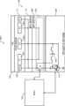
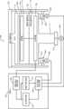
도 1은 정전 척 (electrostatic chuck; ESC) 및 샤워헤드를 포함하는 프로세싱 챔버를 포함하는 기판 프로세싱 시스템의 일 예를 도시한다.
도 2a 내지 도 2f는 ESC와 샤워헤드 사이의 갭 및 상대적인 틸팅을 측정하도록 ESC에서 사용될 수 있는 전극들의 다양한 배열들을 도시한다.
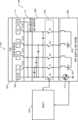
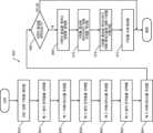
도 3a는 제어 회로들에 대한 ESC 내의 전극들 및 다른 전기적 엘리먼트들의 연결들을 구현하는 일 예를 도시한다.
도 3b 및 도 3c는 ESC 내의 3 개의 클램핑 전극들 및 무선 주파수 (radio frequency; RF) 전극을 바이어싱하기 위한 바이어싱 시스템의 일 예를 도시한다.
도 3d는 ESC 내의 4 개의 클램핑 전극들 및 RF 전극을 바이어싱하기 위한 바이어싱 시스템의 일 예를 도시한다.
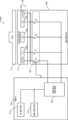
도 4a 내지 도 4d는 ESC 내의 전극들의 상이한 배열들을 활용함으로써 기판 상태들을 센싱하는 센싱 시스템들의 예들을 도시한다.
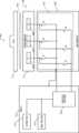
도 5a 내지 도 5d는 ESC와 샤워헤드 사이의 갭 및 상대적인 틸팅을 측정하기 위한 도 4a 내지 도 4d의 센싱 시스템들을 활용하는 시스템들의 예들을 도시한다.
도 6a 및 도 6b는 ESC와 샤워헤드 사이의 갭 및 상대적인 틸팅을 조정하기 위해 사용된 메커니즘들의 예들을 도시한다.
도 7은 ESC와 샤워헤드 사이의 갭 및 상대적인 틸팅을 측정하고 조정하기 위한 방법을 도시한다.
도 8a는 기판이 ESC 상에서 잘못 배치되었는지 (즉, 중심을 벗어나 배치되었는지) 검출하기 위한 방법을 도시한다.
도 8b는 프로세싱 동안 기판이 ESC 상에서 중심을 벗어나 이동하는지 여부를 검출하기 위한 방법을 도시한다.
도 9는 ESC와 기판 사이의 갭 및 상대적인 틸팅을 측정하기 위한 방법을 도시한다.
도 10은 ESC와 함께 사용된 리프트 핀들의 일 예를 도시한다.
도 11a 및 도 11b는 도 3b 내지 도 3d에 도시된 바이어싱 시스템들을 사용하여 채용된 클램핑 스킴들의 예들에서 도 2b 내지 도 2f에 도시된 전극들에 인가된 전위들의 타이밍도들 (timing diagrams) 이다.
도면들에서, 참조 번호들은 유사한 그리고/또는 동일한 엘리먼트들을 식별하기 위해 재사용될 수도 있다.The present disclosure will be more fully understood from the detailed description and accompanying drawings.
1 shows an example of a substrate processing system including a processing chamber including an electrostatic chuck (ESC) and a showerhead.
2A-2F show various arrangements of electrodes that can be used in an ESC to measure the relative tilt and gap between the ESC and the showerhead.
Figure 3a shows an example of implementing connections of electrodes and other electrical elements in the ESC to control circuits.
3B and 3C show an example of a biasing system for biasing three clamping electrodes and a radio frequency (RF) electrode in an ESC.
Figure 3d shows an example of a biasing system for biasing the RF electrode and four clamping electrodes in the ESC.
4A-4D show examples of sensing systems that sense substrate conditions by utilizing different arrangements of electrodes within the ESC.
Figures 5A-5D show examples of systems utilizing the sensing systems of Figures 4A-4D to measure the gap and relative tilt between an ESC and a showerhead.
6A and 6B show examples of mechanisms used to adjust the gap and relative tilt between the ESC and the showerhead.
Figure 7 shows a method for measuring and adjusting the gap and relative tilt between the ESC and showerhead.
Figure 8A shows a method for detecting if a substrate is misplaced (i.e., positioned off-center) on an ESC.
Figure 8B shows a method for detecting whether a substrate moves off-center on the ESC during processing.
Figure 9 shows a method for measuring the gap and relative tilt between an ESC and a substrate.
Figure 10 shows an example of lift pins used with an ESC.
FIGS. 11A and 11B are timing diagrams of potentials applied to the electrodes shown in FIGS. 2B to 2F in examples of clamping schemes employed using the biasing systems shown in FIGS. 3B to 3D. .
In the drawings, reference numbers may be reused to identify similar and/or identical elements.
프로세스 모듈들에서, 페데스탈-투-샤워헤드 갭 (pedestal-to-showerhead gap) 및 틸팅 제어는 현대 반도체 웨이퍼 프로세싱에 중요하다. 특히, 상대적으로 고온들 (> 400 ℃) 에서 수행된 프로세스들은 다른 프로세스들보다 갭 및 틸팅 제어에 더 민감한 경향이 있고, 더 많은 프로세스들이 고온 공간으로 이동하고 있다. 페데스탈-투-샤워헤드 갭 및 틸팅은 실온에서 측정될 수 있지만, 고온 프로세스들의 측정들은 실제 프로세스 온도들로 가열될 때 프로세스 모듈의 주요 컴포넌트들이 팽창하고 이동하기 때문에 어려울 수 있다. 이러한 환경들에서 측정 시스템들은 통상적으로 간접적이고 종종 갭 및 틸팅 튜닝을 수행하기 위해 실제 기판들의 사용을 필요로 한다. 실제 기판들을 사용하는 것은 고객의 실리콘을 소비하고 기판들을 낭비한다. 따라서 이들 고온들 (> 400 ℃) 에서 동작할 수 있는 인 시츄 (in-situ) 직접 측정 시스템들이 바람직하다. 또한, 증착은 전통적인 광학 센서 윈도우들 상에 축적되어, 시간이 흐름에 따라 이러한 측정들에 사용할 수 없게 한다. 또한, 페데스탈과 샤워헤드 사이에 가시선 (line-of-sight) 센서를 구현하는 것은 프로세스 성능 문제들을 생성할 수 있다 (즉, 샤워헤드에 홀들을 부가하는 것은 균일성에 영향을 줌). 본 개시에 따라, 정전 척들 (electrostatic chucks; ESCs) 내의 전극들은 이하에 기술된 바와 같이 갭 및 틸팅을 측정하도록 채용될 수 있다.In process modules, pedestal-to-showerhead gap and tilt control are important for modern semiconductor wafer processing. In particular, processes performed at relatively high temperatures (>400°C) tend to be more sensitive to gap and tilting control than other processes, and more processes are moving into higher temperature spaces. Although pedestal-to-showerhead gap and tilt can be measured at room temperature, measurements in high temperature processes can be difficult because key components of the process module expand and move when heated to actual process temperatures. Measurement systems in these environments are typically indirect and often require the use of actual boards to perform gap and tilt tuning. Using actual boards consumes the customer's silicon and wastes the boards. Therefore, in-situ direct measurement systems that can operate at these high temperatures (>400 °C) are desirable. Additionally, deposition can build up on traditional optical sensor windows, rendering them unusable for such measurements over time. Additionally, implementing a line-of-sight sensor between the pedestal and the showerhead can create process performance issues (i.e., adding holes to the showerhead affects uniformity). In accordance with the present disclosure, electrodes in electrostatic chucks (ESCs) can be employed to measure gap and tilting as described below.
ESC들은 통상적으로 반대 극성의 양극성 (bipolar) 쌍의 내측 전극들 및 독립적으로 무선 주파수 (radio frequency; RF) 바이어싱되거나 DC 바이어싱될 수 있는 외측 전극을 포함한다. 센싱 회로는 기판 상태들: 웨이퍼 없음, 웨이퍼 존재함, 및 웨이퍼 클램핑됨을 평가하기 위해 한 쌍의 내측 전극들 사이의 임피던스를 측정할 수 있다. 본 개시는 기판을 위해 사용되는 ESC 내의 3 극성 (tripolar) 전극 배열 및 틸팅 계산들을 인에이블하는 (enable) 공간 분해능을 갖는, ESC-투-샤워헤드 갭 센싱 (ESC-to-showerhead gap sensing) 을 포함하는 시스템을 제공한다. 간략하게, 시스템은 2 개의 엘리먼트들: a) ESC를 샤워헤드의 대략 1 ㎜ (1 millimeter) 내로 이동시키고 기판 상태들을 센싱하도록 사용되는 센싱 회로를 활용함으로써 ESC-투-샤워헤드 갭을 측정하기 위한 메커니즘; 및 b) ESC-투-샤워헤드 상대적인 틸팅의 측정 및 조정을 인에이블하기 위한 부가적인 제 3 내측 전극을 포함한다.ESCs typically include a bipolar pair of opposite polarity inner electrodes and an outer electrode that can be independently radio frequency (RF) biased or DC biased. The sensing circuit may measure the impedance between a pair of inner electrodes to assess substrate conditions: wafer absent, wafer present, and wafer clamped. The present disclosure provides ESC-to-showerhead gap sensing, with spatial resolution that enables tripolar electrode arrays and tilting calculations within the ESC used for the substrate. Provides a system that includes Briefly, the system has two elements: a) to measure the ESC-to-showerhead gap by moving the ESC to within approximately 1 millimeter of the showerhead and utilizing a sensing circuitry used to sense substrate conditions; mechanism; and b) an additional third inner electrode to enable measurement and adjustment of the ESC-to-showerhead relative tilt.
a) 의 측정으로부터, 페데스탈 Z-구동 어셈블리 (즉, 샤워헤드에 대해 수직으로 페데스탈을 이동시키기 위해 전극 평면에 직교하는 구동 축을 갖는 구동 어셈블리) 로부터의 정밀 포지션 (precision position) 정보가 순 ESC-투-샤워헤드 거리 (즉, ESC-투-샤워헤드 갭) 를 계산하기 위해 ESC의 측정된 변위에 부가될 수 있다. 3 개의 전극들을 A, B, 및 C로 표기하면, 제 3 전극은 센싱 회로를 사용하여 차동 임피던스 측정들의 다음의 모드들을 허용한다: 1) A 대 B, B 대 C, 그리고 C 대 A; 및 2) 이하에 상세히 기술된 바와 같이, A 대 외측 전극, B 대 외측 전극, 및 C 대 외측 전극. 이들 측정들로부터, 샤워헤드에 대한 ESC의 국부적인 변위가 추론될 수 있다. 국부적인 변위 측정들의 3 개의 세트들로부터, 상대적인 틸팅이 계산될 수 있다. 이어서 틸팅 측정은 기판 상 성능을 튜닝하기 위해 ESC-투-샤워헤드 상대적인 틸팅을 조정하도록 사용될 수 있다. 본 개시의 이들 및 다른 특징들은 이하에 상세히 기술된다.a) From the measurements, precision position information from the pedestal Z-drive assembly (i.e. a drive assembly with a drive axis orthogonal to the electrode plane to move the pedestal perpendicular to the showerhead) -Can be added to the measured displacement of the ESC to calculate the showerhead distance (i.e. ESC-to-showerhead gap). Labeling the three electrodes A, B, and C, the third electrode allows the following modes of differential impedance measurements using the sensing circuit: 1) A to B, B to C, and C to A; and 2) A to outer electrode, B to outer electrode, and C to outer electrode, as described in detail below. From these measurements, the local displacement of the ESC relative to the showerhead can be deduced. From the three sets of local displacement measurements, the relative tilt can be calculated. The tilt measurements can then be used to adjust the ESC-to-showerhead relative tilt to tune on-board performance. These and other features of the present disclosure are described in detail below.
본 개시는 다음과 같이 구체화된다. 처음에, 본 개시의 갭 및 틸팅 측정 시스템이 구현될 수 있는 기판 프로세싱 시스템의 일 예가 도 1을 참조하여 도시되고 기술된다. 후속하여, 갭 및 틸팅 측정 시스템에서 활용될 수 있는 전극들의 다양한 배열들이 도 2a 내지 도 2f를 참조하여 도시되고 기술된다. 제어 회로들에 대한 ESC 내의 전극들 및 다른 전기적 엘리먼트들의 연결들을 구현하는 일 예가 도 3a를 참조하여 도시되고 기술된다. ESC 내의 3 개의 클램핑 전극들 및 RF 전극을 바이어싱하기 위한 바이어싱 시스템의 예들이 도 3b 및 도 3c를 참조하여 도시되고 기술된다. ESC 내의 4 개의 클램핑 전극들 및 RF 전극을 바이어싱하기 위한 바이어싱 시스템의 일 예가 도 3d를 참조하여 도시되고 기술된다. ESC 내의 전극들의 상이한 배열들을 활용함으로써 기판 상태들을 센싱하는 센싱 시스템들의 예들이 도 4a 내지 도 4d를 참조하여 도시되고 기술된다. ESC와 샤워헤드 사이의 갭 및 상대적인 틸팅을 측정하기 위한 이들 센싱 시스템들을 활용하는 시스템들의 예들이 도 5a 내지 도 5d를 참조하여 도시되고 기술된다. ESC와 샤워헤드 사이의 갭 및 상대적인 틸팅을 조정하기 위해 사용될 수 있는 메커니즘들의 예들이 도 6a 및 도 6b를 참조하여 도시되고 기술된다. ESC와 샤워헤드 사이의 갭 및 상대적인 틸팅을 측정하고 조정하기 위한 방법이 도 7을 참조하여 도시되고 기술된다. 기판이 ESC 상에서 잘못 배치되었는지 (즉, 중심을 벗어나 배치되었는지) 검출하기 위한 방법이 도 8a를 참조하여 도시되고 기술된다. 프로세싱 동안 기판이 ESC 상에서 중심을 벗어나 이동하는지 여부를 검출하기 위한 방법이 도 8b를 참조하여 도시되고 기술된다. ESC와 기판 사이의 갭 및 상대적인 틸팅을 측정하기 위한 방법이 도 9를 참조하여 도시되고 기술된다. ESC와 함께 사용된 리프트 핀들의 일 예가 도 10을 참조하여 도시되고 기술된다. 도 2b 내지 도 2f에 도시된 전극 배열들을 사용하여 그리고 도 3b 및 도 3c에 도시된 바이어싱 시스템들을 사용하여 채용될 수 있는 클램핑 스킴들의 예들이 도 11a 및 도 11b를 참조하여 도시되고 기술된다.The present disclosure is embodied as follows. Initially, an example of a substrate processing system in which the gap and tilt measurement system of the present disclosure may be implemented is shown and described with reference to FIG. 1. Subsequently, various arrangements of electrodes that can be utilized in gap and tilt measurement systems are shown and described with reference to FIGS. 2A-2F. An example of implementing connections of electrodes and other electrical elements in the ESC to control circuits is shown and described with reference to FIG. 3A. Examples of a biasing system for biasing the RF electrode and three clamping electrodes in the ESC are shown and described with reference to FIGS. 3B and 3C. An example of a biasing system for biasing the RF electrode and four clamping electrodes in the ESC is shown and described with reference to FIG. 3D. Examples of sensing systems that sense substrate conditions by utilizing different arrangements of electrodes within the ESC are shown and described with reference to FIGS. 4A-4D. Examples of systems utilizing these sensing systems to measure the gap and relative tilt between the ESC and showerhead are shown and described with reference to FIGS. 5A-5D. Examples of mechanisms that can be used to adjust the gap and relative tilt between the ESC and showerhead are shown and described with reference to FIGS. 6A and 6B. A method for measuring and adjusting the gap and relative tilt between the ESC and the showerhead is shown and described with reference to FIG. 7 . A method for detecting whether a substrate has been misplaced (i.e., positioned off-center) on an ESC is shown and described with reference to FIG. 8A. A method for detecting whether a substrate moves off-center on the ESC during processing is shown and described with reference to FIG. 8B. A method for measuring the gap and relative tilt between the ESC and the substrate is shown and described with reference to FIG. 9. An example of lift pins used with an ESC is shown and described with reference to FIG. 10. Examples of clamping schemes that can be employed using the electrode arrangements shown in FIGS. 2B-2F and using the biasing systems shown in FIGS. 3B and 3C are shown and described with reference to FIGS. 11A and 11B.
본 개시 전반에 걸쳐, 용어 페데스탈이 사용되지만, 페데스탈은 또한 서셉터, 정전 척 (ESC), 등으로 지칭되는 기판 지지부를 포함한다. 또한, 용어 커패시턴스가 사용되지만, 커패시턴스를 포함하는 용어 임피던스가 일반적으로 대신 사용될 수도 있다. 페데스탈-투-샤워헤드 갭은 페데스탈과 샤워헤드 사이의 거리―물리적 변위의 척도 (measure)―이다.Throughout this disclosure, the term pedestal is used, but pedestals also include substrate supports, referred to as susceptors, electrostatic chucks (ESCs), etc. Additionally, although the term capacitance is used, the term impedance, which generally includes capacitance, may also be used instead. The pedestal-to-showerhead gap is the distance between the pedestal and the showerhead—a measure of physical displacement.
도 1은 프로세싱 챔버 (102) 를 포함하는 기판 프로세싱 시스템 (100) 의 일 예를 도시한다. 예가 플라즈마 강화된 화학적 기상 증착 (plasma enhanced chemical vapor deposition; PECVD) 의 맥락에서 기술되지만, 본 개시의 교시들은 원자 층 증착 (atomic layer deposition; ALD), 플라즈마 강화된 ALD (plasma enhanced ALD), CVD, 또는 에칭을 포함하는 다른 타입들의 프로세싱과 같은 다른 타입들의 기판 프로세싱에 적용될 수 있다. 기판 프로세싱 시스템 (100) 은 기판 프로세싱 시스템 (100) 의 다른 컴포넌트들을 인클로징하고 (enclose) (사용된다면) RF 플라즈마를 담는 프로세싱 챔버 (102) 를 포함한다.1 shows an example of a
프로세싱 챔버 (102) 는 상부 전극 (104) 및 기판 (108) 이 프로세싱 동안 배치되는 (arrange) 정전 척 (ESC) (106) 을 포함한다. 예를 들면, 상부 전극 (104) 은 프로세싱 챔버 (102) 내로 프로세스 가스들을 도입하고 분배시키는 샤워헤드와 같은 가스 분배 디바이스 (110) 를 포함할 수도 있다. 샤워헤드 (110) 는 프로세싱 챔버 (102) 의 상단 표면에 연결된 일 단부를 포함하는 스템 (stem) 부분을 포함할 수도 있다. 샤워헤드 (110) 의 베이스 부분은 일반적으로 원통형이고 그리고 프로세싱 챔버 (102) 의 상단 표면으로부터 이격되는 위치에서 스템 부분의 반대편 단부로부터 방사상으로 외향으로 연장한다. 샤워헤드 (110) 의 베이스 부분의 기판-대면 표면 또는 대면플레이트 (faceplate) 는 복수의 홀들 (holes) 을 포함하고, 이를 통해 기화된 전구체, 프로세스 가스, 또는 퍼지 (purge) 가스가 흐른다. 대안적으로, 상부 전극 (104) 은 전도성 플레이트를 포함할 수도 있고, 그리고 프로세스 가스들은 또 다른 방식으로 도입될 수도 있다.
ESC (106) 는 하부 전극으로서 작용하는, 금속 (예를 들어, 알루미늄) 으로 이루어진 베이스플레이트 (112) 를 포함한다. 베이스플레이트 (112) 는 존 히터들 (zone heaters) (미도시) 과 같은 하나 이상의 히터들을 포함할 수도 있는 유전체 플레이트 (114) 를 지지한다. 내열 층 (116) 이 유전체 플레이트 (114) 와 베이스플레이트 (112) 사이에 배치될 수도 있다. 베이스플레이트 (112) 는 또한 베이스플레이트 (112) 를 통해 냉각제를 흘리기 위한 하나 이상의 채널들 (118) 을 포함할 수도 있다. ESC (106) 는 베이스플레이트 (112) 의 중심으로부터 수직으로 하향으로 연장하고 베이스플레이트 (112) 를 지지하는 스템 부분 (117) 을 포함한다. 액추에이터 (119) 는 스템 부분 (117) 에 커플링되고 샤워헤드 (110) 에 대해 ESC (106) 를 이동시키도록 제어기 (160) 에 의해 제어된다.
유전체 플레이트 (114) 는 모놀리식 (monolithic) 또는 라미네이트된 어셈블리일 수도 있다. 유전체 플레이트 (114) 는 또한 사파이어와 같은 단일 결정질 재료, 다양한 유리들과 같은 유리질 (vitreous) 재료, 또는 폴리머 재료로 이루어질 수도 있다. 유전체 플레이트 (114) 는 적어도 3 개의 클램핑 전극들 (115-1, 115-2, 115-3) (집합적으로 클램핑 전극들 (115)) 을 포함한다. 클램핑 전극들 (115) 은 프로세싱 동안 유전체 플레이트 (114) 에 기판 (108) 을 클램핑하기 위해 사용된다. 클램핑 전극들 (115) 의 다양한 예들 및 배열들은 도 2a 내지 도 2f를 참조하여 이하에 상세히 도시되고 기술된다. 클램핑 전극들 (115) 은 일반적으로 제어기 (160) 에 연결된 것으로 도시된다. 도 1은 일반적으로 연결들을 도시하고, 상세한 연결들의 예들은 도 3a 내지 도 4d에 도시된다. 클램핑 시스템의 일 예가 도 3b를 참조하여 도시되고 기술된다. 부가적으로, 클램핑 전극들 (115) 은 ESC (106) 와 샤워헤드 (110) 사이의 갭을 센싱하기 위해 그리고 도 4a 내지 도 5c를 참조하여 이하에 상세히 기술된 바와 같이 ESC (106) 와 샤워헤드 (110) 사이의 상대적인 틸팅을 측정하기 위해 사용된다. 또한, ESC (106) 와 샤워헤드 (110) 사이의 갭 및 틸팅을 조정하기 위해 사용된 다양한 메커니즘들이 도 6a 및 도 6b를 참조하여 상세히 도시되고 기술된다.
플라즈마가 사용되면, RF 생성 시스템 (120) 이 RF 전압을 생성하고, 그리고 상부 전극 (104) 및 하부 전극 (예를 들어, ESC (106) 의 베이스플레이트 (112)) 중 하나로 RF 전압을 출력한다. 상부 전극 (104) 및 베이스플레이트 (112) 중 다른 하나는 DC 접지될 수도 있거나, AC 접지될 수도 있거나, 또는 플로팅할 수도 있다. 단지 예를 들면, RF 생성 시스템 (120) 은 매칭 및 분배 네트워크 (124) 에 의해 상부 전극 (104) 또는 베이스플레이트 (112) 에 피딩되는 (feed) RF 전력을 생성하는, RF 전력 생성기 (122) 를 포함할 수도 있다. 다른 예들에서, 플라즈마는 유도적으로 또는 리모트로 (remotely) 생성될 수도 있다.When a plasma is used,
가스 전달 시스템 (130) 은 하나 이상의 가스 소스들 (132-1, 132-2, … 및 132-N) (집합적으로 가스 소스들 (132)) 을 포함하고, 여기서 N은 0보다 더 큰 정수이다. 가스 소스들 (132) 은 밸브들 (134-1, 134-2, … 및 134-N) (집합적으로 밸브들 (134)) 및 질량 유량 제어기들 (mass flow controllers; MFCs) (136-1, 136-2, … 및 136-N) (집합적으로 MFC들 (136)) 에 의해 매니폴드 (140) 에 연결된다. 증기 전달 시스템 (142) 은 기화된 전구체를 매니폴드 (140) 또는 프로세싱 챔버 (102) 에 연결되는 또 다른 매니폴드 (미도시) 에 공급한다. 매니폴드 (140) 의 출력이 프로세싱 챔버 (102) 에 피딩된다.
제어기 (160) 는 기판 프로세싱 시스템 (100) 의 다양한 컴포넌트들을 제어한다. 예를 들어, 제어기 (160) 는 유전체 플레이트 (114) 내의 클램핑 전극들 (115) 에 연결된다. 제어기 (160) 는 도 4a 내지 도 4d를 참조하여 이하에 상세히 기술된 바와 같이 클램핑 전극들 (115) 과 기판 (108) 사이의 커패시턴스들을 측정하기 위한 회로들을 포함한다. 제어기 (160) 는 도 5a 내지 도 5c를 참조하여 이하에 상세히 기술된 바와 같이 클램핑 전극들 (115) 과 샤워헤드 (110) 사이의 커패시턴스들을 측정하기 위한 회로들을 포함한다. 이들 회로들은 또한 도 5a 내지 도 5c를 참조하여 이하에 상세히 기술된 바와 같이 ESC (106) 와 샤워헤드 (110) 사이의 갭 및 상대적인 틸팅을 측정하기 위해 사용된다. 제어기 (160) 는 또한 도 6a 및 도 6b를 참조하여 이하에 상세히 기술된 바와 같이 ESC (106) 와 샤워헤드 (110) 사이의 갭 및 상대적인 틸팅을 조정하기 위한 부가적인 회로들을 포함한다.
부가적으로, 제어기 (160) 는 ESC (106) 및 샤워헤드 (110) 에 배치된 (dispose) 센서들 (미도시) 을 사용하여 ESC (106) 및 샤워헤드 (110) 의 온도들을 센싱할 수도 있다. 제어기 (160) 는 센싱된 온도들에 기초하여 ESC (106), 기판 (108), 및 샤워헤드 (110) 의 온도들을 제어할 수도 있다. 제어기 (160) 는 ESC (106) 의 베이스플레이트 (112) 내의 채널들 (118) 을 통한 냉각제 플로우를 제어하도록 냉각제 어셈블리 (150) 와 통신할 수도 있다. 예를 들어, 냉각제 어셈블리 (150) 는 냉각제 펌프, 저장부 (reservoir) 및 하나 이상의 온도 센서들 (미도시) 을 포함할 수도 있다. 제어기 (160) 는 ESC (106) 를 냉각하기 위해 채널들 (118) 을 통해 냉각제를 선택적으로 흘리도록 냉각제 어셈블리 (150) 를 동작시킬 수도 있다. 밸브 (156) 및 펌프 (158) 가 프로세싱 챔버 (102) 내에서 진공을 유지하고 프로세싱 챔버 (102) 로부터 반응 물질들을 배기하도록 사용될 수도 있다.Additionally,
도 2a 내지 도 2f는 ESC (106) 에서 사용될 수 있는 다양한 전극 배열들의 예들을 도시한다. 상이한 참조 번호들이 사용되지만, 임의의 이들 전극 배열들이 도 1에 도시된 전극들 (115) 로서 사용될 수 있다는 것이 이해된다. 이들 전극 배열들 각각에서, 전극들은 서로 전기적으로 절연된다. 예시의 간략함을 위해 도시되지 않았지만, 전극들 사이에 전기적 절연 (electrical isolation) 을 제공하기 위해 작은, 유한한 갭이 전극들 사이에 존재한다는 것이 이해된다. 도 2a는 2 개의 내측 전극들 (202, 204) (양극성 전극들로 지칭됨) 및 선택 가능한 (optional) 외측 전극 (206) 을 포함하는 전극 배열 (200) 을 도시한다. 내측 전극들 (202, 204) 및 외측 전극 (206) 은 ESC (106) 의 유전체 플레이트 (114) (도 1에 도시됨) 내에 배치될 수도 있다. 내측 전극들 (202, 204) 및 외측 전극 (206) 은 유전체 플레이트 (114) 의 유전체 재료에 의해 서로 전기적으로 절연된다. 내측 전극들 (202, 204) 은 기판 (108) 을 ESC (106) 에 클램핑하도록 DC 바이어싱되는 클램핑 전극들이다. 외측 전극 (206) 은 내측 전극들 (202, 204) 과 독립적으로 DC 바이어싱 또는 RF 바이어싱될 수 있다. 전극들을 바이어싱하기 위한 바이어싱 시스템의 일 예가 도 3b를 참조하여 도시되고 이하에 기술된다.2A-2F show examples of various electrode arrangements that may be used in
내측 전극들 (202, 204) 및 외측 전극 (206) 으로의 전기적 접속들은 각각 (208, 210, 및 212) 에서 식별된 위치들에서 이루어질 수 있다. 위치들 (208, 210, 및 212) 은 일반적으로 ESC의 중심에 근접하여 전기적 접속들이 ESC의 스템 부분 (117) 을 통해 제어기 (160) (도 1에 도시됨) 로 라우팅될 수 있다.Electrical connections to the
도 2b 내지 도 2f는 본 개시에 따른 적어도 3 개의 내측 또는 클램핑 전극들을 포함하는 전극 배열들을 도시한다. 예시의 간략함을 위해 3 개의 내측 전극들이 도시되지만, 부가적인 (예를 들어, 4 개 이상의) 전극들이 사용될 수도 있다. 도 2b는 3 개의 내측 전극들 (252, 254, 256) (3 극성 전극들로 지칭됨) 및 선택 가능한 외측 전극 (258) 을 포함하는 전극 배열 (250) 을 도시한다. 내측 전극들 (252, 254, 256) 및 외측 전극 (258) 은 ESC (106) 의 유전체 플레이트 (114) (도 1에 도시됨) 내에 배치될 수도 있다. 내측 전극들 (252, 254, 256) 및 외측 전극 (258) 은 유전체 플레이트 (114) 의 유전체 재료에 의해 서로 전기적으로 절연된다. 도 1에 도시된 전극들 (115) 의 예들이고 도 1에 도시된 전극들 (115) 로서 사용될 수 있는 내측 전극들 (252, 254, 256) 은 기판을 ESC에 클램핑하도록 DC 바이어싱되는 클램핑 전극들이다. 외측 전극 (258) 은 내측 전극들 (252, 254, 256) 에 독립적으로 DC 바이어싱 또는 RF 바이어싱된다. 내측 전극들 (252, 254, 256) 은 클램핑 전극들로 지칭되지만, 이들 전극들은 클램핑을 위해 사용될 필요가 없다는 것을 주의한다. 오히려, 이들 전극들은 DC (또는 AC) 클램핑 기능을 갖지 않는 RF 안테나인 것에 더하여 이하에 기술된 바와 같이 단지 센싱을 위해 사용될 수 있다. 유사하게, 외측 전극 (258) 은 DC 바이어싱 또는 RF 바이어싱될 수도 있고 또는 단순히 센싱 기능을 제공할 수도 있다. 대안적으로, 외측 전극 (258) 은 등전위 (equipotential) 경계 조건을 제공하고 다른 것은 제공하지 않는 "가드 링 (guard ring)" 수동 전극 기능으로서 역할할 (serve) 수도 있다. 전극들을 바이어싱하기 위한 바이어싱 시스템의 일 예가 도 3b를 참조하여 도시되고 이하에 기술된다.2B-2F show electrode arrays including at least three inner or clamping electrodes according to the present disclosure. Three inner electrodes are shown for simplicity of illustration, but additional (eg, four or more) electrodes may be used. FIG. 2B shows an
예를 들어, 내측 전극들 (252, 254, 256) 은 파이 형상 (pie-shaped) 일 수도 있다. 그러나, 내측 전극들 (252, 254, 256) 은 임의의 다른 형상일 수도 있다. 예를 들어, 내측 전극들 (252, 254, 256) 은 동일한 원호 길이, 반경, 및 두께를 가질 수도 있다 (그러나 반드시 동일할 필요는 없음). 예를 들어, 내측 전극들 (252, 254, 256) 의 도심들 (centroids) 은 정삼각형의 꼭짓점들을 형성할 수도 있다. 예를 들어, 내측 전극들 (252, 254, 256) 은 ESC (106) 의 상부 표면에 평행한 (즉, 기판 (108) 에 평행한) 평면에 우선적으로 배치될 수도 있다. 그러나, 내측 전극들 (252, 254, 256) 은 동일 평면 상에 있을 필요가 없고 ESC (106) 의 상부 표면에 평행한 하나 이상의 평면들에 배치될 수도 있다.For example, the
외측 전극 (258) 은 내측 전극들 (252, 254, 256) 보다 더 큰 반경을 갖는 환형 부분 (259) 을 포함한다. 외측 전극 (258) 은 외측 전극 (258) 의 중심으로부터 방사상으로 연장하고 환형 부분 (259) 에 연결되는 3 개의 스포크들 (spokes) (270, 272, 274) 을 포함한다. 스포크들 (270, 272, 274) 은 각각 내측 전극 (252) 과 내측 전극 (254) 사이, 내측 전극 (254) 과 내측 전극 (256) 사이 그리고 내측 전극 (256) 과 내측 전극 (252) 사이의 갭들에 놓인다. 상이하게 말하면, 내측 전극들 (252, 254, 256) 은 각각 스포크 (274) 와 스포크 (270) 사이, 스포크 (270) 와 스포크 (272) 사이 그리고 스포크 (272) 와 스포크 (274) 사이의 갭들에 놓인다. 스포크들 (270, 272, 274) 은 동일한 폭을 가질 수도 있고 서로로부터 대략 120 ° 이격될 수도 있다. 내측 전극들 (252, 254, 256) 은 외측 전극 (258) 과 동일 평면 상에 있을 수도 있고 아닐 수도 있다. 게다가, 내측 전극들 (252, 254, 256) 은 외측 전극 (258) 과 동일한 두께를 가질 수도 있고 갖지 않을 수도 있다. 대안적으로, 외측 전극 (258) 은 상기 기술된 것들과 유사한 내측 전극들 (252, 254, 256) 과 기하 관계들을 가질 수 있는 임의의 다른 형상일 수도 있다.The
내측 전극들 (252, 254, 256) 및 외측 전극 (258) 에 대한 전기적 접속들은 각각 (260, 262, 264, 및 266) 에서 식별된 위치들에서 이루어진다. 위치들 (260, 262, 264, 및 266) 은 일반적으로 ESC (106) 의 중심에 근접하여 전기적 접속들이 ESC의 스템 부분 (117) 을 통해 제어기 (160) (도 1에 도시됨) 로 라우팅될 수 있다. 외측 전극 (258) 에 대한 전기적 접속은 다음과 같이 제공된다. 3 개의 스포크들 (270, 272, 274) 은 외측 전극 (258) 의 환형 부분 (259) 을 중심에 연결한다. 스포크들 (270, 272, 274) 은 센싱 내측 전극들 (252, 254, 256) 과 동일 평면 상에 있을 필요가 없다는 것을 주의한다. 스포크들을 동일 평면 상으로 제조하는 것이 더 저렴하지만, 전기적 접속이 센서의 일부가 아니기 때문에 스포크들 (270, 272, 274) 이 센싱 내측 전극들 (252, 254, 256) 과 동일 평면 상에 있지 않을 때 센싱 기능이 향상된다. 유한한 폭을 갖는 스포크들 (270, 272, 274) 의 존재는 스포크들 (270, 272, 274) 의 스트립들이 기판 (108) 에 일부 용량 커플링을 제공하기 때문에 측정의 도심에 영향을 준다.Electrical connections to
도 2c 및 도 2d는 3 개의 내측 전극들 (252, 254, 256) 및 디스크 형상 전극 (302) 의 중심에 전기적 접속 (304) 을 갖는 선택 가능한 디스크 형상 전극 (302) 을 포함하는 전극 배열 (300) 을 도시한다. 내측 전극들 (252, 254, 256) 및 디스크 형상 전극 (302) 은 ESC (106) 의 유전체 플레이트 (114) (도 1에 도시됨) 내에 배치될 수도 있다. 내측 전극들 (252, 254, 256) 및 디스크 형상 전극 (302) 은 유전체 플레이트 (114) 의 유전체 재료에 의해 서로 전기적으로 절연된다.2C and 2D show an
디스크 형상 전극 (302) 은 내측 전극들 (252, 254, 256) 보다 더 작은 반경을 갖는다. 내측 전극들 (252, 254, 256) 의 도심들은 디스크 형상 전극 (302) 의 원주 상에 놓일 수도 있다. 디스크 형상 전극 (302) 은 내측 전극들 (252, 254, 256) 에 평행한 평면에 배치된다. 디스크 형상 전극 (302) 은 도 2c 및 도 2d 각각에 도시된 바와 같이 내측 전극들 (252, 254, 256) 위 또는 아래에 배치될 수도 있다. 내측 전극들 (252, 254, 256) 은 디스크 형상 전극 (302) 과 동일한 두께를 가질 수도 있고 갖지 않을 수도 있다. 디스크 형상 전극 (302) 은 내측 전극들 (252, 254, 256) 에 독립적으로 DC 바이어싱 또는 RF 바이어싱된다. 대안적으로, 디스크 형상 전극 (302) 은 상기 기술된 것들과 유사한 내측 전극들 (252, 254, 256) 과 기하 관계들을 가질 수 있는 임의의 다른 형상일 수도 있다. 내측 전극들 (252, 254, 256) 의 다른 상세들은 도 2b를 참조하여 상기 이미 기술된 바와 같고 따라서 간결성을 위해 다시 기술되지 않는다.The disk-shaped
도 2e는 3 개의 내측 전극들 (252, 254, 256) 및 원호 형상인 3 개의 선택 가능한 외측 전극들 (352, 354, 356) 을 포함하는 전극 배열 (350) 을 도시한다. 외측 전극들 (352, 354, 356) 은 환형이고 내측 전극들 (252, 254, 256) 보다 더 큰 반경을 갖는다. 내측 전극들 (252, 254, 256) 및 외측 전극들 (352, 354, 356) 은 동심이다 (concentric). 내측 전극들 (252, 254, 256) 의 도심들은 각각 외측 전극들 (352, 354, 356) 의 도심들과 동일 선상에 있다.Figure 2E shows an
내측 전극들 (252, 254, 256) 및 외측 전극들 (352, 354, 356) 은 ESC (106) 의 유전체 플레이트 (114) (도 1에 도시됨) 내에 배치될 수도 있다. 내측 전극들 (252, 254, 256) 및 외측 전극들 (352, 354, 356) 은 유전체 플레이트 (114) 의 유전체 재료에 의해 서로 전기적으로 절연된다. 내측 전극들 (252, 254, 256) 은 외측 전극들 (352, 354, 356) 과 동일 평면 상에 있을 수도 있고 아닐 수도 있다. 게다가, 내측 전극들 (252, 254, 256) 은 외측 전극들 (352, 354, 356) 과 동일한 두께를 가질 수도 있고 갖지 않을 수도 있다. 대안적으로, 외측 전극들 (352, 354, 356) 은 상기 기술된 것들과 유사한 내측 전극들 (252, 254, 256) 과 기하 관계들을 가질 수 있는 임의의 다른 형상일 수도 있다.
외측 전극들 (352, 354, 및 356) 은 내측 전극들 (252, 254, 256) 에 독립적으로 DC 바이어싱 또는 RF 바이어싱된다. 전극 배열 (350) 은 저온 적용 예들 (예를 들어, < 300 ℃에서 수행된 프로세스들) 에 적합하다. 이들 적용 예들에서, ESC의 스템 부분은 도 1에 도시된 스템 부분 (117) 보다 더 큰 직경을 가질 수 있다. 예를 들어, ESC의 스템 부분은 프로세싱 동안 기판 (108) 이 배치되는 ESC의 상부 표면의 주변부까지 연장하는 직경 (즉, 외경) 을 가질 수 있다. 이에 따라, 외측 전극들 (352, 354, 및 356) 에 대한 전기적 접속들은 각각 ESC의 스템 부분의 중심으로부터 이격된 (362, 364, 및 366) 에서 식별된 위치들에서 이루어질 수 있다. 전기적 접속들을 제공하기 위한 상기 스킴은 제한되지 않고, 상이한 스킴이 더 고온 프로세스들에서 사용하기 위해 구축된 페데스탈들에 사용될 수도 있다는 것을 주의한다. 내측 전극들 (252, 254, 256) 의 다른 상세들은 도 2b를 참조하여 상기 기술된 바와 같고 따라서 간결성을 위해 다시 기술되지 않는다. 도 2f에 도시된 또 다른 전극 배열은 도 3c에 도시된 바이어싱 시스템과 함께 이하에 기술된다.The
전극들을 바이어싱하기 위한 바이어싱 시스템을 기술하기 전에, 전극들을 사용하여 기판 상태들을 센싱하기 위한 센싱 시스템들, 및 ESC와 샤워헤드 사이의 갭 및 상대적인 틸팅을 측정하기 위한 시스템들, 및 제어 회로들에 대한 ESC 내의 전극들 및 다른 전기적 엘리먼트들의 연결들을 구현하는 일 예가 기술된다. 본 개시 전반에 걸쳐, 전극들에 대한 유사한 연결들이 추정되고 유사한 상세로 다른 도면들에 도시되지 않는다. 대신, 전극들의 연결들 및 전극들 자체는 본 개시의 다른 특징들의 예시들을 단순화하기 위해 이들 다른 도면들에만 개략적으로 도시된다.Before describing the biasing system for biasing the electrodes, we will discuss sensing systems for sensing substrate conditions using electrodes, and systems for measuring the gap and relative tilting between the ESC and the showerhead, and control circuits. An example of implementing connections of electrodes and other electrical elements in an ESC is described. Throughout this disclosure, similar connections to electrodes are assumed and are not shown in other figures in similar detail. Instead, the connections of the electrodes and the electrodes themselves are shown schematically only in these other figures to simplify illustration of other features of the disclosure.
도 3a는 제어 회로들에 대한 ESC (106) 내의 전극들 및 다른 전기적 엘리먼트들의 연결들을 구현하는 일 예를 도시한다. 예를 들어, 3 개의 내측 전극들 (252, 254, 256) 및 이들의 연결들만이 도시된다. 다른 전극들 (예를 들어, 외측 전극 (258), 디스크 형상 전극 (302), 등) 이 제어 회로들에 유사하게 연결될 수 있다는 것이 이해된다.Figure 3A shows an example of implementing connections of electrodes and other electrical elements within
예를 들어, 3 개의 내측 전극들 (252, 254, 256) 을 제어 회로들에 연결하기 위해, 쓰루 홀들 (through holes) (370, 372, 및 374) 이 도시된 바와 같이 유전체 플레이트 (114) 및 베이스플레이트 (112) 를 통해 드릴링된다. 전도체들 (376, 378, 380) 은 각각 쓰루 홀들 (370, 372, 및 374) 을 통해 라우팅된다. 도시되지 않지만, 전도체들 (376, 378, 380) 은 베이스플레이트 (112) 로부터 전기적으로 절연된다. 전도체들 (376, 378, 380) 의 제 1 단부들은 위치들 (260, 262, 264) 에서 각각 3 개의 내측 전극들 (252, 254, 256) 에 연결된다. 전도체들 (376, 378, 380) 의 제 2 단부들은 베이스플레이트 (112) 의 하단부에 고정되는 제 1 PCB (382) 에 연결된다.For example, to connect the three
제 1 PCB (382) 는 설비 플레이트 (386) 에 고정되는 제 2 PCB (384) 에 연결된다. 제 1 PCB (382) 및 제 2 PCB (384) 는 복수의 스프링 로딩된 핀 연결들 (383) 에 의해 서로 연결된다. 핀 연결들 (383) 은 제 2 PCB (384) 상에 배치된다. 제 1 PCB (382) 는 복수의 패드들 (미도시) 을 포함한다. 핀 연결들 (383) 의 팁들은 제 1 PCB (382) 상의 대응하는 패드들과 콘택트한다. 제 2 PCB (384) 는 전력 공급부 및 제어 회로 (390) 에 연결된다. 전력 공급부 및 제어 회로 (390) 는 제 2 PCB (384) 에 전력을 공급한다. 제 1 PCB (382) 는 제 2 PCB (384) 로부터 전력을 수신하고 전도체들 (376, 378, 380) 을 통해 각각 3 개의 내측 전극들 (252, 254, 256) 로 전력을 공급한다.The
제 1 PCB (382) 또는 제 2 PCB (384) 는 유전체 플레이트 (114) 내의 전극들을 전력 공급부 및 제어 회로 (390) 및 제어기 (160) 에 선택적으로 연결하도록 사용되는 스위치들 (도 3b 내지 도 6b에 도시됨) 을 포함할 수도 있다. 이들 스위치들은 전력 공급부 및 제어 회로 (390) 및/또는 제어기 (160) 에 의해 제어된다. 제 1 PCB (382) 또는 제 2 PCB (384) 는 RF 바이어싱 및 DC 바이어싱 모두가 활용될 때 사용되는 차단 회로망을 포함할 수도 있다. 차단 회로망은 인덕터들 및 커패시터들을 포함한다 (도 3b 내지 도 3d 참조). 제어기 (160) 는 전력 공급부 및 제어 회로 (390) 를 제어한다. 제어기 (160) 는 직접 또는 전력 공급부 및 제어 회로 (390) 를 통해 제 1 PCB (382) 및/또는 제 2 PCB (384) 와 통신할 수도 있다.The
스위치들의 동작 및 전력 공급부 및 제어 회로 (390) 에 대한 전극들의 연결들은 도 3b를 참조하여 이하에 기술된다. 스위치들의 동작 및 본 개시에 따른 갭 및 상대적인 틸팅을 측정하기 위한 제어기 (160) 로의 전극들의 연결들은 도 4a 내지 도 5c를 참조하여 이하에 더 상세히 기술된다. 예시적인 편의를 위해, 도 3b 내지 도 6b에서, 스위치들은 제 1 PCB (382) 및 제 2 PCB (382, 384) 를 집합적으로 지칭하도록 사용되는 설비 플레이트 (386) 내에 배치되는 것으로 도시된다. 또한, 예시의 간략함을 위해, 도 4b 내지 도 5c에서, 베이스플레이트 (112) 는 전극들 및 스위치들 상에 포커스를 유지하도록 생략된다.The operation of the switches and the connections of the electrodes to the power supply and
완전성을 위해, 제 1 PCB (382) 는 가열 플레이트 (388) 내에 배치된 히터들 및 온도 센서들 (미도시) 로의 전기적 접속들을 부가적으로 포함한다. 제 1 PCB (382) 는 또한 전력 및 신호 분배 하드웨어를 포함한다. 제 1 PCB (382) 는 제 2 PCB (384) 로부터 전력을 수신하고 가열 플레이트 (388) 내의 히터들에 전력을 공급한다. 또한, 유전체 플레이트 (114) 의 온도를 센싱하는 복수의 온도 프로브들 (392) 이 베이스플레이트 (112) 내에 배치된다. 부가적으로, 베이스플레이트 (112) 의 온도를 센싱하는 온도 프로브 (394) 가 또한 베이스플레이트 (112) 내에 배치된다. 제 1 PCB (382) 는 온도 프로브들 (392, 394) 에 대한 연결들을 포함한다. 제 1 PCB (382) 는 온도 프로브들 (392, 394) 로부터 신호들을 수신한다. 제 2 PCB (384) 는 제 1 PCB (382) 로부터 신호들을 수신한다. 제 2 PCB (384) 는 전력 공급부 및 제어 회로 (390) 로 신호들을 공급한다. 전력 공급부 및 제어 회로 (390) 는 온도 프로브들 (392, 394) 로부터의 신호들에 기초하여 가열 플레이트 (388) 내의 히터들로의 전력을 제어한다. 부가적으로, 전력 공급부 및 제어 회로 (390) 는 또한 온도 프로브들 (392, 394) 로부터의 신호들에 기초하여 냉각 채널들 (118) 을 통한 냉각제의 플로우를 제어한다.For completeness,
도 3b 및 도 3c는 ESC (106) 내의 전극들을 바이어싱하기 위한 바이어싱 시스템들의 예들을 도시한다. 도 3b는 단극성 (monopolar) 클램핑 시스템을 구현하는 바이어싱 시스템 (400) 의 일 예를 도시하고 그리고 도 3c는 양극성 클램핑 시스템을 구현하는 바이어싱 시스템 (400-1) 의 일 예를 도시한다. 바이어싱 시스템들 (400 및 400-1) 은 집합적으로 바이어싱 시스템 (400) 으로 지칭된다. 예시적인 목적들을 위해, 예들은 도 2b에 도시된 3 개의 내측 전극들 (252, 254, 256) 및 외측 전극 (258) 만을 도시한다. 그러나, 바이어싱 시스템 (400) 은 마찬가지로 도 2c 내지 도 2f에 도시된 다른 전극 배열들을 바이어싱하도록 구성되고 사용될 수 있다는 것이 이해된다.3B and 3C show examples of biasing systems for biasing electrodes within
바이어싱 시스템 (400) 은 제어기 (160) 및 도 3b의 스위치들 (S1 및 S2) 및 도 3c의 스위치 (S1) (집합적으로 스위치들 (402)) 를 포함한다. 스위치들 (402) 은 선택 가능하고 사용될 때 설비 플레이트 (386) 내에 배치된다. 예를 들어, 도 3b에서, 내측 전극들 (252, 254, 256) 및 외측 전극 (258) 은 스위치 (S2) 를 통해 전력 공급부 및 제어 회로 (390) 내의 DC 전력 공급부 (406) 에 연결된다. 대안적으로, 내측 전극들 (252, 254, 256) 및 외측 전극 (258) 은 스위치 (S1) 를 통해 전력 공급부 및 제어 회로 (390) 내의 RF 전력 소스 (410) 에 연결될 수 있다.
도 3b 및 도 3c에서, 제어기 (160) 는 스위치들 (S1 및 S2) 을 제어한다. 도 3b에서, 스위치 (S2) 가 폐쇄될 때, DC 전력 공급부 (406) 로부터의 DC 전력이 내측 전극들 (252, 254, 256) 및 외측 전극 (258) 에 인가된다. 스위치 (S1) 가 폐쇄될 때, RF 전력 소스 (410) 로부터의 RF 전력이 내측 전극들 (252, 254, 256) 및 외측 전극 (258) 에 인가된다. 도 3c에서, DC 전력 공급부 (406) 로부터의 DC 전력이 내측 전극들 (252, 254, 256) 에 인가된다. 부가적으로, 스위치 (S1) 가 폐쇄될 때, RF 전력 소스 (410) 로부터의 RF 전력이 외측 전극 (258) 에 인가된다.3B and 3C,
도 3b 및 도 3c (및 도 3d) 에 도시된 바이어싱 시스템들 (400) 이 DC 바이어싱 및 RF 바이어싱 모두를 사용하기 때문에, 인덕터들 및 커패시터들과 같은 DC 차단 엘리먼트 및 RF 차단 엘리먼트를 포함하는 차단 회로망이 사용된다. 일반적으로, 인덕터들은 고 주파수가 DC 공급부들을 손상시키는 것을 차단하고 그리고 커패시터들은 DC와 같은 저 주파수가 RF 전력 생성기들을 손상시키는 것을 차단한다. 인덕터들 및 커패시터들이 전력 공급부 및 제어 회로 (390) 에 도시되지만, 인덕터들 및 커패시터들은 설비 플레이트 (386) 내에 배치될 수도 있다. 실제로, 이들 일반화된 엘리먼트들은 시스템 내에 존재하는 다른 주파수들로 인한 손상 또는 간섭으로부터 인접한 전력 소스를 보호하기 위해 특정한 주파수를 차단하도록 튜닝된 로컬 회로 네트워크들로서 구현될 수도 있다.Because the biasing
도 2b 내지 도 2f를 참조하여 상기 언급된 바와 같이, 3 개의 내측 전극들 (252, 254, 256) 이 예시를 목적으로 도시되었지만, 4 개 이상의 내측 전극들이 사용될 수 있다는 것을 주의한다. 제 4 내측 전극이 사용된다면, 제 4 내측 전극은 측정 관점에서 불필요할 것이지만, 제 4 내측 전극은 4 개의 전극들이 쌍들로 사용될 수 있기 때문에 정전 클램핑을 위한 DC 바이어싱을 단순화할 수 있다. 예를 들어, 제 1 쌍의 전극들은 양극성 전압 공급부의 제 1 탭에 연결될 수 있고 그리고 제 2 쌍의 전극들은 양극성 전압 공급부의 제 2 탭에 연결될 수 있다.Note that, as mentioned above with reference to FIGS. 2B-2F, three
예를 들어, 도 2f는 4 개의 내측 전극들 (312, 314, 316, 318) 및 선택 가능한 외측 전극 (320) 을 포함하는 전극 배열 (310) 을 도시한다. 내측 전극들 (312, 314, 316, 318) 및 외측 전극 (320) 은 ESC (106) 의 유전체 플레이트 (114) (도 1에 도시됨) 내에 배치될 수도 있다. 내측 전극들 (312, 314, 316, 318) 및 외측 전극 (320) 은 유전체 플레이트 (114) 의 유전체 재료에 의해 서로 전기적으로 절연된다. 내측 전극들 (312, 314, 316, 318) 은 기판 (108) 을 ESC (106) 에 클램핑하도록 DC 바이어싱되는 클램핑 전극들이다. 외측 전극 (320) 은 내측 전극들 (312, 314, 316, 318) 에 독립적으로 DC 바이어싱 또는 RF 바이어싱된다. 전극들을 바이어싱하기 위한 바이어싱 시스템의 일 예가 도 3c를 참조하여 도시되고 이하에 기술된다.For example, Figure 2F shows an
예를 들어, 내측 전극들 (312, 314, 316, 318) 은 파이 형상일 수도 있다. 그러나, 내측 전극들 (312, 314, 316, 318) 은 임의의 다른 형상일 수도 있다. 예를 들어, 내측 전극들 (312, 314, 316, 318) 은 동일한 원호 길이, 반경, 및 두께를 가질 수도 있다 (그러나 반드시 동일할 필요는 없음). 예를 들어, 내측 전극들 (312, 314, 316, 318) 의 도심들은 정사각형의 꼭짓점들을 형성할 수도 있다. 예를 들어, 내측 전극들 (312, 314, 316, 318) 은 ESC (106) 의 상부 표면에 평행한 (즉, 기판 (108) 에 평행한) 평면에 우선적으로 배치될 수도 있다. 그러나, 내측 전극들 (312, 314, 316, 318) 은 동일 평면 상에 있을 필요가 없고 ESC (106) 의 상부 표면에 평행한 하나 이상의 평면들에 배치될 수도 있다.For example, the
외측 전극 (320) 은 내측 전극들 (312, 314, 316, 318) 보다 더 큰 반경을 갖는 환형 부분 (322) 을 포함한다. 외측 전극 (320) 은 외측 전극 (320) 의 중심으로부터 방사상으로 연장하고 환형 부분 (322) 에 연결되는 4 개의 스포크들 (324, 326, 328, 330) 을 포함한다. 스포크들 (324, 326, 328, 330) 은 각각 내측 전극 (312) 과 내측 전극 (314) 사이, 내측 전극 (314) 과 내측 전극 (316) 사이, 내측 전극 (316) 과 내측 전극 (318) 사이, 그리고 내측 전극 (318) 과 내측 전극 (320) 사이의 갭들에 놓인다. 상이하게 말하면, 내측 전극들 (312, 314, 316, 318) 은 각각 스포크 (330) 와 스포크 (324) 사이, 스포크 (324) 와 스포크 (326) 사이, 스포크 (326) 와 스포크 (328) 사이 그리고 스포크 (328) 와 스포크 (330) 사이의 갭들에 놓인다. 스포크들 (324, 326, 328, 330) 은 동일한 폭을 가질 수도 있고 서로로부터 대략 90 ° 이격될 수도 있다. 내측 전극들 (312, 314, 316, 318) 은 외측 전극 (320) 과 동일 평면 상에 있을 수도 있고 아닐 수도 있다. 게다가, 내측 전극들 (312, 314, 316, 318) 은 외측 전극 (320) 과 동일한 두께를 가질 수도 있고 갖지 않을 수도 있다. 대안적으로, 외측 전극 (320) 은 상기 기술된 것들과 유사한 내측 전극들 (312, 314, 316, 318) 과 기하 관계들을 가질 수 있는 임의의 다른 형상일 수도 있다.The
내측 전극들 (312, 314, 316, 318) 및 외측 전극 (320) 에 대한 전기적 접속들은 각각 (332, 334, 336, 338, 및 340) 에서 식별된 위치들에서 이루어진다. 위치들 (332, 334, 336, 338, 및 340) 은 일반적으로 ESC (106) 의 중심에 근접하여 전기적 접속들이 ESC의 스템 부분 (117) 을 통해 제어기 (160) (도 1에 도시됨) 로 라우팅될 수 있다. 외측 전극 (320) 에 대한 전기적 접속은 다음과 같이 제공된다. 4 개의 스포크들 (324, 326, 328, 330) 은 외측 전극 (320) 의 환형 부분 (322) 을 중심에 연결한다. 스포크들 (324, 326, 328, 330) 은 센싱 내측 전극들 (312, 314, 316, 318) 과 동일 평면 상에 있을 필요가 없다는 것을 주의한다. 스포크들을 동일 평면 상으로 제조하는 것이 더 저렴하지만, 전기적 접속이 센서의 일부가 아니기 때문에 스포크들 (324, 326, 328, 330) 이 센싱 내측 전극들 (312, 314, 316, 318) 과 동일 평면 상에 있지 않을 때 센싱 기능이 향상된다. 유한한 폭을 갖는 스포크들 (324, 326, 328, 330) 의 존재는 스포크들 (324, 326, 328, 330) 의 스트립들이 기판 (108) 에 일부 용량 커플링을 제공하기 때문에 측정의 도심에 영향을 준다.Electrical connections to
도 3d는 ESC (106) 내의 전극들을 바이어싱하기 위한 바이어싱 시스템 (401) 의 일 예를 도시한다. 간략함을 위해, 양극성 클램핑 시스템의 일 예만이 도시된다. 단극성 클램핑 시스템이 또한 구현될 수 있다는 것이 이해된다. 예시적인 목적들을 위해, 예는 전극들 (E1 내지 E5) 로서 각각 도 2f에 도시된 4 개의 내측 전극들 (312, 314, 316, 318) 및 외측 전극 (320) 을 도시한다. 바이어싱 시스템 (401) 은 제어기 (160) 및 스위치들 (S1, S2, S3, S4, 및 S5) (집합적으로 스위치들 (403)) 을 포함한다. 스위치들 (403) 은 선택 가능하고 사용될 때 설비 플레이트 (386) 내에 배치된다. 인덕터들이 전력 공급부 및 제어 회로들 (390) 에 도시되고 커패시터들은 설비 플레이트 (386) 에 도시되지만, 인덕터들 및 커패시터들은 전력 공급부 및 제어 회로들 (390) 또는 설비 플레이트 (386) 내에 배치될 수 있다. 내측 전극들 (312, 314, 316, 318) 은 하나 이상의 DC 전력 공급부들에 쌍들로 연결된다. 예를 들어, 제 1 쌍의 내측 전극들 (312, 314) (E1, E2) 및 제 2 쌍의 내측 전극들 (316, 318) (E3, E4) 은 스위치들 (403) 을 통해 전력 공급부 및 제어 회로 (390) 의 DC 전력 공급부들 (404, 408) 에 각각 연결된다. 일부 예들에서, 단일 양극성 전압 공급부가 사용될 수도 있고 그리고 제 1 쌍의 내측 전극들 (312, 314) (E1, E2) 은 하나의 탭에 연결될 수도 있고 그리고 제 2 쌍의 내측 전극들 (316, 318) (E3, E4) 은 양극성 전압 공급부의 다른 탭에 연결될 수도 있다.FIG. 3D shows an example of a
일부 예들에서, 전극들은 상이하게 쌍을 이룰 수도 있다. 예를 들어, 상기 기술된 바와 같이 인접한 전극들을 쌍으로 만드는 대신, 반대 전극들 (E1, E3) 및 반대 전극들 (E2, E4) 이 쌍을 이룰 수도 있다. 일부 예들에서, 내측 전극들 (312, 314, 316, 318) 은 단일 스위치를 통해 단일 DC 전력 공급부에 연결될 수도 있다. 대안적으로, 도시되지 않지만, 내측 전극들 (312, 314, 316, 318) 은 대신 하나 이상의 RF 전력 소스들에 연결될 수도 있다. 외측 전극 (320) 은 스위치 (S5) 를 통해 전력 공급부 및 제어 회로 (390) 내의 RF 전력 소스 (410) 에 연결될 수도 있다. 대안적으로, 도시되지 않지만, 외측 전극 (320) 은 DC 전력 공급부에 연결될 수도 있다.In some examples, the electrodes may be paired differently. For example, instead of pairing adjacent electrodes as described above, opposing electrodes E1, E3 and opposing electrodes E2, E4 may be paired. In some examples,
제어기 (160) 는 기판 (108) 을 유전체 플레이트 (114) 에 클램핑하도록 내측 전극들 (312, 314, 316, 318) 에 DC 전력 (또는 사용된다면 AC 전력) 을 공급하도록 스위치들 (S1 내지 S4) 을 동작시킨다. 제어기 (160) 는 기판 (108) 에 방사상으로 차동 RF 바이어스를 제공하도록 RF 전력을 공급하도록 스위치 (S5) 를 동작시킨다. 일부 예들에서, DC 전력 소스는 기판 (108) 에 DC 바이어스를 제공하기 위해 RF 전력 소스 (410) 대신 사용될 수도 있다. 도 2b 내지 도 2f에 도시된 전극 배열들을 사용하여 그리고 도 3b 내지 도 3d에 도시된 바이어싱 시스템들을 사용하여 채용될 수 있는 다양한 클램핑 스킴들의 예들이 도 11a 및 도 11b를 참조하여 도시되고 이하에 기술된다.
도 4a 내지 도 4d는 기판 (예를 들어, 도 1에 도시된 기판 (108)) 의 상태들을 센싱하기 위해 사용된 센싱 시스템들의 예들을 도시한다. 센싱 시스템들은 기판의 상태들을 센싱하기 위해 ESC (106) 내의 전극들의 상이한 배열들을 활용한다. 기판의 상태들은 기판 부재, 기판 존재, 및 기판 클램핑 (substrate clamped) 을 포함한다. 도 4a는 단일 커패시턴스 측정 회로를 사용하고 ESC (106) 내에 배치된 3 개의 내측 전극들 (252, 254, 256) (즉, 3 개의 클램핑 전극들) 만을 사용하여 기판 (108) 의 상태들을 센싱하는 센싱 시스템을 도시한다. 도 4b는 ESC (106) 내에 배치된 3 개의 내측 전극들 (252, 254, 256) 및 제 4 전극 (예를 들어, 외측 전극 (258) 또는 디스크 형상 내측 전극 (302)) 을 사용하여 기판 (108) 의 상태들을 센싱하는 센싱 시스템을 도시한다. 도 4c는 ESC (106) 내에 배치된 3 개의 내측 전극들 (252, 254, 256) 및 3 개의 외측 전극들 (352, 354, 356) 을 사용하여 기판 (108) 의 상태들을 센싱하는 센싱 시스템을 도시한다. 도 4d는 3 개의 별개의 커패시턴스 측정 회로들을 사용하여 기판 (108) 의 상태들을 센싱하는 센싱 시스템을 도시한다. 이하의 기술 전반에 걸쳐, 기판 (108) 은 전기적으로 전도성이다.Figures 4A-4D show examples of sensing systems used to sense the states of a substrate (e.g.,
도 4a에서, 센싱 시스템 (450) 은 ESC (106) 의 내측 전극들 (252, 254, 256) 및 설비 플레이트 (386) (도 3a에 도시됨) 에 배치된 스위치들 (S1 내지 S6) (집합적으로 스위치들 (452)) 의 세트를 포함한다. 센싱 시스템 (450) 은 커패시턴스 측정 회로 (460) 를 포함하는 제어기 (160) 를 더 포함한다.In FIG. 4A ,
제 1 커패시턴스 (420) 가 내측 전극 (252) 과 기판 (108) 사이에 형성되고, 유전체 플레이트 (114) 의 유전체 재료는 내측 전극 (252) 과 기판 (108) 사이에서 유전체로서 작용한다. 제 2 커패시턴스 (422) 가 내측 전극 (254) 과 기판 (108) 사이에 형성되고, 유전체 플레이트 (114) 의 유전체 재료는 내측 전극 (254) 과 기판 (108) 사이에서 유전체로서 작용한다. 제 3 커패시턴스 (424) 가 내측 전극 (256) 과 기판 (108) 사이에 형성되고, 유전체 플레이트 (114) 의 유전체 재료는 내측 전극 (256) 과 기판 (108) 사이에서 유전체로서 작용한다.A
제 1 커패시턴스, 제 2 커패시턴스 및 제 3 커패시턴스의 값들은 기판이 부재하는지, 존재하는지, 또는 클램핑되었는지에 기초하여 변화한다. 제 1 커패시턴스, 제 2 커패시턴스 및 제 3 커패시턴스의 값들은 전극들 (252, 254, 256) 과 기판 (108) 사이의 거리에 반비례한다. 제 1 커패시턴스, 제 2 커패시턴스 및 제 3 커패시턴스의 값들은 전극들 (252, 254, 256) 과 기판 (108) 사이의 거리가 감소함에 따라 증가한다. 제 1 커패시턴스, 제 2 커패시턴스 및 제 3 커패시턴스의 값들은 기판 (108) 이 부재할 때 상대적으로 낮다 (예를 들어, 제 1 문턱 값 이하임). 제 1 커패시턴스, 제 2 커패시턴스 및 제 3 커패시턴스의 값들은 기판 (108) 이 존재하지만 기판 (108) 이 클램핑되지 않을 때 상대적으로 높다 (예를 들어, 제 1 문턱 값보다 더 크지만 제 1 문턱 값보다 더 높은 제 2 문턱 값 이하임). 제 1 커패시턴스, 제 2 커패시턴스 및 제 3 커패시턴스의 값들은 기판 (108) 이 클램핑될 때 매우 높다 (예를 들어, 제 2 문턱 값보다 더 큼).The values of the first capacitance, second capacitance, and third capacitance change based on whether the substrate is absent, present, or clamped. The values of the first capacitance, second capacitance and third capacitance are inversely proportional to the distance between the
제어기 (160) 는 제 1 커패시턴스, 제 2 커패시턴스, 및 제 3 커패시턴스의 상이한 쌍들을 커패시턴스 측정 회로 (460) 에 연결하도록 스위치들 (452) 을 제어한다. 예를 들어, 스위치들 (S1 및 S5) (또는 S4 및 S2) 이 폐쇄되고 다른 모든 스위치가 개방되면, 제 1 커패시턴스와 제 2 커패시턴스가 서로 직렬로 연결되고, 그리고 제 1 커패시턴스와 제 2 커패시턴스의 직렬 조합이 커패시턴스 측정 회로 (460) 에 연결된다. 스위치들 (S1 및 S6) (또는 S4 및 S3) 이 폐쇄되고 다른 모든 스위치가 개방되면, 제 1 커패시턴스와 제 3 커패시턴스가 서로 직렬로 연결되고, 그리고 제 2 커패시턴스와 제 3 커패시턴스의 직렬 조합이 커패시턴스 측정 회로 (460) 에 연결된다. 스위치들 (S2 및 S6) (또는 S5 및 S3) 이 폐쇄되고 다른 모든 스위치가 개방되면, 제 2 커패시턴스와 제 3 커패시턴스가 서로 직렬로 연결되고, 그리고 제 1 커패시턴스와 제 3 커패시턴스의 직렬 조합이 커패시턴스 측정 회로 (460) 에 연결된다.
예를 들어, 커패시턴스 측정 회로 (460) 는 오실레이터 회로 또는 PLL을 포함할 수도 있다. 예를 들어, 커패시턴스 측정 회로 (460) 는 하나 이상의 수동 컴포넌트들 (예를 들어, 저항기들) 을 포함할 수도 있다. 커패시턴스 측정 회로 (460) 에 대한 2 개의 입력들 또는 연결들은 커패시턴스 측정 회로 (460) 의 타이밍 제어 (즉, 기간) 를 형성한다. 제 1 커패시턴스, 제 2 커패시턴스, 및 제 3 커패시턴스의 임의의 쌍이 상기 기술된 바와 같이 스위치들 (452) 을 사용하여 커패시턴스 측정 회로 (460) 에 연결될 때, 커패시턴스 측정 회로 (460) 의 오실레이션 (oscillation) 의 주파수 및 시간 상수는 제 1 커패시턴스, 제 2 커패시턴스, 및 제 3 커패시턴스의 커패시턴스 값들의 변동에 따라 변화한다. 커패시턴스 값들은 기판 (108) 이 부재하는지, 존재하지만 클램핑되지 않았는지, 또는 존재하고 클램핑되었는지에 따라 가변하기 때문에, 커패시턴스 측정 회로 (460) 의 오실레이션의 주파수 및 시간 상수는 또한 기판 (108) 이 부재하는지, 존재하지만 클램핑되지 않았는지, 또는 존재하고 클램핑되었는지에 따라 변화한다. 커패시턴스 측정 회로 (460) 는 커패시턴스 측정 회로 (460) 의 오실레이션의 주파수의 변화를 측정함으로써 커패시턴스의 변화를 측정한다. 제어기 (160) 는 커패시턴스 측정 회로 (460) 의 오실레이션의 주파수의 변화에 기초하여 기판 (108) 이 부재하는지, 존재하지만 클램핑되지 않았는지, 또는 존재하고 클램핑되었는지를 결정한다.For example,
3 개의 커패시턴스 측정들 중 임의의 측정 (즉, 3 개의 전극들 (252, 254, 256) 중 임의의 2 개의 전극) 은 기판 (108) 의 상태를 결정하는 데 충분하다는 것을 주의한다. 그러나, 적어도 3 개의 전극들 (252, 254, 256) 이 도 5a를 참조하여 이하에 기술된 바와 같이 ESC (106) 와 샤워헤드 (110) 사이의 갭 및 상대적인 틸팅을 측정하도록 사용된다. 간략하게, ESC (106) 는 샤워헤드 (110) 에 가깝게 (예를 들어, 1 ㎜ 이내로) 이동된다. ESC (106) 의 유전체 플레이트 (114) 는 전극들 (252, 254, 256) 과 샤워헤드 (110) 사이에서 유전체로서 작용한다. 전극들 (252, 254, 256) 과 샤워헤드 (110) 사이의 커패시턴스들은 상기 기술된 바와 같이 전극들 (252, 254, 256) 과 기판 (108) 사이에서 측정된 커패시턴스들과 유사하게 측정될 수 있다. 이어서 ESC (106) 와 샤워헤드 (110) 사이의 갭 및 상대적인 틸팅은 도 5a를 참조하여 이하에 기술된 바와 같이 측정될 수 있다.Note that any of the three capacitance measurements (i.e., any two of the three
도 4b에서, 센싱 시스템 (500) 은 내측 전극들 (252, 254, 256) 및 제 4 전극 (504) 을 포함한다. 예를 들어, 외측 전극 (258) 은 제 4 전극 (504) 으로서 도시된다. 대안적으로, 디스크 형상 전극 (302) 은 제 4 전극 (504) 으로서 사용될 수도 있다. 센싱 시스템 (500) 은 ESC (106) 의 설비 플레이트 (386) (도 3a에 도시됨) 에 배치된 스위치들 (S1 내지 S4) (집합적으로 스위치들 (502)) 의 세트를 포함한다. 센싱 시스템 (500) 은 커패시턴스 측정 회로 (460) 를 포함하는 제어기 (160) 를 더 포함한다.4B,
제 1 커패시턴스, 제 2 커패시턴스, 및 제 3 커패시턴스는 도 4a를 참조하여 상기 기술된 바와 같이 전극들 (252, 254, 256) 과 기판 (108) 사이에 형성된다. 이에 더하여, 제 4 커패시턴스가 제 4 전극 (504) 과 기판 (108) 사이에 형성되고, 유전체 플레이트 (114) 의 유전체 재료는 제 4 전극 (504) 과 기판 (108) 사이에서 유전체로서 작용한다. 제어기 (160) 는 다음과 같이 제 1 커패시턴스 내지 제 4 커패시턴스의 상이한 쌍들을 커패시턴스 측정 회로 (460) 에 연결하도록 스위치들 (502) 을 제어한다.The first capacitance, second capacitance, and third capacitance are formed between
예를 들어, 스위치들 (S1 및 S4) 이 폐쇄되고 스위치들 (S2 및 S3) 이 개방되면, 제 1 커패시턴스와 제 4 커패시턴스가 서로 직렬로 연결되고, 그리고 제 1 커패시턴스와 제 4 커패시턴스의 직렬 조합이 커패시턴스 측정 회로 (460) 에 연결된다. 스위치들 (S2 및 S4) 이 폐쇄되고 스위치들 (S1 및 S3) 이 개방되면, 제 2 커패시턴스와 제 4 커패시턴스가 서로 직렬로 연결되고, 그리고 제 2 커패시턴스와 제 4 커패시턴스의 직렬 조합이 커패시턴스 측정 회로 (460) 에 연결된다. 스위치들 (S3 및 S4) 이 폐쇄되고 스위치들 (S1 및 S2) 이 개방되면, 제 3 커패시턴스와 제 4 커패시턴스가 서로 직렬로 연결되고, 그리고 제 3 커패시턴스와 제 4 커패시턴스의 직렬 조합이 커패시턴스 측정 회로 (460) 에 연결된다.For example, when switches S1 and S4 are closed and switches S2 and S3 are open, the first capacitance and the fourth capacitance are connected in series with each other, and the series combination of the first capacitance and the fourth capacitance This is connected to the
제 4 커패시턴스와 제 1 커패시턴스, 제 2 커패시턴스, 및 제 3 커패시턴스 중 임의의 커패시턴스를 포함하는 커패시턴스들의 임의의 쌍이 상기 기술된 바와 같이 스위치들 (502) 을 사용하여 커패시턴스 측정 회로 (460) 에 연결될 때, 커패시턴스 측정 회로 (460) 의 오실레이션의 주파수 및 시간 상수는 제 1 커패시턴스, 제 2 커패시턴스, 제 3 커패시턴스 및 제 4 커패시턴스의 커패시턴스 값들의 변동에 따라 변화한다. 커패시턴스 값들은 기판 (108) 이 부재하는지, 존재하지만 클램핑되지 않았는지, 또는 존재하고 클램핑되었는지에 따라 가변하기 때문에, 커패시턴스 측정 회로 (460) 의 오실레이션의 주파수 및 시간 상수는 또한 기판 (108) 이 부재하는지, 존재하지만 클램핑되지 않았는지, 또는 존재하고 클램핑되었는지에 따라 변화한다. 커패시턴스 측정 회로 (460) 의 모든 다른 특징들은 도 4a를 참조하여 상기 기술된 것과 동일하고 따라서 간결성을 위해 다시 기술되지 않는다.When any pair of capacitances, including the fourth capacitance and any of the first, second, and third capacitances, are connected to the
ESC (106) 와 샤워헤드 (110) 사이의 갭 및 상대적인 틸팅을 측정하기 위해, ESC (106) 는 샤워헤드 (110) 에 가깝게 (예를 들어, 1 ㎜ 이내로) 이동된다. ESC (106) 의 유전체 플레이트 (114) 는 전극들 (252, 254, 256, 504) 과 샤워헤드 (110) 사이에서 유전체로서 작용한다. 전극들 (252, 254, 256, 504) 과 샤워헤드 (110) 사이의 커패시턴스들 (즉, 전극들과 유전체 플레이트 (114) 의 표면 사이의 유효 커패시턴스뿐만 아니라 유전체 플레이트 (114) 의 표면으로부터 샤워헤드 (110) 의 면까지의 커패시턴스들)) 은 상기 기술된 바와 같이 전극들 (252, 254, 256, 504) 과 기판 (108) 사이에서 측정된 커패시턴스들과 유사하게 측정될 수 있다. 이어서 ESC (106) 와 샤워헤드 (110) 사이의 갭 및 상대적인 틸팅은 도 5b를 참조하여 이하에 기술된 바와 같이 측정될 수 있다.To measure the gap and relative tilt between the
도 4c에서, 센싱 시스템 (550) 은 내측 전극들 (252, 254, 256) 및 3 개의 외측 전극들 (352, 354, 356) 을 포함한다. 센싱 시스템 (500) 은 ESC (106) 의 설비 플레이트 (386) (도 3a에 도시됨) 에 배치된 스위치들 (S1 내지 S6) (집합적으로 스위치들 (552)) 의 세트를 포함한다. 센싱 시스템 (550) 은 커패시턴스 측정 회로 (460) 를 포함하는 제어기 (160) 를 더 포함한다.In Figure 4C,
제 1 커패시턴스, 제 2 커패시턴스, 및 제 3 커패시턴스는 도 4a를 참조하여 상기 기술된 바와 같이 전극들 (252, 254, 256) 과 기판 (108) 사이에 형성된다. 이에 더하여, 제 4 커패시턴스, 제 5 커패시턴스, 및 제 6 커패시턴스가 전극들 (352, 354, 356) 과 기판 (108) 사이에 형성되고, 유전체 플레이트 (114) 의 유전체 재료는 전극들 (352, 354, 356) 과 기판 (108) 사이에서 유전체로서 작용한다. 제어기 (160) 는 다음과 같이 제 1 커패시턴스 내지 제 6 커패시턴스의 상이한 쌍들을 커패시턴스 측정 회로 (460) 에 연결하도록 스위치들 (552) 을 제어한다.The first capacitance, second capacitance, and third capacitance are formed between
예를 들어, 스위치들 (S1 및 S4) 이 폐쇄되고 모든 다른 스위치들이 개방되면, 제 1 커패시턴스와 제 4 커패시턴스가 서로 직렬로 연결되고, 그리고 제 1 커패시턴스와 제 4 커패시턴스의 직렬 조합이 커패시턴스 측정 회로 (460) 에 연결된다. 스위치들 (S2 및 S5) 이 폐쇄되고 모든 다른 스위치들이 개방되면, 제 2 커패시턴스와 제 5 커패시턴스가 서로 직렬로 연결되고, 그리고 제 2 커패시턴스와 제 5 커패시턴스의 직렬 조합이 커패시턴스 측정 회로 (460) 에 연결된다. 스위치들 (S3 및 S6) 이 폐쇄되고 모든 다른 스위치들이 개방되면, 제 3 커패시턴스와 제 6 커패시턴스가 서로 직렬로 연결되고, 그리고 제 3 커패시턴스와 제 6 커패시턴스의 직렬 조합이 커패시턴스 측정 회로 (460) 에 연결된다.For example, when switches S1 and S4 are closed and all other switches are open, the first capacitance and the fourth capacitance are connected in series with each other, and the series combination of the first capacitance and the fourth capacitance is the capacitance measurement circuit. Connected to (460). When switches S2 and S5 are closed and all other switches are open, the second capacitance and the fifth capacitance are connected in series with each other, and the series combination of the second capacitance and the fifth capacitance is in the
커패시턴스들의 임의의 쌍 (제 1 커패시턴스 및 제 4 커패시턴스, 제 2 커패시턴스 및 제 5 커패시턴스, 및 제 3 커패시턴스 및 제 6 커패시턴스) 이 상기 기술된 바와 같이 스위치들 (552) 을 사용하여 커패시턴스 측정 회로 (460) 에 연결될 때, 커패시턴스 측정 회로 (460) 의 오실레이션의 주파수 및 시간 상수는 제 1 커패시턴스 내지 제 6 커패시턴스의 커패시턴스 값들의 변동에 따라 변화한다. 커패시턴스 값들은 기판 (108) 이 부재하는지, 존재하지만 클램핑되지 않았는지, 또는 존재하고 클램핑되었는지에 따라 가변하기 때문에, 커패시턴스 측정 회로 (460) 의 오실레이션의 주파수 및 시간 상수는 또한 기판 (108) 이 부재하는지, 존재하지만 클램핑되지 않았는지, 또는 존재하고 클램핑되었는지에 따라 변화한다. 커패시턴스 측정 회로 (460) 의 모든 다른 특징들은 도 4a를 참조하여 상기 기술된 것과 동일하고 따라서 간결성을 위해 다시 기술되지 않는다.Any pair of capacitances (first capacitance and fourth capacitance, second capacitance and fifth capacitance, and third capacitance and sixth capacitance) can be connected to
도 4d는 센싱 시스템 (550) 대신 사용될 수 있는 센싱 시스템 (551) 을 도시한다. 센싱 시스템 (551) 은 3 개의 쌍들의 전극들에 각각 영구적으로 연결된 3 개의 독립적인 커패시턴스 측정 회로들 (460-1, 460-2, 및 460-3) 을 사용한다. 예를 들어, 제 1 커패시턴스 측정 회로 (460-1) 는 전극 쌍 (E1/E2) 에 연결되고; 제 2 커패시턴스 측정 회로 (460-2) 는 전극 쌍 (E1/E3) 에 연결되고; 그리고 제 3 커패시턴스 측정 회로 (460-3) 는 전극 쌍 (E2/E3) 에 연결된다. 독립적인 커패시턴스 측정 회로들을 사용하는 것은 커패시턴스 측정들이 순차적으로보다는 동시에 이루어지게 허용하고 스위치들을 제거한다 (또는 스위치들의 수를 감소시킴).4D shows a
ESC (106) 와 샤워헤드 (110) 사이의 갭 및 상대적인 틸팅을 측정하기 위해, ESC (106) 는 샤워헤드 (110) 에 가깝게 (예를 들어, 1 ㎜ 이내로) 이동된다. ESC (106) 의 유전체 플레이트 (114) 는 전극들 (252, 254, 256, 352, 354, 356) 과 샤워헤드 (110) 사이에서 유전체로서 작용한다. 전극들 (252, 254, 256, 352, 354, 356) 과 샤워헤드 (110) 사이의 커패시턴스는 상기 기술된 바와 같이 전극들 (252, 254, 256, 352, 354, 356) 과 기판 (108) 사이에서 측정된 커패시턴스들과 유사하게 측정될 수 있다. 이어서 ESC (106) 와 샤워헤드 (110) 사이의 갭 및 상대적인 틸팅은 도 5c를 참조하여 상세히 이하에 기술된 바와 같이 측정될 수 있다.To measure the gap and relative tilt between the
도 5a 내지 도 5d는 ESC (106) 와 샤워헤드 (110) 사이의 갭 (예를 들어, 평균 샤워헤드-페데스탈 갭) 및 상대적인 틸팅 (즉, 틸팅의 크기 및 틸팅의 방향 (즉, 틸팅 축 배향)) 을 측정하기 위한 시스템들의 예들을 도시한다. 이들 시스템들은 도 4a 내지 도 4d에 도시된 센싱 시스템들을 활용한다. 도 4a 내지 도 4d의 센싱 시스템들에서, 기판 (108) 은 커패시턴스들의 하나의 플레이트를 형성하고, 그리고 ESC (106) 내의 다양한 전극들은 커패시턴스들의 다른 플레이트를 형성하고, 유전체 플레이트 (114) 는 2 개의 플레이트들 사이에서 유전체로서 작용한다. 도 5a 내지 도 5d의 시스템들에서, 샤워헤드 (110) 는 커패시턴스들의 하나의 플레이트를 형성하고, 그리고 ESC (106) 내의 다양한 전극들은 커패시턴스들의 다른 플레이트를 형성하고, 유전체 플레이트 (114) 는 2 개의 플레이트들 사이에서 유전체로서 작용한다.5A-5D show the gap (e.g., average showerhead-pedestal gap) and relative tilt (i.e., magnitude of tilt) and direction of tilt (i.e., tilt axis orientation) between
도 5a는 3 개의 내측 전극들 (252, 254, 256) 만을 사용하여 기판 (108) 의 상태들을 센싱하는 센싱 시스템 (450) 이 ESC (106) 와 샤워헤드 (110) 사이의 갭 및 틸팅을 측정하도록 사용된다는 것을 도시한다. 도 5b는 3 개의 내측 전극들 (252, 254, 256) 및 제 4 전극 (504) 을 사용하여 기판 (108) 의 상태들을 센싱하는 센싱 시스템 (500) 이 ESC (106) 와 샤워헤드 (110) 사이의 갭 및 틸팅을 측정하도록 사용된다는 것을 도시한다. 도 5c는 3 개의 내측 전극들 (252, 254, 256) 및 3 개의 외측 전극들 (352, 354, 356) 을 사용하여 기판 (108) 의 상태들을 센싱하는 센싱 시스템 (550) 이 ESC (106) 와 샤워헤드 (110) 의 갭 및 틸팅을 측정하도록 사용된다는 것을 도시한다. 도 5b 및 도 5c에 도시된 바와 같이 3 개 이상의 전극을 사용하여 ESC (106) 와 샤워헤드 (110) 사이의 갭 및 틸팅이 측정될 수 있는 분해능을 개선한다. 이들 시스템들은 이제 상세히 기술된다.5A shows a
도 5a는 ESC (106) 와 샤워헤드 (110) 사이의 갭 및 상대적인 틸팅을 측정하기 위한 시스템 (600) 을 도시한다. 시스템 (600) 은 (도 3a에 도시된) ESC (106) 의 3 개의 내측 전극들 (252, 254, 256) 및 설비 플레이트 (386) 에 배치된 스위치들 (452) 을 활용함으로써 갭 및 상대적인 틸팅을 측정한다. 시스템 (600) 은 다음과 같이 제어기 (160) 에 포함된 커패시턴스 측정 회로 (460) 를 사용하여 갭 및 상대적인 틸팅을 측정한다.FIG. 5A shows a
ESC (106) 와 샤워헤드 (110) 사이의 갭 및 상대적인 경사를 측정하기 위해, ESC (106) 는 샤워헤드 (110) 에 가깝게 (예를 들어, 샤워헤드 (110) 의 1 ㎜ 이내로) 이동된다. 3 개의 커패시턴스 측정들이 커패시턴스 측정 회로 (460) 를 사용하여 이루어진다. 구체적으로, 3 개의 내측 전극들 (252, 254, 256) 은 스위치들 (452) 을 사용하여 쌍을 이루고, 그리고 3 개의 전극 쌍들 각각은 도 4a를 참조하여 상기 기술된 바와 같이 커패시턴스 측정 회로 (460) 에 순차적으로 연결된다. 커패시턴스 측정 회로 (460) 는 3 개의 전극 쌍들 각각과 샤워헤드 (110) 사이의 3 개의 커패시턴스들을 측정한다.To measure the gap and relative tilt between the
3 개의 커패시턴스 측정들은 도 4a를 참조하여 상기 기술된 바와 같이 커패시턴스 측정 회로 (460) 를 사용하여 순차적으로 이루어질 수 있다. 대안적으로, 도시되지 않지만, 3 개의 커패시턴스 측정들은 커패시턴스 측정 회로 (460) 의 3 개의 별개의 세트들을 사용하여 동시에 이루어질 수 있다. ESC (106) 내의 3 개의 내측 전극들 (252, 254, 256) 의 배열로 인해, 3 개의 커패시턴스 측정 값들은 공간적으로 분리되고 샤워헤드 (110) 에 대해 3 개의 내측 전극들 (252, 254, 256) 의 3 개의 상대적인 변위들을 제공한다.Three capacitance measurements can be made sequentially using
제어기 (160) 는 갭 측정 회로 (470) 및 틸팅 측정 회로 (472) 를 포함한다. 갭 측정 회로 (470) 는 샤워헤드 (110) 에 대한 3 개의 내측 전극들 (252, 254, 256) 의 3 개의 상대적인 변위들로부터 ESC (106) 와 샤워헤드 (110) 사이의 갭 (즉, 거리) 을 측정한다. 틸팅 측정 회로 (472) 는 3 개의 상대적인 변위들에 기초하여 틸팅의 크기 및 방향을 계산한다. 예를 들어, 틸팅 측정 회로 (472) 는 3 개의 상대적인 변위들에 평면을 피팅함으로써 (fit) 그리고 피팅된 평면과 수평 평면 사이의 각도를 계산함으로써 틸팅의 크기 및 방향을 계산한다.
도 5b는 ESC (106) 와 샤워헤드 (110) 사이의 갭 및 상대적인 틸팅을 측정하기 위한 시스템 (650) 을 도시한다. 시스템 (650) 은 (도 3a에 도시된) ESC (106) 의 3 개의 내측 전극들 (252, 254, 256), 제 4 전극 (504) (예를 들어, 외측 전극 (258) 또는 디스크 형상 전극 (302)) 및 설비 플레이트 (386) 에 배치된 스위치들 (502) 을 활용함으로써 갭 및 상대적인 틸팅을 측정한다. 시스템 (650) 은 다음과 같이 제어기 (160) 에 포함된 커패시턴스 측정 회로 (460) 를 사용하여 갭 및 상대적인 틸팅을 측정한다.FIG. 5B shows a
ESC (106) 와 샤워헤드 (110) 사이의 갭 및 상대적인 경사를 측정하기 위해, ESC (106) 는 샤워헤드 (110) 에 가깝게 (예를 들어, 샤워헤드 (110) 의 1 ㎜ 이내로) 이동된다. 3 개의 커패시턴스 측정들이 커패시턴스 측정 회로 (460) 를 사용하여 이루어진다. 구체적으로, 3 개의 내측 전극들 (252, 254, 256) 각각은 제 4 전극 (504) 과 쌍을 이루고, 그리고 3 개의 전극 쌍들 각각은 도 4b를 참조하여 상기 기술된 바와 같이 스위치들 (502) 을 사용하여 커패시턴스 측정 회로 (460) 에 순차적으로 연결된다. 커패시턴스 측정 회로 (460) 는 3 개의 전극 쌍들 각각과 샤워헤드 (110) 사이의 3 개의 커패시턴스들을 측정한다.To measure the gap and relative tilt between the
3 개의 커패시턴스 측정들은 도 4b를 참조하여 상기 기술된 바와 같이 커패시턴스 측정 회로 (460) 를 사용하여 순차적으로 이루어질 수 있다. 대안적으로, 3 개의 커패시턴스 측정들은 커패시턴스 측정 회로 (460) 의 별개의 세트들을 사용하여 동시에 이루어질 수 있다 (예를 들어, 도 4d를 참조). ESC (106) 내의 전극들 (252, 254, 256, 504) 의 배열로 인해, 3 개의 커패시턴스 측정 값들은 공간적으로 분리되고 샤워헤드 (110) 에 대해 3 개의 내측 전극들 (252, 254, 256) 의 3 개의 상대적인 변위들을 제공한다.Three capacitance measurements can be made sequentially using
제어기 (160) 는 갭 측정 회로 (470) 및 틸팅 측정 회로 (472) 를 포함한다. 갭 측정 회로 (470) 는 샤워헤드 (110) 에 대한 3 개의 내측 전극들 (252, 254, 256) 의 3 개의 상대적인 변위들로부터 ESC (106) 와 샤워헤드 (110) 사이의 갭 (즉, 거리) 을 측정한다. 틸팅 측정 회로 (472) 는 3 개의 상대적인 변위들에 기초하여 틸팅의 크기 및 방향을 계산한다. 예를 들어, 틸팅 측정 회로 (472) 는 3 개의 상대적인 변위들에 평면을 피팅함으로써 (fit) 그리고 피팅된 평면과 수평 평면 사이의 각도를 계산함으로써 틸팅의 크기 및 방향을 계산한다.
도 5c는 ESC (106) 와 샤워헤드 (110) 사이의 갭 및 상대적인 틸팅을 측정하기 위한 시스템 (700) 을 도시한다. 시스템 (700) 은 (도 3a에 도시된) ESC (106) 의 3 개의 내측 전극들 (252, 254, 256); 3 개의 외측 전극들 (352, 354, 356) 및 설비 플레이트 (386) 에 배치된 스위치들 (552) 을 활용함으로써 갭 및 상대적인 틸팅을 측정한다. 시스템 (700) 은 다음과 같이 제어기 (160) 에 포함된 커패시턴스 측정 회로 (460) 를 사용하여 갭 및 상대적인 틸팅을 측정한다.FIG. 5C shows a
ESC (106) 와 샤워헤드 (110) 사이의 갭 및 상대적인 경사를 측정하기 위해, ESC (106) 는 샤워헤드 (110) 에 가깝게 (예를 들어, 샤워헤드 (110) 의 1 ㎜ 이내로) 이동된다. 3 개의 커패시턴스 측정들이 커패시턴스 측정 회로 (460) 를 사용하여 이루어진다. 구체적으로, 3 개의 내측 전극들 (252, 254, 256) 은 3 개의 외측 전극들 (352, 354, 356) 과 각각 쌍을 이루고, 그리고 3 개의 전극 쌍들 각각은 도 4c를 참조하여 상기 기술된 바와 같이 스위치들 (552) 을 사용하여 커패시턴스 측정 회로 (460) 에 순차적으로 연결된다. 3 개의 커패시턴스들이 3 개의 전극 쌍들 각각과 샤워헤드 (110) 사이에서 측정된다.To measure the gap and relative tilt between the
3 개의 커패시턴스 측정들은 도 4b를 참조하여 상기 기술된 바와 같이 커패시턴스 측정 회로 (460) 를 사용하여 순차적으로 이루어질 수 있다. 대안적으로, 3 개의 커패시턴스 측정들은 커패시턴스 측정 회로 (460) 의 별개의 세트들을 사용하여 동시에 이루어질 수 있다 (예를 들어, 도 4d를 참조). ESC (106) 내의 전극들 (252, 254, 256, 352, 354, 356) 의 배열로 인해, 3 개의 커패시턴스 측정 값들은 공간적으로 분리되고 샤워헤드 (110) 에 대해 3 개의 내측 전극들 (252, 254, 256) 의 3 개의 상대적인 변위들을 제공한다.Three capacitance measurements can be made sequentially using
제어기 (160) 는 갭 측정 회로 (470) 및 틸팅 측정 회로 (472) 를 포함한다. 갭 측정 회로 (470) 는 샤워헤드 (110) 에 대한 3 개의 내측 전극들 (252, 254, 256) 의 3 개의 상대적인 변위들로부터 ESC (106) 와 샤워헤드 (110) 사이의 갭 (즉, 거리) 을 측정한다. 틸팅 측정 회로 (472) 는 3 개의 상대적인 변위들에 기초하여 틸팅의 크기 및 방향을 계산한다. 예를 들어, 틸팅 측정 회로 (472) 는 3 개의 상대적인 변위들에 평면을 피팅함으로써 (fit) 그리고 피팅된 평면과 수평 평면 사이의 각도를 계산함으로써 틸팅의 크기 및 방향을 계산한다.
일부 예들에서, ESC (106) 와 샤워헤드 (110) 사이의 갭은 상대적으로 클 수도 있고, 이는 ESC (106) 의 전극들과 샤워헤드 (110) 사이의 커패시턴스들을 매우 작고 측정하기 어렵게 한다. 이러한 시스템들에서, 플라즈마는 ESC (106) 와 샤워헤드 (110) 사이에서 스트라이킹될 (strike) 수도 있다. ESC (106) 와 샤워헤드 (110) 사이의 플라즈마의 존재는 ESC (106) 의 전극들과 샤워헤드 (110) 사이의 임피던스들을 변화시키고 ESC (106) 와 샤워헤드 (110) 사이의 큰 갭에도 불구하고 커패시턴스 측정들을 용이하게 한다. 예를 들어, 플라즈마의 밀도 및 전기적 특성들은 ESC (106) 와 샤워헤드 (110) 사이의 갭에 의존하고, 이는 결국 커패시턴스 측정들에 영향을 준다. 따라서, ESC (106) 와 샤워헤드 (110) 사이의 갭 및 상대적인 틸팅은 플라즈마의 존재 시 수행된 커패시턴스 측정들에 기초하여 측정될 수 있다.In some examples, the gap between the
도 5d는 ESC (106) 와 샤워헤드 (110) 사이에 스트라이킹된 플라즈마 (603) 를 사용하여 ESC (106) 와 샤워헤드 (110) 사이의 갭 및 상대적인 경사를 측정하기 위한 시스템 (601) 을 도시한다. 예를 들어, 플라즈마 (603) 는 기판이 없는 것을 제외하고 도 1을 참조하여 상기 기술된 바와 같이 ESC (106) 와 샤워헤드 (110) 사이에서 스트라이킹될 수도 있다. 시스템 (601) 은 플라즈마 (603) 의 부가를 제외하고 도 5a를 참조하여 상기 도시되고 기술된 시스템 (600) 과 동일하다. 시스템 (601) 은 도 5a를 참조하여 상기 기술된 바와 같이 제어기 (160) 에 포함된 커패시턴스 측정 회로 (460) 를 사용하여 갭 및 상대적인 틸팅을 측정한다. 도시되지 않았지만, 도 5b 및 도 5c에 도시된 시스템들은 또한 ESC (106) 와 샤워헤드 (110) 사이의 갭 및 상대적인 틸팅을 측정하기 위해 플라즈마를 채용할 수 있다.5D shows a
도 6a 및 도 6b는 ESC (106) 와 샤워헤드 (110) 사이의 갭 및 상대적인 틸팅을 조정하기 위해 사용될 수 있는 메커니즘들의 예들을 도시한다. 예를 들어, 적어도 3 개의 각도 자유도들 (angular degrees of freedom) 을 제공하고 적어도 3 개의 각도 조정들을 허용하는 짐벌들 (gimbals) 또는 유사한 메커니즘들은 ESC (106) 와 샤워헤드 (110) 사이의 갭 및 상대적인 틸팅을 조정하기 위해 ESC (106), 샤워헤드 (110), 또는 모두와 함께 사용될 수 있다. 대안적으로, 각각의 모터들을 사용하여 3 개의 각도 자유도들을 갖고 이동될 수 있는, 쓰레드된 (threaded) 피처들과 같은 액추에이터들은 ESC (106) 와 샤워헤드 (110) 사이의 갭 및 상대적인 틸팅을 조정하기 위해 ESC (106), 샤워헤드 (110), 또는 모두와 함께 사용될 수도 있다. 도 6a는 ESC (106) 와 함께 사용된 액추에이터들 및 모터들의 예들을 도시한다 (즉, ESC (106) 가 짐벌링된다 (gimbal)). 도 6b는 샤워헤드 (110) 와 함께 사용된 액추에이터들 및 모터들의 예들을 도시한다 (즉, 샤워헤드 (110) 가 짐벌링됨). 단지 예를 들면, 3 개의 액추에이터들이 도 6a 및 도 6b를 참조하여 도시되고 이하에 기술되지만, 2 개의 액추에이터들만이 ESC (106) 와 샤워헤드 (110) 사이의 갭 및 상대적인 틸팅을 조정하기 위해 사용될 수 있다.6A and 6B show examples of mechanisms that can be used to adjust the gap and relative tilt between
도 6a는 ESC (106) 와 샤워헤드 (110) 사이의 갭 및 상대적인 틸팅을 측정하고 조정하기 위한 시스템 (750) 을 도시한다. 시스템 (750) 은 유전체 플레이트 (114), 베이스플레이트 (112), 스템 부분 (117), 및 액추에이터 (119) 를 포함하는 ESC (106) 를 포함한다. 유전체 플레이트 (114) 는 전극들 (754) 및 스위치들 (756) 을 포함하고, 이는 도 5a 내지 도 5d에 도시된 임의의 전극 배열들 및 대응하는 스위치들을 포함할 수도 있다.FIG. 6A shows a
시스템 (750) 은 샤워헤드 (110) 및 제어기 (160) 를 더 포함한다. 샤워헤드 (110) 는 프로세싱 챔버 (102) 의 상단 플레이트 (752) 에 장착된다. 제어기 (160) 는 커패시턴스 측정 회로 (460), 갭 측정 회로 (470), 및 틸팅 측정 회로 (472) 를 포함한다. 제어기 (160) 는 ESC (106) 와 샤워헤드 (110) 사이의 갭 및 상대적인 틸팅을 조정하기 위해 갭 및 틸팅 조정 회로 (이하 조정 회로) (480) 를 더 포함한다. 커패시턴스 측정 회로 (460), 갭 측정 회로 (470), 및 틸팅 측정 회로 (472) 는 도 5a 내지 도 5d를 참조하여 상기 기술된 바와 같이 ESC (106) 와 샤워헤드 (110) 사이의 갭 및 상대적인 틸팅을 측정하고 따라서 간결성을 위해 다시 기술되지 않는다.
3 개의 액추에이터들은 다음과 같이 ESC (106) 와 샤워헤드 (110) 사이의 갭 및 상대적인 틸팅을 조정하도록 ESC (106) 에 장착된다. ESC (106) 의 스템 부분 (117) 에 장착된 액추에이터 (119) 에 더하여, 액추에이터들 (810 및 812) 은 각각의 장착 어셈블리들 (820, 822) 을 사용하여 프로세싱 챔버 (102) 의 원통형 측벽 (804) 에 장착된다. 액추에이터들 (810, 812, 및 119) 각각은 3 개의 각도 자유도들을 갖는다. 3 개의 각도 자유도들 중, 2 개의 자유도들이 상대적인 틸팅을 조정하도록 사용되고, 그리고 1 개의 자유도가 ESC (106) 와 샤워헤드 (110) 사이의 갭을 조정하도록 사용된다. 액추에이터들 (810, 812, 및 119) 은 각각의 모터들 (830, 832, 및 834) 에 의해 구동된다. 조정 회로 (480) 는 다음과 같이 모터들 (830, 832, 및 834) 을 제어함으로써 ESC (106) 와 샤워헤드 (110) 사이의 갭 및 상대적인 틸팅을 조정한다.Three actuators are mounted on the
사용 시, 갭 측정 회로 (470) 는 도 5a 내지 도 5d를 참조하여 상기 기술된 바와 같이, ESC (106) 에 사용된 전극 구성에 따라 임의의 시스템들 (650, 700, 또는 750) 을 사용하여 ESC (106) 와 샤워헤드 (110) 사이의 갭을 측정한다. 틸팅 측정 회로 (472) 는 도 5a 내지 도 5d를 참조하여 상기 기술된 바와 같이, ESC (106) 에 사용된 전극 구성에 따라 임의의 시스템들 (650, 700, 또는 750) 을 사용하여 ESC (106) 와 샤워헤드 (110) 사이의 상대적인 틸팅을 측정한다.In use,
틸팅이 없거나 특정한 틸팅 (크기 및 방향) 이 목표된다면, 임의의 검출된 틸팅은 목표된 틸팅을 달성하기 위해 다음과 같이 조정될 수도 있다. 측정된 틸팅 및 목표된 틸팅에 기초하여, 조정 회로 (480) 는 각각의 액추에이터들 (810, 812, 및 119) 을 구동하는 모터들 (830, 832 및 834) 을 제어함으로써 목표된 대로 (즉, 틸팅 또는 목표된 틸팅 없음) 샤워헤드 (110) 에 대한 ESC (106) 의 틸팅 (크기 및 방향) 을 조정한다. 측정된 갭 및 목표된 갭에 기초하여, 조정 회로 (480) 는 각각의 액추에이터들 (810, 812, 및 119) 을 구동하는 모터들 (830, 832, 및 834) 을 제어함으로써 ESC (106) 와 샤워헤드 (110) 사이의 갭을 제어한다.If no tilt or a specific tilt (magnitude and direction) is desired, any detected tilt may be adjusted as follows to achieve the desired tilt. Based on the measured tilt and the desired tilt, the
도 6b는 ESC (106) 와 샤워헤드 (110) 사이의 갭 및 상대적인 틸팅을 측정하고 조정하기 위한 시스템 (800) 을 도시한다. 시스템 (800) 은 유전체 플레이트 (114), 베이스플레이트 (112), 스템 부분 (117), 및 액추에이터 (119) 를 포함하는 ESC (106) 를 포함한다. 유전체 플레이트 (114) 는 전극들 (754) 및 스위치들 (756) 을 포함하고, 이는 도 5a 내지 도 5d에 도시된 임의의 전극 배열들 및 대응하는 스위치들을 포함할 수도 있다.FIG. 6B shows a system 800 for measuring and adjusting the gap and relative tilt between the
시스템 (800) 은 샤워헤드 (110) 및 제어기 (160) 를 더 포함한다. 샤워헤드 (110) 는 프로세싱 챔버 (102) 의 상단 플레이트 (752) 에 장착된다. 제어기 (160) 는 커패시턴스 측정 회로 (460), 갭 측정 회로 (470), 및 틸팅 측정 회로 (472) 를 포함한다. 제어기 (160) 는 ESC (106) 와 샤워헤드 (110) 사이의 갭 및 상대적인 틸팅을 조정하기 위해 갭 및 틸팅 조정 회로 (즉, 조정 회로) (480) 를 더 포함한다. 커패시턴스 측정 회로 (460), 갭 측정 회로 (470), 및 틸팅 측정 회로 (472) 는 도 5a 내지 도 5d를 참조하여 상기 기술된 바와 같이 ESC (106) 와 샤워헤드 (110) 사이의 갭 및 상대적인 틸팅을 측정하고 따라서 간결성을 위해 다시 기술되지 않는다.System 800 further includes
3 개의 액추에이터들 (850, 852, 및 854) 은 다음과 같이 ESC (106) 와 샤워헤드 (110) 사이의 갭 및 상대적인 틸팅을 조정하도록 샤워헤드 (110) 에 장착된다. 액추에이터들 (850, 852, 및 854) 은 프로세싱 챔버 (102) 의 상단 플레이트 (752) 에 장착된다. 예를 들어, 액추에이터들 (850, 852, 및 854) 은 서로 120 °만큼 원주 방향으로 이격된다. 액추에이터들 (850, 852, 및 854) 각각은 3 개의 각도 자유도들을 갖는다. 3 개의 각도 자유도들 중, 2 개의 자유도들이 상대적인 틸팅을 조정하도록 사용되고, 그리고 1 개의 자유도가 ESC (106) 와 샤워헤드 (110) 사이의 갭을 조정하도록 사용된다. 액추에이터들 (850, 852, 및 854) 은 각각의 모터들 (870, 872, 및 874) 에 의해 구동된다. 조정 회로 (480) 는 다음과 같이 모터들 (870, 872, 및 874) 을 제어함으로써 ESC (106) 와 샤워헤드 (110) 사이의 갭 및 상대적인 틸팅을 조정한다.Three actuators 850, 852, and 854 are mounted on the
사용 시, 갭 측정 회로 (470) 는 도 5a 내지 도 5d를 참조하여 상기 기술된 바와 같이, ESC (106) 에 사용된 전극 구성에 따라 임의의 시스템들 (650, 700, 또는 750) 을 사용하여 ESC (106) 와 샤워헤드 (110) 사이의 갭을 측정한다. 틸팅 측정 회로 (472) 는 도 5a 내지 도 5d를 참조하여 상기 기술된 바와 같이, ESC (106) 에 사용된 전극 구성에 따라 임의의 시스템들 (650, 700, 또는 750) 을 사용하여 ESC (106) 와 샤워헤드 (110) 사이의 상대적인 틸팅을 측정한다.In use,
틸팅이 없거나 특정한 틸팅 (크기 및 방향) 이 목표된다면, 임의의 검출된 틸팅은 목표된 틸팅을 달성하기 위해 다음과 같이 조정될 수도 있다. 측정된 틸팅 및 목표된 틸팅에 기초하여, 조정 회로 (480) 는 각각의 액추에이터들 (850, 852, 및 854) 을 구동하는 모터들 (870, 872, 및 874) 을 제어함으로써 목표된 대로 (즉, 틸팅 또는 목표된 틸팅 없음) 샤워헤드 (110) 에 대한 ESC (106) 의 틸팅 (크기 및 방향) 을 조정한다. 측정된 갭 및 목표된 갭에 기초하여, 조정 회로 (480) 는 각각의 액추에이터들 (850, 852, 및 854) 을 구동하는 모터들 (870, 872, 및 874) 을 제어함으로써 ESC (106) 와 샤워헤드 (110) 사이의 갭을 제어한다.If no tilt or a specific tilt (magnitude and direction) is desired, any detected tilt may be adjusted as follows to achieve the desired tilt. Based on the measured tilt and the desired tilt, the
도 7은 ESC (106) 와 샤워헤드 (110) 사이의 갭 및 틸팅을 측정하고 조정하기 위한 방법 (900) 을 도시한다. 방법 (900) 은 제어기 (160) 에 의해 수행될 수 있다. 이하의 기술에서, 용어 제어는 제어기 (160) 를 지칭한다. (902) 에서, 제어는 샤워헤드 (110) 에 근접하게 3 개 이상의 전극들을 포함하는 ESC (106) 를 이동시킨다. (904) 에서, 제어는 ESC (106) 내의 제 1 쌍의 전극들을 선택한다. (906) 에서, 제어는 제 1 쌍의 전극들과 샤워헤드 (110) 사이의 제 1 커패시턴스를 측정한다. (908) 에서, 제어는 ESC (106) 내의 제 2 쌍의 전극들을 선택한다. (910) 에서, 제어는 제 2 쌍의 전극들과 샤워헤드 (110) 사이의 제 2 커패시턴스를 측정한다. (912) 에서, 제어는 ESC (106) 내의 제 3 쌍의 전극들을 선택한다. (914) 에서, 제어는 제 3 쌍의 전극들과 샤워헤드 (110) 사이의 제 3 커패시턴스를 측정한다. 도시되지 않지만, 4 개 이상의 전극들이 도 5b 및 도 5c를 참조하여 상기 기술된 바와 같이 사용될 때 부가적인 커패시턴스 측정들이 이루어질 수 있다. 대안적으로, (904) 내지 (914) 에서, 또 다른 회로 (즉, 또 다른 전극 쌍) 를 선택하는 것은 멀티플렉싱을 사용하여, 또는 도 4d에 도시된 것과 같은 전용 측정 회로가 활용될 경우 이루어진 측정을 단순히 판독함으로써 달성될 수 있다는 것을 주의한다.7 shows a
(920) 에서, 제어는 커패시턴스 측정들에 기초하여 ESC (106) 와 샤워헤드 (110) 사이의 거리 (즉, 갭) 를 측정한다. (924) 에서, 제어는 갭을 조정할지 여부를 결정한다. 갭이 조정되어야 한다면, (926) 에서, 제어는 목표된 갭이 달성될 때까지 갭을 조정하도록 ESC (106), 샤워헤드 (110), 또는 모두에 장착된 하나 이상의 액추에이터들을 이동시킨다. 제어는 액추에이터들을 이동시키는 동안 커패시턴스들을 측정함으로써 목표된 갭이 달성되는지 여부를 결정한다. 후속하여 또는 갭이 조정되지 않으면, 제어는 (930) 으로 진행한다.At 920, the control measures the distance (i.e., gap) between the
(930) 에서, 제어는 (예를 들어, 상기 기술된 바와 같이 평면 피팅을 사용하여) 커패시턴스 측정들에 기초하여 ESC (106) 와 샤워헤드 (110) 사이의 상대적인 틸팅 (크기 및 방향) 을 측정한다. (932) 에서, 제어는 상대적인 틸팅 (크기 및/또는 방향) 을 조정할지 여부를 결정한다. 상대적인 틸팅 (크기 및/또는 방향) 이 조정되어야 한다면, (934) 에서, 제어는 목표된 상대적 틸팅 (크기 및/또는 방향) 이 달성될 때까지 상대적인 틸팅 (크기 및/또는 방향) 을 조정하기 위해 ESC (106), 샤워헤드 (110), 또는 모두에 장착된 하나 이상의 액추에이터들을 이동시킨다. 제어는 목표된 상대적인 틸팅 (크기 및/또는 방향) 이 액추에이터들을 이동시키는 동안 커패시턴스들을 측정함으로써 달성되는지 여부를 결정한다. 후속하여 또는 상대적인 틸팅이 조정되지 않으면, 제어는 (940) 으로 진행한다. (940) 에서, 제어는 ESC (106) 와 샤워헤드 (110) 사이의 조정된 갭 및 상대적인 틸팅에 의해 기판 (108) 을 로딩하고 프로세싱한다.At 930, the control measures the relative tilt (magnitude and direction) between the
이에 더하여, 도 5a 내지 도 6b를 참조하여 상기 기술된 시스템들은 기판이 ESC (106) 상에서 잘못 배치되었는지 (즉, 중심을 벗어나 배치되었는지) 검출할 수 있다. 기판이 잘못 배치되면, 이들 시스템들은 기판이 중심을 벗어난 방향을 결정하고, 교정 (corrective) 동작을 계산하고 그리고 이하에 도 8a 및 도 8b를 참조하여 기술된 바와 같이 교정 동작을 실행할 수 있다. 예를 들어, 도 8a에서, 기판은 ESC (106) 상에서 기판을 배치하는 로봇에 의해 처음에 잘못 배치될 수도 있다. 시스템은 기판이 중심을 벗어난 것을 검출할 수 있고, 그리고 기판은 수동으로 또는 로봇을 사용하여 중심에 위치될 수 있다. 부가적으로 또는 대안적으로, 도 8b에서, 기판은 클램핑 시스템의 문제, 및/또는 ESC (106) 와 함께 사용된 후면 (backside) 가스 압력과 같은 다른 메커니즘들의 열화로 인해 프로세싱 동안 중심을 벗어나 이동할 수도 있다. 시스템은 기판이 중심을 벗어난 것을 검출하고, 프로세스를 중단하고 (halt), 디-클램핑 (de-clamping) 시퀀스를 개시하고, 기판을 다시 중심에 위치시키기(re-center) 위해 기판과 ESC (106) 사이에 상대적인 운동을 시작하고 (institute), 기판을 다시 클램핑하고 (re-clamp), 그리고 프로세스를 재시작/재개할 (resume) 수 있다.Additionally, the systems described above with reference to FIGS. 5A-6B can detect whether the substrate is misplaced (i.e., positioned off-center) on the
도 8a는 기판 (예를 들어, 기판 (108)) 이 페데스탈 상에서 잘못 배치되었는지 (즉, 중심을 벗어나 배치되었는지) 검출하기 위한 방법 (950) 을 도시한다. 방법 (950) 은 제어기 (160) 에 의해 수행될 수 있다. 이하의 기술에서, 용어 제어는 제어기 (160) 를 지칭한다. (952) 에서, 제어는 (예를 들어, 로봇을 사용하여) ESC (106) 상에 기판을 배치한다. (954) 에서, 제어는 ESC (106) 내의 제 1 쌍의 전극들을 선택한다. (956) 에서, 제어는 제 1 쌍의 전극들과 기판 사이의 제 1 커패시턴스를 측정한다. (958) 에서, 제어는 ESC (106) 내의 제 2 쌍의 전극들을 선택한다. (960) 에서, 제어는 제 2 쌍의 전극들과 기판 사이의 제 2 커패시턴스를 측정한다. (962) 에서, 제어는 ESC (106) 내의 제 3 쌍의 전극들을 선택한다. (964) 에서, 제어는 제 3 쌍의 전극들과 기판 사이의 제 3 커패시턴스를 측정한다. 도시되지 않지만, 4 개 이상의 전극들이 도 5b 및 도 5c를 참조하여 상기 기술된 바와 같이 사용될 때 부가적인 커패시턴스 측정들이 이루어질 수 있다. 대안적으로, (954) 내지 (964) 에서, 또 다른 회로 (즉, 또 다른 전극 쌍) 를 선택하는 것은 멀티플렉싱을 사용하여, 또는 도 4d에 도시된 것과 같은 전용 측정 회로가 활용될 경우 이루어진 측정을 단순히 판독함으로써 달성될 수 있다는 것을 주의한다.FIG. 8A shows a
(966) 에서, 제어는 기판이 중심을 벗어났는지 여부를 커패시턴스 측정들에 기초하여 결정한다. 예를 들어, 제어는 기판이 중심을 벗어나고 3 개의 커패시턴스 값들이 동일하지 않다고 결정할 수도 있다 (예를 들어, 하나의 커패시턴스 값은 다른 2 개의 커패시턴스 값들과 상이함). 방법 (950) 은 기판이 중심을 벗어나지 않으면 종료된다. 기판이 중심을 벗어나면, (968) 에서, 제어는 커패시턴스 값들에 기초하여 기판이 중심을 벗어나는 방향을 결정한다. (970) 에서, 제어는 기판을 중심에 위치시키기 위해 조정을 계산한다. (972) 에서, 방법 (950) 은 기판을 중심에 위치시키기 위해 기판과 ESC (106) 사이의 상대적인 운동을 개시한다 (예를 들어, 로봇은 ESC (106) 상의 기판을 픽업하고 (pick up) 교체할 수도 있음). (974) 에서, 제어는 기판을 프로세싱하고 그리고 방법 (950) 은 종료된다.At 966, the control determines whether the substrate is off-center based on capacitance measurements. For example, the control may determine that the substrate is off-center and the three capacitance values are not equal (e.g., one capacitance value is different from the other two capacitance values).
도 8b는 프로세싱 동안 기판 (예를 들어, 기판 (108)) 이 페데스탈 상에서 중심을 벗어나 이동하는지 여부를 검출하기 위한 방법 (1000) 을 도시한다. 방법 (1000) 은 제어기 (160) 에 의해 수행될 수 있다. 이하의 기술에서, 용어 제어는 제어기 (160) 를 지칭한다. (1002) 에서, 제어는 ESC (106) 상에 배치된 기판 프로세싱을 시작한다. (1004) 에서, 제어는 ESC (106) 내의 제 1 쌍의 전극들을 선택한다. (1006) 에서, 제어는 제 1 쌍의 전극들과 기판 사이의 제 1 커패시턴스를 측정한다. (1008) 에서, 제어는 ESC (106) 내의 제 2 쌍의 전극들을 선택한다. (1010) 에서, 제어는 제 2 쌍의 전극들과 기판 사이의 제 2 커패시턴스를 측정한다. (1012) 에서, 제어는 ESC (106) 내의 제 3 쌍의 전극들을 선택한다. (1014) 에서, 제어는 제 3 쌍의 전극들과 기판 사이의 제 3 커패시턴스를 측정한다. 도시되지 않지만, 4 개 이상의 전극들이 도 5b 및 도 5c를 참조하여 상기 기술된 바와 같이 사용될 때 부가적인 커패시턴스 측정들이 이루어질 수 있다. 대안적으로, (1004) 내지 (1014) 에서, 또 다른 회로 (즉, 또 다른 전극 쌍) 를 선택하는 것은 멀티플렉싱을 사용하여, 또는 도 4d에 도시된 것과 같은 전용 측정 회로가 활용될 경우 이루어진 측정을 단순히 판독함으로써 달성될 수 있다는 것을 주의한다.FIG. 8B shows a
(1016) 에서, 제어는 기판이 중심을 벗어났는지 여부를 커패시턴스 측정들에 기초하여 결정한다. 예를 들어, 제어는 기판이 중심을 벗어나고 3 개의 커패시턴스 값들이 동일하지 않다고 결정할 수도 있다 (예를 들어, 하나의 커패시턴스 값은 다른 2 개의 커패시턴스 값들과 상이함). 기판이 중심을 벗어나지 않으면, (1017) 에서, 제어는 기판 프로세싱을 계속하고, 제어는 (1004) 로 돌아 간다.At 1016, the control determines whether the substrate is off-center based on capacitance measurements. For example, the control may determine that the substrate is off-center and the three capacitance values are not equal (e.g., one capacitance value is different from the other two capacitance values). If the substrate is not off-center, at 1017, control continues substrate processing and control returns to 1004.
기판이 중심을 벗어나면, (1018) 에서, 제어는 커패시턴스 값들에 기초하여 기판이 중심을 벗어나는 방향을 결정한다. (1020) 에서, 제어는 기판을 중심에 위치시키기 위해 조정을 계산한다. (1022) 에서, 제어는 프로세스를 중단한다. (1024) 에서, 제어는 디-클램핑 시퀀스를 개시하고 기판을 디-클램핑한다. (1026) 에서, 방법 (950) 은 기판을 중심에 위치시키기 위해 기판과 ESC (106) 사이의 상대적인 운동을 개시한다 (예를 들어, 로봇은 ESC (106) 상의 기판을 픽업하고 (pick up) 교체할 수도 있음). (1028) 에서, 제어는 기판을 클램핑한다. (1030) 에서, 제어는 기판 프로세싱을 재개하고 그리고 방법 (1000) 은 종료된다.If the substrate is off-center, at 1018 the control determines the direction in which the substrate is off-center based on the capacitance values. At 1020, the control calculates adjustments to center the substrate. At (1022), control stops the process. At 1024, control initiates the de-clamping sequence and de-clamps the substrate. At 1026,
이에 더하여, 페데스탈과 샤워헤드 사이의 갭 및 틸팅을 측정하기 위해 상기 기술된 방법들을 사용하여, 도 5a 내지 도 6b의 시스템들은 또한 기판이 페데스탈 위에 (예를 들어, 리프트 핀들 상에; 도 10 참조) 배치될 때 기판-페데스탈 갭, 상대적인 틸팅, 및 기판이 페데스탈 상에 배치될 때 상대적인 편심 (relative eccentricity) 을 측정할 수 있다. 상대적인 편심은 기판의 중심과 페데스탈의 중심 사이의 차이다. 우선적으로, 기판의 중심은 페데스탈의 중심과 정렬되어야 하고, 이 경우 상대적인 편심은 0이다. 센싱 관점으로부터, 편심을 측정하는 것은 시스템들이 매우 작은 갭에서 (예를 들어, 리프트 핀들 상 작은 리프트로) 기판-ESC 상대적인 편심을 측정하는 것을 제외하고 샤워헤드-ESC 상대적인 틸팅을 검출하는 것과 동일하다.In addition, using the methods described above to measure the gap and tilt between the pedestal and the showerhead, the systems of FIGS. 5A-6B also allow the substrate to be positioned on the pedestal (e.g., on lift pins; see FIG. 10). ) can measure the substrate-pedestal gap, relative tilt, and relative eccentricity when the substrate is placed on the pedestal. Relative eccentricity is the difference between the center of the substrate and the center of the pedestal. First of all, the center of the substrate should be aligned with the center of the pedestal, in which case the relative eccentricity is zero. From a sensing perspective, measuring eccentricity is identical to detecting showerhead-ESC relative tilting, except that the systems measure substrate-ESC relative eccentricity at very small gaps (e.g., with small lift on the lift pins). .
제작사들이 기판의 외경 (즉, 에지) 에 더 가깝게 다이 레이아웃들을 밀면서 상대적인 편심이 점점 더 중요해지고 있다. 웨이퍼가 중심에 있지 않다면, 프로세스 결함들은 기판의 에지에 더 가깝게 발생할 수 있다. 또한, 기판이 페데스탈 상에 배치될 때, 기판은 기판이 페데스탈에 클램핑되기 전에 페데스탈과 기판 사이의 열적 평형을 달성하도록 (즉, 페데스탈로부터 기판까지 점진적으로 열이 전달되도록, 시간 기간 동안 페데스탈 약간 위에서 (slightly above) 리프트 핀들 상에 홀딩된다. 균일한 열 전달이 기판에 걸쳐 발생하고 기판에서 발생하는 다양한 결함들을 최소화하기 위해, 기판은 페데스탈에 우선적으로 평행하게 유지되어야 한다. 이들 목적들을 달성하기 위해, 기판이 페데스탈 위에 (예를 들어, 리프트 핀들 상에) 배치될 때 페데스탈과 기판 사이의 갭 및 틸팅이 측정되고, 기판이 페데스탈 상에 배치될 때 상대적인 편심이 측정된다. 리프트 핀들이 측정들에 기초하여 조정되지 않지만, 툴 또는 프로세스 모듈이 다음에 서비스될 (service) 때 리프트 핀들 및 다른 메커니즘들에 대한 조정들을 수행하도록 측정들이 사용될 수 있다. 상대적인 편심 측정은 도 8a 및 도 8b를 참조하여 상기 기술된 바와 같이 기판이 중심을 벗어났는지 여부를 결정하는 것과 동일하고 그리고 따라서 간결성을 위해 반복되지 않는다.Relative eccentricity is becoming increasingly important as manufacturers push die layouts closer to the outer diameter (i.e., edge) of the board. If the wafer is not centered, process defects may occur closer to the edges of the substrate. Additionally, when a substrate is placed on a pedestal, the substrate is positioned slightly above the pedestal for a period of time to achieve thermal equilibrium between the pedestal and the substrate (i.e., to allow heat to gradually transfer from the pedestal to the substrate) before the substrate is clamped to the pedestal. (slightly above) is held on the lift pins. In order for uniform heat transfer to occur across the board and to minimize various defects occurring in the board, the board must first be held parallel to the pedestal. To achieve these objectives, , the gap and tilt between the pedestal and the substrate are measured when the substrate is placed on the pedestal (e.g., on the lift pins), and the relative eccentricity is measured when the substrate is placed on the pedestal. The lift pins are included in the measurements. Although not adjusted based on the measurements, the measurements can be used to make adjustments to the lift pins and other mechanisms when the tool or process module is next serviced.Relative eccentricity measurements can be made with reference to FIGS. 8A and 8B above. As described is the same as determining whether the substrate is off-center and is therefore not repeated for brevity.
도 9는 본질적으로 도 7을 참조하여 상기 기술된 바와 같이 페데스탈과 샤워헤드 사이의 갭 및 상대적인 틸팅을 측정하는 것과 유사한, 페데스탈 (예를 들어, ESC (106)) 과 기판 (예를 들어, 기판 (108)) 사이의 갭 및 상대적인 틸팅을 측정하기 위한 방법 (1050) 을 도시한다. 방법 (1050) 은 제어기 (160) 에 의해 수행될 수 있다. 이하의 기술에서, 용어 제어는 제어기 (160) 를 지칭한다.9 shows a pedestal (e.g., ESC 106) and a substrate (e.g., substrate), essentially similar to measuring the gap and relative tilt between the pedestal and showerhead as described above with reference to FIG. (108)) shows a method (1050) for measuring the gap and relative tilting.
(1052) 에서, 기판을 클램핑하고 프로세싱하기 전에, 기판은 ESC (106) 약간 위에서 리프트 핀들 상에 홀딩된다. (1054) 에서, 제어는 ESC (106) 내의 제 1 쌍의 전극들을 선택한다. (1056) 에서, 제어는 제 1 쌍의 전극들과 기판 사이의 제 1 커패시턴스를 측정한다. (1058) 에서, 제어는 ESC (106) 내의 제 2 쌍의 전극들을 선택한다. (1060) 에서, 제어는 제 2 쌍의 전극들과 기판 사이의 제 2 커패시턴스를 측정한다. (1062) 에서, 제어는 ESC (106) 내의 제 3 쌍의 전극들을 선택한다. (1064) 에서, 제어는 제 3 쌍의 전극들과 기판 사이의 제 3 커패시턴스를 측정한다. 도시되지 않지만, 4 개 이상의 전극들이 도 5b 및 도 5c를 참조하여 상기 기술된 바와 같이 사용될 때 부가적인 커패시턴스 측정들이 이루어질 수 있다. 대안적으로, (904) 내지 (914) 에서, 또 다른 회로 (즉, 또 다른 전극 쌍) 를 선택하는 것은 멀티플렉싱을 사용하여, 또는 도 4d에 도시된 것과 같은 전용 측정 회로가 활용될 경우 이루어진 측정을 단순히 판독함으로써 달성될 수 있다는 것을 주의한다.At 1052, prior to clamping and processing the substrate, the substrate is held on lift pins slightly above the
(1066) 에서, 제어는 커패시턴스 측정들에 기초하여 ESC (106) 와 기판 사이의 거리 (즉, 갭) 를 측정한다. (1068) 에서, 제어는 (예를 들어, 상기 기술된 바와 같이 평면 피팅을 사용하여) 커패시턴스 측정들에 기초하여 ESC (106) 와 기판 사이의 상대적인 틸팅 (크기 및 방향) 을 측정한다. (1070) 에서, 제어는 기판이 ESC (106) 약간 위에서 리프트 핀들 상에 홀딩되는 동안 ESC (106) 로부터 기판으로 균일한 열적 전달을 위해 기판을 ESC (106) 에 평행하게 홀딩하기 위해 상대적인 틸팅 (크기 및/또는 방향) 에 대한 조정이 필요한지 여부를 결정한다. 상대적인 틸팅 (크기 및/또는 방향) 이 조정을 필요로 한다면, (1072) 에서, 제어는 리프트 핀들이 다음 서비스 동안 조정될 수 있도록 이러한 지표를 제공한다. (1074) 에서, 제어는 ESC (106) 와 기판 사이의 열적 평형에 도달하는지를 결정한다. 제어는 열적 평형에 도달할 때까지 대기한다. 그 후, (1076) 에서, 제어는 ESC (106) 에 기판을 클램핑하고 기판을 프로세싱한다.At 1066, the control measures the distance (i.e., gap) between the
도 10은 페데스탈 (1100) 과 함께 사용된 리프트 핀들의 일 예를 도시한다. 예를 들어, 페데스탈은 도 1에 도시된 기판 프로세싱 시스템 (100) 에서 ESC (106) 대신 사용될 수도 있고 도 2a 내지 도 2f에 도시된 임의의 전극들을 포함할 수도 있다. 페데스탈 (1100) 은 기판 지지 플레이트 (1110), 지지 컬럼 (1112), 및 베이스 (1114) 를 포함한다. 기판 지지 플레이트 (1110) 는 도 2a 내지 도 2f에 도시된 임의의 전극들을 포함할 수도 있다. 베이스 (1114) 는 이하에 기술된 리프트 핀들 및 리프트 핀 홀더 어셈블리들이 설치될 수 있는 링 형상 플랫폼 또는 구조체 (또한 리프트 링으로 지칭됨) 를 포함할 수도 있다. 일부 예들에서, 지지 컬럼 (1112) 은 베이스 (1114) 에 대해 이동한다.10 shows an example of lift pins used with
(일반적으로 (generically) 도시된) 리프트 핀 홀더 어셈블리들 (1120) 은 베이스 (1114) 상의 기판 지지 플레이트 (1110) 아래에 배치된다. 리프트 핀 홀더 어셈블리 (1120) 는 베이스 부분 (1126), 리프트 핀 (1130), 및 리프트 핀 홀더 (1134) 를 포함한다. 일부 예들에서, 리프트 핀 홀더 어셈블리 (1120) 및 리프트 핀 (1130) 은 일반적으로 원통 형상이다. 리프트 핀 (1130) 은 리프트 핀 홀더 어셈블리들 (1120) 내로 리프트 핀 (1130) 을 록킹하는 (lock) 데 유용한 원형 홈 (1113) 을 포함한다.Lift pin holder assemblies 1120 (shown generically) are disposed below the
하나 이상의 가이드 엘리먼트들 (1140) 이 리프트 핀 (1130) 을 가이드하는 것을 돕도록 사용될 수도 있다. 일부 예들에서, 가이드 엘리먼트들 (1140) 은 기판 지지 플레이트 (1110) 의 하단 표면에 부착되는 원통형 지지부 (1143) 를 포함한다. 원통형 지지부 (1143) 는 중간 부분의 리프트 핀 (1130) 을 수용하기 위한 보어 (1145) 를 포함한다. 유사하게, 기판 지지 플레이트 (1110) 는 리프트 핀 (1130) 의 상부 부분을 수용하기 위한 (일반적으로 도시된) 보어 (1141) 를 포함한다.One or
사용 시, 베이스 (1114) 는 기판 지지 플레이트 (1110) 의 상부 표면에 대해 리프트 핀들 (1130) 의 상부 단부의 높이를 가변시키도록 (예를 들어, 제어기 (160) 및 적합한 액추에이터들을 사용하여) 기판 지지 플레이트 (1110) 에 대해 상승 및 하강될 수도 있다. 그 결과, 리프트 핀들 (1130) 은 기판 지지 플레이트 (1110) 위로 기판 (108) 을 리프팅하거나 기판 지지 플레이트 (1110) 상으로 로딩될 기판 (1108) 을 수용하도록 포지셔닝된다. 기판 (1108) 과 기판 지지 플레이트 (1110) 의 상부 표면 사이에 갭 (1148) 이 제공된다.In use,
부가적으로, 다양한 클램핑 배열들이 도 2b 내지 도 2f에 도시된 전극들을 사용하여 그리고 도 3b 내지 도 3d의 바이어싱 시스템들 (및 이들의 변형들) 을 사용하여 채용될 수 있다. 이하에 기술된 클램핑 배열들의 예들에서, 제어기 (160) 는 이하에 기술된 바와 같이 전극들에 상이한 전위들을 공급하기 위해 전력 공급부 및 제어 회로 (390) 및 도 3b 내지 도 3d에 도시된 다양한 스위치들 (및 이들의 변형들) 을 제어할 수 있다.Additionally, various clamping arrangements can be employed using the electrodes shown in FIGS. 2B-2F and using the biasing systems of FIGS. 3B-3D (and variations thereof). In the examples of clamping arrangements described below,
예를 들어, 도 2b 내지 도 2f에 도시된 전극들은 모든 전극들이 동일한 DC 전위에 연결되는 단극성 클램핑 배열로 배치될 수도 있다. 대안적으로, 도 2b 내지 도 2f에 도시된 전극들은 지정된 쌍들의 전극들이 반대 극성들의 DC 전위들에 연결되는 상이한 양극성 클램핑 배열들로 배치될 수도 있다. 클램핑 배열들의 예시적인 예들은 다음과 같다.For example, the electrodes shown in FIGS. 2B-2F may be placed in a unipolar clamping arrangement with all electrodes connected to the same DC potential. Alternatively, the electrodes shown in FIGS. 2B-2F may be placed in different bipolar clamping arrangements where designated pairs of electrodes are connected to DC potentials of opposite polarities. Illustrative examples of clamping arrangements are as follows.
예를 들어, 도 2b에서, 내측 전극들 (252, 254, 256) 은 제 1 극성을 갖는 제 1 DC 전위에 연결될 수도 있고, 그리고 외측 전극 (258) 은 제 1 극성과 반대인 제 2 극성을 갖는 제 2 DC 전위에 연결될 수도 있다. 예를 들어, 도 2c에서, 내측 전극 (302) 은 제 1 극성을 갖는 제 1 DC 전위에 연결될 수도 있고, 그리고 외측 전극들 (252, 254, 256) 은 제 1 극성과 반대인 제 2 극성을 갖는 제 2 DC 전위에 연결될 수도 있다. 예를 들어, 도 2e에서, 내측 전극들 (252, 254, 256) 은 제 1 극성을 갖는 제 1 DC 전위에 연결될 수도 있고, 그리고 외측 전극들 (352, 354, 356) 은 제 1 극성과 반대인 제 2 극성을 갖는 제 2 DC 전위에 연결될 수도 있다.For example, in Figure 2B,
많은 다른 대안적인 클램핑 배열들이 가능하다. 예를 들어, "AC" 클램핑 배열에서, 외측 전극 (또는 도 2c 및 도 2d에서, 내측 전극 (302)) 은 제 1 전위에 연결될 수도 있고 그리고 모든 다른 전극들은 그 크기가 서로로부터 위상 시프트를 갖는 피크에 도달하는 제 2 시변 (time-varying) 전위에 연결될 수도 있고, 위상 시프트는 대략 (360 °/다른 전극들의 수) 와 같다. 도 11a는 이 예에서 전위들의 타이밍도 (timing diagram) 를 도시한다.Many other alternative clamping arrangements are possible. For example, in an “AC” clamping arrangement, the outer electrode (or
대안적으로, 페데스탈을 돌면서 (go around) 열거되는 (enumerate) 짝수의 내측 전극들 (예를 들어, 도 2f 참조) 이 4 개 (또는 그 이상) 있다고 가정한다 (예를 들어, 도 2f에서, 전극들 (312, 314, 316, 318) 은 각각 전극들 (E1, E2, E3, E4) 로 넘버링됨). 양극성 배열에서, 제 1 전극 (E1) (312) 및 제 1 전극 (E1) (312) 에 정반대인 (diametrically opposite) 제 3 전극 (E3) (316) 은 제 1 전극 쌍을 형성할 수도 있고 제 1 극성을 갖는 제 1 전위에 연결될 수도 있고 그리고 제 2 전극 (E2) (314) 및 제 2 전극 (E2) (314) 에 정반대인 제 4 전극 (E4) (318) 은 제 2 전극 쌍을 형성할 수도 있고 제 1 극성에 반대인 제 2 극성을 갖는 제 2 전위에 연결될 수도 있다.Alternatively, assume that there are four (or more) even numbers of medial electrodes (see, e.g., Figure 2f) that enumerate as they go around the pedestal (e.g., Figure 2f).
대안적으로, "AC" 클램핑 배열에서, 제 1 전극 (E1) (312) 및 제 1 전극 (E1) (312) 에 정반대인 제 3 전극 (E3) (316) 은 제 1 전극 쌍을 형성할 수도 있다. 제 1 전극 (E1) (312) 은 제 1 극성을 갖는 제 1 전위에 연결될 수도 있고, 제 3 전극 (E3) (316) 은 제 1 극성과 반대인 제 2 극성을 갖는 제 2 전위에 연결될 수도 있다. 제 2 전극 (E2) (314) 및 제 2 전극 (E2) (314) 에 정반대인 제 4 전극 (E4) (318) 은 제 2 전극 쌍을 형성할 수도 있다. 제 2 전극 (E2) (314) 은 제 1 전극 (E1) (312) 으로부터 90 ° (즉, 360 °/이 예에서 4 인 전극들의 수) 의 위상 시프트를 갖는, 제 1 극성을 갖는 제 1 전위에 연결될 수도 있고, 그리고 제 4 전극 (E4) (318) 은 제 3 전극 (E3) (316) 으로부터 90 °의 위상 시프트를 갖는, 제 2 극성을 갖는 제 2 전위에 연결될 수도 있다. 도 11b는 이 예에서 전위들의 타이밍도를 도시한다. Alternatively, in an “AC” clamping arrangement, the first electrode (E1) 312 and the third electrode (E3) 316 directly opposite the first electrode (E1) 312 may form a first electrode pair. It may be possible. The first electrode (E1) 312 may be connected to a first potential with a first polarity, and the third electrode (E3) 316 may be connected to a second potential with a second polarity opposite the first polarity. there is. The second electrode (E2) 314 and the fourth electrode (E4) 318 opposite the second electrode (E2) 314 may form a second electrode pair. The second electrode (E2) 314 has a first polarity, with a phase shift of 90° (i.e., 360°/number of electrodes, which is 4 in this example) from the first electrode (E1) 312. may be connected to a potential, and the fourth electrode (E4) 318 may be connected to a second potential having a second polarity, with a phase shift of 90° from the third electrode (E3) 316. Figure 11b shows a timing diagram of the potentials in this example.
일반적으로, 페데스탈을 돌면서 열거되는 짝수의 내측 전극들이 있다면, 제 1 전극 쌍은 제 1 전극 및 제 1 전극에 정반대인 제 2 전극에 의해 형성될 수도 있다. 제 1 전극으로부터 시작하여 페데스탈을 돌면서, 부가적인 쌍을 이루지 않은 전극들은 제 1 전극 및 제 2 전극과 유사하게 쌍을 이룬다. 제 1 전극 및 제 2 전극을 포함하는 제 1 전극 쌍에서, 제 1 전극은 제 1 시변 전위에 연결될 수도 있고 그리고 제 1 전극에 정반대인 제 2 전극은 제 1 시변 전위와 반대 극성을 갖는 제 2 시변 전위에 연결될 수도 있다. 정반대인 전극들의 연속적인 전극 쌍 각각의 전극들은 제 1 전극 쌍의 제 1 전극 및 제 2 전극과 유사한 제 1 시변 전위 및 제 2 시변 전위에 연결되고, 연속적인 전극 쌍 각각은 (360 °/전극들의 수)와 같은 제 1 전극 쌍으로부터의 위상 시프트를 갖는다.In general, if there is an even number of inner electrodes running around the pedestal, the first electrode pair may be formed by a first electrode and a second electrode diametrically opposed to the first electrode. Starting from the first electrode and going around the pedestal, additional unpaired electrodes are paired similarly to the first and second electrodes. In a first electrode pair comprising a first electrode and a second electrode, the first electrode may be connected to a first time-varying potential and the second electrode diametrically opposite to the first electrode may be connected to a second electrode having an opposite polarity to the first time-varying potential. It may also be connected to a time-varying potential. The electrodes of each successive electrode pair of diametrically opposed electrodes are connected to a first time-varying potential and a second time-varying potential similar to the first and second electrodes of the first electrode pair, and each successive electrode pair has (360°/electrode has a phase shift from the first electrode pair equal to the number of
또한, 전극들의 사이즈 및 형상은 밸런싱되거나 (balance) 대칭일 필요가 없다. 시스템의 감도 (sensitivity) 는 전극들이 웨이퍼에 더 가까울뿐만 아니라 전극들의 면적이 더 커질수록 향상된다.Additionally, the size and shape of the electrodes do not need to be balanced or symmetrical. The sensitivity of the system improves not only as the electrodes are closer to the wafer but also as their area becomes larger.
전술한 기술은 본질적으로 단지 예시이고, 본 개시, 이의 적용 예, 또는 사용들을 제한하도록 의도되지 않는다. 본 개시의 광범위한 교시들은 다양한 형태들로 구현될 수 있다. 따라서, 본 개시가 특정한 예들을 포함하지만, 본 개시의 진정한 범위는 다른 수정들이 도면들, 명세서 및 이하의 청구항들의 연구 시 자명해질 것이기 때문에 이렇게 제한되지 않아야 한다.The foregoing description is merely illustrative in nature and is not intended to limit this disclosure, its application examples, or its uses. The broad teachings of this disclosure may be implemented in various forms. Accordingly, although the disclosure includes specific examples, the true scope of the disclosure should not be so limited as other modifications will become apparent upon study of the drawings, specification, and claims below.
방법의 하나 이상의 단계들은 본 개시의 원리들을 변경하지 않고 상이한 순서로 (또는 동시에) 실행될 수도 있다는 것이 이해되어야 한다. 또한, 실시 예들 각각이 특정한 피처들을 갖는 것으로 상기 기술되었지만, 본 개시의 임의의 실시 예에 대해 기술된 이들 피처들 중 임의의 하나 이상의 피처들은, 조합이 명시적으로 기술되지 않아도, 임의의 다른 실시 예들의 피처들로 그리고/또는 임의의 다른 실시 예들의 피처들과 조합하여 구현될 수 있다. 즉, 기술된 실시 예들은 상호 배타적이지 않고, 하나 이상의 실시 예들의 또 다른 실시 예들과의 치환들이 본 개시의 범위 내에 있다.It should be understood that one or more steps of the method may be performed in a different order (or simultaneously) without changing the principles of the disclosure. Additionally, although each of the embodiments has been described above as having specific features, any one or more of these features described for any embodiment of the present disclosure may be used in any other embodiment, even if the combination is not explicitly described. It may be implemented with the features of the examples and/or in combination with the features of any other embodiments. That is, the described embodiments are not mutually exclusive, and substitutions of one or more embodiments with other embodiments are within the scope of the present disclosure.
엘리먼트들 간 (예를 들어, 모듈들, 회로 엘리먼트들, 반도체 층들, 등 간) 의 공간적 관계 및 기능적 관계는, "연결된 (connected)", "인게이지된 (engaged)", "커플링된 (coupled)", "인접한 (adjacent)", "옆에 (next to)", "~의 상단에 (on top of)", "위에 (above)", "아래에 (below)" 및 "배치된 (disposed)"을 포함하는, 다양한 용어들을 사용하여 기술된다. "직접적 (direct)"인 것으로 명시적으로 기술되지 않는 한, 제 1 엘리먼트와 제 2 엘리먼트 간의 관계가 상기 개시에서 기술될 때, 이 관계는 제 1 엘리먼트와 제 2 엘리먼트 사이에 다른 중개하는 엘리먼트들이 존재하지 않는 직접적인 관계일 수 있지만, 또한 제 1 엘리먼트와 제 2 엘리먼트 사이에 (공간적으로 또는 기능적으로) 하나 이상의 중개하는 엘리먼트들이 존재하는 간접적인 관계일 수 있다. 본 명세서에 사용된 바와 같이, 구 A, B 및 C 중 적어도 하나는 비배타적인 논리 OR를 사용하여, 논리적으로 (A 또는 B 또는 C) 를 의미하는 것으로 해석되어야 하고, "적어도 하나의 A, 적어도 하나의 B 및 적어도 하나의 C"를 의미하는 것으로 해석되지 않아야 한다.Spatial and functional relationships between elements (e.g., between modules, circuit elements, semiconductor layers, etc.) are defined as “connected,” “engaged,” “coupled ( coupled", "adjacent", "next to", "on top of", "above", "below", and "placed It is described using various terms, including “disposed”. Unless explicitly described as being “direct,” when a relationship between a first element and a second element is described in the above disclosure, this relationship involves other intermediary elements between the first element and the second element. It may be a direct relationship that does not exist, but it may also be an indirect relationship in which one or more intermediary elements (spatially or functionally) exist between the first element and the second element. As used herein, at least one of the phrases A, B and C should be interpreted to mean logically (A or B or C), using the non-exclusive logical OR, and "at least one of A, It should not be interpreted to mean “at least one B and at least one C.”
일부 구현 예들에서, 제어기는 상기 기술된 예들의 일부일 수도 있는 시스템의 일부이다. 이러한 시스템들은 프로세싱 툴 또는 툴들, 챔버 또는 챔버들, 프로세싱용 플랫폼 또는 플랫폼들, 및/또는 특정 프로세싱 컴포넌트들 (페데스탈, 가스 플로우 시스템, 등) 을 포함하는, 반도체 프로세싱 장비를 포함할 수 있다. 이들 시스템들은 반도체 웨이퍼 또는 기판의 프로세싱 이전에, 프로세싱 동안에, 그리고 프로세싱 이후에 그들의 동작을 제어하기 위한 전자 장치들과 통합될 수도 있다. 전자 장치는 시스템들 또는 시스템의 서브 파트들 또는 다양한 컴포넌트들을 제어할 수도 있는 "제어기"로서 지칭될 수도 있다.In some implementations, a controller is part of a system that may be part of the examples described above. These systems may include semiconductor processing equipment, including a processing tool or tools, a chamber or chambers, a platform or platforms for processing, and/or specific processing components (pedestals, gas flow systems, etc.). These systems may be integrated with electronic devices to control the operation of semiconductor wafers or substrates before, during, and after processing. An electronic device may be referred to as a “controller” that may control various components or systems or subparts of a system.
제어기는, 시스템의 프로세싱 요건들 및/또는 타입에 따라서, 프로세싱 가스들의 전달, 온도 설정들 (예를 들어, 가열 및/또는 냉각), 압력 설정들, 진공 설정들, 전력 설정들, 무선 주파수 (RF) 생성기 설정들, RF 매칭 회로 설정들, 주파수 설정들, 플로우 레이트 설정들, 유체 전달 설정들, 위치 및 동작 설정들, 툴 및 다른 이송 툴들 및/또는 특정 시스템과 연결되거나 인터페이싱된 로드 록들 내외로의 웨이퍼 이송들을 포함하는, 본 명세서에 개시된 프로세스들 중 임의의 프로세스들을 제어하도록 프로그래밍될 수도 있다.The controller may control delivery of processing gases, temperature settings (e.g., heating and/or cooling), pressure settings, vacuum settings, power settings, radio frequency (e.g., heating and/or cooling), depending on the processing requirements and/or type of system. RF) generator settings, RF matching circuit settings, frequency settings, flow rate settings, fluid delivery settings, position and motion settings, load locks connected or interfaced to the tool and other transfer tools and/or specific system. It may be programmed to control any of the processes disclosed herein, including wafer transfers to a furnace.
일반적으로 말하면, 제어기는 인스트럭션들을 수신하고, 인스트럭션들을 발행하고, 동작을 제어하고, 세정 동작들을 인에이블하고, 엔드포인트 측정들을 인에이블하는, 등을 하는 다양한 집적 회로들, 로직, 메모리 및/또는 소프트웨어를 갖는 전자 장치로서 규정될 수도 있다. 집적 회로들은 프로그램 인스트럭션들을 저장하는 펌웨어의 형태의 칩들, 디지털 신호 프로세서들 (digital signal processors; DSPs), 주문형 집적 회로들 (Application Specific Integrated Circuits; ASICs) 로서 규정되는 칩들 및/또는 프로그램 인스트럭션들 (예를 들어, 소프트웨어) 을 실행하는 하나 이상의 마이크로프로세서들, 또는 마이크로제어기들을 포함할 수도 있다.Generally speaking, a controller includes various integrated circuits, logic, memory, and/or components that receive instructions, issue instructions, control operations, enable cleaning operations, enable endpoint measurements, etc. It may also be defined as an electronic device with software. Integrated circuits include chips in the form of firmware that store program instructions, digital signal processors (DSPs), chips specified as Application Specific Integrated Circuits (ASICs), and/or program instructions (e.g. For example, it may include one or more microprocessors or microcontrollers that execute software).
프로그램 인스트럭션들은 반도체 웨이퍼 상에서 또는 반도체 웨이퍼에 대한 특정 프로세스를 수행하기 위한 동작 파라미터들을 규정하는, 다양한 개별 설정들 (또는 프로그램 파일들) 의 형태로 제어기와 통신하는 또는 시스템과 통신하는 인스트럭션들일 수도 있다. 일부 실시 예들에서, 동작 파라미터들은 하나 이상의 층들, 재료들, 금속들, 옥사이드들, 실리콘, 실리콘 다이옥사이드, 표면들, 회로들 및/또는 웨이퍼의 다이들의 제조 동안에 하나 이상의 프로세싱 단계들을 달성하도록 프로세스 엔지니어들에 의해서 규정된 레시피의 일부일 수도 있다.Program instructions may be instructions that communicate with a controller or with a system in the form of various individual settings (or program files) that specify operating parameters for performing a particular process on or for a semiconductor wafer. In some embodiments, operating parameters may be used by process engineers to achieve one or more processing steps during fabrication of dies of one or more layers, materials, metals, oxides, silicon, silicon dioxide, surfaces, circuits and/or wafers. It may be part of a recipe prescribed by .
제어기는, 일부 구현 예들에서, 시스템과 통합되거나, 시스템에 커플링되거나, 그렇지 않으면 시스템에 네트워킹되거나, 또는 이들의 조합으로될 수 있는 컴퓨터에 커플링되거나 이의 일부일 수도 있다. 예를 들어, 제어기는 웨이퍼 프로세싱의 원격 액세스를 가능하게 할 수 있는 팹 (fab) 호스트 컴퓨터 시스템의 전부 또는 일부이거나 "클라우드" 내에 있을 수도 있다. 컴퓨터는 제조 동작들의 현 진행을 모니터링하거나, 과거 제조 동작들의 이력을 조사하거나, 복수의 제조 동작들로부터 경향들 또는 성능 계측치들을 조사하거나, 현 프로세싱의 파라미터들을 변경하거나, 현 프로세싱을 따르는 프로세싱 단계들을 설정하거나, 새로운 프로세스를 시작하기 위해서, 시스템으로의 원격 액세스를 인에이블할 수도 있다.The controller may, in some implementations, be coupled to or part of a computer that may be integrated with the system, coupled to the system, otherwise networked to the system, or a combination thereof. For example, the controller may be all or part of a fab host computer system or within the “cloud,” which may enable remote access of wafer processing. The computer may monitor the current progress of manufacturing operations, examine the history of past manufacturing operations, examine trends or performance metrics from multiple manufacturing operations, change parameters of current processing, or perform processing steps following current processing. You can also enable remote access to the system to configure or start new processes.
일부 예들에서, 원격 컴퓨터 (예를 들어, 서버) 는 로컬 네트워크 또는 인터넷을 포함할 수도 있는 네트워크를 통해 시스템에 프로세스 레시피들을 제공할 수 있다. 원격 컴퓨터는 차후에 원격 컴퓨터로부터 시스템으로 전달될 파라미터들 및/또는 설정들의 입력 또는 프로그래밍을 인에이블하는 사용자 인터페이스를 포함할 수도 있다. 일부 예들에서, 제어기는 하나 이상의 동작들 동안 수행될 프로세싱 단계들 각각에 대한 파라미터들을 특정하는, 데이터의 형태의 인스트럭션들을 수신한다. 파라미터들은 제어기가 제어하거나 인터페이싱하도록 구성되는 툴의 타입 및 수행될 프로세스의 타입에 특정적일 수도 있다는 것이 이해되어야 한다.In some examples, a remote computer (eg, a server) may provide process recipes to the system over a network, which may include a local network or the Internet. The remote computer may include a user interface that enables entry or programming of parameters and/or settings to be subsequently transferred to the system from the remote computer. In some examples, the controller receives instructions in the form of data that specify parameters for each of the processing steps to be performed during one or more operations. It should be understood that the parameters may be specific to the type of tool the controller is configured to control or interface with and the type of process to be performed.
따라서 상기 기술된 바와 같이, 제어기는 예컨대 본 명세서에 기술된 프로세스들 및 제어들과 같은, 공통 목적을 향해 함께 네트워킹되고 작동하는 하나 이상의 이산 제어기들을 포함함으로써 분산될 수도 있다. 이러한 목적들을 위한 분산형 제어기의 일 예는 챔버 상의 프로세스를 제어하도록 조합되는 원격으로 (예컨대 플랫폼 레벨에서 또는 원격 컴퓨터의 일부로서) 위치한 하나 이상의 집적 회로들과 통신하는 챔버 상의 하나 이상의 집적 회로들일 것이다.Accordingly, as described above, a controller may be distributed, including one or more discrete controllers networked and operating together toward a common purpose, such as the processes and controls described herein. An example of a distributed controller for these purposes would be one or more integrated circuits on a chamber in communication with one or more remotely located integrated circuits (e.g. at a platform level or as part of a remote computer) that combine to control the process on the chamber. .
비한정적으로, 예시적인 시스템들은 플라즈마 에칭 챔버 또는 모듈, 증착 챔버 또는 모듈, 스핀-린스 (spin-rinse) 챔버 또는 모듈, 금속 도금 챔버 또는 모듈, 세정 챔버 또는 모듈, 베벨 에지 에칭 챔버 또는 모듈, 물리적 기상 증착 (physical vapor deposition; PVD) 챔버 또는 모듈, 화학적 기상 증착 챔버 또는 모듈, 원자 층 증착 챔버 또는 모듈, 원자 층 에칭 (atomic layer etch; ALE) 챔버 또는 모듈, 이온 주입 챔버 또는 모듈, 트랙 (track) 챔버 또는 모듈 및 반도체 웨이퍼들의 제작 및/또는 제작 시에 사용되거나 연관될 수도 있는 임의의 다른 반도체 프로세싱 시스템들을 포함할 수도 있다.Exemplary systems include, but are not limited to, plasma etch chambers or modules, deposition chambers or modules, spin-rinse chambers or modules, metal plating chambers or modules, clean chambers or modules, bevel edge etch chambers or modules, physical physical vapor deposition (PVD) chamber or module, chemical vapor deposition chamber or module, atomic layer deposition chamber or module, atomic layer etch (ALE) chamber or module, ion implantation chamber or module, track ) chamber or module and any other semiconductor processing systems that may be used or associated with the fabrication and/or fabrication of semiconductor wafers.
상술한 바와 같이, 툴에 의해서 수행될 프로세스 단계 또는 단계들에 따라서, 제어기는, 반도체 제작 공장 내의 툴 위치들 및/또는 로드 포트들로부터/로드 포트들로 웨이퍼들의 컨테이너들을 이동시키는 재료 이송 시에 사용되는, 다른 툴 회로들 또는 모듈들, 다른 툴 컴포넌트들, 클러스터 툴들, 다른 툴 인터페이스들, 인접 툴들, 이웃하는 툴들, 공장 도처에 위치한 툴들, 메인 컴퓨터, 또 다른 제어기, 또는 툴들 중 하나 이상과 통신할 수도 있다.As described above, depending on the process step or steps to be performed by the tool, the controller may perform material transfer operations that move containers of wafers to/from tool locations and/or load ports within the semiconductor fabrication plant. used with other tool circuits or modules, other tool components, cluster tools, other tool interfaces, adjacent tools, neighboring tools, tools located throughout the factory, a main computer, another controller, or one or more of the tools. You can also communicate.
Claims (83)
Translated fromKorean상기 적어도 3 개의 전극들과 상기 샤워헤드 사이의 임피던스들을 센싱함으로써 페데스탈-투-샤워헤드 갭 (pedestal-to-showerhead gap) 및 상기 페데스탈과 상기 샤워헤드 사이의 상대적인 틸팅의 크기 및 방향 중 적어도 하나를 측정하도록 구성되는 제어기를 포함하는, 시스템.a pedestal arranged below the showerhead in the processing chamber and including at least three electrodes to clamp the substrate to the pedestal during processing; and
By sensing impedances between the at least three electrodes and the showerhead, at least one of a pedestal-to-showerhead gap and the magnitude and direction of relative tilting between the pedestal and the showerhead A system comprising a controller configured to make measurements.
상기 페데스탈은 상기 적어도 3 개의 전극들을 둘러싸는 원주형 전극을 더 포함하는, 시스템.According to claim 1,
The system of claim 1, wherein the pedestal further includes a columnar electrode surrounding the at least three electrodes.
상기 페데스탈은 유전체 플레이트를 포함하고 그리고 상기 적어도 3 개의 전극들은 상기 유전체 플레이트 내에 배치되는, 시스템.According to claim 1,
The system of claim 1, wherein the pedestal includes a dielectric plate and the at least three electrodes are disposed within the dielectric plate.
상기 유전체 플레이트는 라미네이팅되는, 시스템.According to claim 3,
The system of claim 1, wherein the dielectric plate is laminated.
상기 유전체 플레이트는 모놀리식인 (monolithic), 시스템.According to claim 3,
The dielectric plate is a monolithic system.
상기 유전체 플레이트는 단일 결정질 재료, 유리질 (vitreous) 재료, 또는 폴리머 재료로 이루어지는, 시스템.According to claim 3,
The system of claim 1, wherein the dielectric plate is made of a single crystalline material, a vitreous material, or a polymeric material.
상기 페데스탈을 이동시키는 것 및 상기 페데스탈과 상기 샤워헤드 사이의 상기 상대적인 틸팅을 재배향하는 것 중 적어도 하나를 하도록 구성된 복수의 액추에이터들을 더 포함하고,
상기 복수의 액추에이터들 각각은 적어도 3 개의 자유도들을 갖는, 시스템.According to claim 1,
further comprising a plurality of actuators configured to at least one of moving the pedestal and redirecting the relative tilt between the pedestal and the showerhead;
The system of claim 1, wherein each of the plurality of actuators has at least three degrees of freedom.
상기 복수의 액추에이터들은 상기 페데스탈을 이동시키는 것 및 상기 페데스탈을 이동시키고, 상기 샤워헤드를 이동시키거나, 상기 페데스탈과 상기 샤워헤드의 상대적인 포지셔닝에 영향을 줌으로써 상기 페데스탈과 상기 샤워헤드 사이의 상기 상대적인 틸팅을 재배향시키는 것 중 적어도 하나를 하도록 구성되는, 시스템.According to claim 7,
The plurality of actuators move the pedestal and the relative tilting between the pedestal and the showerhead by moving the pedestal, moving the showerhead, or affecting the relative positioning of the pedestal and the showerhead. A system configured to do at least one of: reorienting.
상기 제어기는 상기 페데스탈-투-샤워헤드 갭을 조정하고 상기 상대적인 틸팅의 상기 크기 및 상기 방향 중 적어도 하나를 조정하기 위해 상기 액추에이터들을 제어하도록 구성되는, 시스템.According to claim 7,
The system of claim 1, wherein the controller is configured to control the actuators to adjust the pedestal-to-showerhead gap and to adjust at least one of the magnitude and direction of the relative tilt.
상기 제어기는 상기 기판이 부재하는지, 존재하지만 상기 페데스탈에 클램핑되지 않았는지, 또는 존재하고 상기 페데스탈에 클램핑되었는지 여부를 상기 임피던스들에 기초하여 결정하도록 구성되는, 시스템.According to claim 1,
wherein the controller is configured to determine based on the impedances whether the substrate is absent, present but not clamped to the pedestal, or present and clamped to the pedestal.
상기 제어기는 상기 적어도 3 개의 전극들과 상기 기판 사이의 상기 임피던스들을 센싱함으로써 페데스탈-투-기판 갭 (pedestal-to-substrate gap) 및 상기 페데스탈과 상기 기판 사이의 상대적인 틸팅의 크기 및 방향 중 적어도 하나를 측정하도록 구성되는, 시스템.According to claim 1,
The controller detects at least one of a pedestal-to-substrate gap and a magnitude and direction of relative tilt between the pedestal and the substrate by sensing the impedances between the at least three electrodes and the substrate. A system configured to measure.
상기 제어기는 상기 적어도 3 개의 전극들과 상기 기판 사이의 상기 임피던스들을 센싱함으로써 페데스탈-투-기판 상대적인 편심 (relative eccentricity) 을 측정하도록 구성되는, 시스템.According to claim 1,
The system of claim 1, wherein the controller is configured to measure pedestal-to-substrate relative eccentricity by sensing the impedances between the at least three electrodes and the substrate.
상기 페데스탈 및 상기 샤워헤드는 수직 축을 따라 배치되고 그리고 상기 적어도 3 개의 전극들은 상기 수직 축에 수직인 수평 평면에 평행한 하나 이상의 평면들의 상기 페데스탈 내에 배치되는, 시스템.According to claim 1,
wherein the pedestal and the showerhead are disposed along a vertical axis and the at least three electrodes are disposed within the pedestal in one or more planes parallel to a horizontal plane perpendicular to the vertical axis.
상기 적어도 3 개의 전극들은 파이 형상 (pie-shaped) 이고, 상기 시스템은 상기 적어도 3 개의 전극들보다 더 큰 반경을 갖는 환형 전극을 더 포함하는, 시스템.According to claim 1,
The system of claim 1, wherein the at least three electrodes are pie-shaped, and the system further comprises an annular electrode having a larger radius than the at least three electrodes.
상기 환형 전극은 방사상으로 내향으로 연장하는 복수의 스포크-유사 (spoke-like) 부분들을 포함하고 그리고 상기 스포크-유사 부분들 각각은 상기 적어도 3 개의 전극들로부터 상이한 쌍의 전극들 사이에 배치되는, 시스템.According to claim 14,
The annular electrode includes a plurality of spoke-like portions extending radially inward and each of the spoke-like portions is disposed between a different pair of electrodes from the at least three electrodes. system.
상기 페데스탈 및 상기 샤워헤드는 수직 축을 따라 배치되고 그리고 상기 적어도 3 개의 전극들 및 상기 환형 전극은 상기 수직 축에 수직인 수평 평면에 평행한 하나 이상의 평면들의 상기 페데스탈 내에 배치되는, 시스템.According to claim 14,
wherein the pedestal and the showerhead are disposed along a vertical axis and the at least three electrodes and the annular electrode are disposed within the pedestal in one or more planes parallel to a horizontal plane perpendicular to the vertical axis.
상기 적어도 3 개의 전극들은 파이 형상이고, 상기 시스템은 상기 적어도 3 개의 전극들보다 더 작은 반경을 갖는 디스크 형상 전극을 더 포함하는, 시스템.According to claim 1,
The at least three electrodes are pie-shaped, and the system further includes a disk-shaped electrode having a smaller radius than the at least three electrodes.
상기 페데스탈 및 상기 샤워헤드는 수직 축을 따라 배치되고 그리고 상기 적어도 3 개의 전극들은 상기 수직 축에 수직인 수평 평면에 평행한 하나 이상의 평면들의 상기 페데스탈 내에 배치되고, 상기 디스크 형상 전극은 수평 평면에 평행한 별개의 플레이트의 상기 페데스탈 내에 배치되는, 시스템.According to claim 17,
the pedestal and the showerhead are disposed along a vertical axis and the at least three electrodes are disposed within the pedestal in one or more planes parallel to a horizontal plane perpendicular to the vertical axis, wherein the disk-shaped electrode is parallel to the horizontal plane. A system wherein separate plates are disposed within the pedestal.
상기 적어도 3 개의 전극들은 파이 형상이고, 상기 시스템은 상기 적어도 3 개의 전극들보다 더 큰 반경을 갖고 상기 적어도 3 개의 전극들 둘레에 배치된 복수의 원호 형상 전극들을 더 포함하는, 시스템.According to claim 1,
The at least three electrodes are pie-shaped, and the system further includes a plurality of arc-shaped electrodes disposed around the at least three electrodes and having a greater radius than the at least three electrodes.
상기 적어도 3 개의 전극들 및 상기 복수의 원호 형상 전극들은 수평 평면에 평행한 하나 이상의 평면들의 상기 페데스탈 내에 배치되는, 시스템.According to claim 19,
The system of claim 1, wherein the at least three electrodes and the plurality of arc-shaped electrodes are disposed within the pedestal in one or more planes parallel to a horizontal plane.
복수의 스위치들을 더 포함하고, 상기 제어기는 상기 복수의 스위치들을 사용하여 쌍들로 상기 적어도 3 개의 전극들에 연결되도록 구성되는, 시스템.According to claim 1,
The system further comprising a plurality of switches, wherein the controller is configured to connect the at least three electrodes in pairs using the plurality of switches.
상기 제어기는 임피던스들을 센싱하기 위해 상기 적어도 3 개의 전극들의 각각의 쌍들에 직접 연결된 복수의 센싱 회로들을 포함하는, 시스템.According to claim 1,
The system of claim 1, wherein the controller includes a plurality of sensing circuits directly coupled to each pair of the at least three electrodes to sense impedances.
상기 적어도 3 개의 전극들보다 더 큰 반경을 갖는 환형 전극; 및
복수의 스위치들을 더 포함하고,
상기 제어기는 상기 복수의 스위치들을 사용하여 쌍들로 상기 적어도 3 개의 전극들 및 상기 환형 전극에 연결되도록 구성되고, 상기 쌍들 각각은 상기 환형 전극 및 상기 적어도 3 개의 전극들 중 상이한 일 전극을 포함하는, 시스템.According to claim 1,
an annular electrode having a larger radius than the at least three electrodes; and
Further comprising a plurality of switches,
The controller is configured to connect the at least three electrodes and the annular electrode in pairs using the plurality of switches, each of the pairs comprising the annular electrode and a different one of the at least three electrodes. system.
복수의 스위치들을 더 포함하고, 상기 제어기는 상기 복수의 스위치들을 사용하여 쌍들로 상기 적어도 3 개의 전극들 및 상기 디스크 형상 전극에 연결되도록 구성되고, 상기 쌍들 각각은 상기 디스크 형상 전극 및 상기 적어도 3 개의 전극들 중 상이한 일 전극을 포함하는, 시스템.According to claim 17,
further comprising a plurality of switches, wherein the controller is configured to connect to the at least three electrodes and the disk-shaped electrode in pairs using the plurality of switches, each of the pairs being connected to the disk-shaped electrode and the at least three A system comprising a different one of the electrodes.
복수의 스위치들을 더 포함하고, 상기 제어기는 상기 복수의 스위치들을 사용하여 쌍들로 상기 적어도 3 개의 전극들 및 상기 복수의 원호 형상 전극들에 연결되도록 구성되고, 상기 쌍들 각각은 상기 적어도 3 개의 전극들 중 상이한 일 전극 및 상기 복수의 원호 형상 전극들 중 상이한 일 원호 형상 전극을 포함하는, 시스템.According to claim 19,
further comprising a plurality of switches, wherein the controller is configured to connect to the at least three electrodes and the plurality of arc-shaped electrodes in pairs using the plurality of switches, each of the pairs being connected to the at least three electrodes. A system comprising: a different electrode among the plurality of arc-shaped electrodes and a different arc-shaped electrode among the plurality of arc-shaped electrodes.
상기 페데스탈은,
베이스플레이트; 및
상기 베이스플레이트 상에 배치된 유전체 플레이트를 포함하고,
상기 적어도 3 개의 전극들은 상기 유전체 플레이트 내에 배치되는, 시스템.According to claim 1,
The pedestal is,
base plate; and
Comprising a dielectric plate disposed on the base plate,
The system of claim 1, wherein the at least three electrodes are disposed within the dielectric plate.
상기 적어도 3 개의 전극들은 단일 DC 전위에 연결되는, 시스템.According to claim 1,
wherein the at least three electrodes are connected to a single DC potential.
상기 적어도 3 개의 전극들은 제 1 극성을 갖는 제 1 DC 전위에 연결되고; 그리고
상기 원주형 전극은 상기 제 1 극성과 반대인 제 2 극성을 갖는 제 2 DC 전위에 연결되는, 시스템.According to claim 2,
the at least three electrodes are connected to a first DC potential having a first polarity; and
The system of claim 1, wherein the columnar electrode is connected to a second DC potential having a second polarity opposite to the first polarity.
상기 적어도 3 개의 전극들은 제 1 극성을 갖는 제 1 DC 전위에 연결되고; 그리고
상기 디스크 형상 전극은 상기 제 1 극성과 반대인 제 2 극성을 갖는 제 2 DC 전위에 연결되는, 시스템.According to claim 17,
the at least three electrodes are connected to a first DC potential having a first polarity; and
The system of claim 1, wherein the disk-shaped electrode is connected to a second DC potential having a second polarity opposite to the first polarity.
상기 적어도 3 개의 전극들은 제 1 극성을 갖는 제 1 DC 전위에 연결되고; 그리고
상기 복수의 원호 형상 전극들은 상기 제 1 극성과 반대인 제 2 극성을 갖는 제 2 DC 전위에 연결되는, 시스템.According to claim 19,
the at least three electrodes are connected to a first DC potential having a first polarity; and
The system of claim 1, wherein the plurality of arc-shaped electrodes are connected to a second DC potential having a second polarity opposite to the first polarity.
상기 디스크 형상 전극은 제 1 전위에 연결되고; 그리고
상기 적어도 3 개의 전극들은 (360 °/상기 적어도 3 개의 전극들의 총 수) 의 위상 시프트를 갖는 시변 (time-varying) 전위에 연결되는, 시스템.According to claim 16,
the disk-shaped electrode is connected to a first potential; and
The system of claim 1, wherein the at least three electrodes are connected to a time-varying potential with a phase shift of (360°/total number of the at least three electrodes).
상기 적어도 3 개의 전극들은,
서로 정반대로 (diametrically opposite) 배치되고 제 1 극성을 갖는 제 1 DC 전위에 연결되는 제 1 쌍의 전극들; 및
서로 정반대로 배치되고 상기 제 1 극성과 반대인 제 2 극성을 갖는 제 2 DC 전위에 연결되는 제 2 쌍의 전극들을 포함하는, 시스템.According to claim 1,
The at least three electrodes are:
a first pair of electrodes disposed diametrically opposite each other and connected to a first DC potential having a first polarity; and
A system comprising a second pair of electrodes disposed diametrically opposed to each other and connected to a second DC potential having a second polarity opposite the first polarity.
상기 적어도 3 개의 전극들은,
서로 정반대로 배치되고 제 1 극성 및 상기 제 1 극성과 반대인 제 2 극성을 갖는 제 1 시변 전위들에 각각 연결되는 제 1 전극 및 제 2 전극을 포함하는 제 1 쌍의 전극들; 및
서로 정반대로 배치되고 상기 제 1 극성 및 상기 제 2 극성을 갖는 제 2 시변 전위들에 각각 연결되는 제 3 전극 및 제 4 전극을 포함하는 제 2 쌍의 전극들을 포함하고,
상기 제 2 시변 전위들은 (360 °/상기 적어도 3 개의 전극들의 총 수) 의 위상 시프트를 갖는, 시스템.According to claim 1,
The at least three electrodes are:
a first pair of electrodes comprising a first electrode and a second electrode disposed opposite to each other and each connected to first time-varying potentials having a first polarity and a second polarity opposite the first polarity; and
a second pair of electrodes comprising a third electrode and a fourth electrode disposed opposite to each other and connected to second time-varying potentials having the first polarity and the second polarity, respectively;
The second time-varying potentials have a phase shift of (360°/total number of the at least three electrodes).
상기 제어기는 상기 페데스탈과 상기 샤워헤드 사이에 존재하는 플라즈마에 의해 상기 적어도 3 개의 전극들과 상기 샤워헤드 사이의 임피던스들을 센싱함으로써 상기 페데스탈-투-샤워헤드 갭 및 상기 페데스탈과 상기 샤워헤드 사이의 상기 상대적인 틸팅의 상기 크기 및 상기 방향 중 적어도 하나를 측정하도록 구성되는, 시스템.According to claim 1,
The controller senses the impedances between the at least three electrodes and the showerhead by plasma existing between the pedestal and the showerhead, thereby determining the pedestal-to-showerhead gap and the pedestal and the showerhead. A system configured to measure at least one of the magnitude and the direction of relative tilting.
프로세싱 동안 기판을 상기 페데스탈에 클램핑하기 위한 적어도 3 개의 전극들―상기 적어도 3 개의 전극들은 파이 형상임―; 및
상기 적어도 3 개의 전극들보다 더 큰 반경을 갖는 환형 전극을 포함하는, 상기 페데스탈; 및
상기 샤워헤드와 상기 적어도 3 개의 전극들 및 상기 환형 전극 사이의 임피던스들을 센싱함으로써 페데스탈-투-샤워헤드 갭 및 상기 페데스탈과 상기 샤워헤드 사이의 상대적인 틸팅의 크기 및 방향 중 적어도 하나를 측정하도록 구성되는 제어기를 포함하는, 시스템.A pedestal disposed below the showerhead in the processing chamber,
at least three electrodes for clamping the substrate to the pedestal during processing, the at least three electrodes being pie-shaped; and
the pedestal comprising an annular electrode having a greater radius than the at least three electrodes; and
configured to measure at least one of a pedestal-to-showerhead gap and the magnitude and direction of relative tilting between the pedestal and the showerhead by sensing impedances between the showerhead and the at least three electrodes and the annular electrode. A system, including a controller.
상기 환형 전극은 방사상으로 내향으로 연장하는 복수의 스포크-유사 부분들을 포함하고 그리고 상기 스포크-유사 부분들 각각은 상기 적어도 3 개의 전극들로부터 상이한 쌍의 전극들 사이에 배치되는, 시스템.According to claim 35,
The system of claim 1, wherein the annular electrode includes a plurality of spoke-like portions extending radially inward and each of the spoke-like portions is disposed between a different pair of electrodes from the at least three electrodes.
상기 페데스탈 및 상기 샤워헤드는 수직 축을 따라 배치되고 그리고 상기 적어도 3 개의 전극들 및 상기 환형 전극은 상기 수직 축에 수직인 수평 평면에 평행한 하나 이상의 평면들의 상기 페데스탈 내에 배치되는, 시스템.According to claim 35,
wherein the pedestal and the showerhead are disposed along a vertical axis and the at least three electrodes and the annular electrode are disposed within the pedestal in one or more planes parallel to a horizontal plane perpendicular to the vertical axis.
복수의 스위치들을 더 포함하고, 상기 제어기는 상기 복수의 스위치들을 사용하여 쌍들로 상기 적어도 3 개의 전극들 및 상기 환형 전극에 연결되도록 구성되고, 상기 쌍들 각각은 상기 환형 전극 및 상기 적어도 3 개의 전극들 중 상이한 일 전극을 포함하는, 시스템.According to claim 35,
further comprising a plurality of switches, wherein the controller is configured to connect to the at least three electrodes and the annular electrode in pairs using the plurality of switches, each of the pairs being connected to the annular electrode and the at least three electrodes. A system comprising different electrodes.
상기 페데스탈을 이동시키는 것 및 상기 페데스탈과 상기 샤워헤드 사이의 상기 상대적인 틸팅을 재배향하는 것 중 적어도 하나를 하도록 구성된 복수의 액추에이터들을 더 포함하고,
상기 복수의 액추에이터들 각각은 적어도 3 개의 자유도들을 갖는, 시스템.According to claim 35,
further comprising a plurality of actuators configured to at least one of moving the pedestal and redirecting the relative tilt between the pedestal and the showerhead;
The system of claim 1, wherein each of the plurality of actuators has at least three degrees of freedom.
상기 복수의 액추에이터들은 상기 페데스탈을 이동시키는 것 및 상기 페데스탈을 이동시키고, 상기 샤워헤드를 이동시키거나, 상기 페데스탈과 상기 샤워헤드의 상대적인 포지셔닝에 영향을 줌으로써 상기 페데스탈과 상기 샤워헤드 사이의 상기 상대적인 틸팅을 재배향시키는 것 중 적어도 하나를 하도록 구성되는, 시스템.According to clause 39,
The plurality of actuators move the pedestal and the relative tilting between the pedestal and the showerhead by moving the pedestal, moving the showerhead, or affecting the relative positioning of the pedestal and the showerhead. A system configured to do at least one of: reorienting.
상기 제어기는 상기 페데스탈-투-샤워헤드 갭을 조정하고 상기 상대적인 틸팅의 상기 크기 및 상기 방향 중 적어도 하나를 조정하기 위해 상기 액추에이터들을 제어하도록 구성되는, 시스템.According to clause 39,
The system of claim 1, wherein the controller is configured to control the actuators to adjust the pedestal-to-showerhead gap and to adjust at least one of the magnitude and direction of the relative tilt.
상기 제어기는 상기 기판이 부재하는지, 존재하지만 상기 페데스탈에 클램핑되지 않았는지, 또는 존재하고 상기 페데스탈에 클램핑되었는지 여부를 상기 임피던스들에 기초하여 결정하도록 구성되는, 시스템.According to claim 35,
wherein the controller is configured to determine based on the impedances whether the substrate is absent, present but not clamped to the pedestal, or present and clamped to the pedestal.
상기 제어기는 상기 기판과 상기 적어도 3 개의 전극들 및 상기 환형 전극 사이의 상기 임피던스들을 센싱함으로써 페데스탈-투-기판 갭 및 상기 페데스탈과 상기 기판 사이의 상대적인 틸팅의 크기 및 방향 중 적어도 하나를 측정하도록 구성되는, 시스템.According to claim 35,
The controller is configured to measure at least one of a pedestal-to-substrate gap and the magnitude and direction of relative tilt between the pedestal and the substrate by sensing the impedances between the substrate and the at least three electrodes and the annular electrode. Being a system.
상기 제어기는 상기 기판과 상기 적어도 3 개의 전극들 및 상기 환형 전극 사이의 상기 임피던스들을 센싱함으로써 페데스탈-투-기판 상대적인 편심을 측정하도록 구성되는, 시스템.According to claim 35,
wherein the controller is configured to measure pedestal-to-substrate relative eccentricity by sensing the impedances between the substrate and the at least three electrodes and the annular electrode.
상기 제어기는 임피던스들을 센싱하기 위해 상기 환형 전극과 상기 적어도 3 개의 전극들의 각각의 쌍들에 직접 연결된 복수의 센싱 회로들을 포함하는, 시스템.According to claim 35,
The system of claim 1, wherein the controller includes a plurality of sensing circuits directly connected to the annular electrode and each pair of the at least three electrodes to sense impedances.
상기 페데스탈은,
베이스플레이트; 및
상기 베이스플레이트 상에 배치된 유전체 플레이트를 포함하고,
상기 적어도 3 개의 전극들 및 상기 환형 전극은 상기 유전체 플레이트 내에 배치되는, 시스템.According to claim 35,
The pedestal is,
base plate; and
Comprising a dielectric plate disposed on the base plate,
The system of claim 1, wherein the at least three electrodes and the annular electrode are disposed within the dielectric plate.
상기 적어도 3 개의 전극들 및 상기 환형 전극은 단일 DC 전위에 연결되는, 시스템.According to claim 35,
wherein the at least three electrodes and the annular electrode are connected to a single DC potential.
상기 적어도 3 개의 전극들은 제 1 극성을 갖는 제 1 DC 전위에 연결되고; 그리고
상기 환형 전극은 상기 제 1 극성과 반대인 제 2 극성을 갖는 제 2 DC 전위에 연결되는, 시스템.According to claim 35,
the at least three electrodes are connected to a first DC potential having a first polarity; and
The system of claim 1, wherein the annular electrode is connected to a second DC potential having a second polarity opposite to the first polarity.
상기 적어도 3 개의 전극들은,
서로 정반대로 배치되고 제 1 극성을 갖는 제 1 DC 전위에 연결되는 제 1 쌍의 전극들; 및
서로 정반대로 배치되고 상기 제 1 극성과 반대인 제 2 극성을 갖는 제 2 DC 전위에 연결되는 제 2 쌍의 전극들을 포함하는, 시스템.According to claim 35,
The at least three electrodes are:
a first pair of electrodes disposed opposite to each other and connected to a first DC potential having a first polarity; and
A system comprising a second pair of electrodes disposed diametrically opposed to each other and connected to a second DC potential having a second polarity opposite the first polarity.
상기 적어도 3 개의 전극들은,
서로 정반대로 배치되고 제 1 극성 및 상기 제 1 극성과 반대인 제 2 극성을 갖는 제 1 시변 전위들에 각각 연결되는 제 1 전극 및 제 2 전극을 포함하는 제 1 쌍의 전극들; 및
서로 정반대로 배치되고 상기 제 1 극성 및 상기 제 2 극성을 갖는 제 2 시변 전위들에 각각 연결되는 제 3 전극 및 제 4 전극을 포함하는 제 2 쌍의 전극들을 포함하고,
상기 제 2 시변 전위들은 (360 °/상기 적어도 3 개의 전극들의 총 수) 의 위상 시프트를 갖는, 시스템.According to claim 35,
The at least three electrodes are:
a first pair of electrodes comprising a first electrode and a second electrode disposed opposite to each other and each connected to first time-varying potentials having a first polarity and a second polarity opposite the first polarity; and
a second pair of electrodes comprising a third electrode and a fourth electrode disposed opposite to each other and connected to second time-varying potentials having the first polarity and the second polarity, respectively;
The second time-varying potentials have a phase shift of (360°/total number of the at least three electrodes).
상기 제어기는 상기 페데스탈과 상기 샤워헤드 사이에 존재하는 플라즈마에 의해 상기 샤워헤드와 상기 적어도 3 개의 전극들 및 상기 환형 전극 사이의 임피던스들을 센싱함으로써 상기 페데스탈-투-샤워헤드 갭 및 상기 페데스탈과 상기 샤워헤드 사이의 상기 상대적인 틸팅의 상기 크기 및 상기 방향 중 적어도 하나를 측정하도록 구성되는, 시스템.According to claim 35,
The controller detects the pedestal-to-showerhead gap and the pedestal and the shower by sensing impedances between the showerhead and the at least three electrodes and the annular electrode by plasma existing between the pedestal and the showerhead. A system configured to measure at least one of the magnitude and the direction of the relative tilting between heads.
프로세싱 동안 기판을 상기 페데스탈에 클램핑하기 위한 적어도 3 개의 전극들―상기 적어도 3 개의 전극들은 파이 형상임―; 및
상기 적어도 3 개의 전극들보다 더 작은 반경을 갖는 디스크 형상 전극을 포함하는, 상기 페데스탈; 및
상기 샤워헤드와 상기 적어도 3 개의 전극들 및 상기 디스크 형상 전극 사이의 임피던스들을 센싱함으로써 페데스탈-투-샤워헤드 갭 및 상기 페데스탈과 상기 샤워헤드 사이의 상대적인 틸팅의 크기 및 방향 중 적어도 하나를 측정하도록 구성되는 제어기를 포함하는, 시스템.A pedestal disposed below the showerhead in the processing chamber,
at least three electrodes for clamping the substrate to the pedestal during processing, the at least three electrodes being pie-shaped; and
the pedestal comprising a disk-shaped electrode having a smaller radius than the at least three electrodes; and
Configured to measure at least one of a pedestal-to-showerhead gap and the magnitude and direction of relative tilting between the pedestal and the showerhead by sensing impedances between the showerhead and the at least three electrodes and the disk-shaped electrode. A system, including a controller.
상기 페데스탈 및 상기 샤워헤드는 수직 축을 따라 배치되고 그리고 상기 적어도 3 개의 전극들은 상기 수직 축에 수직인 수평 평면에 평행한 하나 이상의 평면들의 상기 페데스탈 내에 배치되고, 상기 디스크 형상 전극은 수평 평면에 평행한 별개의 플레이트의 상기 페데스탈 내에 배치되는, 시스템.According to claim 52,
the pedestal and the showerhead are disposed along a vertical axis and the at least three electrodes are disposed within the pedestal in one or more planes parallel to a horizontal plane perpendicular to the vertical axis, wherein the disk-shaped electrode is parallel to the horizontal plane. A system wherein separate plates are disposed within the pedestal.
복수의 스위치들을 더 포함하고, 상기 제어기는 상기 복수의 스위치들을 사용하여 쌍들로 상기 적어도 3 개의 전극들 및 상기 디스크 형상 전극에 연결되도록 구성되고, 상기 쌍들 각각은 상기 디스크 형상 전극 및 상기 적어도 3 개의 전극들 중 상이한 일 전극을 포함하는, 시스템.According to claim 52,
further comprising a plurality of switches, wherein the controller is configured to connect to the at least three electrodes and the disk-shaped electrode in pairs using the plurality of switches, each of the pairs being connected to the disk-shaped electrode and the at least three A system comprising a different one of the electrodes.
상기 적어도 3 개의 전극들은 제 1 극성을 갖는 제 1 DC 전위에 연결되고; 그리고
상기 디스크 형상 전극은 상기 제 1 극성과 반대인 제 2 극성을 갖는 제 2 DC 전위에 연결되는, 시스템.According to claim 52,
the at least three electrodes are connected to a first DC potential having a first polarity; and
The system of claim 1, wherein the disk-shaped electrode is connected to a second DC potential having a second polarity opposite to the first polarity.
상기 페데스탈을 이동시키는 것 및 상기 페데스탈과 상기 샤워헤드 사이의 상기 상대적인 틸팅을 재배향하는 것 중 적어도 하나를 하도록 구성된 복수의 액추에이터들을 더 포함하고,
상기 복수의 액추에이터들 각각은 적어도 3 개의 자유도들을 갖는, 시스템.According to claim 52,
further comprising a plurality of actuators configured to at least one of moving the pedestal and redirecting the relative tilt between the pedestal and the showerhead;
The system of claim 1, wherein each of the plurality of actuators has at least three degrees of freedom.
상기 복수의 액추에이터들은 상기 페데스탈을 이동시키는 것 및 상기 페데스탈을 이동시키고, 상기 샤워헤드를 이동시키거나, 상기 페데스탈과 상기 샤워헤드의 상대적인 포지셔닝에 영향을 줌으로써 상기 페데스탈과 상기 샤워헤드 사이의 상기 상대적인 틸팅을 재배향시키는 것 중 적어도 하나를 하도록 구성되는, 시스템.According to claim 56,
The plurality of actuators move the pedestal and the relative tilting between the pedestal and the showerhead by moving the pedestal, moving the showerhead, or affecting the relative positioning of the pedestal and the showerhead. A system configured to do at least one of: reorienting.
상기 제어기는 상기 페데스탈-투-샤워헤드 갭을 조정하고 상기 상대적인 틸팅의 상기 크기 및 상기 방향 중 적어도 하나를 조정하기 위해 상기 액추에이터들을 제어하도록 구성되는, 시스템.According to claim 56,
The system of claim 1, wherein the controller is configured to control the actuators to adjust the pedestal-to-showerhead gap and to adjust at least one of the magnitude and direction of the relative tilt.
상기 제어기는 상기 기판이 부재하는지, 존재하지만 상기 페데스탈에 클램핑되지 않았는지, 또는 존재하고 상기 페데스탈에 클램핑되었는지 여부를 상기 임피던스들에 기초하여 결정하도록 구성되는, 시스템.According to claim 52,
wherein the controller is configured to determine based on the impedances whether the substrate is absent, present but not clamped to the pedestal, or present and clamped to the pedestal.
상기 제어기는 상기 기판과 상기 적어도 3 개의 전극들 및 상기 디스크 형상 전극 사이의 상기 임피던스들을 센싱함으로써 페데스탈-투-기판 갭 및 상기 페데스탈과 상기 기판 사이의 상대적인 틸팅의 크기 및 방향 중 적어도 하나를 측정하도록 구성되는, 시스템.According to claim 52,
The controller is configured to measure at least one of a pedestal-to-substrate gap and a magnitude and direction of relative tilt between the pedestal and the substrate by sensing the impedances between the substrate and the at least three electrodes and the disk-shaped electrode. Consisting of a system.
상기 제어기는 상기 기판과 상기 적어도 3 개의 전극들 및 상기 디스크 형상 전극 사이의 상기 임피던스들을 센싱함으로써 페데스탈-투-기판 상대적인 편심을 측정하도록 구성되는, 시스템.According to claim 52,
wherein the controller is configured to measure pedestal-to-substrate relative eccentricity by sensing the impedances between the substrate and the at least three electrodes and the disk-shaped electrode.
상기 제어기는 임피던스들을 센싱하기 위해 상기 디스크 형상 전극과 상기 적어도 3 개의 전극들의 각각의 쌍들에 직접 연결된 복수의 센싱 회로들을 포함하는, 시스템.According to claim 52,
The system of claim 1, wherein the controller includes a plurality of sensing circuits directly connected to the disk-shaped electrode and each pair of the at least three electrodes to sense impedances.
상기 페데스탈은,
베이스플레이트; 및
상기 베이스플레이트 상에 배치된 유전체 플레이트를 포함하고,
상기 적어도 3 개의 전극들 및 상기 디스크 형상 전극은 상기 유전체 플레이트 내에 배치되는, 시스템.According to claim 52,
The pedestal is,
base plate; and
Comprising a dielectric plate disposed on the base plate,
The system of claim 1, wherein the at least three electrodes and the disk-shaped electrode are disposed within the dielectric plate.
상기 적어도 3 개의 전극들 및 상기 디스크 형상 전극은 단일 DC 전위에 연결되는, 시스템.According to claim 52,
wherein the at least three electrodes and the disk-shaped electrode are connected to a single DC potential.
상기 적어도 3 개의 전극들은,
서로 정반대로 배치되고 제 1 극성을 갖는 제 1 DC 전위에 연결되는 제 1 쌍의 전극들; 및
서로 정반대로 배치되고 상기 제 1 극성과 반대인 제 2 극성을 갖는 제 2 DC 전위에 연결되는 제 2 쌍의 전극들을 포함하는, 시스템.According to claim 52,
The at least three electrodes are:
a first pair of electrodes disposed opposite to each other and connected to a first DC potential having a first polarity; and
A system comprising a second pair of electrodes disposed diametrically opposed to each other and connected to a second DC potential having a second polarity opposite the first polarity.
상기 적어도 3 개의 전극들은,
서로 정반대로 배치되고 제 1 극성 및 상기 제 1 극성과 반대인 제 2 극성을 갖는 제 1 시변 전위들에 각각 연결되는 제 1 전극 및 제 2 전극을 포함하는 제 1 쌍의 전극들; 및
서로 정반대로 배치되고 상기 제 1 극성 및 상기 제 2 극성을 갖는 제 2 시변 전위들에 각각 연결되는 제 3 전극 및 제 4 전극을 포함하는 제 2 쌍의 전극들을 포함하고,
상기 제 2 시변 전위들은 (360 °/상기 적어도 3 개의 전극들의 총 수) 의 위상 시프트를 갖는, 시스템.According to claim 52,
The at least three electrodes are:
a first pair of electrodes comprising a first electrode and a second electrode disposed opposite to each other and each connected to first time-varying potentials having a first polarity and a second polarity opposite the first polarity; and
a second pair of electrodes comprising a third electrode and a fourth electrode disposed opposite to each other and connected to second time-varying potentials having the first polarity and the second polarity, respectively;
The second time-varying potentials have a phase shift of (360°/total number of the at least three electrodes).
상기 제어기는 상기 페데스탈과 상기 샤워헤드 사이에 존재하는 플라즈마에 의해 상기 샤워헤드와 상기 적어도 3 개의 전극들 및 상기 디스크 형상 전극 사이의 임피던스들을 센싱함으로써 상기 페데스탈-투-샤워헤드 갭 및 상기 페데스탈과 상기 샤워헤드 사이의 상기 상대적인 틸팅의 상기 크기 및 상기 방향 중 적어도 하나를 측정하도록 구성되는, 시스템.According to claim 52,
The controller detects the pedestal-to-showerhead gap and the pedestal and the disk-shaped electrode by sensing impedances between the showerhead and the at least three electrodes and the disk-shaped electrode by plasma existing between the pedestal and the showerhead. A system configured to measure at least one of the magnitude and the direction of the relative tilt between showerheads.
프로세싱 동안 기판을 상기 페데스탈에 클램핑하기 위한 적어도 3 개의 전극들―상기 적어도 3 개의 전극들은 파이 형상임―; 및
상기 적어도 3 개의 전극들보다 더 큰 반경을 갖고 상기 적어도 3 개의 전극들 둘레에 배치된 복수의 원호 형상 전극들을 포함하는, 상기 페데스탈; 및
상기 샤워헤드와 상기 적어도 3 개의 전극들 및 상기 복수의 원호 형상 전극들 사이의 임피던스들을 센싱함으로써 페데스탈-투-샤워헤드 갭 및 상기 페데스탈과 상기 샤워헤드 사이의 상대적인 틸팅의 크기 및 방향 중 적어도 하나를 측정하도록 구성되는 제어기를 포함하는, 시스템.A pedestal disposed below the showerhead in the processing chamber,
at least three electrodes for clamping the substrate to the pedestal during processing, the at least three electrodes being pie-shaped; and
the pedestal comprising a plurality of arc-shaped electrodes disposed around the at least three electrodes and having a radius greater than the at least three electrodes; and
At least one of the magnitude and direction of a pedestal-to-showerhead gap and a relative tilt between the pedestal and the showerhead by sensing impedances between the showerhead and the at least three electrodes and the plurality of arc-shaped electrodes. A system comprising a controller configured to make measurements.
상기 페데스탈 및 상기 샤워헤드는 수직 축을 따라 배치되고 그리고 상기 적어도 3 개의 전극들 및 상기 복수의 원호 형상 전극들은 상기 수직 축에 수직인 수평 평면에 평행한 하나 이상의 평면들의 상기 페데스탈 내에 배치되는, 시스템.According to clause 68,
wherein the pedestal and the showerhead are disposed along a vertical axis and the at least three electrodes and the plurality of arc-shaped electrodes are disposed within the pedestal in one or more planes parallel to a horizontal plane perpendicular to the vertical axis.
복수의 스위치들을 더 포함하고, 상기 제어기는 상기 복수의 스위치들을 사용하여 쌍들로 상기 적어도 3 개의 전극들 및 상기 복수의 원호 형상 전극들에 연결되도록 구성되고, 상기 쌍들 각각은 상기 적어도 3 개의 전극들 중 상이한 일 전극 및 상기 복수의 원호 형상 전극들 중 상이한 일 원호 형상 전극을 포함하는, 시스템.According to clause 68,
further comprising a plurality of switches, wherein the controller is configured to connect to the at least three electrodes and the plurality of arc-shaped electrodes in pairs using the plurality of switches, each of the pairs being connected to the at least three electrodes. A system comprising: a different electrode among the plurality of arc-shaped electrodes and a different arc-shaped electrode among the plurality of arc-shaped electrodes.
상기 적어도 3 개의 전극들은 제 1 극성을 갖는 제 1 DC 전위에 연결되고; 그리고
상기 복수의 원호 형상 전극들은 상기 제 1 극성과 반대인 제 2 극성을 갖는 제 2 DC 전위에 연결되는, 시스템.According to clause 68,
the at least three electrodes are connected to a first DC potential having a first polarity; and
The system of claim 1, wherein the plurality of arc-shaped electrodes are connected to a second DC potential having a second polarity opposite to the first polarity.
상기 페데스탈을 이동시키는 것 및 상기 페데스탈과 상기 샤워헤드 사이의 상기 상대적인 틸팅을 재배향하는 것 중 적어도 하나를 하도록 구성된 복수의 액추에이터들을 더 포함하고,
상기 복수의 액추에이터들 각각은 적어도 3 개의 자유도들을 갖는, 시스템.According to clause 68,
further comprising a plurality of actuators configured to at least one of moving the pedestal and reorienting the relative tilt between the pedestal and the showerhead;
The system of claim 1, wherein each of the plurality of actuators has at least three degrees of freedom.
상기 복수의 액추에이터들은 상기 페데스탈을 이동시키는 것 및 상기 페데스탈을 이동시키고, 상기 샤워헤드를 이동시키거나, 상기 페데스탈과 상기 샤워헤드의 상대적인 포지셔닝에 영향을 줌으로써 상기 페데스탈과 상기 샤워헤드 사이의 상기 상대적인 틸팅을 재배향시키는 것 중 적어도 하나를 하도록 구성되는, 시스템.According to clause 72,
The plurality of actuators move the pedestal and the relative tilting between the pedestal and the showerhead by moving the pedestal, moving the showerhead, or affecting the relative positioning of the pedestal and the showerhead. A system configured to do at least one of: reorienting.
상기 제어기는 상기 페데스탈-투-샤워헤드 갭을 조정하고 상기 상대적인 틸팅의 상기 크기 및 상기 방향 중 적어도 하나를 조정하기 위해 상기 액추에이터들을 제어하도록 구성되는, 시스템.According to clause 72,
The system of claim 1, wherein the controller is configured to control the actuators to adjust the pedestal-to-showerhead gap and to adjust at least one of the magnitude and direction of the relative tilt.
상기 제어기는 상기 기판이 부재하는지, 존재하지만 상기 페데스탈에 클램핑되지 않았는지, 또는 존재하고 상기 페데스탈에 클램핑되었는지 여부를 상기 임피던스들에 기초하여 결정하도록 구성되는, 시스템.According to clause 68,
wherein the controller is configured to determine based on the impedances whether the substrate is absent, present but not clamped to the pedestal, or present and clamped to the pedestal.
상기 제어기는 상기 기판과 상기 적어도 3 개의 전극들 및 상기 복수의 원호 형상 전극들 사이의 상기 임피던스들을 센싱함으로써 페데스탈-투-기판 갭 및 상기 페데스탈과 상기 기판 사이의 상대적인 틸팅의 크기 및 방향 중 적어도 하나를 측정하도록 구성되는, 시스템.According to clause 68,
The controller senses the impedances between the substrate and the at least three electrodes and the plurality of arc-shaped electrodes to detect at least one of the magnitude and direction of a pedestal-to-substrate gap and a relative tilt between the pedestal and the substrate. A system configured to measure.
상기 제어기는 상기 기판과 상기 적어도 3 개의 전극들 및 상기 복수의 원호 형상 전극들 사이의 상기 임피던스들을 센싱함으로써 페데스탈-투-기판 상대적인 편심을 측정하도록 구성되는, 시스템.According to clause 68,
wherein the controller is configured to measure pedestal-to-substrate relative eccentricity by sensing the impedances between the substrate and the at least three electrodes and the plurality of arc-shaped electrodes.
상기 제어기는 임피던스들을 센싱하기 위해 상기 복수의 원호 형상 전극들과 상기 적어도 3 개의 전극들의 각각의 쌍들에 직접 연결된 복수의 센싱 회로들을 포함하는, 시스템.According to clause 68,
The system of claim 1, wherein the controller includes a plurality of sensing circuits directly connected to each pair of the plurality of arc-shaped electrodes and the at least three electrodes to sense impedances.
상기 페데스탈은,
베이스플레이트; 및
상기 베이스플레이트 상에 배치된 유전체 플레이트를 포함하고,
상기 적어도 3 개의 전극들 및 상기 복수의 원호 형상 전극들은 상기 유전체 플레이트 내에 배치되는, 시스템.According to clause 68,
The pedestal is,
base plate; and
Comprising a dielectric plate disposed on the base plate,
The system of claim 1, wherein the at least three electrodes and the plurality of arc-shaped electrodes are disposed within the dielectric plate.
상기 적어도 3 개의 전극들 및 상기 복수의 원호 형상 전극들은 단일 DC 전위에 연결되는, 시스템.According to clause 68,
The system of claim 1, wherein the at least three electrodes and the plurality of arc-shaped electrodes are connected to a single DC potential.
상기 적어도 3 개의 전극들은,
서로 정반대로 배치되고 제 1 극성을 갖는 제 1 DC 전위에 연결되는 제 1 쌍의 전극들; 및
서로 정반대로 배치되고 상기 제 1 극성과 반대인 제 2 극성을 갖는 제 2 DC 전위에 연결되는 제 2 쌍의 전극들을 포함하는, 시스템.According to clause 68,
The at least three electrodes are:
a first pair of electrodes disposed opposite to each other and connected to a first DC potential having a first polarity; and
A system comprising a second pair of electrodes disposed diametrically opposed to each other and connected to a second DC potential having a second polarity opposite the first polarity.
상기 적어도 3 개의 전극들은,
서로 정반대로 배치되고 제 1 극성 및 상기 제 1 극성과 반대인 제 2 극성을 갖는 제 1 시변 전위들에 각각 연결되는 제 1 전극 및 제 2 전극을 포함하는 제 1 쌍의 전극들; 및
서로 정반대로 배치되고 상기 제 1 극성 및 상기 제 2 극성을 갖는 제 2 시변 전위들에 각각 연결되는 제 3 전극 및 제 4 전극을 포함하는 제 2 쌍의 전극들을 포함하고,
상기 제 2 시변 전위들은 (360 °/상기 적어도 3 개의 전극들의 총 수) 의 위상 시프트를 갖는, 시스템.According to clause 68,
The at least three electrodes are:
a first pair of electrodes comprising a first electrode and a second electrode disposed opposite to each other and each connected to first time-varying potentials having a first polarity and a second polarity opposite the first polarity; and
a second pair of electrodes comprising a third electrode and a fourth electrode disposed opposite to each other and connected to second time-varying potentials having the first polarity and the second polarity, respectively;
The second time-varying potentials have a phase shift of (360°/total number of the at least three electrodes).
상기 제어기는 상기 페데스탈과 상기 샤워헤드 사이에 존재하는 플라즈마에 의해 상기 샤워헤드와 상기 적어도 3 개의 전극들 및 상기 원호 형상 전극들 사이의 임피던스들을 센싱함으로써 상기 페데스탈-투-샤워헤드 갭 및 상기 페데스탈과 상기 샤워헤드 사이의 상기 상대적인 틸팅의 상기 크기 및 상기 방향 중 적어도 하나를 측정하도록 구성되는, 시스템.
According to clause 68,
The controller detects the pedestal-to-showerhead gap and the pedestal by sensing impedances between the showerhead and the at least three electrodes and the arc-shaped electrodes by plasma existing between the pedestal and the showerhead. A system configured to measure at least one of the magnitude and the direction of the relative tilt between the showerheads.
Applications Claiming Priority (3)
| Application Number | Priority Date | Filing Date | Title |
|---|---|---|---|
| US202163161647P | 2021-03-16 | 2021-03-16 | |
| US63/161,647 | 2021-03-16 | ||
| PCT/US2022/019863WO2022197536A1 (en) | 2021-03-16 | 2022-03-11 | Tripolar electrode arrangement for electrostatic chucks |
Publications (1)
| Publication Number | Publication Date |
|---|---|
| KR20230158053Atrue KR20230158053A (en) | 2023-11-17 |
Family
ID=83320770
Family Applications (1)
| Application Number | Title | Priority Date | Filing Date |
|---|---|---|---|
| KR1020237035202APendingKR20230158053A (en) | 2021-03-16 | 2022-03-11 | TRIPOLAR electrode arrangement for electrostatic chucks |
Country Status (6)
| Country | Link |
|---|---|
| US (1) | US20240234106A9 (en) |
| JP (1) | JP2024512465A (en) |
| KR (1) | KR20230158053A (en) |
| CN (1) | CN117043926A (en) |
| TW (1) | TW202301545A (en) |
| WO (1) | WO2022197536A1 (en) |
Families Citing this family (4)
| Publication number | Priority date | Publication date | Assignee | Title |
|---|---|---|---|---|
| WO2024206517A1 (en)* | 2023-03-31 | 2024-10-03 | Lam Research Corporation | Temperature-controlled pedestal for semiconductor wafer processing |
| US20240355593A1 (en)* | 2023-04-18 | 2024-10-24 | Tokyo Electron Limited | Electrostatic Chuck and Method of Operation for Plasma Processing |
| US20250069928A1 (en)* | 2023-08-21 | 2025-02-27 | Applied Materials, Inc. | Susceptor height adjustment |
| WO2025165540A1 (en)* | 2024-01-31 | 2025-08-07 | Lam Research Corporation | Electrostatic chuck with polarity swapping and/or polarity balancing for wafer bow control and nonuniformity improvement |
Family Cites Families (5)
| Publication number | Priority date | Publication date | Assignee | Title |
|---|---|---|---|---|
| US6362946B1 (en)* | 1999-11-02 | 2002-03-26 | Varian Semiconductor Equipment Associates, Inc. | Electrostatic wafer clamp having electrostatic seal for retaining gas |
| US20080246493A1 (en)* | 2007-04-05 | 2008-10-09 | Gardner Delrae H | Semiconductor Processing System With Integrated Showerhead Distance Measuring Device |
| US20120164834A1 (en)* | 2010-12-22 | 2012-06-28 | Kevin Jennings | Variable-Density Plasma Processing of Semiconductor Substrates |
| US8804299B2 (en)* | 2011-02-14 | 2014-08-12 | Applied Materials Israel, Ltd. | Electrostatic chuck and a method for supporting a wafer |
| US11183368B2 (en)* | 2018-08-02 | 2021-11-23 | Lam Research Corporation | RF tuning systems including tuning circuits having impedances for setting and adjusting parameters of electrodes in electrostatic chucks |
- 2022
- 2022-03-11KRKR1020237035202Apatent/KR20230158053A/enactivePending
- 2022-03-11CNCN202280022379.9Apatent/CN117043926A/enactivePending
- 2022-03-11WOPCT/US2022/019863patent/WO2022197536A1/ennot_activeCeased
- 2022-03-11JPJP2023556914Apatent/JP2024512465A/enactivePending
- 2022-03-11USUS18/278,276patent/US20240234106A9/enactivePending
- 2022-03-14TWTW111109145Apatent/TW202301545A/enunknown
Also Published As
| Publication number | Publication date |
|---|---|
| US20240234106A9 (en) | 2024-07-11 |
| WO2022197536A1 (en) | 2022-09-22 |
| JP2024512465A (en) | 2024-03-19 |
| US20240136161A1 (en) | 2024-04-25 |
| CN117043926A (en) | 2023-11-10 |
| TW202301545A (en) | 2023-01-01 |
Similar Documents
| Publication | Publication Date | Title |
|---|---|---|
| KR102592529B1 (en) | Rf tuning systems including tuning circuits having impedances for setting and adjusting parameters of electrodes in electrostatic chucks | |
| KR20230158053A (en) | TRIPOLAR electrode arrangement for electrostatic chucks | |
| KR102721043B1 (en) | Multi-plate electrostatic chucks with ceramic baseplates | |
| KR102473396B1 (en) | Edge ring centering method using ring dynamic alignment data | |
| TWI810138B (en) | Moveable edge ring designs | |
| JP7752172B2 (en) | Movable edge ring for plasma processing system | |
| CN107393847B (en) | Laminated heater with different heater trace materials | |
| KR102791772B1 (en) | High-precision edge ring centering for substrate processing systems | |
| KR102792652B1 (en) | Modular recipe controlled calibration (mrcc) apparatus used to balance plasma in multiple station system | |
| JP7678192B2 (en) | Pedestal setup with camera wafer | |
| WO2021150548A1 (en) | Edge ring transfer with automated rotational pre-alignment | |
| US20240353217A1 (en) | Showerhead to pedestal gapping with differential capacitive sensor substrate | |
| US20230369091A1 (en) | High temperature pedestal with extended electrostatic chuck electrode | |
| WO2022203917A1 (en) | Capacitive method of detecting wafer chucking and de-chucking | |
| TWI896866B (en) | Capacitive method of detecting wafer chucking and de-chucking | |
| TW202529157A (en) | Plasma processing system including segmented electrode with floating segments | |
| TW202404422A (en) | Moveable edge rings for plasma processing systems |
Legal Events
| Date | Code | Title | Description |
|---|---|---|---|
| PA0105 | International application | Patent event date:20231013 Patent event code:PA01051R01D Comment text:International Patent Application | |
| PG1501 | Laying open of application | ||
| A201 | Request for examination | ||
| PA0201 | Request for examination | Patent event code:PA02012R01D Patent event date:20250310 Comment text:Request for Examination of Application |