KR20230139236A - Neuron circuit and neural processor incuding neuron circuits - Google Patents
Neuron circuit and neural processor incuding neuron circuitsDownload PDFInfo
- Publication number
- KR20230139236A KR20230139236AKR1020220037614AKR20220037614AKR20230139236AKR 20230139236 AKR20230139236 AKR 20230139236AKR 1020220037614 AKR1020220037614 AKR 1020220037614AKR 20220037614 AKR20220037614 AKR 20220037614AKR 20230139236 AKR20230139236 AKR 20230139236A
- Authority
- KR
- South Korea
- Prior art keywords
- input
- value
- output
- jacobian
- parameter
- Prior art date
- Legal status (The legal status is an assumption and is not a legal conclusion. Google has not performed a legal analysis and makes no representation as to the accuracy of the status listed.)
- Granted
Links
Images


Classifications
- G—PHYSICS
- G06—COMPUTING OR CALCULATING; COUNTING
- G06N—COMPUTING ARRANGEMENTS BASED ON SPECIFIC COMPUTATIONAL MODELS
- G06N3/00—Computing arrangements based on biological models
- G06N3/02—Neural networks
- G06N3/06—Physical realisation, i.e. hardware implementation of neural networks, neurons or parts of neurons
- G06N3/063—Physical realisation, i.e. hardware implementation of neural networks, neurons or parts of neurons using electronic means
- G06N3/065—Analogue means
- G—PHYSICS
- G06—COMPUTING OR CALCULATING; COUNTING
- G06F—ELECTRIC DIGITAL DATA PROCESSING
- G06F7/00—Methods or arrangements for processing data by operating upon the order or content of the data handled
- G06F7/38—Methods or arrangements for performing computations using exclusively denominational number representation, e.g. using binary, ternary, decimal representation
- G06F7/48—Methods or arrangements for performing computations using exclusively denominational number representation, e.g. using binary, ternary, decimal representation using non-contact-making devices, e.g. tube, solid state device; using unspecified devices
- G06F7/50—Adding; Subtracting
- G—PHYSICS
- G06—COMPUTING OR CALCULATING; COUNTING
- G06F—ELECTRIC DIGITAL DATA PROCESSING
- G06F7/00—Methods or arrangements for processing data by operating upon the order or content of the data handled
- G06F7/38—Methods or arrangements for performing computations using exclusively denominational number representation, e.g. using binary, ternary, decimal representation
- G06F7/48—Methods or arrangements for performing computations using exclusively denominational number representation, e.g. using binary, ternary, decimal representation using non-contact-making devices, e.g. tube, solid state device; using unspecified devices
- G06F7/52—Multiplying; Dividing
- G06F7/523—Multiplying only
- G—PHYSICS
- G06—COMPUTING OR CALCULATING; COUNTING
- G06F—ELECTRIC DIGITAL DATA PROCESSING
- G06F7/00—Methods or arrangements for processing data by operating upon the order or content of the data handled
- G06F7/38—Methods or arrangements for performing computations using exclusively denominational number representation, e.g. using binary, ternary, decimal representation
- G06F7/48—Methods or arrangements for performing computations using exclusively denominational number representation, e.g. using binary, ternary, decimal representation using non-contact-making devices, e.g. tube, solid state device; using unspecified devices
- G06F7/544—Methods or arrangements for performing computations using exclusively denominational number representation, e.g. using binary, ternary, decimal representation using non-contact-making devices, e.g. tube, solid state device; using unspecified devices for evaluating functions by calculation
- G06F7/556—Logarithmic or exponential functions
- G—PHYSICS
- G06—COMPUTING OR CALCULATING; COUNTING
- G06N—COMPUTING ARRANGEMENTS BASED ON SPECIFIC COMPUTATIONAL MODELS
- G06N3/00—Computing arrangements based on biological models
- G06N3/02—Neural networks
- G06N3/04—Architecture, e.g. interconnection topology
- G06N3/049—Temporal neural networks, e.g. delay elements, oscillating neurons or pulsed inputs
Landscapes
- Engineering & Computer Science (AREA)
- Physics & Mathematics (AREA)
- Theoretical Computer Science (AREA)
- General Physics & Mathematics (AREA)
- Health & Medical Sciences (AREA)
- Life Sciences & Earth Sciences (AREA)
- Biomedical Technology (AREA)
- Biophysics (AREA)
- General Engineering & Computer Science (AREA)
- Computing Systems (AREA)
- Molecular Biology (AREA)
- Software Systems (AREA)
- Evolutionary Computation (AREA)
- Data Mining & Analysis (AREA)
- Computational Linguistics (AREA)
- Artificial Intelligence (AREA)
- Mathematical Physics (AREA)
- General Health & Medical Sciences (AREA)
- Computational Mathematics (AREA)
- Mathematical Analysis (AREA)
- Pure & Applied Mathematics (AREA)
- Neurology (AREA)
- Mathematical Optimization (AREA)
- Complex Calculations (AREA)
Abstract
Description
Translated fromKorean본 기재는 전자 장치에 관한 것으로, 더 상세하게는 뉴럴 프로세싱을 수행하는 뉴런 회로 및 뉴런 회로들을 포함하는 뉴럴 프로세서에 관한 것이다.This description relates to electronic devices, and more specifically, to a neuron circuit that performs neural processing and a neural processor including neuron circuits.
신경과학 및 인공지능 분야에서 다양한 뉴런 모델들이 연구되고 있다. 그러나 인공지능 분야에서 연구되는 뉴런 모델들은 연산의 복잡도를 줄이기 위하여 추상화된 모델을 사용한다. 따라서, 인공지능 분야에서 연구되는 뉴런 모델들은 낮은 생물학적 타당성을 갖는다. 신경과학 분야에서 연구되는 뉴런 모델들은 스파이크 파형을 만드는데 집중하여 다양한 파형을 재현할 수 있다. 그러나 신경과학 분야에서 연구되는 뉴런 모델들의 파형들은 생물학적 뉴런과의 연결성이 낮다.Various neuron models are being studied in the fields of neuroscience and artificial intelligence. However, neuron models studied in the field of artificial intelligence use abstracted models to reduce computational complexity. Therefore, neuron models studied in the field of artificial intelligence have low biological validity. Neuron models studied in the field of neuroscience can reproduce various waveforms by focusing on creating spike waveforms. However, the waveforms of neuron models studied in the field of neuroscience have low connectivity with biological neurons.
뉴런 모델들 중 호지킨-헉슬리 모델(Hodgkin-Huxley Model)(HHM)은 상대적으로 높은 생물학적 타당성을 갖는다. 그러나 HHM은 다른 뉴런 모델들과 비교하여 연산 복잡도가 높은 단점을 갖는다.Among neuron models, the Hodgkin-Huxley Model (HHM) has relatively high biological validity. However, HHM has the disadvantage of high computational complexity compared to other neuron models.
본 기재의 목적은 감소한 연산 복잡도를 갖는 뉴런 회로 및 뉴런 회로들을 포함하는 뉴럴 프로세서를 제공하는 데에 있다.The purpose of the present disclosure is to provide a neuron circuit and a neural processor including neuron circuits with reduced computational complexity.
본 기재의 실시 예에 따른 뉴런 회로는 입력 전류에 바이어스 전류를 더하여 바이어스된 입력 전류를 생성하는 제1 바이어스 회로; 상기 바이어스된 입력 전류의 전류량에 대해 로그 계산을 수행하여 입력 로그값을 생성하고, 그리고 상기 입력 로그값에 기반하여 로그 기반 호지킨-헉슬리(Hodgkin-Huxley) 모델 계산을 수행하여 바이어스된 출력 전압을 생성하는 로그 기반 뉴런 계산 회로; 그리고 상기 바이어스된 출력 전압에 바이어스 전압을 더하여 출력 전압을 생성하는 제2 바이어스 회로를 포함한다.A neuron circuit according to an embodiment of the present disclosure includes a first bias circuit that generates a biased input current by adding a bias current to the input current; A logarithmic calculation is performed on the current amount of the biased input current to generate an input logarithmic value, and a logarithmic-based Hodgkin-Huxley model calculation is performed based on the input logarithmic value to generate a biased output voltage. Generating log-based neuron computational circuits; And it includes a second bias circuit that generates an output voltage by adding a bias voltage to the biased output voltage.
실시 예로서, 상기 바이어스 전류는 상기 입력 전류가 음의 값에 대응하여도 상기 바이어스된 입력 전류가 양의 값에 대응하게 하도록 정해진다.In an embodiment, the bias current is set so that the biased input current corresponds to a positive value even if the input current corresponds to a negative value.
실시 예로서, 상기 바이어스 전류는 약 10uA이다.As an example, the bias current is approximately 10uA.
실시 예로서, 상기 바이어스 전압은 약 96mV이다.As an example, the bias voltage is approximately 96 mV.
실시 예로서, 상기 로그 기반 뉴런 계산 회로는: 이전 사이클의 상기 바이어스된 출력 전압의 지수 로그 값 및 상기 이전 사이클의 상기 바이어스된 출력 전압의 반전 값에 기반하여 제1 매개변수를 생성하는 제1 1차 계산기; 상기 이전 사이클의 상기 바이어스된 출력 전압의 반전 값에 기반하여 제2 매개변수를 생성하는 제2 1차 계산기; 상기 이전 사이클의 상기 바이어스된 출력 전압의 지수 로그 값 및 상기 이전 사이클의 상기 바이어스된 출력 전압의 반전 값에 기반하여 제3 매개 변수를 생성하는 제3 1차 계산기; 상기 이전 사이클의 상기 바이어스된 출력 전압의 반전 값에 기반하여 제4 매개변수를 생성하는 제4 1차 계산기; 상기 이전 사이클의 상기 바이어스된 출력 전압의 반전 값에 기반하여 제5 매개변수를 생성하는 제5 1차 계산기; 그리고 상기 이전 사이클의 상기 바이어스된 출력 전압의 반전 값에 기반하여 제6 매개변수를 생성하는 제6 1차 계산기를 포함한다.In an embodiment, the log-based neuron calculation circuit may include: a first 1 generating a first parameter based on an exponential logarithm value of the biased output voltage of a previous cycle and an inverted value of the biased output voltage of the previous cycle; car calculator; a second first-order calculator that generates a second parameter based on the inverted value of the biased output voltage of the previous cycle; a third first-order calculator that generates a third parameter based on an exponential logarithm value of the biased output voltage of the previous cycle and an inverted value of the biased output voltage of the previous cycle; a fourth first-order calculator that generates a fourth parameter based on the inverted value of the biased output voltage of the previous cycle; a fifth first-order calculator that generates a fifth parameter based on the inverted value of the biased output voltage of the previous cycle; and a sixth first-order calculator that generates a sixth parameter based on the inverted value of the biased output voltage of the previous cycle.
실시 예로서, 상기 제1 1차 계산기는: 약 'ln41'의 값이 입력되는 제1 입력 및 상기 이전 사이클의 상기 바이어스된 출력 전압의 지수 로그 값이 입력되는 제2 입력을 포함하는 제1 멀티플렉서; 상기 이전 사이클의 상기 바이어스된 출력 전압의 지수 로그 값이 입력되는 제1 입력 및 약 'ln41'의 값이 입력되는 제2 입력을 포함하는 제2 멀티플렉서; 약 '41'의 값으로부터 상기 바이어스된 출력 전압의 값을 빼는 제1 뺄셈기; 상기 제1 뺄셈기의 출력에 약 '0.1'의 값을 곱하는 곱셈기; 상기 곱셈기의 출력이 입력되는 제1 입력 및 약 '0'의 값이 입력되는 제2 입력을 포함하는 제3 멀티플렉서; 약 '0'의 값이 입력되는 제1 입력 및 상기 곱셈기의 출력이 입력되는 제2 입력을 포함하는 제4 멀티플렉서; 상기 이전 사이클의 상기 바이어스된 출력 전압의 지수 로그 값이 약 'ln41'의 값보다 클 때에 제1 입력들을 출력들에 연결하고, 그리고 상기 이전 사이클의 상기 바이어스된 출력 전압의 지수 로그 값이 약 'ln41'의 값보다 크지 않을 때에 제2 입력들을 상기 출력들에 연결하도록 상기 제1 내지 제4 멀티플렉서들을 제어하는 선택 회로; 상기 제1 멀티플렉서의 출력이 입력되는 제1 입력 및 상기 제2 멀티플렉서의 출력이 입력되는 제2 입력을 포함하고, 상기 제1 입력의 값 및 상기 제2 입력의 값에 대해 자코비안(Jacobian) 뺄셈을 수행하여 출력하는 제1 자코비안 뺄셈기; 상기 제3 멀티플렉서의 출력이 입력되는 제1 입력 및 상기 제4 멀티플렉서의 출력이 입력되는 제2 입력을 포함하고, 상기 제1 입력의 값 및 상기 제2 입력의 값에 대해 상기 자코비안 뺄셈을 수행하여 출력하는 제2 자코비안 뺄셈기; 상기 제1 자코비안 뺄셈기의 출력으로부터 상기 제2 자코비안 뺄셈기의 출력을 감하는 제2 뺄셈기; 그리고 상기 뺄셈기의 출력에 약 'ln0.01'의 값을 더하여 상기 제1 매개변수로 출력하는 덧셈기를 포함하고, 상기 자코비안 뺄셈은: 상기 제1 자코비안 뺄셈기 또는 상기 제2 자코비안 뺄셈기의 상기 제1 입력의 값이 상기 제2 입력의 값보다 클 때에, 상기 제1 입력의 값의 지수승으로부터 상기 제2 입력의 값의 지수승을 감한 값의 지수로그 값을 계산하고, 상기 제1 자코비안 뺄셈기 또는 상기 제2 자코비안 뺄셈기의 상기 제1 입력의 값이 상기 제2 입력의 값보다 크지 않을 때에, 상기 제2 입력의 값의 지수승으로부터 상기 제1 입력의 값의 지수승을 감한 값의 지수로그 값을 계산하고, 상기 제1 자코비안 뺄셈기 또는 상기 제2 자코비안 뺄셈기의 상기 제1 입력의 값이 상기 제2 입력의 값과 같거나 그보다 클 때에 양의 부호를 계산하고, 그리고 상기 제1 자코비안 뺄셈기 또는 상기 제2 자코비안 뺄셈기의 상기 제1 입력의 값이 상기 제2 입력의 값보다 작을 때에 음의 부호를 계산하는 것을 포함한다.In an embodiment, the first primary calculator includes: a first multiplexer including a first input receiving a value of approximately 'ln41' and a second input receiving an exponential log value of the biased output voltage of the previous cycle. ; a second multiplexer including a first input receiving an exponential logarithmic value of the biased output voltage of the previous cycle and a second input receiving a value of approximately 'ln41'; a first subtractor for subtracting the value of the biased output voltage from a value of approximately '41'; a multiplier that multiplies the output of the first subtractor by a value of approximately '0.1'; a third multiplexer including a first input into which the output of the multiplier is input and a second input into which a value of approximately '0' is input; a fourth multiplexer including a first input receiving a value of approximately '0' and a second input receiving the output of the multiplier; Connecting first inputs to outputs when the exponential log value of the biased output voltage of the previous cycle is greater than a value of about 'ln41', and when the exponential log value of the biased output voltage of the previous cycle is about 'ln41'. a selection circuit that controls the first to fourth multiplexers to connect second inputs to the outputs when not greater than the value of ln41'; It includes a first input into which the output of the first multiplexer is input and a second input into which the output of the second multiplexer is input, and Jacobian subtraction is performed on the value of the first input and the value of the second input. A first Jacobian subtractor that performs and outputs; Includes a first input to which the output of the third multiplexer is input and a second input to which the output of the fourth multiplexer is input, and performing the Jacobian subtraction on the value of the first input and the value of the second input. A second Jacobian subtractor that outputs a second subtractor for subtracting the output of the second Jacobian subtractor from the output of the first Jacobian subtractor; And an adder that adds a value of about 'ln0.01' to the output of the subtractor and outputs it as the first parameter, and the Jacobian subtraction is: the first Jacobian subtractor or the second Jacobian subtraction. When the value of the first input is greater than the value of the second input, calculate the exponential logarithm of the value obtained by subtracting the exponent of the value of the second input from the exponent of the value of the first input, When the value of the first input of the first Jacobian subtractor or the second Jacobian subtractor is not greater than the value of the second input, the value of the first input is calculated from the exponent of the value of the second input. Calculate the exponent logarithm of the value obtained by subtracting the exponent power, and when the value of the first input of the first Jacobian subtractor or the second Jacobian subtractor is equal to or greater than the value of the second input, a positive calculating a sign, and calculating a negative sign when the value of the first input of the first Jacobian subtractor or the second Jacobian subtractor is less than the value of the second input.
실시 예로서, 상기 제2 1차 계산기는: 상기 이전 사이클의 상기 바이어스된 출력 전압의 반전 값에 약 '31'의 값을 더하는 덧셈기; 그리고 상기 덧셈기의 출력에서 약 'ln8'의 값을 감하여 상기 제2 매개변수로 출력하는 뺄셈기를 포함한다.In an embodiment, the second primary calculator includes: an adder that adds a value of about '31' to the inverted value of the biased output voltage of the previous cycle; And a subtractor that subtracts a value of about 'ln8' from the output of the adder and outputs it as the second parameter.
실시 예로서, 상기 제3 1차 계산기는: 약 'ln56'의 값이 입력되는 제1 입력 및 상기 이전 사이클의 상기 바이어스된 출력 전압의 지수 로그 값이 입력되는 제2 입력을 포함하는 제1 멀티플렉서; 상기 이전 사이클의 상기 바이어스된 출력 전압의 지수 로그 값이 입력되는 제1 입력 및 약 'ln56'의 값이 입력되는 제2 입력을 포함하는 제2 멀티플렉서; 약 '56'의 값으로부터 상기 바이어스된 출력 전압의 값을 빼는 제1 뺄셈기; 상기 제1 뺄셈기의 출력에 약 '0.1'의 값을 곱하는 곱셈기; 상기 곱셈기의 출력이 입력되는 제1 입력 및 약 '0'의 값이 입력되는 제2 입력을 포함하는 제3 멀티플렉서; 약 '0'의 값이 입력되는 제1 입력 및 상기 곱셈기의 출력이 입력되는 제2 입력을 포함하는 제4 멀티플렉서; 상기 이전 사이클의 상기 바이어스된 출력 전압의 지수 로그 값이 약 'ln56'의 값보다 클 때에 제1 입력들을 출력들에 연결하고, 그리고 상기 이전 사이클의 상기 바이어스된 출력 전압의 지수 로그 값이 약 'ln56'의 값보다 크지 않을 때에 제2 입력들을 상기 출력들에 연결하도록 상기 제1 내지 제4 멀티플렉서들을 제어하는 선택 회로; 상기 제1 멀티플렉서의 출력이 입력되는 제1 입력 및 상기 제2 멀티플렉서의 출력이 입력되는 제2 입력을 포함하고, 상기 제1 입력의 값 및 상기 제2 입력의 값에 대해 자코비안(Jacobian) 뺄셈을 수행하여 출력하는 제1 자코비안 뺄셈기; 상기 제3 멀티플렉서의 출력이 입력되는 제1 입력 및 상기 제4 멀티플렉서의 출력이 입력되는 제2 입력을 포함하고, 상기 제1 입력의 값 및 상기 제2 입력의 값에 대해 상기 자코비안 뺄셈을 수행하여 출력하는 제2 자코비안 뺄셈기; 상기 제1 자코비안 뺄셈기의 출력으로부터 상기 제2 자코비안 뺄셈기의 출력을 감하는 제2 뺄셈기; 그리고 상기 뺄셈기의 출력에 약 'ln0.1'의 값을 더하여 상기 제3 매개변수로 출력하는 덧셈기를 포함한다.As an example, the third primary calculator includes: a first multiplexer including a first input receiving a value of approximately 'ln56' and a second input receiving an exponential logarithmic value of the biased output voltage of the previous cycle. ; a second multiplexer including a first input receiving an exponential logarithmic value of the biased output voltage of the previous cycle and a second input receiving a value of approximately 'ln56'; a first subtractor for subtracting the value of the biased output voltage from a value of approximately '56'; a multiplier that multiplies the output of the first subtractor by a value of approximately '0.1'; a third multiplexer including a first input into which the output of the multiplier is input and a second input into which a value of approximately '0' is input; a fourth multiplexer including a first input receiving a value of approximately '0' and a second input receiving the output of the multiplier; Connecting first inputs to outputs when the exponential log value of the biased output voltage of the previous cycle is greater than a value of about 'ln56', and when the exponential log value of the biased output voltage of the previous cycle is about 'ln56'. a selection circuit that controls the first to fourth multiplexers to couple second inputs to the outputs when not greater than the value of ln56'; It includes a first input into which the output of the first multiplexer is input and a second input into which the output of the second multiplexer is input, and Jacobian subtraction is performed on the value of the first input and the value of the second input. A first Jacobian subtractor that performs and outputs; Includes a first input to which the output of the third multiplexer is input and a second input to which the output of the fourth multiplexer is input, and performing the Jacobian subtraction on the value of the first input and the value of the second input. A second Jacobian subtractor that outputs a second subtractor for subtracting the output of the second Jacobian subtractor from the output of the first Jacobian subtractor; And it includes an adder that adds a value of about 'ln0.1' to the output of the subtractor and outputs it as the third parameter.
실시 예로서, 상기 제4 1차 계산기는: 상기 이전 사이클의 상기 바이어스된 출력 전압의 반전 값에 약 '31'의 값을 더하는 제1 덧셈기; 상기 제1 덧셈기의 출력에 약 '1/18' 또는 약 '0.0556'의 값을 곱하는 곱셈기; 그리고 상기 곱셈기의 출력에 약 'ln4'의 값을 더하여 상기 제4 매개변수로 출력하는 제2 덧셈기를 포함한다.In an embodiment, the fourth primary calculator includes: a first adder that adds a value of about '31' to the inverted value of the biased output voltage of the previous cycle; a multiplier that multiplies the output of the first adder by a value of approximately '1/18' or approximately '0.0556'; And it includes a second adder that adds a value of about 'ln4' to the output of the multiplier and outputs it as the fourth parameter.
실시 예로서, 상기 제5 1차 계산기는: 상기 이전 사이클의 상기 바이어스된 출력 전압의 반전 값에 약 '31'의 값을 더하는 제1 덧셈기; 상기 제1 덧셈기의 출력에 약 '0.05'의 값을 곱하는 곱셈기; 그리고 상기 곱셈기의 출력에 약 'ln0.07'의 값을 더하여 상기 제5 매개변수로 출력하는 제2 덧셈기를 포함한다.In an embodiment, the fifth first-order calculator includes: a first adder that adds a value of about '31' to the inverted value of the biased output voltage of the previous cycle; a multiplier that multiplies the output of the first adder by a value of approximately '0.05'; And it includes a second adder that adds a value of about 'ln0.07' to the output of the multiplier and outputs it as the fifth parameter.
실시 예로서, 상기 제6 1차 계산기는: 상기 이전 사이클의 상기 바이어스된 출력 전압의 반전 값에 약 '61'의 값을 더하는 덧셈기; 상기 제1 덧셈기의 출력에 약 '0.1'의 값을 곱하는 제1 곱셈기; 상기 곱셈기의 출력이 입력되는 제1 입력 및 약 'ln4'의 값이 입력되는 제2 입력을 포함하고, 그리고 상기 제1 입력의 값 및 상기 제2 입력의 값에 대해 자코비안(Jacobian) 덧셈을 수행하는 자코비안 덧셈기; 그리고 상기 자코비안 덧셈기의 출력에 약 '-1'의 값을 곱하여 상기 제6 매개변수로 출력하는 제2 곱셈기를 포함하고, 상기 자코비안 덧셈은 상기 자코비안 덧셈기의 상기 제1 입력의 값의 지수승과 상기 제2 입력의 값의 지수승의 합의 지수 로그를 계산하는 것을 포함한다.In an embodiment, the sixth primary calculator includes: an adder that adds a value of about '61' to the inverted value of the biased output voltage of the previous cycle; a first multiplier that multiplies the output of the first adder by a value of approximately '0.1'; The output of the multiplier includes a first input and a second input with a value of about 'ln4', and Jacobian addition is performed on the value of the first input and the value of the second input. Performing Jacobian adder; And a second multiplier that multiplies the output of the Jacobian adder by a value of about '-1' and outputs it as the sixth parameter, wherein the Jacobian addition is an exponent of the value of the first input of the Jacobian adder. and calculating the logarithm of the exponent of the sum of the power and the power of the value of the second input.
실시 예로서, 상기 제1 매개변수가 입력되는 제1 매개변수 입력, 상기 제2 매개변수가 입력되는 제2 매개변수 입력, 그리고 제7 매개변수가 출력되는 매개변수 출력을 포함하고, 상기 제1 매개변수, 상기 제2 매개변수, 상기 7 매개변수의 초기값, 그리고 상기 이전 사이클과 현재 사이클 사이의 시간 차이의 지수 로그 값에 기반하여 상기 현재 사이클의 상기 제7 매개변수를 계산하는 제1 2차 계산기; 상기 제3 매개변수가 입력되는 제1 매개변수 입력, 상기 제4 매개변수가 입력되는 제2 매개변수 입력, 그리고 제8 매개변수가 출력되는 매개변수 출력을 포함하고, 상기 제3 매개변수, 상기 제4 매개변수, 상기 제8 매개변수의 초기값, 그리고 상기 시간 차이의 지수 로그 값에 기반하여 상기 현재 사이클의 상기 제8 매개변수를 계산하는 제2 2차 계산기; 그리고 상기 제5 매개변수가 입력되는 제1 매개변수 입력, 상기 제6 매개변수가 입력되는 제2 매개변수 입력, 그리고 제9 매개변수가 출력되는 매개변수 출력을 포함하고, 상기 제5 매개변수, 상기 제6 매개변수, 상기 제9 매개변수의 초기값, 그리고 상기 시간 차이의 지수 로그 값에 기반하여 상기 현재 사이클의 상기 제9 매개변수를 계산하는 제3 2차 계산기를 더 포함한다.As an embodiment, it includes a first parameter input where the first parameter is input, a second parameter input where the second parameter is input, and a parameter output where the seventh parameter is output, and the first parameter a first 2 for calculating the seventh parameter of the current cycle based on the parameter, the second parameter, the initial value of the seven parameter, and the exponential logarithm value of the time difference between the previous cycle and the current cycle. car calculator; A first parameter input where the third parameter is input, a second parameter input where the fourth parameter is input, and a parameter output where the eighth parameter is output, the third parameter, the a second quadratic calculator for calculating the eighth parameter of the current cycle based on a fourth parameter, an initial value of the eighth parameter, and an exponential logarithm value of the time difference; and a first parameter input where the fifth parameter is input, a second parameter input where the sixth parameter is input, and a parameter output where the ninth parameter is output, the fifth parameter, It further includes a third secondary calculator for calculating the ninth parameter of the current cycle based on the sixth parameter, the initial value of the ninth parameter, and the exponential logarithm value of the time difference.
실시 예로서, 상기 제1 내지 제3 2차 계산기들의 각각은: '0'의 값이 입력되는 제1 입력 및 상기 이전 사이클의 상기 매개변수 출력의 값이 입력되는 제2 입력을 포함하고, 그리고 제1 입력의 값 및 제2 입력의 값에 대해 자코비안(Jacobian) 뺄셈을 수행하는 제1 자코비안 뺄셈기; 상기 제1 매개변수 입력의 값과 상기 제1 자코비안 뺄셈기의 출력을 더하는 제1 덧셈기; 상기 제2 매개변수 입력의 값과 상기 이전 사이클의 상기 매개변수 출력의 값을 더하는 제2 덧셈기; 상기 제1 덧셈기의 출력이 입력되는 제1 입력 및 상기 제2 덧셈기의 출력이 입력되는 제2 입력을 포함하는 제1 멀티플렉서; 상기 제2 덧셈기의 출력이 입력되는 제1 입력 및 상기 제1 덧셈기의 출력이 입력되는 제2 입력을 포함하는 제2 멀티플렉서; 상기 제1 멀티플렉서의 출력이 입력되는 제1 입력 및 상기 제2 멀티플렉서의 출력이 입력되는 제2 입력을 포함하고, 상기 제1 입력의 값 및 상기 제2 입력의 값에 대해 상기 자코비안 뺄셈을 수행하는 제2 자코비안 뺄셈기; 상기 제2 자코비안 뺄셈기의 출력에 상기 시간 차이의 지수 로그 값을 더하는 제3 덧셈기; 상기 제3 덧셈기의 출력 및 상기 이전 사이클의 상기 매개변수 출력의 값에 대해 자코비안 덧셈을 수행하는 자코비안 덧셈기; 상기 제3 덧셈기의 출력이 입력되는 제1 입력 및 상기 이전 사이클의 상기 매개변수 출력의 값이 입력되는 제2 입력을 포함하고, 상기 제1 입력의 값 및 상기 제2 입력의 값에 대해 제3 자코비안 뺄셈을 수행하는 제3 자코비안 뺄셈기; 상기 자코비안 덧셈기의 출력이 입력되는 제1 입력 및 상기 제3 자코비안 뺄셈기의 출력이 입력되는 제2 입력을 포함하는 제3 멀티플렉서; 상기 제1 덧셈기의 출력이 상기 제2 덧셈기의 출력보다 클 때에 상기 제1 내지 제3 멀티플렉서들이 제1 입력들의 값들을 출력하도록 제어하고, 그리고 상기 제1 덧셈기의 출력이 상기 제2 덧셈기의 출력보다 크지 않을 때에 상기 제1 내지 제3 멀티플렉서들이 제2 입력들의 값들을 출력하도록 제어하는 선택 회로; 그리고 상기 제3 멀티플렉서의 출력에 상기 제7 내지 제9 매개변수들의 초기값들 중 대응하는 초기값에 기반하여 상기 시간 차이의 지수 로그 값에 대응하는 변화량을 계산하고, 그리고 상기 초기값에 상기 변화량을 합하여 상기 제7 내지 제9 매개변수들 중 대응하는 매개변수로 출력하는 변화량 계산기를 포함한다.As an embodiment, each of the first to third secondary calculators includes: a first input into which a value of '0' is input and a second input into which the value of the parameter output of the previous cycle is input, and a first Jacobian subtractor that performs Jacobian subtraction on the value of the first input and the value of the second input; a first adder that adds the value of the first parameter input and the output of the first Jacobian subtractor; a second adder that adds the value of the second parameter input and the value of the parameter output of the previous cycle; a first multiplexer including a first input to which the output of the first adder is input and a second input to which the output of the second adder is input; a second multiplexer including a first input to which the output of the second adder is input and a second input to which the output of the first adder is input; Includes a first input to which the output of the first multiplexer is input and a second input to which the output of the second multiplexer is input, and performing the Jacobian subtraction on the value of the first input and the value of the second input. a second Jacobian subtractor that does; a third adder for adding the exponential logarithm of the time difference to the output of the second Jacobian subtractor; a Jacobian adder that performs Jacobian addition on the output of the third adder and the value of the parameter output of the previous cycle; It includes a first input to which the output of the third adder is input and a second input to which the value of the parameter output of the previous cycle is input, and a third input to the value of the first input and the value of the second input. a third Jacobian subtractor that performs Jacobian subtraction; a third multiplexer including a first input receiving the output of the Jacobian adder and a second input receiving the output of the third Jacobian subtractor; Control the first to third multiplexers to output values of first inputs when the output of the first adder is greater than the output of the second adder, and the output of the first adder is greater than the output of the second adder. a selection circuit that controls the first to third multiplexers to output values of second inputs when they are not large; And calculate the change amount corresponding to the exponential log value of the time difference based on the corresponding initial value among the initial values of the seventh to ninth parameters in the output of the third multiplexer, and calculate the change amount corresponding to the exponential logarithm value of the time difference. It includes a change amount calculator that sums and outputs the corresponding parameter among the seventh to ninth parameters.
실시 예로서, 상기 제7 내지 제9 매개변수들, 상기 이전 사이클의 상기 바이어스된 출력 전압의 지수 로그 값, 그리고 상기 바이어스된 입력 전류에 기반하여 제10 매개변수 및 제11 매개변수를 생성하는 입력 계산기; 상기 제10 매개변수, 상기 제11 매개변수, 상기 바이어스된 출력 전압의 초기값의 지수 로그 값 및 상기 시간 차이의 지수 로그 값에 기반하여 상기 현재 사이클의 상기 바이어스된 출력 전압의 지수 로그 값을 생성하는 3차 계산기; 그리고 상기 현재 사이클의 상기 바이어스된 출력 전압의 지수 로그 값에 기반하여, 상기 현재 사이클의 상기 바이어스된 출력 전압 및 상기 현재 사이클의 상기 바이어스된 출력 전압의 반전 값을 생성하는 출력 계산기를 더 포함한다.In an embodiment, an input that generates a tenth parameter and an eleventh parameter based on the seventh through ninth parameters, the exponential logarithm of the biased output voltage of the previous cycle, and the biased input current. A calculator; Generating an exponential logarithm value of the biased output voltage of the current cycle based on the tenth parameter, the eleventh parameter, the exponential logarithm value of the initial value of the biased output voltage, and the exponential logarithm value of the time difference. A tertiary calculator that does; and an output calculator that generates the biased output voltage of the current cycle and an inverted value of the biased output voltage of the current cycle, based on the exponential logarithm value of the biased output voltage of the current cycle.
실시 예로서, 상기 입력 계산기는: 상기 이전 사이클의 상기 바이어스된 출력 전압의 지수 로그 값이 입력되는 제1 입력 및 칼륨 반전 전위(reversal potential)의 지수 로그 값이 입력되는 제2 입력을 포함하고, 그리고 상기 제1 입력의 값 및 상기 제2 입력의 값에 대해 자코비안(Jacobian) 뺄셈을 수행하는 제1 자코비안 뺄셈기; 상기 제7 매개변수 및 '4'의 값을 곱하는 제1 곱셈기; 상기 제1 자코비안 뺄셈기의 출력, 상기 제1 곱셈기의 출력, 그리고 면적당 칼륨 컨덕턴스의 지수 로그 값을 합하는 제1 덧셈기; 상기 이전 사이클의 상기 바이어스된 출력 전압의 지수 로그 값 및 면적당 누설 컨덕턴스의 지수 로그 값을 합하는 제2 덧셈기; 상기 제2 덧셈기의 출력 및 상기 바이어스 전류의 값의 지수 로그값에 대해 자코비안 덧셈을 수행하는 제1 자코비안 덧셈기; 면적당 누설 컨덕턴스의 지수 로그 값과 누설 반전 전위의 지수 로그 값을 더하는 제3 덧셈기; 상기 제1 자코비안 덧셈기의 출력이 입력되는 제1 입력 및 상기 제3 덧셈기의 출력이 입력되는 제2 입력을 포함하고, 그리고 상기 제1 입력의 값 및 상기 제2 입력의 값에 대해 상기 자코비안 뺄셈을 수행하여 상기 제10 매개변수로 출력하는 제2 자코비안 뺄셈기; 상기 제1 덧셈기의 출력이 입력되는 제1 입력 및 상기 제2 자코비안 뺄셈기의 출력이 입력되는 제2 입력을 포함하고, 그리고 상기 제1 입력의 값 및 상기 제2 입력의 값에 대해 자코비안 뺄셈을 수행하는 제3 자코비안 뺄셈기; 상기 제8 매개변수와 '3'의 값을 곱하는 제2 곱셈기; 상기 제2 곱셈기의 출력과 상기 제9 매개변수를 더하는 제4 덧셈기; 상기 이전 사이클의 상기 바이어스된 출력 전압의 지수 로그 값이 입력되는 제1 입력 및 상기 칼륨 반전 전위의 지수 로그 값이 입력되는 제2 입력을 포함하고, 그리고 상기 제1 입력의 값 및 상기 제2 입력의 값에 대해 상기 자코비안 뺄셈을 수행하는 제4 자코비안 뺄셈기; 상기 제4 자코비안 뺄셈기의 출력, 면적당 나트륨 컨덕턴스의 지수 로그 값, 그리고 상기 제4 덧셈기의 출력을 더하는 제5 덧셈기; 상기 바이어스된 입력 전류의 값의 지수 로그 값을 계산하는 지수 로그 계산기; 상기 제5 덧셈기의 출력 및 상기 지수 로그 계산기의 출력에 대해 상기 자코비안 덧셈을 수행하여 상기 제11 매개변수로 출력하는 제2 자코비안 덧셈기를 포함한다.In an embodiment, the input calculator includes: a first input receiving an exponential logarithm value of the biased output voltage of the previous cycle and a second input receiving an exponential logarithmic value of the potassium reversal potential; And a first Jacobian subtractor that performs Jacobian subtraction on the value of the first input and the value of the second input; a first multiplier that multiplies the seventh parameter and the value of '4'; a first adder for summing the output of the first Jacobian subtractor, the output of the first multiplier, and the exponential logarithm of potassium conductance per area; a second adder for summing the exponential logarithm of the biased output voltage and the exponential logarithm of the leakage conductance per area of the previous cycle; a first Jacobian adder that performs Jacobian addition on the output of the second adder and the exponential logarithm of the value of the bias current; a third adder for adding the exponential logarithm of the leakage conductance per area and the exponential logarithm of the leakage reversal potential; It includes a first input to which the output of the first Jacobian adder is input and a second input to which the output of the third adder is input, and the Jacobian for the value of the first input and the value of the second input. a second Jacobian subtractor that performs subtraction and outputs the result as the tenth parameter; It includes a first input to which the output of the first adder is input and a second input to which the output of the second Jacobian subtractor is input, and a Jacobian for the value of the first input and the value of the second input. a third Jacobian subtractor that performs subtraction; a second multiplier that multiplies the eighth parameter by the value of '3'; a fourth adder that adds the output of the second multiplier and the ninth parameter; a first input to which an exponential logarithmic value of the biased output voltage of the previous cycle is input and a second input to which an exponential logarithmic value of the potassium inversion potential is input, and a value of the first input and the second input. a fourth Jacobian subtractor that performs the Jacobian subtraction on the value of; a fifth adder that adds the output of the fourth Jacobian subtractor, the exponential logarithm of sodium conductance per area, and the output of the fourth adder; an exponential log calculator for calculating the exponential logarithm of the value of the biased input current; and a second Jacobian adder that performs the Jacobian addition on the output of the fifth adder and the output of the exponential log calculator and outputs the Jacobian addition as the eleventh parameter.
실시 예로서, 상기 3차 계산기는: 상기 제10 매개변수가 입력되는 제1 입력 및 상기 제11 매개변수가 입력되는 제2 입력을 포함하는 제1 멀티플렉서; 상기 제11 매개변수가 입력되는 제1 입력 및 상기 제10 매개변수가 입력되는 제2 입력을 포함하는 제2 멀티플렉서; 상기 제1 멀티플렉서의 출력이 입력되는 제1 입력 및 상기 제2 멀티플렉서의 출력이 입력되는 제2 입력을 포함하고, 그리고 상기 제1 입력의 값 및 상기 제2 입력의 값에 대해 자코비안(Jacobian) 뺄셈을 수행하는 제1 자코비안 뺄셈기; 상기 제1 자코비안 뺄셈기의 출력에서 면적당 멤브레인 커패시턴스의 지수 로그 값을 감하는 뺄셈기; 상기 뺄셈기의 출력에 상기 시간 차이의 지수 로그 값을 더하는 덧셈기; 상기 덧셈기의 출력 및 상기 이전 사이클의 상기 바이어스된 출력 전압의 지수 로그 값에 대해 자코비안 덧셈을 수행하는 자코비안 덧셈기; 상기 덧셈기의 출력이 입력되는 제1 입력 및 상기 이전 사이클의 상기 바이어스된 출력 전압의 지수 로그 값이 입력되는 제2 입력을 포함하고, 그리고 상기 제1 입력의 값 및 상기 제2 입력의 값에 대해 자코비안 뺄셈을 수행하는 제2 자코비안 뺄셈기; 상기 자코비안 덧셈기의 출력이 입력되는 제1 입력 및 상기 제2 자코비안 뺄셈기의 출력이 입력되는 제2 입력을 포함하는 제3 멀티플렉서; 상기 제10 매개변수가 상기 제11 매개변수 이상일 때에 제1 입력들의 값들을 출력하고 그리고 상기 제10 매개변수가 상기 제11 매개변수보다 작을 때에 제2 입력들의 값들을 출력하도록 상기 제1 내지 제3 멀티플렉서들을 제어하는 선택 회로; 그리고 상기 제3 멀티플렉서의 출력 및 상기 바이어스된 출력 전압의 초기값의 지수 로그 값에 기반하여 상기 현재 사이클의 상기 바이어스된 출력 전압의 지수 로그 값을 계산하는 변화랑 계산기를 포함한다..As an example, the tertiary calculator includes: a first multiplexer including a first input into which the tenth parameter is input and a second input into which the eleventh parameter is input; a second multiplexer including a first input into which the eleventh parameter is input and a second input into which the tenth parameter is input; It includes a first input to which the output of the first multiplexer is input and a second input to which the output of the second multiplexer is input, and a Jacobian function for the value of the first input and the value of the second input. a first Jacobian subtractor to perform subtraction; a subtractor for subtracting the exponential logarithm of the membrane capacitance per area from the output of the first Jacobian subtractor; an adder that adds the exponential logarithm of the time difference to the output of the subtractor; a Jacobian adder that performs Jacobian addition on the output of the adder and the exponential logarithm of the biased output voltage of the previous cycle; The output of the adder includes a first input as an input and a second input as an exponential logarithm of the biased output voltage of the previous cycle, and with respect to the value of the first input and the value of the second input, a second Jacobian subtractor that performs Jacobian subtraction; a third multiplexer including a first input receiving the output of the Jacobian adder and a second input receiving the output of the second Jacobian subtractor; The first to third inputs output values of first inputs when the tenth parameter is greater than or equal to the eleventh parameter and output values of second inputs when the tenth parameter is less than the eleventh parameter. a selection circuit that controls multiplexers; and a variation calculator for calculating the exponential log value of the biased output voltage of the current cycle based on the output of the third multiplexer and the exponential log value of the initial value of the biased output voltage.
실시 예로서, 상기 출력 계산기는: 상기 현재 사이클의 상기 바이어스된 출력 전압의 지수 로그 값의 지수승을 계산하여 상기 바이어스된 출력 전압으로 출력하는 지수 계산기; 그리고 상기 바이어스된 출력 전압의 값에 '-1'의 값을 곱하여 상기 바이어스된 출력 전압의 반전 값으로 출력하는 곱셈기를 포함한다.In an embodiment, the output calculator may include: an exponent calculator that calculates the exponent power of the exponent log value of the biased output voltage of the current cycle and outputs it as the biased output voltage; And a multiplier that multiplies the value of the biased output voltage by a value of '-1' and outputs an inverted value of the biased output voltage.
본 기재의 실시 예에 따른 뉴럴 프로세서는 복수의 뉴런 회로들을 포함하고, 상기 복수의 뉴런 회로들은 SNN(Spiking Neural Network) 연산을 수행하도록 구성되고, 상기 복수의 뉴런 회로들의 각각은: 입력 전류에 바이어스 전류를 더하여 바이어스된 입력 전류를 생성하는 제1 바이어스 회로; 상기 바이어스된 입력 전류의 전류량에 대해 로그 계산을 수행하여 입력 로그값을 생성하고, 그리고 상기 입력 로그값에 기반하여 로그 기반 호지킨-헉슬리(Hodgkin-Huxley) 모델 계산을 수행하여 바이어스된 출력 전압을 생성하는 로그 기반 뉴런 계산 회로; 그리고 상기 바이어스된 출력 전압에 바이어스 전압을 더하여 출력 전압을 생성하는 제2 바이어스 회로를 포함한다.A neural processor according to an embodiment of the present disclosure includes a plurality of neuron circuits, wherein the plurality of neuron circuits are configured to perform a Spiking Neural Network (SNN) operation, and each of the plurality of neuron circuits: biases an input current; a first bias circuit that adds current to generate a biased input current; A logarithmic calculation is performed on the current amount of the biased input current to generate an input logarithmic value, and a logarithmic-based Hodgkin-Huxley model calculation is performed based on the input logarithmic value to generate a biased output voltage. Generating log-based neuron computational circuits; And it includes a second bias circuit that generates an output voltage by adding a bias voltage to the biased output voltage.
실시 예로서, 상기 바이어스 전류는 약 10uA이고, 그리고 상기 바이어스 전압은 약 96mV이다. As an example, the bias current is about 10uA, and the bias voltage is about 96mV.
본 기재에 따르면, 뉴런 회로는 바이어스 기반으로 그리고 로그 기반으로 계산들을 수행한다. 따라서, 감소된 연산 복잡도를 갖는 뉴런 회로 및 뉴런 회로들을 포함하는 뉴럴 프로세서가 제공된다.According to the present disclosure, the neuron circuit performs calculations on a bias basis and on a logarithmic basis. Accordingly, a neural processor including a neuron circuit and neuron circuits with reduced computational complexity is provided.
도 1은 본 기재의 실시 예에 따른 전자 장치의 블록도를 도시한다.
도 2는 본 기재의 실시 예에 따른 뉴럴 네트워크를 도시한다.
도 3은 본 기재의 실시 예에 따른 뉴런 회로를 보여준다.
도 4는 뉴런 회로의 동작 방법의 예를 보여준다.
도 5는 로그 기반 뉴런 계산 회로의 예를 보여준다.
도 7은 제2 1차 계산기의 예를 보여준다.
도 8은 제3 1차 계산 회로의 예를 보여준다.
도 9는 제4 1차 계산기의 예를 보여준다.
도 10은 제5 1차 계산기의 예를 보여준다.
도 11은 제6 1차 계산기의 예를 보여준다.
도 12는 제1 내지 제3 2차 계산기들 중 어느 하나의 2차 계산기의 예를 보여준다.
도 13은 입력 계산기의 예를 보여준다.
도 14는 3차 계산기의 예를 보여준다.
도 15는 출력 계산기의 예를 보여준다.1 shows a block diagram of an electronic device according to an embodiment of the present disclosure.
Figure 2 shows a neural network according to an embodiment of the present disclosure.
Figure 3 shows a neuron circuit according to an embodiment of the present disclosure.
Figure 4 shows an example of how a neuron circuit operates.
Figure 5 shows an example of a log-based neuron calculation circuit.
Figure 7 shows an example of a second first order calculator.
Figure 8 shows an example of a third first-order calculation circuit.
Figure 9 shows an example of a fourth-order calculator.
Figure 10 shows an example of a fifth-order calculator.
Figure 11 shows an example of a sixth order calculator.
Figure 12 shows an example of one of the first to third secondary calculators.
Figure 13 shows an example of an input calculator.
Figure 14 shows an example of a third-order calculator.
Figure 15 shows an example of an output calculator.
이하에서, 본 발명의 기술 분야에서 통상의 지식을 가진 자가 본 발명을 용이하게 실시할 수 있을 정도로, 본 발명의 실시 예들이 명확하고 상세하게 기재될 것이다.Hereinafter, embodiments of the present invention will be described clearly and in detail so that a person skilled in the art can easily practice the present invention.
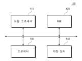
도 1은 본 기재의 실시 예에 따른 전자 장치(10)의 블록도를 도시한다. 도 1을 참조하면, 전자 장치(10)는 뉴럴 프로세서(Neural Processor; 또는 Neural Processing Unit; 110), RAM(Random Access Memory; 120), 프로세서(130), 및 저장 장치(140)를 포함할 수 있다.Figure 1 shows a block diagram of an electronic device 10 according to an embodiment of the present disclosure. Referring to FIG. 1, the electronic device 10 may include a neural processor (or neural processing unit) 110, a random access memory (RAM) 120, a
뉴럴 프로세서(110)는 프로세서(130)의 제어 하에, 다양한 뉴럴 네트워크 알고리즘을 기반으로 추론 동작을 수행할 수 있다. 예를 들어, 뉴럴 프로세서(110)는 스파이킹 뉴럴 네트워크(Spiking Neural Network; SNN)에 기반한 다양한 연산들을 수행할 수 있다. 뉴럴 프로세서(110)는 뉴럴 네트워크에 기반한 연산들을 처리하기 위한 뉴런 회로들을 포함할 수 있다. 뉴런 회로들은 호지킨-헉슬리 모델(Hodgkin-Huxley Model)(HHM)에 기반하여 구현될 수 있다.The
RAM(120)은 뉴럴 프로세서(110) 또는 프로세서(130)에 의해 처리될 예정인 데이터, 뉴럴 프로세서(110) 또는 프로세서(130)에 의해 실행될 수 있는 다양한 프로그램 코드들 또는 명령어들, 또는 뉴럴 프로세서(110) 또는 프로세서(130)에 의해 처리된 데이터를 저장할 수 있다. RAM(120)은 SRAM(Static Random Access Memory) 또는 DRAM(Dynamic Random Access Memory)을 포함할 수 있다The
프로세서(130)는 전자 장치(10)의 동작에 필요한 다양한 연산들을 수행할 수 있다. 예를 들어, 프로세서(130)는 RAM(120)에 로드된 펌웨어, 소프트웨어, 또는 프로그램 코드들을 실행할 수 있다. 프로세서(130)는 RAM(120)에 로드된 펌웨어, 소프트웨어, 또는 프로그램 코드들을 실행함으로써, 전자 장치(10)를 제어할 수 있다. 프로세서(130)는 실행들의 결과를 RAM(120) 또는 저장 장치(140)에 저장할 수 있다.The
저장 장치(140)는 뉴럴 프로세서(110) 또는 프로세서(130)가 연산을 수행하는 데 필요한 데이터 또는 정보를 저장할 수 있다. 저장 장치(140)는 뉴럴 프로세서(110) 또는 프로세서(130)에 의해 처리된 데이터를 저장할 수 있다. 저장 장치(140)는 뉴럴 프로세서(110) 또는 프로세서(130)에 의해 실행될 수 있는 소프트웨어, 펌웨어, 프로그램 코드, 또는 명령어들을 저장할 수 있다. 저장 장치(140)는 DRAM, SRAM 등과 같은 휘발성 메모리 또는 플래시 메모리 등과 같은 불휘발성 메모리일 수 있다.The
도 2는 본 기재의 실시 예에 따른 뉴럴 네트워크(200)를 도시한다. 뉴럴 네트워크(200)는 뉴럴 프로세서(110)에 의해 구현될 수 있다. 도 1 및 도 2를 참조하면, 뉴럴 네트워크(200)는 스파이킹 뉴럴 네트워크일 수 있다.Figure 2 shows a
뉴럴 네트워크(200)는 입력 뉴런 레이어(210), 시냅틱 웨이트 레이어(220), 및 출력 뉴런 레이어(230)를 포함할 수 있다. 뉴럴 프로세서(110)는 뉴럴 네트워크 연산들을 입력 서브젝트들(또는 입력 데이터)에 기반하여 수행하고, 그리고 출력 데이터를 수행 결과에 기반하여 생성할 수 있다.The
입력 뉴런 레이어(210)는 하나 이상의 입력 뉴런들(neurons)을 포함할 수 있고, 그리고 출력 뉴런 레이어(230)는 하나 이상의 출력 뉴런들을 포함할 수 있다. 시냅틱 웨이트 레이어(220)는 입력 뉴런들 및 출력 뉴런들 사이의 연결 강도를 결정할 수 있는 시냅틱 웨이트들(synaptic weights)을 포함할 수 있다. 하나의 입력 뉴런은 모든 출력 뉴런들로 시냅스를 통해 연결될 수 있다. 입력 뉴런은 대응하는 시냅틱 웨이트의 값에 기반하여, 스파이크 신호를 출력 뉴런들로 각각 전달할 수 있다.The
입력 뉴런들 또는 출력 뉴런들의 각각은 뉴런 회로를 포함할 수 있다. 뉴런 회로는 HHM에 기반하여 스파이킹 신호를 생성 또는 전달할 수 있다. 연산 복잡도 또는 연산량을 줄이기 위하여, 뉴런 회로들은 로그 기반 그리고 바이어스 기반으로 스파이킹 신호를 생성 또는 전달할 수 있다.Each of the input neurons or output neurons may include a neuron circuit. Neuron circuits can generate or transmit spiking signals based on HHM. To reduce computational complexity or amount of computation, neuron circuits can generate or transmit spiking signals on a logarithmic basis and a bias basis.
도 3은 본 기재의 실시 예에 따른 뉴런 회로(300)를 보여준다. 도 3을 참조하면, 뉴런 회로(300)는 스파이킹 신호를 생성 또는 전달할 수 있다. 뉴런 회로(300)는 로그 기반 뉴런 계산 회로(310), 제1 바이어스 회로(320), 그리고 제2 바이어스 회로(330)를 포함할 수 있다.Figure 3 shows a
로그 기반 뉴런 계산 회로(310)는 HMM에 기반하여 구현될 수 있다. HMM은 로그 기반으로 동작하도록 구현되어, 연산 복잡도를 낮출 수 있다. 로그 기반 뉴런 계산 회로(310)는 바이어스된 입력 전류(iI)로부터 바이어스된 출력 전류(v)를 생성할 수 있다.The log-based
제1 바이어스 회로(320)는 입력 전류(ii)에 바이어스 전류(iB)를 더하여 바이어스된 입력 전류(iI)를 생성할 수 있다. 제1 바이어스 회로(320)는 로그 기반 뉴런 계산 회로(310)가 정상 동작하도록, 입력 전류(ii)에 바이어스 전류(IB)를 더하여, 양의 범위에 속하는 바이어스된 입력 전류(iI)를 생성할 수 있다. 바이어스 전류(IB)는 약 10uA일 수 있다.The
제2 바이어스 회로(330)는 바이어스된 출력 전류(v)로부터 바이어스 전압(vB)을 감하여 출력 전압(vo)을 생성할 수 있다. 제2 바이어스 회로(330)는 바이어스된 전압(v)을 역 바이어스 함으로써 바이어스를 제거할 수 있다. 바이어스 전압(vB)은 96mV일 수 있다.The
이하에서, 로그 기반 뉴런 계산 회로(310)의 구현을 위한 수학식들이 정의된다. 선행기술문헌 1을 참조하면, HMM의 뉴런 모델은 수학식 1로 정의될 수 있다.Below, equations for implementing the log-based
선행기술문헌 2를 참조하면, 수학식 1의 HMM 모델은 표기법을 정리함으로써 수학식 2로 변경될 수 있다.Referring to Prior Art Document 2, the HMM model in Equation 1 can be changed to Equation 2 by organizing the notation.
선행기술문헌 3을 참조하면, 뉴런의 휴지기 전압을 -64mV로 정의함으로써, 수학식 2는 수학식 3으로 변경될 수 있다.Referring to
도 3에 도시된 바와 같이 바이어스 전류(IB)에 의해 입력 전류(ii)가 바이어스되면, 수학식 3에도 바이어스 전류(IB)의 영향이 반영되어 수학식 3이 수학식 4로 변경될 수 있다.As shown in FIG. 3, when the input current (ii) is biased by the bias current (IB ), the influence of the bias current (IB ) is also reflected in
수학식 4에서, 단위 면적당 멤브레인 커패시턴스(cm)는 1.0일 수 있다. 단위 면적당 칼륨 컨덕턴스(gK)는 36.0일 수 있다. 단위 면적당 나트륨 컨덕턴스(gNa)는 120.0일 수 있다. 단위 면적당 누설 컨덕턴스(gL)는 0.3일 수 있다. 칼륨 반전 전위(vK)는 19일 수 있다. 나트륨 반전 전위(vNa)는 146일 수 있다. 누설 반전 전위(vL)는 41.613일 수 있다.In Equation 4, the membrane capacitance per unit area (cm ) may be 1.0. Potassium conductance per unit area (gK ) may be 36.0. Sodium conductance per unit area (gNa ) may be 120.0. Leakage conductance per unit area (gL ) may be 0.3. The potassium inversion potential (vK ) may be 19. The sodium inversion potential (vNa ) may be 146. The leakage reversal potential (vL ) may be 41.613.
수학식 4의 값들은 실수 값들이며, 소문자들로 표시될 수 있다. 수학식 4를 로그 영역으로 변환하면, 수학식 4는 수학식 5로 변경될 수 있다.The values in Equation 4 are real numbers and can be displayed with lowercase letters. If Equation 4 is converted to the logarithmic domain, Equation 4 can be changed to Equation 5.
수학식 5의 값들은 지수 로그 값들이며, 대문자들로 표시될 수 있다. 수학식 4를 수학식 5로 변환하는 과정에서, 수학식 4와 연관되어 설명된 HHM의 특색 값들, 예를 들어 단위 면적당 칼륨 컨덕턴스(gK), 단위 면적당 나트륨 컨덕턴스(gNa), 단위 면적당 누설 컨덕턴스(gL), 칼륨 반전 전위(vK), 나트륨 반전 전위(vNa), 그리고 누설 반전 전위(vL)가 대략적인 값들로 반영될 수 있다. 또한, 실수들의 곱셈들 및 나눗셈들은 로그 영역의 덧셈들 및 뺄셈들로 변경될 수 있다.The values in Equation 5 are exponential log values and can be indicated with uppercase letters. In the process of converting Equation 4 to Equation 5, the characteristic values of HHM described in relation to Equation 4, such as potassium conductance per unit area (gK ), sodium conductance per unit area (gNa ), and leakage per unit area Conductance (gL ), potassium reversal potential (vK ), sodium reversal potential (vNa ), and leakage reversal potential (vL ) can be reflected as approximate values. Additionally, multiplications and divisions of real numbers can be converted to additions and subtractions in the logarithmic domain.
연산자()는 자코비안(Jacobian) 덧셈 또는 자코비안 덧셈기일 수 있다. 자코비안 덧셈()은 자코비안 덧셈기()의 입력들의 값들의 지수승들의 합의 지수 로그를 계산하는 것을 포함할 수 있다. 자코비안 덧셈()은 수학식 6으로 정의될 수 있다.Operator( ) may be Jacobian addition or Jacobian adder. Jacobian addition ( ) is a Jacobian adder ( ) may include calculating the logarithm of the exponent of the sum of exponents of the values of the inputs. Jacobian addition ( ) can be defined as Equation 6.
연산자()는 자코비안 뺄셈 또는 자코비안 뺄셈기일 수 있다. 자코비안 뺄셈()은 자코비안 뺄셈기()의 제1 입력의 값이 제2 입력의 값보다 클 때에 제1 입력의 값의 지수승으로부터 제2 입력의 값의 지수승을 감한 값의 지수로그 값을 계산하고, 자코비안 뺄셈기()의 제1 입력의 값이 제2 입력의 값보다 크지 않을 때에 제2 입력의 값의 지수승으로부터 제1 입력의 값의 지수승을 감한 값의 지수로그 값을 계산하고, 자코비안 뺄셈기()의 제1 입력의 값이 제2 입력의 값과 같거나 그보다 클 때에 양의 부호를 계산하고, 그리고 자코비안 뺄셈기()의 제1 입력의 값이 제2 입력의 값보다 작을 때에 음의 부호를 계산하는 것을 포함할 수 있다. 자코비안 뺄셈()은 수학식 7로 정의될 수 있다.Operator( ) can be Jacobian subtraction or Jacobian subtractor. Jacobian subtraction ( ) is the Jacobian subtractor ( When the value of the first input is greater than the value of the second input, the logarithm of the exponent is calculated by subtracting the exponent of the value of the second input from the exponent of the value of the first input, and a Jacobian subtractor ( When the value of the first input is not greater than the value of the second input, the logarithm of the exponent is calculated by subtracting the exponent of the value of the first input from the exponent of the value of the second input, and a Jacobian subtractor ( When the value of the first input of ) is equal to or greater than the value of the second input, the positive sign is calculated, and the Jacobian subtractor ( ) may include calculating a negative sign when the value of the first input is less than the value of the second input. Jacobian subtraction ( ) can be defined as Equation 7.
로그 기반 뉴런 계산 회로(310)는 수학식 5에 기반하여 감소된 연산 복잡도로 구현될 수 있다.The log-based
도 4는 뉴런 회로(300)의 동작 방법의 예를 보여준다. 도 3 및 도 4를 참조하면, S110 단계에서, 제1 바이어스 회로(320)는 입력 전류(ii)에 바이어스 전류(IB)를 인가하여 바이어스된 입력 전류(iI)를 생성할 수 있다.Figure 4 shows an example of how the
S120 단계에서, 로그 기반 뉴런 계산 회로(310)는 바이어스된 입력 전류(iI)의 값(예를 들어 전류량의 값)의 지수 로그 값(예를 들어, 입력 로그 값)을 계산하고, 그리고 바이어스된 입력 전류(iI)의 지수 로그 값에 기반하여 바이어스된 스파이크 신호에 대응하는 전압의 값(예를 들어, 전압 레벨)의 지수 로그 값들 계산하고, 그리고 바이어스된 스파이크 신호에 대응하는 전압의 값의 지수 로그 값의 지수승을 계산하여 바이어스된 출력 전압(v)을 출력할 수 있다. 출력 전압(v)은 바이어스된 스파이크 신호에 대응하는 전압일 수 있다.In step S120, the log-based
S130 단계에서, 제2 바이어스 회로(330)는 출력 전압(v)에 바이어스 전압(vB)을 인가하여, 예를 들어 출력 전압(v)으로부터 바이어스 전압(vB)을 감하여 출력 전압(vo)을 생성할 수 있다. 출력 전압(vo)은 스파이크 신호에 대응하는 전압일 수 있다.In step S130, the
도 5는 로그 기반 뉴런 계산 회로(310)의 예를 보여준다. 도 5 및 수학식 5를 참조하면, 로그 기반 뉴런 계산 회로(310)는 계산 회로(400) 및 메모리(450)를 포함할 수 있다. 계산 회로(400)는 바이어스된 입력 전류(iI)로부터 바이어스된 출력 전압(v)을 계산할 수 있다. 메모리(450)는 계산 회로(400)의 계산 과정에 필요한 다양한 값들을 저장하고, 그리고 계산 회로(400)에 제공할 수 있다.Figure 5 shows an example of a log-based
제1 내지 제6 1차 계산기들(411~416), 제1 내지 제3 2차 계산기들(421~423), 입력 계산기(401), 3차 계산기(430), 그리고 출력 계산기(440)를 포함할 수 있다.First to sixth
제1 1차 계산기(411)는 이전 사이클의 바이어스된 출력 전압의 지수 로그 값(V) 및 이전 사이클의 바이어스된 출력 전압의 반전 값(-v)에 기반하여 제1 매개변수(AN)를 생성할 수 있다.The first
제2 1차 계산기(412)는 이전 사이클의 바이어스된 출력 전압의 반전 값(-v)에 기반하여 제2 매개변수(BN)를 생성할 수 있다.The second
제3 1차 계산기(413)는 이전 사이클의 바이어스된 출력 전압의 지수 로그 값(V) 및 이전 사이클의 바이어스된 출력 전압의 반전 값(-v)에 기반하여 제3 매개 변수(AM)를 생성할 수 있다.The third
제4 1차 계산기(414)는 이전 사이클의 바이어스된 출력 전압의 반전 값(-v)에 기반하여 제4 매개변수(BM)를 생성할 수 있다.The fourth
제5 1차 계산기(415)는 이전 사이클의 상기 바이어스된 출력 전압의 반전 값(-v)에 기반하여 제5 매개변수(AH)를 생성할 수 있다.The fifth
제6 1차 계산기(416)는 이전 사이클의 바이어스된 출력 전압의 반전 값(-v)에 기반하여 제6 매개변수(BH)를 생성할 수 있다.The sixth
제1 2차 계산기(421)는 제1 매개변수(AN)가 입력되는 제1 매개변수 입력, 제2 매개변수(BN)가 입력되는 제2 매개변수 입력, 그리고 제7 매개변수(N)가 출력되는 매개변수 출력을 포함할 수 있다. 제1 2차 계산기(421)는 제1 매개변수(AN), 제2 매개변수(BN), 제7 매개변수의 초기값(N0), 그리고 이전 사이클과 현재 사이클 사이의 시간 차이의 지수 로그 값(△T)에 기반하여 현재 사이클의 제7 매개변수(N)를 계산할 수 있다.The first
제2 2차 계산기(422)는 제3 매개변수(AM)가 입력되는 제1 매개변수 입력, 제4 매개변수(BM)가 입력되는 제2 매개변수 입력, 그리고 제8 매개변수(M)가 출력되는 매개변수 출력을 포함할 수 있다. 제3 매개변수(AM), 제4 매개변수(BM), 제8 매개변수의 초기값(M0), 그리고 시간 차이의 지수 로그 값(△T)에 기반하여 현재 사이클의 제8 매개변수(M)를 계산할 수 있다.The second
제3 2차 계산기(423)는 제5 매개변수(AH)가 입력되는 제1 매개변수 입력, 제6 매개변수(BH)가 입력되는 제2 매개변수 입력, 그리고 제9 매개변수(H)가 출력되는 매개변수 출력을 포함할 수 있다. 제5 매개변수(AH), 제6 매개변수(BH), 제9 매개변수의 초기값(H0), 그리고 시간 차이의 지수 로그 값(△T)에 기반하여 현재 사이클의 제9 매개변수(H)를 계산할 수 있다.The third
입력 계산기는 제7 내지 제9 매개변수들(N, M H), 이전 사이클의 바이어스된 출력 전압의 지수 로그 값(V), 그리고 바이어스된 입력 전류(IB)에 기반하여 제10 매개변수(IP) 및 제11 매개변수(IN)를 생성할 수 있다.Theinput calculator calculates the tenth parameter (IP ) and the 11th parameter (IN ) can be created.
3차 계산기는 제10 매개변수(IP), 제11 매개변수(IN), 바이어스된 출력 전압의 초기값의 지수 로그 값(V0) 및 시간 차이의 지수 로그 값(△T)에 기반하여 현재 사이클의 바이어스된 출력 전압의 지수 로그 값(V)(또는 수학식 5의 V(t+△t))을 생성할 수 있다.The third-order calculator is based on the 10th parameter (IP ), the 11th parameter (IN ), the exponential logarithm of the initial value of the biased output voltage (V0 ), and the exponential logarithm of the time difference (△T) Thus, the exponential log value (V) of the biased output voltage of the current cycle (or V(t+Δt) in Equation 5) can be generated.
출력 계산기(440)는 현재 사이클의 바이어스된 출력 전압의 지수 로그 값(V)(또는 수학식 5의 V(t+△t))에 기반하여, 현재 사이클의 바이어스된 출력 전압(v) 및 현재 사이클의 바이어스된 출력 전압의 반전 값(-v)을 생성할 수 있다. '현재 사이클의 바이어스된 출력 전압'은 'v(t+△t)'로 표시될 수도 있다. '현재 사이클의 바이어스된 출력 전압의 반전 값'은 '-v(t+△t)'로 표시될 수도 있다.
도 6은 제1 1차 계산기(411)의 예를 보여준다. 도 5 및 도 6을 참조하면, 제1 1차 계산기(411)는 선택 회로(511), 제1 멀티플렉서(512), 제3 멀티플렉서(513), 제1 자코비안 뺄셈기(514), 제1 뺄셈기(515), 곱셈기(516), 제3 멀티플렉서(517), 제4 멀티플렉서(518), 제2 자코비안 뺄셈기(519), 제2 뺄셈기(520), 그리고 덧셈기(521)를 포함할 수 있다.Figure 6 shows an example of the first
선택 회로(511)는 이전 사이클의 바이어스된 출력 전압의 지수 로그 값(V) 및 'ln41'의 값을 수신할 수 있다. 'ln41'의 값은 상수이며, 메모리(450)로부터 제공될 수 있다. 따라서, 'ln41'의 값은 계산 회로(400)의 연산량 또는 연산 복잡도를 증가시키지 않을 수 있다. 메모리(450)로부터 제공되는 값은 'ln41'의 결과값을 특정 자릿수에서 내림, 올림 또는 반올림한 값일 수 있다.The
선택 회로(511)는 이전 사이클의 바이어스된 출력 전압의 지수 로그 값(V)이 약 'ln41'의 값보다 클 때에(또는 이상일 때에) 제1 입력들을 출력들에 연결하고, 그리고 이전 사이클의 바이어스된 출력 전압의 지수 로그 값(V)이 약 'ln41'의 값보다 크지 않을 때에(또는 작을 때에) 제2 입력들을 출력들에 연결하도록 상기 제1 내지 제4 멀티플렉서들(512, 513, 517, 518)을 제어할 수 있다.The
제1 멀티플렉서(512)는 약 'ln41'의 값이 입력되는 제1 입력 및 이전 사이클의 바이어스된 출력 전압의 지수 로그 값(V)이 입력되는 제2 입력을 포함할 수 있다. 선택 회로(511)의 제어에 따라, 제1 멀티플렉서(512)는 제1 입력 또는 제2 입력의 값을 출력으로 전달할 수 있다.The
제2 멀티플렉서(513)는 이전 사이클의 상기 바이어스된 출력 전압의 지수 로그 값(V)이 입력되는 제1 입력 및 약 'ln41'의 값이 입력되는 제2 입력을 포함할 수 있다. 선택 회로(512)의 제어에 따라, 제2 멀티플렉서(513)는 제1 입력 또는 제2 입력의 값을 출력으로 전달할 수 있다.The
제1 자코비안 뺄셈기(514)는 제1 멀티플렉서의 출력이 입력되는 제1 입력 및 제2 멀티플렉서의 출력이 입력되는 제2 입력을 포함할 수 있다. 제1 자코비안 뺄셈기(514)는 제1 입력의 값 및 상기 제2 입력의 값에 대해 자코비안 뺄셈을 수행하여 출력할 수 있다.The first
제1 뺄셈기(515)는 약 '41'의 값으로부터 바이어스된 출력 전압(v)의 값을 감하여 출력할 수 있다. '41'의 값은 상수이며, 메모리(450)로부터 제공될 수 있다. 메모리(450)로부터 제공되는 값은 '41'의 값을 특정 자릿수에서 내림, 올림 또는 반올림한 값일 수 있다.The
곱셈기(516)는 제1 뺄셈기(515)의 출력에 약 '0.1'의 값을 곱하여 출력할 수 있다. '0.1'의 값은 상수이며, 메모리(450)로부터 제공될 수 있다. 메모리(450)로부터 제공되는 값은 '0.1'의 값을 특정 자릿수에서 내림, 올림 또는 반올림한 값일 수 있다.The
제3 멀티플렉서(517)는 곱셈기(516)의 출력이 입력되는 제1 입력 및 약 '0'의 값이 입력되는 제2 입력을 포함할 수 있다. '0'의 값은 상수이며, 메모리(450)로부터 제공될 수 있다. 선택 회로(512)의 제어에 따라, 제3 멀티플렉서(517)는 제1 입력 또는 제2 입력의 값을 출력으로 전달할 수 있다.The
제4 멀티플렉서(518)는 약 '0'의 값이 입력되는 제1 입력 및 곱셈기(516)의 출력이 입력되는 제2 입력을 포함할 수 있다. 선택 회로(512)의 제어에 따라, 제4 멀티플렉서(518)는 제1 입력 또는 제2 입력의 값을 출력으로 전달할 수 있다.The
제2 자코비안 뺄셈기(519)는 제3 멀티플렉서(517)의 출력이 입력되는 제1 입력 및 제4 멀티플렉서(518)의 출력이 입력되는 제2 입력을 포함할 수 있다. 제2 자코비안 뺄셈기(519)는 제1 입력의 값 및 제2 입력의 값에 대해 상기 자코비안 뺄셈을 수행하여 출력할 수 있다.The second
제2 뺄셈기(520)는 제1 자코비안 뺄셈기(514)의 출력으로부터 제2 자코비안 뺄셈기(519)의 출력을 감하여 출력할 수 있다.The
덧셈기(521)는 뺄셈기(520)의 출력에 약 'ln0.01'의 값을 더하여 제1 매개변수(AN)로 출력할 수 있다. 'ln0.01'의 값은 상수이며, 메모리(450)로부터 제공될 수 있다. 메모리(450)로부터 제공되는 값은 'ln0.01'의 결과값을 특정 자릿수에서 내림, 올림 또는 반올림한 값일 수 있다.The
도 7은 제2 1차 계산기(412)의 예를 보여준다. 도 5 및 도 7을 참조하면, 제2 1차 계산기(412)는 이전 사이클의 바이어스된 출력 전압의 반전 값(-v)에 약 '31'의 값을 더하는 덧셈기(531)를 포함할 수 있다. '31'의 값은 상수이며, 메모리(450)로부터 제공될 수 있다. 메모리(450)로부터 제공되는 값은 '31'의 값을 특정 자릿수에서 내림, 올림 또는 반올림한 값일 수 있다.Figure 7 shows an example of a second
제2 1차 계산기(412)는 덧셈기(531)의 출력에서 약 'ln8'의 값을 감하여 상기 제2 매개변수(BN)로 출력하는 뺄셈기를 더 포함할 수 있다. 'ln8'의 값은 상수이며, 메모리(450)로부터 제공될 수 있다. 메모리(450)로부터 제공되는 값은 'ln8'의 결과값을 특정 자릿수에서 내림, 올림 또는 반올림한 값일 수 있다.The second
도 8은 제3 1차 계산 회로(413)의 예를 보여준다. 도 5 및 도 8을 참조하면, 제3 1차 계산기는(413)는 선택 회로(541), 제1 멀티플렉서(542), 제2 멀티플렉서(543), 제1 자코비안 뺄셈기(544), 제1 뺄셈기(545), 곱셈기(546), 제3 멀티플렉서(547), 제4 멀티플렉서(548), 제2 자코비안 뺄셈기(549), 제2 뺄셈기(550), 그리고 덧셈기(551)를 포함할 수 있다.Figure 8 shows an example of the third
선택 회로(541)는 이전 사이클의 바이어스된 출력 전압의 지수 로그 값(V) 및 'ln56'의 값을 수신할 수 있다. 'ln56'의 값은 상수이며, 메모리(450)로부터 제공될 수 있다. 메모리(450)로부터 제공되는 값은 'ln56'의 결과값을 특정 자릿수에서 내림, 올림 또는 반올림한 값일 수 있다.The
선택 회로(541)는 이전 사이클의 바이어스된 출력 전압의 지수 로그 값(V)이 약 'ln56'의 값보다 클 때에(또는 이상일 때에) 제1 입력들을 출력들에 연결하고, 그리고 이전 사이클의 바이어스된 출력 전압의 지수 로그 값(V)이 약 'ln56'의 값보다 크지 않을 때에(또는 작을 때에) 제2 입력들을 출력들에 연결하도록 상기 제1 내지 제4 멀티플렉서들(542, 543, 547, 548)을 제어할 수 있다.
제1 멀티플렉서(542)는 약 'ln56'의 값이 입력되는 제1 입력 및 이전 사이클의 바이어스된 출력 전압의 지수 로그 값(V)이 입력되는 제2 입력을 포함할 수 있다. 선택 회로(541)의 제어에 따라, 제1 멀티플렉서(542)는 제1 입력 또는 제2 입력의 값을 출력으로 전달할 수 있다.The
제2 멀티플렉서(543)는 이전 사이클의 상기 바이어스된 출력 전압의 지수 로그 값(V)이 입력되는 제1 입력 및 약 'ln56'의 값이 입력되는 제2 입력을 포함할 수 있다. 선택 회로(541)의 제어에 따라, 제1 멀티플렉서(542)는 제1 입력 또는 제2 입력의 값을 출력으로 전달할 수 있다.The
제1 자코비안 뺄셈기(544)는 제1 멀티플렉서(542)의 출력이 입력되는 제1 입력 및 제2 멀티플렉서(543)의 출력이 입력되는 제2 입력을 포함할 수 있다. 제1 자코비안 뺄셈기(544)는 제1 입력의 값 및 제2 입력의 값에 대해 자코비안 뺄셈을 수행하여 출력할 수 있다.The first
제1 뺄셈기(545)는 약 '56'의 값으로부터 상기 바이어스된 출력 전압의 값을 감하여 출력할 수 있다. '56'의 값은 상수이며, 메모리(450)로부터 제공될 수 있다. 메모리(450)로부터 제공되는 값은 '56'의 값을 특정 자릿수에서 내림, 올림 또는 반올림한 값일 수 있다.The
곱셈기(546)는 제1 뺄셈기(545)의 출력에 약 '0.1'의 값을 곱하여 출력할 수 있다. '0.1'의 값은 상수이며, 메모리(450)로부터 제공될 수 있다. 메모리(450)로부터 제공되는 값은 '0.1'의 값을 특정 자릿수에서 내림, 올림 또는 반올림한 값일 수 있다.The
제3 멀티플렉서(547)는 곱셈기(546)의 출력이 입력되는 제1 입력 및 약 '0'의 값이 입력되는 제2 입력을 포함할 수 있다. '0'의 값은 상수이며, 메모리(450)로부터 제공될 수 있다. 선택 회로(541)의 제어에 따라, 제3 멀티플렉서(547)는 제1 입력 또는 제2 입력의 값을 출력으로 전달할 수 있다.The
제4 멀티플렉서(548)는 약 '0'의 값이 입력되는 제1 입력 및 곱셈기(546)의 출력이 입력되는 제2 입력을 포함할 수 있다. 선택 회로(541)의 제어에 따라, 제4 멀티플렉서(548)는 제1 입력 또는 제2 입력의 값을 출력으로 전달할 수 있다.The
제2 자코비안 뺄셈기(549)는 제3 멀티플렉서(547)의 출력이 입력되는 제1 입력 및 제4 멀티플렉서(548)의 출력이 입력되는 제2 입력을 포함할 수 있다. 제2 자코비안 뺄셈기(549)는 제1 입력의 값 및 제2 입력의 값에 대해 자코비안 뺄셈을 수행하여 출력할 수 있다.The second
제2 뺄셈기(550)는 제1 자코비안 뺄셈기(544)의 출력으로부터 제2 자코비안 뺄셈기(549)의 출력을 감하여 출력할 수 있다.The
덧셈기(551)는 뺄셈기(550)의 출력에 약 'ln0.1'의 값을 더하여 제3 매개변수(AM)로 출력할 수 있다. 'ln0.1'의 값은 상수이며, 메모리(450)로부터 제공될 수 있다. 메모리(450)로부터 제공되는 값은 'ln0.1'의 결과값을 특정 자릿수에서 내림, 올림 또는 반올림한 값일 수 있다.The
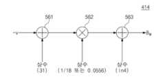
도 9는 제4 1차 계산기(414)의 예를 보여준다. 도 5 및 도 9를 참조하면, 제4 1차 계산기(414)는 제1 덧셈기(561), 곱셈기(562), 그리고 제2 덧셈기(563)를 포함할 수 있다.Figure 9 shows an example of the fourth
제1 덧셈기(561)는 이전 사이클의 바이어스된 출력 전압의 반전 값(-v)에 약 '31'의 값을 더하여 출력할 수 있다. '31'의 값은 상수이며, 메모리(450)로부터 제공될 수 있다. 메모리(450)로부터 제공되는 값은 '31'의 값을 특정 자릿수에서 내림, 올림 또는 반올림한 값일 수 있다.The
곱셈기(562)는 제1 덧셈기(561)의 출력에 약 '1/18' 또는 약 '0.0556'의 값을 곱하여 출력할 수 있다. 약 '1/18' 또는 약 '0.0556'의 값은 상수이며, 메모리(450)로부터 제공될 수 있다. 메모리(450)로부터 제공되는 값은 약 '1/18' 또는 약 '0.0556'의 값을 특정 자릿수에서 내림, 올림 또는 반올림한 값일 수 있다.The
제2 덧셈기(563)는 곱셈기(562)의 출력에 약 'ln4'의 값을 더하여 제4 매개변수(BM)로 출력할 수 있다. 'ln4'의 값은 상수이며, 메모리(450)로부터 제공될 수 있다. 메모리(450)로부터 제공되는 값은 'ln4'의 결과값을 특정 자릿수에서 내림, 올림 또는 반올림한 값일 수 있다.The
도 10은 제5 1차 계산기(415)의 예를 보여준다. 도 5 및 도 10을 참조하면, 제5 1차 계산기(415)는 제1 덧셈기(566), 곱셈기(567), 그리고 제2 덧셈기(568)를 포함할 수 있다.Figure 10 shows an example of the fifth
제1 덧셈기(566)는 이전 사이클의 바이어스된 출력 전압의 반전 값(-v)에 약 '31'의 값을 더하여 출력할 수 있다. '31'의 값은 상수이며, 메모리(450)로부터 제공될 수 있다. 메모리(450)로부터 제공되는 값은 '31'의 값을 특정 자릿수에서 내림, 올림 또는 반올림한 값일 수 있다.The
곱셈기(567)는 제1 덧셈기(566)의 출력에 약 '0.05'의 값을 곱하여 출력할 수 있다. '0.05'의 값은 상수이며, 메모리(450)로부터 제공될 수 있다. 메모리(450)로부터 제공되는 값은 '0.05'의 값을 특정 자릿수에서 내림, 올림 또는 반올림한 값일 수 있다.The
제2 덧셈기(568)는 곱셈기(567)의 출력에 약 'ln0.07'의 값을 더하여 제5 매개변수(AH)로 출력할 수 있다. 'ln0.07'의 값은 상수이며, 메모리(450)로부터 제공될 수 있다. 메모리(450)로부터 제공되는 값은 'ln0.07'의 결과값을 특정 자릿수에서 내림, 올림 또는 반올림한 값일 수 있다.The
도 11은 제6 1차 계산기의 예를 보여준다. 도 5 및 도 11을 참조하면, 제6 1차 계산기(416)는 덧셈기(571), 곱셈기(572), 자코비안 덧셈기(573), 그리고 제2 곱셈기(574)를 포함할 수 있다.Figure 11 shows an example of a sixth order calculator. Referring to FIGS. 5 and 11 , the sixth
덧셈기(571)는 이전 사이클의 바이어스된 출력 전압의 반전 값(-v)에 약 '61'의 값을 더하여 출력할 수 있다. '61'의 값은 상수이며, 메모리(450)로부터 제공될 수 있다. 메모리(450)로부터 제공되는 값은 '61'의 값을 특정 자릿수에서 내림, 올림 또는 반올림한 값일 수 있다.The
제1 곱셈기(572)는 제1 덧셈기(571)의 출력에 약 '0.1'의 값을 곱하여 출력할 수 있다. '0.1'의 값은 상수이며, 메모리(450)로부터 제공될 수 있다. 메모리(450)로부터 제공되는 값은 '0.1'의 값을 특정 자릿수에서 내림, 올림 또는 반올림한 값일 수 있다.The
자코비안 덧셈기(573)는 곱셈기(572)의 출력이 입력되는 제1 입력 및 약 'ln4'의 값이 입력되는 제2 입력을 포함할 수 있다. 'ln4'의 값은 상수이며, 메모리(450)로부터 제공될 수 있다. 메모리(450)로부터 제공되는 값은 'ln4'의 결과값을 특정 자릿수에서 내림, 올림 또는 반올림한 값일 수 있다. 자코비안 덧셈기(573)는 제1 입력의 값 및 제2 입력의 값에 대해 자코비안 덧셈을 수행하여 출력할 수 있다.The
제2 곱셈기(574)는 자코비안 덧셈기(573)의 출력에 약 '-1'의 값을 곱하여 제6 매개변수(BH)로 출력할 수 있다. '-1'의 값은 상수이며, 메모리(450)로부터 제공될 수 있다. 메모리(450)로부터 제공되는 값은 '-1'의 값을 특정 자릿수에서 내림, 올림 또는 반올림한 값일 수 있다.The
도 12는 제1 내지 제3 2차 계산기들(421, 422, 423) 중 어느 하나의 2차 계산기(421/422/423)의 예를 보여준다. 제1 내지 제3 2차 계산기들(421, 422, 423)은 동일한 구조들을 가질 수 있다.Figure 12 shows an example of one of the first to third
도 5 및 도 12를 참조하면, 2차 계산기(421/422/423)는 제1 자코비안 뺄셈기(581), 제1 덧셈기(582), 제2 덧셈기(583), 선택 회로(584), 제1 멀티플렉서(585), 제2 멀티플렉서(586), 제2 자코비안 뺄셈기(587), 제3 덧셈기(588), 자코비안 덧셈기(589), 제2 자코비안 뺄셈기(590), 제3 멀티플렉서, 그리고 변화량 계산기(592)를 포함할 수 있다.5 and 12, the
제1 자코비안 뺄셈기(581)는 '0'의 값이 입력되는 제1 입력 및 2차 계산기(421/422/423)의 이전 사이클의 매개변수 출력(X)(X는 N, M 및 H 중 하나)의 값이 입력되는 제2 입력을 포함하고, 그리고 제1 입력의 값 및 제2 입력의 값에 대해 자코비안 뺄셈을 수행할 수 있다. '0'의 값은 상수이며, 메모리(450)로부터 제공될 수 있다.The first
제1 덧셈기(582)는 2차 계산기(421/422/423)의 제1 매개변수 입력의 값(AX)(X는 N, M 및 H 중 하나)과 제1 자코비안 뺄셈기(581)의 출력을 더하여 출력(A0)할 수 있다.The
제2 덧셈기(583)는 2차 계산기(421/422/423)의 제2 매개변수 입력의 값(BX)(X는 N, M 및 H 중 하나)과 2차 계산기(421/422/423)의 이전 사이클의 매개변수 출력(X)(X는 N, M 및 H 중 하나)의 값을 더하여 출력(B0)할 수 있다.The
선택 회로(584)는 제1 덧셈기(582)의 출력(A0) 및 제2 덧셈기(583)의 출력(B0)을 수신할 수 있다. 선택 회로(584)는 제1 덧셈기(582)의 출력(A0)이 제2 덧셈기(583)의 출력(B0)보다 클 때에(또는 이상일 때에) 제1 내지 제3 멀티플렉서들(585, 586, 591)이 제1 입력들의 값들을 출력하도록 제어하고, 그리고 제1 덧셈기(582)의 출력(A0)이 제2 덧셈기(583)의 출력(B0)보다 크지 않을 때에(또는 작을 때에) 제1 내지 제3 멀티플렉서들(585, 586, 591)이 제2 입력들의 값들을 출력하도록 제어할 수 있다. 선택 회로(584)의 출력은 제7 내지 제10 매개변수들(N, M, H) 중 어느 하나(X)의 순간 변화량(dX/dt)의 부호([dX/dt]S)에 대응할 수 있다.The
제1 멀티플렉서(585)는 제1 덧셈기(582)의 출력(A0)이 입력되는 제1 입력 및 제2 덧셈기(583)의 출력(B0)이 입력되는 제2 입력을 포함할 수 있다. 선택 회로(584)의 제어에 따라, 제1 멀티플렉서(585)는 제1 입력의 값 및 제2 입력의 값 중 하나를 출력할 수 있다.The
제2 멀티플렉서(586)는 제2 덧셈기(583)의 출력(B0)이 입력되는 제1 입력 및 제1 덧셈기(582)의 출력(A0)이 입력되는 제2 입력을 포함할 수 있다. 선택 회로(584)의 제어에 따라, 제2 멀티플렉서(586)는 제1 입력의 값 및 제2 입력의 값 중 하나를 출력할 수 있다.The
제2 자코비안 뺄셈기(587)는 제1 멀티플렉서(585)의 출력이 입력되는 제1 입력 및 제2 멀티플렉서(586)의 출력이 입력되는 제2 입력을 포함할 수 있다. 제2 자코비안 뺄셈기(587)는 제1 입력의 값 및 제2 입력의 값에 대해 자코비안 뺄셈을 수행하여 출력할 수 있다. 제2 자코비안 뺄셈기(587)의 출력은 제7 내지 제10 매개변수들(N, M, H) 중 어느 하나(X)의 순간 변화량(dX/dt)의 크기([dX/dt]M)에 대응할 수 있다.The second
제3 덧셈기(588)는 제2 자코비안 뺄셈기(587)의 출력([dX/dt]M)에 이전 사이클과 현재 사이클 사이의 시간 차이의 지수 로그 값(△T)을 더하여 출력할 수 있다. 시간 차이의 지수 로그 값(△T)은 상수 또는 변수일 수 있으며, 메모리(450)로부터 제공될 수 있다. 메모리(450)로부터 제공되는 시간 차이의 지수 로그 값(△T)의 값은 특정한 자릿수에서 올림, 내림 또는 반올림한 값일 수 있다.The
자코비안 덧셈기(589)는 제3 덧셈기(588)의 출력 및 이전 사이클의 매개변수 출력의 값(X)에 대해 자코비안 덧셈을 수행하여 출력할 수 있다.The
제3 자코비안 뺄셈기(590)는 제3 덧셈기(589)의 출력이 입력되는 제1 입력 및 이전 사이클의 매개변수 출력의 값(X)이 입력되는 제2 입력을 포함할 수 있다. 제3 자코비안 뺄셈기(590)는 제1 입력의 값 및 제2 입력의 값에 대해 자코비안 뺄셈을 수행하여 출력할 수 있다.The third
제3 멀티플렉서(591)는 자코비안 덧셈기(589)의 출력이 입력되는 제1 입력 및 제3 자코비안 뺄셈기(590)의 출력이 입력되는 제2 입력을 포함할 수 있다. 선택 회로(584)의 제어에 따라, 제3 멀티플렉서(591)는 제1 입력의 값 및 제2 입력의 값 중 하나를 출력할 수 있다.The
변화량 계산기(592)는 제3 멀티플렉서(591)의 출력에 제7 내지 제9 매개변수들(N, M, H)의 초기값들(N0, M0, H0) 중 대응하는 초기값(X0)에 기반하여, 시간 차이의 지수 로그 값(△T)에 대응하는 변화량을 계산할 수 있다. 초기값(X0)은 상수 또는 변수일 수 있으며, 메모리(450)로부터 제공될 수 있다. 메모리(450)로부터 제공되는 초기값(X0)은 특정한 자릿수에서 올림, 내림 또는 반올림한 값일 수 있다. 예를 들어, 변화량 계산기(592)는 오일러 방정식(또는 오일러 미분 방정식)에 기반하여 변화량을 계산할 수 있다. 변화량 계산기(592)는 초기값(X0)에 변화량을 합하여 제7 내지 제9 매개변수들(N, M, H) 중 대응하는 매개변수(X)로 출력할 수 있다.The
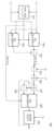
도 13은 입력 계산기(401)의 예를 보여준다. 도 5 및 도 13을 참조하면, 입력 계산기(401)는 제1 자코비안 뺄셈기(601), 제1 곱셈기(602), 제1 덧셈기(603), 제2 덧셈기(604), 제1 자코비안 덧셈기(605), 제3 덧셈기(606), 제2 자코비안 뺄셈기(607), 제3 자코비안 뺄셈기(608), 제4 자코비안 뺄셈기(609), 제4 덧셈기(610), 제2 곱셈기(611), 제5 덧셈기(612), 지수 로그 계산기(613), 그리고 제2 자코비안 덧셈기(614)를 포함할 수 있다.Figure 13 shows an example of
제1 자코비안 뺄셈기(601)는 이전 사이클의 바이어스된 출력 전압의 지수 로그 값(V)이 입력되는 제1 입력 및 칼륨 반전 전위(reversal potential)의 지수 로그 값(VK)이 입력되는 제2 입력을 포함하고, 그리고 제1 입력의 값 및 제2 입력의 값에 대해 자코비안(Jacobian) 뺄셈을 수행하여 출력할 수 있다. 칼륨 반전 전위의 지수 로그 값(VK)은 상수(예를 들어, ln19)일 수 있으며, 메모리(450)로부터 제공될 수 있다. 메모리(450)로부터 제공되는 칼륨 반전 전위의 지수 로그 값(VK)의 값은 특정한 자릿수에서 올림, 내림 또는 반올림한 값일 수 있다.The first
제1 곱셈기(602)는 제7 매개변수(N) 및 '4'의 값을 곱하여 출력할 수 있다. '4'의 값은 상수이며, 메모리(450)로부터 제공될 수 있다. 메모리(450)로부터 제공되는 값은 '4'의 값을 특정 자릿수에서 내림, 올림 또는 반올림한 값일 수 있다.The
제1 덧셈기(603)는 제1 자코비안 뺄셈기(601)의 출력, 제1 곱셈기(602)의 출력, 그리고 면적당 칼륨 컨덕턴스의 지수 로그 값(GK)을 합하여 출력할 수 있다. 면적당 칼륨 컨덕턴스의 지수 로그 값(GK)은 상수(예를 들어, ln36.0)일 수 있으며, 메모리(450)로부터 제공될 수 있다. 메모리(450)로부터 제공되는 면적당 칼륨 컨덕턴스의 지수 로그 값(GK)은 특정한 자릿수에서 올림, 내림 또는 반올림한 값일 수 있다. 제1 덧셈기(603)의 출력은 수학식 5의 IK에 대응할 수 있다.The
제2 덧셈기(604)는 이전 사이클의 바이어스된 출력 전압의 지수 로그 값(V) 및 면적당 누설 컨덕턴스의 지수 로그 값(GL)을 합하여 출력할 수 있다. 면적당 누설 컨덕턴스의 지수 로그 값(GL)은 상수(예를 들어, ln0.3)일 수 있으며, 메모리(450)로부터 제공될 수 있다. 메모리(450)로부터 제공되는 면적당 누설 컨덕턴스의 지수 로그 값(GL)은 특정한 자릿수에서 올림, 내림 또는 반올림한 값일 수 있다.The
제1 자코비안 덧셈기(605)는 제2 덧셈기(604)의 출력 및 바이어스 전류의 값의 지수 로그 값(IB)에 대해 자코비안 덧셈을 수행하여 출력할 수 있다. 바이어스 전류의 값의 지수 로그 값(IB)은 상수(예를 들어, ln10)일 수 있으며, 메모리(450)로부터 제공될 수 있다. 메모리(450)로부터 제공되는 바이어스 전류의 값의 지수 로그 값(IB)은 특정한 자릿수에서 올림, 내림 또는 반올림한 값일 수 있다.The first
제3 덧셈기(606)는 면적당 누설 컨덕턴스의 지수 로그 값(GL)과 누설 반전 전위의 지수 로그 값(VL)을 더하여 출력할 수 있다. 누설 반전 전위의 지수 로그 값(VL)은 상수(예를 들어, ln41.613)일 수 있으며, 메모리(450)로부터 제공될 수 있다. 메모리(450)로부터 제공되는 누설 반전 전위의 지수 로그 값(VL)은 특정한 자릿수에서 올림, 내림 또는 반올림한 값일 수 있다.The
제2 자코비안 뺄셈기(607)는 제1 자코비안 덧셈기(605)의 출력이 입력되는 제1 입력 및 제3 덧셈기(606)의 출력이 입력되는 제2 입력을 포함할 수 있다. 제2 자코비안 뺄셈기(607)는 제1 입력의 값 및 상기 제2 입력의 값에 대해 상기 자코비안 뺄셈을 수행하여 출력할 수 있다. 제2 자코비안 뺄셈기(607)의 출력은 수학식 5의 IL에 대응할 수 있다.The second
제3 자코비안 뺄셈기(608)는 제1 덧셈기(603)의 출력이 입력되는 제1 입력 및 제2 자코비안 뺄셈기(607)의 출력이 입력되는 제2 입력을 포함할 수 있다. 제3 자코비안 뺄셈기(608)는 제1 입력의 값 및 제2 입력의 값에 대해 자코비안 뺄셈을 수행하여 제10 매개변수(IP)로 출력할 수 있다.The third
제2 곱셈기(609)는 제8 매개변수(M)와 '3'의 값을 곱하여 출력할 수 있다. '3'의 값은 상수이며, 메모리(450)로부터 제공될 수 있다. 메모리(450)로부터 제공되는 값은 '3'의 값을 특정 자릿수에서 내림, 올림 또는 반올림한 값일 수 있다.The
제4 덧셈기(610)는 제2 곱셈기(609)의 출력과 제9 매개변수(H)를 더하여 출력할 수 있다.The
제4 자코비안 뺄셈기(611)는 이전 사이클의 바이어스된 출력 전압의 지수 로그 값(V)이 입력되는 제1 입력 및 칼륨 반전 전위의 지수 로그 값(VK)이 입력되는 제2 입력을 포함할 수 있다. 제4 자코비안 뺄셈기(611)는 제1 입력의 값 및 제2 입력의 값에 대해 상기 자코비안 뺄셈을 수행하여 출력할 수 있다.The fourth
제5 덧셈기(612)는 제4 자코비안 뺄셈기(611)의 출력, 면적당 나트륨 컨덕턴스의 지수 로그 값(GNa), 그리고 제4 덧셈기(610)의 출력을 더하여 출력할 수 있다. 면적당 나트륨 컨덕턴스의 지수 로그 값(GNa)은 상수(예를 들어, ln120.0)일 수 있으며, 메모리(450)로부터 제공될 수 있다. 메모리(450)로부터 제공되는 면적당 나트륨 컨덕턴스의 지수 로그 값(GNa)은 특정한 자릿수에서 올림, 내림 또는 반올림한 값일 수 있다. 제5 덧셈기(612)의 출력은 수학식 5의 '-INa'에 대응할 수 있다.The
지수 로그 계산기(613)는 바이어스된 입력 전류(iI)의 값(예를 들어, 전류량의 값)의 지수 로그 값(II)을 계산하여 출력할 수 있다.The
제2 자코비안 덧셈기(614)는 제5 덧셈기(612)의 출력 및 지수 로그 계산기(613)의 출력에 대해 자코비안 덧셈을 수행하여 제11 매개변수(IN)로 출력할 수 있다.The second
예시적으로, 제1 자코비안 뺄셈기(601) 및 제4 자코비안 뺄셈기(611)는 동일한 계산들을 수행한다. 따라서, 제1 자코비안 뺄셈기(601) 및 제4 자코비안 뺄셈기(611)는 하나의 자코비안 뺄셈기로 통합될 수 있다. 예를 들어, 제4 자코비안 뺄셈기(611)가 제거되고, 제4 자코비안 뺄셈기(611)의 출력 대신 제1 자코비안 뺄셈기(601)의 출력이 제5 덧셈기(612)에 제공될 수 있다.Exemplarily, the first
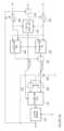
도 14는 3차 계산기(430)의 예를 보여준다. 도 5 및 도 14를 참조하면, 3차 계산기(430)는 선택 회로(621), 제1 멀티플렉서(622), 제2 멀티플렉서(623), 제1 자코비안 뺄셈기(624), 뺄셈기(625), 덧셈기(626), 자코비안 덧셈기(627), 제2 자코비안 뺄셈기(628), 제3 멀티플렉서(629), 그리고 변화량 계산기(630)를 포함할 수 있다.Figure 14 shows an example of a third-
선택 회로(621)는 제10 매개변수(IP) 및 제11 매개변수(IN)를 수신할 수 있다. 선택 회로(621)는 제10 매개변수(IP)가 제11 매개변수(IN) 이상일 때(또는 클 때)에 제1 입력들의 값들을 출력하고 그리고 제10 매개변수(IP)가 제11 매개변수(IN)보다 작을 때(또는 이하일 때)에 제2 입력들의 값들을 출력하도록 제1 내지 제3 멀티플렉서들(622, 623)을 제어할 수 있다. 선택 회로(621)의 출력은 바이어스된 출력 전압(V)의 순간 변화량(dV/dt)의 부호([dV/dt]S)에 대응할 수 있다.The
제1 멀티플렉서(622)는 제10 매개변수(IP)가 입력되는 제1 입력 및 제11 매개변수(IN)가 입력되는 제2 입력을 포함할 수 있다. 선택 회로(621)의 제어에 따라, 제1 멀티플렉서(622)는 제1 입력의 값 및 제2 입력의 값 중 하나를 출력할 수 있다.The
제2 멀티플렉서(623)는 제11 매개변수(IN)가 입력되는 제1 입력 및 제10 매개변수(IP)가 입력되는 제2 입력을 포함할 수 있다. 선택 회로(621)의 제어에 따라, 제1 멀티플렉서(622)는 제1 입력의 값 및 제2 입력의 값 중 하나를 출력할 수 있다.The
제1 자코비안 뺄셈기(624)는 제1 멀티플렉서(622)의 출력이 입력되는 제1 입력 및 제2 멀티플렉서(623)의 출력이 입력되는 제2 입력을 포함할 수 있다. 제1 자코비안 뺄셈기(624)는 제1 입력의 값 및 제2 입력의 값에 대해 자코비안 뺄셈을 수행하여 출력할 수 있다. 제1 자코비안 뺄셈기(624)의 출력은 바이어스된 출력 전압(V)의 순간 변화량(dV/dt)의 크기([dV/dt]M)에 대응할 수 있다.The first
뺄셈기(625)는 제1 자코비안 뺄셈기의 출력([dV/dt]M)에서 면적당 멤브레인 커패시턴스의 지수 로그 값(CM)을 감하여 출력할 수 있다.The
덧셈기(626)는 뺄셈기(625)의 출력에 시간 차이의 지수 로그 값(△T)을 더하여 출력할 수 있다.The
자코비안 덧셈기(627)는 덧셈기(626)의 출력 및 이전 사이클의 바이어스된 출력 전압의 지수 로그 값(V)에 대해 자코비안 덧셈을 수행하여 출력할 수 있다.The
제2 자코비안 뺄셈기(628)는 덧셈기(626)의 출력이 입력되는 제1 입력 및 이전 사이클의 바이어스된 출력 전압의 지수 로그 값(V)이 입력되는 제2 입력을 포함할 수 있다. 제2 자코비안 뺄셈기(628)는 제1 입력의 값 및 제2 입력의 값에 대해 자코비안 뺄셈을 수행하여 출력할 수 있다.The second
제3 멀티플렉서(629)는 자코비안 덧셈기(627)의 출력이 입력되는 제1 입력 및 제2 자코비안 뺄셈기(628)의 출력이 입력되는 제2 입력을 포함할 수 있다. 선택 회로(621)의 제어에 따라, 제3 멀티플렉서(630)는 제1 입력의 값 및 제2 입력의 값 중 하나를 출력할 수 있다.The
변화랑 계산기(630)는 제3 멀티플렉서(629)의 출력 및 바이어스된 출력 전압의 초기값의 지수 로그 값(V0)에 기반하여 현재 사이클의 바이어스된 출력 전압의 지수 로그 값(V)(또는 수학식 5의 V(t+△T))을 계산할 수 있다. 바이어스된 출력 전압의 초기값의 지수 로그 값(V0)은 상수 또는 변수일 수 있으며, 메모리(450)로부터 제공될 수 있다. 메모리(450)로부터 제공되는 바이어스된 출력 전압의 초기값의 지수 로그 값(V0)의 값은 특정한 자릿수에서 올림, 내림 또는 반올림한 값일 수 있다. 예를 들어, 변화량 계산기(630)는 오일러 방정식(또는 오일러 미분 방정식)에 기반하여 변화량을 계산할 수 있다.The
도 15는 출력 계산기(440)의 예를 보여준다. 도 5 및 도 14를 참조하면, 출력 계산기(440)는 지수 계산기(641) 및 곱셈기(642)를 포함할 수 있다.Figure 15 shows an example of
지수 계산기(641)는 현재 사이클의 바이어스된 출력 전압의 지수 로그 값의 지수승을 계산하여 바이어스된 출력 전압(v)으로 출력할 수 있다.The
곱셈기(642)는 바이어스된 출력 전압(v)의 값에 '-1'의 값을 곱하여 바이어스된 출력 전압의 반전 값(-v)으로 출력할 수 있다.The
상술된 실시 예들에서, 제1, 제2, 제3 등의 용어들을 사용하여 본 발명의 기술적 사상에 따른 구성 요소들이 설명되었다. 그러나 제1, 제2, 제3 등과 같은 용어들은 구성 요소들을 서로 구별하기 위해 사용되며, 본 발명을 한정하지 않는다. 예를 들어, 제1, 제2, 제3 등과 같은 용어들은 순서 또는 임의의 형태의 수치적 의미를 내포하지 않는다.In the above-described embodiments, components according to the technical idea of the present invention have been described using terms such as first, second, third, etc. However, terms such as first, second, third, etc. are used to distinguish components from each other and do not limit the present invention. For example, terms such as first, second, third, etc. do not imply order or any form of numerical meaning.
상술된 실시 예들에서, 블록들을 사용하여 본 발명의 실시 예들에 따른 구성 요소들이 참조되었다. 블록들은 IC (Integrated Circuit), ASIC (Application Specific IC), FPGA (Field Programmable Gate Array), CPLD (Complex Programmable Logic Device) 등과 같은 다양한 하드웨어 장치들, 하드웨어 장치들에서 구동되는 펌웨어, 응용과 같은 소프트웨어, 또는 하드웨어 장치와 소프트웨어가 조합된 형태로 구현될 수 있다. 또한, 블록들은 IC 내의 반도체 소자들로 구성되는 회로들 또는 IP(Intellectual Property)로 등록된 회로들을 포함할 수 있다.In the above-described embodiments, components according to embodiments of the present invention have been referenced using blocks. Blocks include various hardware devices such as IC (Integrated Circuit), ASIC (Application Specific IC), FPGA (Field Programmable Gate Array), and CPLD (Complex Programmable Logic Device), software such as firmware and applications running on the hardware devices, Alternatively, it may be implemented as a combination of a hardware device and software. Additionally, blocks may include circuits comprised of semiconductor elements within an IC or circuits registered as IP (Intellectual Property).
상술된 내용은 본 발명을 실시하기 위한 구체적인 실시 예들이다. 본 발명은 상술된 실시 예들뿐만 아니라, 단순하게 설계 변경되거나 용이하게 변경할 수 있는 실시 예들 또한 포함할 것이다. 또한, 본 발명은 실시 예들을 이용하여 용이하게 변형하여 실시할 수 있는 기술들도 포함될 것이다. 따라서, 본 발명의 범위는 상술된 실시 예들에 국한되어 정해져서는 안되며 후술하는 특허청구범위뿐만 아니라 이 발명의 특허청구범위와 균등한 것들에 의해 정해져야 할 것이다.The above-described details are specific embodiments for carrying out the present invention. The present invention will include not only the above-described embodiments, but also embodiments that can be simply changed or easily changed in design. In addition, the present invention will also include technologies that can be easily modified and implemented using the embodiments. Therefore, the scope of the present invention should not be limited to the above-described embodiments, but should be determined by the claims and equivalents of the present invention as well as the claims described later.
300: 뉴런 회로
310: 로그 기반 뉴런 계산 회로
320: 제1 바이어스 회로
330: 제2 바이어스 회로
400: 계산 회로
411~416: 1차 계산기들
421~423: 2차 계산기들
401: 입력 계산기
430: 3차 계산기
440: 출력 계산기
450: 메모리300: Neuron circuit
310: Log-based neuron calculation circuit
320: first bias circuit
330: second bias circuit
400: calculation circuit
411-416: Primary calculators
421-423: Quadratic calculators
401: Input Calculator
430: Tertiary calculator
440: Output calculator
450: memory
Claims (19)
Translated fromKorean상기 바이어스된 입력 전류의 전류량에 대해 로그 계산을 수행하여 입력 로그값을 생성하고, 그리고 상기 입력 로그값에 기반하여 로그 기반 호지킨-헉슬리(Hodgkin-Huxley) 모델 계산을 수행하여 바이어스된 출력 전압을 생성하는 로그 기반 뉴런 계산 회로; 그리고
상기 바이어스된 출력 전압에 바이어스 전압을 더하여 출력 전압을 생성하는 제2 바이어스 회로를 포함하는 뉴런 회로.a first bias circuit that generates a biased input current by adding a bias current to the input current;
A logarithmic calculation is performed on the current amount of the biased input current to generate an input logarithmic value, and a logarithmic-based Hodgkin-Huxley model calculation is performed based on the input logarithmic value to generate a biased output voltage. Generating log-based neuron computational circuits; and
A neuron circuit comprising a second bias circuit that generates an output voltage by adding a bias voltage to the biased output voltage.
상기 바이어스 전류는 상기 입력 전류가 음의 값에 대응하여도 상기 바이어스된 입력 전류가 양의 값에 대응하게 하도록 정해지는 뉴런 회로.According to paragraph 1,
The bias current is determined so that the biased input current corresponds to a positive value even if the input current corresponds to a negative value.
상기 바이어스 전류는 약 10uA인 뉴런 회로.According to paragraph 1,
A neuron circuit where the bias current is about 10uA.
상기 바이어스 전압은 약 96mV인 뉴런 회로.According to paragraph 1,
A neuron circuit where the bias voltage is about 96mV.
상기 로그 기반 뉴런 계산 회로는:
이전 사이클의 상기 바이어스된 출력 전압의 지수 로그 값 및 상기 이전 사이클의 상기 바이어스된 출력 전압의 반전 값에 기반하여 제1 매개변수를 생성하는 제1 1차 계산기;
상기 이전 사이클의 상기 바이어스된 출력 전압의 반전 값에 기반하여 제2 매개변수를 생성하는 제2 1차 계산기;
상기 이전 사이클의 상기 바이어스된 출력 전압의 지수 로그 값 및 상기 이전 사이클의 상기 바이어스된 출력 전압의 반전 값에 기반하여 제3 매개 변수를 생성하는 제3 1차 계산기;
상기 이전 사이클의 상기 바이어스된 출력 전압의 반전 값에 기반하여 제4 매개변수를 생성하는 제4 1차 계산기;
상기 이전 사이클의 상기 바이어스된 출력 전압의 반전 값에 기반하여 제5 매개변수를 생성하는 제5 1차 계산기; 그리고
상기 이전 사이클의 상기 바이어스된 출력 전압의 반전 값에 기반하여 제6 매개변수를 생성하는 제6 1차 계산기를 포함하는 뉴런 회로.According to paragraph 1,
The log-based neuron calculation circuit is:
a first linear calculator that generates a first parameter based on an exponential logarithm value of the biased output voltage of a previous cycle and an inverse value of the biased output voltage of the previous cycle;
a second first-order calculator that generates a second parameter based on the inverted value of the biased output voltage of the previous cycle;
a third first-order calculator that generates a third parameter based on an exponential logarithm value of the biased output voltage of the previous cycle and an inverted value of the biased output voltage of the previous cycle;
a fourth first-order calculator that generates a fourth parameter based on the inverted value of the biased output voltage of the previous cycle;
a fifth first-order calculator that generates a fifth parameter based on the inverted value of the biased output voltage of the previous cycle; and
A neuron circuit comprising a sixth first-order calculator that generates a sixth parameter based on an inverted value of the biased output voltage of the previous cycle.
상기 제1 1차 계산기는:
약 'ln41'의 값이 입력되는 제1 입력 및 상기 이전 사이클의 상기 바이어스된 출력 전압의 지수 로그 값이 입력되는 제2 입력을 포함하는 제1 멀티플렉서;
상기 이전 사이클의 상기 바이어스된 출력 전압의 지수 로그 값이 입력되는 제1 입력 및 약 'ln41'의 값이 입력되는 제2 입력을 포함하는 제2 멀티플렉서;
약 '41'의 값으로부터 상기 바이어스된 출력 전압의 값을 빼는 제1 뺄셈기;
상기 제1 뺄셈기의 출력에 약 '0.1'의 값을 곱하는 곱셈기;
상기 곱셈기의 출력이 입력되는 제1 입력 및 약 '0'의 값이 입력되는 제2 입력을 포함하는 제3 멀티플렉서;
약 '0'의 값이 입력되는 제1 입력 및 상기 곱셈기의 출력이 입력되는 제2 입력을 포함하는 제4 멀티플렉서;
상기 이전 사이클의 상기 바이어스된 출력 전압의 지수 로그 값이 약 'ln41'의 값보다 클 때에 제1 입력들을 출력들에 연결하고, 그리고 상기 이전 사이클의 상기 바이어스된 출력 전압의 지수 로그 값이 약 'ln41'의 값보다 크지 않을 때에 제2 입력들을 상기 출력들에 연결하도록 상기 제1 내지 제4 멀티플렉서들을 제어하는 선택 회로;
상기 제1 멀티플렉서의 출력이 입력되는 제1 입력 및 상기 제2 멀티플렉서의 출력이 입력되는 제2 입력을 포함하고, 상기 제1 입력의 값 및 상기 제2 입력의 값에 대해 자코비안(Jacobian) 뺄셈을 수행하여 출력하는 제1 자코비안 뺄셈기;
상기 제3 멀티플렉서의 출력이 입력되는 제1 입력 및 상기 제4 멀티플렉서의 출력이 입력되는 제2 입력을 포함하고, 상기 제1 입력의 값 및 상기 제2 입력의 값에 대해 상기 자코비안 뺄셈을 수행하여 출력하는 제2 자코비안 뺄셈기;
상기 제1 자코비안 뺄셈기의 출력으로부터 상기 제2 자코비안 뺄셈기의 출력을 감하는 제2 뺄셈기; 그리고
상기 뺄셈기의 출력에 약 'ln0.01'의 값을 더하여 상기 제1 매개변수로 출력하는 덧셈기를 포함하고,
상기 자코비안 뺄셈은:
상기 제1 자코비안 뺄셈기 또는 상기 제2 자코비안 뺄셈기의 상기 제1 입력의 값이 상기 제2 입력의 값보다 클 때에, 상기 제1 입력의 값의 지수승으로부터 상기 제2 입력의 값의 지수승을 감한 값의 지수로그 값을 계산하고,
상기 제1 자코비안 뺄셈기 또는 상기 제2 자코비안 뺄셈기의 상기 제1 입력의 값이 상기 제2 입력의 값보다 크지 않을 때에, 상기 제2 입력의 값의 지수승으로부터 상기 제1 입력의 값의 지수승을 감한 값의 지수로그 값을 계산하고,
상기 제1 자코비안 뺄셈기 또는 상기 제2 자코비안 뺄셈기의 상기 제1 입력의 값이 상기 제2 입력의 값과 같거나 그보다 클 때에 양의 부호를 계산하고, 그리고
상기 제1 자코비안 뺄셈기 또는 상기 제2 자코비안 뺄셈기의 상기 제1 입력의 값이 상기 제2 입력의 값보다 작을 때에 음의 부호를 계산하는 것을 포함하는 뉴런 회로.According to clause 5,
The first linear calculator is:
a first multiplexer including a first input receiving a value of approximately 'ln41' and a second input receiving an exponential logarithmic value of the biased output voltage of the previous cycle;
a second multiplexer including a first input receiving an exponential logarithmic value of the biased output voltage of the previous cycle and a second input receiving a value of approximately 'ln41';
a first subtractor for subtracting the value of the biased output voltage from a value of approximately '41';
a multiplier that multiplies the output of the first subtractor by a value of approximately '0.1';
a third multiplexer including a first input into which the output of the multiplier is input and a second input into which a value of approximately '0' is input;
a fourth multiplexer including a first input receiving a value of approximately '0' and a second input receiving the output of the multiplier;
Connecting first inputs to outputs when the exponential log value of the biased output voltage of the previous cycle is greater than a value of about 'ln41', and when the exponential log value of the biased output voltage of the previous cycle is about 'ln41'. a selection circuit that controls the first to fourth multiplexers to connect second inputs to the outputs when not greater than the value of ln41';
It includes a first input into which the output of the first multiplexer is input and a second input into which the output of the second multiplexer is input, and Jacobian subtraction is performed on the value of the first input and the value of the second input. A first Jacobian subtractor that performs and outputs;
Includes a first input to which the output of the third multiplexer is input and a second input to which the output of the fourth multiplexer is input, and performing the Jacobian subtraction on the value of the first input and the value of the second input. A second Jacobian subtractor that outputs
a second subtractor for subtracting the output of the second Jacobian subtractor from the output of the first Jacobian subtractor; and
An adder that adds a value of about 'ln0.01' to the output of the subtractor and outputs it as the first parameter,
The Jacobian subtraction above is:
When the value of the first input of the first Jacobian subtractor or the second Jacobian subtractor is greater than the value of the second input, the value of the second input is calculated from the exponent of the value of the first input. Calculate the exponential logarithm of the value minus the exponential power,
When the value of the first input of the first Jacobian subtractor or the second Jacobian subtractor is not greater than the value of the second input, the value of the first input is calculated from the exponent of the value of the second input Calculate the exponential logarithm of the value obtained by subtracting the exponential power of
Calculate a positive sign when the value of the first input of the first Jacobian subtractor or the second Jacobian subtractor is equal to or greater than the value of the second input, and
A neuron circuit comprising calculating a negative sign when the value of the first input of the first Jacobian subtractor or the second Jacobian subtractor is less than the value of the second input.
상기 제2 1차 계산기는:
상기 이전 사이클의 상기 바이어스된 출력 전압의 반전 값에 약 '31'의 값을 더하는 덧셈기; 그리고
상기 덧셈기의 출력에서 약 'ln8'의 값을 감하여 상기 제2 매개변수로 출력하는 뺄셈기를 포함하는 뉴런 회로.According to clause 5,
The second primary calculator is:
an adder that adds a value of approximately '31' to the inverted value of the biased output voltage of the previous cycle; and
A neuron circuit including a subtractor that subtracts a value of about 'ln8' from the output of the adder and outputs it as the second parameter.
상기 제3 1차 계산기는:
약 'ln56'의 값이 입력되는 제1 입력 및 상기 이전 사이클의 상기 바이어스된 출력 전압의 지수 로그 값이 입력되는 제2 입력을 포함하는 제1 멀티플렉서;
상기 이전 사이클의 상기 바이어스된 출력 전압의 지수 로그 값이 입력되는 제1 입력 및 약 'ln56'의 값이 입력되는 제2 입력을 포함하는 제2 멀티플렉서;
약 '56'의 값으로부터 상기 바이어스된 출력 전압의 값을 빼는 제1 뺄셈기;
상기 제1 뺄셈기의 출력에 약 '0.1'의 값을 곱하는 곱셈기;
상기 곱셈기의 출력이 입력되는 제1 입력 및 약 '0'의 값이 입력되는 제2 입력을 포함하는 제3 멀티플렉서;
약 '0'의 값이 입력되는 제1 입력 및 상기 곱셈기의 출력이 입력되는 제2 입력을 포함하는 제4 멀티플렉서;
상기 이전 사이클의 상기 바이어스된 출력 전압의 지수 로그 값이 약 'ln56'의 값보다 클 때에 제1 입력들을 출력들에 연결하고, 그리고 상기 이전 사이클의 상기 바이어스된 출력 전압의 지수 로그 값이 약 'ln56'의 값보다 크지 않을 때에 제2 입력들을 상기 출력들에 연결하도록 상기 제1 내지 제4 멀티플렉서들을 제어하는 선택 회로;
상기 제1 멀티플렉서의 출력이 입력되는 제1 입력 및 상기 제2 멀티플렉서의 출력이 입력되는 제2 입력을 포함하고, 상기 제1 입력의 값 및 상기 제2 입력의 값에 대해 자코비안(Jacobian) 뺄셈을 수행하여 출력하는 제1 자코비안 뺄셈기;
상기 제3 멀티플렉서의 출력이 입력되는 제1 입력 및 상기 제4 멀티플렉서의 출력이 입력되는 제2 입력을 포함하고, 상기 제1 입력의 값 및 상기 제2 입력의 값에 대해 상기 자코비안 뺄셈을 수행하여 출력하는 제2 자코비안 뺄셈기;
상기 제1 자코비안 뺄셈기의 출력으로부터 상기 제2 자코비안 뺄셈기의 출력을 감하는 제2 뺄셈기; 그리고
상기 뺄셈기의 출력에 약 'ln0.1'의 값을 더하여 상기 제3 매개변수로 출력하는 덧셈기를 포함하는 뉴런 회로.According to clause 5,
The third primary calculator is:
a first multiplexer including a first input receiving a value of approximately 'ln56' and a second input receiving an exponential logarithmic value of the biased output voltage of the previous cycle;
a second multiplexer including a first input receiving an exponential logarithmic value of the biased output voltage of the previous cycle and a second input receiving a value of approximately 'ln56';
a first subtractor for subtracting the value of the biased output voltage from a value of approximately '56';
a multiplier that multiplies the output of the first subtractor by a value of approximately '0.1';
a third multiplexer including a first input into which the output of the multiplier is input and a second input into which a value of approximately '0' is input;
a fourth multiplexer including a first input receiving a value of approximately '0' and a second input receiving the output of the multiplier;
Connecting first inputs to outputs when the exponential log value of the biased output voltage of the previous cycle is greater than a value of about 'ln56', and when the exponential log value of the biased output voltage of the previous cycle is about 'ln56'. a selection circuit that controls the first to fourth multiplexers to couple second inputs to the outputs when not greater than the value of ln56';
It includes a first input into which the output of the first multiplexer is input and a second input into which the output of the second multiplexer is input, and Jacobian subtraction is performed on the value of the first input and the value of the second input. A first Jacobian subtractor that performs and outputs;
Includes a first input to which the output of the third multiplexer is input and a second input to which the output of the fourth multiplexer is input, and performing the Jacobian subtraction on the value of the first input and the value of the second input. A second Jacobian subtractor that outputs
a second subtractor for subtracting the output of the second Jacobian subtractor from the output of the first Jacobian subtractor; and
A neuron circuit including an adder that adds a value of about 'ln0.1' to the output of the subtractor and outputs it as the third parameter.
상기 제4 1차 계산기는:
상기 이전 사이클의 상기 바이어스된 출력 전압의 반전 값에 약 '31'의 값을 더하는 제1 덧셈기;
상기 제1 덧셈기의 출력에 약 '1/18' 또는 약 '0.0556'의 값을 곱하는 곱셈기; 그리고
상기 곱셈기의 출력에 약 'ln4'의 값을 더하여 상기 제4 매개변수로 출력하는 제2 덧셈기를 포함하는 뉴런 회로.According to clause 5,
The fourth linear calculator is:
a first adder that adds a value of approximately '31' to the inverted value of the biased output voltage of the previous cycle;
a multiplier that multiplies the output of the first adder by a value of approximately '1/18' or approximately '0.0556'; and
A neuron circuit including a second adder that adds a value of about 'ln4' to the output of the multiplier and outputs it as the fourth parameter.
상기 제5 1차 계산기는:
상기 이전 사이클의 상기 바이어스된 출력 전압의 반전 값에 약 '31'의 값을 더하는 제1 덧셈기;
상기 제1 덧셈기의 출력에 약 '0.05'의 값을 곱하는 곱셈기; 그리고
상기 곱셈기의 출력에 약 'ln0.07'의 값을 더하여 상기 제5 매개변수로 출력하는 제2 덧셈기를 포함하는 뉴런 회로.According to clause 5,
The fifth first order calculator is:
a first adder that adds a value of approximately '31' to the inverted value of the biased output voltage of the previous cycle;
a multiplier that multiplies the output of the first adder by a value of approximately '0.05'; and
A neuron circuit including a second adder that adds a value of about 'ln0.07' to the output of the multiplier and outputs it as the fifth parameter.
상기 제6 1차 계산기는:
상기 이전 사이클의 상기 바이어스된 출력 전압의 반전 값에 약 '61'의 값을 더하는 덧셈기;
상기 제1 덧셈기의 출력에 약 '0.1'의 값을 곱하는 제1 곱셈기;
상기 곱셈기의 출력이 입력되는 제1 입력 및 약 'ln4'의 값이 입력되는 제2 입력을 포함하고, 그리고 상기 제1 입력의 값 및 상기 제2 입력의 값에 대해 자코비안(Jacobian) 덧셈을 수행하는 자코비안 덧셈기; 그리고
상기 자코비안 덧셈기의 출력에 약 '-1'의 값을 곱하여 상기 제6 매개변수로 출력하는 제2 곱셈기를 포함하고,
상기 자코비안 덧셈은 상기 자코비안 덧셈기의 상기 제1 입력의 값의 지수승과 상기 제2 입력의 값의 지수승의 합의 지수 로그를 계산하는 것을 포함하는 뉴런 회로.According to clause 5,
The 6th primary calculator is:
an adder that adds a value of approximately '61' to the inverted value of the biased output voltage of the previous cycle;
a first multiplier that multiplies the output of the first adder by a value of approximately '0.1';
The output of the multiplier includes a first input and a second input with a value of about 'ln4', and Jacobian addition is performed on the value of the first input and the value of the second input. Performing Jacobian adder; and
A second multiplier that multiplies the output of the Jacobian adder by a value of about '-1' and outputs the output as the sixth parameter,
The Jacobian addition includes calculating the exponential logarithm of the sum of the power of the value of the first input and the power of the value of the second input of the Jacobian adder.
상기 제1 매개변수가 입력되는 제1 매개변수 입력, 상기 제2 매개변수가 입력되는 제2 매개변수 입력, 그리고 제7 매개변수가 출력되는 매개변수 출력을 포함하고, 상기 제1 매개변수, 상기 제2 매개변수, 상기 7 매개변수의 초기값, 그리고 상기 이전 사이클과 현재 사이클 사이의 시간 차이의 지수 로그 값에 기반하여 상기 현재 사이클의 상기 제7 매개변수를 계산하는 제1 2차 계산기;
상기 제3 매개변수가 입력되는 제1 매개변수 입력, 상기 제4 매개변수가 입력되는 제2 매개변수 입력, 그리고 제8 매개변수가 출력되는 매개변수 출력을 포함하고, 상기 제3 매개변수, 상기 제4 매개변수, 상기 제8 매개변수의 초기값, 그리고 상기 시간 차이의 지수 로그 값에 기반하여 상기 현재 사이클의 상기 제8 매개변수를 계산하는 제2 2차 계산기; 그리고
상기 제5 매개변수가 입력되는 제1 매개변수 입력, 상기 제6 매개변수가 입력되는 제2 매개변수 입력, 그리고 제9 매개변수가 출력되는 매개변수 출력을 포함하고, 상기 제5 매개변수, 상기 제6 매개변수, 상기 제9 매개변수의 초기값, 그리고 상기 시간 차이의 지수 로그 값에 기반하여 상기 현재 사이클의 상기 제9 매개변수를 계산하는 제3 2차 계산기를 더 포함하는 뉴런 회로.According to clause 5,
It includes a first parameter input where the first parameter is input, a second parameter input where the second parameter is input, and a parameter output where the seventh parameter is output, and the first parameter, the a first quadratic calculator for calculating the seventh parameter of the current cycle based on a second parameter, an initial value of the seven parameter, and the exponential logarithm of the time difference between the previous cycle and the current cycle;
A first parameter input where the third parameter is input, a second parameter input where the fourth parameter is input, and a parameter output where the eighth parameter is output, the third parameter, the a second quadratic calculator for calculating the eighth parameter of the current cycle based on a fourth parameter, an initial value of the eighth parameter, and an exponential logarithm value of the time difference; and
A first parameter input where the fifth parameter is input, a second parameter input where the sixth parameter is input, and a parameter output where the ninth parameter is output, the fifth parameter, the A neuron circuit further comprising a third secondary calculator for calculating the ninth parameter of the current cycle based on a sixth parameter, an initial value of the ninth parameter, and an exponential logarithm value of the time difference.
상기 제1 내지 제3 2차 계산기들의 각각은:
'0'의 값이 입력되는 제1 입력 및 상기 이전 사이클의 상기 매개변수 출력의 값이 입력되는 제2 입력을 포함하고, 그리고 제1 입력의 값 및 제2 입력의 값에 대해 자코비안(Jacobian) 뺄셈을 수행하는 제1 자코비안 뺄셈기;
상기 제1 매개변수 입력의 값과 상기 제1 자코비안 뺄셈기의 출력을 더하는 제1 덧셈기;
상기 제2 매개변수 입력의 값과 상기 이전 사이클의 상기 매개변수 출력의 값을 더하는 제2 덧셈기;
상기 제1 덧셈기의 출력이 입력되는 제1 입력 및 상기 제2 덧셈기의 출력이 입력되는 제2 입력을 포함하는 제1 멀티플렉서;
상기 제2 덧셈기의 출력이 입력되는 제1 입력 및 상기 제1 덧셈기의 출력이 입력되는 제2 입력을 포함하는 제2 멀티플렉서;
상기 제1 멀티플렉서의 출력이 입력되는 제1 입력 및 상기 제2 멀티플렉서의 출력이 입력되는 제2 입력을 포함하고, 상기 제1 입력의 값 및 상기 제2 입력의 값에 대해 상기 자코비안 뺄셈을 수행하는 제2 자코비안 뺄셈기;
상기 제2 자코비안 뺄셈기의 출력에 상기 시간 차이의 지수 로그 값을 더하는 제3 덧셈기;
상기 제3 덧셈기의 출력 및 상기 이전 사이클의 상기 매개변수 출력의 값에 대해 자코비안 덧셈을 수행하는 자코비안 덧셈기;
상기 제3 덧셈기의 출력이 입력되는 제1 입력 및 상기 이전 사이클의 상기 매개변수 출력의 값이 입력되는 제2 입력을 포함하고, 상기 제1 입력의 값 및 상기 제2 입력의 값에 대해 제3 자코비안 뺄셈을 수행하는 제3 자코비안 뺄셈기;
상기 자코비안 덧셈기의 출력이 입력되는 제1 입력 및 상기 제3 자코비안 뺄셈기의 출력이 입력되는 제2 입력을 포함하는 제3 멀티플렉서;
상기 제1 덧셈기의 출력이 상기 제2 덧셈기의 출력보다 클 때에 상기 제1 내지 제3 멀티플렉서들이 제1 입력들의 값들을 출력하도록 제어하고, 그리고 상기 제1 덧셈기의 출력이 상기 제2 덧셈기의 출력보다 크지 않을 때에 상기 제1 내지 제3 멀티플렉서들이 제2 입력들의 값들을 출력하도록 제어하는 선택 회로; 그리고
상기 제3 멀티플렉서의 출력에 상기 제7 내지 제9 매개변수들의 초기값들 중 대응하는 초기값에 기반하여 상기 시간 차이의 지수 로그 값에 대응하는 변화량을 계산하고, 그리고 상기 초기값에 상기 변화량을 합하여 상기 제7 내지 제9 매개변수들 중 대응하는 매개변수로 출력하는 변화량 계산기를 포함하는 뉴런 회로.According to clause 12,
Each of the first to third secondary calculators is:
A first input is inputted with a value of '0' and a second input is inputted with a value of the parameter output of the previous cycle, and a Jacobian method is applied for the value of the first input and the value of the second input. ) first Jacobian subtractor to perform subtraction;
a first adder that adds the value of the first parameter input and the output of the first Jacobian subtractor;
a second adder that adds the value of the second parameter input and the value of the parameter output of the previous cycle;
a first multiplexer including a first input to which the output of the first adder is input and a second input to which the output of the second adder is input;
a second multiplexer including a first input to which the output of the second adder is input and a second input to which the output of the first adder is input;
Includes a first input to which the output of the first multiplexer is input and a second input to which the output of the second multiplexer is input, and performing the Jacobian subtraction on the value of the first input and the value of the second input. a second Jacobian subtractor that does;
a third adder for adding the exponential logarithm of the time difference to the output of the second Jacobian subtractor;
a Jacobian adder that performs Jacobian addition on the output of the third adder and the value of the parameter output of the previous cycle;
It includes a first input to which the output of the third adder is input and a second input to which the value of the parameter output of the previous cycle is input, and a third input to the value of the first input and the value of the second input. a third Jacobian subtractor that performs Jacobian subtraction;
a third multiplexer including a first input receiving the output of the Jacobian adder and a second input receiving the output of the third Jacobian subtractor;
Control the first to third multiplexers to output values of first inputs when the output of the first adder is greater than the output of the second adder, and the output of the first adder is greater than the output of the second adder. a selection circuit that controls the first to third multiplexers to output values of second inputs when they are not large; and
Calculate a change amount corresponding to the exponential log value of the time difference based on the corresponding initial value among the initial values of the seventh to ninth parameters in the output of the third multiplexer, and add the change amount to the initial value. A neuron circuit including a change calculator that outputs the sum of the seventh to ninth parameters as a corresponding parameter.
상기 제7 내지 제9 매개변수들, 상기 이전 사이클의 상기 바이어스된 출력 전압의 지수 로그 값, 그리고 상기 바이어스된 입력 전류에 기반하여 제10 매개변수 및 제11 매개변수를 생성하는 입력 계산기;
상기 제10 매개변수, 상기 제11 매개변수, 상기 바이어스된 출력 전압의 초기값의 지수 로그 값 및 상기 시간 차이의 지수 로그 값에 기반하여 상기 현재 사이클의 상기 바이어스된 출력 전압의 지수 로그 값을 생성하는 3차 계산기; 그리고
상기 현재 사이클의 상기 바이어스된 출력 전압의 지수 로그 값에 기반하여, 상기 현재 사이클의 상기 바이어스된 출력 전압 및 상기 현재 사이클의 상기 바이어스된 출력 전압의 반전 값을 생성하는 출력 계산기를 더 포함하는 뉴런 회로.According to clause 12,
an input calculator that generates a tenth parameter and an eleventh parameter based on the seventh to ninth parameters, the exponential logarithm of the biased output voltage of the previous cycle, and the biased input current;
Generating an exponential logarithm value of the biased output voltage of the current cycle based on the tenth parameter, the eleventh parameter, the exponential logarithm value of the initial value of the biased output voltage, and the exponential logarithm value of the time difference. A tertiary calculator that does; and
A neuron circuit further comprising an output calculator for generating the biased output voltage of the current cycle and an inverted value of the biased output voltage of the current cycle, based on an exponential logarithm value of the biased output voltage of the current cycle. .
상기 입력 계산기는:
상기 이전 사이클의 상기 바이어스된 출력 전압의 지수 로그 값이 입력되는 제1 입력 및 칼륨 반전 전위(reversal potential)의 지수 로그 값이 입력되는 제2 입력을 포함하고, 그리고 상기 제1 입력의 값 및 상기 제2 입력의 값에 대해 자코비안(Jacobian) 뺄셈을 수행하는 제1 자코비안 뺄셈기;
상기 제7 매개변수 및 '4'의 값을 곱하는 제1 곱셈기;
상기 제1 자코비안 뺄셈기의 출력, 상기 제1 곱셈기의 출력, 그리고 면적당 칼륨 컨덕턴스의 지수 로그 값을 합하는 제1 덧셈기;
상기 이전 사이클의 상기 바이어스된 출력 전압의 지수 로그 값 및 면적당 누설 컨덕턴스의 지수 로그 값을 합하는 제2 덧셈기;
상기 제2 덧셈기의 출력 및 상기 바이어스 전류의 값의 지수 로그값에 대해 자코비안 덧셈을 수행하는 제1 자코비안 덧셈기;
면적당 누설 컨덕턴스의 지수 로그 값과 누설 반전 전위의 지수 로그 값을 더하는 제3 덧셈기;
상기 제1 자코비안 덧셈기의 출력이 입력되는 제1 입력 및 상기 제3 덧셈기의 출력이 입력되는 제2 입력을 포함하고, 그리고 상기 제1 입력의 값 및 상기 제2 입력의 값에 대해 상기 자코비안 뺄셈을 수행하여 상기 제10 매개변수로 출력하는 제2 자코비안 뺄셈기;
상기 제1 덧셈기의 출력이 입력되는 제1 입력 및 상기 제2 자코비안 뺄셈기의 출력이 입력되는 제2 입력을 포함하고, 그리고 상기 제1 입력의 값 및 상기 제2 입력의 값에 대해 자코비안 뺄셈을 수행하는 제3 자코비안 뺄셈기;
상기 제8 매개변수와 '3'의 값을 곱하는 제2 곱셈기;
상기 제2 곱셈기의 출력과 상기 제9 매개변수를 더하는 제4 덧셈기;
상기 이전 사이클의 상기 바이어스된 출력 전압의 지수 로그 값이 입력되는 제1 입력 및 상기 칼륨 반전 전위의 지수 로그 값이 입력되는 제2 입력을 포함하고, 그리고 상기 제1 입력의 값 및 상기 제2 입력의 값에 대해 상기 자코비안 뺄셈을 수행하는 제4 자코비안 뺄셈기;
상기 제4 자코비안 뺄셈기의 출력, 면적당 나트륨 컨덕턴스의 지수 로그 값, 그리고 상기 제4 덧셈기의 출력을 더하는 제5 덧셈기;
상기 바이어스된 입력 전류의 값의 지수 로그 값을 계산하는 지수 로그 계산기;
상기 제5 덧셈기의 출력 및 상기 지수 로그 계산기의 출력에 대해 상기 자코비안 덧셈을 수행하여 상기 제11 매개변수로 출력하는 제2 자코비안 덧셈기를 포함하는 뉴런 회로.According to clause 14,
The above input calculator is:
a first input to which an exponential logarithmic value of the biased output voltage of the previous cycle is input and a second input to which an exponential logarithmic value of a potassium reversal potential is input, and the value of the first input and the a first Jacobian subtractor that performs Jacobian subtraction on the value of the second input;
a first multiplier that multiplies the seventh parameter and the value of '4';
a first adder for summing the output of the first Jacobian subtractor, the output of the first multiplier, and the exponential logarithm of potassium conductance per area;
a second adder for summing the exponential logarithm of the biased output voltage and the exponential logarithm of the leakage conductance per area of the previous cycle;
a first Jacobian adder that performs Jacobian addition on the output of the second adder and the exponential logarithm of the value of the bias current;
a third adder for adding the exponential logarithm of the leakage conductance per area and the exponential logarithm of the leakage reversal potential;
It includes a first input to which the output of the first Jacobian adder is input and a second input to which the output of the third adder is input, and the Jacobian for the value of the first input and the value of the second input. a second Jacobian subtractor that performs subtraction and outputs the result as the tenth parameter;
It includes a first input to which the output of the first adder is input and a second input to which the output of the second Jacobian subtractor is input, and a Jacobian for the value of the first input and the value of the second input. a third Jacobian subtractor that performs subtraction;
a second multiplier that multiplies the eighth parameter by the value of '3';
a fourth adder that adds the output of the second multiplier and the ninth parameter;
a first input to which an exponential logarithmic value of the biased output voltage of the previous cycle is input and a second input to which an exponential logarithmic value of the potassium inversion potential is input, and a value of the first input and the second input. a fourth Jacobian subtractor that performs the Jacobian subtraction on the value of;
a fifth adder that adds the output of the fourth Jacobian subtractor, the exponential logarithm of sodium conductance per area, and the output of the fourth adder;
an exponential log calculator for calculating the exponential logarithm of the value of the biased input current;
A neuron circuit comprising a second Jacobian adder that performs the Jacobian addition on the output of the fifth adder and the output of the exponential log calculator and outputs the Jacobian addition as the eleventh parameter.
상기 3차 계산기는:
상기 제10 매개변수가 입력되는 제1 입력 및 상기 제11 매개변수가 입력되는 제2 입력을 포함하는 제1 멀티플렉서;
상기 제11 매개변수가 입력되는 제1 입력 및 상기 제10 매개변수가 입력되는 제2 입력을 포함하는 제2 멀티플렉서;
상기 제1 멀티플렉서의 출력이 입력되는 제1 입력 및 상기 제2 멀티플렉서의 출력이 입력되는 제2 입력을 포함하고, 그리고 상기 제1 입력의 값 및 상기 제2 입력의 값에 대해 자코비안(Jacobian) 뺄셈을 수행하는 제1 자코비안 뺄셈기;
상기 제1 자코비안 뺄셈기의 출력에서 면적당 멤브레인 커패시턴스의 지수 로그 값을 감하는 뺄셈기;
상기 뺄셈기의 출력에 상기 시간 차이의 지수 로그 값을 더하는 덧셈기;
상기 덧셈기의 출력 및 상기 이전 사이클의 상기 바이어스된 출력 전압의 지수 로그 값에 대해 자코비안 덧셈을 수행하는 자코비안 덧셈기;
상기 덧셈기의 출력이 입력되는 제1 입력 및 상기 이전 사이클의 상기 바이어스된 출력 전압의 지수 로그 값이 입력되는 제2 입력을 포함하고, 그리고 상기 제1 입력의 값 및 상기 제2 입력의 값에 대해 자코비안 뺄셈을 수행하는 제2 자코비안 뺄셈기;
상기 자코비안 덧셈기의 출력이 입력되는 제1 입력 및 상기 제2 자코비안 뺄셈기의 출력이 입력되는 제2 입력을 포함하는 제3 멀티플렉서;
상기 제10 매개변수가 상기 제11 매개변수 이상일 때에 제1 입력들의 값들을 출력하고 그리고 상기 제10 매개변수가 상기 제11 매개변수보다 작을 때에 제2 입력들의 값들을 출력하도록 상기 제1 내지 제3 멀티플렉서들을 제어하는 선택 회로; 그리고
상기 제3 멀티플렉서의 출력 및 상기 바이어스된 출력 전압의 초기값의 지수 로그 값에 기반하여 상기 현재 사이클의 상기 바이어스된 출력 전압의 지수 로그 값을 계산하는 변화랑 계산기를 포함하는 뉴런 회로.According to clause 14,
The tertiary calculator above is:
a first multiplexer including a first input into which the tenth parameter is input and a second input into which the eleventh parameter is input;
a second multiplexer including a first input into which the eleventh parameter is input and a second input into which the tenth parameter is input;
It includes a first input to which the output of the first multiplexer is input and a second input to which the output of the second multiplexer is input, and a Jacobian function for the value of the first input and the value of the second input. a first Jacobian subtractor to perform subtraction;
a subtractor for subtracting the exponential logarithm of the membrane capacitance per area from the output of the first Jacobian subtractor;
an adder that adds the exponential logarithm of the time difference to the output of the subtractor;
a Jacobian adder that performs Jacobian addition on the output of the adder and the exponential logarithm of the biased output voltage of the previous cycle;
The output of the adder includes a first input as an input and a second input as an exponential logarithm of the biased output voltage of the previous cycle, and with respect to the value of the first input and the value of the second input, a second Jacobian subtractor that performs Jacobian subtraction;
a third multiplexer including a first input receiving the output of the Jacobian adder and a second input receiving the output of the second Jacobian subtractor;
The first to third inputs output values of first inputs when the tenth parameter is greater than or equal to the eleventh parameter and output values of second inputs when the tenth parameter is less than the eleventh parameter. a selection circuit that controls multiplexers; and
A neuron circuit comprising a variation calculator that calculates the exponential logarithm of the biased output voltage of the current cycle based on the output of the third multiplexer and the exponential logarithm of the initial value of the biased output voltage.
상기 출력 계산기는:
상기 현재 사이클의 상기 바이어스된 출력 전압의 지수 로그 값의 지수승을 계산하여 상기 바이어스된 출력 전압으로 출력하는 지수 계산기; 그리고
상기 바이어스된 출력 전압의 값에 '-1'의 값을 곱하여 상기 바이어스된 출력 전압의 반전 값으로 출력하는 곱셈기를 포함하는 뉴런 회로.According to clause 14,
The output calculator above is:
an exponent calculator that calculates the exponent power of the exponent log value of the biased output voltage of the current cycle and outputs the exponent power as the biased output voltage; and
A neuron circuit including a multiplier that multiplies the value of the biased output voltage by a value of '-1' and outputs an inverted value of the biased output voltage.
상기 복수의 뉴런 회로들은 SNN(Spiking Neural Network) 연산을 수행하도록 구성되고,
상기 복수의 뉴런 회로들의 각각은:
입력 전류에 바이어스 전류를 더하여 바이어스된 입력 전류를 생성하는 제1 바이어스 회로;
상기 바이어스된 입력 전류의 전류량에 대해 로그 계산을 수행하여 입력 로그값을 생성하고, 그리고 상기 입력 로그값에 기반하여 로그 기반 호지킨-헉슬리(Hodgkin-Huxley) 모델 계산을 수행하여 바이어스된 출력 전압을 생성하는 로그 기반 뉴런 계산 회로; 그리고
상기 바이어스된 출력 전압에 바이어스 전압을 더하여 출력 전압을 생성하는 제2 바이어스 회로를 포함하는 뉴럴 프로세서.comprising a plurality of neuronal circuits,
The plurality of neuron circuits are configured to perform SNN (Spiking Neural Network) operations,
Each of the plurality of neuronal circuits:
a first bias circuit that adds a bias current to the input current to generate a biased input current;
A logarithmic calculation is performed on the current amount of the biased input current to generate an input logarithmic value, and a logarithmic-based Hodgkin-Huxley model calculation is performed based on the input logarithmic value to generate a biased output voltage. Generating log-based neuron computational circuits; and
A neural processor including a second bias circuit that generates an output voltage by adding a bias voltage to the biased output voltage.
상기 바이어스 전류는 약 10uA이고, 그리고 상기 바이어스 전압은 약 96mV인 뉴럴 프로세서.According to clause 18,
A neural processor wherein the bias current is approximately 10uA, and the bias voltage is approximately 96mV.
Priority Applications (2)
| Application Number | Priority Date | Filing Date | Title |
|---|---|---|---|
| KR1020220037614AKR102832202B1 (en) | 2022-03-25 | 2022-03-25 | Neuron circuit and neural processor incuding neuron circuits |
| US18/073,830US20230306247A1 (en) | 2022-03-25 | 2022-12-02 | Neuron circuit and neural processor incuding neuron circuits |
Applications Claiming Priority (1)
| Application Number | Priority Date | Filing Date | Title |
|---|---|---|---|
| KR1020220037614AKR102832202B1 (en) | 2022-03-25 | 2022-03-25 | Neuron circuit and neural processor incuding neuron circuits |
Publications (2)
| Publication Number | Publication Date |
|---|---|
| KR20230139236Atrue KR20230139236A (en) | 2023-10-05 |
| KR102832202B1 KR102832202B1 (en) | 2025-07-10 |
Family
ID=88096053
Family Applications (1)
| Application Number | Title | Priority Date | Filing Date |
|---|---|---|---|
| KR1020220037614AActiveKR102832202B1 (en) | 2022-03-25 | 2022-03-25 | Neuron circuit and neural processor incuding neuron circuits |
Country Status (2)
| Country | Link |
|---|---|
| US (1) | US20230306247A1 (en) |
| KR (1) | KR102832202B1 (en) |
Citations (6)
| Publication number | Priority date | Publication date | Assignee | Title |
|---|---|---|---|---|
| JP3877862B2 (en)* | 1998-03-18 | 2007-02-07 | 独立行政法人科学技術振興機構 | Axon circuit with continuous pulse delay function |
| KR20090093386A (en)* | 2008-02-29 | 2009-09-02 | 인제대학교 산학협력단 | Bio inspired Neuron circuit using variable negative resistor with Computational Function |
| US20110137843A1 (en)* | 2008-08-28 | 2011-06-09 | Massachusetts Institute Of Technology | Circuits and Methods Representative of Spike Timing Dependent Plasticity of Neurons |
| US20130204819A1 (en)* | 2012-02-08 | 2013-08-08 | Qualcomm Incorporated | Methods and apparatus for spiking neural computation |
| KR101438469B1 (en)* | 2007-12-05 | 2014-09-05 | 휴렛-팩커드 디벨롭먼트 컴퍼니, 엘.피. | Hybrid microscale-nanoscale neuromorphic integrated circuit |
| JP2020121376A (en)* | 2019-01-30 | 2020-08-13 | 国立大学法人 東京大学 | Control device, control system, and control program |
- 2022
- 2022-03-25KRKR1020220037614Apatent/KR102832202B1/enactiveActive
- 2022-12-02USUS18/073,830patent/US20230306247A1/enactivePending
Patent Citations (6)
| Publication number | Priority date | Publication date | Assignee | Title |
|---|---|---|---|---|
| JP3877862B2 (en)* | 1998-03-18 | 2007-02-07 | 独立行政法人科学技術振興機構 | Axon circuit with continuous pulse delay function |
| KR101438469B1 (en)* | 2007-12-05 | 2014-09-05 | 휴렛-팩커드 디벨롭먼트 컴퍼니, 엘.피. | Hybrid microscale-nanoscale neuromorphic integrated circuit |
| KR20090093386A (en)* | 2008-02-29 | 2009-09-02 | 인제대학교 산학협력단 | Bio inspired Neuron circuit using variable negative resistor with Computational Function |
| US20110137843A1 (en)* | 2008-08-28 | 2011-06-09 | Massachusetts Institute Of Technology | Circuits and Methods Representative of Spike Timing Dependent Plasticity of Neurons |
| US20130204819A1 (en)* | 2012-02-08 | 2013-08-08 | Qualcomm Incorporated | Methods and apparatus for spiking neural computation |
| JP2020121376A (en)* | 2019-01-30 | 2020-08-13 | 国立大学法人 東京大学 | Control device, control system, and control program |
Non-Patent Citations (3)
| Title |
|---|
| 선행기술문헌 1: A L Hodgkin and, A F, Huxley (1952) "A quantitative description of membrane current and its application to conduction and excitation in nerve" J. Physiol (Lond) 117, pp 500-544. |
| 선행기술문헌 2: C Koch (1999) "Biophysics of Computation" Oxford University Press, New York, pp 139-174.. |
| 선행기술문헌 3: Openworm (2018) "Hodgkin Huxley Tutorial" https://githubcom/openworm/hodgkin_huxley_tutorial |
Also Published As
| Publication number | Publication date |
|---|---|
| US20230306247A1 (en) | 2023-09-28 |
| KR102832202B1 (en) | 2025-07-10 |
Similar Documents
| Publication | Publication Date | Title |
|---|---|---|
| Cunningham et al. | Efficient training and inference: Techniques for large language models using llama | |
| Wang et al. | Seismic fragility analysis with artificial neural networks: Application to nuclear power plant equipment | |
| US20220036155A1 (en) | Quantizing trained long short-term memory neural networks | |
| Zamanlooy et al. | Efficient VLSI implementation of neural networks with hyperbolic tangent activation function | |
| Lotrič et al. | Applicability of approximate multipliers in hardware neural networks | |
| CN104834216B (en) | A kind of circuit and method that PI controller parameters are adjusted based on BP neural network | |
| Anitescu et al. | Physics-informed neural networks: Theory and applications | |
| Astawa et al. | Comparison of rnn, lstm, and gru methods on forecasting website visitors | |
| KR102832202B1 (en) | Neuron circuit and neural processor incuding neuron circuits | |
| Przybył et al. | The method of hardware implementation of fuzzy systems on FPGA | |
| Theilman et al. | Spiking physics-informed neural networks on Loihi 2 | |
| Shukla et al. | Computing generalized matrix inverse on spiking neural substrate | |
| CN116340714B (en) | Tensor data processing method and related device | |
| Cotton et al. | Compensation of sensors nonlinearity with neural networks | |
| Seyedbarhagh et al. | Digital realization of conductance-based adaptive exponential integrate-and-fire neuron model | |
| Bidyuk et al. | Features of application of Monte Carlo method with Markov chain algorithms in Bayesian data analysis | |
| Lahme et al. | Online identification of the open-circuit voltage characteristic of Lithium-ion batteries with a contractor-based procedure | |
| Choudhary et al. | Analysis of reservoir outflow using deep learning model | |
| Rauh et al. | A Finite Memory Approach Applied to Verified Pseudo State Estimation of Fractional Models of Lithium-Ion Batteries | |
| Tolentino-Rabelo et al. | Online terrain classification for mobile robots using FPGAs | |
| Kosheleva et al. | Logarithmic Number System Is Optimal for AI Computations: Theoretical Explanation of Empirical Success | |
| Dehaghani et al. | State-constrained optimal control for coherence preservation in multi-level open quantum systems | |
| Lefik | Artificial neural network as a numerical representation of an incremental constitutive law | |
| Oltean et al. | Computational intelligence and wavelet transform based metamodel for efficient generation of not-yet simulated waveforms | |
| US20250190787A1 (en) | Computer readable storage medium and learner |
Legal Events
| Date | Code | Title | Description |
|---|---|---|---|
| PA0109 | Patent application | St.27 status event code:A-0-1-A10-A12-nap-PA0109 | |
| PA0201 | Request for examination | St.27 status event code:A-1-2-D10-D11-exm-PA0201 | |
| P22-X000 | Classification modified | St.27 status event code:A-2-2-P10-P22-nap-X000 | |
| D13-X000 | Search requested | St.27 status event code:A-1-2-D10-D13-srh-X000 | |
| PG1501 | Laying open of application | St.27 status event code:A-1-1-Q10-Q12-nap-PG1501 | |
| PE0902 | Notice of grounds for rejection | St.27 status event code:A-1-2-D10-D21-exm-PE0902 | |
| P11-X000 | Amendment of application requested | St.27 status event code:A-2-2-P10-P11-nap-X000 | |
| P13-X000 | Application amended | St.27 status event code:A-2-2-P10-P13-nap-X000 | |
| E701 | Decision to grant or registration of patent right | ||
| PE0701 | Decision of registration | St.27 status event code:A-1-2-D10-D22-exm-PE0701 | |
| PR1002 | Payment of registration fee | St.27 status event code:A-2-2-U10-U11-oth-PR1002 Fee payment year number:1 | |
| PG1601 | Publication of registration | St.27 status event code:A-4-4-Q10-Q13-nap-PG1601 |