KR20230130648A - Form-channel scanning nozzle for scanning material surfaces - Google Patents
Form-channel scanning nozzle for scanning material surfacesDownload PDFInfo
- Publication number
- KR20230130648A KR20230130648AKR1020237023650AKR20237023650AKR20230130648AKR 20230130648 AKR20230130648 AKR 20230130648AKR 1020237023650 AKR1020237023650 AKR 1020237023650AKR 20237023650 AKR20237023650 AKR 20237023650AKR 20230130648 AKR20230130648 AKR 20230130648A
- Authority
- KR
- South Korea
- Prior art keywords
- fluid
- nozzle
- channel
- port
- wall
- Prior art date
- Legal status (The legal status is an assumption and is not a legal conclusion. Google has not performed a legal analysis and makes no representation as to the accuracy of the status listed.)
- Pending
Links
- 239000000463materialSubstances0.000titleclaimsabstractdescription31
- 239000012530fluidSubstances0.000claimsabstractdescription268
- 238000000034methodMethods0.000claimsabstractdescription30
- 238000004891communicationMethods0.000claimsdescription5
- 230000000717retained effectEffects0.000claimsdescription2
- 239000013626chemical specieSubstances0.000abstractdescription2
- 238000007493shaping processMethods0.000abstractdescription2
- 235000012431wafersNutrition0.000description140
- 239000004065semiconductorSubstances0.000description16
- 238000011084recoveryMethods0.000description10
- 238000012545processingMethods0.000description7
- 230000029087digestionEffects0.000description6
- 239000012535impuritySubstances0.000description6
- KRHYYFGTRYWZRS-UHFFFAOYSA-NFluoraneChemical compoundFKRHYYFGTRYWZRS-UHFFFAOYSA-N0.000description5
- 238000009616inductively coupled plasmaMethods0.000description5
- 239000000443aerosolSubstances0.000description4
- 238000004458analytical methodMethods0.000description4
- 230000015556catabolic processEffects0.000description4
- 238000000354decomposition reactionMethods0.000description4
- 238000001095inductively coupled plasma mass spectrometryMethods0.000description4
- 230000008569processEffects0.000description4
- 230000009471actionEffects0.000description3
- 238000006731degradation reactionMethods0.000description3
- 230000006870functionEffects0.000description3
- 238000002354inductively-coupled plasma atomic emission spectroscopyMethods0.000description3
- 239000007788liquidSubstances0.000description3
- 238000004519manufacturing processMethods0.000description3
- XKRFYHLGVUSROY-UHFFFAOYSA-NArgonChemical compound[Ar]XKRFYHLGVUSROY-UHFFFAOYSA-N0.000description2
- VYPSYNLAJGMNEJ-UHFFFAOYSA-NSilicium dioxideChemical compoundO=[Si]=OVYPSYNLAJGMNEJ-UHFFFAOYSA-N0.000description2
- 230000005540biological transmissionEffects0.000description2
- 238000006243chemical reactionMethods0.000description2
- UUAGAQFQZIEFAH-UHFFFAOYSA-NchlorotrifluoroethyleneChemical groupFC(F)=C(F)ClUUAGAQFQZIEFAH-UHFFFAOYSA-N0.000description2
- 238000011109contaminationMethods0.000description2
- 230000007613environmental effectEffects0.000description2
- 238000005259measurementMethods0.000description2
- 239000000203mixtureSubstances0.000description2
- 239000006199nebulizerSubstances0.000description2
- 230000003287optical effectEffects0.000description2
- 229920001343polytetrafluoroethylenePolymers0.000description2
- 239000004810polytetrafluoroethyleneSubstances0.000description2
- 239000007921spraySubstances0.000description2
- 238000003860storageMethods0.000description2
- 235000013619trace mineralNutrition0.000description2
- 239000011573trace mineralSubstances0.000description2
- MHAJPDPJQMAIIY-UHFFFAOYSA-NHydrogen peroxideChemical compoundOOMHAJPDPJQMAIIY-UHFFFAOYSA-N0.000description1
- XUIMIQQOPSSXEZ-UHFFFAOYSA-NSiliconChemical compound[Si]XUIMIQQOPSSXEZ-UHFFFAOYSA-N0.000description1
- 239000000853adhesiveSubstances0.000description1
- 230000001070adhesive effectEffects0.000description1
- 238000013459approachMethods0.000description1
- 229910052786argonInorganic materials0.000description1
- 230000008901benefitEffects0.000description1
- 229910052729chemical elementInorganic materials0.000description1
- 239000003153chemical reaction reagentSubstances0.000description1
- 238000004140cleaningMethods0.000description1
- 238000012864cross contaminationMethods0.000description1
- 238000004090dissolutionMethods0.000description1
- 238000000295emission spectrumMethods0.000description1
- 238000005516engineering processMethods0.000description1
- 238000003384imaging methodMethods0.000description1
- 230000003993interactionEffects0.000description1
- 230000001788irregularEffects0.000description1
- 230000014759maintenance of locationEffects0.000description1
- 238000001819mass spectrumMethods0.000description1
- 230000007246mechanismEffects0.000description1
- 239000002184metalSubstances0.000description1
- 238000005272metallurgyMethods0.000description1
- 238000005065miningMethods0.000description1
- 238000012986modificationMethods0.000description1
- 230000004048modificationEffects0.000description1
- QPJSUIGXIBEQAC-UHFFFAOYSA-Nn-(2,4-dichloro-5-propan-2-yloxyphenyl)acetamideChemical compoundCC(C)OC1=CC(NC(C)=O)=C(Cl)C=C1ClQPJSUIGXIBEQAC-UHFFFAOYSA-N0.000description1
- 238000002663nebulizationMethods0.000description1
- 239000002245particleSubstances0.000description1
- -1polytetrafluoroethylenePolymers0.000description1
- 229910052710siliconInorganic materials0.000description1
- 239000010703siliconSubstances0.000description1
- 235000012239silicon dioxideNutrition0.000description1
- 239000000377silicon dioxideSubstances0.000description1
- ABTOQLMXBSRXSM-UHFFFAOYSA-Nsilicon tetrafluorideChemical compoundF[Si](F)(F)FABTOQLMXBSRXSM-UHFFFAOYSA-N0.000description1
- 238000004611spectroscopical analysisMethods0.000description1
- 238000001228spectrumMethods0.000description1
- 231100000331toxicToxicity0.000description1
- 230000002588toxic effectEffects0.000description1
- 238000012546transferMethods0.000description1
- 230000007704transitionEffects0.000description1
- 239000012808vapor phaseSubstances0.000description1
Images


Classifications
- H—ELECTRICITY
- H01—ELECTRIC ELEMENTS
- H01J—ELECTRIC DISCHARGE TUBES OR DISCHARGE LAMPS
- H01J49/00—Particle spectrometers or separator tubes
- H01J49/02—Details
- H01J49/10—Ion sources; Ion guns
- H01J49/105—Ion sources; Ion guns using high-frequency excitation, e.g. microwave excitation, Inductively Coupled Plasma [ICP]
- H—ELECTRICITY
- H01—ELECTRIC ELEMENTS
- H01L—SEMICONDUCTOR DEVICES NOT COVERED BY CLASS H10
- H01L22/00—Testing or measuring during manufacture or treatment; Reliability measurements, i.e. testing of parts without further processing to modify the parts as such; Structural arrangements therefor
- H01L22/10—Measuring as part of the manufacturing process
- H01L22/12—Measuring as part of the manufacturing process for structural parameters, e.g. thickness, line width, refractive index, temperature, warp, bond strength, defects, optical inspection, electrical measurement of structural dimensions, metallurgic measurement of diffusions
- H—ELECTRICITY
- H01—ELECTRIC ELEMENTS
- H01J—ELECTRIC DISCHARGE TUBES OR DISCHARGE LAMPS
- H01J49/00—Particle spectrometers or separator tubes
- H01J49/02—Details
- H01J49/04—Arrangements for introducing or extracting samples to be analysed, e.g. vacuum locks; Arrangements for external adjustment of electron- or ion-optical components
- H—ELECTRICITY
- H01—ELECTRIC ELEMENTS
- H01L—SEMICONDUCTOR DEVICES NOT COVERED BY CLASS H10
- H01L21/00—Processes or apparatus adapted for the manufacture or treatment of semiconductor or solid state devices or of parts thereof
- H01L21/67—Apparatus specially adapted for handling semiconductor or electric solid state devices during manufacture or treatment thereof; Apparatus specially adapted for handling wafers during manufacture or treatment of semiconductor or electric solid state devices or components ; Apparatus not specifically provided for elsewhere
- H01L21/67005—Apparatus not specifically provided for elsewhere
- H01L21/67011—Apparatus for manufacture or treatment
- H01L21/67017—Apparatus for fluid treatment
- H01L21/67028—Apparatus for fluid treatment for cleaning followed by drying, rinsing, stripping, blasting or the like
- H01L21/6704—Apparatus for fluid treatment for cleaning followed by drying, rinsing, stripping, blasting or the like for wet cleaning or washing
- H01L21/67051—Apparatus for fluid treatment for cleaning followed by drying, rinsing, stripping, blasting or the like for wet cleaning or washing using mainly spraying means, e.g. nozzles
- H—ELECTRICITY
- H01—ELECTRIC ELEMENTS
- H01L—SEMICONDUCTOR DEVICES NOT COVERED BY CLASS H10
- H01L21/00—Processes or apparatus adapted for the manufacture or treatment of semiconductor or solid state devices or of parts thereof
- H01L21/67—Apparatus specially adapted for handling semiconductor or electric solid state devices during manufacture or treatment thereof; Apparatus specially adapted for handling wafers during manufacture or treatment of semiconductor or electric solid state devices or components ; Apparatus not specifically provided for elsewhere
- H01L21/67005—Apparatus not specifically provided for elsewhere
- H01L21/67011—Apparatus for manufacture or treatment
- H01L21/67017—Apparatus for fluid treatment
- H01L21/67063—Apparatus for fluid treatment for etching
- H01L21/67075—Apparatus for fluid treatment for etching for wet etching
- H01L21/6708—Apparatus for fluid treatment for etching for wet etching using mainly spraying means, e.g. nozzles
- G—PHYSICS
- G01—MEASURING; TESTING
- G01N—INVESTIGATING OR ANALYSING MATERIALS BY DETERMINING THEIR CHEMICAL OR PHYSICAL PROPERTIES
- G01N21/00—Investigating or analysing materials by the use of optical means, i.e. using sub-millimetre waves, infrared, visible or ultraviolet light
- G01N21/62—Systems in which the material investigated is excited whereby it emits light or causes a change in wavelength of the incident light
- G01N21/66—Systems in which the material investigated is excited whereby it emits light or causes a change in wavelength of the incident light electrically excited, e.g. electroluminescence
- G01N21/69—Systems in which the material investigated is excited whereby it emits light or causes a change in wavelength of the incident light electrically excited, e.g. electroluminescence specially adapted for fluids, e.g. molten metal
Landscapes
- Engineering & Computer Science (AREA)
- Manufacturing & Machinery (AREA)
- Chemical & Material Sciences (AREA)
- Analytical Chemistry (AREA)
- Physics & Mathematics (AREA)
- Computer Hardware Design (AREA)
- Microelectronics & Electronic Packaging (AREA)
- Power Engineering (AREA)
- General Physics & Mathematics (AREA)
- Plasma & Fusion (AREA)
- Condensed Matter Physics & Semiconductors (AREA)
- Cleaning Or Drying Semiconductors (AREA)
- Health & Medical Sciences (AREA)
- Life Sciences & Earth Sciences (AREA)
- Nuclear Medicine, Radiotherapy & Molecular Imaging (AREA)
- Sampling And Sample Adjustment (AREA)
- Biochemistry (AREA)
- General Health & Medical Sciences (AREA)
- Immunology (AREA)
- Pathology (AREA)
- Cleaning In General (AREA)
- Treatment Of Fiber Materials (AREA)
Abstract
Translated fromKoreanDescription
Translated fromKorean관련 출원에 대한 상호 참조Cross-reference to related applications
본원은 2021년 1월 15일자로 출원되고 명칭이 "SHAPED-CHANNEL SCANNING NOZZLE FOR SCANNING OF A SEMICONDUCTING WAFER"인 미국 가출원 제63/137,873호의 35 U.S.C. § 119(e)의 이익을 주장한다. 미국 가출원 제63/137,873호는 그 전체가 본원에서 참조로 포함된다.This application claims the benefit of U.S. Provisional Application No. 63/137,873, filed January 15, 2021, entitled "SHAPED-CHANNEL SCANNING NOZZLE FOR SCANNING OF A SEMICONDUCTING WAFER," 35 U.S.C. § 119(e) claims. U.S. Provisional Application No. 63/137,873 is hereby incorporated by reference in its entirety.
유도 결합 플라즈마(ICP) 분광 측정은 액체 샘플 내의 미량 원소(trace element) 농도 및 동위원소 비율(isotope ratio)을 결정하기 위해서 일반적으로 이용되는 분석 기술이다. ICP 분광 측정은, 약 7,000 K의 온도에 달하는, 전자기적으로 생성된 부분적으로 이온화된 아르곤 플라즈마를 이용한다. 샘플이 플라즈마로 도입될 때, 고온은 샘플 원자가 이온화되게 하고 광을 방출하게 한다. 각각의 화학적 원소가 특징적인 질량 또는 방출 스펙트럼을 생성하기 때문에, 방출된 질량 또는 광의 스펙트럼을 측정하는 것은 원래의 샘플의 원소 조성의 결정을 가능하게 한다.Inductively coupled plasma (ICP) spectroscopy is a commonly used analytical technique to determine trace element concentrations and isotope ratios in liquid samples. ICP spectroscopic measurements use an electromagnetically generated, partially ionized argon plasma, reaching a temperature of approximately 7,000 K. When a sample is introduced into the plasma, the high temperature causes the sample atoms to ionize and emit light. Because each chemical element produces a characteristic mass or emission spectrum, measuring the emitted mass or spectrum of light allows determination of the elemental composition of the original sample.
분석을 위해서 액체 샘플을 ICP 분광 측정 기구(예를 들어, 유도 결합 플라즈마 질량 분광계(ICP/ICP-MS), 또는 유도 결합 플라즈마 원자 방출 분광계(ICP-AES) 등)로 도입하기 위해서, 샘플 도입 시스템이 이용될 수 있다. 예를 들어, 샘플 도입 시스템이 샘플의 부분 표본(aliquot)을 분무기(nebulizer)로 운송할 수 있으며, 그러한 분무기는 부분 표본을 ICP 분광 측정 기구에 의한 플라즈마 내의 이온화에 적합한 다분산 에어로졸(polydisperse aerosol)로 변환한다. 이어서, 분무기에 의해서 생성된 에어로졸을 분무 챔버 내에서 분류하여 큰 에어로졸 입자를 제거한다. 분무 챔버를 떠날 때, 에어로졸은, 분석을 위해서 ICP-MS 또는 ICP-AES 기구의 플라즈마 토치 조립체에 의해서 플라즈마 내로 도입된다.A sample introduction system for introducing a liquid sample into an ICP spectroscopic measurement instrument (e.g. inductively coupled plasma mass spectrometry (ICP/ICP-MS), or inductively coupled plasma atomic emission spectrometry (ICP-AES), etc.) for analysis. This can be used. For example, a sample introduction system can deliver an aliquot of the sample to a nebulizer, which transforms the aliquot into a polydisperse aerosol suitable for ionization in the plasma by an ICP spectrophotometer. Convert to The aerosol generated by the nebulizer is then classified within the nebulizing chamber to remove large aerosol particles. Upon leaving the nebulization chamber, the aerosol is introduced into the plasma by the plasma torch assembly of an ICP-MS or ICP-AES instrument for analysis.
하나 이상의 유체 스트림을 하나 이상의 성형 채널을 갖는 노즐로부터 하나 이상의 재료 표면으로 도입하고 관심 화학 종을 스캐닝하기 위해서 유체 스트림을 제거하기 위한 시스템 및 방법이 설명된다. 일 양태에서, 노즐 실시형태는, 비제한적으로, 노즐을 재료 표면에 대해서 배치하기 위한 배치 가능 노즐 아암 지지부에 커플링되도록 구성된 노즐 본체로서, 유체를 노즐 내로 수용하기 위한 적어도 하나의 유체 포트를 형성하는, 노즐 본체; 및 노즐 본체에 커플링된 노즐 후드로서, 노즐 후드는 적어도 하나의 유체 포트로부터 연장되는 적어도 제1 유체 채널 및 제2 유체 채널을 갖는 세장형의 성형 채널을 형성하고, 제1 유체 채널 및 제2 유체 채널은 제1 유체 채널 및 제2 유체 채널의 각각의 적어도 일부 내에서 유체를 재료 표면을 따라서 지향시키도록 구성되는, 노즐 후드를 포함한다.Systems and methods are described for introducing one or more fluid streams from a nozzle having one or more shaping channels to one or more material surfaces and removing the fluid streams to scan for chemical species of interest. In one aspect, a nozzle embodiment includes, but is not limited to, a nozzle body configured to be coupled to a deployable nozzle arm support for positioning the nozzle relative to a material surface, forming at least one fluid port for receiving fluid into the nozzle. a nozzle body; and a nozzle hood coupled to the nozzle body, wherein the nozzle hood defines an elongated shaped channel having at least a first fluid channel and a second fluid channel extending from the at least one fluid port, the first fluid channel and the second fluid channel. The fluid channel includes a nozzle hood configured to direct fluid along a material surface within at least a portion of each of the first fluid channel and the second fluid channel.
양태에서, 노즐 실시형태는, 비제한적으로, 노즐을 재료 표면에 대해서 배치하기 위한 배치 가능 노즐 아암 지지부에 커플링되도록 구성된 노즐 본체로서, 유체를 노즐 내로 수용하도록 구성된 유체 포트를 형성하고 진공 공급원과 커플링되도록 구성된 진공 포트를 갖는 내측부 영역을 형성하는, 노즐 본체; 및 노즐 본체에 커플링된 노즐 후드로서, 노즐 후드는 외측부 벽 및 내측부 벽을 포함하고, 외측부 벽 및 내측부 벽은 외측부 벽과 내측부 벽 사이에 위치되며 유체 포트와 유체 연통되는 제1 유체 채널 및 제2 유체 채널을 형성하고, 내측부 벽은 내측부 영역의 적어도 일부를 경계 짓고, 유체 포트의 배출구가 외측부 벽과 내측부 벽 사이에 배치되어 진공 공급원에 의한 진공 포트에 대한 진공의 적용 중에 유체를 유체 포트로부터 제1 유체 채널 및 제2 유체 채널의 각각의 적어도 일부 내로 도입하여 유체를 제1 유체 채널 및 제2 유체 채널의 각각의 일부 내에서 재료 표면을 따라 지향시키는, 노즐 후드를 포함한다.In an aspect, a nozzle embodiment includes, but is not limited to, a nozzle body configured to be coupled to a deployable nozzle arm support for positioning the nozzle relative to a material surface, forming a fluid port configured to receive fluid into the nozzle, and comprising a vacuum source and a nozzle body defining an interior region having a vacuum port configured to be coupled thereto; and a nozzle hood coupled to the nozzle body, the nozzle hood comprising an outer wall and an inner wall, the outer wall and the inner wall being positioned between the outer wall and the inner wall and a first fluid channel in fluid communication with the fluid port. 2 forming a fluid channel, the inner wall bordering at least a portion of the inner region, and the outlet of the fluid port is disposed between the outer wall and the inner wall to allow fluid to flow from the fluid port during application of a vacuum to the vacuum port by the vacuum source. and a nozzle hood that introduces into at least a portion of each of the first fluid channel and the second fluid channel to direct fluid along a material surface within the respective portion of the first fluid channel and the second fluid channel.
양태에서, 방법 실시형태는, 비제한적으로, 노즐을 통해서 스캔 유체를 재료의 표면에 도입하는 단계로서, 노즐은 노즐을 재료 표면에 대해서 배치하기 위한 배치 가능 노즐 아암 지지부에 커플링되도록 구성된 노즐 본체로서, 유체를 노즐 내로 수용하도록 구성된 유체 포트를 형성하고 진공 공급원과 커플링되도록 구성된 진공 포트를 갖는 내측부 영역을 형성하는, 노즐 본체, 및 노즐 본체에 커플링된 노즐 후드로서, 노즐 후드는 외측부 벽 및 내측부 벽을 포함하고, 외측부 벽 및 내측부 벽은 외측부 벽과 내측부 벽 사이에 위치되며 유체 포트와 유체 연통되는 제1 유체 채널 및 제2 유체 채널을 형성하고, 내측부 벽은 내측부 영역의 적어도 일부를 경계 짓고, 유체 포트의 배출구가 외측부 벽과 내측부 벽 사이에 배치되어 진공 공급원에 의한 진공 포트에 대한 진공의 적용 중에 유체를 유체 포트로부터 제1 유체 채널 및 제2 유체 채널의 각각의 적어도 일부 내로 도입하여 유체를 제1 유체 채널 및 제2 유체 채널의 각각의 일부 내에서 재료 표면을 따라 지향시키는, 노즐 후드를 포함하는, 단계; 노즐을 통해서, 스캔 유체를 재료의 표면을 따라서 지향시키는 단계로서, 유체의 적어도 일부는 제1 유체 채널 및 제2 유체 채널의 각각에서 유지되는, 단계; 제1 유체 채널 및 제2 유체 채널로부터의 스캔 유체를 유체 포트와 구분되는 노즐 후드의 영역에서 함께 결합하는 단계; 및 노즐을 통해서 스캔 유체를 재료 표면으로부터 제거하는 단계를 포함한다.In aspects, method embodiments include, but are not limited to, introducing scanning fluid to the surface of a material through a nozzle, the nozzle being configured to couple to a deployable nozzle arm support for positioning the nozzle relative to the material surface. a nozzle body defining a fluid port configured to receive fluid into the nozzle and an interior region having a vacuum port configured to couple with a vacuum source, and a nozzle hood coupled to the nozzle body, the nozzle hood having an exterior wall. and an inner wall, wherein the outer wall and the inner wall are positioned between the outer wall and the inner wall and form a first fluid channel and a second fluid channel in fluid communication with the fluid port, and the inner wall defines at least a portion of the inner region. Delimiting, the outlet of the fluid port is disposed between the outer wall and the inner wall to introduce fluid from the fluid port into at least a portion of each of the first fluid channel and the second fluid channel during application of vacuum to the vacuum port by the vacuum source. directing fluid along a material surface within each portion of the first fluid channel and the second fluid channel; Directing the scan fluid through the nozzle and along the surface of the material, wherein at least a portion of the fluid is retained in each of the first fluid channel and the second fluid channel; combining scan fluids from the first fluid channel and the second fluid channel together in a region of the nozzle hood distinct from the fluid port; and removing the scanning fluid from the material surface through the nozzle.
이러한 "발명의 내용"은 "발명을 실시하기 위한 구체적인 내용"에서 추가적으로 후술되는 단순화된 형태의 개념의 선택을 도입하기 위해서 제공된 것이다. 이러한 "발명의 내용"은 청구된 청구 대상의 중요 특징 또는 본질적 특징을 식별하도록 의도된 것이 아니고, 청구된 청구 대상의 범위를 결정하는데 도움을 주기 위한 것으로 이용되도록 의도된 것도 아니다.This “content of the invention” is provided to introduce a selection of concepts in a simplified form, which are further described later in “specific details for carrying out the invention.” This “subject matter” is not intended to identify key features or essential features of the claimed subject matter, nor is it intended to be used as an aid in determining the scope of the claimed subject matter.
첨부 도면을 참조하여 상세한 설명을 설명한다. 설명 및 도면의 상이한 경우들에서 동일한 참조 번호를 이용하여 유사한 또는 동일한 물품을 나타낼 수 있다.
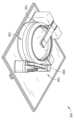
도 1은 이러한 개시 내용의 실시형태에 따른, 반도체 웨이퍼의 통합된 분해 및 스캐닝을 위한 시스템의 등각도이다.
도 2는 반도체 웨이퍼가 챔버 내에 배치된 도 1의 시스템의 등각도이다.
도 3은 스캔 아암이 노즐을 반도체 웨이퍼의 표면 위에 배치하는, 도 1의 시스템의 등각도이다.
도 4는 노즐로부터 분배된 스캐닝 유체와 함께 도시된, 도 1의 시스템의 스캔 아암의 하부측의 등각도이다.
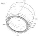
도 5는 스캐닝 유체가 없이 도시된, 도 4의 노즐의 하부측의 등각도이다.
도 6은 방향 화살표가 충진 동작 중의 스캐닝 유체의 유동을 보여 주는, 도 4의 노즐의 하부측의 등각도이다.
도 7은 방향 화살표가 회수 동작 중의 스캐닝 유체의 유동을 보여 주는, 도 4의 노즐의 하부측의 등각도이다.
도 8a는 이러한 개시 내용의 실시형태에 따른, 웨이퍼의 표면 상의 노즐의 채널을 통해서 유동하는 스캐닝 유체의 패턴의 저면 평면도이다.
도 8b는 이러한 개시 내용의 실시형태에 따른, 웨이퍼의 표면 상의 노즐의 채널을 통해서 유동하는 스캐닝 유체의 패턴의 저면 평면도이다.
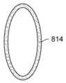
도 8c는 이러한 개시 내용의 실시형태에 따른, 웨이퍼의 표면 상의 노즐의 채널을 통해서 유동하는 스캐닝 유체의 패턴의 저면 평면도이다.
도 8d는 이러한 개시 내용의 실시형태에 따른, 웨이퍼의 표면 상의 노즐의 채널을 통해서 유동하는 스캐닝 유체의 패턴의 저면 평면도이다.
도 8e는 이러한 개시 내용의 실시형태에 따른, 웨이퍼의 표면 상의 노즐의 채널을 통해서 유동하는 스캐닝 유체의 패턴의 저면 평면도이다.
도 8f는 이러한 개시 내용의 실시형태에 따른, 웨이퍼의 표면 상의 노즐의 채널을 통해서 유동하는 스캐닝 유체의 패턴의 저면 평면도이다.
도 9는 스캔 아암이 노즐의 린스 스테이션(rinse station)에 배치된, 도 1의 시스템의 부분 등각도이다.A detailed description will be made with reference to the accompanying drawings. The same reference number may be used in different instances in the description and drawings to indicate similar or identical articles.
1 is an isometric view of a system for integrated disassembly and scanning of semiconductor wafers, according to an embodiment of the disclosure.
Figure 2 is an isometric view of the system of Figure 1 with a semiconductor wafer placed in a chamber.
Figure 3 is an isometric view of the system of Figure 1, where a scan arm positions a nozzle over the surface of a semiconductor wafer.
Figure 4 is an isometric view of the underside of the scan arm of the system of Figure 1, shown with scanning fluid dispensed from the nozzle.
Figure 5 is an isometric view of the underside of the nozzle of Figure 4, shown without scanning fluid.
Figure 6 is an isometric view of the underside of the nozzle of Figure 4, with directional arrows showing the flow of scanning fluid during a filling operation.
Figure 7 is an isometric view of the underside of the nozzle of Figure 4, with directional arrows showing the flow of scanning fluid during a recovery operation.
FIG. 8A is a bottom plan view of a pattern of scanning fluid flowing through channels of a nozzle on the surface of a wafer, according to an embodiment of the disclosure.
FIG. 8B is a bottom plan view of a pattern of scanning fluid flowing through channels of a nozzle on the surface of a wafer, according to an embodiment of the disclosure.
FIG. 8C is a bottom plan view of a pattern of scanning fluid flowing through channels of a nozzle on the surface of a wafer, according to an embodiment of the disclosure.
FIG. 8D is a bottom plan view of a pattern of scanning fluid flowing through channels of a nozzle on the surface of a wafer, according to an embodiment of the disclosure.
FIG. 8E is a bottom plan view of a pattern of scanning fluid flowing through channels of a nozzle on the surface of a wafer, according to an embodiment of the disclosure.
FIG. 8F is a bottom plan view of a pattern of scanning fluid flowing through channels of a nozzle on the surface of a wafer, according to an embodiment of the disclosure.
Figure 9 is a partial isometric view of the system of Figure 1 with the scan arm positioned at the rinse station of the nozzle.
개요outline
샘플 내의 미량 원소의 농도 또는 양을 결정하는 것은 샘플의 순도의 표시, 또는 시약, 반응 성분 등으로서의 샘플의 이용 가능성을 제공할 수 있다. 예를 들어, 특정 생산 또는 제조 프로세스(예를 들어, 광산, 야금, 반도체 제조, 의약 프로세싱 등)에서, 불순물에 대한 공차가, 예를 들어 십억분의 1의 분률 정도로, 매우 엄격할 수 있다. 반도체 웨이퍼 프로세싱에서, 캐리어 수명의 감소, 웨이퍼 구성요소의 유전체 파괴, 및 기타로 인해서 웨이퍼의 성능을 저하시킬 수 있거나 웨이퍼가 동작하지 못하게 할 수 있는 금속 불순물과 같은 불순물에 대해서 웨이퍼를 테스트한다.Determining the concentration or amount of a trace element in a sample can provide an indication of the purity of the sample or its availability as a reagent, reaction component, etc. For example, in certain production or manufacturing processes (e.g., mining, metallurgy, semiconductor manufacturing, pharmaceutical processing, etc.), tolerances for impurities may be very tight, for example on the order of parts per billion. In semiconductor wafer processing, wafers are tested for impurities such as metallic impurities that can degrade wafer performance or render it inoperable due to reduced carrier life, dielectric breakdown of wafer components, and others.
기상 분해(VPD) 및 후속하는 웨이퍼의 스캐닝은 웨이퍼의 조성을 분석하여 금속 불순물이 존재하는지의 여부를 결정하기 위한 기술이다. 통상적인 VPD 및 스캐닝 기술은 불순물 분석을 위한 규소 웨이퍼의 처리 및 스캐닝을 용이하게 하는데 있어서 처리량(throughput)이 제한되었다. 예를 들어, 시스템은 종종 VPD 절차 및 스캐닝 절차를 위한 별도의 챔버들을 이용한다. VPD 챔버에서, 표면에 존재하는 이산화규소 및 기타 금속 불순물이 증기(예를 들어, 불산(HF), 과산화수소(H2O2), 이들의 조합)와 접촉되고 증기(예를 들어, 사불화규소(SiF4))로서 표면으로부터 제거된다. 처리된 웨이퍼는 스캐닝을 위한 별도의 챔버로 운반되고, 여기에서 액적(liquid droplet)이 처리된 웨이퍼 표면에 도입되어, 분해 증기와 웨이퍼의 반응 후에 잔류물을 수집한다. 스캐닝 절차는 스캔 헤드로 액적을 웨이퍼의 표면 상에서 유지하는 것, 그리고 스캔 헤드를 이동시키면서 또는 스캔 헤드를 정지적으로 유지하면서 웨이퍼를 회전시켜 액적을 표면 위에서 이동시키는 것을 포함할 수 있다. 웨이퍼의 여러 번의 회전 후에, 액적은 웨이퍼의 희망 표면 면적과 상호 작용하여 분해 후에 임의의 잔류물을 접촉 표면으로부터 끌어 낸다. 그러나, 통상적인 웨이퍼 처리 기술은, 처리 중에 분해 챔버로부터 스캔 챔버로 그리고 린스 챔버로의 웨이퍼의 통과 이동, 스캐닝 중에 액적과 웨이퍼 표면의 상호 작용이 제한되는 스캔 노즐의 이용(즉, 액적과 전체 표면적 또는 그 일부를 상호 작용시키기 위해서 웨이퍼의 다수의 회전을 필요로 하는 것), 및 기타와 같이, 웨이퍼를 프로세스하는데 있어서 상당한 양의 시간 및 장비를 필요로 한다. 또한, 그러한 웨이퍼의 핸들링은 기술자 또는 다른 사람을 독성 불산에 잠재적으로 노출시킬 수 있거나, 웨이퍼를 다양한 프로세스 챔버들 사이에서 전달하는 동안 웨이퍼에 대한 환경 오염 위험을 증가시킬 수 있으며, 이러한 전달은 또한 장비 및 장비들 사이의 전달 메커니즘을 위한 상당한 물리적 프로세스 바닥 설치 공간을 필요로 할 수 있다.Vapor phase decomposition (VPD) and subsequent scanning of the wafer is a technique for analyzing the composition of the wafer to determine whether metallic impurities are present. Conventional VPD and scanning technologies have limited throughput in facilitating processing and scanning of silicon wafers for impurity analysis. For example, systems often utilize separate chambers for the VPD procedure and scanning procedure. In the VPD chamber, silicon dioxide and other metal impurities present on the surface are contacted with vapor (e.g., hydrofluoric acid (HF), hydrogen peroxide (H2 O2 ), combinations thereof) and vapor (e.g., silicon tetrafluoride) (SiF4 )) is removed from the surface. The processed wafer is transported to a separate chamber for scanning, where liquid droplets are introduced onto the treated wafer surface to collect residues after reaction of the wafer with the decomposition vapors. The scanning procedure may include holding a droplet on the surface of a wafer with a scan head, and moving the droplet over the surface by rotating the wafer while moving the scan head or while holding the scan head stationary. After several rotations of the wafer, the droplet interacts with the desired surface area of the wafer, pulling any residue from the contact surface after decomposition. However, conventional wafer handling techniques include the passage of the wafer from the digestion chamber to the scan chamber and into the rinse chamber during processing, and the use of scan nozzles where the interaction of the droplets with the wafer surface during scanning is limited (i.e., the droplet's overall surface area is or those that require multiple rotations of the wafer to make parts of it interact), and so on, require a significant amount of time and equipment to process the wafer. Additionally, handling of such wafers may potentially expose technicians or others to toxic hydrofluoric acid, or may increase the risk of environmental contamination to the wafers while transferring them between various process chambers, which may also increase the risk of environmental contamination to the wafers. and may require significant physical process floor footprint for transfer mechanisms between equipment.
따라서, 본 개시 내용은, 적어도 부분적으로, 반도체 웨이퍼 분해 및 스캐닝을 위한 시스템 및 방법에 관한 것이고, 여기에서 챔버는 단일 챔버 설치 공간으로 반도체 웨이퍼의 분해 및 스캐닝을 촉진하고, 노즐은, 유체의 하나 이상의 스트림을, 스트림을 웨이퍼 표면을 따라서 지향시키기 위한 하나 이상의 세장형 채널을 형성하는 노즐 후드에 의해서 안내되는 반도체 웨이퍼의 하나 이상의 표면을 따라서 지향시킨다. 세장형 채널은 직선형, 곡선형 또는 그 조합일 수 있고, 그에 따라 노즐의 충진 중에 스캔 유체의 기하형태적 구성을 제공할 수 있고, 이는 다시 스캐닝 유체를 웨이퍼의 표면을 가로질러 지향시킨다. 노즐은 스캐닝 유체를 세장형 채널 내에서, 노즐의 내측부 영역 내에서, 또는 그 조합에서 유지하기 위해서 진공이 노즐에 인가되는 것을 촉진하기 위한 하나 이상의 진공 포트를 포함할 수 있다. 구현예에서, 노즐은, 웨이퍼의 표면에의 도입을 위해서 스캐닝 유체가 통과하는 충진 포트의 위치에 대향되는 노즐의 영역 내의 세장형 채널의 적어도 하나에 의해서 형성되는 얇은 영역을 포함하고, 여기에서 얇은 영역은 회수 포트를 통한 회수 중에 유체 스트림의 제어된 회수를 촉진할 수 있다. 구현예에서, 회수 포트는 충진 포트에 인접한다. 구현예에서, 유체 스트림의 충진 및 회수가 단일 포트를 통해서 이루어진다.Accordingly, the present disclosure relates, at least in part, to systems and methods for disassembling and scanning semiconductor wafers, wherein a chamber facilitates disassembly and scanning of a semiconductor wafer in a single chamber footprint, and a nozzle is one of the fluids. The streams are directed along one or more surfaces of the semiconductor wafer guided by a nozzle hood that defines one or more elongated channels for directing the streams along the wafer surface. The elongated channels may be straight, curved, or a combination thereof, thereby providing geometric configuration of the scanning fluid during filling of the nozzle, which in turn directs the scanning fluid across the surface of the wafer. The nozzle may include one or more vacuum ports to facilitate the application of a vacuum to the nozzle to maintain the scanning fluid within the elongate channel, within the inner region of the nozzle, or a combination thereof. In an embodiment, the nozzle comprises a thin region defined by at least one of the elongated channels in the region of the nozzle opposite the location of the fill port through which the scanning fluid passes for introduction to the surface of the wafer, wherein the thin region The zone may facilitate controlled recovery of the fluid stream during recovery through the recovery port. In an embodiment, the recovery port is adjacent to the fill port. In embodiments, filling and withdrawal of the fluid stream occurs through a single port.
챔버는 챔버 내의 유체 이동을 제어하면서 분해 및 린싱하기 위한, 예를 들어 배액(draining)을 위한 그리고 교차 오염 방지를 위한 구역들을 챔버 내에 제공할 수 있다. 모터 시스템이 챔버 본체에 대한 웨이퍼 지지부의 수직 위치를 제어하여, 반도체를 챔버 본체 내에서 이동시킬 수 있게 하고(웨이퍼를 적재 및 하역하기 위해서 모터 시스템에 의해서 지지되는 챔버 본체 위에 배치할 수 있게 하고), 노즐에 대한 접근을 제공할 수 있게 하고, 기타 등등을 할 수 있게 한다. 챔버는, 웨이퍼 지지부가 반도체 웨이퍼를 챔버의 내측부 영역 내에 배치하는 동안, 분무기에 의해서 에어로졸화된 분해 유체를 반도체 웨이퍼의 표면 상으로 직접적으로 지향시키기 위해서 분무기를 더 포함할 수 있다. 챔버는 덮개를 포함할 수 있고, 덮개는 챔버에 대해서 개방 및 폐쇄되어 예를 들어 분해 프로세스 중에 챔버의 내측부 영역을 챔버 외부의 영역으로부터 격리시킬 수 있다. 노즐은 회전 가능 스캔 아암에 의해서 챔버에 대해서 배치될 수 있고, 노즐은 챔버로부터 멀리 배치되어 (예를 들어, 분해 절차 중에) 덮개 폐쇄를 돕거나 린스 스테이션에서 노즐의 린싱을 도울 수 있다. 또한, 스캔 아암은, 스캐닝 절차 중에, 예를 들어 웨이퍼 표면에 대한 노즐의 회전을 통해서 노즐을 반도체 웨이퍼 위에 배치할 수 있다. 시스템은, 블랭크(blank)의 준비를 위해서, 시스템 구성요소를 린싱하기 위해서, 그리고 기타를 위해서, 웨이퍼의 표면으로부터 유체를 노즐에 도입하는 것을 제어하기 위해서 스위칭 가능 선택기 밸브 및 펌프를 포함하는, 유체 핸들링 시스템을 이용할 수 있다. 스캐닝 절차 이후에 또는 도중에, 스캐닝 유체가 수집될 수 있고, 스캐닝 유체의 분해에 관한 분석적 결정을 위해서 분석 장치(예를 들어, ICPMS 장치)로 전달될 수 있다.The chamber may provide zones within the chamber for disassembly and rinsing, for example for draining, and to prevent cross-contamination while controlling fluid movement within the chamber. The motor system controls the vertical position of the wafer support relative to the chamber body, allowing the semiconductor to be moved within the chamber body (and placed on the chamber body supported by the motor system for loading and unloading the wafer). , to provide access to the nozzle, and so on. The chamber may further include an atomizer for directing aerosolized digestion fluid by the atomizer directly onto a surface of the semiconductor wafer while the wafer support positions the semiconductor wafer within an interior region of the chamber. The chamber can include a lid, which can be opened and closed relative to the chamber to isolate an area interior to the chamber from an area outside the chamber, for example during a digestion process. The nozzle can be positioned relative to the chamber by the rotatable scan arm, and the nozzle can be positioned away from the chamber to aid in lid closure (eg, during a disassembly procedure) or to aid rinsing of the nozzle at a rinse station. Additionally, the scan arm may position the nozzle over the semiconductor wafer during the scanning procedure, such as through rotation of the nozzle relative to the wafer surface. The system includes a switchable selector valve and a pump to control the introduction of fluid into the nozzle from the surface of the wafer for preparing blanks, rinsing system components, and other purposes. A handling system is available. After or during the scanning procedure, the scanning fluid may be collected and transferred to an analytical device (e.g., an ICPMS device) for analytical determination of the degradation of the scanning fluid.
예시적인 구현예Exemplary Implementation
도 1 내지 도 9는 이러한 개시 내용의 여러 실시형태에 따른, 반도체 웨이퍼의 통합된 분해 및 스캐닝을 위한 시스템("시스템(100)")의 양태를 도시한다. 반도체 웨이퍼를 참조하여 시스템(100)을 설명하지만, 시스템(100)은 그러한 재료로 제한되지 않고 실질적으로 평면형 표면을 갖는 재료와 같은 임의의 재료와 함께 이용될 수 있다. 시스템(100)은 일반적으로 챔버(102) 및 스캔 아암 조립체(104)를 포함하고, 이러한 스캔 아암 조립체는 분해 유체를 웨이퍼(108)에 도입하는 것을 통해서 그리고 스캐닝 유체를 웨이퍼(108)의 하나 이상의 표면에 도입하고 그로부터 제거하는 것을 통해서 적어도 반도체 웨이퍼(108)(본원에서 종종 "웨이퍼"로 지칭됨)의 분해 및 스캐닝 절차를 돕기 위한 유체 핸들링 시스템 및 모터 시스템을 지지한다. 챔버(102)는 하나의 챔버 설치 공간을 갖는 웨이퍼 분해 및 웨이퍼 스캐닝의 각각을 위한 환경을 제공하고, 웨이퍼(108)를 유지하기 위한 웨이퍼 지지부(110), 및 (예를 들어, 챔버(102) 내의, 챔버(102) 위의, 등의) 챔버(102)에 대한 웨이퍼 지지부(110)의 수직 위치를 제어하여 시스템(100)의 분해 및 스캐닝 절차를 위해서 또는 그 다른 절차 중에 웨이퍼(108)를 배치하기 위한 모터 시스템을 포함한다. 모터 시스템은 부가적으로 시스템(100)의 여러 절차 중에 웨이퍼(108)를 회전시키기 위한 웨이퍼 지지부(110)의 회전 제어를 제공하고, 스캔 아암 조립체(104)의 노즐을 (예를 들어, 도 3에 도시된) 스캐닝 절차 중에 웨이퍼(108) 위의 위치로 그리고 (예를 들어, 도 9에 도시된) 노즐 세정을 위한 린스 스테이션(114)의 위치로 가져가기 위한 스캔 아암 조립체(104)의 회전 및 수직 제어를 제공한다. 구현예에서, 웨이퍼 지지부(110)는, 예를 들어 웨이퍼 지지부(110)의 이동 중에, 웨이퍼(108)를 웨이퍼 지지부(110)에 대해서 고정적으로 유지하기 위한 진공 테이블을 포함한다.1-9 illustrate aspects of a system for integrated disassembly and scanning of semiconductor wafers (“
챔버(102)는, 프로세싱을 위해서 웨이퍼(108)를 수용하기 위한 내측부 영역(118)을 형성하는 챔버 본체(116)를 포함한다. 도 1에 도시된 예시적인 동작 중에, 시스템(100)은, 예를 들어 웨이퍼(108)를 FOUP(front end unified pod) 또는 다른 위치로부터 선택하여 선택된 웨이퍼(108)를 웨이퍼 지지부(110) 상으로 (예를 들어, 웨이퍼 지지부(110) 상에서 센터링되게) 도입하는 자동화된 아암(50)의 동작을 통해서, 반도체 웨이퍼(108)를 웨이퍼 지지부(110) 상으로 수용할 수 있다. 웨이퍼(108)를 웨이퍼 지지부(110) 상에 셋팅하기 위해서 자동화된 아암(50)이 웨이퍼 지지부(110)에 접근할 수 있게 하기 위해서, 모터 시스템은 웨이퍼 지지부(110)를 챔버 본체(122)의 상단 부분(122)에, 그 위에, 또는 그에 인접하여 배치할 수 있다. 예를 들어, 웨이퍼 지지부(110)는 웨이퍼(108)의 적재 중에 챔버(102)의 상단부에서 위치되는 개구부(126)에 인접하여 배치될 수 있다.
시스템(100)은, 분해 유체가 외측부 영역(132)에 노출되는 것을 제한하면서 웨이퍼 분해를 촉진하기 위해서, 내측부 영역(118)을 외측부 영역(132)으로부터 격리하기 위한 덮개(130)를 포함할 수 있다. 예를 들어, 덮개(130)는 개구부(126) 위에 배치될 때 개구부(126)를 덮기 위한 크기 및 형상을 가질 수 있다. 덮개(130)는 (예를 들어, 도 1에 도시된) 개방 위치와 (예를 들어, 도 2에 도시된) 폐쇄 위치 사이에서 배치될 수 있다. 개방 위치는 자동화된 아암에 접근을 제공하기 위해서 웨이퍼 적재 중에, 스캐닝 절차 중에, 웨이퍼 하역 절차 중에, 기타 중에 이용될 수 있다. 구현예에서, 덮개(130)는 웨이퍼 지지부(110)가 개구부(126)에 인접한 제1 위치에 있을 때 개방 위치에 있고, 그에 따라 웨이퍼(108)에 대한 스캔 아암 조립체(104)의 노즐의 접근을 제공한다. 폐쇄 위치는, 분해 유체가 개구부(126)를 통해서 챔버(102)를 빠져 나가는 것을 방지하기 위해서, 웨이퍼 분해 절차 중에 이용될 수 있다. 구현예에서, 덮개(130)의 적어도 일부가 챔버 본체(116)와 접촉하여 내측부 영역(118)을 외측부 영역(132)으로부터 격리시킨다. 웨이퍼(108)는 모터 시스템에 의한 웨이퍼 지지부(110)의 수직 위치의 제어를 통해서 내측부 영역(118) 내에서 제2 위치로 이동된다.
웨이퍼 지지부(110)로의 웨이퍼(108)의 도입 후에, 시스템(100)은 웨이퍼(108)의 하나 이상의 표면 또는 연부의 분해를 촉진하기 위해서 분해 구성으로 전환될 수 있다. 구현예에서, 챔버(102)는 분해 유체를 웨이퍼 지지부(110) 상의 웨이퍼(108)의 표면 상으로 분무하기 위해서 챔버 본체(116) 내에 배치된 분무기를 포함한다. 분해 유체는 분무기에 의해서 챔버(102) 내로 직접 분무될 수 있다.After introduction of
웨이퍼(108)의 분해 후에, 시스템(100)은 스캐닝 구성으로 전환되어, 웨이퍼(108)를 별도의 스캐닝 시스템으로 전달하지 않고도, 스캔 아암 조립체(104)가 웨이퍼(108)의 하나 이상의 표면에 접근하게 할 수 있다. 스캐닝 구성으로 전환하기 위해서, 모터 시스템은 웨이퍼 지지부(110)를 개구부(126)에 인접하여 또는 달리 챔버 본체(116)의 상단부에 더 가까이 배치하여, 스캔 아암 조립체(104)가 웨이퍼(108)의 표면에 접근하는 것을 허용할 수 있다. 스캔 아암 조립체(104)는 일반적으로, 스캔 유체를 웨이퍼(108)의 표면에 도입하고 스캔 유체를 웨이퍼(108)의 표면으로부터 회수하도록 구성된 노즐(304)을 지지하는 노즐 하우징(302)에 커플링된 회전 가능 아암 지지부(300)를 포함한다. 모터 시스템은 회전 가능 아암 지지부(300)의 회전, 회전 가능 아암 지지부(300)의 수직 위치, 또는 그 조합을 제어하여, 노즐 하우징(302) 및 노즐(304)을 시스템(100) 내의 다수의 위치에 걸쳐 배치할 수 있다. 예를 들어, 모터 시스템은 노즐 하우징(302) 및 노즐(304)을 (예를 들어, 도 9에 도시된) 린스 스테이션(306)에서의 하나 이상의 위치와 (예를 들어, 도 3에 도시된) 웨이퍼(108)에 인접하거나 그 위의 하나 이상의 위치 사이에서 이동시킬 수 있다. 도 4 내지 도 8f를 참조하여, 노즐(304)의 예시적인 구현예를 본원에서 더 설명한다. 구현예에서, 회전 가능 아암 지지부(300)는, 웨이퍼 지지부(110)가 챔버(102)의 상단 부분에 배치될 때, 노즐(304)을 회전시키거나 달리 이동시켜 노즐(304)을 웨이퍼(108)에 인접 배치하고, (예를 들어, 분해 중에) 웨이퍼 지지부(110)가 챔버(102)의 내측부 내에 배치될 때, 노즐(304)을 개방 위치로부터 폐쇄 위치까지 덮개(130)의 경로 외측에 배치한다.After disassembly of the
웨이퍼(108)에 인접한 또는 그 위의 노즐(304) 위치에서(예를 들어, 도 3에 도시됨), 유체 핸들링 시스템이 노즐(304)로의 그리고 그로부터의 스캐닝 유체의 도입을 제어하여 웨이퍼(108)의 표면의 스캐닝 절차를 촉진할 수 있다. 도 4 내지 도 7을 참조하면, 노즐(304)의 예시적인 구현예가 도시되어 있다. 노즐(304)은 (도 4에서 400으로 도시된) 하나 이상의 유체 스트림을 웨이퍼(108)의 표면에 걸쳐 전달하도록 구성되고, 이는 스폿-크기 액적이 웨이퍼(108) 위에서 이동하는 것보다 짧은 기간에 웨이퍼(108)의 더 넓은 표면적을 커버할 수 있다. 유체의 스트림(또는 스트림들)이 노즐(304)에 의해서 웨이퍼(108)의 표면 위에서 안내되어, 웨이퍼(108)의 희망 표면적을 제어 가능하게 스캔한다. 구현예에서, 노즐(304)은, 웨이퍼(108)의 1번의 회전으로, 유체 스트림을 웨이퍼(108)의 실질적으로 전체 표면에 걸쳐 안내한다. 구현예에서, 표면의 쐐기 형상부(wedge)(예를 들어, 웨이퍼(108)의 섹터 또는 그 일부)가 웨이퍼(108)의 1번의 회전의 일부 중에 스캐닝될 수 있다. 웨이퍼(108)의 스캐닝되는 면적은 일반적으로 노즐(304)의 형상 및 웨이퍼(108)의 회전량에 따라 달라지고, 상이한 노즐 형상들은 웨이퍼(108)의 상이한 스캐닝 패턴 또는 커버리지(coverage)를 제공할 수 있다(예를 들어, 도 8a 내지 도 8f와 관련하여 더 설명된다).At the location of the
노즐 후드(502) 및 내측부 영역(504)을 형성하는 노즐 본체(500)를 포함하는 노즐(304)이 도시되어 있고, 내측부 영역은 웨이퍼의 스캐닝을 위해서 노즐(304)에 의해서 수용된 유체의 유동을 하나 이상의 유체 포트를 통해서 지향시킨다. 제1 유체 포트(506), 제2 유체 포트(508), 및 진공 포트(510)가 예시적인 포트 구성으로 도시되어 있다. 예를 들어, 노즐(304)은 유체를 유지 라인 또는 루프(예를 들어, 샘플 유지 루프)로부터 노즐(304) 내로 미는 펌프(예를 들어, 주사기 펌프, 격막 펌프 등)의 작용을 통해서 유체를 수용하고, 여기에서 유체는 제1 유체 포트(506) 내로 그리고 노즐 후드(502)에 의해서 형성된 채널 또는 채널들을 통해서 지향된다. 예를 들어, 제1 채널(512) 및 제2 채널(514)을 형성하는 노즐 후드(502)가 도시되어 있고, 제1 유체 포트(506)를 빠져 나가는 유체의 적어도 일부가 이러한 채널들을 통해서 지향된다. 구현예에서, 제1 유체 포트(506)를 빠져 나가는 유체가 노즐 본체(500)로부터 노즐 후드(502) 내로 직접적으로 도입되어 노즐 후드(502)에 의해서 웨이퍼(108)의 표면을 따라서 안내되도록, 제1 유체 포트(506)가 노즐 후드(502) 내에서 배출구를 제공한다. 제1 채널(512) 및 제2 채널(514)이 노즐 후드(502)의 벽 또는 다른 구조물에 의해서 형성되어, 각각의 채널을 분배를 위해 유체를 수용하는 포트와 유체적으로 커플링시킬 수 있다. 예를 들어, 제1 채널(512) 및 제2 채널(514)은 노즐 후드(502)의 외측부 벽(516)과 내측부 벽(518) 사이에 형성된다.A
구현예에서, 유체는, 노즐 후드(502)에 의해서 안내되는 실질적으로 연속적인 유체 스트림으로서, 제1 노즐 포트(506)를 통해서 웨이퍼(108)의 표면 상으로 제공되고 웨이퍼(108)의 표면을 따라서 지향된다. 예를 들어, 도 6은, 유체가 웨이퍼(108)의 표면 상으로 제공될 때, 노즐 후드(502)가 유체의 제1 부분(600)을 제1 채널(512) 내로 안내하고 유체의 제2 부분(602)을 제2 채널(514) 내로 안내하는 것을 도시하고, 여기에서 유체의 제1 부분(600) 및 유체의 제2 부분(602) 내의 유체는 접착력 또는 다른 유체 특성을 통해서 연결되어 유지될 수 있다. 시스템(100)은, 채널들이 충진될 때까지, 유체의 부분들이 함께 결합될 때까지, 또는 그 조합까지, 유체의 제1 부분(600) 및 유체의 제2 부분(602)이 채널(512 및 514)을 통해서 유동하도록, 충분한 부피의 유체를 노즐(304)에 도입할 수 있다. 예를 들어, 유체의 제1 부분(600) 및 유체의 제2 부분(602)은, 유체 부분들의 전방 단부들이 노즐의 영역(520)에서 만나 (예를 들어, 도 4에 도시된) 하나의 연속적인 유체의 형상을 형성할 때까지, 제1 채널(512) 및 제2 채널(514)을 통해서 각각 유동할 수 있다. 따라서, 유체는 제1 유체 포트(506)로부터 영역(520)으로 운반되는 동안(예를 들어, 채널(512 및 514)를 따라서 운반되는 동안) 웨이퍼(108)와 접촉될 수 있다. 구현예에서, 영역(520)은, 제1 노즐 포트(506)에 대향되는, 제1 채널(512)이 제2 채널(514)과 연결되는 노즐 후드(502)의 부분에 위치된다.In an embodiment, the fluid is provided onto the surface of the
노즐(304)의 충진 및 웨이퍼(108)의 표면 상으로의 유체의 분배 중에, 유체를 웨이퍼(108)의 표면으로부터 회수하는 중에, 그리고 이들의 조합 중에, 진공이 (예를 들어, 진공 포트(510)를 통해서) 노즐 본체(500)의 내측부 영역(504)에 인가될 수 있다. 진공은 유체에서 장력을 유지하는데 도움을 줄 수 있고, 이는 (예를 들어, 유체가 웨이퍼(108)의 표면을 횡단할 때 유체 스트림 내에서 간극을 방지함으로써 또는 유체 스트림 내에서 중단부를 방지함으로써) 연속적인 유체 스트림을 유지하는데 도움을 줄 수 있다. 대안적으로 또는 부가적으로, 진공은 임의의 과다 유체를 채널(512 및 514)로부터 노즐 본체의 내측부 영역(504) 내로 전환하여, 제어되지 않은 유체가 노즐 후드(502)를 빠져 나가는 것 그리고 노즐(304)의 제어를 벗어나 웨이퍼(108)의 지역 상으로 유출되는 것(예를 들어, 측방향으로 외측부 벽(516)을 지나서 유출되는 것)을 방지할 수 있다. 따라서, 스캐닝 동작 중에, 노즐이 웨이퍼(108) 위의 위치에 있게 되면, 스캔 유체가 노즐(304)로부터 충진 포트를 통해서 노즐 후드(502) 내의 웨이퍼 표면(108) 상으로 도입될 수 있고, 채널(512 및 514) 주위로 지향되어 충진 포트에 대향되는 영역(520)에서 만날 수 있다. 웨이퍼(108)는 스캐닝 동작 중에 회전될 수 있고, 노즐 하우징(302)은 회전 가능 아암 지지부(300)의 작용을 통해서 노즐(304)을 웨이퍼(108)에 대해서 회전시킬 수 있다. 충분한 유체가 도입되어 노즐 후드(502)를 충진한 경우, 과다 유체는 내측부 영역(504) 내로 유동할 수 있다.During filling of
스캐닝 절차 중에 또는 이후에, 웨이퍼(108)에 도입된 유체는 노즐(304)을 통해서 웨이퍼(108)의 표면으로부터 제거될 수 있다. 예를 들어, 유체는, 유체를 노즐의 유체 포트를 통해서 끌어 당기는 펌프(예를 들어, 주사기 펌프, 격막 펌프 등)의 작용을 통해서 표면(146)으로부터 제거될 수 있다. 구현예에서, 유체는 제2 유체 포트(508)를 통해서 끌어 당겨 지고, 여기에서 유체 스트림은, (예를 들어, 도 7에 도시된 바와 같이) 유체를 제1 채널(512) 및 제2 채널(514)의 각각을 통해서 역으로 끌어 당겨 제2 유체 포트(508)를 향해서 역으로 유동시키기 위해서, 영역(520)에서 2개의 유체 부분으로 분리된다. 노즐은 노즐 후드(502)의 내측부 벽(518) 내의 개구부(522), 노즐 후드(502)의 좁은 부분(524)(예를 들어, 제1 채널(512) 및 제2 채널(514)에 비해서 좁은 횡단면), 또는 이들의 조합을 포함할 수 있고, 그에 따라 회수 중에 유체 스트림을 제1 유체 부분(600) 및 제2 유체 부분(602)으로 분리하기 위한 지역을 제공할 수 있다. 내측부 영역(504) 내에 존재할 수 있는 과다 유체는, 예를 들어 노즐 후드(502)의 내측부 벽(518) 내의 개구부(522)를 통해서 제1 채널(512) 또는 제2 채널(514)에 진입하는 것에 의해서, 회수 포트로 지향되도록 노즐 후드(502) 내로 역으로 끌어 당겨 진다.During or after the scanning procedure, fluid introduced into
구현예에서, 노즐(304)은 제1 채널(512), 제2 채널(514), 및 영역(520) 중 하나 이상에 비해서 더 넓은 횡단면을 갖는 유체 회수 포트(예를 들어, 제2 유체 포트(508))에 인접한 영역(526)을 포함하고, 그에 따라 (예를 들어, 회수 포트에서 유체 스트림의 중단을 방지함으로써) 유체 양수(uptake)를 돕기 위한 유체의 부피를 회수 포트에서 제공한다. 노즐(304)이 예에서 하나의 진공 포트 및 2개의 유체 포트를 갖는 예시적인 구현예로 도시되어 있지만, 개시 내용은 그러한 구성으로 제한되지 않고, 진공 포트를 포함하지 않을 수 있거나, 하나 초과의 진공 포트를 포함할 수 있거나, 하나의 유체 포트를 포함할 수 있거나(예를 들어, 유체 도입 및 유체 제거가 동일 포트를 통해서 이루어 진다), 2개 초과의 유체 포트를 포함할 수 있거나, 기타 등등이 이루어 질 수 있다.In an embodiment,
제1 채널(512) 및 제2 채널(514)은, 노즐 후드(502)의 도움을 받아, 소정 부피의 유체가 웨이퍼(108)에 걸쳐 이동할 수 있게 한다. 구현예에서, 노즐 후드(502)는 약 50 μL 내지 약 5,000 μL의 부피를 갖는다. 그러나, 노즐 후드(502)의 부피는 이러한 범위로 제한되지 않고, 50 μL 미만의 부피 및 5,000 μL 초과의 부피를 포함할 수 있다. 예를 들어, 채널(512 및 514)의 부피는, 희망하는 양의 유체(예를 들어, 스캐닝 유체)를 웨이퍼(108)의 표면에 제공하기 위해서 시스템(100)에 의해서 프로세스되는 웨이퍼(108)의 크기에 따라 달라질 수 있다. 구현예에서, 노즐 후드(502)는 약 100 μL 내지 약 500 μL의 유체의 부피를 웨이퍼(108) 상에서 지지한다. 노즐(304)의 치수는 시스템(100)에 의해서 프로세스되는 웨이퍼(108)의 크기를 기초로 선택될 수 있고, 구현예에서, 노즐(304)은 웨이퍼(108)의 직경과 대략적으로 유사한 폭을 갖는다. 구현예에서, 노즐(304)의 길이는 약 20 mm 내지 약 500 mm일 수 있다. 구현예에서, 노즐(304)은 웨이퍼(108)의 반경과 대략적으로 유사한 폭을 가지고, 노즐에 대한 웨이퍼(108)의 회전은 노즐 후드(502)에 의해서 지지되는 노즐(304)로부터의 유체의 커버리지를 제공한다.
노즐(304)은 하나의 일체형 단편으로부터 형성될 수 있거나, 노즐(304)의 부분들이 별도로 형성되고 융합되거나 달리 함께 커플링될 수 있다. 구현예에서, 노즐(304)은 클로로트리플루오로에틸렌(CTFE), 폴리테트라플루오로에틸렌(PTFE), 또는 이들의 조합으로 형성된다.
노즐(304)에 의해서 웨이퍼(108) 상에서 유지되는 유체 스트림을 위한 실질적으로 둥근 유동 경로를 형성하는 노즐 후드(502)를 갖는 노즐(304)을 설명하였지만, 본 개시 내용은 실질적으로 둥근 유체 스트림 경로로 제한되지 않는다. 예를 들어, 노즐(304)은, 비제한적으로, 하나 이상의 선형 유체 스트림 경로를 갖는 둥근 유체 스트림 경로, 원형 유체 스트림 경로, 타원형 유체 스트림 경로, 선형 유체 스트림 경로, 불규칙한 유체 스트림 경로, 정사각형 유체 스트림 경로, 직사각형 유체 스트림 경로, 및 이들의 조합을 포함할 수 있다. 예를 들어, 도 8a는 둥근 부분(800), 둥근 부분(800)과 교차하는 제1 선형 부분(802), 그리고 둥근 부분(800) 및 제1 선형 부분(802)의 각각과 교차하는 제2 선형 부분(804)을 갖는 노즐(304)에 의해서 형성된 유체 스트림 경로를 도시한다. 다른 예로서, 도 8b는 둥근 부분(806), 둥근 부분(806)과 교차하는 제1 선형 부분(808), 둥근 부분(806)과 교차하는 제2 선형 부분(810), 그리고 둥근 부분(806)과 교차하는 제3 선형 부분(812)을 갖는 노즐(304)에 의해서 형성된 유체 스트림 경로를 도시한다. 다른 예로서, 도 8c는 타원형 부분(814)을 갖는 노즐(304)에 의해서 형성된 유체 스트림 경로를 도시한다. 다른 예로서, 도 8d는 정사각형 부분(816)을 갖는 노즐(304)에 의해서 형성된 유체 스트림 경로를 도시한다. 다른 예로서, 도 8e는 직사각형 부분(818), 직사각형 부분(818)과 교차하는 제1 선형 부분(820), 그리고 직사각형 부분(818) 및 제1 선형 부분(820)의 각각과 교차하는 제2 선형 부분(822)을 갖는 노즐(304)에 의해서 형성된 유체 스트림 경로를 도시한다. 다른 예로서, 도 8f는 직사각형 부분(824)을 갖는 노즐(304)에 의해서 형성된 유체 스트림 경로를 도시한다.Although the
내재된 또는 외부적으로 시스템(100)을 구동하는 제어 로직을 통한 자동화된 동작을 돕기 위해서, 전기기계적 장치(예를 들어, 전기 모터, 서보, 작동기, 또는 기타)가 시스템(100)의 구성요소와 커플링될 수 있거나 그 내부에 내재될 수 있다. 전기기계 장치는 본원에서 설명된 절차와 같은 여러 절차에 따라 장치 및 유체를 이동시키도록 구성될 수 있다. 시스템(100)은 비-일시적 캐리어 매체(non-transitory carrier medium)(예를 들어, 플래시 드라이브, 하드 디스크 드라이브, 솔리드-스테이트 디스크 드라이브, SD 카드, 또는 광학적 디스크, 등과 같은 저장 매체)로부터의 컴퓨터 판독 가능 프로그램 명령어(즉, 제어 로직)를 실행하도록 구성된 프로세서 또는 다른 제어기를 가지는 컴퓨팅 시스템을 포함하거나 그에 의해서 제어될 수 있다. 컴퓨팅 시스템은, 직접 연결에 의해서 또는 하나 이상의 네트워크 연결(예를 들어, 근거리 통신망(LAN), 무선 지역 통신망(WAN 또는 WLAN), 하나 이상의 허브 연결(예를 들어, USB 허브) 등)을 통해서, 시스템(100)의 여러 구성요소에 연결될 수 있다. 예를 들어, 컴퓨팅 시스템은 챔버(102), 모터 시스템, 본원에 설명된 밸브, 본원에 설명된 펌프, 본원에 설명된 다른 구성요소, 그 제어를 지시하는 구성요소 또는 이들의 조합에 통신적으로 커플링될 수 있다. 프로그램 명령어는, 프로세서 또는 다른 제어기에 의해서 실행될 때, 컴퓨팅 시스템이, 본원에서 설명된 바와 같은, 하나 이상의 동작 모드에 따라 시스템(100)(예를 들어, 제어 펌프, 선택 밸브, 작동기, 분무 노즐, 배치 장치 등)을 제어)하게 할 수 있다.Electromechanical devices (e.g., electric motors, servos, actuators, or other) may be incorporated into components of
본 개시 내용 전반을 통해서 설명된 여러 기능, 제어 동작, 프로세싱 블록, 또는 단계가 하드웨어, 소프트웨어 또는 펌웨어의 임의 조합에 의해서 실행될 수 있다는 것을 이해하여야 한다. 일부 실시형태에서, 여러 단계 또는 기능이 이하 중 하나 이상에 의해서 실행된다: 전자 회로망, 로직 게이트, 멀티플렉서, 프로그래밍 가능 로직 장치, 주문형 집적 회로(ASIC), 제어기/마이크로제어기, 또는 컴퓨팅 시스템. 컴퓨팅 시스템은, 비제한적으로, 개인용 컴퓨팅 시스템, 모바일 컴퓨팅 장치, 메인프레임 컴퓨팅 시스템, 워크스테이션, 이미지 컴퓨터, 병렬 프로세서, 또는 당업계에 공지된 임의의 다른 장치를 포함할 수 있다. 일반적으로, "컴퓨팅 시스템"이라는 용어는 캐리어 매체로부터 명령어를 실행하는 하나 이상의 프로세서 또는 다른 제어기를 갖는 임의의 장치를 포함하도록 광범위하게 규정될 수도 있다.It should be understood that the various functions, control operations, processing blocks, or steps described throughout this disclosure may be implemented by any combination of hardware, software, or firmware. In some embodiments, the various steps or functions are performed by one or more of the following: electronic circuitry, logic gates, multiplexers, programmable logic devices, application specific integrated circuits (ASICs), controllers/microcontrollers, or computing systems. Computing systems may include, but are not limited to, personal computing systems, mobile computing devices, mainframe computing systems, workstations, imaging computers, parallel processors, or any other devices known in the art. In general, the term “computing system” may be broadly defined to include any device having one or more processors or other controllers that execute instructions from a carrier medium.
본원에서 설명된 실시형태에 의해서 명백해진 것과 같은, 기능, 제어 동작, 프로세싱 블록, 또는 단계를 구현하는 프로그램 명령어는 캐리어 매체를 통해서 전달되거나 그에 저장될 수 있다. 캐리어 매체는, 비제한적으로, 와이어, 케이블, 또는 무선 송신 링크와 같은 송신 매체일 수 있다. 캐리어 매체는 또한, 비제한적으로, 리드-온리 메모리, 랜덤 액세스 메모리, 자기 또는 광학 디스크, 솔리드-스테이트 또는 플래시 메모리 장치, 또는 자기 테이프와 같은 비-일시적 신호 보유 매체 또는 저장 매체를 포함할 수 있다.Program instructions implementing functions, control operations, processing blocks, or steps, such as those made apparent by the embodiments described herein, may be transmitted over or stored on a carrier medium. The carrier medium may be a transmission medium such as, but not limited to, a wire, cable, or wireless transmission link. Carrier media may also include, but are not limited to, non-transitory signal retention or storage media such as read-only memory, random access memory, magnetic or optical disks, solid-state or flash memory devices, or magnetic tape. .
또한, 본 발명이 첨부된 청구범위에 의해서 규정된다는 것을 이해할 수 있을 것이다. 비록 본 발명의 실시형태가 예시되었지만, 개시 내용의 범위 및 사상으로부터 벗어나지 않고도, 다양한 수정이 당업자에 의해서 이루어질 수 있다는 것이 명백하다.It will also be understood that the present invention is defined by the appended claims. Although embodiments of the invention have been illustrated, it will be apparent that various modifications may be made by those skilled in the art without departing from the scope and spirit of the disclosure.
Claims (20)
Translated fromKorean상기 노즐을 재료 표면에 대해서 배치하기 위한 배치 가능 노즐 아암 지지부에 커플링되도록 구성된 노즐 본체로서, 유체를 상기 노즐 내로 수용하기 위한 적어도 하나의 유체 포트를 형성하는, 노즐 본체; 및
상기 노즐 본체에 커플링된 노즐 후드로서, 상기 노즐 후드는 상기 적어도 하나의 유체 포트로부터 연장되는 적어도 제1 유체 채널 및 제2 유체 채널을 갖는 세장형의 성형 채널을 형성하고, 상기 제1 유체 채널 및 제2 유체 채널은 상기 제1 유체 채널 및 제2 유체 채널의 각각의 적어도 일부 내에서 유체를 상기 재료 표면을 따라서 지향시키도록 구성되는, 노즐 후드를 포함하는, 노즐.A nozzle for scanning the surface of a material with a fluid:
a nozzle body configured to be coupled to a deployable nozzle arm support for positioning the nozzle relative to a material surface, the nozzle body defining at least one fluid port for receiving fluid into the nozzle; and
A nozzle hood coupled to the nozzle body, the nozzle hood forming an elongated shaped channel having at least a first fluid channel and a second fluid channel extending from the at least one fluid port, the first fluid channel and a nozzle hood, wherein the second fluid channel is configured to direct fluid along the material surface within at least a portion of each of the first fluid channel and the second fluid channel.
상기 적어도 하나의 세장형의 성형 채널은 상기 노즐의 충진 동작 중에 상기 유체를 적어도 하나의 기하형태적 구성 내로 지향시키는, 노즐.According to paragraph 1,
and wherein the at least one elongated forming channel directs the fluid into at least one geometric configuration during a filling operation of the nozzle.
상기 기하형태적 구성이 직사각형 구성을 포함하는, 노즐.According to paragraph 2,
A nozzle, wherein the geometrical configuration includes a rectangular configuration.
상기 기하형태적 구성이 둥근 구성을 포함하는, 노즐.According to paragraph 2,
A nozzle, wherein the geometric configuration includes a round configuration.
상기 제1 유체 채널 및 제2 유체 채널의 적어도 하나가 곡선형 채널인, 노즐.According to paragraph 1,
A nozzle, wherein at least one of the first fluid channel and the second fluid channel is a curved channel.
상기 적어도 하나의 세장형의 성형 채널은 상기 곡선형 채널의 일부와 교차하는 적어도 하나의 직선형 채널을 더 포함하는, 노즐.According to clause 5,
The nozzle of claim 1, wherein the at least one elongated shaped channel further comprises at least one straight channel that intersects a portion of the curved channel.
상기 제1 유체 채널 및 제2 유체 채널의 적어도 하나가 직선형 채널인, 노즐.According to paragraph 1,
A nozzle, wherein at least one of the first fluid channel and the second fluid channel is a straight channel.
상기 적어도 하나의 세장형의 성형 채널은 상기 직선형 채널의 일부와 교차하는 적어도 하나의 부가적인 직선형 채널을 더 포함하는, 노즐.In clause 7,
The nozzle of claim 1, wherein the at least one elongated shaped channel further comprises at least one additional straight channel that intersects a portion of the straight channel.
상기 노즐 본체는, 범람 유체를 상기 적어도 하나의 세장형의 성형 채널로부터 내측부 영역 내로 끌어 들이기 위해서 진공과 커플링되도록 구성된 진공 포트를 갖는 내측부 영역을 형성하는, 노즐.According to paragraph 1,
and the nozzle body defines an inner region having a vacuum port configured to couple with a vacuum to draw flooding fluid from the at least one elongated forming channel into the inner region.
상기 노즐을 재료 표면에 대해서 배치하기 위한 배치 가능 노즐 아암 지지부에 커플링되도록 구성된 노즐 본체로서, 유체를 상기 노즐 내로 수용하도록 구성된 유체 포트를 형성하고 진공 공급원과 커플링되도록 구성된 진공 포트를 갖는 내측부 영역을 형성하는, 노즐 본체; 및
상기 노즐 본체에 커플링된 노즐 후드로서, 상기 노즐 후드는 외측부 벽 및 내측부 벽을 포함하고, 외측부 벽 및 내측부 벽은 외측부 벽과 내측부 벽 사이에 위치되며 상기 유체 포트와 유체 연통되는 제1 유체 채널 및 제2 유체 채널을 형성하고, 상기 내측부 벽은 상기 내측부 영역의 적어도 일부를 경계 짓고, 상기 유체 포트의 배출구가 상기 외측부 벽과 상기 내측부 벽 사이에 배치되어 상기 진공 공급원에 의한 진공 포트에 대한 진공의 적용 중에 유체를 상기 유체 포트로부터 상기 제1 유체 채널 및 제2 유체 채널의 각각의 적어도 일부 내로 도입하여 상기 유체를 상기 제1 유체 채널 및 제2 유체 채널의 각각의 일부 내에서 상기 재료 표면을 따라 지향시키는, 노즐 후드를 포함하는, 노즐.A nozzle for scanning the surface of a material with a fluid:
a nozzle body configured to be coupled to a deployable nozzle arm support for positioning the nozzle relative to a material surface, the inner portion defining a fluid port configured to receive fluid into the nozzle and having a vacuum port configured to couple to a vacuum source. forming a nozzle body; and
A nozzle hood coupled to the nozzle body, the nozzle hood comprising an outer wall and an inner wall, the outer wall and the inner wall being positioned between the outer wall and the inner wall and a first fluid channel in fluid communication with the fluid port. and forming a second fluid channel, wherein the inner wall bounds at least a portion of the inner region, and wherein the outlet of the fluid port is disposed between the outer wall and the inner wall to provide vacuum to the vacuum port by the vacuum source. During application of a fluid is introduced from the fluid port into at least a portion of each of the first fluid channel and the second fluid channel to direct the fluid to the material surface within each portion of the first fluid channel and the second fluid channel. A nozzle, including a nozzle hood, for directing along.
상기 내측부 벽은 상기 유체 포트에 대향되는 상기 노즐 후드의 영역에서 개구부를 포함하고, 상기 개구부는 상기 내측부 영역 내로의 유체 접근을 제공하는, 노즐.According to clause 10,
wherein the inner wall includes an opening in a region of the nozzle hood opposite the fluid port, the opening providing fluid access into the inner region.
상기 제1 유체 채널 및 제2 유체 채널의 적어도 하나는 상기 유체 포트에 대향되는 상기 노즐 후드의 영역에서 좁은 부분을 가지는, 노즐.According to clause 10,
and wherein at least one of the first fluid channel and the second fluid channel has a narrow portion in an area of the nozzle hood opposite the fluid port.
상기 내측부 벽은 상기 유체 포트에 대향되는 상기 노즐 후드의 영역에서 개구부를 포함하고, 상기 개구부는 상기 내측부 영역 내로의 유체 접근을 제공하는, 노즐.According to clause 12,
wherein the inner wall includes an opening in a region of the nozzle hood opposite the fluid port, the opening providing fluid access into the inner region.
상기 노즐 본체는 상기 노즐 후드와 유체 연통되는 제2 유체 포트를 형성하고, 제2 유체 포트는 유체를 상기 노즐 후드로부터 제거하도록 구성되는, 노즐.According to clause 10,
The nozzle body defines a second fluid port in fluid communication with the nozzle hood, and the second fluid port is configured to remove fluid from the nozzle hood.
상기 제2 유체 포트가 상기 유체 포트에 인접하는, 노즐.According to clause 14,
The nozzle, wherein the second fluid port is adjacent the fluid port.
상기 제1 유체 채널 또는 제2 유체 채널의 적어도 하나는, 상기 제1 유체 채널 또는 제2 유체 채널의 적어도 하나의 나머지보다 더 넓은 면적을 갖는 유체 포트에 인접한 영역을 형성하는, 노즐.According to clause 10,
and wherein at least one of the first or second fluid channels defines an area adjacent the fluid port having a larger area than the remainder of the at least one of the first or second fluid channels.
노즐을 통해서 스캔 유체를 재료의 표면에 도입하는 단계로서, 상기 노즐은
노즐을 재료 표면에 대해서 배치하기 위한 배치 가능 노즐 아암 지지부에 커플링되도록 구성된 노즐 본체로서, 유체를 노즐 내로 수용하도록 구성된 유체 포트를 형성하고 진공 공급원과 커플링되도록 구성된 진공 포트를 갖는 내측부 영역을 형성하는, 노즐 본체, 및
상기 노즐 본체에 커플링된 노즐 후드로서, 상기 노즐 후드는 외측부 벽 및 내측부 벽을 포함하고, 외측부 벽 및 내측부 벽은 외측부 벽과 내측부 벽 사이에 위치되며 상기 유체 포트와 유체 연통되는 제1 유체 채널 및 제2 유체 채널을 형성하고, 상기 내측부 벽은 상기 내측부 영역의 적어도 일부를 경계 짓고, 상기 유체 포트의 배출구가 상기 외측부 벽과 상기 내측부 벽 사이에 배치되어 진공 공급원에 의한 진공 포트에 대한 진공의 적용 중에 유체를 상기 유체 포트로부터 상기 제1 유체 채널 및 제2 유체 채널의 각각의 적어도 일부 내로 도입하여 상기 유체를 상기 제1 유체 채널 및 제2 유체 채널의 각각의 일부 내에서 상기 재료 표면을 따라 지향시키는, 노즐 후드를 포함하는, 단계;
상기 노즐을 통해서, 상기 스캔 유체를 상기 재료의 표면을 따라서 지향시키는 단계로서, 상기 유체의 적어도 일부는 상기 제1 유체 채널 및 제2 유체 채널의 각각에서 유지되는, 단계;
상기 제1 유체 채널 및 제2 유체 채널로부터의 상기 스캔 유체를 상기 유체 포트와 구분되는 상기 노즐 후드의 영역에서 함께 결합하는 단계; 및
상기 노즐을 통해서 상기 스캔 유체를 상기 재료 표면으로부터 제거하는 단계를 포함하는, 방법.A method for scanning the surface of a material with a molded nozzle:
Introducing a scanning fluid to the surface of a material through a nozzle, wherein the nozzle
A nozzle body configured to be coupled to a deployable nozzle arm support for positioning the nozzle relative to a material surface, the nozzle body defining a fluid port configured to receive fluid into the nozzle and defining an interior region having a vacuum port configured to couple to a vacuum source. a nozzle body, and
A nozzle hood coupled to the nozzle body, the nozzle hood comprising an outer wall and an inner wall, the outer wall and the inner wall being positioned between the outer wall and the inner wall and a first fluid channel in fluid communication with the fluid port. and forming a second fluid channel, wherein the medial wall bounds at least a portion of the medial region, and wherein the outlet of the fluid port is disposed between the outer wall and the medial wall, so as to provide a vacuum to the vacuum port by a vacuum source. During application, fluid is introduced from the fluid port into at least a portion of each of the first and second fluid channels to force the fluid along the material surface within each portion of the first and second fluid channels. directing, comprising a nozzle hood;
directing, through the nozzle, the scan fluid along a surface of the material, wherein at least a portion of the fluid is retained in each of the first and second fluid channels;
combining the scan fluid from the first fluid channel and the second fluid channel together in a region of the nozzle hood distinct from the fluid port; and
Removing the scan fluid from the material surface through the nozzle.
상기 내측부 벽은 상기 유체 포트에 대향되는 상기 노즐 후드의 영역에서 개구부를 포함하고, 상기 개구부는 상기 내측부 영역 내로의 유체 접근을 제공하는, 방법.According to clause 17,
The method of claim 1, wherein the inner wall includes an opening in a region of the nozzle hood opposite the fluid port, the opening providing fluid access into the inner region.
상기 제1 유체 채널 및 제2 유체 채널의 적어도 하나는 상기 유체 포트에 대향되는 상기 노즐 후드의 영역에서 좁은 부분을 가지는, 방법.According to clause 17,
wherein at least one of the first fluid channel and the second fluid channel has a narrow portion in an area of the nozzle hood opposite the fluid port.
상기 노즐을 통해서 스캔 유체를 재료의 표면으로부터 제거하는 단계는, 상기 후드 내에 배치된 유체 포트 또는 제2 유체 포트 중 적어도 하나를 경유하여, 상기 스캔 유체를 상기 재료의 표면으로부터 상기 노즐을 통해서 제거하는 단계를 포함하는, 방법.According to clause 17,
Removing the scanning fluid from the surface of the material through the nozzle includes removing the scanning fluid from the surface of the material through the nozzle via at least one of a fluid port or a second fluid port disposed within the hood. A method comprising steps.
Applications Claiming Priority (3)
| Application Number | Priority Date | Filing Date | Title |
|---|---|---|---|
| US202163137873P | 2021-01-15 | 2021-01-15 | |
| US63/137,873 | 2021-01-15 | ||
| PCT/US2022/011425WO2022155044A1 (en) | 2021-01-15 | 2022-01-06 | Shaped-channel scanning nozzle for scanning of a material surface |
Publications (1)
| Publication Number | Publication Date |
|---|---|
| KR20230130648Atrue KR20230130648A (en) | 2023-09-12 |
Family
ID=82406484
Family Applications (1)
| Application Number | Title | Priority Date | Filing Date |
|---|---|---|---|
| KR1020237023650APendingKR20230130648A (en) | 2021-01-15 | 2022-01-06 | Form-channel scanning nozzle for scanning material surfaces |
Country Status (5)
| Country | Link |
|---|---|
| US (2) | US12300480B2 (en) |
| JP (1) | JP2024504641A (en) |
| KR (1) | KR20230130648A (en) |
| TW (1) | TW202242951A (en) |
| WO (1) | WO2022155044A1 (en) |
Families Citing this family (3)
| Publication number | Priority date | Publication date | Assignee | Title |
|---|---|---|---|---|
| US11705351B2 (en) | 2017-12-01 | 2023-07-18 | Elemental Scientific, Inc. | Systems for integrated decomposition and scanning of a semiconducting wafer |
| EP4136670A4 (en)* | 2020-04-16 | 2024-04-17 | Elemental Scientific, Inc. | Systems for integrated decomposition and scanning of a semiconducting wafer |
| WO2025049474A1 (en)* | 2023-09-01 | 2025-03-06 | Elemental Scientific, Inc. | Systems and methods for recovering organic contaminants from semiconducting wafers |
Family Cites Families (7)
| Publication number | Priority date | Publication date | Assignee | Title |
|---|---|---|---|---|
| JP4369325B2 (en)* | 2003-12-26 | 2009-11-18 | 東京エレクトロン株式会社 | Development device and development processing method |
| US7448741B2 (en) | 2004-04-30 | 2008-11-11 | Fujifilm Dimatix, Inc. | Elongated filter assembly |
| US8387635B2 (en)* | 2006-07-07 | 2013-03-05 | Tel Fsi, Inc. | Barrier structure and nozzle device for use in tools used to process microelectronic workpieces with one or more treatment fluids |
| JP5031542B2 (en)* | 2007-12-26 | 2012-09-19 | 東京エレクトロン株式会社 | Two-fluid nozzle, substrate cleaning apparatus and substrate cleaning method |
| KR101909984B1 (en)* | 2017-11-30 | 2018-10-19 | 주식회사 쓰리디프리욜 | Nozzle for cleaning substrate |
| US11705351B2 (en)* | 2017-12-01 | 2023-07-18 | Elemental Scientific, Inc. | Systems for integrated decomposition and scanning of a semiconducting wafer |
| CN109378289A (en)* | 2018-11-29 | 2019-02-22 | 杭州众硅电子科技有限公司 | A kind of system and method for rinsing with dry wafer |
- 2022
- 2022-01-06KRKR1020237023650Apatent/KR20230130648A/enactivePending
- 2022-01-06USUS17/569,936patent/US12300480B2/enactiveActive
- 2022-01-06WOPCT/US2022/011425patent/WO2022155044A1/ennot_activeCeased
- 2022-01-06JPJP2023542903Apatent/JP2024504641A/enactivePending
- 2022-01-14TWTW111101590Apatent/TW202242951A/enunknown
- 2025
- 2025-04-18USUS19/183,185patent/US20250299941A1/enactivePending
Also Published As
| Publication number | Publication date |
|---|---|
| US20250299941A1 (en) | 2025-09-25 |
| TW202242951A (en) | 2022-11-01 |
| WO2022155044A1 (en) | 2022-07-21 |
| US12300480B2 (en) | 2025-05-13 |
| US20220230864A1 (en) | 2022-07-21 |
| JP2024504641A (en) | 2024-02-01 |
Similar Documents
| Publication | Publication Date | Title |
|---|---|---|
| JP7534510B2 (en) | System for integrated decomposition and scanning of semiconductor wafers. | |
| KR20230130648A (en) | Form-channel scanning nozzle for scanning material surfaces | |
| US20250189412A1 (en) | Systems for integrated decomposition and scanning of a semiconducting wafer |
Legal Events
| Date | Code | Title | Description |
|---|---|---|---|
| PA0105 | International application | Patent event date:20230712 Patent event code:PA01051R01D Comment text:International Patent Application | |
| PG1501 | Laying open of application | ||
| A201 | Request for examination | ||
| PA0201 | Request for examination | Patent event code:PA02012R01D Patent event date:20241224 Comment text:Request for Examination of Application |