KR20230122878A - Washing machine - Google Patents
Washing machineDownload PDFInfo
- Publication number
- KR20230122878A KR20230122878AKR1020220019660AKR20220019660AKR20230122878AKR 20230122878 AKR20230122878 AKR 20230122878AKR 1020220019660 AKR1020220019660 AKR 1020220019660AKR 20220019660 AKR20220019660 AKR 20220019660AKR 20230122878 AKR20230122878 AKR 20230122878A
- Authority
- KR
- South Korea
- Prior art keywords
- sensor
- bumper
- robot cleaner
- detection device
- case
- Prior art date
- Legal status (The legal status is an assumption and is not a legal conclusion. Google has not performed a legal analysis and makes no representation as to the accuracy of the status listed.)
- Pending
Links
Images


Classifications
- A—HUMAN NECESSITIES
- A47—FURNITURE; DOMESTIC ARTICLES OR APPLIANCES; COFFEE MILLS; SPICE MILLS; SUCTION CLEANERS IN GENERAL
- A47L—DOMESTIC WASHING OR CLEANING; SUCTION CLEANERS IN GENERAL
- A47L9/00—Details or accessories of suction cleaners, e.g. mechanical means for controlling the suction or for effecting pulsating action; Storing devices specially adapted to suction cleaners or parts thereof; Carrying-vehicles specially adapted for suction cleaners
- A47L9/28—Installation of the electric equipment, e.g. adaptation or attachment to the suction cleaner; Controlling suction cleaners by electric means
- A47L9/2889—Safety or protection devices or systems, e.g. for prevention of motor over-heating or for protection of the user
- A—HUMAN NECESSITIES
- A47—FURNITURE; DOMESTIC ARTICLES OR APPLIANCES; COFFEE MILLS; SPICE MILLS; SUCTION CLEANERS IN GENERAL
- A47L—DOMESTIC WASHING OR CLEANING; SUCTION CLEANERS IN GENERAL
- A47L9/00—Details or accessories of suction cleaners, e.g. mechanical means for controlling the suction or for effecting pulsating action; Storing devices specially adapted to suction cleaners or parts thereof; Carrying-vehicles specially adapted for suction cleaners
- A47L9/28—Installation of the electric equipment, e.g. adaptation or attachment to the suction cleaner; Controlling suction cleaners by electric means
- A—HUMAN NECESSITIES
- A47—FURNITURE; DOMESTIC ARTICLES OR APPLIANCES; COFFEE MILLS; SPICE MILLS; SUCTION CLEANERS IN GENERAL
- A47L—DOMESTIC WASHING OR CLEANING; SUCTION CLEANERS IN GENERAL
- A47L11/00—Machines for cleaning floors, carpets, furniture, walls, or wall coverings
- A47L11/40—Parts or details of machines not provided for in groups A47L11/02 - A47L11/38, or not restricted to one of these groups, e.g. handles, arrangements of switches, skirts, buffers, levers
- A47L11/4011—Regulation of the cleaning machine by electric means; Control systems and remote control systems therefor
- A—HUMAN NECESSITIES
- A47—FURNITURE; DOMESTIC ARTICLES OR APPLIANCES; COFFEE MILLS; SPICE MILLS; SUCTION CLEANERS IN GENERAL
- A47L—DOMESTIC WASHING OR CLEANING; SUCTION CLEANERS IN GENERAL
- A47L9/00—Details or accessories of suction cleaners, e.g. mechanical means for controlling the suction or for effecting pulsating action; Storing devices specially adapted to suction cleaners or parts thereof; Carrying-vehicles specially adapted for suction cleaners
- A47L9/009—Carrying-vehicles; Arrangements of trollies or wheels; Means for avoiding mechanical obstacles
- A—HUMAN NECESSITIES
- A47—FURNITURE; DOMESTIC ARTICLES OR APPLIANCES; COFFEE MILLS; SPICE MILLS; SUCTION CLEANERS IN GENERAL
- A47L—DOMESTIC WASHING OR CLEANING; SUCTION CLEANERS IN GENERAL
- A47L9/00—Details or accessories of suction cleaners, e.g. mechanical means for controlling the suction or for effecting pulsating action; Storing devices specially adapted to suction cleaners or parts thereof; Carrying-vehicles specially adapted for suction cleaners
- A47L9/28—Installation of the electric equipment, e.g. adaptation or attachment to the suction cleaner; Controlling suction cleaners by electric means
- A47L9/2805—Parameters or conditions being sensed
- A—HUMAN NECESSITIES
- A47—FURNITURE; DOMESTIC ARTICLES OR APPLIANCES; COFFEE MILLS; SPICE MILLS; SUCTION CLEANERS IN GENERAL
- A47L—DOMESTIC WASHING OR CLEANING; SUCTION CLEANERS IN GENERAL
- A47L9/00—Details or accessories of suction cleaners, e.g. mechanical means for controlling the suction or for effecting pulsating action; Storing devices specially adapted to suction cleaners or parts thereof; Carrying-vehicles specially adapted for suction cleaners
- A47L9/28—Installation of the electric equipment, e.g. adaptation or attachment to the suction cleaner; Controlling suction cleaners by electric means
- A47L9/2836—Installation of the electric equipment, e.g. adaptation or attachment to the suction cleaner; Controlling suction cleaners by electric means characterised by the parts which are controlled
- A47L9/2852—Elements for displacement of the vacuum cleaner or the accessories therefor, e.g. wheels, casters or nozzles
- B—PERFORMING OPERATIONS; TRANSPORTING
- B25—HAND TOOLS; PORTABLE POWER-DRIVEN TOOLS; MANIPULATORS
- B25J—MANIPULATORS; CHAMBERS PROVIDED WITH MANIPULATION DEVICES
- B25J19/00—Accessories fitted to manipulators, e.g. for monitoring, for viewing; Safety devices combined with or specially adapted for use in connection with manipulators
- B25J19/0091—Shock absorbers
- B—PERFORMING OPERATIONS; TRANSPORTING
- B25—HAND TOOLS; PORTABLE POWER-DRIVEN TOOLS; MANIPULATORS
- B25J—MANIPULATORS; CHAMBERS PROVIDED WITH MANIPULATION DEVICES
- B25J19/00—Accessories fitted to manipulators, e.g. for monitoring, for viewing; Safety devices combined with or specially adapted for use in connection with manipulators
- B25J19/02—Sensing devices
- B—PERFORMING OPERATIONS; TRANSPORTING
- B25—HAND TOOLS; PORTABLE POWER-DRIVEN TOOLS; MANIPULATORS
- B25J—MANIPULATORS; CHAMBERS PROVIDED WITH MANIPULATION DEVICES
- B25J19/00—Accessories fitted to manipulators, e.g. for monitoring, for viewing; Safety devices combined with or specially adapted for use in connection with manipulators
- B25J19/06—Safety devices
- B25J19/063—Safety devices working only upon contact with an outside object
- B—PERFORMING OPERATIONS; TRANSPORTING
- B25—HAND TOOLS; PORTABLE POWER-DRIVEN TOOLS; MANIPULATORS
- B25J—MANIPULATORS; CHAMBERS PROVIDED WITH MANIPULATION DEVICES
- B25J9/00—Programme-controlled manipulators
- B25J9/0003—Home robots, i.e. small robots for domestic use
- B—PERFORMING OPERATIONS; TRANSPORTING
- B25—HAND TOOLS; PORTABLE POWER-DRIVEN TOOLS; MANIPULATORS
- B25J—MANIPULATORS; CHAMBERS PROVIDED WITH MANIPULATION DEVICES
- B25J9/00—Programme-controlled manipulators
- B25J9/16—Programme controls
- B25J9/1674—Programme controls characterised by safety, monitoring, diagnostic
- B25J9/1676—Avoiding collision or forbidden zones
- G—PHYSICS
- G05—CONTROLLING; REGULATING
- G05D—SYSTEMS FOR CONTROLLING OR REGULATING NON-ELECTRIC VARIABLES
- G05D1/00—Control of position, course, altitude or attitude of land, water, air or space vehicles, e.g. using automatic pilots
- G05D1/02—Control of position or course in two dimensions
- G05D1/021—Control of position or course in two dimensions specially adapted to land vehicles
- G05D1/0212—Control of position or course in two dimensions specially adapted to land vehicles with means for defining a desired trajectory
- G05D1/0214—Control of position or course in two dimensions specially adapted to land vehicles with means for defining a desired trajectory in accordance with safety or protection criteria, e.g. avoiding hazardous areas
- G—PHYSICS
- G05—CONTROLLING; REGULATING
- G05D—SYSTEMS FOR CONTROLLING OR REGULATING NON-ELECTRIC VARIABLES
- G05D1/00—Control of position, course, altitude or attitude of land, water, air or space vehicles, e.g. using automatic pilots
- G05D1/20—Control system inputs
- G05D1/24—Arrangements for determining position or orientation
- G05D1/241—Means for detecting physical contact, e.g. touch sensors or bump sensors
- A—HUMAN NECESSITIES
- A47—FURNITURE; DOMESTIC ARTICLES OR APPLIANCES; COFFEE MILLS; SPICE MILLS; SUCTION CLEANERS IN GENERAL
- A47L—DOMESTIC WASHING OR CLEANING; SUCTION CLEANERS IN GENERAL
- A47L2201/00—Robotic cleaning machines, i.e. with automatic control of the travelling movement or the cleaning operation
- A47L2201/04—Automatic control of the travelling movement; Automatic obstacle detection
- G—PHYSICS
- G05—CONTROLLING; REGULATING
- G05D—SYSTEMS FOR CONTROLLING OR REGULATING NON-ELECTRIC VARIABLES
- G05D2105/00—Specific applications of the controlled vehicles
- G05D2105/10—Specific applications of the controlled vehicles for cleaning, vacuuming or polishing
- G—PHYSICS
- G05—CONTROLLING; REGULATING
- G05D—SYSTEMS FOR CONTROLLING OR REGULATING NON-ELECTRIC VARIABLES
- G05D2109/00—Types of controlled vehicles
- G05D2109/10—Land vehicles
Landscapes
- Engineering & Computer Science (AREA)
- Mechanical Engineering (AREA)
- Robotics (AREA)
- Aviation & Aerospace Engineering (AREA)
- Radar, Positioning & Navigation (AREA)
- Remote Sensing (AREA)
- Physics & Mathematics (AREA)
- General Physics & Mathematics (AREA)
- Automation & Control Theory (AREA)
- Control Of Position, Course, Altitude, Or Attitude Of Moving Bodies (AREA)
Abstract
Description
Translated fromKorean개시된 발명은 로봇청소기에 관한 것으로, 보다 상세하게는 센서의 충돌을 감지하는 센서충돌 감지장치를 포함하는 로봇청소기에 관한 것이다.The disclosed invention relates to a robot cleaner, and more particularly, to a robot cleaner including a sensor collision detection device for detecting a collision of sensors.
로봇청소기는 사용자의 조작 없이 청소 영역을 주행하면서 바닥에 쌓인 먼지 등을 청소하는 장치이다. 로봇청소기는 구동장치를 제어하여 청소 영역을 빠짐없이 청소하고 클리닝 장치를 제어하여 먼지 등을 효율적으로 제거할 수 있다.A robot vacuum cleaner is a device that cleans dust and the like accumulated on the floor while traveling in a cleaning area without user manipulation. The robot cleaner can clean the cleaning area without omission by controlling the driving device and efficiently remove dust and the like by controlling the cleaning device.
일반적으로 로봇청소기는 각종 센서 등을 통해 청소 영역 내에 설치된 가구, 사무용품, 벽과 같은 장애물까지의 거리를 검출하고, 검출된 정보를 이용하여 청소구역을 매핑(mapping)하거나 구동부 제어를 통한 장애물 회피 등의 동작모션을 수행한다.In general, robot cleaners detect the distance to obstacles such as furniture, office supplies, and walls installed in the cleaning area through various sensors, etc., and use the detected information to map the cleaning area or avoid obstacles through driving unit control. perform the motion of
로봇청소기의 이동 거리를 예측하고, 이를 기반으로 장애물까지의 거리를 산출, 인식하는 방식을 이용한다. 최근에는 천장 또는 바닥을 주시하는 센서를 장착하고, 이를 기반으로 장애물까지의 거리를 예측 및 주행하는 청소로봇이 많아 지고 있다. 더해서 이러한 기반 기술을 이용하는 다양한 센서 유닛(Lidar)이 개발 및 제공되고 있다.A method of predicting the moving distance of the robot cleaner and calculating and recognizing the distance to the obstacle based on this is used. Recently, more and more cleaning robots are equipped with sensors that observe the ceiling or the floor, and based on these sensors, predict the distance to an obstacle and travel. In addition, various sensor units (Lidar) using these base technologies are being developed and provided.
천장 또는 바닥을 주시하는 센서를 통해 로봇청소기가 이동한 거리를 계측하고, 이를 기반으로 장애물까지의 거리를 산출하는 방식은 바닥의 굴곡 등으로 로봇청소기의 이동 거리가 정확하게 계측되지 못하는 경우 장애물과의 충돌이 발생하고, 장착된 센서의 오차를 유발하는 문제가 있다.The method of measuring the distance the robot cleaner has moved through a sensor that looks at the ceiling or the floor and calculating the distance to the obstacle based on this is a method in which the moving distance of the robot cleaner cannot be accurately measured due to the curvature of the floor, etc. There is a problem in which a collision occurs and an error of the installed sensor is caused.
개시된 발명의 일 측면은, 센서충돌 감지장치를 포함하는 로봇청소기를 제공한다.One aspect of the disclosed invention provides a robot cleaner including a sensor collision detection device.
개시된 발명의 일 측면은, 장애물 회피를 능동적으로 작동할 수 있는 로봇청소기를 제공한다.One aspect of the disclosed invention provides a robot cleaner capable of actively operating obstacle avoidance.
개시된 발명의 일 측면은 다양한 형태의 센서에 적용 가능한 센서충돌 감지장치를 포함하는 로봇청소기를 제공한다.One aspect of the disclosed invention provides a robot cleaner including a sensor collision detection device applicable to various types of sensors.
개시된 발명의 일 측면은, 주행 중 센서에 충돌하는 장애물을 감지하여 장애물의 상황을 명확하게 판단할 수 잇는 로봇청소기를 제공한다.One aspect of the disclosed invention provides a robot cleaner capable of clearly determining the situation of an obstacle by detecting an obstacle colliding with a sensor while driving.
개시된 발명의 일 측면에 의한 로봇청소기는, 청소구역을 주행하며 청소하는 청소기본체; 상기 청소기본체에 마련되고, 상기 청소구역 내의 장애물을 감지하는 센서를 커버하도록 마련되는 센서 케이스; 및 상기 센서에 가해지는 충격을 감지하도록 마련되는 센서충돌 감지장치;를 포함하고, 상기 센서충돌 감지장치는, 상기 센서 케이스에 이동 가능하게 연결되고, 적어도 일부가 상기 센서의 외측 둘레에 대응되도록 마련되는 범퍼와, 상기 센서 케이스의 충돌을 감지하도록 상기 범퍼와 연동하는 감지부를 포함하며, 상기 범퍼와 상기 감지부는 상기 센서의 하측에 배치된다.A robot cleaner according to an aspect of the disclosed invention includes a cleaner main body that cleans while driving in a cleaning area; a sensor case provided in the cleaning main body and provided to cover a sensor that detects an obstacle in the cleaning area; and a sensor collision detecting device provided to detect an impact applied to the sensor, wherein the sensor collision detecting device is movably connected to the sensor case, and at least a part thereof is provided to correspond to an outer circumference of the sensor and a sensing unit interlocking with the bumper to detect a collision of the sensor case, wherein the bumper and the sensing unit are disposed below the sensor.
상기 센서충돌 감지장치는, 상기 센서를 지지하도록 마련되는 센서 홀더를 더 포함하고, 상기 범퍼와 상기 감지부는 상기 센서 홀더의 저면에 배치된다.The sensor collision detecting device further includes a sensor holder provided to support the sensor, and the bumper and the sensing unit are disposed on a lower surface of the sensor holder.
상기 범퍼와 상기 감지부는 상기 센서 홀더의 하부에 동일 선상에 배치된다.The bumper and the sensing unit are disposed on the same line under the sensor holder.
상기 센서충돌 감지장치는, 상기 센서 케이스와 장애물의 충돌 시, 상기 센서 케이스와 상기 범퍼가 연동될 수 있도록 연결하는 링크부재를 더 포함하고, 상기 링크부재는 상기 센서 케이스의 원주 방향으로 이격되어 배치되는 적어도 하나의 링크를 포함한다.The sensor collision detecting device further includes a link member connecting the sensor case and the bumper so that they can interlock when the sensor case collides with an obstacle, and the link member is spaced apart from each other in a circumferential direction of the sensor case. contains at least one link that is
상기 센서충돌 감지장치는, 상기 범퍼가 연결되도록 상기 링크에 마련되는 범퍼 연결부와, 상기 범퍼 연결부에 대응되도록 상기 범퍼에 마련되는 링크 연결부를 더 포함한다.The sensor collision detecting device further includes a bumper connecting portion provided on the link to connect the bumper, and a link connecting portion provided on the bumper to correspond to the bumper connecting portion.
상기 센서충돌 감지장치는, 상기 범퍼를 원래 위치로 복원 가능하도록 텐션을 제공하는 탄성부재를 더 포함한다.The sensor collision detection device further includes an elastic member providing tension so that the bumper can be restored to its original position.
상기 감지부는, 상기 범퍼의 적어도 일부와 접촉 가능하도록 소정 각도로 이격되게 서로 마주보게 마련되고, 대향면에 각각 서로 접촉 가능한 제1단자와 제2단자를 가지는 한 쌍의 제1스위치 및 제2스위치를 포함한다.The sensing unit is provided to face each other spaced apart at a predetermined angle so as to be in contact with at least a portion of the bumper, and a pair of first and second switches having first terminals and second terminals contactable to each other on opposite surfaces, respectively. includes
상기 범퍼는, 상기 센서 케이스의 외측 둘레에 대응되도록 형성되는 범퍼 바디와, 상기 범퍼 바디의 적어도 일부로서, 상기 제1스위치 및 제2스위치 사이에 배치되고, 각각의 상기 제2단자를 가압하여 상기 제1단자에 접촉하도록 마련되는 접촉부를 포함한다.The bumper is a bumper body formed to correspond to the outer circumference of the sensor case, and is at least a part of the bumper body and is disposed between the first switch and the second switch, and presses each of the second terminals to A contact portion provided to contact the first terminal is included.
상기 센서충돌 감지장치는, 상기 범퍼가 상기 센서 홀더에 이동 가능하게 결합되도록 마련되는 고정부재를 더 포함하고, 상기 고정부재는 상기 범퍼가 안착되는 제1고정부재와, 상기 제1고정부재를 상기 센서 홀더에 고정시키는 제2고정부재를 포함한다.The sensor collision detecting device further includes a fixing member provided so that the bumper is movably coupled to the sensor holder, the fixing member includes a first fixing member on which the bumper is seated, and the first fixing member. A second fixing member fixed to the sensor holder is included.
상기 범퍼와 상기 센서 홀더의 하면 사이에 간극(G)이 마련된다.A gap G is provided between the lower surface of the bumper and the sensor holder.
상기 센서 홀더는, 상기 고정부재가 결합되도록 상기 센서 홀더의 하면에 마련되는 결합부를 더 포함하고, 상기 결합부는 상기 범퍼와 상기 제1고정부재가 결합되도록 마련되는 결합돌기와, 상기 제2고정부재가 결합되도록 상기 결합돌기에 형성되는 결합홈을 포함한다.The sensor holder further includes a coupling portion provided on a lower surface of the sensor holder to couple the fixing member, wherein the coupling portion includes a coupling protrusion provided to couple the bumper and the first fixing member, and the second fixing member. It includes a coupling groove formed on the coupling protrusion to be coupled.
상기 범퍼는, 상기 고정부재가 결합되도록 상기 결합부에 대응되게 마련되는 결합홀을 더 포함하고, 상기 결합홀은 타원 형상으로 형성된다.The bumper further includes a coupling hole provided to correspond to the coupling portion so that the fixing member is coupled, and the coupling hole is formed in an elliptical shape.
상기 센서 홀더는, 상기 탄성부재가 결합되도록 상기 센서 홀더의 하면에 마련되는 탄성부재 설치부를 더 포함한다.The sensor holder further includes an elastic member installation portion provided on a lower surface of the sensor holder so that the elastic member is coupled thereto.
상기 범퍼는, 상기 탄성부재가 지지되도록 상기 탄성부재 설치부와 이격되어 마련되는 탄성부재 지지부를 더 포함한다.The bumper further includes an elastic member support portion provided to be spaced apart from the elastic member installation portion to support the elastic member.
개시된 발명의 일 측면에 의한 로봇청소기는, 청소구역을 주행하며 청소하는 청소기본체; 상기 청소기본체에 마련되고, 상기 청소구역 내의 장애물을 감지하는 센서를 커버하도록 마련되는 센서 케이스; 및 상기 센서에 가해지는 충격을 감지하도록 마련되는 센서충돌 감지장치;를 포함하고, 상기 센서충돌 감지장치는, 상기 센서 케이스의 내측에서 상기 센서를 지지하도록 마련되는 센서 홀더와, 상기 센서 케이스에 상대이동 가능하게 연결되고, 적어도 일부가 상기 센서의 외측 둘레와 대응되도록 마련되는 범퍼와, 상기 센서 케이스의 충돌을 감지하도록 상기 범퍼와 연동하는 감지부를 포함하며, 상기 범퍼와 상기 감지부는 상기 센서 홀더의 하부에 배치된다.A robot cleaner according to an aspect of the disclosed invention includes a cleaner main body that cleans while driving in a cleaning area; a sensor case provided in the cleaning main body and provided to cover a sensor that detects an obstacle in the cleaning area; and a sensor collision detecting device provided to detect an impact applied to the sensor, wherein the sensor collision detecting device includes a sensor holder provided to support the sensor inside the sensor case, and a sensor relative to the sensor case. A bumper movably connected and provided such that at least a portion thereof corresponds to an outer circumference of the sensor, and a sensing unit interlocking with the bumper to detect a collision of the sensor case, wherein the bumper and the sensing unit are connected to the sensor holder. placed at the bottom
상기 센서충돌 감지장치는, 상기 센서 케이스와 장애물의 충돌 시, 상기 센서 케이스와 상기 범퍼가 연동될 수 있도록 연결하는 링크부재를 더 포함하고, 상기 링크부재는 상기 센서 케이스의 원주 방향으로 이격되어 배치되는 적어도 하나의 링크를 포함한다.The sensor collision detecting device further includes a link member connecting the sensor case and the bumper so that they can interlock when the sensor case collides with an obstacle, and the link member is spaced apart from each other in a circumferential direction of the sensor case. contains at least one link that is
상기 센서충돌 감지장치는, 상기 범퍼가 연결되도록 상기 링크에 마련되는 범퍼 연결부와, 상기 범퍼 연결부에 대응되도록 상기 범퍼에 마련되는 링크 연결부를 더 포함한다.The sensor collision detecting device further includes a bumper connecting portion provided on the link to connect the bumper, and a link connecting portion provided on the bumper to correspond to the bumper connecting portion.
상기 센서충돌 감지장치는, 상기 범퍼를 원래 위치로 복원 가능하도록 텐션을 제공하는 탄성부재를 더 포함한다.The sensor collision detection device further includes an elastic member providing tension so that the bumper can be restored to its original position.
상기 감지부는, 상기 범퍼의 적어도 일부와 접촉 가능하도록 소정 각도로 이격되게 서로 마주보게 마련되고, 대향면에 각각 서로 접촉 가능한 제1단자와 제2단자를 가지는 한 쌍의 제1스위치 및 제2스위치를 포함한다.The sensing unit is provided to face each other spaced apart at a predetermined angle so as to be in contact with at least a portion of the bumper, and a pair of first and second switches having first terminals and second terminals contactable to each other on opposite surfaces, respectively. includes
상기 범퍼는, 상기 센서 케이스의 외측 둘레에 대응되도록 형성되는 범퍼 바디와, 상기 범퍼 바디의 적어도 일부로서, 상기 제1스위치 및 제2스위치 사이에 배치되고, 각각의 상기 제2단자를 가압하여 상기 제1단자에 접촉하도록 마련되는 접촉부와, 상기 탄성부재가 지지되도록 상기 탄성부재 설치부와 이격되어 마련되는 탄성부재 지지부를 포함한다.The bumper is a bumper body formed to correspond to the outer circumference of the sensor case, and is at least a part of the bumper body and is disposed between the first switch and the second switch, and presses each of the second terminals to It includes a contact portion provided to contact the first terminal, and an elastic member support portion provided to be spaced apart from the elastic member installation portion to support the elastic member.
개시된 발명의 일 측면에 따르면 센서충돌 감지장치를 포함하는 로봇청소기를 제공한다.According to one aspect of the disclosed invention, a robot cleaner including a sensor collision detection device is provided.
개시된 발명의 일 측면은, 장애물 회피를 능동적으로 작동할 수 있는 로봇청소기를 제공한다.One aspect of the disclosed invention provides a robot cleaner capable of actively operating obstacle avoidance.
개시된 발명의 일 측면은 다양한 형태의 센서에 적용 가능한 충돌감지장치를 포함하는 로봇청소기를 제공한다.One aspect of the disclosed invention provides a robot cleaner including a collision detection device applicable to various types of sensors.
도 1 은 일 실시예에 따른 로봇청소기를 개략적으로 도시한 사시도이다.
도 2 는 도 1에 도시된 로봇청소기의 저면을 나타내는 사시도이다.
도 3 은 도 1에 도시된 로봇청소기의 센서유닛을 분해하여 도시한 도면이다.
도 4 는 도 3 의 센서유닛을 측면에서 본 측면도이다.
도 5 는 일 실시예에 따른 센서충돌 감지장치가 장착된 센서유닛을 나타내는 사시도이다.
도 6 은 도 5 에 도시된 센서충돌 감지장치가 장착된 센서유닛을 나타내는 분해 사시도이다.
도 7 은 도 5 에 도시된 센서충돌 감지장치가 장착된 센서유닛을 저면에서 나타내는 분해 사시도이다.
도 8 은 도 5 에 도시된 센서유닛의 센서충돌 감지장치의 A-A'부분의 단면도이다.
도 9 는 일 실시예에 따른 센서충돌 감지장치를 나타내는 부분 사시 단면도이다.
도 10 는 도 8 의 B 부분의 확대도이다.
도 11 은 일 실시예에 따른 센서충돌 감지장치의 동작 전 상태를 나타내는 도면이다.
도 12 는 일 실시예에 따른 센서유닛의 정면 충돌 시 센서충돌 감지장치의 상태를 나타내는 도면이다.
도 13 은 일 실시예에 따른 센서유닛의 좌측 충돌 시 센서충돌 감지장치의 상태를 나타내는 도면이다.
도 14 는 일 실시예에 따른 센서유닛의 우측 충돌 시 센서충돌 감지장치의 상태를 나타내는 도면이다.
도 15 는 일 실시예에 따른 센서충돌 감지장치가 장착된 센서유닛을 나타내는 사시도이다.
도 16 은 도 15 에 도시된 센서충돌 감지장치가 장착된 센서유닛을 나타내는 분해 사시도이다.
도 17 은 도 15 에 도시된 센서충돌 감지장치가 장착된 센서유닛을 저면에서 나타내는 분해 사시도이다.
도 18 은 도 15 에 도시된 센서충돌 감지장치의 B-B'부분의 단면도이다.
도 19 는 도시된 센서충돌 감지장치가 장착된 센서유닛을 나타내는 도면이다.
도 20 은 도 15 에 도시된 센서충돌 감지장치의 감지부를 개략적으로 나타내는 부분 단면도이다.
도 21 은 도 15에 도시된 센서충돌 감지장치의 C - C' 부분의 단면도이다.1 is a perspective view schematically illustrating a robot cleaner according to an embodiment.
FIG. 2 is a perspective view showing the bottom of the robot cleaner shown in FIG. 1;
FIG. 3 is an exploded view showing the sensor unit of the robot cleaner shown in FIG. 1;
4 is a side view of the sensor unit of FIG. 3 viewed from the side;
5 is a perspective view illustrating a sensor unit equipped with a sensor collision detection device according to an exemplary embodiment;
6 is an exploded perspective view showing a sensor unit equipped with a sensor collision detecting device shown in FIG. 5;
FIG. 7 is an exploded perspective view showing a sensor unit equipped with a sensor collision detection device shown in FIG. 5 from the bottom.
FIG. 8 is a cross-sectional view of part A-A' of the sensor collision detection device of the sensor unit shown in FIG. 5;
9 is a partial perspective cross-sectional view illustrating a sensor collision detection device according to an exemplary embodiment.
Fig. 10 is an enlarged view of part B of Fig. 8;
11 is a diagram illustrating a state prior to operation of a sensor collision detection device according to an exemplary embodiment.
12 is a diagram illustrating a state of a sensor collision detecting device in case of a frontal collision of a sensor unit according to an exemplary embodiment.
13 is a diagram illustrating a state of a sensor collision detecting device when a sensor unit collides with a left side according to an exemplary embodiment.
14 is a diagram illustrating a state of a sensor collision detection device when a right side collision of a sensor unit occurs according to an exemplary embodiment.
15 is a perspective view illustrating a sensor unit equipped with a sensor collision detection device according to an exemplary embodiment.
16 is an exploded perspective view illustrating a sensor unit equipped with a sensor collision detecting device shown in FIG. 15;
FIG. 17 is an exploded perspective view showing a sensor unit equipped with a sensor collision detection device shown in FIG. 15 from the bottom.
FIG. 18 is a cross-sectional view of a BB′ portion of the sensor collision detecting device shown in FIG. 15 .
19 is a view showing a sensor unit equipped with the illustrated sensor collision detecting device.
FIG. 20 is a partial cross-sectional view schematically illustrating a sensing unit of the sensor collision detecting device shown in FIG. 15 .
FIG. 21 is a cross-sectional view of part C-C' of the sensor collision detecting device shown in FIG. 15;
본 명세서에 기재된 실시예와 도면에 도시된 구성은 개시된 발명의 바람직한 일 예에 불과할 뿐이며, 본 출원의 출원시점에 있어서 본 명세서의 실시예와 도면을 대체할 수 있는 다양한 변형 예들이 있을 수 있다.The embodiments described in this specification and the configurations shown in the drawings are only one preferred example of the disclosed invention, and there may be various modifications that can replace the embodiments and drawings in this specification at the time of filing of the present application.
또한, 본 명세서의 각 도면에서 제시된 동일한 참조번호 또는 부호는 실질적으로 동일한 기능을 수행하는 부품 또는 구성요소를 나타낸다.In addition, the same reference numerals or numerals presented in each drawing in this specification indicate parts or components that perform substantially the same function.
또한, 본 명세서에서 사용한 용어는 실시예를 설명하기 위해 사용된 것으로, 개시된 발명을 제한 및/또는 한정하려는 의도가 아니다. 단수의 표현은 문맥상 명백하게 다르게 뜻하지 않는 한, 복수의 표현을 포함한다. 본 명세서에서, "포함하다" 또는 "가지다"등의 용어는 명세서상에 기재된 특징, 숫자, 단계, 동작, 구성요소, 부품 또는 이들을 조합한 것이 존재함을 지정하려는 것이지, 하나 또는 그 이상의 다른 특징들이나 숫자, 단계, 동작, 구성요소, 부품 또는 이들을 조합한 것들의 존재 또는 부가 가능성을 미리 배제하지 않는다.In addition, terms used in this specification are used to describe embodiments, and are not intended to limit and/or limit the disclosed invention. Singular expressions include plural expressions unless the context clearly dictates otherwise. In this specification, terms such as "comprise" or "having" are intended to indicate that there is a feature, number, step, operation, component, part, or combination thereof described in the specification, but one or more other features It does not preclude in advance the existence or addition of numbers, steps, operations, components, parts, or combinations thereof.
또한, 본 명세서에서 사용한 "제1", "제2" 등과 같이 서수를 포함하는 용어는 다양한 구성요소들을 설명하는데 사용될 수 있지만, 상기 구성요소들은 상기 용어들에 의해 한정되지는 않으며, 상기 용어들은 하나의 구성요소를 다른 구성요소로부터 구별하는 목적으로만 사용된다. 예를 들어, 본 발명의 권리 범위를 벗어나지 않으면서 제1 구성요소는 제2 구성요소로 명명될 수 있고, 유사하게 제2 구성요소도 제1 구성요소로 명명될 수 있다. "및/또는"이라는 용어는 복수의 관련된 기재된 항목들의 조합 또는 복수의 관련된 기재된 항목들 중의 어느 항목을 포함한다.In addition, terms including ordinal numbers such as “first” and “second” used herein may be used to describe various components, but the components are not limited by the terms, and the terms It is used only for the purpose of distinguishing one component from another. For example, a first element may be termed a second element, and similarly, a second element may be termed a first element, without departing from the scope of the present invention. The term “and/or” includes any combination of a plurality of related listed items or any of a plurality of related listed items.
한편, 하기의 설명에서 사용된 용어 "전방", "후방", "좌측" 및 "우측"등은 도면을 기준으로 정의한 것이며, 이 용어에 의하여 각 구성요소의 형상 및 위치가 제한되는 것은 아니다.Meanwhile, the terms "front", "rear", "left", and "right" used in the following description are defined based on the drawings, and the shape and location of each component are not limited by these terms.
이하에서는 실시예를 첨부된 도면을 참조하여 상세히 설명한다.Hereinafter, an embodiment will be described in detail with reference to the accompanying drawings.
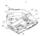
도 1 은 일 실시예에 따른 로봇청소기를 개략적으로 도시한 사시도이고, 도 2 는 도 1에 도시된 로봇청소기의 저면을 나타내는 사시도이며, 도 3 은 도 1에 도시된 로봇청소기의 센서유닛을 분해하여 도시한 도면이다.1 is a perspective view schematically showing a robot cleaner according to an embodiment, FIG. 2 is a perspective view showing a bottom of the robot cleaner shown in FIG. 1, and FIG. 3 is a disassembled sensor unit of the robot cleaner shown in FIG. 1 It is a drawing shown by
도 1 내지 도 3 에 개시된 바와 같이, 로봇청소기(1)는 청소구역을 주행하며 청소를 수행하는 청소기본체(10)와 센서유닛(100)을 포함한다.As disclosed in FIGS. 1 to 3 , the
청소기본체(10)는 흡입력을 생성하며 청소구역의 먼지를 흡입하도록 마련되는 제1케이스(11)와, 제1케이스(11)의 상부를 커버하도록 마련되는 제2케이스(12)를 포함한다.The cleaning
제1케이스(11)는 청소구역을 주행하기 위해 마련되는 휠(20), 청소구역의 먼지를 흡입하는 집진부(30), 그리고 센서유닛(100)이 설치되도록 마련되는 센서 설치부(13)를 포함할 수 있다. 제1케이스(11)는 청소구역의 먼지를 흡입하기 위한 흡입력을 생성하는 모터(미도시)를 더 포함할 수 있다.The
휠(20)은 청소구역을 이동하기 위한 2개의 메인 휠(21)을 포함할 수 있다. 휠(20)은 청소기본체(10)의 안정적인 주행을 위한 적어도 하나의 보조 휠(22)을 더 포함할 수 있다.The
집진부(30)는 흡입력에 의해 청소구역 내의 먼지를 청소기본체(10) 내로 수거할 수 있다.The
제2케이스(12)는 제1케이스(11)의 상측에 결합될 수 있다. 제2케이스(12)는 제1케이스(11)와 결합하여 내측에 모터 등이 장착될 수 있다.The
제1케이스(11)와 제2케이스(12)에는 센서유닛(100)이 설치되기 위한 센서 설치부(13)가 마련될 수 있다. 실시예에서 센서설치부는 제1케이스와 제2케이스에 의해 마련되는 것을 예를 들어 도시하였으나, 본 발명의 사상은 이에 한정되지 않는다. 예를 들어 센서설치부는 제1케이스 및/또는 제2케이스에 각각 마련될 수 있다.A
센서유닛(100)은 청소기본체(10)의 센서 설치부(13)에 수용될 수 있다. 센서유닛(100)은 장애물의 위치나 장애물과의 거리 등을 감지할 수 있도록 마련된다.The
센서유닛(100)은 센서 설치부(13) 내에 설치될 수 있다. 센서유닛(100)은 로봇청소기(1)가 청소를 위해 주행하는 상태에서 장애물의 위치나 장애물과의 거리 등을 감지하도록 마련된다.The
센서유닛(100)은 청소기본체(10)로부터 상향 돌출되어 마련될 수 있다. 센서유닛(100)은 제1케이스(11)로부터 상측으로 돌출되어 마련될 수 있다. 센서유닛(100)은 청소기본체(10)의 상면으로부터 돌출된 상태로 마련될 수 있다. 센서유닛(100)은 센서충돌 감지장치(200)에 의해 충돌을 감지할 수 있다. 일 실시예에서 로봇청소기의 주행상태에서 장애물 감지 동작을 하기 위해 센서유닛은 로봇청소기의 청소기본체로부터 상향 돌출되어 마련되는 것을 예를 들어 도시하였으나, 본 발명의 사상은 이에 한정되지 않는다. 예를 들어 센서유닛은 청소기본체로부터 상하로 승하강 이동 가능하거나 또는 회전 또는 수평 이동될 수 있도록 구성될 수도 있다.The
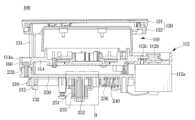
도 4 는 도 3 의 센서유닛을 측면에서 본 측면도이고, 도 5 는 일 실시예에 따른 센서충돌 감지장치가 장착된 센서유닛을 나타내는 사시도이며, 도 6 은 도 5 에 도시된 센서충돌 감지장치가 장착된 센서유닛을 나타내는 분해 사시도이고, 도 7 은 도 5 에 도시된 센서충돌 감지장치가 장착된 센서유닛을 저면에서 나타내는 분해 사시도이다. 이하에서, 상기한 설명과 중복되는 부분에 대한 설명은 생략한다.4 is a side view of the sensor unit of FIG. 3 viewed from the side, FIG. 5 is a perspective view showing a sensor unit equipped with a sensor collision detection device according to an embodiment, and FIG. 6 is a sensor collision detection device shown in FIG. 5 It is an exploded perspective view showing the mounted sensor unit, and FIG. 7 is an exploded perspective view showing the sensor unit to which the sensor collision detection device shown in FIG. 5 is mounted from the bottom. Hereinafter, descriptions of overlapping parts with the above descriptions will be omitted.
도 4 내지 도 7 에 도시된 바와 같이, 로봇청소기(1)는 센서유닛(100), 센서충돌 감지장치(200)를 포함할 수 있다.As shown in FIGS. 4 to 7 , the
센서유닛(100)은 센서(110)와, 센서(110)를 커버하도록 마련되는 센서 케이스(120)을 포함할 수 있다.The
센서(110)는 청소구역에 적외선 광, 레이저 광 또는 초음파를 조사하고 장애물에 부딪혀 반사하는 적외선 광 등을 이용하여 장애물과의 거리, 장애물의 위치 등을 감지할 수 있다. 도시되지는 않았지만, 센서(110)는 광을 방출하는 광원 및 방출된 광이 장애물에 부딪혀 반사는 광을 받는 이미지 수신부를 포함할 수 있다. 광원은 적외선이나 가시광선을 발광시키는 발광체, 예를 들어 적외선 또는 가시광선 발광 다이오드(LED) 또는 레이저 광을 출사하는 발광체를 포함할 수 있다. 이미지 수신부는 매트릭스 형태로 배열된 복수개의 단위 픽셀들의 집합체로서, 각 단위 픽셀들은 Cds(cadmium sulfide cell, 황화카드뮴셀), 광 다이오드(PHOTO DIODE), 광 트랜지스터(PHOTO TRANSISTOR) 등의 다양한 수광소자로 구현될 수 있다.The
센서(110)는 원통형으로 형성될 수 있다. 센서(110)는 광을 방출하고 방출된 광이 장애물에 부딪혀 되돌아오는 광을 수신함으로써 장애물의 위치, 장애물과의 거리 등의 장애물 상황 정보를 얻을 수 있다. 이와 같이 얻어진 장애물 상황 정보는 로봇청소기(1)의 주행에 반영될 수 있다.The
센서(110)는 원통형의 센서 바디(111)와, 센서 바디(111)의 내부에 마련되는 센싱부(미도시)를 포함할 수 있다. 센서 바디(111)의 적어도 일부에는 센서(110)가 방출하는 광과 장애물에 부딪혀 되돌아오는 광이 원활하게 통과되도록 하기 위한 센싱개구(111a)가 마련될 수 있다. 센싱개구(111a)는 센서 바디(111)의 측면에 적어도 하나 이상 형성될 수 있다. 센싱개구(111a)는 원주 방향을 따라 개방되도록 형성될 수 있다.The
센서유닛(100)은 센서(110)를 회전 가능하게 하기 위한 구동부(112)를 더 포함할 수 있다. 구동부(112)는 모터(112a)와 모터축(112b)에 연결되어 센서(110)를 회전시키도록 마련되는 벨트(112c)를 포함할 수 있다. 벨트(112c)는 센서(110)와 모터(112a) 사이를 연결하도록 마련될 수 있다.The
센서(110)는 센서 바디(111)의 하부를 수용하도록 마련되는 센서 브라켓(114)을 포함할 수 있다. 센서 브라켓(114)은 센서(110)가 회전 가능하게 결합되도록 마련될 수 있다. 센서 브라켓(114)의 일측에는 구동부(112)가 설치되기 위한 구동부설치부(114b)가 마련될 수 있다. 구동부설치부(114b)는 센서 브라켓(114)의 일측에 연장되어 마련될 수 있다. 센서 브라켓(114)은 후술하는 센서충돌 감지장치(200)의 센서 홀더(230)에 센서(110)가 지지될 수 있도록 홀더바디 고정부(114a)가 마련될 수 있다. 홀더바디 고정부(114a)는 센서 브라켓(114)의 하측으로 돌출 형성될 수 있다. 홀더바디 고정부(114a)는 센서 브라켓(114)의 적어도 일부에 연장되어 형성될 수 있다.The
구동부설치부(114b)는 모터(112a)와, 모터축(112b)에 연결된 벨트(112c)가 센서(110)와 연결될 수 있도록 구성될 수 있다. 본 실시예에서 구동부설치부는 센서바디의 외측에 배치되는 것을 예를 들어 도시하였으나, 이에 한정되지 않는다. 예를 들어 센서를 회전시키기 위해 마련되는 구동부는 센서바디 및/또는 센서 브라켓의 내측에 배치될 수도 있다. The drive
센서(110)는 센서 케이스(120)에 의해 커버될 수 있다. 센서(110)는 센서 케이스(120)의 내측에 위치될 수 있다.The
센서 케이스(120)는 청소구역 내의 장애물을 감지하도록 마련되는 센서(110)를 커버하도록 청소기본체(10)에 마련될 수 있다. 센서 케이스(120)는 청소기본체(10)의 센서 설치부(13)에 마련될 수 있다. 센서 케이스(120)는 센서 설치부(13)에 대응되는 형상으로 마련될 수 있다.The
센서 케이스(120)는 센서(110)의 상부를 커버하는 제1센서케이스(121)와, 제1센서케이스(121)에 결합되는 제2센서케이스(122)를 포함할 수 있다. 제1센서케이스(121)는 센서(110)의 상면을 커버하도록 판 형상으로 마련될 수 있다. 제2센서케이스(12)는 제1센서케이스(121)에 결합될 수 있도록 링 형상으로 마련될 수 있다. 일 실시예에서 제1센서케이스와 제2센서케이스는 별도로 마련되어 결합되는 것을 예를 들어 도시하였으나 이에 한정되지 않는다. 예를 들어 제1케이스와 제2케이스는 일체로 구성될 수 있다.The
제2센서케이스(이하, '센서 케이스'라 함)에는 후술하는 센서충돌 감지장치(200)와 센서 케이스(120)를 연결하기 위한 링크부재(130)가 마련될 수 있다.The second sensor case (hereinafter, referred to as 'sensor case') may be provided with a
센서충돌 감지장치(200)는 센서(110)의 하부에 배치될 수 있다. 센서충돌 감지장치(200)는 링크부재(130)를 통해 센서 케이스(120)에 연결될 수 있다. 링크부재(130)는 센서 케이스(120)에 일체로 연장되어 마련될 수 있다. 센서충돌 감지장치(200)는 센서 케이스(120)와 장애물의 충돌 시, 링크부재(130)를 통해 충돌을 감지할 수 있다.The sensor
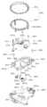
센서충돌 감지장치(200)는 센서(110)를 지지하도록 마련되는 센서 홀더(230)와, 범퍼(210), 그리고 범퍼(210)에 연동하여 센서(110)의 충돌을 감지하는 감지부(220)를 포함할 수 있다.The sensor
센서 홀더(230)는 센서(110)를 지지하도록 마련될 수 있다. 센서 홀더(230)는 센서(110)에 대응되도록 원판으로 형성될 수 있다. 센서 홀더(230)는 원판 형상의 홀더 바디(231)를 포함할 수 있다. 홀더 바디(231)에는 센서 브라켓(114)이 결합될 수 있도록 상측으로 돌출되는 브라켓 고정부(232)가 마련될 수 있다. 브라켓 고정부(232)는 센서 브라켓(114)의 홀더바디 고정부(114a)에 대응되게 마련될 수 있다. 브라켓 고정부(232)와 홀더바디 고정부(114a)를 통해 센서 브라켓(114)이 센서 홀더(230)에 고정될 수 있어, 센서 홀더(230)가 센서(110)를 지지할 수 있다. 센서 브라켓(114)과 센서 홀더(230)는 볼트(160)등을 통해 결합될 수 있다.The
센서 홀더(230)는 센서(110)방향으로 마련되는 제1면(231a)과, 그 반대측의 제2면(231b)을 포함할 수 있다. 제1면(231a)은 센서 바디(111)의 상면이고, 제2면(231b)은 센서 홀더(230)의 하면과 동일하다. 브라켓 고정부(232)는 홀더 바디의 제1면(231a)에 돌출되어 형성될 수 있다.The
센서 홀더(230)는 제1면(231a)에 센서(110)가 지지되도록 마련될 수 있다. 센서 홀더(230)의 제2면(231b)에는 센서충돌 감지장치(200) 중 적어도 일부가 설치될 수 있다. 센서 홀더(230)의 제2면(231b)에는 센서충돌 감지장치(200) 중 범퍼(210)와 감지부(220)가 설치될 수 있다.The
센서 홀더(230)는 범퍼(210)가 설치되기 위한 결합부(235)를 더 포함할 수 있다. 센서 홀더(230)는 감지부(220)가 설치되기 위한 탄성부재 설치부(236)와 스위치 설치부(237)를 더 포함할 수 있다. 센서 홀더(230)의 제2면(231b)에는 범퍼(210)가 설치되기 위한 결합부(235)가 마련될 수 있다. 센서 홀더(230)의 제2면(231b)에는 감지부(220)가 설치되기 위한 탄성부재 설치부(236)와 스위치 설치부(237)가 마련될 수 있다.The
센서 홀더(230)의 결합부(235)에는 범퍼(210)가 이동 가능하게 설치되기 위해 마련되는 고정부재(250)가 결합될 수 있다. 고정부재(250)의 구체적인 구성에 대해서는 후술한다.A fixing
센서충돌 감지장치(200)는 범퍼(210)를 더 포함할 수 있다. 범퍼(210)는 로봇청소기(1)의 주행 중 센서(110) 및 센서(110)를 커버하는 센서 케이스(120)와 장애물의 충돌 시 센서 케이스(120)와 연동하여 감지부(220)를 동작시킬 수 있도록 마련된다.The sensor
범퍼(210)는 센서 케이스(120)의 외측 둘레에 대응되도록 마련될 수 있다. 범퍼(210)는 센서 홀더(230)의 외측 둘레에 대응되도록 마련될 수 있다. 범퍼(210)는 센서 케이스(120)에 대해 상대 이동 가능하게 연결될 수 있다.The
범퍼(210)는 대략 링 형상으로 형성될 수 있다. 범퍼(210)는 센서(110)의 최대 외경내에 배치되도록 마련될 수 있다. 범퍼(210)는 센서 홀더(230)의 하측에 배치되며, 센서 홀더(230)의 최대 외경 내에 배치되도록 마련될 수 있다.The
범퍼(210)는 대략 링 형상의 범퍼 바디(211)를 포함할 수 있다. 범퍼 바디(211)는 적어도 일부는 원 형으로 형성되어 센서(110)의 최대 외경 내에 배치되도록 마련될 수 있다.The
범퍼(210)는 센서 홀더(230)의 하부에서 센서 케이스(120)와 링크부재(130)를 통해 연결될 수 있다. 센서 케이스(120)에 마련된 링크부재(130)의 링크(131) 하단에는 범퍼(210)와 연결을 위한 범퍼 연결부(132)가 마련될 수 있다.The
범퍼(210)에는 링크(131)의 범퍼 연결부(132)에 대응되는 링크 연결부(212)가 마련될 수 있다. 링크 연결부(212)는 범퍼(210)의 내주면에 돌출되어 형성될 수 있다. 링크 연결부(212)는 범퍼 바디(211)의 내주면에 일체로 형성될 수 있다. 링크 연결부(212)는 링크(131)에 대응되는 위치에 대응되는 개수로 형성될 수 있다. 링크 연결부(212)는 범퍼(210)를 센서 케이스(120)에 연동 가능하게 결합시킬 수 있다. 일 실시예에서 범퍼 연결부는 홀로 형성되고 링크 연결부는 돌기인 것을 예를 들어 도시하였으나, 본 발명의 사상은 이에 한정되지 않는다. 링크 연결부는 범퍼가 센서 케이스에 대해 이동 가능하게 연결되도록 구성될 수 있다.A
범퍼(210)는 센서 홀더(230)에 결합되도록 마련되는 결합홀(213)을 더 포함할 수 있다. 범퍼(210)는 센서 홀더(230)에 이동 가능하게 결합되기 위한 결합홀(213)을 포함할 수 있다. 결합홀(213)은 범퍼(210)의 중심부에 마련될 수 있다. 결합홀(213)은 범퍼 바디(211)의 중심부에 마련될 수 있다. 결합홀(213)은 센서 홀더(230)의 결합부(235)에 대응되게 마련될 수 있다. 결합홀(213)은 범퍼(210)가 이동 가능하도록 장방형으로 마련될 수 있다. 결합홀(213)은 타원 형상으로 형성될 수 있다. 범퍼(210)는 범퍼 바디(211)의 내측으로 연장되게 마련되는 연결 리브(218)를 더 포함할 수 있다. 연결 리브(218)는 범퍼 바디(211)와 결합홀(213) 사이를 연결하도록 마련될 수 있다. 연결 리브(218)는 범퍼(210) 중심에 마련된 결합홀(213)을 사이로 좌측과 우측에 각각 연장되어 형성될 수 있다. 연결 리브(218)는 범퍼(210)가 보다 안정적으로 이동될 수 있도록 마련될 수 있다. 연결 리브(218)는 범퍼(210)의 강도를 보강하도록 마련될 수 있다.The
범퍼(210)는 범퍼 바디(211)의 적어도 일부로서, 탄성부재(240) 및/또는 감지부(220)가 설치되기 위한 접촉부(214)를 더 포함할 수 있다. 범퍼(210)의 접촉부(214)는 범퍼 바디(211)의 적어도 일부가 중심 측으로 연장되어 마련될 수 있다.The
범퍼(210)에 마련되는 접촉부(214)는 센서 케이스(120)와 장애물의 충돌을 감지하여 로봇청소기(1)에 전송하도록 후술하는 감지부(220)의 제1스위치(221)와 제2스위치(222) 사이에 마련될 수 있다.The
센서충돌 감지장치(200)는 범퍼(210)를 원래 위치로 복원 가능하도록 텐션을 제공하는 탄성부재(240)를 더 포함할 수 있다. 탄성부재(240)는 스프링을 포함할 수 있다.The sensor
탄성부재(240)는 센서 홀더(230)의 탄성부재 설치부(236)에 설치될 수 있다. 탄성부재(240)는 일측은 탄성부재 설치부(236)에 끼워지고 타측은 범퍼(210)를 탄성 지지하도록 마련될 수 있다.The
범퍼(210)에는 탄성부재(240)가 지지될 수 있도록 평편하게 마련되는 탄성부재 지지부(216)가 마련될 수 있다. 탄성부재 지지부(216)는 범퍼(210)의 접촉부(214) 근처에 마련될 수 있다.The
탄성부재(240)는 센서 케이스(120)와 범퍼(210)가 장애물과 충돌하여 이동 후, 제자리로 돌아갈 수 있도록 센서 홀더(230)와 범퍼(210) 사이를 탄성적으로 지지하도록 마련될 수 있다.The
센서충돌 감지장치(200)는 범퍼(210)와 연동하도록 마련되는 감지부(220)를 더 포함할 수 있다.The sensor
감지부(220)는 범퍼(210)의 적어도 일부와 접촉 가능하도록 소정 각도로 이격되게 서로 마주보게 마련되는 제1스위치(221)와 제2스위치(222)를 포함할 수 있다. 제1스위치(221)와 제2스위치(222)는 서로 마주하는 대향면에 각각 서로 접촉 가능한 제1단자(221a,222a)와 제2단자(221b,222b)를 가질 수 있다.The
센서 홀더(230)는 제1스위치와 제2스위치(222)가 장착되도록 마련되는 스위치 설치부(237)를 더 포함할 수 있다. 스위치 설치부(237)는 센서 홀더(230)의 제2면(231b)에 마련될 수 있다. 스위치 설치부(237)는 경사각을 두고 서로 마주보도록 이격되어 마련될 수 있다. 스위치 설치부(237)는 제1스위치(221)가 설치되기 위한 제1스위치 설치부(237)와 제2스위치(222)가 설치되기 위한 제2스위치 설치부(237)를 포함할 수 있다. 제1스위치 설치부(237)와 제2스위치 설치부(237) 각각은 서로 마주보게 배치되는 한 쌍의 후크를 포함할 수 있다. 제1스위치 설치부(237)의 한 쌍의 후크는 제1스위치(221)의 일측 및 타측을 고정하도록 마련될 수 있다. 제2스위치 설치부(237)의 한 쌍의 후크는 제2스위치(222)의 일측 및 타측을 고정하도록 마련될 수 있다.The
범퍼(210)의 접촉부(214)는 감지부(220)의 제1스위치(221)와 제2스위치(222)에 각각 대응되게 마련될 수 있다. 구체적으로, 범퍼(210)의 접촉부(214)는 제1스위치(221)와 제2스위치(222)에 각각 대응되게 마련되는 제1접촉부(214a)와 제2접촉부(214b)를 포함할 수 있다. 범퍼(210)의 제1접촉부(214a)는 감지부(220)의 제1스위치(221)에 대응되도록 마련될 수 있다. 범퍼(210)의 제2접촉부(214b)는 감지부(220)의 제2스위치(222)에 대응되도록 마련될 수 있다. 범퍼(210)의 제1접촉부(214a)는 제1스위치(221)의 제2단자(221b)를 접촉 및/또는 가압할 수 있도록 마련될 수 있다. 범퍼(210)의 제2접촉부(214b)는 제2스위치(222)의 제2단자(222b)를 접촉 및/또는 가압할 수 있도록 마련될 수 있다.The
도 8 은 도 5 에 도시된 센서유닛의 센서충돌 감지장치의 A-A'부분의 단면도이고, 도 9 는 일 실시예에 따른 센서충돌 감지장치를 나타내는 부분 사시 단면도이며, 도 10 는 도 8 의 B 부분의 확대도이다. 이하에서, 상기한 설명과 중복되는 부분에 대한 설명은 생략한다.8 is a cross-sectional view of the A-A′ portion of the sensor collision detection device of the sensor unit shown in FIG. 5, FIG. 9 is a partial perspective cross-sectional view showing the sensor collision detection device according to an embodiment, and FIG. This is an enlarged view of part B. Hereinafter, descriptions of overlapping parts with the above descriptions will be omitted.
도 8 내지 도 10 에 도시된 바와 같이, 센서유닛(100)의 센서충돌 감지장치(200)는 센서 케이스(120)와 연동하도록 센서 홀더(230)에 이동 가능하게 결합되는 범퍼(210)와, 센서(110)의 충돌을 감지하도록 범퍼(210)의 이동에 연동하는 감지부(220)를 포함할 수 있다. 감지부(220)는 센서 케이스의 충돌을 로봇청소기(1)에 전송하도록 마련될 수 있다.8 to 10, the sensor
센서충돌 감지장치(200)의 범퍼(210)는 고정부재(250)에 의해 센서 홀더(230)에 이동 가능하게 결합될 수 있다.The
고정부재(250)는 센서 홀더(230)에 대해 범퍼(210)가 수평 및 수직 방향으로 이동 가능하게 결합될 수 있도록 마련될 수 있다. 고정부재(250)는 범퍼(210)를 이동 가능하게 지지하는 제1고정부재(251)와, 제1고정부재(251)를 센서 홀더(230)에 고정하기 위해 마련되는 제2고정부재(252)를 포함할 수 있다.The fixing
제1고정부재(251)는 센서 홀더(230)의 결합부(235)에 삽입된 범퍼(210)가 안착될 수 있도록 마련된다. 범퍼(210)와 센서 홀더(230) 사이에는 범퍼(210)가 수직 방향으로 이동 가능하도록 소정의 간극(G)이 마련될 수 있다. 범퍼(210)와 센서 홀더(230)의 제2면(231b) 사이에는 간극(G)이 마련될 수 있다.The
제1고정부재(251)는 센서 홀더(230)의 결합부(235)에 삽입되도록 마련되는 삽입홀(251c)을 갖는 고정바디(251a)와, 고정바디(251a)의 상단에 외측으로 연장되어 형성되는 지지대(251b)를 포함할 수 있다.The
제1고정부재(251)의 고정바디(251a)는 상면과 하면이 개방된 원통 형상으로 형성될 수 있다. 고정바디(251a)는 중심에 센서 홀더(230)의 결합부(235)에 대응되는 삽입홀(251c)이 형성될 수 있다. 지지대(251b)는 고정바디(251a)의 상단으로부터 외측으로 연장되어 마련될 수 있다. 지지대(251b)는 범퍼(210)의 적어도 일부가 안착 및/또는 지지될 수 있도록 평편하게 마련될 수 있다.The fixing
범퍼(210)는 센서 홀더(230)의 결합부(235)에 삽입되어 제1고정부재(251)의 지지대(251b)에 안착될 수 있다. 제1고정부재(251)는 범퍼(210)가 센서 홀더(230)의 제2면(231b)과의 사이에 간극(G)을 가질 수 있도록 제2고정부재(252)를 통해 센서 홀더(230)의 결합부(235)에 고정될 수 있다. 제2고정부재(252)는 센서 홀더(230)의 결합부(235)에 삽입 및 고정되는 볼트 및/또는 나사 등을 포함할 수 있다. 제2고정부재(252)는 센서 홀더(230)의 결합부(235)에 결합된 제1고정부재(251)의 고정바디(251a)를 센서 홀더(230)에 고정하도록 마련될 수 있다. 제2고정부재(252)는 나사부(252a)와 헤드부(252b)를 포함하는 나사를 포함할 수 있다. 제2고정부재의 나사부(252a)는 센서 홀더(230)의 결합부(235)에 삽입될 수 있다. 제2고정부재(252)의 헤드부(252b)는 제1고정부재(251)의 고정바디(251a)의 적어도 일측 단부가 결합부(235)로부터 이탈되지 않도록 지지 및 고정할 수 있다.The
제1고정부재(251)와 제2고정부재(252)에 의해 센서 홀더(230)에 결합되는 범퍼(210)는 센서 홀더(230)의 제2면(231b)과의 사이에 소정 간극(G)을 포함할 수 있다. 이러한 간극(G)에 의해 범퍼(210)는 상하 방향 및 수직 방향으로 이동이 가능하다.The
또한, 센서 홀더(230)에 결합되는 범퍼(210)의 결합홀(213)은 타원 형상으로 마련되어 범퍼(210)를 앞뒤 방향 및 수평 방향 및 회전 이동이 가능하게 할 수 있다.In addition, the
도 11 은 일 실시예에 따른 센서충돌 감지장치의 동작 전 상태를 나타내는 도면이고, 도 12 는 일 실시예에 따른 센서유닛의 정면 충돌 시 센서충돌 감지장치의 상태를 나타내는 도면이며, 도 13 은 일 실시예에 따른 센서유닛의 좌측 충돌 시 센서충돌 감지장치의 상태를 나타내는 도면이고, 도 14 는 일 실시예에 따른 센서유닛의 우측 충돌 시 센서충돌 감지장치의 상태를 나타내는 도면이다. 이하에서, 상기한 설명과 중복되는 부분에 대한 설명은 생략한다.11 is a diagram showing a state before operation of a sensor collision detection device according to an embodiment, FIG. 12 is a diagram showing a state of the sensor collision detection device in case of a frontal collision of a sensor unit according to an embodiment, and FIG. 14 is a diagram showing a state of the sensor collision detection device when a sensor unit collides with the left side according to an embodiment, and FIG. Hereinafter, descriptions of overlapping parts with the above descriptions will be omitted.
도 11를 참조하면, 로봇청소기(1)의 센서유닛(100)은 로봇청소기(1)의 주행 시 청소기본체(10)의 상측에 돌출된 상태에서 장애물을 인식하고 거리를 측정하도록 마련된다.Referring to FIG. 11 , the
로봇청소기(1)의 주행 시, 센서충돌 감지장치(200)의 센서 케이스(120)는 청소기본체(10)의 센서 설치부(13) 상측으로 돌출된 상태로 마련된다.When the
센서 케이스(120)의 내부에 마련되는 센서(110)는 센서 홀더(230)에 회전 가능하게 지지되어 마련될 수 있다.The
범퍼(210)는 센서(110)의 하부에 센서 케이스(120)와 링크(131)를 통해 연결된다. 범퍼(210)는 센서(110)의 최대 외경 내에 배치될 수 있다.The
범퍼(210)는 센서 케이스(120)에 링크(131)를 통해 이동 가능하게 연결될 수 있다.The
범퍼(210)는 센서(110)의 외측 둘레에 대응되도록 마련될 수 있다. 범퍼(210)는 센서 홀더(230)에 소정 각도로 이격되어 배치된 제1스위치(221)와 제2스위치(222)와 각각 인접하게 배치되는 제1접촉부(214a)와 제2접촉부(214b)를 포함할 수 있다. 제1접촉부(214a)와 제2접촉부(214b)는 제1스위치(221)의 제2단자(221b) 및 제2스위치(222)의 제2단자(222b)와 각각 접촉되도록 마련될 수 있다.The
범퍼(210)에 의해 동작되는 제1스위치(221) 및 제2스위치(222)는 제어부(미도시)에 연결되어 로봇청소기(1)에 충돌 감지를 전달할 수 있다.The
범퍼(210)는 센서 홀더(230)와의 사이를 탄성 지지하는 탄성부재(240)에 의해 제1위치(P1)에 위치될 수 있다.The
도 12 를 참고하면, 로봇청소기(1)의 주행 중 센서 케이스(120)의 정면 충돌 시 범퍼(210)는 하측(화살표 방향)으로 이동한다. 범퍼(210)는 제1위치(P1)에서 제2위치(P2)로 이동하게 된다.Referring to FIG. 12 , when the
범퍼(210)가 제2위치(P2)로 이동하면, 범퍼(210)의 제1접촉부(214a) 및 제2접촉부(214b)가 제1스위치(221) 및 제2스위치(222)와 접촉되어 온(ON) 상태가 되고, 로봇청소기(1)에 센서 충돌을 전달한다.When the
스위치(221,222)로 부터 센서 충돌 정보를 전달받은 로봇청소기(1)는 후방으로 이동하여 장애물을 회피할 수 있다.Upon receiving sensor collision information from the
로봇청소기(1)가 이동하면 범퍼(210)는 탄성부재(240)에 의해 원래 위치(제1위치,P1)로 이동될 수 있다.When the
도 13 을 참고하면, 로봇청소기(1)의 주행 중 센서 케이스(120)의 좌측 충돌 시 범퍼(210)는 제1방향(화살표)으로 이동한다. 범퍼(210)는 제1위치(P1)에서 제3위치(P3)로 이동하게 된다.Referring to FIG. 13 , when the
범퍼(210)가 제3위치(P3)로 이동하면, 범퍼(210)의 제1접촉부(214a)는 제1스위치(221)와 접촉되어 제1스위치(221)가 온 상태가 되고, 로봇청소기(1)에 센서 충돌 정보를 전달한다.When the
제1스위치(221)로부터 센서 충돌 정보를 전달받은 로봇청소기(1)는 타측(화살표 반대)으로 이동하여 장애물을 회피할 수 있다.Upon receiving the sensor collision information from the
로봇청소기(1)가 장애물을 피해 이동하면, 범퍼(210)는 원래의 제1위치(P1)로 이동될 수 있다.When the
도 14 를 참고하면, 로봇청소기(1)의 주행 중 센서 케이스(120)의 우측 충돌 시 범퍼(210)는 제2방향(화살표)으로 이동한다. 범퍼(210)는 제1위치(P1)에서 제4위치(P4)로 이동하게 된다.Referring to FIG. 14 , when the right side of the
범퍼(210)가 제4위치(P4)로 이동하면, 범퍼(210)의 제2접촉부(214b)는 제2스위치(222)와 접촉되어 제2스위치(222)가 온 상태가 되고, 로봇청소기(1)에 센서 충돌 정보를 전달한다.When the
제2스위치(222)로부터 센서 충돌 정보를 전달받은 로봇청소기(1)는 타측(화살표 반대)으로 이동하여 장애물을 회피할 수 있다.Upon receiving the sensor collision information from the
로봇청소기(1)가 장애물을 피해 이동하면, 범퍼(210)는 원래의 제1위치(P1)로 이동될 수 있다.When the
이처럼 로봇청소기(1)의 주행 중 센서(110) 및 센서 케이스(120)와 장애물 사이의 충돌 감지를 통해 장애물 분포 상황을 3차원 적으로 파악할 수 있으며, 이를 바탕으로 장애물에 대한 적절한 형태의 회피 또는 극복 주행을 수행할 수 있다.In this way, the obstacle distribution situation can be grasped in three dimensions through the collision detection between the
또한, 로봇청소기(1)는 장애물까지의 거리뿐만 아니라 청소 구역 내의 장애물 분포 상황을 정확하게 파악할 수 있다.In addition, the
도 15 는 일 실시예에 따른 센서충돌 감지장치가 장착된 센서유닛을 나타내는 사시도이고, 도 16 은 도 15 에 도시된 센서충돌 감지장치가 장착된 센서유닛을 나타내는 분해 사시도이며, 도 17 은 도 15 에 도시된 센서충돌 감지장치가 장착된 센서유닛을 저면에서 나타내는 분해 사시도이고, 도 18 은 도 15 에 도시된 센서충돌 감지장치의 B-B'부분의 단면도이며, 도 19 는 도시된 센서충돌 감지장치가 장착된 센서유닛을 나타내는 도면이고, 도 20 은 도 15 에 도시된 센서충돌 감지장치의 감지부를 개략적으로 나타내는 부분 단면도이며, 도 21 은 도 15에 도시된 센서충돌 감지장치의 C - C' 부분의 단면도이다. 미도시된 도면 부호는 도 1 내지 도 14를 참조한다.15 is a perspective view showing a sensor unit equipped with a sensor collision detection device according to an embodiment, FIG. 16 is an exploded perspective view showing a sensor unit equipped with a sensor collision detection device shown in FIG. 15, and FIG. 17 is a perspective view of FIG. 15 is an exploded perspective view showing the sensor unit equipped with the sensor collision detection device shown in , from the bottom, FIG. 18 is a cross-sectional view of the sensor collision detection device shown in FIG. 15 BB', and FIG. FIG. 20 is a partial cross-sectional view schematically illustrating a sensing unit of the sensor collision detection device shown in FIG. 15, and FIG. 21 is C-C' of the sensor collision detection device shown in FIG. 15. section of the part. Reference numerals not shown refer to FIGS. 1 to 14 .
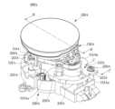
도 15 내지 도 21 에 도시된 바와 같이, 센서유닛(100A)은 센서충돌 감지장치(200A)를 포함할 수 있다.As shown in FIGS. 15 to 21 , the
센서유닛(100A)은 센서(110A)와, 센서(110A)를 커버하도록 마련되는 센서 케이스(120A)를 포함할 수 있다. 센서(110A)는 원통형으로 형성될 수 있다. 센서(110A)는 광을 방출하고 방출된 광이 장애물에 부딪혀 되돌아오는 광을 수신함으로써 장애물의 위치, 장애물과의 거리 등의 장애물 상황 정보를 얻을 수 있다. 이와 같이 얻어진 장애물 상황 정보는 로봇청소기(1)의 주행에 반영될 수 있다.The
센서(110A)는 원통형의 센서 바디(111A)와, 센서 바디(111A)의 내부에 마련되는 센싱부(미도시)를 포함할 수 있다. 센서 바디(111A)의 적어도 일부에는 센서(110A)가 방출하는 광과 장애물에 부딪혀 되돌아오는 광이 원활하게 통과되도록 하기 위한 센싱개구(111Aa)가 마련될 수 있다. 센싱개구(111Aa)는 센서 바디(111A)의 외주면에 적어도 하나 이상 형성될 수 있다. 센싱개구(111Aa)는 원주 방향을 따라 개방되도록 형성될 수 있다.The
센서유닛(100A)은 센서(110A)를 회전 가능하게 하기 위한 구동부(112A)를 더 포함할 수 있다. 구동부(112A)는 모터(112Aa)와 모터축(112Ab)에 연결되어 센서(110A)를 회전시키도록 마련되는 벨트(112Ac)를 포함할 수 있다.The
센서(110A)는 센서 바디(111A)의 하부를 수용하도록 마련되는 센서 브라켓(114A)을 포함할 수 있다. 센서 브라켓(114A)은 센서(110A)가 회전 가능하게 결합되도록 마련될 수 있다. 센서 브라켓(114A)의 일측에는 구동부(112A)가 설치되기 위한 구동부설치부(114Ab)가 마련될 수 있다.The
센서 브라켓(114A)은 후술하는 센서충돌 감지장치(200A)의 센서 홀더(230A)에 센서(110A)가 지지될 수 있도록 홀더바디 고정부(114Aa)가 마련될 수 있다. 홀더바디 고정부(114Aa)는 센서 브라켓(114A)의 하측으로 돌출 형성될 수 있다. 홀더바디 고정부(114Aa)는 센서 브라켓(114A)의 적어도 일부에 연장되어 형성될 수 있다.The
구동부설치부(114Ab)는 모터(112Aa)와, 모터축(112Ab)에 연결된 벨트(112Ac)가 센서(110A)와 연결될 수 있도록 구성될 수 있다. 본 실시예에서 구동부설치부는 센서바디의 외측에 배치되는 것을 예를 들어 도시하였으나, 이에 한정되지 않는다. 예를 들어 센서를 회전시키기 위해 마련되는 구동부는 센서바디 및/또는 센서 브라켓의 내측에 배치될 수도 있다. The drive unit installation unit 114Ab may be configured such that the motor 112Aa and the belt 112Ac connected to the motor shaft 112Ab may be connected to the
센서(110A)는 센서 케이스(120A)에 의해 커버될 수 있다. 센서(110A)는 센서 케이스(120A)의 내측에 위치될 수 있다.The
센서 케이스(120A)는 센서(110A)의 상부를 커버하는 제1센서케이스(121A)와, 제1센서케이스(121A)에 결합되는 제2센서케이스(122A)를 포함할 수 있다. 제1센서케이스(121A)는 센서(110A)의 상면을 커버하도록 판 형상으로 마련될 수 있다. 제2센서케이스(122A)는 제1센서케이스(121A)에 결합될 수 있도록 링 형상으로 마련될 수 있다.The
제2센서케이스(이하, '센서 케이스'라 함)에는 후술하는 센서충돌 감지장치(200A)와 센서 케이스(120A)를 연결하기 위한 링크부재(130A)가 마련될 수 있다.A
센서충돌 감지장치(200A)는 센서(110A)의 하부에 배치될 수 있다. 센서충돌 감지장치(200A)는 링크부재(130A)를 통해 센서 케이스(120A)에 연결될 수 있다. 링크부재(130A)는 센서 케이스(120A)에 일체로 연장되어 마련될 수 있다. 센서충돌 감지장치(200A)는 센서 케이스(120A)와 장애물의 충돌 시, 링크부재(130A)를 통해 충돌을 감지할 수 있도록 마련된다.The sensor
링크부재(130A)는 적어도 하나 이상의 링크(131A)를 포함할 수 있다. 링크(131A)는 케이스(120A)와 일체로 마련될 수 있다. 링크(131A)는 케이스(120A)와 센서충돌 감지장치(200A)를 연결하도록 마련될 수 있다.The
센서충돌 감지장치(200A)는 범퍼(210A), 범퍼(210A)에 연동하여 센서(110A)의 충돌을 감지하는 감지부(220A), 센서(110A)를 지지하도록 마련되는 센서 홀더(230A)를 포함할 수 있다.The sensor
센서 홀더(230A)는 센서(110A)를 지지하도록 마련될 수 있다. 센서 홀더(230A)는 센서(110A)에 대응되도록 형성될 수 있다.The
센서 홀더(230A)는 상면이 개방된 원통 형상의 홀더 바디(231A)를 포함할 수 있다. 홀더 바디(231)에는 센서 브라켓(114A)이 결합될 수 있도록 상측으로 돌출되는 브라켓 고정부(232A)가 마련될 수 있다.The
브라켓 고정부(232A)는 센서 브라켓(114A)의 홀더바디 고정부(114Aa)에 대응되게 마련될 수 있다. 브라켓 고정부(232A)와 홀더바디 고정부(114Aa)를 통해 센서 브라켓(114A)이 센서 홀더(230A)에 고정될 수 있어, 센서 홀더(230A)가 센서(110A)를 지지할 수 있다. 센서 브라켓(114A)과 센서 홀더(230A)는 볼트(160A)등을 통해 결합될 수 있다.The
센서 홀더(230A)는 감지부(220A)를 수용하도록 마련되는 감지부수용부(233A)를 더 포함할 수 있다. 센서 홀더(230A)에는 범퍼(210A)와 감지부(220A)가 설치될 수 있다.The
센서 홀더(230A)는 범퍼(210A)와 결합되기 위한 결합부(235A)를 더 포함할 수 있다. 센서 홀더(230A)는 탄성부재 설치부(236A)와 스위치 설치부(237A)를 더 포함할 수 있다.The
센서 홀더(230A)의 결합부(235A)에는 범퍼(210A)가 이동 가능하게 설치되기 위해 마련되는 고정부재(250A)가 결합될 수 있다. 고정부재(250A)의 구체적인 구성에 대해서는 후술한다.A fixing
센서충돌 감지장치(200A)는 범퍼(210A)를 더 포함할 수 있다. 범퍼(210A)는 로봇청소기(1)의 주행 중 센서(110A) 및 센서(110A)를 커버하는 센서 케이스(120A)와 장애물의 충돌 시 센서 케이스(120A)와 연동하여 감지부(220A)를 동작시킬 수 있도록 마련된다.The sensor
범퍼(210A)는 센서 케이스(120A)에 대해 상대 이동 가능하게 연결될 수 있다. 범퍼(210A)는 대략 센서 케이스(120A)의 외측 둘레에 대응되게 형성될 수 있다. 범퍼(210A)는 대략 판 형상으로 형성될 수 있다. 범퍼(210A)는 센서(110A)의 최대 외경 내에 배치되도록 마련될 수 있다. 범퍼(210A)는 센서(110A)의 하측에 배치되고, 센서 홀더(230A)의 상측에 배치된다. 범퍼(210A)는 센서 홀더(230A)의 최대 외경 내에 배치되도록 마련될 수 있다.The
범퍼(210A)는 범퍼 바디(211A)를 포함할 수 있다. 범퍼 바디(211A)의 적어도 일부는 곡면으로 형성되어 센서(110A)의 최대 외경 내에 배치되도록 마련될 수 있다.The
범퍼(210A)는 센서 케이스(120A)와 링크부재(130A)를 통해 연결될 수 있다. 범퍼(210A)는 링크부재(130A)의 링크(131A)가 연결되도록 마련되는 링크연결부(212A)를 포함할 수 있다. 링크연결부(212A)는 링크(131A)의 개수에 대응되게 마련될 수 있다. 링크 연결부(212A)는 범퍼(210A)의 상측으로 돌출되어 형성될 수 있다. 링크 연결부(212A)는 범퍼 바디(211A)에 일체로 형성될 수 있다. 링크 연결부(212A)는 범퍼(210A)를 센서 케이스(120A)와 연동 가능하게 결합시킬 수 있다.The
범퍼(210A)는 센서(110A)의 모터(112Aa)가 관통되어 설치될 수 있도록 적어도 일부가 절개되어 형성되는 구동부설치부(215A)가 마련될 수 있다. 구동부설치부(215A)는 범퍼 바디(211A)의 일측에 센서(110A)의 모터(112Aa)에 대응되는 위치에 형성될 수 있다.At least a part of the
범퍼(210A)는 센서 홀더(230A)에 결합되도록 마련되는 결합홀(213A)을 더 포함할 수 있다. 범퍼(210A)는 센서 홀더(230A)에 이동 가능하게 결합되기 위한 결합홀(213A)을 포함할 수 있다. 결합홀(213A)은 외측 테두리에 형성될 수 있다. 결합홀(213A)은 범퍼 바디(211A)의 외측 테두리에 적어도 일부가 절개되어 형성될 수 있다. 결합홀(213A)은 센서 홀더(230A)의 결합부(235A)에 대응되게 마련될 수 있다. 결합홀(213A)은 범퍼(210A)가 이동 가능하도록 장방형으로 마련될 수 있다. 결합홀(213A)은 타원 형상으로 형성될 수 있다.The
범퍼(210A)는 범퍼 바디(211A)의 하측으로 연장되는 범퍼바디 지지부(211Ab)를 포함할 수 있다. 범퍼바디 지지부(211Ab)는 범퍼(210A)를 센서 홀더(230A)에 안정적으로 지지하도록 마련될 수 있다. 범퍼바디 지지부(211Ab)는 홀더 바디(231A)의 적어도 일부에 지지되도록 마련될 수 있다.The
범퍼(210A)는 범퍼 바디(211A) 하측면에 형성되는 범퍼 가이드홈(211Aa)을 더 포함할 수 있다. 범퍼 가이드홈(211Aa)은 범퍼(210A)의 이동을 가이드 할 수 있도록 장방형으로 형성될 수 있다. 센서 홀더(230A)의 홀더 바디(231A)에는 범퍼(210A)의 범퍼 가이드홈(211Aa)에 대응되는 범퍼 가이드(231Aa)가 마련될 수 있다. 범퍼 가이드(231Aa)는 홀더 바디(230A)의 상면에 돌출되게 형성될 수 있다.The
범퍼(210A)는 탄성부재(240A)가 지지되기 위한 탄성지지부(214A)를 더 포함할 수 있다. 범퍼(210A)의 탄성지지부(214A)는 범퍼 바디(211A)의 저면으로부터 하측으로 연장되어 마련될 수 있다. 범퍼(210A)의 탄성지지부(214A)는 센서 홀더(230A)의 탄성부재 설치부(214A)에 대응되는 위치에 마련될 수 있다.The
범퍼(210A)에 마련되는 탄성지지부(214A)는 센서 케이스(120A)와 장애물의 충돌을 감지하여 로봇청소기(1)에 전송하도록 후술하는 감지부(220A)의 제1스위치(221A)와 제2스위치(222A) 사이에 마련될 수 있다.The
범퍼(210A)는 제1스위치(221A)와 제2스위치(222A)와 접촉하도록 마련되는 접촉부(216A)를 더 포함할 수 있다. 접촉부(216A)는 탄성지지부(214A)와 일체로 연장되어 형성될 수 있다.The
센서충돌 감지장치(200A)는 센서 케이스(120A)와 장애물의 충돌에 의해 이동된 범퍼(210A)를 원래 위치로 복원 가능하도록 텐션을 제공하는 탄성부재(240A)를 더 포함할 수 있다. 탄성부재(240A)는 스프링을 포함할 수 있다.The sensor
탄성부재(240A)는 센서 홀더(230A)의 탄성부재 설치부(236A)에 설치될 수 있다. 탄성부재(240A)는 일측은 탄성부재 설치부(236A)에 끼워지고 타측은 범퍼(210A)를 탄성 지지하도록 마련될 수 있다. 탄성부재(240A)는 센서 케이스(120A)와 범퍼(210A)가 장애물과 충돌하여 이동 후, 제자리로 돌아갈 수 있도록 센서 홀더(230A)와 범퍼(210A) 사이를 탄성적으로 지지하도록 마련될 수 있다.The
센서충돌 감지장치(200A)는 범퍼(210A)와 연동하도록 마련되는 감지부(220A)를 더 포함할 수 있다.The sensor
감지부(220A)는 범퍼(210A)의 적어도 일부와 접촉 가능하도록 소정 각도로 이격되게 서로 마주보게 마련되는 제1스위치(221A)와 제2스위치(222A)를 포함할 수 있다. 제1스위치(221A)와 제2스위치(222A)는 서로 마주하는 대향면에 각각 서로 접촉 가능한 제1단자(221Aa,222Aa)와 제2단자(221Ab,222Ab)를 가질 수 있다.The
범퍼(210A)의 접촉부(216A)는 감지부(220A)의 제1스위치(221A)와 제2스위치(222A)에 각각 대응되게 마련될 수 있다. 구체적으로, 접촉부(216A)는 제1스위치(221A)와 제2스위치(222A)에 각각 대응되게 마련되는 제1접촉부(216Aa)와 제2접촉부(216Ab)를 포함할 수 있다. 제1접촉부(216Aa)는 제1스위치(221A)에 대응되도록 마련될 수 있다. 제2접촉부(216Ab)는 제2스위치(222A)에 대응되도록 마련될 수 있다. 제1접촉부(216Aa)는 제1스위치(221A)의 제2단자(221Ab)를 접촉 및/또는 가압할 수 있도록 마련될 수 있다. 제2접촉부(214Ab)는 제2스위치(222A)의 제2단자(222Ab)를 접촉 및/또는 가압할 수 있도록 마련될 수 있다.The contact portion 216A of the
센서충돌 감지장치(200)의 범퍼(210)는 고정부재(250)에 의해 센서 홀더(230)에 이동 가능하게 결합될 수 있다.The
도 21 에 도시된 바와 같이, 범퍼(210A)는 센서 홀더(230A)에 대해 수평 및 수직 방향으로 이동 가능하게 결합될 수 있도록 마련된다.As shown in FIG. 21 , the
범퍼(210A)는 고정부재(250A) 센서 홀더(230A)에 대해 수평 및 수직 방향으로 이동 가능하도록 결합될 수 있다.The
고정부재(250A)는 나사부(251A)와 헤드부(252A)를 포함하는 나사를 포함할 수 있다. 고정부재(250A)의 나사부(251A)는 센서 홀더(230A)의 결합부(235A)에 삽입될 수 있다. 고정부재(250A)의 헤드부(252A)는 나사부(251A) 보다 큰 직경으로 형성될 수 있다.The fixing
센서 홀더(230A)의 결합부(235A)에는 고정부재(250A)가 결합되기 위한 결합홈(235Aa)이 형성될 수 있다. 결합홈(235Aa)에는 나사부(251A)가 결합될 수 있다.A coupling groove 235Aa for coupling the fixing
범퍼(210A)와 센서 홀더(230A) 사이에는 범퍼(210A)가 수직 방향으로 이동 가능하도록 간극(G)이 형성될 수 있다. 고정부재(250A)는 범퍼(210A)와 센서 홀더(230A) 사이에 간극(G)이 형성될 수 있도록 범퍼(210A)와 센서 홀더(230A)를 결합할 수 있다. 고정부재(250A)의 헤드부(252A)는 범퍼(210A)의 결합홀(213A)과의 사이에 간극(G)이 마련되도록 결합될 수 있다.A gap G may be formed between the
이러한 간극(G)에 의해 범퍼(210A)는 센서 홀더(230A)에 대해 상하 방향 이동이 가능할 수 있다.Due to the gap G, the
또한, 범퍼(210A)의 결합홀(213A)은 장방형의 타원 형상으로 형성되어 범퍼(210A)를 센서 홀더(230A)에 대해 수직 및 수평 및 회전 이동이 가능하게 할 수 있다.In addition, the
이상에서는 특정의 실시예에 대하여 도시하고 설명하였다. 그러나, 상기한 실시예에만 한정되지 않으며, 발명이 속하는 기술분야에서 통상의 지식을 가진 자라면 이하의 청구범위에 기재된 발명의 기술적 사상의 요지를 벗어남이 없이 얼마든지 다양하게 변경 실시할 수 있을 것이다.In the above, specific embodiments have been illustrated and described. However, it is not limited to the above embodiments, and those skilled in the art will be able to make various changes without departing from the gist of the technical idea of the invention described in the claims below. .
1: 로봇 청소기10 : 청소기 본체
13 : 센서 설치부100 : 센서 유닛
110 : 센서120 : 센서 케이스
130 : 링크부재131 : 링크
132 : 범퍼 연결부200 : 센서충돌 감지장치
210 : 범퍼220 : 감지부
221,222 : 제1,2 스위치230 : 센서 홀더
240 : 탄성부재1: robot cleaner 10: cleaner body
13: sensor installation unit 100: sensor unit
110: sensor 120: sensor case
130: link member 131: link
132: bumper connection 200: sensor collision detection device
210: bumper 220: detection unit
221,222: first and second switches 230: sensor holder
240: elastic member
Claims (20)
Translated fromKorean상기 청소기본체에 마련되고, 상기 청소구역 내의 장애물을 감지하는 센서를 커버하도록 마련되는 센서 케이스; 및
상기 센서에 가해지는 충격을 감지하도록 마련되는 센서충돌 감지장치;를 포함하고,
상기 센서충돌 감지장치는,
상기 센서 케이스에 이동 가능하게 연결되고, 적어도 일부가 상기 센서의 외측 둘레에 대응되도록 마련되는 범퍼와,
상기 센서 케이스의 충돌을 감지하도록 상기 범퍼와 연동하는 감지부를 포함하며,
상기 범퍼와 상기 감지부는 상기 센서의 하측에 배치되는 로봇청소기.a cleaner main body that travels and cleans the cleaning area;
a sensor case provided in the cleaning main body and provided to cover a sensor that detects an obstacle in the cleaning area; and
Including; a sensor collision detection device provided to detect an impact applied to the sensor,
The sensor collision detection device,
A bumper movably connected to the sensor case and provided so that at least a portion thereof corresponds to an outer circumference of the sensor;
A sensing unit interlocking with the bumper to detect a collision of the sensor case;
The robot cleaner of claim 1 , wherein the bumper and the sensing unit are disposed below the sensor.
상기 센서충돌 감지장치는,
상기 센서를 지지하도록 마련되는 센서 홀더를 더 포함하고,
상기 범퍼와 상기 감지부는 상기 센서 홀더의 저면에 배치되는 로봇청소기.According to claim 1,
The sensor collision detection device,
Further comprising a sensor holder provided to support the sensor,
The robot cleaner of claim 1 , wherein the bumper and the sensing unit are disposed on a lower surface of the sensor holder.
상기 범퍼와 상기 감지부는 상기 센서 홀더의 하부에 동일 선상에 배치되는 로봇청소기.According to claim 2,
The robot cleaner of claim 1 , wherein the bumper and the sensing unit are disposed on the same line under the sensor holder.
상기 센서충돌 감지장치는,
상기 센서 케이스와 장애물의 충돌 시, 상기 센서 케이스와 상기 범퍼가 연동될 수 있도록 연결하는 링크부재를 더 포함하고,
상기 링크부재는 상기 센서 케이스의 원주 방향으로 이격되어 배치되는 적어도 하나의 링크를 포함하는 로봇청소기.According to claim 2,
The sensor collision detection device,
Further comprising a link member connecting the sensor case and the bumper so that they can be interlocked when the sensor case collides with an obstacle,
The link member includes at least one link spaced apart from each other in a circumferential direction of the sensor case.
상기 센서충돌 감지장치는,
상기 범퍼가 연결되도록 상기 링크에 마련되는 범퍼 연결부와,
상기 범퍼 연결부에 대응되도록 상기 범퍼에 마련되는 링크 연결부를 더 포함하는 로봇청소기.According to claim 4,
The sensor collision detection device,
A bumper connecting portion provided on the link so that the bumper is connected;
The robot cleaner further comprises a link connecting portion provided on the bumper to correspond to the bumper connecting portion.
상기 센서충돌 감지장치는,
상기 범퍼를 원래 위치로 복원 가능하도록 텐션을 제공하는 탄성부재를 더 포함하는 로봇청소기.According to claim 2,
The sensor collision detection device,
The robot cleaner further includes an elastic member providing tension to restore the bumper to its original position.
상기 감지부는,
상기 범퍼의 적어도 일부와 접촉 가능하도록 소정 각도로 이격되게 서로 마주보게 마련되고, 대향면에 각각 서로 접촉 가능한 제1단자와 제2단자를 가지는 한 쌍의 제1스위치 및 제2스위치를 포함하는 로봇청소기.According to claim 6,
the sensor,
A robot including a pair of first and second switches provided to face each other spaced apart at a predetermined angle so as to be in contact with at least a portion of the bumper, and having first and second terminals contactable to each other on opposite surfaces, respectively. vacuum cleaner.
상기 범퍼는,
상기 센서 케이스의 외측 둘레에 대응되도록 형성되는 범퍼 바디와,
상기 범퍼 바디의 적어도 일부로서, 상기 제1스위치 및 제2스위치 사이에 배치되고, 각각의 상기 제2단자를 가압하여 상기 제1단자에 접촉하도록 마련되는 접촉부를 포함하는 로봇청소기.According to claim 7,
the bumper,
A bumper body formed to correspond to the outer circumference of the sensor case;
and a contact portion disposed between the first switch and the second switch as at least a part of the bumper body and provided to press each of the second terminals to contact the first terminals.
상기 센서충돌 감지장치는,
상기 범퍼가 상기 센서 홀더에 이동 가능하게 결합되도록 마련되는 고정부재를 더 포함하고,
상기 고정부재는 상기 범퍼가 안착되는 제1고정부재와,
상기 제1고정부재를 상기 센서 홀더에 고정시키는 제2고정부재를 포함하는 로봇청소기.According to claim 8,
The sensor collision detection device,
The bumper further includes a fixing member provided to be movably coupled to the sensor holder,
The fixing member includes a first fixing member on which the bumper is seated;
A robot cleaner comprising a second fixing member fixing the first fixing member to the sensor holder.
상기 범퍼와 상기 센서 홀더의 하면 사이에 간극(G)이 마련되는 로봇청소기.According to claim 9,
A robot cleaner in which a gap (G) is provided between the lower surface of the bumper and the sensor holder.
상기 센서 홀더는,
상기 고정부재가 결합되도록 상기 센서 홀더의 하면에 마련되는 결합부를 더 포함하고,
상기 결합부는 상기 범퍼와 상기 제1고정부재가 결합되도록 마련되는 결합돌기와,
상기 제2고정부재가 결합되도록 상기 결합돌기에 형성되는 결합홈을 포함하는 로봇청소기.According to claim 10,
The sensor holder,
Further comprising a coupling portion provided on a lower surface of the sensor holder so that the fixing member is coupled,
The coupling portion includes a coupling protrusion provided to couple the bumper and the first fixing member;
A robot cleaner comprising a coupling groove formed on the coupling protrusion to engage the second fixing member.
상기 범퍼는,
상기 고정부재가 결합되도록 상기 결합부에 대응되게 마련되는 결합홀을 더 포함하고,
상기 결합홀은 타원 형상으로 형성되는 로봇청소기.According to claim 11,
the bumper,
Further comprising a coupling hole provided to correspond to the coupling portion so that the fixing member is coupled,
The coupling hole is a robot cleaner formed in an elliptical shape.
상기 센서 홀더는,
상기 탄성부재가 결합되도록 상기 센서 홀더의 하면에 마련되는 탄성부재 설치부를 더 포함하는 로봇청소기.According to claim 11,
The sensor holder,
The robot cleaner further includes an elastic member installation portion provided on a lower surface of the sensor holder to couple the elastic member.
상기 범퍼는,
상기 탄성부재가 지지되도록 상기 탄성부재 설치부와 이격되어 마련되는 탄성부재 지지부를 더 포함하는 로봇청소기.According to claim 13,
the bumper,
The robot cleaner further includes an elastic member support portion provided to be spaced apart from the elastic member installation portion to support the elastic member.
상기 청소기본체에 마련되고, 상기 청소구역 내의 장애물을 감지하는 센서를 커버하도록 마련되는 센서 케이스; 및
상기 센서에 가해지는 충격을 감지하도록 마련되는 센서충돌 감지장치;를 포함하고,
상기 센서충돌 감지장치는,
상기 센서 케이스의 내측에서 상기 센서를 지지하도록 마련되는 센서 홀더와,
상기 센서 케이스에 상대이동 가능하게 연결되고, 적어도 일부가 상기 센서의 외측 둘레와 대응되도록 마련되는 범퍼와,
상기 센서 케이스의 충돌을 감지하도록 상기 범퍼와 연동하는 감지부를 포함하며,
상기 범퍼와 상기 감지부는 상기 센서 홀더의 하부에 배치되는 로봇청소기.a cleaner main body that travels and cleans the cleaning area;
a sensor case provided in the cleaning main body and provided to cover a sensor that detects an obstacle in the cleaning area; and
Including; a sensor collision detection device provided to detect an impact applied to the sensor,
The sensor collision detection device,
A sensor holder provided to support the sensor inside the sensor case;
a bumper connected to the sensor case so as to be relatively movable and having at least a portion corresponding to an outer circumference of the sensor;
A sensing unit interlocking with the bumper to detect a collision of the sensor case;
The robot cleaner of claim 1 , wherein the bumper and the sensing unit are disposed below the sensor holder.
상기 센서충돌 감지장치는,
상기 센서 케이스와 장애물의 충돌 시, 상기 센서 케이스와 상기 범퍼가 연동될 수 있도록 연결하는 링크부재를 더 포함하고,
상기 링크부재는 상기 센서 케이스의 원주 방향으로 이격되어 배치되는 적어도 하나의 링크를 포함하는 로봇청소기.According to claim 15,
The sensor collision detection device,
Further comprising a link member connecting the sensor case and the bumper so that they can be interlocked when the sensor case collides with an obstacle,
The link member includes at least one link spaced apart from each other in a circumferential direction of the sensor case.
상기 센서충돌 감지장치는,
상기 범퍼가 연결되도록 상기 링크에 마련되는 범퍼 연결부와,
상기 범퍼 연결부에 대응되도록 상기 범퍼에 마련되는 링크 연결부를 더 포함하는 로봇청소기.17. The method of claim 16,
The sensor collision detection device,
A bumper connecting portion provided on the link so that the bumper is connected;
The robot cleaner further comprises a link connecting portion provided on the bumper to correspond to the bumper connecting portion.
상기 센서충돌 감지장치는,
상기 범퍼를 원래 위치로 복원 가능하도록 텐션을 제공하는 탄성부재를 더 포함하는 로봇청소기.According to claim 15,
The sensor collision detection device,
The robot cleaner further includes an elastic member providing tension to restore the bumper to its original position.
상기 감지부는,
상기 범퍼의 적어도 일부와 접촉 가능하도록 소정 각도로 이격되게 서로 마주보게 마련되고, 대향면에 각각 서로 접촉 가능한 제1단자와 제2단자를 가지는 한 쌍의 제1스위치 및 제2스위치를 포함하는 로봇청소기.According to claim 18,
the sensor,
A robot including a pair of first and second switches provided to face each other spaced apart at a predetermined angle so as to be in contact with at least a portion of the bumper, and having first and second terminals contactable to each other on opposite surfaces, respectively. vacuum cleaner.
상기 범퍼는,
상기 센서 케이스의 외측 둘레에 대응되도록 형성되는 범퍼 바디와,
상기 범퍼 바디의 적어도 일부로서, 상기 제1스위치 및 제2스위치 사이에 배치되고, 각각의 상기 제2단자를 가압하여 상기 제1단자에 접촉하도록 마련되는 접촉부와,
상기 탄성부재가 지지되도록 상기 탄성부재 설치부와 이격되어 마련되는 탄성부재 지지부를 포함하는 로봇청소기.According to claim 19,
the bumper,
A bumper body formed to correspond to the outer circumference of the sensor case;
At least a part of the bumper body, disposed between the first switch and the second switch, and a contact portion provided to contact the first terminal by pressing each of the second terminals;
A robot cleaner comprising an elastic member support portion provided to be spaced apart from the elastic member installation portion to support the elastic member.
Priority Applications (4)
| Application Number | Priority Date | Filing Date | Title |
|---|---|---|---|
| KR1020220019660AKR20230122878A (en) | 2022-02-15 | 2022-02-15 | Washing machine |
| PCT/KR2022/020974WO2023158089A1 (en) | 2022-02-15 | 2022-12-21 | Robot cleaner |
| EP22927485.7AEP4454528A1 (en) | 2022-02-15 | 2022-12-21 | Robot cleaner |
| US18/771,288US20240358214A1 (en) | 2022-02-15 | 2024-07-12 | Robot cleaner |
Applications Claiming Priority (1)
| Application Number | Priority Date | Filing Date | Title |
|---|---|---|---|
| KR1020220019660AKR20230122878A (en) | 2022-02-15 | 2022-02-15 | Washing machine |
Publications (1)
| Publication Number | Publication Date |
|---|---|
| KR20230122878Atrue KR20230122878A (en) | 2023-08-22 |
Family
ID=87578803
Family Applications (1)
| Application Number | Title | Priority Date | Filing Date |
|---|---|---|---|
| KR1020220019660APendingKR20230122878A (en) | 2022-02-15 | 2022-02-15 | Washing machine |
Country Status (4)
| Country | Link |
|---|---|
| US (1) | US20240358214A1 (en) |
| EP (1) | EP4454528A1 (en) |
| KR (1) | KR20230122878A (en) |
| WO (1) | WO2023158089A1 (en) |
Family Cites Families (5)
| Publication number | Priority date | Publication date | Assignee | Title |
|---|---|---|---|---|
| KR100492588B1 (en)* | 2003-01-23 | 2005-06-03 | 엘지전자 주식회사 | Position information recognition apparatus for automatic running vacuum cleaner |
| JPWO2018225172A1 (en)* | 2017-06-07 | 2019-11-07 | 学校法人千葉工業大学 | Self-propelled vacuum cleaner |
| KR102791416B1 (en)* | 2019-06-04 | 2025-04-08 | 삼성전자주식회사 | A robot cleaner |
| JP7430540B2 (en)* | 2020-02-03 | 2024-02-13 | 株式会社マキタ | Detection device and robot dust collector |
| KR20210117810A (en)* | 2020-03-20 | 2021-09-29 | 엘지전자 주식회사 | Robot vacuum cleaner |
- 2022
- 2022-02-15KRKR1020220019660Apatent/KR20230122878A/enactivePending
- 2022-12-21EPEP22927485.7Apatent/EP4454528A1/enactivePending
- 2022-12-21WOPCT/KR2022/020974patent/WO2023158089A1/ennot_activeCeased
- 2024
- 2024-07-12USUS18/771,288patent/US20240358214A1/enactivePending
Also Published As
| Publication number | Publication date |
|---|---|
| US20240358214A1 (en) | 2024-10-31 |
| EP4454528A1 (en) | 2024-10-30 |
| WO2023158089A1 (en) | 2023-08-24 |
Similar Documents
| Publication | Publication Date | Title |
|---|---|---|
| US7992251B2 (en) | Robot and method for controlling the robot | |
| US11096545B2 (en) | Robot cleaner | |
| US11103115B2 (en) | Sensor module and robot cleaner having the same | |
| JP5935215B2 (en) | Autonomous cleaning appliances | |
| EP1897476B1 (en) | Cleaning robot | |
| KR20200067142A (en) | robotic vacuum | |
| KR101939672B1 (en) | Electric cleaner | |
| US20230145580A1 (en) | Robot cleaner | |
| KR20180106225A (en) | Robot cleaner | |
| KR20140061491A (en) | Autonomous vacuum cleaner | |
| JP2003280740A (en) | Moving equipment | |
| WO2015163374A1 (en) | Autonomous traveling body | |
| JP2020068897A (en) | Cleaning robot | |
| CN113876253B (en) | Cleaning Robot | |
| KR20180089932A (en) | A Robot cleaner protected collision | |
| KR20230122878A (en) | Washing machine | |
| US20220167815A1 (en) | Robot cleaner | |
| JP7710135B2 (en) | Autonomous Vacuum Cleaner | |
| KR101851587B1 (en) | Sensor assembly for robot cleaner | |
| KR20020080900A (en) | Obstacle detecting apparatus of robot cleaner and method therefor | |
| KR101836980B1 (en) | Robot cleaner | |
| JP7369592B2 (en) | Detection device and robot dust collector | |
| JP2018112799A (en) | Autonomously moving vacuum cleaner | |
| KR100548298B1 (en) | Collision Detection Device of Robot Cleaner | |
| US20250248575A1 (en) | Detection device and robot dust collector |
Legal Events
| Date | Code | Title | Description |
|---|---|---|---|
| PA0109 | Patent application | Patent event code:PA01091R01D Comment text:Patent Application Patent event date:20220215 | |
| PG1501 | Laying open of application | ||
| A201 | Request for examination | ||
| PA0201 | Request for examination | Patent event code:PA02012R01D Patent event date:20250212 Comment text:Request for Examination of Application |