KR20230119007A - Two-stroke internal combustion piston engine and assembly for direct injection of gaseous fuel in the cylinder of a two-stroke internal combustion piston engine - Google Patents
Two-stroke internal combustion piston engine and assembly for direct injection of gaseous fuel in the cylinder of a two-stroke internal combustion piston engineDownload PDFInfo
- Publication number
- KR20230119007A KR20230119007AKR1020237024760AKR20237024760AKR20230119007AKR 20230119007 AKR20230119007 AKR 20230119007AKR 1020237024760 AKR1020237024760 AKR 1020237024760AKR 20237024760 AKR20237024760 AKR 20237024760AKR 20230119007 AKR20230119007 AKR 20230119007A
- Authority
- KR
- South Korea
- Prior art keywords
- liquefied gas
- assembly
- enclosure
- engine
- cylinder
- Prior art date
- Legal status (The legal status is an assumption and is not a legal conclusion. Google has not performed a legal analysis and makes no representation as to the accuracy of the status listed.)
- Granted
Links
Images

Classifications
- F—MECHANICAL ENGINEERING; LIGHTING; HEATING; WEAPONS; BLASTING
- F02—COMBUSTION ENGINES; HOT-GAS OR COMBUSTION-PRODUCT ENGINE PLANTS
- F02M—SUPPLYING COMBUSTION ENGINES IN GENERAL WITH COMBUSTIBLE MIXTURES OR CONSTITUENTS THEREOF
- F02M21/00—Apparatus for supplying engines with non-liquid fuels, e.g. gaseous fuels stored in liquid form
- F02M21/02—Apparatus for supplying engines with non-liquid fuels, e.g. gaseous fuels stored in liquid form for gaseous fuels
- F02M21/0203—Apparatus for supplying engines with non-liquid fuels, e.g. gaseous fuels stored in liquid form for gaseous fuels characterised by the type of gaseous fuel
- F02M21/0209—Hydrocarbon fuels, e.g. methane or acetylene
- F02M21/0212—Hydrocarbon fuels, e.g. methane or acetylene comprising at least 3 C-Atoms, e.g. liquefied petroleum gas [LPG], propane or butane
- F—MECHANICAL ENGINEERING; LIGHTING; HEATING; WEAPONS; BLASTING
- F02—COMBUSTION ENGINES; HOT-GAS OR COMBUSTION-PRODUCT ENGINE PLANTS
- F02D—CONTROLLING COMBUSTION ENGINES
- F02D19/00—Controlling engines characterised by their use of non-liquid fuels, pluralities of fuels, or non-fuel substances added to the combustible mixtures
- F02D19/02—Controlling engines characterised by their use of non-liquid fuels, pluralities of fuels, or non-fuel substances added to the combustible mixtures peculiar to engines working with gaseous fuels
- F02D19/025—Failure diagnosis or prevention; Safety measures; Testing
- F—MECHANICAL ENGINEERING; LIGHTING; HEATING; WEAPONS; BLASTING
- F02—COMBUSTION ENGINES; HOT-GAS OR COMBUSTION-PRODUCT ENGINE PLANTS
- F02D—CONTROLLING COMBUSTION ENGINES
- F02D19/00—Controlling engines characterised by their use of non-liquid fuels, pluralities of fuels, or non-fuel substances added to the combustible mixtures
- F02D19/06—Controlling engines characterised by their use of non-liquid fuels, pluralities of fuels, or non-fuel substances added to the combustible mixtures peculiar to engines working with pluralities of fuels, e.g. alternatively with light and heavy fuel oil, other than engines indifferent to the fuel consumed
- F02D19/0639—Controlling engines characterised by their use of non-liquid fuels, pluralities of fuels, or non-fuel substances added to the combustible mixtures peculiar to engines working with pluralities of fuels, e.g. alternatively with light and heavy fuel oil, other than engines indifferent to the fuel consumed characterised by the type of fuels
- F02D19/0642—Controlling engines characterised by their use of non-liquid fuels, pluralities of fuels, or non-fuel substances added to the combustible mixtures peculiar to engines working with pluralities of fuels, e.g. alternatively with light and heavy fuel oil, other than engines indifferent to the fuel consumed characterised by the type of fuels at least one fuel being gaseous, the other fuels being gaseous or liquid at standard conditions
- F02D19/0647—Controlling engines characterised by their use of non-liquid fuels, pluralities of fuels, or non-fuel substances added to the combustible mixtures peculiar to engines working with pluralities of fuels, e.g. alternatively with light and heavy fuel oil, other than engines indifferent to the fuel consumed characterised by the type of fuels at least one fuel being gaseous, the other fuels being gaseous or liquid at standard conditions the gaseous fuel being liquefied petroleum gas [LPG], liquefied natural gas [LNG], compressed natural gas [CNG] or dimethyl ether [DME]
- F—MECHANICAL ENGINEERING; LIGHTING; HEATING; WEAPONS; BLASTING
- F02—COMBUSTION ENGINES; HOT-GAS OR COMBUSTION-PRODUCT ENGINE PLANTS
- F02D—CONTROLLING COMBUSTION ENGINES
- F02D19/00—Controlling engines characterised by their use of non-liquid fuels, pluralities of fuels, or non-fuel substances added to the combustible mixtures
- F02D19/06—Controlling engines characterised by their use of non-liquid fuels, pluralities of fuels, or non-fuel substances added to the combustible mixtures peculiar to engines working with pluralities of fuels, e.g. alternatively with light and heavy fuel oil, other than engines indifferent to the fuel consumed
- F02D19/0663—Details on the fuel supply system, e.g. tanks, valves, pipes, pumps, rails, injectors or mixers
- F02D19/0684—High pressure fuel injection systems; Details on pumps, rails or the arrangement of valves in the fuel supply and return systems
- F—MECHANICAL ENGINEERING; LIGHTING; HEATING; WEAPONS; BLASTING
- F02—COMBUSTION ENGINES; HOT-GAS OR COMBUSTION-PRODUCT ENGINE PLANTS
- F02M—SUPPLYING COMBUSTION ENGINES IN GENERAL WITH COMBUSTIBLE MIXTURES OR CONSTITUENTS THEREOF
- F02M21/00—Apparatus for supplying engines with non-liquid fuels, e.g. gaseous fuels stored in liquid form
- F02M21/02—Apparatus for supplying engines with non-liquid fuels, e.g. gaseous fuels stored in liquid form for gaseous fuels
- F02M21/0218—Details on the gaseous fuel supply system, e.g. tanks, valves, pipes, pumps, rails, injectors or mixers
- F02M21/0245—High pressure fuel supply systems; Rails; Pumps; Arrangement of valves
- F—MECHANICAL ENGINEERING; LIGHTING; HEATING; WEAPONS; BLASTING
- F02—COMBUSTION ENGINES; HOT-GAS OR COMBUSTION-PRODUCT ENGINE PLANTS
- F02M—SUPPLYING COMBUSTION ENGINES IN GENERAL WITH COMBUSTIBLE MIXTURES OR CONSTITUENTS THEREOF
- F02M21/00—Apparatus for supplying engines with non-liquid fuels, e.g. gaseous fuels stored in liquid form
- F02M21/02—Apparatus for supplying engines with non-liquid fuels, e.g. gaseous fuels stored in liquid form for gaseous fuels
- F02M21/0218—Details on the gaseous fuel supply system, e.g. tanks, valves, pipes, pumps, rails, injectors or mixers
- F02M21/0293—Safety devices; Fail-safe measures
- F—MECHANICAL ENGINEERING; LIGHTING; HEATING; WEAPONS; BLASTING
- F02—COMBUSTION ENGINES; HOT-GAS OR COMBUSTION-PRODUCT ENGINE PLANTS
- F02M—SUPPLYING COMBUSTION ENGINES IN GENERAL WITH COMBUSTIBLE MIXTURES OR CONSTITUENTS THEREOF
- F02M21/00—Apparatus for supplying engines with non-liquid fuels, e.g. gaseous fuels stored in liquid form
- F02M21/02—Apparatus for supplying engines with non-liquid fuels, e.g. gaseous fuels stored in liquid form for gaseous fuels
- F02M21/06—Apparatus for de-liquefying, e.g. by heating
- Y—GENERAL TAGGING OF NEW TECHNOLOGICAL DEVELOPMENTS; GENERAL TAGGING OF CROSS-SECTIONAL TECHNOLOGIES SPANNING OVER SEVERAL SECTIONS OF THE IPC; TECHNICAL SUBJECTS COVERED BY FORMER USPC CROSS-REFERENCE ART COLLECTIONS [XRACs] AND DIGESTS
- Y02—TECHNOLOGIES OR APPLICATIONS FOR MITIGATION OR ADAPTATION AGAINST CLIMATE CHANGE
- Y02T—CLIMATE CHANGE MITIGATION TECHNOLOGIES RELATED TO TRANSPORTATION
- Y02T10/00—Road transport of goods or passengers
- Y02T10/10—Internal combustion engine [ICE] based vehicles
- Y02T10/30—Use of alternative fuels, e.g. biofuels
Landscapes
- Engineering & Computer Science (AREA)
- Chemical & Material Sciences (AREA)
- Combustion & Propulsion (AREA)
- Mechanical Engineering (AREA)
- General Engineering & Computer Science (AREA)
- Oil, Petroleum & Natural Gas (AREA)
- Chemical Kinetics & Catalysis (AREA)
- General Chemical & Material Sciences (AREA)
- Health & Medical Sciences (AREA)
- Biomedical Technology (AREA)
- Fuel-Injection Apparatus (AREA)
Abstract
Translated fromKoreanDescription
Translated fromKorean본 발명은 청구항 1 의 전제부에 따른 2-행정 내연 피스톤 엔진의 실린더내에 기상 연료의 직접 분사를 위한 조립체에 관한 것이다. 본 발명은 또한 직접 분사 기상 연료 공급 시스템을 구비한 2-행정 내연 피스톤 엔진에 관한 것이다.The present invention relates to an assembly for direct injection of gaseous fuel into the cylinders of a two-stroke internal combustion piston engine according to the preamble of
내연 피스톤 엔진은 전력 및/또는 추진력을 생산하기 위해 육상 발전소 및 해양 선박에 기계적 동력을 제공하는데 널리 사용된다.Internal combustion piston engines are widely used to provide mechanical power to land-based power plants and marine vessels to produce electrical power and/or propulsion.
이중 연료 엔진은, 엔진 실린더로 유입되는 흡입 공기와 비교적 낮은 압력에서 혼합되는 천연 가스와 같은 저압 기상 연료를 사용한다. 특정 작동 조건하에서 실린더에 제공되는 공기/기상 연료 혼합물은 압축된 다음, 스파크 점화를 사용하거나 실린더에 존재하는 공기/기상 연료 혼합물에 분사되는 경유와 같은 압축 점화 파일럿 연료를 사용하여 점화된다.Dual fuel engines use a low pressure gaseous fuel such as natural gas that is mixed at a relatively low pressure with the intake air entering the engine cylinders. Under certain operating conditions, the air/vapor fuel mixture provided to the cylinder is compressed and then ignited using spark ignition or a compression ignition pilot fuel such as diesel injected into the air/vapor fuel mixture present in the cylinder.
직접 분사 가스 엔진이 또한 공지되어 있는데, 액화된 천연 가스 (LNG) 와 같은 기상 연료는 디젤 파일럿으로부터 실린더에서의 연소가 이미 진행 중인 상태에서 고압에서 실린더 내로 분사된다. 직접 분사 가스 엔진은 기상 연료로 작동하며 디젤 파일럿은 기상 연료의 점화를 제공한다.Direct injection gas engines are also known, in which a gaseous fuel, such as liquefied natural gas (LNG), is injected from a diesel pilot into a cylinder at high pressure with combustion in the cylinder already ongoing. Direct injection gas engines operate on gaseous fuel and a diesel pilot provides ignition of the gaseous fuel.
DK 179056 B1 은 대형 2-행정 압축 점화식 내연 엔진에 고압 가스를 공급하기 위한 연료 공급 시스템을 개시하고 있다. 엔진에는 공급된 고압 가스를 엔진의 연소실에 분사하기 위한 연료 분사 시스템이 제공된다. 연료 공급 시스템은, 액화된 가스 저장 탱크로부터 고압 펌프로 액화된 가스를 운반하기 위해 액화된 가스 저장 탱크의 출구를 고압 펌프의 입구에 연결하는 공급 도관, 고압 펌프로부터 고압 기화기로 고압 액화된 가스를 운반하기 위해 고압 펌프의 출구를 고압 기화기의 입구에 연결하는 이송 도관, 엔진의 연료 분사 시스템에 고압 기화된 가스를 운반하기 위해 고압 기화기의 출구를 엔진의 연료 분사 시스템의 입구에 연결하는 보급 도관을 포함한다. 고압 펌프는 2 개 이상의 펌프 유닛들을 포함한다. 각각의 펌프 유닛은 펌프 실린더에 활주가능하게 배치된 펌프 피스톤 및 펌프 피스톤을 구동하기 위해 펌프 피스톤에 결합된 구동 피스톤과 함께 구동 실린더에 활주가능하게 배치된 유압 동력식 구동 피스톤을 포함한다.DK 179056 B1 discloses a fuel supply system for supplying high-pressure gas to a large two-stroke compression ignition internal combustion engine. The engine is provided with a fuel injection system for injecting supplied high-pressure gas into a combustion chamber of the engine. The fuel supply system includes a supply conduit connecting the outlet of the liquefied gas storage tank to the inlet of the high-pressure pump to convey the liquefied gas from the liquefied gas storage tank to the high-pressure pump, and the high-pressure liquefied gas from the high-pressure pump to the high-pressure vaporizer. a delivery conduit connecting the outlet of the high-pressure pump to the inlet of the high-pressure carburetor to transport high-pressure vaporized gas to the inlet of the engine's fuel injection system; include A high-pressure pump includes two or more pump units. Each pump unit includes a pump piston slidably disposed on the pump cylinder and a hydraulically powered drive piston slidably disposed on the drive cylinder with the drive piston coupled to the pump piston for driving the pump piston.
US 9188069 B2 는 각각 연료를 엔진 실린더에 직접 분사하는 액체 및 기상 연료 시스템들을 가진 엔진 연료 시스템을 개시하고 있다. 기상 연료 시스템은 액화된 가스 저장고, 액화된 가스 펌프, 액화된 가스 증발기 및 연료 분사기에 연결된 기체 가스 연료 레일을 포함하는 직접 분사 가스 시스템이다.US 9188069 B2 discloses an engine fuel system with liquid and gaseous fuel systems each injecting fuel directly into the engine cylinder. The vapor phase fuel system is a direct injection gas system that includes a liquefied gas reservoir, a liquefied gas pump, a liquefied gas evaporator and a gaseous gas fuel rail coupled to a fuel injector.
기상 연료 직접 분사 연료 공급 시스템은 실질적으로 높은 압력의 가스가 엔진의 실린더들에 배열된 가스 분사기들에 전달되도록 구성될 필요가 있다.The gaseous fuel direct injection fuel supply system needs to be configured such that substantially high pressure gas is delivered to gas injectors arranged in the cylinders of the engine.
전술한 선행 기술 문헌 둘 다 고압 피스톤 펌프를 작동시키는 제어 유체에 의해 기상 연료 펌프의 작동을 제어하는 것을 제안하고 있다. 고압 펌프의 가변 제어에는 제어 유체 시스템의 가변 고압 펌프가 필요하다. 선행 기술의 방안은 액화된 가스 펌프의 구조의 복잡성 및 그의 제어에 대한 일반적인 문제가 있다.Both of the aforementioned prior art documents suggest controlling the operation of a gaseous fuel pump by means of a control fluid that operates a high-pressure piston pump. Variable control of the high pressure pump requires a variable high pressure pump in the control fluid system. Prior art solutions suffer from general problems with the complexity of the structure of the liquefied gas pump and its control.
본 발명의 목적은 선행 기술 방안에 비해 상당히 개선된 2-행정 내연 피스톤 엔진의 실린더내의 기상 연료의 직접 분사를 위한 조립체를 제공하는 것이다.It is an object of the present invention to provide an assembly for direct injection of gaseous fuel in the cylinders of a two-stroke internal combustion piston engine which is a significant improvement over prior art solutions.
본 발명의 목적은, 직접 분사 기상 연료 공급 시스템을 가진 2-행정 내연 피스톤 엔진을 제공하는 것으로, 이는 가스 작동식 대형 2-행정 내연 피스톤 엔진들에 대한 선행 기술의 방안에 비해 상당히 개선된다.An object of the present invention is to provide a two-stroke internal combustion piston engine with a direct injection gaseous fuel supply system, which is a significant improvement over prior art solutions for large gas operated two-stroke internal combustion piston engines.
본 발명의 목적들은 독립항들에서 그리고 본 발명의 상이한 실시형태들의 보다 상세들을 설명하는 다른 청구항들에 개시된 바와 같이 실질적으로 충족될 수 있다.The objects of the present invention can be met substantially as disclosed in the independent claims and in the other claims which set out more details of different embodiments of the invention.
2-행정 내연 피스톤 엔진의 실린더에서 기상 연료의 직접 분사를 위한 조립체는: 액화된 가스 공급 매니폴드, 액화된 가스 복귀 매니폴드, 및 인클로저로서, 상기 인클로저는 상기 액화된 가스 공급 매니폴드와 상기 액화된 가스 복귀 매니폴드, 액화된 가스 공급 매니폴드와 액화된 가스 복귀 매니폴드에 연결된 액화된 가스 고압 펌프 유닛, 및 추가로 상기 액화된 가스 고압 펌프 유닛에서 고압 액화된 가스 출구를 둘러싸는, 상기 인클로저, 및 액화된 가스를 기화시키도록 구성되고 기상 가스를 가열하며 액화된 가스 입구와 기상 가스 출구가 제공되는 열교환기 유닛으로서, 상기 액화된 가스 입구는 연료 공급 라인에 의해 상기 액화된 가스 고압 펌프 유닛의 고압 출구에 연결되어 있는, 상기 열교환기 유닛, 및 상기 열교환기 유닛에 연결된 적어도 하나의 기상 연료 분사기를 포함한다.An assembly for direct injection of gaseous fuel in the cylinders of a two-stroke internal combustion piston engine comprising: a liquefied gas supply manifold, a liquefied gas return manifold, and an enclosure comprising the liquefied gas supply manifold and the liquefied gas return manifold. the enclosure enclosing a liquefied gas return manifold, a liquefied gas high pressure pump unit connected to the liquefied gas supply manifold and the liquefied gas return manifold, and further a high pressure liquefied gas outlet from the liquefied gas high pressure pump unit. , and a heat exchanger unit configured to vaporize liquefied gas, heats the gaseous gas, and is provided with a liquefied gas inlet and a gaseous gas outlet, wherein the liquefied gas inlet is connected by a fuel supply line to the liquefied gas high-pressure pump unit. and at least one gaseous fuel injector connected to the heat exchanger unit.
따라서, 조립체는, 액상, 극저온 상태에서 액화된 가스를 펌핑하고 그리고 펌핑된 가스를 기상 형태로 기화시키도록 구성되며, 이는 기상 가스 연료 분사기에 의해 실린더로 투여될 수 있다. 액화된 가스를 활용하는 연료 분사 시스템은, 용이하게 모듈화될 수 있는 대형 2행정 엔진에 제공된다. 액화된 가스 공급 매니폴드와 액화된 가스 복귀 매니폴드, 액화된 가스 고압 펌프 유닛에 공통되는 인클로저에 의해 기상 연료와 관련된 안전 문제를 해결한다. 조립체는 엔진의 상부에 조립되도록 구성되기 때문에, 기존의 대형 2-행정 엔진에 용이하게 설치될 수 있다.Accordingly, the assembly is configured to pump liquefied gas in a liquid, cryogenic state and vaporize the pumped gas into a vapor phase, which may be dosed into the cylinder by means of a gaseous gas fuel injector. Fuel injection systems utilizing liquefied gas are provided for large two-stroke engines that can be easily modularized. A common enclosure for the liquefied gas supply manifold, liquefied gas return manifold, and liquefied gas high-pressure pump unit solves the safety issues associated with gaseous fuels. Because the assembly is configured to be assembled on top of an engine, it can be easily installed in existing large two-stroke engines.
본 발명의 일 실시형태에 따르면, 인클로저는 조립체에 배열된 송풍기에 연결가능한 공기 입구 및 출구를 구비한다. 이는 누출된 연료를 엔진으로부터 멀리 안전하게 운반하기 위해 출구를 송풍기에 연결할 수 있게 한다.According to one embodiment of the invention, the enclosure has air inlets and outlets connectable to blowers arranged in the assembly. This allows the outlet to be connected to a blower to safely convey leaked fuel away from the engine.
본 발명의 일 실시형태에 따르면, 인클로저 내의 액화된 가스 공급 매니폴드는 단일 벽 매니폴드이고, 인클로저 내의 액화된 가스 복귀 매니폴드는 단일 벽 매니폴드이다.According to one embodiment of the invention, the liquefied gas supply manifold within the enclosure is a single wall manifold and the liquefied gas return manifold within the enclosure is a single wall manifold.
본 발명의 일 실시형태에 따르면, 인클로저의 외부의 연료 공급 라인에는 이중 벽 내부에 중간 공간을 형성하는 별도의 이중 벽이 제공되고, 인클로저에는 연료 공급 라인이 인클로저로부터 열교환기 유닛으로 이어지는 관통 블록 (lead-through block) 이 제공되며, 관통 블록은 인클로저의 공간으로부터 연료 공급 라인의 중간 공간을 분리한다.According to one embodiment of the present invention, the fuel supply line outside the enclosure is provided with a separate double wall forming an intermediate space inside the double wall, and the enclosure has a through block through which the fuel supply line leads from the enclosure to the heat exchanger unit ( A lead-through block is provided, which separates the intermediate space of the fuel supply line from the space of the enclosure.
본 발명의 일 실시형태에 따르면, 조립체는 연료 공급 라인에 의해 열교환기 유닛의 기상 가스 출구에 연결된 기상 가스 축압기를 포함한다.According to one embodiment of the invention, the assembly includes a gaseous gas accumulator connected to a gaseous gas outlet of the heat exchanger unit by a fuel supply line.
본 발명의 일 실시형태에 따르면, 조립체는 인클로저를 포함하고, 조립체는 실린더들의 라인에 배열된 여러 개의 실린더들을 포함하는 다중-실린더 2-행정 내연 피스톤 엔진을 위해 구성되며,According to one embodiment of the invention, the assembly comprises an enclosure, the assembly is configured for a multi-cylinder two-stroke internal combustion piston engine comprising several cylinders arranged in a line of cylinders,
- 인클로저는 실린더들의 라인의 길이를 가지며,- the enclosure has the length of a line of cylinders,
- 인클로저에는 인클로저의 양쪽 단부들에서 공기 입구와 출구가 제공된다.- The enclosure is provided with an air inlet and outlet at both ends of the enclosure.
본 발명의 일 실시형태에 따르면, 조립체는 실린더들의 라인에 배열된 여러 개의 실린더들을 포함하는 다중-실린더 2-행정 내연 피스톤 엔진을 위해 구성되며,According to one embodiment of the invention, the assembly is configured for a multi-cylinder two-stroke internal combustion piston engine comprising several cylinders arranged in a line of cylinders,
- 액화된 가스 공급 매니폴드, 액화된 가스 복귀 매니폴드 및 액화된 가스 고압 펌프 유닛은 인클로저 내에 배열되고,- the liquefied gas supply manifold, the liquefied gas return manifold and the liquefied gas high-pressure pump unit are arranged in the enclosure;
- 열교환기 유닛, 및 기상 가스 축압기는 인클로저 외부에 배열된다.- a heat exchanger unit and a gaseous gas accumulator are arranged outside the enclosure.
본 발명의 일 실시형태에 따르면, 액화된 가스 공급 매니폴드는 엔진의 각각의 실린더에 대해 하나의 공급 매니폴드 섹션을 포함하는 다수의 가스 공급 매니폴드 섹션들의 조립체이다.According to one embodiment of the present invention, a liquefied gas supply manifold is an assembly of multiple gas supply manifold sections including one supply manifold section for each cylinder of an engine.
본 발명의 일 실시형태에 따르면, 액화된 가스 복귀 매니폴드는 엔진의 각각의 실린더에 대해 하나의 복귀 매니폴드 섹션을 포함하는 다수의 가스 복귀 매니폴드 섹션들의 조립체이다.According to one embodiment of the present invention, a liquefied gas return manifold is an assembly of multiple gas return manifold sections including one return manifold section for each cylinder of an engine.
본 발명의 일 실시형태에 따르면, 조립체는 엔진의 실린더들을 위한 여러 개의 연료 전달 라인들을 포함하고, 각각의 연료 전달 라인은 다음을 포함한다.According to one embodiment of the invention, an assembly includes several fuel delivery lines for cylinders of an engine, each fuel delivery line comprising:
액화된 가스 공급 매니폴드 및 액화된 가스 복귀 매니폴드에 연결된 하나의 액화된 가스 고압 펌프 유닛,one liquefied gas high pressure pump unit connected to the liquefied gas supply manifold and the liquefied gas return manifold;
액화된 가스를 증발시키고 기상 가스를 가열하도록 구성된 하나의 열교환기 유닛, 및one heat exchanger unit configured to evaporate the liquefied gas and heat the gaseous gas, and
하나의 기상 가스 축압기.One gaseous gas accumulator.
본 발명에 따른 2-행정 내연 피스톤 엔진은 각각의 실린더가 청구항 1 ~ 청구항 9 중 어느 한 항에 따른 조립체를 구비하는 하나 초과의 실린더들을 포함한다.A two-stroke internal combustion piston engine according to the invention comprises more than one cylinder, each cylinder having an assembly according to any one of
본 발명의 일 실시형태에 따르면, 인클로저는 엔진의 실린더들의 라인에서의 첫 번째 실린더로부터 엔진의 실린더들의 라인에서의 마지막 실린더까지 연장되는 길이를 갖는다.According to one embodiment of the invention, the enclosure has a length extending from the first cylinder in a line of cylinders of the engine to the last cylinder in a line of cylinders of the engine.
본 발명의 일 실시형태에 따르면, 인클로저, 액화된 가스 공급 매니폴드, 액화된 가스 복귀 매니폴드 및 액화된 고압 펌프 유닛들은 엔진의 상부에 배열되고 부착된다.According to one embodiment of the invention, the enclosure, the liquefied gas supply manifold, the liquefied gas return manifold and the liquefied high pressure pump units are arranged and attached to the top of the engine.
본 발명의 일 실시형태에 따르면, 엔진은 엔진의 각각의 실린더들 (100) 에 대해 하나의 연료 전달 라인을 포함한다.According to one embodiment of the invention, the engine includes one fuel delivery line for each of the
본 발명에 따른 조립체 및 그 다양한 실시형태들은 기상 연료를 내연 피스톤 엔진의 실린더 내로 직접 분사하고 그 안에서 연소하기 위한 액화된 연소성 가스를 사용하기 위해 적용가능하다. 예를 들어, 적합한 연료 재료로서 액화된 암모니아, 액화된 천연 가스 또는 액화된 석유 가스이다.The assembly according to the present invention and its various embodiments are applicable for injecting gaseous fuel directly into the cylinder of an internal combustion piston engine and using liquefied combustible gas for combustion therein. For example, liquefied ammonia, liquefied natural gas or liquefied petroleum gas are suitable fuel materials.
본 특허 출원에 개시된 본 발명의 예시적인 실시형태들은 첨부된 청구범위의 적용가능성을 제한하는 것으로 해석되어서는 안된다. 동사 "포함하기 위한" 은 또한 인용되지 않은 특징들의 존재를 배재하지 않도록 개방된 제한으로서 본 특허 출원에 사용된다. 종속항들에 인용된 특징들은 달리 명시하지 않는 한 상호 자유롭게 조합가능하다. 본 발명의 특징으로서 고려되는 새로운 특징들은 특히 첨부된 청구항들에 개시된다.The exemplary embodiments of the invention disclosed in this patent application should not be construed as limiting the applicability of the appended claims. The verb "to include" is also used in this patent application as an open limitation not to exclude the presence of unrecited features. The features recited in the dependent claims are mutually freely combinable unless otherwise specified. The novel features considered as characteristic of the present invention are set forth in particular in the appended claims.
이하에서, 첨부된 예시적인 개략적인 도면을 참고하여 본 발명을 설명한다.
도 1 은 본 발명의 일 실시형태에 따른 2-행정 내연 피스톤 엔진의 실린더 내로 기상 연료의 직접 분사를 위한 단순화된 조립체를 도시한다.
도 2 는 본 발명의 다른 실시형태에 따른 2-행정 내연 피스톤 엔진의 실린더 내로 기상 연료의 직접 분사를 위한 단순화된 조립체를 도시한다.
도 3 은 본 발명의 또 다른 실시형태에 따른 기상 연료의 직접 분사를 위한 조립체를 구비한 2-행정 내연 피스톤 엔진을 도시한다.DETAILED DESCRIPTION OF THE PREFERRED EMBODIMENTS The present invention is described below with reference to the accompanying exemplary schematic drawings.
1 shows a simplified assembly for direct injection of gaseous fuel into the cylinders of a two-stroke internal combustion piston engine according to one embodiment of the present invention.
Figure 2 shows a simplified assembly for direct injection of gaseous fuel into the cylinders of a two-stroke internal combustion piston engine according to another embodiment of the present invention.
Figure 3 shows a two-stroke internal combustion piston engine with an assembly for direct injection of gaseous fuel according to another embodiment of the present invention.
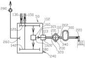
도 1 은 2-행정 내연 피스톤 엔진 (1) 의 실린더 (100) 내로의 기상 연료의 직접 분사를 위한 단순화된 조립체 (50) 를 개략적으로 도시한다. 조립체는 엔진의 하나의 연소 챔버에 직접 기상 연료를 분사하는데 참여하도록 구성되는 반면, 연료는 액상의 분사 압력으로 가압된다. 조립체 (50) 는 서로 평행하게 배열된 액화된 가스 공급 매니폴드 섹션 (120) 및 액화된 가스 복귀 매니폴드 섹션 (140) 을 포함한다. 실제로, 매니폴드 섹션들은 유리하게는 파이프 및 플랜지들을 사용하여 형성된다. 이 경우에, 단어 섹션은 도 1 에서의 조립체가 하나의 실린더에 대한 것이고 일반적으로 엔진은 하나 초과의 실린더들를 갖는다는 사실을 의미한다. 이 경우에, 매니폴드는 플랜지들에 의해 서로 결합된 각각의 수의 매니폴드 섹션들로 형성된다. 도 1 에서의 조립체는 엔진의 하나의 실린더에 대한 연료 전달 라인의 최소 구성요소들을 도시한다. 그리고, 엔진이 차례로 배열된 일렬로 여러 개의 실린더들을 포함할 때, 엔진은 액화된 가스 공급 매니폴드 (120') 및 액화된 가스 복귀 매니폴드 (140') 가 실린더들의 라인의 첫 번째 실린더로부터 실린더들의 라인의 마지막 실린더까지 연장되도록 서로 연결된 대응하는 수의 조립체들 (50) 을 구비한다 (도 3 참조). 액화된 가스 공급 매니폴드 (120') 는 액화된 가스 공급 파이프 (130) 에 연결되고, 액화된 가스 복귀 매니폴드 (140') 는 액화된 가스 복귀 파이프 (150) 에 연결된다.1 schematically shows a
조립체는 액화된 가스 공급 매니폴드 섹션 (120) 및 액화된 가스 복귀 매니폴드 섹션 (140) 에 연결되는 액화된 가스 고압 펌프 유닛 (160) 을 더 포함한다. 액화된 가스는 펌핑 및 주변으로부터의 열전달로 인하여 펌프내에서 가열되는 경향이 있다. 펌프에는 펌핑 스테이지에서 펌프 내의 액화된 가스의 원하지 않는 워밍을 최소화하기 위해 단열재가 제공된다. 펌프에는, 액화된 가스 공급 매니폴드 섹션 (120) 에 대한 연결에 추가하여, 액화된 가스 복귀 매니폴드 섹션 (140) 에 대한 연결이 제공된다. 이는, 펌프에서 기상 형태로 액화된 가스의 부분적인 상변화를 방지하거나 적어도 최소화하기 위해서는 펌프에서 액화된 가스의 온도를 낮게 유지하는 것이 유리하므로, 액화된 가스의 일부를 펌프를 통해 유입시켜 펌프 유닛 (160) 을 냉각하기 위한 액화된 가스 복귀 매니폴드로 복귀시키기 때문이다. 극저온 상태의 액화된 가스는, 액화된 가스 공급 매니폴드 (120) 에서 액화된 가스 고압 펌프 유닛 (160) 으로 유동하는 액화된 가스의 일부를 액화된 가스 복귀 매니폴드 (140) 로 안내하여 액화된 가스의 공급원으로 복귀시킬 수 있도록, 액화된 가스 고압 펌프 유닛 (160) 을 통하여 부분적으로 순환된다. 액화된 가스 공급 매니폴드 (120) 로부터 액화된 가스 고압 펌프 유닛 (160) 으로 유동하는 액화된 가스의 대부분은, 원하는 연료 분사 압력이 되는 상승된 압력에서 액화된 가스 고압 펌프 유닛 (160) 내의 고압 액화된 가스 출구 (180) 로 안내된다. 액화된 가스 고압 펌프 유닛 (160) 은 유압 작동식 피스톤 펌프를 포함하는 것이 바람직하다. 펌프는 고압 유압유에 의하여 구동되어, 유압유가 펌프의 구동 부분 및 피스톤을 왕복이동시키도록 안내되는 구동 부분을 포함한다.The assembly further includes a liquefied gas high
상승된 압력에서 액화된 가스는 고압 액화된 가스 출구 (180) 를 통해, 액화된 가스를 기상 형태로 증발시키고 기상 가스를 엔진으로 부산하기에 적합한 레벨로 가열하도록 구성된 열교환기 유닛 (200) 으로 안내된다. 이를 위해, 열교환기 유닛 (200) 은 고압 액화된 가스 출구 (180) 및 적어도 하나의 가스 연료 분사기 (220) 와 유동 연결된다. 열교환기 유닛 (200) 에는 액화된 가스 입구 (201) 및 기상 가스 출구 (202) 가 제공되며, 액화된 가스 입구는 인클로저 (102) 외부의 연료 공급 라인 (320), 보다 구체적으로는 제 2 연료 공급 라인 (340) 에 의해, 액화된 가스 고압 펌프 유닛 (160) 의 고압 출구에 연결된다.The liquefied gas at elevated pressure is conducted through a high-pressure liquefied
조립체는, 액화된 가스 공급 매니폴드 섹션 (120), 액화된 가스 복귀 매니폴드 섹션 (140) 및 액화된 가스 고압 펌프 유닛 (160) 을 둘러싸는 인클로저 (102) 를 포함한다. 인클로저 (102) 외부의 액화 또는 기상 가스를 포함하는 구성요소들은 가스를 포함하는 내부 공간과 경계를 이루는 이중벽 (110) 내부의 중간 공간을 형성하는 별도의 이중벽 (110) 을 구비한다. 예를 들어, 파이프들은 내부 파이프 외부에 중간 공간을 사이에 두고 다른 파이프를 구비한다. 연료 공급 라인 (320) 의 일부는 인클로저 내부에 있으며 이를 제 1 연료 공급 라인 (321) 이라 할 수 있다. 연료 공급 라인 (320) 의 일부는 인클로저 (102) 외부에 있으며 이를 제 2 연료 공급 라인 (340) 이라 할 수 있다. 제 1 연료 공급 라인 (321) 은 단일벽 파이프로 이루어지고, 제 2 연료 공급 라인 (340) 은 이중벽 파이프로 이루어진다. 조립체는 인클로저의 벽에 관통 블록 (103) 을 포함한다. 관통 블록 (103) 에는 인클로저 (102) 내부의 제 1 연료 공급 라인 (321) 과 인클로저 (102) 외부의 제 2 연료 공급 라인 (340) 이 서로 연결되는 도관 (320') 이 제공된다. 관통 블록 (103) 은 인클로저 (102) 의 공간으로부터 연료 공급 라인 (320) 의 중간 공간을 분리한다. 관통 블록 (103) 은 또한 주변으로부터 인클로저의 내부 공간의 연결을 밀봉한다. 펌프와 분사기 (220) 사이의 고압 라인 (320) 으로부터의 누출은 연료 공급 라인의 그 부분에서 압력이 상당히 높기 때문에, 예를 들어 15 MPa 의 누출에 대한 가장 가능성 있는 지점이다. 제 1 연료 공급 라인 (321) 의 고장의 경우에, 누출은 인클로저 (102) 내로 유동한다. 인클로저 외부에서, 제 2 연료 공급 라인 (340) 의 고장의 경우에, 관통 블록 (103) 에 의해 인클로저 (102) 의 내부 공간과 분리된 라인의 중간 공간내로 누출이 유동한다. 인클로저 내부의 제 1 연료 공급 라인 (321) 의 부분의 체적은 너무 작아서 인클로저 (102) 의 큰 체적은 인클로저의 통기와 함께 누출을 쉽게 처리할 것이다. 누출이 관찰될 때, 그 후 대응하는 펌프는 즉시 차단될 수 있고, 누출된 양은 인클로저 (102) 의 통기 체적에 비해 비교적 작게 유지될 것이다.The assembly includes an
인클로저 내의 액화된 가스를 포함하는 구성요소들은 액화된 가스를 포함하는 내부 공간과 경계를 이루는 단일벽을 구비한다. 인클로저 (102) 외부의 액화 또는 기상 가스를 포함하는 구성요소들의 가스의 누출 가능성이 검출되고 적합하게 취급된다. 제 2 연료 공급 라인 (340) 으로부터 내부 파이프와 외부 파이프 사이의 중간 공간으로 누출된 어떠한 가스는 별도의 배관 (미도시) 에 의해 유도되어 추가 처리될 수 있다. 따라서, 액화된 가스 공급 매니폴드 섹션 (120) 은 단일벽 매니폴드이고, 액화된 가스 복귀 매니폴드 섹션 (140) 은 각각 단일벽 매니폴드이다. 연료 가스는 열교환기 유닛 (200) 에서 증발되기 전까지 액상 상태임을 알아야 한다.Components containing the liquefied gas within the enclosure have a single wall bounding an interior space containing the liquefied gas. Possible leaks of gas from components containing liquefied or gaseous gas outside the
조립체는 엔진의 하나의 실린더에 대한 기상 연료 분사 모듈로서 이용될 수 있고, 다중-실린더 엔진에 적용될 때, 엔진은 그 실린더의 각각의 실린더에 대한 조립체를 구비하며, 조립체의 액화된 가스 공급 매니폴드 섹션들 (120) 은 서로 연결되고, 조립체의 액화된 가스 복귀 매니폴드 섹션들 (140) 은 각각 서로 연결되어 엔진의 실린더들의 라인에서 제 1 실린더로부터 마지막 실린더까지 서로 평행하게 연장되는 매니폴드들을 형성한다.The assembly can be used as a gaseous fuel injection module for one cylinder of an engine, and when applied to a multi-cylinder engine, the engine has an assembly for each cylinder of that cylinder, and a liquefied gas supply manifold of the assembly. The
통기 및 조립체 (50) 의 인클로저 (102) 로부터 멀리 누출될 수 있는 기상 연료의 제거를 용이하게 하기 위해, 조립체 (50) 와 관련하여 배열된 송풍기 (280) 에 연결된 공기 입구 (240) 및 공기 출구 (260) 가 제공된다. 송풍기 (280) 는 인클로저 (102) 에서 원하는 유량 및 저압을 얻도록 적합하게 연결된 하나 또는 여러 개의 송풍기들로 구성될 수 있다. 엔진의 여러 개의 실린더들에 연료 분사를 서빙하기 위해 여러 개의 조립체들이 제공되더라도 하나의 공기 출구만이 필요하다는 점에 유의해야 한다.An
도 2 는 도 1 에 도시된 조립체로부터 추가로 개발된 2-행정 내연 피스톤 엔진의 실린더 (100) 내로 기상 연료의 직접 분사를 위한 조립체 (5) 를 개략적으로 개시한다. 도 1 에서, 가스 공급 라인 (320), 특히 기상 연료를 포함하는 제 2 공급 라인 (340) 의 일부는 연료 축압기로서 작용하기에 적절한 체적을 갖는다. 여기에 도시되지 않더라도, 교환기 유닛 (200) 은 또한 적절한 열원과 관련된다. 조립체는 액화된 가스 연료를 가압 및 증발시키고 기상 연료를 하나의 연소 챔버에 직접 분사하도록 구성된다. 도 2 에 도시된 조립체 (50) 는 그렇지 않으면 도 1 에 도시된 것과 유사하지만, 여기서 조립체는 연료 공급 라인 (320) 에 의해 열교환기 유닛의 기상 가스 출구에 연결된 별개의 기상 가스 축압기 (300) 를 포함한다.FIG. 2 schematically discloses an assembly 5 for direct injection of gaseous fuel into a
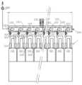
도 3 에는 2-행정, 다중-실린더 내연 피스톤 엔진 (1) 의 실린더에서 기상 연료를 직접 분사하기 위한 조립체를 개시한다. 도 3 에 도시된 대형 2-행정 크로스헤드 엔진은, 라인에 하나 초과, 일반적으로 6 개 초과의 실린더들 (100) 을 포함한다. 본 발명에 따른 기상 연료 공급 시스템이 구체적으로 의도된 대형 2-행정 엔진은, 저속 크로스헤드 엔진이고, 약 50 cm 내지 최대 1 m 인 실린더 보어 직경 및 약 2.5 내지 3.0 미터의 행정 길이를 가진다.3 discloses an assembly for direct injection of gaseous fuel in a cylinder of a two-stroke, multi-cylinder internal
실린더들 (100) 의 각각의 실린더에는 도 2 에 따른 조립체가 제공된다. 도 3 의 실시형태에서, 조립체는 각각의 실린더에 대해 적어도 2 개의 연료 분사기들 (220) 을 포함하며, 이들 연료 분사기 모두는 공유 또는 공통 축압기 (300) 에 연결된다. 예를 들어, 엔진의 동력 및 보어 직경에 따라, 각각의 실린더에 공통 축압기 (300) 에 연결된 3 개의 분사기들을 제공하는 것이 더 유리할 수 있다. 다중-실린더 2-행정 엔진에 적용될 때, 인클로저 (102) 는 엔진의 실린더들 (100) 의 라인의 길이에 실질적으로 대응하는 길이 (L) 를 갖는다. 즉, 인클로저는 엔진 (1) 의 실린더들의 라인의 제 1 실린더로부터 실린더들의 라인의 마지막 실린더까지 연장된다.Each cylinder of the
인클로저 (102) 는 인클로저 (102) 의 반대편 단부들에서 공기 입구 (240) 및 출구 (280) 를 구비한다. 인클로저는 서로 연결된 여러 개의 별개의 섹션으로 형성될 수 있다. 공기 출구 (260) 는 송풍기 (280) 에 연결된다. 하나의 공기 출구만이 필요하지만, 도 2 에 따른 여러 개의 조립체들이 엔진의 여러 개의 실린더들에 연료 분사를 서빙하기 위해 제공되더라도, 하나의 공기 출구 대신에 인클로저에 2 개 또는 심지어 더 많은 출구들이 제공될 수 있다는 것에 유의해야 한다. The
인클로저 (102) 는 액화된 가스 공급 매니폴드 (120') 및 액화된 가스 복귀 매니폴드 (140') 를 전체적으로 또한 액화된 가스 고압 펌프 유닛들 (160) 도 감싼다. 이러한 방식으로, 인클로저 내의 액화된 가스를 포함하는 구성요소들은 액화된 가스를 포함하는 내부 공간 및 공통의 인클로저와 경계를 이루는 단일벽을 구비한다. 따라서, 액화된 가스 공급 매니폴드 (120') 및 각각의 액화된 가스 복귀 매니폴드 (140') 는 단일벽 매니폴드들라고 할 수 있다. 인클로저 (102) 의 외부에 액화 또는 기상 가스를 포함하는 구성요소들은, 또한 가스를 포함하고 가스를 분사기들 (220) 로 전달하는 기상 연료 공급 라인 (320) 과 경계를 이루는 이중벽을 구비한다.The
본 발명은 엔진이 엔진의 실린더들 (100) 의 각각의 실린더에 대해 하나의 연료 전달 라인을 포함하도록 도시될 수 있다. 따라서, 조립체는 엔진의 실린더들을 위한 여러 개의 연료 전달 라인들을 포함하고, 각각의 연료 전달 라인은 액화된 가스 공급 매니폴드 (120') 및 액화된 가스 복귀 매니폴드 (140') 에 연결된 하나의 액화된 가스 고압 펌프 유닛 (160), 액화된 가스를 증발시키고 기상 가스를 가열하도록 구성된 하나의 열교환기 유닛 (200), 및 기상 연료를 수용하기 위해 다수의 연료 분사기들 (220) 이 연결되는 하나의 기상 가스 축압기 (240) 를 포함한다. The invention can be shown such that the engine includes one fuel delivery line for each cylinder of the engine's
액화된 가스 공급 매니폴드 (120') 는, 도 2 에 도시된 바와 같이, 엔진의 각각의 실린더 (100) 에 대해 하나의 공급 매니폴드 섹션을 포함하는 다수의 가스 공급 매니폴드 섹션들 (120) 의 조립체이다. 제각각, 액화된 가스 복귀 매니폴드 (140') 는 엔진의 각각의 실린더에 대해 하나의 복귀 매니폴드 섹션을 포함하는 다수의 가스 복귀 매니폴드 섹션들 (140) 의 조립체이다. 엔진의 모든 실린더들에 대해 서빙하는 액화된 가스 공급 파이프 (130) 및 액화된 가스 복귀 파이프 (150) 가 있다.The liquefied gas supply manifold 120', as shown in FIG. 2, includes a plurality of gas
액화된 가스 공급 매니폴드 (120') 및 액화된 가스 복귀 매니폴드 (140') 뿐만 아니라 액화된 가스 고압 펌프 (160) 유닛들 각각은 공통 인클로저 (102) 및 열교환기 유닛들 (200) 내에 배열되고, 기상 가스 축압기들 (240) 은 인클로저 (102) 외부에 배열된다. 각각의 실린더에 대한 축압기는 각각의 실린더 헤드의 상부에, 분산기들 근처에 설치될 수 있다. 인클로저 (102) 는 안전상의 이유로 제공된다. 인클로저 내의 연료 시스템에 누출이 있다면, 누출된 가스는 송풍기 (280) 에 의한 추가 처리를 위해 멀리 안내될 수 있다. 펌프와 분사기 (220) 사이의 고압 라인으로부터의 누출이 가장 가능성 있는 누출 지점이다. 하나의 단일벽 고압 라인에서의 체적은 너무 작아서, 인클로저 (102) 의 큰 체적 및 그것의 통기는 누출을 쉽게 처리할 것이다. 누출이 관찰될 때, 대응하는 펌프는 즉시 신속하게 차단될 수 있고, 가스의 누출된 양은 인클로저 (102) 의 통기 체적에 비해 비교적 작게 유지될 것이다.The liquefied gas supply manifold 120' and liquefied gas return manifold 140' as well as the liquefied gas high pressure pump 160 units are each arranged within a
도 3 에 도시된 바와 같이, 인클로저 (102), 액화된 가스 공급 매니폴드 (120'), 액화된 가스 복귀 매니폴드 (140') 및 액화된 고압 펌프 유닛 (160) 을 포함하는 조립체는 엔진의 상부에 배열된다. 조립체는 엔진에 부착되는 적절한 지지 구조에 의해 지지된다. 유리하게는, 조립체는 엔진의 실린더 헤드들 위에 배열된다.As shown in FIG. 3, an assembly comprising an
본 발명은 본원에서 현재 가장 바람직한 실시형태들로 고려되는 것과 관련하여 실시예의 방식으로 설명되었지만, 본 발명은 개시된 실시형태들에 제한되는 것이 아니고, 첨부된 청구범위에서 규정된 바와 같이, 본원의 특징들의 다양한 조합들 또는 변경들, 그리고 본 발명의 범위 내에 포함된 여러 개의 다른 적용들을 포함하는 것으로 의도되는 것으로 이해되어야 한다. 상기 임의의 실시형태와 관련하여 언급된 상세한 설명들은 이런 조합들이 기술적으로 실현가능하다면 또 다른 실시형태와 관련하여 사용될 수도 있다.Although the present invention has been described by way of example in relation to what is presently considered the most preferred embodiments herein, the present invention is not limited to the disclosed embodiments, but the features herein set forth in the appended claims. It should be understood that it is intended to cover various combinations or variations of these, and many other applications included within the scope of this invention. Details mentioned in relation to any of the above embodiments may be used in relation to another embodiment if such combinations are technically feasible.
Claims (14)
Translated fromKorean상기 조립체 (50) 는 인클로저 (102) 를 포함하고,
상기 인클로저는,
- 액화된 가스 공급 매니폴드 (120, 120'),
- 액화된 가스 복귀 매니폴드 (140, 140'),
- 상기 액화된 가스 공급 매니폴드 (120, 120') 및 상기 액화된 가스 복귀 매니폴드 (140, 140') 에 연결되는 액화된 가스 고압 펌프 유닛 (160),
- 상기 액화된 가스 고압 펌프 유닛 (160) 에서의 고압 액화된 가스 출구 (180)
를 둘러싸고,
상기 조립체는,
- 액화된 가스를 증발시키도록 구성되고 기상 가스를 가열하며 그리고 액화된 가스 입구 (201) 및 기상 가스 출구 (202) 를 구비하는 열교환기 유닛 (200) 으로서, 상기 액화된 가스 입구 (201) 는 연료 공급 라인 (320) 에 의해 상기 액화된 가스 고압 펌프 유닛 (160) 의 고압 출구 (180) 에 연결되는, 상기 열교환기 유닛 (200), 및
- 상기 열교환기 유닛에 연결된 적어도 하나의 기상 가스 연료 분사기 (220)
를 더 포함하는, 조립체 (5).An assembly (50) for direct injection of gaseous fuel in a cylinder (100) of a two-stroke internal combustion piston engine (1),
the assembly (50) includes an enclosure (102);
The enclosure,
- liquefied gas supply manifolds (120, 120');
- liquefied gas return manifolds (140, 140');
- a liquefied gas high pressure pump unit (160) connected to the liquefied gas supply manifold (120, 120') and to the liquefied gas return manifold (140, 140');
- high pressure liquefied gas outlet 180 from the liquefied gas high pressure pump unit 160
surround,
The assembly is
- a heat exchanger unit (200) configured to evaporate liquefied gas, heats the gaseous gas and has a liquefied gas inlet (201) and a gaseous gas outlet (202), said liquefied gas inlet (201) comprising: The heat exchanger unit 200, which is connected to the high pressure outlet 180 of the liquefied gas high pressure pump unit 160 by a fuel supply line 320, and
- at least one vapor gas fuel injector (220) connected to said heat exchanger unit;
The assembly (5) further comprising a.
상기 인클로저 (102) 는 상기 조립체에 배열된 송풍기 (280) 에 연결가능한 공기 입구 (240) 및 출구 (260) 를 구비하는 것을 특징으로 하는, 조립체 (5).According to claim 1,
The assembly (5), characterized in that the enclosure (102) has an air inlet (240) and an outlet (260) connectable to a blower (280) arranged in the assembly.
상기 인클로저 (102) 내의 상기 액화된 가스 공급 매니폴드 (120, 120') 는 단일벽 매니폴드이고, 상기 인클로저 (102) 내의 상기 액화된 가스 복귀 매니폴드 (140, 140') 는 단일벽 매니폴드인 것을 특징으로 하는, 조립체 (5).According to claim 1 or 2,
The liquefied gas supply manifolds 120, 120' within the enclosure 102 are single-wall manifolds, and the liquefied gas return manifolds 140, 140' within the enclosure 102 are single-wall manifolds. characterized in that the assembly (5).
상기 인클로저 (102) 의 외부의 상기 연료 공급 라인 (320) 에는 이중벽 (110) 내부에 중간 공간을 형성하는 별도의 이중벽 (110) 이 제공되고, 상기 인클로저 (102) 에는 상기 연료 공급 라인 (320) 이 상기 인클로저로부터 상기 열교환기 유닛 (200) 으로 이어지는 관통 블록 (103) 이 제공되며, 상기 관통 블록 (103) 은 상기 인클로저 (102) 의 공간으로부터 상기 연료 공급 라인 (320) 의 중간 공간을 분리하는 것을 특징으로 하는, 조립체 (5).According to any one of claims 1 to 3,
The fuel supply line 320 outside the enclosure 102 is provided with a separate double wall 110 forming an intermediate space inside the double wall 110, and the fuel supply line 320 is provided in the enclosure 102. A pass-through block 103 leading from the enclosure to the heat exchanger unit 200 is provided, and the pass-through block 103 separates the intermediate space of the fuel supply line 320 from the space of the enclosure 102. characterized in that, the assembly (5).
상기 조립체는 상기 연료 공급 라인 (320) 에 의해 상기 열교환기 유닛 (200) 의 상기 기상 가스 출구 (202) 에 연결된 기상 가스 축압기 (300) 를 포함하는 것을 특징으로 하는, 조립체 (5).According to any one of claims 1 to 4,
Assembly (5), characterized in that the assembly comprises a gaseous gas accumulator (300) connected to the gaseous gas outlet (202) of the heat exchanger unit (200) by the fuel supply line (320).
상기 조립체는 인클로저 (102) 를 포함하고, 상기 조립체는 실린더들의 라인에 배열된 여러 개의 실린더들 (100) 을 포함하는 다중-실린더 2-행정 내연 피스톤 엔진 (1) 을 위해 구성되고,
- 상기 인클로저 (102) 는 실린더들의 라인의 길이를 가지며,
- 상기 인클로저 (102) 는 상기 인클로저의 반대편 단부들에서 공기 입구 (240) 및 출구 (260) 를 구비하는 것을 특징으로 하는, 조립체 (5).According to any one of claims 1 to 5,
The assembly comprises an enclosure (102), the assembly being configured for a multi-cylinder two-stroke internal combustion piston engine (1) comprising several cylinders (100) arranged in a line of cylinders,
- the enclosure 102 has the length of a line of cylinders,
- an assembly (5), characterized in that the enclosure (102) has an air inlet (240) and an outlet (260) at opposite ends of the enclosure.
상기 조립체는 실린더들의 라인에 배열된 여러 개의 실린더들 (100) 을 포함하는 다중-실린더 2-행정 내연 피스톤 엔진 (1) 을 위해 구성되며,
- 상기 액화된 가스 공급 매니폴드 (120'), 상기 액화된 가스 복귀 매니폴드 (140') 및 상기 액화된 가스 고압 펌프 유닛 (160) 은 상기 인클로저 내에 배열되고,
- 상기 열교환기 유닛 (200), 및 상기 기상 가스 축압기 (240) 는 상기 인클로저 외부에 배열되는 것을 특징으로 하는, 조립체 (5).According to claim 5,
The assembly is designed for a multi-cylinder two-stroke internal combustion piston engine (1) comprising several cylinders (100) arranged in a line of cylinders,
- the liquefied gas supply manifold (120'), the liquefied gas return manifold (140') and the liquefied gas high pressure pump unit (160) are arranged within the enclosure,
- an assembly (5), characterized in that the heat exchanger unit (200) and the gaseous gas accumulator (240) are arranged outside the enclosure.
상기 액화된 가스 공급 매니폴드 (120') 는, 상기 엔진의 각 실린더 (100) 에 대해 하나의 공급 매니폴드 섹션 (120') 을 포함하는 복수의 가스 공급 매니폴드 섹션들 (120) 의 조립체인 것을 특징으로 하는, 조립체 (5).According to any one of claims 1 to 7,
The liquefied gas supply manifold 120' is an assembly of a plurality of gas supply manifold sections 120 including one supply manifold section 120' for each cylinder 100 of the engine. characterized in that, the assembly (5).
상기 액화된 가스 복귀 매니폴드 (140') 는, 상기 엔진의 각 실린더 (100) 에 대해 하나의 복귀 매니폴드 섹션 (140) 을 포함하는 복수의 가스 복귀 매니폴드 섹션들 (140) 의 조립체인 것을 특징으로 하는, 조립체 (5).According to any one of claims 1 to 8,
wherein the liquefied gas return manifold (140') is an assembly of a plurality of gas return manifold sections (140) including one return manifold section (140) for each cylinder (100) of the engine. Characterized by the assembly (5).
상기 조립체는 상기 엔진의 실린더들을 위한 여러 개의 연료 전달 라인들을 포함하고,
각각의 연료 전달 라인은,
상기 액화된 가스 공급 매니폴드 (120) 및 상기 액화된 가스 복귀 매니폴드 (140) 에 연결되는 하나의 액화된 가스 고압 펌프 유닛 (160),
액화된 가스를 증발시키고 상기 기상 가스를 가열하도록 구성된 하나의 열교환기 유닛 (200), 및
하나의 기상 가스 축압기 (240)
를 포함하는 것을 특징으로 하는, 조립체 (5).According to claim 5,
the assembly includes several fuel delivery lines for the cylinders of the engine;
Each fuel delivery line is
one liquefied gas high pressure pump unit (160) connected to the liquefied gas supply manifold (120) and the liquefied gas return manifold (140);
One heat exchanger unit 200 configured to evaporate liquefied gas and heat the gaseous gas, and
One vapor gas accumulator (240)
characterized in that it comprises an assembly (5).
상기 인클로저는 상기 엔진의 실린더들의 라인의 제 1 실린더 (100) 로부터 상기 엔진의 실린더들의 라인의 마지막 실린더 (100) 까지 연장되는 길이를 갖는 것을 특징으로 하는, 2-행정 내연 피스톤 엔진 (1).According to claim 11,
A two-stroke internal combustion piston engine (1), characterized in that the enclosure has a length extending from the first cylinder (100) of the line of cylinders of the engine to the last cylinder (100) of the line of cylinders of the engine.
상기 인클로저 (102), 상기 액화된 가스 공급 매니폴드 (120), 상기 액화된 가스 복귀 매니폴드 (140) 및 액화된 고압 펌프 유닛들 (160) 은 상기 엔진의 상부에 배열되어 부착되는 것을 특징으로 하는, 2-행정 내연 피스톤 엔진 (1).According to claim 11,
Characterized in that the enclosure (102), the liquefied gas supply manifold (120), the liquefied gas return manifold (140) and the liquefied high-pressure pump units (160) are arranged and attached to the top of the engine. , a two-stroke internal combustion piston engine (1).
상기 엔진은 상기 엔진의 각 실린더들 (100) 에 대해 하나의 연료 전달 라인을 포함하는 것을 특징으로 하는, 2-행정 내연 피스톤 엔진 (1).According to claims 12 and 10,
A two-stroke internal combustion piston engine (1), characterized in that the engine comprises one fuel delivery line for each of the cylinders (100) of the engine.
Applications Claiming Priority (1)
| Application Number | Priority Date | Filing Date | Title |
|---|---|---|---|
| PCT/EP2021/051844WO2022161601A1 (en) | 2021-01-27 | 2021-01-27 | An assembly for direct injection of gaseous fuel in a cylinder of a two-stroke internal combustion piston engine and a two-stroke internal com-bustion piston engine |
Publications (2)
| Publication Number | Publication Date |
|---|---|
| KR20230119007Atrue KR20230119007A (en) | 2023-08-14 |
| KR102848472B1 KR102848472B1 (en) | 2025-08-20 |
Family
ID=74347101
Family Applications (1)
| Application Number | Title | Priority Date | Filing Date |
|---|---|---|---|
| KR1020237024760AActiveKR102848472B1 (en) | 2021-01-27 | 2021-01-27 | Two-stroke internal combustion piston engine and assembly for direct injection of gaseous fuel into the cylinder of a two-stroke internal combustion piston engine |
Country Status (6)
| Country | Link |
|---|---|
| EP (1) | EP4285013B1 (en) |
| JP (1) | JP7661655B2 (en) |
| KR (1) | KR102848472B1 (en) |
| CN (1) | CN117203417A (en) |
| DK (1) | DK4285013T3 (en) |
| WO (1) | WO2022161601A1 (en) |
Citations (4)
| Publication number | Priority date | Publication date | Assignee | Title |
|---|---|---|---|---|
| US6095101A (en)* | 1997-01-29 | 2000-08-01 | Man B&W Diesel A/S | Internal combustion engine of the diesel type for combustion of gas, and a method of supplying such an engine with fuel |
| JP2016037935A (en)* | 2014-08-08 | 2016-03-22 | 川崎重工業株式会社 | Gas supply system and vessel mounted with the same |
| JP2016173101A (en)* | 2015-02-10 | 2016-09-29 | マン ディーゼル アンド ターボ フィリアル エーエフ マン ディーゼル アンド ターボ エスイー ティスクランド | Fuel gas supply system for internal combustion engine |
| WO2018202313A1 (en)* | 2017-05-05 | 2018-11-08 | Wärtsilä Finland Oy | A liquefied gas fuel feeding system and a marine vessel |
Family Cites Families (7)
| Publication number | Priority date | Publication date | Assignee | Title |
|---|---|---|---|---|
| US6659730B2 (en)* | 1997-11-07 | 2003-12-09 | Westport Research Inc. | High pressure pump system for supplying a cryogenic fluid from a storage tank |
| JP4570130B2 (en)* | 2004-04-23 | 2010-10-27 | 岩谷産業株式会社 | Equipment-linked low temperature liquefied gas supply equipment |
| KR101529841B1 (en) | 2011-11-11 | 2015-06-17 | 도요타지도샤가부시키가이샤 | Hybrid drive system |
| US9188069B2 (en) | 2012-12-27 | 2015-11-17 | Caterpillar Inc. | Gaseous fuel system, direct injection gas engine system, and method |
| KR101606701B1 (en) | 2014-08-18 | 2016-03-28 | 대우조선해양 주식회사 | Container Ship And Arrangement Method Of The Same |
| DK179056B1 (en) | 2016-05-26 | 2017-09-25 | Man Diesel & Turbo Filial Af Man Diesel & Turbo Se Tyskland | Fuel supply system for a large two-stroke compression-ignited high-pressure gas injection internal combustion engine |
| DE102019205605A1 (en)* | 2019-04-17 | 2020-10-22 | Robert Bosch Gmbh | Fuel delivery device for cryogenic fuels, fuel system with a fuel delivery device |
- 2021
- 2021-01-27JPJP2023545341Apatent/JP7661655B2/enactiveActive
- 2021-01-27EPEP21702258.1Apatent/EP4285013B1/enactiveActive
- 2021-01-27KRKR1020237024760Apatent/KR102848472B1/enactiveActive
- 2021-01-27CNCN202180091079.1Apatent/CN117203417A/enactivePending
- 2021-01-27WOPCT/EP2021/051844patent/WO2022161601A1/ennot_activeCeased
- 2021-01-27DKDK21702258.1Tpatent/DK4285013T3/enactive
Patent Citations (4)
| Publication number | Priority date | Publication date | Assignee | Title |
|---|---|---|---|---|
| US6095101A (en)* | 1997-01-29 | 2000-08-01 | Man B&W Diesel A/S | Internal combustion engine of the diesel type for combustion of gas, and a method of supplying such an engine with fuel |
| JP2016037935A (en)* | 2014-08-08 | 2016-03-22 | 川崎重工業株式会社 | Gas supply system and vessel mounted with the same |
| JP2016173101A (en)* | 2015-02-10 | 2016-09-29 | マン ディーゼル アンド ターボ フィリアル エーエフ マン ディーゼル アンド ターボ エスイー ティスクランド | Fuel gas supply system for internal combustion engine |
| WO2018202313A1 (en)* | 2017-05-05 | 2018-11-08 | Wärtsilä Finland Oy | A liquefied gas fuel feeding system and a marine vessel |
Also Published As
| Publication number | Publication date |
|---|---|
| WO2022161601A1 (en) | 2022-08-04 |
| JP2024505039A (en) | 2024-02-02 |
| EP4285013B1 (en) | 2025-03-26 |
| KR102848472B1 (en) | 2025-08-20 |
| CN117203417A (en) | 2023-12-08 |
| DK4285013T3 (en) | 2025-06-10 |
| EP4285013A1 (en) | 2023-12-06 |
| JP7661655B2 (en) | 2025-04-15 |
Similar Documents
| Publication | Publication Date | Title |
|---|---|---|
| KR101913005B1 (en) | Vessel having Gas Treatment System | |
| EP2622190B1 (en) | Two engine system with a gaseous fuel stored in liquefied form | |
| JP7132284B2 (en) | Large 2-stroke uniflow scavenging gas fuel engine | |
| KR102487243B1 (en) | Ventilation System and Vessel having the same | |
| EP0069717A1 (en) | Method for utilizing boil-off gas from cryogenic liquids as fuel in a dual gas/oil-burning diesel engine, and a system for utilizing the method | |
| JP2009541140A (en) | Gas powered marine fuel system | |
| JP6482596B2 (en) | Fuel supply system for large two-stroke compression ignition high pressure gas injection internal combustion engine | |
| JP2019504792A (en) | Ship with gas revaporization system | |
| JP6650003B2 (en) | Large 2-stroke compression ignition internal combustion engine with dual fuel system | |
| US12172513B2 (en) | Gas tank arrangement | |
| KR101622754B1 (en) | An internal combustion engine, and a method of supplying such engine with gaseous fuel | |
| KR102848472B1 (en) | Two-stroke internal combustion piston engine and assembly for direct injection of gaseous fuel into the cylinder of a two-stroke internal combustion piston engine | |
| US10774820B2 (en) | Cryogenic pump | |
| JP6461541B2 (en) | Ship | |
| KR102807206B1 (en) | Direct injection gaseous fuel supply system for two-stroke internal combustion piston engine, two-stroke internal combustion piston engine and method of operating a two-stroke internal combustion piston engine | |
| JP2022126753A (en) | Gas fuel supply system and method for operating gas fuel supply system | |
| KR101643038B1 (en) | A Treatment System of Liquefied Gas |
Legal Events
| Date | Code | Title | Description |
|---|---|---|---|
| A201 | Request for examination | ||
| E13-X000 | Pre-grant limitation requested | St.27 status event code:A-2-3-E10-E13-lim-X000 | |
| PA0105 | International application | St.27 status event code:A-0-1-A10-A15-nap-PA0105 | |
| PA0201 | Request for examination | St.27 status event code:A-1-2-D10-D11-exm-PA0201 | |
| P11-X000 | Amendment of application requested | St.27 status event code:A-2-2-P10-P11-nap-X000 | |
| P13-X000 | Application amended | St.27 status event code:A-2-2-P10-P13-nap-X000 | |
| P11-X000 | Amendment of application requested | St.27 status event code:A-2-2-P10-P11-nap-X000 | |
| P13-X000 | Application amended | St.27 status event code:A-2-2-P10-P13-nap-X000 | |
| PG1501 | Laying open of application | St.27 status event code:A-1-1-Q10-Q12-nap-PG1501 | |
| E902 | Notification of reason for refusal | ||
| PE0902 | Notice of grounds for rejection | St.27 status event code:A-1-2-D10-D21-exm-PE0902 | |
| P11-X000 | Amendment of application requested | St.27 status event code:A-2-2-P10-P11-nap-X000 | |
| PE0701 | Decision of registration | St.27 status event code:A-1-2-D10-D22-exm-PE0701 | |
| PR0701 | Registration of establishment | St.27 status event code:A-2-4-F10-F11-exm-PR0701 | |
| PR1002 | Payment of registration fee | St.27 status event code:A-2-2-U10-U12-oth-PR1002 Fee payment year number:1 | |
| PG1601 | Publication of registration | St.27 status event code:A-4-4-Q10-Q13-nap-PG1601 |