KR20230118282A - measuring and holding apparatus for occlusal vertical dimension - Google Patents
measuring and holding apparatus for occlusal vertical dimensionDownload PDFInfo
- Publication number
- KR20230118282A KR20230118282AKR1020220014651AKR20220014651AKR20230118282AKR 20230118282 AKR20230118282 AKR 20230118282AKR 1020220014651 AKR1020220014651 AKR 1020220014651AKR 20220014651 AKR20220014651 AKR 20220014651AKR 20230118282 AKR20230118282 AKR 20230118282A
- Authority
- KR
- South Korea
- Prior art keywords
- vertical
- holder
- arch
- measuring
- handle body
- Prior art date
- Legal status (The legal status is an assumption and is not a legal conclusion. Google has not performed a legal analysis and makes no representation as to the accuracy of the status listed.)
- Granted
Links
Images


Classifications
- A—HUMAN NECESSITIES
- A61—MEDICAL OR VETERINARY SCIENCE; HYGIENE
- A61C—DENTISTRY; APPARATUS OR METHODS FOR ORAL OR DENTAL HYGIENE
- A61C19/00—Dental auxiliary appliances
- A61C19/04—Measuring instruments specially adapted for dentistry
- A—HUMAN NECESSITIES
- A61—MEDICAL OR VETERINARY SCIENCE; HYGIENE
- A61C—DENTISTRY; APPARATUS OR METHODS FOR ORAL OR DENTAL HYGIENE
- A61C11/00—Dental articulators, i.e. for simulating movement of the temporo-mandibular joints; Articulation forms or mouldings
- A61C11/02—Dental articulators, i.e. for simulating movement of the temporo-mandibular joints; Articulation forms or mouldings characterised by the arrangement, location or type of the hinge means ; Articulators with pivots
- A—HUMAN NECESSITIES
- A61—MEDICAL OR VETERINARY SCIENCE; HYGIENE
- A61C—DENTISTRY; APPARATUS OR METHODS FOR ORAL OR DENTAL HYGIENE
- A61C11/00—Dental articulators, i.e. for simulating movement of the temporo-mandibular joints; Articulation forms or mouldings
- A61C11/08—Dental articulators, i.e. for simulating movement of the temporo-mandibular joints; Articulation forms or mouldings with means to secure dental casts to articulator
- A—HUMAN NECESSITIES
- A61—MEDICAL OR VETERINARY SCIENCE; HYGIENE
- A61C—DENTISTRY; APPARATUS OR METHODS FOR ORAL OR DENTAL HYGIENE
- A61C19/00—Dental auxiliary appliances
- A61C19/04—Measuring instruments specially adapted for dentistry
- A61C19/05—Measuring instruments specially adapted for dentistry for determining occlusion
Landscapes
- Health & Medical Sciences (AREA)
- Life Sciences & Earth Sciences (AREA)
- General Health & Medical Sciences (AREA)
- Oral & Maxillofacial Surgery (AREA)
- Dentistry (AREA)
- Epidemiology (AREA)
- Animal Behavior & Ethology (AREA)
- Public Health (AREA)
- Veterinary Medicine (AREA)
- Biomedical Technology (AREA)
- Biophysics (AREA)
- Engineering & Computer Science (AREA)
- Dental Tools And Instruments Or Auxiliary Dental Instruments (AREA)
Abstract
Translated fromKoreanDescription
Translated fromKorean본 발명은 수직고경 측정 및 유지 장치에 관한 것으로, 보다 상세하게는 호환성 및 작업편의성이 개선되는 수직고경 측정 및 유지 장치에 관한 것이다.The present invention relates to a vertical height measuring and maintaining device, and more particularly, to a vertical height measuring and maintaining device having improved compatibility and work convenience.
일반적으로 의치(denture)는 결손된 치아를 대체할 외형과 기능을 인공적으로 회복시켜주는 구강 내 인공치주조직을 의미한다.In general, denture refers to artificial periodontal tissue in the oral cavity that artificially restores appearance and function to replace missing teeth.
상기 의치는 구강에 설치되어 저작기능을 회복시키고 대합치 또는 상기 의치가 필요한 대상악궁측 잔존치아 및 치조골의 변형 또는 손상을 방지하는 것으로, 구강에 끼웠다 분리할 수 있는 형태의 틀니 또는 소수의 임플란트를 식립 후 고정시키는 오버덴쳐 등이 상기 의치에 포함될 수 있다.The dentures are installed in the oral cavity to restore the masticatory function and prevent deformation or damage of the opposing teeth or the remaining teeth and alveolar bone on the target arch side that require the dentures. An overdenture for fixing after placement may be included in the denture.
한편, 상기 의치는 환자 개개인에게 적합하게 설계되어야 하며, 설계정보를 기반으로 제조된 의치를 정확한 위치에 설치하기 위해서는 정밀한 구강 정보가 필요하다. 이를 위해, 구강의 표면정보 및 치조골 형상/골밀도 등과 같은 내부 조직정보가 함께 요구된다. 따라서, 환자의 상악 및 하악에 대한 스캔이미지 및 CT이미지를 획득하고 이를 수직고경에 대응하여 정렬 및 정합하는 영상정합 과정이 필요하다.On the other hand, the dentures must be designed to suit each patient, and precise oral information is required to install the dentures manufactured based on the design information in an accurate position. To this end, internal tissue information such as oral surface information and alveolar bone shape/bone density are required together. Therefore, an image matching process is required to acquire scan images and CT images of the upper and lower jaws of the patient, and align and match them according to the vertical dimension.
그러나, 상하악 중 적어도 어느 일측이 완전무치악 또는 부분무치악인 경우, 환자의 정확한 수직고경을 산출하기 어렵다. 따라서, 상기 스캔이미지 및 상기 CT이미지를 상기 수직고경에 대응하여 정렬 및 정합하기 위해서, 상기 수직고경을 정확하게 산출하는 과정이 수행된다.However, when at least one side of the upper and lower jaws is completely edentulous or partially edentulous, it is difficult to accurately calculate the vertical dimension of the patient. Accordingly, in order to align and match the scan image and the CT image corresponding to the vertical height, a process of accurately calculating the vertical height is performed.
상세히, 종래에는 환자의 구강에 대한 인상을 채득하고, 채득된 인상으로 석고모형을 제조한 후 상기 석고모형을 교합기를 이용하여 간격을 조절하면서 수직고경을 산출하였다. 그러나, 이러한 방법은 그 과정이 복잡하며, 수직고경이 환자의 구강에 직접 산출되는 것이 아니기 때문에 정밀도가 저하되는 문제점이 있었다.In detail, in the prior art, an impression of the patient's oral cavity was taken, a plaster cast was manufactured using the obtained impression, and then the vertical diameter of the plaster cast was calculated using an articulator while adjusting the spacing. However, this method has a problem in that the process is complicated and the accuracy is lowered because the vertical dimension is not directly calculated in the oral cavity of the patient.
또한, 상기 석고모형을 통한 상하악의 수직적 교합관계만 고려되므로, 저작과정에서 턱관절의 수평적 움직임에 대한 정보가 상기 의치의 제조과정에 고려되지 못하는 문제점이 있었다. 이로 인해, 최종 제조된 의치를 구강에 설치하여 사용시 불편감이 가중되며 대합치에 불필요한 압력이 가해짐으로 인하여 대합치의 손상 및 턱관절 손상까지 야기하는 문제점이 있었다.In addition, since only the vertical occlusion relationship of the upper and lower jaws is considered through the plaster model, information on the horizontal movement of the temporomandibular joint during the chewing process is not considered in the manufacturing process of the dentures. For this reason, when the finally manufactured denture is installed in the oral cavity and used, discomfort is increased, and unnecessary pressure is applied to the antagonist, resulting in damage to the antagonist and damage to the temporomandibular joint.
한편, 일부에서는 딱딱한 재질로 제조되는 트레이에 묘기침 및 묘기판을 고정시켜 중심위 및 수직고경을 산출한 후 인상채득을 하는 기술이 개시되었다. 이러한 종래의 기술은 상기 트레이의 물성 및 그 두께로 인하여 상하악의 교합시 턱관절과 인접한 구치측에서 상하측 트레이 간의 간섭이 발생한다. 이로 인해, 정확한 수직고경을 산출하기 어려운 문제점이 있었다.On the other hand, in some cases, a technique for taking impressions after calculating centric circumference and vertical diameter by fixing a trick needle and a trick board to a tray made of a hard material has been disclosed. In this conventional technique, interference between the upper and lower trays occurs at the posterior side adjacent to the temporomandibular joint during occlusion of the upper and lower jaw due to the physical properties and thickness of the tray. For this reason, there is a problem in that it is difficult to calculate an accurate vertical height.
이러한 간섭문제를 해결하기 위하여 상기 트레이가 전치측과 구치측으로 분할된 장치가 일부 개시되는데, 이 역시 상기 중심위 및 상기 수직고경을 산출한 후 상기 인상채득이 수행된다. 즉, 전치측 트레이에 상기 묘기침 및 상기 묘기판을 결합시켜 상기 중심위 및 상기 수직고경을 산출한다. 그리고, 상기 수직고경에 맞게 조절된 상기 전치측 트레이를 구강으로부터 분리하고 상기 전치측 트레이에 구치측 트레이를 조립한 후 다시 구강에 인입시켜 상하악의 인상을 채득한다.In order to solve this interference problem, a device in which the tray is divided into an anterior tooth side and a posterior tooth side is partially disclosed, and the impression taking is also performed after calculating the centric relation and the vertical dimension. That is, the centroid and the vertical height are calculated by combining the trick needle and the trick board with the anterior tray. In addition, the anterior tray adjusted to the vertical diameter is separated from the oral cavity, the posterior tray is assembled to the anterior tray, and then inserted into the oral cavity again to obtain an impression of the upper and lower jaw.
그러나, 상기 수직고경을 산출하는 과정과 상기 인상을 채득하는 과정이 실질적으로 별도의 공정으로 진행된다. 이로 인해, 각 공정이 진행되는 과정에서 상당한 시간이 소요되고 작업이 번거로운 문제점이 있었다. 또한, 환자마다 치열궁의 크기가 상이하기 때문에 상기 트레이를 호환 적용하기 어려운 문제점이 있었다.However, the process of calculating the vertical height and the process of obtaining the impression are substantially performed as separate processes. Due to this, there was a problem in that a considerable amount of time was taken and the work was cumbersome in the course of each process. In addition, since the sizes of dental arches are different for each patient, there is a problem in that it is difficult to apply the trays interchangeably.
상기와 같은 문제점을 해결하기 위하여, 본 발명은 호환성 및 작업편의성이 개선되는 수직고경 측정 및 유지 장치를 제공하는 것을 해결과제로 한다.In order to solve the above problems, an object of the present invention is to provide a vertical diameter measuring and maintaining device with improved compatibility and work convenience.
상기의 과제를 해결하기 위하여, 본 발명은 양측에 중앙부를 기준으로 상호 대칭 정렬되는 한쌍의 힌지연결부가 구비되는 핸들몸체부; 한쌍으로 구비되어 각 상기 힌지연결부에 각 후방부가 힌지 연결되며, 전단부가 대상악궁의 너비에 대응되는 간격을 두고 상기 힌지연결부를 중심으로 수평 회전되어 상호 이격되도록 각 상기 후방부로부터 각각 일체로 전향 연장되고, 각 상기 전단부에 착탈결합부가 일체로 돌출 형성되는 홀더부; 및 각 상기 착탈결합부에 외주가 선택적으로 착탈 결합되되 일단부에 대합악궁의 구치측에 대향 밀착되도록 대합형합면부가 형성되며 타단부 중앙으로부터 나사회전홈이 일측방향으로 함몰 형성되는 형합고정부와, 선택적으로 회전되며 승강되도록 상기 나사회전홈에 나사 결합되는 회전체결부가 구비되며 상기 회전체결부의 단부에 상기 대상악궁의 구치측에 대향 밀착되도록 대상형합면부가 형성되는 높이조절부를 포함하는 수직고경 측정유지부를 포함하는 수직고경 측정 및 유지 장치를 제공한다.In order to solve the above problems, the present invention is a handle body portion provided with a pair of hinge connection portions mutually symmetrically aligned with respect to the central portion on both sides; Provided as a pair, each rear part is hingedly connected to each of the hinge connection parts, and the front ends are horizontally rotated around the hinge connection part at intervals corresponding to the width of the target arch, so that they are spaced apart from each other. And, the holder portion in which the detachable coupling portion is integrally formed to protrude from each of the front ends; And the outer periphery is selectively detachably coupled to each of the detachable coupling parts, but at one end, a mating face portion is formed so as to be in close contact with the molar side of the opposing arch, and a screw rotation groove is formed in one direction from the center of the other end. , Vertical height including a height adjustment unit having a rotational fastening portion screwed into the screw rotation groove so as to be selectively rotated and lifted, and an object-shaped joint portion formed so as to be in close contact with the molar side of the target arch at the end of the rotational fastening portion. An apparatus for measuring and maintaining a vertical diameter including a measuring and holding unit is provided.
여기서, 상기 형합고정부의 외주에는 원주방향을 따라 반경방향 내측으로 함몰외주부가 함몰 형성되며, 상기 착탈결합부는 각 상기 홀더부의 전단부 양측으로부터 전향 돌출되되, 각 상기 착탈결합부의 전단부가 상호 대향되는 방향으로 굴곡지게 연장되며 상호간 대향 이격 배치되며 상기 함몰외주부를 감싸며 선택적으로 탄발 결합되고, 상기 착탈결합부에는 상기 함몰외주부의 외면 윤곽에 대응되는 윤곽으로 라운드진 착탈홈부가 전단 중앙으로부터 후향 함몰 형성됨이 바람직하다.Here, the outer circumference of the mold fixing part is recessed inward in the radial direction along the circumferential direction, and the detachable coupling part protrudes forward from both sides of the front end of each holder part, and the front ends of each detachable coupling part are opposite to each other It extends curvedly in the direction, is spaced apart from each other, and is selectively elastically coupled while surrounding the outer circumference of the depression, and in the detachable coupling part, a detachable groove rounded with a contour corresponding to the outer contour of the outer circumference of the depression is recessed backward from the center of the front end. desirable.
이때, 상기 형합고정부의 타단부에는 원주방향을 따라 반경방향 외측으로 돌출되는 걸림단턱이 형성되고, 상기 함몰외주부는 상기 대합형합면부 및 상기 걸림단턱 사이에 형성됨이 바람직하다.At this time, it is preferable that a hooking step protruding outward in a radial direction along the circumferential direction is formed at the other end of the mold fixing part, and the recessed outer periphery is formed between the mating surface and the hooking step.
그리고, 각 상기 홀더부의 후방부는 상기 힌지연결부 및 상기 핸들몸체부 사이에 배치되되, 상기 힌지연결부는 각 상기 홀더부를 회전 가압하여 각 상기 홀더부가 가고정되도록 각 상기 홀더부의 후방부 및 상기 핸들몸체부에 힌지 연결됨이 바람직하다.In addition, the rear part of each holder part is disposed between the hinge connection part and the handle body part, and the hinge connection part rotates and presses each holder part so that each holder part is temporarily fixed. Each of the holder part rear part and the handle body part It is preferably hinged to.
또한, 상기 핸들몸체부의 후단부 중앙에 전향 함몰 형성되는 핸들체결홈에 선택적으로 착탈 결합되는 핸들그립부와, 상기 핸들몸체부 및 상기 핸들그립부 사이에 배치되되 상호 직교되며 수평방향 및 상하방향으로 각각 연장되는 수평정렬바 및 수직정렬바를 더 포함함이 바람직하다.In addition, a handle grip portion selectively detachably coupled to a handle fastening groove formed in a forward depression at the center of the rear end of the handle body portion, and disposed between the handle body portion and the handle grip portion, are orthogonal to each other, and extend horizontally and vertically, respectively. It is preferable to further include a horizontal alignment bar and a vertical alignment bar.
그리고, 각 상기 홀더부는 길이방향 중앙부 일측이 절곡지게 형성되되, 각 상기 홀더부의 전단부는 각 상기 홀더부의 후단부보다 상기 핸들몸체부의 폭방향 양측으로 배치되고, 상기 대합형합면부 및 상기 대상형합면부는 폭방향 양측으로 갈수록 상기 대합악궁의 구치측 및 상기 대상악궁의 구치측을 감싸는 일측방향 및 타측방향으로 각각 굴곡지게 연장 형성됨이 바람직하다.In addition, each of the holder parts is formed such that one side of the central part in the longitudinal direction is bent, and the front end of each holder part is disposed on both sides of the handle body in the width direction of the rear end of each holder part, and the counter-type mating surface part and the counter-type mating surface part It is preferable that each curvedly extends in one direction and the other direction surrounding the molar side of the arch and the molar side of the target arch as it goes to both sides in the width direction.
상기의 해결 수단을 통하여, 본 발명은 다음과 같은 효과를 제공한다.Through the above solution, the present invention provides the following effects.
첫째, 한쌍의 홀더부 전단부에 형성된 착탈결합부에 착탈된 높이 조절이 가능한 각 수직고경 측정유지부가 치열궁의 구치측 너비에 대응되는 간격을 두고 벌어지며 이격되도록 홀더부가 회전 조절된 후 가고정되므로 수직고경 측정의 호환성 및 작업편의성이 현저히 개선될 수 있다.First, each height-adjustable vertical diameter measurement holding part detachable from the detachable coupling part formed at the front end of the pair of holder parts is rotated and fixed so that the holder part is rotated and spaced apart at intervals corresponding to the width of the posterior teeth of the dental arch. The compatibility and work convenience of vertical diameter measurement can be remarkably improved.
둘째, 각 수직고경 측정유지부가 구치측에 고정되어 수직고경이 획득 및 유지된 상태에서, 홀더부 및 핸들몸체부를 수직고경 측정유지부로부터 간편하게 탄발 착탈 가능하므로 3차원 이미지 스캐닝시 수직고경 측정유지부가 용이하게 노출되어 수직고경 측정용이성이 개선되고 제조되는 보철물의 제조정밀성이 개선될 수 있다.Second, each vertical dimension measurement holding part is fixed to the posterior tooth side, and in a state where the vertical height is acquired and maintained, the holder part and the handle body part can be easily attached and detached from the vertical height measurement holding part, so that the vertical height measurement holding part during 3D image scanning It is easily exposed, so the ease of measuring the vertical dimension can be improved, and the manufacturing precision of the prosthesis to be manufactured can be improved.
셋째, 착탈결합부는 수직고경 측정유지부에 함몰된 함몰외주부를 감싸도록 전향 돌출 형성되되, 착탈결합부의 전단 중앙으로부터 착탈홈부가 함몰외주부의 외면 윤곽에 대응되는 윤곽으로 라운드지게 후향 함몰 형성되어 함몰외주부에 선택적으로 형합됨에 따라 구강 배치시 견고한 지지력을 제공할 수 있다.Third, the detachable coupling part is formed in a forward protrusion so as to surround the outer circumference of the depression recessed in the vertical diameter measurement holding unit, and the detachable coupling part is formed with a backward depression in a round shape corresponding to the outer contour of the outer circumference of the depression from the center of the front end of the detachable coupling part. As it is selectively molded to, it can provide a solid support force when placed in the oral cavity.
넷째, 상호 직교되며 수평 및 상하로 연장되는 수평정렬바 및 수직정렬바가 핸들몸체부 및 핸들그립부 사이에 선택적으로 착탈 결합되므로 정중선 및 교합평면이 정확하게 정렬된 상태에서 수직고경 측정유지부가 대상악궁 및 대합악궁 구치측 사이에 정밀하게 고정되므로 최종 보철물의 제조정밀성이 현저히 개선될 수 있다.Fourth, since the horizontal alignment bar and the vertical alignment bar, which are orthogonal to each other and extend horizontally and vertically, are selectively detachable and detachable between the handle body and the handle grip, the vertical dimension measurement holding unit maintains the target arch and the opposing arch while the midline and occlusal plane are accurately aligned. Since it is precisely fixed between the posterior teeth of the arch, the manufacturing precision of the final prosthesis can be remarkably improved.
도 1은 본 발명의 일실시예에 따른 수직고경 측정 및 유지 장치를 나타낸 사시도.
도 2는 본 발명의 일실시예에 따른 수직고경 측정 및 유지 장치에서 수직고경 측정유지부가 제외된 상태를 나타낸 상면도.
도 3은 본 발명의 일실시예에 따른 수직고경 측정 및 유지 장치에서 힌지연결부의 결합상태를 나타낸 단면도.
도 4는 본 발명의 일실시예에 따른 수직고경 측정 및 유지 장치에서 수직고경 측정유지부를 나타낸 사시도.
도 5는 본 발명의 일실시예에 따른 수직고경 측정 및 유지 장치에서 수직고경 측정유지부를 나타낸 정면도.
도 6은 본 발명의 일실시예에 따른 수직고경 측정 및 유지 장치에서 수직고경 측정유지부를 나타낸 단면도.
도 7은 본 발명의 일실시예에 따른 수직고경 측정 및 유지 장치에서 수직고경 측정유지부의 변형예를 나타낸 사시도.
도 8은 본 발명의 일실시예에 따른 수직고경 측정 및 유지 장치에서 수직고경 측정유지부의 변형예를 나타낸 단면도.
도 9 및 도 10 및 도 11은 본 발명의 일실시예에 따른 수직고경 측정 및 유지 장치에서 수직고경 측정유지부의 사용상태를 나타낸 사용예시도.1 is a perspective view showing an apparatus for measuring and maintaining a vertical diameter according to an embodiment of the present invention;
2 is a top view showing a state in which a vertical diameter measuring and maintaining unit is excluded from the vertical diameter measuring and maintaining apparatus according to an embodiment of the present invention;
Figure 3 is a cross-sectional view showing a coupled state of the hinge connection portion in the vertical diameter measuring and maintaining device according to an embodiment of the present invention.
4 is a perspective view illustrating a vertical diameter measuring and holding unit in the vertical diameter measuring and maintaining device according to an embodiment of the present invention;
5 is a front view showing a vertical height measurement and holding unit in the vertical dimension measuring and maintaining device according to an embodiment of the present invention;
6 is a cross-sectional view showing a vertical diameter measuring and holding unit in the vertical diameter measuring and maintaining device according to an embodiment of the present invention.
7 is a perspective view illustrating a modified example of a vertical diameter measuring and maintaining unit in the vertical diameter measuring and maintaining device according to an embodiment of the present invention;
8 is a cross-sectional view showing a modified example of a vertical diameter measuring and maintaining unit in the vertical diameter measuring and maintaining device according to an embodiment of the present invention.
9, 10 and 11 are examples of use of a vertical diameter measuring and maintaining unit in a vertical diameter measuring and maintaining device according to an embodiment of the present invention.
이하, 첨부된 도면을 참조하여 본 발명의 바람직한 실시예에 따른 수직고경 측정 및 유지 장치를 상세히 설명한다.Hereinafter, an apparatus for measuring and maintaining a vertical height according to a preferred embodiment of the present invention will be described in detail with reference to the accompanying drawings.
도 1은 본 발명의 일실시예에 따른 수직고경 측정 및 유지 장치를 나타낸 사시도이고, 도 2는 본 발명의 일실시예에 따른 수직고경 측정 및 유지 장치에서 수직고경 측정유지부가 제외된 상태를 나타낸 상면도이다. 그리고, 도 3은 본 발명의 일실시예에 따른 수직고경 측정 및 유지 장치에서 힌지연결부의 결합상태를 나타낸 단면도이며, 도 4는 본 발명의 일실시예에 따른 수직고경 측정 및 유지 장치에서 수직고경 측정유지부를 나타낸 사시도이다. 그리고, 도 5는 본 발명의 일실시예에 따른 수직고경 측정 및 유지 장치에서 수직고경 측정유지부를 나타낸 정면도이고, 도 6은 본 발명의 일실시예에 따른 수직고경 측정 및 유지 장치에서 수직고경 측정유지부를 나타낸 단면도이다.1 is a perspective view showing an apparatus for measuring and maintaining a vertical diameter according to an embodiment of the present invention, and FIG. 2 is a perspective view showing a vertical diameter measuring and maintaining apparatus in accordance with an embodiment of the present invention without a vertical diameter measuring and maintaining unit. It is a top view. And, Figure 3 is a cross-sectional view showing the coupling state of the hinge connection in the vertical diameter measuring and maintaining device according to an embodiment of the present invention, Figure 4 is the vertical diameter in the vertical diameter measuring and maintaining device according to an embodiment of the present invention It is a perspective view showing the measurement holding part. 5 is a front view showing a vertical diameter measurement and holding unit in the vertical dimension measuring and maintaining device according to an embodiment of the present invention, and FIG. 6 is a vertical dimension measurement in the vertical dimension measuring and maintaining device according to an embodiment of the present invention. A cross-sectional view showing the holding part.
도 1 내지 도 6에서 보는 바와 같이, 본 발명의 일실시예에 따른 수직고경 측정 및 유지 장치(100)는 핸들몸체부(10), 홀더부(20) 및 수직고경 측정유지부(30)를 포함하여 구비된다.As shown in FIGS. 1 to 6, the vertical diameter measuring and maintaining
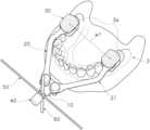
이때, 본 발명은 특히 상악 및 하악 중 적어도 어느 일측의 자연치아 소실량이 많아 수직고경(occlusal vertical dimension,VD)의 산출이 어려운 무치악 또는 부분무치악 환자의 임플란트 식립시 사용될 수 있다.At this time, the present invention can be particularly used when placing an implant in an edentulous or partially edentulous patient, for whom calculation of the vertical dimension (occlusal vertical dimension, VD) is difficult due to the large loss of natural teeth on at least one of the maxilla and mandible.
한편, 본 발명에서 대상악궁(2)의 구치측(2a)이라 함은 상기 대상악궁(2)의 구치측 치아 및 잇몸을 포괄하는 개념으로 사용됨으로 이해함이 바람직하다. 또한, 대합악궁(3)의 구치측(3a)이라 함은 상기 대합악궁(3)의 구치측 치아 및 잇몸을 포괄하는 개념으로 사용됨으로 이해함이 바람직하다.On the other hand, in the present invention, it is preferable to understand that the
이때, 본 발명의 일실시예에서 상기 수직고경 측정 및 유지 장치(100)가 무치악인 상악의 대상악궁(2) 및 치악이 잔존하는 하악의 대합악궁(3)에 적용되는 경우를 예로써 도시 및 설명하나, 대상악궁 및 대합악궁의 치아 유무 형태가 이에 한정되어 적용되는 것은 아니다.At this time, in one embodiment of the present invention, a case in which the vertical dimension measuring and maintaining
상세히, 상기 핸들몸체부(10)는 폭방향 중앙부가 정중선(k)을 기준으로 정렬되도록 두께를 갖는 평판 형태로 구비될 수 있으며, 양측에 폭방향 중앙부를 기준으로 상호 대칭 정렬되는 한쌍의 힌지연결부(11)가 구비됨이 바람직하다.In detail, the
여기서, 상기 힌지연결부(11)는 상기 핸들몸체부(10)의 폭방향 중앙부로부터 폭방향 양측으로 상호간 동일한 간격만큼 이격된 상기 핸들몸체부(10)의 전방 일측에 형성될 수 있다. 이때, 상기 정중선(k)이란 신체의 앞뒷면의 중앙을 수직으로 지나는 선을 의미한다.Here, the
이러한 상기 힌지연결부(11)는 각 상기 홀더부(20,21)를 회전 가압하여 각 상기 홀더부(20,21)가 가고정되도록 각 상기 홀더부(20,21)의 후방부 및 상기 핸들몸체부(10)에 힌지 연결됨이 바람직하다.The
그리고, 상기 홀더부(20,21)는 한쌍으로 구비되어 각 상기 힌지연결부(11)에 각 후방부가 힌지 연결되며, 전단부가 각 상기 후방부로부터 각각 일체로 전향 연장됨이 바람직하다.And, it is preferable that the
이에 따라, 상기 홀더부(20,21)의 전단부가 대상악궁(2) 및 대합악궁(3)의 구치측 치열궁 너비에 대응되는 간격을 두고 상기 힌지연결부(11)를 중심으로 수평 회전되어 상호 이격 배치될 수 있다.Accordingly, the front ends of the
이때, 상기 홀더부(20,21)는 상기 핸들몸체부(10)의 폭방향 일측에 배치되는 제1홀더부(20)와, 상기 핸들몸체부(10)의 폭방향 타측에 배치되는 제2홀더부(21)를 포함함이 바람직하다.At this time, the
여기서, 상기 핸들몸체부(10)의 양측에는 내주에 나사산이 형성된 한쌍의 힌지연결홀(13)이 각각 상하방향으로 관통 형성될 수 있다.Here, on both sides of the
그리고, 각 상기 홀더부(20,21)의 후방부에는 상기 힌지연결홀(13)에 정렬되도록 내주에 나사산이 형성되며 상기 힌지연결홀(13)의 내주에 대응되는 내주를 갖는 정렬홀(20d,21d)이 상하방향으로 관통 형성될 수 있다.And, at the rear of each of the
또한, 상기 힌지연결부(11)는 상기 핸들몸체부(10)의 양측 상부에 배치되어 원주방향을 따라 상기 힌지연결부(11)의 중심축을 기준으로 회전되도록 구비되는 원통형의 힌지회전몸체를 포함할 수 있다. 더불어, 상기 힌지연결부(11)에는 상기 힌지회전몸체의 하면으로부터 하향 돌출되되 외주에 나사산이 형성되며 상기 힌지연결홀(13) 및 상기 정렬홀(20d,21d)의 내주에 대응되는 외경을 갖는 힌지삽입부(11a)가 일체로 형성될 수 있다. 더욱이, 상기 힌지삽입부(11a)의 하단부에는 상기 힌지연결홀(13)의 하단 테두리에 걸림 결합되도록 원주방향을 따라 반경방향 외측으로 확장되는 확장걸림부(11b)가 구비될 수 있다.In addition, the
그리고, 각 상기 홀더부(20,21)의 후방부는 상기 힌지연결부(10)의 힌지회전몸체 하면과 상기 핸들몸체부(10)의 상면 사이에 배치될 수 있다. 또한, 상기 힌지연결홀(13) 및 상기 정렬홀(20d,21d)이 상호간 상하방향을 따라 연통되도록 정렬된 상태에서, 상기 힌지삽입부(11a)가 상기 힌지연결홀(13) 및 상기 정렬홀(20d,21d)에 나사 체결될 수 있다.And, the rear part of each of the
여기서, 사용자가 상기 홀더부(20,21)의 전단부를 상기 힌지연결부(11)를 중심으로 수평 회전시킬 수 있다. 이어서, 사용자가 상기 힌지연결부(11)의 힌지회전몸체를 그립하여 정방향으로 회전시키면 상기 힌지삽입부(11a)가 상기 힌지연결홀(13)에 나사 체결되며 하강될 수 있다. 이에 따라, 각 상기 홀더부(20,21)의 후방부가 상기 힌지회전몸체의 하면과 상기 핸들몸체부(10)의 상면 사이에 가압되어 가고정될 수 있다.Here, the user can horizontally rotate the front ends of the
반면에, 사용자가 상기 힌지연결부(11)의 힌지회전몸체를 그립하여 역방향으로 회전시키면 상기 힌지삽입부(11a)가 상기 힌지연결홀(13)로부터 회전되며 상승될 수 있다. 이에 따라, 각 상기 홀더부(20,21)의 후방부가 상기 힌지회전몸체의 하면과 상기 핸들몸체부(10)의 상면 사이에 배치되되 가압력이 해제됨에 따라 사용자의 외력에 의해 각 상기 홀더부(20,21)가 상기 힌지연결부(11)를 중심으로 회전될 수 있다.On the other hand, when the user grips the hinge rotating body of the
한편, 각 상기 홀더부(20,21)는 길이방향 중앙부 일측(20c,21c)이 절곡지게 형성되되, 각 상기 홀더부(20,21)의 전단부는 각 상기 홀더부(20,21)의 후단부보다 상기 핸들몸체부(10)의 폭방향 양측으로 배치됨이 바람직하다. 또한, 각 상기 홀더부(20,21)의 전단부에서 후단부 사이의 전후방향 길이는 표준구강의 전후방향 길이에 대응되는 기설정된 길이 이상으로 설정될 수 있다.On the other hand, each of the
이때, 본 발명의 일실시예에서, 각 상기 홀더부(20,21)는 후단부로부터 전방으로 갈수록 상기 핸들몸체부(10)의 폭방향 양측으로 경사지게 1차 연장될 수 있다. 이어서, 각 상기 홀더부(20,21)는 길이방향 중앙부 일측(20c,21c)에서 절곡되어 직선 형태로 2차 전향 연장될 수 있다.At this time, in one embodiment of the present invention, each of the
물론, 경우에 따라, 홀더부는 후단부로부터 직선 형태로 1차 전향 연장되되 상기 홀더부의 길이방향 중앙부 일측에서 절곡되어 전방으로 갈수록 상기 핸들몸체부(10)의 폭방향 양측으로 경사지게 2차 연장될 수도 있다. 즉, 상기 제1홀더부(20) 및 상기 제2홀더부(21)가 서로 바뀐 위치로 배치되는 것도 가능하다.Of course, in some cases, the holder part extends first forward in a straight line form from the rear end, but is bent at one side of the central part in the longitudinal direction of the holder part and secondarily extends obliquely to both sides of the width direction of the
한편, 상기 홀더부(20,21)에는 각 상기 홀더부(20,21)의 전단부로부터 착탈결합부(22,23)가 일체로 전향 돌출 형성됨이 바람직하다. 그리고, 상기 수직고경 측정유지부(30)는 각 상기 착탈결합부(22,23)에 외주가 선택적으로 착탈 결합되도록 구비됨이 바람직하다.On the other hand, it is preferable that the
여기서, 상기 수직고경 측정유지부(30)는 형합고정부(31) 및 높이조절부(32)를 포함함이 바람직하다. 이때, 본 발명의 일실시예에서 상기 형합고정부(31) 및 상기 높이조절부(32)를 포함하는 상기 수직고경 측정유지부(30)의 일측방향은 상기 핸들몸체부(10)의 하측방향에 대응되는 방향으로 설명함으로 이해함이 바람직하다. 또한, 상기 수직고경 측정유지부(30)의 타측방향은 상기 핸들몸체부(10)의 상측방향에 대응되는 방향으로 설명함으로 이해함이 바람직하다.Here, it is preferable that the vertical height
물론, 경우에 따라 대상악궁이 하악이고 대합악궁이 상악인 경우에는 상기 수직고경 측정유지부(30)의 일측방향이 상기 핸들몸체부(10)의 상측방향에 대응되는 방향으로 설정될 수도 있다. 또한, 경우에 따라 상기 수직고경 측정유지부(30)의 타측방향은 상기 핸들몸체부(10)의 하측방향에 대응되는 방향으로 설정될 수도 있다.Of course, in some cases, when the target arch is the lower jaw and the opposing arch is the upper jaw, one direction of the vertical dimension measurement and holding
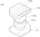
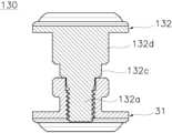
상세히, 상기 형합고정부(31)는 각 상기 착탈결합부(22,23)에 외주가 선택적으로 착탈 결합되되, 일단부에 대합악궁(3)의 구치측(3a)에 대향 밀착되도록 대합형합면부(31a)가 형성됨이 바람직하다. 이때, 상기 대합형합면부(31a)는 상기 형합고정부(31)의 일측방향을 따라 기설정된 두께를 갖도록 구비될 수 있다. 그리고, 상기 대합형합면부(31a)는 상기 대합악궁(3)의 구치측(3a)과의 대향면이 폭방향 양측으로 갈수록 상기 대합악궁(3)의 구치측(3a)을 감싸는 일측방향으로 각각 굴곡지게 연장 형성될 수 있다.In detail, the
또한, 상기 형합고정부(31)는 타단부 중앙으로부터 나사회전홈(31b)이 일측방향으로 함몰 형성됨이 바람직하다. 이때, 상기 나사회전홈(31b)의 내주에는 나사산이 형성될 수 있다.In addition, it is preferable that the
그리고, 상기 높이조절부(32)는 선택적으로 회전되며 승강되도록 상기 나사회전홈(31b)에 나사 결합되는 회전체결부(32a)가 구비됨이 바람직하다. 이때, 상기 회전체결부(32a)의 외주에 나사산이 형성될 수 있다. 여기서, 상기 회전체결부(32a)가 상기 나사회전홈(31b)에 나사 결합되며 회전됨에 따라 상기 수직고경 측정유지부(30)의 높이가 가변 조절될 수 있다.Also, the
또한, 상기 높이조절부(32)에는 상기 회전체결부(32a)의 단부에 상기 대상악궁(2)의 구치측(2a)에 대향 밀착되도록 대상형합면부(32b)가 형성됨이 바람직하다. 이때, 상기 대상형합면부(32b)는 상기 높이조절부(32)의 타측방향을 따라 기설정된 두께를 갖도록 구비될 수 있다. 그리고, 상기 대상형합면부(32b)는 상기 회전체결부(32a)의 단부에 형성되되 상기 나사회전홈(31b)의 외측으로 노출되도록 배치됨이 바람직하다. 더불어, 상기 대상형합면부(32b)는 상기 대상악궁(2)의 구치측(2a)과의 대향면이 폭방향 양측으로 갈수록 상기 대상악궁(2)의 구치측(2a)을 감싸는 타측방향으로 각각 굴곡지게 연장 형성될 수 있다.In addition, it is preferable that the
여기서, 사용자에 의해 상기 대합형합면부(31a) 및 상기 대상형합면부(32b) 간의 간격이 환자의 수직고경(VD)에 대응되도록 상기 높이조절부(32)가 상기 형합고정부(31)로부터 회전될 수 있다. 이때, 상기 대합형합면부(31a) 및 상기 대상형합면부(32b) 간의 간격이라 함은 상기 대합형합면부(31a)의 폭방향 중앙 및 상기 대상형합면부(32b)의 폭방향 중앙 사이의 간격으로 이해함이 바람직하다.Here, the
그리고, 상기 회전체결부(32a)가 상기 나사회전홈(31b)에 나사 체결되어 정방향 및 역방향으로 회전됨에 따라 상기 대합형합면부(31a) 및 상기 대상형합면부(32b) 간의 간격이 가변 조절될 수 있다.In addition, as the
한편, 상기 형합고정부(31)의 외주에는 원주방향을 따라 반경방향 내측으로 함몰외주부(31c)가 함몰 형성됨이 바람직하다. 여기서, 상기 형합고정부(31)의 타단부에는 원주방향을 따라 반경방향 외측으로 돌출되는 걸림단턱(31d)이 형성되고, 상기 함몰외주부(31c)는 상기 대합형합면부(31a) 및 상기 걸림단턱(31d) 사이에 형성됨이 바람직하다. 더욱이, 상기 대상형합면부(32b)는 상기 높이조절부(32)의 회전시 상기 걸림단턱(31d)의 단부측에 선택적으로 접촉될 수 있다.On the other hand, it is preferable that a recessed outer
그리고, 상기 착탈결합부(22,23)는 각 상기 홀더부(20,21)의 전단부 양측으로부터 상기 함몰외주부(31c)의 외경에 대응되는 간격을 두고 상호간 이격되며 각각 일체로 전향 돌출됨이 바람직하다.In addition, the
또한, 상기 착탈결합부(22,23)는 전단부(22b,23b)가 상기 함몰외주부(31c)를 감싸며 선택적으로 탄발 착탈 결합됨이 바람직하다. 이때, 상기 착탈결합부(22,23)의 각 전단부(22b,23b)는 상호 대향되는 방향으로 미세하게 굴곡진 형태로 연장 형성되되 상호간 대향 이격 배치될 수 있다. 이에 따라, 상기 착탈결합부(22,23)의 전단부(22b,23b)가 상기 함몰외주부(31c)를 감싸며 선택적으로 탄발 결합될 수 있다. 즉, 상기 착탈결합부(22,23)는 전방이 개구된 'C'자 형태로 형성됨으로 이해함이 바람직하다.In addition, it is preferable that the front ends 22b and 23b of the
더불어, 상기 착탈결합부(22,23)에는 상기 함몰외주부(31c)가 선택적으로 형합되도록 착탈홈부(24,25)가 전단 중앙으로부터 후향 함몰 형성됨이 바람직하다. 이때, 상기 착탈홈부(24,25)는 상기 함몰외주부(31c)의 외면 윤곽에 대응되는 윤곽으로 라운드지게 함몰 형성됨이 바람직하다.In addition, it is preferable that the detachable and
여기서, 상기 착탈결합부(22,23)의 각 전단부(22b,23b)는 상기 수직고경 측정유지부(30)가 상기 착탈홈부(24,25)로 삽입시, 상기 함몰외주부(31c)의 외주에 의해 가압됨에 따라 일시적으로 탄발 변형될 수 있다. 이어서, 상기 함몰외주부(31c)가 상기 착탈홈부(24,25)에 형합되면, 상기 착탈결합부(22,23)의 각 전단부(22b,23b)는 탄발 복원되어 상기 함몰외주부(31c)의 외주 일측을 감싸는 형태로 밀착될 수 있다.Here, each of the front ends 22b and 23b of the detachable and
더불어, 상기 착탈결합부(22,23)의 각 전단부(22b,23b)는 상기 수직고경 측정유지부(30)가 상기 착탈홈부(24,25)로부터 분리시, 상기 함몰외주부(31c)의 외주에 의해 가압됨에 따라 일시적으로 탄발 변형될 수 있다. 이어서, 상기 함몰외주부(31c)가 상기 착탈결합부(22,23)의 각 전단부(22b,23b)의 외측으로 이탈되면, 상기 착탈결합부(22,23)의 각 전단부(22b,23b)는 초기 위치로 탄발 복원될 수 있다.In addition, each of the front ends 22b and 23b of the detachable and
한편, 상기 핸들몸체부(10)의 후단부 중앙에는 내주에 나사산이 형성된 핸들체결홈(12)이 전향 함몰 형성됨이 바람직하다. 또한, 본 발명의 일실시예에 따른 수직고경 측정 및 유지 장치(100)는 상기 핸들체결홈(12)에 선택적으로 착탈 결합되는 핸들그립부(40)를 더 포함할 수 있다.On the other hand, it is preferable that the
여기서, 상기 핸들그립부(40)는 원통형의 핸들몸체와, 상기 핸들몸체의 단부로부터 돌출되는 핸들체결부(41)를 포함할 수 있다. 이때, 상기 핸들체결부(41)는 외주에 나사산이 형성되되 상기 핸들체결홈(12)의 내주에 대응되는 외경을 갖도록 구비됨이 바람직하다. 또한, 상기 핸들체결부(41)의 길이는 후술되는 수평정렬바(50) 및 수직정렬바(60)의 두께의 합을 초과하도록 설정될 수 있다.Here, the
그리고, 상기 수직고경 측정 및 유지 장치(100)는 수평방향, 즉 상기 핸들몸체부(10)의 폭방향으로 연장되는 수평정렬바(50)를 포함함이 바람직하다. 여기서, 상기 수평정렬바(50)는 길이방향 중앙부에 상기 핸들체결홈(12)에 정렬되며 상기 핸들체결부(41)가 관통 체결되도록 제1관통홀(50a)이 관통 형성될 수 있다. 이때, 상기 제1관통홀(50a)의 내경은 상기 핸들체결부(41)의 외경에 대응되어 설정될 수 있다.Further, the vertical diameter measuring and maintaining
더불어, 상기 수직고경 측정 및 유지 장치(100)는 상기 수평정렬바(50)와 직각으로 배치되어 상기 핸들몸체부(10)의 상하방향을 따라 연장되는 수직정렬바(60)를 더 포함함이 바람직하다. 여기서, 상기 수평정렬바(50)와 상기 수직정렬바(60)는 각 길이방향 중앙부가 상호간 직교될 수 있다.In addition, the vertical height measuring and maintaining
이때, 상기 수직정렬바(60)의 길이방향 중앙부에는 상기 핸들체결홈(12) 및 상기 제1관통홀(50a)에 정렬되며 상기 핸들체결부(41)가 관통 삽입되도록 제2관통홀(60a)이 관통 형성될 수 있다. 이때, 상기 제2관통홀(60a)의 내경은 상기 핸들체결부(41)의 외경에 대응되어 설정될 수 있다.At this time, the center portion of the
여기서, 상기 수평정렬바(50) 및 상기 수직정렬바(60)는 상기 핸들몸체부(10) 및 상기 핸들그립부(40) 사이에 전후방향을 따라 선택적으로 배치됨이 바람직하다. 예컨대, 본 발명의 일실시예에서, 상기 수평정렬바(50)의 길이방향 중앙부 전면이 상기 핸들몸체부(10)의 후면에 대향 배치될 수 있다. 또한, 상기 수평정렬바(50)의 길이방향 중앙부 후면이 상기 수직정렬바(60)의 길이방향 중앙부 전면에 대향 배치될 수 있다. 더불어, 상기 수직정렬바(60)의 길이방향 중앙부 후면이 상기 핸들그립부(40)의 전면에 대향 배치될 수 있다.Here, it is preferable that the
그리고, 상기 핸들그립부(40)가 사용자에 의해 회전됨에 따라 상기 핸들체결부(41)가 상기 제1관통홀(50a) 및 상기 제2관통홀(60a)을 관통하여 상기 핸들체결홈(12)에 체결될 수 있다. 이에 따라, 상기 수평정렬바(50) 및 상기 수직정렬바(60)가 상기 핸들몸체부(10) 및 상기 핸들그립부(40) 사이에서 가압되며 고정될 수 있다.And, as the
또한, 상기 핸들체결부(41)가 상기 핸들체결홈(12)으로부터 분리됨에 따라 상기 핸들몸체부(10)로부터 상기 핸들그립부(40), 상기 수평정렬바(50) 및 상기 수직정렬바(60)가 분리될 수 있다.In addition, as the
이때, 도면에 도시되지 않았으나, 상기 수평정렬바(50) 및 상기 수직정렬바(60) 중 어느 하나에는 상호 교차되는 길이방향 중앙부에 다른 하나의 폭에 대응되는 폭을 갖는 단턱부(미도시)가 단차지게 형성될 수도 있다. 이때, 상기 수평정렬바(50) 및 상기 수직정렬바(60) 중 다른 하나의 길이방향 중앙부는 상기 단턱부(미도시)에 걸림 결합될 수 있다. 이에 따라, 상기 수평정렬바(50) 및 상기 수직정렬바(60)가 상호간 직각으로 배치된 상태가 안정적으로 유지되어 상기 수직고경 측정지지부(30)가 상기 대상악궁(2) 및 상기 대합악궁(3)에 상기 정중선(k)을 기준으로 대칭으로 정렬될 수 있다.At this time, although not shown in the drawing, one of the
한편, 도 7은 본 발명의 일실시예에 따른 수직고경 측정 및 유지 장치에서 수직고경 측정유지부의 변형예를 나타낸 사시도이고, 도 8은 본 발명의 일실시예에 따른 수직고경 측정 및 유지 장치에서 수직고경 측정유지부의 변형예를 나타낸 단면도이다. 본 변형예에서 높이조절부(132)를 제외한 나머지 구성은 상술한 일실시예와 동일하므로 구체적인 설명은 생략하며, 동일한 구성에 대하여 동일한 도면번호로 도시한다.On the other hand, Figure 7 is a perspective view showing a modified example of the vertical height measuring and maintaining unit in the vertical dimension measuring and maintaining device according to an embodiment of the present invention, Figure 8 is a vertical dimension measuring and maintaining device according to an embodiment of the present invention It is a cross-sectional view showing a modified example of the vertical diameter measurement holding unit. In this modified example, since the rest of the components except for the
도 7 내지 도 8에서 보는 바와 같이, 수직고경 측정유지부(30)는 형합고정부(31) 및 높이조절부(132)를 포함함이 바람직하다. 이때, 상기 형합고정부(31)의 구성은 상술한 일실시예와 동일하므로 구체적인 설명은 생략한다.As shown in FIGS. 7 to 8 , the vertical diameter
또한, 상기 높이조절부(132)에서 회전체결부(132a) 및 대상형합면부(132b)의 구성은 상술한 일실시예의 회전체결부(도 6의 32a) 및 대상형합면부(도 6의 32b)와 동일하므로 구체적인 설명은 생략한다.In addition, in the
한편, 상기 높이조절부(132)에는 상기 회전체결부(132a) 및 상기 대상형합면부(132b) 사이에 보조함몰외주부(132c) 및 보조걸림단턱(132d)가 일측에서 타측방향을 따라 순차적으로 형성될 수 있다.On the other hand, in the
여기서, 상기 보조함몰외주부(132c)는 상기 높이조절부(132)의 외주에 원주방향을 따라 반경방향 내측으로 함몰 형성됨이 바람직하다. 이때, 상기 보조함몰외주부(132c)의 외경은 일실시예의 함몰외주부(도 5의 31c)의 외경에 대응되어 설정될 수 있다. 더불어, 상기 보조걸림단턱(132d)은 상기 높이조절부(132)의 원주방향을 따라 반경방향 외측으로 돌출 형성됨이 바람직하다.Here, it is preferable that the auxiliary recessed outer
이에 따라, 일실시예에서 상술한 착탈결합부(도 2의 22,23)가 상기 함몰외주부(도 5의 31c) 및 상기 보조함몰외주부(132c) 중 하나에 선택적으로 착탈 결합될 수 있어 사용편의성이 개선될 수 있다.Accordingly, in one embodiment, the above-described detachable coupling parts (22 and 23 in FIG. 2) can be selectively detachably coupled to one of the recessed outer circumferential portion (31c in FIG. this can be improved.
한편, 도 9 및 도 10 및 도 11은 본 발명의 일실시예에 따른 수직고경 측정 및 유지 장치에서 수직고경 측정유지부의 사용상태를 나타낸 사용예시도이다.Meanwhile, FIGS. 9, 10, and 11 are diagrams illustrating use of the vertical diameter measuring and maintaining unit in the vertical diameter measuring and maintaining device according to an embodiment of the present invention.
도 9 내지 도 11을 참조하여, 이하에서 본 발명에 따른 수직고경 측정 및 유지 방법을 설명한다.Referring to FIGS. 9 to 11 , a method for measuring and maintaining a vertical diameter according to the present invention will be described below.
먼저, 상기 핸들몸체부(10)에 상기 핸들그립부(40), 상기 수평정렬바(50) 및 상기 수직정렬바(60)가 결합되어 준비된다. 더불어, 상기 핸들몸체부(10)에 연결된 각 상기 홀더부(20,21)의 전단부측 상기 착탈결합부(도 2의 22,23)에 상기 수직고경 측정유지부(30)가 결합되어 준비된다.First, the
그리고, 상기 수직고경 측정 및 유지 장치(100)가 환자의 구강에 삽입된다. 이때, 각 상기 수직고경 측정유지부(30)가 상기 대상악궁(2)의 구치측(2a) 및 상기 대상악궁(3)의 구치측(3a) 사이에 각각 배치된다.Then, the vertical dimension measuring and maintaining
이를 위해, 각 상기 수직고경 측정유지부(30) 간의 간격(w1)은 상기 대상악궁(2)의 각 구치측 간의 간격(w2)에 대응되도록 정렬될 수 있다. 또는, 각 상기 수직고경 측정유지부(30) 간의 간격(w1)은 상기 대합악궁(3)의 각 구치측 간의 간격(w2)에 대응되도록 정렬될 수 있다. 즉, 각 상기 수직고경 측정유지부(30) 간의 간격(w1)은 상기 대상악궁(2) 및 상기 대합악궁(3)의 치열궁 중 각 구치측 간의 간격에 대응되도록 정렬될 수 있다.To this end, the distance w1 between the vertical diameter measurement and holding
이때, 상기 대상악궁(2)의 각 구치측 간의 간격(w2) 및 상기 대합악궁(3)의 각 구치측 간의 간격(w2)이 상호간 실질적으로 동일한 것으로 이해함이 바람직하다.At this time, it is preferable to understand that the interval w2 between each posterior tooth side of the
즉, 각 상기 홀더부(20,21)의 전단부 간의 간격(w1)이 악궁의 좌측 및 우측 구치측 간의 간격(w2)에 대응되도록 각 상기 홀더부(20,21)의 전단부가 상기 힌지연결부(11)를 중심으로 수평 회전되어 정렬된다. 이때, 각 상기 홀더부(20,21)의 전단부 간의 간격(w1)이 설정된 후, 상기 힌지연결부(11)의 회전을 통해 각 상기 홀더부(20,21)의 후방부가 상기 핸들몸체부(10) 및 힌지연결부(11) 사이에 가고정될 수 있다.That is, the front ends of each of the
그리고, 상기 수직고경 측정 및 유지 장치(100)가 환자의 구강에 삽입시, 상기 수평정렬바(50) 및 상기 수직정렬바(60)가 상기 정중선(k) 및 교합평면에 각각 정렬되도록 배치될 수 있다. 이때, 상기 교합평면이라 함은 상기 정중선(k)과 직교되되 상기 대합악궁(3)의 단부를 따라 수평으로 연장되는 가상의 평면으로 이해함이 바람직하다. 더불어, 상기 핸들그립부(40)의 중앙부가 상기 정중선(k) 및 상기 교합평면이 직교되는 위치로 정렬될 수 있다.In addition, when the vertical dimension measuring and maintaining
이어서, 상기 대합형합면부(31a)가 상기 대합악궁(3)의 구치측(3a)에 형합 고정된다. 이때, 경우에 따라 상기 대합형합면부(31a) 및 상기 대합악궁(3)의 구치측(3a) 사이에 경화성 수지가 도포되어 상기 대합형합면부(31a) 및 상기 대합악궁(3)의 구치측(3a)이 상호간 접합되며 고정될 수도 있다.Subsequently, the opposing
그리고, 상기 높이조절부(32)가 상기 형합고정부(31)로부터 사용자에 의해 회전됨에 따라 상기 대합형합면부(31a) 및 상기 대상형합면부(32b) 간의 간격이 환자의 수직고경(VD)에 대응되도록 설정된다. 이때, 상기 높이조절부(32)는 환자의 구강 내에서 사용자에 의해 회전될 수 있으며, 상기 높이조절부(32)가 구강 외부에서 회전된 후 사용자에 의해 구강 내로 삽입될 수도 있다.In addition, as the
여기서, 상기 대합형합면부(31a) 및 상기 대상형합면부(32b) 간의 간격이 환자의 수직고경(VD)에 대응되도록 설정된 후, 상기 대상형합면부(32b)는 상기 대상악궁(2)의 구치측(2a)에 형합 고정될 수 있다.Here, after the interval between the
그리고, 상기 수직고경 측정유지부(30)가 상기 대상악궁(2)의 구치측(2a) 및 상기 대합악궁(3)의 구치측(3a) 사이에 고정된 상태에서, 사용자의 견인력에 의해 상기 핸들몸체부(10) 및 상기 핸들그립부(40)가 구강의 외측방향으로 당겨질 수 있다. 이에 따라, 상기 착탈결합부(22,23)가 각 상기 수직고경 측정유지부(30)로부터 탄발 변형되며 분리되어 상기 홀더부(20)가 구강으로부터 구강 외측으로 제거될 수 있다.In addition, in a state in which the vertical height measurement and holding
또한, 상기 수직고경 측정유지부(30)가 상기 대상악궁(2)의 구치측(2a) 및 상기 대합악궁(3)의 구치측(3a) 사이에 고정된 상태에서, 상기 수직고경(VD), 상기 대상악궁(2) 및 상기 대합악궁(3)에 대한 3차원 이미지데이터가 3차원 스캐닝장치(s)에 의해 획득된다. 이에 따라, 상기 수직고경 측정유지부(30)에 의해 정확한 상기 수직고경(VD)이 유지되는 상태에서 무치악 환자의 대상악궁(2) 시술을 위한 상기 3차원 이미지데이터가 정밀하게 획득되므로 제조되는 보철물의 제조정밀성이 개선될 수 있다.In addition, in a state in which the vertical dimension
이처럼, 본 발명은As such, the present invention
첫째, 한쌍의 상기 홀더부(20,21) 전단부에 형성된 상기 착탈결합부(22,23)에 착탈된 높이 조절이 가능한 각 상기 수직고경 측정유지부(30)가 치열궁의 구치측 너비에 대응되는 간격을 두고 벌어지며 이격될 수 있다. 이를 통해, 상기 홀더부(20,21)가 회전 조절된 후 가고정되므로 수직고경 측정의 호환성 및 작업편의성이 현저히 개선될 수 있다.First, each of the height-adjustable vertical height
즉, 상기 홀더부(20,21)의 전단부에 형성된 상기 착탈결합부(22,23)에 착탈된 상기 수직고경 측정유지부(30)가 상기 대상악궁(2) 및 상기 대합악궁(3)의 각 구치측(2a,3a) 사이에 용이하게 배치될 수 있다.That is, the vertical height measurement and holding
이때, 상기 홀더부(20,21)의 전단부가 상기 힌지연결부(11)를 중심으로 수평 회전되어 상기 대상악궁(2)의 구치측 치열궁 너비에 대응되는 간격을 두고 이격되며 가고정된 상태에서 구강에 삽입되므로 작업편의성이 현저히 개선될 수 있다.At this time, the front ends of the
또한, 상기 수직고경 측정유지부(30)가 상기 대상악궁(2) 및 상기 대합악궁(3)의 각 구치측(2a,3a) 사이에 고정되며 수직고경(VD)이 획득 및 유지된 상태에서, 상기 착탈결합부(22,23)가 상기 수직고경 측정유지부(30)로부터 탄발 변형되며 분리되어 상기 홀더부(20,21) 및 상기 핸들몸체부(10)를 간편하게 탄발 착탈할 수 있다. 이에 따라, 상기 3차원 스캐닝장치(s)를 통한 3차원 이미지 스캐닝시 상기 수직고경 측정유지부(30)가 구강 외측으로 용이하게 노출되므로 수직고경 측정용이성이 개선될 수 있다. 이와 동시에, 정밀한 3차원 이미지데이터가 수집되어 제조되는 보철물의 제조정밀성이 개선될 수 있다.In addition, in a state in which the vertical dimension measurement and holding
또한, 분리된 상기 홀더부(20,21) 및 상기 핸들몸체부(10)는 세척 및 소독 후 재사용 가능하므로 친환경성이 현저히 개선되며, 다양한 크기의 치열궁을 갖는 환자의 구강에 호환 사용될 수 있어 호환성이 개선될 수 있다.In addition, since the separated
그리고, 상기 착탈결합부(22,23)는 상기 형합고정부(31) 외주에 함몰된 상기 함몰외주부(31c)를 감싸도록 전향 돌출 형성되되 상기 착탈결합부(22,23)의 전단 중앙으로부터 상기 함몰외주부(31c)의 외면 윤곽에 대응되는 윤곽으로 라운드진 착탈홈부(24,25)가 전단 중앙으로부터 후향 함몰 형성된다. 이에 따라, 상기 함몰외주부(31c)가 상기 착탈홈부(24,25)에 선택적으로 형합되어 상기 수직고경 측정유지부(30)의 구강 배치시 견고한 지지력을 제공하므로 상기 수직고경 측정유지부(30)가 상기 착탈결합부(22,23)로부터 이탈이 방지될 수 있다.In addition, the
더욱이, 각 상기 홀더부(20,21)의 후방부는 상기 힌지연결부(11) 및 상기 핸들몸체부(10) 사이에 배치될 수 있다. 이때, 상기 힌지연결부(11)는 각 상기 홀더부(20,21)를 회전 가압하여 각 상기 홀더부(20,21)가 가고정되도록 각 상기 홀더부(20,21)의 후방부 및 상기 핸들몸체부(10)에 힌지 연결된다. 그리고, 각 상기 홀더부(20,21)의 전단부가 상기 힌지연결부(11)를 중심으로 수평 회전될 수 있다. 이를 통해, 각 상기 수직고경 측정유지부(30) 간의 간격(w1)이 상기 대상악궁(2)의 각 구치측 간의 간격(w2)에 대응되도록 정렬된 후 가고정될 수 있어 사용편의성이 개선될 수 있다.Furthermore, the rear portion of each of the
또한, 상호 직교되며 수평방향 및 상하방향으로 각각 연장되는 상기 수평정렬바(50) 및 상기 수직정렬바(60)가 상기 핸들몸체부(10) 및 상기 핸들그립부(40) 사이에 선택적으로 착탈 결합된다. 이에 따라, 상기 정중선(k) 및 상기 교합평면이 정확하게 정렬된 상태에서 상기 수직고경 측정유지부(30)가 상기 대상악궁(2) 및 상기 대합악궁(3)의 각 구치측(2a,3a) 사이에 정밀하게 정렬되어 고정될 수 있다. 이를 통해, 최종 제조된 보철물의 제조정밀성이 현저히 개선될 수 있다.In addition, the
더욱이, 각 상기 홀더부(20,21)는 길이방향 중앙부 일측(20c,21c)이 절곡지게 형성되되, 각 상기 홀더부(20,21)의 전단부는 각 상기 홀더부(20,21)의 후단부보다 상기 핸들몸체부(10)의 폭방향 양측으로 배치된다. 이에 따라, 상기 홀더부(20,21)를 구강에 삽입하기만 하면 상기 수직고경 측정유지부(30)가 상기 대상악궁(2)의 구치측(2a) 및 상기 대합악궁(3)의 구치측(3a) 사이로 용이하게 이동되므로 사용편의성이 개선될 수 있다.Moreover, each of the
또한, 상기 대합형합면부(31a) 및 상기 대상형합면부(32b)는 폭방향 양측으로 갈수록 상기 대합악궁(3)의 구치측(3a) 및 상기 대상악궁(2)의 구치측(2a)을 감싸는 일측방향 및 타측방향으로 각각 굴곡지게 연장 형성된다. 이를 통해, 상기 수직고경 측정유지부(30)에 의해 수직고경(VD)이 획득된 상태에서 흔들림 등에 의한 오차 발생이 최소화되며 유지되므로 최종 보철물의 제조정밀성이 개선될 수 있다.In addition, the opposing
이때, 이상에서 기재된 "포함하다", "구성하다" 또는 "구비하다" 등의 용어는, 특별히 반대되는 기재가 없는 한, 해당 구성 요소가 내재할 수 있음을 의미하는 것이므로, 다른 구성 요소를 제외하는 것이 아니라 다른 구성 요소를 더 포함할 수 있는 것으로 해석되어야 한다. 기술적이거나 과학적인 용어를 포함한 모든 용어들은, 다르게 정의되지 않는 한, 본 발명이 속하는 기술 분야에서 통상의 지식을 가진 자에 의해 일반적으로 이해되는 것과 동일한 의미가 있다. 사전에 정의된 용어와 같이 일반적으로 사용되는 용어들은 관련 기술의 문맥상의 의미와 일치하는 것으로 해석되어야 하며, 본 발명에서 명백하게 정의하지 않는 한, 이상적이거나 과도하게 형식적인 의미로 해석되지 않는다.In this case, terms such as "include", "comprise" or "have" described above mean that the corresponding component may be present unless otherwise stated, excluding other components. It should be construed as being able to further include other components. All terms, including technical or scientific terms, have the same meaning as commonly understood by a person of ordinary skill in the art to which the present invention belongs, unless defined otherwise. Commonly used terms, such as terms defined in a dictionary, should be interpreted as being consistent with the contextual meaning of the related art, and unless explicitly defined in the present invention, they are not interpreted in an ideal or excessively formal meaning.
이상 설명한 바와 같이, 본 발명은 상술한 각 실시예에 한정되는 것은 아니며, 본 발명의 청구항에서 청구하는 범위를 벗어남 없이 본 발명이 속하는 기술분야에서 통상의 지식을 가진 자에 의해 변형 실시되는 것은 가능하며, 이러한 변형 실시는 본 발명의 범위에 속한다.As described above, the present invention is not limited to the above-described embodiments, and it is possible to modify and implement the present invention by those skilled in the art without departing from the scope claimed in the claims of the present invention. And, such modifications fall within the scope of the present invention.
10: 핸들몸체부20,21: 홀더부
30,130: 수직고경 측정지지부40: 핸들그립부
50: 수평정렬바60: 수직정렬바
100: 수직고경 측정 및 유지 장치10: handle
30,130: vertical height measurement support 40: handle grip
50: horizontal alignment bar 60: vertical alignment bar
100: Vertical height measuring and maintaining device
Claims (6)
Translated fromKorean한쌍으로 구비되어 각 상기 힌지연결부에 각 후방부가 힌지 연결되며, 전단부가 대상악궁의 너비에 대응되는 간격을 두고 상기 힌지연결부를 중심으로 수평 회전되어 상호 이격되도록 각 상기 후방부로부터 각각 일체로 전향 연장되고, 각 상기 전단부에 착탈결합부가 일체로 돌출 형성되는 홀더부; 및
각 상기 착탈결합부에 외주가 선택적으로 착탈 결합되되 일단부에 대합악궁의 구치측에 대향 밀착되도록 대합형합면부가 형성되며 타단부 중앙으로부터 나사회전홈이 일측방향으로 함몰 형성되는 형합고정부와, 선택적으로 회전되며 승강되도록 상기 나사회전홈에 나사 결합되는 회전체결부가 구비되며 상기 회전체결부의 단부에 상기 대상악궁의 구치측에 대향 밀착되도록 대상형합면부가 형성되는 높이조절부를 포함하는 수직고경 측정유지부를 포함하는 수직고경 측정 및 유지 장치.A handle body portion provided with a pair of hinge connections arranged symmetrically with respect to the central portion on both sides;
Provided as a pair, each rear part is hingedly connected to each of the hinge connection parts, and the front ends are horizontally rotated around the hinge connection part at intervals corresponding to the width of the target arch, so that they are spaced apart from each other. And, the holder portion in which the detachable coupling portion is integrally formed to protrude from each of the front ends; and
The outer periphery of each detachable coupling part is selectively detachably coupled, but at one end, an opposing mating surface is formed so as to be in close contact with the molar side of the opposing arch, and a screw rotation groove is formed in one direction from the center of the other end. A vertical diameter measurement comprising a height adjusting unit having a rotational fastening portion screwed into the screw rotation groove to be selectively rotated and moved up and down, and a counter-joint portion formed at an end of the rotation fastening portion so as to be in close contact with the molar side of the target arch. A device for measuring and maintaining a vertical diameter including a holding part.
상기 형합고정부의 외주에는 원주방향을 따라 반경방향 내측으로 함몰외주부가 함몰 형성되며,
상기 착탈결합부는 각 상기 홀더부의 전단부 양측으로부터 전향 돌출되되, 각 상기 착탈결합부의 전단부가 상호 대향되는 방향으로 굴곡지게 연장되며 상호간 대향 이격 배치되며 상기 함몰외주부를 감싸며 선택적으로 탄발 결합되고,
상기 착탈결합부에는 상기 함몰외주부의 외면 윤곽에 대응되는 윤곽으로 라운드진 착탈홈부가 전단 중앙으로부터 후향 함몰 형성됨을 특징으로 하는 수직고경 측정 및 유지 장치.According to claim 1,
The outer circumference of the mold fixing part is formed with a recessed outer circumference in a radially inward direction along the circumferential direction,
The detachable coupling portion protrudes forward from both sides of the front end of each holder portion, and the front ends of each detachable coupling portion are curvedly extended in mutually opposing directions, spaced apart from each other, and wrapped around the recessed outer circumference, optionally elastically coupled,
Vertical dimension measuring and maintaining device, characterized in that in the detachable coupling portion, a detachable groove portion rounded in an outline corresponding to the outer contour of the outer circumference of the depression is recessed backward from the center of the front end.
상기 형합고정부의 타단부에는 원주방향을 따라 반경방향 외측으로 돌출되는 걸림단턱이 형성되고,
상기 함몰외주부는 상기 대합형합면부 및 상기 걸림단턱 사이에 형성됨을 특징으로 하는 수직고경 측정 및 유지 장치.According to claim 2,
A hooking step protruding outward in a radial direction along the circumferential direction is formed at the other end of the mold fixing part,
The vertical diameter measuring and maintaining device, characterized in that the recessed outer circumferential portion is formed between the mating surface portion and the engaging step.
각 상기 홀더부의 후방부는 상기 힌지연결부 및 상기 핸들몸체부 사이에 배치되되,
상기 힌지연결부는 각 상기 홀더부를 회전 가압하여 각 상기 홀더부가 가고정되도록 각 상기 홀더부의 후방부 및 상기 핸들몸체부에 힌지 연결됨을 특징으로 하는 수직고경 측정 및 유지 장치.According to claim 1,
The rear part of each holder part is disposed between the hinge connection part and the handle body part,
The vertical diameter measuring and maintaining device, characterized in that the hinge connection part is hinged to the rear part of each holder part and the handle body part so that each of the holder parts is temporarily fixed by rotationally pressing each holder part.
상기 핸들몸체부의 후단부 중앙에 전향 함몰 형성되는 핸들체결홈에 선택적으로 착탈 결합되는 핸들그립부와,
상기 핸들몸체부 및 상기 핸들그립부 사이에 배치되되 상호 직교되며 수평방향 및 상하방향으로 각각 연장되는 수평정렬바 및 수직정렬바를 더 포함함을 특징으로 하는 수직고경 측정 및 유지 장치.According to claim 1,
A handle grip portion selectively detachably coupled to a handle fastening groove formed in a forward depression at the center of the rear end of the handle body portion;
Vertical diameter measurement and maintenance device characterized in that it further comprises a horizontal alignment bar and a vertical alignment bar disposed between the handle body and the handle grip portion orthogonal to each other and extending in the horizontal and vertical directions, respectively.
각 상기 홀더부는 길이방향 중앙부 일측이 절곡지게 형성되되, 각 상기 홀더부의 전단부는 각 상기 홀더부의 후단부보다 상기 핸들몸체부의 폭방향 양측으로 배치되고,
상기 대합형합면부 및 상기 대상형합면부는 폭방향 양측으로 갈수록 상기 대합악궁의 구치측 및 상기 대상악궁의 구치측을 감싸는 일측방향 및 타측방향으로 각각 굴곡지게 연장 형성됨을 특징으로 하는 수직고경 측정 및 유지 장치.According to claim 1,
Each holder part is formed such that one side of the central part in the longitudinal direction is bent, and the front end of each holder part is disposed on both sides of the handle body in the width direction rather than the rear end of each holder part,
Measuring and maintaining the vertical diameter, characterized in that the counter-shaped joint surface portion and the target-shaped joint surface portion are each curvedly extended in one direction and the other direction surrounding the molar side of the arch and the molar side of the target arch toward both sides in the width direction. Device.
Priority Applications (1)
| Application Number | Priority Date | Filing Date | Title |
|---|---|---|---|
| KR1020220014651AKR102660107B1 (en) | 2022-02-04 | 2022-02-04 | measuring and holding apparatus for occlusal vertical dimension |
Applications Claiming Priority (1)
| Application Number | Priority Date | Filing Date | Title |
|---|---|---|---|
| KR1020220014651AKR102660107B1 (en) | 2022-02-04 | 2022-02-04 | measuring and holding apparatus for occlusal vertical dimension |
Publications (2)
| Publication Number | Publication Date |
|---|---|
| KR20230118282Atrue KR20230118282A (en) | 2023-08-11 |
| KR102660107B1 KR102660107B1 (en) | 2024-04-23 |
Family
ID=87566151
Family Applications (1)
| Application Number | Title | Priority Date | Filing Date |
|---|---|---|---|
| KR1020220014651AActiveKR102660107B1 (en) | 2022-02-04 | 2022-02-04 | measuring and holding apparatus for occlusal vertical dimension |
Country Status (1)
| Country | Link |
|---|---|
| KR (1) | KR102660107B1 (en) |
Citations (6)
| Publication number | Priority date | Publication date | Assignee | Title |
|---|---|---|---|---|
| US6582931B1 (en)* | 2000-11-08 | 2003-06-24 | Panadent Corporation | Dento-facial analyzer |
| US20040166467A1 (en)* | 2003-02-25 | 2004-08-26 | Crow Nathaniel David | Dental marking film holder |
| US20060121409A1 (en)* | 2004-10-29 | 2006-06-08 | Juan Olivier | Methods and apparatus for determining horizontal and vertical plane orientation for construction of dental prostheses |
| KR101365907B1 (en) | 2012-11-13 | 2014-03-12 | 정용재 | The vertical demension control device |
| KR20160010227A (en)* | 2014-07-18 | 2016-01-27 | 이채붕 | The articulator and the articulating Method of the same |
| KR102193852B1 (en)* | 2019-08-14 | 2020-12-22 | 주식회사 디오 | occlusal vertical dimension measuring device |
- 2022
- 2022-02-04KRKR1020220014651Apatent/KR102660107B1/enactiveActive
Patent Citations (6)
| Publication number | Priority date | Publication date | Assignee | Title |
|---|---|---|---|---|
| US6582931B1 (en)* | 2000-11-08 | 2003-06-24 | Panadent Corporation | Dento-facial analyzer |
| US20040166467A1 (en)* | 2003-02-25 | 2004-08-26 | Crow Nathaniel David | Dental marking film holder |
| US20060121409A1 (en)* | 2004-10-29 | 2006-06-08 | Juan Olivier | Methods and apparatus for determining horizontal and vertical plane orientation for construction of dental prostheses |
| KR101365907B1 (en) | 2012-11-13 | 2014-03-12 | 정용재 | The vertical demension control device |
| KR20160010227A (en)* | 2014-07-18 | 2016-01-27 | 이채붕 | The articulator and the articulating Method of the same |
| KR102193852B1 (en)* | 2019-08-14 | 2020-12-22 | 주식회사 디오 | occlusal vertical dimension measuring device |
Also Published As
| Publication number | Publication date |
|---|---|
| KR102660107B1 (en) | 2024-04-23 |
Similar Documents
| Publication | Publication Date | Title |
|---|---|---|
| US8277216B2 (en) | Method and apparatus for preparing denture | |
| KR102070682B1 (en) | Edentulous Tray and Recording conversion Method | |
| CA2728309A1 (en) | Dentures, dental arches and methods of manufacture | |
| US20090117514A1 (en) | Method and components for producing edentulous dentures | |
| JP2013521096A (en) | Articulator | |
| CA3063024A1 (en) | Standard denture alignment jig, denture preparation kit, and method for preparing denture using the jig and the kit | |
| CN111743648A (en) | Median jaw tray, method of use and method of making digital complete denture | |
| KR20170082605A (en) | Bite registration tool, bite registration tool set, and suitable bite registration method | |
| US9737384B2 (en) | Dynamically generated dental articulator controls | |
| WO2004082511A1 (en) | Dental face bow | |
| CN118078472A (en) | A central jaw denture, denture restoration system and use method for determining jaw plane and jaw position relationship | |
| KR20230118282A (en) | measuring and holding apparatus for occlusal vertical dimension | |
| Ari et al. | Management of a complete denture in the flat mandibular ridge using a semi-adjustable articulator along with an effective suction method | |
| KR102193807B1 (en) | Recording conversion system and method including mandibular movement sensor | |
| KR20190080585A (en) | Acquisition method of dental interocclusal records and byte holder connecting device to move dental interocclusal records to articulator | |
| CN114224547B (en) | Digital Gothic bow device and manufacturing method thereof | |
| KR102500317B1 (en) | universal partial bite guide for measuring occlusal vertical dimension | |
| EP3927279B1 (en) | Prosthetic tooth, method for manufacturing thereof, and use of the same | |
| US20230112706A1 (en) | Prosthetic tooth or denture base | |
| CN111839772A (en) | Jaw position relationship recording auxiliary device and jaw position relationship recording method | |
| CN116672109A (en) | A method for constructing a personalized occlusal tray model and its preparation method | |
| Ibrahim | Metal Versus Plastic Copings Regarding the Accuracy of Implant Transfer Impression Techniques [in vitro study] | |
| KR20060000201U (en) | Impression Metal Cover Connector | |
| JP2016501058A (en) | Device for fixing the molding and method suitable therefor |
Legal Events
| Date | Code | Title | Description |
|---|---|---|---|
| PA0109 | Patent application | Patent event code:PA01091R01D Comment text:Patent Application Patent event date:20220204 | |
| PA0201 | Request for examination | ||
| PG1501 | Laying open of application | ||
| E701 | Decision to grant or registration of patent right | ||
| PE0701 | Decision of registration | Patent event code:PE07011S01D Comment text:Decision to Grant Registration Patent event date:20240119 | |
| GRNT | Written decision to grant | ||
| PR0701 | Registration of establishment | Comment text:Registration of Establishment Patent event date:20240418 Patent event code:PR07011E01D | |
| PR1002 | Payment of registration fee | Payment date:20240418 End annual number:3 Start annual number:1 | |
| PG1601 | Publication of registration |