KR20230097437A - Method for measruing inserting length using shape of insertion device and insertion device for the same - Google Patents
Method for measruing inserting length using shape of insertion device and insertion device for the sameDownload PDFInfo
- Publication number
- KR20230097437A KR20230097437AKR1020210186929AKR20210186929AKR20230097437AKR 20230097437 AKR20230097437 AKR 20230097437AKR 1020210186929 AKR1020210186929 AKR 1020210186929AKR 20210186929 AKR20210186929 AKR 20210186929AKR 20230097437 AKR20230097437 AKR 20230097437A
- Authority
- KR
- South Korea
- Prior art keywords
- sensing unit
- target
- sensing
- candidate
- insertion device
- Prior art date
- Legal status (The legal status is an assumption and is not a legal conclusion. Google has not performed a legal analysis and makes no representation as to the accuracy of the status listed.)
- Granted
Links
- 238000003780insertionMethods0.000titleclaimsabstractdescription186
- 230000037431insertionEffects0.000titleclaimsabstractdescription186
- 238000000034methodMethods0.000titleclaimsabstractdescription40
- 230000008859changeEffects0.000claimsabstractdescription60
- 210000003323beakAnatomy0.000claimsdescription31
- 238000001514detection methodMethods0.000claimsdescription11
- 238000004364calculation methodMethods0.000claimsdescription10
- 230000014509gene expressionEffects0.000claimsdescription9
- 208000012287ProlapseDiseases0.000claimsdescription7
- 238000013480data collectionMethods0.000claimsdescription5
- 230000008569processEffects0.000claimsdescription5
- 102100036419Calmodulin-like protein 5Human genes0.000claimsdescription4
- 101000714353Homo sapiens Calmodulin-like protein 5Proteins0.000claimsdescription4
- 238000005259measurementMethods0.000description10
- 238000012545processingMethods0.000description8
- 239000013307optical fiberSubstances0.000description7
- 238000000691measurement methodMethods0.000description4
- 238000012986modificationMethods0.000description3
- 230000004048modificationEffects0.000description3
- 210000004204blood vesselAnatomy0.000description2
- 210000001072colonAnatomy0.000description2
- 238000010586diagramMethods0.000description2
- 230000000694effectsEffects0.000description2
- 238000005516engineering processMethods0.000description2
- 238000011160researchMethods0.000description2
- 238000001228spectrumMethods0.000description2
- 210000004534cecumAnatomy0.000description1
- 238000005253claddingMethods0.000description1
- 238000004590computer programMethods0.000description1
- 238000010276constructionMethods0.000description1
- 238000013479data entryMethods0.000description1
- 238000013500data storageMethods0.000description1
- 238000009826distributionMethods0.000description1
- 230000006870functionEffects0.000description1
- 238000007689inspectionMethods0.000description1
- 238000004519manufacturing processMethods0.000description1
- 239000000463materialSubstances0.000description1
- 238000002324minimally invasive surgeryMethods0.000description1
- 238000012544monitoring processMethods0.000description1
- 230000006855networkingEffects0.000description1
- 230000003287optical effectEffects0.000description1
- 210000000056organAnatomy0.000description1
- 230000001151other effectEffects0.000description1
- 230000002093peripheral effectEffects0.000description1
- 230000000704physical effectEffects0.000description1
- 238000007639printingMethods0.000description1
- 238000003860storageMethods0.000description1
- 238000001356surgical procedureMethods0.000description1
- 230000033772system developmentEffects0.000description1
- 210000001835visceraAnatomy0.000description1
- XLYOFNOQVPJJNP-UHFFFAOYSA-NwaterSubstancesOXLYOFNOQVPJJNP-UHFFFAOYSA-N0.000description1
Images


Classifications
- A—HUMAN NECESSITIES
- A61—MEDICAL OR VETERINARY SCIENCE; HYGIENE
- A61B—DIAGNOSIS; SURGERY; IDENTIFICATION
- A61B34/00—Computer-aided surgery; Manipulators or robots specially adapted for use in surgery
- A61B34/20—Surgical navigation systems; Devices for tracking or guiding surgical instruments, e.g. for frameless stereotaxis
- A—HUMAN NECESSITIES
- A61—MEDICAL OR VETERINARY SCIENCE; HYGIENE
- A61B—DIAGNOSIS; SURGERY; IDENTIFICATION
- A61B34/00—Computer-aided surgery; Manipulators or robots specially adapted for use in surgery
- A61B34/10—Computer-aided planning, simulation or modelling of surgical operations
- A—HUMAN NECESSITIES
- A61—MEDICAL OR VETERINARY SCIENCE; HYGIENE
- A61B—DIAGNOSIS; SURGERY; IDENTIFICATION
- A61B90/00—Instruments, implements or accessories specially adapted for surgery or diagnosis and not covered by any of the groups A61B1/00 - A61B50/00, e.g. for luxation treatment or for protecting wound edges
- A61B90/06—Measuring instruments not otherwise provided for
- A—HUMAN NECESSITIES
- A61—MEDICAL OR VETERINARY SCIENCE; HYGIENE
- A61M—DEVICES FOR INTRODUCING MEDIA INTO, OR ONTO, THE BODY; DEVICES FOR TRANSDUCING BODY MEDIA OR FOR TAKING MEDIA FROM THE BODY; DEVICES FOR PRODUCING OR ENDING SLEEP OR STUPOR
- A61M25/00—Catheters; Hollow probes
- A61M25/01—Introducing, guiding, advancing, emplacing or holding catheters
- A61M25/0105—Steering means as part of the catheter or advancing means; Markers for positioning
- A—HUMAN NECESSITIES
- A61—MEDICAL OR VETERINARY SCIENCE; HYGIENE
- A61B—DIAGNOSIS; SURGERY; IDENTIFICATION
- A61B34/00—Computer-aided surgery; Manipulators or robots specially adapted for use in surgery
- A61B34/10—Computer-aided planning, simulation or modelling of surgical operations
- A61B2034/101—Computer-aided simulation of surgical operations
- A61B2034/105—Modelling of the patient, e.g. for ligaments or bones
- A—HUMAN NECESSITIES
- A61—MEDICAL OR VETERINARY SCIENCE; HYGIENE
- A61B—DIAGNOSIS; SURGERY; IDENTIFICATION
- A61B34/00—Computer-aided surgery; Manipulators or robots specially adapted for use in surgery
- A61B34/10—Computer-aided planning, simulation or modelling of surgical operations
- A61B2034/107—Visualisation of planned trajectories or target regions
- A—HUMAN NECESSITIES
- A61—MEDICAL OR VETERINARY SCIENCE; HYGIENE
- A61B—DIAGNOSIS; SURGERY; IDENTIFICATION
- A61B34/00—Computer-aided surgery; Manipulators or robots specially adapted for use in surgery
- A61B34/20—Surgical navigation systems; Devices for tracking or guiding surgical instruments, e.g. for frameless stereotaxis
- A61B2034/2046—Tracking techniques
- A61B2034/2061—Tracking techniques using shape-sensors, e.g. fiber shape sensors with Bragg gratings
- A—HUMAN NECESSITIES
- A61—MEDICAL OR VETERINARY SCIENCE; HYGIENE
- A61B—DIAGNOSIS; SURGERY; IDENTIFICATION
- A61B90/00—Instruments, implements or accessories specially adapted for surgery or diagnosis and not covered by any of the groups A61B1/00 - A61B50/00, e.g. for luxation treatment or for protecting wound edges
- A61B90/06—Measuring instruments not otherwise provided for
- A61B2090/062—Measuring instruments not otherwise provided for penetration depth
- A—HUMAN NECESSITIES
- A61—MEDICAL OR VETERINARY SCIENCE; HYGIENE
- A61B—DIAGNOSIS; SURGERY; IDENTIFICATION
- A61B90/00—Instruments, implements or accessories specially adapted for surgery or diagnosis and not covered by any of the groups A61B1/00 - A61B50/00, e.g. for luxation treatment or for protecting wound edges
- A61B90/06—Measuring instruments not otherwise provided for
- A61B2090/064—Measuring instruments not otherwise provided for for measuring force, pressure or mechanical tension
- A—HUMAN NECESSITIES
- A61—MEDICAL OR VETERINARY SCIENCE; HYGIENE
- A61B—DIAGNOSIS; SURGERY; IDENTIFICATION
- A61B2562/00—Details of sensors; Constructional details of sensor housings or probes; Accessories for sensors
- A61B2562/02—Details of sensors specially adapted for in-vivo measurements
- A61B2562/0261—Strain gauges
- A—HUMAN NECESSITIES
- A61—MEDICAL OR VETERINARY SCIENCE; HYGIENE
- A61M—DEVICES FOR INTRODUCING MEDIA INTO, OR ONTO, THE BODY; DEVICES FOR TRANSDUCING BODY MEDIA OR FOR TAKING MEDIA FROM THE BODY; DEVICES FOR PRODUCING OR ENDING SLEEP OR STUPOR
- A61M25/00—Catheters; Hollow probes
- A61M25/01—Introducing, guiding, advancing, emplacing or holding catheters
- A61M25/0105—Steering means as part of the catheter or advancing means; Markers for positioning
- A61M2025/0166—Sensors, electrodes or the like for guiding the catheter to a target zone, e.g. image guided or magnetically guided
Landscapes
- Health & Medical Sciences (AREA)
- Life Sciences & Earth Sciences (AREA)
- Surgery (AREA)
- Engineering & Computer Science (AREA)
- Veterinary Medicine (AREA)
- Public Health (AREA)
- General Health & Medical Sciences (AREA)
- Biomedical Technology (AREA)
- Heart & Thoracic Surgery (AREA)
- Animal Behavior & Ethology (AREA)
- Molecular Biology (AREA)
- Medical Informatics (AREA)
- Nuclear Medicine, Radiotherapy & Molecular Imaging (AREA)
- Robotics (AREA)
- Pathology (AREA)
- Oral & Maxillofacial Surgery (AREA)
- Biophysics (AREA)
- Pulmonology (AREA)
- Anesthesiology (AREA)
- Hematology (AREA)
- Measurement Of Length, Angles, Or The Like Using Electric Or Magnetic Means (AREA)
Abstract
Description
Translated fromKorean본 출원의 실시예들은 육안으로 관찰하기 불가능하면서 내부가 복잡하고 굴곡이 많은 구조물에 삽입된 장치의 형상을 이용하여 삽입 길이를 측정하는 것에 관련된다.Embodiments of the present application relate to measuring the insertion length using the shape of a device inserted into a structure that is difficult to observe with the naked eye and is inserted into a structure with a complex interior and many curves.
[국가지원 연구개발에 대한 설명][Description of State-Supported R&D]
본 출원은 과학기술정보통신부, 산업통상자원부, 보건복지부, 식품의약품안전처의 지원 하에서 재단법인 범부처전주기의료기기연구개발사업단의 관리에 따른 연구과제(NTIS과제고유번호: 1711138281, KMDF 과제번호: KMDF-PR-20200901-0145, 연구과제명: 실시간 인체 변형모델링이 적용된 3차원 네비게이션 시스템 개발)를 통해 수행된 것이다.This application is a research project (NTIS project identification number: 1711138281, KMDF project number: KMDF-PR-20200901-0145, title of research project: 3D navigation system development with real-time human deformation modeling).
다양한 산업군에서 육안으로 관찰하기 불가능하면서 내부가 복잡하고 굴곡이 많은 구조물에 도구를 삽입하는 사례가 많이 발생한다.In various industries, there are many cases where tools are inserted into structures that are difficult to observe with the naked eye and have complex interiors and many curves.
일 예시에서, 의료 기술 분야에서 인체 내부는 육안으로 관찰하기 불가능하면서 내부가 복잡하고 굴곡이 많은 구조물에 해당한다. 검사, 시술, 수술 등 다양한 의료 작업에서 내시경, 카테터, 최소 침습 수술용 로봇 등과 같은 의료 기구들이 인체 내부에 삽입된다.In one example, in the field of medical technology, the inside of a human body corresponds to a structure that is difficult to observe with the naked eye and has a complicated interior and many curves. Medical instruments such as endoscopes, catheters, and robots for minimally invasive surgery are inserted into the human body in various medical tasks such as examinations, procedures, and surgeries.
이러한 의료기구들은 인체 내부와 같이 육안으로 관찰하기 불가능한 환경에 삽입된다. 의료기구들의 삽입 위치 또는 삽입 길이가 정확하게 관찰되지 않으면 의료기구와 인체 내부 기관이 충돌하여 큰 신체적 손상이 발생할 위험이 있다.These medical devices are inserted into an environment that is impossible to observe with the naked eye, such as inside the human body. If the insertion position or insertion length of the medical instruments is not accurately observed, there is a risk of serious physical damage caused by collision between the medical instruments and internal organs of the human body.
삽입된 길이를 알 수 없으면 숙련된 의사가 아니면 시술에 어려움이 있다. 예를 들면, 혈관 내 삽입된 카테터의 길이를 알 수 없으면 혈관의 분기 도달 시점을 파악하기 어렵다. 또한, 대장 내 삽입된 내시경의 길이를 알 수 없으면 대장 끝 단, 맹장 도달 시점을 파악하기 어려움이 있다.If the inserted length is not known, it is difficult to perform the procedure unless you are an experienced doctor. For example, if the length of a catheter inserted into a blood vessel cannot be known, it is difficult to determine the point at which the blood vessel diverges. In addition, if the length of the endoscope inserted into the colon is not known, it is difficult to determine the end of the colon and the point of arrival at the cecum.
그리고 신체 기관 내부는 삽입된 길이는 물론, 끝 단의 위치를 측정하기 어렵다.In addition, it is difficult to measure the position of the tip as well as the inserted length inside the body organ.
이를 방지하기 위해, (예를 들어, 내시경과 같은) 일부 의료도구는 도구 앞 단에 카메라를 설치하여 삽입된다. 그러나, 상기 일부 의료도구는 전면 시야만 확보 가능하며, 삽입된 도구의 전체적인 형상, 삽입 위치, 삽입 길이 등은 확인이 불가능하다.To prevent this, some medical tools (eg endoscopes) are inserted by installing a camera on the front end of the tool. However, some of the medical tools can secure only the front view, and it is impossible to check the overall shape, insertion position, insertion length, etc. of the inserted tool.
또한, 전술한 일부 의료도구를 제외한 대부분의 의료도구는 카메라도 없이 인체 내부에 삽입된다.In addition, most medical tools, except for some of the aforementioned medical tools, are inserted into the human body without a camera.
이러한 한계는 의료 기술 분야와 다른 분야에서도 문제가 된다.This limitation is also a problem in the field of medical technology and other fields.
다른 일 예시에서, 건축 분야에서 하수구, 수도관, 송유관, 건물 내부 등의 건축 구조물 역시 육안으로 관찰하기 불가능하면서 내부가 복잡하고 굴곡이 많은 구조물에 해당한다. 구조 검사 등의 다양한 건설 작업에서도 다양한 작업 도구들이 전술한 구조물에 삽입된다. 이들 작업 도구들의 삽입 길이, 끝 단의 위치가 관찰되지 않으면, 건축 구조물과 충돌하여 내구성을 저하하고 파손할 우려가 있다.In another example, in the field of architecture, architectural structures such as sewers, water pipes, oil pipelines, and interiors of buildings also correspond to structures that are difficult to observe with the naked eye and have complex interiors and many curves. In various construction works such as structural inspection, various work tools are inserted into the above-mentioned structures. If the insertion length and the position of the tip of these work tools are not observed, there is a risk of damage and reduced durability by colliding with the building structure.
따라서, 도구 자체만을 활용해서 삽입 길이를 측정하는 기술에 대한 필요성이 있다.Therefore, there is a need for a technique for measuring the insertion length using only the tool itself.
상술한 한계를 극복하기 위해, 본 출원의 일 측면에 따른 스트레인 변화 또는 형상 변화를 이용하여 삽입 길이를 측정하는 방법을 제공한다.In order to overcome the above limitations, a method for measuring an insertion length using a strain change or a shape change according to an aspect of the present application is provided.
이 외에도, 스트레인 변화 또는 형상 변화를 이용하여 삽입 길이를 측정하는 방법을 기록한 컴퓨터 판독가능 기록매체를 제공한다.In addition, a computer readable recording medium recording a method of measuring an insertion length using a strain change or a shape change is provided.
본 출원의 일 측면에 따른 스트레인 변화 또는 형상 변화를 이용하여 삽입 길이를 측정하는 방법은 적어도 하나의 프로세서에 의해 수행될 수도 있다. 상기 방법은: 대상 구조물의 내부 구조에 삽입되는 삽입 장치에 포함된 적어도 하나의 센싱부로부터 감지 정보를 획득하는 단계; 감지 정보에 기초하여 기준 구간을 벗어나면서 가장 가까운 탈출 센싱부를 지정하는 단계 - 상기 기준 구간은, 상기 기준 구간의 통과 전후로 삽입 장치의 몸체의 형상이 변화하거나 스트레인이 변화하는 구간임; 상기 감지 정보에 기초하여 기준 구간에 위치한 적어도 하나의 후보 센싱부를 선별하는 단계; 상기 탈출 센싱부 및 후보 센싱부에 기초하여 삽입 길이를 계산하기 위한 적어도 하나의 대상 센싱부를 선별하는 단계; 및 선별된 대상 센싱부에 기초하여 삽입 길이를 산출하는 단계를 포함할 수도 있다.A method of measuring an insertion length using a strain change or a shape change according to an aspect of the present application may be performed by at least one processor. The method may include: acquiring sensing information from at least one sensing unit included in an insertion device inserted into an internal structure of a target structure; Designating the nearest escape sensing unit while leaving the reference section based on the detection information - The reference section is a section in which the shape or strain of the body of the insertion device changes before and after passing the reference section; selecting at least one candidate sensing unit located in a reference section based on the detection information; selecting at least one target sensing unit for calculating an insertion length based on the escape sensing unit and the candidate sensing unit; and calculating an insertion length based on the selected target sensing unit.
일 실시예에서, 상기 적어도 하나의 대상 센싱부를 선별하는 단계는: 선별된 후보 센싱부 중 적어도 하나의 후보 센싱부와 탈출 센싱부 간의 위치 차이를 계산하는 단계; 및 미리 설정된 임계 값이 계산된 위치 차이의 값 보다 보다 큰 후보 센싱부를 대상 센싱부로 선별하는 단계를 포함할 수도 있다.In an embodiment, the selecting of the at least one target sensing unit may include: calculating a positional difference between at least one candidate sensing unit and an escape sensing unit among the selected candidate sensing units; and selecting a candidate sensing unit for which a preset threshold value is greater than the calculated position difference value as the target sensing unit.
일 실시예에서, 상기 위치 차이는 다음의 수학식을 통해 산출될 수도 있다.In one embodiment, the position difference may be calculated through the following equation.
[수학식][mathematical expression]

여기서, CLSPn은 n번째 후보 센싱부의 순번을 나타내고 PLSP는 탈출 센싱부의 순번을 나타낸다.Here, CLSPn represents the order of the nth candidate sensing unit and PLSP represents the order of the escape sensing unit.
일 실시예에서, 상기 임계 값은 센싱부 간의 간격 및 기준 구간의 길이에 기초하여 설정될 수도 있다.In one embodiment, the threshold value may be set based on the distance between sensing units and the length of the reference section.
일 실시예에서, 상기 삽입 장치가 기준 구간에만 삽입되어 있는 경우, 기준 구간의 길이가 삽입 길이로 산출될 수도 있다.In one embodiment, when the insertion device is inserted only in the reference section, the length of the reference section may be calculated as the insertion length.
일 실시예에서, 상기 삽입 장치가 기준 구간을 통과하여 삽입된 경우, 상기 삽입 길이(IL)는 다음의 수학식에 기초하여 산출될 수도 있다.In one embodiment, when the insertion device is inserted through a reference section, the insertion length IL may be calculated based on the following equation.
[수학식][mathematical expression]

여기서, n은 대상 센싱부 각각의 순번을 나타내고, m은 대상 센싱부의 수를 나타낸다.Here, n represents the order of each target sensing unit, and m represents the number of target sensing units.
일 실시예에서, 상기 감지 정보는 각 센싱부별로 생성되며, 각 센싱부별 감지 정보는 스트레인 정보, 형상 정보 및 이들의 조합 중 어느 하나, 및 해당 센싱부의 식별 정보를 포함할 수도 있다. 상기 기준 구간은 스트레인 변화 또는 형상 변화가 상대적으로 적은 구간일 수도 있다.In one embodiment, the sensing information is generated for each sensing unit, and the sensing information for each sensing unit may include any one of strain information, shape information, and a combination thereof, and identification information of the corresponding sensing unit. The reference section may be a section in which strain change or shape change is relatively small.
일 실시예에서, 상기 적어도 하나의 대상 센싱부를 선별하는 단계는, 후보 센싱부에 기초하여 계산된 위치 차이의 값이 미리 설정된 임계 값 보다 큰 경우 해당 후보 센싱부 다음 순번으로 삽입될, 다음 후보 센싱부와 상기 탈출 센싱부 간의 위치 차이를 계산하는 단계;를 더 포함할 수도 있다. 미리 설정된 임계 값이 상기 다음 후보 센싱부에 기초하여 계산된 위치 차이의 값 보다 클 경우, 상기 다음 후보 센싱부를 대상 센싱부로 결정한다.In one embodiment, the step of selecting at least one target sensing unit may include a next candidate sensing unit to be inserted in the next order of the corresponding candidate sensing unit when the value of the position difference calculated based on the candidate sensing unit is greater than a preset threshold value. The method may further include calculating a positional difference between the unit and the escape sensing unit. When the preset threshold value is greater than the value of the position difference calculated based on the next candidate sensing unit, the next candidate sensing unit is determined as the target sensing unit.
일 실시예에서, 삽입이 완료되지 않으면, 탈출 센싱부는 대상 센싱부 중에서 가장 나중에 삽입된 대상 센싱부로 업데이트될 수도 있다.In one embodiment, if the insertion is not completed, the prolapse sensing unit may be updated to a target sensing unit inserted most recently among the target sensing units.
일 실시예에서, 상기 대상 센싱부를 추가로 선별하는 단계는: 적어도 하나의 대상 센싱부와 업데이트된 탈출 센싱부 간의 위치 차이를 계산하는 단계; 및 미리 설정된 임계 값이 단계에서 계산된 위치 차이의 값 보다 보다 큰 후보 센싱부를 대상 센싱부로 선별하는 단계를 더 포함할 수도 있다.In an embodiment, the additionally selecting the target sensing unit may include: calculating a position difference between at least one target sensing unit and the updated escape sensing unit; and selecting, as the target sensing unit, a candidate sensing unit having a preset threshold value greater than the value of the position difference calculated in the step.
본 출원의 다른 일 측면에 따른 컴퓨터 판독가능 기록매체는 상술한 실시예들에 따른 트레인 변화 또는 형상 변화를 이용하여 삽입 길이를 측정하는 방법을 수행하기 위한 프로그램을 기록할 수도 있다.A computer readable recording medium according to another aspect of the present application may record a program for performing a method of measuring an insertion length using a train change or a shape change according to the above-described embodiments.
본 출원의 또 다른 일 측면에 따른 대상 구조물의 내부 구조에 삽입되는 삽입 장치는 측정 장치와 연결된 것으로서, 대상 구조물의 내부 구조에 삽입되기 위한 가요성 몸체; 및 스트레인 변화 및 형상 변화 중 하나 이상을 포함한 감지 정보를 생성하는 센서를 포함할 수도 있다. 상기 센서는 복수의 지점에서의 감지 정보를 생성하는 복수의 센싱부를 포함한다.An insertion device inserted into an internal structure of a target structure according to another aspect of the present application is connected to a measuring device, and includes a flexible body for being inserted into the internal structure of a target structure; and a sensor for generating sensing information including at least one of a strain change and a shape change. The sensor includes a plurality of sensing units that generate sensing information at a plurality of points.
일 실시예에서, 상기 장치는 상기 몸체가 삽입되어 대상 구조물 내부로 진행 가능한 내부 구조를 갖는, 대상 구조물의 삽입 단에 결합되는 제1 보조 부리를 더 포함할 수도 있다. 상기 제1 보조 부리의 내부 구조는 선형 형상을 가지는 것으로서, 선형 기준 구간을 제공한다.In one embodiment, the device may further include a first auxiliary beak coupled to the insertion end of the target structure having an internal structure in which the body can be inserted and progressed into the target structure. The internal structure of the first auxiliary beak has a linear shape and provides a linear reference section.
일 실시예에서, 상기 장치는 상기 몸체가 삽입되어 대상 구조물 내부로 진행 가능한 내부 구조를 갖는, 대상 구조물의 삽입 단에 결합되는 제2 보조 부리를 더 포함할 수도 있다. 상기 제2 보조 부리의 내부 구조는 비-선형 형상을 가지는 것으로서, 비-선형 기준 구간을 제공한다.In one embodiment, the device may further include a second auxiliary beak coupled to the insertion end of the target structure having an internal structure in which the body can be inserted and progressed into the target structure. The internal structure of the second auxiliary beak has a non-linear shape, providing a non-linear reference section.
일 실시예에서, 상기 센서는 FBG 센서로서, 반사광의 파장으로 표현되는 감지 정보를 생성할 수도 있다. 그러면, 상기 삽입 장치에 연결되는 측정 장치는, 상기 센서의 반사광을 전기 신호로 변환하는 검출부; 상기 전기 신호를 신호 데이터로 변환하여 상기 감지 정보를 데이터화하는 데이터 수집부; 및 신호 데이터를 처리하여 삽입 장치의 삽입 길이를 산출하는 연산부를 포함할 수도 있다.In one embodiment, the sensor is an FBG sensor and may generate sensing information expressed as a wavelength of reflected light. Then, the measuring device connected to the insertion device may include: a detection unit that converts the reflected light of the sensor into an electrical signal; a data collection unit converting the electric signal into signal data and converting the sensing information into data; and a calculation unit processing the signal data to calculate the insertion length of the insertion device.
본 출원의 일 측면에 따르면 육안으로 관찰하기 불가능하면서 내부가 복잡하고 굴곡이 많은 구조물에 삽입된 도구의 3차원 형상 자체 또는 형상 변화에 따른 스트레인 변화에 기초하여 도구의 삽입 길이를 정확하게 측정할 수도 있다.According to one aspect of the present application, the insertion length of the tool may be accurately measured based on the strain change according to the three-dimensional shape of the tool itself or the shape change of the tool inserted into a structure that is impossible to observe with the naked eye and has a complex interior and many curves. .
본 출원의 효과들은 이상에서 언급한 효과들로 제한되지 않으며, 언급되지 않은 또 다른 효과들은 청구범위의 기재로부터 당업자에게 명확하게 이해될 수 있을 것이다.The effects of the present application are not limited to the effects mentioned above, and other effects not mentioned will be clearly understood by those skilled in the art from the description of the claims.
본 발명 또는 종래 기술의 실시예의 기술적 해결책을 보다 명확하게 설명하기 위해, 실시예에 대한 설명에서 필요한 도면이 아래에서 간단히 소개된다. 아래의 도면들은 본 명세서의 실시예를 설명하기 목적일 뿐 한정의 목적이 아니라는 것으로 이해되어야 한다. 또한, 설명의 명료성을 위해 아래의 도면들에서 과장, 생략 등 다양한 변형이 적용된 일부 요소들이 도시될 수 있다.
도 1은 본 출원의 일 측면에 따른 삽입 길이를 측정하기 위한 삽입 장치의 개략도이다.
도 2는, 본 출원의 일 실시예에 따른, 삽입 장치의 센싱부의 배치를 도시한 도면이다.
도 3은, 본 출원의 일 실시예에 따른, 삽입 장치가 선형 기준 구간을 갖는 대상 구조물에 삽입하는 것을 도시한다.
도 4는, 본 출원의 일 실시예에 따른, 삽입 장치가 기준 구간을 통과하고 다른 선형 구간까지 삽입되는 것을 도시한다.
도 5는, 본 출원의 다른 일 실시예에 따른, 보조 부리(holder)를 갖는 삽입 장치가 삽입된 상태 하의 구조물의 단면도이다.
도 6은, 본 출원의 또 다른 일 실시예에 따른, 보조 부리를 갖는 삽입 장치가 삽입된 상태 하의 구조물의 단면도이다.
도 7은, 본 출원의 일 실시예에 따른, 스트레인 변화 또는 형상 변화를 이용하여 삽입 길이를 측정하는 방법의 흐름도이다.
도 8a 내지 도 8c는, 본 출원의 일 실시예에 따른, 삽입이 진행되는 동안 각 상태별 대상 노드 및 탈출 센싱부를 도시한다.BRIEF DESCRIPTION OF THE DRAWINGS To describe the technical solutions of the embodiments of the present invention or the prior art more clearly, drawings required in the description of the embodiments are briefly introduced below. It should be understood that the drawings below are for the purpose of explaining the embodiments of the present specification and not for limiting purposes. In addition, for clarity of explanation, some elements applied with various modifications, such as exaggeration and omission, may be shown in the drawings below.
1 is a schematic diagram of an insertion device for measuring insertion length according to one aspect of the present application.
2 is a view showing the arrangement of a sensing unit of an insertion device according to an embodiment of the present application.
3 illustrates insertion of an insertion device into a target structure having a linear reference section, according to one embodiment of the present application.
4 shows an insertion device passing through a reference section and being inserted to another linear section, according to one embodiment of the present application.
5 is a cross-sectional view of a structure in a state in which an insertion device having an auxiliary holder is inserted according to another embodiment of the present application.
6 is a cross-sectional view of a structure in a state in which an insertion device having an auxiliary beak is inserted according to another embodiment of the present application.
7 is a flowchart of a method of measuring an insertion length using a strain change or a shape change according to an embodiment of the present application.
8A to 8C illustrate a target node and an exit sensing unit for each state while insertion is in progress, according to an embodiment of the present application.
본 명세서에서, “가진다,” “가질 수 있다,”“포함한다,” 또는 “포함할 수 있다” 등의 표현은 해당 특징(예: 수치, 기능, 동작, 단계, 부품, 요소 및/또는 성분 등의 구성요소)의 존재를 가리키며, 추가적인 특징의 존재나 부가를 제외시키는 것이 아니다.In this specification, expressions such as “has,” “can have,” “includes,” or “can include” refer to corresponding characteristics (eg, numerical values, functions, operations, steps, parts, elements, and/or components). elements), and does not preclude the presence or addition of additional features.
어떤 구성요소가 다른 구성요소에 "연결되어" 있다거나 "접속되어" 있다고 언급된 때에는, 그 다른 구성요소에 직접적으로 연결되어 있거나 또는 접속되어 있을 수도 있지만, 중간에 다른 구성요소가 존재할 수도 있다고 이해되어야 할 것이다. 반면에, 어떤 구성요소가 다른 구성요소에 "직접 연결되어" 있다거나 "직접 접속되어" 있다고 언급된 때에는, 중간에 다른 구성요소가 존재하지 않는 것으로 이해되어야 할 것이다.It is understood that when an element is referred to as being "connected" or "connected" to another element, it may be directly connected or connected to the other element, but other elements may exist in the middle. It should be. On the other hand, when an element is referred to as “directly connected” or “directly connected” to another element, it should be understood that no other element exists in the middle.
다양한 실시예에서 사용된 “제 1”, “제 2”, “첫째” 또는 “둘째” 등의 표현들은 다양한 구성요소들을, 순서 및/또는 중요도에 상관없이 수식할 수 있고, 해당 구성요소들을 한정하지 않는다. 상기 표현들은 한 구성요소를 다른 구성요소와 구분하기 위해 사용될 수 있다. 예를 들면, 제1 구성요소와 제2 구성요소는, 순서 또는 중요도와 무관하게, 서로 다른 구성요소를 나타낼 수 있다.Expressions such as “first”, “second”, “first” or “second” used in various embodiments may modify various components regardless of order and/or importance, and limit the components. I never do that. The above expressions may be used to distinguish one component from another. For example, the first element and the second element may represent different elements regardless of order or importance.
본 명세서에서 사용된 표현 “~하도록 구성된(또는 설정된)(configured to)”은 상황에 따라, 예를 들면, “~에 적합한(suitable for),” “~하는 능력을 가지는(having the capacity to),” “~하도록 설계된(designed to),” “~하도록 변경된(adapted to),” “~하도록 만들어진(made to),”또는 “~를 할 수 있는(capable of)”과 바꾸어 사용될 수 있다. 용어 “~하도록 구성(또는 설정)된”은 하드웨어적으로 “특별히 설계된(specifically designed to)”것만을 반드시 의미하지 않을 수 있다. 대신, 어떤 상황에서는, “~하도록 구성된 장치”라는 표현은, 그 장치가 다른 장치 또는 부품들과 함께 “~할 수 있는” 것을 의미할 수 있다. 예를 들면, 문구 “A, B, 및 C를 수행하도록 구성(또는 설정)된 프로세서”는 해당 동작을 수행하기 위한 전용 프로세서(예: 임베디드 프로세서), 또는 메모리 장치에 저장된 하나 이상의 소프트웨어 프로그램들을 실행함으로써, 해당 동작들을 수행할 수 있는 범용 프로세서(generic-purpose processor)(예: CPU 또는 application processor)를 의미할 수 있다.As used herein, the expression “configured to (or configured to)” means, depending on the situation, for example, “suitable for”, “having the capacity to” ,” “designed to,” “adapted to,” “made to,” or “capable of.” The term “configured (or set) to” may not necessarily mean only “specifically designed to” hardware. Instead, in some contexts, the expression "device configured to" may mean that the device is "capable of" in conjunction with other devices or components. For example, the phrase "a processor configured (or set) to perform A, B, and C" may include a dedicated processor (e.g., embedded processor) to perform those operations, or one or more software programs stored in a memory device. By doing so, it may mean a general-purpose processor (eg, CPU or application processor) capable of performing corresponding operations.
이하에서, 도면을 참조하여 본 출원의 실시예들에 대하여 상세히 살펴본다.Hereinafter, the embodiments of the present application will be described in detail with reference to the drawings.
도 1은, 본 출원의 일 측면에 따른, 삽입 길이를 측정하기 위한 삽입 장치의 개략도이다.1 is a schematic diagram of an insertion device for measuring insertion length, according to one aspect of the present application.
도 1을 참조하면, 삽입 장치(100)는 몸체(110); 및 적어도 하나의 센서(130)를 포함한다. 상기 삽입 장치(100)는 측정 장치(200)와 연결되며, 센서(130)의 감지 정보를 측정 장치(200)로 전달한다.Referring to FIG. 1 , the
몸체(110)는 삽입 장치(100)가 내부가 복잡하고 굴곡이 많은 구조물에 삽입 가능하도록 구성된다.The
몸체(110)는 일 단으로부터 타 단을 향해 연장된 형상을 가질 수도 있다.The
또한, 몸체(110)는 가요성 물질로 이루어진다. 이로 인해, 삽입 장치(100)는 대상 구조물의 복잡한 내부 구조를 따라 계속 삽입될 수 있다. 이 과정에서 삽입 장치(100)는 대상 구조물의 내부 구조에 대응한 형상으로 변형된다.In addition, the
센서(130)는 스트레인 정보 및/또는 형상 정보를 획득한다. 특정 실시예들에서, 상기 센서(130)는 복수의 센싱부(133)를 포함한다. 센서(130)는 각 센싱부(133)가 설치된 지점에서의 스트레인 정보 및/또는 형상 정보를 획득한다.The
도 2는, 본 출원의 일 실시예에 따른, 삽입 장치의 센싱부의 배치를 도시한 도면이다.2 is a view showing the arrangement of a sensing unit of an insertion device according to an embodiment of the present application.
도 2를 참조하면, 복수의 센싱부(133)는 몸체(110)를 따라서 설치된다. 인접한 센싱부(133)는 간격을 두고 나란히 배치된다. 몸체(110)가 구조물에 삽입되면서 복수의 센싱부(133)는 배치 순서에 따라 이동한다.Referring to FIG. 2 , a plurality of sensing
상기 복수의 센싱부(133)는 일정 간격으로 나란히 배치되거나, 상기 복수의 센싱부(133) 중 일부 센싱부(133) 간의 간격과 다른 센싱부(133) 간의 간격은 서로 상이하도록 배치될 수도 있다.The plurality of sensing
일 실시예에서, 일 단에 보다 가까운 일부 센싱부(133) 간의 간격은 타 단에 보다 가까운 다른 센싱부(133) 간의 간격 보다 더 좁을 수도 있다. 상기 일 단은 구조물에 가장 먼저 삽입되는 전 단이고, 타 단은 구조물에 가장 나중에 삽입되는 후 단일 수도 있다.In one embodiment, the interval between some sensing
예를 들어, 도 2에 도시된 것처럼, 전 단에 배치된 1번째 센싱부(133) 및 2번째 센싱부(133)는 후 단에 보다 가깝게 배치된 10번째 센싱부(133) 및 11번째 센싱부(133) 간의 간격(예컨대, 36mm) 보다 좁은 간격(예컨대, 18mm)으로 배치될 수도 있다. 또한, 상대적으로 후 단에 배치된 27번째 센싱부(133) 및 28번째 센싱부(133)는 전 단에 보다 가깝게 배치된 21번째 센싱부(133) 및 22번째 센싱부(133) 간의 간격(예컨대, 36mm) 보다 넓은 간격(예컨대, 54mm)으로 배치될 수도 있다.For example, as shown in FIG. 2, the
즉, 상기 삽입 장치(100)는 전 단의 해상도가 후 단의 해상도 보다 높도록 구성될 수도 있다.That is, the
다른 일 실시예에서, 타 단에 보다 가까운 일부 센싱부(133) 간의 간격은 일 단에 보다 가까운 다른 센싱부(133) 간의 간격 보다 더 좁을 수도 있다. 예를 들어, 도 2에 도시된 것과 달리, 상대적으로 후 단에 배치된 21 번째 센싱부(133) 및 22 번째 센싱부(133)는 전 단에 보다 가깝게 배치된 15 번째 센싱부(133) 및 16 번째 센싱부(133) 간의 간격(예컨대, 54cm) 보다 좁은 간격(예컨대, 36mm)으로 배치될 수도 있다. 이와 같이, 후 단의 해상도가 전 단의 해상도 보다 높도록 구성될 수도 있다.In another embodiment, the interval between some sensing
또 다른 실시예들에서, 상기 센싱부(133)들의 배치 구조는, 센싱부(133) 간의 간격이 일정하여 전체적으로 동일한 해상도를 갖도록 구성되거나, 또는 센싱부(133) 간의 간격이 변화하여 해상도를 자유롭게 변경 가능하도록 구성될 수도 있다.In other embodiments, the arrangement structure of the
일 실시예에서, 상기 센서(130)는 FBG 센서일 수도 있다. FBG 센서(130)는 광섬유(131); 및 복수의 센싱부(133)를 포함할 수도 있다. FBG 센서(130)의 센싱부(133)는 복수의 격자(134)로 이루어진다.In one embodiment, the
FBG 센서(130)는 광섬유(131)를 포함하며, 광섬유(131)의 일부 영역에는 복수의 격자들(134)을 포함하는 센싱부(133)가 형성된다. 격자(134)는 광섬유(131)의 제작 과정에서 자외선 빛을 통해 광섬유(131)의 일부 영역의 코어의 물성을 변화시킨 부분으로, 다른 영역의 클래딩 및 코어와는 다른 굴절율을 가진다.The
광섬유(131)로 입사된 입사광은 격자 노드의 센싱부(133)와 상호작용하여 간섭이 발생한다. 광섬유(131)로부터 출력된 반사광은 각 센싱부(133)에 대응한 피크를 갖는 파장 스펙트럼으로 표현된다. 여기서, 센싱부(133) 내 격자 간격과 반사광의 파장은 비례 관계를 가진다. FBG 센서(130)로부터 출력되는 반사광의 파장은 격자 간격과 비례한다. 따라서, 삽입 장치(100)가 대상 구조물에 삽입되는 도중에 내부 구조에 따라 굽힘 또는 변형되면, 굽힘 또는 변형된 부분의 격자 간격이 변화한다. 이에 따라 반사광의 파장 스펙트럼이 이동(shift)하는 것을 관찰할 수 있게 된다.The incident light incident on the
상기 센서(130)는 감지 정보를 생성하고 측정 장치(200)로 전송한다. 상기 감지 정보는 스트레인 정보 및/또는 형상 정보를 포함한다. 이러한 정보는 파장, 기타 신호로 표현될 수도 있다. 센서(130)는 대상 구조물의 내부 구조에 대응한 형상으로 삽입 장치(100)가 변형되면, 삽입 장치(100)의 변형에 따른 스트레인 변화 및/또는 형상 변화를 포함한 감지 정보를 생성할 수도 있다.The
센서(130)가 복수의 센싱부(133)를 포함할 경우, 각 센싱부별 감지 정보가 생성된다. 이 경우, 각 센싱부별 감지 정보는 스트레인 정보, 형상 정보 및 이들의 조합 중 어느 하나, 및 해당 센싱부(133)의 식별 정보를 포함할 수도 있다. 상기 식별 정보는 배치 순번, 식별자 등을 포함할 수도 있다. When the
이러한 센서(130)의 감지 정보는 측정 장치(200)에 의해 처리된다.The sensing information of the
측정 장치(200)는 프로세서를 포함한 장치로서, 센서(130)로부터 삽입 장치(100)의 스트레인 정보 또는 형상 정보를 수신하여 삽입 길이를 산출한다.The measuring
실시예들에 따른 측정 장치(200)는 전적으로 하드웨어이거나, 전적으로 소프트웨어이거나, 또는 부분적으로 하드웨어이고 부분적으로 소프트웨어인 측면을 가질 수 있다. 예컨대, 장치는 데이터 처리 능력이 구비된 하드웨어 및 이를 구동시키기 위한 운용 소프트웨어를 통칭할 수 있다. 본 명세서에서 "부(unit)", “모듈(module)”“장치”, 또는 "시스템" 등의 용어는 하드웨어 및 해당 하드웨어에 의해 구동되는 소프트웨어의 조합을 지칭하는 것으로 의도된다. 예를 들어, 하드웨어는 CPU(Central Processing Unit), GPU(Graphic Processing Unit) 또는 다른 프로세서(processor)를 포함하는 데이터 처리 기기일 수 있다. 또한, 소프트웨어는 실행중인 프로세스, 객체(object), 실행파일(executable), 실행 스레드(thread of execution), 프로그램(program) 등을 지칭할 수 있다.The measuring
상기 측정 장치(200)는 검출부(210); 데이터 수집부(230); 및 연산부(250)를 포함할 수도 있다.The measuring
일 실시예에서, 센서(130)가 FBG 센서일 경우, 상기 삽입 장치(100), 측정 장치(200)는 광원(미도시)와 광학적으로 연결된다. 광원의 입사 광이 삽입 장치(100)로 공급되고, 삽입 장치(100)의 반사광이 측정 장치(200)로 공급된다.In one embodiment, when the
검출부(210)는 입사된 센서(130)의 출력광(예컨대, 반사광)을 전기 신호로 변환한다. 검출부(210)는 광검출기(Photo Detector; PD)를 포함할 수도 있다.The
데이터 수집부(230)는 원시 감지 정보를 데이터화한다. 데이터 수집부(230)는 전기 신호를 신호 데이터로 변환하여 센서(130)의 감지 데이터(sensing data)를 수집한다. 데이터 수집부(230)는 오실로스코프(oscilloscope)를 포함할 수도 있다.The data collection unit 230 converts raw sensing information into data. The data collector 230 collects sensing data of the
연산부(250)는 적어도 하나의 프로세서를 포함할 수도 있다. 상기 연산부(250)는 신호 데이터와 같은 센서(130)의 감지 데이터(즉, 신호 데이터)를 처리하여 삽입 장치(100)의 삽입 길이를 산출한다. 예를 들어, 연산부(250)는 아래에서 서술할, 삽입 길이 측정 방법을 수행할 수도 있다.The
그러나, 전술한 하드웨어 수단은 예시적인 것으로서, 다른 실시예들에서, 측정 장치(200)는 다른 상이한 데이터 처리 수단을 더 이용하여 신호 처리 및 길이 산출 동작을 수행할 수도 있다.However, the hardware means described above is just an example, and in other embodiments, the measuring
상기 측정 장치(200)는 삽입 장치(100)가 기준 구간을 통과하는 것을 사용하여 삽입 길이를 산출한다.The
상기 기준 구간은 이 기준 구간을 통과한 것을 전/후로 삽입 장치(100)의 몸체(110)의 형상이 구별되는 구간을 지칭한다.The reference section refers to a section in which the shape of the
일 실시예에서, 상기 기준 구간은 선형 구간일 수도 있다. 이 선형 기준 구간의 다음 구간은 비-선형 구조일 수도 있다. 그러면, 선형 형상을 유지하던 몸체(110)가 선형 기준 구간을 통과할 경우 통과 부분과 통과하지 않은 부분의 형상이 서로 구별된다.In one embodiment, the reference interval may be a linear interval. The next interval of this linear reference interval may have a non-linear structure. Then, when the
다른 일 실시예에서, 상기 기준 구간은 비-선형 구간일 수도 있다. 이 비-선형 기준 구간의 다음 구간은 선형 구조일 수도 있다. 상기 선형 구조의 길이는 선형 기준 구간 보다 상대적으로 긴 구간일 수도 있다. 이에 대해서는 아래의 도 6을 참조해 보다 상세히 서술한다.In another embodiment, the reference interval may be a non-linear interval. The interval following this non-linear reference interval may be of a linear structure. The length of the linear structure may be a section relatively longer than the linear reference section. This will be described in more detail with reference to FIG. 6 below.
이하, 설명의 명료성을 위해, 선형 기준 구간을 갖는 실시예들을 위주로 삽입 장치(100) 및 측정 장치(200)에 의한 길이 산출 동작을 보다 상세히 서술한다.Hereinafter, for clarity of explanation, a length calculation operation by the inserting
도 3은, 본 출원의 일 실시예에 따른, 삽입 장치가 선형 기준 구간을 갖는 대상 구조물에 삽입하는 것을 도시하고, 도 4는, 본 출원의 일 실시예에 따른, 삽입 장치가 기준 구간을 통과하고 다른 선형 구간까지 삽입되는 것을 도시한다.3 shows insertion of an insertion device into a target structure having a linear reference section, according to an embodiment of the present application, and FIG. 4 shows an insertion device passing through the reference section, according to an embodiment of the present application. And it shows that it is inserted to another linear interval.
도 3 및 도 4에 도시된 것처럼, 전체 삽입 구조 중 초기 삽입 구간이 선형 형상으로 형성된 대상 구조물에 스트레인 센서(130)를 갖는 삽입 장치(100)가 삽입되는 것을 가정해보자.As shown in FIGS. 3 and 4 , assume that the
삽입 장치(100)가 초기 삽입 구간에 삽입되면 측정 장치(200)는 스트레인 변화 값이 0 인 스트레인 정보를 수신한다. 측정 장치(200)는 스트레인 변화 값이 0인 스트레인 정보를 수신하여 스트레인 변화 값이0인 초기 삽입 구간(도 3의 선형 형상)을 관측한다.When the
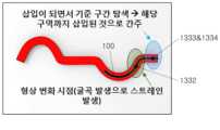
초기 삽입 구간 이전에는 스트레인 변화 또는 형상 변화가 없거나 거의 없는 반면 초기 삽입 구간 이후에는 스트레인 변화 또는 형상 변화가 상대적으로 크게 발생하므로, 상기 대상 구조물의 일부분인 초기 삽입 구간 자체가 곧바로 기준 구간으로 사용된다.Before the initial insertion section, there is little or no strain change or shape change, whereas after the initial insertion section, a relatively large strain or shape change occurs. Therefore, the initial insertion section itself, which is part of the target structure, is directly used as the reference section.
삽입 장치(100)의 센싱부(133)가 이러한 기준 구간을 통과하는지에 따라 스트레인 변화 값이 0 또는 다른 값으로 감지된다.Depending on whether the
측정 장치(200)는 스트레인 정보를 수신하여 특정 센싱부(133)가 기준 구간을 탈출하거나, 또는 적어도 하나의 센싱부(133)가 기준 구간 및/또는 다른 선형 형상 구간에 위치하도록 삽입 장치(100)가 삽입되는 것을 관측한다.The measuring
상기 측정 장치(200)는 스트레인 변화 값이 0으로 감지되는 구간(예컨대, 초기 삽입 구간)에 위치하는 센싱부(133)를 후보 센싱부(1333)로 선별한다. 도 3에서 후보 센싱부(1333)는 기준 구간에 위치한 센싱부(133)이다. 도 4에서 후보 센싱부(1333)는 기준 구간 및 다른 선형 형상 구간에 위치한 센싱부(133)이다. 직전에는 기준 구간에 위치하였으나 삽입이 계속 진행됨에 따라 기준 구간을 통과한 센싱부(133)는 탈출 센싱부(1332)로 지칭된다.The measuring
상기 측정 장치(200)는 기준 구간, 탈출 센싱부(1332)에 기초하여 후보 센싱부(1333)로부터 대상 센싱부(1334)를 선별한다.The
상기 측정 장치(200)는 상기 대상 센싱부(1334)와 주변 센싱부(133) 간의 간격에 기초하여 삽입 길이를 산출한다.The
상기 측정 장치(200)는 기준 구간 중 일부 또는 전부에만 삽입 장치(100)가 삽입된 경우, 삽입 장치(100)는 기준 구간에 삽입된 것으로 간주하여 현재의 삽입 길이를 초기 선형 구간에 대응하는 길이만큼으로 측정한다.When the
측정 장치(200)는, 도 4에 도시된 서로 다른 선형 형상 구간 중에서 삽입 단으로부터 원격 위치한 다른 선형 형상 구간에 삽입되어 있는 삽입 장치(100)의 일부 길이를, 삽입 길이를 업데이트하기 위해 사용하지 않는다. 측정 장치(200)는 서로 다른 선형 형상 구간 중에서 기준 구간에 삽입되어 있는 삽입 장치(100)의 다른 일부 길이를, 삽입 길이를 업데이트하기 위해 사용한다.The measuring
또한, 측정 장치(200)는 삽입이 계속됨으로써 대상 구조물의 내부 구조에서 센싱부(133)의 위치가 계속 변화하면, 새롭게 기준 구간에 삽입된 부분을 관측하여 삽입 길이를 업데이트한다.In addition, when the position of the
이와 같이 기준 구간 및 탈출 센싱부(1332)를 활용한 측정 장치(200)의 동작에 대해서는 아래의 도 7 및 도 8 등을 참조해 보다 상세히 서술한다.In this way, the operation of the
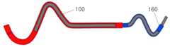
특정 실시예들에서, 상기 삽입 장치(100)는 보조 부리(150, 160)를 더 포함할 수도 있다. 보조 부리(150, 160)는 삽입 장치(100)가 삽입될 대상 구조물의 삽입 단에 결합하도록 구성된다.In certain embodiments, the
보조 부리(150, 160)는 기준 구간에 대응한, 대상 구조물의 내부 구조와 다른 추가 삽입 구조를 제공하는 구조를 가진다. 상기 보조 부리(150, 160)는 대상 구조물의 내부 경로가 기준 구간을 활용 가능한 부분을 포함하지 않는 경우 기준 구간을 제공한다.The
도 5는, 본 출원의 다른 일 실시예에 따른, 보조 부리(holder)를 갖는 삽입 장치가 삽입된 상태 하의 구조물의 단면도이다.5 is a cross-sectional view of a structure in a state in which an insertion device having an auxiliary holder is inserted according to another embodiment of the present application.
도 5를 참조하면, 상기 보조 부리(150)는 몸체(110)가 삽입 가능한 내부 구조를 가지며, 선형 기준 구간을 제공한다. 상기 보조 부리(150)는 일 축을 따라 연장된 선형 형상을 가지며, 내부 구조는 상기 선형 형상에 대응한다. 예를 들어, 도 5에 도시된 것처럼 보조 부리(150)는 선형 원통형 몸체를 가질 수도 있다.Referring to FIG. 5 , the
상기 보조 부리(150)를 통해 기준 구간에 대응한 삽입 구조 부분을 갖지 않는 대상 구조물에 삽입되는 삽입 장치(100)의 삽입 길이를 산출할 수도 있다.An insertion length of the
도 6은, 본 출원의 또 다른 일 실시예에 따른, 보조 부리를 갖는 삽입 장치가 삽입된 상태 하의 구조물의 단면도이다.6 is a cross-sectional view of a structure in a state in which an insertion device having an auxiliary beak is inserted according to another embodiment of the present application.
도 6의 보조 부리(160)는 도 5의 보조 부리(150)와 유사하므로, 차이점을 위주로 서술한다.Since the
도 6을 참조하면, 보조 부리(160)는 몸체(110)가 삽입 가능한 내부 구조를 가지며, 비-선형 기준 구간을 제공한다.Referring to FIG. 6 , the
대상 구조물의 삽입 단에서의 초기 선형 구간이 상대적으로 길 경우, 이 초기 선형 구간을 기준 구간으로 곧바로 활용하면 삽입 길이를 정확히 측정하는데 어려움이 있다.If the initial linear section at the insertion end of the target structure is relatively long, it is difficult to accurately measure the insertion length if the initial linear section is directly used as a reference section.
삽입 장치(100)가 비-선형 보조 부리(160)를 통해 대상 구조물 내부에 삽입되면, 비-선형 보조 부리(160)를 통과하는 것을 전/후로 비-선형 형상으로 변형되었던 몸체(110)가 선형 형상으로 변형된다. 즉, 비-선형 보조 부리(160)는 스트레인 변화 값이 임의의 값으로부터 0으로 되는 기준 구간을 제공한다.When the
일 실시예에서, 보조 부리(160)는 삽입 장치(100)가 대상 구조물의 내부 구조에 보다 용이하게 삽입되는 비-선형 삽입 구조를 형성할 수도 있다.In one embodiment, the
상기 보조 부리(160)는 비-선형 형상을 가지며, 내부 구조는 상기 비-선형 형상에 대응한다. 이러한 비-선형 형상은 삽입 단의 연장 방향이 타 단으로부터 평행하지 않게 연장됨으로써, 삽입 단이 선형 형상인 대상 구조물에 삽입 장치(100)가 직접 삽입되는 경우 보다 보조 부리(160)를 통해 삽입되는 것이 보다 용이하게 한다. 예를 들어, 도 6에 도시된 것처럼 보조 부리(160)는 보조 부리(160)의 일 단과 타 단 사이에 곡률형 내부 구조를 적어도 부분적으로 가질 수도 있다.The
이러한 보조 부리(160)는 특정한 대상 구조물 및 특정 상황에 대해서만 활용될 수도 있다.This
상기 측정 장치(200)가 본 명세서에 서술되지 않은 다른 구성요소를 포함할 수도 있다는 것이 통상의 기술자에게 명백할 것이다. 예를 들어, 측정 장치(200)는 네트워크 인터페이스, 데이터 엔트리를 위한 입력 장치, 및 디스플레이, 인쇄 또는 데이터 표시를 위한 다른 출력 장치를 포함하는, 본 명세서에 서술된 동작에 필요한 다른 하드웨어 요소를 포함할 수도 있다.It will be apparent to those skilled in the art that the
본 출원의 다른 일 측면에 따른 스트레인 변화 또는 형상 변화를 이용하여 삽입 길이를 측정하는 방법은 하나 이상의 프로세서에 의해 수행될 수도 있다. 예를 들어, 스트레인 변화 또는 형상 변화를 이용하여 삽입 길이를 측정하는 방법은 도 1의 삽입 장치(100)와 상호작용하는 측정 장치(200)에 의해 수행될 수도 있다. 이하, 설명의 명료성을 위해, 도 1의 측정 장치(200)에 의해 수행되는 실시예들로 스트레인 변화 또는 형상 변화를 이용하여 삽입 길이를 측정하는 방법을 보다 상세히 서술한다.A method of measuring an insertion length using a strain change or a shape change according to another aspect of the present application may be performed by one or more processors. For example, a method of measuring an insertion length using a strain change or a shape change may be performed by a
도 7은, 본 출원의 일 실시예에 따른, 스트레인 변화 또는 형상 변화를 이용하여 삽입 길이를 측정하는 방법의 흐름도이다.7 is a flowchart of a method of measuring an insertion length using a strain change or a shape change according to an embodiment of the present application.
도 7을 참조하면, 스트레인 변화 또는 형상 변화를 이용하여 삽입 길이를 측정하는 방법(이하, 삽입 길이 측정 방법)은: 대상 구조물에 삽입된 삽입 장치(100)의 감지 정보를 획득하는 단계(S710)를 포함한다. 상기 감지 정보는 스트레인 정보 및/또는 형상 정보를 포함한다.Referring to FIG. 7 , a method of measuring an insertion length using a strain change or shape change (hereinafter referred to as an insertion length measurement method) includes: acquiring detection information of the
일 실시예에서, 삽입 장치(100)가 복수의 센싱부(133)를 포함할 경우, 각 센싱부(133)별 감지 정보를 획득할 수도 있다(S710). 각 센싱부(133)별 감지 정보는 해당 센싱부(133)의 순번과 같은 식별 정보를 더 포함할 수도 있다.In one embodiment, when the
상기 삽입 길이 측정 방법은: 탈출 센싱부(1332)를 지정하는 단계(S720)를 포함한다.The method for measuring the insertion length includes: designating the escape sensing unit 1332 (S720).
기준 구간이 선형 형상일 경우, 탈출 센싱부(1332)는 이전에 선형 형상 구간에 위치하였으나 현재는 그렇지 않은, 이전 선형 형상 위치(previous linear shape position)에 있는 센싱부(133)를 지칭한다. 상기 탈출 센싱부(1332)는 기준 구간이 아닌 곳에 위치한 센싱부(133) 중 가장 가까운 센싱부(133)일 수도 있다.When the reference section is a linear shape, the
측정 장치(200)는 감지 정보(예컨대, 스트레인 변화)에 기초하여 탈출 센싱부(1332)를 지정할 수도 있다.The
탈출 센싱부(1332)의 지정은 센싱부(133)의 순번을 선택함으로써 수행될 수도 있다. 예를 들어, 아직 기준 구간을 벗어난 센싱부(133)가 없는 삽입 초기 상태에서, 초기 탈출 센싱부(1332)의 순번은 0의 값으로 지정될 수도 있다(S720).Designation of the
상기 삽입 길이 측정 방법은: 삽입된 삽입 장치(100)에서 적어도 하나의 후보 센싱부(1333)를 선별하는 단계(S730)를 포함한다.The insertion length measuring method includes: selecting at least one
후보 센싱부(1333)는 삽입된 현재 상태에서 기준 구간에 위치하는 센싱부(133)를 지칭한다. 기준 구간이 선형 형상일 경우, 후보 센싱부(1333)는 현재 선형 형상 위치(Current Linear Shape Position)를 갖는 센싱부(133)이다.The
일 실시예에서, 적어도 하나의 후보 센싱부(1333)를 선별하는 단계(S730)는, (예컨대, 측정 장치(200)에 의해) 감지 정보 내 스트레인 정보의 값 또는 형상 정보의 값의 변화량이 상대적으로 작은 것으로 감지하는 적어도 하나의 센싱부(133)를 후보 센싱부(1333)로 선별하는 것일 수도 있다.In one embodiment, in the step of selecting at least one candidate sensing unit 1333 (S730), the change in the value of strain information or shape information in the sensing information (eg, by the measuring device 200) is relative. It may also be to select at least one
스트레인 정보의 값 또는 형상 정보의 값의 변화량이 0일 경우, 해당 정보를 감지한 센싱부(133)를 후보 센싱부(1333)로 선별할 수도 있다(S730).When the amount of change in the value of the strain information or the value of the shape information is 0, the
상기 후보 센싱부(1333)는 기준 구간에 위치한 적어도 하나의 센싱부(133)만을 포함하거나, 기준 구간 및 다른 선형 구간에 위치한 복수의 센싱부(133)를 포함할 수도 있다.The
상기 삽입 길이 측정 방법은: 탈출 센싱부(1332) 및 후보 센싱부(1333)에 기초하여 삽입 길이를 계산하기 위한 적어도 하나의 대상 센싱부(1334)를 선별하는 단계(S740)를 포함한다.The insertion length measuring method includes: selecting at least one
일 실시예에서, 적어도 하나의 대상 센싱부(1334)를 선별하는 단계(S740)는: 선별된 후보 센싱부(1333) 중 적어도 하나의 후보 센싱부(1333)와 탈출 센싱부(133) 간의 위치 차이를 계산하는 단계(S741); 및 미리 설정된 임계 값이 단계(S741)에서 계산된 위치 차이의 값 보다 보다 큰 후보 센싱부(1333)를 대상 센싱부(1334)로 선별하는 단계(S745)를 포함할 수도 있다.In one embodiment, the step of selecting at least one target sensing unit 1334 (S740) is: a position between at least one
일 실시예에서, 센싱부(1332, 1333) 간의 위치 차이는 각 센싱부(1332, 1333) 간의 순번 차이에 대응할 수도 있다.In one embodiment, the difference in position between the
일 실시예에서, 기준 구간이 선형 형상일 경우, 위치 차이는 PLSP와 CLSP 간의 차이(DLSP, Difference between PLSP and CLSP)로 지칭될 수도 있다. 위치 차이 DLSP는 다음의 수학식을 통해 산출될 수도 있다(S741).In one embodiment, when the reference interval has a linear shape, the position difference may be referred to as a difference between PLSP and CLSP (DLSP). The position difference DLSP may be calculated through the following equation (S741).

여기서, CLSPn은 n번째 후보 센싱부(1333)의 순번을 나타내고 PLSP는 탈출 센싱부(1332)의 순번을 나타낸다.Here, CLSPn represents the order of the n-th
단계(S741)에서 산출된 위치 차이 DLSP의 값은 미리 설정된 임계 값과 비교된다(S745). 전술한 바와 같이, 단계(S730)에서 선별된 후보 센싱부(1333)는 기준 구간 외부의 다른 선형 구간에 있는 센싱부(133)를 포함할 수도 있다. 미리 설정된 임계 값을 사용하여 기준 구간에 있는 후보 센싱부(1333)만이 대상 센싱부(1334)로 선별된다(S745).The value of the position difference DLSP calculated in step S741 is compared with a preset threshold value (S745). As described above, the
상기 임계 값(MThr)은 기준 구간에 있는 후보 센싱부(1333)만을 대상 센싱부(1334)로 선별하기 위해 미리 설정된 값으로서, 기준 구간 내에 배치 가능한 센싱부(133)의 수일 수도 있다. 상기 임계 값은 센싱부(133) 간의 간격 및 기준 구간의 길이에 기초하여 설정된다.The threshold value (MThr ) is a preset value for selecting only the
일 실시예에서, 상기 임계 값은 센싱부(133) 간의 간격 중 최대 간격 및 기준 구간의 길이에 기초하여 설정될 수도 있다. 예를 들어, 도 2의 27번째 센싱부(133) 및 28번째 센싱부(133) 간의 간격(예컨대, 54mm)이 최대 간격이고 기준 구간이120mm일 경우, 임계 값은 2로 설정될 수도 있다.In one embodiment, the threshold value may be set based on the maximum distance among the distances between the sensing
일 실시예에서, 후보 센싱부(1333)는 배치 순번에 따라 임계 값과 비교될 수도 있다(S741 및 S745). 제1 후보 센싱부(1333)(즉, n=1)와 탈출 센싱부(1332) 간의 위치 차이가 계산되고(S741) 임계 값이 계산된 위치 차이의 값 보다 크지 않다면 (즉, 계산된 위치 차이의 값이 임계 값 보다 크면) 상기 제1 후보 센싱부(1333)는 대상 센싱부(1334)로 선별되지 않고 삽입 길이를 계산하는데 사용되지 않는다(S745). 이어서, 제1 후보 센싱부(1333)의 다음 순번을 갖는 제2 후보 센싱부(1333)와 탈출 센싱부(1332) 간의 위치 차이가 계산되고(S741) 임계 값이 계산된 위치 차이의 값 보다 크다면 상기 제2 후보 센싱부(1333)는 대상 센싱부(1334)로 선별되고 삽입 길이를 계산하는데 사용된다(S745).In one embodiment, the
탈출 센싱부(1332)와 비교되는 후보 센싱부(1333)의 순번 변경은 단계(S730)에서 선별된 후보 센싱부(133)의 순번에 따라 수행된다.The order of the
상기 삽입 길이 측정 방법은: 선별된 대상 센싱부(1334)에 기초하여 삽입 길이를 산출하는 단계(S750)를 포함한다.The method for measuring the insertion length includes: calculating the insertion length based on the selected target sensing unit 1334 (S750).
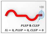
일 실시예에서, 탈출 센싱부(1332)의 값이 0인 경우, 즉 삽입 장치(100)가 기준 구간에만 삽입되어 있는 경우, 기준 구간의 길이가 삽입 길이로 취급된다.In one embodiment, when the value of the
일 실시예에서, 상기 삽입 장치가 기준 구간을 통과하여 삽입된 경우, 대상 센싱부(1334)와 주변 센싱부(133) 간의 간격에 삽입 길이를 산출하는 단계(S750)를 포함한다.In one embodiment, when the insertion device is inserted through the reference section, calculating an insertion length in the distance between the
일 실시예에서, 대상 센싱부(1334) 및 상기 대상 센싱부(1334) 보다 먼저 삽입된 직전 센싱부(133) 간의 간격에 기초하여 삽입 길이가 산출될 수도 있다(S750).In one embodiment, the insertion length may be calculated based on the distance between the
일 실시예에서, 삽입 길이(IL)는 다음의 수학식에 기초하여 산출될 수도 있다(S750).In one embodiment, the insertion length (IL) may be calculated based on the following equation (S750).

여기서, n은 대상 센싱부(1334) 각각의 순번, 및 m은 대상 센싱부(1334)의 수를 나타낸다.Here, n represents the order of each
상기 삽입 길이 측정 방법은: 삽입 장치(100)가 대상 구조물에 삽입되는 것이 완료되지 않는다면, 삽입 장치(100)의 삽입을 계속 진행하여 삽입 길이를 업데이트하는 단계(S760)를 포함한다. 삽입이 완료되면, 산출된 삽입 길이가 전체 삽입 길이로 결정된다.The insertion length measurement method includes: if the insertion of the
일 실시예에서, 삽입 장치(100)의 삽입을 계속 진행하여 삽입 길이를 업데이트하는 단계(S760)는, 탈출 센싱부(1332)를 지정하기 위해 기존 탈출 센싱부(1332)를 업데이트하는 단계(S760); 및 업데이트된 탈출 센싱부(1332)를 기초로 대상 센싱부(1334)를 추가로 선별하는 단계(SS730, 740)를 포함할 수도 있다.In one embodiment, the step of updating the insertion length by continuing the insertion of the insertion device 100 (S760) is the step of updating the existing
일 실시예에서, 기존의 탈출 센싱부(1332)는 대상 센싱부(1334) 중에서 가장 나중에 삽입된 센싱부(133), 즉 가장 순번이 높은 대상 센싱부(1334)로 업데이트된다(S760). 삽입이 계속되면 가장 나중에 삽입된 센싱부(1334)가 결국에 가장 최신의 탈출 센싱부(1332)의 위치로 이동하기 때문이다.In one embodiment, the existing
업데이트된 탈출 센싱부(1332)의 값이 적용되어 단계(S740)가 수행된다.The updated value of the
최신 탈출 센싱부(1132)의 위치로 이동한 삽입 장치(100)에 대해서, 후보 센싱부(1333)가 재-선별될 수도 있다(S730).For the
일 실시예에서, 상기 대상 센싱부(1334)를 추가로 선별하는 단계(S740)는: 적어도 하나의 후보 센싱부(1333)와 업데이트된 탈출 센싱부(1332) 간의 위치 차이를 계산하는 단계(S741); 및 미리 설정된 임계 값이 단계(S741)에서 계산된 위치 차이의 값 보다 보다 큰 후보 센싱부(1333)를 대상 센싱부(1334)로 선별하는 단계(S745)를 포함할 수도 있다.In an embodiment, the step of additionally selecting the target sensing unit 1334 (S740) is: calculating a positional difference between at least one
자세한 내용은 탈출 센싱부(1332)가 업데이트되기 이전의 실시예들에서 서술하였는 바, 자세한 설명은 생략한다.Details have been described in the previous embodiments before the
도 8a 내지 도 8c는, 본 출원의 일 실시예에 따른, 삽입이 진행되는 동안 각 상태별 대상 노드 및 탈출 센싱부를 도시한다.8A to 8C illustrate a target node and an exit sensing unit for each state while insertion is in progress, according to an embodiment of the present application.
도 8에서 기준 구간은 둘 이상의 센싱부(133)가 동시에 위치하지 않는 구간 길이를 갖는 것으로 가정해보자. 즉, 임계 값(MThr)은 1로 설정된다.Assume that the reference section in FIG. 8 has a section length in which two or
도 8a를 참조하면, 삽입 장치(100)가 기준 구간에만 삽입되어 있으므로, 삽입 길이는 기준 구간의 길이에 매칭한다.Referring to FIG. 8A , since the
도 8b를 참조하면, 삽입 장치(100)가 기준 구간을 벗어난 비-선형 구간까지 삽입된 상태이다. 7번째 센싱부(133)가 대상 센싱부(1334)로 선별된다(S741 및 745). 그러면, 상기 수학식 2에 의해 계산된 도 8b에서의 삽입 길이는 7번째 센싱부(133)까지의 길이에 매칭한다.Referring to FIG. 8B , the
도 8c를 참조하면, 삽입 장치(100)가 기준 구간과 다른 선형 구간까지 삽입된 상태이다. 단계(S730)에서 후보 센싱부(1333)는 1번째 센싱부(133), 2번째 센싱부(133), 및 m번째 센싱부(133)를 포함한다. 단계(S741 및 S745)를 통해 1번째 센싱부(133) 및 2번째 센싱부(133)는 대상 센싱부(1334)에서 제외된다. 15번째 센싱부(133)가 대상 센싱부(1334)로 선별된다(S741 및 745). 그러면 상기 수학식 2에 의해 계산된 도 8c에서의 삽입 길이는 15번째 센싱부(133)까지의 길이에 매칭한다.Referring to FIG. 8C , the
이와 같이 (예컨대, 측정 장치(200)에 의해 수행되는) 삽입 길이 측정 방법은 삽입 초기 부분의 선형 형상 구간을 모니터링하면서 스트레인 변화(또는 형상 변화)가 발생한 부분을 기점으로 새롭게 삽입된 길이를 측정할 수 있고, 결국 전체 삽입 길이를 산출할 수도 있다. 이 과정에서 형상 정보를 적분하는 것과 같은 복잡한 연산이 수행되지 않고, 상대적으로 간단한 연산으로 전체 삽입 길이를 보다 신속히 산출 가능하다.In this way, the insertion length measuring method (eg, performed by the measuring device 200) measures the newly inserted length starting from the part where the strain change (or shape change) occurs while monitoring the linear shape section of the initial insertion part. , and eventually calculate the total insertion length. In this process, a complicated calculation such as integrating shape information is not performed, and the total insertion length can be calculated more quickly with a relatively simple calculation.
특히, 삽입 길이 측정 방법은 중간에 다른 선형 형상 구간을 갖는 대상 구조물에 삽입 장치(100)가 삽입되어도 정확하고 간편하게 전체 삽입 길이를 산출할 수 있다.In particular, the insertion length measurement method can accurately and conveniently calculate the total insertion length even when the
이상에서 설명한 실시예들에 따른 스트레인 변화 또는 형상 변화를 이용한 삽입 길이 측정 방법은 적어도 부분적으로 컴퓨터 프로그램으로 구현되어, 컴퓨터로 읽을 수 있는 기록매체에 기록될 수 있다. 예를 들어, 프로그램 코드를 포함하는 컴퓨터-판독가능 매체로 구성되는 프로그램 제품과 함께 구현되고, 이는 기술된 임의의 또는 모든 단계, 동작, 또는 과정을 수행하기 위한 프로세서에 의해 실행될 수 있다.The insertion length measurement method using strain change or shape change according to the embodiments described above may be at least partially implemented as a computer program and recorded on a computer-readable recording medium. For example, implemented together with a program product consisting of a computer-readable medium containing program code, which may be executed by a processor to perform any or all steps, operations, or processes described.
상기 컴퓨터는 데스크탑 컴퓨터, 랩탑 컴퓨터, 노트북, 스마트 폰, 또는 이와 유사한 것과 같은 컴퓨팅 장치일 수도 있고 통합될 수도 있는 임의의 장치일 수 있다. 컴퓨터는 하나 이상의 대체적이고 특별한 목적의 프로세서, 메모리, 저장공간, 및 네트워킹 구성요소(무선 또는 유선 중 어느 하나)를 가지는 장치다. 상기 컴퓨터는 예를 들어, 마이크로소프트의 윈도우와 호환되는 운영 체제, 애플 OS X 또는 iOS, 리눅스 배포판(Linux distribution), 또는 구글의 안드로이드 OS와 같은 운영체제(operating system)를 실행할 수 있다.The computer may be any device that may be integrated into or may be a computing device such as a desktop computer, laptop computer, notebook, smart phone, or the like. A computer is a device that has one or more alternative and special purpose processors, memory, storage, and networking components (whether wireless or wired). The computer may run, for example, an operating system compatible with Microsoft's Windows, Apple's OS X or iOS, a Linux distribution, or an operating system such as Google's Android OS.
상기 컴퓨터가 읽을 수 있는 기록매체는 컴퓨터에 의하여 읽혀질 수 있는 데이터가 저장되는 모든 종류의 기록 장치를 포함한다. 컴퓨터가 읽을 수 있는 기록매체의 예로는 ROM, RAM, CD-ROM, 자기 테이프, 플로피디스크, 광 데이터 저장 장치 등을 포함한다. 또한 컴퓨터가 읽을 수 있는 기록매체는 네트워크로 연결된 컴퓨터 시스템에 분산되어, 분산 방식으로 컴퓨터가 읽을 수 있는 코드가 저장되고 실행될 수도 있다. 또한, 본 실시예를 구현하기 위한 기능적인 프로그램, 코드 및 코드 세그먼트(segment)들은 본 실시예가 속하는 기술 분야의 통상의 기술자에 의해 용이하게 이해될 수 있을 것이다. The computer-readable recording medium includes all types of recording devices in which data readable by a computer is stored. Examples of the computer-readable recording medium include ROM, RAM, CD-ROM, magnetic tape, floppy disk, optical data storage device, and the like. In addition, computer-readable recording media may be distributed in computer systems connected through a network, and computer-readable codes may be stored and executed in a distributed manner. In addition, functional programs, codes, and code segments for implementing this embodiment can be easily understood by those skilled in the art to which this embodiment belongs.
이상에서 살펴본 본 발명은 도면에 도시된 실시예들을 참고로 하여 설명하였으나 이는 예시적인 것에 불과하며 당해 분야에서 통상의 지식을 가진 자라면 이로부터 다양한 변형 및 실시예의 변형이 가능하다는 점을 이해할 것이다. 그러나, 이와 같은 변형은 본 발명의 기술적 보호범위 내에 있다고 보아야 한다. 따라서, 본 발명의 진정한 기술적 보호범위는 첨부된 특허청구범위의 기술적 사상에 의해서 정해져야 할 것이다.The present invention reviewed above has been described with reference to the embodiments shown in the drawings, but this is only exemplary, and those skilled in the art will understand that various modifications and variations of the embodiments are possible therefrom. However, such modifications should be considered within the technical protection scope of the present invention. Therefore, the true technical protection scope of the present invention should be determined by the technical spirit of the appended claims.
100 : 삽입 장치
110: 몸체
130: 센싱부
200: 측정 장치
150, 160: 보조 부리100: insertion device
110: body
130: sensing unit
200: measuring device
150, 160: auxiliary beak
Claims (15)
Translated fromKorean대상 구조물의 내부 구조에 삽입되는 삽입 장치에 포함된 적어도 하나의 센싱부로부터 감지 정보를 획득하는 단계;
감지 정보에 기초하여 기준 구간을 벗어나면서 가장 가까운 탈출 센싱부를 지정하는 단계 - 상기 기준 구간은, 상기 기준 구간의 통과 전후로 삽입 장치의 몸체의 형상이 변화하거나 스트레인이 변화하는 구간임;
상기 감지 정보에 기초하여 기준 구간에 위치한 적어도 하나의 후보 센싱부를 선별하는 단계;
상기 탈출 센싱부 및 후보 센싱부에 기초하여 삽입 길이를 계산하기 위한 적어도 하나의 대상 센싱부를 선별하는 단계; 및
선별된 대상 센싱부에 기초하여 삽입 길이를 산출하는 단계를 포함하는 방법.
In the method of measuring the insertion length using a strain change or a shape change, performed by at least one processor,
obtaining sensing information from at least one sensing unit included in an insertion device inserted into an internal structure of a target structure;
Designating the nearest escape sensing unit while leaving the reference section based on the detection information - The reference section is a section in which the shape or strain of the body of the insertion device changes before and after passing the reference section;
selecting at least one candidate sensing unit located in a reference section based on the detection information;
selecting at least one target sensing unit for calculating an insertion length based on the escape sensing unit and the candidate sensing unit; and
A method comprising calculating an insertion length based on the selected target sensing unit.
선별된 후보 센싱부 중 적어도 하나의 후보 센싱부와 탈출 센싱부 간의 위치 차이를 계산하는 단계; 및
미리 설정된 임계 값이 계산된 위치 차이의 값 보다 보다 큰 후보 센싱부를 대상 센싱부로 선별하는 단계를 포함하는 것을 특징으로 하는 방법.
The method of claim 1 , wherein selecting the at least one target sensing unit comprises:
calculating a positional difference between at least one candidate sensing unit and an escape sensing unit among the selected candidate sensing units; and
and selecting, as a target sensing unit, a candidate sensing unit having a predetermined threshold value greater than the calculated position difference value.
상기 위치 차이는 다음의 수학식을 통해 산출되며,
[수학식]

여기서, CLSPn은 n번째 후보 센싱부의 순번을 나타내고 PLSP는 탈출 센싱부의 순번을 나타내는 것을 특징으로 하는 방법.
According to claim 2,
The position difference is calculated through the following equation,
[mathematical expression]
Here, CLSPn represents the order of the n-th candidate sensing unit and PLSP represents the order of the escape sensing unit.
상기 임계 값은 센싱부 간의 간격 및 기준 구간의 길이에 기초하여 설정되는 것을 특징으로 하는 방법.
According to claim 2,
The method characterized in that the threshold value is set based on the distance between the sensing units and the length of the reference section.
상기 삽입 장치가 기준 구간에만 삽입되어 있는 경우, 기준 구간의 길이가 삽입 길이로 산출되는 것을 특징으로 하는 방법.
According to claim 1,
When the insertion device is inserted only in the reference section, the length of the reference section is calculated as the insertion length.
상기 삽입 장치가 기준 구간을 통과하여 삽입된 경우, 상기 삽입 길이(IL)는 다음의 수학식에 기초하여 산출되며,
[수학식]

여기서, n은 대상 센싱부 각각의 순번을 나타내고, m은 대상 센싱부의 수를 나타내는 것을 특징으로 하는 방법.
According to claim 1,
When the insertion device is inserted through the reference section, the insertion length (IL) is calculated based on the following equation,
[mathematical expression]
Here, n represents the order of each target sensing unit, and m represents the number of target sensing units.
상기 감지 정보는 각 센싱부별로 생성되며,
각 센싱부별 감지 정보는 스트레인 정보, 형상 정보 및 이들의 조합 중 어느 하나, 및 해당 센싱부의 식별 정보를 포함하고,
상기 기준 구간은 스트레인 변화 또는 형상 변화가 상대적으로 적은 구간인 것을 특징으로 하는 방법.
According to claim 1,
The detection information is generated for each sensing unit,
The sensing information for each sensing unit includes strain information, shape information, any combination thereof, and identification information of the corresponding sensing unit,
The method characterized in that the reference section is a section in which the strain change or shape change is relatively small.
상기 적어도 하나의 대상 센싱부를 선별하는 단계는,
후보 센싱부에 기초하여 계산된 위치 차이의 값이 미리 설정된 임계 값 보다 큰 경우 해당 후보 센싱부 다음 순번으로 삽입될, 다음 후보 센싱부와 상기 탈출 센싱부 간의 위치 차이를 계산하는 단계;를 더 포함하되,
미리 설정된 임계 값이 상기 다음 후보 센싱부에 기초하여 계산된 위치 차이의 값 보다 클 경우, 상기 다음 후보 센싱부를 대상 센싱부로 결정하는 것을 특징으로 하는 방법.
According to claim 2,
The step of selecting the at least one target sensing unit,
If the value of the position difference calculated based on the candidate sensing unit is greater than a preset threshold, calculating a position difference between the next candidate sensing unit to be inserted in the next sequence of the corresponding candidate sensing unit and the escape sensing unit; further comprising but
and determining the next candidate sensing unit as a target sensing unit when a predetermined threshold value is greater than a value of a position difference calculated based on the next candidate sensing unit.
삽입이 완료되지 않으면, 탈출 센싱부는 대상 센싱부 중에서 가장 나중에 삽입된 대상 센싱부로 업데이트되는 것을 특징으로 하는 방법.
According to claim 1,
If the insertion is not completed, the prolapse sensing unit is updated to a target sensing unit inserted most recently among the target sensing units.
상기 대상 센싱부를 추가로 선별하는 단계는: 적어도 하나의 대상 센싱부와 업데이트된 탈출 센싱부 간의 위치 차이를 계산하는 단계; 및 미리 설정된 임계 값이 단계에서 계산된 위치 차이의 값 보다 보다 큰 후보 센싱부를 대상 센싱부로 선별하는 단계를 더 포함하는 것을 특징으로 하는 방법.
The method of claim 9,
The additionally selecting the target sensing unit may include: calculating a position difference between at least one target sensing unit and the updated escape sensing unit; and selecting, as the target sensing unit, a candidate sensing unit having a predetermined threshold value greater than the value of the position difference calculated in the step.
A computer-readable recording medium in which a program for performing the method of measuring an insertion length using a train change or shape change according to any one of claims 1 to 10 is recorded.
대상 구조물의 내부 구조에 삽입되기 위한 가요성 몸체; 및
스트레인 변화 및 형상 변화 중 하나 이상을 포함한 감지 정보를 생성하는 센서를 포함하고,
상기 센서는 복수의 지점에서의 감지 정보를 생성하는 복수의 센싱부를 포함하는 것을 특징으로 하는 삽입 장치.
In the insertion device connected to the measuring device, inserted into the internal structure of the target structure,
a flexible body to be inserted into the internal structure of the target structure; and
A sensor for generating sensing information including at least one of a strain change and a shape change;
The insertion device characterized in that the sensor comprises a plurality of sensing units for generating sensing information at a plurality of points.
상기 몸체가 삽입되어 대상 구조물 내부로 진행 가능한 내부 구조를 갖는, 대상 구조물의 삽입 단에 결합되는 제1 보조 부리를 더 포함하며,
상기 제1 보조 부리의 내부 구조는 선형 형상을 가지는 것으로서, 선형 기준 구간을 제공하는 것을 특징으로 하는 삽입 장치.
The method of claim 12,
Further comprising a first auxiliary beak coupled to the insertion end of the target structure, the body having an internal structure capable of being inserted into the target structure,
The insertion device, characterized in that the internal structure of the first auxiliary beak has a linear shape, providing a linear reference section.
상기 몸체가 삽입되어 대상 구조물 내부로 진행 가능한 내부 구조를 갖는, 대상 구조물의 삽입 단에 결합되는 제2 보조 부리를 더 포함하며,
상기 제2 보조 부리의 내부 구조는 비-선형 형상을 가지는 것으로서, 비-선형 기준 구간을 제공하는 것을 특징으로 하는 삽입 장치.
The method of claim 12,
Further comprising a second auxiliary beak coupled to the insertion end of the target structure having an internal structure in which the body can be inserted and progressed into the target structure,
The insertion device, characterized in that the internal structure of the second auxiliary beak has a non-linear shape, providing a non-linear reference section.
상기 삽입 장치에 연결되는 측정 장치는,
상기 센서의 반사광을 전기 신호로 변환하는 검출부;
상기 전기 신호를 신호 데이터로 변환하여 상기 감지 정보를 데이터화하는 데이터 수집부; 및
신호 데이터를 처리하여 삽입 장치의 삽입 길이를 산출하는 연산부를 포함하는 것을 특징으로 하는 삽입 장치.The method of claim 12, wherein the sensor is an FBG sensor and generates sensing information expressed as a wavelength of reflected light,
A measuring device coupled to the insertion device comprises:
a detection unit that converts the reflected light of the sensor into an electrical signal;
a data collection unit converting the electric signal into signal data and converting the sensing information into data; and
An insertion device comprising a calculation unit that processes signal data to calculate an insertion length of the insertion device.
Priority Applications (1)
| Application Number | Priority Date | Filing Date | Title |
|---|---|---|---|
| KR1020210186929AKR102681315B1 (en) | 2021-12-24 | 2021-12-24 | Method for measruing inserting length using shape of insertion device and insertion device for the same |
Applications Claiming Priority (1)
| Application Number | Priority Date | Filing Date | Title |
|---|---|---|---|
| KR1020210186929AKR102681315B1 (en) | 2021-12-24 | 2021-12-24 | Method for measruing inserting length using shape of insertion device and insertion device for the same |
Publications (2)
| Publication Number | Publication Date |
|---|---|
| KR20230097437Atrue KR20230097437A (en) | 2023-07-03 |
| KR102681315B1 KR102681315B1 (en) | 2024-07-05 |
Family
ID=87157257
Family Applications (1)
| Application Number | Title | Priority Date | Filing Date |
|---|---|---|---|
| KR1020210186929AActiveKR102681315B1 (en) | 2021-12-24 | 2021-12-24 | Method for measruing inserting length using shape of insertion device and insertion device for the same |
Country Status (1)
| Country | Link |
|---|---|
| KR (1) | KR102681315B1 (en) |
Citations (8)
| Publication number | Priority date | Publication date | Assignee | Title |
|---|---|---|---|---|
| KR100262837B1 (en) | 1995-06-06 | 2000-09-01 | 스피겔 알렌 제이 | Endovascular measuring apparatus, loading and deployment means |
| US20060013523A1 (en)* | 2004-07-16 | 2006-01-19 | Luna Innovations Incorporated | Fiber optic position and shape sensing device and method relating thereto |
| US20110113852A1 (en)* | 2009-11-13 | 2011-05-19 | Intuitive Surgical, Inc. | Optical fiber shape sensor calibration |
| US20130028554A1 (en)* | 2011-07-29 | 2013-01-31 | Hansen Medical, Inc. | Apparatus and methods for fiber integration and registration |
| US20150192743A1 (en)* | 2008-06-30 | 2015-07-09 | Intuitive Surgical Operations, Inc. | Fixture For Shape-Sensing Optical Fiber In A Kinematic Chain |
| KR20150132145A (en)* | 2013-03-15 | 2015-11-25 | 인튜어티브 서지컬 오퍼레이션즈 인코포레이티드 | Shape sensor systems for tracking interventional instruments and methods of use |
| KR20160120915A (en)* | 2015-04-09 | 2016-10-19 | 한국과학기술연구원 | Multi-functional Sensor assembly |
| JP2017225866A (en)* | 2012-02-03 | 2017-12-28 | インテュイティブ サージカル オペレーションズ, インコーポレイテッド | Steerable flexible needle with embedded shape sensing function |
- 2021
- 2021-12-24KRKR1020210186929Apatent/KR102681315B1/enactiveActive
Patent Citations (8)
| Publication number | Priority date | Publication date | Assignee | Title |
|---|---|---|---|---|
| KR100262837B1 (en) | 1995-06-06 | 2000-09-01 | 스피겔 알렌 제이 | Endovascular measuring apparatus, loading and deployment means |
| US20060013523A1 (en)* | 2004-07-16 | 2006-01-19 | Luna Innovations Incorporated | Fiber optic position and shape sensing device and method relating thereto |
| US20150192743A1 (en)* | 2008-06-30 | 2015-07-09 | Intuitive Surgical Operations, Inc. | Fixture For Shape-Sensing Optical Fiber In A Kinematic Chain |
| US20110113852A1 (en)* | 2009-11-13 | 2011-05-19 | Intuitive Surgical, Inc. | Optical fiber shape sensor calibration |
| US20130028554A1 (en)* | 2011-07-29 | 2013-01-31 | Hansen Medical, Inc. | Apparatus and methods for fiber integration and registration |
| JP2017225866A (en)* | 2012-02-03 | 2017-12-28 | インテュイティブ サージカル オペレーションズ, インコーポレイテッド | Steerable flexible needle with embedded shape sensing function |
| KR20150132145A (en)* | 2013-03-15 | 2015-11-25 | 인튜어티브 서지컬 오퍼레이션즈 인코포레이티드 | Shape sensor systems for tracking interventional instruments and methods of use |
| KR20160120915A (en)* | 2015-04-09 | 2016-10-19 | 한국과학기술연구원 | Multi-functional Sensor assembly |
Also Published As
| Publication number | Publication date |
|---|---|
| KR102681315B1 (en) | 2024-07-05 |
Similar Documents
| Publication | Publication Date | Title |
|---|---|---|
| US11206999B2 (en) | Flexible instrument channel insert for scope with real-time position tracking | |
| US11642031B2 (en) | Medical device insertion and exit information using distributed fiber optic temperature sensing | |
| US11547489B2 (en) | Shape sensing of multiple over-the-wire devices | |
| EP3191800B1 (en) | Detection of surface contact with optical shape sensing | |
| CN217960069U (en) | Elongated multi-core fiber optic instrument for insertion into the body of a patient and related medical systems | |
| EP2846691B1 (en) | System and method for stabilizing optical shape sensing | |
| CN103328922B (en) | Reference markers for origination point identification in optical shape sensing systems | |
| US20190346319A1 (en) | Systems and methods for determining the length of a non-shape-sensed interventional device with a shape-sensed guidewire and determining a state of the guidewire with respect to an interventional device | |
| EP3037056B1 (en) | System for reconstructing a trajectory of an optical fiber | |
| US11344222B2 (en) | Systems and methods for determining the position of a non-shape-sensed guidewire with a shape-sensed catheter and for visualizing the guidewire | |
| KR102681315B1 (en) | Method for measruing inserting length using shape of insertion device and insertion device for the same | |
| US20180344204A1 (en) | Features for optical shape sense enabled device identification | |
| WO2016207163A1 (en) | System and method for registering a structure using fiber-optical realshape data | |
| WO2015092590A1 (en) | System and method for determining the entry point to the body using optical shape sensing | |
| WO2012143883A2 (en) | Visible optical fiber for medical imaging applications |
Legal Events
| Date | Code | Title | Description |
|---|---|---|---|
| PA0109 | Patent application | Patent event code:PA01091R01D Comment text:Patent Application Patent event date:20211224 | |
| PA0201 | Request for examination | ||
| PG1501 | Laying open of application | ||
| E902 | Notification of reason for refusal | ||
| PE0902 | Notice of grounds for rejection | Comment text:Notification of reason for refusal Patent event date:20240129 Patent event code:PE09021S01D | |
| E701 | Decision to grant or registration of patent right | ||
| PE0701 | Decision of registration | Patent event code:PE07011S01D Comment text:Decision to Grant Registration Patent event date:20240405 | |
| PR0701 | Registration of establishment | Comment text:Registration of Establishment Patent event date:20240701 Patent event code:PR07011E01D | |
| PR1002 | Payment of registration fee | Payment date:20240702 End annual number:3 Start annual number:1 | |
| PG1601 | Publication of registration |