KR20230096328A - Power management device and vehicle having the same - Google Patents
Power management device and vehicle having the sameDownload PDFInfo
- Publication number
- KR20230096328A KR20230096328AKR1020210185707AKR20210185707AKR20230096328AKR 20230096328 AKR20230096328 AKR 20230096328AKR 1020210185707 AKR1020210185707 AKR 1020210185707AKR 20210185707 AKR20210185707 AKR 20210185707AKR 20230096328 AKR20230096328 AKR 20230096328A
- Authority
- KR
- South Korea
- Prior art keywords
- voltage
- power
- signal line
- battery
- vehicle
- Prior art date
- Legal status (The legal status is an assumption and is not a legal conclusion. Google has not performed a legal analysis and makes no representation as to the accuracy of the status listed.)
- Pending
Links
Images


Classifications
- G—PHYSICS
- G06—COMPUTING OR CALCULATING; COUNTING
- G06F—ELECTRIC DIGITAL DATA PROCESSING
- G06F1/00—Details not covered by groups G06F3/00 - G06F13/00 and G06F21/00
- G06F1/26—Power supply means, e.g. regulation thereof
- G06F1/28—Supervision thereof, e.g. detecting power-supply failure by out of limits supervision
- G—PHYSICS
- G01—MEASURING; TESTING
- G01R—MEASURING ELECTRIC VARIABLES; MEASURING MAGNETIC VARIABLES
- G01R31/00—Arrangements for testing electric properties; Arrangements for locating electric faults; Arrangements for electrical testing characterised by what is being tested not provided for elsewhere
- G01R31/36—Arrangements for testing, measuring or monitoring the electrical condition of accumulators or electric batteries, e.g. capacity or state of charge [SoC]
- G01R31/392—Determining battery ageing or deterioration, e.g. state of health
- B—PERFORMING OPERATIONS; TRANSPORTING
- B60—VEHICLES IN GENERAL
- B60L—PROPULSION OF ELECTRICALLY-PROPELLED VEHICLES; SUPPLYING ELECTRIC POWER FOR AUXILIARY EQUIPMENT OF ELECTRICALLY-PROPELLED VEHICLES; ELECTRODYNAMIC BRAKE SYSTEMS FOR VEHICLES IN GENERAL; MAGNETIC SUSPENSION OR LEVITATION FOR VEHICLES; MONITORING OPERATING VARIABLES OF ELECTRICALLY-PROPELLED VEHICLES; ELECTRIC SAFETY DEVICES FOR ELECTRICALLY-PROPELLED VEHICLES
- B60L3/00—Electric devices on electrically-propelled vehicles for safety purposes; Monitoring operating variables, e.g. speed, deceleration or energy consumption
- B60L3/0023—Detecting, eliminating, remedying or compensating for drive train abnormalities, e.g. failures within the drive train
- B60L3/0046—Detecting, eliminating, remedying or compensating for drive train abnormalities, e.g. failures within the drive train relating to electric energy storage systems, e.g. batteries or capacitors
- B—PERFORMING OPERATIONS; TRANSPORTING
- B60—VEHICLES IN GENERAL
- B60L—PROPULSION OF ELECTRICALLY-PROPELLED VEHICLES; SUPPLYING ELECTRIC POWER FOR AUXILIARY EQUIPMENT OF ELECTRICALLY-PROPELLED VEHICLES; ELECTRODYNAMIC BRAKE SYSTEMS FOR VEHICLES IN GENERAL; MAGNETIC SUSPENSION OR LEVITATION FOR VEHICLES; MONITORING OPERATING VARIABLES OF ELECTRICALLY-PROPELLED VEHICLES; ELECTRIC SAFETY DEVICES FOR ELECTRICALLY-PROPELLED VEHICLES
- B60L3/00—Electric devices on electrically-propelled vehicles for safety purposes; Monitoring operating variables, e.g. speed, deceleration or energy consumption
- B60L3/12—Recording operating variables ; Monitoring of operating variables
- B—PERFORMING OPERATIONS; TRANSPORTING
- B60—VEHICLES IN GENERAL
- B60R—VEHICLES, VEHICLE FITTINGS, OR VEHICLE PARTS, NOT OTHERWISE PROVIDED FOR
- B60R16/00—Electric or fluid circuits specially adapted for vehicles and not otherwise provided for; Arrangement of elements of electric or fluid circuits specially adapted for vehicles and not otherwise provided for
- B60R16/02—Electric or fluid circuits specially adapted for vehicles and not otherwise provided for; Arrangement of elements of electric or fluid circuits specially adapted for vehicles and not otherwise provided for electric constitutive elements
- B60R16/023—Electric or fluid circuits specially adapted for vehicles and not otherwise provided for; Arrangement of elements of electric or fluid circuits specially adapted for vehicles and not otherwise provided for electric constitutive elements for transmission of signals between vehicle parts or subsystems
- B60R16/0231—Circuits relating to the driving or the functioning of the vehicle
- B60R16/0232—Circuits relating to the driving or the functioning of the vehicle for measuring vehicle parameters and indicating critical, abnormal or dangerous conditions
- B—PERFORMING OPERATIONS; TRANSPORTING
- B60—VEHICLES IN GENERAL
- B60R—VEHICLES, VEHICLE FITTINGS, OR VEHICLE PARTS, NOT OTHERWISE PROVIDED FOR
- B60R16/00—Electric or fluid circuits specially adapted for vehicles and not otherwise provided for; Arrangement of elements of electric or fluid circuits specially adapted for vehicles and not otherwise provided for
- B60R16/02—Electric or fluid circuits specially adapted for vehicles and not otherwise provided for; Arrangement of elements of electric or fluid circuits specially adapted for vehicles and not otherwise provided for electric constitutive elements
- B60R16/03—Electric or fluid circuits specially adapted for vehicles and not otherwise provided for; Arrangement of elements of electric or fluid circuits specially adapted for vehicles and not otherwise provided for electric constitutive elements for supply of electrical power to vehicle subsystems or for
- B60R16/033—Electric or fluid circuits specially adapted for vehicles and not otherwise provided for; Arrangement of elements of electric or fluid circuits specially adapted for vehicles and not otherwise provided for electric constitutive elements for supply of electrical power to vehicle subsystems or for characterised by the use of electrical cells or batteries
- G—PHYSICS
- G01—MEASURING; TESTING
- G01R—MEASURING ELECTRIC VARIABLES; MEASURING MAGNETIC VARIABLES
- G01R19/00—Arrangements for measuring currents or voltages or for indicating presence or sign thereof
- G01R19/0084—Arrangements for measuring currents or voltages or for indicating presence or sign thereof measuring voltage only
- G—PHYSICS
- G01—MEASURING; TESTING
- G01R—MEASURING ELECTRIC VARIABLES; MEASURING MAGNETIC VARIABLES
- G01R19/00—Arrangements for measuring currents or voltages or for indicating presence or sign thereof
- G01R19/165—Indicating that current or voltage is either above or below a predetermined value or within or outside a predetermined range of values
- G01R19/16566—Circuits and arrangements for comparing voltage or current with one or several thresholds and for indicating the result not covered by subgroups G01R19/16504, G01R19/16528, G01R19/16533
- G—PHYSICS
- G01—MEASURING; TESTING
- G01R—MEASURING ELECTRIC VARIABLES; MEASURING MAGNETIC VARIABLES
- G01R19/00—Arrangements for measuring currents or voltages or for indicating presence or sign thereof
- G01R19/25—Arrangements for measuring currents or voltages or for indicating presence or sign thereof using digital measurement techniques
- G01R19/2516—Modular arrangements for computer based systems; using personal computers (PC's), e.g. "virtual instruments"
- G—PHYSICS
- G01—MEASURING; TESTING
- G01R—MEASURING ELECTRIC VARIABLES; MEASURING MAGNETIC VARIABLES
- G01R22/00—Arrangements for measuring time integral of electric power or current, e.g. electricity meters
- G01R22/06—Arrangements for measuring time integral of electric power or current, e.g. electricity meters by electronic methods
- G01R22/061—Details of electronic electricity meters
- G01R22/063—Details of electronic electricity meters related to remote communication
- G—PHYSICS
- G01—MEASURING; TESTING
- G01R—MEASURING ELECTRIC VARIABLES; MEASURING MAGNETIC VARIABLES
- G01R22/00—Arrangements for measuring time integral of electric power or current, e.g. electricity meters
- G01R22/06—Arrangements for measuring time integral of electric power or current, e.g. electricity meters by electronic methods
- G01R22/061—Details of electronic electricity meters
- G01R22/068—Arrangements for indicating or signaling faults
- G—PHYSICS
- G01—MEASURING; TESTING
- G01R—MEASURING ELECTRIC VARIABLES; MEASURING MAGNETIC VARIABLES
- G01R31/00—Arrangements for testing electric properties; Arrangements for locating electric faults; Arrangements for electrical testing characterised by what is being tested not provided for elsewhere
- G01R31/36—Arrangements for testing, measuring or monitoring the electrical condition of accumulators or electric batteries, e.g. capacity or state of charge [SoC]
- G01R31/371—Arrangements for testing, measuring or monitoring the electrical condition of accumulators or electric batteries, e.g. capacity or state of charge [SoC] with remote indication, e.g. on external chargers
- G—PHYSICS
- G01—MEASURING; TESTING
- G01R—MEASURING ELECTRIC VARIABLES; MEASURING MAGNETIC VARIABLES
- G01R31/00—Arrangements for testing electric properties; Arrangements for locating electric faults; Arrangements for electrical testing characterised by what is being tested not provided for elsewhere
- G01R31/36—Arrangements for testing, measuring or monitoring the electrical condition of accumulators or electric batteries, e.g. capacity or state of charge [SoC]
- G01R31/382—Arrangements for monitoring battery or accumulator variables, e.g. SoC
- G01R31/3835—Arrangements for monitoring battery or accumulator variables, e.g. SoC involving only voltage measurements
- G—PHYSICS
- G01—MEASURING; TESTING
- G01R—MEASURING ELECTRIC VARIABLES; MEASURING MAGNETIC VARIABLES
- G01R31/00—Arrangements for testing electric properties; Arrangements for locating electric faults; Arrangements for electrical testing characterised by what is being tested not provided for elsewhere
- G01R31/40—Testing power supplies
- G—PHYSICS
- G06—COMPUTING OR CALCULATING; COUNTING
- G06F—ELECTRIC DIGITAL DATA PROCESSING
- G06F1/00—Details not covered by groups G06F3/00 - G06F13/00 and G06F21/00
- G06F1/26—Power supply means, e.g. regulation thereof
- G06F1/30—Means for acting in the event of power-supply failure or interruption, e.g. power-supply fluctuations
- G—PHYSICS
- G06—COMPUTING OR CALCULATING; COUNTING
- G06F—ELECTRIC DIGITAL DATA PROCESSING
- G06F1/00—Details not covered by groups G06F3/00 - G06F13/00 and G06F21/00
- G06F1/26—Power supply means, e.g. regulation thereof
- G06F1/32—Means for saving power
- G06F1/3203—Power management, i.e. event-based initiation of a power-saving mode
- G06F1/3206—Monitoring of events, devices or parameters that trigger a change in power modality
- G06F1/3212—Monitoring battery levels, e.g. power saving mode being initiated when battery voltage goes below a certain level
- G—PHYSICS
- G06—COMPUTING OR CALCULATING; COUNTING
- G06F—ELECTRIC DIGITAL DATA PROCESSING
- G06F1/00—Details not covered by groups G06F3/00 - G06F13/00 and G06F21/00
- G06F1/26—Power supply means, e.g. regulation thereof
- G06F1/32—Means for saving power
- G06F1/3203—Power management, i.e. event-based initiation of a power-saving mode
- G06F1/3234—Power saving characterised by the action undertaken
- G06F1/3296—Power saving characterised by the action undertaken by lowering the supply or operating voltage
- G—PHYSICS
- G08—SIGNALLING
- G08B—SIGNALLING OR CALLING SYSTEMS; ORDER TELEGRAPHS; ALARM SYSTEMS
- G08B21/00—Alarms responsive to a single specified undesired or abnormal condition and not otherwise provided for
- G08B21/18—Status alarms
- G08B21/185—Electrical failure alarms
- G—PHYSICS
- G01—MEASURING; TESTING
- G01R—MEASURING ELECTRIC VARIABLES; MEASURING MAGNETIC VARIABLES
- G01R31/00—Arrangements for testing electric properties; Arrangements for locating electric faults; Arrangements for electrical testing characterised by what is being tested not provided for elsewhere
- G01R31/005—Testing of electric installations on transport means
- G01R31/006—Testing of electric installations on transport means on road vehicles, e.g. automobiles or trucks
- G01R31/007—Testing of electric installations on transport means on road vehicles, e.g. automobiles or trucks using microprocessors or computers
- G—PHYSICS
- G01—MEASURING; TESTING
- G01R—MEASURING ELECTRIC VARIABLES; MEASURING MAGNETIC VARIABLES
- G01R31/00—Arrangements for testing electric properties; Arrangements for locating electric faults; Arrangements for electrical testing characterised by what is being tested not provided for elsewhere
- G01R31/50—Testing of electric apparatus, lines, cables or components for short-circuits, continuity, leakage current or incorrect line connections
Landscapes
- Engineering & Computer Science (AREA)
- Physics & Mathematics (AREA)
- General Physics & Mathematics (AREA)
- Theoretical Computer Science (AREA)
- Mechanical Engineering (AREA)
- General Engineering & Computer Science (AREA)
- Power Engineering (AREA)
- Sustainable Energy (AREA)
- Sustainable Development (AREA)
- Transportation (AREA)
- Life Sciences & Earth Sciences (AREA)
- Computer Hardware Design (AREA)
- Business, Economics & Management (AREA)
- Emergency Management (AREA)
- Automation & Control Theory (AREA)
- Electric Propulsion And Braking For Vehicles (AREA)
Abstract
Translated fromKoreanDescription
Translated fromKorean본 발명은 전장 부품들에 공급되는 전력 공급에 대한 고장을 판단하는 전력 관리 장치 및 그를 가지는 차량에 관한 것이다.The present invention relates to a power management device for determining a failure of electric power supplied to electric components and a vehicle having the same.
일반적으로 차량은 화석 연료, 전기 등을 동력원으로 하여 도로를 주행하는 이동 수단 또는 운송 수단을 의미한다.In general, a vehicle refers to a means of transportation or means of transportation that travels on a road using fossil fuel, electricity, or the like as a power source.
차량은 구동을 위한 구동 장치들을 포함하며, 탑승자를 보호하고 탑승자에게 편의와 재미를 제공하기 위한 다양한 전장 부품들을 더 포함한다.The vehicle includes driving devices for driving, and further includes various electrical parts for protecting occupants and providing convenience and fun to occupants.
또한, 차량은 구동 장치 및 전장 부품들에 전력을 생산하여 공급하는 발전기와, 발전기에 의하여 생산된 전력을 충전하는 배터리를 포함할 수 있다.In addition, the vehicle may include a generator for generating and supplying power to driving devices and electric components, and a battery for charging the power generated by the generator.
최근, 차량은 전동 조향 장치, 공조 장치, 열선 등 큰 전력을 소비하는 고전력 전장 부품들을 포함하고 있다.Recently, vehicles include high-power electric components that consume large amounts of power, such as an electric steering device, an air conditioner, and a heating wire.
이와 같이, 고전력 전장 부품들에 의하여 짧은 시간 동안 많은 전력이 소비되고, 전장 부품들에 공급되는 전력의 전압이 급격히 감소할 수 있으며, 저전압으로 인하여 몇몇 전장 부품들은 동작이 중단될 수 있다.As such, a large amount of power is consumed in a short time by the high-power electric components, the voltage of power supplied to the electric components may rapidly decrease, and some electric components may stop operating due to the low voltage.
또한, 배터리를 통한 전력 공급에 고장이 발생함에 의해 몇몇 전장 부품들에 전력 공급이 중단될 수 있다.In addition, power supply to some electric components may be stopped due to a failure in the power supply through the battery.
현재, 전장 부품들이나 구동 장치에 고장이 발생하였을 때, 고장의 원인이 전력 공급에 의한 고장인지, 전장 부품들 자체의 고장인지를 판단할 수 없었다.Currently, when a failure occurs in electric components or a driving device, it is not possible to determine whether the cause of the failure is a failure caused by power supply or a failure of the electric components themselves.
또한, 엔진 제어 장치, 변속 제어 장치, 제동 제어 장치, 조향 제어 장치 등의 구동 장치와, 이와 직접적으로 연관되는 전장 부품들에 고장이 발생하였을 때, 사고로 이어질 수 있는 문제가 있었다.In addition, there is a problem that may lead to an accident when a failure occurs in driving devices such as an engine control device, a transmission control device, a braking control device, a steering control device, and the like, and electrical components directly related thereto.
일 측면은 전력 관리 장치에 연결된 메인 시그널 라인의 전압 정보와 복수 개의 마스터 제어기에 각각 연결된 복수 개의 전력 시그널 라인의 전압 정보에 기초하여 배터리를 통한 전력 공급의 고장 여부 및 전력 시그널 라인별 전력 공급에 대한 고장 여부를 판단하며 판단된 고장에 대한 정보를 알림 정보로 출력하는 전력 관리 장치 및 그를 가지는 차량을 제공하고자 한다.In one aspect, based on voltage information of a main signal line connected to a power management device and voltage information of a plurality of power signal lines respectively connected to a plurality of master controllers, whether or not power supply through a battery fails and power supply for each power signal line An object of the present invention is to provide a power management device that determines whether there is a failure and outputs information about the determined failure as notification information, and a vehicle having the same.
다른 측면은 복수 개의 마스터 제어기에 각각 연결된 복수 개의 전력 시그널 라인의 전압 정보에 기초하여 차량의 상태를 판단하는 전력 관리 장치 및 그를 가지는 차량을 제공하고자 한다.Another aspect is to provide a power management device for determining a state of a vehicle based on voltage information of a plurality of power signal lines respectively connected to a plurality of master controllers, and a vehicle having the same.
일 측면에 따른 전력 관리 장치는, 배터리에 연결된 메인 시그널 라인에 인가되는 전압을 검출하고 검출한 전압에 대한 전압 정보를 출력하는 전압 센서; 복수 개의 전력 시그널 라인들에 각각 연결된 복수 개의 마스터 제어기들과 통신을 수행하는 통신부; 및 전압 센서로부터 수신된 전압 정보에 기초하여 배터리의 전력 공급에 대한 고장을 판단하고, 통신부를 통해 복수 개의 마스터 제어기들로부터 각각 수신된 전압 정보에 기초하여 복수 개의 전력 시그널 라인을 통한 전력 공급에 대한 고장을 각각 판단하는 프로세서를 포함한다.A power management device according to an aspect includes a voltage sensor that detects a voltage applied to a main signal line connected to a battery and outputs voltage information about the detected voltage; a communication unit that communicates with a plurality of master controllers respectively connected to a plurality of power signal lines; and determining a failure of the power supply of the battery based on the voltage information received from the voltage sensor, and determining the power supply through the plurality of power signal lines based on the voltage information received from the plurality of master controllers through the communication unit. and a processor that determines each failure.
일 측면에 따른 전력 관리 장치의 복수 개의 전력 시그널 라인은, 전력 공급 상태에 대응하여 구분된 액세서리 시그널 라인, 제1이그니션 시그널 라인, 제2이그니션 시그널 라인 및 제3이그니션 시그널 라인을 포함한다.The plurality of power signal lines of the power management device according to an aspect include an accessory signal line, a first ignition signal line, a second ignition signal line, and a third ignition signal line classified according to a power supply state.
일 측면에 따른 전력 관리 장치는 메인 시그널 라인을 복수 개로 분기하고, 분기된 메인 시그널 라인을 복수 개의 마스터 제어기에 각각 연결하는 인터페이스를 더 포함한다.The power management device according to an aspect further includes an interface for branching a plurality of main signal lines and connecting the branched main signal lines to a plurality of master controllers, respectively.
일 측면에 따른 전력 관리 장치의 통신부는 외부 장치와 통신을 수행한다. 프로세서는 배터리의 전력 공급에 대한 고장 정보 또는 전력 시그널 라인을 통한 전력 공급에 대한 고장 정보를 외부 장치로 전송하도록 통신부를 제어한다.The communication unit of the power management device according to an aspect performs communication with an external device. The processor controls the communication unit to transmit failure information on battery power supply or failure information on power supply through a power signal line to an external device.
일 측면에 따른 전력 관리 장치의 프로세서는, 복수 개의 전력 시그널 라인에 인가된 전압 정보에 기초하여 차량의 상태를 판단한다.A processor of a power management device according to an aspect determines a state of a vehicle based on voltage information applied to a plurality of power signal lines.
일 측면에 따른 전력 관리 장치의 프로세서는, 전압 센서를 통해 수신된 전압 정보에 기초하여 배터리의 전압이 제1기준 전압 미만인지를 판단하고, 배터리의 전압이 제1기준 전압 미만이라고 판단되면 배터리의 전력 공급에 대한 고장으로 판단한다.The processor of the power management device according to one aspect determines whether the voltage of the battery is less than a first reference voltage based on the voltage information received through the voltage sensor, and if it is determined that the voltage of the battery is less than the first reference voltage, the power of the battery It is judged as a failure of the power supply.
일 측면에 따른 전력 관리 장치의 프로세서는, 복수 개의 마스터 제어기들로부터 각각 수신된 전압 정보에 기초하여 각 전력 시그널 라인에 인가된 전압이 제2기준 전압 미만인지를 판단하고, 제2기준 전압 미만인 전력 시그널 라인을 고장으로 판단한다.The processor of the power management device according to one aspect determines whether a voltage applied to each power signal line is less than a second reference voltage based on voltage information received from each of a plurality of master controllers, and determines power less than the second reference voltage. The signal line is judged to be faulty.
일 측면에 따른 전력 관리 장치의 프로세서는, 고장으로 판단된 전력 시그널 라인에 연결된 마스터 제어기를 확인하고 확인한 마스터 제어기의 비활성화를 제어한다.A processor of the power management device according to one aspect checks a master controller connected to the power signal line determined to be faulty and controls deactivation of the master controller.
다른 측면에 따른 차량은 배터리에 연결된 제1, 2 메인 시그널 라인과, 배터리에 연결되되 전력 공급 상태가 상이한 복수 개의 전력 시그널 라인이 마련된 전력 관리 장치; 및 복수 개의 전력 시그널 라인에 각각 연결된 복수 개의 마스터 제어기를 포함한다. 다른 측면에 따른 차량의 전력 관리 장치는, 제1메인 시그널 라인에 인가되는 전압을 검출하고 검출한 전압에 대한 제1전압 정보를 출력하는 제1 전압 센서; 제2메인 시그널 라인에 인가되는 전압을 검출하고 검출한 전압에 대한 제2전압 정보를 출력하는 제2 전압 센서; 복수 개의 전력 시그널 라인들에 각각 연결된 복수 개의 마스터 제어기들과 통신을 수행하는 제1통신부; 및 제 1, 2 전압 센서로부터 수신된 제1, 2 전압 정보에 기초하여 배터리의 전력 공급에 대한 고장 또는 배터리의 방전을 판단하고, 제1통신부를 통해 복수 개의 마스터 제어기들로부터 각각 수신된 전압 정보에 기초하여 복수 개의 전력 시그널 라인을 통한 전력 공급에 대한 고장을 각각 판단하는 제1프로세서를 포함한다.A vehicle according to another aspect includes a power management device provided with first and second main signal lines connected to a battery, and a plurality of power signal lines connected to the battery but having different power supply states; and a plurality of master controllers each connected to a plurality of power signal lines. An apparatus for power management of a vehicle according to another aspect includes: a first voltage sensor configured to detect a voltage applied to a first main signal line and output first voltage information for the detected voltage; a second voltage sensor that detects a voltage applied to the second main signal line and outputs second voltage information for the detected voltage; a first communication unit that communicates with a plurality of master controllers respectively connected to a plurality of power signal lines; and determining the failure of the power supply of the battery or the discharge of the battery based on the first and second voltage information received from the first and second voltage sensors, and the voltage information received from the plurality of master controllers through the first communication unit. and a first processor for determining a failure of power supply through a plurality of power signal lines, respectively, based on
다른 측면에 따른 차량의 복수 개의 마스터 제어기 각각은, 제1 메인 시그널 라인 또는 제2 메인 시그널 라인에 연결된다.Each of the plurality of master controllers of the vehicle according to another aspect is connected to the first main signal line or the second main signal line.
다른 측면에 따른 차량의 복수 개의 마스터 제어기 각각은, 연결된 메인 시그널 라인의 전압을 검출하고 검출한 전압에 대한 전압 정보를 출력하는 제3전압 센서와, 복수 개의 전력 시그널 라인 중 어느 하나에 인가된 전압을 검출하고 검출한 전압에 대한 전압 정보를 출력하는 제4전압 센서와, 제3전압 센서에 의해 검출된 전압 정보와 제4전압 센서에 의해 검출된 전압 정보에 기초하여 연결된 메인 시그널 라인을 통한 전력 공급의 고장과, 어느 하나의 전력 시그널 라인을 통한 전력 공급의 고장을 판단하는 제2프로세서를 포함한다.Each of the plurality of master controllers of the vehicle according to another aspect includes a third voltage sensor configured to detect a voltage of a connected main signal line and output voltage information on the detected voltage, and a voltage applied to any one of the plurality of power signal lines. A fourth voltage sensor that detects and outputs voltage information about the detected voltage, and power through the main signal line connected based on the voltage information detected by the third voltage sensor and the voltage information detected by the fourth voltage sensor. and a second processor for determining a failure of the supply and a failure of the power supply through any one of the power signal lines.
다른 측면에 따른 차량의 복수 개의 마스터 제어기 각각은, 제2통신부를 더 포함한다. 제2프로세서는 연결된 메인 시그널 라인을 통한 전력 공급의 고장과, 어느 하나의 전력 시그널 라인을 통한 전력 공급의 고장에 대한 고장 정보를 전력 관리 장치에 전송하도록 제2통신부를 제어한다.Each of the plurality of master controllers of the vehicle according to another aspect further includes a second communication unit. The second processor controls the second communication unit to transmit failure information about power supply failure through the connected main signal line and power supply failure through any one power signal line to the power management device.
다른 측면에 따른 차량의 제1프로세서는, 복수 개의 마스터 제어기에 각각 마련된 제4전압 센서의 전압 정보에 기초하여 차량의 상태를 판단한다.According to another aspect, the first processor of the vehicle determines the state of the vehicle based on voltage information of fourth voltage sensors provided in each of the plurality of master controllers.
다른 측면에 따른 차량의 복수 개의 전력 시그널 라인은, 전력 공급 상태에 대응하여 구분된 액세서리 시그널 라인, 제1이그니션 시그널 라인, 제2이그니션 시그널 라인 및 제3이그니션 시그널 라인을 포함한다.According to another aspect, the plurality of power signal lines of the vehicle include an accessory signal line, a first ignition signal line, a second ignition signal line, and a third ignition signal line classified according to a power supply state.
다른 측면에 따른 차량의 제1통신부는 외부 장치와 통신을 수행한다. 다른 측면에 따른 차량의 제1프로세서는, 배터리의 전력 공급에 대한 고장 정보 또는 전력 시그널 라인을 통한 전력 공급에 대한 고장 정보를 외부 장치로 전송하도록 제1통신부를 제어한다.The first communication unit of the vehicle according to another aspect performs communication with an external device. According to another aspect, the first processor of the vehicle controls the first communication unit to transmit failure information on battery power supply or failure information on power supply through a power signal line to an external device.
다른 측면에 따른 차량의 제1프로세서는, 제1전압 센서를 통해 수신된 제1전압 정보에 기초하여 배터리의 제1전압이 제1기준 전압 미만인지를 판단하고, 제2전압 센서를 통해 수신된 제2전압 정보에 기초하여 배터리의 제2전압이 제1기준 전압 미만인지를 판단하고, 배터리의 제1전압이 제1기준 전압 미만이고 배터리의 제2전압이 제1기준 전압 미만이라고 판단되면 배터리의 고장 또는 배터리의 방전으로 판단한다.According to another aspect, the first processor of the vehicle determines whether the first voltage of the battery is less than the first reference voltage based on the first voltage information received through the first voltage sensor, and determines whether the first voltage of the battery is less than the first reference voltage. Based on the second voltage information, it is determined whether the second voltage of the battery is less than the first reference voltage, and if it is determined that the first voltage of the battery is less than the first reference voltage and the second voltage of the battery is less than the first reference voltage, the battery It is judged as a failure of the battery or a discharge of the battery.
다른 측면에 따른 차량의 제1프로세서는, 배터리의 제1전압이 제1기준 전압 범위 이내이고 배터리의 제2전압이 제1기준 전압 미만이라고 판단되면 제2메인 시그널 라인의 고장으로 판단하고, 배터리의 제1전압이 제1기준 전압 미만이고 배터리의 제2전압이 제1기준 전압 범위 이내라고 판단되면 제1메인 시그널 라인의 고장으로 판단한다.If the first processor of the vehicle according to another aspect determines that the first voltage of the battery is within the first reference voltage range and the second voltage of the battery is less than the first reference voltage, it is determined that the second main signal line is out of order, and the battery If it is determined that the first voltage of is less than the first reference voltage and the second voltage of the battery is within the first reference voltage range, it is determined that the first main signal line is out of order.
다른 측면에 따른 차량의 제1프로세서는, 복수 개의 마스터 제어기들로부터 전력 시그널 라인의 전압 정보를 각각 수신하고, 각각 수신된 전압 정보에 기초하여 각 전력 시그널 라인에 인가된 전압이 제2기준 전압 미만인지를 판단하고, 제2기준 전압 미만인 전력 시그널 라인을 고장으로 판단한다.The first processor of the vehicle according to another aspect receives voltage information of power signal lines from a plurality of master controllers, respectively, and a voltage applied to each power signal line is less than a second reference voltage based on the received voltage information. is determined, and a power signal line having a voltage lower than the second reference voltage is determined to be a failure.
다른 측면에 따른 차량의 제1프로세서는, 고장으로 판단된 전력 시그널 라인에 연결된 마스터 제어기를 확인하고 확인한 마스터 제어기의 비활성화를 제어한다.According to another aspect, the first processor of the vehicle checks a master controller connected to the power signal line determined to be faulty, and controls deactivation of the master controller.
다른 측면에 따른 차량은 클러스터 및 오디오/비디오/내비게이션 장치(AVN 장치)를 더 포함한다. 제1프로세서는 배터리의 전력 공급에 대한 고장 정보 또는 전력 시그널 라인을 통한 전력 공급에 대한 고장 정보를 표시하도록 클러스터 및 오디오/비디오/내비게이션 장치 중 적어도 하나를 제어한다.A vehicle according to another aspect further includes a cluster and an audio/video/navigation device (AVN device). The first processor controls at least one of the cluster and the audio/video/navigation device to display failure information on power supply of the battery or failure information on power supply through the power signal line.
일 측면에 따르면, 본 발명은 존별 마스터 제어기의 전압 모니터링을 통해 각 마스터 제어기의 전압 정보를 수집하고, 이를 분석하여 전력 시그널 라인들의 고장을 판단한 후 판단 결과에 대한 정보를 알림 정보로 표시함으로써 주행 전이나, 주행 중 고장에 대한 안내를 통해 사용자가 점검의 필요성을 인지하도록 할 수 있다.According to one aspect, the present invention collects voltage information of each master controller through voltage monitoring of the master controller for each zone, analyzes it, determines failure of power signal lines, and displays information on the determination result as notification information before driving. However, it is possible to allow the user to recognize the need for inspection through guidance on failures while driving.
본 발명은 전력 공급에 고장이 발생하였을 때, 정비소에 가지 않아도 고장의 원인을 사용자가 용이하게 인식하도록 할 수 있다.According to the present invention, when a failure occurs in the power supply, the user can easily recognize the cause of the failure without going to a repair shop.
본 발명은 정비소에 방문하여 고장을 진단하는데 소비되는 시간을 줄일 수 있고, 고장 진단에 필요한 인력도 줄일 수 있다.The present invention can reduce the time consumed in diagnosing a failure by visiting a repair shop, and also reduce the manpower required for failure diagnosis.
본 발명은 시동이 오프된 상태에서도 시동과 관련된 전력 공급의 고장을 판단할 수 있고, 이에 따라 차량의 주행을 방지할 수 있어 사고를 줄일 수 있다.According to the present invention, it is possible to determine a power supply failure related to starting even in a state in which the ignition is turned off, and accordingly, it is possible to prevent the vehicle from driving, thereby reducing accidents.
본 발명은 차량의 상품성을 향상시킬 수 있고, 나아가 사용자의 만족도를 높일 수 있으며 사용자의 신뢰성을 향상시킬 수 있고 제품의 경쟁력을 확보할 수 있다.The present invention can improve the marketability of vehicles, further increase user satisfaction, improve user reliability, and secure product competitiveness.
도 1은 실시 예에 따른 차량의 차체의 외장 예시도이다.
도 2는 실시 예에 따른 차량의 차체의 내장 예시도이다.
도 3은 실시 예에 따른 차량의 차대의 예시도이다.
도 4는 실시 예에 의한 차량의 전장 부품들의 예시도이다.
도 5는 실시 예에 따른 전력 관리 장치의 구성도이다.
도 6은 실시 예에 따른 전력 관리 장치에 마련된 전력 제어기의 구성도이다.
도 7은 실시 예에 따른 전력 관리 장치에 마련된 전력 제어기와 통신하는 마스터 제어기의 구성도이다.
도 8은 실시 예에 따른 차량의 제어 순서도이다.
도 9는 실시 예에 따른 차량의 고장 판단 예시도이다.1 is an exemplary view of the exterior of a body of a vehicle according to an embodiment.
2 is an exemplary interior view of a body of a vehicle according to an embodiment.
3 is an exemplary view of a chassis of a vehicle according to an embodiment.
4 is an exemplary diagram of electric components of a vehicle according to an embodiment.
5 is a configuration diagram of a power management device according to an embodiment.
6 is a configuration diagram of a power controller provided in a power management device according to an embodiment.
7 is a configuration diagram of a master controller communicating with a power controller provided in a power management device according to an embodiment.
8 is a control flowchart of a vehicle according to an embodiment.
9 is an exemplary view of determining a failure of a vehicle according to an embodiment.
명세서 전체에 걸쳐 동일 참조 부호는 동일 구성요소를 지칭한다.본 명세서가 실시예들의 모든 요소들을 설명하는 것은 아니며, 개시된 발명이 속하는 기술분야에서 일반적인 내용 또는 실시예들 간에 중복되는 내용은 생략한다. 명세서에서 사용되는 '부, 모듈, 부재, 블록'이라는 용어는 소프트웨어 또는 하드웨어로 구현될 수 있으며, 실시예들에 따라 복수의'부, 모듈, 부재, 블록'이 하나의 구성요소로 구현되거나, 하나의 '부, 모듈, 부재, 블록'이 복수의 구성요소들을 포함하는 것도 가능하다.Like reference numerals designate like elements throughout the specification. This specification does not describe all elements of the embodiments, and general content in the technical field to which the disclosed invention pertains or overlapping content between the embodiments is omitted. The term 'unit, module, member, or block' used in the specification may be implemented as software or hardware, and according to embodiments, a plurality of 'units, modules, members, or blocks' may be implemented as one component, It is also possible that one 'part, module, member, block' includes a plurality of components.
명세서 전체에서, 어떤 부분이 다른 부분과 "연결"되어 있다고 할 때, 이는 직접적으로 연결되어 있는 경우뿐 아니라, 간접적으로 연결되어 있는 경우를 포함하고, 간접적인 연결은 무선 통신망을 통해 연결되는 것을 포함한다.Throughout the specification, when a part is said to be "connected" to another part, this includes not only the case of being directly connected but also the case of being indirectly connected, and indirect connection includes being connected through a wireless communication network. do.
또한 어떤 부분이 어떤 구성요소를 "포함"한다고 할 때, 이는 특별히 반대되는 기재가 없는 한 다른 구성요소를 제외하는 것이 아니라 다른 구성요소를 더 포함할 수 있는 것을 의미한다.In addition, when a certain component is said to "include", this means that it may further include other components without excluding other components unless otherwise stated.
명세서 전체에서, 어떤 부재가 다른 부재 "상에" 위치하고 있다고 할 때, 이는 어떤 부재가 다른 부재에 접해 있는 경우뿐 아니라 두 부재 사이에 또 다른 부재가 존재하는 경우도 포함한다.Throughout the specification, when a member is said to be located “on” another member, this includes not only a case where a member is in contact with another member, but also a case where another member exists between the two members.
제 1, 제 2 등의 용어는 하나의 구성요소를 다른 구성요소로부터 구별하기 위해 사용되는 것으로, 구성요소가 전술된 용어들에 의해 제한되는 것은 아니다.Terms such as first and second are used to distinguish one component from another, and the components are not limited by the aforementioned terms.
단수의 표현은 문맥상 명백하게 예외가 있지 않는 한, 복수의 표현을 포함한다.Expressions in the singular number include plural expressions unless the context clearly dictates otherwise.
각 단계들에 있어 식별부호는 설명의 편의를 위하여 사용되는 것으로 식별부호는 각 단계들의 순서를 설명하는 것이 아니며, 각 단계들은 문맥상 명백하게 특정 순서를 기재하지 않는 이상 명기된 순서와 다르게 실시될 수 있다.In each step, the identification code is used for convenience of description, and the identification code does not explain the order of each step, and each step may be performed in a different order from the specified order unless a specific order is clearly described in context. there is.
이하 첨부된 도면들을 참고하여 개시된 발명의 작용 원리 및 실시예들에 대해 설명한다.Hereinafter, the working principle and embodiments of the disclosed invention will be described with reference to the accompanying drawings.
도 1은 실시 예에 따른 차량의 차체의 외장 예시도이고, 도 2는 실시 예에 따른 차량의 차체의 내장 예시도이며, 도 3은 실시 예에 따른 차량의 차대의 예시도이다.1 is an exemplary exterior view of a vehicle body according to an embodiment, FIG. 2 is an exemplary interior view of a vehicle body according to an embodiment, and FIG. 3 is an exemplary view of a vehicle chassis according to an embodiment.
차량은 휘발유, 경유와 같은 석유연료를 연소시켜 기계적인 동력을 발생시키고 이 기계적인 동력을 이용하여 주행하는 내연기관 차량(일반 엔진 차량)과, 연비 및 유해 가스 배출량을 줄이기 위해 전기를 동력으로 하여 주행하는 친환경 차량으로 구분될 수 있다.Vehicles generate mechanical power by burning petroleum fuel such as gasoline and diesel, and internal combustion engine vehicles (general engine vehicles) drive using this mechanical power, and electricity-powered vehicles to reduce fuel consumption and harmful gas emissions. It can be classified as an eco-friendly vehicle that runs.
친환경 차량은 충전 가능한 전원부인 배터리와 모터를 포함하고 배터리에 축적된 전기로 모터를 회전시키고 모터의 회전을 이용하여 차륜을 구동시키는 전기 차량과, 엔진, 배터리 및 모터를 포함하고 엔진의 기계적인 동력과 모터의 전기적인 동력을 제어하여 주행하는 하이브리드 차량, 수소 연료 전지 차량을 포함한다.An eco-friendly vehicle includes a battery and a motor that are rechargeable power sources, an electric vehicle that rotates a motor with electricity stored in the battery and drives wheels using the rotation of the motor, and includes an engine, a battery, and a motor, and provides mechanical power of the engine. and hybrid vehicles and hydrogen fuel cell vehicles that drive by controlling the electric power of a motor.
본 실시 예는 하이브리드 차량을 예를 들어 설명하도록 한다.In this embodiment, a hybrid vehicle will be described as an example.
차량(1)은 외장(110)과 내장(120)을 갖는 차체(Body)와, 차체를 제외한 나머지 부분으로 주행에 필요한 기계 장치가 설치되는 차대(Chassis)를 포함한다.The
도 1 에 도시된 바와 같이, 차체의 외장(110)은 프론트 패널(111), 본네트(112), 루프 패널(113), 리어 패널(114), 전후좌우의 도어(115), 전후좌우의 도어(115)에 개폐 가능하게 마련된 윈도우 글래스(116)를 포함한다.As shown in FIG. 1, the
차체의 외장(110)은 운전자에게 차랑(1) 후방의 시야를 제공하는 사이드 미러(117)와, 전방시야를 주시하면서 주변의 정보를 쉽게 볼 수 있도록 하고 다른 차량과 보행자에 대한 신호, 커뮤니케이션의 기능을 수행하는 램프(118)를 포함한다.The
램프(118)는 차량의 외장의 전면과 후면에 마련될 수 있고, 원거리, 근거리, 후방을 조명하는 조명용 램프와, 제동, 선회방향, 비상상황을 알리는 신호용 램프와, 차폭, 차체 높이, 번호판 조명, 주차 중임을 표시하는 표시용 램프를 포함할 수 있다.The
도 2에 도시된 바와 같이, 차체의 내장(120)은 탑승자가 앉는 시트(121)와, 대시 보드(122)와, 대시 보드 상에 배치되고 타코미터, 속도계, 냉각수 온도계, 연료계, 방향전환 지시등, 상향등 표시등, 경고등, 안전벨트 경고등, 주행 거리계, 주행 기록계, 변속 레버 표시등, 도어 열림 경고등, 엔진 오일 경고등, 연료부족 경고등이 배치된 클러스터(123)과, 공기조화기의 송풍구와 조절판이 배치된 센터 페시아(124)와, 센터 페시아(124)에 마련되고 오디오 장치와 공기 조화기의 동작 명령을 입력받는 헤드유닛(125)과, 센터 페시아(124)에 마련되고 시동 명령을 입력받는 시동 버튼(126)을 포함한다.As shown in FIG. 2, the
클러스터(123)는 디스플레이 패널을 포함할 수 있고, 전력 관리 장치(200)의 제어 명령에 대응하여 고장 정보를 표시할 수 있다.The
시동 버튼(126)의 조작에 대응하여, 차량(1)은 액세서리 시그널 라인을 통한 전력 공급, 제1이그니션 시그널 라인을 통한 전력 공급, 제2이그니션 시그널 라인을 통한 전력 공급, 제3이그니션 시그널 라인을 통한 전력 공급을 수행할 수 있다.In response to the operation of the
액세서리 시그널 라인, 제1이그니션 시그널 라인, 제2이그니션 시그널 라인 및 제3이그니션 시그널 라인은, 차량에 마련된 각종 전장 부품이나 부하에 공급되는 전력 공급 상태에 대응하여 구분된 것일 수 있다.The accessory signal line, the first ignition signal line, the second ignition signal line, and the third ignition signal line may be classified according to various electric parts provided in the vehicle or power supply conditions supplied to loads.
차량(1)은 센터페시아(124)에 마련되고 조작 위치를 입력받는 변속 레버(127)와, 변속 레버(127)의 주변 또는 헤드 유닛(125)에 위치하고 전자식 주차 브레이크 장치(미도시)의 동작 명령을 입력받는 주차 버튼(EPB 버튼)을 더 포함한다.In the
차량(1)은 사용자의 사용 편의를 위한 AVN 장치(146)를 더 포함한다.The
AVN 장치(146)는 대시 보드 상에 매립식 또는 거치식으로 설치될 수 있다.The
AVN 장치(146)는 디스플레이를 포함할 수 있고, 입력부를 더 포함할 수 있다.The
즉 AVN 장치(146)는 디스플레이 패널만을 포함할 수 있고, 디스플레이 패널에 터치 패널이 일체화된 터치 스크린을 포함할 수도 있다.That is, the
AVN 장치(146)는 디스플레이 패널만으로 구현된 경우, 헤드유닛에 마련된 입력부(127)를 이용하여 디스플레이 패널에 표시된 버튼을 선택받을 수 있다.When the
AVN 장치(146)는 터치 스크린으로 구현된 경우, 터치 패널을 통해 사용자의 동작 명령을 직접 입력받을 수 있다.If the
AVN 장치(146)는 전력 관리 장치(200)의 제어 명령에 대응하여 고장 정보를 표시할 수 있다.The
차량의 차대는 차체(110, 120)를 지지하는 틀이다. 차대에는 전후좌우에 각 배치된 차륜(Wh)과, 전후좌우의 차륜(Wh)에 구동력을 인가하기 위한 동력 장치(130), 조향 장치, 전후좌우의 차륜(Wh)에 제동력을 인가하기 위한 제동 장치 및 현가 장치가 마련될 수 있다.The chassis of the vehicle is a frame supporting the
동력 장치(130)는 차량의 주행에 필요한 구동력을 발생시키고 발생된 구동력을 조절하는 장치이다.The
도 3에 도시된 바와 같이, 동력 장치(130)는 엔진(131), 연료장치(미도시), 냉각 장치(미도시), 급유 장치(미도시), 배터리(132), 모터(133), 제너레이터(134) 및 인버터(135), 클러치(136), 자동 변속기(137) 및 차축을 포함할 수 있고, 클러치(136)를 구동시키기 위한 액추에이터(미도시)를 더 포함할 수 있다.As shown in FIG. 3, the
엔진(131)은 휘발유, 경유와 같은 석유연료를 연소시켜 기계적인 동력을 발생시키고 발생된 동력을 클러치(136)에 전달한다.The
배터리(132)는 고압의 전류의 전력을 생성하고 생성된 전력을 모터(133), 제너레이터(134) 및 차량 내 각종 전기 장치에 공급한다.The
이러한 배터리(132)는 제너레이터(134)에서 공급된 전력을 공급받아 충전을 수행한다.The
모터(133)는 배터리(132)의 전기 에너지를 이용하여 회전력을 발생시키고 발생된 회전력을 차륜에 전달하여 차륜이 구동되도록 한다.The
모터(133)는 클러치(136)에 의해 엔진(131)과 연결되면 엔진(131)의 회전력을 함께 차륜에 전달한다.When the
모터(133)는 배터리(132)의 전기 에너지를 차량에 마련된 각종 전기 장치를 동작시키기 위한 역학적 에너지로 전환한다.The
모터(133)는 제동, 감속 또는 저속 주행에 의한 에너지 회생 조건에서 발전기로 동작하여 배터리(132)가 충전되도록 하는 것도 가능하다.The
제너레이터(HSG: Hybrid Starter Generator, 134)는 시동 발전기로, 엔진(131)의 크랭크 축에 연결될 수 있고, 엔진(131)의 크랭크 축과 연동되어 엔진(131)을 시동할 때 시동 모터로 동작하고, 차륜이 엔진(131)에 의해 구동되지 않을 때 엔진(131)에 의해 발전기로 동작하여 배터리(132)가 충전되도록 한다.The generator (HSG: Hybrid Starter Generator, 134) is a starter generator, can be connected to the crankshaft of the
즉 제너레이터(134)는 엔진(131)을 통해 전달되는 동력에 의해 발전기로 동작하여 배터리(132)가 충전되도록 한다.That is, the
아울러 차량은, 주차장 또는 충전소에 배치된 충전기로부터 전력을 공급받고 공급된 전력을 이용하여 배터리(132)를 충전하는 것도 가능하다.In addition, the vehicle may receive power from a charger disposed in a parking lot or charging station and charge the
차량의 동력 장치는 제너레이터(134)에서 발생된 전력을 배터리(132)의 충전 가능한 전력으로 변환하고 배터리(132)의 전력을 제너레이터(134)의 구동 전력으로 변환하는 전력 변환기(미도시)를 더 포함할 수 있다. 이러한 전력 변환기는 컨버터를 포함할 수 있다.The vehicle's power unit further includes a power converter (not shown) that converts the power generated by the
전력 변환기는 제너레이터(134)와 배터리(132) 사이에서 전류의 방향과 출력을 변경하는 기능을 수행하는 것도 가능하다.The power converter may also perform a function of changing the direction and output of current between the
인버터(135)는 배터리(143)의 전력을 모터(133)의 구동 전력으로 변환한다.The
인버터(135)는 모터(133)의 구동 전력 출력 시, 사용자 명령에 의한 목표 주행 속도에 기초하여 모터(133)의 구동 전력을 출력한다. 여기서 모터(133)의 구동 전력은 목표 주행 속도에 대응하는 전류를 출력하기 위한 스위칭 신호 및 목표 주행 속도에 대응하는 전압을 출력하기 위한 스위칭 신호일 수 있다.When the driving power of the
즉 인버터(135)는 복수 개의 스위칭 소자를 포함할 수 있다.That is, the
클러치(136)는 엔진(131)과 모터(133) 사이에 배치될 수 있다.
이러한 클러치(136)는 엔진(131)과 모터(133)를 이용하여 차륜의 구동력을 발생시킬 때 폐쇄(Close 또는 Lock)될 수 있고, 모터(133)만을 이용하여 차륜의 구동력을 발생시킬 때 액추에이터(HCA: Hydraulic Clutch Actuator)의 구동에 의해 생성된 유압에 의해 스프링(미도시)이 밀리면서 개방(Open)될 수 있다.The clutch 136 may be closed or locked when driving force of the wheel is generated using the
즉 클러치(136)는 차량의 주행 모드에 따라 오픈 상태 또는 클로즈 상태가 결정된다.That is, an open state or a closed state of the clutch 136 is determined according to the driving mode of the vehicle.
좀 더 구체적으로 클러치(136)는 모터(133)를 이용하여 감속 주행이나 저속 주행을 할 때 개방(Open)될 수 있고 제동을 수행할 때에도 개방(Open)될 수 있으며, 등판(Climbing) 주행, 가속 주행 및 일정 속도 이상의 정속 주행을 수행할 때 폐쇄(Close)될 수 있다.More specifically, the clutch 136 can be opened when driving at a reduced speed or at low speed using the
이러한 클러치(136)는 차량의 전원이 오프(OFF)될 때 엔진(131)과 모터(133)가 연결되도록 하는 노멀 클로즈 타입(Normal Close)의 클러치일 수 있다.The clutch 136 may be a normally closed clutch that allows the
또한 클러치(136)는 건식(Dry) 타입의 클러치일 수 있다.Also, the clutch 136 may be a dry type clutch.
자동 변속기(AT: Automatic Transmission, 137)는 엔진(131)과 모터(133)의 회전 운동을 차륜에 전달하거나, 모터(133)의 회전 운동을 차륜에 전달한다.An automatic transmission (AT) 137 transfers the rotational motion of the
자동 변속기(137)는 차속에 기초하여 기어가 자동으로 조작되도록 자동으로 최적의 토크 변환을 수행한다.The
차량은 자동 변속기(137)와 차륜 사이에 마련된 차동 장치(미도시)를 더 포함할 수 있고, 차동 장치는 자동 변속기(137)의 변속비를 조절하여 좌우 차륜의 구동력을 각각 발생시키고 발생된 구동력을 좌우 차륜에 각각 전달한다.The vehicle may further include a differential device (not shown) provided between the
본 실시 예의 차량의 동력 장치는, 차량의 차축에 엔진(131)과 모터(133)가 함께 연결되어 엔진(131)과 모터(133)가 동시에 차량을 구동시킬 수 있는 병렬 구조를 이룬다.In the power unit of the vehicle of this embodiment, the
이러한 차량은 모터(133)로만 주행(EV모드 또는 시리즈 모드)할 때는 클러치(136)를 오픈시켜 모터(133)와 엔진(131)이 기계적으로 연결되지 않도록 하여 모터(133)의 회전이 바로 자동 변속기(137)에 전달되도록 한다. 이 때 엔진(131)은 구동 오프일 수 있고 배터리 충전 시에는 구동 온 상태가 될 수 있다.When such a vehicle is driven only by the motor 133 (EV mode or series mode), the clutch 136 is opened so that the
또한 차량은 엔진(131)과 모터(133)가 함께 동작하여 주행(HEV모드)할 때는 클러치를 클로즈시켜 엔진(131)의 회전력이 모터(133)의 회전력과 더해진 후 자동 변속기(137)에 전달되도록 한다.In addition, when the vehicle drives with the
아울러 차량은 엔진(131)으로만 주행할 경우에도 엔진을 차축에 연결해야 하기 때문에 클러치(136)를 클로즈시켜 모터(133)와 함께 회전하도록 한다.In addition, since the engine must be connected to the axle even when the vehicle is driven only with the
차량(1)은 이상에서 설명된 기계 부품들뿐만 차량(1)의 제어, 탑승자의 안전과 편의를 위한 다양한 전장 부품들(140)을 포함할 수 있다.The
도 4에 도시된 바와 같이, 차량(1)은 엔진 관리 시스템(Engine Management System, EMS) (141)과, 변속기 제어 시스템(Transmission Control Unit, TCU) (142)과, 전자 제동 시스템(Electronic Braking System, EBS) (143)과, 전동 조향 시스템(Electric Power Steering, EPS) (144)와, 바디 컨트롤 모듈(body control module, BCM) (145)과, 음향 및 영상을 통하여 운전자에게 다양한 정보와 엔터테인먼트를 제공하는 오디오 비디오 내비게이션 장치(AVN 장치, 146)와, 량(1) 외부의 공기 유입을 제어하거나 차량(1) 실내 온도에 따라 실내 공기를 가열하거나 냉각하는 공기 조화기(heating/ventilation/air conditioning, HVAC) (147)와, 모터 시스템(148)과, 배터리 시스템(149)을 포함할 수 있고, 전력 관리 장치(200)를 포함할 수 있다.As shown in FIG. 4 , the
엔진 관리 시스템(141)은 가속 페달을 통한 운전자의 가속 명령에 응답하여 엔진(131)의 동작을 제어하고 엔진(131)을 관리할 수 있다.엔진 관리 시스템(141)은 엔진(131)에 주입되는 혼합 가스를 조절하는 스로틀 밸브(throttle valve) 등을 포함하는 엔진 액추에이터와, 엔진 액추에이터의 동작을 제어하는 엔진 제어기(ECU, electric control unit) (151)를 포함할 수 있다.The
바디 컨트롤 모듈(145)는 운전자에게 편의를 제공하거나 운전자의 안전을 보장하는 전장 부품들의 동작을 제어할 수 있다.The
바디 컨트롤 모듈(145)은 차량(1)에 설치된 도어 잠금 장치, 램프, 와이퍼, 파워 시트, 시트 히터, 클러스터, 룸 램프, 테일 게이트 등을 제어할 수 있다.The
또한, 도어 잠금 장치, 램프, 와이퍼, 파워 시트, 시트 히터, 클러스터, 룸 램프, 테일 게이트 각각을 제어하는 제어기(ECU)가 별도로 마련될 수도 있다.In addition, a controller (ECU) that controls each of the door locking device, lamp, wiper, power seat, seat heater, cluster, room lamp, and tailgate may be provided separately.
AVN 제어기(152)는 오디오 모드, 비디오 모드, 내비게이션 모드, 방송 모드(DMB 기능), 라디오 모드 중 적어도 하나를 수행하기 위한 AVN 제어기(152)를 포함할 수 있다. 이러한 AVN 장치(146)는 디스플레이를 포함하고, 입력부를 더 포함할 수 있으며, 스피커를 더 포함할 수 있다.The
배터리 시스템(149)은 배터리(132)와 관련된 상태 정보를 획득할 수 있다. 배터리 시스템(149)은 배터리(132)의 출력 전압, 배터리(132)의 입출력 전류, 배터리(132)의 온도 등의 배터리(132)의 상태에 관한 정보를 수집하는 복수의 센서들을 포함할 수 있다.또한, 배터리 시스템(149)은 배터리(132)의 상태에 관한 정보를 기초로 배터리(132)의 충전율(State of Charge, SoC) 및 배터리(132)의 수명(State of Health, SoH) 등을 연산하여 관리하는 관리 제어기(153)를 포함할 수 있다.The
전력 관리 장치(200)는 차량(1)에 포함된 전장 부품들(140)을 그 배치 위치(즉 존)에 따라 복수 개의 그룹들로 구분할 수 있다(도 1 참조).The
전력 관리 장치(200)는 배터리의 전압을 모니터링하여 배터리의 전력 공급에 대한 고장을 판단하고, 전력 시그널 라인별 고장을 판단할 수 있다.The
전력 관리 장치(200)는 각 존의 전력 시그널 라인별로 전력 공급에 대한 고장을 판단할 수 있다.The
좀 더 구체적으로, 차량의 존을 A, B, C, D로 구분하였을 때, 전력 관리 장치(200)는 A존에 존재하는 제어기들을 액세서리 시그널 라인을 통해 전력을 공급받는 제어기들과, 제1이그니션 시그널라인을 통해 전력을 공급받는 제어기들과, 제2이그니션 시그널 라인을 통해 전력을 공급받는 제어기들과, 제3이그니션 시그널 라인을 통해 전력을 공급받는 제어기들을 구분하고, 전력 시그널 라인별로 구분된 제어기들 중 하나씩을 마스터 제어기로 설정할 수 있다.More specifically, when the zones of the vehicle are classified as A, B, C, and D, the
여기서, A존에 존재하는 제어기들 중 액세서리 시그널 라인을 통해 전력을 공급받는 제어기들을 하나의 그룹으로 설정하고, A존에 존재하는 제어기들 중 제1이그니션 시그널 라인을 통해 전력을 공급받는 제어기들을 다른 하나의 그룹으로 설정할 수 있다.Here, controllers supplied with power through the accessory signal line among the controllers in zone A are set as one group, and controllers supplied with power through the first ignition signal line among the controllers in zone A are set in another group. Can be set as a group.
예를 들어, 제1이그니션 시그널 라인을 통해 전력을 공급받는 제어기들 중 하나를 제1마스터 제어기로 설정하며, 액세서리 시그널 라인을 통해 전력을 공급받는 제어기들 중 하나를 제2마스터 제어기로 설정하고, 제3이그니션 시그널 라인을 통해 전력을 공급받는 제어기들을 중 하나를 제3마스터 제어기로 설정할 수 있고, 제2이그니션 시그널 라인을 통해 전력을 공급받는 제어기들 중 하나를 제4마스터 제어기로 설정할 수 있다.For example, setting one of the controllers supplied with power through the first ignition signal line as the first master controller and setting one of the controllers supplied with power through the accessory signal line as the second master controller; One of the controllers supplied with power through the third ignition signal line may be set as the third master controller, and one of the controllers supplied with power through the second ignition signal line may be set as the fourth master controller.
이와 같은 방식으로, 전력 관리 장치(200)는 B존, C존 및 D존에 존재하는 제어기들을 대상으로 존별로 제1마스터 제어기, 제2마스터 제어기, 제3마스터 제어기 및 제4마스터 제어기를 설정할 수 있다.In this way, the
전력 관리 장치(200)는 존별 마스터 제어기들에 각각 공급되는 전력 정보에 기초하여 차량의 상태 및 전력 시그널 라인 별 전력 공급에 대한 고장을 판단할 수 있다.The
전력 관리 장치(200)는 각 존에서 하나의 마스터 제어기를 선택하되 서로 다른 전력 시그널 라인을 통해 전력을 공급받는 마스터 제어기를 선택하고 선택된 마스터 제어기들에 인가되는 전압 정보에 기초하여 차량의 상태 및 전력 시그널 라인 별 전력 공급에 대한 고장을 판단할 수 있다.The
예를 들어, 전력 관리 장치(200)는 A존에서 제1이그니션 시그널 라인 (IG1)을 통해 전력을 공급받는 제1마스터 제어기(151), B존에서 액세서리 시그널 라인(ACC)을 통해 전력을 공급받는 제2마스터 제어기(152), C존에서 제3이그니션 시그널 라인(IG3)을 통해 전력을 공급받는 제3마스터 제어기(153), D존에서 제2이그니션 시그널 라인(IG2)을 통해 전력을 공급받는 제4마스터 제어기(154)를 선택할 수 있다.For example, the
전력 관리 장치(200)는 제1, 2, 3, 4 마스터 제어기(151-154)에 인가되는 전압 정보에 기초하여 차량의 상태 및 전력 시그널 라인별 전력 공급에 대한 고장 여부를 판단할 수 있다.The
이러한 전장 부품들(140)은 차량용 통신 네트워크(NT)를 통하여 서로 통신할 수 있다.예를 들어, 전장 부품들(140)은 이더넷(Ethernet), 모스트(MOST, Media Oriented Systems Transport), 플렉스레이(Flexray), 캔(CAN, Controller Area Network), 린(LIN, Local Interconnect Network) 등을 통하여 데이터를 주고 받을 수 있다.These
이하, 전력 관리 장치(200)에 대해 도 5 내지 도 7을 참조하여 구체적으로 설명한다.Hereinafter, the
도 5는 실시 예에 따른 전력 관리 장치의 구성도이다.5 is a configuration diagram of a power management device according to an embodiment.
전력 관리 장치(200)는 전력 분배기(210)와 전력 제어기(220)를 포함한다.The
전력 분배기(210)는 복수 개의 스위치(211-216)를 포함한다.The
복수 개의 스위치는 온 또는 오프될 수 있다.A plurality of switches may be turned on or off.
복수 개의 스위치는 배터리의 전력을 공급하는 제1, 2 스위치(211, 212)를 포함할 수 있다.The plurality of switches may include first and
제1스위치(211)는 배터리(132)와 연결되고, 제1메인 시그널 라인을 통해 배터리의 전력(132)을 전력 제어기(220)에 공급한다.The
제2스위치(212)는 배터리(132)와 연결되고, 제2메인 시그널 라인을 통해 배터리(132)의 전력을 전력 제어기(220)에 공급한다.The
제1메인 시그널 라인(B+1)을 통해 공급되는 배터리(132)의 전력의 크기와, 제2메인 시그널 라인(B+2)을 통해 공급되는 배터리(132)의 전력의 크기는 같을 수 있고 다를 수도 있다.The magnitude of the power of the
본 실시 예에서 메인 시그널 라인이 전력 분배기에 두 개가 마련된 실시 예에 대해 설명하였지만, 전력 분배기에 메인 시그널 라인이 하나 마련되는 것도 가능하다.Although the embodiment in which two main signal lines are provided in the power divider has been described in this embodiment, it is also possible that one main signal line is provided in the power divider.
복수 개의 스위치들은 액세서리 시그널 라인을 통해 전력 제어기(220)에 전력을 공급하는 제3스위치(213)와, 제1이그니션 시그널 라인을 통해 전력 제어기(220)에 전력을 공급하는 제4스위치(214)와, 제2이그니션 시그널 라인을 통해 전력 제어기(220)에 전력을 공급하는 제5스위치(215)와, 제3이그니션 시그널 라인을 통해 전력 제어기(220)에 전력을 공급하는 제6스위치(216)를 더 포함할 수 있다.The plurality of switches include a
여기서 제3, 4, 5, 6 스위치(213, 214, 215, 216)는 릴레이를 포함할 수 있다.Here, the third, fourth, fifth, and
액세서리 시그널 라인(ACC), 제1이그니션 시그널 라인(IG1), 제2이그니션 시그널 라인(IG2) 및 제3이그니션 시그널 라인(IG3)은, 전력 공급 상태에 따라 구분될 수 있다.The accessory signal line (ACC), the first ignition signal line (IG1), the second ignition signal line (IG2), and the third ignition signal line (IG3) may be classified according to a power supply state.
예를 들어, 전력 공급 상태는, 전력이 공급되는 시점, 부하의 구동에 필요한 전력 크기, 전력을 공급할 부하의 기능을 포함할 수 있다.For example, the power supply state may include a time point at which power is supplied, an amount of power required to drive a load, and a function of a load to be supplied with power.
각 전장 부품 및 각 전장 부품에 마련된 제어기는, 전력을 공급받아야 하는 시점이나, 구동을 위한 전력 크기와, 내부에 마련된 부하의 기능에 따라 구분된 전력 시그널 라인을 통해 전력을 공급받을 수 있다.Each electrical component and a controller provided in each electrical component can be supplied with power through a power signal line classified according to a timing at which power must be supplied, a size of power for driving, and a function of a load provided inside.
전력 제어기(220)는 배터리에 직접 연결된 메인 시그널 라인 뿐만 아니라 액세서리 시그널 라인(ACC), 제1이그니션 시그널 라인(IG1), 제2이그니션 시그널 라인(IG2) 및 제3이그니션 시그널 라인(IG3)에 각각 연결된 마스터 제어기를 존별로 선택한다.The
전력 제어기(220)는 복수 개의 마스터 제어기로부터 수신된 전압 정보에 기초하여 모니터링을 수행하고, 모니터링 결과에 대응하여 부하별 전력 공급, 부하별 전압 가변 등을 제어할 수 있다.The
전력 제어기(220)는 복수 개의 마스터 제어기의 전력 공급에 대한 고장 여부를 판단하고, 전력 공급에 의한 고장으로 판단된 마스터 제어기의 전력 시그널 라인을 확인하고 확인한 전력 시그널 라인을 통해 전력을 수신하는 제어기들 확인하고 확인한 제어기들을 전력 공급에 의한 고장 상태로 판단할 수 있다. 전력 제어기(220)는 전력 공급에 의한 고장으로 판단된 제어기의 비활성화를 제어할 수 있다.The
전력 제어기(220)는 통신기(160)를 통해 외부의 서버 또는 사용자용 단말기를 통해 고장 정보를 전송함으로써 사용자가 점검하도록 할 수 있다.The
전력 제어기(220)는 각 마스터 제어기를 통해 수신된 전압 정보에 기초하여 차량이 주차 상태인지, 정차 상태인지, 주행 상태인지를 판단할 수 있다.The
전력 제어기(220)는 차량 상태에 대응하여 전장 부품의 전력 공급을 제어할 수 있다.The
전력 제어기(220)는 제1스위치(121)에 연결되고, 제1메인 시그널 라인(B+1)을 통해 인가되는 배터리(132)의 전압을 검출하는 제1전압 센서(221a)와, 제2스위치(122)에 연결되고 제2메인 시그널 라인(B+2)을 통해 인가되는 배터리의 전압을 검출하는 제2전압 센서(221b)를 포함한다.The
전력 제어기(220)는 복수 개의 인터페이스를 포함한다.
복수 개의 인터페이스는, 전력 분배기의 제1스위치(211)와 연결되되 제1메인 시그널 라인을 통해 연결된 제1인터페이스(222)와, 전력 분배기의 제2스위치(212)와 연결되되 제2메인 시그널 라인을 통해 연결된 제2인터페이스(223)와, 전력 분배기의 제3스위치(213)와 연결되되 액세서리 시그널 라인을 통해 연결된 제3인터페이스(224)와, 전력 분배기의 제4스위치(214)와 연결되되 제1이그니션 시그널 라인을 통해 연결된 제4인터페이스(225)와, 전력 분배기의 제5스위치(215)와 연결되되 제2이그니션 시그널 라인을 통해 연결된 제5인터페이스(226)와, 전력 분배기의 제6스위치(216)와 연결되되 제3이그니션 시그널 라인을 통해 연결된 제6인터페이스(227)를 포함한다.The plurality of interfaces include a
제1인터페이스(222)는 제1메인 시그널 라인을 복수 개의 라인으로 분기할 수 있다. 이때 분기된 제1메인 시그널 라인은 복수 개의 마스터 제어기에 연결될 수 있다.The
제2인터페이스(223)는 제2메인 시그널 라인을 복수 개의 라인으로 분기할 수 있다. 이때 분기된 제2메인 시그널 라인은 복수 개의 마스터 제어기에 연결될 수 있다.The
각각의 인터페이스는 하나 또는 둘 이상의 스위치를 포함할 수 있다.Each interface may include one or more switches.
제1전압 센서(221a)는 제1인터페이스(222)에 연결될 수 있고, 제2전압 센서(221b)는 제2인터페이스(223)에 연결될 수 있다.The
즉 제1전압 센서(221a)는 제1인터페이스(222)에 공급되는 배터리의 전압을 검출할 수 있고, 제2전압 센서(221b)는 제2인터페이스(223)에 공급되는 배터리의 전압을검출할 수 있다.That is, the
제1전압 센서(221a)와 제2전압 센서(221b)는 제1프로세서(228)에 연결될 수 있다.The
제1인터페이스(222)는 복수 개의 마스터 제어기 중, 일부의 존에 마련된 마스터 제어기들에 연결될 수 있다.The
제2인터페이스(223)는 복수 개의 마스터 제어기 중, 나머지의 존에 마련된 마스터 제어기들에 연결될 수 있다.The
예를 들어, 제1인터페이스(222)는 차량의 차체의 전방의 존에 마련된 마스터 제어기들에 연결될 수 있고, 제2인터페이스(223)는 차량의 차체의 후방의 존에 마련된 마스터 제어기들에 연결될 수 있다.For example, the
제3인터페이스, 제4인터페이스, 제5인터페이스 및 제6인터페이스는, 각각의 존에 마련된 마스터 제어기에 연결될 수 있다.The third interface, the fourth interface, the fifth interface, and the sixth interface may be connected to a master controller provided in each zone.
전력 제어기(220)는 제1프로세서(228)와, 제1프로세서(228)에 연결되고 제1프로세서(228)와 차량에 마련된 각종 전장 부품들과 통신을 수행하는 제1통신부(229)를 더 포함한다. 이러한 전력 제어기(220)의 제1프로세서(228)와, 제1통신부(229)에 대해 추후 도 6을 참조하여 설명하도록 한다.The
각 마스터 제어기는, 제1인터페이스(222) 또는 제2인터페이스(223)에 연결될 수 있다.Each master controller may be connected to the
각 마스터 제어기는, 제3인터페이스 내지 제6인터페이스 중 어느 하나에 연결될 수 있다.Each master controller may be connected to any one of the third to sixth interfaces.
예를 들어, A존에 마련된 제1마스터 제어기(151)는 제1인터페이스(222)와 제3인터페이스(224)에 연결될 수 있다. B존에 마련된 제2마스터 제어기(152)는 제1인터페이스(222)와 제4인터페이스(225)에 연결될 수 있다. C존에 마련된 제3마스터 제어기(153)는 제2인터페이스(223)와 제6인터페이스(227)에 연결될 수 있다. D존에 마련된 제4마스터 제어기(154)는 제2인터페이스(223)와 제5인터페이스(226)에 연결될 수 있다.For example, the
각각의 마스터 제어기는 제1 메인 시그널 라인 또는 제2 메인시그널 라인을 통해 인가되는 배터리의 전압을 검출하는 제3전압 센서와, 어느 하나의 전력 시그널 라인을 통해 인가되는 전압을 검출하는 제4전압 센서를 포함할 수 있다.Each master controller includes a third voltage sensor for detecting the voltage of the battery applied through the first main signal line or the second main signal line, and a fourth voltage sensor for detecting the voltage applied through any one power signal line. can include
각 마스터 제어기는 제2프로세서와, 제2프로세서와 전력 제어기와의 통신을 수행하고, 제2프로세서와 클러스터(123) 또는 AVN 장치(146)와 통신을 수행하는 제2통신부를 더 포함할 수 있다.Each master controller may further include a second communication unit that communicates with the second processor, the second processor and the power controller, and communicates with the second processor and the
이러한 마스터 제어기의 구성을 추후 도 7을 참조하여 설명한다.The configuration of such a master controller will be described later with reference to FIG. 7 .
통신 제어기(160)는 외부장치(2), 차량 내부의 구성부 들간 통신을 가능하게 하는 하나 이상의 구성 요소를 포함할 수 있으며, 예를 들어 근거리 통신 모듈, 유선 통신 모듈 및 무선 통신 모듈 중 적어도 하나를 포함할 수 있다. 여기서 외부 장치(2)는, 차량 제조사나, 차량 정비 센터나 차량 정비 앱을 제공하는 서버를 포함할 수 있고, 원격 제어기를 포함할 수 있으며, 사용자용 단말기를 포함할 수 있다.The
근거리 통신 모듈은 블루투스 모듈, 적외선 통신 모듈, RFID(Radio Frequency Identification) 통신 모듈, WLAN(Wireless Local Access Network) 통신 모듈, NFC(Near Field Communication) 모듈, 직비(Zigbee) 통신 모듈 등 근거리에서 무선 통신망을 이용하여 신호를 송수신하는 다양한 근거리 통신 모듈을 포함할 수 있다.The short-range communication module is a Bluetooth module, an infrared communication module, a radio frequency identification (RFID) communication module, a wireless local access network (WLAN) communication module, a near field communication (NFC) module, and a Zigbee communication module. It may include various short-range communication modules that transmit and receive signals using
유선 통신 모듈은 캔 통신 모듈, 지역 통신(Local Area Network; LAN) 모듈, 광역 통신(Wide Area Network; WAN) 모듈 또는 부가가치 통신(Value Added Network; VAN) 모듈 등 다양한 유선 통신 모듈뿐만 아니라, USB(Universal Serial Bus), HDMI(High Definition Multimedia Interface), DVI(Digital Visual Interface), RS-232(recommended standard232), 전력선 통신, 또는 POTS(plain old telephone service) 등 다양한 케이블 통신 모듈을 포함할 수 있다.Wired communication modules include not only various wired communication modules such as can communication modules, local area network (LAN) modules, wide area network (WAN) modules, or value added network (VAN) modules, but also USB ( Universal Serial Bus), High Definition Multimedia Interface (HDMI), Digital Visual Interface (DVI), recommended standard 232 (RS-232), power line communication, or plain old telephone service (POTS).
유선 통신 모듈은 LIN(Local Interconnect Network)를 더 포함할 수 있다.The wired communication module may further include a Local Interconnect Network (LIN).
무선 통신 모듈은 와이파이(Wifi) 모듈, 와이브로(Wireless broadband) 모듈 외에도, GSM(global System for Mobile Communication), CDMA(Code Division Multiple Access), WCDMA(Wideband Code Division Multiple Access), UMTS(universal mobile telecommunications system), TDMA(Time Division Multiple Access), LTE(Long Term Evolution), 초 광대역 통신(UWB: Ultra Wide Band) 모듈 등 다양한 무선 통신 방식을 지원하는 무선 통신 모듈을 포함할 수 있다.In addition to the WiFi module and the WiBro module, wireless communication modules include global system for mobile communication (GSM), code division multiple access (CDMA), wideband code division multiple access (WCDMA), and universal mobile telecommunications system (UMTS). ), time division multiple access (TDMA), long term evolution (LTE), and ultra wide band (UWB) modules.
도 6은 실시 예에 따른 전력 관리 장치에 마련된 전력 제어기의 구성도이다.6 is a configuration diagram of a power controller provided in a power management device according to an embodiment.
전력 제어기(220)는 제1전압 센서(221a), 제2전압 센서(221b), 복수 개의 인터페이스(222-227), 제1프로세서(228) 및 제1통신부(229)를 포함한다.The
제1전압 센서(221a)는 제1메인 시그널 라인(B+1)을 통해 인가되는 배터리의 전압을 검출하고 검출된 배터리의 전압에 대한 제1전압 정보를 제1프로세서(228)에 전송한다.The
제2전압 센서(221b)는 제2메인 시그널 라인(B+2)을 통해 인가되는 배터리의 전압을 검출하고 검출된 배터리의 전압에 대한 제2전압 정보를 제1프로세서(228)에 전송한다.The
아울러 메인 시그널 라인이 하나인 경우, 전력 제어기에 마련된 전압 센서도 하나일 수 있다.In addition, when there is one main signal line, there may be one voltage sensor provided in the power controller.
복수 개의 인터페이스(222-227)는 도 5에서 설명된 바, 여기서의 설명은 생략하도록 한다.Since the plurality of
제1프로세서(228)는 시동이 오프된 상태(즉 키오프 상태)일 때, 원격 제어 신호가 수신되면 복수 개의 마스터 제어기에 웨이크 업 신호를 전송할 수 있다.The
즉 제1프로세서(228)는 시동이 오프된 상태(즉 키오프 상태)일 때, 원격 제어 신호가 수신되면 현재 시점이 고장 진단 시점이라고 판단할 수 있다.That is, the
원격 제어 신호는, 원격 제어기, 사용자용 단말기 또는 서버로부터 수신된 신호로, 도어 언락 신호, 시동 온 신호를 포함 수 있다.The remote control signal is a signal received from a remote controller, a user terminal, or a server, and may include a door unlock signal and an ignition on signal.
제1프로세서(228)는 시동이 오프된 상태(즉 키오프 상태)일 때, 배터리의 전력 공급에 대한 고장 여부를 판단할 수 있다.The
제1프로세서(228)는 웨이크 업된 복수 개의 마스터 제어기들로부터 전압 정보를 수신할 수 있다.The
제1프로세서(228)는 복수 개의 전력 시그널 라인을 통해 전력이 공급되는 상태이고, 차량이 정차 상태이면 액세서리 시그널 라인과 제1, 2, 3 이그니션 시그널 라인의 고장 여부를 판단할 수 있다.The
제1프로세서(228)는 엔진이 러닝되거나, 저전압 상태에서 주행 시에 액세서리 시그널 라인과 제1, 2, 3 이그니션 시그널 라인의 고장 여부를 판단할 수 있다.The
제1프로세서(228)는 복수 개의 마스터 제어기들로부터 수신된 전압 정보에 기초하여 차량의 상태를 판단한다. 여기서 차량의 상태는 주차 상태, 정차 상태, 주행 상태를 포함할 수 있다.The
좀 더 구체적으로, 제1프로세서(228)는 복수 개의 마스터 제어기들로부터 메인 시그널 라인의 전압 정보와 전력 시그널 라인의 전압 정보를 수신하고, 수신된 메인 시그널 라인의 전압 정보와 전력 시그널 라인의 전압 정보에 기초하여 차량의 상태를 판단한다.More specifically, the
제1프로세서(228)는 전력 시그널 라인의 전압 정보에 기초하여 제1이그니션 시그널 라인의 전압과 액세서리 시그널 라인의 전압이 모두 존재하지 않으면(즉, 영(0)이면) 차량의 상태를 주차 상태로 판단할 수 있고, 제1이그니션 시그널 라인의 전압이 존재하지 않고, 액세서리 시그널 라인의 전압이 존재하면 정차 상태로 판단할 수 있다. 여기서 정차 상태는 키 오프 상태에서의 정차 상태일 수 있다.The
아울러, 키 오프에서의 정차 상태와 주차 상태는, 배터리의 전력을 전장 부품에 공급하고 있는 상태일 수 있다.In addition, the stop state and parking state in key-off may be states in which battery power is supplied to electric components.
액세서리 시그널 라인의 전압이 존재하는 것은, 액세서리 시그널 라인의 전압이0을 초과하고 정상 상태의 이하의 전압을 가지는 것을 의미한다.When the voltage on the accessory signal line is present, it means that the voltage on the accessory signal line is greater than zero and has a voltage below normal.
제1프로세서(228)는 제1이그니션 시그널 라인의 전압이 존재하고, 액세서리 시그널 라인의 전압이 존재하며, 차량의 주행 속도가 0이면 차량의 상태를 잠시 정차 상태로 판단할 수 있고, 제1이그니션 시그널 라인의 전압이 존재하고, 액세서리 시그널 라인의 전압이 존재하며, 주행 속도가 0이 아니면 차량의 상태를 주행 상태로 판단할 수 있다.If the voltage of the first ignition signal line exists, the voltage of the accessory signal line exists, and the driving speed of the vehicle is 0, the
여기서 잠시 정차 상태는, 주행 중 일정 시간 동안 정차한 상태로, 키 온 상태에서의 정차 상태일 수 있다.Here, the temporarily stopped state is a state in which the vehicle is stopped for a predetermined time while driving, and may be a stopped state in a key-on state.
제1프로세서(228)는 차량의 상태에 대응하여 배터리의 전력 공급에 대한 고장 여부를 판단하거나, 전력 시그널 라인을 통한 전력 공급에 대한 고장 여부를 판단할 수 있다. 예를 들어, 차량의 상태가 키 오프 상태에서 주차 상태나 정차 상태이면 배터리의 전력 공급에 대한 고장 여부를 판단할 수 있고, 키 온 상태에서 정차 상태이거나 주행 상태이면 액세서리 시그널 라인, 제1, 2, 3 이그니션 시그널 라인을 통한 전력 공급에 대한 고장 여부를 판단할 수 있다.The
좀 더 구체적으로, 제1프로세서(228)는 차량의 상태가 정차 상태 또는 주차 상태일 때, 제1전압 센서(221a)로부터 전송된 제1전압 정보와 제2전압 센서(221b)로부터 전송된 제2전압 정보에 기초하여 배터리의 전력 공급에 대한 고장 여부를 판단하고, 배터리의 전력 공급이 정상적이라고 판단되면 차량에 마련된 복수 개의 제어기에 전력 공급을 제어할 수 있다.More specifically, the
제1프로세서(228)는 차량의 상태가 정차 상태 또는 주차 상태일 때, 제1전압 센서(221a)로부터 전송된 제1전압 정보에 기초하여 제1메인 시그널 라인을 통해 인가되는 배터리의 제1전압이 제1기준 전압 범위 이내인지를 판단하고, 제1전압이 제1기준 전압 범위 이내라고 판단되면 제1메인 시그널 라인을 통한 배터리의 전력 공급을 정상 상태로 판단하고, 제1전압이 제1기준 전압 미만이라고 판단되면 배터리의 방전 또는 메인 시그널 라인을 통한 전력 공급을 고장 상태로 판단한다.The
제1프로세서(228)는 차량의 상태가 정차 상태 또는 주차 상태일 때, 제2전압 센서(22b)로부터 전송된 제2전압 정보에 기초하여 제2메인 시그널 라인을 통해 인가되는 배터리의 제2전압이 제1기준 전압 범위 이내인지를 판단하고, 제2전압이 제1기준 전압 범위 이내라고 판단되면 제2메인 시그널 라인을 통한 배터리의 전력 고급을 정상 상태로 판단하고, 제2전압이 제1기준 전압 미만이라고 판단되면 배터리의 방전 또는 제2 메인 시그널 라인을 통한 전력 공급을 고장 상태로 판단한다.The
예를 들어, 제1기준 전압 범위는 대략 9V-16V의 전압 범위일 수 있고, 제1기준 전압은 9V일 수 있다.For example, the first reference voltage range may be approximately 9V-16V, and the first reference voltage may be 9V.
제1프로세서(228)는 배터리의 방전, 제1 메인 시그널 라인 또는 제2 메인 시그널 라인의 고장으로 판단되면 배터리의 전력 공급에 대한 고장 정보를 클러스터(123), AVN 장치(146) 및 통신 제어기(160) 중 적어도 하나에 전송하도록 제1통신부(229)를 제어할 수 있다.If the
제1프로세서(228)는 전력 공급에 대한 고장 정보가 복수 개라고 판단되면, 복수 개의 고장 정보에 대한 우선 순위를 결정하고 결정한 우선 순위에 기초하여 고정 정보를 표시할 수 있다.If it is determined that there are a plurality of failure information regarding power supply, the
제 1프로세서(228)는 우선 순위가 가장 높은 고장 정보를 첫 번째로 표시할 수 있고, 우선 순위가 가장 높은 고장 정보의 글씨 색상이나 굵기를 나머지 고정 정보와 상이하게 하여 표시하도록 할 수 있다.The
제 1프로세서(228)는 차량의 상태가 키 오프 상태에서 정차 상태이거나 주차 상태이면 클러스터나, AVN 장치를 이용하여 고장 정보를 표시하도록 할 수 있고, 차량의 상태가 키 온 상태에서 정차 상태이거나 주행 상태이면 서버, 사용자용 단말기에 고장 정보를 전송하도록 할 수 있다.The
이처럼, 전력 공급에 대한 고장 정보를 서버를 통해 사용자에게 알리도록 하거나, 직접 사용자용 단말기에 전송하여 사용자가 인지하도록 함으로써 신속하게 고장에 대응하도록 할 수 있다.As such, failure information on power supply may be notified to the user through the server or directly transmitted to the user terminal so that the user recognizes the failure information, so that the failure information can be promptly responded to.
제1통신부(229)는 캔 통신 모듈을 포함할 수 있다.The
제1통신부(229)는 클러스터(123), AVN 장치(146) 및 통신 제어기(160) 중 적어도 하나와 제1프로세서(228) 간의 통신을 수행한다.The
제1통신부(229)는 제1프로세서(228)의 제어 명령에 대응하여 고장 상태로 판단된 제어기에 대한 정보를 클러스터(123), AVN 장치(146) 및 통신 제어기(160) 중 적어도 하나에 전송할 수 있다.The
제1통신부(229)는 복수 개의 마스터 제어기(151-154)과 통신을 수행하고, 복수 개의 마스터 제어기들로부터 전송된 전압 정보를 제1프로세서(228)에 전송할 수 있다.The
한편, 도 6에 도시된 각각의 구성요소는 소프트웨어 및/또는 Field Programmable Gate Array(FPGA) 및 주문형 반도체(ASIC, Application Specific Integrated Circuit)와 같은 하드웨어 구성요소를 의미한다.Meanwhile, each component shown in FIG. 6 means software and/or hardware components such as a Field Programmable Gate Array (FPGA) and Application Specific Integrated Circuit (ASIC).
도 6에 도시된 전력 제어기의 구성 요소들의 성능에 대응하여 적어도 하나의 구성요소가 추가되거나 삭제될 수 있다. 또한, 구성 요소들의 상호 위치는 시스템의 성능 또는 구조에 대응하여 변경될 수 있다는 것은 당해 기술 분야에서 통상의 지식을 가진 자에게 용이하게 이해될 것이다.At least one component may be added or deleted corresponding to the performance of the components of the power controller shown in FIG. 6 . In addition, it will be easily understood by those skilled in the art that the mutual positions of the components may be changed corresponding to the performance or structure of the system.
도 7은실시 예에 따른 전력 관리 장치에 마련된 전력 제어기와 통신하는 마스터 제어기의 제어 구성도이다.7 is a control configuration diagram of a master controller communicating with a power controller provided in a power management device according to an embodiment.
복수 개의 마스터 제어기들은, 배터리의 전력을 모니터링하고, 전력 시그널 라인을 통해 수신되는 전력을 모니터링 하며 모니터링된 정보를 전력 제어기(220)에 전송할 수 있다.A plurality of master controllers may monitor battery power, monitor power received through a power signal line, and transmit the monitored information to the
이러한 전력 모니터링을 수행하는 복수 개의 마스터 제어기의 제어 구성은 서로 동일하다. 따라서, 하나의 마스터 제어기(150)를 예를 들어 설명한다.Control configurations of a plurality of master controllers performing such power monitoring are identical to each other. Therefore, one
마스터 제어기(150)는 제3전압 센서(150a), 제4전압 센서(150b), 제2프로세서(150c) 및 제2통신부(150d)를 포함한다.The
제3전압 센서(150a)는 배터리의 전력에 대한 전압을 검출하고 검출된 전압에 대한 제3전압 정보를 제2프로세서(150c)에 전송한다.The
제3전압 센서(150a)는 제1인터페이스(222) 또는 제2인터페이스(223)에 연결될 수 있다.The
제3전압 센서(150a)가 제1인터페이스(222)에 연결된 경우, 제3전압 센서(150a)는 제1메인 시그널(B+1)을 통해 배터리의 제1전압을 검출할 수 있다.When the
제3전압 센서(150a)가 제2인터페이스(223)에 연결된 경우, 제3전압 센서(150a)는 제2메인 시그널(B+2)을 통해 배터리의 제2 전압을 검출할 수 있다.When the
여기서 배터리의 제1전압과 제2전압은 동일할 수 있고 상이할 수도 있다.Here, the first voltage and the second voltage of the battery may be the same or different.
제4전압 센서(150b)는 제3인터페이스(224), 제4인터페이스(225), 제5인터페이스(226) 및 제6인터페이스(227) 중 어느 하나에 연결되고, 연결된 인터페이스에 매칭된 전력 시그널 라인을 통해 공급되는 전력의 전압을 검출하며, 검출한 전압에 대한 제4전압 정보를 제2프로세서(150c)에 전송한다.The
여기서 전력 시그널은 액세서리 시그널, 제1이그니션 시그널, 제2이그니션 시그널, 제3이그니션 시그널 중 어느 하나일 수 있다.Here, the power signal may be any one of an accessory signal, a first ignition signal, a second ignition signal, and a third ignition signal.
예를 들어, 제4전압 센서(150b)가 제3인터페이스(224)에 연결된 경우, 제4전압 센서(150b)는 액세서리 시그널 라인을 통해 인가되는 전압을 검출할 수 있다.For example, when the
제4전압 센서(150b)가 제4인터페이스(225)에 연결된 경우, 제4전압 센서(150b)는 제1이그니션 시그널 라인을 통해 인가되는 전압을 검출할 수 있다.When the
제4전압 센서(150b)가 제5인터페이스(226)에 연결된 경우, 제4전압 센서(150b)는 제2이그니션 시그널 라인을 통해 인가되는 전압을 검출할 수 있다.When the
제4전압 센서(150b)가 제6인터페이스(227) 에 연결된 경우, 제4전압 센서(150b)는 제1이그니션 시그널 라인을 통해 인가되는 전압을 검출할 수 있다.When the
제2프로세서(150c)는 제3전압 센서에 의해 검출된 제3전압 정보에 기초하여 배터리의 전력 고장 여부를 판단한다.The
제2프로세서(150c)는 제3전압 정보에 기초하여 배터리의 전압이 제1기준 전압 미만인지를 판단하고, 배터리의 전압이 제1기준 전압 범위 이내라고 판단되면 메인 시그널 라인을 통한 배터리의 전력 공급을 정상 상태로 판단하고, 배터리의 전압이 제1기준 전압 미만이라고 판단되면 메인 시그널 라인을 통한 배터리의 전력 공급을 고장 상태로 판단할 수 있다.The
제2프로세서(150c)는 제4전압 센서에 의해 검출된 제4전압 정보에 기초하여 전력 시그널 라인을 통해 인가되는 전력 공급에 대한 고장 여부를 판단한다.The
제2프로세서(150c)는 제4전압 정보에 기초하여 전력 시그널 라인을 통해 인가된 전압이 제2기준 전압 미만인지를 판단하고 전력 시그널 라인을 통해 인가된 전압이 제2 기준 전압 범위 이내라고 판단되면 전력 시그널 라인을 통해 인가되는 전력 공급을 정상 상태로 판단하고, 전력 시그널 라인을 통해 인가된 전압이 제2기준 전압 미만이라고 판단되면 전력 시그널 라인을 통한 전력 공급 고장으로 판단한다.The
예를 들어, 제2기준 전압 범위는 대략 9V-16V일 수 있고, 제2기준 전압은 대략 9V일 수 있다.For example, the second reference voltage range may be approximately 9V-16V, and the second reference voltage may be approximately 9V.
제2프로세서(150c)는 배터리의 전력 공급에 대한 고장 여부를 판단하고 전력 시그널 라인을 통해 인가되는 전력 공급에 대한 고장을 판단할 수 있다.The
제2프로세서(150c)는 전력 공급에 대한 고장 정보를 전력 제어기(220)에 전송할 수 있고, 클러스터 및 AVN 장치 중 적어도 하나에 전송할 수 있다.The
제2프로세서(150c)는 제3전압 정보 및 제4전압 정보를 전력 제어기(220)에 전송하도록 하는 것도 가능하다.The
제2프로세서(150c)는 전력 제어기(220)의 제어 명령에 대응하여 비활성화를 제어하거나, 활성화를 제어할 수 있다.The
제2프로세서(150c)는 전력 제어기(220)의 제어 명령에 대응하여 동일한 그룹에 속한 제어기들에 비활성화 명령을 전송할 수 있다.The
제2통신부(150d)는 전력 제어기(220), 클러스터 및 AVN 장치 중 적어도 하나와 통신을 수행할 수 있고, 동일한 그룹에 속한 제어기들과 통신을 수행할 수 있다.The
제2통신부(150d)는 캔 통신 모듈을 포함할 수 있다.The
한편, 도 7에 도시된 각각의 구성요소는 소프트웨어 및/또는 Field Programmable Gate Array(FPGA) 및 주문형 반도체(ASIC, Application Specific Integrated Circuit)와 같은 하드웨어 구성요소를 의미한다.Meanwhile, each component shown in FIG. 7 means software and/or hardware components such as a Field Programmable Gate Array (FPGA) and Application Specific Integrated Circuit (ASIC).
도 7에 도시된 마스터 제어기의 구성 요소들의 성능에 대응하여 적어도 하나의 구성요소가 추가되거나 삭제될 수 있다. 또한, 구성 요소들의 상호 위치는 시스템의 성능 또는 구조에 대응하여 변경될 수 있다는 것은 당해 기술 분야에서 통상의 지식을 가진 자에게 용이하게 이해될 것이다.At least one component may be added or deleted corresponding to the performance of components of the master controller shown in FIG. 7 . In addition, it will be easily understood by those skilled in the art that the mutual positions of the components may be changed corresponding to the performance or structure of the system.
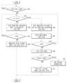
도 8은 실시 예에 따른 차량의 제어 순서도로, 도 9를 참조하여 설명한다.8 is a control flow chart of a vehicle according to an embodiment, and will be described with reference to FIG. 9 .
차량은 현재 시점이 고장 판단 시점인지를 판단(301)한다.The vehicle determines (301) whether the current time point is a failure determination time point.
고장 판단 시점인지를 판단하는 것은, 원격 제어 신호가 수신되었는지를 판단하는 것을 포함할 수 있다. 여기서 원격 제어 신호는, 원격 제어기, 사용자용 단말기 또는 서버로부터 수신된 신호로, 도어 언락 신호, 시동 온 신호를 포함 수 있다.Determining whether it is a failure determination point may include determining whether a remote control signal is received. Here, the remote control signal is a signal received from a remote controller, a user terminal, or a server, and may include a door unlock signal and an ignition on signal.
차량은 현재 시점이 고장 판단 시점이라고 판단되면 키오프 상태(즉 시동 오프 상태)인지를 판단(302)하고, 키오프 상태라고 판단되면 전력 관리 장치(200)에 웨이크업 신호를 전송함으로써 전력 관리 장치(200)의 전력 제어기(220) 및 복수 개의 마스터 제어기들이 슬립 모드에서 웨이크 업 모드로 전환되도록 할 수 있다.If it is determined that the current time point is the failure determination time point, the vehicle determines whether it is in a key-off state (ie, ignition off state) (302) and transmits a wake-up signal to the
차량은 전력 제어기를 통해 복수 개의 마스터 제어기들에 배터리의 전력을 공급하도록 한다.The vehicle supplies battery power to a plurality of master controllers through a power controller.
차량은 전력 관리 장치(200)가 웨이크업 되면 전력 제어기(220)를 이용하여 메인 시그널 라인을 통한 배터리의 전력 공급에 대한 고장을 진단(303)할 수 있고, 복수 개의 마스터 제어기들에 연결된 메인 시그널 라인을 통한 배터리의 전력 공급에 대한 고장을 진단할 수 있다.When the
좀 더 구체적으로, 차량은 전력 제어기에 마련된 제1전압 센서(221a)에 의해 검출된 제1전압 정보와 제2전압 센서(221b)에 의해 검출된 제2전압 정보를 획득하고, 획득한 제1전압 정보와 제2전압 정보에 기초하여 배터리의 전력 공급에 대한 고장 여부를 판단하고, 배터리의 전력 공급이 정상적이라고 판단되면 차량에 마련된 복수 개의 제어기에 전력 공급을 제어할 수 있다.More specifically, the vehicle acquires the first voltage information detected by the
차량은 배터리의 전력 공급에 대한 고장을 진단할 때, 제1전압 정보에 기초하여 제1메인 시그널 라인을 통해 인가되는 배터리의 제1전압이 제1기준 전압 범위 이내인지를 판단하고, 제1전압이 제1기준 전압 범위 이내라고 판단되면 제1메인 시그널 라인을 통한 배터리의 전력 공급을 정상 상태로 판단하고, 제1전압이 제1기준 전압 미만이라고 판단되면 배터리의 방전 또는 메인 시그널 라인을 통한 전력 공급을 고장 상태로 판단한다.When diagnosing a failure of the power supply of the battery, the vehicle determines whether the first voltage of the battery applied through the first main signal line is within a first reference voltage range based on the first voltage information, and determines the first voltage If it is determined that it is within the first reference voltage range, the power supply of the battery through the first main signal line is determined to be in a normal state, and if it is determined that the first voltage is less than the first reference voltage, the battery is discharged or the power through the main signal line is determined. The supply is judged to be in a faulty state.
차량은 제2전압 정보에 기초하여 제2메인 시그널 라인을 통해 인가되는 배터리의 제2전압이 제1기준 전압 범위 이내인지를 판단하고, 제2전압이 제1기준 전압 범위 이내라고 판단되면 제2메인 시그널 라인을 통한 배터리의 전력 공급을 정상 상태로 판단하고, 제2전압이 제1기준 전압 미만이라고 판단되면 배터리의 방전 또는 제2 메인 시그널 라인을 통한 전력 공급을 고장 상태로 판단한다.The vehicle determines whether the second voltage of the battery applied through the second main signal line is within the first reference voltage range based on the second voltage information, and if it is determined that the second voltage is within the first reference voltage range, the second voltage The power supply of the battery through the main signal line is determined to be in a normal state, and when the second voltage is determined to be less than the first reference voltage, the discharge of the battery or the power supply through the second main signal line is determined to be in a failure state.
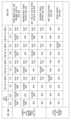
도 9에 도시된 바와 같이, 차량은 제1, 2 메인 시그널 라인을 통한 전력 공급이 모두 고장 상태라고 판단되면 배터리의 방전이나 배터리의 고장으로 판단할 수 있다.As shown in FIG. 9 , when it is determined that power supply through the first and second main signal lines is both in a failure state, the vehicle may determine that the battery is discharged or the battery is out of order.
차량은 제1 메인 시그널 라인을 통한 전력 공급이 정상이고, 제2 메인 시그널 라인을 통한 전력 공급이 고장이면, 제2 메인 시그널 라인을 통한 전력 공급을 고장으로 판단할 수 있다.When the power supply through the first main signal line is normal and the power supply through the second main signal line fails, the vehicle may determine that the power supply through the second main signal line has failed.
차량은 제1 메인 시그널 라인을 통한 전력 공급이 고장이고, 제2 메인 시그널 라인을 통한 전력 공급이 정상이면, 제1 메인 시그널 라인을 통한 전력 공급을 고장으로 판단할 수 있다.When the power supply through the first main signal line fails and the power supply through the second main signal line is normal, the vehicle may determine that the power supply through the first main signal line has failed.
차량은 복수 개의 마스터 제어기에 각각 마련된 제3전압 센서(150a)에 의해 검출된 제3전압 정보를 획득하고, 획득한 제3전압 정보에 기초하여 배터리의 전력 공급에 대한 고장 여부를 판단할 수 있다.The vehicle may obtain third voltage information detected by
차량은 배터리의 전력 공급에 대한 고장이라고 판단(304)되면 배터리의 전력 공급에 대한 고장 정보를 클러스터 및 AVN 장치 중 적어도 하나를 통해 표시(305)할 수 있다.If it is determined that the battery's power supply has failed (304), the vehicle may display (305) failure information on the battery's power supply through at least one of the cluster and the AVN device.
도 9에 도시된 바와 같이, 차량은 전력 제어기(220)의 제1전압 센서를 통해 검출된 제1전압이 제1기준 전압 미만이고, 제1마스터 제어기(151)의 제3전압 센서를 통해 검출된 전압이 제1기준 전압 미만이며, 제2마스터 제어기(152)의 제3전압 센서를 통해 검출된 전압이 제1기준 전압 미만이면, 제1메인 시그널 라인을 통한 전력 공급의 고장으로 판단하고, 제1메인 시그널 라인과 제1, 2마스터 제어기(151, 152)에 의해 제어되는 부하의 점검을 안내하는 알림 정보를 표시할 수 있다.As shown in FIG. 9 , the vehicle detects that the first voltage detected through the first voltage sensor of the
도 9에 도시된 바와 같이, 차량은 전력 제어기(220)의 제2전압 센서를 통해 검출된 제2전압이 제1기준 전압 미만이고, 제3마스터 제어기(153)의 제3전압 센서를 통해 검출된 전압이 제1기준 전압 미만이며, 제4마스터 제어기(154)의 제3전압 센서를 통해 검출된 전압이 제1기준 전압 미만이면, 제2메인 시그널 라인을 통한 전력 공급의 고장으로 판단하고, 제2메인 시그널 라인과 제3, 4마스터 제어기(153, 154)에 의해 제어되는 부하의 점검을 안내하는 알림 정보를 표시할 수 있다.As shown in FIG. 9 , the vehicle detects that the second voltage detected through the second voltage sensor of the
도 9에 도시된 바와 같이, 차량은 전력 제어기(220)의 제1전압 센서를 통해 검출된 제1전압이 제1기준 전압 범위 이내이고, 제1마스터 제어기의 제3전압 센서를 통해 검출된 전압이 제1기준 전압 범위 이내이며, 제2마스터 제어기(152)의 제3전압 센서를 통해 검출된 전압이 제1기준 전압 미만이면 제2마스터 제어기(152)에 의해 제어되는 부하의 점검을 안내하는 알림 정보를 표시할 수 있다.As shown in FIG. 9 , in the vehicle, the first voltage detected through the first voltage sensor of the
즉, 차량은 제1메인 시그널 라인에 연결된 복수 개의 마스터 제어기에서 전송된 전압이 모두 제1기준 전압 미만이면, 제1메인 시그널 라인의 고장으로 판단하고, 제2메인 시그널 라인에 연결된 복수 개의 마스터 제어기에서 전송된 전압이 모두 제1기준 전압 미만이면, 제2메인 시그널 라인의 고장으로 판단할 수 있다.That is, if the voltages transmitted from the plurality of master controllers connected to the first main signal line are all lower than the first reference voltage, the vehicle determines that the first main signal line is out of order, and the plurality of master controllers connected to the second main signal line If all of the voltages transmitted from are less than the first reference voltage, it may be determined that the second main signal line is out of order.
차량은 제1메인 시그널 라인에 연결된 복수 개의 마스터 제어기들 중 일부에서 전송된 전압이 제1기준 전압 미만이면 일부의 마스터 제어기의 고장으로 판단할 수 있다.If the voltage transmitted from some of the plurality of master controllers connected to the first main signal line is less than the first reference voltage, the vehicle may determine that some of the master controllers have failed.
차량은 키 온 상태라고 판단되면 전력 제어기와 복수 개의 마스터 제어기를 이용하여 고장을 진단(306)할 수 있다.When it is determined that the vehicle is in a key-on state, a failure can be diagnosed (306) using the power controller and a plurality of master controllers.
좀 더 구체적으로, 전력 제어기는 복수 개의 마스터 제어기에 고장 진단을 요청할 수 있다.More specifically, the power controller may request fault diagnosis to a plurality of master controllers.
이때 복수 개의 마스터 제어기는 제3전압 센서를 통해 검출된 제3전압 정보와, 제4전압 센서를 통해 검출된 제4전압 정보를 획득하고 획득한 제3전압 정보에 기초하여 메인 시그널 라인을 통한 전력 공급에 대한 고장을 진단하고, 제4전압 정보에 기초하여 전력 시그널 라인을 통한 전력 공급에 대한 고장을 진단하며 고장으로 판단되면 고장 정보를 전력 제어기에 전송할 수 있다.At this time, the plurality of master controllers obtain the third voltage information detected through the third voltage sensor and the fourth voltage information detected through the fourth voltage sensor, and power through the main signal line based on the obtained third voltage information. A failure in the supply is diagnosed, and a failure in the power supply through the power signal line is diagnosed based on the fourth voltage information, and failure information is transmitted to the power controller when it is determined to be a failure.
예를 들어, 제1마스터 제어기에 제1이그니션 시그널 라인이 연결되고, 제2마스터 제어기에 액세서리 시그널 라인이 연결되며, 제3마스터 제어기에 제3이그니션 시그널 라인에 연결되고, 제4마스터 제어기에 제2이그니션 시그널 라인에 연결된 예에 대해 설명한다.For example, the first ignition signal line is connected to the first master controller, the accessory signal line is connected to the second master controller, the third ignition signal line is connected to the third master controller, and the second ignition signal line is connected to the fourth master controller. 2 An example connected to the ignition signal line will be described.
제1마스터 제어기는 제1이그니션 시그널 라인의 전압 정보에 기초하여 제1이그니션 시그널 라인을 통해 인가되는 전력 공급의 고장 여부를 판단하고, 제2마스터 제어기는 액세서리 시그널 라인의 전압 정보에 기초하여 액세서리 시그널 라인을 통해 인가되는 전력 공급의 고장 여부를 판단하며, 제3마스터 제어기는 제3이그니션 시그널 라인의 전압 정보에 기초하여 제3이그니션 시그널 라인을 통해 인가되는 전력 공급의 고장 여부를 판단하고, 제4마스터 제어기는 제2이그니션 시그널 라인의 전압 정보에 기초하여 제2이그니션 시그널 라인을 통해 인가되는 전력 공급의 고장 여부를 판단한다.The first master controller determines whether or not the power supply applied through the first ignition signal line has failed based on the voltage information of the first ignition signal line, and the second master controller determines whether or not the power supply applied through the first ignition signal line is out of order based on the voltage information of the accessory signal line. It is determined whether the power supply applied through the line has failed, and the third master controller determines whether the power supply applied through the third ignition signal line has failed based on the voltage information of the third ignition signal line, and the fourth The master controller determines whether a power supply applied through the second ignition signal line is out of order based on voltage information of the second ignition signal line.
전력 제어기는, 복수 개의 마스터 제어기들로부터 고장 정보가 수신되면 수신된 고장 정보들을 이용하여 차량의 전력 공급에 대한 고장을 종합적으로 진단할 수 있다.When failure information is received from the plurality of master controllers, the power controller may comprehensively diagnose a failure of the power supply of the vehicle using the received failure information.
즉 차량은 전력 제어기를 이용하여 복수 개의 마스터 제어기들에서 전송된 고장 정보에 기초하여 메인 시그널 라인과 복수 개의 전력 시그널 라인에서의 고장을 종합적으로 진단(307)한다.That is, the vehicle comprehensively diagnoses (307) failures in the main signal line and the plurality of power signal lines based on failure information transmitted from the plurality of master controllers using the power controller.
도 9에 도시된 바와 같이, 차량은 제1마스터 제어기의 제1이그니션 시그널 라인의 전압이 제2기준 전압 미만이라고 판단되면 제1마스터 제어기 및 제1마스터 제어기에 의해 제어되는 부하의 고장으로 판단할 수 있다.As shown in FIG. 9 , when the vehicle determines that the voltage of the first ignition signal line of the first master controller is less than the second reference voltage, it is determined that the first master controller and the load controlled by the first master controller have failed. can
차량은 제3마스터 제어기의 제3이그니션 시그널 라인의 전압이 제2기준 전압 미만이라고 판단되면 제3마스터 제어기 및 제3마스터 제어기에 의해 제어되는 부하의 고장으로 판단할 수 있다.The vehicle may determine that the third master controller and the load controlled by the third master controller have failed when it is determined that the voltage of the third ignition signal line of the third master controller is less than the second reference voltage.
차량은 종합적으로 진단된 정보에 기초하여 고장 여부를 판단하고, 고장이 발생하였다고 판단(308)되되 복수 개의 고장 정보가 존재한다고 판단되면 위험도에 따라 복수 개의 고장 정보에 대한 우선 순위를 결정(309)하고, 결정된 우선 순위 정보에 기초하여 우선 순위가 높은 순서부터 고장 정보를 표시할 수 있다.The vehicle determines whether there is a failure based on the comprehensively diagnosed information, and determines that a failure has occurred (308). If it is determined that a plurality of failure information exists, the priority of the plurality of failure information is determined according to the degree of risk (309) And, based on the determined priority information, it is possible to display the failure information in the order of highest priority.
차량은 사용자 존재 여부에 대응하여 다른 방식으로 고장 정보를 출력할 수 있다. 즉 차량은 차량 내에 사용자가 존재한다고 판단(310)되면 클러스터 또는 AVN 장치를 이용하여 고장 정보를 표시(311)할 수 있고 차량 내에 사용자가 존재하지 않는다고 판단되면 서버 또는 사용자용 단말기에 고장 정보를 전송(312)할 수 있다.The vehicle may output failure information in a different manner in response to the presence or absence of the user. That is, when it is determined that a user exists in the vehicle (310), the vehicle may display fault information using a cluster or AVN device (311), and when it is determined that there is no user in the car, the fault information is transmitted to the server or user terminal. (312) You can.
차량은 키 온 상태에서 키 오프 상태로 변경된 시간이 일정 시간 이내라고 판단되면 사용자가 차량 내부에 존재한다고 판단할 수 있고, 안전 벨트의 착탈 검출 여부, 시트에 인가된 압력 검출 여부, 도어의 개폐 여부에 대응하여 사용자가 차량 내부에 존재하는지를 판단할 수 있다.If the vehicle determines that the time changed from the key-on state to the key-off state is within a certain period of time, it can determine that the user exists inside the vehicle, whether the seat belt is attached or detached, the pressure applied to the seat is detected, and the door is opened or closed. Correspondingly, it is possible to determine whether the user exists inside the vehicle.
한편, 개시된 실시예들은 컴퓨터에 의해 실행 가능한 명령어를 저장하는 기록매체의 형태로 구현될 수 있다. 명령어는 프로그램 코드의 형태로 저장될 수 있으며, 프로세서에 의해 실행되었을 때, 프로그램 모듈을 생성하여 개시된 실시예들의 동작을 수행할 수 있다. 기록매체는 컴퓨터로 읽을 수 있는 기록매체로 구현될 수 있다.Meanwhile, the disclosed embodiments may be implemented in the form of a recording medium storing instructions executable by a computer. Instructions may be stored in the form of program codes, and when executed by a processor, create program modules to perform operations of the disclosed embodiments. The recording medium may be implemented as a computer-readable recording medium.
컴퓨터가 읽을 수 있는 기록매체로는 컴퓨터에 의하여 해독될 수 있는 명령어가 저장된 모든 종류의 기록 매체를 포함한다. 예를 들어, ROM(Read Only Memory), RAM(Random Access Memory), 자기 테이프, 자기 디스크, 플래쉬 메모리, 광 데이터 저장장치 등이 있을 수 있다.Computer-readable recording media include all types of recording media in which instructions that can be decoded by a computer are stored. For example, there may be read only memory (ROM), random access memory (RAM), magnetic tape, magnetic disk, flash memory, optical data storage device, and the like.
이상에서와 같이 첨부된 도면을 참조하여 개시된 실시예들을 설명하였다.본 발명이 속하는 기술분야에서 통상의 지식을 가진 자는 본 발명의 기술적 사상이나 필수적인 특징을 변경하지 않고도, 개시된 실시예들과 다른 형태로 본 발명이 실시될 수 있음을 이해할 것이다. 개시된 실시예들은 예시적인 것이며, 한정적으로 해석되어서는 안 된다.As described above, the disclosed embodiments have been described with reference to the accompanying drawings. A person skilled in the art to which the present invention pertains may change the technical spirit or essential features of the present invention in a different form from the disclosed embodiments. It will be understood that the present invention can be practiced with The disclosed embodiments are illustrative and should not be construed as limiting.
1: 차량 200: 전력 관리 장치
210: 전력 분배기220: 전력 제어기
150: 마스터 제어기1: vehicle 200: power management device
210: power divider 220: power controller
150: master controller
Claims (20)
Translated fromKorean복수 개의 전력 시그널 라인들에 각각 연결된 복수 개의 마스터 제어기들과 통신을 수행하는 통신부; 및
상기 전압 센서로부터 수신된 전압 정보에 기초하여 상기 배터리의 전력 공급에 대한 고장을 판단하고, 상기 통신부를 통해 상기 복수 개의 마스터 제어기들로부터 각각 수신된 전압 정보에 기초하여 상기 복수 개의 전력 시그널 라인을 통한 전력 공급에 대한 고장을 각각 판단하는 프로세서를 포함하는 전력 관리 장치.a voltage sensor that detects a voltage applied to the main signal line connected to the battery and outputs voltage information about the detected voltage;
a communication unit that communicates with a plurality of master controllers respectively connected to a plurality of power signal lines; and
Based on the voltage information received from the voltage sensor, a failure in the power supply of the battery is determined, and based on the voltage information received from the plurality of master controllers through the communication unit, respectively, through the plurality of power signal lines. A power management device including processors that each determine a failure of a power supply.
전력 공급 상태에 대응하여 구분된 액세서리 시그널 라인, 제1이그니션 시그널 라인, 제2이그니션 시그널 라인 및 제3이그니션 시그널 라인을 포함하는 전력 관리 장치.The method of claim 1, wherein the plurality of power signal lines,
A power management device including an accessory signal line, a first ignition signal line, a second ignition signal line, and a third ignition signal line classified according to a power supply state.
상기 메인 시그널 라인을 복수 개로 분기하고, 상기 분기된 메인 시그널 라인을 상기 복수 개의 마스터 제어기에 각각 연결하는 인터페이스를 더 포함하는 전력 관리 장치.According to claim 1,
and an interface branching the main signal lines into a plurality of branches and connecting the branched main signal lines to the plurality of master controllers, respectively.
상기 통신부는, 외부 장치와 통신을 수행하고,
상기 프로세서는, 상기 배터리의 전력 공급에 대한 고장 정보 또는 상기 전력 시그널 라인을 통한 전력 공급에 대한 고장 정보를 상기 외부 장치로 전송하도록 상기 통신부를 제어하는 전력 관리 장치.According to claim 1,
The communication unit performs communication with an external device,
wherein the processor controls the communication unit to transmit failure information on power supply of the battery or failure information on power supply through the power signal line to the external device.
상기 복수 개의 전력 시그널 라인에 인가된 전압 정보에 기초하여 차량의 상태를 판단하는 전력 관리 장치.The method of claim 1, wherein the processor,
A power management device for determining a state of a vehicle based on voltage information applied to the plurality of power signal lines.
상기 전압 센서를 통해 수신된 전압 정보에 기초하여 배터리의 전압이 제1기준 전압 미만인지를 판단하고, 상기 배터리의 전압이 제1기준 전압 미만이라고 판단되면 상기 배터리의 전력 공급에 대한 고장으로 판단하는 전력 관리 장치.The method of claim 1, wherein the processor,
Based on the voltage information received through the voltage sensor, it is determined whether the voltage of the battery is less than a first reference voltage, and if it is determined that the voltage of the battery is less than a first reference voltage, it is determined that the power supply of the battery is faulty power management device.
상기 복수 개의 마스터 제어기들로부터 각각 수신된 전압 정보에 기초하여 각 전력 시그널 라인에 인가된 전압이 제2기준 전압 미만인지를 판단하고, 상기 제2기준 전압 미만인 전력 시그널 라인을 고장으로 판단하는 전력 관리 장치.The method of claim 1, wherein the processor,
Power management for determining whether a voltage applied to each power signal line is less than a second reference voltage based on voltage information received from each of the plurality of master controllers, and determining a power signal line that is less than the second reference voltage as a failure Device.
상기 고장으로 판단된 전력 시그널 라인에 연결된 마스터 제어기를 확인하고 상기 확인한 마스터 제어기의 비활성화를 제어하는 전력 관리 장치.The method of claim 7, wherein the processor,
A power management device that checks a master controller connected to the power signal line determined to be faulty and controls deactivation of the checked master controller.
상기 복수 개의 전력 시그널 라인에 각각 연결된 복수 개의 마스터 제어기를 포함하고,
상기 전력 관리 장치는,
상기 제1메인 시그널 라인에 인가되는 전압을 검출하고 검출한 전압에 대한 제1전압 정보를 출력하는 제1 전압 센서; 상기 제2메인 시그널 라인에 인가되는 전압을 검출하고 검출한 전압에 대한 제2전압 정보를 출력하는 제2 전압 센서; 상기 복수 개의 전력 시그널 라인들에 각각 연결된 복수 개의 마스터 제어기들과 통신을 수행하는 제1통신부; 및 상기 제 1, 2 전압 센서로부터 수신된 제1, 2 전압 정보에 기초하여 상기 배터리의 전력 공급에 대한 고장 또는 상기 배터리의 방전을 판단하고, 상기 제1통신부를 통해 상기 복수 개의 마스터 제어기들로부터 각각 수신된 전압 정보에 기초하여 상기 복수 개의 전력 시그널 라인을 통한 전력 공급에 대한 고장을 각각 판단하는 제1프로세서를 포함하는 차량.a power management device having first and second main signal lines connected to a battery, and a plurality of power signal lines connected to the battery and having different power supply states; and
A plurality of master controllers respectively connected to the plurality of power signal lines;
The power management device,
a first voltage sensor that detects a voltage applied to the first main signal line and outputs first voltage information for the detected voltage; a second voltage sensor that detects a voltage applied to the second main signal line and outputs second voltage information for the detected voltage; a first communication unit communicating with a plurality of master controllers respectively connected to the plurality of power signal lines; And based on the first and second voltage information received from the first and second voltage sensors, it is determined that the power supply of the battery is faulty or the battery is discharged, and the battery is discharged from the plurality of master controllers through the first communication unit. and a first processor configured to determine a failure of power supply through the plurality of power signal lines, respectively, based on received voltage information.
상기 제1 메인 시그널 라인 또는 상기 제 2 메인 시그널 라인에 연결되는 차량.10. The method of claim 9, wherein each of the plurality of master controllers,
A vehicle connected to the first main signal line or the second main signal line.
상기 연결된 메인 시그널 라인의 전압을 검출하고 검출한 전압에 대한 전압 정보를 출력하는 제3전압 센서와,
상기 복수 개의 전력 시그널 라인 중 어느 하나에 인가된 전압을 검출하고 상기 검출한 전압에 대한 전압 정보를 출력하는 제4전압 센서와,
상기 제3전압 센서에 의해 검출된 전압 정보와 상기 제4전압 센서에 의해 검출된 전압 정보에 기초하여 상기 연결된 메인 시그널 라인을 통한 전력 공급의 고장과, 상기 어느 하나의 전력 시그널 라인을 통한 전력 공급의 고장을 판단하는 제2프로세서를 포함하는 차량.11. The method of claim 10, wherein each of the plurality of master controllers,
A third voltage sensor for detecting the voltage of the connected main signal line and outputting voltage information on the detected voltage;
A fourth voltage sensor for detecting a voltage applied to any one of the plurality of power signal lines and outputting voltage information on the detected voltage;
Failure of the power supply through the connected main signal line based on the voltage information detected by the third voltage sensor and the voltage information detected by the fourth voltage sensor, and power supply through any one of the power signal lines A vehicle including a second processor that determines the failure of the vehicle.
상기 복수 개의 마스터 제어기 각각은, 제2통신부를 더 포함하고,
상기 제2프로세서는, 상기 연결된 메인 시그널 라인을 통한 전력 공급의 고장과, 상기 어느 하나의 전력 시그널 라인을 통한 전력 공급의 고장에 대한 고장 정보를 상기 전력 관리 장치에 전송하도록 상기 제2통신부를 제어하는 차량.According to claim 11,
Each of the plurality of master controllers further includes a second communication unit,
The second processor controls the second communication unit to transmit failure information on a failure of power supply through the connected main signal line and a failure of power supply through one of the power signal lines to the power management device. vehicle to do.
상기 복수 개의 마스터 제어기에 각각 마련된 상기 제4전압 센서의 전압 정보에 기초하여 차량의 상태를 판단하는 차량.The method of claim 11, wherein the first processor,
A vehicle that determines a state of the vehicle based on voltage information of the fourth voltage sensor provided in each of the plurality of master controllers.
전력 공급 상태에 대응하여 구분된 액세서리 시그널 라인, 제1이그니션 시그널 라인, 제2이그니션 시그널 라인 및 제3이그니션 시그널 라인을 포함하는 차량.The method of claim 9, wherein the plurality of power signal lines,
A vehicle including an accessory signal line, a first ignition signal line, a second ignition signal line, and a third ignition signal line classified according to a power supply state.
상기 제1통신부는, 외부 장치와 통신을 수행하고,
상기 제1프로세서는, 상기 배터리의 전력 공급에 대한 고장 정보 또는 상기 전력 시그널 라인을 통한 전력 공급에 대한 고장 정보를 상기 외부 장치로 전송하도록 상기 제1통신부를 제어하는 차량.According to claim 9,
The first communication unit performs communication with an external device,
wherein the first processor controls the first communication unit to transmit failure information on power supply of the battery or failure information on power supply through the power signal line to the external device.
상기 제1전압 센서를 통해 수신된 제1전압 정보에 기초하여 배터리의 제1전압이 제1기준 전압 미만인지를 판단하고, 상기 제2전압 센서를 통해 수신된 제2전압 정보에 기초하여 배터리의 제2전압이 상기 제1기준 전압 미만인지를 판단하고, 상기 배터리의 제1전압이 상기 제1기준 전압 미만이고 배터리의 제2전압이 상기 제1기준 전압 미만이라고 판단되면 상기 배터리의 고장 또는 상기 배터리의 방전으로 판단하는 차량.The method of claim 9, wherein the first processor,
It is determined whether the first voltage of the battery is less than a first reference voltage based on the first voltage information received through the first voltage sensor, and based on the second voltage information received through the second voltage sensor, the It is determined whether the second voltage is less than the first reference voltage, and if it is determined that the first voltage of the battery is less than the first reference voltage and the second voltage of the battery is less than the first reference voltage, the failure of the battery or the A vehicle judged by the discharge of the battery.
상기 배터리의 제1전압이 상기 제1기준 전압 범위 이내이고 상기 배터리의 제2전압이 상기 제1기준 전압 미만이라고 판단되면 상기 제2메인 시그널 라인의 고장으로 판단하고, 상기 배터리의 제1전압이 상기 제1기준 전압 미만이고 상기 배터리의 제2전압이 상기 제1기준 전압 범위 이내라고 판단되면 상기 제1메인 시그널 라인의 고장으로 판단하는 차량.The method of claim 16, wherein the first processor,
If it is determined that the first voltage of the battery is within the first reference voltage range and the second voltage of the battery is less than the first reference voltage, it is determined that the second main signal line is out of order, and the first voltage of the battery is determined to be less than the first reference voltage. If it is less than the first reference voltage and it is determined that the second voltage of the battery is within the first reference voltage range, it is determined that the first main signal line is out of order.
상기 복수 개의 마스터 제어기들로부터 전력 시그널 라인의 전압 정보를 각각 수신하고, 각각 수신된 전압 정보에 기초하여 각 전력 시그널 라인에 인가된 전압이 제2기준 전압 미만인지를 판단하고, 상기 제2기준 전압 미만인 전력 시그널 라인을 고장으로 판단하는 차량.The method of claim 16, wherein the first processor,
Receiving voltage information of power signal lines from the plurality of master controllers, determining whether a voltage applied to each power signal line is less than a second reference voltage based on the received voltage information, and determining whether the second reference voltage A vehicle that judges a power signal line that is less than
상기 고장으로 판단된 전력 시그널 라인에 연결된 마스터 제어기를 확인하고 상기 확인한 마스터 제어기의 비활성화를 제어하는 차량.The method of claim 18, wherein the first processor,
A vehicle that checks a master controller connected to the power signal line determined to be faulty and controls deactivation of the checked master controller.
클러스터 및 오디오/비디오/내비게이션 장치(AVN 장치)를 더 포함하고,
상기 제1프로세서는, 상기 배터리의 전력 공급에 대한 고장 정보 또는 상기 전력 시그널 라인을 통한 전력 공급에 대한 고장 정보를 표시하도록 상기 클러스터 및 오디오/비디오/내비게이션 장치 중 적어도 하나를 제어하는 차량.
According to claim 9,
Further comprising a cluster and an audio/video/navigation device (AVN device);
wherein the first processor controls at least one of the cluster and audio/video/navigation device to display failure information on power supply of the battery or failure information on power supply through the power signal line.
Priority Applications (3)
| Application Number | Priority Date | Filing Date | Title |
|---|---|---|---|
| KR1020210185707AKR20230096328A (en) | 2021-12-23 | 2021-12-23 | Power management device and vehicle having the same |
| US17/968,632US12099393B2 (en) | 2021-12-23 | 2022-10-18 | Power management apparatus and vehicle having the same |
| CN202211403516.1ACN116330977A (en) | 2021-12-23 | 2022-11-10 | Power management device and vehicle including power management device |
Applications Claiming Priority (1)
| Application Number | Priority Date | Filing Date | Title |
|---|---|---|---|
| KR1020210185707AKR20230096328A (en) | 2021-12-23 | 2021-12-23 | Power management device and vehicle having the same |
Publications (1)
| Publication Number | Publication Date |
|---|---|
| KR20230096328Atrue KR20230096328A (en) | 2023-06-30 |
Family
ID=86877910
Family Applications (1)
| Application Number | Title | Priority Date | Filing Date |
|---|---|---|---|
| KR1020210185707APendingKR20230096328A (en) | 2021-12-23 | 2021-12-23 | Power management device and vehicle having the same |
Country Status (3)
| Country | Link |
|---|---|
| US (1) | US12099393B2 (en) |
| KR (1) | KR20230096328A (en) |
| CN (1) | CN116330977A (en) |
Families Citing this family (4)
| Publication number | Priority date | Publication date | Assignee | Title |
|---|---|---|---|---|
| US5567654A (en) | 1994-09-28 | 1996-10-22 | International Business Machines Corporation | Method and workpiece for connecting a thin layer to a monolithic electronic module's surface and associated module packaging |
| US20230390565A1 (en)* | 2022-06-02 | 2023-12-07 | West Affum Holdings Corp. | Wms-wcd having ui with voice prompt to renew battery |
| JP7729302B2 (en)* | 2022-10-07 | 2025-08-26 | トヨタ自動車株式会社 | Vehicle monitoring device |
| US20240421594A1 (en)* | 2023-06-16 | 2024-12-19 | Schneider Electric USA, Inc. | Dc fault managed power system |
Family Cites Families (6)
| Publication number | Priority date | Publication date | Assignee | Title |
|---|---|---|---|---|
| JP2013092397A (en)* | 2011-10-24 | 2013-05-16 | Denso Corp | Battery monitoring device |
| CN105378587B (en)* | 2013-06-04 | 2019-12-17 | Trw汽车美国有限责任公司 | Optimized power supply architecture |
| KR102403353B1 (en) | 2017-09-22 | 2022-06-02 | 현대자동차주식회사 | Vehicle and power control apparatus |
| KR102528233B1 (en)* | 2018-08-07 | 2023-05-03 | 현대자동차주식회사 | Vehicle, controlling method thereof and electric power management apparutus |
| KR20220091075A (en)* | 2020-12-23 | 2022-06-30 | 현대자동차주식회사 | Vehicle and method for controlling thereof |
| EP4106127B1 (en)* | 2021-06-14 | 2024-05-15 | Aptiv Technologies AG | Electrical architecture |
- 2021
- 2021-12-23KRKR1020210185707Apatent/KR20230096328A/enactivePending
- 2022
- 2022-10-18USUS17/968,632patent/US12099393B2/enactiveActive
- 2022-11-10CNCN202211403516.1Apatent/CN116330977A/enactivePending
Also Published As
| Publication number | Publication date |
|---|---|
| US12099393B2 (en) | 2024-09-24 |
| CN116330977A (en) | 2023-06-27 |
| US20230205294A1 (en) | 2023-06-29 |
Similar Documents
| Publication | Publication Date | Title |
|---|---|---|
| KR20230096328A (en) | Power management device and vehicle having the same | |
| CN109747619B (en) | Vehicle and control method for the same | |
| US10737687B2 (en) | Vehicle and method for controlling the same | |
| US8531053B2 (en) | Variable voltage control system and method for hybrid vehicle | |
| KR100829307B1 (en) | How to control fault diagnosis of high voltage relay in hybrid electric vehicle | |
| KR101394751B1 (en) | Method for detecting fuse disconnection of dc-dc converter | |
| JP5650585B2 (en) | Automotive electrical systems, automotive, automotive electrical switching devices for automotive electrical systems | |
| US10639998B2 (en) | Service disconnect notification strategy | |
| US11391257B2 (en) | Power supply during vehicle startup | |
| KR102370145B1 (en) | Battery Management apparatus, Vehicle and method for controlling the same | |
| US11584318B2 (en) | Automatic powertrain operation for maintenance of neutral operation | |
| KR20190083395A (en) | Vehicle and method for controlling thereof | |
| CN116096601B (en) | For vehicles with guaranteed safety due to risk of loss of service battery | |
| CN104340081A (en) | System and method for controlling low-voltage dc/dc converter (ldc) of hybrid electric vehicle | |
| US20190366956A1 (en) | Vehicle power and control method thereof | |
| KR20190067304A (en) | Apparatus for controlling battery charge state of vehicle and method thereof | |
| KR102586447B1 (en) | Controller of displaying charging state | |
| US20230339344A1 (en) | Power management device and vehicle having the same | |
| CN103358914B (en) | Direct current transducer for vehicle is diagnosed | |
| KR20120012662A (en) | Electric Vehicles and Emergency Control Methods | |
| US20230398899A1 (en) | Power control device and vehicle having the same | |
| KR101656809B1 (en) | User interface device, Vehicle having the same and method for controlling the same | |
| US20240123830A1 (en) | Vehicle and method of controlling the same | |
| US20230373344A1 (en) | Power Control Device and Vehicle Having the Same | |
| KR102556614B1 (en) | Vehicle and controlling method for the same |
Legal Events
| Date | Code | Title | Description |
|---|---|---|---|
| PA0109 | Patent application | St.27 status event code:A-0-1-A10-A12-nap-PA0109 | |
| PG1501 | Laying open of application | St.27 status event code:A-1-1-Q10-Q12-nap-PG1501 | |
| A201 | Request for examination | ||
| PA0201 | Request for examination | St.27 status event code:A-1-2-D10-D11-exm-PA0201 | |
| PE0902 | Notice of grounds for rejection | St.27 status event code:A-1-2-D10-D21-exm-PE0902 |