KR20230096077A - Working Shaft Retaining Mechanism for Surgical Stapler - Google Patents
Working Shaft Retaining Mechanism for Surgical StaplerDownload PDFInfo
- Publication number
- KR20230096077A KR20230096077AKR1020237018053AKR20237018053AKR20230096077AKR 20230096077 AKR20230096077 AKR 20230096077AKR 1020237018053 AKR1020237018053 AKR 1020237018053AKR 20237018053 AKR20237018053 AKR 20237018053AKR 20230096077 AKR20230096077 AKR 20230096077A
- Authority
- KR
- South Korea
- Prior art keywords
- shaft
- actuation
- handle
- rack
- actuation shaft
- Prior art date
- Legal status (The legal status is an assumption and is not a legal conclusion. Google has not performed a legal analysis and makes no representation as to the accuracy of the status listed.)
- Pending
Links
Images


Classifications
- A—HUMAN NECESSITIES
- A61—MEDICAL OR VETERINARY SCIENCE; HYGIENE
- A61B—DIAGNOSIS; SURGERY; IDENTIFICATION
- A61B17/00—Surgical instruments, devices or methods
- A61B17/068—Surgical staplers, e.g. containing multiple staples or clamps
- A61B17/072—Surgical staplers, e.g. containing multiple staples or clamps for applying a row of staples in a single action, e.g. the staples being applied simultaneously
- A61B17/07207—Surgical staplers, e.g. containing multiple staples or clamps for applying a row of staples in a single action, e.g. the staples being applied simultaneously the staples being applied sequentially
- A—HUMAN NECESSITIES
- A61—MEDICAL OR VETERINARY SCIENCE; HYGIENE
- A61B—DIAGNOSIS; SURGERY; IDENTIFICATION
- A61B17/00—Surgical instruments, devices or methods
- A61B2017/00367—Details of actuation of instruments, e.g. relations between pushing buttons, or the like, and activation of the tool, working tip, or the like
- A61B2017/00398—Details of actuation of instruments, e.g. relations between pushing buttons, or the like, and activation of the tool, working tip, or the like using powered actuators, e.g. stepper motors, solenoids
- A—HUMAN NECESSITIES
- A61—MEDICAL OR VETERINARY SCIENCE; HYGIENE
- A61B—DIAGNOSIS; SURGERY; IDENTIFICATION
- A61B17/00—Surgical instruments, devices or methods
- A61B2017/0046—Surgical instruments, devices or methods with a releasable handle; with handle and operating part separable
Landscapes
- Health & Medical Sciences (AREA)
- Life Sciences & Earth Sciences (AREA)
- Surgery (AREA)
- Heart & Thoracic Surgery (AREA)
- Engineering & Computer Science (AREA)
- Biomedical Technology (AREA)
- Nuclear Medicine, Radiotherapy & Molecular Imaging (AREA)
- Medical Informatics (AREA)
- Molecular Biology (AREA)
- Animal Behavior & Ethology (AREA)
- General Health & Medical Sciences (AREA)
- Public Health (AREA)
- Veterinary Medicine (AREA)
- Surgical Instruments (AREA)
- Orthopedics, Nursing, And Contraception (AREA)
Abstract
Translated fromKoreanDescription
Translated fromKorean관련 출원들에 대한 상호 참조CROSS REFERENCES TO RELATED APPLICATIONS
본 출원은 "Actuation Shaft Retention Mechanism for Surgical Stapler"라는 명칭으로 2020년 10월 29일자로 출원된 미국 가특허 출원 일련 번호 제63/107,112호의 이익 및 이에 대한 우선권을 주장하며, 이는 그 전체가 본원에 참조로서 포함된다.This application claims the benefit of and priority to U.S. Provisional Patent Application Serial No. 63/107,112, filed on October 29, 2020, entitled "Actuation Shaft Retention Mechanism for Surgical Stapler," which is incorporated herein in its entirety. included as a reference.
기술분야technology field
본 출원은 전반적으로 수술용 폐색 기구들에 관한 것으로서, 더 구체적으로는, 수술용 스테이플러들에 관한 것이다.[0002] This application relates generally to surgical occlusive instruments, and more particularly to surgical staplers.
수술용 스테이플러들은 조직을 클램핑(clamp)하거나 또는 접근시키기 위하여 그리고 클램핑된 조직을 함께 스테이플하기 위하여 사용된다. 이와 같이, 수술용 스테이플러들은 조직을 클램핑하기 위한 그리고 조직을 관통해 스테이플(staple)들을 드라이브(drive)하기 위한 메커니즘들을 갖는다. 결과적으로, 이는, 예를 들어, 클램핑된 조직의 적절한 스테이플링을 제공하기 위한 복잡한 메커니즘들과 함께 복수의 트리거(trigger)들 및 핸들들을 초래하였다. 이러한 복잡한 메커니즘들을 이용하면, 수술용 스테이플러들은 디바이스 고장 및 사용자에 대한 혼란에 대한 잠재적인 소스들뿐만 아니라 증가된 제조 부담을 가질 수 있다. 따라서, 복잡한 메커니즘들 없이 클램핑된 조직의 신뢰할 수 있는 스테이플링이 희망된다.Surgical staplers are used to clamp or access tissue and to staple the clamped tissue together. As such, surgical staplers have mechanisms for clamping tissue and for driving staples through tissue. Consequently, this has resulted in multiple triggers and handles, for example, along with complex mechanisms to provide proper stapling of clamped tissue. Using these complex mechanisms, surgical staplers can have an increased manufacturing burden as well as potential sources of device failure and confusion to the user. Therefore, reliable stapling of clamped tissue without complicated mechanisms is desired.
조 어셈블리들을 클램핑하고 조 어셈블리로부터 스테이플들을 발사하기 위한 전기 구동 모터(electrically powered motor)들을 갖는 수술용 스테이플러들은, 조직을 통한 스테이플들의 적용을 위한 사용자의 노력을 감소시키고, 절차 동안 다수의 스테이플 라인들이 위치될 때 작업부하를 감소시킴으로써 스테이플링을 용이하게 할 수 있다. 전기 구동 스테이플러가, 사용자가 스테이플러를 특정 경우들에 초기 구성으로 수동으로 복귀시키는 것을 가능하게 하기 위한 수동 복귀 메커니즘을 갖는 것이 바람직할 수 있다.Surgical staplers with electrically powered motors for clamping jaw assemblies and ejecting staples from jaw assemblies reduce user effort for application of staples through tissue, and multiple staple lines during the procedure Stapling can be facilitated by reducing the workload when positioned. It may be desirable for an electrically driven stapler to have a manual return mechanism to enable a user to manually return the stapler to its initial configuration in certain instances.
특정 실시예들에서, 수술용 스테이플러에 대한 핸들 어셈블리가 제공된다. 핸들 어셈블리는 핸들 몸체, 전기 모터, 작동 샤프트, 기계적 복귀 메커니즘, 및 유지 메커니즘을 포함한다. 핸들 몸체는 고정식 핸들 및 핸들 몸체에 피봇가능하게 결합된 트리거를 포함한다. 전기 모터는 핸들 몸체 내에 배치된다. 작동 샤프트는 길이 방향 축을 따라 핸들 몸체 내에서 슬라이드할 수 있으며, 길이 방향 축에 대하여 핸들 몸체 내에서 회전할 수 있다. 작동 샤프트는 그 위에 형성된 랙(rack)을 포함한다. 유지 메커니즘은, 기계적 복귀 메커니즘의 작동 시에 작동 샤프트의 원위 길이 방향 전진을 제한하도록 구성된다.In certain embodiments, a handle assembly for a surgical stapler is provided. The handle assembly includes a handle body, an electric motor, an actuation shaft, a mechanical return mechanism, and a retention mechanism. The handle body includes a stationary handle and a trigger pivotally coupled to the handle body. An electric motor is disposed within the handle body. The actuating shaft can slide within the handle body along a longitudinal axis and can rotate within the handle body about the longitudinal axis. The working shaft includes a rack formed thereon. The retention mechanism is configured to limit distal longitudinal advancement of the actuation shaft upon actuation of the mechanical return mechanism.
특정 실시예들에서, 수술용 스테이플러에 대한 핸들 어셈블리가 제공된다. 핸들 어셈블리는 핸들 몸체, 전기 모터, 작동 샤프트, 기계적 복귀 메커니즘, 및 작동 샤프트와 맞물릴 수 있는 복수의 핀(fin)들을 포함한다. 핸들 몸체는 고정식 핸들 및 핸들 몸체에 피봇가능하게 결합된 트리거를 포함한다. 전기 모터는 핸들 몸체 내에 배치된다. 작동 샤프트는 길이 방향 축을 따라 핸들 몸체 내에서 슬라이드할 수 있으며, 길이 방향 축에 대하여 핸들 몸체 내에서 회전할 수 있다. 작동 샤프트는 그 위에 형성된 랙을 포함한다. 복수의 핀들은 기계적 복귀 메커니즘의 작동 시에 작동 샤프트와 맞물릴 수 있다. 복수의 핀들은, 근위 방향으로의 작동 샤프트의 움직임을 허용하고 샤프트가 원위 방향으로 움직이는 것을 제한하기 위해 길이 방향 축에 대해 횡방향으로 연장된다.In certain embodiments, a handle assembly for a surgical stapler is provided. The handle assembly includes a handle body, an electric motor, an actuation shaft, a mechanical return mechanism, and a plurality of fins engageable with the actuation shaft. The handle body includes a stationary handle and a trigger pivotally coupled to the handle body. An electric motor is disposed within the handle body. The actuating shaft can slide within the handle body along a longitudinal axis and can rotate within the handle body about the longitudinal axis. The working shaft includes a rack formed thereon. A plurality of pins may engage the actuating shaft upon actuation of the mechanical return mechanism. A plurality of pins extend transversely to the longitudinal axis to allow movement of the actuation shaft in a proximal direction and to limit movement of the shaft in a distal direction.
특정 실시예들에서, 수술용 스테이플러에 대한 핸들 어셈블리가 제공된다. 핸들 어셈블리는 핸들 몸체, 전기 모터, 작동 샤프트, 기계적 복귀 메커니즘, 및 유지 메커니즘을 포함한다. 핸들 몸체는 고정식 핸들 및 핸들 몸체에 피봇가능하게 결합된 트리거를 포함한다. 전기 모터는 핸들 몸체 내에 배치된다. 작동 샤프트는 길이 방향 축을 따라 핸들 몸체 내에서 슬라이드할 수 있으며, 길이 방향 축에 대하여 핸들 몸체 내에서 회전할 수 있다. 작동 샤프트는 그 위에 형성된 랙을 포함한다. 기계적 복귀 메커니즘은 샤프트 회전 메커니즘 및 샤프트 후퇴(retraction) 메커니즘을 포함한다. 유지 메커니즘은, 샤프트 후퇴 메커니즘의 작동 시에 작동 샤프트의 원위 길이 방향 전진을 방지하도록 구성된다. 작동 샤프트는, 작동 샤프트를 길이 방향으로 슬라이드시키기 위하여 랙이 전기 모터와 동작가능하게 맞물리는 제1 위치로부터 랙이 전기 모터로부터 분리되고 수동 복귀 메커니즘과 맞물리고 유지 메커니즘과 맞물리는 제2 위치로 회전가능하다.In certain embodiments, a handle assembly for a surgical stapler is provided. The handle assembly includes a handle body, an electric motor, an actuation shaft, a mechanical return mechanism, and a retention mechanism. The handle body includes a stationary handle and a trigger pivotally coupled to the handle body. An electric motor is disposed within the handle body. The actuating shaft can slide within the handle body along a longitudinal axis and can rotate within the handle body about the longitudinal axis. The working shaft includes a rack formed thereon. The mechanical return mechanism includes a shaft rotation mechanism and a shaft retraction mechanism. The retention mechanism is configured to prevent distal longitudinal advancement of the actuation shaft upon actuation of the shaft retraction mechanism. The actuation shaft rotates from a first position where the rack is operatively engaged with the electric motor to a second position where the rack is disengaged from the electric motor, engages a manual return mechanism, and engages a retaining mechanism to longitudinally slide the actuation shaft. possible.
도 1은 전동 핸들의 일 실시예를 갖는 수술용 스테이플링 시스템의 일 실시예의 사시도이다.
도 2는 도 1의 수술용 스테이플링 시스템의 전동 핸들의 측면도이다.
도 3은 이것의 드라이브 시스템을 예시하기 위하여 구성요소들이 제거된 상태의 도 2의 전동 핸들의 부분 절개 사시도이다.
도 4는, 오버라이드(override) 복귀 메커니즘이 분리된(disengaged) 구성에 있는 상태의 도 2의 전동 핸들의 사시도이다.
도 5는, 오버라이드 복귀 메커니즘이 복귀 구성으로의 움직임을 위하여 잠금 해제된 상태의 도 2의 전동 핸들의 사시도이다.
도 6은, 오버라이드 복귀 메커니즘이 복귀 구성으로의 움직임을 위해 잠금 해제된 상태의 도 2의 전동 핸들의 부분 절개 사시도이다.
도 7은, 오버라이드 복귀 메커니즘이 분리된 구성에 있는 상태의 도 2의 전동 핸들의 부분 절개 측면도이다.
도 8은, 오버라이드 복귀 메커니즘이 복귀 구성으로의 움직임을 위하여 잠금 해제된 상태의 도 2의 전동 핸들의 부분 절개 측면도이다.
도 9는, 오버라이드 복귀 메커니즘이 복귀 구성에 있는 상태의 도 2의 전동 핸들의 사시도이다.
도 10은, 오버라이드 복귀 메커니즘이 복귀 구성에 있는 상태의 도 2의 전동 핸들의 부분 절개 사시도이다.
도 11은, 오버라이드 복귀 메커니즘이 복귀 구성에 있으며 수동 복귀 사이클이 개시된 상태의 도 2의 전동 핸들의 부분 절개 사시도이다.
도 12a는 도 2의 전동 핸들의 오버라이드 복귀 메커니즘의 복귀 폴(pawl)의 사시도이다.
도 12b는 도 2의 전동 핸들의 오버라이드 복귀 메커니즘의 측면도이다.
도 12c는 도 2의 전동 핸들의 오버라이드 복귀 메커니즘의 측면도이다.
도 13은, 작동 샤프트가 작동 메커니즘으로부터 제거된 상태의 도 2의 전동 핸들의 부분 절개 사시도이다.
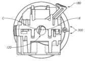
도 14는 작동 샤프트 유지 메커니즘의 일 실시예를 갖는 도 2의 전동 핸들의 부분 절개 사시도이다.
도 15는 도 14의 작동 메커니즘의 상세도이다.
도 16은 도 14의 유지 메커니즘의 상세도이다.
도 17은 도 14의 유지 메커니즘의 상세도이다.
도 18은, 오버라이드 복귀 메커니즘이 분리된 구성에 있는 상태의 도 14의 작동 샤프트 및 유지 메커니즘의 단부 단면도이다.
도 19는, 오버라이드 복귀 메커니즘이 복귀 구성에 있는 상태의 도 14의 작동 샤프트 및 유지 메커니즘의 단부 단면도이다.
도 20은 유지 메커니즘의 다른 실시예를 갖는 전동 핸들 어셈블리의 절개 측면도이다.
도 21은 작동 샤프트의 일 실시예 상에 배치된 유지 메커니즘의 다른 실시예의 사시도이다.
도 22는 도 21의 유지 메커니즘의 사시도이다.
도 23은 작동 샤프트의 일 실시예 상에 배치된 유지 메커니즘의 다른 실시예의 사시도이다.
도 24는 전동 핸들의 작동 메커니즘의 일 실시예에서 도 23의 유지 메커니즘의 절개 사시도이다.
도 25는 분리된 구성의 오버라이드 복귀 메커니즘의 일 실시예의 측면도이다.
도 26은 복귀 구성의 도 25의 오버라이드 복귀 메커니즘의 측면도이다.
도 27은, 도 25의 오버라이드 복귀 메커니즘 상에 위치된 유지 메커니즘의 다른 실시예의 상세 사시도이다.
도 28은 유지 메커니즘의 다른 실시예를 갖는 오버라이드 복귀 메커니즘의 일 실시예의 절개 사시도이다.
도 29는 도 28의 유지 메커니즘의 사시도이다.
도 30은, 전동 핸들의 전동 동작을 위해 배향된 작동 샤프트를 갖는 유지 메커니즘의 다른 실시예를 갖는 전동 핸들의 작동 메커니즘의 일 실시예의 절개 측면도이다.
도 31은, 수동 복귀 메커니즘을 이용한 동작을 위해 배향된 작동 샤프트를 갖는 도 30의 작동 메커니즘의 절개 측면도이다.
도 32는 작동 샤프트의 길이 방향 움직임을 유지하는 유지 메커니즘을 갖는 도 30의 작동 메커니즘의 절개 측면도이다.
도 33은, 분리된 구성의 오버라이드 복귀 메커니즘을 갖는 전동 핸들의 작동 메커니즘의 일 실시예의 단부 단면도이다.
도 34는 복귀 구성의 오버라이드 복귀 메커니즘을 갖는 도 32의 작동 메커니즘의 단부 단면도이다.
도 35는 복귀 구성의 도 32의 오버라이드 복귀 메커니즘의 상세도이다.
도 36은, 분리된 구성의 전동 핸들의 작동 메커니즘의 일 실시예의 단부 단면도이다.
도 37은, 복귀 구성의 전동 핸들의 작동 메커니즘의 일 실시예의 단부 단면도이다.
도 38은 도 35의 작동 메커니즘에 대한 유지 메커니즘의 일 실시예의 상세 사시도이다.
도 39는 도 35의 작동 메커니즘에 대한 유지 메커니즘의 다른 실시예의 상세 사시도이다.
도 40은 도 35의 작동 메커니즘에 대한 유지 메커니즘의 다른 실시예의 상세 사시도이다.
도 41은, 분리된 구성의 오버라이드 복귀 메커니즘을 갖는 전동 핸들의 작동 메커니즘에 대한 유지 메커니즘의 다른 실시예의 상세 측면도이다.
도 42는, 복귀 구성의 오버라이드 복귀 메커니즘을 갖는 도 40의 유지 메커니즘의 상세 측면도이다.
도 43은, 작동 샤프트와 맞물리는 유지 메커니즘을 갖는 도 40의 유지 메커니즘의 상세 측면도이다.1 is a perspective view of one embodiment of a surgical stapling system having one embodiment of a powered handle.
Fig. 2 is a side view of the powered handle of the surgical stapling system of Fig. 1;
FIG. 3 is a partially cut-away perspective view of the powered handle of FIG. 2 with components removed to illustrate its drive system.
Figure 4 is a perspective view of the drive handle of Figure 2 with the override return mechanism in a disengaged configuration;
Figure 5 is a perspective view of the drive handle of Figure 2 with the override return mechanism unlocked for movement into a return configuration;
Fig. 6 is a perspective cut-away view of the drive handle of Fig. 2 with the override return mechanism unlocked for movement into the retract configuration;
Fig. 7 is a partially cut-away side view of the power handle of Fig. 2 with the override return mechanism in a disengaged configuration;
Figure 8 is a partially cut-away side view of the drive handle of Figure 2 with the override return mechanism unlocked for movement into a return configuration;
Fig. 9 is a perspective view of the powered handle of Fig. 2 with the override return mechanism in a retracted configuration;
Fig. 10 is a partially cut-away perspective view of the power handle of Fig. 2 with the override return mechanism in a retracted configuration;
Fig. 11 is a partially cut-away perspective view of the drive handle of Fig. 2 with the override return mechanism in a retracted configuration and a manual retract cycle initiated;
Fig. 12a is a perspective view of a return pawl of the override return mechanism of the powered handle of Fig. 2;
Fig. 12b is a side view of the override return mechanism of the powered steering wheel of Fig. 2;
Fig. 12c is a side view of the override return mechanism of the powered steering wheel of Fig. 2;
Fig. 13 is a partially cut-away perspective view of the power handle of Fig. 2 with the actuation shaft removed from the actuation mechanism;
Fig. 14 is a partially cut-away perspective view of the power handle of Fig. 2 with one embodiment of an actuating shaft retaining mechanism;
Fig. 15 is a detailed view of the actuation mechanism of Fig. 14;
Fig. 16 is a detailed view of the retaining mechanism of Fig. 14;
Fig. 17 is a detailed view of the retaining mechanism of Fig. 14;
18 is an end cross-sectional view of the actuation shaft and retention mechanism of FIG. 14 with the override return mechanism in a disengaged configuration.
19 is an end cross-sectional view of the actuation shaft and retention mechanism of FIG. 14 with the override return mechanism in a return configuration.
20 is a cut-away side view of a powered handle assembly with another embodiment of a retaining mechanism.
21 is a perspective view of another embodiment of a retaining mechanism disposed on one embodiment of an actuating shaft;
Fig. 22 is a perspective view of the retaining mechanism of Fig. 21;
23 is a perspective view of another embodiment of a retaining mechanism disposed on one embodiment of an actuating shaft;
Fig. 24 is a cut-away perspective view of the holding mechanism of Fig. 23 in one embodiment of the actuation mechanism of the powered handle;
25 is a side view of one embodiment of an override return mechanism in a decoupled configuration.
Fig. 26 is a side view of the override return mechanism of Fig. 25 in a return configuration;
Fig. 27 is a detailed perspective view of another embodiment of a retaining mechanism positioned on the override return mechanism of Fig. 25;
28 is a cut-away perspective view of one embodiment of an override return mechanism with another embodiment of a retaining mechanism;
Fig. 29 is a perspective view of the retaining mechanism of Fig. 28;
30 is a cut-away side view of one embodiment of an actuating mechanism for a powered handle with another embodiment of the holding mechanism having an actuating shaft oriented for powered operation of the powered handle.
Fig. 31 is a cut-away side view of the actuation mechanism of Fig. 30 with the actuation shaft oriented for operation with a manual return mechanism;
Fig. 32 is a cut-away side view of the actuation mechanism of Fig. 30 having a retaining mechanism for maintaining longitudinal movement of the actuation shaft;
33 is an end cross-sectional view of one embodiment of an operating mechanism for a powered steering wheel having an override return mechanism in a separate configuration.
34 is an end cross-sectional view of the actuation mechanism of FIG. 32 with an override return mechanism in a return configuration;
35 is a detailed view of the override return mechanism of FIG. 32 in a return configuration;
36 is an end cross-sectional view of one embodiment of an operating mechanism for a powered handle in a decoupled configuration.
37 is an end cross-sectional view of one embodiment of an operating mechanism of a powered handle in a return configuration.
38 is a detailed perspective view of one embodiment of a retention mechanism for the actuation mechanism of FIG. 35;
39 is a detailed perspective view of another embodiment of a retaining mechanism for the actuation mechanism of FIG. 35;
40 is a detailed perspective view of another embodiment of a retaining mechanism for the actuation mechanism of FIG. 35;
41 is a detailed side view of another embodiment of a retaining mechanism for an operating mechanism of a powered steering wheel having an override return mechanism in a separate configuration;
Fig. 42 is a detailed side view of the retention mechanism of Fig. 40 having an override return mechanism in a return configuration;
Fig. 43 is a detailed side view of the retaining mechanism of Fig. 40 having the retaining mechanism engaged with the actuating shaft;
도 1 내지 도 2를 참조하면, 수술용 스테이플링 시스템의 일 실시예가 예시된다. 수술용 스테이플러(10)의 예시된 실시예는 세장형 샤프트(20), 조(jaw) 어셈블리(30), 및 핸들 어셈블리(40)를 포함한다. 도 1은, 전동 핸들의 일 실시예가 전동 스테이플 발사 및 수동 조 어셈블리 관절(articulation)을 갖는 상태의 개방 구성의 조 어셈블리(30)를 갖는 수술용 스테이플러(10)를 예시한다. 도 2는 세장형 샤프트가 제거된 상태의 수술용 스테이플러 시스템(10)의 전동 핸들(40)을 예시한다. 도 2의 전동 핸들(40)은 전동 스테이플 발사 및 수동 조 어셈블리 관절을 갖는다. 예시된 실시예들에서, 샤프트(20) 및 조 어셈블리(30)는 핸들(40) 상의 회전 손잡이(knob)의 회전에 의해서 샤프트(20)에 의해 획정(define)된 길이 방향 축에 대해 자유롭게 회전될 수 있다. 다른 실시예들에서, 스테이플링 시스템은 미리 정의된 범위 또는 회전적으로 고정된 조 어셈블리 내에서 길이 방향 축에 대한 조 어셈블리의 회전을 허용하도록 구성될 수 있다.Referring to Figures 1-2, one embodiment of a surgical stapling system is illustrated. The illustrated embodiment of a surgical stapler (10) includes an elongate shaft (20), a jaw assembly (30), and a handle assembly (40). 1 illustrates a
계속해서 도 1을 참조하면, 수술용 스테이플러(10)의 예시된 실시예는 복강경 수술 절차들에서 사용하기 위해 크기가 결정되고 구성될 수 있다. 예를 들어, 세장형 샤프트(20) 및 조 어셈블리(30)는 액세스 포트 또는 투관침 캐뉼라(trocar cannula)를 통해 수술 필드 내로 도입될 수 있도록 크기가 결정되고 구성될 수 있다. 일부 실시예들에서, 세장형 샤프트(20) 및 조 어셈블리(30)는, 상대적으로 작은 작업 채널 직경, 예를 들어, 8 mm 미만의 직경을 갖는 투관침 캐뉼라를 통해 삽입되도록 크기가 결정되고 구성될 수 있다. 다른 실시예들에서, 세장형 샤프트(20) 및 조 어셈블리(30)는 더 큰 작업 채널 직경, 예를 들어, 10 mm, 11 mm, 12 mm, 또는 15 mm와 같은 직경을 갖는 투관침 캐뉼라를 통해 삽입되도록 크기가 결정되고 구성될 수 있다. 다른 실시예들에서, 본원에서 설명되는 수술용 스테이플러들의 특정 측면들이 개복 수술 절차들에서 사용하기 위한 수술용 스테이플링 디바이스 내에 통합될 수 있다는 것이 고려된다.With continued reference to FIG. 1 , the illustrated embodiment of a
계속해서 도 1을 참조하면, 예시된 바와 같이, 세장형 샤프트(20)는 전반적으로 튜브형 부재를 포함한다. 세장형 샤프트(20)는 근위 단부로부터 원위 단부로 연장된다. 세장형 샤프트(20)는, 근위 단부(22)와 원위 단부(24) 사이에서 연장되는 수술용 스테이플러(10)의 중심 길이 방향 축(L)을 획정한다.With continued reference to FIG. 1 , as illustrated, the
계속해서 도 1을 참조하면, 예시된 실시예에서, 조 어셈블리(30)는 세장형 샤프트(20)의 원위 단부에서 세장형 샤프트(20)에 결합된다. 조 어셈블리(30)는 제1 조(32) 및 제1 조(32)에 피봇가능하게 결합된 제2 조(34)를 포함한다. 예시된 실시예에 있어, 제1 조가 중심 길이 방향 축(L)을 따라 원위로 연장되고 그리고 핸들(40) 내의 관절 메커니즘에 응답하여 세장형 샤프트(20)에 대해 관절화될 수 있도록, 제1 조(32)는 세장형 샤프트(20)의 원위 단부(24)에 고정된다. 초기 구성에서, 제1 조(32)는 재장전물(reload)(50) 내부에 배치된 복수의 스테이플들(36)을 포함한다. 다른 실시예들에서, 재장전물(50)은, 장전된 스테이플들을 갖는 전체 샤프트 어셈블리(20) 및 조 어셈블리(30)가 단일 재장전물 어셈블리를 획정하도록 조 어셈블리(30)와 통합될 수 있다. 일부 실시예들에서, 스테이플들은 초기에 제2 조(34) 내에 위치될 수도 있다.With continued reference to FIG. 1 , in the illustrated embodiment, the
계속해서 도 1을 참조하면, 예시된 실시예에서, 조 어셈블리(30)는 세장형 샤프트 내에서 길이 방향으로 슬라이드할 수 있는 드라이브 부재 또는 빔에 의해 개방 구성(도 1)으로부터 폐쇄 구성으로 그리고 스테이플링 구성으로 작동될 수 있다. 초기 위치에서, 빔은 세장형 샤프트(20)의 원위 단부(24)에 위치될 수 있다. 빔이 초기 위치에 있는 상태에서, 제2 조(34)는 조 어셈블리(30)가 개방 구성이 되도록 제1 조(32)로부터 멀어지도록 피봇된다. 길이 방향 축(L)을 따른 원위로의 작동 부재 또는 빔의 병진 이동시에 작동 빔이 제2 조(34)와 맞물린다. 작동 빔이 초기 위치로부터 원위로 제1 거리를 병진 이동하는 것이 조 어셈블리를 개방 구성으로부터 폐쇄 구성으로 작동시킬 수 있다. 조 어셈블리(30)가 폐쇄 구성에 있는 상태에서, 작동 빔이 조 어셈블리(30)를 개방 구성으로 복귀시키기 위해 제1 거리만큼 근위로 복귀될 수 있다. 작동 빔의 원위 단부가 제1 조(32)로부터 스테이플들을 전개(deploy)하도록 구성된 스테이플 슬라이더를 전진시킬 수 있으며, 그 결과 제1 거리를 넘는 원위로의 작동 빔의 추가적인 병진 이동이 제1 조(32) 내의 재장전물(50)로부터 복수의 스테이플들(36)을 전개한다.With continued reference to FIG. 1 , in the illustrated embodiment, the
계속해서 도 1을 참조하면, 예시된 실시예에서, 핸들 어셈블리는 세장형 샤트프(20)의 근위 단부에서 세장형 샤트프(20)에 결합되도록 구성된다. 예시된 바와 같이, 핸들 어셈블리(40)는 고정식 핸들(42)을 획정하는 하우징을 갖는 피스톨 그립(pistol grip) 구성 및 고정식 핸들(42)에 피봇가능하게 결합된 이동가능 핸들(44) 또는 트리거를 갖는다. 다른 실시예들에서, 본원에서 설명되는 측면들을 포함하는 수술용 스테이플러가 다른 구성들, 예를 들어, 가위-그립(scissors-grip) 구성들, 또는 인-라인(in-line) 구성들과 같은 다른 구성들을 갖는 핸들 어셈블리들을 가질 수 있다는 것이 고려된다. 이하에서 더 상세하게 추가적으로 설명되는 바와 같이, 핸들 어셈블리(40)는 이동가능 핸들(44)의 움직임에 응답하여 작동 샤프트를 선택적으로 전진시키도록 구성된 전동 작동 메커니즘을 하우징한다. With continued reference to FIG. 1 , in the illustrated embodiment, the handle assembly is configured to couple to the
예시된 실시예들에서, 수술용 스테이플러(10)는 일회용 카트리지 재장전물(50) 내에 위치된 복수의 스테이플들(36)을 포함할 수 있으며, 반면 조 어셈블리(30)는 단일 절차에서 복수의 스테이플 카트리지 재장전물들(50)과 함께 재사용되도록 구성된다. 일부 실시예들에서, 세장형 샤프트(20) 및 조 어셈블리(30)가 제거가능하게 핸들 어셈블리(40)에 결합될 수 있는 일회용 재장전 샤프트를 획정한다. 따라서, 예시된 실시예에서, 핸들 어셈블리(40)는 그 원위 단부에 커플러(coupler)(46)를 포함한다. 커플러(46)는 수술용 스테이플러(10)의 세장형 샤프트(20)와 맞물리도록 적응된다. 커플러(46)는, 핸들 어셈블리(42)를 세장형 샤프트(20)에 제거가능하게 연결할 수 있는 외부 커넥터, 핸들 어셈블리(42)의 작동 샤프트를 세장형 샤프트(20)의 드라이브 부재에 제거가능하게 연결할 수 있는 제1 내부 커넥터, 및 핸들 어셈블리(42)의 작동 커플러를 세장형 샤프트(20)의 관절 링크에 제거가능하게 연결할 수 있는 제2 내부 커넥터를 갖는 베이오넷 연결부(bayonet connection)를 가질 수 있다. 세장형 샤프트(20)가 핸들 어셈블리(42)에 결합될 때 이러한 3개의 제거가능 결합들이 동시에 발생한다. 따라서, 수술용 스테이플러(10)는, 핸들 어셈블리(40)가 수술 절차 동안 다수의 재장전 샤프트들(20)과 함께 재사용될 수 있도록 구성될 수 있다. 다른 실시예들에서, 핸들 어셈블리 및 세장형 샤프트의 어떤 부분이 재사용이 가능할 수 있으며, 반면 조 어셈블리 내의 세장형 샤프트의 나머지가 일회용 카트리지를 획정하는 것으로 고려된다. 특정한 다른 실시예들에서, 핸들 어셈블리 및 세장형 샤프트가 재사용이 가능할 수 있으며, 반면 조 어셈블리가 일회용 카트리지를 획정한다. 또 다른 실시예들에서, 복수의 스테이플들을 하우징하는 조 삽입부(jaw insert)가 일회용 카트리지를 획정할 수 있으며, 반면 수술용 스테이플러의 나머지 부분이 재사용가능하다.In the illustrated embodiments, the
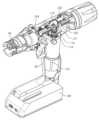
도 2을 참조하면, 수술용 스테이플링 시스템에 대한 전동 핸들의 일 실시예가 예시된다. 전동 핸들은, 샤프트 구성, 조 어셈블리 구성, 및 스테이플 구성이 특정 절차를 위하여 선택될 수 있도록 다양한 샤프트 재장전물들 및 카트리지들과 함께 사용될 수 있다. 핸들의 예시된 실시예는 전동(모터-드라이브형) 클램핑 및 조들의 폐쇄와 스테이플 라인의 발사를 제공한다. 조 어셈블리의 관절은 수술자가 회전시키는 관절 손잡이에 의해 수동으로 제어될 수 있다. 모터는, 상이한 사용 단계 동안 핸들의 기능을 지시하는 내장형 제어 시스템에 의해 제어된다.Referring to FIG. 2 , one embodiment of a powered handle for a surgical stapling system is illustrated. Powered handles can be used with a variety of shaft reloads and cartridges so that the shaft configuration, jaw assembly configuration, and staple configuration can be selected for a particular procedure. The illustrated embodiment of the handle provides electric (motor-driven) clamping and closing of the jaws and firing of the staple line. The joint of the jaw assembly may be manually controlled by an operator rotating the joint handle. The motor is controlled by a built-in control system that directs the function of the handle during different phases of use.
계속해서 도 2를 참조하면, 전동 핸들(40)은 고정식 핸들(42) 및 이에 피봇가능하게 결합된 이동가능 핸들(44) 또는 트리거를 갖는 피스톨-그립 구성을 포함한다. 전원 공급장치(130) 또는 배터리는 고정식 핸들의 하부 표면 상에 위치될 수 있다. 전동 핸들(40)은 사용자가 스테이플링 시퀀스를 선택적으로 제어하는 것을 가능하게 하기 위한 발사 또는 발사/역전(fire/reverse) 버튼(150)과 같은 사용자 제어부를 더 포함할 수 있다. 전동 핸들(40)은, 전동 시스템 고장, 제어 시스템 고장, 전원 공급장치 고장, "조잠김(lockjaw)" 또는 다른 기계적인 묶임(binding)의 경우에 사용자가 수동으로 스테이플링 시스템을 개방 구성으로 복귀시키는 것을 가능하게 하기 위한 여분의 수동 복귀 시스템(170)을 더 포함할 수 있다. 전동 핸들은 회전가능 관절 손잡이(190)를 포함하는 수동 관절 메커니즘을 더 포함할 수 있다. 예시된 실시예에서, 관절 손잡이(190)는 전동 핸들의 근위 단부 상에 위치되며, 전반적으로 스테이플링 시스템의 길이 방향 축에 대응하는 축에 대해 회전가능하다. 일부 실시예들에서, 전동 핸들은 사용자에게 희망되는 상태 표시를 디스플레이하기 위한 환형 조명 링과 같은 조명형 사용자 디스플레이를 더 포함할 수 있다.With continuing reference to FIG. 2 ,
전동 핸들 어셈블리들 및 연관된 작동 메커니즘들의 다양한 실시예들은 "Reload Shaft Assembly for Surgical Stapler"라는 명칭으로 2017년 04월 12일자로 출원된 미국 특허 출원 일련번호 제15/486,227호 및 "Surgical Stapler Having a Powered Handle"이라는 명칭으로 2017년 04월 12일자로 출원된 미국 특허 출원 일련번호 제15/486,008호에 개시되며, 이러한 출원들 둘 모두는 그 전체가 본원에 참조로서 통합된다.Various embodiments of powered handle assemblies and associated actuation mechanisms are described in U.S. Patent Application Serial No. 15/486,227, filed on April 12, 2017, entitled "Reload Shaft Assembly for Surgical Stapler" and "Surgical Stapler Having a Powered Stapler". Handle," filed on April 12, 2017, US Patent Application Serial No. 15/486,008, both of which are incorporated herein by reference in their entirety.
전동 드라이브 시스템electric drive system
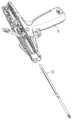
도 3을 참조하면, 전동 핸들의 부분 절개도가 예시된다. 예시된 절개도에서, 전동 핸들의 몇몇 구성요소들은 전동 핸들의 드라이브 시스템을 명확하게 도시하기 위하여 제거되었다. 예시된 실시예에서, 드라이브 시스템은 고정식 핸들(42) 내에 위치된 모터(112), 모터(112)의 출력 샤프트 상에 위치된 모터 기어(114), 및 모터 기어(114)와 드라이브 맞물림되는(driven engagement) 보조 기어(116)를 포함한다. 일부 실시예들에서, 모터(112)는 브러시형(brushed) DC 기어모터이다. 유익하게는, 보조 기어(116)를 통해 전력을 전달하는 것은 핸들 밸런스 및 사용자 인체공학을 향상시키기 위하여 모터(112)가 고정식 핸들 내에서 측방으로 중심에 위치되는 것을 가능하게 할 수 있다. 추가로, 일부 실시예들에서, 모터 기어(114) 및 보조 기어(116)는 랙(122)에서 희망되는 동작 토크를 제공하도록 구성될 수 있다. 일부 실시예들에서, 모터(112)는 희망되는 동작 토크를 제공하기 위하여 보조 기어(116)에 결합된 모터 기어(114)와 모터(112) 사이에 동작가능하게 결합되는 다중기어 트랜스미션(multigear transmission)을 포함할 수 있다. 모터(112)는 제어 시스템을 통해 전원 공급장치(130)에 전기적으로 결합될 수 있다. 핸들 내의 제어 시스템은 작동 샤프트(120)의 위치 및 그에 따른 조 어셈블리의 작동을 측정하기 위하여 드라이브 시스템과 인터페이스한다.Referring to FIG. 3 , a partial cutaway view of the powered handle is illustrated. In the illustrated cut-away view, some components of the powered handle have been removed to clearly show the drive system of the powered handle. In the illustrated embodiment, the drive system includes a
드라이브 시스템은, 핸들 내의 마이크로제어기를 포함하는 제어 시스템에 정보를 제공하는 하드웨어에 장착된다. 이러한 내장형 시스템은 모터의 속도(speed) 및 토크를 제어할 수 있다. 이는 또한 사용자 입력들(트리거의 움직임 및 발사/역전 버튼의 눌림)에 기초하여 디바이스의 기능 및 드라이브 시스템의 위치를 제어할 수 있다. 제어 시스템은 또한 스테이플들을 계속해서 발사하기에 부하들이 너무 큰지 여부 또는 재장전물 카트리지 락아웃(lockout)이 활성화되었는지 여부를 결정하기 위하여 모터로부터의 피드백을 측정할 수 있다. 이는 또한 배터리 수명을 측정할 수 있으며, 디바이스의 발사 횟수를 제한할 수 있다. 드라이브 시스템이 주로 전동 동작들을 위하여 구성되지만, 특정 실시예들에서, 본원에서 추가로 설명되는 바와 같이 오버라이드 전동 동작에 수동 복귀 메커니즘을 제공하는 것이 바람직할 수 있다.The drive system is mounted on hardware that provides information to a control system including a microcontroller in the handle. This built-in system can control the speed and torque of the motor. It may also control the function of the device and the position of the drive system based on user inputs (move the trigger and press the fire/reverse button). The control system may also measure feedback from the motor to determine if the loads are too great to continue firing staples or if a reload cartridge lockout has been activated. It can also measure battery life and limit the number of shots the device has. Although the drive system is primarily configured for motorized operations, in certain embodiments it may be desirable to provide a manual return mechanism to override motorized operations as described further herein.
계속해서 도 3을 참조하면, 예시된 실시예에서, 드라이브 시스템은, 지지 플레이트(121)에 의해 이것의 종점들 사이에서 지지되는 두 갈래형(bifurcated) 보조 기어(116)를 포함한다. 유익하게는, 보조 기어(116)에 대한 이러한 지지형 배열은, 무거운 부하 조건들에서 모터 기어(114)가 보조 기어(116)로부터 분리되는 경향을 상당히 감소시킬 수 있는 견고한 메커니즘을 제공한다. 다른 실시예들에서, 드라이브 시스템은 두 갈래형이 아닌 보조 기어를 포함할 수 있다.With continued reference to FIG. 3 , in the illustrated embodiment, the drive system includes a bifurcated
수동 오버라이드 복귀 시스템Manual override return system
도 4 내지 도 12c를 참조하면, 전동 핸들에 대한 수동 복귀 메커니즘의 일 실시예가 예시된다. 수동 복귀 메커니즘은 유익하게는, 전원 공급장치 고장, 다른 전동 구성요소 고장, 또는 기계적 고장 또는 묶임의 경우에 여분의 복귀 메커니즘을 제공할 수 있다.Referring to Figures 4-12C, one embodiment of a manual return mechanism for a powered steering wheel is illustrated. A manual return mechanism may advantageously provide a redundant return mechanism in case of power supply failure, other transmission component failure, or mechanical failure or binding.
도 4 내지 도 11을 참조하면, 수동 복귀 메커니즘은, 작동 샤프트(120)를 조 어셈블리의 개방 구성에 대응하는 핸들 내의 최-근위 위치로 복귀시키기 위한 시퀀스로 동작되는 3개의 별개의 독립적으로 동작가능한 서브어셈블리들을 포함한다. 예시된 바와 같이, 수동 복귀 메커니즘(170)은 복귀 잠금 메커니즘, 샤프트 회전 메커니즘 및 샤프트 후퇴 메커니즘을 포함한다. 도 4는, 복귀 잠금 메커니즘이 잠긴 구성에 있는 상태의 전동 동작 모드의 전동 핸들을 예시한다. 동작 시에, 수동으로 스테이플러를 개방 구성으로 복귀시키는 것이 바람직할 때, 복귀 잠금 메커니즘은 처음에 수동 복귀 메커니즘을 잠금 해제하도록 작동된다.Referring to Figures 4-11, the manual return mechanism comprises three separate, independently operable, actuated in sequence to return the
도 5 내지 도 6에 예시된 바와 같이, 복귀 잠금 메커니즘을 작동시키기 위해, 복귀 잠금부(171)는 처음에 핸들 어셈블리의 하우징에 대해 근위로 슬라이드된다. 복귀 잠금부(171)의 이러한 움직임은 샤프트 회전 메커니즘 및 샤프트 후퇴 메커니즘을 잠금 해제한다. 예시된 실시예에서, 복귀 잠금부(171)는, 이것이 샤프트 회전 메커니즘의 움직임을 간섭하는 위치에서 벗어나도록 이동되며, 이는 사용을 위하여 샤프트 회전 메커니즘을 노출시킨다. 동시에, 복귀 잠금부(171)는 샤프트 후퇴 메커니즘 상의 잠금 돌출부들(173) 또는 탭들로부터 분리되며, 이는 샤프트 후퇴 메커니즘이 핸들 어셈블리로부터 멀어지도록 피봇하는 것을 가능하게 한다. 샤프트 후퇴 메커니즘의 레버는 핸들 어셈블리로부터 멀어지도록 편향될 수 있으며, 이는 이것이 복귀 잠금부가 근위로 슬라이드될 때 핸들 어셈블리로부터 멀어지도록 피봇하게끔 한다.5-6, to activate the return lock mechanism, the
도 7 및 도 8을 참조하면, 복귀 잠금부가 복귀 메커니즘을 잠금 해제하기 위해 근위로 슬라이드될 때, 복귀 잠금부(171)는 핸들 어셈블리의 전원을 차단하기 위해 핸들 어셈블리의 제어 유닛에 전기적으로 결합될 수 있다. 따라서, 일단 복귀 잠금 메커니즘이 동작되면, 핸들은, 심지어 사용자가 반복 사용을 위해 수동 복귀 메커니즘 및 드라이브 시스템을 수동으로 재위치시키려고 시도하는 경우에도 추가적인 사용으로부터 디세이블될 수 있다. 예시된 실시예에서, 핸들 어셈블리가 전동 동작을 위해 구성될 때(도 7), 복귀 잠금부는 제어 유닛을 갖는 회로 보드(144)로부터 전기적으로 분리된다. 특정 실시예들에서, 복귀 잠금부가 복귀 메커니즘을 잠금 해제하기 위해 근위로 슬라이드될 때, 복귀 잠금부는, 핸들 어셈블리의 전원을 차단하기 위해 회로 보드(144) 상의 회로에 전기적으로 맞물리는 압인된(stamped) 스프링 구성요소(175)를 근위로 움직인다. 스프링 구성요소(175)는 근위 움직임만을 위해 구성되며, 심지어 복귀 잠금부가 이것의 초기 위치로 원위로 복귀되는 경우에도 원위로 복귀하지 않는다. 따라서, 복귀 잠금부(171)를 슬라이드함으로써 복귀 메커니즘을 잠금 해제하는 것은 핸들 어셈블리의 전동 기능을 영구적으로 디세이블한다.7 and 8, when the return lock is slid proximally to unlock the return mechanism, the
도 9 및 도 10을 참조하면, 수동 복귀 메커니즘(170)의 샤프트 회전 메커니즘을 동작시키기 위해, 사용자는, 이제 복귀 잠금부의 움직임에 의해 차단이 해제된, 핸들의 외부 표면으로 연장되는 회전 레버(172)를 회전시킨다. 회전 레버(172)는 작동 샤프트에 회전가능하게 결합된 샤프트 회전 칼라(collar)에 결합된다. 예시된 실시예에서, 작동 샤프트(120)는 샤프트 회전 칼라(176)를 통해 연장되며, 이를 통해 슬라이드가능하다. 따라서, 샤프트 회전 칼라(176)를 회전시키는 것은 작동 샤프트(120)를 이것의 길이 방향 축에 대해 약 90도 회전시킨다. 이러한 회전은 작동 샤프트의 랙(122)을 드라이브 시스템의 보조 기어(116)와의 맞물림으로부터 벗어나도록 위치시킨다. 이러한 회전은 작동 어댑터에 영향을 주지 않고 달성될 수 있으며, 이는 작동 샤프트(120)가 작동 어댑터에 회전가능하게 결합되기 때문이다(도 3). 특정 실시예들에서, 작동 샤프트는, 작동 샤프트(120)가 보조 기어(116)로부터 랙(122)을 분리하기 위해 회전될 때, 리세스된 외부 표면(124)이 보조 기어(116)로부터 이격되도록, 랙(122)에 인접하여 연장되는 리세스된 외부 표면(124)을 포함한다.Referring to Figures 9 and 10, to operate the shaft rotation mechanism of the
예시된 실시예가 사용자에 의해 회전되는 회전 레버(172)를 갖는 샤프트 회전 메커니즘을 포함하지만, 다른 실시예들에 있어서, 샤프트 회전 메커니즘은 복귀 잠금부의 근위 움직임 시에 자체-전개(self-deploy)하도록 구성될 수 있다. 예를 들어, 샤프트 회전 메커니즘을 자체-전개하는 것은 비틀림 편향을 갖는 샤프트 회전 칼라를 포함할 수 있다. 특정 실시예들에서, 샤프트 회전 칼라는 비틀림 스프링에 의해 핸들 어셈블리에 결합된다. 복귀 잠금부가 근위로 슬라이드될 때, 샤프트 회전의 비틀림 편향은 작동 랙을 보조 기어로부터 분리하고 작동 랙을 샤프트 후퇴 메커니즘과 맞물리게 하기 위해 작동 랙을 회전시키는 경향이 있다.Although the illustrated embodiment includes a shaft rotation mechanism with a
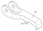
도 10 및 도 11을 참조하면, 일단 샤프트 회전 메커니즘이 동작되었으면, 샤프트 후퇴 메커니즘이 작동 샤프트를 핸들 내에서 근위로 복귀시키도록 동작될 수 있다. 복귀 잠금부를 핸들 어셈블리 내에서 근위로 슬라이드시키는 것은 전동 핸들 상의 복귀 레버(180)를 잠금 해제한다. 복귀 레버(180)는 피봇 조인트(184)에서 복귀 폴(182)에 피봇가능하게 결합된다. 작동 샤프트(120)의 랙(122)이 드라이브 시스템과의 맞물림을 벗어나도록 회전되었을 때, 이는 샤프트 후퇴 메커니즘과 맞물리도록 회전된다. 복귀 레버(180)는, 복귀 폴(182)을 작동 샤프트(120) 상의 랙(122)과 맞물리게 하고 작동 샤프트(120)를 래칫-형(ratchet-type) 동작으로 핸들 내에서 근위로 후퇴시키기 위해 하나의 또는 일련의 복귀 사이클들(도 10, 도 11)을 통해 회전될 수 있다.Referring to Figures 10 and 11, once the shaft rotation mechanism has been operated, the shaft retraction mechanism can be operated to return the actuation shaft proximally within the handle. Sliding the return lock proximally within the handle assembly unlocks the
도 12a 내지 도 12c를 참조하면, 복귀 폴(182)은 작동 샤프트 후퇴를 용이하게 하도록 구성될 수 있다. 예시된 실시예에서, 복귀 폴(182)은, 복귀 사이클의 일 부분 동안 모터 마운트의 가이드 부재(127)와 상호작용하도록 위치된 돌출 돌기 또는 제2 폴 톱니(tooth)(183)를 포함한다. 전동 동작 동안, 제2 폴 톱니(183)는 가이드 부재(127)와 접촉하며, 복귀 폴(182)은 작동 샤프트(120)의 랙(122)과 맞물리는 것이 제한된다(도 12b). 바람직하게는, 제2 폴 톱니(183)는, 사용자가 그렇지 않았다면 상대적으로 낮은 기계적 장점을 가졌을, 복귀 사이클의 일 부분 동안 랙(122)과의 복귀 폴(182)의 맞물림을 제한하도록 위치될 수 있다. 예시된 바와 같이, 제2 폴 톱니(183)는, 복귀 레버(180)가 희망되는 기계적 장점을 제공하기 위해 작동 샤프트(120)의 길이 방향 축에 대하여 미리 결정된 각도로 위치될 때까지(도 12c), 복귀 폴(182)이 랙(122)과 맞물리는 것을 방지한다.Referring to FIGS. 12A-12C , return
도 13을 참조하면, 수술용 스테이플러에 대한 핸들 어셈블리(40)의 부분 절개 사시도가 예시된다. 전동 동작에서, 핸들 어셈블리의 작동 샤프트(120)는 엔드 이펙터(end effector)의 조들을 클램핑하고 하나 이상의 발사 사이클들에 걸쳐 스테이플들을 발사하기 위해 드라이브 시스템에 동작가능하게 결합된 상태로 유지된다. 드라이브 시스템으로부터 작동 샤프트를 분리하고 작동 샤프트를 근위 위치로 복귀시키기 위해 수동 복귀 메커니즘이 작동되어야 하는 경우, 특정 경우들에서, 수동 복귀 메커니즘의 동작 및 핸들 어셈블리(40)로부터의 세장형 샤프트의 제거 이후에, 작동 샤프트(120)는 드라이브 시스템 및 수동 복귀 메커니즘 둘 모두로부터 분리되게 될 수 있다. 이러한 상황들에서, 작동 샤프트는 원위로 부분적으로 또는 완전히 핸들 어셈블리 밖으로 이동할 수 있다. 예를 들어, 핸들 어셈블리(40)가 원위 단부가 아래쪽으로 지향된 상태로 배향된 경우, 특정 경우들에서, 작동 샤프트(120)의 중량은 작동 샤프트를 핸들 어셈블리에 대해 원위로 이동하게 할 수 있다. 도 13은, 작동 샤프트가 완전히 핸들 어셈블리 밖으로 원위로 이동된 상태의 핸들 어셈블리를 예시한다. 수동 복귀 메커니즘의 작동 및 세장형 샤프트의 분리 이후에만 발생하는 이러한 상태는 환자에게 위험을 초래하지 않지만, 수동 복귀 메커니즘의 작동 이후에 핸들 어셈블리의 완전성을 유지하는 것이 바람직하다. 그러나, 특정 실시예들에서, 핸들 어셈블리(40)가, 수동 복귀 메커니즘의 동작 다음에 작동 샤프트(120)의 원위 움직임의 가능성을 방지하거나 또는 감소시키기 위한 유지 메커니즘을 더 포함하는 것이 바람직하다.Referring to FIG. 13 , a partially cut-away perspective view of a
작동 샤프트 유지 메커니즘working shaft retaining mechanism
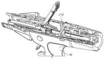
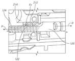
도 14 내지 도 19를 참조하면, 수동 복귀 메커니즘에 대한 유지 메커니즘(210)의 일 실시예의 특정 측면들이 예시된다. 예시된 실시예에서, 유지 메커니즘(210)은, 수동 복귀 메커니즘에 의해 맞물릴 때 근위 방향으로의 작동 샤프트의 움직임을 허용하고 원위 방향으로의 작동 샤프트의 움직임을 제한하도록 위치된 페더보드(featherboard)-형의 복수의 핀들(212) 또는 립(rib)들을 포함한다.14-19, certain aspects of one embodiment of a
도 14 내지 도 15를 참조하면, 특정 실시예들에서, 복수의 핀들(212)은 인접한 작동 샤프트(120)를 하우징하는 핸들 어셈블리(40) 내에 배치될 수 있다. 예시된 바와 같이, 일부 실시예들에서, 복수의 핀들(212)을 포함하는 페더보드 기하구조는 핸들 어셈블리(40) 내의 작동 샤프트(120)에 대한 지지 하우징(214)과 일체로 형성될 수 있다. 예를 들어, 특정 실시예들에서, 지지 하우징(214)은 사출 성형 프로세스에 의해 형성될 수 있으며, 복수의 핀들(212)은 지지 하우징(214)과 함께 사출 성형될 수 있다.Referring to FIGS. 14-15 , in certain embodiments, a plurality of
계속해서 도 14 내지 도 15를 참조하면, 예시된 실시예에서, 페더보드 기하구조는, 작동 샤프트(120)의 길이 방향 축에 대해 횡방향 각도로 배열된 복수의 핀들(212) 또는 립(rib)들을 포함한다. 복수의 핀들(212)의 이러한 횡방향 배열은 바람직하게는 작동 샤프트(120)에 방향 의존 마찰력을 부여할 수 있다. 복수의 핀들(212)이 작동 샤프트(120)와 접촉하면, 복수의 핀들(212)은 작동 샤프트가 핸들 어셈블리에 대해 근위 방향으로 이동될 때 작동 샤프트(212)에 제1 마찰력을 부여하고, 작동 샤프트가 핸들 어셈블리에 대해 원위 방향으로 이동될 때 제1 마찰력보다 더 큰 제2 마찰력을 부여한다. 따라서, 바람직하게는, 복수의 핀들(212)의 횡방향 각도 구성은 작동 샤프트를 핸들 어셈블리 내에서 근위로 복귀시키기 위해 수동 복귀 메커니즘에 가해지는 입력 힘에 대한 추가적인 마찰력들에 상대적으로 작은 영향을 가질 수 있다. 그러나, 작동 샤프트는 제2 마찰력에 의해 핸들 어셈블리 내에서 원위로 이동하는 것이 제한된다.With continued reference to FIGS. 14-15 , in the illustrated embodiment, the featherboard geometry comprises a plurality of
도 16을 참조하면, 핸들 어셈블리에 대한 지지 하우징(214)의 일 실시예에 배치된 작동 샤프트(120)의 일 실시예가 예시된다. 도 16의 실시예에서, 작동 샤프트와 지지 하우징의 상호작용의 특정 측면들의 시각화를 향상시키기 위해 작동 샤프트(120) 및 지지 하우징(214)만이 예시되고 핸들 어셈블리의 다른 구성요소들은 숨겨진다. 예시된 실시예에서, 작동 샤프트(120)는 수동 복귀 메커니즘을 이용한 핸들 어셈블리에 대한 근위 복귀를 위한 복귀 배향으로 회전된다. 작동 샤프트(120)는 또한, 수동 복귀 메커니즘의 완전 작동에 대응하는 완전히 근위로 후퇴된 위치에 예시된다. 예시된 바와 같이, 지지 하우징(214)은, 지지 하우징(214)의 표면에 형성되며 작동 샤프트(120)와 접촉하도록 위치된 복수의 립들 또는 핀들(212)을 포함하는 페더보드 기하구조를 갖는 유지 메커니즘을 포함한다. 예시된 바와 같이, 복수의 립들은 작동 샤프트(120)의 길이 방향 축에 대해 횡방향 각도로 연장되며, 작동 샤프트(120)에 접촉력(Fc)를 가한다. 따라서, 복수의 립들은 작동 샤프트 상에 방향 의존 마찰력을 부여한다. 수동 복귀 메커니즘이 작동될 때와 같이 작동 샤프트가 지지 하우징에 대해 근위 방향(P)으로 이동될 때, 유지 메커니즘은 작동 샤프트에 제1 마찰력을 부여한다. 작동 샤프트가 지지 하우징에 대해 원위 방향(D)으로 이동될 때, 유지 메커니즘은 작동 샤프트에 제1 마찰력보다 더 큰 제2 마찰력을 부여한다.Referring to Fig. 16, one embodiment of an
도 17을 참조하면, 핸들 어셈블리에 대한 페더보드 기하구조의 실시예의 상세도가 예시된다. 예시된 바와 같이, 페더보드 기하구조는 복수의 핀들(212) 또는 립들을 포함한다. 복수의 립들 중 인접한 립들은 갭(216)에 의해 분리된다. 각각의 갭은 복수의 립들 중 하나의 립의 팁에 인접한 개방 단부(218) 및 복수의 립들 중 하나의 립의 루트(root)에 인접한 폐쇄 단부(220)를 포함한다. 일부 실시예들에서, 갭은 인접한 립들의 쌍을 완전히 분리한다. 다른 실시예들에서, 갭은 인접한 립들의 쌍의 일 부분을 분리할 수 있으며, 립들은 다른 부분을 통해 결합될 수 있다. 예를 들어, 립들은 지지 하우징으로부터 소정의 높이로 연장될 수 있다.Referring to Fig. 17, a detailed view of an embodiment of a featherboard geometry for a handle assembly is illustrated. As illustrated, the featherboard geometry includes a plurality of
계속해서 도 17을 참조하면, 특정 실시예들에서, 개방 단부는, 각각의 립이 작동 샤프트의 길이 방향 축에 대해 횡방향 각도(θ)로 축을 따라 연장되도록 대응하는 폐쇄 단부로부터 작동 샤프트의 길이 방향 축에 대해 길이 방향으로 변위된다. 특정 실시예들에서, 립은 작동 샤프트의 길이 방향 축에 대해 약 30도 내지 75도 사이의 각도로 연장될 수 있다. 더 바람직하게는, 립은 약 45도 내지 70도 사이의 각도로 연장될 수 있다. 바람직하게는, 립은 약 55도 내지 65도 사이의 각도로 연장될 수 있다. 다른 실시예들에서, 립은 작동 샤프트의 길이 방향 축에 대해 30도보다 작거나 또는 75도보다 큰 각도로 연장될 수 있다. 예시된 실시예에서, 페더보드 기하구조는 서로 평행한 2개의 갭들(216)을 포함한다. 다른 실시예들에서, 각각의 갭은 작동 샤프트의 길이 방향 축에 대해 상이한 각도로 연장될 수 있다는 것이 고려된다.With continued reference to FIG. 17 , in certain embodiments, the open end extends along the axis at a transverse angle θ relative to the longitudinal axis of the actuation shaft so that each lip extends along a length of the actuation shaft from a corresponding closed end. It is displaced in the longitudinal direction with respect to the directional axis. In certain embodiments, the lip may extend at an angle between about 30 and 75 degrees relative to the longitudinal axis of the actuating shaft. More desirably, the lip may extend at an angle between about 45 and 70 degrees. Preferably, the lip may extend at an angle between about 55 and 65 degrees. In other embodiments, the lip may extend at an angle of less than 30 degrees or greater than 75 degrees with respect to the longitudinal axis of the actuating shaft. In the illustrated embodiment, the featherboard geometry includes two
계속해서 도 17을 참조하면, 예시된 실시예에서, 페더보드 기하구조는 그 사이에 립들을 획정하는 2개의 갭들(216)을 포함한다. 다른 실시예들에서, 유지 메커니즘에서 사용하기 위한 페더보드 기하구조는 그 사이에 립들을 획정하는 3개 이상의 갭들을 포함할 수 있다. 또한, 예시된 실시예에서 페더보드 기하구조가 핸들 어셈블리의 지지 하우징 구성요소로 성형되지만, 다른 실시예들에서, 페더보드 구성요소가 별개로 형성되고 지지 하우징에 결합되거나 또는 체결될 수 있다는 것이 고려된다.With continued reference to FIG. 17 , in the illustrated embodiment, the featherboard geometry includes two
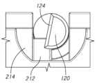
도 18 내지 도 19를 참조하면, 핸들 어셈블리에 대한 지지 하우징(214)의 일 실시예에 배치된 작동 샤프트(120)의 일 실시예가 예시된다. 도 18 및 도 19는, 작동 샤프트(120)가 수동 복귀 메커니즘의 작동을 위해 배향된 상태(도 19)와 비교하여 작동 샤프트(120)가 전동 작동을 위해 배향된 상태(도 18)의 지지 하우징(214) 내의 작동 샤프트(120)의 절개 단부도를 예시한다. 유지 메커니즘은, 유지 메커니즘이 핸들 어셈블리의 전동 동작과 간섭하는 것이 아니라, 일단 수동 복귀 메커니즘이 작동되면 원위 이동으로부터 작동 샤프트를 유지하도록 배열되는 것이 바람직하다. 특정 실시예들에서, 페더보드 기하구조는 작동 샤프트가 전동 동작을 위해 배향될 때 작동 샤프트(120)로부터 이격된 위치에서 핸들 어셈블리 내에 배치될 수 있으며, 작동 샤프트가 수동 복귀 메커니즘의 동작을 위한 배향으로 회전되었을 때 작동 샤프트와 맞물릴 수 있다. 18-19, one embodiment of an
도 18을 참조하면, 작동 샤프트가 핸들 어셈블리의 전동 동작을 위해 배향된 상태에서, 특정 실시예들에서, 유지 메커니즘의 립들은 작동 샤프트(120)의 리세스된 외부 표면(124)과 정렬된 위치에서 지지 하우징(214) 내에 위치될 수 있다. 따라서, 유지 메커니즘은, 작동 샤프트가 핸들 어셈블리의 전동 동작을 위해 배향될 때 작동 샤프트(120)와 맞물리지 않고, 이는 드라이브 시스템에 응답하는 작동 샤프트의 근위 및 원위 이동을 허용한다.Referring to FIG. 18 , with the actuation shaft oriented for powered operation of the handle assembly, in certain embodiments, the lips of the retaining mechanism are in a position aligned with the recessed
도 19를 참조하면, 작동 샤프트(120)가 수동 복귀 메커니즘을 이용한 작동 샤프트의 후퇴를 위해 배향된 상태에서, 유지 메커니즘의 립들은 작동 샤프트(120)의 외부 표면의 일 부분과 맞물린 위치에서 지지 하우징(214) 내에 위치된다. 따라서, 작동 샤프트(120)가 수동 복귀 메커니즘을 이용한 작동을 위해 배향된 상태에서, 유지 메커니즘은 작동 샤프트(120)에 마찰력을 부여한다. Referring to FIG. 19 , with the
도 20을 참조하면, 수동 복귀 메커니즘에 대한 유지 메커니즘의 일 실시예의 특정 측면들이 예시된다. 유지 메커니즘은, 수동 복귀 메커니즘이 작동되었을 때 핸들 어셈블리의 작동 샤프트와 맞물리도록 편향된 플런저(plunger)(230)를 포함한다. 특정 실시예들에서, 플런저(230)는 작동 샤프트(120)를 향해 플런저의 팁을 편향시키도록 위치된 스프링(232)에 의해 편향된다. 특정 실시예들에서, 플런저(230)는, 작동 샤프트가 전동 동작을 위해 배향된 상태에서 플런저가 작동 샤프트(120)의 외부 표면으로부터 이격되도록 핸들 어셈블리 내의 위치에 배치될 수 있다. 예를 들어, 플런저(230)는 작동 샤프트가 전동 동작을 위해 배향된 상태에서 작동 샤프트(120)의 외부 표면의 리세스 내에 위치될 수 있다. 특정 실시예들에서, 플런저(230)는, 반경형(radiused) 팁이 작동 샤프트에 바람직하지 않은 마찰력을 부여하지 않으면서 반경형 팁이 전동 동작을 위해 배향된 작동 샤프트(120)의 외부 표면과 맞물릴 수 있도록 반경형 또는 볼 팁(236)을 가질 수 있다. 특정 실시예들에서, 플런저(230)의 볼 팁(236)은 작동 샤프트의 외부 표면과 직접적으로 맞물릴 수 있다. 특정 실시예들에서, 작동 샤프트(120)는, 작동 샤프트(120)가 수동 복귀 메커니즘의 작동을 위해 배향되고 작동 샤프트(120)가 근위로 후퇴된 상태에서 플런저(230)와 맞물리도록 위치된 홈 또는 딤플(dimple)(238)을 포함할 수 있다. 예를 들어, 특정 실시예들에서, 딤플(238)은 작동 샤프트(120)의 랙(122)에 대해 대체로 직경 방향으로 반대편의 위치에 배치될 수 있다. 따라서, 볼 또는 반경형 팁 플런저를 포함하는 유지 메커니즘의 실시예들에서, 플런저(230)는 작동 샤프트(120)를 핸들 어셈블리 내에 유지하기 위해 포지티브 디텐트 맞물림(positive detent engagement)으로 작동 샤프트(120)의 딤플(238)과 맞물릴 수 있다.Referring to FIG. 20 , certain aspects of one embodiment of a retention mechanism for a manual return mechanism are illustrated. The retention mechanism includes a
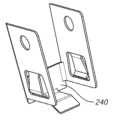
도 21 내지 도 22를 참조하면, 수동 복귀 메커니즘에 대한 유지 메커니즘의 일 실시예의 특정 측면들이 예시된다. 유지 메커니즘의 예시된 실시예는 작동 샤프트에 마찰력을 가하도록 배열되고 구성된 캔틸레버(cantilever) 부재를 포함한다. 특정 실시예들에서, 유지 메커니즘은 핸들 어셈블리에 장착가능한 스프링 몸체(240)를 포함할 수 있다. 스프링 몸체(240)는 리프 스프링(leaf spring)과 같은 방식으로 이로부터 연장되는 캔틸레버 부재(242)를 갖는 금속 재료 또는 플라스틱 재료를 포함할 수 있다. 캔틸레버 부재는 스프링 몸체(240)에 연결된 고정된 단부(244) 및 고정된 단부(244)에 대향되는 접촉 단부(246)를 가질 수 있다. 접촉 단부(246)는 작동 샤프트(120)에 접촉력을 가하도록 배열된다. 캔틸레버 부재(242)는, 작동 샤프트(120)가 근위 방향으로 후퇴될 때 작동 샤프트에 제1 마찰력을 가하고 작동 샤프트(120)가 원위로 이동될 때 제1 마찰력보다 더 큰 제2 마찰력을 가하도록 구성된다. 예를 들어, 일부 실시예들에서, 고정된 단부(244)는, 작동 샤프트가 근위 방향으로 이동될 때보다 작동 샤프트가 원위로 이동될 때 더 큰 경향이 있는 방향 의존 마찰력들 제공하기 위해 접촉 단부(246) 원위에 위치될 수 있다. 캔틸레버 부재에 의해 가해지는 마찰력들은, 드라이브 시스템에 상대적으로 작고 용인할 수 있는 부하만을 가하면서 작동 샤프트의 랙을 유지하기에 충분할 수 있다.Referring to Figures 21-22, certain aspects of one embodiment of a retention mechanism for a manual return mechanism are illustrated. The illustrated embodiment of the retaining mechanism includes a cantilever member arranged and configured to apply a frictional force to the actuating shaft. In certain embodiments, the retention mechanism may include a
도 21을 참조하면, 일부 실시예들에서, 스프링 몸체(240)는 작동 샤프트(120)의 일 부분을 부분적으로 또는 완전히 둘러싸도록 위치될 수 있다. 스프링 몸체(240)는, 작동 샤프트(120)와 슬라이드식으로 맞물려서 작동 샤프트에 마찰력을 생성하기 위해 고정된 단부(244)로부터 접촉 단부(246)까지 방사상으로 안쪽으로 연장되는 캔틸레버 부재(242)를 가질 수 있다. 예시된 실시예에서, 스프링 몸체(240)는 수동 복귀 메커니즘의 회전 레버(172)와 접하도록 위치된다. 다른 실시예들에서, 스프링 몸체(240)는 핸들 어셈블리 내의 다른 위치들에 위치될 수 있다.Referring to FIG. 21 , in some embodiments,
도 22를 참조하면, 일부 실시예들에서, 스프링 몸체(240)는 금속성 또는 플라스틱 재료의 시트로 형성될 수 있다. 재료의 시트는 핸들 어셈블리의 작동 샤프트와 슬라이드식으로 맞물리기 위해 리프 스프링과 같은 방식으로 편향되고 재료 시트와 함께 형성된 복수의 캔틸레버 부재들 중 하나를 갖는다. 특정 실시예들에서, 캔틸레버 부재는, 작동 샤프트(120)가 근위 방향으로 이동될 때 스프링 몸체에 의해 작은 마찰력만이 생성되지만 작동 샤프트가 원위 방향으로 이동될 때에는 캔틸레버 부재가 작동 샤프트(120) 상의 랙과 맞물리도록 래칫(ratchet)과 같은 방식으로 작동 샤프트(120)와 맞물리기 위해 작동 샤프트(120)의 랙과 맞물리도록 위치될 수 있다.Referring to FIG. 22 , in some embodiments,
도 23 내지 도 24를 참조하면, 수동 복귀 메커니즘에 대한 유지 메커니즘의 일 실시예의 특정 측면들이 예시된다. 예시된 실시예에서, 유지 메커니즘은 키퍼 디스크(keeper disc)(250)를 포함한다. 키퍼 디스크(250)는, 랙의 의도하지 않은 길이 방향 움직임을 방지하기 위해 작동 샤프트(120)의 랙(122)과의 맞물려 놓이는 재료의 플랩(flap)(252) 또는 스트립을 포함할 수 있다. 특정 실시예들에서, 키퍼 디스크(250)는 작동 샤프트가 이를 통해 연장되는 개구(254)를 갖는 재료의 시트를 포함한다. 재료의 플랩(252) 또는 스트립은 작동 샤프트(120)의 랙(122)과 맞물리기 위해 개구(254)에 인접하여 연장될 수 있다. 키퍼 디스크(250)는, 재료의 플랩(252) 또는 스트립을 구부리기 위한 힘이 상대적으로 작아서 전동 동작에서 그리고 수동 복귀 메커니즘의 작동 시에 랙의 작동을 허용하는 가요성 재료로 형성될 수 있다. 특정 실시예들에서, 키퍼 디스크(250)는 작동 샤프트(120)를 둘러싸거나 또는 봉입(encapsulate)할 수 있다. 특정 실시예들에서, 키퍼 디스크(250)는 핸들 어셈블리의 내부 구성요소에 부착될 수 있다. 예를 들어, 특정 실시예들에서, 키퍼 디스크(250)는 작동 샤프트(120)에 대한 지지 하우징에 부착될 수 있다. 다른 실시예들에서, 키퍼 디스크는 수동 복귀 메커니즘의 회전 레버(172)에 부착될 수 있다.Referring to Figures 23-24, certain aspects of one embodiment of a retention mechanism for a manual return mechanism are illustrated. In the illustrated embodiment, the retention mechanism includes a
도 25 내지 도 27을 참조하면, 수동 복귀 메커니즘에 대한 유지 메커니즘의 일 실시예의 특정 측면들이 예시된다. 도 25는, 복귀 레버(182)가 핸들 어셈블리에 인접한 상태의 제1 위치의 작동 샤프트(120) 및 수동 복귀 메커니즘을 예시한다. 도 26은, 복귀 레버(182)가 핸들 어셈블리로부터 이격된 제2 위치에 있는 상태의 작동 샤프트(120) 및 수동 복귀 메커니즘을 예시한다. 도 10 내지 도 11을 참조하여 논의된 바와 같이, 사용자는, 랙(122)과 복귀 폴(182)의 상호작용을 통해 작동 샤프트(120)를 근위로 후퇴시키기 위한 제2 위치와 제1 위치 사이에서 수동 복귀 메커니즘의 복귀 레버(180)를 순환시킬 수 있다. 수동 복귀 메커니즘이 제2 위치에 있을 때, 복귀 폴(182)은 작동 샤프트(120)의 랙(122)과 맞물린 상태로 유지된다. 복귀 폴(182)이 작동 샤프트(120)의 랙(122)과 맞물리면, 작동 샤프트(120)는 의도하지 않은 길이 방향 전진이 방지될 수 있다. 따라서, 특정 실시예들에서, 유지 메커니즘은, 근위 위치로 작동 랙으로 복귀시키기 위한 수동 복귀 메커니즘의 동작 다음에 수동 복귀 메커니즘의 폴을 작동 샤프트의 랙과 맞물린 상태로 유지하도록 배열되고 구성될 수 있다.Referring to Figures 25-27, certain aspects of one embodiment of a retention mechanism for a manual return mechanism are illustrated. 25 illustrates the
도 27을 참조하면, 수동 복귀 메커니즘에 대한 유지 메커니즘의 일 실시예의 특정 측면들이 예시된다. 예시된 실시예에서, 유지 메커니즘은 리프 스프링 어셈블리(260)를 포함한다. 리프 스프링 어셈블리(260)는 브래킷(262) 및 브래킷(262)으로부터 연장되는 스프링 암(arm)(264)을 포함할 수 있다. 브래킷(262)은, 수동 복귀 메커니즘의 작동 시에 스프링 암(264)이 복귀 레버(180)의 하부 표면과 접촉하고 레버를 핸들 어셈블리로부터 멀어지게 편향시키도록 복귀 레버(180)에 대한 피봇 조인트(186)에서 수동 복귀 메커니즘에 결합될 수 있다. 따라서, 복귀 레버(180)는 작동 샤프트(120)의 의도하지 않은 움직임을 방지하기 위해 수동 복귀 메커니즘의 복귀 폴(182)을 작동 샤프트(120)의 랙(122)과 접촉하는 상태로 유지하도록 편향된다. 다른 실시예들에서, 다른 스프링 배열들은 작동 샤프트(120)의 랙(122)과 맞물리도록 복귀 폴(182)을 편향시키기 위해 사용될 수 있다.Referring to FIG. 27 , certain aspects of one embodiment of a retention mechanism for a manual return mechanism are illustrated. In the illustrated embodiment, the retention mechanism includes
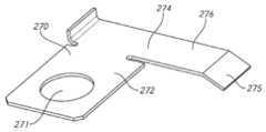
도 28 내지 도 29를 참조하면, 수동 복귀 메커니즘에 대한 유지 메커니즘의 일 실시예의 특정 측면들이 예시된다. 유지 메커니즘은, 작동 샤프트(120)가 수동 복귀 메커니즘을 이용한 작동을 위해 배향될 때 작동 샤프트(120)의 랙(122)과 맞물릴 수 있는 랙 폴(270)을 포함할 수 있다. 예시된 실시예에서, 랙 폴(270)은 작동 샤프트(120)에 인접하여 위치될 수 있는 브래킷(272) 및 브래킷(272)으로부터 연장되는 폴(274)을 포함한다. 예시된 바와 같이, 브래킷(272)은 핸들 어셈블리의 드라이브 시스템의 보조 기어(116) 상에 장착될 수 있는 개구(271)를 포함한다. 따라서, 예시된 실시예에서, 랙 폴(270)은 작동 샤프트가 전동 동작을 위해 배향될 때 작동 샤프트(120)의 랙(122)과 맞물리지 않으며, 랙 폴은 작동 샤프트가 수동 복귀 메커니즘의 동작을 위해 배향될 때 작동 샤프트의 랙과 맞물린다. 다른 실시예들에서, 브래킷은 핸들 어셈블리 내의 다른 구성요소들 또는 다른 곳 상에 배치되도록 구성될 수 있다.Referring to Figures 28-29, certain aspects of one embodiment of a retention mechanism for a manual return mechanism are illustrated. The retention mechanism may include a
계속해서 도 28 내지 도 29를 참조하면, 랙 폴(270)의 폴(274)은, 작동 샤프트(120)가 수동 복귀 메커니즘의 동작을 위해 배향된 상태에서 작동 샤프트(120)의 랙(122)과 맞물리도록 위치될 수 있다. 작동 샤프트(120)가 수동 복귀 메커니즘의 동작을 위한 배향으로 회전할 때, 폴(274)은 바람직하게는, 핸들 어셈블리에 대한 작동 샤프트(120)의 근위 후퇴를 허용하고 작동 샤프트(120)의 원위 전진을 제한하도록 구성될 수 있다. 특정 실시예들에서, 폴(274)은 브래킷(272)으로부터 연장되는 가요성 캔틸레버 암(276)의 단부에 배치된 폴 톱니(275)를 포함할 수 있다. 폴 톱니(275)는, 근위 방향으로의 작동 샤프트의 움직임을 허용하고 핸들 어셈블리에 대한 원위 방향으로의 작동 샤프트의 움직임을 제한하도록 각이 질 수 있다. 유지 메커니즘의 폴(274)의 폴 톱니(275)는, 수동 복귀 메커니즘의 복귀 폴(182)이 랙(122)과 맞물리는지 여부와 무관하게 작동 샤프트의 랙(122)과 맞물린 상태를 유지할 수 있다.With continuing reference to FIGS. 28-29 , the
도 30 내지 도 32를 참조하면, 수동 복귀 메커니즘에 대한 유지 메커니즘의 일 실시예의 특정 측면들이 예시된다. 특정 실시예들에서, 유지 메커니즘은, 수동 복귀 메커니즘에 의한 작동 샤프트의 후퇴 다음에 작동 샤프트의 원위 길이 방향 움직임을 제한하기 위해 작동 샤프트(120)의 일 부분과 맞물리도록 배열되고 구성된 캐치(catch) 어셈블리(280)를 포함할 수 있다. 도 30은, 작동 샤프트(120)가 핸들 어셈블리의 전동 동작을 위한 배향에 있는 상태에서 작동 샤프트(120) 및 캐치 어셈블리(280)의 상세 측면도를 예시한다. 작동 샤프트(120)가 작동 샤프트(120)의 전동 동작을 위해 배향될 때, 캐치 어셈블리(280)는 작동 샤프트(120)와 접촉하지 않는다. 예를 들어, 예시된 실시예에서, 캐치 어셈블리(280)는, 작동 샤프트(120)가 핸들 어셈블리의 전동 동작을 위해 배향될 때 작동 샤프트(120)의 리세스와 정렬되도록 핸들 어셈블리 내에 위치될 수 있다. 도 31 내지 도 32는, 작동 샤프트(120)가 수동 복귀 메커니즘을 이용한 후퇴를 위한 배향에 있으며 부분적으로 후퇴된 위치(도 31) 및 완전히 후퇴된 위치(도 32)에 있는 상태의 작동 샤프트(120) 및 캐치 어셈블리(280)의 상세 측면도를 예시한다.Referring to Figures 30-32, certain aspects of one embodiment of a retention mechanism for a manual return mechanism are illustrated. In certain embodiments, the retention mechanism includes a catch arranged and configured to engage a portion of the
계속해서 도 30 내지 도 32를 참조하면, 캐치 어셈블리(280)는, 이로부터 연장되는 캐치 레버(284)를 갖는 마운트 플레이트 또는 브래킷(282)을 포함할 수 있다. 브래킷(282)은 핸들 어셈블리의 지지 하우징 또는 그 내부에 위치된 다른 구성요소에 장착될 수 있다. 다른 실시예들에서, 캐치 어셈블리(280)는, 핸들 어셈블리의 지지 하우징에 직접적으로 장착되거나 또는 이와 일체로 형성된 캐치 레버(284)를 포함할 수 있다. 예를 들어, 다양한 실시예들에서, 캐치 어셈블리(280)는 핸들 어셈블리의 상단 지지부, 또는 핸들 어셈블리의 상단 또는 하단 하우징 부분에 장착되거나 또는 이와 일체로 형성될 수 있다. 다양한 실시예들에서, 캐치 어셈블리(280)는 금속 또는 플라스틱 재료를 포함할 수 있다.With continued reference to FIGS. 30-32 , the
도 31 내지 도 32를 참조하면, 작동 샤프트(120)는 내부에 형성된 리세스 또는 캐치 톱니(290)를 포함할 수 있다. 예시된 실시예에서, 작동 샤프트는 단일 근위 에지 또는 캐치 톱니(290)를 갖는 리세스를 포함한다. 다른 실시예들에서, 작동 샤프트는 작동 샤프트의 다양한 길이 방향 위치들에서 캐치 레버에 의해 맞물리도록 위치된 2개 이상의 캐치 톱니를 포함할 수 있다는 것이 고려된다.Referring to FIGS. 31 and 32 , the
계속해서 도 31 내지 도 32를 참조하면, 작동 샤프트(120)가 수동 복귀 메커니즘의 동작을 위해 배향될 때, 작동 샤프트(120)의 후퇴 동안, 캐치 레버(284)는 작동 샤프트(120)의 외부 표면과 접촉하고 이와 슬라이드식으로 맞물린다. 예시된 바와 같이, 리세스 및 캐치 톱니(290)는, 작동 샤프트가 수동 복귀 메커니즘의 동작을 위해 배향되고 근위로 후퇴될 때, 캐치 레버(284)가 캐치 톱니(290)와 맞물리도록 작동 샤프트(120) 상에 위치된다. 캐치 레버(284)가 캐치 톱니(290)와 맞물리면, 핸들 어셈블리에 대한 작동 샤프트(120)의 원위 움직임 시에, 캐치 레버(284)는 작동 샤프트(120)가 더 원위로 움직이는 것을 제한하기 위해 리세스의 캐치 톱니(290)와 맞물린다. 캐치 레버(284)는, 일단 캐치 레버가 작동 샤프트(120)의 리세스와 맞물리면, 캐치 레버(284)가 리세스의 리세스된 표면을 향해 편향되도록 작동 샤프트(120)를 향해 편향된 가요성 재료로 형성될 수 있다.With continued reference to FIGS. 31-32 , when the
도 33 내지 도 35를 참조하면, 수동 복귀 메커니즘에 대한 유지 메커니즘의 일 실시예의 특정 측면들이 예시된다. 예시된 실시예에서, 유지 메커니즘은, 작동 샤프트가 수동 복귀 메커니즘에 의한 동작을 위해 배향될 때, 작동 샤프트의 길이 방향 움직임에 대항하기 위한 마찰력이 작동 샤프트에 가해지도록 수동 복귀 메커니즘과 통합될 수 있다. 이러한 마찰력은 수동 복귀 메커니즘의 동작 다음에 작동 샤프트의 원위 움직임을 제한한다. 유지 메커니즘의 예시된 실시예는, 작동 샤프트(120)가 전동 동작을 위해 배향될 때(도 33) 추가적인 부하를 추가하지 않으면서, 작동 샤프트(120)가 수동 복귀 메커니즘에 의해 복귀되도록 배향된 상태(도 34)에서만 설명된 마찰력을 가하도록 구성된다. 특정 실시예들에서, 유지 메커니즘은, 작동 샤프트가 전동 동작을 위해 배향된 상태에서 작동 샤프트의 길이 방향 축으로부터 수동 복귀 메커니즘의 회전 축을 오프셋함으로써 수동 복귀 메커니즘에 통합될 수 있다.Referring to Figures 33-35, certain aspects of one embodiment of a retention mechanism for a manual return mechanism are illustrated. In the illustrated embodiment, the retention mechanism may be integrated with the manual return mechanism such that when the actuation shaft is oriented for operation by the manual return mechanism, a frictional force is applied to the actuation shaft to counter longitudinal movement of the actuation shaft. . This frictional force limits the distal movement of the actuation shaft following operation of the manual return mechanism. The illustrated embodiment of the retention mechanism is oriented so that the
도 33을 참조하면, 작동 샤프트(120)가 전동 동작을 위해 배향된 상태에서, 작동 샤프트(120)는 지지 하우징 또는 구동계 인클로저(300)의 중심 축(C)과 정렬된다. 따라서, 이러한 배향에서, 작동 샤프트(120)는, 유지 메커니즘에 의해 가해지는 마찰력 없이 전동 드라이브 시스템에 의해 길이 방향으로 드라이브될 수 있다.Referring to FIG. 33 , with the
도 34를 참조하면, 작동 샤프트(120)가 수동 복귀 메커니즘의 동작을 위한 배향으로 회전됨에 따라, 회전 레버(180)의 회전 축(R)과 지지 하우징 또는 구동계 인클로저(300)이 중심 축 사이의 오프셋은 도 35에 도시된 바와 같이 작동 샤프트를 지지 하우징 또는 구동 인클로저의 표면으로 강제한다. 따라서, 작동 샤프트가 수동 복귀 메커니즘의 동작을 위해 배향된 상태에서, 작동 샤프트는 지지 하우징 또는 구동 인클로저의 표면과 슬라이드식으로 맞물린다. 이러한 슬라이딩 맞물림은 수동 복귀 메커니즘의 동작 동안 그리고 그 다음에 작동 샤프트의 의도하지 않은 원위 움직임을 방지할 수 있다. 예시된 실시예는, 작동 샤프트가 수동 복귀 메커니즘의 동작을 위해 배향된 상태에서 작동 샤프트와 지지 하우징 사이의 맞물림 영역(304)에서 마찰력을 생성하기 위해 수동 복귀 메커니즘의 동작 동안 작동 샤프트의 회전 축 사이의 오프셋(302)을 포함하는 유지 메커니즘을 포함한다. 다른 실시예들에서, 유지 메커니즘은 수동 복귀 메커니즘의 동작을 위한 배향에 있는 작동 샤프트에 마찰력을 가하도록 배열될 수 있으며, 이는 회전 레버 및 구동계 인클로저 내의 캠(cam) 표면들의 사용을 통해 달성될 수 있다는 것이 고려될 수 있다.Referring to FIG. 34 , as the
도 36 내지 도 40을 참조하면, 수동 복귀 메커니즘에 대한 유지 메커니즘의 실시예들의 특정 측면들이 예시된다. 이러한 실시예들은, 도 33 내지 도 35를 참조하여 설명된 바와 같은 오프셋 회전 축을 갖는 유지 메커니즘의 실시예들과 유사하게, 수동 복귀 메커니즘의 작동 시에 작동 샤프트의 길이 방향 축에 수직인 수직력을 생성하도록 배열된다. 도 36 내지 도 40에 예시된 바와 같이, 일단 작동 샤프트(120)가 수동 복귀 메커니즘의 동작을 위해 회전되면, 랙 구성요소가 핸들 어셈블리 내의 크러시(crush) 특징부들(310)과 맞물려서 작동 샤프트가 자신의 중량으로 배출(expel)될 수 없도록 기계적 간섭이 이용된다. 바람직하게는, 크러시 특징부(310)는, 크러시 특징부가 전동 동작 동안 작동 샤프트(120)로부터 이격되도록 핸들 어셈블리 내에 위치된다. 따라서, 도 36에 예시된 바와 같이, 일부 실시예들에서, 크러시 특징부는, 작동 샤프트(120)가 전동 동작을 위해 배향된 상태에서 작동 샤프트(120)의 리세스(124) 내에 정렬되도록 위치된다. 작동 샤프트(120)가 수동 복귀 메커니즘에 의한 동작을 위해 회전될 때, 작동 샤프트(120)는 크러시 특징부(310)와 슬라이드식으로 맞물린다(도 37).Referring to Figures 36-40, certain aspects of embodiments of a retention mechanism for a manual return mechanism are illustrated. Similar to the embodiments of the retaining mechanism having an offset axis of rotation as described with reference to FIGS. 33-35 , these embodiments produce a normal force normal to the longitudinal axis of the actuating shaft upon actuation of the manual return mechanism. arranged so that 36-40, once the
도 38 내지 도 40을 참조하면, 다양한 실시예들에서, 핸들 어셈블리 내에 위치된 크러시 특징부(310)는 다수의 구성들을 취할 수 있다. 예를 들어, 도 38에 예시된 바와 같이, 특정 실시예들에서, 크러시 특징부(310)는 작동 샤프트의 길이 방향 축에 대해 횡방향으로 연장되는 하나 이상의 립들(312)을 포함할 수 있다. 하나 이상의 립들(312)은 작동 샤프트의 지지 하우징(214) 내에 위치될 수 있다. 도 39에 도시된 바와 같이, 일부 실시예들에서, 크러시 특징부(310)는 압축가능 반구형 돌출부(314)를 포함할 수 있다. 다른 실시예들에서, 도 40에 예시된 바와 같이, 크러시 특징부(310)는 지지 하우징(214) 내에서 길이 방향으로 연장되는 하나 이상의 립들(316)을 포함할 수 있다. 특정 실시예들에서, 크러시 특징부가 고무 재료를 포함하는 것이 고려된다. 도 38 내지 도 40이 핸들 어셈블리 내의 지지 하우징(214)의 일 부분으로부터 연장되는 다양한 돌출부들 및 립들을 예시하지만, 다른 실시예들에서, 유사한 특징부들은 핸들 어셈블리 내의 별개의 구성요소들로서 또는 다른 메이팅 구성요소들 내에 구현될 수 있다는 것이 고려된다.Referring to Figures 38-40, in various embodiments, the
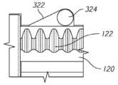
도 41 내지 도 43을 참조하면, 수동 복귀 메커니즘에 대한 유지 메커니즘의 일 실시예의 특정 측면들이 예시된다. 예시된 실시예에서, 유지 메커니즘은, 램프형(ramped) 또는 웨지(wedge) 잠금 리세스(322) 및 잠금 부재(324)를 갖는 1-방향 웨지 잠금 어셈블리(320)를 포함한다. 잠금 리세스(322)는 지지 하우징 내에 또는 작동 샤프트에 인접한 다른 핸들 어셈블리 구성요소 내에 형성될 수 있다. 도 41에 예시된 바와 같이, 작동 샤프트(120)가 전동 동작을 위해 배향된 상태에서, 잠금 부재(324)는 랙(122)으로부터 오프셋된 작동 샤프트(120)의 매끈한 외부 표면에 인접한 잠금 리세스(322) 내에 위치된다. 예시된 실시예에서, 잠금 부재(324)는, 전동 동작 동안 볼 베어링이 작동 샤프트(120)의 표면을 따라 매끄럽게 롤링하도록 볼 베어링을 포함할 수 있다. 다른 실시예들에서, 잠금 부재(324)는, 작동 샤프트(120)의 외부 표면을 따라 매끄럽게 이동할 수 있는 핀(pin) 또는 다른 슬라이딩 또는 롤링 부재를 포함할 수 있다. 도 42 내지 도 43을 참조하면, 작동 샤프트(120)가 수동 복귀 메커니즘의 동작을 위한 배향으로 회전될 때, 잠금 부재(324)는 작동 샤프트(120)의 랙(122) 내에 위치된다. 잠금 리세스(322)는, 핸들 어셈블리에 대한 작동 샤프트(120)의 원위 전진 시에, 잠금 부재(324)가 작동 샤프트의 추가적인 원위 움직임을 저지하기 위해 랙(122) 및 측벽(326)과 맞물리도록 위치된 테이퍼형, 램프형, 또는 웨지형 측벽(326)을 포함한다. 잠금 리세스(322)는, 웨지형 측벽 반대편의 제2 측벽(328) 및 제2 측벽(328)에서의 깊이(D)를 더 포함할 수 있다. 특정 실시예들에서, 잠금 리세스(322)는, 제2 측벽(328)에서의 깊이(D)가, 작동 샤프트(120)가 핸들 어셈블리에 대해 근위로 이동됨에 따라 잠금 부재(324)가 작동 샤프트(120)의 랙(122)을 따라 이동되는 것을 허용하도록 크기가 결정된다.Referring to Figures 41-43, certain aspects of one embodiment of a retention mechanism for a manual return mechanism are illustrated. In the illustrated embodiment, the retention mechanism includes a one-way wedge locking assembly 320 having a ramped or
특정 실시예들에서, 작동 샤프트 상의 마찰력 또는 드래그(drag)를 향상시키기 위해 댐핑 그리스(damping grease)가 본원에서 설명된 핸들 어셈블리의 작동 샤프트에 도포될 수 있다. 일부 실시예들에서, 도 14 내지 도 42에서 설명된 유지 메커니즘들 중 하나에 추가하여 댐핑 그리스가 도포될 수 있다. 다른 실시예들에서, 댐핑 그리스는, 수동 복귀 메커니즘의 동작 동안 작동 샤프트의 의도하지 않은 움직임의 가능성을 감소시키기 위해 수동 복귀 메커니즘의 동작 동안 작동 샤프트 상에 드래그를 생성하기 위해 추가적인 유지 메커니즘을 갖지 않는 핸들 어셈블리의 하나 이상의 구성요소들에 도포될 수 있다. 댐핑 그리스의 점도 및 배치는 작동 샤프트의 희망되는 동작에 대해 선택될 수 있다. 예를 들어, 작동 샤프트의 슬라이딩 표면에 풍부하게 도포된 상대적으로 농밀한 등급의 댐핑 그리스는 상대적으로 더 긴 시간 동안 작동 샤프트를 핸들 어셈블리 내에 유지할 수 있지만, 작동 샤프트 상의 드래그로 인해 수동 복귀 메커니즘을 동작시킬 때 사용자의 더 많은 노력을 필요로 할 수도 있다. 대조적으로, 목표된 도포를 위한 상대적으로 묽은(light) 등급의 댐핑 그리스는 수동 복귀 메커니즘의 동작 동안 작동 샤프트 상에 상대적으로 작은 드래그를 생성할 수 있지만, 상대적으로 짧은 시간 기간 동안 핸들 어셈블리 내의 작동 샤프트의 의도하지 않은 움직임을 방지할 수 있다. 특정 실시예들에서, 댐핑 그리스의 점도는, 작동 샤프트가 수동 복귀 메커니즘의 동작을 위해 배향된 상태에서 작동 샤프트가 핸들 어셈블리 내에 무기한으로 유지될 수 있도록 선택될 수 있다.In certain embodiments, a damping grease may be applied to the actuating shaft of a handle assembly described herein to improve friction or drag on the actuating shaft. In some embodiments, damping grease may be applied in addition to one of the retention mechanisms described in FIGS. 14-42 . In other embodiments, the damping grease does not have an additional retention mechanism to create drag on the actuation shaft during operation of the manual return mechanism to reduce the possibility of unintentional movement of the actuation shaft during operation of the manual return mechanism. It may be applied to one or more components of the handle assembly. The viscosity and disposition of the damping grease can be selected for the desired motion of the actuating shaft. For example, a relatively dense grade of damping grease applied abundantly to the sliding surface of the actuating shaft may retain the actuating shaft within the handle assembly for a relatively longer period of time, but the drag on the actuating shaft may actuate the manual return mechanism. It may require more effort on the part of the user. In contrast, a relatively light grade of damping grease for targeted application may produce relatively little drag on the actuating shaft during operation of the manual return mechanism, but may generate relatively little drag on the actuating shaft within the handle assembly for a relatively short period of time. can prevent unintentional movement. In certain embodiments, the viscosity of the damping grease can be selected such that the actuation shaft can remain in the handle assembly indefinitely with the actuation shaft oriented for operation of the manual return mechanism.
특정 실시예들에서, 유지 메커니즘은, 작동 샤프트의 의도하지 않은 움직임을 방지하기 위해 작동 샤프트에 마찰력을 가할 수 있는 고무 그로밋(grommet) 또는 링을 포함할 수 있다. 일부 실시예들에서, 고무 링, 패드 또는 표면은 작동 샤프트에 마찰력을 가하기 위해 도 14 내지 도 42에서 설명된 유지 메커니즘들 중 하나 내에 포함될 수 있다.In certain embodiments, the retention mechanism may include a rubber grommet or ring capable of applying a frictional force to the actuation shaft to prevent unintentional movement of the actuation shaft. In some embodiments, a rubber ring, pad or surface may be included in one of the retention mechanisms described in FIGS. 14-42 to apply friction to the actuation shaft.
본 출원이 특정한 선호되는 실시예들 및 예들을 개시하지만, 본 발명이 특별히 개시된 실시예들을 넘어 다른 대안적인 실시예들 및/또는 본 발명의 용례들 및 자명한 수정예들 및 그 등가물들로 연장한다는 것이 당업자들에 의해 이해될 것이다. 또한, 이러한 발명들의 다양한 특징들이 홀로, 또는 이하에서 명확히 기재되는 것과는 다른 이러한 발명들의 다른 특징들과 함께 사용될 수 있다. 따라서, 본원에서 본 발명들의 범위는 이상에서 설명된 개시된 특정 실시예들에 제한되지 않아야 하며, 오로지 이하의 청구항들의 적절한 해석에 의해 결정되도록 의도된다.While this application discloses certain preferred embodiments and examples, the invention extends beyond the specifically disclosed embodiments to other alternative embodiments and/or uses of the invention and obvious modifications and equivalents thereof. It will be understood by those skilled in the art. In addition, various features of these inventions may be used alone or in conjunction with other features of these inventions other than those expressly described below. Accordingly, the scope of the inventions herein is not to be limited to the specific disclosed embodiments described above, but is intended to be determined solely by proper interpretation of the claims below.
Claims (26)
Translated fromKorean고정식 핸들 및 핸들 몸체에 피봇가능하게 결합된 트리거를 포함하는 핸들 몸체;
상기 핸들 몸체 내에 배치되는 전기 모터;
길이 방향 축을 따라 상기 핸들 몸체 내에서 슬라이드가능하며 상기 길이 방향 축에 대해 상기 핸들 몸체 내에서 회전가능한 작동 샤프트로서, 상기 작동 샤프트는 상기 작동 샤프트 상에 형성된 랙(rack)을 포함하는, 상기 작동 샤프트;
기계적 복귀 메커니즘; 및
상기 기계적 복귀 메커니즘의 작동 시에 상기 작동 샤프트의 원위 길이 방향 전진을 제한하도록 구성된 유지 메커니즘을 포함하는, 핸들 어셈블리.
A handle assembly for a surgical stapler comprising:
A handle body including a fixed handle and a trigger pivotally coupled to the handle body;
an electric motor disposed within the handle body;
An actuating shaft slidable within the handle body along a longitudinal axis and rotatable within the handle body about the longitudinal axis, the actuating shaft comprising a rack formed on the actuating shaft. ;
mechanical return mechanism; and
and a retention mechanism configured to limit distal longitudinal advancement of the actuation shaft upon actuation of the mechanical return mechanism.
상기 유지 메커니즘은 상기 길이 방향 축에 대해 횡방향으로 연장되는 복수의 핀(fin)들을 포함하며, 상기 복수의 핀들은 상기 기계적 복귀 메커니즘의 작동 시에 상기 작동 샤프트와 마찰적으로 맞물리는, 핸들 어셈블리.
The method of claim 1,
wherein the retaining mechanism includes a plurality of fins extending transversely to the longitudinal axis, the plurality of fins frictionally engaging the actuating shaft upon actuation of the mechanical return mechanism.
상기 유지 메커니즘은 상기 기계적 복귀 메커니즘의 작동 시에 상기 작동 샤프트와 마찰적으로 맞물리도록 편향된 플런저(plunger)를 포함하는, 핸들 어셈블리.
The method of claim 1,
wherein the retention mechanism includes a plunger biased into frictional engagement with the actuating shaft upon actuation of the mechanical return mechanism.
상기 작동 샤프트는, 상기 작동 샤프트를 미리 결정된 위치에 유지하기 위해 상기 플런저를 수용하도록 크기가 결정되고 구성된 홈을 포함하는, 핸들 어셈블리.
The method of claim 3,
wherein the actuation shaft includes a groove sized and configured to receive the plunger to hold the actuation shaft in a predetermined position.
상기 유지 메커니즘은 상기 기계적 복귀 메커니즘의 작동 시에 상기 작동 샤프트의 상기 랙과 맞물릴 수 있는 리프 스프링 부재를 포함하는, 핸들 어셈블리.
The method of claim 1,
wherein the retaining mechanism includes a leaf spring member engageable with the rack of the actuating shaft upon actuation of the mechanical return mechanism.
상기 유지 메커니즘은 상기 작동 샤프트의 상기 랙 주위에 배치되는 키퍼(keeper) 부재를 포함하며, 상기 키퍼 부재는 상기 랙과 맞물릴 수 있는 플랩(flap)을 포함하는, 핸들 어셈블리.
The method of claim 1,
wherein the retaining mechanism includes a keeper member disposed about the rack of the actuating shaft, the keeper member including a flap engageable with the rack.
상기 유지 메커니즘은, 상기 기계적 복귀 메커니즘을 상기 작동 샤프트와 접촉한 상태로 유지하도록 구성된 리프 스프링을 포함하는, 핸들 어셈블리.
The method of claim 1,
wherein the retaining mechanism includes a leaf spring configured to retain the mechanical return mechanism in contact with the actuating shaft.
상기 유지 메커니즘은 상기 기계적 복귀 메커니즘의 작동 시에 상기 작동 샤프트의 상기 랙과 맞물릴 수 있는 가요성 폴(pawl) 부재를 포함하는, 핸들 어셈블리.
The method of claim 1,
wherein the retention mechanism includes a flexible pawl member engageable with the rack of the actuation shaft upon actuation of the mechanical return mechanism.
상기 유지 메커니즘은 상기 기계적 복귀 메커니즘의 작동 시에 상기 작동 샤프트와 맞물리도록 구성된 캐치 레버를 포함하는, 핸들 어셈블리.
The method of claim 1,
wherein the retention mechanism includes a catch lever configured to engage the actuating shaft upon actuation of the mechanical return mechanism.
상기 작동 샤프트는, 상기 랙이 상기 전기 모터와 맞물리는 전동 배향으로부터 상기 랙이 상기 기계적 복귀 메커니즘과 맞물리는 복귀 배향으로 상기 길이 방향 축에 대해 평행한 회전 축에 대해 회전가능하며, 상기 회전 축은, 상기 복귀 배향에서, 상기 유지 메커니즘이 상기 핸들 몸체와 상기 작동 샤프트의 마찰적 맞물림에 의해 정의되도록 상기 길이 방향 축으로부터 오프셋되는, 핸들 어셈블리.
The method of claim 1,
The actuating shaft is rotatable about an axis of rotation parallel to the longitudinal axis from a transmission orientation in which the rack is engaged with the electric motor to a return orientation in which the rack is engaged with the mechanical return mechanism, the axis of rotation comprising: and in the return orientation, the retaining mechanism is offset from the longitudinal axis to be defined by frictional engagement of the actuation shaft with the handle body.
상기 핸들 몸체는 내부에 크러시(crush) 요소를 포함하며, 상기 크러시 요소는 상기 기계적 복귀 메커니즘의 작동 시에 상기 작동 샤프트와 맞물리도록 위치되는, 핸들 어셈블리.
The method of claim 1,
wherein the handle body includes a crush element therein, the crush element positioned to engage the actuating shaft upon actuation of the mechanical return mechanism.
상기 유지 메커니즘은 상기 기계적 복귀 메커니즘의 작동 시에 상기 랙과 맞물릴 수 있는 작동형 웨지(wedge)를 포함하는, 핸들 어셈블리.
The method of claim 1,
wherein the retention mechanism includes an actuable wedge engageable with the rack upon actuation of the mechanical return mechanism.
고정식 핸들 및 핸들 몸체에 피봇가능하게 결합된 트리거를 포함하는 핸들 몸체;
상기 핸들 몸체 내에 배치되는 전기 모터;
길이 방향 축을 따라 상기 핸들 몸체 내에서 슬라이드가능하며 상기 길이 방향 축에 대해 상기 핸들 몸체 내에서 회전가능한 작동 샤프트로서, 상기 작동 샤프트는 상기 작동 샤프트 상에 형성된 랙을 포함하는, 상기 작동 샤프트;
기계적 복귀 메커니즘; 및
상기 기계적 복귀 메커니즘의 작동 시에 상기 작동 샤프트와 맞물릴 수 있는 복수의 핀들로서, 상기 복수의 핀들은, 근위 방향으로의 상기 작동 샤프트의 움직임을 허용하고 상기 샤프트가 원위 방향으로 움직이는 것을 제한하기 위해 상기 길이 방향 축에 대해 횡방향으로 연장되는, 상기 복수의 핀들을 포함하는, 핸들 어셈블리.
A handle assembly for a surgical stapler comprising:
A handle body including a fixed handle and a trigger pivotally coupled to the handle body;
an electric motor disposed within the handle body;
an actuating shaft slidable within the handle body along a longitudinal axis and rotatable within the handle body about the longitudinal axis, the actuating shaft comprising a rack formed on the actuating shaft;
mechanical return mechanism; and
A plurality of pins engageable with the actuation shaft upon actuation of the mechanical return mechanism, the plurality of pins for allowing movement of the actuation shaft in a proximal direction and limiting movement of the shaft in a distal direction. A handle assembly comprising the plurality of pins extending transversely to the longitudinal axis.
상기 복수의 핀들의 각각의 핀은 상기 길이 방향 축에 대해 약 30도 내지 약 75도의 범위 내의 각도로 연장되는, 핸들 어셈블리.
The method of claim 13,
wherein each pin of the plurality of pins extends at an angle within a range of about 30 degrees to about 75 degrees relative to the longitudinal axis.
상기 복수의 핀들의 각각의 핀은 상기 길이 방향 축에 대해 약 60도의 각도로 연장되는, 핸들 어셈블리.
The method of claim 14,
wherein each pin of the plurality of pins extends at an angle of about 60 degrees with respect to the longitudinal axis.
상기 복수의 핀들은 2개의 핀들을 포함하는, 핸들 어셈블리.
The method of claim 13,
The handle assembly of claim 1, wherein the plurality of pins include two pins.
상기 핸들 어셈블리는 상기 2개의 핀들 사이에서 연장되는 갭을 더 포함하는, 핸들 어셈블리.
The method of claim 16
The handle assembly of claim 1 further comprising a gap extending between the two pins.
상기 복수의 핀들은 상기 핸들 몸체로부터 방사상으로 안쪽으로 연장되는, 핸들 어셈블리.
The method of claim 13,
and wherein the plurality of pins extend radially inwardly from the handle body.
상기 작동 샤프트는, 상기 작동 샤프트를 길이 방향으로 슬라이드시키기 위해 상기 랙이 상기 전기 모터와 동작가능하게 맞물리는 제1 위치로부터 상기 랙이 상기 전기 모터로부터 분리되며 상기 수동 복귀 메커니즘과 맞물리고 상기 복수의 핀들과 맞물리는 제2 위치로 회전가능한, 핸들 어셈블리.
The method of claim 13,
The actuating shaft is configured such that the rack is disengaged from the electric motor and engaged with the manual return mechanism from a first position in which the rack is operatively engaged with the electric motor to longitudinally slide the actuating shaft; A handle assembly, rotatable to a second position engaged with the pins.
고정식 핸들 및 핸들 몸체에 피봇가능하게 결합된 트리거를 포함하는 핸들 몸체;
상기 핸들 몸체 내에 배치되는 전기 모터;
길이 방향 축을 따라 상기 핸들 몸체 내에서 슬라이드가능하며 상기 길이 방향 축에 대해 상기 핸들 몸체 내에서 회전가능한 작동 샤프트로서, 상기 작동 샤프트는 상기 작동 샤프트 상에 형성된 랙을 포함하는, 상기 작동 샤프트;
샤프트 회전 메커니즘 및 샤프트 후퇴 메커니즘을 포함하는 기계적 복귀 메커니즘; 및
상기 샤프트 후퇴 메커니즘의 작동 시에 상기 작동 샤프트의 원위 길이 방향 전진을 방지하도록 구성된 유지 메커니즘을 포함하며,
상기 작동 샤프트는, 상기 작동 샤프트를 길이 방향으로 슬라이드시키기 위해 상기 랙이 상기 전기 모터와 동작가능하게 맞물리는 제1 위치로부터 상기 랙이 상기 전기 모터로부터 분리되며 상기 수동 복귀 메커니즘과 맞물리고 상기 유지 메커니즘과 맞물리는 제2 위치로 회전가능한, 핸들 어셈블리.
A handle assembly for a surgical stapler comprising:
A handle body including a fixed handle and a trigger pivotally coupled to the handle body;
an electric motor disposed within the handle body;
an actuating shaft slidable within the handle body along a longitudinal axis and rotatable within the handle body about the longitudinal axis, the actuating shaft comprising a rack formed on the actuating shaft;
a mechanical return mechanism including a shaft rotation mechanism and a shaft retraction mechanism; and
a retaining mechanism configured to prevent distal longitudinal advancement of the actuation shaft upon actuation of the shaft retraction mechanism;
The actuating shaft engages the manual return mechanism when the rack is disengaged from the electric motor from a first position in which the rack is operatively engaged with the electric motor to longitudinally slide the actuating shaft and engages the retaining mechanism. A handle assembly, rotatable to a second position engaged with.
상기 유지 메커니즘은, 상기 핸들 몸체로부터 방사상으로 안쪽으로 연장되고, 상기 작동 샤프트가 상기 제1 위치에 있는 상태에서 상기 랙과 정렬되지 않도록 위치되는 페더보드(featherboard) 요소를 포함하는, 핸들 어셈블리.
The method of claim 20
wherein the retaining mechanism includes a featherboard element extending radially inwardly from the handle body and positioned such that the actuation shaft is out of alignment with the rack in the first position.
상기 유지 메커니즘은, 상기 작동 샤프트가 상기 제1 위치에 있는 상태에서 상기 작동 샤프트와 정렬되지 않도록 위치되는 캐치 레버를 포함하는, 핸들 어셈블리.
The method of claim 20
wherein the retaining mechanism includes a catch lever positioned out of alignment with the actuation shaft when the actuation shaft is in the first position.
상기 유지 메커니즘은 상기 핸들 몸체로부터 방사상으로 안쪽으로 연장되는 크러시 요소를 포함하며, 상기 크러시 특징부는 상기 작동 샤프트가 상기 제1 위치에 있는 상태에서 상기 작동 샤프트와 정렬되지 않도록 위치되고, 상기 크러시 특징부는 상기 작동 샤프트가 상기 제2 위치에 있는 상태에서 상기 작동 샤프트와 마찰적으로 맞물릴 수 있는, 핸들 어셈블리.
The method of claim 20
The retaining mechanism includes a crush element extending radially inwardly from the handle body, the crush feature being positioned so that the actuation shaft is out of alignment with the actuation shaft in the first position, the crush feature comprising: and wherein the actuation shaft is frictionally engageable with the actuation shaft when the actuation shaft is in the second position.
상기 크러시 요소는 상기 길이 방향 축에 대해 횡방향으로 연장되는 복수의 압축가능 립(rib)들을 포함하는, 핸들 어셈블리.
The method of claim 23
wherein the crush element includes a plurality of compressible ribs extending transversely to the longitudinal axis.
상기 크러시 요소는 압축가능 돔형 섹션을 포함하는, 핸들 어셈블리.
The method of claim 23
wherein the crush element comprises a compressible domed section.
상기 크러시 요소는 상기 길이 방향 축에 평행하게 연장되는 압축가능 길이 방향 립을 포함하는, 핸들 어셈블리.The method of claim 23
wherein the crush element includes a compressible longitudinal lip extending parallel to the longitudinal axis.
Applications Claiming Priority (3)
| Application Number | Priority Date | Filing Date | Title |
|---|---|---|---|
| US202063107112P | 2020-10-29 | 2020-10-29 | |
| US63/107,112 | 2020-10-29 | ||
| PCT/US2021/057278WO2022094227A1 (en) | 2020-10-29 | 2021-10-29 | Actuation shaft retention mechanism for surgical stapler |
Publications (1)
| Publication Number | Publication Date |
|---|---|
| KR20230096077Atrue KR20230096077A (en) | 2023-06-29 |
Family
ID=78790122
Family Applications (1)
| Application Number | Title | Priority Date | Filing Date |
|---|---|---|---|
| KR1020237018053APendingKR20230096077A (en) | 2020-10-29 | 2021-10-29 | Working Shaft Retaining Mechanism for Surgical Stapler |
Country Status (7)
| Country | Link |
|---|---|
| US (3) | US11771428B2 (en) |
| EP (1) | EP4236820A1 (en) |
| JP (1) | JP2023547908A (en) |
| KR (1) | KR20230096077A (en) |
| AU (1) | AU2021368128A1 (en) |
| CA (1) | CA3195757A1 (en) |
| WO (1) | WO2022094227A1 (en) |
Families Citing this family (6)
| Publication number | Priority date | Publication date | Assignee | Title |
|---|---|---|---|---|
| CN109730735B (en)* | 2019-02-21 | 2024-04-12 | 上海逸思医疗科技股份有限公司 | Reduction mechanism, stapler and medical device |
| CN111904506B (en)* | 2019-05-10 | 2022-03-11 | 上海逸思医疗科技股份有限公司 | Medical instrument, stapler, and rotation locking mechanism |
| KR20230096077A (en)* | 2020-10-29 | 2023-06-29 | 어플라이드 메디컬 리소시스 코포레이션 | Working Shaft Retaining Mechanism for Surgical Stapler |
| US11730475B2 (en)* | 2020-10-29 | 2023-08-22 | Applied Medical Resources Corporation | Surgical stapler having a powered handle |
| US11701119B2 (en)* | 2021-05-26 | 2023-07-18 | Covidien Lp | Powered stapling device with rack release |
| US11779334B2 (en)* | 2021-08-19 | 2023-10-10 | Covidien Lp | Surgical stapling device including a manual retraction assembly |
Family Cites Families (536)
| Publication number | Priority date | Publication date | Assignee | Title |
|---|---|---|---|---|
| US2351608A (en) | 1944-06-20 | Staple and method of making the | ||
| US2073960A (en) | 1935-03-07 | 1937-03-16 | Parrot Speed Fastener Corp | Anvil for stapling machines |
| US2140593A (en) | 1935-09-05 | 1938-12-20 | William G Pankonin | Staple |
| US2487565A (en) | 1946-11-27 | 1949-11-08 | Cons Wire Products Co | Stapling apparatus |
| US2641154A (en) | 1950-08-31 | 1953-06-09 | Harold S Heller | Staple having deflecting points |
| US3077812A (en) | 1958-01-27 | 1963-02-19 | Josef Kihlberg | Staple |
| US3076373A (en) | 1958-11-14 | 1963-02-05 | Plastic Clad Metal Products In | Fastener with a linearly oriented thermoplastic covering |
| US3080564A (en) | 1959-09-10 | 1963-03-12 | Strekopitov Alexey Alexeevich | Instrument for stitching hollow organs |
| US3273562A (en) | 1960-02-24 | 1966-09-20 | Rene G Le Vaux | Skin and surgical clips |
| US3252643A (en) | 1962-12-24 | 1966-05-24 | Strekopytov Alexey Alexcevich | Instrument for suturing living tissue |
| US3203220A (en) | 1963-07-24 | 1965-08-31 | Ethicon Inc | Surgical staple applicator |
| US3373646A (en) | 1966-03-24 | 1968-03-19 | George H. Ehlert | Staple |
| US3494533A (en) | 1966-10-10 | 1970-02-10 | United States Surgical Corp | Surgical stapler for stitching body organs |
| US3459187A (en) | 1967-03-09 | 1969-08-05 | Weck & Co Inc Edward | Surgical instrument and method of manufacture |
| US3662939A (en) | 1970-02-26 | 1972-05-16 | United States Surgical Corp | Surgical stapler for skin and fascia |
| US3675688A (en) | 1970-04-27 | 1972-07-11 | United States Surgical Corp | Instrument for ligating, suturing and dividing organic tubular structures |
| BE758685A (en) | 1970-10-14 | 1971-05-10 | Vnii Khirurgicheskoi Apparatur | SURGICAL APPARATUS FOR TISSUE SUTURE WITH STAPLES |
| US4304236A (en) | 1977-05-26 | 1981-12-08 | United States Surgical Corporation | Stapling instrument having an anvil-carrying part of particular geometric shape |
| US4261244A (en) | 1979-05-14 | 1981-04-14 | Senco Products, Inc. | Surgical staple |
| US4281785A (en) | 1979-12-21 | 1981-08-04 | Dayco Corporation | Stapling apparatus and method and thermoplastic stables used therewith |
| US4317451A (en) | 1980-02-19 | 1982-03-02 | Ethicon, Inc. | Plastic surgical staple |
| US4312363A (en) | 1980-02-26 | 1982-01-26 | Senco Products, Inc. | Surgical tissue thickness measuring instrument |
| CA1170536A (en) | 1980-08-25 | 1984-07-10 | United States Surgical Corporation | Surgical staples |
| SU982676A1 (en) | 1981-04-07 | 1982-12-23 | Всесоюзный научно-исследовательский и испытательный институт медицинской техники | Surgical cramp |
| US4442964A (en) | 1981-12-07 | 1984-04-17 | Senco Products, Inc. | Pressure sensitive and working-gap controlled surgical stapling instrument |
| CA1188183A (en) | 1981-12-22 | 1985-06-04 | Hans L. Freund | Surgical stapling instrument |
| US4454875A (en) | 1982-04-15 | 1984-06-19 | Techmedica, Inc. | Osteal medical staple |
| US4522327A (en) | 1983-05-18 | 1985-06-11 | United States Surgical Corporation | Surgical fastener applying apparatus |
| US4527724A (en) | 1983-06-10 | 1985-07-09 | Senmed, Inc. | Disposable linear surgical stapling instrument |
| US4610383A (en) | 1983-10-14 | 1986-09-09 | Senmed, Inc. | Disposable linear surgical stapler |
| US4606344A (en) | 1984-07-16 | 1986-08-19 | Ethicon, Inc. | Surgical instrument for applying fasteners having improved gap indicating means (Case V) |
| US4591085A (en) | 1984-07-16 | 1986-05-27 | Ethicon, Inc. | Surgical instrument for applying fasteners, said instrument having an improved trigger interlocking mechanism (Case VI) |
| US4589582A (en) | 1984-08-23 | 1986-05-20 | Senmed, Inc. | Cartridge and driver assembly for a surgical stapling instrument |
| US4608981A (en) | 1984-10-19 | 1986-09-02 | Senmed, Inc. | Surgical stapling instrument with staple height adjusting mechanism |
| US4728020A (en) | 1985-08-30 | 1988-03-01 | United States Surgical Corporation | Articulated surgical fastener applying apparatus |
| EP0251444A1 (en) | 1986-04-30 | 1988-01-07 | Minnesota Mining And Manufacturing Company | Anvil assembly |
| US4941623A (en) | 1987-05-12 | 1990-07-17 | United States Surgical Corporation | Stapling process and device for use on the mesentery of the abdomen |
| GB8718392D0 (en) | 1987-08-04 | 1987-09-09 | System Stecko Ltd | Laminated cotter pin/locking staple |
| US4805823A (en) | 1988-03-18 | 1989-02-21 | Ethicon, Inc. | Pocket configuration for internal organ staplers |
| US5071052A (en) | 1988-09-22 | 1991-12-10 | United States Surgical Corporation | Surgical fastening apparatus with activation lockout |
| US4892244A (en) | 1988-11-07 | 1990-01-09 | Ethicon, Inc. | Surgical stapler cartridge lockout device |
| US4978049A (en) | 1989-05-26 | 1990-12-18 | United States Surgical Corporation | Three staple drive member |
| US5106008A (en) | 1989-05-26 | 1992-04-21 | United States Surgical Corporation | Locking mechanism for a surgical fastening apparatus |
| US4955959A (en) | 1989-05-26 | 1990-09-11 | United States Surgical Corporation | Locking mechanism for a surgical fastening apparatus |
| US5031814A (en) | 1989-05-26 | 1991-07-16 | United States Surgical Corporation | Locking mechanism for surgical fastening apparatus |
| US5116349A (en) | 1990-05-23 | 1992-05-26 | United States Surgical Corporation | Surgical fastener apparatus |
| US5129570A (en) | 1990-11-30 | 1992-07-14 | Ethicon, Inc. | Surgical stapler |
| CA2055943C (en) | 1990-12-06 | 2003-09-23 | Daniel P. Rodak | Surgical fastening apparatus with locking mechanism |
| US5470009A (en) | 1990-12-06 | 1995-11-28 | United States Surgical Corporation | Surgical fastening apparatus with locking mechanism |
| BR9107241A (en) | 1990-12-18 | 1994-02-16 | Minnesota Mining & Mfg | CLAMP CARTRIDGE SET ADAPTED FOR USE IN A SURGICAL STAPLER |
| CA2055985A1 (en) | 1990-12-20 | 1992-06-21 | Daniel Shichman | Fascia clip |
| US5571285A (en) | 1991-02-19 | 1996-11-05 | Ethicon, Inc. | Surgical staple for insertion into tissue |
| US5065929A (en) | 1991-04-01 | 1991-11-19 | Ethicon, Inc. | Surgical stapler with locking means |
| US5246156A (en) | 1991-09-12 | 1993-09-21 | Ethicon, Inc. | Multiple fire endoscopic stapling mechanism |
| US5413267A (en) | 1991-05-14 | 1995-05-09 | United States Surgical Corporation | Surgical stapler with spent cartridge sensing and lockout means |
| AU671685B2 (en) | 1991-05-14 | 1996-09-05 | United States Surgical Corporation | Surgical stapler with spent cartridge sensing and lockout means |
| EP0596543B1 (en) | 1991-05-14 | 1999-08-11 | United States Surgical Corporation | Surgical stapler with spent cartridge sensing and lockout means |
| US5221036A (en) | 1991-06-11 | 1993-06-22 | Haruo Takase | Surgical stapler |
| USD347474S (en) | 1991-10-11 | 1994-05-31 | Ethicon, Inc. | Endoscopic stapler |
| US5201746A (en) | 1991-10-16 | 1993-04-13 | United States Surgical Corporation | Surgical hemostatic clip |
| US5397046A (en) | 1991-10-18 | 1995-03-14 | United States Surgical Corporation | Lockout mechanism for surgical apparatus |
| US5579978A (en) | 1991-10-18 | 1996-12-03 | United States Surgical Corporation | Apparatus for applying surgical fasteners |
| US5307976A (en) | 1991-10-18 | 1994-05-03 | Ethicon, Inc. | Linear stapling mechanism with cutting means |
| CA2078794C (en) | 1991-10-18 | 1998-10-06 | Frank J. Viola | Locking device for an apparatus for applying surgical fasteners |
| CA2079756A1 (en) | 1991-10-18 | 1993-04-19 | David T. Green | Apparatus for applying surgical fasteners |
| AU660712B2 (en) | 1991-10-18 | 1995-07-06 | United States Surgical Corporation | Apparatus for applying surgical fasteners |
| US5497933A (en) | 1991-10-18 | 1996-03-12 | United States Surgical Corporation | Apparatus and method for applying surgical staples to attach an object to body tissue |
| US5289963A (en) | 1991-10-18 | 1994-03-01 | United States Surgical Corporation | Apparatus and method for applying surgical staples to attach an object to body tissue |
| US5326013A (en) | 1991-10-18 | 1994-07-05 | United States Surgical Corporation | Self contained gas powered surgical apparatus |
| US6250532B1 (en) | 1991-10-18 | 2001-06-26 | United States Surgical Corporation | Surgical stapling apparatus |
| US5308576A (en) | 1991-10-18 | 1994-05-03 | United States Surgical Corporation | Injection molded anvils |
| US5350400A (en) | 1991-10-30 | 1994-09-27 | American Cyanamid Company | Malleable, bioabsorbable, plastic staple; and method and apparatus for deforming such staple |
| US5240163A (en) | 1991-10-30 | 1993-08-31 | American Cyanamid Company | Linear surgical stapling instrument |
| US5395034A (en) | 1991-11-07 | 1995-03-07 | American Cyanamid Co. | Linear surgical stapling instrument |
| US5180092A (en) | 1992-02-05 | 1993-01-19 | Lawrence Crainich | Linear surgical stapling instrument |
| US5571115A (en) | 1992-02-12 | 1996-11-05 | United States Surgical Corporation | Manipulator apparatus |
| US5236440A (en) | 1992-04-14 | 1993-08-17 | American Cyanamid Company | Surgical fastener |
| US5344059A (en) | 1992-05-19 | 1994-09-06 | United States Surgical Corporation | Surgical apparatus and anvil delivery system therefor |
| US5389098A (en) | 1992-05-19 | 1995-02-14 | Olympus Optical Co., Ltd. | Surgical device for stapling and/or fastening body tissues |
| US5485952A (en) | 1992-09-23 | 1996-01-23 | United States Surgical Corporation | Apparatus for applying surgical fasteners |
| US5626587A (en) | 1992-10-09 | 1997-05-06 | Ethicon Endo-Surgery, Inc. | Method for operating a surgical instrument |
| US5381943A (en) | 1992-10-09 | 1995-01-17 | Ethicon, Inc. | Endoscopic surgical stapling instrument with pivotable and rotatable staple cartridge |
| US5662662A (en) | 1992-10-09 | 1997-09-02 | Ethicon Endo-Surgery, Inc. | Surgical instrument and method |
| US5601224A (en) | 1992-10-09 | 1997-02-11 | Ethicon, Inc. | Surgical instrument |
| US5431323A (en) | 1992-10-09 | 1995-07-11 | Ethicon, Inc. | Endoscopic surgical instrument with pivotable and rotatable staple cartridge |
| US5360305A (en) | 1993-03-19 | 1994-11-01 | Duo-Fast Corporation | Clinch staples and method of manufacturing and applying clinch staples |
| CA2120828C (en) | 1993-04-16 | 1999-11-02 | Paul J. Phillips | Surgical hemostatic clip |
| US5447265A (en) | 1993-04-30 | 1995-09-05 | Minnesota Mining And Manufacturing Company | Laparoscopic surgical instrument with a mechanism for preventing its entry into the abdominal cavity once it is depleted and removed from the abdominal cavity |
| ES2122282T3 (en) | 1993-04-30 | 1998-12-16 | United States Surgical Corp | SURGICAL INSTRUMENT THAT HAS AN ARTICULATED JAW STRUCTURE. |
| US5415334A (en) | 1993-05-05 | 1995-05-16 | Ethicon Endo-Surgery | Surgical stapler and staple cartridge |
| US5503320A (en) | 1993-08-19 | 1996-04-02 | United States Surgical Corporation | Surgical apparatus with indicator |
| CA2132503C (en) | 1993-10-07 | 2005-05-10 | Donald F. Wilson | Curved knife for linear staplers |
| US5439155A (en) | 1993-10-07 | 1995-08-08 | United States Surgical Corporation | Cartridge for surgical fastener applying apparatus |
| US5487499A (en) | 1993-10-08 | 1996-01-30 | United States Surgical Corporation | Surgical apparatus for applying surgical fasteners including a counter |
| US5465894A (en) | 1993-12-06 | 1995-11-14 | Ethicon, Inc. | Surgical stapling instrument with articulated stapling head assembly on rotatable and flexible support shaft |
| US5470008A (en) | 1993-12-20 | 1995-11-28 | United States Surgical Corporation | Apparatus for applying surgical fasteners |
| US5782397A (en) | 1994-01-04 | 1998-07-21 | Alpha Surgical Technologies, Inc. | Stapling device |
| US5597107A (en) | 1994-02-03 | 1997-01-28 | Ethicon Endo-Surgery, Inc. | Surgical stapler instrument |
| US5487500A (en) | 1994-02-03 | 1996-01-30 | Ethicon Endo-Surgery, Inc. | Surgical stapler instrument |
| US5465895A (en) | 1994-02-03 | 1995-11-14 | Ethicon Endo-Surgery, Inc. | Surgical stapler instrument |
| US5452836A (en) | 1994-02-07 | 1995-09-26 | Ethicon Endo-Surgery, Inc. | Surgical stapling instrument with improved jaw closure and staple firing actuator mechanism |
| US5507773A (en) | 1994-02-18 | 1996-04-16 | Ethicon Endo-Surgery | Cable-actuated jaw assembly for surgical instruments |
| WO1995023557A1 (en) | 1994-03-01 | 1995-09-08 | United States Surgical Corporation | Surgical stapler with anvil sensor and lockout |
| CA2145723A1 (en) | 1994-03-30 | 1995-10-01 | Steven W. Hamblin | Surgical stapling instrument with remotely articulated stapling head assembly on rotatable support shaft |
| US5415335A (en) | 1994-04-07 | 1995-05-16 | Ethicon Endo-Surgery | Surgical stapler cartridge containing lockout mechanism |
| RU2063710C1 (en) | 1994-04-19 | 1996-07-20 | Сергей Владимирович Колядин | Surgical suture appliance for endoscopic operations and agraffe |
| US5529235A (en) | 1994-04-28 | 1996-06-25 | Ethicon Endo-Surgery, Inc. | Identification device for surgical instrument |
| US5489058A (en) | 1994-05-02 | 1996-02-06 | Minnesota Mining And Manufacturing Company | Surgical stapler with mechanisms for reducing the firing force |
| US5470007A (en) | 1994-05-02 | 1995-11-28 | Minnesota Mining And Manufacturing Company | Laparoscopic stapler with overload sensor and interlock |
| EP0699418A1 (en) | 1994-08-05 | 1996-03-06 | United States Surgical Corporation | Self-contained powered surgical apparatus |
| US5779130A (en) | 1994-08-05 | 1998-07-14 | United States Surgical Corporation | Self-contained powered surgical apparatus |
| US5507426A (en) | 1994-08-05 | 1996-04-16 | United States Surgical Corporation | Apparatus for applying surgical fasteners |
| US5480089A (en) | 1994-08-19 | 1996-01-02 | United States Surgical Corporation | Surgical stapler apparatus with improved staple pockets |
| US5571116A (en) | 1994-10-02 | 1996-11-05 | United States Surgical Corporation | Non-invasive treatment of gastroesophageal reflux disease |
| US5901895A (en) | 1994-10-05 | 1999-05-11 | United States Surgical Corporation | Articulating apparatus for applying surgical fasteners to body tissue |
| US5797538A (en) | 1994-10-05 | 1998-08-25 | United States Surgical Corporation | Articulating apparatus for applying surgical fasteners to body tissue |
| US5636779A (en) | 1994-12-13 | 1997-06-10 | United States Surgical Corporation | Apparatus for applying surgical fasteners |
| US5988479A (en) | 1994-12-13 | 1999-11-23 | United States Surgical Corporation | Apparatus for applying surgical fasteners |
| US5632432A (en) | 1994-12-19 | 1997-05-27 | Ethicon Endo-Surgery, Inc. | Surgical instrument |
| US5713505A (en) | 1996-05-13 | 1998-02-03 | Ethicon Endo-Surgery, Inc. | Articulation transmission mechanism for surgical instruments |
| US5704534A (en) | 1994-12-19 | 1998-01-06 | Ethicon Endo-Surgery, Inc. | Articulation assembly for surgical instruments |
| US5735445A (en) | 1995-03-07 | 1998-04-07 | United States Surgical Corporation | Surgical stapler |
| US5553765A (en) | 1995-04-28 | 1996-09-10 | Ethicon Endo-Surgery, Inc. | Surgical stapler with improved operating lever mounting arrangement |
| US5678748A (en) | 1995-05-24 | 1997-10-21 | Vir Engineering | Surgical stapler with improved safety mechanism |
| US5706998A (en) | 1995-07-17 | 1998-01-13 | United States Surgical Corporation | Surgical stapler with alignment pin locking mechanism |
| US5718359A (en) | 1995-08-14 | 1998-02-17 | United States Of America Surgical Corporation | Surgical stapler with lockout mechanism |
| US5715988A (en) | 1995-08-14 | 1998-02-10 | United States Surgical Corporation | Surgical stapler with lockout mechanism |
| US5762256A (en) | 1995-08-28 | 1998-06-09 | United States Surgical Corporation | Surgical stapler |
| US5782396A (en) | 1995-08-28 | 1998-07-21 | United States Surgical Corporation | Surgical stapler |
| US6032849A (en)* | 1995-08-28 | 2000-03-07 | United States Surgical | Surgical stapler |
| US5814055A (en) | 1995-09-19 | 1998-09-29 | Ethicon Endo-Surgery, Inc. | Surgical clamping mechanism |
| US5662667A (en) | 1995-09-19 | 1997-09-02 | Ethicon Endo-Surgery, Inc. | Surgical clamping mechanism |
| US5860995A (en) | 1995-09-22 | 1999-01-19 | Misener Medical Co. Inc. | Laparoscopic endoscopic surgical instrument |
| US5697542A (en) | 1995-10-19 | 1997-12-16 | Ethicon Endo-Surgery, Inc. | Endoscopic surgical stapler with compact profile |
| US5704898A (en) | 1995-11-17 | 1998-01-06 | Circon Corporation | Articulation mechanism for an endoscope |
| US5820009A (en) | 1996-02-20 | 1998-10-13 | Richard-Allan Medical Industries, Inc. | Articulated surgical instrument with improved jaw closure mechanism |
| US5797537A (en) | 1996-02-20 | 1998-08-25 | Richard-Allan Medical Industries, Inc. | Articulated surgical instrument with improved firing mechanism |
| US5762255A (en) | 1996-02-20 | 1998-06-09 | Richard-Allan Medical Industries, Inc. | Surgical instrument with improvement safety lockout mechanisms |
| US5673842A (en) | 1996-03-05 | 1997-10-07 | Ethicon Endo-Surgery | Surgical stapler with locking mechanism |
| US5697543A (en) | 1996-03-12 | 1997-12-16 | Ethicon Endo-Surgery, Inc. | Linear stapler with improved firing stroke |
| US5605272A (en) | 1996-03-12 | 1997-02-25 | Ethicon Endo-Surgery, Inc. | Trigger mechanism for surgical instruments |
| US5810240A (en) | 1996-03-15 | 1998-09-22 | United States Surgical Corporation | Surgical fastener applying device |
| USD416089S (en) | 1996-04-08 | 1999-11-02 | Richard-Allan Medical Industries, Inc. | Endoscopic linear stapling and dividing surgical instrument |
| US5785232A (en) | 1996-04-17 | 1998-07-28 | Vir Engineering | Surgical stapler |
| US6109500A (en) | 1996-10-04 | 2000-08-29 | United States Surgical Corporation | Lockout mechanism for a surgical stapler |
| US5931847A (en) | 1997-01-09 | 1999-08-03 | Ethicon Endo-Surgery, Inc. | Surgical cutting instrument with improved cutting edge |
| US5878938A (en) | 1997-08-11 | 1999-03-09 | Ethicon Endo-Surgery, Inc. | Surgical stapler with improved locking mechanism |
| US5865361A (en) | 1997-09-23 | 1999-02-02 | United States Surgical Corporation | Surgical stapling apparatus |
| JP2000193893A (en) | 1998-12-28 | 2000-07-14 | Suzuki Motor Corp | Bending device of insertion tube for inspection |
| US8241322B2 (en) | 2005-07-27 | 2012-08-14 | Tyco Healthcare Group Lp | Surgical device |
| US6716233B1 (en) | 1999-06-02 | 2004-04-06 | Power Medical Interventions, Inc. | Electromechanical driver and remote surgical instrument attachment having computer assisted control capabilities |
| US6264087B1 (en) | 1999-07-12 | 2001-07-24 | Powermed, Inc. | Expanding parallel jaw device for use with an electromechanical driver device |
| US6488196B1 (en) | 1999-06-30 | 2002-12-03 | Axya Medical, Inc. | Surgical stapler and method of applying plastic staples to body tissue |
| US6325810B1 (en) | 1999-06-30 | 2001-12-04 | Ethicon, Inc. | Foam buttress for stapling apparatus |
| JP2001087272A (en) | 1999-09-24 | 2001-04-03 | Motoko Iwabuchi | Automatic suturing unit for excising living body tissue |
| US6569171B2 (en) | 2001-02-28 | 2003-05-27 | Microline, Inc. | Safety locking mechanism for a medical clip device |
| US8016855B2 (en) | 2002-01-08 | 2011-09-13 | Tyco Healthcare Group Lp | Surgical device |
| US6511277B1 (en) | 2000-07-10 | 2003-01-28 | Affymetrix, Inc. | Cartridge loader and methods |
| AU2001288462A1 (en) | 2000-08-30 | 2002-03-13 | Cerebral Vascular Applications Inc. | Medical instrument |
| IL138320A (en) | 2000-09-07 | 2005-11-20 | Niti Alloys Tech Ltd | Staples for bone fixation |
| US6817508B1 (en) | 2000-10-13 | 2004-11-16 | Tyco Healthcare Group, Lp | Surgical stapling device |
| US7334717B2 (en) | 2001-10-05 | 2008-02-26 | Tyco Healthcare Group Lp | Surgical fastener applying apparatus |
| US7055730B2 (en) | 2000-10-13 | 2006-06-06 | Tyco Healthcare Group Lp | Surgical fastener applying apparatus |
| USD441865S1 (en) | 2000-10-13 | 2001-05-08 | Tyco Healthcare Group Lp | Surgical stapling device |
| US20040267310A1 (en) | 2000-10-20 | 2004-12-30 | Racenet David C | Directionally biased staple and anvil assembly for forming the staple |
| US6821282B2 (en) | 2000-11-27 | 2004-11-23 | Scimed Life Systems, Inc. | Full thickness resection device control handle |
| JP2002200575A (en) | 2000-12-28 | 2002-07-16 | Nisca Corp | Staple cartridge and stapler provided with the same |
| US6835199B2 (en) | 2001-01-31 | 2004-12-28 | Rex Medical, L.P. | Apparatus and method for resectioning gastro-esophageal tissue |
| US20020025243A1 (en) | 2001-02-02 | 2002-02-28 | Heck Christopher Francis | Surgical stapling instrument and method thereof |
| US7083629B2 (en) | 2001-05-30 | 2006-08-01 | Satiety, Inc. | Overtube apparatus for insertion into a body |
| US6616659B1 (en) | 2001-07-27 | 2003-09-09 | Starion Instruments Corporation | Polypectomy device and method |
| US6550757B2 (en) | 2001-08-07 | 2003-04-22 | Hewlett-Packard Company | Stapler having selectable staple size |
| EP1432358B1 (en) | 2001-10-05 | 2015-08-12 | Covidien LP | Surgical stapling device |
| US7464847B2 (en) | 2005-06-03 | 2008-12-16 | Tyco Healthcare Group Lp | Surgical stapler with timer and feedback display |
| US7070083B2 (en) | 2002-04-11 | 2006-07-04 | Tyco Healthcare Group Lp | Surgical stapling apparatus including an anvil and cartridge each having cooperating mating surfaces |
| AU2003234551A1 (en) | 2002-05-13 | 2003-11-11 | Tyco Healthcare Group, Lp | Surgical stapler and disposable loading unit having different size staples |
| US6923360B2 (en) | 2002-07-31 | 2005-08-02 | Hewlett-Packard Development Company, L.P. | Adjustable stapler and methods associated therewith |
| ES2289334T3 (en) | 2002-10-04 | 2008-02-01 | Tyco Healthcare Group Lp | TOOL ASSEMBLY FOR SURGICAL STAPLING DEVICE. |
| AU2003279854B2 (en) | 2002-10-04 | 2008-12-18 | Covidien Lp | Tool assembly for a surgical stapling device |
| ES2730694T3 (en) | 2002-10-04 | 2019-11-12 | Covidien Lp | Surgical stapler with universal joint and prior tissue support |
| JP4422027B2 (en) | 2002-10-04 | 2010-02-24 | タイコ ヘルスケア グループ エルピー | Surgical stapling device |
| US8627992B2 (en) | 2002-12-16 | 2014-01-14 | Edrich Health Technologies, Inc. | Endovascular stapler |
| US7399310B2 (en) | 2002-12-16 | 2008-07-15 | Edrich Vascular Devices, Inc. | Endovascular stapler |
| US20040138705A1 (en) | 2003-01-09 | 2004-07-15 | Harri Heino | Surgical staple for tissue treatment |
| US7380696B2 (en) | 2003-05-20 | 2008-06-03 | Ethicon Endo-Surgery, Inc. | Articulating surgical stapling instrument incorporating a two-piece E-beam firing mechanism |
| US6978921B2 (en) | 2003-05-20 | 2005-12-27 | Ethicon Endo-Surgery, Inc. | Surgical stapling instrument incorporating an E-beam firing mechanism |
| US6988649B2 (en) | 2003-05-20 | 2006-01-24 | Ethicon Endo-Surgery, Inc. | Surgical stapling instrument having a spent cartridge lockout |
| US7380695B2 (en) | 2003-05-20 | 2008-06-03 | Ethicon Endo-Surgery, Inc. | Surgical stapling instrument having a single lockout mechanism for prevention of firing |
| US9060770B2 (en) | 2003-05-20 | 2015-06-23 | Ethicon Endo-Surgery, Inc. | Robotically-driven surgical instrument with E-beam driver |
| US7044352B2 (en) | 2003-05-20 | 2006-05-16 | Ethicon Endo-Surgery, Inc. | Surgical stapling instrument having a single lockout mechanism for prevention of firing |
| US7140528B2 (en) | 2003-05-20 | 2006-11-28 | Ethicon Endo-Surgery, Inc. | Surgical stapling instrument having an electroactive polymer actuated single lockout mechanism for prevention of firing |
| US7143923B2 (en) | 2003-05-20 | 2006-12-05 | Ethicon Endo-Surgery, Inc. | Surgical stapling instrument having a firing lockout for an unclosed anvil |
| US20070084897A1 (en) | 2003-05-20 | 2007-04-19 | Shelton Frederick E Iv | Articulating surgical stapling instrument incorporating a two-piece e-beam firing mechanism |
| EP2474272B1 (en) | 2003-06-17 | 2020-11-04 | Covidien LP | Surgical stapling device |
| US7213736B2 (en) | 2003-07-09 | 2007-05-08 | Ethicon Endo-Surgery, Inc. | Surgical stapling instrument incorporating an electroactive polymer actuated firing bar track through an articulation joint |
| US6786382B1 (en) | 2003-07-09 | 2004-09-07 | Ethicon Endo-Surgery, Inc. | Surgical stapling instrument incorporating an articulation joint for a firing bar track |
| US6964363B2 (en) | 2003-07-09 | 2005-11-15 | Ethicon Endo-Surgery, Inc. | Surgical stapling instrument having articulation joint support plates for supporting a firing bar |
| US7364061B2 (en)* | 2003-09-29 | 2008-04-29 | Ethicon Endo-Surgery, Inc. | Surgical stapling instrument incorporating a multistroke firing position indicator and retraction mechanism |
| US7434715B2 (en) | 2003-09-29 | 2008-10-14 | Ethicon Endo-Surgery, Inc. | Surgical stapling instrument having multistroke firing with opening lockout |
| US7303108B2 (en) | 2003-09-29 | 2007-12-04 | Ethicon Endo-Surgery, Inc. | Surgical stapling instrument incorporating a multi-stroke firing mechanism with a flexible rack |
| US7914543B2 (en) | 2003-10-14 | 2011-03-29 | Satiety, Inc. | Single fold device for tissue fixation |
| US7097650B2 (en) | 2003-10-14 | 2006-08-29 | Satiety, Inc. | System for tissue approximation and fixation |
| US8806973B2 (en) | 2009-12-02 | 2014-08-19 | Covidien Lp | Adapters for use between surgical handle assembly and surgical end effector |
| US10588629B2 (en) | 2009-11-20 | 2020-03-17 | Covidien Lp | Surgical console and hand-held surgical device |
| US8968276B2 (en) | 2007-09-21 | 2015-03-03 | Covidien Lp | Hand held surgical handle assembly, surgical adapters for use between surgical handle assembly and surgical end effectors, and methods of use |
| EP1680028B1 (en) | 2003-10-17 | 2012-01-25 | Tyco Healthcare Group LP | Surgical stapling device |
| US9055943B2 (en) | 2007-09-21 | 2015-06-16 | Covidien Lp | Hand held surgical handle assembly, surgical adapters for use between surgical handle assembly and surgical end effectors, and methods of use |
| US20090090763A1 (en) | 2007-10-05 | 2009-04-09 | Tyco Healthcare Group Lp | Powered surgical stapling device |
| US10105140B2 (en) | 2009-11-20 | 2018-10-23 | Covidien Lp | Surgical console and hand-held surgical device |
| US8770459B2 (en) | 2003-10-17 | 2014-07-08 | Covidien Lp | Surgical stapling device with independent tip rotation |
| US7530484B1 (en) | 2003-10-30 | 2009-05-12 | Ayaz Mahmud Durrani | Single cartridge surgical stapler |
| US7147139B2 (en) | 2003-12-30 | 2006-12-12 | Ethicon Endo-Surgery, Inc | Closure plate lockout for a curved cutter stapler |
| US7549563B2 (en) | 2003-12-30 | 2009-06-23 | Ethicon Endo-Surgery, Inc. | Rotating curved cutter stapler |
| US7097089B2 (en) | 2004-02-17 | 2006-08-29 | Tyco Healthcare Group Lp | Surgical stapling apparatus with locking mechanism |
| ES2285587T3 (en) | 2004-02-17 | 2007-11-16 | Tyco Healthcare Group Lp | SURGICAL ENGRAVING DEVICE WITH LOCKING MECHANISM. |
| US6953138B1 (en) | 2004-02-18 | 2005-10-11 | Frank W. Dworak | Surgical stapler anvil with nested staple forming pockets |
| US7621926B2 (en) | 2004-04-16 | 2009-11-24 | Applied Medical Resources Corporation | Multi-fire surgical clip applier |
| US7513408B2 (en) | 2004-07-28 | 2009-04-07 | Ethicon Endo-Surgery, Inc. | Multiple firing stroke surgical instrument incorporating electroactive polymer anti-backup mechanism |
| US7506790B2 (en) | 2004-07-28 | 2009-03-24 | Ethicon Endo-Surgery, Inc. | Surgical instrument incorporating an electrically actuated articulation mechanism |
| US7143925B2 (en)* | 2004-07-28 | 2006-12-05 | Ethicon Endo-Surgery, Inc. | Surgical instrument incorporating EAP blocking lockout mechanism |
| US7143926B2 (en)* | 2005-02-07 | 2006-12-05 | Ethicon Endo-Surgery, Inc. | Surgical stapling instrument incorporating a multi-stroke firing mechanism with return spring rotary manual retraction system |
| US7487899B2 (en) | 2004-07-28 | 2009-02-10 | Ethicon Endo-Surgery, Inc. | Surgical instrument incorporating EAP complete firing system lockout mechanism |
| US7784662B2 (en) | 2005-02-18 | 2010-08-31 | Ethicon Endo-Surgery, Inc. | Surgical instrument with articulating shaft with single pivot closure and double pivot frame ground |
| US20060289602A1 (en) | 2005-06-23 | 2006-12-28 | Ethicon Endo-Surgery, Inc. | Surgical instrument with articulating shaft with double pivot closure and single pivot frame ground |
| US7780054B2 (en) | 2005-02-18 | 2010-08-24 | Ethicon Endo-Surgery, Inc. | Surgical instrument with laterally moved shaft actuator coupled to pivoting articulation joint |
| US7559450B2 (en) | 2005-02-18 | 2009-07-14 | Ethicon Endo-Surgery, Inc. | Surgical instrument incorporating a fluid transfer controlled articulation mechanism |
| US7654431B2 (en) | 2005-02-18 | 2010-02-02 | Ethicon Endo-Surgery, Inc. | Surgical instrument with guided laterally moving articulation member |
| CA2598771C (en) | 2005-02-23 | 2012-11-27 | Worktools, Inc. | Stapler safety device to limit motion of striker |
| US7784663B2 (en) | 2005-03-17 | 2010-08-31 | Ethicon Endo-Surgery, Inc. | Surgical stapling instrument having load sensing control circuitry |
| US7780055B2 (en) | 2005-04-06 | 2010-08-24 | Tyco Healthcare Group Lp | Loading unit having drive assembly locking mechanism |
| US7740641B2 (en) | 2005-04-14 | 2010-06-22 | Ethicon Endo-Surgery, Inc. | Clip applier with migrational resistance features |
| CA2609970C (en) | 2005-06-03 | 2014-08-12 | Tyco Healthcare Group Lp | Battery powered surgical instrument |
| US7717312B2 (en) | 2005-06-03 | 2010-05-18 | Tyco Healthcare Group Lp | Surgical instruments employing sensors |
| WO2007013906A2 (en) | 2005-07-15 | 2007-02-01 | Incisive Surgical, Inc. | Mechanical method and apparatus for sequential tissue fastening |
| US8573462B2 (en) | 2006-05-19 | 2013-11-05 | Ethicon Endo-Surgery, Inc. | Electrical surgical instrument with optimized power supply and drive |
| US9662116B2 (en) | 2006-05-19 | 2017-05-30 | Ethicon, Llc | Electrically self-powered surgical instrument with cryptographic identification of interchangeable part |
| US7959050B2 (en) | 2005-07-26 | 2011-06-14 | Ethicon Endo-Surgery, Inc | Electrically self-powered surgical instrument with manual release |
| US9554803B2 (en) | 2005-07-26 | 2017-01-31 | Ethicon Endo-Surgery, Llc | Electrically self-powered surgical instrument with manual release |
| US8627995B2 (en) | 2006-05-19 | 2014-01-14 | Ethicon Endo-Sugery, Inc. | Electrically self-powered surgical instrument with cryptographic identification of interchangeable part |
| US8579176B2 (en) | 2005-07-26 | 2013-11-12 | Ethicon Endo-Surgery, Inc. | Surgical stapling and cutting device and method for using the device |
| US8627993B2 (en) | 2007-02-12 | 2014-01-14 | Ethicon Endo-Surgery, Inc. | Active braking electrical surgical instrument and method for braking such an instrument |
| WO2007014354A2 (en) | 2005-07-27 | 2007-02-01 | Power Medical Interventions, Inc. | Staple pocket arrangement for surgical stapler |
| CA2617120C (en) | 2005-07-27 | 2014-10-07 | Power Medical Interventions, Inc. | System and method for forming staple pockets of a surgical stapler |
| US7243832B2 (en) | 2005-07-30 | 2007-07-17 | Peigen Jiang | Spring-powered stapler |
| US7398908B2 (en) | 2005-08-15 | 2008-07-15 | Tyco Healthcare Group Lp | Surgical stapling instruments including a cartridge having multiple staple sizes |
| US8579178B2 (en) | 2005-08-15 | 2013-11-12 | Covidien Lp | Surgical stapling instruments including a cartridge having multiple staples sizes |
| US7407075B2 (en) | 2005-08-15 | 2008-08-05 | Tyco Healthcare Group Lp | Staple cartridge having multiple staple sizes for a surgical stapling instrument |
| US7401721B2 (en) | 2005-08-15 | 2008-07-22 | Tyco Healthcare Group Lp | Surgical stapling instruments including a cartridge having multiple staple sizes |
| US7934630B2 (en) | 2005-08-31 | 2011-05-03 | Ethicon Endo-Surgery, Inc. | Staple cartridges for forming staples having differing formed staple heights |
| US7669746B2 (en) | 2005-08-31 | 2010-03-02 | Ethicon Endo-Surgery, Inc. | Staple cartridges for forming staples having differing formed staple heights |
| US9237891B2 (en) | 2005-08-31 | 2016-01-19 | Ethicon Endo-Surgery, Inc. | Robotically-controlled surgical stapling devices that produce formed staples having different lengths |
| US10159482B2 (en) | 2005-08-31 | 2018-12-25 | Ethicon Llc | Fastener cartridge assembly comprising a fixed anvil and different staple heights |
| US7673781B2 (en) | 2005-08-31 | 2010-03-09 | Ethicon Endo-Surgery, Inc. | Surgical stapling device with staple driver that supports multiple wire diameter staples |
| US7467740B2 (en) | 2005-09-21 | 2008-12-23 | Ethicon Endo-Surgery, Inc. | Surgical stapling instruments having flexible channel and anvil features for adjustable staple heights |
| US7407078B2 (en) | 2005-09-21 | 2008-08-05 | Ehthicon Endo-Surgery, Inc. | Surgical stapling instrument having force controlled spacing end effector |
| US7357287B2 (en) | 2005-09-29 | 2008-04-15 | Ethicon Endo-Surgery, Inc. | Surgical stapling instrument having preloaded firing assistance mechanism |
| US7635074B2 (en) | 2005-10-04 | 2009-12-22 | Tyco Healthcare Group Lp | Staple drive assembly |
| US7641091B2 (en) | 2005-10-04 | 2010-01-05 | Tyco Healthcare Group Lp | Staple drive assembly |
| CA2563147C (en) | 2005-10-14 | 2014-09-23 | Tyco Healthcare Group Lp | Surgical stapling device |
| US20070102472A1 (en) | 2005-11-04 | 2007-05-10 | Ethicon Endo-Surgery, Inc. | Electrosurgical stapling instrument with disposable severing / stapling unit |
| US7328828B2 (en) | 2005-11-04 | 2008-02-12 | Ethicon Endo-Surgery, Inc, | Lockout mechanisms and surgical instruments including same |
| US20070106317A1 (en) | 2005-11-09 | 2007-05-10 | Shelton Frederick E Iv | Hydraulically and electrically actuated articulation joints for surgical instruments |
| US7651017B2 (en) | 2005-11-23 | 2010-01-26 | Ethicon Endo-Surgery, Inc. | Surgical stapler with a bendable end effector |
| US7670334B2 (en) | 2006-01-10 | 2010-03-02 | Ethicon Endo-Surgery, Inc. | Surgical instrument having an articulating end effector |
| US8186555B2 (en) | 2006-01-31 | 2012-05-29 | Ethicon Endo-Surgery, Inc. | Motor-driven surgical cutting and fastening instrument with mechanical closure system |
| US8820603B2 (en) | 2006-01-31 | 2014-09-02 | Ethicon Endo-Surgery, Inc. | Accessing data stored in a memory of a surgical instrument |
| US7644848B2 (en) | 2006-01-31 | 2010-01-12 | Ethicon Endo-Surgery, Inc. | Electronic lockouts and surgical instrument including same |
| US9861359B2 (en) | 2006-01-31 | 2018-01-09 | Ethicon Llc | Powered surgical instruments with firing system lockout arrangements |
| US8708213B2 (en) | 2006-01-31 | 2014-04-29 | Ethicon Endo-Surgery, Inc. | Surgical instrument having a feedback system |
| US20070175950A1 (en) | 2006-01-31 | 2007-08-02 | Shelton Frederick E Iv | Disposable staple cartridge having an anvil with tissue locator for use with a surgical cutting and fastening instrument and modular end effector system therefor |
| US7416101B2 (en) | 2006-01-31 | 2008-08-26 | Ethicon Endo-Surgery, Inc. | Motor-driven surgical cutting and fastening instrument with loading force feedback |
| US11278279B2 (en)* | 2006-01-31 | 2022-03-22 | Cilag Gmbh International | Surgical instrument assembly |
| US7464846B2 (en) | 2006-01-31 | 2008-12-16 | Ethicon Endo-Surgery, Inc. | Surgical instrument having a removable battery |
| US8763879B2 (en) | 2006-01-31 | 2014-07-01 | Ethicon Endo-Surgery, Inc. | Accessing data stored in a memory of surgical instrument |
| US7422139B2 (en) | 2006-01-31 | 2008-09-09 | Ethicon Endo-Surgery, Inc. | Motor-driven surgical cutting fastening instrument with tactile position feedback |
| US7464849B2 (en) | 2006-01-31 | 2008-12-16 | Ethicon Endo-Surgery, Inc. | Electro-mechanical surgical instrument with closure system and anvil alignment components |
| US7766210B2 (en) | 2006-01-31 | 2010-08-03 | Ethicon Endo-Surgery, Inc. | Motor-driven surgical cutting and fastening instrument with user feedback system |
| US7891531B1 (en) | 2006-01-31 | 2011-02-22 | Ward Gary L | Sub-miniature surgical staple cartridge |
| US20070175951A1 (en) | 2006-01-31 | 2007-08-02 | Shelton Frederick E Iv | Gearing selector for a powered surgical cutting and fastening instrument |
| US7845537B2 (en) | 2006-01-31 | 2010-12-07 | Ethicon Endo-Surgery, Inc. | Surgical instrument having recording capabilities |
| US8236010B2 (en) | 2006-03-23 | 2012-08-07 | Ethicon Endo-Surgery, Inc. | Surgical fastener and cutter with mimicking end effector |
| US8833631B2 (en) | 2011-05-16 | 2014-09-16 | John J. Munro, III | Delivery applicator for radioactive staples for brachytherapy medical treatment |
| EP2018248B1 (en) | 2006-05-19 | 2015-11-04 | Applied Medical Resources Corporation | Surgical stapler |
| US8322455B2 (en) | 2006-06-27 | 2012-12-04 | Ethicon Endo-Surgery, Inc. | Manually driven surgical cutting and fastening instrument |
| DE602006017990D1 (en) | 2006-07-07 | 2010-12-16 | Ethicon Endo Surgery Inc | Surgical stapling applicator and stapling cartridge and staple for such a device |
| US20080029574A1 (en) | 2006-08-02 | 2008-02-07 | Shelton Frederick E | Pneumatically powered surgical cutting and fastening instrument with actuator at distal end |
| US7431189B2 (en) | 2006-08-02 | 2008-10-07 | Ethicon Endo-Surgery, Inc. | Pneumatically powered surgical cutting and fastening instrument with mechanical linkage coupling end effector and trigger motion |
| US10130359B2 (en) | 2006-09-29 | 2018-11-20 | Ethicon Llc | Method for forming a staple |
| US20110087276A1 (en) | 2009-10-09 | 2011-04-14 | Ethicon Endo-Surgery, Inc. | Method for forming a staple |
| US7506791B2 (en) | 2006-09-29 | 2009-03-24 | Ethicon Endo-Surgery, Inc. | Surgical stapling instrument with mechanical mechanism for limiting maximum tissue compression |
| US7866525B2 (en) | 2006-10-06 | 2011-01-11 | Tyco Healthcare Group Lp | Surgical instrument having a plastic surface |
| US8733614B2 (en) | 2006-10-06 | 2014-05-27 | Covidien Lp | End effector identification by mechanical features |
| US8584921B2 (en) | 2006-10-06 | 2013-11-19 | Covidien Lp | Surgical instrument with articulating tool assembly |
| US7481348B2 (en) | 2006-10-06 | 2009-01-27 | Tyco Healthcare Group Lp | Surgical instrument with articulating tool assembly |
| US8807414B2 (en) | 2006-10-06 | 2014-08-19 | Covidien Lp | System and method for non-contact electronic articulation sensing |
| US7434716B2 (en) | 2006-12-21 | 2008-10-14 | Tyco Healthcare Group Lp | Staple driver for articulating surgical stapler |
| US7721931B2 (en) | 2007-01-10 | 2010-05-25 | Ethicon Endo-Surgery, Inc. | Prevention of cartridge reuse in a surgical instrument |
| US8632535B2 (en) | 2007-01-10 | 2014-01-21 | Ethicon Endo-Surgery, Inc. | Interlock and surgical instrument including same |
| US7721936B2 (en) | 2007-01-10 | 2010-05-25 | Ethicon Endo-Surgery, Inc. | Interlock and surgical instrument including same |
| US8459520B2 (en) | 2007-01-10 | 2013-06-11 | Ethicon Endo-Surgery, Inc. | Surgical instrument with wireless communication between control unit and remote sensor |
| US8684253B2 (en) | 2007-01-10 | 2014-04-01 | Ethicon Endo-Surgery, Inc. | Surgical instrument with wireless communication between a control unit of a robotic system and remote sensor |
| US20080169333A1 (en) | 2007-01-11 | 2008-07-17 | Shelton Frederick E | Surgical stapler end effector with tapered distal end |
| US7753246B2 (en) | 2007-01-31 | 2010-07-13 | Tyco Healthcare Group Lp | Surgical instrument with replaceable loading unit |
| US7682367B2 (en) | 2007-02-28 | 2010-03-23 | Tyco Healthcare Group Lp | Surgical stapling apparatus |
| US8011550B2 (en) | 2009-03-31 | 2011-09-06 | Tyco Healthcare Group Lp | Surgical stapling apparatus |
| US7431188B1 (en) | 2007-03-15 | 2008-10-07 | Tyco Healthcare Group Lp | Surgical stapling apparatus with powered articulation |
| US7673782B2 (en) | 2007-03-15 | 2010-03-09 | Ethicon Endo-Surgery, Inc. | Surgical stapling instrument having a releasable buttress material |
| US7422136B1 (en) | 2007-03-15 | 2008-09-09 | Tyco Healthcare Group Lp | Powered surgical stapling device |
| CA2681186C (en) | 2007-03-22 | 2015-07-21 | Tyco Healthcare Group Lp | Apparatus for forming variable height surgical fasteners |
| US7490749B2 (en) | 2007-03-28 | 2009-02-17 | Ethicon Endo-Surgery, Inc. | Surgical stapling and cutting instrument with manually retractable firing member |
| US8006885B2 (en) | 2007-04-09 | 2011-08-30 | Tyco Healthcare Group Lp | Surgical stapling apparatus with powered retraction |
| US8800837B2 (en) | 2007-04-13 | 2014-08-12 | Covidien Lp | Powered surgical instrument |
| US7950560B2 (en) | 2007-04-13 | 2011-05-31 | Tyco Healthcare Group Lp | Powered surgical instrument |
| US7823760B2 (en) | 2007-05-01 | 2010-11-02 | Tyco Healthcare Group Lp | Powered surgical stapling device platform |
| US7549564B2 (en) | 2007-06-22 | 2009-06-23 | Ethicon Endo-Surgery, Inc. | Surgical stapling instrument with an articulating end effector |
| US7798386B2 (en) | 2007-05-30 | 2010-09-21 | Ethicon Endo-Surgery, Inc. | Surgical instrument articulation joint cover |
| US7810693B2 (en) | 2007-05-30 | 2010-10-12 | Ethicon Endo-Surgery, Inc. | Surgical stapling and cutting instrument with articulatable end effector |
| US8157145B2 (en) | 2007-05-31 | 2012-04-17 | Ethicon Endo-Surgery, Inc. | Pneumatically powered surgical cutting and fastening instrument with electrical feedback |
| US7731072B2 (en) | 2007-06-18 | 2010-06-08 | Ethicon Endo-Surgery, Inc. | Surgical stapling and cutting instrument with improved anvil opening features |
| US7658311B2 (en) | 2007-06-22 | 2010-02-09 | Ethicon Endo-Surgery, Inc. | Surgical stapling instrument with a geared return mechanism |
| US7753245B2 (en) | 2007-06-22 | 2010-07-13 | Ethicon Endo-Surgery, Inc. | Surgical stapling instruments |
| US8062330B2 (en) | 2007-06-27 | 2011-11-22 | Tyco Healthcare Group Lp | Buttress and surgical stapling apparatus |
| US20090048589A1 (en) | 2007-08-14 | 2009-02-19 | Tomoyuki Takashino | Treatment device and treatment method for living tissue |
| US8061576B2 (en) | 2007-08-31 | 2011-11-22 | Tyco Healthcare Group Lp | Surgical instrument |
| US7624902B2 (en) | 2007-08-31 | 2009-12-01 | Tyco Healthcare Group Lp | Surgical stapling apparatus |
| US8070036B1 (en) | 2007-09-06 | 2011-12-06 | Cardica, Inc | True multi-fire surgical stapler configured to fire staples of different sizes |
| US8556151B2 (en) | 2007-09-11 | 2013-10-15 | Covidien Lp | Articulating joint for surgical instruments |
| CN102793571B (en) | 2007-09-21 | 2014-12-17 | 柯惠Lp公司 | Surgical device |
| AU2008302043B2 (en) | 2007-09-21 | 2013-06-27 | Covidien Lp | Surgical device |
| US9023014B2 (en) | 2007-09-21 | 2015-05-05 | Covidien Lp | Quick connect assembly for use between surgical handle assembly and surgical accessories |
| US7703653B2 (en) | 2007-09-28 | 2010-04-27 | Tyco Healthcare Group Lp | Articulation mechanism for surgical instrument |
| US9707003B2 (en) | 2007-10-02 | 2017-07-18 | Covidien Lp | Articulating surgical instrument |
| US20130214025A1 (en) | 2007-10-05 | 2013-08-22 | Covidien Lp | Powered surgical stapling device |
| EP2044888B1 (en) | 2007-10-05 | 2016-12-07 | Covidien LP | Articulation mechanism for a surgical instrument |
| US8012170B2 (en) | 2009-04-27 | 2011-09-06 | Tyco Healthcare Group Lp | Device and method for controlling compression of tissue |
| US7922063B2 (en) | 2007-10-31 | 2011-04-12 | Tyco Healthcare Group, Lp | Powered surgical instrument |
| US7954685B2 (en) | 2007-11-06 | 2011-06-07 | Tyco Healthcare Group Lp | Articulation and firing force mechanisms |
| US10010339B2 (en) | 2007-11-30 | 2018-07-03 | Ethicon Llc | Ultrasonic surgical blades |
| US8727199B2 (en) | 2008-01-03 | 2014-05-20 | Covidien Lp | Surgical stapler |
| US20090198272A1 (en) | 2008-02-06 | 2009-08-06 | Lawrence Kerver | Method and apparatus for articulating the wrist of a laparoscopic grasping instrument |
| US8540133B2 (en) | 2008-09-19 | 2013-09-24 | Ethicon Endo-Surgery, Inc. | Staple cartridge |
| US8573465B2 (en) | 2008-02-14 | 2013-11-05 | Ethicon Endo-Surgery, Inc. | Robotically-controlled surgical end effector system with rotary actuated closure systems |
| US7857185B2 (en) | 2008-02-14 | 2010-12-28 | Ethicon Endo-Surgery, Inc. | Disposable loading unit for surgical stapling apparatus |
| US7866527B2 (en) | 2008-02-14 | 2011-01-11 | Ethicon Endo-Surgery, Inc. | Surgical stapling apparatus with interlockable firing system |
| US7793812B2 (en) | 2008-02-14 | 2010-09-14 | Ethicon Endo-Surgery, Inc. | Disposable motor-driven loading unit for use with a surgical cutting and stapling apparatus |
| US7861906B2 (en) | 2008-02-14 | 2011-01-04 | Ethicon Endo-Surgery, Inc. | Surgical stapling apparatus with articulatable components |
| US7913891B2 (en) | 2008-02-14 | 2011-03-29 | Ethicon Endo-Surgery, Inc. | Disposable loading unit with user feedback features and surgical instrument for use therewith |
| US7819296B2 (en)* | 2008-02-14 | 2010-10-26 | Ethicon Endo-Surgery, Inc. | Surgical stapling apparatus with retractable firing systems |
| US8622274B2 (en) | 2008-02-14 | 2014-01-07 | Ethicon Endo-Surgery, Inc. | Motorized cutting and fastening instrument having control circuit for optimizing battery usage |
| US8584919B2 (en) | 2008-02-14 | 2013-11-19 | Ethicon Endo-Sugery, Inc. | Surgical stapling apparatus with load-sensitive firing mechanism |
| US8636736B2 (en) | 2008-02-14 | 2014-01-28 | Ethicon Endo-Surgery, Inc. | Motorized surgical cutting and fastening instrument |
| US7819298B2 (en) | 2008-02-14 | 2010-10-26 | Ethicon Endo-Surgery, Inc. | Surgical stapling apparatus with control features operable with one hand |
| US20090206133A1 (en) | 2008-02-14 | 2009-08-20 | Ethicon Endo-Surgery, Inc. | Articulatable loading units for surgical stapling and cutting instruments |
| US8657174B2 (en) | 2008-02-14 | 2014-02-25 | Ethicon Endo-Surgery, Inc. | Motorized surgical cutting and fastening instrument having handle based power source |
| US8608044B2 (en) | 2008-02-15 | 2013-12-17 | Ethicon Endo-Surgery, Inc. | Feedback and lockout mechanism for surgical instrument |
| US20090206137A1 (en) | 2008-02-15 | 2009-08-20 | Ethicon Endo-Surgery, Inc. | Disposable loading units for a surgical cutting and stapling instrument |
| US20090206131A1 (en) | 2008-02-15 | 2009-08-20 | Ethicon Endo-Surgery, Inc. | End effector coupling arrangements for a surgical cutting and stapling instrument |
| US9585657B2 (en) | 2008-02-15 | 2017-03-07 | Ethicon Endo-Surgery, Llc | Actuator for releasing a layer of material from a surgical end effector |
| US8231041B2 (en) | 2008-04-14 | 2012-07-31 | Tyco Healthcare Group Lp | Variable compression surgical fastener cartridge |
| US8231040B2 (en) | 2008-04-14 | 2012-07-31 | Tyco Healthcare Group Lp | Variable compression surgical fastener cartridge |
| US8028884B2 (en) | 2008-04-22 | 2011-10-04 | Tyco Healthcare Group Lp | Cartridge for applying varying amounts of tissue compression |
| US8967446B2 (en) | 2008-05-09 | 2015-03-03 | Covidien Lp | Variable compression surgical fastener cartridge |
| US9016541B2 (en) | 2008-05-09 | 2015-04-28 | Covidien Lp | Varying tissue compression with an anvil configuration |
| US8464922B2 (en) | 2008-05-09 | 2013-06-18 | Covidien Lp | Variable compression surgical fastener cartridge |
| US8186556B2 (en) | 2008-05-09 | 2012-05-29 | Tyco Healthcare Group Lp | Variable compression surgical fastener apparatus |
| US8007513B2 (en) | 2008-06-12 | 2011-08-30 | Ethicon Endo-Surgery, Inc. | Partially reusable surgical stapler |
| US7543730B1 (en) | 2008-06-24 | 2009-06-09 | Tyco Healthcare Group Lp | Segmented drive member for surgical instruments |
| US8011551B2 (en) | 2008-07-01 | 2011-09-06 | Tyco Healthcare Group Lp | Retraction mechanism with clutch-less drive for use with a surgical apparatus |
| US20100069942A1 (en) | 2008-09-18 | 2010-03-18 | Ethicon Endo-Surgery, Inc. | Surgical instrument with apparatus for measuring elapsed time between actions |
| US7954686B2 (en) | 2008-09-19 | 2011-06-07 | Ethicon Endo-Surgery, Inc. | Surgical stapler with apparatus for adjusting staple height |
| US8210411B2 (en) | 2008-09-23 | 2012-07-03 | Ethicon Endo-Surgery, Inc. | Motor-driven surgical cutting instrument |
| US7988028B2 (en) | 2008-09-23 | 2011-08-02 | Tyco Healthcare Group Lp | Surgical instrument having an asymmetric dynamic clamping member |
| US8608045B2 (en) | 2008-10-10 | 2013-12-17 | Ethicon Endo-Sugery, Inc. | Powered surgical cutting and stapling apparatus with manually retractable firing system |
| US8020743B2 (en) | 2008-10-15 | 2011-09-20 | Ethicon Endo-Surgery, Inc. | Powered articulatable surgical cutting and fastening instrument with flexible drive member |
| US7918377B2 (en) | 2008-10-16 | 2011-04-05 | Ethicon Endo-Surgery, Inc. | Surgical stapling instrument with apparatus for providing anvil position feedback |
| US8469251B2 (en) | 2008-11-26 | 2013-06-25 | Crain Cutter Company, Inc. | Stapling tool for hardwood plank staples |
| US8469252B2 (en) | 2009-01-26 | 2013-06-25 | Ethicon Endo-Surgery, Inc. | Surgical stapler fastening device with adjustable anvil |
| US8517239B2 (en) | 2009-02-05 | 2013-08-27 | Ethicon Endo-Surgery, Inc. | Surgical stapling instrument comprising a magnetic element driver |
| US8414577B2 (en) | 2009-02-05 | 2013-04-09 | Ethicon Endo-Surgery, Inc. | Surgical instruments and components for use in sterile environments |
| US20100193566A1 (en) | 2009-02-05 | 2010-08-05 | Ethicon Endo-Surgery, Inc. | Surgical stapling instrument |
| US8453913B2 (en) | 2009-02-06 | 2013-06-04 | Covidien Lp | Anvil for surgical stapler |
| US8444036B2 (en) | 2009-02-06 | 2013-05-21 | Ethicon Endo-Surgery, Inc. | Motor driven surgical fastener device with mechanisms for adjusting a tissue gap within the end effector |
| US8245899B2 (en) | 2009-02-06 | 2012-08-21 | Ethicon Endo-Surgery, Inc. | Driven surgical stapler improvements |
| US8453907B2 (en) | 2009-02-06 | 2013-06-04 | Ethicon Endo-Surgery, Inc. | Motor driven surgical fastener device with cutting member reversing mechanism |
| US8708211B2 (en) | 2009-02-12 | 2014-04-29 | Covidien Lp | Powered surgical instrument with secondary circuit board |
| US8397973B1 (en) | 2009-03-09 | 2013-03-19 | Cardica, Inc. | Wide handle for true multi-fire surgical stapler |
| US7918376B1 (en) | 2009-03-09 | 2011-04-05 | Cardica, Inc. | Articulated surgical instrument |
| US9486215B2 (en) | 2009-03-31 | 2016-11-08 | Covidien Lp | Surgical stapling apparatus |
| US8016178B2 (en) | 2009-03-31 | 2011-09-13 | Tyco Healthcare Group Lp | Surgical stapling apparatus |
| US8127976B2 (en) | 2009-05-08 | 2012-03-06 | Tyco Healthcare Group Lp | Stapler cartridge and channel interlock |
| US8308043B2 (en) | 2009-05-19 | 2012-11-13 | Covidien Lp | Recognition of interchangeable component of a device |
| US8070034B1 (en) | 2009-05-29 | 2011-12-06 | Cardica, Inc. | Surgical stapler with angled staple bays |
| US8056789B1 (en) | 2009-06-03 | 2011-11-15 | Cardica, Inc. | Staple and feeder belt configurations for surgical stapler |
| US8827134B2 (en) | 2009-06-19 | 2014-09-09 | Covidien Lp | Flexible surgical stapler with motor in the head |
| US10080482B2 (en) | 2009-06-30 | 2018-09-25 | Intuitive Surgical Operations, Inc. | Compliant surgical device |
| US8360299B2 (en) | 2009-08-11 | 2013-01-29 | Covidien Lp | Surgical stapling apparatus |
| US8276801B2 (en) | 2011-02-01 | 2012-10-02 | Tyco Healthcare Group Lp | Surgical stapling apparatus |
| US8342378B2 (en) | 2009-08-17 | 2013-01-01 | Covidien Lp | One handed stapler |
| US8152041B2 (en) | 2009-10-14 | 2012-04-10 | Tyco Healthcare Group Lp | Varying tissue compression aided by elastic members |
| US8225979B2 (en) | 2009-10-30 | 2012-07-24 | Tyco Healthcare Group Lp | Locking shipping wedge |
| US8418907B2 (en) | 2009-11-05 | 2013-04-16 | Covidien Lp | Surgical stapler having cartridge with adjustable cam mechanism |
| US8136712B2 (en) | 2009-12-10 | 2012-03-20 | Ethicon Endo-Surgery, Inc. | Surgical stapler with discrete staple height adjustment and tactile feedback |
| US8220688B2 (en) | 2009-12-24 | 2012-07-17 | Ethicon Endo-Surgery, Inc. | Motor-driven surgical cutting instrument with electric actuator directional control assembly |
| US8561871B2 (en) | 2009-12-31 | 2013-10-22 | Covidien Lp | Indicators for surgical staplers |
| US8261958B1 (en) | 2010-01-06 | 2012-09-11 | Cardica, Inc. | Stapler cartridge with staples frangibly affixed thereto |
| JP5554826B2 (en) | 2010-02-16 | 2014-07-23 | 日本碍子株式会社 | Epitaxial substrate and epitaxial substrate manufacturing method |
| US8672209B2 (en) | 2010-02-25 | 2014-03-18 | Design Standards Corporation | Laproscopic stapler |
| US8403945B2 (en) | 2010-02-25 | 2013-03-26 | Covidien Lp | Articulating endoscopic surgical clip applier |
| US8696665B2 (en) | 2010-03-26 | 2014-04-15 | Ethicon Endo-Surgery, Inc. | Surgical cutting and sealing instrument with reduced firing force |
| US8074859B2 (en) | 2010-03-31 | 2011-12-13 | Tyco Healthcare Group Lp | Surgical instrument |
| US8439246B1 (en) | 2010-07-20 | 2013-05-14 | Cardica, Inc. | Surgical stapler with cartridge-adjustable clamp gap |
| US8632525B2 (en) | 2010-09-17 | 2014-01-21 | Ethicon Endo-Surgery, Inc. | Power control arrangements for surgical instruments and batteries |
| US20120078244A1 (en) | 2010-09-24 | 2012-03-29 | Worrell Barry C | Control features for articulating surgical device |
| US8733613B2 (en) | 2010-09-29 | 2014-05-27 | Ethicon Endo-Surgery, Inc. | Staple cartridge |
| CN102440813B (en) | 2010-09-30 | 2013-05-08 | 上海创亿医疗器械技术有限公司 | Endoscopic surgical cutting anastomat with chain joints |
| US9629814B2 (en) | 2010-09-30 | 2017-04-25 | Ethicon Endo-Surgery, Llc | Tissue thickness compensator configured to redistribute compressive forces |
| US9016542B2 (en) | 2010-09-30 | 2015-04-28 | Ethicon Endo-Surgery, Inc. | Staple cartridge comprising compressible distortion resistant components |
| US9314246B2 (en)* | 2010-09-30 | 2016-04-19 | Ethicon Endo-Surgery, Llc | Tissue stapler having a thickness compensator incorporating an anti-inflammatory agent |
| US9055941B2 (en) | 2011-09-23 | 2015-06-16 | Ethicon Endo-Surgery, Inc. | Staple cartridge including collapsible deck |
| US9332974B2 (en) | 2010-09-30 | 2016-05-10 | Ethicon Endo-Surgery, Llc | Layered tissue thickness compensator |
| US9113862B2 (en) | 2010-09-30 | 2015-08-25 | Ethicon Endo-Surgery, Inc. | Surgical stapling instrument with a variable staple forming system |
| US9788834B2 (en) | 2010-09-30 | 2017-10-17 | Ethicon Llc | Layer comprising deployable attachment members |
| US8695866B2 (en) | 2010-10-01 | 2014-04-15 | Ethicon Endo-Surgery, Inc. | Surgical instrument having a power control circuit |
| GB201017968D0 (en) | 2010-10-23 | 2010-12-08 | Sra Dev Ltd | Ergonomic handpiece for laparoscopic and open surgery |
| US20120109186A1 (en) | 2010-10-29 | 2012-05-03 | Parrott David A | Articulating laparoscopic surgical instruments |
| US8308041B2 (en) | 2010-11-10 | 2012-11-13 | Tyco Healthcare Group Lp | Staple formed over the wire wound closure procedure |
| US8523043B2 (en) | 2010-12-07 | 2013-09-03 | Immersion Corporation | Surgical stapler having haptic feedback |
| US8714352B2 (en) | 2010-12-10 | 2014-05-06 | Covidien Lp | Cartridge shipping aid |
| US8336754B2 (en) | 2011-02-04 | 2012-12-25 | Covidien Lp | Locking articulation mechanism for surgical stapler |
| US20120211542A1 (en) | 2011-02-23 | 2012-08-23 | Tyco Healthcare Group I.P | Controlled tissue compression systems and methods |
| US8800841B2 (en) | 2011-03-15 | 2014-08-12 | Ethicon Endo-Surgery, Inc. | Surgical staple cartridges |
| US8926598B2 (en) | 2011-03-15 | 2015-01-06 | Ethicon Endo-Surgery, Inc. | Surgical instruments with articulatable and rotatable end effector |
| US8397972B2 (en) | 2011-03-18 | 2013-03-19 | Covidien Lp | Shipping wedge with lockout |
| CN103153161B (en) | 2011-03-29 | 2015-12-02 | 奥林巴斯株式会社 | Endoscope |
| US8573463B2 (en) | 2011-03-31 | 2013-11-05 | Covidien Lp | Locking articulation mechanism |
| US8636189B1 (en) | 2011-04-19 | 2014-01-28 | Cardica, Inc. | Active wedge for surgical stapler |
| US8631990B1 (en) | 2011-04-25 | 2014-01-21 | Cardica, Inc. | Staple trap for surgical stapler |
| US9038880B1 (en) | 2011-04-25 | 2015-05-26 | Cardica, Inc. | Articulated surgical instrument |
| AU2012250197B2 (en)* | 2011-04-29 | 2017-08-10 | Ethicon Endo-Surgery, Inc. | Staple cartridge comprising staples positioned within a compressible portion thereof |
| US8573464B2 (en) | 2011-05-19 | 2013-11-05 | Ethicon Endo-Surgery, Inc. | Circular stapling instrument having a breakaway washer attachment member |
| US8763876B2 (en) | 2011-06-30 | 2014-07-01 | Covidien Lp | Surgical instrument and cartridge for use therewith |
| US20130012958A1 (en) | 2011-07-08 | 2013-01-10 | Stanislaw Marczyk | Surgical Device with Articulation and Wrist Rotation |
| US9724095B2 (en) | 2011-08-08 | 2017-08-08 | Covidien Lp | Surgical fastener applying apparatus |
| US8833632B2 (en) | 2011-09-06 | 2014-09-16 | Ethicon Endo-Surgery, Inc. | Firing member displacement system for a stapling instrument |
| US9050084B2 (en)* | 2011-09-23 | 2015-06-09 | Ethicon Endo-Surgery, Inc. | Staple cartridge including collapsible deck arrangement |
| US8931679B2 (en) | 2011-10-17 | 2015-01-13 | Covidien Lp | Surgical stapling apparatus |
| US8657177B2 (en) | 2011-10-25 | 2014-02-25 | Covidien Lp | Surgical apparatus and method for endoscopic surgery |
| US8672206B2 (en) | 2011-10-25 | 2014-03-18 | Covidien Lp | Apparatus for endoscopic procedures |
| US8899462B2 (en) | 2011-10-25 | 2014-12-02 | Covidien Lp | Apparatus for endoscopic procedures |
| US9016539B2 (en) | 2011-10-25 | 2015-04-28 | Covidien Lp | Multi-use loading unit |
| KR102019754B1 (en) | 2011-10-26 | 2019-09-10 | 인튜어티브 서지컬 오퍼레이션즈 인코포레이티드 | Surgical instrument with integral knife blade |
| US9675351B2 (en) | 2011-10-26 | 2017-06-13 | Covidien Lp | Buttress release from surgical stapler by knife pushing |
| US8418908B1 (en) | 2011-10-26 | 2013-04-16 | Covidien Lp | Staple feeding and forming apparatus |
| US8584920B2 (en) | 2011-11-04 | 2013-11-19 | Covidien Lp | Surgical stapling apparatus including releasable buttress |
| EP2781195B1 (en) | 2011-11-16 | 2016-10-26 | Olympus Corporation | Medical instrument |
| US8740036B2 (en) | 2011-12-01 | 2014-06-03 | Covidien Lp | Surgical instrument with actuator spring arm |
| US8967447B2 (en) | 2011-12-14 | 2015-03-03 | Covidien Lp | Surgical instrument including firing indicator |
| US9022274B2 (en) | 2012-02-15 | 2015-05-05 | Covidien Lp | Circular stapler with increased lumen diameter |
| US8979827B2 (en) | 2012-03-14 | 2015-03-17 | Covidien Lp | Surgical instrument with articulation mechanism |
| US20130334280A1 (en) | 2012-06-14 | 2013-12-19 | Covidien Lp | Sliding Anvil/Retracting Cartridge Reload |
| US9101358B2 (en) | 2012-06-15 | 2015-08-11 | Ethicon Endo-Surgery, Inc. | Articulatable surgical instrument comprising a firing drive |
| US9364220B2 (en) | 2012-06-19 | 2016-06-14 | Covidien Lp | Apparatus for endoscopic procedures |
| US9554796B2 (en) | 2012-07-18 | 2017-01-31 | Covidien Lp | Multi-fire surgical stapling apparatus including safety lockout and visual indicator |
| US9402604B2 (en) | 2012-07-20 | 2016-08-02 | Covidien Lp | Apparatus for endoscopic procedures |
| US9161813B2 (en) | 2012-07-20 | 2015-10-20 | Stryker Corporation | RF energy console including method for vessel sealing |
| US9386985B2 (en) | 2012-10-15 | 2016-07-12 | Ethicon Endo-Surgery, Llc | Surgical cutting instrument |
| US9364217B2 (en) | 2012-10-16 | 2016-06-14 | Covidien Lp | In-situ loaded stapler |
| US9265585B2 (en) | 2012-10-23 | 2016-02-23 | Covidien Lp | Surgical instrument with rapid post event detection |
| US9445816B2 (en) | 2012-12-17 | 2016-09-20 | Ethicon Endo-Surgery, Llc | Circular stapler with selectable motorized and manual control |
| US9566065B2 (en) | 2012-12-21 | 2017-02-14 | Cardica, Inc. | Apparatus and methods for surgical stapler clamping and deployment |
| US8517240B1 (en) | 2013-01-03 | 2013-08-27 | Just Right Surgical, Llc | Medical device and method of use |
| US9345480B2 (en) | 2013-01-18 | 2016-05-24 | Covidien Lp | Surgical instrument and cartridge members for use therewith |
| US9386984B2 (en)* | 2013-02-08 | 2016-07-12 | Ethicon Endo-Surgery, Llc | Staple cartridge comprising a releasable cover |
| US9216013B2 (en) | 2013-02-18 | 2015-12-22 | Covidien Lp | Apparatus for endoscopic procedures |
| US9795379B2 (en) | 2013-02-28 | 2017-10-24 | Ethicon Llc | Surgical instrument with multi-diameter shaft |
| US9808248B2 (en) | 2013-02-28 | 2017-11-07 | Ethicon Llc | Installation features for surgical instrument end effector cartridge |
| US9717497B2 (en) | 2013-02-28 | 2017-08-01 | Ethicon Llc | Lockout feature for movable cutting member of surgical instrument |
| US9867615B2 (en) | 2013-02-28 | 2018-01-16 | Ethicon Llc | Surgical instrument with articulation lock having a detenting binary spring |
| US9468438B2 (en) | 2013-03-01 | 2016-10-18 | Eticon Endo-Surgery, LLC | Sensor straightened end effector during removal through trocar |
| US9936951B2 (en) | 2013-03-12 | 2018-04-10 | Covidien Lp | Interchangeable tip reload |
| JP6187807B2 (en) | 2013-03-12 | 2017-08-30 | 株式会社ジェイテクト | Ball screw device |
| US9629628B2 (en) | 2013-03-13 | 2017-04-25 | Covidien Lp | Surgical stapling apparatus |
| US9717498B2 (en) | 2013-03-13 | 2017-08-01 | Covidien Lp | Surgical stapling apparatus |
| US9814463B2 (en) | 2013-03-13 | 2017-11-14 | Covidien Lp | Surgical stapling apparatus |
| EP3135225B1 (en) | 2013-03-13 | 2019-08-14 | Covidien LP | Surgical stapling apparatus |
| US9668729B2 (en) | 2013-03-13 | 2017-06-06 | Covidien Lp | Surgical stapling apparatus |
| EP2967564B1 (en) | 2013-03-14 | 2018-09-12 | Applied Medical Resources Corporation | Surgical stapler with partial pockets |
| US9629629B2 (en) | 2013-03-14 | 2017-04-25 | Ethicon Endo-Surgey, LLC | Control systems for surgical instruments |
| US9808244B2 (en) | 2013-03-14 | 2017-11-07 | Ethicon Llc | Sensor arrangements for absolute positioning system for surgical instruments |
| CN104042288A (en) | 2013-03-15 | 2014-09-17 | 柯惠Lp公司 | Operation anastomosis device |
| KR102526549B1 (en)* | 2013-03-15 | 2023-04-27 | 어플라이드 메디컬 리소시스 코포레이션 | Surgical stapler having actuation mechanism with rotatable shaft |
| US9510827B2 (en) | 2013-03-25 | 2016-12-06 | Covidien Lp | Micro surgical instrument and loading unit for use therewith |
| US9826976B2 (en) | 2013-04-16 | 2017-11-28 | Ethicon Llc | Motor driven surgical instruments with lockable dual drive shafts |
| US9797486B2 (en) | 2013-06-20 | 2017-10-24 | Covidien Lp | Adapter direct drive with manual retraction, lockout and connection mechanisms |
| CN104224254B (en)* | 2013-06-20 | 2016-03-30 | 瑞奇外科器械(中国)有限公司 | Surgical operating instrument and driving device thereof |
| WO2014203673A1 (en) | 2013-06-20 | 2014-12-24 | オリンパスメディカルシステムズ株式会社 | Introduction device |
| TWM470875U (en) | 2013-07-03 | 2014-01-21 | Tong Lung Metal Ind Co Ltd | Auxiliary lock |
| US9775609B2 (en) | 2013-08-23 | 2017-10-03 | Ethicon Llc | Tamper proof circuit for surgical instrument battery pack |
| MX369362B (en)* | 2013-08-23 | 2019-11-06 | Ethicon Endo Surgery Llc | Firing member retraction devices for powered surgical instruments. |
| US9539006B2 (en) | 2013-08-27 | 2017-01-10 | Covidien Lp | Hand held electromechanical surgical handle assembly for use with surgical end effectors, and methods of use |
| US9662108B2 (en) | 2013-08-30 | 2017-05-30 | Covidien Lp | Surgical stapling apparatus |
| US20140014704A1 (en) | 2013-09-16 | 2014-01-16 | Ethicon Endo-Surgery, Inc. | Medical Device Having An Improved Coating |
| US20140014707A1 (en) | 2013-09-16 | 2014-01-16 | Ethicon Endo-Surgery, Inc. | Surgical Stapling Instrument Having An Improved Coating |
| US9955966B2 (en) | 2013-09-17 | 2018-05-01 | Covidien Lp | Adapter direct drive with manual retraction, lockout, and connection mechanisms for improper use prevention |
| US9962157B2 (en) | 2013-09-18 | 2018-05-08 | Covidien Lp | Apparatus and method for differentiating between tissue and mechanical obstruction in a surgical instrument |
| US10478189B2 (en) | 2015-06-26 | 2019-11-19 | Ethicon Llc | Method of applying an annular array of staples to tissue |
| US10463365B2 (en) | 2013-10-17 | 2019-11-05 | Covidien Lp | Chip assembly for surgical instruments |
| US9936950B2 (en) | 2013-11-08 | 2018-04-10 | Ethicon Llc | Hybrid adjunct materials for use in surgical stapling |
| US10456129B2 (en) | 2013-11-08 | 2019-10-29 | Ethicon Llc | Positively charged implantable materials and method of forming the same |
| US9700311B2 (en) | 2013-11-08 | 2017-07-11 | Ethicon Llc | Tissue ingrowth materials and method of using the same |
| US20150134076A1 (en) | 2013-11-08 | 2015-05-14 | Ethicon Endo-Surgery, Inc. | Hybrid adjunct materials for use in surgical stapling |
| US9724092B2 (en) | 2013-12-23 | 2017-08-08 | Ethicon Llc | Modular surgical instruments |
| US9579099B2 (en) | 2014-01-07 | 2017-02-28 | Covidien Lp | Shipping member for loading unit |
| US9913642B2 (en) | 2014-03-26 | 2018-03-13 | Ethicon Llc | Surgical instrument comprising a sensor system |
| US9757126B2 (en) | 2014-03-31 | 2017-09-12 | Covidien Lp | Surgical stapling apparatus with firing lockout mechanism |
| US10470768B2 (en) | 2014-04-16 | 2019-11-12 | Ethicon Llc | Fastener cartridge including a layer attached thereto |
| US20150324317A1 (en) | 2014-05-07 | 2015-11-12 | Covidien Lp | Authentication and information system for reusable surgical instruments |
| US10163589B2 (en) | 2014-06-26 | 2018-12-25 | Covidien Lp | Adapter assemblies for interconnecting surgical loading units and handle assemblies |
| EP2959851B1 (en) | 2014-06-27 | 2017-01-25 | Technosprings Italia S.r.l. | Flexible intramedullary reamer |
| US10194972B2 (en) | 2014-08-26 | 2019-02-05 | Ethicon Llc | Managing tissue treatment |
| US9943312B2 (en) | 2014-09-02 | 2018-04-17 | Ethicon Llc | Methods and devices for locking a surgical device based on loading of a fastener cartridge in the surgical device |
| US10617463B2 (en) | 2015-04-23 | 2020-04-14 | Covidien Lp | Systems and methods for controlling power in an electrosurgical generator |
| US10420559B2 (en) | 2016-02-11 | 2019-09-24 | Covidien Lp | Surgical stapler with small diameter endoscopic portion |
| US10420552B2 (en) | 2016-04-01 | 2019-09-24 | Ethicon Llc | Surgical stapling system configured to provide selective cutting of tissue |
| US10531874B2 (en) | 2016-04-01 | 2020-01-14 | Ethicon Llc | Surgical cutting and stapling end effector with anvil concentric drive member |
| KR102388183B1 (en) | 2016-04-12 | 2022-04-19 | 어플라이드 메디컬 리소시스 코포레이션 | Reload Shaft Assembly for Surgical Stapler |
| AU2017250206B2 (en)* | 2016-04-12 | 2022-03-24 | Applied Medical Resources Corporation | Surgical stapler having a powered handle |
| US10617486B2 (en)* | 2016-05-04 | 2020-04-14 | Covidien Lp | Manual retraction tool for use with an electromechanical surgical device |
| US11039833B2 (en)* | 2016-05-04 | 2021-06-22 | Covidien Lp | Manual retraction tool for use with an electromechanical surgical device |
| US10426471B2 (en) | 2016-12-21 | 2019-10-01 | Ethicon Llc | Surgical instrument with multiple failure response modes |
| US10973516B2 (en) | 2016-12-21 | 2021-04-13 | Ethicon Llc | Surgical end effectors and adaptable firing members therefor |
| US20180168648A1 (en) | 2016-12-21 | 2018-06-21 | Ethicon Endo-Surgery, Llc | Durability features for end effectors and firing assemblies of surgical stapling instruments |
| KR20250038836A (en)* | 2018-02-27 | 2025-03-19 | 어플라이드 메디컬 리소시스 코포레이션 | Surgical stapler having a powered handle |
| EP4552604A2 (en)* | 2018-10-16 | 2025-05-14 | Covidien LP | Surgical stapling device with powered handle assembly |
| EP3930588B1 (en)* | 2019-02-27 | 2025-09-03 | Applied Medical Resources Corporation | Surgical stapling instrument having a two-position lockout mechanism |
| KR20230096077A (en)* | 2020-10-29 | 2023-06-29 | 어플라이드 메디컬 리소시스 코포레이션 | Working Shaft Retaining Mechanism for Surgical Stapler |
- 2021
- 2021-10-29KRKR1020237018053Apatent/KR20230096077A/enactivePending
- 2021-10-29EPEP21815315.3Apatent/EP4236820A1/enactivePending
- 2021-10-29WOPCT/US2021/057278patent/WO2022094227A1/ennot_activeCeased
- 2021-10-29AUAU2021368128Apatent/AU2021368128A1/enactivePending
- 2021-10-29JPJP2023525551Apatent/JP2023547908A/enactivePending
- 2021-10-29CACA3195757Apatent/CA3195757A1/enactivePending
- 2021-10-29USUS17/514,358patent/US11771428B2/enactiveActive
- 2023
- 2023-08-30USUS18/458,484patent/US12161330B2/enactiveActive
- 2024
- 2024-11-01USUS18/935,207patent/US20250057531A1/enactivePending
Also Published As
| Publication number | Publication date |
|---|---|
| EP4236820A1 (en) | 2023-09-06 |
| US20230404579A1 (en) | 2023-12-21 |
| US20220133317A1 (en) | 2022-05-05 |
| JP2023547908A (en) | 2023-11-14 |
| US12161330B2 (en) | 2024-12-10 |
| CA3195757A1 (en) | 2022-05-05 |
| AU2021368128A1 (en) | 2023-06-01 |
| WO2022094227A1 (en) | 2022-05-05 |
| US20250057531A1 (en) | 2025-02-20 |
| US11771428B2 (en) | 2023-10-03 |
Similar Documents
| Publication | Publication Date | Title |
|---|---|---|
| KR20230096077A (en) | Working Shaft Retaining Mechanism for Surgical Stapler | |
| JP7301927B2 (en) | surgical stapler with electric handle | |
| KR102457727B1 (en) | Surgical stapler having articulation mechanism | |
| KR101190028B1 (en) | Surgical stapling instrument incorporating a multi-stroke firing mechanism with return spring rotary manual retraction system | |
| US9700314B2 (en) | Surgical stapling apparatus with powered articulation | |
| JP6396417B2 (en) | Surgical stapler having an actuating mechanism with a rotatable shaft | |
| KR20060090188A (en) | Multi-stroke mechanism with automated end of stroke retraction | |
| US20250204911A1 (en) | Surgical stapler having shaft recognition mechanism |
Legal Events
| Date | Code | Title | Description |
|---|---|---|---|
| PA0105 | International application | Patent event date:20230526 Patent event code:PA01051R01D Comment text:International Patent Application | |
| PG1501 | Laying open of application | ||
| A201 | Request for examination | ||
| PA0201 | Request for examination | Patent event code:PA02012R01D Patent event date:20241002 Comment text:Request for Examination of Application |