KR20230093244A - Door lock with magnetometer - Google Patents
Door lock with magnetometerDownload PDFInfo
- Publication number
- KR20230093244A KR20230093244AKR1020237009815AKR20237009815AKR20230093244AKR 20230093244 AKR20230093244 AKR 20230093244AKR 1020237009815 AKR1020237009815 AKR 1020237009815AKR 20237009815 AKR20237009815 AKR 20237009815AKR 20230093244 AKR20230093244 AKR 20230093244A
- Authority
- KR
- South Korea
- Prior art keywords
- door
- signal
- door lock
- signals
- magnetometer
- Prior art date
- Legal status (The legal status is an assumption and is not a legal conclusion. Google has not performed a legal analysis and makes no representation as to the accuracy of the status listed.)
- Withdrawn
Links
Images


Classifications
- E—FIXED CONSTRUCTIONS
- E05—LOCKS; KEYS; WINDOW OR DOOR FITTINGS; SAFES
- E05B—LOCKS; ACCESSORIES THEREFOR; HANDCUFFS
- E05B47/00—Operating or controlling locks or other fastening devices by electric or magnetic means
- E05B47/0001—Operating or controlling locks or other fastening devices by electric or magnetic means with electric actuators; Constructional features thereof
- E—FIXED CONSTRUCTIONS
- E05—LOCKS; KEYS; WINDOW OR DOOR FITTINGS; SAFES
- E05B—LOCKS; ACCESSORIES THEREFOR; HANDCUFFS
- E05B39/00—Locks giving indication of authorised or unauthorised unlocking
- E—FIXED CONSTRUCTIONS
- E05—LOCKS; KEYS; WINDOW OR DOOR FITTINGS; SAFES
- E05B—LOCKS; ACCESSORIES THEREFOR; HANDCUFFS
- E05B47/00—Operating or controlling locks or other fastening devices by electric or magnetic means
- E05B47/02—Movement of the bolt by electromagnetic means; Adaptation of locks, latches, or parts thereof, for movement of the bolt by electromagnetic means
- E—FIXED CONSTRUCTIONS
- E05—LOCKS; KEYS; WINDOW OR DOOR FITTINGS; SAFES
- E05B—LOCKS; ACCESSORIES THEREFOR; HANDCUFFS
- E05B63/00—Locks or fastenings with special structural characteristics
- E05B63/0017—Locks with sliding bolt without provision for latching
- G—PHYSICS
- G08—SIGNALLING
- G08B—SIGNALLING OR CALLING SYSTEMS; ORDER TELEGRAPHS; ALARM SYSTEMS
- G08B13/00—Burglar, theft or intruder alarms
- G08B13/22—Electrical actuation
- G08B13/24—Electrical actuation by interference with electromagnetic field distribution
- G08B13/2491—Intrusion detection systems, i.e. where the body of an intruder causes the interference with the electromagnetic field
- G08B13/2494—Intrusion detection systems, i.e. where the body of an intruder causes the interference with the electromagnetic field by interference with electro-magnetic field distribution combined with other electrical sensor means, e.g. microwave detectors combined with other sensor means
- G—PHYSICS
- G08—SIGNALLING
- G08B—SIGNALLING OR CALLING SYSTEMS; ORDER TELEGRAPHS; ALARM SYSTEMS
- G08B25/00—Alarm systems in which the location of the alarm condition is signalled to a central station, e.g. fire or police telegraphic systems
- G—PHYSICS
- G08—SIGNALLING
- G08B—SIGNALLING OR CALLING SYSTEMS; ORDER TELEGRAPHS; ALARM SYSTEMS
- G08B25/00—Alarm systems in which the location of the alarm condition is signalled to a central station, e.g. fire or police telegraphic systems
- G08B25/01—Alarm systems in which the location of the alarm condition is signalled to a central station, e.g. fire or police telegraphic systems characterised by the transmission medium
- G08B25/08—Alarm systems in which the location of the alarm condition is signalled to a central station, e.g. fire or police telegraphic systems characterised by the transmission medium using communication transmission lines
- E—FIXED CONSTRUCTIONS
- E05—LOCKS; KEYS; WINDOW OR DOOR FITTINGS; SAFES
- E05B—LOCKS; ACCESSORIES THEREFOR; HANDCUFFS
- E05B47/00—Operating or controlling locks or other fastening devices by electric or magnetic means
- E05B2047/0048—Circuits, feeding, monitoring
- E05B2047/0067—Monitoring
- E05B2047/0068—Door closed
- E—FIXED CONSTRUCTIONS
- E05—LOCKS; KEYS; WINDOW OR DOOR FITTINGS; SAFES
- E05B—LOCKS; ACCESSORIES THEREFOR; HANDCUFFS
- E05B47/00—Operating or controlling locks or other fastening devices by electric or magnetic means
- E05B2047/0083—Devices of electrically driving keys, e.g. to facilitate opening
- E—FIXED CONSTRUCTIONS
- E05—LOCKS; KEYS; WINDOW OR DOOR FITTINGS; SAFES
- E05B—LOCKS; ACCESSORIES THEREFOR; HANDCUFFS
- E05B47/00—Operating or controlling locks or other fastening devices by electric or magnetic means
- E05B2047/0091—Retrofittable electric locks, e.g. an electric module can be attached to an existing manual lock
Landscapes
- Physics & Mathematics (AREA)
- Electromagnetism (AREA)
- General Physics & Mathematics (AREA)
- Business, Economics & Management (AREA)
- Emergency Management (AREA)
- Engineering & Computer Science (AREA)
- Structural Engineering (AREA)
- Lock And Its Accessories (AREA)
- Traffic Control Systems (AREA)
- Devices For Checking Fares Or Tickets At Control Points (AREA)
Abstract
Translated fromKoreanDescription
Translated fromKorean관련 출원에 대한 상호 참조CROSS REFERENCES TO RELATED APPLICATIONS
본 출원은 2020년 9월 25일자로 출원된 미국 가특허 출원 제63/083,740호에 대한 우선권을 주장하며, 이 출원의 전체 내용은 본 명세서에 기재된 바와 같이 참조로 포함된다.This application claims priority to US Provisional Patent Application Serial No. 63/083,740, filed September 25, 2020, the entire contents of which are incorporated herein by reference as if set forth herein.
데드볼트 로크(deadbolt lock)는 도어를 고정하여 무단 출입을 방지하는 데 사용될 수 있다. 몇몇 데드볼트 로크는 도어의 고정된 쪽에 장착된 노브, 썸 턴(thumb-turn), 또는 다른 핸들에 의해, 그리고 도어의 고정되지 않은 쪽에서 키에 의해 수동으로 작동될 수 있다. 이러한 데드볼트 로크의 경우, 핸들의 회전은 데드볼트를 도어 안팎으로 연장시키거나 후퇴시킨다. 몇몇 데드볼트는 수동으로 구동 가능한 것에 추가하여 전자 기계식으로 구동 가능할 수 있다. 이러한 전자 기계식 데드볼트는 볼트를 연장시키거나 후퇴시킬 수 있는 모터를 포함할 수 있다.A deadbolt lock can be used to secure the door to prevent unauthorized access. Some deadbolt locks can be operated manually by a knob, thumb-turn, or other handle mounted on the fixed side of the door and by a key on the non-secured side of the door. In these deadbolt locks, rotation of the handle extends or retracts the deadbolt into or out of the door. Some deadbolts may be electromechanically actuable in addition to being manually actuable. These electromechanical deadbolts may include a motor capable of extending or retracting the bolt.
몇몇 실시예에서, 도어의 스테이터스를 결정하는 방법은 도어의 도어 로크 내에 배치된 제1 자력계로부터 제1 신호를 수신하는 단계, 도어의 도어 로크 내에 배치된 제2 자력계로부터 제2 신호를 수신하는 단계, 및 제1 신호와 제2 신호 모두의 평가 결과에 기초하여, 도어에 대한 가능한 공격을 검출하는 단계를 포함한다.In some embodiments, a method of determining a status of a door includes receiving a first signal from a first magnetometer disposed within a door lock of a door, receiving a second signal from a second magnetometer disposed within a door lock of a door. , and based on the evaluation results of both the first signal and the second signal, detecting a possible attack on the door.
몇몇 실시예에서, 적어도 하나의 비일시적 컴퓨터 판독 가능 저장 매체는, 실행될 때, 적어도 하나의 프로세서가 도어의 스테이터스를 결정하는 방법을 수행하게 하는 실행 가능한 명령이 인코딩된다. 방법은 도어의 도어 로크 내에 배치된 제1 자력계로부터 제1 신호를 수신하는 단계, 도어의 도어 로크 내에 배치된 제2 자력계로부터 제2 신호를 수신하는 단계, 및 제1 신호와 제2 신호 모두의 평가 결과에 기초하여, 도어에 대한 가능한 공격을 검출하는 단계를 포함한다.In some embodiments, the at least one non-transitory computer readable storage medium encodes executable instructions that, when executed, cause at least one processor to perform a method of determining the status of a door. The method includes receiving a first signal from a first magnetometer disposed within a door lock of a door, receiving a second signal from a second magnetometer disposed within a door lock of a door, and combining both the first and second signals. Based on the evaluation result, detecting a possible attack on the door.
몇몇 실시예에서, 장치는 도어의 도어 로크의 볼트를 로킹 위치 및/또는 로킹 해제 위치로 구동하기 위한 액추에이터, 도어에 장착되도록 구성된 하우징 - 액추에이터는 하우징 내부에 적어도 부분적으로 배치됨 -, 하우징 내에 적어도 부분적으로 배치된 제1 자력계, 하우징 내에 적어도 부분적으로 배치된 제2 자력계, 하우징 내에 배치된 적어도 하나의 프로세서, 및 하우징 내에 배치되고, 실행될 때, 적어도 하나의 프로세서가 방법을 수행하게 하는 실행 가능한 명령이 인코딩된 적어도 하나의 저장 매체를 포함한다. 방법은 제1 자력계로부터 제1 신호를 수신하는 단계, 제2 자력계로부터 제2 신호를 수신하는 단계, 및 제1 및 제2 신호 및 하나 이상의 기준 신호에 적어도 부분적으로 기초하여 예상치 못한 센서 상태를 검출하는 단계를 포함한다.In some embodiments, the device includes an actuator for driving a bolt of a door lock of a door into a locked and/or unlocked position, a housing configured to be mounted to the door, the actuator being at least partially disposed within the housing, and at least partially within the housing. A first magnetometer disposed in a first magnetometer, a second magnetometer disposed at least partially within the housing, at least one processor disposed within the housing, and executable instructions disposed within the housing and, when executed, causing the at least one processor to perform a method. It includes at least one storage medium that has been encoded. The method includes receiving a first signal from a first magnetometer, receiving a second signal from a second magnetometer, and detecting an unexpected sensor condition based at least in part on the first and second signals and one or more reference signals. It includes steps to
몇몇 실시예에서, 도어의 스테이터스를 결정하는 방법은 도어 로크 내에 배치된 제1 자력계로부터 제1 신호를 수신하는 단계, 도어 로크 내에 배치된 제2 자력계로부터 제2 신호를 수신하는 단계, 및 제1 신호와 제2 신호 모두의 평가에 기초하여 도어의 스테이터스를 결정하는 단계를 포함한다.In some embodiments, a method of determining a status of a door includes receiving a first signal from a first magnetometer disposed within the door lock, receiving a second signal from a second magnetometer disposed within the door lock, and a first magnetometer disposed within the door lock. and determining the status of the door based on the evaluation of both the signal and the second signal.
몇몇 실시예에서, 적어도 하나의 비일시적 컴퓨터 판독 가능 저장 매체는, 실행될 때, 적어도 하나의 프로세서가 도어의 스테이터스를 결정하는 방법을 수행하게 하는 실행 가능한 명령이 인코딩된다. 방법은 도어 로크 내에 배치된 제1 자력계로부터 제1 신호를 수신하는 단계, 도어 로크 내에 배치된 제2 자력계로부터 제2 신호를 수신하는 단계, 및 제1 신호와 제2 신호 모두의 평가에 기초하여 도어의 스테이터스를 결정하는 단계를 포함한다.In some embodiments, the at least one non-transitory computer readable storage medium encodes executable instructions that, when executed, cause at least one processor to perform a method of determining the status of a door. The method is based on receiving a first signal from a first magnetometer disposed within the door lock, receiving a second signal from a second magnetometer disposed within the door lock, and evaluating both the first and second signals. and determining the status of the door.
몇몇 실시예에서, 장치는 도어의 도어 로크의 볼트를 로킹 위치 및/또는 로킹 해제 위치로 구동하기 위한 액추에이터, 도어에 장착되도록 구성된 하우징 - 액추에이터는 하우징 내부에 적어도 부분적으로 배치됨 -, 하우징 내에 적어도 부분적으로 배치된 제1 자력계, 하우징 내에 적어도 부분적으로 배치된 제2 자력계, 하우징 내에 배치된 적어도 하나의 프로세서, 및 하우징 내에 배치되고, 실행될 때, 적어도 하나의 프로세서가 방법을 수행하게 하는 실행 가능한 명령이 인코딩된 적어도 하나의 저장 매체를 포함한다. 방법은 제1 자력계로부터 제1 신호를 수신하는 단계, 제2 자력계로부터 제2 신호를 수신하는 단계, 및 제1 및 제2 신호 및 하나 이상의 기준 신호에 적어도 부분적으로 기초하여 도어의 스테이터스를 결정하는 단계를 포함한다.In some embodiments, the device includes an actuator for driving a bolt of a door lock of a door into a locked and/or unlocked position, a housing configured to be mounted to the door, the actuator being at least partially disposed within the housing, and at least partially within the housing. A first magnetometer disposed in a first magnetometer, a second magnetometer disposed at least partially within the housing, at least one processor disposed within the housing, and executable instructions disposed within the housing and, when executed, causing the at least one processor to perform a method. It includes at least one storage medium that has been encoded. The method includes receiving a first signal from a first magnetometer, receiving a second signal from a second magnetometer, and determining a status of a door based at least in part on the first and second signals and one or more reference signals. Include steps.
몇몇 실시예에서, 도어가 조금 열려 있는 지의 여부를 결정하는 방법은 도어의 도어 로크의 배향을 결정하는 단계, 및 도어 로크의 배향에 기초하여, 도어 로크의 2개 이상의 근접도 센서 중 적어도 하나로부터의 적어도 하나의 신호를 분석하는 단계를 포함한다. 방법은 적어도 하나의 신호의 분석 결과에 적어도 부분적으로 기초하여 도어가 조금 열려 있는 지의 여부를 결정하는 단계를 더 포함한다.In some embodiments, a method of determining whether a door is partially open includes determining an orientation of a door lock of the door, and based on the orientation of the door lock, receiving information from at least one of two or more proximity sensors of the door lock. and analyzing at least one signal of The method further includes determining whether the door is partially ajar based at least in part on a result of the analysis of the at least one signal.
몇몇 실시예에서, 적어도 하나의 비일시적 컴퓨터 판독 가능 저장 매체는, 실행될 때, 적어도 하나의 프로세서가 도어가 조금 열려 있는 지의 여부를 결정하는 방법을 수행하게 하는 실행 가능한 명령이 인코딩된다. 방법은 도어의 도어 로크의 배향을 결정하는 단계, 및 도어 로크의 배향에 기초하여, 도어 로크의 2개 이상의 근접도 센서 중 적어도 하나로부터의 적어도 하나의 신호를 분석하는 단계를 포함한다. 방법은 적어도 하나의 신호의 분석 결과에 적어도 부분적으로 기초하여 도어가 조금 열려 있는 지의 여부를 결정하는 단계를 더 포함한다.In some embodiments, the at least one non-transitory computer readable storage medium is encoded with executable instructions that, when executed, cause at least one processor to perform a method of determining whether a door is partially open. The method includes determining an orientation of a door lock of a door and analyzing at least one signal from at least one of two or more proximity sensors of the door lock based on the orientation of the door lock. The method further includes determining whether the door is partially ajar based at least in part on a result of the analysis of the at least one signal.
몇몇 실시예에서, 장치는 도어의 도어 로크의 볼트를 로킹 위치 및/또는 로킹 해제 위치로 구동하기 위한 액추에이터, 및 도어에 장착되도록 구성된 하우징을 포함한다. 액추에이터는 하우징 내에 적어도 부분적으로 배치된다. 하우징은 주축 및 주축에 직교하는 보조축을 포함한다. 하우징은 보조축을 따른 제2 치수보다 주축을 따른 제1 치수가 더 길다. 하우징은 제1 단부 및 주축을 따라 제1 단부에 대향하는 제2 단부를 포함한다. 액추에이터는 하우징의 제1 단부에 근접하게 배치된 인터페이스를 통해 볼트를 구동하도록 하우징 내에 구성된다. 장치는 하우징의 제1 단부에 근접하게 배치된 제1 센서, 하우징의 제2 단부에 근접하게 배치된 제2 센서, 하우징 내에 배치된 적어도 하나의 프로세서, 및 하우징 내에 배치되고, 실행될 때, 적어도 하나의 프로세서가 방법을 수행하게 하는 실행 가능한 명령이 인코딩된 적어도 하나의 저장 매체를 더 포함한다. 방법은 도어에 대한 장치의 배향을 결정하는 단계 및 도어에 대한 장치의 배향 및 제1 및 제2 센서 중 하나 또는 양자 모두로부터 수신된 하나 이상의 신호에 적어도 부분적으로 기초하여 도어가 조금 열려 있는 지의 여부를 결정하는 단계를 포함한다. 장치는 적어도 4개의 배향 중 임의의 배향으로 도어에 장착되도록 구성된다. 장치는, 적어도 4개의 배향 중 제1 배향으로 도어에 장착될 때, 하우징의 주축이 도어의 높이 축과 정렬되고 하우징의 제1 단부가 제2 단부보다 도어의 상단에 더 가깝게 위치되도록 구성된다. 장치는, 적어도 4개의 배향 중 제2 배향으로 도어에 장착될 때, 하우징의 주축이 도어의 높이 축과 정렬되고 하우징의 제2 단부가 제1 단부보다 도어의 상단에 더 가깝게 위치되도록 구성된다. 장치는, 적어도 4개의 배향 중 제3 배향으로 도어에 장착될 때, 하우징의 주축이 도어의 폭 축과 정렬되고 제1 단부가 제2 단부의 우측에 위치되도록 구성된다. 장치는, 적어도 4개의 배향 중 제4 배향으로 도어에 장착될 때, 하우징의 주축이 도어의 폭 방향과 정렬되고 제1 단부가 제2 단부의 좌측에 위치되도록 구성된다.In some embodiments, a device includes an actuator for driving a bolt of a door lock of a door to a locked and/or unlocked position, and a housing configured to be mounted to the door. The actuator is disposed at least partially within the housing. The housing includes a main axis and an auxiliary axis orthogonal to the main axis. The housing is longer in a first dimension along the major axis than in a second dimension along the minor axis. The housing includes a first end and a second end opposite the first end along the major axis. An actuator is configured within the housing to drive the bolt through an interface disposed proximate the first end of the housing. The device includes a first sensor disposed proximate the first end of the housing, a second sensor disposed proximate the second end of the housing, at least one processor disposed within the housing, and, when disposed within the housing and executed, at least one and at least one storage medium encoded with executable instructions that cause a processor of the method to perform the method. The method includes determining an orientation of the device relative to the door and whether the door is slightly open based at least in part on the orientation of the device relative to the door and one or more signals received from one or both of first and second sensors. It includes the step of determining The device is configured to be mounted to a door in any of at least four orientations. The device is configured such that when mounted to the door in a first of the at least four orientations, the major axis of the housing is aligned with the height axis of the door and the first end of the housing is positioned closer to the top of the door than the second end. The device is configured such that when mounted to the door in a second of the at least four orientations, the major axis of the housing is aligned with the height axis of the door and the second end of the housing is positioned closer to the top of the door than the first end. The device is configured such that when mounted to the door in a third of the at least four orientations, the major axis of the housing is aligned with the width axis of the door and the first end is positioned to the right of the second end. The device is configured such that when mounted to the door in a fourth of the at least four orientations, the major axis of the housing is aligned with the width direction of the door and the first end is located to the left of the second end.
몇몇 실시예에서, 방법은 적어도 4개의 배향 옵션 중 선택된 배향 옵션으로 도어의 도어 로크에 장착 판을 고정하는 단계, 및 적어도 4개의 배향 옵션 중 선택된 배향 옵션으로 하우징을 장착 판에 장착하는 단계를 포함하며, 하우징의 내부에는 도어 로크의 볼트를 로킹 위치 및/또는 로킹 해제 위치로 구동하도록 구성된 액추에이터가 배치된다.In some embodiments, the method includes securing a mounting plate to a door lock of a door with a selected one of the at least four orientation options, and mounting the housing to the mounting plate with the selected one of the at least four orientation options. An actuator configured to drive the bolt of the door lock to a locked position and/or an unlocked position is disposed inside the housing.
전술한 개념 및 아래에서 설명되는 추가 개념은 본 개시내용이 이러한 점에서 제한되지 않기 때문에 임의의 적절한 조합으로 배열될 수 있음을 이해하여야 한다. 또한, 본 개시내용의 다른 이점 및 신규 특징은 첨부 도면과 함께 고려될 때 다양한 비제한적 실시예의 다음의 상세한 설명으로부터 명백해질 것이다.It should be understood that the foregoing concepts and additional concepts described below may be arranged in any suitable combination as the present disclosure is not limited in this respect. Further advantages and novel features of the present disclosure will become apparent from the following detailed description of various non-limiting embodiments when considered in conjunction with the accompanying drawings.
첨부 도면은 실척으로 작성되도록 의도되지 않는다. 도면에서, 다양한 도면에 예시되어 있는 각각의 동일하거나 또는 거의 동일한 구성요소는 동일한 번호로 표시될 수 있다. 명확성을 위해, 모든 도면에서 모든 구성요소가 라벨 설정되지 않을 수 있다. 도면에서:
도 1a는 도어 잼(door jamb)에 근접한 개방된 도어에 장착된 도어 로크의 일 실시예의 전방 사시도이고;
도 1b는 도 1a의 도어 로크 및 도어에 장착된 장착 판의 일 실시예의 부분 분해 정면 사시도이며;
도 1c는 도 1a의 도어 로크 및 도어에 장착된 장착 판의 다른 실시예의 부분 분해 정면 사시도이고;
도 2a는 제1 배향으로 도어에 장착된 도어 로크의 일 실시예의 정면도이며;
도 2b는 제2 배향으로 도어에 장착된 도어 로크의 일 실시예의 정면도이고;
도 2c는 제3 배향으로 도어에 장착된 도어 로크의 일 실시예의 정면도이며;
도 2d는 제4 배향으로 도어에 장착된 도어 로크의 일 실시예의 정면도이고;
도 3은 본 명세서에 설명된 몇몇 예시적인 실시예에 따른 도어 로크의 설치 방법에 대한 흐름도이며;
도 4는 본 명세서에 설명된 몇몇 예시적인 실시예에 따라 도어가 조금 열려 있는 지의 여부를 결정하는 방법에 대한 흐름도이고;
도 5는 본 명세서에 설명된 몇몇 예시적인 실시예에 따른 도어의 스테이터스를 결정하는 방법에 대한 흐름도이다.The accompanying drawings are not intended to be drawn to scale. In the drawings, each identical or nearly identical component illustrated in the various figures may be represented by a like number. For clarity, not all components may be labeled in all drawings. In the drawing:
1A is a front perspective view of one embodiment of a door lock mounted on an open door proximate a door jamb;
FIG. 1B is a partially exploded front perspective view of one embodiment of the door lock of FIG. 1A and a mounting plate mounted on the door;
Fig. 1C is a partially exploded front perspective view of another embodiment of the door lock of Fig. 1A and a mounting plate mounted on the door;
2A is a front view of one embodiment of a door lock mounted to a door in a first orientation;
2B is a front view of one embodiment of a door lock mounted to a door in a second orientation;
2C is a front view of one embodiment of a door lock mounted to a door in a third orientation;
2D is a front view of one embodiment of a door lock mounted to a door in a fourth orientation;
Fig. 3 is a flow chart of an installation method of a door lock according to some exemplary embodiments described herein;
4 is a flow diagram of a method for determining whether a door is slightly open, according to some exemplary embodiments described herein;
5 is a flowchart of a method for determining the status of a door according to some example embodiments described herein.
전통적으로, 도어는 흔히 후퇴(예를 들어, 로킹 해제) 위치에서 적어도 부분적으로 도어 내에 배치되고 연장(예를 들어, 로킹) 위치에서 도어 밖으로, 예컨대 도어 프레임의 도어 잼으로 연장되는 볼트를 포함하는 데드볼트 로크(간단히 데드볼트라고도 지칭됨)를 채용한다. 도어 내부로부터 도어 잼으로 연장되는 볼트의 물리적 존재는 도어가 도어 프레임으로부터 스윙되는 것을 차단함으로써 도어가 개방되는 것을 억제한다. 이러한 데드볼트 로크는 연장 위치 및/또는 후퇴 위치 사이에서 로크의 볼트를 이동시키는 액추에이터를 포함할 수 있다.Traditionally, doors often include bolts disposed at least partially within the door in a retracted (eg unlocked) position and extending out of the door in an extended (eg locked) position, eg into a door jamb of a door frame. A deadbolt lock (also simply referred to as a deadbolt) is employed. The physical presence of a bolt extending from inside the door into the door jamb inhibits the door from opening by blocking it from swinging from the door frame. Such deadbolt locks may include an actuator that moves the bolt of the lock between an extended position and/or a retracted position.
발명자는, 원격 또는 자동 구동 능력을 원하는 소비자가 기존의 도어의 광범위한 수정 없이 그러한 능력을 추가할 수 있도록 기존의 로크 세트에 또한 개조 가능한, 관련 데드볼트용 전자 기계식 구동 능력을 포함하고 추가하는 도어 로크를 갖는 것이 바람직할 수 있다고 생각하였다. 이러한 도어 로크의 일 예는 미국 특허 제9,528,296호에 설명되어 있을 수 있다. 이러한 도어 로크는 흔히 볼트를 직접 구동하기 위해 수동으로 구동될 수 있는 동시에, 또한 볼트의 비-수동 구동을 위한 액추에이터 및 클러치 메커니즘을 포함한다. 이러한 로크 액추에이터는 연장 위치 및/또는 후퇴 위치 사이에서 로크의 볼트를 이동시키도록 구성된다.The inventors propose a door lock that includes and adds an electromechanical drive capability for the associated deadbolt, also retrofitted to an existing set of locks, so that consumers seeking remote or automatic drive capability can add such capability without extensive modification of the existing door. I thought it might be desirable to have a . An example of such a door lock may be described in US Patent No. 9,528,296. While these door locks are often manually actuable to directly drive the bolt, they also include an actuator and clutch mechanism for non-manual actuation of the bolt. This lock actuator is configured to move the bolt of the lock between an extended position and/or a retracted position.
도어 로크는 임의의 다양한 설계를 포함할 수 있으며 다양한 여러 데드볼트 스타일을 포함할 수 있다. 이러한 차이는 전자 기계식 액추에이터가 로크 세트에 설치될 수 있는 방법 및/또는 로크 세트의 데드볼트 로크를 구동하는 데 사용될 수 있는 방법의 차이를 나타낼 수 있다. 예를 들어, 몇몇 로크 세트는 로크 세트의 다양한 구성요소를 함께 유지하기 위해 나사가 체결되는 다양한 바인딩 포스트 배럴과 같은 내부 나사 수용부를 포함할 수 있다. 개조 시나리오에서, 로크 세트의 볼트를 구동하는 전자 기계식 액추에이터를 포함하는 도어 로크 구동 장치의 하우징은 이들 기존의 나사 수용부(예를 들어, 바인딩 포스트 배럴)를 사용하여 로크 세트에 고정될 수 있다. 그러나, 이들 기존의 나사 수용부를 사용하여 도어 로크를 고정하는 것은, 나사 수용부가 상이한 로크 세트에서 상이한 위치에 있거나 크기가 상이할 수 있기 때문에, 도어 로크 구동 장치의 설계에 복잡성을 야기하게 된다. 더욱이, 몇몇 로크 세트 설계는 이들 나사 수용부를 포함하지 않거나, 나사 수용부가 도어 로크 구동 장치를 장착하기 위해 접근할 수 있는 방식으로 로크에 위치 설정되지 않을 수 있다. 예를 들어, 몇몇 로크 세트는 로킹 위치와 로킹 해제 위치 사이에서 데드볼트를 구동할 수 있는 구동 샤프트를 포함하고, 구동 샤프트는 일반적으로 도어 한쪽의 썸 턴에 연결될 수 있다. 몇몇 개조 시나리오에서, 도어 로크 구동 장치는 썸 턴 및 기존 로크 세트의 기타 외부 구성요소를 제거하는 것을 통해 이러한 구동 샤프트에 연결 가능하고 구동할 수 있다. 그러나, 다른 로크 세트는 도어 한쪽에 이러한 구동 샤프트 또는 썸 턴을 포함하지 않을 수 있고, 대신에 데드볼트를 구동하는 키를 수용하는 키 슬롯을 도어 양쪽에 가질 수 있다. 이러한 경우, 내부 나사 수용부가 노출되지 않게 되어, 도어 로크 구동 장치를 장착하는 상이한 스타일이 필요하다.Door locks may include any of a variety of designs and may include a variety of different deadbolt styles. These differences may represent differences in how electromechanical actuators may be installed in the lock set and/or used to drive the deadbolt locks of the lock set. For example, some lock sets may include internal threaded receiving portions such as various binding post barrels into which screws are screwed to hold the various components of the lock set together. In a retrofit scenario, the housing of the door lock drive device, which includes an electromechanical actuator that drives the bolts of the lock set, may be secured to the lock set using these existing screw receiving portions (eg binding post barrels). However, fixing the door lock using these existing screw receptacles introduces complexity into the design of the door lock drive device, since the screw receptacles may be in different positions or of different sizes in different sets of locks. Moreover, some lock set designs may not include these screw receptacles, or the screw receptacles may not be positioned on the lock in such a way that they are accessible for mounting the door lock drive. For example, some lock sets include a drive shaft that can drive the deadbolt between locked and unlocked positions, and the drive shaft can generally be connected to a thumb turn on one side of the door. In some retrofit scenarios, the door lock drive may be connectable to and drive this drive shaft through removal of the thumb turn and other external components of the existing lock set. However, other lock sets may not include such a drive shaft or thumb turn on one side of the door, and may instead have a key slot on either side of the door that accepts a key that drives a deadbolt. In this case, the inner screw receiving portion is not exposed, and a different style of mounting the door lock driving device is required.
더욱이, 기존의 로크 세트를 구동하기 위해 도어 로크 구동 장치를 도어에 장착하는 데 복잡성이 있을 수 있다. 상이한 도어는 도어 구성요소의 상이한 배열을 가질 수 있다. 예를 들어, 몇몇 도어에는 도어 핸들 위에 배치된 데드볼트가 있을 수 있는 반면, 다른 도어에는 도어 핸들 아래에 배치된 데드볼트가 있을 수 있다. 또한, 몇몇 도어는 데드볼트 근방에 일체형 초인종과 같은 추가 구성요소를 포함할 수 있다. 데드볼트를 둘러싸는 도어 구성요소의 수, 크기 및 배열은 데드볼트를 전자 기계식 구동 능력을 갖게 개조할 때 모두 관련 고려 사항이 될 수 있다. 몇몇 구성요소 배열은 주어진 설계의 도어 로크 구동 장치의 설치를 허용할 수 있지만, 다른 구성요소 배열은 해당 도어 로크 구동 장치의 설치를 허용하지 않으며 상이한 설계를 필요로 한다.Moreover, there may be complications in mounting the door lock drive device to the door to drive an existing set of locks. Different doors may have different arrangements of door components. For example, some doors may have a deadbolt disposed above the door handle, while other doors may have a deadbolt disposed below the door handle. Additionally, some doors may include an additional component, such as an integrated doorbell near the deadbolt. The number, size, and arrangement of the door components surrounding the deadbolt can all be relevant considerations when retrofitting the deadbolt with electromechanical drive capability. Some component arrangements may allow the installation of a door lock drive of a given design, while other component arrangements do not permit the installation of a door lock drive of a given design and require a different design.
따라서, 기존 로크 세트에 대한 다양한 여러 설계 선택과 도어 구성요소의 다양한 배열이 있고, 이는 다수의 도어 로크 시나리오로 이어진다. 몇몇 시나리오는 다른 시나리오보다 더 일반적이다. 예를 들어, 도어 장착형 초인종이 있는 특정 지리적 영역에서, 데드볼트는 일반적으로 썸 턴에 의해 구동되고, 따라서 구동 샤프트를 사용하여 전자 기계식으로 구동될 수 있다. 또 다른 예로서, 데드볼트가 도어의 양쪽에서 열쇠를 이용하여 구동되는 특정 지리적 영역에서는, 데드볼트가 도어 핸들 아래에 배열될 수 있다. 개조 디바이스를 설계할 때, 자연스러운 해결책은 다양한 공통 시나리오에 대해 상이한 개조 디바이스 설계를 갖는 것이다.Thus, there are many different design choices for existing lock sets and different arrangements of door components, leading to a number of door lock scenarios. Some scenarios are more common than others. For example, in certain geographic areas where there are door-mounted doorbells, the deadbolt is typically driven by a thumb turn, and thus can be driven electromechanically using a drive shaft. As another example, in certain geographic areas where the deadbolt is driven with a key on either side of the door, the deadbolt may be arranged under the door handle. When designing a custom device, a natural solution is to have different custom device designs for a variety of common scenarios.
그러나, 다양한 도어 로크 및 도어 시나리오에 사용될 수 있는 도어 로크의 몇몇 실시예가 본 명세서에서 설명된다. 이들 다양한 시나리오와 양립 가능하도록, 도어 로크는 다수의 다양한 배향으로 도어에 장착되도록 구성된다. 도어 구성요소의 배열에 따라, 비-축대칭성 도어 로크는, 아래에서 더 상세히 설명되는 바와 같이, 한 배향으로 기존 데드볼트에 장착될 수 있고 다른 배향으로는 장착될 수 없다. 이와 같이, 이들 실시예의 도어 로크를 설치하는 동안, 사용자는 기존 도어 구성요소의 배열 및/또는 도어의 데드볼트 영역과 관련된 임의의 다른 공간 제약 조건에 기초하여 도어 로크의 적절한 배향을 선택할 수 있다. 또한, 몇몇 실시예에서, 도어 로크는 다수의 다양한 기술을 사용하여, 예컨대 (나사 수용부의 상이한 위치에 대해) 나사의 상이한 위치 또는 배열을 사용하거나, 접착제를 사용하거나, 다른 장착 기술을 사용하여 이들 다양한 배향으로 도어에 장착될 수 있다. 또한, 몇몇 실시예에서, 도어 로크는 구동 샤프트를 구동함으로써 데드볼트를 구동하는 반면, 다른 실시예에서는 도어 로크가 기존 로크 세트의 실린더에 위치 설정된 키를 구동함으로써 데드볼트를 구동한다.However, several embodiments of door locks that can be used for various door locks and door scenarios are described herein. To be compatible with these different scenarios, door locks are configured to mount to doors in a number of different orientations. Depending on the arrangement of the door components, the non-axisymmetric door lock may be mounted to an existing deadbolt in one orientation and not in another orientation, as described in more detail below. Thus, while installing the door locks of these embodiments, the user can select the proper orientation of the door lock based on the arrangement of existing door components and/or any other space constraints related to the deadbolt area of the door. Further, in some embodiments, the door lock may be secured using a number of different techniques, such as using different positions or arrangements of screws (for different positions of the screw receptacles), using adhesives, or using other mounting techniques to secure them. It can be mounted on the door in a variety of orientations. Also, in some embodiments, the door lock drives the deadbolt by driving a drive shaft, while in other embodiments the door lock drives the deadbolt by driving a key positioned in a cylinder of an existing lock set.
몇몇 실시예에서, 장착 판은 도어 로크를 도어에 장착하는 데 사용될 수 있다. 로크 세트 내에서 또는 도어 상에서 구성요소의 상이한 배열은 전술한 바와 같이 상이한 장착 기술 및 배향을 필요로 할 수 있으며, 이들 실시예에서는 상이한 장착 판을 사용하여 부분적으로 처리될 수 있다. 이러한 몇몇 실시예에서, 다중 배향 도어 로크는 임의의 다수의 배향으로 주어진 장착 판에 장착될 수 있다.In some embodiments, a mounting plate may be used to mount the door lock to the door. Different arrangements of components within the lock set or on the door may require different mounting techniques and orientations as described above, and may be partially addressed in these embodiments using different mounting plates. In some such embodiments, the multi-orientation door lock can be mounted to a given mounting plate in any number of orientations.
본 발명자는 다중 배향 도어 로크가 특정 이점과 관련될 수 있음을 인식하였지만, 본 발명자는 또한 다중 배향 도어 로크가 단일 배향 도어 로크에서 발생하지 않는 추가 문제에 직면할 수도 있음을 인식하였다. 예를 들어, 전자 기계식 액추에이터가 있는 도어 로크의 프로세서는 도어 로크의 배향에 따라 특정 작동을 수행할 수 있다. 예를 들어, 도어 로크가 한 배향으로 장착된 경우, 모터의 출력 샤프트를 시계 방향으로 회전시키면 데드볼트가 연장될 수 있는 반면, 도어 로크가 다른 배향으로 장착된 경우, 모터의 출력 샤프트를 시계 방향으로 회전시키면 대신에 데드볼트가 후퇴될 수 있다. 따라서, 다중 배향 도어 로크의 성공적인 기능은 도어 로크가 도어에 장착되는 배향을 알고 있는 프로세서와 관련될 수 있다.While the inventors have recognized that multi-orientation door locks can be associated with certain advantages, the inventors have also recognized that multi-orientation door locks may encounter additional problems that do not arise with single-orientation door locks. For example, a processor of a door lock with an electromechanical actuator may perform a specific action depending on the orientation of the door lock. For example, if the door lock is mounted in one orientation, turning the motor's output shaft clockwise can extend the deadbolt, whereas if the door lock is mounted in the other orientation, turning the motor's output shaft clockwise Rotating to , the deadbolt can be retracted instead. Thus, successful functioning of a multi-orientation door lock may involve a processor knowing the orientation in which the door lock is mounted on the door.
다른 예로서, 도어가 개방 또는 폐쇄되어 있는 지의 여부를 검출하기 위해 하나 이상의 센서를 포함하거나 이와 관련된 도어 로크에 이점이 있을 수 있다. 이는 데드볼트의 위치에만 기초하여 결정할 수 없는, 도어가 고정(예를 들어, 폐쇄 및 로킹)되어 있는 지의 여부를 결정하는 데 도움이 될 수 있다(예를 들어, 도어가 조금 열려 있을 수 있기 때문에, 데드볼트가 로킹 위치에 있더라도 도어가 고정되지 않을 수 있음) . 근접도 센서가 사용될 수 있고, 그에 따라 도어 로크 상에 또는 그 내부에 배치된 감지 구성요소(또는 달리 도어에 배치됨)가 도어 잼에 배치된 감지된 구성요소까지의 거리를 감지할 수 있다. 예를 들어, 도어 로크의 자력계(또는 다른 자기 센서)는 도어 잼에 배치된 자석의 자기장의 세기를 감지하도록 구성될 수 있다. 도어가 개방 또는 폐쇄될 때, 자력계와 자석 사이의 거리가 각각 증가하거나 감소하여, 도어가 개방 또는 폐쇄될 때 감지되는 자기장의 세기가 달라질 수 있다. 자력계로부터의 신호 출력은, 도어가 자석을 향하거나 자석으로부터 멀어지게 스윙됨에 따라, 도어 스테이터스에 기초하여 예측 가능한 방식으로 달라질 수 있다. 이와 같이, 자력계로부터 출력되는 신호는 도어의 스테이터스, 예컨대 도어가 개방 또는 폐쇄되어 있는 지의 여부를 결정하는 데 사용될 수 있다.As another example, it may be advantageous to a door lock that includes or is associated with one or more sensors to detect whether a door is open or closed. This can help determine whether a door is secured (e.g., closed and locked), which cannot be determined based solely on the position of the deadbolt (e.g., because the door may be slightly ajar). , the door may not be secured even when the deadbolt is in the locked position) . Proximity sensors may be used such that a sensing component disposed on or within the door lock (or otherwise disposed on the door) may sense the distance to a sensed component disposed in the door jamb. For example, a door lock's magnetometer (or other magnetic sensor) can be configured to sense the strength of the magnetic field of a magnet disposed in the door jamb. When the door is opened or closed, the distance between the magnetometer and the magnet increases or decreases, so that the strength of the magnetic field sensed when the door is opened or closed may vary. The signal output from the magnetometer can vary in a predictable way based on door status as the door swings toward or away from the magnet. As such, a signal output from the magnetometer can be used to determine the status of the door, such as whether the door is open or closed.
그러나, 이러한 자력계가 있는 도어 로크는 다수의 배향으로 설치될 경우 특정 문제에 직면하게 된다. 도어 로크를 상이한 배향으로 장착하면 센서 신호에 대한 프로세서의 해석이 복잡해질 수 있다. 예를 들어, 도어 로크의 몇몇 배향은 정확한 판독을 위해 도어 잼에 장착된 자석으로부터 너무 멀리 떨어진 자력계의 위치를 초래할 수 있다. 한 배향에서 자력계는 도어의 에지 근방에 배치되어 도어 잼에 배치된 자석의 자기장을 감지할 수 있을 만큼 충분히 가까울 수 있지만, 다른 배향에서 자력계는 자석으로부터 멀리 떨어져 있어 자기장을 신뢰성 있게 감지할 수 없다.However, door locks with such magnetometers face certain problems when installed in multiple orientations. Mounting the door lock in a different orientation can complicate the processor's interpretation of the sensor signal. For example, some orientations of the door lock may result in the location of the magnetometer too far away from the magnet mounted in the door jamb for an accurate reading. In one orientation the magnetometer may be placed near the edge of the door close enough to sense the magnetic field of a magnet placed in the door jamb, but in another orientation the magnetometer is far from the magnet and cannot reliably sense the magnetic field.
이러한 문제의 또 다른 예로서, 몇몇 도어 로크는 도어 잼에 장착된 자석의 자기장을 정확하게 감지하는 자력계의 능력에 영향을 줄 수 있는 자성 재료를 포함하여, 감지된 자기장에 기초하여 도어 스테이터스를 신뢰성 있게 결정하지 못한다. 예를 들어, 전술한 바와 같이, 몇몇 데드볼트는 로크 세트의 실린더에 열쇠를 이용하여 도어의 양쪽에서 작동된다. 이들 데드볼트 및 로크 세트는 키가 실린더에 삽입되어 있는 동안 데드볼트 위에 전자 기계식 도어 로크를 장착하여 개조될 수 있다. 데드볼트를 로킹하거나 로킹 해제하기 위해, 도어 로크 내의 액추에이터는 키를 적절한 방향으로 회전시킨다. 이는 자력계를 포함하는 데에 문제를 나타낸다. 흔히, 데드볼트 키는 자성이 있을 수 있다. 자력계 근방에 자성 재료가 존재하면 자력계에 의해 감지되는 자기장에 영향을 줄 수 있다. 이와 같이, 도어 로크 내부에 배치된 자력계는 도어 잼에 자석이 존재하는 것을 신뢰성 있게 감지할 수 없고, 따라서 자력계를 이용하여 도어가 개방 또는 폐쇄되어 있는 지의 여부를 확실하게 감지할 수 없다.As another example of this problem, some door locks contain magnetic materials that can affect the ability of the magnetometer to accurately sense the magnetic field of a magnet mounted in the door jamb, so that it can reliably determine the door status based on the detected magnetic field. can't decide For example, as mentioned above, some deadbolts are operated on either side of the door using a key in the cylinder of the lock set. These deadbolt and lock sets can be retrofitted by mounting an electromechanical door lock over the deadbolt while the key is inserted into the cylinder. To lock or unlock the deadbolt, an actuator in the door lock rotates the key in the appropriate direction. This presents a problem in including the magnetometer. Often, deadbolt keys can be magnetic. The presence of magnetic material in the vicinity of a magnetometer can affect the magnetic field sensed by the magnetometer. As such, a magnetometer disposed inside the door lock cannot reliably detect the presence of a magnet in the door jamb, and thus cannot reliably detect whether the door is open or closed using the magnetometer.
더욱이, 일부 경우에, 전자 기계식 구동 능력을 포함하는 자력계가 있는 도어 로크는 무단 사용자의 공격에 취약할 수 있다. 도어 로크의 프로세서는 도어가 "개방" 또는 "폐쇄" 상태에 있는 지를 결정하기 위해 전술한 바와 같이 자력계를 사용할 수 있고, 도어 로크가 "로킹" 또는 "로킹 해제" 상태에 있는 지도 결정할 수 있다. 몇몇 로크에서, 예를 들어 도어가 "개방" 상태에 있는 것으로 결정될 때 도어 로크가 "로킹" 상태에 있는 것으로 결정되면(도어 로크는 통상적으로 도어가 "폐쇄" 상태에 있을 때만 "로킹" 상태에 있을 수 있기 때문에, 오류 또는 바람직하지 않은 상태를 나타낼 수 있음), 도어 로크의 프로세서는 자동으로 도어를 로킹 해제하는 프로세스를 개시할 수 있다. 이렇게 하면 도어를 적절하게 폐쇄하고 로킹할 수 있다. 그러나, 공격자가 실제로 "로킹, 폐쇄" 상태에 있는 도어 로크의 프로세서를 도어 로크가 "로킹, 개방" 상태에 있는 것으로 생각하게 속일 수 있다면, 프로세서는 도어를 로킹 해제하도록 자동 작동을 잘못 수행하여 공격자에게 액세스를 승인할 수 있다. 전술한 바와 같이, 도어 로크는 도어 로크의 자력계(또는 다른 센서)에 의해 출력된 신호를 분석하여 도어가 개방 또는 폐쇄되어 있는 지의 여부를 결정할 수 있다. 외부 자석(즉, 도어 잼에 배치된 자석 이외의 자석)을 구비한 공격자는 외부 자석을 도어 로크의 자력계 근방으로 오게 하여 도어 잼에 대한 자석 자기장의 영향을 중단시킬 수 있다. 이러한 방식으로, 공격자는 프로세서가 폐쇄된 도어가 개방되어 있다고 부적절하게 결정하고, 결과적으로 로크를 로킹 해제하게 진행하도록 자력계 신호를 조작할 수 있다.Moreover, in some cases, door locks with magnetometers that include electromechanical actuation capabilities may be vulnerable to attack by unauthorized users. The door lock's processor can use the magnetometer as described above to determine if the door is in an "open" or "closed" state, and can also determine if the door lock is in a "locked" or "unlocked" state. In some locks, for example, if the door lock is determined to be in the "locked" state when the door is determined to be in the "open" state (the door lock is normally only in the "locked" state when the door is in the "closed" state Since there may be an error or undesirable condition), the door lock's processor may automatically initiate the process of unlocking the door. This will ensure proper closing and locking of the door. However, if an attacker can trick the processor of a door lock that is actually in the "locked, closed" state into thinking the door lock is in the "locked, open" state, the processor will erroneously perform an automatic operation to unlock the door, access can be granted. As described above, the door lock may determine whether the door is open or closed by analyzing a signal output by a magnetometer (or other sensor) of the door lock. An attacker with an external magnet (i.e., a magnet other than the one placed in the door jamb) can bring the external magnet close to the door lock's magnetometer to stop the effect of the magnet's magnetic field on the door jamb. In this way, an attacker could manipulate the magnetometer signal such that the processor improperly determines that a closed door is open, and consequently proceeds to unlock the lock.
따라서, 다수의 배향으로 설치되도록 배열된 도어 로크 구동 장치에서 발생하는 다양한 문제가 있으며, 이는 도어 로크 구동 장치의 설계자를 동요시켜 다수의 배향으로 배열될 수 있는 도어 로크를 설계하지 않거나 자력계를 포함하지 않는 도어 로크를 설계하게 한다. 그러나, 전술한 바와 같이, 다수의 상이한 배향으로 장착되고 작동되도록 구성되고 (예를 들어, 구동 샤프트를 통해 또는 키를 구동함으로써) 다양한 유형의 로크 세트를 구동할 수 있는 도어 로크 구동 장치의 실시예가 본 명세서에 설명된다. 또한, 2개 이상의 자력계를 포함하는 실시예가 본 명세서에 설명된다.Accordingly, there are various problems arising from a door lock driving device arranged to be installed in multiple orientations, which perturb designers of the door lock driving device not designing a door lock that can be arranged in multiple orientations or not including a magnetometer. design a door lock that does not However, as noted above, embodiments of door lock drives that are configured to be mounted and actuated in a number of different orientations and are capable of driving various types of lock sets (e.g., via a drive shaft or by driving a key) described herein. Also described herein are embodiments that include two or more magnetometers.
몇몇 실시예에서, 다수의 상이한 배향으로 설치되도록 구성된 도어 로크는 가속도계를 포함할 수 있고 가속도계를 사용하여 도어 로크가 설치된 배향을 자동으로 결정할 수 있다. 추가로 또는 대안적으로, 배향 정보는 도어 로크의 사용자 인터페이스를 통해 도어 로크의 소유자에 의해 수동으로 입력되고 프로세서에 의해 수신될 수 있다. 도어 로크는 배향 정보를 사용하여 로크의 다양한 작동을 수행하는 방법을 결정하도록 구성될 수 있다. 예를 들어, 몇몇 실시예에서, 도어 로크는 모터를 구동하여 데드볼트를 로킹 해제 위치로 이동시킬 방향(예를 들어, 시계 방향 또는 반시계 방향)을 결정할 수 있다. 몇몇 실시예에서, 다른 예로서, 도어 로크는 배향에 기초하여 하나 이상의 자력계를 작동시키는 방식을 결정할 수 있다.In some embodiments, a door lock configured to be installed in multiple different orientations may include an accelerometer and use the accelerometer to automatically determine the orientation in which the door lock is installed. Additionally or alternatively, orientation information may be manually entered by the owner of the door lock through the door lock's user interface and received by the processor. A door lock may be configured to use orientation information to determine how to perform various operations of the lock. For example, in some embodiments, the door lock may drive a motor to determine a direction (eg, clockwise or counterclockwise) to move the deadbolt to an unlocked position. In some embodiments, as another example, a door lock may determine how to operate one or more magnetometers based on orientation.
위의 관점에서, 발명자는 도어의 상태 결정을 위해 적어도 2개의 자력계를 갖는 도어 로크의 이점을 인식하였다. 2개(이상)의 자력계는 도어 로크 위 또는 내부의 상이한 위치에 배치될 수 있다. 도어 로크의 배향으로 인해, 한 자력계가 다른 자력계보다 더 정확한 판독값을 제공할 수 있다. 배향 검출을 통해, 도어 로크는 하나의 주 자력계를 지정할 수 있다. 예를 들어, 도어 로크의 한 위치에 있는 제1 자력계로부터 출력되는 신호가, 도어 로크의 배향 또는 구성을 고려해 볼 때, 근방의 자성 재료(예컨대, 데드볼트에 배치된 자성 키)에 의해 악영향을 받는 경우, 자성 재료로부터 더 멀리 배치된 제2 자력계로부터의 신호가 대신 분석될 수 있고, 도어 로크는 제2 자력계를 주 자력계로 지정할 수 있다. 다른 예로서, 도어의 에지 근방에 배치되어, 도어가 폐쇄될 때 도어 잼에 배치된 자석 근방에 배치되는 자력계가 주 자력계로서 지정될 수 있고, 도어의 에지로부터 떨어져 배치되어, 도어가 폐쇄될 때 도어 잼에 배치된 자석으로부터 떨어져 배치되는 자력계가 보조 자력계로서 지정될 수 있다. 주 자력계는 가속도계 판독에 의해 결정된 바와 같이 도어 로크의 배향에 기초하여 자동으로 선택될 수 있고, 및/또는 주 자력계는 사용자 입력에 의해 결정된 바와 같이 도어 로크의 배향에 기초하여 수동으로 선택될 수 있다. 자력계 신호가 프로세서에 의해 수신되는 경우, 주 자력계로부터의 정보에 더 많은 가중치가 부여될 수 있는데, 이 정보는 도어의 실제 상태를 더 잘 나타낼 수 있기 때문이다.In view of the above, the inventor recognized the advantage of a door lock having at least two magnetometers for determining the state of the door. Two (or more) magnetometers can be placed in different locations on or inside the door lock. Due to the orientation of the door lock, one magnetometer may give more accurate readings than the other. Through orientation detection, the door lock can designate one primary magnetometer. For example, a signal output from a first magnetometer at a location of a door lock may be adversely affected by nearby magnetic material (e.g., a magnetic key placed in a deadbolt), given the orientation or configuration of the door lock. If received, a signal from a second magnetometer positioned further away from the magnetic material may instead be analyzed, and the door lock may designate the second magnetometer as the primary magnetometer. As another example, a magnetometer placed near the edge of the door and placed near a magnet placed in the door jamb when the door is closed may be designated as a primary magnetometer, and placed away from the edge of the door, so that when the door is closed A magnetometer placed away from a magnet placed in the door jamb may be designated as an auxiliary magnetometer. The primary magnetometer may be automatically selected based on the orientation of the door lock as determined by accelerometer readings, and/or the primary magnetometer may be selected manually based on the orientation of the door lock as determined by user input. . When the magnetometer signal is received by the processor, more weight may be given to information from the main magnetometer, as this information may better represent the actual state of the door.
발명자는 또한 적어도 2개의 자력계가 있는 도어 로크가 성공적인 공격의 위험을 완화할 수 있음을 인식하였다. 일부 경우에 공격자가 외부 자석으로 단일 자력계의 신호를 조작하여 프로세서가 부적절한 도어 상태를 결정하도록 속일 수 있지만, 다수의 자력계의 신호를 동시에 조작하는 것은 실질적으로 더 어려울 수 있고, 그에 따라 공격자가 외부 자석으로 도어 로크를 로킹 해제하려고 시도하는 것은 비실용적일 수 있다.The inventors have also recognized that a door lock with at least two magnetometers can mitigate the risk of a successful attack. While in some cases an attacker can manipulate the signal of a single magnetometer with an external magnet to trick the processor into determining an improper door state, manipulating the signals of multiple magnetometers simultaneously may be substantially more difficult, so that an attacker can manipulate the signal of an external magnet It may be impractical to attempt to unlock the door lock with
몇몇 실시예에서, 도어 로크는 도어의 로크 세트의 볼트를 로킹 위치 및/또는 로킹 해제 위치로 구동하기 위한 액추에이터를 포함한다. 액추에이터는 모터, 솔레노이드, 또는 볼트의 위치를 조절하도록 구성된 임의의 다른 적절한 액추에이터를 포함할 수 있다. 액추에이터는 하우징 내에 적어도 부분적으로 배치될 수 있다. 하우징은 도어에 장착되도록 구성될 수 있다. 몇몇 실시예에서, 도어 로크의 하우징은 아래에서 더 상세히 설명되는 바와 같이 장착 판을 통해 도어에 장착될 수 있다.In some embodiments, the door lock includes an actuator for driving a bolt of the door's lock set into a locked and/or unlocked position. The actuator may include a motor, solenoid, or any other suitable actuator configured to adjust the position of a bolt. The actuator may be disposed at least partially within the housing. The housing may be configured to be mounted on a door. In some embodiments, the housing of the door lock may be mounted to the door via a mounting plate as described in more detail below.
본 개시내용은 임의의 특정 형상의 도어 로크 및/또는 하우징에 제한되지 않지만, 설명된 몇몇 도어 로크는 비-축대칭성 하우징을 포함할 수 있다. 몇몇 실시예에서, 하우징은 주축 및 주축에 직교하는 보조축을 포함한다. 하우징은 보조축을 따른 제2 치부보다 주축을 따른 제1 치수가 더 길 수 있다. 즉, 도어 로크의 하우징은 한 치수가 다른 치수보다 길 수 있다. 예를 들어, 하우징은 한 치수가 다른 치수보다 적어도 50% 길 수 있다. 몇몇 실시예에서, 하우징은 타원형일 수 있고, 만곡 단부 사이에 하나 이상의 직선 에지를 포함할 수 있다. 몇몇 하우징은 비-축대칭성 또는 세장형일 수 있지만, 축대칭성 하우징도 고려되고 본 개시내용은 이 점에서 제한되지 않음을 이해하여야 한다. 몇몇 실시예에서, 하우징은 제1 단부 및 주축을 따라 제1 단부에 대향하는 제2 단부를 포함한다. 액추에이터는 하우징의 제1 단부에 근접하게 배치된 인터페이스를 통해 볼트를 구동하도록 하우징 내에 구성될 수 있다. 예를 들어, 데드볼트의 수동 작동을 가능하게 하도록 구성된 도어 로크의 핸들은 하우징의 제1 단부에 근접할 수 있다.Although the present disclosure is not limited to any particular shape of door lock and/or housing, some of the door locks described may include a non-axisymmetric housing. In some embodiments, the housing includes a major axis and a minor axis orthogonal to the major axis. The housing may be longer in a first dimension along the major axis than a second tooth along the minor axis. That is, the housing of the door lock may be longer in one dimension than in the other dimension. For example, the housing may be at least 50% longer in one dimension than the other. In some embodiments, the housing may be elliptical and may include one or more straight edges between curved ends. Some housings may be non-axisymmetric or elongate, but it should be understood that axisymmetric housings are also contemplated and the present disclosure is not limited in this respect. In some embodiments, the housing includes a first end and a second end opposite the first end along the major axis. An actuator may be configured within the housing to drive the bolt through an interface disposed proximate the first end of the housing. For example, a handle of a door lock configured to enable manual operation of a deadbolt may be proximate the first end of the housing.
도어 로크는 근접도 센서 및/또는 가속도계와 같은 하나 이상의 센서를 포함할 수 있다. 본 개시내용이 흔히 자력계 및 자석을 언급하지만, 본 개시내용이 감지 방식에 관하여 제한되지 않기 때문에 임의의 적절한 감지 구성요소 및 감지된 구성요소가 포함될 수 있음을 이해하여야 한다. 몇몇 실시예에서, 제1 자력계는 하우징의 제1 단부에 근접하게 배치되고, 제2 자력계는 하우징의 제2 단부에 근접하게 배치된다.A door lock may include one or more sensors, such as a proximity sensor and/or an accelerometer. Although this disclosure often refers to magnetometers and magnets, it should be understood that any suitable sensing component and sensed component may be included as the disclosure is not limited with respect to sensing schemes. In some embodiments, the first magnetometer is disposed proximate the first end of the housing and the second magnetometer is disposed proximate the second end of the housing.
몇몇 실시예에서, 도어 로크는 볼트에 결합 가능한 구동 샤프트를 구동하도록 구성된다. 몇몇 실시예에서, 도어 로크는 볼트용 액추에이터를 포함하는 로크 시스템의 도입 이전에 도어의 제자리에 있던 기존의 데드볼트 로크에 개조되도록 구성될 수 있다. 구동 샤프트는 기존의 데드볼트 로크 세트의 일부일 수 있으며 기존의 데드볼트 로크 세트의 볼트를 구동한다. 이러한 경우에, 기존의 데드볼트 로크의 특정 외부 요소는 구동 샤프트를 노출시키기 위해 제거될 수 있고, 도어 로크의 구성요소는 액추에이터가 구동 샤프트를 구동할 수 있도록 배열될 수 있다. 그러나, 실시예는 개조 문맥으로 제한되지 않으며 구동 샤프트 및 볼트가 기존의 데드볼트 로크의 구성요소가 아닐 수 있음을 이해하여야 한다.In some embodiments, the door lock is configured to drive a drive shaft engageable with a bolt. In some embodiments, the door lock may be configured to retrofit to an existing deadbolt lock that was in place on the door prior to the introduction of lock systems that included an actuator for the bolt. The drive shaft may be part of an existing deadbolt lock set and drives a bolt of the existing deadbolt lock set. In this case, certain external elements of the existing deadbolt lock can be removed to expose the drive shaft, and components of the door lock can be arranged so that an actuator can drive the drive shaft. However, it should be understood that the embodiments are not limited to a retrofit context and that the drive shaft and bolt may not be components of an existing deadbolt lock.
본 명세서에 설명된 예시적인 실시예에 따르면, 도어 로크는 도어 로크의 하나 이상의 기능을 조절하도록 구성된 하나 이상의 프로세서를 포함할 수 있다. 프로세서(들)는 도어 로크에 내장된 컴퓨터 판독 가능 저장 장치에 저장된 하나 이상의 컴퓨터 실행 가능 명령어 세트를 실행하도록 구성될 수 있다. 저장 장치는 비휘발성 메모리와 같은 하나 이상의 휘발성 및/또는 비휘발성 저장 장치로서 구현될 수 있다. 프로세서(들)는 도어 로크의 자력계 및/또는 가속도계로부터의 신호를 포함하여 도어 로크의 하나 이상의 센서로부터 정보를 수신하도록 구성될 수 있다. 프로세서(들)는 또한 도어 로크의 하나 이상의 액추에이터에 명령하도록 구성될 수 있다. 예를 들어, 프로세서(들)는 액추에이터(예를 들어, 모터)에 명령하여 도어 로크의 구동 샤프트를 자동으로 이동시킬 수 있다. 프로세서(들)는 또한 하나 이상의 다른 디바이스와 통신하도록 구성될 수 있다. 예를 들어, 프로세서(들)는 도어 로크의 하나 이상의 무선 송신기를 제어하여 각각 원격 디바이스로 또는 원격 디바이스로부터 정보/명령을 전송하거나 수신할 수 있다. 도어 로크는 프로세서(들) 및 관련 구성요소에 전력을 공급하도록 구성된 전원을 포함할 수 있다. 몇몇 실시예에서, 전원은 하나 이상의 배터리일 수 있다.According to example embodiments described herein, a door lock may include one or more processors configured to regulate one or more functions of the door lock. The processor(s) may be configured to execute one or more sets of computer executable instructions stored on a computer readable storage device embedded in the door lock. The storage device may be implemented as one or more volatile and/or non-volatile storage devices, such as non-volatile memory. The processor(s) may be configured to receive information from one or more sensors of the door lock, including signals from the door lock's magnetometer and/or accelerometer. The processor(s) may also be configured to instruct one or more actuators of the door lock. For example, the processor(s) may instruct an actuator (eg, motor) to automatically move the drive shaft of the door lock. The processor(s) may also be configured to communicate with one or more other devices. For example, the processor(s) may control one or more wireless transmitters of the door lock to transmit or receive information/commands to or from the remote device, respectively. The door lock may include a power source configured to power the processor(s) and related components. In some embodiments, the power source may be one or more batteries.
도면을 참조하면, 특정한 비제한적 실시예가 더 상세하게 설명된다. 이들 실시예에 대해 설명된 다양한 시스템, 구성요소, 특징 및 방법은, 본 개시내용이 본 명세서에 설명된 특정 실시예만으로 제한되지 않기 때문에, 개별적으로 및/또는 임의의 원하는 조합으로 사용될 수 있다는 것을 이해하여야 한다.Referring to the drawings, certain non-limiting embodiments are described in more detail. It is understood that the various systems, components, features and methods described with respect to these embodiments may be used individually and/or in any desired combination, as the present disclosure is not limited to only the specific embodiments described herein. You have to understand.
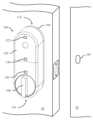
도 1a는 도어(10)와 관련된 도어 잼(12)에 근접하여 개방 도어(10)에 장착된 도어 로크(100)의 일 실시예의 전방 사시도이다. 도어 로크(100)는 무선 트랜시버, 하나 이상의 프로세서, 전원, 액추에이터, 트랜스미션, 구동 샤프트 및/또는 추가적인 내부 구성요소를 둘러싸는 하우징(102)을 포함한다. 도어 로크(100)는 하우징(102)이 관련 도어(10)에 장착되게 하도록 구성된 장착 판(104)을 더 포함한다. 장착 판(104)은 하우징(102)이 하나 이상의 체결구(예를 들어, 나사)를 이용하여 또는 도구 없이(예를 들어, 하나 이상의 래치를 이용하여) 장착되게 할 수 있다. 몇몇 실시예에서, 장착 판은 도어의 기존 데드볼트 로크 하드웨어에 장착될 수 있다. 물론, 하우징(102)을 도어에 장착하기 위해 임의의 적절한 배열이 채용될 수 있는데, 본 개시내용이 그와 같이 제한되지 않기 때문이다.1A is a front perspective view of one embodiment of a
도어 로크(100)는 도어 로크(100)의 구동 샤프트를 대응하게 회전시키기 위해 사용자에 의해 회전될 수 있는 핸들(106)을 더 포함한다. 구동 샤프트는 차례로 데드볼트의 볼트에 결합될 수 있고 구동 샤프트의 회전 운동을 볼트의 선형 운동으로 전달하도록 구성된다. 핸들(106)은, 볼트가 이동할 때마다, 핸들(106)이 대응하게 이동하도록 구동 샤프트에 연속적으로 결합될 수 있다. 물론, 몇몇 실시예에서, 핸들(106)은 도어 로크의 구동 샤프트에 선택적으로 결합 가능할 수 있는데, 본 개시내용이 그와 같이 제한되지 않기 때문이다.The
도어 로크(100)는 제1 자력계(120), 제2 자력계(122), 및 가속도계(130)를 더 포함한다. 제1 자력계(120), 제2 자력계(122), 및 가속도계(130)가 도 1a에서 하우징(102)의 외부 표면에 배치된 것으로 도시되어 있지만, 다른 실시예에서 이들 구성요소 중 임의의 구성요소 또는 전부가 도어 로크(100)의 내부 내에 또는 임의의 다른 적절한 위치에 배치될 수 있음을 이해하여야 하는데, 본 개시내용이 이와 관련하여 제한되지 않기 때문이다. 도어 잼(12)에 자석(150)이 배치된다. 도어(10)가 개방 상태와 폐쇄 상태 사이에서 스윙함에 따라, 자석(150)과 2개의 자력계(120, 122) 사이의 거리가 변경된다. 이론에 구애됨이 없이, 자석과 관련된 자기장의 검출 또는 감지된 세기는 자석으로부터의 거리와 관련될 수 있다. 이와 같이, 자력계는 자기장의 세기를 감지할 수 있기 때문에, 도어 로크(100)의 프로세서는 자력계의 신호로부터 감지된 자기장의 세기를 결정할 수 있고, 그에 따라 자석(150)에 대한 도어 로크(100)의 근접도 및 도어(10)가 개방 또는 폐쇄되어 있는 지의 여부를 결정할 수 있다.The
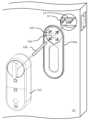
도 1b는 도어 로크 및 도어(10)에 장착된 제1 장착 판(104a)의 일 실시예의 부분 분해 정면 사시도이다. 이 실시예에서, 도어 로크의 하우징(102)(하나 이상의 자력계, 하나 이상의 가속도계, 무선 트랜시버, 하나 이상의 프로세서, 전원, 액추에이터, 트랜스미션, 구동 샤프트 및/또는 추가 구성요소를 포함하고 및/또는 둘러쌈)은 제1 장착판(104a)에 장착되도록 구성된다.1B is a partially exploded front perspective view of one embodiment of the door lock and the
제1 장착판(104a)은 도어(10)에 설치된 데드볼트의 기존 하드웨어에 장착되도록 구성된다. 이 실시예에서, 볼트(도시되지 않음)는 데드볼트 하우징(14) 내에 유지된다. 데드볼트 하우징으로부터 2개의 장착 로드(16)가 연장된다. 제1 장착 판(104a)은 데드볼트의 기존 하드웨어와 맞물림으로써 도어(10)에 장착되도록 구성된다. 이 실시예에서, 장착 로드(16)는 제1 장착 판(104a)의 대응하는 장착 구멍(160)을 통해 연장된다. 제1 장착 판(104a)은 장착 로드(16)가 적어도 4개의 배향 중 임의의 배향으로 복수의 장착 구멍(160) 중 적어도 일부에 의해 수용될 수 있도록 장착 구멍 패턴을 포함한다. 즉, 제1 장착 판(104a)은 데드볼트의 기존 하드웨어에 적어도 4개의 배향 중 임의의 배향으로 장착되도록 구성된다. 하나 이상의 나사형 체결구(나사 또는 볼트를 포함)는 장착 로드(16) 중 하나 이상에 하나 이상의 나사형 체결구를 결합함으로써 판(104a)을 도어(10)에 장착하는 데 사용될 수 있다. 장착 로드(16)는, 예를 들어 바인딩 포스트 배럴 또는 나사형 체결구가 나사 결합될 수 있는 나사형 공동을 포함하는 유사한 하드웨어로서 구체화될 수 있다.The
제1 장착 판(104a)은 구동 샤프트(168)가 통과하도록 구성되는 중앙 보어(166)를 더 포함한다. 구동 샤프트(168)는 (임의로 트랜스미션 및/또는 임의의 적절한 개수의 어댑터를 통해) 도어 로크의 액추에이터의 출력부를 데드볼트의 기존 하드웨어에 결합할 수 있고, 그에 따라 액추에이터와 맞물리면 볼트가 연장 및/또는 후퇴하게 된다. 상이한 어댑터가 액추에이터(또는 트랜스미션)를 데드볼트의 상이한 구동 샤프트에 결합하는 데 사용될 수 있음으로써, 단일 도어 로크가 상이한 데드볼트 설계와 양립 가능하게 할 수 있음을 이해하여야 한다.The
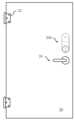
도 1c는 도어 로크 및 도어(10)에 장착된 제2 장착 판(104b)의 일 실시예의 부분 분해 정면 사시도이다. 이 실시예에서, 도어(10)는 도어의 평면을 넘어 돌출하는 로크 실린더(18)를 포함한다. 제2 장착 판(104b)은 로크 실린더(18)를 수용하는 중앙 보어(166)에 의해 돌출 로크 실린더(18)와 정합하도록 구성된다. 제2 장착 판(104b)은 중앙 보어(166)의 주연부 둘레에 복수의 세트 나사 구멍(162)을 포함한다. 세트 나사 구멍(162)은, 설치될 때, 중앙 보어(166)로 연장되는 로크 실린더(18)와 맞물리는 세트 나사를 수용하도록 구성된다. 세트 나사와 로크 실린더(18) 사이의 결과적인 마찰 접촉은 도어(10)에 대한 제2 장착 판(104b)의 위치 및 배향을 고정시킨다. 몇몇 실시예에서, 장착 로드는 제2 장착 판(104b)의 대응하는 장착 구멍으로 추가로 연장될 수 있고, 및/또는 접착제(164)는 제2 장착 판(104b)을 도어(10)에 접착하는 데 사용될 수 있다. 하나의 장착 메커니즘의 사용이 임의의 다른 장착 메커니즘의 사용을 필요로 하거나 암시할 필요가 없기 때문에, 이들 장착 메커니즘 중 임의의 것 또는 전부가 단독으로 또는 조합하여 장착 판을 도어에 장착할 수 있음을 이해하여야 한다.1C is a partially exploded front perspective view of one embodiment of the door lock and the
도 1c의 실시예에서, 하우징(102)(및 둘러싸인 구성요소)이 제2 장착 판(104b)에 장착될 때 키(20)가 로크 실린더(18)에 삽입된다. 이와 같이, 도어 로크의 액추에이터 및/또는 트랜스미션의 출력부는 키(20)와 맞물리도록 구성된 어댑터를 포함할 수 있다. 이러한 어댑터는, 예를 들어 하우징이 키 위에 설치될 때 키가 삽입되는 슬롯 또는 포켓을 포함할 수 있다. 이러한 방식으로, 도어 로크의 액추에이터의 회전은 키(20)를 회전시켜 데드볼트의 볼트를 연장 및/또는 후퇴시킴으로써, 도어를 로킹하거나 로킹 해제할 수 있다.In the embodiment of FIG. 1C , key 20 is inserted into
도 1c의 판(104b)은 또한 몇몇 실시예에서 도어(10)와 접촉하는 판(104b)의 표면 상의 접착제 재료(164)를 포함할 수 있다. 일부 경우에, 로크의 로크 실린더(18)는 도어(10)의 표면과 동일 높이이거나 도어(10)의 표면과 충분히 동일 높이일 수 있어, 신뢰성 있는 장착부를 형성하는 방식으로 세트 나사가 실린더(18)에 고정되는 것을 방해할 수 있다. 그러한 일부 경우에, 세트 나사 및 세트 나사 구멍(162)을 사용하는 대신, 판(104b)이 접착제 재료(164)를 사용하여 도어(10)에 장착될 수 있다. 일부 경우에, 접착제 재료(164)는 왁스 종이 또는 다른 적절한 재료와 같은 임의의 적절한 제거 가능한 재료로 제조된 커버로 덮일 수 있다. 접착제(164)가 장착에 사용되지 않는 경우, 커버가 접착제(164) 상에 유지될 수 있다. 접착제(164)가 사용되는 경우, 커버를 제거함으로써 접착제(164)가 노출될 수 있다.
몇몇 실시예에서, 로크(102)(및 그 구성요소) 뿐만 아니라 판(104a 및 104b) 뿐만 아니라 구동 샤프트 및/또는 키를 구동하기 위한 적절한 어댑터를 포함하는 키트가 제공될 수 있다.In some embodiments, a kit may be provided that includes suitable adapters for driving the lock 102 (and its components) as well as the
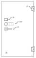
도 2a 내지 도 2d는 상이한 배향으로 도어(20)에 장착된 도어 로크(200)의 정면도이다. 몇몇 실시예에서, 도어 로크는 적어도 4개의 배향 중 임의의 배향으로 장착되도록 구성될 수 있다.2A to 2D are front views of the
도 2a는 제1 배향으로 도어(20)에 장착된 도어 로크(200)를 도시한다. 이 실시예에서, 도어(20)의 도어 핸들(24)은 도어(20)의 데드볼트 바로 아래에 배열된다. 대응하게, 도어 로크(200)는 수직 배향으로 장착되어 도어 로크(200)가 위로 데드볼트로부터 멀어지게 연장되고, 로크(200)는 도어 로크(200)의 액추에이터 및 썸 턴 또는 핸들이 기존 로크 세트의 키 또는 구동 샤프트 위에 장착되도록 도어에 위치된다(위의 도 1b 및 도 1c의 설명 참조). 이 배향에서, 하우징의 주축은 도어의 높이 축과 정렬되고 하우징의 제2 단부는 제1 단부보다 도어의 상단에 더 가깝게 위치된다.2A shows the
도 2b는 제2 배향으로 도어(20)에 장착된 도어 로크(200)를 도시한다. 이 실시예에서, 도어(20)의 도어 핸들(24)은 도어(20)의 데드볼트 바로 위에 배열된다. 대응하게, 도어 로크(200)는 수직 배향으로 장착되어 도어 로크(200)가 아래로 데드볼트로부터 멀어지게 연장되고, 로크(200)는 도어 로크(200)의 액추에이터 및 썸 턴 또는 핸들이 기존 로크 세트의 키 또는 구동 샤프트 위에 장착되도록 도어에 위치된다(위의 도 1b 및 도 1c의 설명 참조). 이 배향에서, 하우징의 주축은 도어의 높이 축과 정렬되고 하우징의 제1 단부는 제2 단부보다 도어의 상단에 더 가깝게 위치된다.2B shows
도 2c는 제3 배향으로 도어(20)에 장착된 도어 로크(200)를 도시한다. 이 실시예에서, 도어(20)의 도어 핸들(24)은 도어(20)의 데드볼트 바로 아래에 배열된다. 추가로, 초인종(26) 또는 다른 도어 장착형 구성요소가 데드볼트 바로 위에 배열된다. 대응하게, 도어 로크(200)는 수평 배향으로 장착되어 도어 로크(200)가 좌측으로 도어의 에지로부터 멀어지게 연장되고, 로크(200)는 도어 로크(200)의 액추에이터 및 썸 턴 또는 핸들이 기존 로크 세트의 키 또는 구동 샤프트 위에 장착되도록 도어에 위치된다(위의 도 1b 및 도 1c의 설명 참조). 이 배향에서, 하우징의 주축은 도어의 폭 축과 정렬되고 제1 단부는 제2 단부의 우측에 위치된다.2C shows
도 2d는 제4 배향으로 도어(20)에 장착된 도어 로크(200)를 도시한다. 이 실시예에서, 도어(20)의 도어 핸들(24)은 도어(20)의 데드볼트 바로 아래에 배열된다. 추가로, 초인종(26) 또는 다른 구성요소가 데드볼트 바로 위에 배열된다. 그러나, 도 2c와 달리, 도 2d의 도어는 반대의 의미를 갖는다. 즉, 도 2c의 도어(20)가 도어의 좌측을 향한 힌지(22) 및 도어의 우측을 향한 핸들(24)을 포함하는 반면, 도 2d의 도어(20)는 도어의 우측을 향한 힌지(22) 및 도어의 좌측을 향한 핸들(24)을 포함한다. 대응하게, 도어 로크(200)는 수평 배향으로 장착되어 도어 로크(200)가 우측으로 도어의 에지로부터 멀어지게 연장되고, 로크(200)는 도어 로크(200)의 액추에이터 및 썸 턴 또는 핸들이 기존 로크 세트의 키 또는 구동 샤프트 위에 장착되도록 도어에 위치된다(위의 도 1b 및 도 1c의 설명 참조). 이 배향에서, 하우징의 주축은 도어의 폭 축과 정렬되고 제1 단부는 제2 단부의 좌측에 위치된다.2D shows the
도어의 핸들에 대한 도어 로크의 위치는 비제한적임을 이해하여야 한다. 예를 들어, 도어 로크는 핸들 위 또는 아래 위치에 수평 좌측 또는 수평 우측 배향으로 장착될 수 있거나, 도어 로크는 핸들 위 또는 아래 위치에 수직 상향 또는 수직 하향 배향으로 장착될 수 있다(물론, 이 방식으로 있는 도어에 다른 도어 구성요소가 장착되어 있지 않다고 가정함). 도어 로크의 배향(예를 들어, 수직 상향, 수직 하향, 수평 좌측, 수평 우측 또는 임의의 다른 배향)은 임의의 다른 도어 구성요소에 대한 도어 로크의 위치(예를 들어, 도어 핸들의 위, 아래, 좌측, 또는 우측)와 관련될 필요는 없다. 또한, 도어 로크는 임의의 의미(즉, 도어 힌지가 우측에 있는 지 또는 좌측에 있는 지의 여부)의 도어의 어느 한 측면에 임의의 배향으로 장착될 수 있음을 이해하여야 하는데, 본 개시내용이 그와 같이 제한되지 않기 때문이다.It should be understood that the position of the door lock relative to the handle of the door is not limiting. For example, the door lock can be mounted in a horizontal left or horizontal right orientation in an above or below handle position, or a door lock can be mounted in a vertical upward or vertical downward orientation in an above or below handle position (of course, (assuming no other door components are fitted to the door with ). The orientation of the door lock (e.g., vertically up, vertically down, horizontal left, horizontal right, or any other orientation) may depend on the position of the door lock relative to any other door component (e.g., above, below the door handle). , left, or right) need not be related. It should also be understood that the door lock may be mounted in any orientation on either side of the door, in any sense (i.e., whether the door hinge is on the right side or on the left side); because it is not limited to
도 3은 본 명세서에 설명된 몇몇 예시적인 실시예에 따른 도어 로크의 설치 방법에 대한 흐름도이다. 블록 302에서, 도어 로크의 원하는 배향이 선택된다. 전술한 바와 같이, 도어 로크의 배향은 다른 도어 구성요소의 위치 및 배향, 사용자 선호도, 또는 기타 요인에 적어도 부분적으로 기초하여 선택될 수 있다. 블록 304에서, 적절한 장착 판이 선택된다. 장착 판의 선택은, 개조될 데드볼트의 스타일 및/또는 설계 또는 도어 핸들과 같은 다른 도어 구성요소의 위치 및 배향을 포함하지만 이에 제한되지 않는 기타 요인에 추가하여, 도어 로크의 선택된 배향에 따라 적어도 부분적으로 달라질 수 있다. 블록 306에서, 선택된 장착 판에 대해 적절한 장착 기술이 선택된다. 전술한 바와 같이, 장착 기술은 기존의 데드볼트 하드웨어와 맞물리는 나사, 로크 실린더와 맞물리는 세트 나사, 데드볼트 또는 도어의 표면에 접착되는 접착제를 포함할 수 있다(단, 이에 제한되지 않음). 블록 308에서, 장착 판이 도어에 장착되며, 이는 장착 판을 도어의 데드볼트에 장착하는 것을 포함할 수 있다. 몇몇 실시예에서, 장착 판은 적어도 4개의 배향 중 하나의 배향으로 도어에 고정될 수 있다.3 is a flowchart of a method for installing a door lock according to some exemplary embodiments described herein. At
블록 310에서, 하우징은 장착 판에 대해 위치 설정된다. 장착 판에 대한 하우징의 위치는 도어 로크의 원하는 배향 뿐만 아니라 장착 판의 배향에 따라 적어도 부분적으로 달라질 수 있다. 몇몇 실시예에서, 하우징을 장착 판에 대해 위치 설정하는 단계는 하우징 내에 배치된 액추에이터 및/또는 트랜스미션을 구동 샤프트 및/또는 도어의 기존 데드볼트의 다른 구성요소와 맞물리게 하는 단계를 포함할 수 있다. 액추에이터는 트랜스미션 및/또는 구동 샤프트를 통해 로킹 위치 및/또는 로킹 해제 위치로 데드볼트의 볼트를 구동하도록 구성될 수 있다. 블록 312에서, 도어 로크의 래치가 폐쇄되어 도어 로크의 하우징을 장착 판에 고정한다. 블록 314에서, 2개(또는 그 이상)의 근접도 센서가 교정된다. 근접도 센서의 교정은 도어를 개방 및 폐쇄하는 것, 및 근접도 센서에 의해 생성된 신호를 기록하는 것을 포함할 수 있다. 예를 들어, 도어가 폐쇄되어 있는 동안, 사용자는 사용자 인터페이스를 통해 도어가 폐쇄되었다는 것을 프로세서에 나타낼 수 있고, 프로세서는 도어가 폐쇄되었다는 것을 나타내는 근접도 센서로부터의 대응 신호를 기록할 수 있다. 도어가 개방될 때 또는 도어가 개방되어 있는 다수의 상이한 상태에서 유사한 절차가 반복될 수 있다. 물론, 근접도 센서는 복수의 상이한 방식 중 임의의 방식으로 교정될 수 있으며, 본 개시내용은 근접도 센서가 교정될 수 있는 방법에 제한되지 않음을 이해하여야 한다.At
몇몇 실시예에서, 도어 로크를 설치하는 것은 사용자 인터페이스를 통해 하우징의 배향을 수동으로 선택하는 것을 더 포함할 수 있다. 이러한 사용자 인터페이스는 몇몇 실시예에서 도어 로크의 하우징과 일체화될 수 있고, 이러한 경우 실시예가 이러한 점에서 제한되지 않기 때문에 임의의 적절한 형태를 취할 수 있다. 예를 들어, 배향을 입력하기 위해 스위치 또는 버튼이 사용될 수 있다. 다른 실시예에서, 사용자 인터페이스는 하우징과 일체화되지 않을 수 있지만, 대신에 다른 디바이스에 위치될 수 있다. 예를 들어, 사용자의 컴퓨팅 디바이스(예를 들어, 스마트폰, 스마트 워치 또는 스마트 글래스와 같은 웨어러블 컴퓨팅 디바이스, 태블릿 컴퓨팅 디바이스, 랩탑 또는 데스크탑 개인용 컴퓨터, 개인 정보 단말기(personal digital assistant)(PDA) 또는 기타 디바이스)는 앱과 같은 소프트웨어를 실행할 수 있으며 소프트웨어를 통해 사용자에게 사용자 인터페이스를 제공할 수 있다. 사용자는 사용자 인터페이스를 조작하여 사용자 인터페이스에 배향을 입력할 수 있다. 그러면, 소프트웨어 및 디바이스는 하우징 내에 배치된 프로세서에 배향을 무선으로 전달할 수 있고, 프로세서는 수신 시 배향 정보를 저장할 수 있다.In some embodiments, installing the door lock may further include manually selecting an orientation of the housing via a user interface. This user interface may in some embodiments be integral with the housing of the door lock, in which case it may take any suitable form as the embodiments are not limited in this respect. For example, a switch or button may be used to enter orientation. In other embodiments, the user interface may not be integrated with the housing, but may instead be located on another device. For example, a user's computing device (eg, a smart phone, a wearable computing device such as a smart watch or smart glasses, a tablet computing device, a laptop or desktop personal computer, a personal digital assistant (PDA), or other device) may run software such as an app and may provide a user interface through the software. A user may manipulate the user interface to input an orientation into the user interface. The software and device can then wirelessly communicate the orientation to a processor disposed within the housing, and the processor can store the orientation information upon receipt.
근접도 센서가 자력계(또는 다른 자기 센서)인 실시예에서, 도어 로크를 설치하는 것은 도어와 관련된 도어 잼에 자석 또는 자성 재료를 고정하는 것을 더 포함할 수 있다. 근접도 센서가 다른 재료 또는 디바이스를 감지하기 위한 다른 센서로서 구체화되는 경우, 설치는 이러한 다른 재료 또는 디바이스를 잼에 고정하는 것을 포함할 수 있다.In embodiments where the proximity sensor is a magnetometer (or other magnetic sensor), installing the door lock may further include securing a magnet or magnetic material to the door jamb associated with the door. If the proximity sensor is embodied as another sensor for sensing other materials or devices, installation may include securing such other materials or devices to jambs.
도 4는 본 명세서에 설명된 몇몇 예시적인 실시예에 따라 도어가 조금 열려 있는 지의 여부를 결정하는 방법에 대한 흐름도이다. 도 4의 방법은 도어 로크의 하나 이상의 저장 장치(예를 들어, 메모리)에 저장되고 도어 로크의 프로세서에 의해 실행되는 실행 가능한 명령을 통해 도어 로크에 의해 구현될 수 있거나, 달리 제어 회로에 의해 구현될 수 있다.4 is a flow diagram of a method for determining whether a door is partially open, according to some exemplary embodiments described herein. The method of FIG. 4 may be implemented by the door lock via executable instructions stored in one or more storage devices (e.g., memory) of the door lock and executed by a processor of the door lock, or otherwise implemented by control circuitry. It can be.
도어의 해당 상태 또는 스테이터스와 관련하여 본 명세서에 사용될 때, 용어 "개방" 및 "조금 열림"은 "폐쇄되지 않음"을 의미하는 동의어로 사용된다는 것을 이해하여야 한다.It should be understood that when used herein with reference to the state or status of a door, the terms "open" and "slightly open" are used synonymously to mean "unclosed."
블록 402에서, 도어 로크는 도어에 장착된 배향을 결정한다. 몇몇 실시예에서, 도어 로크는 도어 로크의 가속도계(또는 다른 센서)의 신호를 분석함으로써 자동으로 배향을 결정할 수 있다. 몇몇 실시예에서, 도어 로크는 수동으로 정보를 입력한 사용자로부터 사용자 인터페이스를 통해 수신된 정보에 따라 배향을 결정할 수 있다. 도어 로크는 도어 로크와 일체화된 사용자 인터페이스 또는 다른 사용자 인터페이스를 포함하는 임의의 적절한 사용자 인터페이스를 통해 정보를 획득할 수 있고, 몇몇 실시예에서는 도어 로크와 별개인 컴퓨팅 디바이스로부터, 예컨대 관련 애플리케이션을 실행하는 사용자의 스마트폰으로부터 무선으로 배향 정보를 수신할 수 있다.At
블록 404에서, 도어 로크는 도어 로크의 복수의 자력계 중 하나를 주 자력계로서 선택한다. 주 자력계는 도어 로크의 결정된 배향에 적어도 부분적으로 기초하여 선택될 수 있다. 예를 들어, 도어 로크는 도어 로크에서 각각의 자력계의 위치에 대한 정보를 갖게 구성될 수 있으며, 도어 로크는 도어가 폐쇄될 때 도어 잼에 가장 가까운 위치에 있는 자력계를 선택할 수 있다. 몇몇 실시예에서, 도어 로크는 로크가 특정 배향에 있을 때 특정 자력계를 주 자력계로서 선택하도록 구성될 수 있다.At
블록 406에서, 선택된 자력계로부터의 신호가 획득된다. 블록 408에서, 도어 로크는 도어 스테이터스(예를 들어, 폐쇄 또는 조금 열림)를 결정하는 부분으로서 자력계 신호를 분석한다. 몇몇 실시예에서, 신호를 분석하기 위해, 도어 로크는 신호를 교정 루틴 동안 생성된 신호와 같은 기준 신호와 비교한다. 이러한 기준 신호는 도어가 폐쇄될 때 자력계 신호의 예상된 값에 대응할 수 있다. 자력계로부터의 신호가 한 번에 기준 신호와 일치하는 경우, 예컨대 기준 신호와 동일하고 및/또는 기준 신호의 임계값 양 내에 있는 경우, 도어가 폐쇄될 수 있다. 그러나, 자력계 신호가 기준 신호와 일치하지 않으면, 도어가 개방될 수 있다. 도어 로크는 이러한 결정을 하기 위해 기준 신호에 관하여 자력계 신호를 분석할 수 있다.At
블록 410에서, 신호의 분석 결과에 적어도 부분적으로 기초하여, 도어가 조금 열려 있는 지의 여부에 대한 결정이 이루어진다. 그 후, 도 4의 프로세스가 종료된다. 프로세스 이후에, 블록 410의 결정은 임의의 적절한 방식으로 사용될 수 있다. 예를 들어, 도어가 개방된/조금 열려 있는 것으로 결정되면, 몇몇 실시예에서 도어가 개방되어 있다는 통지가 사용자에게 전송될 수 있다. 이는 도어가 개방되어 있다는 것을 사용자에게 통지할 수 있는 도어 로크로부터의 통지를 사용자의 컴퓨팅 디바이스 또는 다른 디바이스(예를 들어, 서버)에 직접 무선으로 송신하는 것을 포함할 수 있다. 도 4의 프로세스가 도어 스테이터스에 대한 정보를 요청하는 사용자 또는 다른 엔티티에 의해 개시된 경우, 프로세스 후에, 도어 로크는 요청에 대한 응답을 송신할 수 있으며, 이는 도어의 결정된 스테이터스(예를 들어, 폐쇄 또는 개방/조금 열림)를 나타낸다.At
도 4의 방법은 하나의 자력계로부터 하나의 신호를 사용하는 것과 관련하여 설명되었다. 그러나, 실시예가 그렇게 제한되지 않는다는 것을 이해하여야 한다. 몇몇 실시예에서, 하나의 자력계가 주 자력계로서 취급될 수 있고 주로 도어 스테이터스를 결정하는 데 사용될 수 있는 반면, 다른 실시예에서는 하나 이상의 보조 자력계가 도어 스테이터스를 결정하는 데 추가로 사용될 수 있다. 이러한 몇몇 실시예에서, 주 자력계의 신호를 분석한 결과는 도어 스테이터스를 결정할 때 가장 가중될 수 있는 반면, 보조 자력계(들)로부터의 신호(들)를 분석한 결과(들)는 덜 가중될 수 있다. 다수의 자력계로부터의 신호가 분석되는 실시예에서, 신호는 몇몇 실시예에서 유사한 방식으로 분석될 수 있다. 예를 들어, 분석이 교정과 같은 기준 값과 신호를 비교하는 것을 포함한다면, 각각의 자력계 신호는 대응하는 기준 신호와 각각 비교될 수 있으며, 각각의 신호는 교정 동안 획득되었을 수 있다. 모든 신호가 기준 신호와 일치하여 도어가 폐쇄되어 있다는 것을 나타내면, 도어가 폐쇄되어 있다는 결정이 이루어질 수 있다. 주 자력계의 비교 결과가 도어가 폐쇄되어 있음을 나타내지만 보조 자력계의 비교 결과가 도어가 개방되어 있음을 나타내면, 주 자력계로부터의 비교 결과를 그 결과로서 사용할 수 있다. 또는, 2개의 결과가 상이한 경우, 도어 로크는 도어 스테이터스가 불확실하다고 결정할 수 있거나, 도어가 한 스테이터스에 있을 수 있지만 다른 자력계는 도어가 다른 스테이터스에 있을 수 있음을 나타내는 스테이터스 결정을 출력할 수 있다.The method of Figure 4 has been described in terms of using one signal from one magnetometer. However, it should be understood that the embodiments are not so limited. In some embodiments, one magnetometer may be treated as the primary magnetometer and used primarily to determine door status, while in other embodiments one or more auxiliary magnetometers may be additionally used to determine door status. In some such embodiments, the result(s) of analyzing the signal(s) from the secondary magnetometer(s) may be given the most weight in determining the door status, while the result(s) of analyzing the signal(s) from the secondary magnetometer(s) may be weighted less. there is. In embodiments where signals from multiple magnetometers are analyzed, the signals may be analyzed in a similar manner in some embodiments. For example, if the analysis involves comparing a signal to a reference value, such as a calibration, then each magnetometer signal can each be compared to a corresponding reference signal, each signal acquired during calibration. If all signals match the reference signal to indicate that the door is closed, a determination that the door is closed can be made. If the comparison result of the main magnetometer indicates that the door is closed, but the comparison result of the auxiliary magnetometer indicates that the door is open, then the comparison result from the main magnetometer can be used as the result. Or, if the two results are different, the door lock may determine that the door status is uncertain, or the door may be in one status, but the other magnetometer may output a status determination indicating that the door may be in a different status.
도 4의 방법은 자력계를 참조하여 설명되지만, 개시내용이 그렇게 제한되지 않기 때문에 임의의 적절한 근접도 센서가 사용될 수 있음을 이해하여야 한다.Although the method of FIG. 4 is described with reference to a magnetometer, it should be understood that any suitable proximity sensor may be used as the disclosure is not so limited.
도 5는 본 명세서에 설명된 몇몇 예시적인 실시예에 따른 도어의 스테이터스를 결정하는 다른 방법에 대한 흐름도이다. 도 5의 방법은, 몇몇 실시예에서, 공격자가 외부 자석을 사용하여 도어 로크의 자력계가 잘못된 값을 출력하게 하고 도어 로크가 도어 스테이터스에 대해 잘못된 결론에 도달하게 하도록 시도하는 시나리오에서와 같이, 도어가 공격을 받고 있는 지의 여부를 결정하는 데 사용될 수 있다. 도 4의 방법은 도어 로크의 하나 이상의 저장 장치(예를 들어, 메모리)에 저장되고 도어 로크의 프로세서에 의해 실행되는 실행 가능한 명령을 통해 도어 로크에 의해 구현될 수 있거나, 달리 제어 회로에 의해 구현될 수 있다.5 is a flow chart of another method for determining the status of a door according to some exemplary embodiments described herein. The method of FIG. 5 may, in some embodiments, detect a door lock, such as in a scenario in which an attacker uses an external magnet to cause the door lock's magnetometer to output an incorrect value and attempt to cause the door lock to reach an incorrect conclusion about the door status. can be used to determine whether or not is under attack. The method of FIG. 4 may be implemented by the door lock via executable instructions stored in one or more storage devices (e.g., memory) of the door lock and executed by a processor of the door lock, or otherwise implemented by control circuitry. It can be.
도어의 스테이터스는, 단순히 도어의 스테이터스를 확인하거나, 예컨대 도어를 로킹 해제하는 요청에 응답하여 도어를 로킹 해제할 지의 여부를 결정하는 것을 포함하지만 이에 제한되지 않는 임의의 적절한 이유로 결정될 수 있음을 이해하여야 한다.It should be understood that the status of the door may be determined for any suitable reason, including but not limited to simply checking the status of the door or, for example, determining whether to unlock the door in response to a request to unlock the door. do.
블록 502에서, 도어 로크는 도어 로크의 주 자력계로부터 제1 신호를 수신한다. 전술한 바와 같이, 도어 로크는 전술한 기술을 사용하는 것을 포함하여 도어 로크의 배향에 적어도 부분적으로 기초하여 주 자력계를 선택할 수 있다. 블록 504에서, 도어 로크는 도어 로크의 보조 자력계로부터 제2 신호를 수신한다.At
블록 506에서, 도어 로크는 제1 및 제2 신호를 분석한다. 신호를 분석하는 것은 제1 신호를 제1 기준 신호와 비교하고 제2 신호를 제2 기준 신호와 비교하는 것을 포함할 수 있다. 전술한 바와 같이, 기준 신호는 교정 루틴 동안 생성될 수 있다.At
몇몇 실시예에서, 블록 506에서, 도어 로크는 또한 제1 및 제2 신호가 서로 일치하는 지의 여부를 결정할 수 있다. 예를 들어, 제1 신호가 대응 기준값과 일치하고 제2 신호가 일치하지 않는 경우(또는 그 반대도 마찬가지임), 도어 로크는 2개의 신호가 서로 일치하지 않는 것으로 결정할 수 있다. 다른 예로서, 몇몇 실시예에서, 도어 로크는 제1 기준 신호의 주어진 값에 대해, 제2 신호의 값이 제2 신호의 예상 값과 일치하는 지의 여부를 결정할 수 있다. 이는, 일반적인 상황에서(즉, 공격 중이 아닌 경우), 2개의 자력계가 예측 가능한 방식으로, 그리고 예측 가능하게 변경되는 방식으로 신호를 출력할 수 있기 때문에 수행될 수 있다. 이는, 힌지 결합된 도어의 경우, 자력계가 잼에 배치된 자석으로부터 더 멀어지게 또는 더 가깝게 이동함에 따라, 자력계가 도어의 스윙 경로를 따라 변경되는 신호를 출력할 수 있고, 도어가 스윙될 때마다 동일한 신호(또는 공차의 임계값 차이 이내의 신호)를 출력할 수 있기 때문이다. 양쪽 자력계에 대해 예측 가능한 값이 있을 수 있다고 고려하면, 하나의 자력계에 의해 출력되는 값은 스윙 경로를 따라 도어의 특정 위치에 대응할 수 있으며 해당 도어 위치에서 다른 자력계에 의해 출력되는 값이 결정 가능할 수 있다. 이와 같이, 도어 로크는, 자력계에 대한 블록 502에서 획득된 주어진 값에 대해, 다른 자력계에 대한 신호 값이 해당 자력계에 대한 예상/예측 값과 일치하는 지의 여부를 결정할 수 있다.In some embodiments, at
다른 예로서, 도어 로크는 자력계에서 출력되는 제1 및 제2 신호 값의 최근 변화가 일치되었는 지의 여부를 결정할 수 있다. 예를 들어, 제2 신호가 일정하게 유지되는 동안 크게 변경되는 제1 신호는, 동일한 도어에 모두 장착되어 함께 변경되거나 일정하게 유지되어야 하는 자력계에 의해 출력되는 신호와 일치하지 않을 수 있으며 공격을 나타낼 수 있다.As another example, the door lock may determine whether recent changes in values of the first and second signals output from the magnetometer coincide. For example, a first signal that varies greatly while a second signal remains constant may not match the signal output by a magnetometer that is all mounted on the same door and must either change together or remain constant and indicate an attack. can
블록 508에서, 도어 로크는 블록 506에서 제1 신호 및 제2 신호의 분석 결과에 기초하여 도어의 스테이터스를 결정한다. 몇몇 실시예에서, 도어의 스테이터스를 결정하는 것은 제1 신호 및 제2 신호가 도어가 조금 열려 있거나 폐쇄되어 있음을 나타내는 것으로 결정하는 것을 포함할 수 있다. 몇몇 실시예에서, 도어 로크는 또한 일부 경우에 신호가 예상치 못한 상태를 나타내는 것으로 결정할 수 있다. 이는 도어 스테이터스가 불확실하거나 예상치 못한 것임을 나타내는 자력계 신호의 예상치 못한 상태일 수 있다.In
예상치 못한 상태는 일부 경우에 공격(예를 들어, 진행 중인 침입 시도)을 나타내거나, 다른 경우에 오류를 나타낼 수 있다. 몇몇 실시예에서, 예상치 못한 상태를 검출하는 것은 제1 및 제2 신호가 모두 동일한 도어 스테이터스를 나타내지 않거나 서로 불일치한다고 결정하는 것을 포함할 수 있다. 물론, 예상치 못한 상태는 다른 방식으로 제1 신호 및 제2 신호에 기초하여 검출될 수 있으며, 예상된 상태가 검출되는 방법에 관하여 본 개시내용이 제한되지 않는다는 것을 이해하여야 한다.An unexpected state may indicate an attack (eg, an intrusion attempt in progress) in some cases, or an error in other cases. In some embodiments, detecting the unexpected condition may include determining that the first and second signals do not both indicate the same door status or are inconsistent with each other. Of course, it should be understood that the unexpected condition may be detected based on the first signal and the second signal in other ways, and the present disclosure is not limited as to how the expected condition is detected.
블록 510에서, 도어 로크는 도어의 스테이터스를 출력한다. 도어의 스테이터스를 출력하는 것은, (공격을 나타낼 수 있는) 예상치 못한 상태가 결정되는 경우, 도어 로크로부터 도어 로크의 소유자 또는 법 집행 기관과 같이 도어 로크 외부의 수신자에게 무선으로 경보를 보내는 것을 포함할 수 있다. 이와 같이, 이들 실시예에서, 가능한 공격이 검출되면, 로크의 소유자 및/또는 법 집행 기관에 통지될 수 있다. 그러나, 다른 실시예에서는, 가능한 상태를 검출하는 대신에, 도어 로크 오류가 검출될 수 있으며, 법 집행 기관이 아닌 로크의 소유자에게만 통지될 수 있다.At
몇몇 실시예에서, 방법은 또한 도어에 대한 가능한 공격의 검출에 응답하여 도어 로크의 로킹 해제를 억제하도록 도어 로크를 구성하는 단계를 포함할 수 있다. 전술한 바와 같이, 도어에 대한 일부 성공적인 공격으로 인해 도어 로크가 자동으로 로킹 해제될 수 있다. 따라서, 몇몇 실시예에서, 도어 로크는 집주인 또는 로크의 다른 유효한 사용자로부터 수신된 것으로 주장되는 로킹 해제 요청에 응답하더라도 일정 시간 동안 로킹 해제되지 않을 수 있다. 이는 도어 로크가 도어에 침입하려는 시도가 진행 중인 것을 검출한 시나리오에서 도어의 개방을 방지할 수 있다. 이러한 몇몇 실시예에서, 도어 로크는 구성될 수 있는 특정 시간 기간 동안만 로킹 해제를 억제할 수 있다. 예를 들어, 적절한 시간 기간은 5분, 10분, 1시간 또는 다른 적절한 시간 기간일 수 있다.In some embodiments, the method may also include configuring the door lock to inhibit unlocking of the door lock in response to detection of a possible attack on the door. As discussed above, some successful attacks on the door may automatically unlock the door lock. Thus, in some embodiments, the door lock may not unlock for a period of time even in response to an unlock request allegedly received from the landlord or other valid user of the lock. This may prevent opening of the door in a scenario where the door lock detects an ongoing attempt to break into the door. In some such embodiments, the door lock may inhibit unlocking only for a specific configurable time period. For example, a suitable time period may be 5 minutes, 10 minutes, 1 hour or other suitable time period.
본 명세서에 설명된 기술의 전술한 실시예는 임의의 많은 방식으로 구현될 수 있다. 예를 들어, 실시예는 하드웨어, 소프트웨어 또는 이들의 조합을 사용하여 구현될 수 있다. 소프트웨어로 구현될 때, 소프트웨어 코드는 단일 컴퓨터에서 제공되든 다수의 컴퓨터에 분산되든 간에 임의의 적절한 프로세서 또는 프로세서 집합체에서 실행될 수 있다. 이러한 프로세서는 CPU 칩, GPU 칩, 마이크로프로세서, 마이크로제어기, 또는 코프로세서와 같은 명칭으로 본 기술 분야에 알려진 상업적으로 이용 가능한 집적 회로 구성요소를 포함하는 집적 회로 구성요소에 하나 이상의 프로세서가 있는 집적 회로로서 구현될 수 있다. 대안적으로, 프로세서는 ASIC와 같은 주문형 회로 또는 프로그래밍 가능한 로직 디바이스를 구성하는 것에 기인한 반주문형 회로로 구현될 수 있다. 또 다른 대안으로서, 프로세서는 상업적으로 이용 가능하든, 반주문형이든, 주문형이든 더 큰 회로 또는 반도체 디바이스의 일부일 수 있다. 특정 예로서, 일부 상업적으로 이용 가능한 마이크로프로세서는 다중 코어를 가질 수 있고, 그에 따라 이들 코어 중 하나 또는 서브세트가 프로세서를 구성할 수 있다. 그러나, 프로세서는 임의의 적절한 형식의 회로를 사용하여 구현될 수 있다.The foregoing embodiments of the technology described herein may be implemented in any number of ways. For example, an embodiment may be implemented using hardware, software, or a combination thereof. When implemented in software, the software code may execute on any suitable processor or collection of processors, whether provided on a single computer or distributed among multiple computers. Such processors may include commercially available integrated circuit components known in the art under names such as CPU chips, GPU chips, microprocessors, microcontrollers, or coprocessors. Integrated circuits having one or more processors in integrated circuit components. can be implemented as Alternatively, the processor may be implemented with custom circuitry such as an ASIC or semi-custom circuitry resulting from constructing a programmable logic device. As another alternative, the processor may be part of a larger circuit or semiconductor device, whether commercially available, semi-custom, or custom. As a specific example, some commercially available microprocessors may have multiple cores, such that one or a subset of these cores may constitute a processor. However, a processor may be implemented using any suitable type of circuitry.
이러한 프로세서는 근거리 네트워크 또는 광역 네트워크, 예컨대 엔터프라이즈 네트워크 또는 인터넷을 비롯하여, 임의의 적절한 형태의 하나 이상의 네트워크에 의해 상호 연결될 수 있다. 그러한 네트워크는 임의의 적절한 기술에 기초할 수 있고 임의의 적절한 프로토콜에 따라 작동할 수 있으며 무선 네트워크, 유선 네트워크, 또는 광섬유 네트워크를 포함할 수 있다.Such processors may be interconnected by one or more networks of any suitable type, including a local area network or a wide area network, such as an enterprise network or the Internet. Such networks may be based on any suitable technology and operate according to any suitable protocol, and may include wireless networks, wired networks, or fiber optic networks.
또한, 본 명세서에 개설된 다양한 방법 또는 프로세스는 다양한 운영 체제 또는 플랫폼 중 임의의 하나를 사용하는 하나 이상의 프로세서에서 실행 가능한 소프트웨어로서 코딩될 수 있다. 추가로, 그러한 소프트웨어는 다수의 적절한 프로그래밍 언어 및/또는 프로그래밍 또는 스크립팅 도구 중 임의의 것을 사용하여 기입될 수 있으며, 또한 실행 가능한 기계 언어 코드 또는 프레임워크 또는 가상 기계에서 실행되는 중간 코드로서 컴파일될 수 있다.Additionally, various methods or processes outlined herein may be coded as software executable on one or more processors using any one of a variety of operating systems or platforms. Additionally, such software may be written using any of a number of suitable programming languages and/or programming or scripting tools, and may also be compiled as executable machine language code or framework or intermediate code that runs in a virtual machine. there is.
이와 관련하여, 본 명세서에서 설명되는 실시예는, 하나 이상의 컴퓨터 또는 다른 프로세서에서 실행될 때, 전술한 다양한 실시예를 구현하는 방법을 수행하는 하나 이상의 프로그램으로 인코딩된 컴퓨터 판독 가능 저장 매체(또는 다중 컴퓨터 판독 가능 매체)(예를 들어, 컴퓨터 메모리, 하나 이상의 플로피 디스크, 콤팩트 디스크(compact disc)(CD), 광학 디스크, 디지털 비디오 디스크(digital video disk)(DVD), 자기 테이프, 플래시 메모리, 필드 프로그램 가능 게이트 어레이 또는 기타 반도체 디바이스의 회로 구성, 또는 기타 유형의 컴퓨터 저장 매체)로서 구체화될 수 있다. 전술한 예로부터 명백한 바와 같이, 컴퓨터 판독 가능 저장 매체는 컴퓨터 실행 가능 명령어를 비일시적 형태로 제공하기에 충분한 시간 동안 정보를 유지할 수 있다. 이러한 컴퓨터 판독 가능 저장 매체 또는 매체들은, 저장된 프로그램 또는 프로그램들이 전술한 바와 같이 본 개시내용의 다양한 양태를 구현하기 위해 하나 이상의 상이한 컴퓨터 또는 다른 프로세서 상에 로딩될 수 있도록 수송 가능할 수 있다. 본 명세서에 사용될 때, "컴퓨터 판독 가능 저장 매체"라는 용어는 제조품(즉, 제조 물품) 또는 기계인 것으로 고려될 수 있는 비일시적 컴퓨터 판독 가능 매체만을 포함한다. 대안적으로 또는 추가로, 본 개시내용 전파 신호와 같은 컴퓨터 판독 가능 저장 매체 이외의 컴퓨터 판독 가능 매체로서 구체화될 수 있다.In this regard, the embodiments described herein are computer readable storage media (or multiple computers) encoded with one or more programs that, when executed on one or more computers or other processors, perform methods for implementing the various embodiments described above. readable media) (e.g., computer memory, one or more floppy disks, compact discs (CDs), optical disks, digital video disks (DVDs), magnetic tapes, flash memory, field programs circuit configurations of capable gate arrays or other semiconductor devices, or other tangible computer storage media). As is evident from the foregoing examples, a computer readable storage medium can retain information for a period of time sufficient to provide computer executable instructions in a non-transitory form. Such computer-readable storage medium or media may be transportable such that the stored program or programs may be loaded onto one or more different computers or other processors to implement various aspects of the present disclosure, as described above. As used herein, the term "computer readable storage medium" includes only non-transitory computer readable media that may be considered articles of manufacture (ie, articles of manufacture) or machines. Alternatively or additionally, the present disclosure may be embodied as a computer readable medium other than a computer readable storage medium such as a propagated signal.
"프로그램" 또는 "소프트웨어"라는 용어는 전술한 바와 같이 본 개시내용의 다양한 양태를 구현하기 위해 컴퓨터 또는 다른 프로세서를 프로그래밍하는 데 채용될 수 있는 임의의 유형의 컴퓨터 코드 또는 컴퓨터 실행 가능 명령어 세트를 지칭하도록 일반적인 의미로 본 명세서에 사용된다. 추가로, 이 실시예의 일 양태에 따르면, 실행될 때 본 개시내용의 방법을 수행하는 하나 이상의 컴퓨터 프로그램은 단일 컴퓨터 또는 프로세서에 상주할 필요가 없고, 본 개시내용의 다양한 양태를 구현하기 위한 다수의 여러 컴퓨터 또는 프로세서 중에 모듈형 방식으로 분산될 수 있음을 이해하여야 한다.The term "program" or "software" refers to any type of computer code or set of computer-executable instructions that may be employed to program a computer or other processor to implement various aspects of the present disclosure, as described above. It is used herein in a general sense so as to. Additionally, according to one aspect of this embodiment, one or more computer programs that, when executed, perform the methods of the present disclosure need not reside on a single computer or processor, but can be used to implement multiple different aspects of the present disclosure. It should be understood that it may be distributed in a modular fashion among computers or processors.
컴퓨터 실행 가능 명령어는 하나 이상의 컴퓨터 또는 기타 디바이스에 의해 실행되는 프로그램 모듈과 같은 많은 형태일 수 있다. 일반적으로, 프로그램 모듈은 특정 작업을 수행하거나 특정 추상 데이터 유형을 구현하는 루틴, 프로그램, 개체, 구성요소, 데이터 구조 등을 포함한다. 통상적으로, 프로그램 모듈의 기능은 다양한 실시예에서 원하는 대로 조합되거나 분산될 수 있다.Computer-executable instructions can take many forms, such as program modules executed by one or more computers or other devices. Generally, program modules include routines, programs, objects, components, data structures, etc. that perform particular tasks or implement particular abstract data types. Typically, the functionality of the program modules may be combined or distributed as desired in various embodiments.
또한, 데이터 구조는 임의의 적절한 형태로 컴퓨터 판독 가능 매체에 저장될 수 있다. 예시의 단순화를 위해, 데이터 구조는 데이터 구조의 위치를 통해 관련된 필드를 갖는 것으로 나타낼 수 있다. 이러한 관계는 마찬가지로 필드 사이의 관계를 전달하는 컴퓨터 판독 가능 매체의 위치로 필드에 대한 저장 장치를 할당함으로써 달성될 수 있다. 그러나, 데이터 요소 사이의 관계를 설정하는 포인터, 태그 또는 기타 메커니즘을 사용하는 것을 포함하여 데이터 구조의 필드에 있는 정보 사이의 관계를 설정하기 위해 임의의 적절한 메커니즘이 사용될 수 있다.Also, a data structure may be stored on a computer readable medium in any suitable form. For simplicity of illustration, data structures may be represented as having fields that are related through location in the data structure. Such relationships can be achieved by assigning storage for the fields to a location on a computer readable medium that likewise conveys the relationship between the fields. However, any suitable mechanism may be used to establish relationships between information in fields of a data structure, including using pointers, tags, or other mechanisms to establish relationships between data elements.
본 개시내용의 다양한 양태는 단독으로, 조합하여, 또는 전술한 실시예에서 구체적으로 설명되지 않은 다양한 배열로 사용될 수 있으며, 따라서 전술한 설명에 기재되거나 도면에 예시된 구성요소의 세부 사항 및 배열에 대한 그 적용에 제한되지 않는다. 예를 들어, 일 실시예에서 설명된 양태는 다른 실시예에서 설명된 양태와 임의의 방식으로 조합될 수 있다.The various aspects of the present disclosure may be used alone, in combination, or in various arrangements not specifically described in the foregoing embodiments, and thus do not rely on the details and arrangements of components described in the foregoing description or illustrated in the drawings. Its application is not limited to For example, aspects described in one embodiment may be combined in any manner with aspects described in another embodiment.
또한, 본 명세서에서 설명하는 실시예는 방법으로서 구체화될 수 있으며, 그 예는 제시되었다. 방법의 일부로 수행되는 동작은 임의의 적절한 방식으로 정렬될 수 있다. 따라서, 예시적인 실시예에서 순차적인 동작으로 도시되었더라도, 일부 동작을 동시에 수행하는 것을 포함할 수 있는, 예시된 것과 상이한 순서로 동작이 수행되는 실시예가 구성될 수 있다.In addition, the embodiments described herein may be embodied as a method, examples of which have been presented. The actions performed as part of the method may be ordered in any suitable way. Thus, although shown as sequential operations in exemplary embodiments, embodiments may be constructed in which operations are performed in a different order than illustrated, which may include performing some operations concurrently.
또한, 일부 동작은 "사용자"가 수행한 것으로 설명된다. "사용자"는 한 개인일 필요는 없으며, 몇몇 실시예에서 "사용자"에 기인한 동작은 컴퓨터 지원 도구 또는 다른 메커니즘과 조합하여 개인들의 팀 및/또는 개인에 의해 수행될 수 있음을 이해하여야 한다.Also, some actions are described as being performed by a “user”. It should be understood that a "user" need not be a single individual, and that in some embodiments actions attributed to a "user" may be performed by a team of individuals and/or individuals in combination with computer assisted tools or other mechanisms.
본 교시가 다양한 실시예 및 예와 관련하여 설명되었지만, 본 교시가 그러한 실시예 또는 예로 제한되는 것으로 의도되지는 않는다. 반대로, 본 교시는, 본 기술 분야의 숙련자가 이해할 수 있는 바와 같이, 다양한 대안, 수정 및 등가물을 포함한다. 따라서, 전술한 설명 및 도면은 예시를 위한 것일 뿐이다.Although the present teachings have been described with respect to various embodiments and examples, it is not intended that the present teachings be limited to those embodiments or examples. To the contrary, the present teachings cover various alternatives, modifications and equivalents, as will be understood by those skilled in the art. Accordingly, the foregoing description and drawings are for illustrative purposes only.
Claims (38)
Translated fromKorean도어의 도어 로크 내에 배치된 제1 자력계로부터 제1 신호를 수신하는 단계;
도어의 도어 로크 내에 배치된 제2 자력계로부터 제2 신호를 수신하는 단계; 및
제1 신호 및 제2 신호 모두의 평가 결과에 기초하여, 도어에 대한 가능한 공격을 검출하는 단계를 포함하는, 방법.A method for determining the status of a door,
receiving a first signal from a first magnetometer disposed within a door lock of a door;
receiving a second signal from a second magnetometer disposed within the door lock of the door; and
based on the evaluation results of both the first signal and the second signal, detecting a possible attack on the door.
제1 신호를 제1 기준 신호와 비교하고 제2 신호를 제2 기준 신호와 비교하는 단계; 및
제1 및 제2 신호와 제1 및 제2 기준 신호의 비교에 응답하여, 도어에 대한 가능한 공격을 검출하는 단계를 포함하는, 방법.The method of claim 1 , wherein based on the evaluation results of both the first signal and the second signal, detecting a possible attack on the door comprises:
comparing a first signal with a first reference signal and comparing a second signal with a second reference signal; and
responsive to comparing the first and second signals with the first and second reference signals, detecting a possible attack on the door.
도어에 대한 가능한 공격의 검출에 응답하여 도어 로크의 소유자에게 경보를 전송하는 단계를 더 포함하는, 방법.According to claim 1 or 2,
responsive to detection of a possible attack on the door, sending an alert to the owner of the door lock.
도어에 대한 가능한 공격의 검출에 응답하여 법 집행 기관에 경보를 전송하는 단계를 더 포함하는, 방법.According to any one of claims 1 to 3,
Sending an alert to a law enforcement agency in response to detection of a possible attack on the door.
도어에 대한 가능한 공격의 식별에 응답하여 도어 로크의 로킹 해제를 억제하는 단계를 더 포함하는, 방법.According to any one of claims 1 to 4,
inhibiting unlocking of the door lock in response to the identification of a possible attack on the door.
제1 및 제2 신호가 일치하는 지의 여부를 결정하는 단계; 및
제1 신호와 제2 신호가 일치하지 않는다는 결정에 응답하여, 도어에 대한 가능한 공격을 검출하는 단계를 포함하는, 방법.7. The method according to any one of claims 1 to 6, wherein based on the evaluation result of both the first signal and the second signal, detecting a possible attack on the door comprises:
determining whether the first and second signals coincide; and
responsive to determining that the first and second signals do not match, detecting a possible attack on the door.
도어의 도어 로크 내에 배치된 제1 자력계로부터 제1 신호를 수신하는 단계;
도어의 도어 로크 내에 배치된 제2 자력계로부터 제2 신호를 수신하는 단계; 및
제1 신호 및 제2 신호 모두의 평가 결과에 기초하여, 도어에 대한 가능한 공격을 검출하는 단계를 포함하는, 컴퓨터 판독 가능 저장 매체.At least one non-transitory computer-readable storage medium encoded with executable instructions that, when executed, cause at least one processor to perform a method of determining the status of a door, the method comprising:
receiving a first signal from a first magnetometer disposed within a door lock of a door;
receiving a second signal from a second magnetometer disposed within the door lock of the door; and
Based on the evaluation result of both the first signal and the second signal, detecting a possible attack on the door.
제1 신호를 제1 기준 신호와 비교하고 제2 신호를 제2 기준 신호와 비교하는 단계; 및
제1 및 제2 신호와 제1 및 제2 기준 신호의 비교에 응답하여, 도어에 대한 가능한 공격을 검출하는 단계를 포함하는, 컴퓨터 판독 가능 저장 매체.9. The method of claim 8, wherein based on the evaluation results of both the first signal and the second signal, detecting a possible attack on the door comprises:
comparing a first signal with a first reference signal and comparing a second signal with a second reference signal; and
responsive to comparing the first and second signals with the first and second reference signals, detecting a possible attack on the door.
도어에 대한 가능한 공격의 검출에 응답하여 도어 로크의 소유자에게 경보를 전송하는 단계를 더 포함하는, 컴퓨터 판독 가능 저장 매체.10. The method of claim 8 or 9, wherein the method:
responsive to detecting a possible attack on the door, sending an alert to the owner of the door lock.
도어에 대한 가능한 공격의 검출에 응답하여 법 집행 기관에 경보를 전송하는 단계를 더 포함하는, 컴퓨터 판독 가능 저장 매체.11. The method according to any one of claims 8 to 10, wherein the method:
Sending an alert to a law enforcement agency in response to detection of a possible attack on the door.
도어에 대한 가능한 공격의 식별에 응답하여 도어 로크의 로킹 해제를 억제하는 단계를 더 포함하는, 컴퓨터 판독 가능 저장 매체.12. The method according to any one of claims 8 to 11, wherein the method:
inhibiting unlocking of the door lock in response to identification of a possible attack on the door.
제1 및 제2 신호가 일치하는 지의 여부를 결정하는 단계; 및
제1 신호와 제2 신호가 일치하지 않는다는 결정에 응답하여, 도어에 대한 가능한 공격을 검출하는 단계를 포함하는, 컴퓨터 판독 가능 저장 매체.14. The method according to any one of claims 8 to 13, wherein based on the evaluation result of both the first signal and the second signal, detecting a possible attack on the door comprises:
determining whether the first and second signals coincide; and
responsive to determining that the first and second signals do not match, detecting a possible attack on the door.
도어의 도어 로크의 볼트를 로킹 위치 및/또는 로킹 해제 위치로 구동하기 위한 액추에이터;
도어에 장착되도록 구성된 하우징으로서, 액추에이터는 하우징 내에 적어도 부분적으로 배치되는, 하우징;
하우징 내에 적어도 부분적으로 배치된 제1 자력계;
하우징 내에 적어도 부분적으로 배치된 제2 자력계;
하우징 내에 배치된 적어도 하나의 프로세서; 및
하우징 내에 배치되고, 실행될 때, 적어도 하나의 프로세서가 방법을 수행하게 하는 실행 가능한 명령이 인코딩된 적어도 하나의 저장 매체를 포함하고, 상기 방법은:
제1 자력계로부터 제1 신호를 수신하는 단계;
제2 자력계로부터 제2 신호를 수신하는 단계; 및
제1 및 제2 신호 및 하나 이상의 기준 신호에 적어도 부분적으로 기초하여 예상치 못한 센서 상태를 검출하는 단계를 포함하는, 장치.is a device,
an actuator for driving a bolt of a door lock of a door to a locked position and/or an unlocked position;
a housing configured to be mounted to a door, wherein the actuator is at least partially disposed within the housing;
a first magnetometer disposed at least partially within the housing;
a second magnetometer disposed at least partially within the housing;
at least one processor disposed within the housing; and
and at least one storage medium disposed within the housing and having encoded thereon executable instructions which, when executed, cause at least one processor to perform a method, the method comprising:
receiving a first signal from a first magnetometer;
receiving a second signal from a second magnetometer; and
An apparatus comprising: detecting an unexpected sensor condition based at least in part on the first and second signals and one or more reference signals.
하우징과 별개인 컴퓨팅 디바이스를 더 포함하고, 컴퓨팅 디바이스는 적어도 하나의 무선 통신 회로를 포함하며, 컴퓨팅 디바이스는 도어의 스테이터스와 관련된 정보를 무선으로 송신하도록 구성되는, 장치.According to claim 15,
11. The apparatus of claim 1, further comprising a computing device separate from the housing, wherein the computing device includes at least one wireless communication circuit, wherein the computing device is configured to wirelessly transmit information related to a status of the door.
제15항의 장치; 및
도어와 관련된 도어 잼에 장착되도록 구성된 자석을 포함하고,
제1 및 제2 센서 각각은 자석을 감지하도록 구성되는, 키트.is a kit,
the apparatus of claim 15; and
a magnet configured to be mounted to a door jamb associated with the door;
wherein each of the first and second sensors is configured to sense a magnet.
도어 로크 내에 배치된 제1 자력계로부터 제1 신호를 수신하는 단계;
도어 로크 내에 배치된 제2 자력계로부터 제2 신호를 수신하는 단계; 및
제1 신호 및 제2 신호 모두의 평가에 기초하여 도어의 스테이터스를 결정하는 단계를 포함하는, 방법.A method for determining the status of a door,
receiving a first signal from a first magnetometer disposed within the door lock;
receiving a second signal from a second magnetometer disposed within the door lock; and
determining the status of the door based on the evaluation of both the first signal and the second signal.
제1 신호를 제1 기준 신호와 비교하고 제2 신호를 제2 기준 신호와 비교하는 단계; 및
제1 및 제2 신호를 제1 및 제2 기준 신호와 비교하는 것에 적어도 부분적으로 기초하여 제1 및 제2 신호가 예상치 못한 상태를 나타내는 지를 결정하는 단계를 포함하는, 방법.20. The method of claim 19, wherein determining whether the first signal and the second signal represent an unexpected condition comprises:
comparing a first signal with a first reference signal and comparing a second signal with a second reference signal; and
and determining whether the first and second signals represent an unexpected condition based at least in part on comparing the first and second signals to the first and second reference signals.
도어의 스테이터스에 적어도 부분적으로 기초하여 도어에 대한 가능한 공격을 검출하는 단계를 더 포함하는, 방법.The method of any one of claims 18 to 22,
The method further includes detecting a possible attack on the door based at least in part on the status of the door.
도어에 대한 가능한 공격의 검출에 응답하여 도어 로크의 소유자에게 경보를 전송하는 단계를 더 포함하는, 방법.According to claim 23,
responsive to detection of a possible attack on the door, sending an alert to the owner of the door lock.
도어의 스테이터스에 적어도 부분적으로 기초하여 도어 로크 오류를 검출하는 단계를 더 포함하는, 방법.The method of any one of claims 18 to 24,
and detecting a door lock failure based at least in part on the status of the door.
도어 로크 오류의 검출에 응답하여 도어 로크의 소유자에게 경보를 전송하는 단계를 더 포함하는, 방법.According to claim 25,
responsive to detecting a door lock failure, sending an alert to the owner of the door lock.
도어 로크 내에 배치된 제1 자력계로부터 제1 신호를 수신하는 단계;
도어 로크 내에 배치된 제2 자력계로부터 제2 신호를 수신하는 단계; 및
제1 신호 및 제2 신호 모두의 평가에 기초하여 도어의 스테이터스를 결정하는 단계를 포함하는, 컴퓨터 판독 가능 저장 매체.At least one non-transitory computer-readable storage medium encoded with executable instructions that, when executed, cause at least one processor to perform a method of determining the status of a door, the method comprising:
receiving a first signal from a first magnetometer disposed within the door lock;
receiving a second signal from a second magnetometer disposed within the door lock; and
A computer readable storage medium comprising: determining a status of a door based on evaluation of both the first signal and the second signal.
제1 신호를 제1 기준 신호와 비교하고 제2 신호를 제2 기준 신호와 비교하는 단계; 및
제1 및 제2 신호를 제1 및 제2 기준 신호와 비교하는 것에 적어도 부분적으로 기초하여 제1 및 제2 신호가 예상치 못한 상태를 나타내는 지를 결정하는 단계를 포함하는, 컴퓨터 판독 가능 저장 매체.29. The method of claim 28, wherein determining whether the first signal and the second signal represent an unexpected condition comprises:
comparing a first signal with a first reference signal and comparing a second signal with a second reference signal; and
A computer-readable storage medium comprising: determining whether the first and second signals represent an unexpected condition based at least in part on comparing the first and second signals to the first and second reference signals.
도어의 스테이터스에 적어도 부분적으로 기초하여 도어에 대한 가능한 공격을 검출하는 단계를 더 포함하는, 컴퓨터 판독 가능 저장 매체.32. The method according to any one of claims 27 to 31, wherein the method:
A computer-readable storage medium further comprising detecting a possible attack on the door based at least in part on the status of the door.
도어에 대한 가능한 공격의 검출에 응답하여 도어 로크의 소유자에게 경보를 전송하는 단계를 더 포함하는, 컴퓨터 판독 가능 저장 매체.33. The method of claim 32, wherein the method:
responsive to detecting a possible attack on the door, sending an alert to the owner of the door lock.
도어의 스테이터스에 적어도 부분적으로 기초하여 도어 로크 오류를 검출하는 단계를 더 포함하는, 컴퓨터 판독 가능 저장 매체.34. The method according to any one of claims 27 to 33, wherein the method:
A computer readable storage medium further comprising detecting a door lock failure based at least in part on the status of the door.
도어 로크 오류의 검출에 응답하여 도어 로크의 소유자에게 경보를 전송하는 단계를 더 포함하는, 컴퓨터 판독 가능 저장 매체.35. The method of claim 34, wherein the method:
responsive to detecting a door lock failure, sending an alert to the owner of the door lock.
도어의 도어 로크의 볼트를 로킹 위치 및/또는 로킹 해제 위치로 구동하기 위한 액추에이터;
도어에 장착되도록 구성된 하우징으로서, 액추에이터는 하우징 내에 적어도 부분적으로 배치되는, 하우징;
하우징 내에 적어도 부분적으로 배치된 제1 자력계;
하우징 내에 적어도 부분적으로 배치된 제2 자력계;
하우징 내에 배치된 적어도 하나의 프로세서; 및
하우징 내에 배치되고, 실행될 때, 적어도 하나의 프로세서가 방법을 수행하게 하는 실행 가능한 명령이 인코딩된 적어도 하나의 저장 매체를 포함하고, 상기 방법은:
제1 자력계로부터 제1 신호를 수신하는 단계;
제2 자력계로부터 제2 신호를 수신하는 단계; 및
제1 및 제2 신호 및 하나 이상의 기준 신호에 적어도 부분적으로 기초하여 도어의 스테이터스를 결정하는 단계를 포함하는, 장치.is a device,
an actuator for driving a bolt of a door lock of a door to a locked position and/or an unlocked position;
a housing configured to be mounted to a door, wherein the actuator is at least partially disposed within the housing;
a first magnetometer disposed at least partially within the housing;
a second magnetometer disposed at least partially within the housing;
at least one processor disposed within the housing; and
and at least one storage medium disposed within the housing and having encoded thereon executable instructions which, when executed, cause at least one processor to perform a method, the method comprising:
receiving a first signal from a first magnetometer;
receiving a second signal from a second magnetometer; and
determining a status of a door based at least in part on the first and second signals and the one or more reference signals.
하우징과 별개인 컴퓨팅 디바이스를 더 포함하고, 컴퓨팅 디바이스는 적어도 하나의 무선 통신 회로를 포함하며, 컴퓨팅 디바이스는 도어의 스테이터스와 관련된 정보를 무선으로 송신하도록 구성되는, 장치.37. The method of claim 36,
11. The apparatus of claim 1, further comprising a computing device separate from the housing, wherein the computing device includes at least one wireless communication circuit, wherein the computing device is configured to wirelessly transmit information related to a status of the door.
제36항의 장치; 및
도어와 관련된 도어 잼에 장착되도록 구성된 자석을 포함하고,
제1 및 제2 센서 각각은 자석을 감지하도록 구성되는, 키트.is a kit,
the apparatus of claim 36; and
a magnet configured to be mounted to a door jamb associated with the door;
wherein each of the first and second sensors is configured to sense a magnet.
Applications Claiming Priority (3)
| Application Number | Priority Date | Filing Date | Title |
|---|---|---|---|
| US202063083740P | 2020-09-25 | 2020-09-25 | |
| US63/083,740 | 2020-09-25 | ||
| PCT/US2021/050240WO2022066470A1 (en) | 2020-09-25 | 2021-09-14 | Door lock with magnetometers |
Publications (1)
| Publication Number | Publication Date |
|---|---|
| KR20230093244Atrue KR20230093244A (en) | 2023-06-27 |
Family
ID=80822780
Family Applications (1)
| Application Number | Title | Priority Date | Filing Date |
|---|---|---|---|
| KR1020237009815AWithdrawnKR20230093244A (en) | 2020-09-25 | 2021-09-14 | Door lock with magnetometer |
Country Status (8)
| Country | Link |
|---|---|
| US (1) | US12067855B2 (en) |
| EP (1) | EP4217560A4 (en) |
| JP (1) | JP2023543236A (en) |
| KR (1) | KR20230093244A (en) |
| CN (1) | CN116490907A (en) |
| AU (1) | AU2021347522A1 (en) |
| IL (1) | IL301487A (en) |
| WO (1) | WO2022066470A1 (en) |
Families Citing this family (15)
| Publication number | Priority date | Publication date | Assignee | Title |
|---|---|---|---|---|
| US11802422B2 (en) | 2013-03-15 | 2023-10-31 | August Home, Inc. | Video recording triggered by a smart lock device |
| US9704314B2 (en) | 2014-08-13 | 2017-07-11 | August Home, Inc. | BLE/WiFi bridge that detects signal strength of Bluetooth LE devices at an exterior of a dwelling |
| US11639617B1 (en) | 2019-04-03 | 2023-05-02 | The Chamberlain Group Llc | Access control system and method |
| CN116457545A (en)* | 2020-09-17 | 2023-07-18 | 亚萨合莱股份有限公司 | Magnetic sensor for lock position |
| JP2023543572A (en) | 2020-09-25 | 2023-10-17 | アッサ・アブロイ・インコーポレイテッド | multidirectional door lock |
| JP2023543236A (en)* | 2020-09-25 | 2023-10-13 | アッサ・アブロイ・インコーポレイテッド | door lock with magnetometer |
| EP4334551A4 (en)* | 2021-05-03 | 2024-12-25 | Danalock ApS | ELECTROMECHANICAL DOOR LOCK ACTUATING DEVICE FOR NARROW-FRAMED GLASS DOORS, DOOR EQUIPPED WITH SUCH A DEVICE AND RETROFIT METHOD |
| USD983646S1 (en)* | 2021-12-17 | 2023-04-18 | Jiayong Pang | Magnetic key lock |
| USD993000S1 (en) | 2021-12-20 | 2023-07-25 | ASSA ABLOY Residential Group, Inc. | Lock |
| US12291903B2 (en) | 2021-12-20 | 2025-05-06 | ASSA ABLOY Residential Group, Inc. | Deadbolt lock system |
| USD992999S1 (en) | 2021-12-20 | 2023-07-25 | ASSA ABLOY Residential Group, Inc. | Lock |
| TWI832672B (en)* | 2023-01-13 | 2024-02-11 | 東隆五金工業股份有限公司 | Electronic locks and electronic lock door opening setting methods |
| USD1061215S1 (en) | 2023-04-20 | 2025-02-11 | Master Lock Company Llc | Door lock |
| CN220504758U (en)* | 2023-07-24 | 2024-02-20 | 深圳市汇凯达科技有限公司 | A kind of twist-hand replacement lock cylinder structure |
| US12333879B2 (en)* | 2023-10-30 | 2025-06-17 | SimpliSafe, Inc. | Door lock remote calibration |
Family Cites Families (420)
| Publication number | Priority date | Publication date | Assignee | Title |
|---|---|---|---|---|
| US2680177A (en) | 1951-11-15 | 1954-06-01 | Myron A Coler | Logarithmic potentiometer |
| US3249915A (en) | 1965-04-20 | 1966-05-03 | Trw Inc | Method and apparatus for vehicle detection |
| US3898976A (en) | 1974-10-21 | 1975-08-12 | Lewbill Ind Inc | Humidifier mounting for warm air heating system |
| US4849749A (en)* | 1986-02-28 | 1989-07-18 | Honda Lock Manufacturing Co., Ltd. | Electronic lock and key switch having key identifying function |
| US4777563A (en) | 1986-05-02 | 1988-10-11 | Toshiba Battery Co., Ltd. | Thin type electronic instrument |
| CA1307017C (en) | 1987-10-19 | 1992-09-01 | Robert M. Richards | Blocking device for latch mechanism |
| USD316365S (en) | 1989-01-13 | 1991-04-23 | A. L. Hansen Manufacturing Company | Rotary lock |
| US5245329A (en) | 1989-02-27 | 1993-09-14 | Security People Inc. | Access control system with mechanical keys which store data |
| DE59004614D1 (en) | 1989-06-27 | 1994-03-24 | Hauzer Holding | METHOD AND DEVICE FOR COATING SUBSTRATES. |
| EP0486657B1 (en) | 1990-06-11 | 1994-12-28 | AlliedSignal Inc. | Accelerometer with flexure isolation |
| GB2259737B (en) | 1991-09-19 | 1996-02-07 | Klidi Technology Corp | Remotely-operated self-contained electronic lock security system assembly |
| US5933086A (en) | 1991-09-19 | 1999-08-03 | Schlage Lock Company | Remotely-operated self-contained electronic lock security system assembly |
| US5387903A (en) | 1992-04-24 | 1995-02-07 | Ciposa Microtechniques Sa | Programmable electronic time lock |
| DE4321713C2 (en) | 1992-07-07 | 1994-08-25 | Ford Werke Ag | Composite disc brake rotor and method for its manufacture |
| USD361985S (en) | 1993-05-06 | 1995-09-05 | Chrysler Corporation | Front panel for a car heater and air conditioner control unit |
| US5774058A (en) | 1995-07-20 | 1998-06-30 | Vindicator Corporation | Remote access system for a programmable electronic lock |
| US6196936B1 (en) | 1996-01-11 | 2001-03-06 | Molecular Metallurgy, Inc. | Coated golf club component |
| US5841361A (en) | 1996-03-18 | 1998-11-24 | Hoffman; Ronald J. | Keyless locking system |
| US10152876B2 (en) | 1996-03-27 | 2018-12-11 | Gtj Ventures, Llc | Control, monitoring, and/or security apparatus and method |
| GB2312513B (en) | 1996-04-26 | 2000-01-12 | Tseng Hsin Te | Double grid mechanical encoder |
| US5979199A (en) | 1996-09-13 | 1999-11-09 | Access Technologies, Inc. | Electrically operated actuator |
| JP3317176B2 (en) | 1997-02-06 | 2002-08-26 | 松下電器産業株式会社 | Video transmission equipment |
| EP0906620B1 (en) | 1997-04-08 | 2004-03-03 | Koninklijke Philips Electronics N.V. | Device and method for recording an information signal in a recording carrier |
| US6032500A (en) | 1997-04-18 | 2000-03-07 | Stephen C. Cohen | Kit for retrofitting a door with a security lock system |
| US5903225A (en) | 1997-05-16 | 1999-05-11 | Harris Corporation | Access control system including fingerprint sensor enrollment and associated methods |
| GB9720911D0 (en) | 1997-10-03 | 1997-12-03 | Britax Rainsfords Pty Ltd | Hall effect sensor system |
| US7844914B2 (en) | 2004-07-30 | 2010-11-30 | Apple Inc. | Activating virtual keys of a touch-screen virtual keyboard |
| US8479122B2 (en) | 2004-07-30 | 2013-07-02 | Apple Inc. | Gestures for touch sensitive input devices |
| US7663607B2 (en) | 2004-05-06 | 2010-02-16 | Apple Inc. | Multipoint touchscreen |
| KR100595922B1 (en) | 1998-01-26 | 2006-07-05 | 웨인 웨스터만 | Method and apparatus for integrating manual input |
| US7614008B2 (en) | 2004-07-30 | 2009-11-03 | Apple Inc. | Operation of a computer with touch screen interface |
| US20060033724A1 (en) | 2004-07-30 | 2006-02-16 | Apple Computer, Inc. | Virtual input device placement on a touch screen user interface |
| DE19807553C1 (en) | 1998-02-23 | 1999-07-01 | Keso Gmbh | Lock cylinder operating drive |
| US20080055241A1 (en) | 1998-03-26 | 2008-03-06 | Immersion Corporation | Systems and Methods for Haptic Feedback Effects for Control Knobs |
| CA2276300A1 (en) | 1998-06-24 | 1999-12-24 | Rytec Corporation | Seal for a bi-parting door |
| JP2002522999A (en) | 1998-08-14 | 2002-07-23 | スリーエム イノベイティブ プロパティズ カンパニー | Applications to radio frequency identification systems |
| DE19844360A1 (en) | 1998-09-28 | 2000-04-13 | Anatoli Stobbe | Access control system |
| USD437771S1 (en) | 1999-08-13 | 2001-02-20 | Emhart Inc. | Mounting plate |
| US6961763B1 (en) | 1999-08-17 | 2005-11-01 | Microsoft Corporation | Automation system for controlling and monitoring devices and sensors |
| DE19951463A1 (en) | 1999-10-26 | 2001-05-03 | Kiekert Ag | Motor vehicle door lock |
| US6422457B1 (en) | 2000-02-21 | 2002-07-23 | Mark R. Frich | Access device for a materials depository |
| US6452910B1 (en) | 2000-07-20 | 2002-09-17 | Cadence Design Systems, Inc. | Bridging apparatus for interconnecting a wireless PAN and a wireless LAN |
| JP2002048174A (en) | 2000-08-01 | 2002-02-15 | Nisshinbo Ind Inc | Friction member and method of manufacturing the same |
| US6334636B1 (en) | 2000-08-09 | 2002-01-01 | Taiwan Fu Hsing Industrial Co., Ltd. | Remotely controllable lock |
| US6360573B1 (en) | 2000-09-11 | 2002-03-26 | Summit Automation Co., Ltd | Mechanism for locking and unlocking electronic safe lock barrel |
| CA2324679A1 (en) | 2000-10-26 | 2002-04-26 | Lochisle Inc. | Method and system for physical access control using wireless connection to a network |
| US6568726B1 (en) | 2000-10-30 | 2003-05-27 | Shlomo Caspi | Universal electromechanical strike locking system |
| US8996698B1 (en) | 2000-11-03 | 2015-03-31 | Truphone Limited | Cooperative network for mobile internet access |
| US6677932B1 (en) | 2001-01-28 | 2004-01-13 | Finger Works, Inc. | System and method for recognizing touch typing under limited tactile feedback conditions |
| US6570557B1 (en) | 2001-02-10 | 2003-05-27 | Finger Works, Inc. | Multi-touch system and method for emulating modifier keys via fingertip chords |
| US6802546B2 (en) | 2001-02-23 | 2004-10-12 | Schlage Lock Company | Convertible door lock latch mechanism |
| US6877097B2 (en) | 2001-03-21 | 2005-04-05 | Activcard, Inc. | Security access method and apparatus |
| US6729169B2 (en) | 2001-03-27 | 2004-05-04 | Randall L. Moore | Dual cylinder deadbolt adjunct |
| USD456689S1 (en) | 2001-05-31 | 2002-05-07 | Alpha Corporation | Portion of lock |
| US7248836B2 (en) | 2001-09-30 | 2007-07-24 | Schlage Lock Company | RF channel linking method and system |
| US6472993B1 (en) | 2001-10-16 | 2002-10-29 | Pittway Corp. | Singular housing window or door intrusion detector using earth magnetic field sensor |
| US6967562B2 (en) | 2002-02-22 | 2005-11-22 | Royal Thoughts, Llc | Electronic lock control and sensor module for a wireless system |
| US20030167693A1 (en) | 2002-03-11 | 2003-09-11 | Radio Systems Corporation | Automatic door opening and closing apparatus with lock |
| US6972660B1 (en) | 2002-05-15 | 2005-12-06 | Lifecardid, Inc. | System and method for using biometric data for providing identification, security, access and access records |
| EP1371802A3 (en) | 2002-06-12 | 2006-05-24 | Brose Schliesssysteme GmbH & Co. KG | Motor vehicle door lock with electro-mechanically actuated central locking |
| JP4016741B2 (en) | 2002-06-25 | 2007-12-05 | ソニー株式会社 | Information storage device, memory access control system and method, and computer program |
| JP3979195B2 (en) | 2002-06-25 | 2007-09-19 | ソニー株式会社 | Information storage device, memory access control method, and computer program |
| JP2004030102A (en) | 2002-06-25 | 2004-01-29 | Sony Corp | Information storage device, system and method for memory access control, and computer program |
| US20040003257A1 (en) | 2002-06-26 | 2004-01-01 | Mitchell Ernst Kern | Network accessible and controllable security system for a multiple of electronic door locks within a multi-room facility |
| US11275405B2 (en) | 2005-03-04 | 2022-03-15 | Apple Inc. | Multi-functional hand-held device |
| US6737877B1 (en) | 2002-08-30 | 2004-05-18 | Cypress Semiconductor Corp. | Method and circuit for reading a potentiometer |
| JP3913661B2 (en) | 2002-10-09 | 2007-05-09 | 本田技研工業株式会社 | Automatic door lock locking and unlocking device for vehicles |
| US20040212678A1 (en) | 2003-04-25 | 2004-10-28 | Cooper Peter David | Low power motion detection system |
| US7221272B2 (en) | 2003-05-30 | 2007-05-22 | Hubert Hosselet | Electronic lock module |
| US6891479B1 (en) | 2003-06-12 | 2005-05-10 | Jon E. Eccleston | Remotely controllable automatic door operator and closer |
| US20050029345A1 (en) | 2003-07-09 | 2005-02-10 | Paul Waterhouse | Integrated lock, drop-box and delivery system and method |
| US7015943B2 (en) | 2003-07-11 | 2006-03-21 | Chiang Thomas S C | Premises entry security system |
| USD507171S1 (en) | 2003-07-22 | 2005-07-12 | Southco, Inc. | Camming latch |
| SE527340C2 (en) | 2003-09-04 | 2006-02-14 | Aptus Elektronik Ab | Locking device |
| US7252311B2 (en) | 2003-09-17 | 2007-08-07 | Hartwell Corporation | Motor driven latch |
| DE10345057B4 (en) | 2003-09-26 | 2005-09-15 | Rheinisch-Westfälisch-Technische Hochschule Aachen | Method and device for determining the state of charge of a battery |
| US6940255B2 (en) | 2003-10-23 | 2005-09-06 | Cardiac Pacemakers, Inc. | Battery charge indicator such as for an implantable medical device |
| FR2861784B1 (en) | 2003-11-05 | 2006-01-21 | Somfy | METHOD FOR CONFIGURING A MOTORIZED ELECTRIC LOCK AND ELECTRICAL LOCK FOR CARRYING OUT SAID METHOD |
| US7127083B2 (en) | 2003-11-17 | 2006-10-24 | Vidient Systems, Inc. | Video surveillance system with object detection and probability scoring based on object class |
| US20050179517A1 (en) | 2004-02-17 | 2005-08-18 | Harms Mark R. | Retrofit electronic lock security system |
| CN100570115C (en) | 2004-03-16 | 2009-12-16 | 株式会社易保 | Easy-to-modify electronically controlled door lock system |
| US7420456B2 (en) | 2004-03-19 | 2008-09-02 | Sentri Lock, Inc. | Electronic lock box with multiple modes and security states |
| US7903084B2 (en) | 2004-03-23 | 2011-03-08 | Fujitsu Limited | Selective engagement of motion input modes |
| US7176886B2 (en) | 2004-03-23 | 2007-02-13 | Fujitsu Limited | Spatial signatures |
| US20050252739A1 (en) | 2004-05-12 | 2005-11-17 | Callahan Fred J | Method of making brake discs and rotors with open slots and brake discs and rotors made therewith |
| US7653883B2 (en) | 2004-07-30 | 2010-01-26 | Apple Inc. | Proximity detector in handheld device |
| WO2006041873A2 (en) | 2004-10-05 | 2006-04-20 | Harrow Products Llc | Lock input device for a security system |
| US7373795B2 (en) | 2004-12-07 | 2008-05-20 | Kilbourne Mark W | Universal remote deadbolt adapter |
| US7446644B2 (en) | 2005-01-14 | 2008-11-04 | Secureall Corporation | Universal hands free key and lock system |
| DE102005039533C5 (en) | 2005-01-14 | 2017-11-23 | Novoferm Tormatic Gmbh | Method for a door drive and a door drive for carrying out the method |
| US20090066320A1 (en) | 2005-01-28 | 2009-03-12 | Hermetic Switch, Inc. | Deadbolt sensor for security systems |
| US20070229350A1 (en) | 2005-02-01 | 2007-10-04 | Scalisi Joseph F | Apparatus and Method for Providing Location Information on Individuals and Objects using Tracking Devices |
| US20060193262A1 (en) | 2005-02-25 | 2006-08-31 | Mcsheffrey Brendan T | Collecting and managing data at a construction site |
| US7643056B2 (en) | 2005-03-14 | 2010-01-05 | Aptina Imaging Corporation | Motion detecting camera system |
| WO2006116643A2 (en) | 2005-04-27 | 2006-11-02 | Superb Industries, Inc. | Keyless entry system |
| US8024186B1 (en) | 2005-05-24 | 2011-09-20 | Mobitv, Inc. | System and method for location based interaction with a device |
| US7382063B2 (en) | 2005-05-24 | 2008-06-03 | Wayne-Dalton Corp. | Uninterruptible power source for a barrier operator and related methods |
| DE102005039532B4 (en) | 2005-08-18 | 2012-05-31 | Novoferm Tormatic Gmbh | Drive unit for a door or a gate, in particular for a garage door, and method for operating such a drive unit for a door or a gate, in particular for a garage door |
| JP2007060348A (en) | 2005-08-25 | 2007-03-08 | Matsushita Electric Ind Co Ltd | Operation control device for movable electronic equipment |
| US7520152B2 (en) | 2005-09-13 | 2009-04-21 | Eaton Corporation | Lock device and system employing a door lock device |
| US7633076B2 (en) | 2005-09-30 | 2009-12-15 | Apple Inc. | Automated response to and sensing of user activity in portable devices |
| US8864049B2 (en) | 2005-10-21 | 2014-10-21 | Durr Systems Gmbh | Rotary atomizer with a spraying body |
| EP1963206A2 (en) | 2005-12-12 | 2008-09-03 | International Paper Company | Momentary switch integrated in packaging of an article |
| DE102005061610A1 (en) | 2005-12-21 | 2007-07-05 | Brose Fahrzeugteile Gmbh & Co. Kommanditgesellschaft, Coburg | Method and device for controlling the closing movement of a body component for vehicles |
| US7657849B2 (en) | 2005-12-23 | 2010-02-02 | Apple Inc. | Unlocking a device by performing gestures on an unlock image |
| US7598850B2 (en) | 2006-01-26 | 2009-10-06 | The United States Of America As Represented By The Secretary Of The Army | System and method for centralized event warning notification for individual entities, and computer program product therefor |
| TW200733580A (en) | 2006-02-16 | 2007-09-01 | Inventec Appliances Corp | Wireless outdoor intercom and the system thereof |
| US8019353B1 (en) | 2006-03-01 | 2011-09-13 | Sprint Spectrum L.P. | Method and system for reporting fiber optic delay for use in locating a wireless communication device |
| US7734249B1 (en) | 2006-03-01 | 2010-06-08 | Sprint Spectrum L.P. | Method and system for reporting usage of a repeater in wireless communications |
| DE602006002591D1 (en) | 2006-03-16 | 2008-10-16 | Fiat Ricerche | Manual actuator with shape memory auxiliary drive |
| DE102006018824A1 (en) | 2006-04-22 | 2007-10-25 | Bayer Technology Services Gmbh | Disposable bioreactor |
| US8279180B2 (en) | 2006-05-02 | 2012-10-02 | Apple Inc. | Multipoint touch surface controller |
| US7891222B2 (en) | 2006-06-12 | 2011-02-22 | Hafele America Company | Electronic locking system |
| USD559077S1 (en) | 2006-06-29 | 2008-01-08 | The Boeing Company | Decompression rotary latch |
| US7696858B2 (en) | 2006-07-17 | 2010-04-13 | Groff John K | Remotely operable door lock interface system |
| DE102006040232A1 (en) | 2006-08-28 | 2008-03-13 | Siemens Ag | Door drive for an automatic door |
| US7351910B1 (en) | 2006-09-21 | 2008-04-01 | Hubbell Incorporated | Electrical box assembly |
| US8050206B2 (en) | 2006-11-20 | 2011-11-01 | Micropower Technologies, Inc. | Wireless network camera systems |
| US20080125965A1 (en) | 2006-11-27 | 2008-05-29 | Carani Sherry L | Tracking System and Method with Automatic Map Selector and Geo Fence Defining Features |
| US7746223B2 (en) | 2006-12-01 | 2010-06-29 | Embarq Holdings Company, Llc | System and method for receiving security content from wireless cameras |
| US8006002B2 (en) | 2006-12-12 | 2011-08-23 | Apple Inc. | Methods and systems for automatic configuration of peripherals |
| SE531723C2 (en) | 2006-12-20 | 2009-07-21 | Phoniro Ab | Access control system, lock device, management device and associated methods and computer software products |
| US7957762B2 (en) | 2007-01-07 | 2011-06-07 | Apple Inc. | Using ambient light sensor to augment proximity sensor output |
| DE102007014751A1 (en) | 2007-01-24 | 2008-08-07 | Otto Bock Healthcare Products Gmbh | potentiometer |
| SE532854C2 (en) | 2007-02-23 | 2010-04-20 | Phoniro Ab | Locking |
| SE532853C2 (en) | 2007-02-23 | 2010-04-20 | Phoniro Ab | Device and method for unlocking locks by means of current monitoring |
| US20080223093A1 (en) | 2007-03-14 | 2008-09-18 | Haim Amir | Self Adjusting Lock System And Method |
| US7741969B2 (en) | 2007-03-28 | 2010-06-22 | Honeywell International Inc. | Door entry security device with electronic lock |
| KR200456982Y1 (en) | 2007-03-30 | 2011-11-30 | 주식회사 아이레보 | Tubular digital door lock with integral drive dead bolt |
| US20150065167A1 (en) | 2007-04-05 | 2015-03-05 | Location Based Technologies, Inc. | Activating building assets based on an individual's location |
| TW200847787A (en) | 2007-05-29 | 2008-12-01 | Appro Technology Inc | Application method and device by sensing infrared and sound |
| US9448072B2 (en) | 2007-05-31 | 2016-09-20 | Trx Systems, Inc. | System and method for locating, tracking, and/or monitoring the status of personnel and/or assets both indoors and outdoors |
| US9052817B2 (en) | 2007-06-13 | 2015-06-09 | Apple Inc. | Mode sensitive processing of touch data |
| US8615630B2 (en) | 2007-06-28 | 2013-12-24 | Apple Inc. | Systems and methods for managing data storage |
| US8586902B2 (en) | 2007-06-29 | 2013-11-19 | Orion Energy Systems, Inc. | Outdoor lighting fixture and camera systems |
| US8037511B1 (en) | 2007-07-20 | 2011-10-11 | Sprint Communications Company L.P. | Utilizing a mobile device to operate an electronic locking mechanism |
| US8351789B2 (en) | 2007-07-23 | 2013-01-08 | Nistica, Inc. | High resolution digital optical encoder/decoder |
| US8098235B2 (en) | 2007-09-28 | 2012-01-17 | Immersion Corporation | Multi-touch device having dynamic haptic effects |
| US20090273438A1 (en) | 2008-05-01 | 2009-11-05 | Delphi Technologies, Inc. | Remote monitoring, interrogation and control apparatus for stationary and mobile systems |
| GB0720972D0 (en) | 2007-10-25 | 2007-12-05 | Renishaw Plc | Magnetic encoder |
| USD576019S1 (en) | 2007-10-29 | 2008-09-02 | Newfrey Llc | Deadbolt interior |
| US8269627B2 (en) | 2007-11-30 | 2012-09-18 | Andersen Corporation | Status monitoring system for a fenestration unit |
| NZ586674A (en) | 2007-12-31 | 2013-02-22 | Schlage Lock Co | Method and system for remotely controlling access to an access point |
| US8040218B2 (en) | 2007-12-31 | 2011-10-18 | Utc Fire & Security Americas Corporation, Inc. | GPS enabled key management system |
| US8445779B1 (en) | 2008-01-09 | 2013-05-21 | Arlington Industries, Inc. | Two gang electrical box for rapid mounting using hole saw |
| AT506344B1 (en) | 2008-01-30 | 2015-06-15 | Evva Sicherheitstechnologie | METHOD AND DEVICE FOR CONTROLLING THE ACCESS CONTROL |
| US20090193859A1 (en) | 2008-02-04 | 2009-08-06 | Sunnect, Inc. | Automatic locking system and deadbolt having the same |
| TR200801927A2 (en) | 2008-03-24 | 2009-01-21 | Vemus Endüstri̇yel Elektroni̇k Sanayi̇ Ve Ti̇caret Li̇mi̇ted Şi̇rketi̇ | Locking system with micro motor. |
| GB0806025D0 (en) | 2008-04-03 | 2008-05-14 | Healthy Plant Ltd | Actuator |
| US8274365B2 (en) | 2008-04-14 | 2012-09-25 | The Eastern Company | Smart lock system |
| CA2664291C (en) | 2008-04-25 | 2013-09-17 | J.J. Mackay Canada Limited | Improved data collection system for electronic parking meters |
| SE532453C2 (en) | 2008-05-19 | 2010-01-26 | Phoniro Ab | key box |
| JP4896932B2 (en) | 2008-06-26 | 2012-03-14 | 京セラ株式会社 | Input device |
| EP2140976B1 (en) | 2008-07-01 | 2011-11-16 | Metabowerke GmbH | Impact wrench |
| EP2303610B1 (en) | 2008-07-28 | 2020-01-08 | Fleck Future Concepts GmbH | Combined air, water and road vehicle |
| DE102008041897A1 (en) | 2008-09-09 | 2010-03-11 | Robert Bosch Gmbh | Method for operating a drive of a motor vehicle and drive device and electronic control unit |
| US8239201B2 (en) | 2008-09-13 | 2012-08-07 | At&T Intellectual Property I, L.P. | System and method for audibly presenting selected text |
| GB0822237D0 (en) | 2008-12-05 | 2009-01-14 | Howell Steven | Remote health and security monitoring |
| WO2010071458A1 (en) | 2008-12-17 | 2010-06-24 | Fisher & Paykel Appliances Limited | A laundry machine |
| US8330732B2 (en) | 2008-12-19 | 2012-12-11 | Honeywell International Inc. | Method and apparatus for avionic touchscreen operation providing sensible feedback |
| FI121681B (en) | 2009-01-05 | 2011-02-28 | Megalock Oy | Lock accessory |
| RU2399736C1 (en) | 2009-01-14 | 2010-09-20 | Мартын Сергеевич Нунупаров | Electronic device for mechanical blocking |
| US8930438B2 (en) | 2009-06-17 | 2015-01-06 | Apple Inc. | Push-based location update |
| CN102472636B (en) | 2009-07-15 | 2015-06-24 | Skf私人有限公司 | Hall-effect sensor arrangement |
| WO2011011405A2 (en) | 2009-07-20 | 2011-01-27 | University Of Memphis Research Foundation | Theft detection systems and methods |
| US8653982B2 (en) | 2009-07-21 | 2014-02-18 | Openings | Door monitoring system |
| FR2949268B1 (en) | 2009-08-20 | 2012-09-28 | Radio Systemes Ingenierie Video Technologies | DEVICE FOR DETECTION OF ENTRY AND RECOGNITION OF TRANSPONDER BADGES, MONITORING SYSTEM COMPRISING SAME, AND SURVEILLANCE METHOD USED THEREBY |
| US8516864B2 (en) | 2009-09-10 | 2013-08-27 | Compx International Inc. | Electronic latch mechanism |
| US8191400B2 (en) | 2009-09-29 | 2012-06-05 | Panasonic Automotive Systems Company Of America | Method and apparatus for supporting accelerometer based controls in a mobile environment |
| US9605740B2 (en) | 2009-10-01 | 2017-03-28 | Ford Global Technologies, Llc | Control of an electronic locking differential |
| US8269644B2 (en) | 2009-10-29 | 2012-09-18 | Hillel Weinstein | Apparatus and method for electronic lock key indicator |
| US9176542B2 (en) | 2009-11-06 | 2015-11-03 | Sony Corporation | Accelerometer-based touchscreen user interface |
| US8622539B2 (en) | 2009-11-10 | 2014-01-07 | Ricoh Co., Ltd. | Two-dimensional absolute position sensor and projection control for a handheld printer |
| KR101283683B1 (en) | 2009-12-14 | 2013-07-08 | 한국전자통신연구원 | Vertical Accelerometer |
| US8674830B2 (en) | 2009-12-21 | 2014-03-18 | Mcgard Llc | Manhole security cover |
| US8786401B2 (en) | 2009-12-23 | 2014-07-22 | Magna Mirrors Of America, Inc. | Extendable flush door handle for vehicle |
| JP2011132771A (en) | 2009-12-25 | 2011-07-07 | Aisin Seiki Co Ltd | Door opening and closing apparatus for vehicle |
| US8806044B2 (en) | 2011-11-29 | 2014-08-12 | Maxlinear, Inc. | Method and system for cross-protocol time synchronization |
| US8310365B2 (en) | 2010-01-08 | 2012-11-13 | Utc Fire & Security Americas Corporation, Inc. | Control system, security system, and method of monitoring a location |
| US8375567B2 (en) | 2010-02-04 | 2013-02-19 | Taiwan Fu Hsing Industrial Co., Ltd. | Method for automatically determining the direction installation of an electronic lock |
| US8325039B2 (en) | 2010-02-25 | 2012-12-04 | Sargent Manufacturing Company | Locking device with embedded circuit board |
| US8800402B2 (en) | 2010-03-04 | 2014-08-12 | Vingcard Elsafe As | Motor mechanism |
| EP2365475B1 (en) | 2010-03-12 | 2013-05-08 | DESI Alarm ve Güvenlik Sistemleri Sanayi ve Ticaret Ltd. Sti. | Electrical cylinder lock |
| US8476577B2 (en) | 2010-03-29 | 2013-07-02 | Mitutoyo Corporation | Optical encoder |
| EP2564165B1 (en) | 2010-04-26 | 2019-06-12 | Nidec Avtron Automation Corporation | Absolute encoder |
| TWM399174U (en) | 2010-05-21 | 2011-03-01 | Ming-Hui Chen | Electric lock equipped with screen |
| JP5379748B2 (en) | 2010-06-03 | 2013-12-25 | Ntn株式会社 | Magnetic encoder |
| US8347720B2 (en) | 2010-06-29 | 2013-01-08 | Tialinx, Inc. | MEMS tunneling accelerometer |
| US8284748B2 (en) | 2010-07-07 | 2012-10-09 | Apple Inc. | Ad hoc formation and tracking of location-sharing groups |
| US8261584B2 (en) | 2010-07-15 | 2012-09-11 | Betteli Inc Hong Kong | Reversible mortise lock |
| JP5452418B2 (en) | 2010-08-23 | 2014-03-26 | 京セラ株式会社 | Tactile presentation device |
| EP2428774B1 (en) | 2010-09-14 | 2013-05-29 | Stichting IMEC Nederland | Readout system for MEMs-based capacitive accelerometers and strain sensors, and method for reading |
| US8593252B2 (en) | 2010-09-16 | 2013-11-26 | Sentrilock, Llc | Electronic lock box proximity access control |
| EP2622584A1 (en) | 2010-09-28 | 2013-08-07 | Scott Meeker | Centrally controlled safe management system |
| US20120092502A1 (en) | 2010-10-13 | 2012-04-19 | Mysnapcam, Llc | Systems and methods for monitoring presence and movement |
| BRMU9001959Y1 (en) | 2010-10-28 | 2018-12-26 | Antonio Jorge Freire Lopes | constructive arrangement introduced in a doorknob closing system |
| WO2012064822A2 (en) | 2010-11-09 | 2012-05-18 | Master Lock Company Llc | Electronically monitored safety lockout devices, systems and methods |
| US20120199374A1 (en) | 2011-02-08 | 2012-08-09 | Greg Herth | Universal stud or no stud mounted electrical boxes |
| US8525102B2 (en) | 2011-02-15 | 2013-09-03 | Avago Technologies General Ip (Singapore) Pte. Ltd. | Optical encoding system and optical encoder having an array of incremental photodiodes and an index photodiode for use in an optical encoding system |
| US9512644B2 (en)* | 2011-03-08 | 2016-12-06 | Gainsborough Hardware Industries Limited | Lock assembly |
| WO2012122697A1 (en) | 2011-03-11 | 2012-09-20 | Schlage Lock Company Llc | Multi-mode lock assembly |
| US9057210B2 (en) | 2011-03-17 | 2015-06-16 | Unikey Technologies, Inc. | Wireless access control system and related methods |
| US20140292481A1 (en) | 2011-03-17 | 2014-10-02 | Unikey Technologies, Inc. | Wireless access control system and related methods |
| US9196104B2 (en) | 2011-03-17 | 2015-11-24 | Unikey Technologies Inc. | Wireless access control system and related methods |
| US20120257615A1 (en) | 2011-04-05 | 2012-10-11 | Honeywell International Inc. | Self-Contained Security System Including Voice and Video Calls Via the Internet |
| CA2833984A1 (en) | 2011-04-25 | 2012-11-01 | Belwith Products, Llc | Mortise lock apparatus and electronic operating system |
| CN103635940A (en) | 2011-05-02 | 2014-03-12 | 阿派基公司 | Systems and methods for controlling a locking mechanism using a portable electronic device |
| US9052536B2 (en) | 2011-05-10 | 2015-06-09 | Anthony, Inc. | Display case door with transparent LCD panel |
| US8816868B2 (en) | 2011-06-06 | 2014-08-26 | Apple Inc. | Adaptive low-battery warnings for battery-powered electronic devices |
| US9710061B2 (en) | 2011-06-17 | 2017-07-18 | Apple Inc. | Haptic feedback device |
| US20130010120A1 (en) | 2011-07-07 | 2013-01-10 | Onyekwelu Nnoruka | Door Security System and Method |
| US8433337B2 (en) | 2011-07-18 | 2013-04-30 | Ting-Yueh Chin | RSS-based DOA indoor location estimation system and method |
| TW201307661A (en) | 2011-08-08 | 2013-02-16 | Lattice Energy Technology Corp | Multi-protection touch lock |
| CA2881805A1 (en) | 2011-08-16 | 2013-02-21 | Tamperseal Ab | A method and a system for monitoring the handling of an object |
| KR101268796B1 (en) | 2011-08-22 | 2013-05-28 | 고려대학교 산학협력단 | The method for recognizing motion pattern and the apparatus for the same |
| US20140218173A1 (en) | 2011-08-30 | 2014-08-07 | Avery Dallas Long | System and method for detecting and identifying device utilization |
| US8534719B2 (en) | 2011-09-09 | 2013-09-17 | Adams Rite Manufacturing Co. | Door top latching actuation |
| US8831232B2 (en) | 2011-09-14 | 2014-09-09 | Ching Kuo Chuang | Anti-noise earmuff device with Bluetooth module and audio signal processor |
| US9187929B2 (en) | 2011-09-18 | 2015-11-17 | Hanchett Entry Systems, Inc. | Electronic cabinet/drawer lock system |
| US9080352B2 (en) | 2011-09-26 | 2015-07-14 | Tesla Motors, Inc. | Controller apparatus and sensors for a vehicle door handle |
| US8723824B2 (en) | 2011-09-27 | 2014-05-13 | Apple Inc. | Electronic devices with sidewall displays |
| US20130154823A1 (en) | 2011-12-20 | 2013-06-20 | L&O Wireless, Inc. | Alarm Detection and Notification System |
| US20130178233A1 (en) | 2012-01-10 | 2013-07-11 | Bank Of America Corporation | Dynamic Geo-Fence Alerts |
| USD683205S1 (en) | 2012-01-30 | 2013-05-28 | Ingersoll-Rand Company | Century electronic lock interior escutcheon |
| USD682656S1 (en) | 2012-01-30 | 2013-05-21 | Ingersoll-Rand Company | Camelot electronic lock interior escutcheon |
| US8918208B1 (en) | 2012-02-07 | 2014-12-23 | Ryan Hickman | Projection of interactive map data |
| US8648689B2 (en) | 2012-02-14 | 2014-02-11 | Ford Global Technologies, Llc | Method and system for detecting door state and door sensor failures |
| US8826708B2 (en) | 2012-02-24 | 2014-09-09 | Unikey Componentes Industrials Ltda. | Locking mechanism |
| DE102012004071A1 (en) | 2012-03-02 | 2013-09-05 | Illinois Tool Works Inc. | actuator |
| EP2642252A1 (en) | 2012-03-22 | 2013-09-25 | Schleifring und Apparatebau GmbH | Magnetic position encoder |
| EP2648022B1 (en) | 2012-04-02 | 2017-03-08 | Cedes AG | Monitoring device and pivoting door |
| US8970373B2 (en)* | 2012-04-09 | 2015-03-03 | Honeywell International Inc. | Large gap door/window, high security, intrusion detectors using magnetometers |
| US9697664B2 (en) | 2012-04-11 | 2017-07-04 | Digilock Asia Limited | Electronic locking systems, methods, and apparatus |
| US9626859B2 (en) | 2012-04-11 | 2017-04-18 | Digilock Asia Limited | Electronic locking systems, methods, and apparatus |
| CN104246097B (en) | 2012-04-17 | 2016-11-02 | 尹炳万 | Digital gateway opening and closing device |
| WO2013163124A1 (en) | 2012-04-23 | 2013-10-31 | Stanley Security Solutions, Inc. | Architectural closure powering device |
| US20130307670A1 (en) | 2012-05-15 | 2013-11-21 | Jonathan E. Ramaci | Biometric authentication system |
| US20150170448A1 (en) | 2012-07-06 | 2015-06-18 | Fingi Inc. | Entry lock control and operation system |
| AU2013289917B2 (en) | 2012-07-13 | 2016-06-16 | Schlage Lock Company Llc | Electronic door lock assembly preload compensation system |
| US9295748B2 (en) | 2012-07-31 | 2016-03-29 | Exos Llc | Foam core sandwich splint |
| JP5868821B2 (en) | 2012-08-09 | 2016-02-24 | 京セラ株式会社 | Tactile presentation device |
| US20140052783A1 (en) | 2012-08-14 | 2014-02-20 | Lutron Electronics Co., Inc. | Wireless bridge for facilitating communication between different network |
| US9508206B2 (en) | 2012-08-16 | 2016-11-29 | Schlage Lock Company Llc | Usage of GPS on door security |
| WO2014028897A1 (en) | 2012-08-16 | 2014-02-20 | Schlage Lock Company Llc | Cloud and smartphone communication system and method |
| WO2014028892A1 (en) | 2012-08-16 | 2014-02-20 | Schlage Lock Company Llc | Wireless electronic lock system and method |
| US9384613B2 (en) | 2012-08-16 | 2016-07-05 | Google Inc. | Near field communication based key sharing techniques |
| US8800206B2 (en) | 2012-08-20 | 2014-08-12 | New Visions Yezirot Aluminum, Ltd. | Motorized closure assembly |
| WO2014030679A1 (en) | 2012-08-22 | 2014-02-27 | Necカシオモバイルコミュニケーションズ株式会社 | Electronic apparatus, document display method, and computer-readable recording medium whereupon program is recorded |
| US8498572B1 (en) | 2012-08-24 | 2013-07-30 | Google Inc. | Home automation device pairing by NFC-enabled portable device |
| US20140067452A1 (en) | 2012-08-30 | 2014-03-06 | International Business Machines Corporation | Intelligent work management based on satellite navigation system data and network node data |
| US9933243B2 (en)* | 2012-09-05 | 2018-04-03 | Ecolink Intelligent Technology, Inc. | Single sensor door/window state detector |
| DE102012216195A1 (en) | 2012-09-12 | 2014-05-28 | Continental Automotive Gmbh | input device |
| US9960929B2 (en) | 2012-09-21 | 2018-05-01 | Google Llc | Environmental sensing with a doorbell at a smart-home |
| US9600645B2 (en) | 2012-09-21 | 2017-03-21 | Google Inc. | Smart invitation handling at a smart-home |
| GB2517348B (en) | 2012-09-25 | 2015-09-23 | Jaguar Land Rover Ltd | Retractable handle arrangement |
| US9144328B2 (en) | 2012-11-05 | 2015-09-29 | Whirlpool Corporation | Interactive transparent touch screen doors for wine cabinets |
| US8533144B1 (en) | 2012-11-12 | 2013-09-10 | State Farm Mutual Automobile Insurance Company | Automation and security application store suggestions based on usage data |
| US9331616B2 (en) | 2012-11-28 | 2016-05-03 | Stmicroelectronics, Inc. | Integrated circuit for motor drive controller applications |
| JP5823945B2 (en) | 2012-12-07 | 2015-11-25 | 株式会社ホンダロック | Vehicle remote control device |
| US9316022B2 (en) | 2012-12-18 | 2016-04-19 | Stanley Security Solutions, Inc. | Lock assembly having lock position sensor |
| US9930401B2 (en) | 2012-12-31 | 2018-03-27 | Echostar Technologies L.L.C. | WiFi video bridge circuit in QOS |
| WO2014107196A1 (en) | 2013-01-04 | 2014-07-10 | Unikey Technologies, Inc. | Wireless access control system and related methods |
| AU2014224065B2 (en) | 2013-02-28 | 2018-02-01 | Otto Llc | Door lock assembly for a dwelling |
| EP2974255A1 (en) | 2013-03-13 | 2016-01-20 | Spectrum Brands, Inc. | Electronic lock with remote monitoring |
| KR20150127623A (en) | 2013-03-14 | 2015-11-17 | 예일 시큐리티 인코포레이티드 | Door closer |
| US11421445B2 (en) | 2013-03-15 | 2022-08-23 | August Home, Inc. | Smart lock device with near field communication |
| US11352812B2 (en) | 2013-03-15 | 2022-06-07 | August Home, Inc. | Door lock system coupled to an image capture device |
| US10443266B2 (en) | 2013-03-15 | 2019-10-15 | August Home, Inc. | Intelligent door lock system with manual operation and push notification |
| US20170228603A1 (en) | 2013-03-15 | 2017-08-10 | August Home, Inc. | Door lock system with wide view camera |
| US9922481B2 (en) | 2014-03-12 | 2018-03-20 | August Home, Inc. | Intelligent door lock system with third party secured access to a dwelling |
| US9396598B2 (en) | 2014-10-28 | 2016-07-19 | The Chamberlain Group, Inc. | Remote guest access to a secured premises |
| US9528296B1 (en) | 2013-03-15 | 2016-12-27 | August Home, Inc. | Off center drive mechanism for thumb turning lock system for intelligent door system |
| US9647996B2 (en) | 2013-03-15 | 2017-05-09 | August Home, Inc. | Low power device with encryption |
| US9359794B2 (en) | 2014-03-12 | 2016-06-07 | August Home, Inc. | Method for operating an intelligent door knob |
| US9706365B2 (en) | 2013-03-15 | 2017-07-11 | August Home, Inc. | BLE/WiFi bridge that detects signal strength of bluetooth LE devices at an interior of a dwelling |
| US9382739B1 (en) | 2013-03-15 | 2016-07-05 | August Home, Inc. | Determining right or left hand side door installation |
| US20160319571A1 (en) | 2014-03-12 | 2016-11-03 | August Home Inc. | Intelligent door lock system with optical sensor |
| US10017963B2 (en) | 2013-03-15 | 2018-07-10 | August Home, Inc. | Intelligent door lock system with manual operation and push notification |
| US9704314B2 (en) | 2014-08-13 | 2017-07-11 | August Home, Inc. | BLE/WiFi bridge that detects signal strength of Bluetooth LE devices at an exterior of a dwelling |
| US11072945B2 (en) | 2013-03-15 | 2021-07-27 | August Home, Inc. | Video recording triggered by a smart lock device |
| US10140828B2 (en) | 2015-06-04 | 2018-11-27 | August Home, Inc. | Intelligent door lock system with camera and motion detector |
| US9326094B2 (en) | 2013-03-15 | 2016-04-26 | August Home, Inc. | BLE/WiFi bridge with audio sensor |
| US11527121B2 (en) | 2013-03-15 | 2022-12-13 | August Home, Inc. | Door lock system with contact sensor |
| US10388094B2 (en) | 2013-03-15 | 2019-08-20 | August Home Inc. | Intelligent door lock system with notification to user regarding battery status |
| US20160358433A1 (en) | 2015-06-04 | 2016-12-08 | August Home Inc. | Wireless camera with motion detector and face detector |
| US20160319569A1 (en) | 2013-03-15 | 2016-11-03 | August Home Inc. | Intelligent door lock system with a housing having a minimum internal volume |
| US9727328B2 (en) | 2013-03-15 | 2017-08-08 | August Home Inc. | Intelligent door lock system with firmware updates |
| US9725927B1 (en) | 2014-03-12 | 2017-08-08 | August Home, Inc. | System for intelligent door knob (handle) |
| US9818247B2 (en) | 2015-06-05 | 2017-11-14 | August Home, Inc. | Intelligent door lock system with keypad |
| US9916746B2 (en) | 2013-03-15 | 2018-03-13 | August Home, Inc. | Security system coupled to a door lock system |
| US9704320B2 (en) | 2013-03-15 | 2017-07-11 | August Home, Inc. | Intelligent door lock system with encryption |
| US20140267736A1 (en) | 2013-03-15 | 2014-09-18 | Bruno Delean | Vision based system for detecting a breach of security in a monitored location |
| US10691953B2 (en) | 2013-03-15 | 2020-06-23 | August Home, Inc. | Door lock system with one or more virtual fences |
| US9695616B2 (en) | 2013-03-15 | 2017-07-04 | August Home, Inc. | Intelligent door lock system and vibration/tapping sensing device to lock or unlock a door |
| US11441332B2 (en) | 2013-03-15 | 2022-09-13 | August Home, Inc. | Mesh of cameras communicating with each other to follow a delivery agent within a dwelling |
| US11043055B2 (en) | 2013-03-15 | 2021-06-22 | August Home, Inc. | Door lock system with contact sensor |
| US9447609B2 (en) | 2013-03-15 | 2016-09-20 | August Home, Inc. | Mobile device that detects tappings/vibrations which are used to lock or unlock a door |
| US9528294B2 (en) | 2013-03-15 | 2016-12-27 | August Home, Inc. | Intelligent door lock system with a torque limitor |
| US10181232B2 (en)* | 2013-03-15 | 2019-01-15 | August Home, Inc. | Wireless access control system and methods for intelligent door lock system |
| US9574372B2 (en) | 2013-03-15 | 2017-02-21 | August Home, Inc. | Intelligent door lock system that minimizes inertia applied to components |
| KR102038746B1 (en) | 2013-03-15 | 2019-10-30 | 스펙트럼 브랜즈, 인크. | Wireless lockset with integrated antenna, touch activation, and light communication device |
| DE102013205368A1 (en)* | 2013-03-26 | 2014-10-02 | Robert Bosch Gmbh | Sensor system for a locking system and method for detecting manipulation of a locking system |
| ITMI20130460A1 (en)* | 2013-03-27 | 2014-09-28 | Microhard Srl | DEVICE FOR DETECTING THE STATUS OF A DOOR OF GATES, GATES AND THE LIKE. |
| KR20140128171A (en) | 2013-04-26 | 2014-11-05 | 인텔렉추얼디스커버리 주식회사 | An appratus for guiding a location and a method for operating it |
| US20140354820A1 (en) | 2013-05-03 | 2014-12-04 | Daniel Danialian | System and method for live surveillance property monitoring |
| US10529156B2 (en) | 2013-05-20 | 2020-01-07 | Delphian Systems, LLC | Access control via selective direct and indirect wireless communications |
| US9659424B2 (en) | 2013-06-20 | 2017-05-23 | Parakeet Technologies, Inc. | Technologies and methods for security access |
| KR101801554B1 (en) | 2013-07-11 | 2017-11-27 | 삼성전자주식회사 | User terminal device for displaying contents and methods thereof |
| US10359857B2 (en) | 2013-07-18 | 2019-07-23 | Immersion Corporation | Usable hidden controls with haptic feedback |
| US9094584B2 (en) | 2013-07-26 | 2015-07-28 | SkyBell Technologies, Inc. | Doorbell communication systems and methods |
| US9235943B2 (en) | 2013-07-26 | 2016-01-12 | Joseph Frank Scalisi | Remote identity verification of lodging guests |
| US10062251B2 (en) | 2013-12-06 | 2018-08-28 | SkyBell Technologies, Inc. | Doorbell battery systems |
| US9196133B2 (en) | 2013-07-26 | 2015-11-24 | SkyBell Technologies, Inc. | Doorbell communication systems and methods |
| US9060104B2 (en) | 2013-07-26 | 2015-06-16 | SkyBell Technologies, Inc. | Doorbell communication systems and methods |
| US9049352B2 (en) | 2013-07-26 | 2015-06-02 | SkyBell Technologies, Inc. | Pool monitor systems and methods |
| US10044519B2 (en) | 2015-01-05 | 2018-08-07 | SkyBell Technologies, Inc. | Doorbell communication systems and methods |
| US8872915B1 (en) | 2013-07-26 | 2014-10-28 | SkyBell Technologies, Inc. | Doorbell communication systems and methods |
| US9769435B2 (en) | 2014-08-11 | 2017-09-19 | SkyBell Technologies, Inc. | Monitoring systems and methods |
| US9113051B1 (en) | 2013-07-26 | 2015-08-18 | SkyBell Technologies, Inc. | Power outlet cameras |
| US8947530B1 (en) | 2013-07-26 | 2015-02-03 | Joseph Frank Scalisi | Smart lock systems and methods |
| GB2520666B (en)* | 2013-08-02 | 2020-09-16 | Surelock Mcgill Ltd | Lock System |
| US10319202B2 (en) | 2013-08-13 | 2019-06-11 | The Chamberlain Group, Inc. | Simultaneous event capture and alert generation |
| WO2015023737A1 (en) | 2013-08-15 | 2015-02-19 | Unikey Technologies, Inc. | Wireless access control system and related methods |
| DK177991B1 (en) | 2013-10-07 | 2015-02-16 | Poly Care Aps | Motorised door lock actuator |
| US9133647B2 (en) | 2013-10-11 | 2015-09-15 | Nexkey, Inc. | NFC or BLE based contactless lock with charge monitoring of its energy storage |
| CN203535740U (en)* | 2013-10-23 | 2014-04-09 | 深圳市中兴新地通信器材有限公司 | An anti-interference door magnetic device |
| US9324203B2 (en) | 2013-10-28 | 2016-04-26 | Smartlabs, Inc. | Systems and methods to control a door keypad |
| US9317984B2 (en) | 2013-10-28 | 2016-04-19 | Smartlabs, Inc. | Systems and methods to control locking and unlocking of doors using powerline and radio frequency communications |
| US9347242B2 (en) | 2013-10-28 | 2016-05-24 | Smartlabs, Inc. | Systems and methods to automatically detect a door state |
| JP6079577B2 (en) | 2013-11-18 | 2017-02-15 | トヨタ自動車株式会社 | Vehicle door control device |
| KR20150061336A (en) | 2013-11-27 | 2015-06-04 | 엘지전자 주식회사 | Mobile terminal and method for controlling the same |
| US20150160770A1 (en) | 2013-12-05 | 2015-06-11 | Lenovo (Singapore) Pte. Ltd. | Contact signature control of device |
| US20160330413A1 (en) | 2013-12-06 | 2016-11-10 | SkyBell Technologies, Inc. | Doorbell communication systems and methods |
| US9903940B2 (en) | 2013-12-30 | 2018-02-27 | Qualcomm Incorporated | Entrusted device localization scheme using ultrasound signatures |
| US9437063B2 (en) | 2014-01-04 | 2016-09-06 | Latchable, Inc. | Methods and systems for multi-unit real estate management |
| US20150199860A1 (en) | 2014-01-15 | 2015-07-16 | Double Secured, Inc. | Proximity-interrogative smart fob switching of electrical device |
| JP5972919B2 (en) | 2014-02-04 | 2016-08-17 | 本田技研工業株式会社 | Vehicle door device |
| EP3493509B1 (en) | 2014-02-05 | 2020-10-21 | Apple Inc. | Uniform communication protocols for communication between controllers and accessories |
| US9372577B2 (en) | 2014-02-21 | 2016-06-21 | Google Technology Holdings LLC | Method and device to reduce swipe latency |
| KR102185166B1 (en) | 2014-02-21 | 2020-12-01 | 삼성전자주식회사 | Electronic device and method for recognizing biometrics information |
| US20150242036A1 (en) | 2014-02-21 | 2015-08-27 | Amin Heidari | System and method for detecting taps on a surface or on a device |
| US20150242115A1 (en) | 2014-02-21 | 2015-08-27 | Qualcomm Incorporated | Systems and methods for improved signal to noise ratio in touch systems |
| US20150242038A1 (en) | 2014-02-24 | 2015-08-27 | Toshiba Global Commerce Solutions Holdings Corporation | Filter module to direct audio feedback to a plurality of touch monitors |
| US20150240531A1 (en) | 2014-02-27 | 2015-08-27 | LifeStyleLock, LLC | Wireless locking system and method |
| KR20150101609A (en) | 2014-02-27 | 2015-09-04 | 삼성전자주식회사 | Touch panel and method for processing input of electronic device |
| US9691198B2 (en) | 2014-03-12 | 2017-06-27 | August Home, Inc. | Wireless access control system and methods for intelligent door lock system |
| US9761073B2 (en) | 2014-03-12 | 2017-09-12 | August Home Inc. | Intelligent door lock system with audio and RF communication |
| WO2015138726A1 (en) | 2014-03-14 | 2015-09-17 | August Home, Inc. | Intelligent door lock system with a torque limitor |
| WO2015138747A1 (en) | 2014-03-14 | 2015-09-17 | August Home, Inc. | Intelligent door lock system that minimizes inertia |
| WO2015138740A1 (en) | 2014-03-14 | 2015-09-17 | August Home, Inc. | Ble/wifi bridge that detects signal strength of bluetooth le device at a dwelling |
| US10047544B2 (en) | 2014-04-17 | 2018-08-14 | Tlhm Co., Ltd. | Transmission device of electronic lock |
| US9620005B2 (en) | 2014-04-18 | 2017-04-11 | Gentex Corporation | Trainable transceiver and mobile communications device systems and methods |
| TWI531710B (en) | 2014-04-23 | 2016-05-01 | Tong Lung Metal Ind Co Ltd | Method for installing an electronic lock on a left or right door |
| CA2949071C (en)* | 2014-05-13 | 2020-05-12 | Schlage Lock Company Llc | Lock device having position sensor |
| US9830806B2 (en) | 2014-06-02 | 2017-11-28 | Tyco New Zealand Limited | Systems enabling testing of fire control panels together with remote control and providing text-to-speech of event data |
| US9524418B2 (en) | 2014-06-05 | 2016-12-20 | Promethean Limited | Systems and methods for detecting, identifying and tracking objects and events over time |
| USD733522S1 (en) | 2014-06-20 | 2015-07-07 | Samsung Sds Co., Ltd. | Digital door lock |
| US9788039B2 (en) | 2014-06-23 | 2017-10-10 | Google Inc. | Camera system API for third-party integrations |
| US9862049B2 (en)* | 2014-06-27 | 2018-01-09 | Illinois Tool Works Inc. | System and method of welding system operator identification |
| US9455839B2 (en) | 2014-07-30 | 2016-09-27 | Master Lock Company Llc | Wireless key management for authentication |
| US9892579B2 (en) | 2014-08-06 | 2018-02-13 | Che-Ming KU | Control method for smart lock, a smart lock, and a lock system |
| US20160040452A1 (en) | 2014-08-06 | 2016-02-11 | Che-Ming KU | Door mount mechanism for a smart lock system |
| CA2960793A1 (en) | 2014-08-15 | 2016-02-18 | Beam Authentic, Inc. | Systems for handling media for wearable display devices |
| US9501881B2 (en) | 2014-08-20 | 2016-11-22 | Gate Labs Inc. | Access management and resource sharing system based on biometric identity |
| US9685012B2 (en) | 2014-08-20 | 2017-06-20 | Gate Labs Inc. | Access management and resource sharing platform based on biometric identity |
| US20160092954A1 (en) | 2014-09-29 | 2016-03-31 | Daniel Bassett | Mobile device location-enabled service provisioning |
| US20160116510A1 (en) | 2014-10-27 | 2016-04-28 | Master Lock Company | Predictive battery warnings for an electronic locking device |
| USD773329S1 (en) | 2014-10-27 | 2016-12-06 | Simple Matters Llc | Vibratory alert device |
| EP3213091B1 (en)* | 2014-10-28 | 2018-05-16 | Koninklijke Philips N.V. | Method and apparatus for reliable detection of opening and closing events |
| US9439045B2 (en) | 2014-10-29 | 2016-09-06 | At&T Intellectual Property I, L.P. | Methods, systems, and products for location determination |
| US9574375B2 (en) | 2014-11-07 | 2017-02-21 | Kevin Henderson | Electronic lock |
| US9704319B2 (en) | 2014-12-23 | 2017-07-11 | Garcia Desinor, JR. | Real estate wireless lockbox |
| US9805534B2 (en) | 2014-12-23 | 2017-10-31 | Gate Labs Inc. | Increased security electronic lock |
| US10127785B2 (en)* | 2014-12-30 | 2018-11-13 | Google Llc | Entry point opening sensor |
| US10129047B2 (en)* | 2015-01-29 | 2018-11-13 | Time Warner Cable Enterprises Llc | Home automation system deployment |
| USD779305S1 (en) | 2015-01-29 | 2017-02-21 | Che-Ming KU | Switch |
| USD755605S1 (en) | 2015-02-04 | 2016-05-10 | Yale Security Inc. | Smart lock front panel |
| USD768463S1 (en) | 2015-02-04 | 2016-10-11 | Yale Security Inc. | Interior housing for a door lock |
| WO2016130777A1 (en) | 2015-02-13 | 2016-08-18 | August Home, Inc | Wireless access control system and methods for intelligent door lock system |
| USD778138S1 (en) | 2015-04-16 | 2017-02-07 | Latchable, Inc. | Door locking mechanism |
| USD764461S1 (en) | 2015-04-17 | 2016-08-23 | Viveo Labs, Inc. | Device for tracking status of time-sensitive articles |
| USD764462S1 (en) | 2015-04-17 | 2016-08-23 | Viveo Labs, Inc. | Device for tracking status of time-sensitive articles |
| USD764463S1 (en) | 2015-04-24 | 2016-08-23 | Viveo Labs, Inc. | Device for tracking status of time-sensitive articles |
| US9454893B1 (en) | 2015-05-20 | 2016-09-27 | Google Inc. | Systems and methods for coordinating and administering self tests of smart home devices having audible outputs |
| US9982459B2 (en) | 2015-06-01 | 2018-05-29 | Schlage Lock Company Llc | Door improvements and data mining via accelerometer and magnetometer electronic component |
| WO2016196025A1 (en) | 2015-06-04 | 2016-12-08 | August Home, Inc. | Intelligent door lock system with camera and motion detector |
| US10184272B2 (en)* | 2015-07-01 | 2019-01-22 | Dominick S. LEE | Installation-free rechargeable door locking apparatus, systems and methods |
| CA167476S (en) | 2015-09-16 | 2016-10-18 | Glue Together Ab | Door lock |
| CN205743311U (en)* | 2015-12-31 | 2016-11-30 | 安钥(北京)科技股份有限公司 | A kind of door lock state testing agency |
| US10309125B2 (en) | 2016-01-11 | 2019-06-04 | Spectrum Brands, Inc. | Electronic lock with door orientation sensing |
| USD779302S1 (en) | 2016-01-25 | 2017-02-21 | Rousseau Métal Inc. | Pivoting handle for cabinet door |
| US20170243420A1 (en) | 2016-02-18 | 2017-08-24 | Wfe Technology Corp. | Electric lock adapted to be activated by a mobile phone and method thereof |
| CN105913593A (en)* | 2016-06-30 | 2016-08-31 | 卧槽科技(深圳)有限公司 | Method and system for judging state of door magnetic system |
| USD818345S1 (en) | 2016-11-23 | 2018-05-22 | Yale Security Inc. | Trim ring lock |
| USD864128S1 (en) | 2017-02-24 | 2019-10-22 | Fm Marketing Gmbh | Remote control |
| US11551498B2 (en)* | 2018-04-01 | 2023-01-10 | Joseph Hage | Locking system and method for a movable freight container door |
| USD839846S1 (en) | 2017-04-27 | 2019-02-05 | Lutron Electronics Co., Inc. | Control module |
| CA3005830A1 (en)* | 2017-05-23 | 2018-11-23 | Spectrum Brands, Inc. | Door handing assembly for electromechanical locks |
| US10550601B2 (en)* | 2017-08-03 | 2020-02-04 | Schlage Lock Company Llc | Method and apparatus to determine a condition of a door |
| US10344501B2 (en) | 2017-08-07 | 2019-07-09 | Pamex Inc. | Electronic deadbolt lock |
| CN207315033U (en)* | 2017-09-29 | 2018-05-04 | 李春红 | A kind of Multi-function electronic intelligent door lock |
| USD848891S1 (en) | 2017-11-21 | 2019-05-21 | Heathco Llc | Doorbell |
| USD906086S1 (en) | 2018-05-23 | 2020-12-29 | Zkteco Co., Ltd. | Smart lock |
| US10829956B2 (en)* | 2018-07-09 | 2020-11-10 | Schlage Lock Company Llc | Automatic sliding panel deadbolt lock assembly |
| US10755554B2 (en)* | 2018-09-28 | 2020-08-25 | Nortek Security & Control Llc | Vector magnetic tamper detection for sensors |
| EP3881300B1 (en)* | 2018-11-13 | 2025-03-05 | Tyco Fire & Security GmbH | Contact sensor with masking detection feature |
| CN109356462A (en)* | 2018-12-19 | 2019-02-19 | 珠海优特电力科技股份有限公司 | Electronic lock |
| USD887248S1 (en) | 2019-01-16 | 2020-06-16 | SimpliSafe, Inc. | Door lock |
| USD906783S1 (en) | 2019-03-12 | 2021-01-05 | Samsung Sds Co., Ltd | Digital door lock |
| USD912492S1 (en) | 2019-05-20 | 2021-03-09 | Altro Smart Inc. | Lock set |
| US10697203B1 (en)* | 2019-05-30 | 2020-06-30 | Digilock Asia Ltd. | Electromechanical lock with adjustable backset |
| USD897879S1 (en) | 2019-07-30 | 2020-10-06 | Shenzhen Qiaohua Industries Limited | Wireless doorbell transmitter |
| USD937656S1 (en) | 2019-08-06 | 2021-12-07 | Yunding Network Technology (Beijing) Co., Ltd. | Lock |
| US11319727B1 (en)* | 2020-05-14 | 2022-05-03 | Marc Tobias | Apparatus for securing a device |
| US11881066B2 (en)* | 2020-08-24 | 2024-01-23 | Schlage Lock Company Llc | Door position sensing system with reduction of noise generated by dynamic ferromagnetic components |
| JP2023543572A (en)* | 2020-09-25 | 2023-10-17 | アッサ・アブロイ・インコーポレイテッド | multidirectional door lock |
| JP2023543236A (en)* | 2020-09-25 | 2023-10-13 | アッサ・アブロイ・インコーポレイテッド | door lock with magnetometer |
| USD980040S1 (en) | 2021-04-23 | 2023-03-07 | ASSA ABLOY Residential Group, Inc. | Door lock |
| USD976733S1 (en) | 2021-05-27 | 2023-01-31 | Shenzhen Lindo Technology Co., Ltd. | Doorbell chime |
| USD985360S1 (en) | 2021-07-09 | 2023-05-09 | Safesky Technology Co., Ltd. | Fingerprint deadbolt lock |
- 2021
- 2021-09-14JPJP2023519117Apatent/JP2023543236A/enactivePending
- 2021-09-14KRKR1020237009815Apatent/KR20230093244A/ennot_activeWithdrawn
- 2021-09-14ILIL301487Apatent/IL301487A/enunknown
- 2021-09-14USUS17/475,108patent/US12067855B2/enactiveActive
- 2021-09-14AUAU2021347522Apatent/AU2021347522A1/enactivePending
- 2021-09-14CNCN202180065649.XApatent/CN116490907A/enactivePending
- 2021-09-14WOPCT/US2021/050240patent/WO2022066470A1/ennot_activeCeased
- 2021-09-14EPEP21873209.7Apatent/EP4217560A4/ennot_activeWithdrawn
Also Published As
| Publication number | Publication date |
|---|---|
| US20220101706A1 (en) | 2022-03-31 |
| AU2021347522A9 (en) | 2025-03-27 |
| CN116490907A (en) | 2023-07-25 |
| IL301487A (en) | 2023-05-01 |
| EP4217560A4 (en) | 2024-11-06 |
| AU2021347522A1 (en) | 2023-04-27 |
| WO2022066470A1 (en) | 2022-03-31 |
| JP2023543236A (en) | 2023-10-13 |
| EP4217560A1 (en) | 2023-08-02 |
| US12067855B2 (en) | 2024-08-20 |
Similar Documents
| Publication | Publication Date | Title |
|---|---|---|
| KR20230091860A (en) | multi-orientation door lock | |
| KR20230093244A (en) | Door lock with magnetometer | |
| US11168494B2 (en) | Door position sensor for mortise locks utilizing existing auxiliary or main latch operation | |
| EP3498947B1 (en) | Door latch actuation means | |
| EP3699374B1 (en) | High security lock | |
| EP2172608B1 (en) | Method for identifying keys for controlling locks | |
| US10107008B2 (en) | Lock device | |
| KR20080088409A (en) | Door lock device | |
| US10352067B2 (en) | Key monitoring door lock, door lock key monitoring system, and method thereof | |
| CN112013882A (en) | Diagnostic element for statically verifying bolt detection of guard locking switches | |
| KR100576080B1 (en) | Door lock | |
| US20070113606A1 (en) | Lock Assembly For A Safe Deposit Box and Uses Thereof | |
| US12241280B2 (en) | Exit device assembly with integrated access control | |
| ES3008209T3 (en) | Doorlock with lock status determination | |
| US12000173B1 (en) | System including audit enhancement assembly with enhanced sensing capability | |
| JP2004332361A (en) | Thumb turn | |
| RU2420641C1 (en) | Lock for reinforced doors, etc | |
| CN116357172A (en) | Door latch control system and method | |
| US20070039361A1 (en) | Lock assembly for a safe deposit box and uses thereof | |
| KR20090022751A (en) | How to open and close the door lock | |
| KR20110102546A (en) | Anti-hack door lock system |
Legal Events
| Date | Code | Title | Description |
|---|---|---|---|
| PA0105 | International application | St.27 status event code:A-0-1-A10-A15-nap-PA0105 | |
| P11-X000 | Amendment of application requested | St.27 status event code:A-2-2-P10-P11-nap-X000 | |
| P13-X000 | Application amended | St.27 status event code:A-2-2-P10-P13-nap-X000 | |
| N231 | Notification of change of applicant | ||
| PN2301 | Change of applicant | St.27 status event code:A-3-3-R10-R13-asn-PN2301 St.27 status event code:A-3-3-R10-R11-asn-PN2301 | |
| PG1501 | Laying open of application | St.27 status event code:A-1-1-Q10-Q12-nap-PG1501 | |
| PC1203 | Withdrawal of no request for examination | St.27 status event code:N-1-6-B10-B12-nap-PC1203 |