KR20230078627A - Method and apparatus for transmitting and receiving uplink in wireless communication system - Google Patents
Method and apparatus for transmitting and receiving uplink in wireless communication systemDownload PDFInfo
- Publication number
- KR20230078627A KR20230078627AKR1020237005049AKR20237005049AKR20230078627AKR 20230078627 AKR20230078627 AKR 20230078627AKR 1020237005049 AKR1020237005049 AKR 1020237005049AKR 20237005049 AKR20237005049 AKR 20237005049AKR 20230078627 AKR20230078627 AKR 20230078627A
- Authority
- KR
- South Korea
- Prior art keywords
- panel
- rss
- terminal
- pathloss
- panels
- Prior art date
- Legal status (The legal status is an assumption and is not a legal conclusion. Google has not performed a legal analysis and makes no representation as to the accuracy of the status listed.)
- Pending
Links
- 238000000034methodMethods0.000titleclaimsabstractdescription173
- 238000004891communicationMethods0.000titleclaimsabstractdescription67
- 230000005540biological transmissionEffects0.000claimsabstractdescription240
- 230000015654memoryEffects0.000claimsdescription29
- 230000001174ascending effectEffects0.000claimsdescription8
- 238000012545processingMethods0.000claimsdescription8
- 239000010410layerSubstances0.000description49
- 230000011664signalingEffects0.000description40
- 230000004913activationEffects0.000description38
- 238000005259measurementMethods0.000description31
- 238000005516engineering processMethods0.000description25
- 230000006870functionEffects0.000description19
- 230000008569processEffects0.000description19
- 238000010586diagramMethods0.000description14
- 238000013507mappingMethods0.000description11
- 238000013468resource allocationMethods0.000description8
- 230000003213activating effectEffects0.000description7
- 230000000737periodic effectEffects0.000description7
- 238000007726management methodMethods0.000description6
- 230000008054signal transmissionEffects0.000description6
- NIPNSKYNPDTRPC-UHFFFAOYSA-NN-[2-oxo-2-(2,4,6,7-tetrahydrotriazolo[4,5-c]pyridin-5-yl)ethyl]-2-[[3-(trifluoromethoxy)phenyl]methylamino]pyrimidine-5-carboxamideChemical compoundO=C(CNC(=O)C=1C=NC(=NC=1)NCC1=CC(=CC=C1)OC(F)(F)F)N1CC2=C(CC1)NN=N2NIPNSKYNPDTRPC-UHFFFAOYSA-N0.000description5
- 230000009849deactivationEffects0.000description5
- 238000010295mobile communicationMethods0.000description5
- 238000013473artificial intelligenceMethods0.000description4
- 230000014509gene expressionEffects0.000description4
- VZSRBBMJRBPUNF-UHFFFAOYSA-N2-(2,3-dihydro-1H-inden-2-ylamino)-N-[3-oxo-3-(2,4,6,7-tetrahydrotriazolo[4,5-c]pyridin-5-yl)propyl]pyrimidine-5-carboxamideChemical compoundC1C(CC2=CC=CC=C12)NC1=NC=C(C=N1)C(=O)NCCC(N1CC2=C(CC1)NN=N2)=OVZSRBBMJRBPUNF-UHFFFAOYSA-N0.000description3
- 101100264657Enterobacteria phage T4 y12D geneProteins0.000description3
- AFCARXCZXQIEQB-UHFFFAOYSA-NN-[3-oxo-3-(2,4,6,7-tetrahydrotriazolo[4,5-c]pyridin-5-yl)propyl]-2-[[3-(trifluoromethoxy)phenyl]methylamino]pyrimidine-5-carboxamideChemical compoundO=C(CCNC(=O)C=1C=NC(=NC=1)NCC1=CC(=CC=C1)OC(F)(F)F)N1CC2=C(CC1)NN=N2AFCARXCZXQIEQB-UHFFFAOYSA-N0.000description3
- 230000006399behaviorEffects0.000description3
- 230000008901benefitEffects0.000description3
- 230000008859changeEffects0.000description3
- 230000000694effectsEffects0.000description3
- 230000007246mechanismEffects0.000description3
- 101100264654Enterobacteria phage T4 y12A geneProteins0.000description2
- 238000009825accumulationMethods0.000description2
- 230000003190augmentative effectEffects0.000description2
- 238000004364calculation methodMethods0.000description2
- 125000004122cyclic groupChemical group0.000description2
- 239000002360explosiveSubstances0.000description2
- 239000011159matrix materialSubstances0.000description2
- 230000006855networkingEffects0.000description2
- 230000002441reversible effectEffects0.000description2
- 239000007787solidSubstances0.000description2
- 102100022734Acyl carrier protein, mitochondrialHuman genes0.000description1
- 101100264655Enterobacteria phage T4 y12B geneProteins0.000description1
- 101000678845Homo sapiens Acyl carrier protein, mitochondrialProteins0.000description1
- 101000741965Homo sapiens Inactive tyrosine-protein kinase PRAG1Proteins0.000description1
- 102100038659Inactive tyrosine-protein kinase PRAG1Human genes0.000description1
- 101100113998Mus musculus Cnbd2 geneProteins0.000description1
- 238000003491arrayMethods0.000description1
- 230000001413cellular effectEffects0.000description1
- 238000004590computer programMethods0.000description1
- 230000003247decreasing effectEffects0.000description1
- 238000013461designMethods0.000description1
- 238000001514detection methodMethods0.000description1
- 230000009977dual effectEffects0.000description1
- 239000002346layers by functionSubstances0.000description1
- 230000007774longtermEffects0.000description1
- 238000012544monitoring processMethods0.000description1
- 230000003287optical effectEffects0.000description1
- 230000001151other effectEffects0.000description1
- 230000004044responseEffects0.000description1
- 238000001228spectrumMethods0.000description1
- 230000006641stabilisationEffects0.000description1
- 238000011105stabilizationMethods0.000description1
- 238000011425standardization methodMethods0.000description1
- 238000001774stimulated Raman spectroscopyMethods0.000description1
Images


Classifications
- H—ELECTRICITY
- H04—ELECTRIC COMMUNICATION TECHNIQUE
- H04L—TRANSMISSION OF DIGITAL INFORMATION, e.g. TELEGRAPHIC COMMUNICATION
- H04L5/00—Arrangements affording multiple use of the transmission path
- H04L5/003—Arrangements for allocating sub-channels of the transmission path
- H04L5/0048—Allocation of pilot signals, i.e. of signals known to the receiver
- H—ELECTRICITY
- H04—ELECTRIC COMMUNICATION TECHNIQUE
- H04B—TRANSMISSION
- H04B17/00—Monitoring; Testing
- H04B17/30—Monitoring; Testing of propagation channels
- H04B17/309—Measuring or estimating channel quality parameters
- H04B17/347—Path loss
- H—ELECTRICITY
- H04—ELECTRIC COMMUNICATION TECHNIQUE
- H04B—TRANSMISSION
- H04B7/00—Radio transmission systems, i.e. using radiation field
- H04B7/02—Diversity systems; Multi-antenna system, i.e. transmission or reception using multiple antennas
- H04B7/04—Diversity systems; Multi-antenna system, i.e. transmission or reception using multiple antennas using two or more spaced independent antennas
- H04B7/06—Diversity systems; Multi-antenna system, i.e. transmission or reception using multiple antennas using two or more spaced independent antennas at the transmitting station
- H04B7/0686—Hybrid systems, i.e. switching and simultaneous transmission
- H04B7/0695—Hybrid systems, i.e. switching and simultaneous transmission using beam selection
- H04B7/06952—Selecting one or more beams from a plurality of beams, e.g. beam training, management or sweeping
- H04B7/06956—Selecting one or more beams from a plurality of beams, e.g. beam training, management or sweeping using a selection of antenna panels
- H—ELECTRICITY
- H04—ELECTRIC COMMUNICATION TECHNIQUE
- H04B—TRANSMISSION
- H04B7/00—Radio transmission systems, i.e. using radiation field
- H04B7/02—Diversity systems; Multi-antenna system, i.e. transmission or reception using multiple antennas
- H04B7/04—Diversity systems; Multi-antenna system, i.e. transmission or reception using multiple antennas using two or more spaced independent antennas
- H04B7/08—Diversity systems; Multi-antenna system, i.e. transmission or reception using multiple antennas using two or more spaced independent antennas at the receiving station
- H04B7/0868—Hybrid systems, i.e. switching and combining
- H04B7/088—Hybrid systems, i.e. switching and combining using beam selection
- H—ELECTRICITY
- H04—ELECTRIC COMMUNICATION TECHNIQUE
- H04L—TRANSMISSION OF DIGITAL INFORMATION, e.g. TELEGRAPHIC COMMUNICATION
- H04L5/00—Arrangements affording multiple use of the transmission path
- H04L5/0001—Arrangements for dividing the transmission path
- H04L5/0014—Three-dimensional division
- H04L5/0023—Time-frequency-space
- H—ELECTRICITY
- H04—ELECTRIC COMMUNICATION TECHNIQUE
- H04W—WIRELESS COMMUNICATION NETWORKS
- H04W24/00—Supervisory, monitoring or testing arrangements
- H04W24/08—Testing, supervising or monitoring using real traffic
- H—ELECTRICITY
- H04—ELECTRIC COMMUNICATION TECHNIQUE
- H04W—WIRELESS COMMUNICATION NETWORKS
- H04W52/00—Power management, e.g. Transmission Power Control [TPC] or power classes
- H04W52/04—Transmission power control [TPC]
- H04W52/18—TPC being performed according to specific parameters
- H04W52/24—TPC being performed according to specific parameters using SIR [Signal to Interference Ratio] or other wireless path parameters
- H04W52/242—TPC being performed according to specific parameters using SIR [Signal to Interference Ratio] or other wireless path parameters taking into account path loss
- H—ELECTRICITY
- H04—ELECTRIC COMMUNICATION TECHNIQUE
- H04W—WIRELESS COMMUNICATION NETWORKS
- H04W8/00—Network data management
- H04W8/22—Processing or transfer of terminal data, e.g. status or physical capabilities
- H04W8/24—Transfer of terminal data
- H—ELECTRICITY
- H04—ELECTRIC COMMUNICATION TECHNIQUE
- H04B—TRANSMISSION
- H04B7/00—Radio transmission systems, i.e. using radiation field
- H04B7/02—Diversity systems; Multi-antenna system, i.e. transmission or reception using multiple antennas
- H04B7/04—Diversity systems; Multi-antenna system, i.e. transmission or reception using multiple antennas using two or more spaced independent antennas
- H04B7/0404—Diversity systems; Multi-antenna system, i.e. transmission or reception using multiple antennas using two or more spaced independent antennas the mobile station comprising multiple antennas, e.g. to provide uplink diversity
Landscapes
- Engineering & Computer Science (AREA)
- Signal Processing (AREA)
- Computer Networks & Wireless Communication (AREA)
- Quality & Reliability (AREA)
- Physics & Mathematics (AREA)
- Electromagnetism (AREA)
- Databases & Information Systems (AREA)
- Mobile Radio Communication Systems (AREA)
Abstract
Translated fromKoreanDescription
Translated fromKorean본 개시는 무선 통신 시스템에 관한 것으로서, 보다 상세하게 무선 통신 시스템에서 상향링크 송수신하는 방법 및 장치에 관한 것이다.The present disclosure relates to a wireless communication system, and more particularly, to a method and apparatus for uplink transmission and reception in a wireless communication system.
이동 통신 시스템은 사용자의 활동성을 보장하면서 음성 서비스를 제공하기 위해 개발되었다. 그러나 이동통신 시스템은 음성뿐 아니라 데이터 서비스까지 영역을 확장하였으며, 현재에는 폭발적인 트래픽의 증가로 인하여 자원의 부족 현상이 야기되고 사용자들이 보다 고속의 서비스에 대한 요구하므로, 보다 발전된 이동 통신 시스템이 요구되고 있다.Mobile communication systems have been developed to provide voice services while ensuring user activity. However, the mobile communication system has expanded its scope to data services as well as voice. Currently, the explosive increase in traffic causes a shortage of resources and users demand higher-speed services, so a more advanced mobile communication system is required. there is.
차세대 이동 통신 시스템의 요구 조건은 크게 폭발적인 데이터 트래픽의 수용, 사용자 당 전송률의 획기적인 증가, 대폭 증가된 연결 디바이스 개수의 수용, 매우 낮은 단대단 지연(End-to-End Latency), 고에너지 효율을 지원할 수 있어야 한다. 이를 위하여 이중 연결성(Dual Connectivity), 대규모 다중 입출력(Massive MIMO: Massive Multiple Input Multiple Output), 전이중(In-band Full Duplex), 비직교 다중접속(NOMA: Non-Orthogonal Multiple Access), 초광대역(Super wideband) 지원, 단말 네트워킹(Device Networking) 등 다양한 기술들이 연구되고 있다.The requirements of the next-generation mobile communication system are to support explosive data traffic, drastic increase in transmission rate per user, significantly increased number of connected devices, very low end-to-end latency, and high energy efficiency. should be able to To this end, Dual Connectivity, Massive MIMO (Massive Multiple Input Multiple Output), In-band Full Duplex, Non-Orthogonal Multiple Access (NOMA), Super Wideband Wideband) support, various technologies such as device networking (Device Networking) are being studied.
본 개시의 기술적 과제는 상향링크 채널 및/또는 신호를 송수신하는 방법 및 장치를 제공하는 것이다.A technical problem of the present disclosure is to provide a method and apparatus for transmitting and receiving an uplink channel and/or signal.
또한, 본 개시의 추가적인 기술적 과제는 다중 패널(multi-panel) 단말을 위한 상향링크 채널 및/또는 신호에 대한 경로 손실 참조 신호를 설정/활성화하는 방법 및 장치를 제공하는 것이다.In addition, an additional technical problem of the present disclosure is to provide a method and apparatus for configuring/activating a path loss reference signal for an uplink channel and/or signal for a multi-panel terminal.
또한, 본 개시의 추가적인 기술적 과제는 설정/활성화된 경로 손실 참조 신호를 기반으로 상향링크 채널 및/또는 신호를 송수신하는 방법 및 장치를 제공하는 것이다.In addition, an additional technical problem of the present disclosure is to provide a method and apparatus for transmitting and receiving an uplink channel and/or signal based on a set/activated path loss reference signal.
본 개시에서 이루고자 하는 기술적 과제들은 이상에서 언급한 기술적 과제들로 제한되지 않으며, 언급하지 않은 또 다른 기술적 과제들은 아래의 기재로부터 본 개시가 속하는 기술분야에서 통상의 지식을 가진 자에게 명확하게 이해될 수 있을 것이다.The technical problems to be achieved in the present disclosure are not limited to the technical problems mentioned above, and other technical problems not mentioned will be clearly understood by those skilled in the art from the description below. You will be able to.
본 개시의 일 양상에 따른 무선 통신 시스템에서 상향링크를 전송하는 방법에 있어서, 단말에 의해 수행되는 상기 방법은: 기지국으로부터 상향링크 전송과 관련된 설정 정보를 수신하는 단계; 상기 설정 정보에 의해 설정된 하나 이상의 경로손실 참조 신호(PL RS: pathloss reference signal)를 수신하는 단계; 상기 하나 이상의 PL RS를 이용하여 경로손실(pathloss)를 추정하는 단계; 및 상기 추정된 경로손실을 기반으로 상기 상향링크 전송을 수행하는 단계를 포함할 수 있다. 상기 단말이 다중 패널(multi-panel)을 지원함에 기반하여, 상기 단말에 설정 가능한 PL RS의 최대 개수는 상기 단말의 패널의 개수에 기반하여 결정될 수 있다.In a method for transmitting uplink in a wireless communication system according to an aspect of the present disclosure, the method performed by a terminal includes: receiving configuration information related to uplink transmission from a base station; Receiving one or more pathloss reference signals (PL RSs) set by the configuration information; estimating a pathloss using the one or more PL RSs; and performing the uplink transmission based on the estimated pathloss. Based on the multi-panel support of the terminal, the maximum number of PL RSs configurable in the terminal may be determined based on the number of panels of the terminal.
본 개시의 다른 일 양상에 따른 무선 통신 시스템에서 상향링크를 수신하는 방법에 있어서, 기지국에 의해 수행되는 상기 방법은: 단말에게 상향링크 전송과 관련된 설정 정보를 전송하는 단계; 상기 단말에게 상기 설정 정보에 의해 설정된 하나 이상의 경로손실 참조 신호(PL RS: pathloss reference signal)를 전송하는 단계; 및 상기 단말로부터 상기 상향링크 전송을 수신하는 단계를 포함할 수 있다. 상기 상향링크 전송은 상기 추정된 경로손실을 기반으로 전송되고, 상기 단말이 다중 패널(multi-panel)을 지원함에 기반하여, 상기 단말에 설정 가능한 PL RS의 최대 개수는 상기 단말의 패널의 개수에 기반하여 결정될 수 있다.In a method for receiving uplink in a wireless communication system according to another aspect of the present disclosure, the method performed by a base station includes: transmitting configuration information related to uplink transmission to a terminal; Transmitting one or more pathloss reference signals (PL RSs) set by the configuration information to the terminal; and receiving the uplink transmission from the terminal. The uplink transmission is transmitted based on the estimated pathloss, and based on the fact that the terminal supports multi-panel, the maximum number of PL RSs configurable in the terminal depends on the number of panels of the terminal. can be determined based on
본 개시의 실시예에 따르면, 다중 패널(multi-panel) 단말에 대해서, 패널 별로 경로손실 참조 신호를 설정/활성화할 수 있다.According to an embodiment of the present disclosure, for a multi-panel terminal, a pathloss reference signal may be set/activated for each panel.
또한, 본 개시의 실시예에 따르면, 패널 특정한 상향링크 전송 파워 제어 및 경로손실 트래킹(tracking)을 수행할 수 있다.In addition, according to an embodiment of the present disclosure, panel-specific uplink transmission power control and pathloss tracking may be performed.
본 개시에서 얻을 수 있는 효과는 이상에서 언급한 효과로 제한되지 않으며, 언급하지 않은 또 다른 효과들은 아래의 기재로부터 본 개시가 속하는 기술분야에서 통상의 지식을 가진 자에게 명확하게 이해될 수 있을 것이다.Effects obtainable in the present disclosure are not limited to the effects mentioned above, and other effects not mentioned will be clearly understood by those skilled in the art from the description below. .
본 개시에 관한 이해를 돕기 위해 상세한 설명의 일부로 포함되는, 첨부 도면은 본 개시에 대한 실시예를 제공하고, 상세한 설명과 함께 본 개시의 기술적 특징을 설명한다.
도 1은 본 개시가 적용될 수 있는 무선 통신 시스템의 구조를 예시한다.
도 2는 본 개시가 적용될 수 있는 무선 통신 시스템에서 프레임 구조를 예시한다.
도 3은 본 개시가 적용될 수 있는 무선 통신 시스템에서 자원 그리드(resource grid)를 예시한다.
도 4는 본 개시가 적용될 수 있는 무선 통신 시스템에서 물리 자원 블록(physical resource block)을 예시한다.
도 5는 본 개시가 적용될 수 있는 무선 통신 시스템에서 슬롯 구조를 예시한다.
도 6은 본 개시가 적용될 수 있는 무선 통신 시스템에서 이용되는 물리 채널들 및 이들을 이용한 일반적인 신호 송수신 방법을 예시한다.
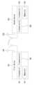
도 7은 본 개시가 적용될 수 있는 무선 통신 시스템에서 다중 패널 단말을 예시하는 도면이다.
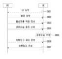
도 8은 본 개시의 일 실시예에 따른 상향링크 신호 송수신 방법에 대한 기지국과 단말 간의 시그널링 절차를 예시하는 도면이다.
도 9는 본 개시의 일 실시예에 따른 상향링크 송수신 방법에 대한 단말의 동작을 예시하는 도면이다.
도 10은 본 개시의 일 실시예에 따른 상향링크 송수신 방법에 대한 기지국의 동작을 예시하는 도면이다.
도 11은 본 개시의 일 실시예에 따른 무선 통신 장치의 블록 구성도를 예시한다.BRIEF DESCRIPTION OF THE DRAWINGS The accompanying drawings, which are included as part of the detailed description to aid understanding of the present disclosure, provide embodiments of the present disclosure and, together with the detailed description, describe technical features of the present disclosure.
1 illustrates the structure of a wireless communication system to which the present disclosure may be applied.
2 illustrates a frame structure in a wireless communication system to which the present disclosure can be applied.
3 illustrates a resource grid in a wireless communication system to which the present disclosure may be applied.
4 illustrates a physical resource block in a wireless communication system to which the present disclosure may be applied.
5 illustrates a slot structure in a wireless communication system to which the present disclosure may be applied.
6 illustrates physical channels used in a wireless communication system to which the present disclosure can be applied and a general signal transmission/reception method using them.
7 is a diagram illustrating a multi-panel terminal in a wireless communication system to which the present disclosure can be applied.
8 is a diagram illustrating a signaling procedure between a base station and a terminal for a method for transmitting and receiving an uplink signal according to an embodiment of the present disclosure.
9 is a diagram illustrating an operation of a terminal for an uplink transmission/reception method according to an embodiment of the present disclosure.
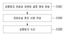
10 is a diagram illustrating an operation of a base station for an uplink transmission/reception method according to an embodiment of the present disclosure.
11 illustrates a block configuration diagram of a wireless communication device according to an embodiment of the present disclosure.
이하, 본 개시에 따른 바람직한 실시 형태를 첨부된 도면을 참조하여 상세하게 설명한다. 첨부된 도면과 함께 이하에 개시될 상세한 설명은 본 개시의 예시적인 실시형태를 설명하고자 하는 것이며, 본 개시가 실시될 수 있는 유일한 실시형태를 나타내고자 하는 것이 아니다. 이하의 상세한 설명은 본 개시의 완전한 이해를 제공하기 위해서 구체적 세부사항을 포함한다. 그러나, 당업자는 본 개시가 이러한 구체적 세부사항 없이도 실시될 수 있음을 안다.Hereinafter, preferred embodiments according to the present disclosure will be described in detail with reference to the accompanying drawings. The detailed description set forth below in conjunction with the accompanying drawings is intended to describe exemplary embodiments of the present disclosure, and is not intended to represent the only embodiments in which the present disclosure may be practiced. The following detailed description includes specific details for the purpose of providing a thorough understanding of the present disclosure. However, one skilled in the art recognizes that the present disclosure may be practiced without these specific details.
몇몇 경우, 본 개시의 개념이 모호해지는 것을 피하기 위하여 공지의 구조 및 장치는 생략되거나, 각 구조 및 장치의 핵심기능을 중심으로 한 블록도 형식으로 도시될 수 있다.In some cases, in order to avoid obscuring the concept of the present disclosure, well-known structures and devices may be omitted or may be shown in block diagram form centering on core functions of each structure and device.
본 개시에 있어서, 어떤 구성요소가 다른 구성요소와 "연결", "결합" 또는 "접속"되어 있다고 할 때, 이는 직접적인 연결관계 뿐만 아니라, 그 사이에 또 다른 구성요소가 존재하는 간접적인 연결관계도 포함할 수 있다. 또한 본 개시에서 용어 "포함한다" 또는 "가진다"는 언급된 특징, 단계, 동작, 요소 및/또는 구성요소의 존재를 특정하지만, 하나 이상의 다른 특징, 단계, 동작, 요소, 구성요소 및/또는 이들의 그룹의 존재 또는 추가를 배제하지 않는다.In the present disclosure, when a component is said to be "connected", "coupled" or "connected" to another component, this is not only a direct connection relationship, but also an indirect connection relationship between which another component exists. may also be included. Also in this disclosure, the terms "comprises" or "has" specify the presence of a stated feature, step, operation, element and/or component, but not one or more other features, steps, operations, elements, components and/or components. The presence or addition of groups of these is not excluded.
본 개시에 있어서, "제 1", "제 2" 등의 용어는 하나의 구성요소를 다른 구성요소로부터 구별하는 목적으로만 사용되고 구성요소들을 제한하기 위해서 사용되지 않으며, 특별히 언급되지 않는 한 구성요소들 간의 순서 또는 중요도 등을 한정하지 않는다. 따라서, 본 개시의 범위 내에서 일 실시예에서의 제 1 구성요소는 다른 실시예에서 제 2 구성요소라고 칭할 수도 있고, 마찬가지로 일 실시예에서의 제 2 구성요소를 다른 실시예에서 제 1 구성요소라고 칭할 수도 있다.In the present disclosure, terms such as “first” and “second” are used only for the purpose of distinguishing one component from another component and are not used to limit the components, unless otherwise specified. The order or importance among them is not limited. Accordingly, within the scope of the present disclosure, a first component in one embodiment may be referred to as a second component in another embodiment, and similarly, a second component in one embodiment may be referred to as a first component in another embodiment. can also be called
본 개시에서 사용된 용어는 특정 실시예에 대한 설명을 위한 것이며 청구범위를 제한하려는 것이 아니다. 실시예의 설명 및 첨부된 청구범위에서 사용되는 바와 같이, 단수 형태는 문맥상 명백하게 다르게 나타내지 않는 한 복수 형태도 포함하도록 의도한 것이다. 본 개시에 사용된 용어 "및/또는"은 관련된 열거 항목 중의 하나를 지칭할 수도 있고, 또는 그 중의 둘 이상의 임의의 및 모든 가능한 조합을 지칭하고 포함하는 것을 의미한다. 또한, 본 개시에서 단어들 사이의 "/"는 달리 설명되지 않는 한 "및/또는"과 동일한 의미를 가진다.Terminology used in this disclosure is for description of specific embodiments and is not intended to limit the scope of the claims. As used in the description of the embodiments and the appended claims, the singular forms are intended to include the plural forms as well unless the context clearly dictates otherwise. As used in this disclosure, the term “and/or” may refer to any one of the associated listed items, or is meant to refer to and include any and all possible combinations of two or more of them. Also, in this disclosure, “/” between words has the same meaning as “and/or” unless otherwise stated.
본 개시는 무선 통신 네트워크 또는 무선 통신 시스템을 대상으로 설명하며, 무선 통신 네트워크에서 이루어지는 동작은 해당 무선 통신 네트워크를 관할하는 장치(예를 들어 기지국)에서 네트워크를 제어하고 신호를 송신(transmit) 또는 수신(receive)하는 과정에서 이루어지거나, 해당 무선 네트워크에 결합한 단말에서 네트워크와의 또는 단말간의 신호를 송신 또는 수신하는 과정에서 이루어질 수 있다.The present disclosure describes a wireless communication network or wireless communication system, and operations performed in the wireless communication network control the network and transmit or receive signals in a device (for example, a base station) in charge of the wireless communication network. It can be done in the process of receiving (receive) or in the process of transmitting or receiving signals from a terminal coupled to the wireless network to or between terminals.
본 개시에서, 채널을 송신 또는 수신한다는 것은 해당 채널을 통해서 정보 또는 신호를 송신 또는 수신한다는 의미를 포함한다. 예를 들어, 제어 채널을 송신한다는 것은, 제어 채널을 통해서 제어 정보 또는 신호를 송신한다는 것을 의미한다. 유사하게, 데이터 채널을 송신한다는 것은, 데이터 채널을 통해서 데이터 정보 또는 신호를 송신한다는 것을 의미한다.In the present disclosure, transmitting or receiving a channel includes the meaning of transmitting or receiving information or a signal through a corresponding channel. For example, transmitting a control channel means transmitting control information or a signal through the control channel. Similarly, transmitting a data channel means transmitting data information or a signal through the data channel.
이하에서, 하향링크(DL: downlink)는 기지국에서 단말로의 통신을 의미하며, 상향링크(UL: uplink)는 단말에서 기지국으로의 통신을 의미한다. 하향링크에서 송신기는 기지국의 일부이고, 수신기는 단말의 일부일 수 있다. 상향링크에서 송신기는 단말의 일부이고, 수신기는 기지국의 일부일 수 있다. 기지국은 제1 통신 장치로, 단말은 제2 통신 장치로 표현될 수도 있다. 기지국(BS: Base Station)은 고정국(fixed station), Node B, eNB(evolved-NodeB), gNB(Next Generation NodeB), BTS(base transceiver system), 액세스 포인트(AP: Access Point), 네트워크(5G 네트워크), AI(Artificial Intelligence) 시스템/모듈, RSU(road side unit), 로봇(robot), 드론(UAV: Unmanned Aerial Vehicle), AR(Augmented Reality)장치, VR(Virtual Reality)장치 등의 용어에 의해 대체될 수 있다. 또한, 단말(Terminal)은 고정되거나 이동성을 가질 수 있으며, UE(User Equipment), MS(Mobile Station), UT(user terminal), MSS(Mobile Subscriber Station), SS(Subscriber Station), AMS(Advanced Mobile Station), WT(Wireless terminal), MTC(Machine-Type Communication) 장치, M2M(Machine-to-Machine) 장치, D2D(Device-to-Device) 장치, 차량(vehicle), RSU(road side unit), 로봇(robot), AI(Artificial Intelligence) 모듈, 드론(UAV: Unmanned Aerial Vehicle), AR(Augmented Reality)장치, VR(Virtual Reality)장치 등의 용어로 대체될 수 있다.Hereinafter, downlink (DL) means communication from a base station to a terminal, and uplink (UL) means communication from a terminal to a base station. In downlink, a transmitter may be part of a base station and a receiver may be part of a terminal. In uplink, a transmitter may be a part of a terminal and a receiver may be a part of a base station. A base station may be expressed as a first communication device, and a terminal may be expressed as a second communication device. A base station (BS) includes a fixed station, a Node B, an evolved-NodeB (eNB), a Next Generation NodeB (gNB), a base transceiver system (BTS), an access point (AP), and a network (5G Network), AI (Artificial Intelligence) system/module, RSU (road side unit), robot, drone (UAV: Unmanned Aerial Vehicle), AR (Augmented Reality) device, VR (Virtual Reality) device, etc. can be replaced by In addition, a terminal may be fixed or mobile, and a user equipment (UE), a mobile station (MS), a user terminal (UT), a mobile subscriber station (MSS), a subscriber station (SS), and an advanced mobile (AMS) Station), WT (Wireless terminal), MTC (Machine-Type Communication) device, M2M (Machine-to-Machine) device, D2D (Device-to-Device) device, vehicle, RSU (road side unit), It can be replaced with terms such as robot, AI (Artificial Intelligence) module, drone (UAV: Unmanned Aerial Vehicle), AR (Augmented Reality) device, VR (Virtual Reality) device, etc.
이하의 기술은 CDMA, FDMA, TDMA, OFDMA, SC-FDMA 등과 같은 다양한 무선 접속 시스템에 사용될 수 있다. CDMA는 UTRA(Universal Terrestrial Radio Access)나 CDMA2000과 같은 무선 기술로 구현될 수 있다. TDMA는 GSM(Global System for Mobile communications)/GPRS(General Packet Radio Service)/EDGE(Enhanced Data Rates for GSM Evolution)와 같은 무선 기술로 구현될 수 있다. OFDMA는 IEEE 802.11(Wi-Fi), IEEE 802.16(WiMAX), IEEE 802-20, E-UTRA(Evolved UTRA) 등과 같은 무선 기술로 구현될 수 있다. UTRA는 UMTS(Universal Mobile Telecommunications System)의 일부이다. 3GPP(3rd Generation Partnership Project) LTE(Long Term Evolution)은 E-UTRA를 사용하는 E-UMTS(Evolved UMTS)의 일부이고 LTE-A(Advanced)/LTE-A pro는 3GPP LTE의 진화된 버전이다. 3GPP NR(New Radio or New Radio Access Technology)는 3GPP LTE/LTE-A/LTE-A pro의 진화된 버전이다.The following techniques may be used in various radio access systems such as CDMA, FDMA, TDMA, OFDMA, SC-FDMA, and the like. CDMA may be implemented with a radio technology such as Universal Terrestrial Radio Access (UTRA) or CDMA2000. TDMA may be implemented with a radio technology such as Global System for Mobile communications (GSM)/General Packet Radio Service (GPRS)/Enhanced Data Rates for GSM Evolution (EDGE). OFDMA may be implemented with radio technologies such as IEEE 802.11 (Wi-Fi), IEEE 802.16 (WiMAX), IEEE 802-20, and Evolved UTRA (E-UTRA). UTRA is part of the Universal Mobile Telecommunications System (UMTS). 3rd Generation Partnership Project (3GPP) Long Term Evolution (LTE) is a part of Evolved UMTS (E-UMTS) using E-UTRA, and LTE-A (Advanced) / LTE-A pro is an evolved version of 3GPP LTE. 3GPP NR (New Radio or New Radio Access Technology) is an evolved version of 3GPP LTE/LTE-A/LTE-A pro.
설명을 명확하게 하기 위해, 3GPP 통신 시스템(예를 들어, LTE-A, NR)을 기반으로 설명하지만 본 개시의 기술적 사상이 이에 제한되는 것은 아니다. LTE는 3GPP TS(Technical Specification) 36.xxx Release 8 이후의 기술을 의미한다. 세부적으로, 3GPP TS 36.xxx Release 10 이후의 LTE 기술은 LTE-A로 지칭되고, 3GPP TS 36.xxx Release 13 이후의 LTE 기술은 LTE-A pro로 지칭된다. 3GPP NR은 TS 38.xxx Release 15 이후의 기술을 의미한다. LTE/NR은 3GPP 시스템으로 지칭될 수 있다. "xxx"는 표준 문서 세부 번호를 의미한다. LTE/NR은 3GPP 시스템으로 통칭될 수 있다. 본 개시의 설명에 사용된 배경기술, 용어, 약어 등에 관해서는 본 개시 이전에 공개된 표준 문서에 기재된 사항을 참조할 수 있다. 예를 들어, 다음 문서를 참조할 수 있다.For clarity, the description is based on a 3GPP communication system (eg, LTE-A, NR), but the technical spirit of the present disclosure is not limited thereto. LTE refers to technology after 3GPP Technical Specification (TS) 36.xxx
3GPP LTE의 경우, TS 36.211(물리 채널들 및 변조), TS 36.212(다중화 및 채널 코딩), TS 36.213(물리 계층 절차들), TS 36.300(전반적인 설명), TS 36.331(무선 자원 제어)을 참조할 수 있다.For 3GPP LTE, see TS 36.211 (Physical Channels and Modulation), TS 36.212 (Multiplexing and Channel Coding), TS 36.213 (Physical Layer Procedures), TS 36.300 (General Description), TS 36.331 (Radio Resource Control). can
3GPP NR의 경우, TS 38.211(물리 채널들 및 변조), TS 38.212(다중화 및 채널 코딩), TS 38.213(제어를 위한 물리 계층 절차들), TS 38.214(데이터를 위한 물리 계층 절차들), TS 38.300(NR 및 NG-RAN(New Generation-Radio Access Network) 전반적인 설명), TS 38.331(무선 자원 제어 프로토콜 규격)을 참조할 수 있다.For 3GPP NR, TS 38.211 (Physical Channels and Modulation), TS 38.212 (Multiplexing and Channel Coding), TS 38.213 (Physical Layer Procedures for Control), TS 38.214 (Physical Layer Procedures for Data), TS 38.300 (General description of NR and New Generation-Radio Access Network (NG-RAN)) and TS 38.331 (Radio Resource Control Protocol Specification) may be referred to.
본 개시에서 사용될 수 있는 용어들의 약자는 다음과 같이 정의된다.Abbreviations of terms that may be used in this disclosure are defined as follows.
- BM: 빔 관리(beam management)- BM: beam management
- CQI: 채널 품질 지시자(channel quality indicator)- CQI: channel quality indicator
- CRI: 채널 상태 정보 - 참조 신호 자원 지시자(channel state information - reference signal resource indicator)- CRI: channel state information - reference signal resource indicator (channel state information - reference signal resource indicator)
- CSI: 채널 상태 정보(channel state information)- CSI: channel state information
- CSI-IM: 채널 상태 정보 - 간섭 측정(channel state information - interference measurement)- CSI-IM: channel state information - interference measurement
- CSI-RS: 채널 상태 정보 - 참조 신호(channel state information - reference signal)- CSI-RS: channel state information - reference signal (channel state information - reference signal)
- DMRS: 복조 참조 신호(demodulation reference signal)- DMRS: demodulation reference signal
- FDM: 주파수 분할 다중화(frequency division multiplexing)- FDM: frequency division multiplexing
- FFT: 고속 푸리에 변환(fast Fourier transform)- FFT: fast Fourier transform
- IFDMA: 인터리빙된 주파수 분할 다중 액세스(interleaved frequency division multiple access)- IFDMA: interleaved frequency division multiple access
- IFFT: 역 고속 푸리에 변환(inverse fast Fourier transform)- IFFT: inverse fast Fourier transform
- L1-RSRP: 제1 레이어 참조 신호 수신 파워(Layer 1 reference signal received power)- L1-RSRP:
- L1-RSRQ: 제1 레이어 참조 신호 수신 품질(Layer 1 reference signal received quality)- L1-RSRQ:
- MAC: 매체 액세스 제어(medium access control)- MAC: medium access control
- NZP: 논-제로 파워(non-zero power)- NZP: non-zero power
- OFDM: 직교 주파수 분할 다중화(orthogonal frequency division multiplexing)- OFDM: orthogonal frequency division multiplexing (orthogonal frequency division multiplexing)
- PDCCH: 물리 하향링크 제어 채널(physical downlink control channel)- PDCCH: physical downlink control channel
- PDSCH: 물리 하향링크 공유 채널(physical downlink shared channel)- PDSCH: physical downlink shared channel
- PMI: 프리코딩 행렬 지시자(precoding matrix indicator)- PMI: precoding matrix indicator
- RE: 자원 요소(resource element)- RE: resource element
- RI: 랭크 지시자(Rank indicator)- RI: Rank indicator
- RRC: 무선 자원 제어(radio resource control)- RRC: radio resource control (radio resource control)
- RSSI: 수신 신호 강도 지시자(received signal strength indicator)- RSSI: received signal strength indicator
- Rx: 수신(Reception)- Rx: Reception
- QCL: 준-동일 위치(quasi co-location)- QCL: quasi co-location
- SINR: 신호 대 간섭 및 잡음비(signal to interference and noise ratio)- SINR: signal to interference and noise ratio
- SSB (또는 SS/PBCH block): 동기 신호 블록(프라이머리 동기 신호(PSS: primary synchronization signal), 세컨더리 동기 신호(SSS: secondary synchronization signal) 및 물리 방송 채널(PBCH: physical broadcast channel)을 포함)-SSB (or SS/PBCH block): Synchronization signal block (including primary synchronization signal (PSS), secondary synchronization signal (SSS) and physical broadcast channel (PBCH))
- TDM: 시간 분할 다중화(time division multiplexing)- TDM: time division multiplexing
- TRP: 전송 및 수신 포인트(transmission and reception point)- TRP: transmission and reception point
- TRS: 트래킹 참조 신호(tracking reference signal)- TRS: tracking reference signal
- Tx: 전송(transmission)- Tx: transmission
- UE: 사용자 장치(user equipment)- UE: user equipment
- ZP: 제로 파워(zero power)- ZP: zero power
시스템 일반system general
더욱 많은 통신 기기들이 더욱 큰 통신 용량을 요구하게 됨에 따라, 기존의 무선 액세스 기술(RAT: radio access technology)에 비해 향상된 모바일 브로드밴드(mobile broadband) 통신에 대한 필요성이 대두되고 있다. 또한 다수의 기기 및 사물들을 연결하여 언제 어디서나 다양한 서비스를 제공하는 매시브(massive) MTC(Machine Type Communications) 역시 차세대 통신에서 고려될 주요 이슈 중 하나이다. 뿐만 아니라 신뢰도(reliability) 및 지연(latency)에 민감한 서비스/단말을 고려한 통신 시스템 디자인이 논의되고 있다. 이와 같이 eMBB(enhanced mobile broadband communication), Mmtc(massive MTC), URLLC (Ultra-Reliable and Low Latency Communication) 등을 고려한 차세대 RAT의 도입이 논의되고 있으며, 본 개시에서는 편의상 해당 기술을 NR이라고 부른다. NR은 5G RAT의 일례를 나타낸 표현이다.As more and more communication devices require greater communication capacity, a need for improved mobile broadband communication compared to existing radio access technology (RAT) has emerged. In addition, massive MTC (Machine Type Communications), which provides various services anytime and anywhere by connecting multiple devices and objects, is also one of the major issues to be considered in next-generation communication. In addition, communication system design considering reliability and latency-sensitive services/terminals is being discussed. As described above, introduction of a next-generation RAT considering eMBB (enhanced mobile broadband communication), Mmtc (massive MTC), URLLC (Ultra-Reliable and Low Latency Communication), etc. is being discussed, and in the present disclosure, the corresponding technology is referred to as NR for convenience. NR is an expression showing an example of 5G RAT.
NR을 포함하는 새로운 RAT 시스템은 OFDM 전송 방식 또는 이와 유사한 전송 방식을 사용한다. 새로운 RAT 시스템은 LTE의 OFDM 파라미터들과는 다른 OFDM 파라미터들을 따를 수 있다. 또는 새로운 RAT 시스템은 기존의 LTE/LTE-A의 뉴머롤로지(numerology)를 그대로 따르나 더 큰 시스템 대역폭(예를 들어, 100MHz)를 지원할 수 있다. 또는 하나의 셀이 복수 개의 numerology들을 지원할 수도 있다. 즉, 서로 다른 numerology로 동작하는 하는 단말들이 하나의 셀 안에서 공존할 수 있다.A new RAT system including NR uses an OFDM transmission scheme or a transmission scheme similar thereto. The new RAT system may follow OFDM parameters different from those of LTE. Alternatively, the new RAT system follows the numerology of the existing LTE/LTE-A as it is, but may support a larger system bandwidth (eg, 100 MHz). Alternatively, one cell may support a plurality of numerologies. That is, terminals operating with different numerologies can coexist in one cell.
numerology는 주파수 영역에서 하나의 서브캐리어 간격(subcarrier spacing)에 대응한다. 참조 서브캐리어 간격(Reference subcarrier spacing)을 정수 N으로 스케일링(scaling)함으로써, 상이한 numerology가 정의될 수 있다.A numerology corresponds to one subcarrier spacing in the frequency domain. Different numerologies can be defined by scaling the reference subcarrier spacing by an integer N.
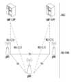
도 1은 본 개시가 적용될 수 있는 무선 통신 시스템의 구조를 예시한다.1 illustrates the structure of a wireless communication system to which the present disclosure may be applied.
도 1을 참조하면, NG-RAN은 NG-RA(NG-Radio Access) 사용자 평면(즉, 새로운 AS(access stratum) 서브계층/PDCP(Packet Data Convergence Protocol)/RLC(Radio Link Control)/MAC/PHY) 및 UE에 대한 제어 평면(RRC) 프로토콜 종단을 제공하는 gNB들로 구성된다. 상기 gNB는 Xn 인터페이스를 통해 상호 연결된다. 상기 gNB는 또한, NG 인터페이스를 통해 NGC(New Generation Core)로 연결된다. 보다 구체적으로는, 상기 gNB는 N2 인터페이스를 통해 AMF(Access and Mobility Management Function)로, N3 인터페이스를 통해 UPF(User Plane Function)로 연결된다.Referring to FIG. 1, the NG-RAN is a NG-RA (NG-Radio Access) user plane (ie, a new AS (access stratum) sublayer / PDCP (Packet Data Convergence Protocol) / RLC (Radio Link Control) / MAC / PHY) and control plane (RRC) protocol termination to the UE. The gNBs are interconnected through an Xn interface. The gNB is also connected to a New Generation Core (NGC) through an NG interface. More specifically, the gNB is connected to an Access and Mobility Management Function (AMF) through an N2 interface and to a User Plane Function (UPF) through an N3 interface.
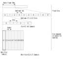
도 2는 본 개시가 적용될 수 있는 무선 통신 시스템에서 프레임 구조를 예시한다.2 illustrates a frame structure in a wireless communication system to which the present disclosure can be applied.
NR 시스템은 다수의 뉴머롤로지(numerology)들을 지원할 수 있다. 여기서, numerology는 서브캐리어 간격(subcarrier spacing)과 순환 전치(CP: Cyclic Prefix) 오버헤드에 의해 정의될 수 있다. 이때, 다수의 서브캐리어 간격은 기본(참조) 서브캐리어 간격을 정수 N(또는, μ)으로 스케일링(scaling) 함으로써 유도될 수 있다. 또한, 매우 높은 반송파 주파수에서 매우 낮은 서브캐리어 간격을 이용하지 않는다고 가정될지라도, 이용되는 numerology는 주파수 대역과 독립적으로 선택될 수 있다. 또한, NR 시스템에서는 다수의 numerology에 따른 다양한 프레임 구조들이 지원될 수 있다.An NR system can support multiple numerologies. Here, numerology may be defined by subcarrier spacing and Cyclic Prefix (CP) overhead. In this case, the multiple subcarrier spacing can be derived by scaling the basic (reference) subcarrier spacing by an integer N (or μ). Also, although it is assumed that very low subcarrier spacing is not used at very high carrier frequencies, the numerology used can be selected independently of the frequency band. Also, in the NR system, various frame structures according to a plurality of numerologies may be supported.
이하, NR 시스템에서 고려될 수 있는 OFDM numerology 및 프레임 구조를 살펴본다. NR 시스템에서 지원되는 다수의 OFDM numerology들은 아래 표 1과 같이 정의될 수 있다.Hereinafter, OFDM numerology and frame structure that can be considered in the NR system will be described. Multiple OFDM numerologies supported in the NR system can be defined as shown in Table 1 below.
NR은 다양한 5G 서비스들을 지원하기 위한 다수의 numerology(또는 서브캐리어 간격(SCS: subcarrier spacing))를 지원한다. 예를 들어, SCS가 15kHz인 경우, 전통적인 셀룰러 밴드들에서의 넓은 영역(wide area)를 지원하며, SCS가 30kHz/60kHz인 경우, 밀집한-도시(dense-urban), 더 낮은 지연(lower latency) 및 더 넓은 캐리어 대역폭(wider carrier bandwidth)를 지원하며, SCS가 60kHz 또는 그보다 높은 경우, 위상 잡음(phase noise)를 극복하기 위해 24.25GHz보다 큰 대역폭을 지원한다. NR 주파수 밴드(frequency band)는 2가지 타입(FR1, FR2)의 주파수 범위(frequency range)로 정의된다. FR1, FR2는 아래 표 2와 같이 구성될 수 있다. 또한, FR2는 밀리미터 웨이브(mmW: millimeter wave)를 의미할 수 있다.NR supports multiple numerologies (or subcarrier spacing (SCS)) to support various 5G services. For example, when the SCS is 15 kHz, it supports a wide area in traditional cellular bands, and when the SCS is 30 kHz/60 kHz, dense-urban, lower latency and a wider carrier bandwidth, and when the SCS is 60 kHz or higher, a bandwidth greater than 24.25 GHz is supported to overcome phase noise. The NR frequency band is defined as two types of frequency ranges (FR1 and FR2). FR1 and FR2 may be configured as shown in Table 2 below. Also, FR2 may mean millimeter wave (mmW).
NR 시스템에서의 프레임 구조(frame structure)와 관련하여, 시간 영역의 다양한 필드의 크기는 Tc=1/(Δfmax·Nf) 의 시간 단위의 배수로 표현된다. 여기에서, Δfmax=480·103 Hz 이고, Nf=4096 이다. 하향링크(downlink) 및 상향링크(uplink) 전송은 Tf=1/(ΔfmaxNf/100)·Tc=10ms 의 구간을 가지는 무선 프레임(radio frame)으로 구성(organized)된다. 여기에서, 무선 프레임은 각각 Tsf=(ΔfmaxNf/1000)·Tc=1ms의 구간을 가지는 10 개의 서브프레임(subframe)들로 구성된다. 이 경우, 상향링크에 대한 한 세트의 프레임들 및 하향링크에 대한 한 세트의 프레임들이 존재할 수 있다. 또한, 단말로부터의 상향링크 프레임 번호 i에서의 전송은 해당 단말에서의 해당 하향링크 프레임의 시작보다 TTA=(NTA+NTA,offset)Tc 이전에 시작해야 한다. 서브캐리어 간격 구성 μ 에 대하여, 슬롯(slot)들은 서브프레임 내에서 nsμ∈{0,..., Nslotsubframe,μ-1} 의 증가하는 순서로 번호가 매겨지고, 무선 프레임 내에서 ns,fμ∈{0,..., Nslotframe,μ-1} 의 증가하는 순서로 번호가 매겨진다. 하나의 슬롯은 Nsymbslot 의 연속하는 OFDM 심볼들로 구성되고, Nsymbslot 는, CP에 따라 결정된다. 서브프레임에서 슬롯 nsμ 의 시작은 동일 서브프레임에서 OFDM 심볼 nsμNsymbslot 의 시작과 시간적으로 정렬된다. 모든 단말이 동시에 송신 및 수신을 할 수 있는 것은 아니며, 이는 하향링크 슬롯(downlink slot) 또는 상향링크 슬롯(uplink slot)의 모든 OFDM 심볼들이 이용될 수는 없다는 것을 의미한다. 표 3은 일반 CP에서 슬롯 별 OFDM 심볼의 개수(Nsymbslot), 무선 프레임 별 슬롯의 개수(Nslotframe,μ), 서브프레임 별 슬롯의 개수(Nslotsubframe,μ)를 나타내며, 표 4는 확장 CP에서 슬롯 별 OFDM 심볼의 개수, 무선 프레임 별 슬롯의 개수, 서브프레임 별 슬롯의 개수를 나타낸다.Regarding the frame structure in the NR system, the size of various fields in the time domain is expressed as a multiple of a time unit of Tc =1/(Δfmax ·Nf ). Here, Δfmax =480 103 Hz and Nf =4096. Downlink and uplink transmission is organized as a radio frame having a section of Tf =1/(Δfmax Nf /100)·Tc =10 ms. Here, each radio frame is Tsf =(Δfmax Nf /1000) Tc =1msIt consists of 10 subframes having a section of . In this case, there may be one set of frames for uplink and one set of frames for downlink. In addition, transmission in uplink frame number i from the terminal must start before TTA =(NTA +NTA,offset )Tc before the start of the corresponding downlink frame in the corresponding terminal. For subcarrier spacing configuration μ, slots are numbered in increasing order of nsμ ∈{0,..., Nslotsubframe,μ -1} within a subframe, and within a radio frame They are numbered in increasing order ns,fμ ∈{0,..., Nslotframe,μ -1}. One slot is composed of consecutive OFDM symbols of Nsymbslots , and Nsymbslots are determined according to CP. The start of slot nsμ in a subframe is temporally aligned with the start of OFDM symbol nsμ Nsymbslot in the same subframe. Not all terminals can simultaneously transmit and receive, which means that not all OFDM symbols in a downlink slot or uplink slot can be used. Table 3 shows the number of OFDM symbols per slot (Nsymbslot ), the number of slots per radio frame (Nslotframe, μ ), and the number of slots per subframe (Nslotsubframe, μ ) in the general CP. Table 4 represents the number of OFDM symbols per slot, the number of slots per radio frame, and the number of slots per subframe in the extended CP.
도 2는, μ=2인 경우(SCS가 60kHz)의 일례로서, 표 3을 참고하면 1 서브프레임(subframe)은 4개의 슬롯(slot)들을 포함할 수 있다. 도 2에 도시된 1 subframe={1,2,4} slot은 일례로서, 1 subframe에 포함될 수 있는 slot(들)의 개수는 표 3 또는 표 4와 같이 정의된다. 또한, 미니 슬롯(mini-slot)은 2, 4 또는 7 심볼들을 포함하거나 그 보다 더 많은 또는 더 적은 심볼들을 포함할 수 있다.NR 시스템에서의 물리 자원(physical resource)과 관련하여, 안테나 포트(antenna port), 자원 그리드(resource grid), 자원 요소(resource element), 자원 블록(resource block), 캐리어 파트(carrier part) 등이 고려될 수 있다. 이하, NR 시스템에서 고려될 수 있는 상기 물리 자원들에 대해 구체적으로 살펴본다.2 is an example of a case where μ = 2 (SCS is 60 kHz), and referring to Table 3, one subframe may include 4 slots. 1 subframe = {1,2,4} slot shown in FIG. 2 is an example, and the number of slot(s) that can be included in 1 subframe is defined as shown in Table 3 or Table 4. In addition, a mini-slot may include 2, 4, or 7 symbols, more or less symbols. Regarding a physical resource in the NR system, an antenna port ( antenna port), resource grid, resource element, resource block, carrier part, etc. may be considered. Hereinafter, the physical resources that can be considered in the NR system will be described in detail.
먼저, 안테나 포트와 관련하여, 안테나 포트는 안테나 포트 상의 심볼이 운반되는 채널이 동일한 안테나 포트 상의 다른 심볼이 운반되는 채널로부터 추론될 수 있도록 정의된다. 하나의 안테나 포트 상의 심볼이 운반되는 채널의 광범위 특성(large-scale property)이 다른 안테나 포트 상의 심볼이 운반되는 채널로부터 유추될 수 있는 경우, 2 개의 안테나 포트는 QC/QCL(quasi co-located 혹은 quasi co-location) 관계에 있다고 할 수 있다. 여기서, 상기 광범위 특성은 지연 확산(Delay spread), 도플러 확산(Doppler spread), 주파수 쉬프트(Frequency shift), 평균 수신 파워(Average received power), 수신 타이밍(Received Timing) 중 하나 이상을 포함한다.First, with respect to the antenna port, the antenna port is defined such that the channel on which a symbol on the antenna port is carried can be inferred from the channel on which other symbols on the same antenna port are carried. If the large-scale properties of the channel on which the symbols on one antenna port are carried can be inferred from the channel on which the symbols on the other antenna port are carried, then the two antenna ports are quasi co-located or QC/QCL (quasi co-located or quasi co-location). Here, the wide range characteristic includes one or more of delay spread, Doppler spread, frequency shift, average received power, and received timing.
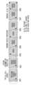
도 3은 본 개시가 적용될 수 있는 무선 통신 시스템에서 자원 그리드(resource grid)를 예시한다.3 illustrates a resource grid in a wireless communication system to which the present disclosure may be applied.
도 3을 참조하면, 자원 그리드가 주파수 영역 상으로 NRBμNscRB 서브캐리어들로 구성되고, 하나의 서브프레임이 14·2μ OFDM 심볼들로 구성되는 것을 예시적으로 기술하나, 이에 한정되는 것은 아니다. NR 시스템에서, 전송되는 신호(transmitted signal)는 NRBμNscRB 서브캐리어들로 구성되는 하나 또는 그 이상의 자원 그리드들 및 2μNsymb(μ) 의 OFDM 심볼들에 의해 설명된다. 여기서, NRBμ≤NRBmax,μ 이다. 상기 NRBmax,μ 는 최대 전송 대역폭을 나타내고, 이는, numerology들 뿐만 아니라 상향링크와 하향링크 간에도 달라질 수 있다. 이 경우, μ 및 안테나 포트 p 별로 하나의 자원 그리드가 설정될 수 있다. μ 및 안테나 포트 p에 대한 자원 그리드의 각 요소는 자원 요소(resource element)로 지칭되며, 인덱스 쌍 (k,l')에 의해 고유적으로 식별된다. 여기에서, k=0,...,NRBμNscRB-1 는 주파수 영역 상의 인덱스이고, l'=0,...,2μNsymb(μ)-1 는 서브프레임 내에서 심볼의 위치를 지칭한다. 슬롯에서 자원 요소를 지칭할 때에는, 인덱스 쌍 (k,l) 이 이용된다. 여기서, l=0,...,Nsymbμ-1 이다. μ 및 안테나 포트 p에 대한 자원 요소 (k,l') 는 복소 값(complex value) ak,l'(p,μ) 에 해당한다. 혼동(confusion)될 위험이 없는 경우 혹은 특정 안테나 포트 또는 numerology가 특정되지 않은 경우에는, 인덱스들 p 및 μ 는 드롭(drop)될 수 있으며, 그 결과 복소 값은 ak,l'(p) 또는 ak,l' 이 될 수 있다. 또한, 자원 블록(resource block, RB)은 주파수 영역 상의 NscRB=12 연속적인 서브캐리어들로 정의된다.Referring to FIG. 3, a resource grid is composed of NRBμ NscRB subcarriers in the frequency domain, and one subframe is composed of 14 2μ OFDM symbols. However, it is limited thereto it is not going to be In an NR system, a transmitted signal is described by one or more resource grids consisting of NRBμ NscRB subcarriers and 2μ Nsymb(μ) OFDM symbols. Here, NRBμ ≤ NRBmax, μ . The NRBmax, μ represents the maximum transmission bandwidth, which may vary not only between numerologies but also between uplink and downlink. In this case, one resource grid may be set for each μ and antenna port p. Each element of the resource grid for μ and antenna port p is referred to as a resource element and is uniquely identified by an index pair (k, l'). Here, k=0,...,NRBμ NscRB -1 is an index on the frequency domain, and l'=0,...,2μ Nsymb(μ) -1 is a symbol in a subframe indicates the location of When referring to a resource element in a slot, an index pair (k,l) is used. Here, l=0,...,Nsymbμ -1. The resource element (k,l') for μ and antenna port p corresponds to a complex value ak,l'(p,μ) . In cases where there is no risk of confusion, or where a particular antenna port or numerology is not specified, the indices p and μ may be dropped, resulting in a complex value of ak,l'(p) or It can be ak,l' . In addition, a resource block (RB) is defined as NscRB =12 consecutive subcarriers in the frequency domain.
포인트(point) A는 자원 블록 그리드의 공통 기준 포인트(common reference point)로서 역할을 하며 다음과 같이 획득된다.Point A serves as a common reference point of the resource block grid and is obtained as follows.
- 프라이머리 셀(PCell: Primary Cell) 다운링크에 대한 offsetToPointA는 초기 셀 선택을 위해 단말에 의해 사용된 SS/PBCH block과 겹치는 가장 낮은 자원 블록의 가장 낮은 서브 캐리어와 point A 간의 주파수 오프셋을 나타낸다. FR1에 대해 15kHz 서브캐리어 간격 및 FR2에 대해 60kHz 서브캐리어 간격을 가정한 리소스 블록 단위(unit)들로 표현된다.- OffsetToPointA for primary cell (PCell) downlink represents the frequency offset between point A and the lowest subcarrier of the lowest resource block overlapping the SS/PBCH block used by the UE for initial cell selection. It is expressed in resource block units assuming a 15 kHz subcarrier spacing for FR1 and a 60 kHz subcarrier spacing for FR2.
- absoluteFrequencyPointA는 ARFCN(absolute radio-frequency channel number)에서와 같이 표현된 point A의 주파수-위치를 나타낸다.-absoluteFrequencyPointA represents the frequency-position of point A expressed as in ARFCN (absolute radio-frequency channel number).
공통 자원 블록(common resource block)들은 서브캐리어 간격 설정 μ 에 대한 주파수 영역에서 0부터 위쪽으로 numbering된다. 서브캐리어 간격 설정 μ 에 대한 공통 자원 블록 0의 subcarrier 0의 중심은 'point A'와 일치한다. 주파수 영역에서 공통 자원 블록 번호 nCRBμ 와 서브캐리어 간격 설정 μ 에 대한 자원 요소(k,l)와의 관계는 아래 수학식 1과 같이 주어진다.Common resource blocks are numbered upward from 0 in the frequency domain for the subcarrier spacing μ. The center of

수학식 1에서, k는 k=0이 point A를 중심으로 하는 서브캐리어에 해당하도록 point A에 상대적으로 정의된다. 물리 자원 블록들은 대역폭 파트(BWP: bandwidth part) 내에서 0부터 NBWP,isize,μ-1 까지 번호가 매겨지고, i는 BWP의 번호이다. BWP i에서 물리 자원 블록 nPRB 와 공통 자원 블록 nCRB 간의 관계는 아래 수학식 2에 의해 주어진다.In

NBWP,istart,μ 는 BWP가 공통 자원 블록 0에 상대적으로 시작하는 공통 자원 블록이다.NBWP,istart,μ is a common resource block where BWP starts relative to
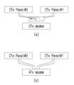
도 4는 본 개시가 적용될 수 있는 무선 통신 시스템에서 물리 자원 블록(physical resource block)을 예시한다. 그리고, 도 5는 본 개시가 적용될 수 있는 무선 통신 시스템에서 슬롯 구조를 예시한다.4 illustrates a physical resource block in a wireless communication system to which the present disclosure may be applied. And, Figure 5 illustrates a slot structure in a wireless communication system to which the present disclosure can be applied.
도 4 및 도 5를 참조하면, 슬롯은 시간 도메인에서 복수의 심볼을 포함한다. 예를 들어, 보통 CP의 경우 하나의 슬롯이 7개의 심볼을 포함하나, 확장 CP의 경우 하나의 슬롯이 6개의 심볼을 포함한다.4 and 5, a slot includes a plurality of symbols in the time domain. For example, in the case of a normal CP, one slot includes 7 symbols, but in the case of an extended CP, one slot includes 6 symbols.
반송파는 주파수 도메인에서 복수의 부반송파를 포함한다. RB(Resource Block)는 주파수 도메인에서 복수(예를 들어, 12)의 연속한 부반송파로 정의된다. BWP(Bandwidth Part)는 주파수 도메인에서 복수의 연속한 (물리) 자원 블록으로 정의되며, 하나의 numerology(예를 들어, SCS, CP 길이 등)에 대응될 수 있다. 반송파는 최대 N개(예를 들어, 5개)의 BWP를 포함할 수 있다. 데이터 통신은 활성화된 BWP를 통해서 수행되며, 하나의 단말한테는 하나의 BWP만 활성화될 수 있다. 자원 그리드에서 각각의 요소는 자원요소(RE: Resource Element)로 지칭되며, 하나의 복소 심볼이 매핑될 수 있다.A carrier includes a plurality of subcarriers in the frequency domain. A resource block (RB) is defined as a plurality of (eg, 12) consecutive subcarriers in the frequency domain. A bandwidth part (BWP) is defined as a plurality of contiguous (physical) resource blocks in the frequency domain, and may correspond to one numerology (eg, SCS, CP length, etc.). A carrier may include up to N (eg, 5) BWPs. Data communication is performed through an activated BWP, and only one BWP can be activated for one terminal. Each element in the resource grid is referred to as a resource element (RE), and one complex symbol may be mapped.
NR 시스템은 하나의 컴포넌트 캐리어(CC: Component Carrier) 당 최대 400 MHz까지 지원될 수 있다. 이러한 광대역 CC(wideband CC)에서 동작하는 단말이 항상 CC 전체에 대한 무선 주파수(RF: radio frequency) 칩(chip)를 켜둔 채로 동작한다면 단말 배터리 소모가 커질 수 있다. 혹은 하나의 광대역 CC 내에 동작하는 여러 활용 케이스들(예를 들어, eMBB, URLLC, Mmtc, V2X 등)을 고려할 때 해당 CC 내에 주파수 대역 별로 서로 다른 numerology(예를 들어, 서브캐리어 간격 등)가 지원될 수 있다. 혹은 단말 별로 최대 대역폭에 대한 능력(capability)이 다를 수 있다. 이를 고려하여 기지국은 광대역 CC의 전체 bandwidth이 아닌 일부 bandwidth에서만 동작하도록 단말에게 지시할 수 있으며, 해당 일부 bandwidth를 편의상 대역폭 부분(BWP: bandwidth part)로 정의한다. BWP는 주파수 축 상에서 연속한 RB들로 구성될 수 있으며, 하나의 numerology(예를 들어, 서브캐리어 간격, CP 길이, 슬롯/미니-슬롯 구간)에 대응될 수 있다.The NR system can support up to 400 MHz per component carrier (CC). If a terminal operating in such a wideband CC always operates with radio frequency (RF) chips for the entire CC turned on, battery consumption of the terminal may increase. Alternatively, when considering multiple use cases (eg eMBB, URLLC, Mmtc, V2X, etc.) operating within one broadband CC, different numerologies (eg subcarrier spacing, etc.) are supported for each frequency band within the CC. It can be. Alternatively, the capability for the maximum bandwidth may be different for each terminal. Considering this, the base station may instruct the terminal to operate only in a part of the bandwidth rather than the entire bandwidth of the wideband CC, and the part of the bandwidth is defined as a bandwidth part (BWP) for convenience. BWP may be composed of consecutive RBs on the frequency axis and may correspond to one numerology (eg, subcarrier spacing, CP length, slot/mini-slot period).
한편, 기지국은 단말에게 설정된 하나의 CC 내에서도 다수의 BWP를 설정할 수 있다. 예를 들어, PDCCH 모니터링 슬롯에서는 상대적으로 작은 주파수 영역을 차지하는 BWP를 설정하고, PDCCH에서 지시하는 PDSCH는 그보다 큰 BWP 상에 스케줄링될 수 있다. 혹은, 특정 BWP에 UE 들이 몰리는 경우 로드 밸런싱(load balancing)을 위해 일부 단말들을 다른 BWP로 설정할 수 있다. 혹은, 이웃 셀 간의 주파수 도메인 셀간 간섭 제거(frequency domain inter-cell interference cancellation) 등을 고려하여 전체 bandwidth 중 가운데 일부 스펙트럼(spectrum)을 배제하고 양쪽 BWP들을 동일 슬롯 내에서도 설정할 수 있다. 즉, 기지국은 광대역 CC와 연관된(association) 단말에게 적어도 하나의 DL/UL BWP를 설정할 수 있다. 기지국은 특정 시점에 설정된 DL/UL BWP(들) 중 적어도 하나의 DL/UL BWP를 (L1 시그널링 또는 MAC CE(Control Element) 또는 RRC 시그널링 등에 의해) 활성화시킬 수 있다. 또한, 기지국은 다른 설정된 DL/UL BWP로 스위칭을 (L1 시그널링 또는 MAC CE 또는 RRC 시그널링 등에 의해) 지시할 수 있다. 또는, 타이머 기반으로 타이머 값이 만료되면 정해진 DL/UL BWP로 스위칭될 수도 있다. 이때, 활성화된 DL/UL BWP를 활성(active) DL/UL BWP로 정의한다. 하지만, 단말이 최초 접속(initial access) 과정을 수행하는 중이거나, 혹은 RRC 연결이 셋업(set up)되기 전 등의 상황에서는 DL/UL BWP에 대한 설정을 수신하지 못할 수 있으므로, 이러한 상황에서 단말이 가정하는 DL/UL BWP는 최초 활성 DL/UL BWP라고 정의한다.Meanwhile, the base station may set multiple BWPs even within one CC configured for the terminal. For example, in a PDCCH monitoring slot, a BWP occupying a relatively small frequency domain may be set, and a PDSCH indicated by the PDCCH may be scheduled on a larger BWP. Alternatively, when UEs are concentrated in a specific BWP, some UEs may be set to other BWPs for load balancing. Alternatively, considering frequency domain inter-cell interference cancellation between neighboring cells, some of the spectrum among the entire bandwidth may be excluded and both BWPs may be configured even within the same slot. That is, the base station may configure at least one DL/UL BWP for a terminal associated with a wideband CC. The base station may activate at least one DL/UL BWP among the configured DL/UL BWP(s) at a specific time (by L1 signaling or MAC Control Element (CE) or RRC signaling). In addition, the base station may indicate switching to another configured DL / UL BWP (by L1 signaling or MAC CE or RRC signaling). Alternatively, when a timer value expires based on a timer, it may be switched to a predetermined DL/UL BWP. At this time, the activated DL/UL BWP is defined as an active DL/UL BWP. However, in situations such as when the terminal is performing an initial access process or before an RRC connection is set up, it may not be possible to receive the configuration for DL / UL BWP, so in this situation, the terminal This assumed DL/UL BWP is defined as the first active DL/UL BWP.
도 6은 본 개시가 적용될 수 있는 무선 통신 시스템에서 이용되는 물리 채널들 및 이들을 이용한 일반적인 신호 송수신 방법을 예시한다.6 illustrates physical channels used in a wireless communication system to which the present disclosure can be applied and a general signal transmission/reception method using them.
무선 통신 시스템에서 단말은 기지국으로부터 하향링크(Downlink)를 통해 정보를 수신하고, 단말은 기지국으로 상향링크(Uplink)를 통해 정보를 전송한다. 기지국과 단말이 송수신하는 정보는 데이터 및 다양한 제어 정보를 포함하고, 이들이 송수신 하는 정보의 종류/용도에 따라 다양한 물리 채널이 존재한다.In a wireless communication system, a terminal receives information from a base station through downlink, and the terminal transmits information to the base station through uplink. Information transmitted and received between the base station and the terminal includes data and various control information, and various physical channels exist according to the type/use of the information transmitted and received by the base station and the terminal.
단말은 전원이 켜지거나 새로이 셀에 진입한 경우 기지국과 동기를 맞추는 등의 초기 셀 탐색(Initial cell search) 작업을 수행한다(S601). 이를 위해, 단말은 기지국으로부터 주 동기 신호(PSS: Primary Synchronization Signal) 및 부 동기 채널(SSS: Secondary Synchronization Signal)을 수신하여 기지국과 동기를 맞추고, 셀 식별자(ID: Identifier) 등의 정보를 획득할 수 있다. 그 후, 단말은 기지국으로부터 물리 방송 채널(PBCH: Physical Broadcast Channel)를 수신하여 셀 내 방송 정보를 획득할 수 있다. 한편, 단말은 초기 셀 탐색 단계에서 하향링크 참조 신호(DL RS: Downlink Reference Signal)를 수신하여 하향링크 채널 상태를 확인할 수 있다.When the terminal is turned on or newly enters a cell, the terminal performs an initial cell search operation such as synchronizing with the base station (S601). To this end, the terminal synchronizes with the base station by receiving a primary synchronization signal (PSS) and a secondary synchronization signal (SSS) from the base station, and obtains information such as a cell identifier (ID: Identifier). can Thereafter, the UE may acquire intra-cell broadcast information by receiving a Physical Broadcast Channel (PBCH) from the base station. Meanwhile, the terminal may check the downlink channel state by receiving a downlink reference signal (DL RS) in the initial cell search step.
초기 셀 탐색을 마친 단말은 물리 하향링크 제어 채널(PDCCH: Physical Downlink Control Channel) 및 상기 PDCCH에 실린 정보에 따라 물리 하향링크 공유 채널(PDSCH: Physical Downlink Control Channel)을 수신함으로써 좀더 구체적인 시스템 정보를 획득할 수 있다(S602).After completing the initial cell search, the UE acquires more detailed system information by receiving a Physical Downlink Control Channel (PDCCH) and a Physical Downlink Control Channel (PDSCH) according to information carried on the PDCCH. It can (S602).
한편, 기지국에 최초로 접속하거나 신호 송신을 위한 무선 자원이 없는 경우 단말은 기지국에 대해 임의 접속 과정(RACH: Random Access Procedure)을 수행할 수 있다(단계 S603 내지 단계 S606). 이를 위해, 단말은 물리 임의 접속 채널(PRACH: Physical Random Access Channel)을 통해 특정 시퀀스를 프리앰블로 송신하고(S603 및 S605), PDCCH 및 대응하는 PDSCH를 통해 프리앰블에 대한 응답 메시지를 수신할 수 있다(S604 및 S606). 경쟁 기반 RACH의 경우, 추가적으로 충돌 해결 절차(Contention Resolution Procedure)를 수행할 수 있다.Meanwhile, when accessing the base station for the first time or when there is no radio resource for signal transmission, the terminal may perform a random access procedure (RACH) to the base station (steps S603 to S606). To this end, the terminal may transmit a specific sequence as a preamble through a physical random access channel (PRACH) (S603 and S605), and receive a response message to the preamble through a PDCCH and a corresponding PDSCH ( S604 and S606). In the case of contention-based RACH, a contention resolution procedure may be additionally performed.
상술한 바와 같은 절차를 수행한 단말은 이후 일반적인 상/하향링크 신호 송신 절차로서 PDCCH/PDSCH 수신(S607) 및 물리 상향링크 공유 채널(PUSCH: Physical Uplink Shared Channel)/물리 상향링크 제어 채널(PUCCH: Physical Uplink Control Channel) 송신(S608)을 수행할 수 있다. 특히 단말은 PDCCH를 통하여 하향링크 제어 정보(DCI: Downlink Control Information)를 수신한다. 여기서 DCI는 단말에 대한 자원 할당 정보와 같은 제어 정보를 포함하며, 그 사용 목적에 따라 포맷이 서로 다르다.After performing the procedure as described above, the UE receives PDCCH/PDSCH as a general uplink/downlink signal transmission procedure (S607) and Physical Uplink Shared Channel (PUSCH)/Physical Uplink Control Channel (PUCCH: Physical Uplink Control Channel) transmission (S608) may be performed. In particular, the terminal receives downlink control information (DCI) through the PDCCH. Here, the DCI includes control information such as resource allocation information for a terminal, and has different formats depending on its purpose of use.
한편, 단말이 상향링크를 통해 기지국에 송신하는 또는 단말이 기지국으로부터 수신하는 제어 정보는 하향링크/상향링크 ACK/NACK(Acknowledgement/Non-Acknowledgement) 신호, CQI(Channel Quality Indicator), PMI(Precoding Matrix Indicator), RI(Rank Indicator) 등을 포함한다. 3GPP LTE 시스템의 경우, 단말은 상술한 CQI/PMI/RI 등의 제어 정보를 PUSCH 및/또는 PUCCH를 통해 송신할 수 있다.On the other hand, the control information that the terminal transmits to the base station through the uplink or the terminal receives from the base station is a downlink / uplink ACK / NACK (Acknowledgement / Non-Acknowledgement) signal, CQI (Channel Quality Indicator), PMI (Precoding Matrix) Indicator), RI (Rank Indicator), etc. In the case of a 3GPP LTE system, a terminal may transmit control information such as the above-described CQI/PMI/RI through PUSCH and/or PUCCH.
표 5는 NR 시스템에서의 DCI 포맷(format)의 일례를 나타낸다.Table 5 shows an example of a DCI format in the NR system.
표 5를 참조하면, DCI format 0_0, 0_1 및 0_2는 PUSCH의 스케줄링에 관련된 자원 정보(예를 들어, UL/SUL(Supplementary UL), 주파수 자원 할당, 시간 자원 할당, 주파수 호핑 등), 전송 블록(TB: Transport Block) 관련 정보(예를 들어, MCS(Modulation Coding and Scheme), NDI(New Data Indicator), RV(Redundancy Version) 등), HARQ(Hybrid - Automatic Repeat and request) 관련 정보(예를 들어, 프로세스 번호, DAI(Downlink Assignment Index), PDSCH-HARQ 피드백 타이밍 등), 다중 안테나 관련 정보(예를 들어, DMRS 시퀀스 초기화 정보, 안테나 포트, CSI 요청 등), 전력 제어 정보(예를 들어, PUSCH 전력 제어 등)을 포함할 수 있으며, DCI 포맷 각각에 포함되는 제어 정보들은 미리 정의될 수 있다.DCI format 0_0은 하나의 셀에서 PUSCH의 스케줄링에 사용된다. DCI 포맷 0_0에 포함된 정보는 C-RNTI(Cell RNTI: Cell Radio Network Temporary Identifier) 또는 CS-RNTI(Configured Scheduling RNTI) 또는 MCS-C-RNTI(Modulation Coding Scheme Cell RNTI)에 의해 CRC(cyclic redundancy check) 스크램블링되어 전송된다.Referring to Table 5, DCI formats 0_0, 0_1, and 0_2 are resource information related to PUSCH scheduling (eg, UL/SUL (Supplementary UL), frequency resource allocation, time resource allocation, frequency hopping, etc.), transport block ( TB: Transport Block) related information (eg, MCS (Modulation Coding and Scheme), NDI (New Data Indicator), RV (Redundancy Version), etc.), HARQ (Hybrid - Automatic Repeat and request) related information (eg, , process number, downlink assignment index (DAI), PDSCH-HARQ feedback timing, etc.), multi-antenna related information (eg, DMRS sequence initialization information, antenna port, CSI request, etc.), power control information (eg, PUSCH power control, etc.), and control information included in each DCI format may be predefined. DCI format 0_0 is used for PUSCH scheduling in one cell. Information included in DCI format 0_0 is a cyclic redundancy check (CRC) by C-RNTI (Cell RNTI: Cell Radio Network Temporary Identifier), CS-RNTI (Configured Scheduling RNTI) or MCS-C-RNTI (Modulation Coding Scheme Cell RNTI) ) is scrambled and transmitted.
DCI format 0_1은 하나의 셀에서 하나 이상의 PUSCH의 스케줄링, 또는 설정된 그랜트(CG: configure grant) 하향링크 피드백 정보를 단말에게 지시하는 데 사용된다. DCI format 0_1에 포함된 정보는 C-RNTI 또는 CS-RNTI 또는 SP-CSI-RNTI(Semi-Persistent CSI RNTI) 또는 MCS-C-RNTI에 의해 CRC 스크램블링되어 전송된다.DCI format 0_1 is used to instruct the UE to schedule one or more PUSCHs in one cell or configured grant (CG: configure grant) downlink feedback information. Information included in DCI format 0_1 is transmitted after being CRC scrambled by C-RNTI, CS-RNTI, SP-CSI-RNTI (Semi-Persistent CSI RNTI) or MCS-C-RNTI.
DCI format 0_2는 하나의 셀에서 PUSCH의 스케줄링에 사용된다. DCI format 0_2에 포함된 정보는 C-RNTI 또는 CS-RNTI 또는 SP-CSI-RNTI 또는 MCS-C-RNTI에 의해 CRC 스크램블링되어 전송된다.DCI format 0_2 is used for PUSCH scheduling in one cell. Information included in DCI format 0_2 is transmitted after being CRC scrambled by C-RNTI, CS-RNTI, SP-CSI-RNTI or MCS-C-RNTI.
다음으로, DCI format 1_0, 1_1 및 1_2는 PDSCH의 스케줄링에 관련된 자원 정보(예를 들어, 주파수 자원 할당, 시간 자원 할당, VRB(virtual resource block)-PRB(physical resource block) 매핑 등), 전송블록(TB) 관련 정보(예를 들어, MCS, NDI, RV 등), HARQ 관련 정보(예를 들어, 프로세스 번호, DAI, PDSCH-HARQ 피드백 타이밍 등), 다중 안테나 관련 정보(예를 들어, 안테나 포트, TCI(transmission configuration indicator), SRS(sounding reference signal) 요청 등), PUCCH 관련 정보(예를 들어, PUCCH 전력 제어, PUCCH 자원 지시자 등)을 포함할 수 있으며, DCI 포맷 각각에 포함되는 제어 정보들은 미리 정의될 수 있다.Next, DCI formats 1_0, 1_1, and 1_2 are resource information related to PDSCH scheduling (eg, frequency resource allocation, time resource allocation, VRB (virtual resource block)-PRB (physical resource block) mapping, etc.), transport block (TB) related information (eg, MCS, NDI, RV, etc.), HARQ related information (eg, process number, DAI, PDSCH-HARQ feedback timing, etc.), multi-antenna related information (eg, antenna port , transmission configuration indicator (TCI), sounding reference signal (SRS) request, etc.), PUCCH-related information (eg, PUCCH power control, PUCCH resource indicator, etc.), and the control information included in each DCI format can be predefined.
DCI format 1_0은 하나의 DL 셀에서 PDSCH의 스케줄링을 위해 사용된다. DCI format 1_0에 포함된 정보는 C-RNTI 또는 CS-RNTI 또는 MCS-C-RNTI에 의해 CRC 스크램블링되어 전송된다.DCI format 1_0 is used for PDSCH scheduling in one DL cell. Information included in DCI format 1_0 is transmitted after being CRC scrambled by C-RNTI, CS-RNTI or MCS-C-RNTI.
DCI format 1_1은 하나의 셀에서 PDSCH의 스케줄링을 위해 사용된다. DCI format 1_1에 포함되는 정보는 C-RNTI 또는 CS-RNTI 또는 MCS-C-RNTI에 의해 CRC 스크램블링되어 전송된다.DCI format 1_1 is used for PDSCH scheduling in one cell. Information included in DCI format 1_1 is transmitted after being CRC scrambled by C-RNTI, CS-RNTI or MCS-C-RNTI.
DCI format 1_2는 하나의 셀에서 PDSCH의 스케줄링을 위해 사용된다. DCI format 1_2에 포함되는 정보는 C-RNTI 또는 CS-RNTI 또는 MCS-C-RNTI에 의해 CRC 스크램블링되어 전송된다.DCI format 1_2 is used for PDSCH scheduling in one cell. Information included in DCI format 1_2 is transmitted after being CRC scrambled by C-RNTI, CS-RNTI or MCS-C-RNTI.
상향링크 파워 제어Uplink power control
무선 통신 시스템에서는 상황에 따라 단말(예: User Equipment, UE) 및/또는 이동 장치(mobile device)의 전송 전력을 증가 또는 감소시킬 필요가 있을 수 있다. 이와 같이 단말 및/또는 이동 장치의 전송 전력을 제어하는 것은 상향링크 전력 제어(uplink power contorl)로 지칭될 수 있다. 일례로, 전송 전력 제어 방식은 기지국(예: gNB, eNB 등)에서의 요구 사항(requirement)(예: SNR(Signal-to-Noise Ratio), BER(Bit Error Ratio), BLER(Block Error Ratio) 등)을 만족시키기 위해 적용될 수 있다.In a wireless communication system, it may be necessary to increase or decrease transmit power of a terminal (eg, User Equipment, UE) and/or a mobile device according to circumstances. Controlling transmission power of a terminal and/or a mobile device in this way may be referred to as uplink power control. As an example, the transmission power control method is based on the requirements (eg, Signal-to-Noise Ratio (SNR), Bit Error Ratio (BER), Block Error Ratio (BLER)) in the base station (eg gNB, eNB, etc.) etc.) can be applied to satisfy
상술한 바와 같은 전력 제어는 개루프(open-loop) 전력 제어 방식과 폐루프(closed-loop) 전력 제어 방식으로 수행될 수 있다.Power control as described above may be performed using an open-loop power control method and a closed-loop power control method.
구체적으로, 개루프 전력 제어 방식은 전송 장치(예: 기지국 등)로부터 수신 장치(예: 단말 등)로의 피드백(feedback) 및/또는 수신 장치로부터 전송 장치로의 피드백 없이 전송 전력을 제어하는 방식을 의미한다. 일례로, 단말은 기지국으로부터 특정 채널/신호(pilot channel/signal)를 수신하고, 이를 이용하여 수신 전력의 강도(strength)를 추정할 수 있다. 이후, 단말은 추정된 수신 전력의 강도를 이용하여 전송 전력을 제어할 수 있다.Specifically, the open-loop power control method is a method of controlling transmission power without feedback from a transmitting device (eg, a base station, etc.) to a receiving device (eg, a terminal, etc.) and/or from a receiving device to a transmitting device. it means. For example, the terminal may receive a specific channel/signal (pilot channel/signal) from the base station and estimate the strength of the received power by using the pilot channel/signal. Thereafter, the UE can control transmit power using the strength of the estimated received power.
이와 달리, 폐루프 전력 제어 방식은 전송 장치로부터 수신 장치로의 피드백 및/또는 수신 장치로부터 전송 장치로의 피드백에 기반하여 전송 전력을 제어하는 방식을 의미한다. 일례로, 기지국은 단말로부터 특정 채널/신호를 수신하며, 수신된 특정 채널/신호에 의해 측정된 전력 수준(power level), SNR, BER, BLER 등에 기반하여 단말의 최적 전력 수준(optimum power level)을 결정한다. 기지국은 결정된 최적 전력 수준에 대한 정보(즉, 피드백)를 제어 채널(control channel) 등을 통해 단말에게 전달하며, 해당 단말은 기지국에 의해 제공된 피드백을 이용하여 전송 전력을 제어할 수 있다.In contrast, the closed-loop power control method refers to a method of controlling transmission power based on feedback from a transmission device to a reception device and/or from a reception device to a transmission device. As an example, the base station receives a specific channel / signal from the terminal, and based on the power level measured by the received specific channel / signal, SNR, BER, BLER, etc., the optimal power level of the terminal (optimum power level) decide The base station transmits information (i.e., feedback) on the determined optimal power level to the terminal through a control channel, etc., and the terminal can control transmission power using the feedback provided by the base station.
이하, 무선 통신 시스템에서 단말 및/또는 이동 장치가 기지국으로의 상향링크 전송을 수행하는 경우들에 대한 전력 제어 방식에 대해 구체적으로 살펴본다.Hereinafter, a power control scheme for cases in which a terminal and/or a mobile device performs uplink transmission to a base station in a wireless communication system will be described in detail.
구체적으로, 이하 1) 상향링크 데이터 채널(예: PUSCH(Physical Uplink Shared Channel), 2) 상향링크 제어 채널(예: PUCCH(Physical Uplink Control Channel), 3) 사운딩 참조 신호(Sounding Reference Signal, SRS), 4) 랜덤 엑세스 채널(예: PRACH(Physical Random Access Channel) 전송에 대한 전력 제어 방식들이 설명된다. 이 때, PUSCH, PUCCH, SRS 및/또는 PRACH에 대한 전송 기회(transmission occasion)(즉, 전송 시간 단위)(i)는 시스템 프레임 번호(system frame number, SFN)의 프레임 내에서의 슬롯 인덱스(slot index)(n_s), 슬롯 내의 첫 번째 심볼(S), 연속하는 심볼의 수(L) 등에 의해 정의될 수 있다.Specifically, 1) uplink data channel (eg Physical Uplink Shared Channel (PUSCH), 2) uplink control channel (eg Physical Uplink Control Channel (PUCCH), 3) Sounding Reference Signal (SRS) ), 4) power control schemes for transmission of a random access channel (e.g., Physical Random Access Channel (PRACH)) are described. At this time, transmission occasions (ie, transmission occasions) for PUSCH, PUCCH, SRS and / or PRACH are described. Transmission time unit) (i) is the slot index (n_s) in the frame of the system frame number (SFN), the first symbol (S) in the slot, and the number of consecutive symbols (L) etc. can be defined.
이하, 설명의 편의를 위하여 단말이 PUSCH 전송을 수행하는 경우를 기준으로 전력 제어 방식이 설명된다. 해당 방식이 무선 통신 시스템에서 지원되는 다른 상향링크 데이터 채널에도 확장하여 적용될 수 있음은 물론이다.Hereinafter, for convenience of explanation, a power control method will be described based on a case in which a UE performs PUSCH transmission. Of course, the corresponding method can be extended and applied to other uplink data channels supported in the wireless communication system.
서빙 셀(serving cell)(c)의 캐리어(carrier)(f)의 활성화된(active) 상향링크 대역폭 부분(UL bandwidth part, UL BWP)에서의 PUSCH 전송의 경우, 단말은 이하 수학식 3에 의해 결정되는 전송 전력의 선형 전력 값(linear power value)을 산출할 수 있다. 이후, 해당 단말은 산출된 선형 전력 값을 안테나 포트(antenna port) 수 및/또는 SRS 포트(SRS port) 수 등을 고려하여 전송 전력을 제어할 수 있다.In the case of PUSCH transmission in an active UL bandwidth part (UL BWP) of a carrier (f) of a serving cell (c), the UE uses
구체적으로, 단말이 인덱스 j에 기반한 파라미터 집합 구성(parameter set configuration) 및 인덱스 l에 기반한 PUSCH 전력 제어 조정 상태(PUSCH power control adjustment state)를 이용하여, 서빙 셀(c)의 캐리어(f)의 활성화된 UL BWP(b)에서의 PUSCH 전송을 수행하는 경우, 단말은 아래 수학식 3에 기반하여 PUSCH 전송 기회(i)에서의 PUSCH 전송 전력 PPUSCH,b,f,c(i,j,qd,l)(dBm)를 결정할 수 있다.Specifically, the UE activates the carrier f of the serving cell c by using a parameter set configuration based on index j and a PUSCH power control adjustment state based on index l. When PUSCH transmission is performed in UL BWP (b), the UE transmits PUSCH transmission power PPUSCH,b,f,c (i,j,qd at PUSCH transmission opportunity (i) based on

수학식 3에서, 인덱스 j는 개루프 전력 제어 파라미터(예: PO, 알파(alpha, α) 등)에 대한 인덱스를 나타내며, 셀 당 최대 32개의 파라미터 집합들이 설정될 수 있다. 인덱스 q_d는 경로 손실(PathLoss, PL) 측정(measurement)(예: PLb,f,c(qd))에 대한 DL RS 자원의 인덱스를 나타내며, 셀 당 최대 4개의 측정치들이 설정될 수 있다. 인덱스 l은 폐루프 전력 제어 프로세스(process)에 대한 인덱스를 나타내며, 셀 당 최대 2개의 프로세스들이 설정될 수 있다.In
구체적으로, PO(예: PO_PUSCH,b,f,c(j))는 시스템 정보의 일부로 브로드캐스트되는 파라미터로, 수신 측에서의 목표(target) 수신 전력을 나타낼 수 있다. 해당 Po 값은 단말의 처리량(throughput), 셀의 용량(capacity), 잡음(noise) 및/또는 간섭(interference) 등을 고려하여 설정될 수 있다. 또한, 알파(예: αb,f,c(j))는 경로 손실에 대한 보상을 수행하는 비율을 나타낼 수 있다. 알파는 0부터 1까지의 값으로 설정될 수 있으며, 설정되는 값에 따라 완전 경로 손실 보상(full pathloss compensation) 또는 부분 경로 손실 보상(fractional pathloss compensation)이 수행될 수 있다. 이 경우, 상기 알파 값은 단말들 간의 간섭 및/또는 데이터 속도 등을 고려하여 설정될 수 있다. 또한, PCMAX,f,c(i)는 설정된 단말 전송 전력(UE transmit power)을 나타낼 수 있다. 일례로, 상기 설정된 단말 전송 전력은 3GPP TS 38.101-1 및/또는 TS38.101-2에서 정의된 '설정된 단말의 최대 출력 전력(configured maximum UE output power)'으로 해석될 수 있다. 또한, MRB,b,f,cPUSCH(i)는 서브캐리어 간격(subcarrier spacing)(μ)에 기반하여 PUSCH 전송 기회에 대한 자원 블록(resource block, RB)의 수로 표현되는 PUSCH 자원 할당의 대역폭(bandwidth)을 나타낼 수 있다. 또한, PUSCH 전력 제어 조정 상태와 관련된 fb,f,c(i,l)는 DCI(예: DCI format 0_0, DCI format 0_1, DCI format 2_2, DCI format2_3 등)의 TPC 명령 필드(TPC command field)에 기반하여 설정 또는 지시될 수 있다.Specifically, PO (eg, PO_PUSCH,b,f,c (j)) is a parameter broadcast as part of system information, and may indicate target received power at the receiving side. The corresponding Po value may be set in consideration of UE throughput, cell capacity, noise and/or interference. Also, alpha (eg, αb,f,c (j)) may indicate a ratio for performing compensation for path loss. Alpha can be set to a value from 0 to 1, and full pathloss compensation or fractional pathloss compensation can be performed according to the set value. In this case, the alpha value may be set in consideration of interference between terminals and/or data rate. In addition, PCMAX,f,c (i) may indicate set UE transmit power. For example, the configured UE transmission power may be interpreted as 'configured maximum UE output power' defined in 3GPP TS 38.101-1 and/or TS38.101-2. In addition, MRB,b,f,cPUSCH (i) is a bandwidth of PUSCH resource allocation represented by the number of resource blocks (RBs) for PUSCH transmission opportunities based on subcarrier spacing (μ) (bandwidth) can be indicated. In addition, fb,f,c (i,l) related to the PUSCH power control adjustment state is a TPC command field of DCI (eg DCI format 0_0, DCI format 0_1, DCI format 2_2, DCI format2_3, etc.) It can be set or instructed based on.
이 경우, 특정 RRC(Radio Resource Control) 파라미터(예: SRI-PUSCHPowerControl-Mapping 등)는 DCI(downlink control information)의 SRI(SRS Resource Indicator) 필드와 상술한 인덱스 j, q_d, l간의 연결 관계(linkage)를 나타낼 수 있다. 다시 말해, 상술한 인덱스 j, l, q_d 등은 특정 정보에 기반하여 빔(beam), 패널(panel), 및/또는 공간 영역 전송 필터(spatial domain transmission filter) 등과 연관될 수 있다. 이를 통해, 빔, 패널, 및/또는 공간 영역 전송 필터 단위의 PUSCH 전송 전력 제어가 수행될 수 있다.In this case, a specific RRC (Radio Resource Control) parameter (eg, SRI-PUSCHPowerControl-Mapping, etc.) is a linkage relationship (linkage) between the SRI (SRS Resource Indicator) field of DCI (downlink control information) and the aforementioned indexes j, q_d, and l. ) can be expressed. In other words, the aforementioned indices j, l, q_d, etc. may be associated with a beam, a panel, and/or a spatial domain transmission filter based on specific information. Through this, PUSCH transmit power control can be performed in beam, panel, and/or spatial domain transmit filter units.
상술한 PUSCH 전력 제어를 위한 파라미터들 및/또는 정보는 BWP 별로 개별적(즉, 독립적)으로 설정될 수 있다. 이 경우, 해당 파라미터들 및/또는 정보는 상위 계층 시그널링(예: RRC 시그널링, MAC-CE(Medium Access Control-Control Element) 등) 및/또는 DCI 등을 통해 설정 또는 지시될 수 있다. 일례로, PUSCH 전력 제어를 위한 파라미터 및/또는 정보는 RRC 시그널링 PUSCH-ConfigCommon, PUSCH-PowerControl 등을 통해 전달될 수 있으며, PUSCH-ConfigCommon, PUSCH-PowerControl은 아래 표 6과 같이 설정될 수 있다.Parameters and/or information for PUSCH power control described above may be individually (ie, independently) set for each BWP. In this case, the corresponding parameters and / or information may be set or indicated through higher layer signaling (eg, RRC signaling, Medium Access Control-Control Element (MAC-CE), etc.) and / or DCI. For example, parameters and/or information for PUSCH power control may be delivered through RRC signaling PUSCH-ConfigCommon, PUSCH-PowerControl, etc., and PUSCH-ConfigCommon and PUSCH-PowerControl may be configured as shown in Table 6 below.
groupHoppingEnabledTransformPrecoding ENUMERATED {enabled}
pusch-TimeDomainAllocationList PUSCH-TimeDomainResourceAllocationList
msg3-DeltaPreamble INTEGER (-1..6)
p0-NominalWithGrant INTEGER (-202..24)
...
}
PUSCH-PowerControl ::= SEQUENCE {
tpc-Accumulation ENUMERATED { disabled }
msg3-Alpha Alpha
p0-NominalWithoutGrant INTEGER (-202..24)
p0-AlphaSets SEQUENCE (SIZE (1..maxNrofP0-PUSCH-AlphaSets)) OF P0-PUSCH-AlphaSet
pathlossReferenceRSToAddModList SEQUENCE (SIZE (1..maxNrofPUSCH-PathlossReferenceRSs)) OF PUSCH-PathlossReferenceRS
pathlossReferenceRSToReleaseList SEQUENCE (SIZE (1..maxNrofPUSCH-PathlossReferenceRSs)) OF PUSCH-PathlossReferenceRS-Id
twoPUSCH-PC-AdjustmentStates ENUMERATED {twoStates}
deltaMCS ENUMERATED {enabled}
sri-PUSCH-MappingToAddModList SEQUENCE (SIZE (1..maxNrofSRI-PUSCH-Mappings)) OF SRI-PUSCH-PowerControl
sri-PUSCH-MappingToReleaseList SEQUENCE (SIZE (1..maxNrofSRI-PUSCH-Mappings)) OF SRI-PUSCH-PowerControlId
}PUSCH-ConfigCommon ::= SEQUENCE {
groupHoppingEnabledTransformPrecoding ENUMERATED {enabled}
push-TimeDomainAllocationList PUSCH-TimeDomainResourceAllocationList
msg3-DeltaPreamble INTEGER (-1..6)
p0-NominalWithGrant INTEGER (-202..24)
...
}
PUSCH-PowerControl ::= SEQUENCE {
tpc-Accumulation ENUMERATED { disabled }
msg3-Alpha Alpha
p0-NominalWithoutGrant INTEGER (-202..24)
p0-AlphaSets SEQUENCE (SIZE (1..maxNrofP0-PUSCH-AlphaSets)) OF P0-PUSCH-AlphaSet
pathlossReferenceRSToAddModList SEQUENCE (SIZE (1..maxNrofPUSCH-PathlossReferenceRSs)) OF PUSCH-PathlossReferenceRS
pathlossReferenceRSToReleaseList SEQUENCE (SIZE (1..maxNrofPUSCH-PathlossReferenceRSs)) OF PUSCH-PathlossReferenceRS-Id
twoPUSCH-PC-AdjustmentStates ENUMERATED {twoStates}
deltaMCS ENUMERATED {enabled}
sri-PUSCH-MappingToAddModList SEQUENCE (SIZE (1..maxNrofSRI-PUSCH-Mappings)) OF SRI-PUSCH-PowerControl
sri-PUSCH-MappingToReleaseList SEQUENCE (SIZE (1..maxNrofSRI-PUSCH-Mappings)) OF SRI-PUSCH-PowerControlId
}
상술한 바와 같은 방식을 통해 단말은 PUSCH 전송 전력을 결정 또는 산출할 수 있으며, 결정된 또는 산출된 PUSCH 전송 전력을 이용하여 PUSCH를 전송할 수 있다.Through the method described above, the UE may determine or calculate the PUSCH transmit power, and may transmit the PUSCH using the determined or calculated PUSCH transmit power.
이하, 설명의 편의를 위하여 단말이 PUCCH 전송을 수행하는 경우를 기준으로 전력 제어 방식이 설명된다. 해당 방식이 무선 통신 시스템에서 지원되는 다른 상향링크 제어 채널에도 확장하여 적용될 수 있음은 물론이다.Hereinafter, for convenience of description, a power control method will be described based on a case in which a UE performs PUCCH transmission. Of course, the corresponding method can be extended and applied to other uplink control channels supported in the wireless communication system.
구체적으로, 단말이 인덱스 l에 기반한 PUCCH 전력 제어 조정 상태(PUCCH power control adjustment state)를 이용하여, 프라이머리 셀(primary cell)(또는 세컨더리 셀(secondary cell))(c)의 캐리어(f)의 활성화된 UL BWP(b)에서의 PUCCH 전송을 수행하는 경우, 단말은 아래 수학식 4에 기반하여 PUCCH 전송 기회(i)에서의 PUCCH 전송 전력 PPUCCH,b,f,c(i,qu,qd,l)(dBm)를 결정할 수 있다.Specifically, the UE uses the PUCCH power control adjustment state based on the index l, the carrier f of the primary cell (or secondary cell) (c) When performing PUCCH transmission in activated UL BWP (b), the UE transmits power P PUCCH at PUCCH transmission opportunity (i) based on

수학식 4에서, q_u는 개루프 전력 제어 파라미터(예: PO 등)에 대한 인덱스를 나타내며, 셀 당 최대 8개의 파라미터 값들이 설정될 수 있다. 인덱스 q_d는 경로 손실(PL) 측정(예: PLb,f,c(qd))에 대한 DL RS 자원의 인덱스를 나타내며, 셀 당 최대 4개의 측정치들이 설정될 수 있다. 인덱스 l은 폐루프 전력 제어 프로세스(process)에 대한 인덱스를 나타내며, 셀 당 최대 2개의 프로세스들이 설정될 수 있다.In
구체적으로, PO (예: PO_PUCCH,b,f,c(qu))는 시스템 정보의 일부로 브로드캐스트되는 파라미터로, 수신 측에서의 목표(target) 수신 전력을 나타낼 수 있다. 해당 PO 값은 단말의 처리량(throughput), 셀의 용량(capacity), 잡음(noise) 및/또는 간섭(interference) 등을 고려하여 설정될 수 있다. 또한, PCMAX,f,c(i)는 설정된 단말 전송 전력을 나타낼 수 있다. 일례로, 상기 설정된 단말 전송 전력은 3GPP TS 38.101-1 및/또는 TS38.101-2에서 정의된 '설정된 단말의 최대 출력 전력(configured maximum UE output power)'으로 해석될 수 있다. 또한, MRB,b,f,cPUCCH(i)는 서브캐리어 간격(μ)에 기반하여 PUCCH 전송 기회에 대한 자원 블록(RB)의 수로 표현되는 PUCCH 자원 할당의 대역폭을 나타낼 수 있다. 또한, 델타 함수(delta function)(예: ΔF_PUCCH(F), ΔTF,b,f,c(i))는 PUCCH 포맷(예: PUCCH formats 0, 1, 2, 3, 4 등)을 고려하여 설정될 수 있다. 또한, PUCCH 전력 제어 조정 상태와 관련된 gb,f,c(i,l)는, 단말이 수신한 또는 검출한 DCI(예: DCI format 1_0, DCI format 1_1, DCI format 2_2 등)의 TPC 명령 필드에 기반하여 설정 또는 지시될 수 있다.Specifically, PO (eg, PO_PUCCH,b,f,c (qu )) is a parameter broadcast as part of system information and may indicate target received power at the receiving side. The corresponding PO value may be set in consideration of the throughput of the UE, the capacity of the cell, noise and/or interference, and the like. In addition, PCMAX,f,c (i) may represent the configured UE transmit power. For example, the configured UE transmission power may be interpreted as 'configured maximum UE output power' defined in 3GPP TS 38.101-1 and/or TS38.101-2. In addition, MRB,b,f,cPUCCH (i) may indicate the bandwidth of PUCCH resource allocation represented by the number of resource blocks (RBs) for PUCCH transmission opportunities based on the subcarrier interval (μ). In addition, the delta function (e.g. ΔF_PUCCH (F), ΔTF,b,f,c (i)) considers the PUCCH format (e.g. PUCCH formats 0, 1, 2, 3, 4, etc.) can be set by In addition, gb,f,c (i,l) related to the PUCCH power control adjustment state is a TPC command field of DCI received or detected by the UE (eg, DCI format 1_0, DCI format 1_1, DCI format 2_2, etc.) It can be set or instructed based on.
이 경우, 특정 RRC 파라미터(예: PUCCH-SpatialRelationInfo 등) 및/또는 특정 MAC-CE 명령(command)(예: PUCCH spatial relation Activation/Deactivation 등)은 PUCCH 자원(PUCCH resource)와 상술한 인덱스 q_u, q_d, l간의 연결 관계를 활성화 또는 비활성화하기 위해 이용될 수 있다. 일례로, MAC-CE에서의 PUCCH spatial relation Activation/Deactivation 명령은 RRC 파라미터 PUCCH-SpatialRelationInfo에 기반하여 PUCCH 자원과 상술한 인덱스 q_u, q_d, l간의 연결 관계를 활성화 또는 비활성화할 수 있다. 다시 말해, 상술한 인덱스 q_u, q_d, l 등은 특정 정보에 기반하여 빔, 패널, 및/또는 공간 영역 전송 필터 등과 연관될 수 있다. 이를 통해, 빔, 패널, 및/또는 공간 영역 전송 필터 단위의 PUCCH 전송 전력 제어가 수행될 수 있다.In this case, a specific RRC parameter (eg PUCCH-SpatialRelationInfo, etc.) and/or a specific MAC-CE command (eg, PUCCH spatial relation Activation/Deactivation, etc.) is a PUCCH resource (PUCCH resource) and the aforementioned indexes q_u, q_d , can be used to activate or deactivate the connection relationship between l. For example, a PUCCH spatial relation Activation/Deactivation command in MAC-CE may activate or deactivate a connection relationship between a PUCCH resource and the above-described indexes q_u, q_d, and l based on the RRC parameter PUCCH-SpatialRelationInfo. In other words, the aforementioned indices q_u, q_d, l, etc. may be associated with a beam, a panel, and/or a spatial domain transmit filter based on specific information. Through this, PUCCH transmit power control can be performed in beam, panel, and/or spatial domain transmit filter units.
상술한 PUCCH 전력 제어를 위한 파라미터들 및/또는 정보는 BWP 별로 개별적(즉, 독립적)으로 설정될 수 있다. 이 경우, 해당 파라미터들 및/또는 정보는 상위 계층 시그널링(예: RRC 시그널링, MAC-CE 등) 및/또는 DCI 등을 통해 설정 또는 지시될 수 있다. 일례로, PUCCH 전력 제어를 위한 파라미터 및/또는 정보는 RRC 시그널링 PUCCH-ConfigCommon, PUCCH-PowerControl 등을 통해 전달될 수 있으며, PUCCH-CopnfigCommon, PUCCH-PowerControl은 아래 표 7과 같이 설정될 수 있다.Parameters and/or information for PUCCH power control described above may be set individually (ie, independently) for each BWP. In this case, the corresponding parameters and / or information may be set or indicated through higher layer signaling (eg, RRC signaling, MAC-CE, etc.) and / or DCI. As an example, parameters and / or information for PUCCH power control may be delivered through RRC signaling PUCCH-ConfigCommon, PUCCH-PowerControl, etc., and PUCCH-CopnfigCommon and PUCCH-PowerControl may be set as shown in Table 7 below.
pucch-ResourceCommon INTEGER (0..15)
pucch-GroupHopping ENUMERATED { neither, enable, disable },
hoppingId INTEGER (0..1023)
p0-nominal INTEGER (-202..24)
...
}
PUCCH-PowerControl ::= SEQUENCE {
deltaF-PUCCH-f0 INTEGER (-16..15)
deltaF-PUCCH-f1 INTEGER (-16..15)
deltaF-PUCCH-f2 INTEGER (-16..15)
deltaF-PUCCH-f3 INTEGER (-16..15)
deltaF-PUCCH-f4 INTEGER (-16..15)
p0-Set SEQUENCE (SIZE (1..maxNrofPUCCH-P0-PerSet)) OF P0-PUCCH
pathlossReferenceRSs SEQUENCE (SIZE (1..maxNrofPUCCH-PathlossReferenceRSs)) OF PUCCH-PathlossReferenceRS
twoPUCCH-PC-AdjustmentStates ENUMERATED {twoStates}
...
}
P0-PUCCH ::= SEQUENCE {
p0-PUCCH-Id P0-PUCCH-Id,
p0-PUCCH-Value INTEGER (-16..15)
}
P0-PUCCH-Id ::= INTEGER (1..8)
PUCCH-PathlossReferenceRS ::= SEQUENCE {
pucch-PathlossReferenceRS-Id PUCCH-PathlossReferenceRS-Id,
referenceSignal CHOICE {
ssb-Index SSB-Index,
csi-RS-Index NZP-CSI-RS-ResourceId
}
}PUCCH-ConfigCommon ::= SEQUENCE {
pucch-ResourceCommon INTEGER (0..15)
pucch-GroupHopping ENUMERATED { neither, enable, disable },
hoppingId INTEGER (0..1023)
p0-nominal INTEGER (-202..24)
...
}
PUCCH-PowerControl ::= SEQUENCE {
deltaF-PUCCH-f0 INTEGER (-16..15)
deltaF-PUCCH-f1 INTEGER (-16..15)
deltaF-PUCCH-f2 INTEGER (-16..15)
deltaF-PUCCH-f3 INTEGER (-16..15)
deltaF-PUCCH-f4 INTEGER (-16..15)
p0-Set SEQUENCE (SIZE (1..maxNrofPUCCH-P0-PerSet)) OF P0-PUCCH
pathlossReferenceRSs SEQUENCE (SIZE (1..maxNrofPUCCH-PathlossReferenceRSs)) OF PUCCH-PathlossReferenceRS
twoPUCCH-PC-AdjustmentStates ENUMERATED {twoStates}
...
}
P0-PUCCH ::= SEQUENCE {
p0-PUCCH-Id P0-PUCCH-Id,
p0-PUCCH-Value INTEGER (-16..15)
}
P0-PUCCH-Id ::= INTEGER (1..8)
PUCCH-PathlossReferenceRS ::= SEQUENCE {
pucch-PathlossReferenceRS-Id PUCCH-PathlossReferenceRS-Id,
referenceSignal CHOICE {
ssb-Index SSB-Index,
csi-RS-Index NZP-CSI-RS-ResourceId
}
}
상술한 바와 같은 방식을 통해 단말은 PUCCH 전송 전력을 결정 또는 산출할 수 있으며, 결정된 또는 산출된 PUCCH 전송 전력을 이용하여 PUCCH를 전송할 수 있다.Through the method described above, the UE may determine or calculate PUCCH transmit power, and may transmit the PUCCH using the determined or calculated PUCCH transmit power.
서빙 셀(c)의 캐리어(f)의 활성화된 UL BWP에서의 사운딩 참조 신호(SRS) 전송과 관련하여, 단말은 이하 수학식 5에 의해 결정되는 전송 전력의 선형 전력 값을 산출할 수 있다. 이후, 해당 단말은 산출된 선형 전력 값을 SRS를 위해 설정된 안테나 포트(들)에 대해서 균등하게 분할하여 전송 전력을 제어할 수 있다.Regarding the transmission of the sounding reference signal (SRS) in the activated UL BWP of the carrier f of the serving cell c, the terminal can calculate a linear power value of transmit power determined by
구체적으로, 단말이 인덱스 l에 기반한 SRS 전력 제어 조정 상태(SRS power control adjustment state)를 이용하여, 서빙 셀(c)의 캐리어(f)의 활성화된 UL BWP(b)에서의 SRS 전송을 수행하는 경우, 단말은 아래 수학식 5에 기반하여 SRS 전송 기회(i)에서의 SRS 전송 전력 PSRS,b,f,c(i,qs,l)(dBm)를 결정할 수 있다.Specifically, the terminal performs SRS transmission in the activated UL BWP (b) of the carrier (f) of the serving cell (c) using the SRS power control adjustment state based on the index l In this case, the UE may determine the SRS transmission power PSRS,b,f,c (i,qs ,l) (dBm) at the SRS transmission opportunity (i) based on

수학식 5에서, q_s는 개루프 전력 제어 파라미터(예: PO, 알파(alpha, α), 경로 손실(PL) 측정(예: PLb,f,c(qd))에 대한 DL RS 자원 등)에 대한 인덱스를 나타내며, SRS 자원 집합(SRS resource set) 별로 설정될 수 있다. 인덱스 l은 폐루프 전력 제어 프로세스(process)에 대한 인덱스를 나타내며, 해당 인덱스는 PUSCH와 독립적으로 설정되거나, 연관되어 설정될 수도 있다. SRS 전력 제어가 PUSCH와 연관되지 않는 경우, SRS를 위한 폐루프 전력 제어 프로세스의 최대 수는 1일 수 있다.In
구체적으로, PO (예: PO_SRS,b,f,c(qs))는 시스템 정보의 일부로 브로드캐스트되는 파라미터로, 수신 측에서의 목표(target) 수신 전력을 나타낼 수 있다. 해당 PO 값은 단말의 처리량(throughput), 셀의 용량(capacity), 잡음(noise) 및/또는 간섭(interference) 등을 고려하여 설정될 수 있다. 또한, 알파(예: αSRS,b,f,c(qs))는 경로 손실에 대한 보상을 수행하는 비율을 나타낼 수 있다. 알파는 0부터 1까지의 값으로 설정될 수 있으며, 설정되는 값에 따라 완전 경로 손실 보상(full pathloss compensation) 또는 부분 경로 손실 보상(fractional pathloss compensation)이 수행될 수 있다. 이 경우, 상기 알파 값은 단말들 간의 간섭 및/또는 데이터 속도 등을 고려하여 설정될 수 있다. 또한, PCMAX,f,c(i)는 설정된 단말 전송 전력을 나타낼 수 있다. 일례로, 상기 설정된 단말 전송 전력은 3GPP TS 38.101-1 및/또는 TS38.101-2에서 정의된 '설정된 단말의 최대 출력 전력(configured maximum UE output power)'으로 해석될 수 있다. 또한, MSRS,b,f,c(i)는 서브캐리어 간격(μ)에 기반하여 SRS 전송 기회에 대한 자원 블록(RB)의 수로 표현되는 SRS 자원 할당의 대역폭을 나타낼 수 있다. 또한, SRS 전력 제어 조정 상태와 관련된 hb,f,c(i,l)는, 단말이 수신한 또는 검출한 DCI(예: DCI format 2_3 등)의 TPC 명령 필드 및/또는 RRC 파라미터(예: srs-PowerControlAdjustmentStates 등)에 기반하여 설정 또는 지시될 수 있다.Specifically, PO (eg, PO_SRS,b,f,c (qs )) is a parameter broadcast as part of system information and may indicate target received power at the receiving side. The corresponding PO value may be set in consideration of the throughput of the UE, the capacity of the cell, noise and/or interference, and the like. In addition, alpha (eg, αSRS,b,f,c (qs )) may indicate a ratio for performing compensation for path loss. Alpha can be set to a value from 0 to 1, and full pathloss compensation or fractional pathloss compensation can be performed according to the set value. In this case, the alpha value may be set in consideration of interference between terminals and/or data rate. In addition, PCMAX,f,c (i) may represent the configured UE transmit power. For example, the configured UE transmission power may be interpreted as 'configured maximum UE output power' defined in 3GPP TS 38.101-1 and/or TS38.101-2. In addition, MSRS,b,f,c (i) may indicate the bandwidth of SRS resource allocation represented by the number of resource blocks (RBs) for SRS transmission opportunities based on the subcarrier interval (μ). In addition, hb,f,c (i,l) related to the SRS power control adjustment state is the TPC command field and / or RRC parameter (eg, DCI format 2_3, etc.) of the DCI received or detected by the terminal srs-PowerControlAdjustmentStates, etc.).
SRS 전송에 대한 자원은 기지국 및/또는 단말이 빔, 패널, 및/또는 공간 영역 전송 필터 등을 결정하기 위한 기준(reference)으로 적용될 수 있으며, 이러한 점을 고려할 때 SRS 전송 전력 제어는 빔, 패널, 및/또는 공간 영역 전송 필터 단위로 수행될 수 있다.Resources for SRS transmission may be applied as references for determining beams, panels, and/or spatial domain transmission filters by base stations and/or terminals. Considering this point, SRS transmission power control controls beams and panels. , and/or may be performed in units of spatial domain transport filters.
상술한 SRS 전력 제어를 위한 파라미터들 및/또는 정보는 BWP 별로 개별적(즉, 독립적)으로 설정될 수 있다. 이 경우, 해당 파라미터들 및/또는 정보는 상위 계층 시그널링(예: RRC 시그널링, MAC-CE 등) 및/또는 DCI 등을 통해 설정 또는 지시될 수 있다. 일례로, SRS 전력 제어를 위한 파라미터 및/또는 정보는 RRC 시그널링 SRS-Config, SRS-TPC-CommandConfig 등을 통해 전달될 수 있으며, SRS-Config, SRS-TPC-CommandConfig는 아래 표 8과 같이 설정될 수 있다.Parameters and/or information for the above-described SRS power control may be individually (ie, independently) set for each BWP. In this case, the corresponding parameters and / or information may be set or indicated through higher layer signaling (eg, RRC signaling, MAC-CE, etc.) and / or DCI. As an example, parameters and / or information for SRS power control may be transmitted through RRC signaling SRS-Config, SRS-TPC-CommandConfig, etc., and SRS-Config and SRS-TPC-CommandConfig are set as shown in Table 8 below. can
srs-ResourceSetToReleaseList SEQUENCE (SIZE(1..maxNrofSRS-ResourceSets)) OF SRS-ResourceSetId
srs-ResourceSetToAddModList SEQUENCE (SIZE(1..maxNrofSRS-ResourceSets)) OF SRS-ResourceSet
srs-ResourceToReleaseList SEQUENCE (SIZE(1..maxNrofSRS-Resources)) OF SRS-ResourceId
srs-ResourceToAddModList SEQUENCE (SIZE(1..maxNrofSRS-Resources)) OF SRS-Resource
tpc-Accumulation ENUMERATED {disabled}
...
}
SRS-ResourceSet ::= SEQUENCE {
srs-ResourceSetId SRS-ResourceSetId,
srs-ResourceIdList SEQUENCE (SIZE(1..maxNrofSRS-ResourcesPerSet)) OF SRS-ResourceId
resourceType CHOICE {
aperiodic SEQUENCE {
aperiodicSRS-ResourceTrigger INTEGER (1..maxNrofSRS-TriggerStates-1),
csi-RS NZP-CSI-RS-ResourceId
slotOffset INTEGER (1..32)
...,
[[
aperiodicSRS-ResourceTriggerList-v1530 SEQUENCE (SIZE(1..maxNrofSRS-TriggerStates-2))
OF INTEGER (1..maxNrofSRS-TriggerStates-1)
]]
},
semi-persistent SEQUENCE {
associatedCSI-RS NZP-CSI-RS-ResourceId
...
},
periodic SEQUENCE {
associatedCSI-RS NZP-CSI-RS-ResourceId
...
}
},
usage ENUMERATED {beamManagement, codebook, nonCodebook, antennaSwitching},
alpha Alpha
p0 INTEGER (-202..24)
pathlossReferenceRS CHOICE {
ssb-Index SSB-Index,
csi-RS-Index NZP-CSI-RS-ResourceId
}
srs-PowerControlAdjustmentStates ENUMERATED { sameAsFci2, separateClosedLoop}
...
}
SRS-TPC-CommandConfig ::= SEQUENCE {
startingBitOfFormat2-3 INTEGER (1..31)
fieldTypeFormat2-3 INTEGER (0..1)
...,
[[
startingBitOfFormat2-3SUL-v1530 INTEGER (1..31)
]]
}SRS-Config ::= SEQUENCE {
srs-ResourceSetToReleaseList SEQUENCE (SIZE(1..maxNrofSRS-ResourceSets)) OF SRS-ResourceSetId
srs-ResourceSetToAddModList SEQUENCE (SIZE(1..maxNrofSRS-ResourceSets)) OF SRS-ResourceSet
srs-ResourceToReleaseList SEQUENCE (SIZE(1..maxNrofSRS-Resources)) OF SRS-ResourceId
srs-ResourceToAddModList SEQUENCE (SIZE(1..maxNrofSRS-Resources)) OF SRS-Resource
tpc-Accumulation ENUMERATED {disabled}
...
}
SRS-ResourceSet ::= SEQUENCE {
srs-ResourceSetId SRS-ResourceSetId,
srs-ResourceIdList SEQUENCE (SIZE(1..maxNrofSRS-ResourcesPerSet)) OF SRS-ResourceId
resourceType CHOICE {
aperiodic SEQUENCE {
aperiodicSRS-ResourceTrigger INTEGER (1..maxNrofSRS-TriggerStates-1),
csi-RS NZP-CSI-RS-ResourceId
slotOffset INTEGER (1..32)
...,
[[
aperiodicSRS-ResourceTriggerList-v1530 SEQUENCE (SIZE(1..maxNrofSRS-TriggerStates-2))
OF INTEGER (1..maxNrofSRS-TriggerStates-1)
]]
},
semi-persistent SEQUENCE {
associatedCSI-RS NZP-CSI-RS-ResourceId
...
},
periodic SEQUENCE {
associatedCSI-RS NZP-CSI-RS-ResourceId
...
}
},
usage ENUMERATED {beamManagement, codebook, nonCodebook, antennaSwitching},
alpha Alpha
p0 INTEGER (-202..24)
pathlossReferenceRS CHOICE {
ssb-Index SSB-Index,
csi-RS-Index NZP-CSI-RS-ResourceId
}
srs-PowerControlAdjustmentStates ENUMERATED { sameAsFci2, separateClosedLoop}
...
}
SRS-TPC-CommandConfig ::= SEQUENCE {
startingBitOfFormat2-3 INTEGER (1..31)
fieldTypeFormat2-3 INTEGER (0..1)
...,
[[
startingBitOfFormat2-3SUL-v1530 INTEGER (1..31)
]]
}
상술한 바와 같은 방식을 통해 단말은 SRS 전송 전력을 결정 또는 산출할 수 있으며, 결정된 또는 산출된 SRS 전송 전력을 이용하여 SRS를 전송할 수 있다.Through the method described above, the terminal may determine or calculate the SRS transmission power, and may transmit the SRS using the determined or calculated SRS transmission power.
단말이 서빙 셀(c)의 캐리어(f)의 활성화된 UL BWP(b)에서의 PRACH 전송을 수행하는 경우, 단말은 아래 수학식 6에 기반하여 PRACH 전송 기회(i)에서의 PRACH 전송 전력 PPRACH,b,f,c(i)(dBm)를 결정할 수 있다.When the UE performs PRACH transmission in the activated UL BWP (b) of the carrier (f) of the serving cell (c), the UE performs PRACH transmission power P at the PRACH transmission opportunity (i) based on

수학식 6에서, PCMAX,f,c(i)는 설정된 단말 전송 전력을 나타낼 수 있다. 일례로, 상기 설정된 단말 전송 전력은 3GPP TS 38.101-1 및/또는 TS38.101-2에서 정의된 '설정된 단말의 최대 출력 전력(configured maximum UE output power)'으로 해석될 수 있다. 또한, PPRACH,target,f,c는 활성화된 UL BWP에 대해 상위 계층 시그널링(예: RRC 시그널링, MAC-CE 등)을 통해 제공되는 PRACH 타겟 수신 전력(PRACH target reception power)을 나타낸다. 또한, PLb,f,c는 활성화된 UL BWP에 대한 경로 손실을 나타내며, 서빙 셀(c)의 활성화된 DL BWP에서의 PRACH 전송과 연관된 DL RS에 기반하여 결정될 수 있다. 일례로, 단말은 PRACH 전송과 연관된 SS(Synchronization Signal)/PBCH(Physical Broadcast Channel) 블록 등에 기반하여 PRACH 전송과 관련된 경로 손실을 결정할 수 있다.In
상술한 PRACH 전력 제어를 위한 파라미터들 및/또는 정보는 BWP 별로 개별적(즉, 독립적)으로 설정될 수 있다. 이 경우, 해당 파라미터들 및/또는 정보는 상위 계층 시그널링(예: RRC 시그널링, MAC-CE 등) 등을 통해 설정 또는 지시될 수 있다. 일례로, PRACH 전력 제어를 위한 파라미터 및/또는 정보는 RRC 시그널링 RACH-ConfigGeneric 등을 통해 전달될 수 있으며, RACH-ConfigGeneric은 아래 표 9와 같이 설정될 수 있다.Parameters and/or information for PRACH power control described above may be set individually (ie, independently) for each BWP. In this case, the corresponding parameters and / or information may be set or indicated through higher layer signaling (eg, RRC signaling, MAC-CE, etc.). As an example, parameters and/or information for PRACH power control may be transmitted through RRC signaling, such as RACH-ConfigGeneric, and RACH-ConfigGeneric may be set as shown in Table 9 below.
prach-ConfigurationIndex INTEGER (0..255),
msg1-FDM ENUMERATED {one, two, four, eight},
msg1-FrequencyStart INTEGER (0..maxNrofPhysicalResourceBlocks-1),
zeroCorrelationZoneConfig INTEGER(0..15),
preambleReceivedTargetPower INTEGER (-202..-60),
preambleTransMax ENUMERATED {n3, n4, n5, n6, n7, n8, n10, n20, n50, n100, n200},
powerRampingStep ENUMERATED {dB0, dB2, dB4, dB6},
ra-ResponseWindow ENUMERATED {sl1, sl2, sl4, sl8, sl10, sl20, sl40, sl80},
...
}RACH-ConfigGeneric ::= SEQUENCE {
prach-ConfigurationIndex INTEGER (0..255),
msg1-FDM ENUMERATED {one, two, four, eight},
msg1-FrequencyStart INTEGER (0..maxNrofPhysicalResourceBlocks-1),
zeroCorrelationZoneConfig INTEGER(0..15),
preambleReceivedTargetPower INTEGER (-202..-60),
preambleTransMax ENUMERATED {n3, n4, n5, n6, n7, n8, n10, n20, n50, n100, n200},
powerRampingStep ENUMERATED {dB0, dB2, dB4, dB6},
ra-ResponseWindow ENUMERATED {sl1, sl2, sl4, sl8, sl10, sl20, sl40, sl80},
...
}
상술한 바와 같은 방식을 통해 단말은 PRACH 전송 전력을 결정 또는 산출할 수 있으며, 결정된 또는 산출된 PRACH 전송 전력을 이용하여 PRACH를 전송할 수 있다.Through the method described above, the UE may determine or calculate PRACH transmit power, and may transmit the PRACH using the determined or calculated PRACH transmit power.
다중 패널(multi panel) 동작Multi panel operation
본 개시에서 지칭하는 '패널'은 (특정 특성 관점(예를 들어, 타이밍 어드밴스(TA: timing advance), 파워 제어 파라미터(Power control parameter) 등)에서 유사성/공통값을 갖는) '복수(혹은 최소 하나)의 패널들' 혹은 '패널 그룹'으로 해석/적용될 수 있다. 또는 본 개시에서 지칭하는 '패널'은 (특정 특성 관점(예를 들어, TA, Power control parameter 등)에서 유사성/공통값을 갖는) '복수(혹은 최소 하나)의 안테나 포트' 혹은 '복수(혹은 최소 하나)의 상향링크 자원' 혹은 혹은 '안테나 포트 그룹' 혹은 '상향링크 자원 그룹(혹은 집합(set))'으로 해석/적용될 수 있다. 또는 본 개시에서 지칭하는 '패널'은 (특정 특성 관점(예를 들어, TA, Power control parameter 등)에서 유사성/공통값을 갖는) '복수(혹은 최소 하나)의 빔(beam)' 혹은 '최소 하나의 빔 그룹(혹은 집합(set))'으로 해석/적용될 수 있다. 또는, 본 개시에서 지칭하는 '패널'은 단말이 전송/수신 빔을 구성하기 위한 단위로서 정의될 수도 있다. 예를 들어, '송신 패널'은 하나의 패널에서 복수의 후보 송신 빔을 생성할 수 있으나 특정 시점에서의 전송에 있어서는 그 중 하나의 빔만을 이용할 수 있는 단위로서 정의될 수 있다. 즉, 특정 상향링크 신호/채널을 전송을 위해서 Tx 패널 당 하나의 송신 빔(spatial relation information RS)만을 사용할 수 있다. 또한, 본 개시에서 '패널'은 상향링크 동기가 공통인/유사한 '복수(혹은 최소 하나)의 안테나포트' 혹은 '안테나 포트 그룹' 혹은 '상향링크 자원 그룹(혹은 집합(set))'을 지칭할 수 있으며, 'Uplink Synchronization Unit(USU)'라는 일반화된 표현으로 해석/적용될 수 있다. 또한 본 개시에서 '패널'은 '상향링크 전송 개체(UTE: Uplink Transmission Entity)'라는 일반화된 표현으로 해석/적용 될 수 있다.A 'panel' referred to in the present disclosure is a 'plurality (or minimum) having a similarity/common value in terms of specific characteristics (eg, timing advance (TA), power control parameter, etc.) It can be interpreted/applied as 'one) panels' or 'panel group'. Alternatively, a 'panel' referred to in the present disclosure is 'a plurality of (or at least one) antenna ports' (having a similarity/common value in terms of specific characteristics (eg, TA, power control parameter, etc.)) or 'plural (or It can be interpreted/applied as 'at least one) uplink resource' or 'antenna port group' or 'uplink resource group (or set)'. Alternatively, a 'panel' referred to in the present disclosure is a 'plural (or at least one) beam' or 'minimum (having a similarity/common value in terms of a specific characteristic (eg, TA, power control parameter, etc.))' It can be interpreted/applied as one beam group (or set)'. Alternatively, a 'panel' referred to in the present disclosure may be defined as a unit for configuring a transmission/reception beam by a terminal. For example, a 'transmission panel' may be defined as a unit capable of generating a plurality of candidate transmission beams in one panel, but using only one beam among them for transmission at a specific time point. That is, only one transmission beam (spatial relation information RS) can be used per Tx panel to transmit a specific uplink signal/channel. In addition, in the present disclosure, 'panel' refers to 'a plurality of (or at least one) antenna ports' or 'antenna port group' or 'uplink resource group (or set)' having common/similar uplink synchronization. It can be interpreted/applied as a generalized expression called 'Uplink Synchronization Unit (USU)'. Also, in the present disclosure, 'panel' may be interpreted/applied as a generalized expression of 'uplink transmission entity (UTE)'.
더하여, 상기 '상향링크 자원(혹은 자원 그룹)'은 PUSCH/PUCCH/SRS/PRACH 자원(혹은 자원 그룹(혹은 집합(set)))으로 해석/적용될 수 있다. 더하여, 상기 해석/적용은 그 역으로의 해석/적용할 수 있다. 더하여, 본 개시에서 '안테나(혹은 안테나 포트)'는 물리적(physical) 혹은 논리적(logical) 안테나(혹은 안테나 포트)를 나타낼 수 있다.In addition, the 'uplink resource (or resource group)' may be interpreted/applied as a PUSCH/PUCCH/SRS/PRACH resource (or resource group (or set)). In addition, the above interpretation/application can be interpreted/applied in reverse. In addition, in the present disclosure, 'antenna (or antenna port)' may represent a physical or logical antenna (or antenna port).
다시 말해, 본 개시에서 지칭하는 '패널'은 '단말 안테나 요소(element)의 그룹', '단말 안테나 포트의 그룹', '단말 논리 안테나의 그룹' 등으로 다양한 해석이 가능하다. 또한, 어떠한 물리/논리 안테나들 혹은 안테나 포트들을 묶어서 하나의 패널로 맵핑할 지는 안테나간 위치/거리/상관도, RF 구성, 및/또는 안테나 (포트) 가상화 방식 등을 고려해 다양한 방식이 고려될 수 있다. 이러한 맵핑 과정은 단말 구현에 따라 달라질 수도 있다. 또한 본 개시에서 지칭하는 '패널'은 (특정 특성 관점에서 유사성을 갖는) '복수의 패널들' 혹은 '패널 그룹'으로 해석/적용될 수 있다.In other words, a 'panel' referred to in the present disclosure can be interpreted in various ways, such as a 'group of terminal antenna elements', a 'group of terminal antenna ports', and a 'group of terminal logical antennas'. In addition, various methods can be considered for determining which physical/logical antennas or antenna ports are grouped and mapped to one panel in consideration of the position/distance/correlation between antennas, RF configuration, and/or antenna (port) virtualization method. there is. This mapping process may vary depending on terminal implementation. In addition, the 'panel' referred to in this disclosure may be interpreted/applied as 'a plurality of panels' or 'panel group' (having similarities in a specific characteristic point of view).
이하, 다중 패널 구조에 대하여 기술한다.Hereinafter, a multi-panel structure will be described.
고주파 대역에서의 단말 구현에 있어 패널(예를 들어, 하나 또는 복수 개의 안테나 구성))을 복수 개 장착하는 단말 모델링이 고려되고 있다(예를 들어, 3GPP UE 안테나 모델링에서 양방향 2개의 패널들(bi-directional two panels)). 이러한 단말 복수 패널의 구현에 있어 다양한 형태가 고려될 수 있다. 이하 설명되는 내용은 복수 개의 패널들을 지원하는 단말을 기준으로 설명되지만, 이는 복수 개의 패널들을 지원하는 기지국(예를 들어, TRP)에도 확장되어 적용될 수 있다. 본 개시에서 설명되는 multi panel을 고려한 신호 및/또는 채널의 송수신에 대해 후술되는 multi panel 구조(structure) 관련 내용이 적용될 수 있다.In the implementation of a terminal in a high frequency band, modeling of a terminal equipped with a plurality of panels (eg, configuration of one or a plurality of antennas) is being considered (eg, in 3GPP UE antenna modeling, two-way panels (bi -directional two panels)). Various forms can be considered in implementing such a plurality of terminal panels. Although the description below is based on a terminal supporting a plurality of panels, it can be extended and applied to a base station (eg, TRP) supporting a plurality of panels. A multi-panel structure-related content described later may be applied to transmission and reception of a signal and/or channel in consideration of a multi-panel described in the present disclosure.
도 7은 본 개시가 적용될 수 있는 무선 통신 시스템에서 다중 패널 단말을 예시하는 도면이다.7 is a diagram illustrating a multi-panel terminal in a wireless communication system to which the present disclosure can be applied.
도 7(a)는 RF(radio frequency) 스위치(switch) 기반 다중 패널 단말의 구현을 예시하고, 도 7(b)는 RF 연결(connection) 기반 다중 패널 단말의 구현을 예시한다.FIG. 7(a) illustrates implementation of a radio frequency (RF) switch-based multi-panel terminal, and FIG. 7(b) illustrates implementation of an RF connection-based multi-panel terminal.
예를 들어, 도 7(a)와 같이 RF switch기반으로 구현할 수 있다. 이러한 경우, 한 순간에는 하나의 패널만 활성화되며, 활성화 패널을 변경(즉, 패널 스위칭)하기 위해서는 일정 시간 동안 신호 송신이 불가능할 수 있다.For example, it can be implemented based on an RF switch as shown in FIG. 7(a). In this case, only one panel is activated at a moment, and signal transmission may be impossible for a certain period of time in order to change an active panel (ie, panel switching).
다른 방식의 복수 패널 구현으로는 도 7(b)와 같이 각 패널이 어느 때던 활성화될 수 있도록 RF chain이 각각 연결되어 있을 수 있다. 이 경우, 패널 스위칭에 걸리는 시간이 0 혹은 매우 작은 시간일 수 있다. 그리고, 모뎀 및 파워 증폭기(power amplifier) 구성에 따라 복 수개의 패널을 동시에 활성화 시켜서 동시에 신호를 전송하는 것(STxMP: simultaneous transmission across multi-panel)도 가능할 수 있다.In another method of implementing multiple panels, each RF chain may be connected so that each panel can be activated at any time, as shown in FIG. 7(b). In this case, the time taken for panel switching may be zero or a very small time. In addition, it may be possible to simultaneously activate a plurality of panels and transmit signals simultaneously (STxMP: simultaneous transmission across multi-panel) according to the modem and power amplifier configuration.
복수의 패널들을 갖는 단말에 대해 각 패널 별로 무선 채널 상태가 다를 수 있으며, 또한, RF/안테나 구성이 패널 별로 다를 수 있으므로, 패널 별로 채널 추정하는 방법이 필요하다. 특히, 상향링크 품질을 측정하거나 상향링크 빔을 관리하기 위해, 혹은 채널 상호성(channel reciprocity)을 활용해 패널 별 하향링크 품질을 측정하거나 하향링크 빔을 관리하기 위해, 패널 별로 하나 또는 복수의 SRS 자원들을 각각 전송하는 과정이 필요하다. 여기서 복수개의 SRS 자원은 한 패널 내에서 서로 다른 빔으로 전송되는 SRS 자원들이거나 동일 빔으로 반복 전송되는 SRS 자원들일 수 있다. 이하 편의상 동일 패널에서 (특정 용도(usage) 파라미터(예를 들어, 빔 관리(beam management), 안테나 스위칭(antenna switching), 코드북 기반 PUSCH(codebook-based PUSCH), 비-코드북 기반 PUSCH(non-codebook based PUSCH)) 및 특정 시간 도메인 동작(time domain behavior)(예를 들어, 비주기적(aperiodic), 반지속적(semi-persistent), 또는 주기적(periodic)) 전송되는 SRS 자원들의 집합을 SRS 자원 그룹(resource group)으로 지칭할 수 있다. 이 SRS resource group에 대해서, Rel-15 NR시스템에서 지원하는 SRS resource set 설정을 그대로 활용될 수도 있고, (동일 time domain behavior 및 usage를 갖는) 하나 또는 복수 개의 SRS 자원들을 묶어서 별도로 설정될 수도 있다.For a terminal having a plurality of panels, a radio channel state may be different for each panel and an RF/antenna configuration may be different for each panel, so a method for estimating a channel for each panel is required. In particular, in order to measure uplink quality or manage uplink beams, or to measure downlink quality or manage downlink beams for each panel using channel reciprocity, one or a plurality of SRS resources are used for each panel. It is necessary to transmit each of them separately. Here, the plurality of SRS resources may be SRS resources transmitted in different beams within one panel or SRS resources repeatedly transmitted in the same beam. Hereinafter, for convenience, in the same panel (specific usage parameters (eg, beam management, antenna switching, codebook-based PUSCH), non-codebook-based PUSCH (non-codebook based PUSCH) and a specific time domain behavior (eg, aperiodic, semi-persistent, or periodic) transmitted SRS resource group (SRS resource group) For this SRS resource group, the SRS resource set configuration supported by the Rel-15 NR system may be utilized as it is, and one or multiple SRSs (with the same time domain behavior and usage) Resources can be grouped together and set separately.
참고로 Rel-15에서 동일 usage 및 time domain behavior에 대해서 usage가 beam management인 경우에만 복수의 SRS resource set을 설정 가능하다. 또한, 동일 SRS resource set내에서 설정된 SRS 자원들 간에서는 동시 전송이 불가하나 서로 다른 SRS resource set에 속한 SRS 자원들 간에는 동시 전송이 가능하도록 정의된다. 다라서, 도 7(b)와 같은 패널 구현 및 복수패널 동시 전송까지를 고려한다면 해당 개념(SRS resource set)을 그대로 SRS resource group으로 매칭하여도 무방하다. 다만, 도 7(a)와 같은 구현(panel switching)까지 고려한다면 별도로 SRS resource group을 정의할 수 있다. 일례로 각 SRS 자원에 특정 ID를 부여하여 ID가 동일한 자원들은 동일 SRS resource group에 속하고 ID가 다른 자원들은 다른 자원 그룹에 속하도록 설정을 부여할 수도 있다.For reference, in Rel-15, multiple SRS resource sets can be set only when the usage is beam management for the same usage and time domain behavior. In addition, simultaneous transmission is not possible between SRS resources set in the same SRS resource set, but simultaneous transmission is possible between SRS resources belonging to different SRS resource sets. Therefore, if panel implementation as shown in FIG. 7 (b) and simultaneous transmission of multiple panels are considered, it is okay to match the corresponding concept (SRS resource set) to the SRS resource group as it is. However, if the implementation (panel switching) as shown in FIG. 7 (a) is considered, an SRS resource group can be defined separately. For example, a specific ID may be assigned to each SRS resource so that resources having the same ID belong to the same SRS resource group and resources having different IDs may belong to different resource groups.
예를 들어, BM 용도로 설정된 (RRC parameter usage가 'BeamManagement'로 설정된) 4개의 SRS resource sets이 UE에게 설정되어 있다고 가정한다. 이하, 편의상 각각을 SRS resource set A, B, C, D로 지칭한다. 또한, UE가 총 4개의 (Tx) Panels을 구현하고 있어서 각각의 상기 set을 하나의 (Tx) panel에 대응시켜 SRS전송을 수행하는 구현을 적용하는 상황을 고려한다.For example, it is assumed that 4 SRS resource sets set for BM use (RRC parameter usage set to 'BeamManagement') are set for the UE. Hereinafter, for convenience, they are referred to as SRS resource sets A, B, C, and D, respectively. In addition, consider a situation in which a UE implements a total of four (Tx) Panels and applies an implementation in which SRS transmission is performed by making each set correspond to one (Tx) panel.
Rel-15 표준에서는 이와 같은 UE구현이 다음 합의사항을 통해 더 명확히 지원된다. 즉, 표 10에서 특징 그룹(FG: feature group) 2-30에서 보고된 값을 7 또는 8로 능력 보고(capability reporting)한 UE의 경우, 표 10의 오른쪽 열(column)과 같이 총 최대 4개의 BM 용 SRS resource sets (지원되는 시간 도메인 동작 별)을 설정될 수 있다. 위와 같이 각 set당 하나의 UE panel을 대응시켜 전송을 하는 구현이 적용될 수 있다.In the Rel-15 standard, such UE implementations are more explicitly supported through the following agreements: That is, in the case of a UE reporting capability as 7 or 8 for the value reported in feature group (FG) 2-30 in Table 10, a total of up to 4 as shown in the right column of Table 10 SRS resource sets for BM (per supported time domain operation) may be configured. As described above, an implementation that transmits one UE panel corresponding to each set can be applied.
여기서, 4 panel UE가 각 panel을 하나의 BM용 SRS resource set에 대응시켜 전송할 때, 각 set 당 설정가능한 SRS resource 수 자체도 별도의 UE 능력 시그널링(capability signaling)에 의해 지원된다. 예를 들어, 상기 각 set 내에 2개의 SRS resources가 설정되어 있다고 가정한다. 이는 각 panel당 전송가능한 'UL beam 수'에 대응할 수 있다. 즉, 상기 UE는 4개의 panel을 구현한 상태에서 각 panel 별로 2개의 UL 빔(beam)들을 설정된 2개의 SRS resources에 각각 대응시켜 전송할 수 있다. 이러한 상황에서, Rel-15 표준에 따르면, 최종 UL PUSCH전송 스케줄링을 위하여 코드북(CB: codebook)-기반 UL 또는 비-코드북(NCB: non-codebook)-기반 UL 모드 중 하나가 설정될 수 있다. 어느 경우이던 Rel-15 표준에서는 단 하나의 SRS resource set ("CB 기반 UL" or "NCB 기반 UL"로 셋팅된 용도를 가지는) 설정, 즉, 단 1개의 전용된 SRS 자원 세트(dedicated SRS resource set) (PUSCH를 위한)설정만이 지원된다.Here, when a 4-panel UE transmits each panel corresponding to one SRS resource set for BM, the number of configurable SRS resources per each set is also supported by separate UE capability signaling. For example, it is assumed that two SRS resources are set in each set. This may correspond to the 'number of UL beams' transmittable per panel. That is, in a state in which four panels are implemented, the UE can transmit two UL beams for each panel corresponding to two configured SRS resources. In this situation, according to the Rel-15 standard, either a codebook (CB)-based UL or a non-codebook (NCB)-based UL mode may be configured for the final UL PUSCH transmission scheduling. In either case, in the Rel-15 standard, only one SRS resource set (with a purpose set to "CB-based UL" or "NCB-based UL") configuration, that is, only one dedicated SRS resource set ) configuration (for PUSCH) is supported.
이하, 다중 패널 단말(MPUE: Multi panel UE) 카테고리에 대하여 기술한다.Hereinafter, a multi-panel UE (MPUE) category will be described.
상술한 multi panel 동작과 관련하여, 다음과 같은 3가지 MPUE 카테고리(category)들이 고려될 수 있다. 구체적으로, 3가지 MPUE category들은 i) 다수의 패널들이 활성화(activate)될 수 있는지 여부 및/또는 ii) 다수 패널들을 이용한 전송이 가능한지 여부에 따라 구분될 수 있다.Regarding the multi-panel operation described above, the following three MPUE categories may be considered. Specifically, three MPUE categories may be classified according to i) whether multiple panels can be activated and/or ii) whether transmission using multiple panels is possible.
i) MPUE category 1: 다수 패널이 구현된 단말에서, 한 번에 하나의 패널만이 활성화될 수 있다. 패널 스위칭(switching)/활성화(activation)에 대한 지연은 [X]ms로 설정될 수 있다. 일례로, 상기 지연은 빔 스위칭/활성화에 대한 지연보다 길게 설정될 수 있으며, 심볼 단위 또는 슬롯 단위로 설정될 수 있다. MPUE category 1은 표준화 관련 문서(예를 들어, 3gpp 합의(agreement), TR(technical report) 문서, 및/또는 TS(technical specification) 문서 등)에서 언급되는 MPUE-가정1(assumption1)에 해당할 수 있다.i) MPUE category 1: In a terminal implemented with multiple panels, only one panel can be activated at a time. A delay for panel switching/activation may be set to [X] ms. For example, the delay may be set longer than the delay for beam switching/activation, and may be set in units of symbols or slots.
ii) MPUE category 2: 다수 패널이 구현된 단말에서, 한 번에 다수의 패널들이 활성화될 수 있다. 전송을 위해 하나 또는 그 이상의 패널들이 이용될 수 있다. 즉, 해당 category에서는 패널들을 이용한 동시 전송이 가능할 수 있다. MPUE category 2는 표준화 관련 문서(예를 들어, 3gpp agreement, TR 문서, 및/또는 TS 문서 등)에서 언급되는 MPUE-가정2(assumption2)에 해당할 수 있다.ii) MPUE category 2: In a terminal implemented with multiple panels, multiple panels can be activated at once. One or more panels may be used for transmission. That is, simultaneous transmission using panels may be possible in the corresponding category.
iii) MPUE category 3: 다수 패널이 구현된 단말에서, 한 번에 다수의 패널들이 활성화될 수 있지만, 전송을 위해 하나의 패널만이 이용될 수 있다. MPUE category 3은 표준화 관련 문서(예를 들어, 3gpp agreement, TR 문서, 및/또는 TS 문서 등)에서 언급되는 MPUE-가정3(assumption3)에 해당할 수 있다.iii) MPUE category 3: In a terminal implemented with multiple panels, multiple panels can be activated at once, but only one panel can be used for transmission.
본 개시에서 제안하는 Multi panel 기반의 신호 및/또는 채널 송수신과 관련하여, 상술한 3가지 MPUE category들 중 적어도 하나가 지원될 수 있다. 일례로, Rel-16에서, 다음과 같은 3가지 MPUE category들 중 MPUE category 3은 (선택적으로) 지원될 수 있다.In relation to multi-panel-based signal and/or channel transmission/reception proposed in the present disclosure, at least one of the three MPUE categories described above may be supported. For example, in Rel-16, among the following three MPUE categories,
또한, MPUE category에 대한 정보는 규격(즉, 표준) 상으로 미리 정의될 수 있다. 또는, MPUE category에 대한 정보는 시스템(즉, 네트워크 측면, 단말 측면)상의 상황에 따라 반-정적(semi-static)으로 설정(configuration) 및/또는 동적(dynamic)으로 지시(indication)될 수도 있다. 이 경우, multi panel 기반의 신호 및/또는 채널 송수신과 관련된 설정/지시 등은 MPUE category를 고려하여 설정/지시되는 것일 수 있다.In addition, information on the MPUE category may be predefined on a standard (ie, standard) basis. Alternatively, information on the MPUE category may be semi-statically configured and/or dynamically indicated according to the situation on the system (ie, network side, terminal side). . In this case, settings/instructions related to transmission/reception of multi-panel signals and/or channels may be set/instructed in consideration of the MPUE category.
이하, 패널-특정 전송/수신 관련 설정/지시에 대하여 기술한다.Hereinafter, settings/instructions related to panel-specific transmission/reception will be described.
Multi panel 기반의 동작과 관련하여, 패널 특정(panel-specific)하게 신호 및/또는 채널의 송수신이 수행될 수 있다. 여기에서, 패널 특정하다는 것은 패널 단위의 신호 및/또는 채널의 송수신이 수행될 수 있는 것을 의미할 수 있다. 패널 특정 송수신(panel-specific transmission/reception)은 패널 선택적 송수신(panel-selective transmission/reception)으로 지칭될 수도 있다.Regarding the multi-panel based operation, transmission/reception of signals and/or channels may be performed in a panel-specific manner. Here, being panel-specific may mean that transmission and reception of signals and/or channels in units of panels can be performed. Panel-specific transmission/reception may also be referred to as panel-selective transmission/reception.
본 개시에서 제안하는 Multi panel 기반의 동작에서의 패널 특정 송수신과 관련하여, 하나 또는 그 이상의 패널들 중에서 송수신에 이용될 패널을 설정 및/또는 지시하기 위한 식별 정보(예를 들어, 식별자(ID: identifier), 지시자(indicator) 등)를 이용하는 방식이 고려될 수 있다.In relation to panel-specific transmission and reception in the multi-panel-based operation proposed in this disclosure, identification information (eg, identifier (ID: identifier), indicator, etc.) may be considered.
일례로, 패널에 대한 ID는 활성화된 다수의 패널들 중에서 PUSCH, PUCCH, SRS, 및/또는 PRACH의 패널 선택적 전송을 위하여 이용될 수 있다. 상기 ID는 다음과 같은 4가지 방식들(옵션들(Alts) 1, 2, 3, 4) 중 적어도 어느 하나에 기반하여 설정/정의될 수 있다.For example, an ID for a panel may be used for panel selective transmission of PUSCH, PUCCH, SRS, and/or PRACH among a plurality of activated panels. The ID may be set/defined based on at least one of the following four methods (Options (Alts) 1, 2, 3, and 4).
i) Alt.1 : 패널에 대한 ID는 SRS resource set ID일 수 있다.i) Alt.1: The ID for the panel may be the SRS resource set ID.
일례로, a) 동일한 BWP에서 동일한 시간 도메인 동작을 가진 여러 SRS resource set의 SRS resource을 동시에 전송하는 측면, b) 전력 제어 파라미터가 SRS resource set 단위로 설정되는 측면, c) 단말은 지원되는 시간 도메인 동작에 따라 최대 4 개의 SRS resource set (최대 4개의 패널들에 해당 할 수 있음)로 보고할 수 있는 측면 등을 고려할 때, 각 UE Tx 패널을 단말 구현 측면에서 설정된 SRS resource set에 대응시키는 것이 바람직할 수 있다. 또한, Alt.1 방식의 경우, 각 패널과 관련된 SRS resource set은 'codebook' 및 'non-codebook) 기반 PUSCH 전송에 이용될 수 있는 장점이 있다. 또한, Alt.1 방식의 경우, DCI의 SRI(SRS resource indicator) 필드를 확장하여 여러 SRS resource set에 속한 여러 SRS resource가 선택될 수 있다. 또한, SRI 대 SRS resource의 매핑 표(mapping table)은 SRS resource set 전체에서 SRS resource를 포함하도록 확장될 필요가 있을 수 있다.As an example, a) simultaneous transmission of SRS resources of several SRS resource sets with the same time domain operation in the same BWP, b) side in which power control parameters are set in units of SRS resource sets, c) terminal supported time domain Considering the aspect that can be reported with up to 4 SRS resource sets (which can correspond to up to 4 panels) according to operation, it is desirable to correspond each UE Tx panel to the SRS resource set set in terms of terminal implementation. can do. In addition, in the case of the Alt.1 scheme, the SRS resource set associated with each panel has the advantage of being able to be used for 'codebook' and 'non-codebook) based PUSCH transmission. In addition, in the case of the Alt.1 method, several SRS resources belonging to several SRS resource sets can be selected by extending the SRI (SRS resource indicator) field of the DCI. In addition, a mapping table of SRI to SRS resources may need to be extended to include SRS resources in the entire SRS resource set.
ii) Alt.2 : 패널에 대한 ID는 참조 RS 자원(reference RS resource) 및/또는 참조 RS 자원 집합(reference RS resource set)와 (직접적으로) 연관된 ID일 수 있다.ii) Alt.2: The ID for the panel may be an ID associated (directly) with a reference RS resource and/or a reference RS resource set.
iii) Alt.3 : 패널에 대한 ID는 타겟 RS 자원(reference RS resource) 및/또는 참조 RS 자원 집합(reference RS resource set)와 직접적으로 연관된 ID일 수 있다.iii) Alt.3: The ID for the panel may be an ID directly related to a target RS resource and/or a reference RS resource set.
Alt.3 방식의 경우, 하나의 UE Tx 패널에 해당하는 설정된(configured) SRS resource set(들)를 보다 쉽게 제어할 수 있으며, 상이한 시간 영역 동작을 갖는 다수의 SRS resource set에 동일한 패널 식별자를 할당하는 것이 가능하다는 장점이 있다.In the case of the Alt.3 method, it is possible to more easily control the configured SRS resource set(s) corresponding to one UE Tx panel, and the same panel identifier is allocated to multiple SRS resource sets having different time domain operations. There is an advantage to being able to do it.
iv) Alt.4 : 패널에 대한 ID는 공간 관계 정보(spatial relation info(예를 들어, RRC_ SpatialRelationInfo)에 추가적으로 설정된 ID일 수 있다.iv) Alt.4: The ID for the panel may be an ID additionally set in spatial relation info (eg, RRC_ SpatialRelationInfo).
Alt.4 방식은 패널에 대한 ID를 나타내기 위한 정보를 새롭게 추가하는 방식일 수 있다. 이 경우, 하나의 UE Tx 패널에 해당하는 configured SRS resource set(s)를 보다 쉽게 제어할 수 있으며, 상이한 시간 영역 동작을 갖는 다수의 SRS resource set에 동일한 패널 식별자를 할당하는 것이 가능하다는 장점이 있다.The Alt.4 method may be a method of newly adding information for indicating an ID of a panel. In this case, it is possible to more easily control the configured SRS resource set(s) corresponding to one UE Tx panel, and it is possible to allocate the same panel identifier to a plurality of SRS resource sets having different time domain operations. .
일례로, 기존의 DL TCI(Transmission Configuration Indication)와 유사하게 UL TCI를 도입하는 방법이 고려될 수 있다. 구체적으로, UL TCI 상태 정의는 참조 RS 자원 목록(a list of reference RS resources)(예를 들어, SRS, CSI-RS 및 / 또는 SSB)을 포함할 수 있다. 현재의 SRI 필드는 설정된 세트로부터 UL TCI 상태를 선택하기 위해 재사용될 수 있거나, DCI format 0_1의 새로운 DCI 필드(예를 들어, UL-TCI 필드)가 해당 목적으로 정의될 수 있다.As an example, a method of introducing a UL TCI similarly to an existing DL TCI (Transmission Configuration Indication) may be considered. Specifically, the UL TCI state definition may include a list of reference RS resources (eg, SRS, CSI-RS and / or SSB). The current SRI field may be reused to select a UL TCI state from a configured set, or a new DCI field (eg, UL-TCI field) of DCI format 0_1 may be defined for that purpose.
상술한 패널 특정 송수신과 관련된 정보(예를 들어, 패널 ID 등)는 상위 계층 시그널링(예를 들어, RRC message, MAC-CE 등) 및/또는 하위 계층 시그널링(예를 들어, 계층1(L1: Layer1) 시그널링, DCI 등)에 의해 전달될 수 있다. 해당 정보는 상황 또는 필요에 따라 기지국으로부터 단말로 전달되거나, 또는 단말로부터 기지국으로 전달될 수도 있다.Information related to the above-described panel-specific transmission and reception (eg, panel ID, etc.) is transmitted through higher layer signaling (eg, RRC message, MAC-CE, etc.) and/or lower layer signaling (eg, layer 1 (L1: Layer 1) signaling, DCI, etc.). Corresponding information may be transmitted from the base station to the terminal or from the terminal to the base station according to circumstances or necessity.
또한, 해당 정보는 후보군에 대한 집합을 설정하고 특정 정보를 지시하는 계층적(hierarchical) 방식으로 설정될 수도 있다.In addition, the corresponding information may be set in a hierarchical manner in which a set of candidate groups is set and specific information is indicated.
또한, 상술한 패널과 관련된 식별 정보는, 단일 패널 단위로 설정되거나, 다수 패널들 단위(e.g. 패널 그룹, 패널 집합)로 설정될 수도 있다.In addition, the above-described panel-related identification information may be set in units of a single panel or in units of multiple panels (eg, panel group or panel set).
경로 손실(PL: pathloss) 참조 신호(RS: reference signal) 설정 방법Pathloss (PL: pathloss) reference signal (RS: reference signal) setting method
본 개시에서 '/'는 문맥에 따라 '및', '또는', 혹은 '및/또는'으로 해석될 수 있다. 또한, 본 개시에서 지칭하는 참조 신호(RS: reference signal)는 표준에서 규정하는 다양한 종류의 RS 뿐만 아니라 동기 신호(synchronization signal) 및/또는 PBCH/SS 블록과 같은 물리 계층 신호/채널을 포함하는 용어로 사용한다.In the present disclosure, '/' may be interpreted as 'and', 'or', or 'and/or' depending on the context. In addition, a reference signal (RS) referred to in the present disclosure is a term that includes not only various types of RSs specified in the standard, but also physical layer signals/channels such as synchronization signals and/or PBCH/SS blocks. use as
NR MIMO Rel-15에서는, 기지국이 단말의 UL channel/RS (예를 들어, PUSCH, PUCCH, SRS)에 있어서 경로손실(pathloss) 보상을 위한 개루프(open loop) 파워 제어 파라미터(power control parameter)로서 DL RS (즉, PL RS(pathloss RS))를 설정해줄 수 있다. 예를 들어, PUCCH에 대해서는, 각 PUCCH 자원에 대한 MAC-CE 메시지를 통해 PUCCH 공간 관계 정보 (식별자)(상위 계층 파라미터 PUCCH-SpatialRelationInfoId)를 변경/업데이트하여, 기지국은 상기 pathloss RS (PL RS)를 변경/업데이트할 수 있다. Rel-16에서의 특정 UL channel/RS에 대한 PL RS 업데이트의 경우, 각 channel/RS 하나에 대해서(예를 들어, PUCCH 자원 식별자(PUCCH resource ID(identifier), SRS 자원 세트 식별자(SRS resource set ID), SRI 식별자(SRI ID) 등), 단일 MAC-CE를 통해 통해 PUCCH 공간 관계 정보 식별자(spatial relation info ID) 혹은 경로손실 RS 식별자(pathloss RS ID)를 업데이트될 수 있다. 이러한 동작에 있어서 단말이 동시에 트래킹(tracking)할 수 있는 PL RS의 수는 UE 능력(capability)에 따라 최대 4개까지 설정될 수 있다.In NR MIMO Rel-15, the base station opens an open loop for pathloss compensation in the UL channel / RS (eg, PUSCH, PUCCH, SRS) of the terminal Power control parameter (power control parameter) DL RS (ie, PL RS (pathloss RS)) can be set as For example, for PUCCH, the base station changes/updates PUCCH spatial relationship information (identifier) (higher layer parameter PUCCH-SpatialRelationInfoId) through a MAC-CE message for each PUCCH resource, so that the base station obtains the pathloss RS (PL RS) Can be changed/updated. In the case of PL RS update for a specific UL channel / RS in Rel-16, for each channel / RS (eg, PUCCH resource identifier (PUCCH resource ID (identifier), SRS resource set identifier (SRS resource set ID ), SRI identifier (SRI ID, etc.), PUCCH spatial relation info ID or pathloss RS ID may be updated through a single MAC-CE. The number of PL RSs that can be simultaneously tracked can be set up to four according to UE capabilities.
Rel-16 NR MIMO에서 보다 동적으로 PL RS를 변경하기 위해, 개별 MAC-CE 기반으로 PUSCH와 SRS에 대해서도 PL RS를 활성화(activation)/비활성화(deactivation)/업데이트(update)하는 동작이 도입되었다. 또한, RRC로 설정 가능한 PL RS 풀(pool)에 대해서도 최대 8개에서 64개로 늘리도록 표준화가 진행되었다.In order to change the PL RS more dynamically in Rel-16 NR MIMO, an operation of activating/deactivating/updating the PL RS for PUSCH and SRS based on individual MAC-CEs has been introduced. In addition, standardization has been carried out to increase the number of PL RS pools from 8 to 64, which can be set by RRC.
i) MAC-CE를 통해 PUSCH 및 SRS에 대한 파워 제어를 위해 PL RS(path loss reference RS)의 업데이트를 지원할지 여부에 대하여 결정함i) Determining whether to support update of PL RS (path loss reference RS) for power control for PUSCH and SRS through MAC-CE
- PL(path loss)에 대한 RS가 공간 관계(spatial relation) 내 하향링크 RS를 따를지에 대한 조건에 대하여 합의가 필요함- It is necessary to agree on the condition of whether the RS for PL (path loss) follows the downlink RS in spatial relation.
- CB(codebook)/NCB(non-codebook) UL에 대한 AP-SRS(aperiodic-SPS)의 공간 관계(spatial relation)이 MAC-CE에 의해 활성화될 때, PUSCH에 대한 UL 파워 제어 파라미터들이 MAC-CE를 통해 활성화될 수 있는지 합의가 필요함- When the spatial relation of AP-SRS (aperiodic-SPS) for CB (codebook) / NCB (non-codebook) UL is activated by MAC-CE, UL power control parameters for PUSCH Need to agree if it can be activated through CE
ii) MAC CE를 통해 PUSCH와 SRS에 대한 파워 제어를 위한 PL RS(pathloss RS)들의 업데이트를 지원하도록 논의가 진행되었고, 다음과 같은 후보들이 포함됨ii) Discussions have been made to support the update of PL RSs (pathloss RSs) for power control of PUSCH and SRS through MAC CE, and the following candidates are included
- 옵션 1: 코드북 기반 PUSCH 전송에 대해, 만약 PL RS가 설정되지 않고 주기적인 DL RS가 spatial relation 내 설정되었으면, PL RS는 스케줄링 DCI 내에서 지시된 SRS 자원 지시자(SRI: SRS Resource Indicator)와 연관된 공간 관계(spatial relation) 내 DL RS를 따른다.-Option 1: For codebook-based PUSCH transmission, if the PL RS is not set and the periodic DL RS is set in spatial relation, the PL RS is associated with the SRS Resource Indicator (SRI) indicated in the scheduling DCI Follows DL RS in spatial relation.
- 옵션 2: PL RS는 spatial relation 정보 내 DL RS에 대해 설정/연관될 수 있다. 기지국은 4개의 PL RS들 이상으로 설정할 수 있다.- Option 2: PL RS can be configured / associated with DL RS in spatial relation information. The base station can configure more than 4 PL RSs.
- 옵션 3: 적어도 SRS 또는 PUSCH에 대한 PL RS들은 MAC CE에 의해 명시적으로 활성화/업데이트될 수 있다. P0, 알파(alpha) 및 폐루프(closed loop) 프로세스 인덱스를 포함한 다른 파워 제어 파라미터들 또한 MAC-CE에 의해 활성화될 수 있다. MAC-CE는 비주기적(aperiodic) SRS/반지속적(semi-persistent) SRS에 대한 활성화 MAC CE이다.-Option 3: PL RSs for at least SRS or PUSCH may be explicitly activated/updated by MAC CE. Other power control parameters including P0, alpha and closed loop process index can also be activated by MAC-CE. MAC-CE is an activation MAC CE for aperiodic SRS/semi-persistent SRS.
- 옵션 4: MAC CE에 의한 주기적(periodic) CSI-RS에 대한 전송 설정 지시자(TCI: transmission configuration indicator) 상태 업데이트가 지원된다. 주기적 CSI-RS는 PL RS를 위해 사용된다.- Option 4: Transmission configuration indicator (TCI) status update for periodic CSI-RS by MAC CE is supported. Periodic CSI-RS is used for PL RS.
- 옵션 5: PL RS를 위해 반지속적(semi-persistent) CSI-RS가 지원된다.-Option 5: Semi-persistent CSI-RS is supported for PL RS.
iii) PL RS가 MAC CE에 의해 업데이트될 때, 경로손실(pathloss) 측정을 위해 상위 계층 필터링된(filtered) RSRP에 대한 기존의 메커니즘(mechanism)이 수정되는지 여부/어떻게 수정되는지 다음과 같은 대안들 중에서 선택된다.iii) When the PL RS is updated by the MAC CE, whether/how the existing mechanism for upper layer filtered RSRP is modified for pathloss measurement The following alternatives are selected from
- 대안 1: PL RS가 MAC CE에 의해 업데이트될 때, 제1 계층(L1: layer 1)-RSRP 기반 경로손실 측정이 적용된다.-Alternative 1: When the PL RS is updated by the MAC CE, the first layer (L1: layer 1)-RSRP based pathloss measurement is applied.
- 대안 2: MAC CE 이후에 적용 가능한 타이밍을 정의하여, 경로손실 측정을 위한 상위 계층 필터링된(filtered) RSRP가 재사용된다. 상위 계층 필터링된(filtered) RSRP가 적용되기 전에, UE는 경로손실 추정(estimation)을 위한 L1-RSRP를 이용한다.-Alternative 2: By defining applicable timing after MAC CE, upper layer filtered RSRP for pathloss measurement is reused. Before higher layer filtered RSRP is applied, the UE uses L1-RSRP for pathloss estimation.
- 대안 3: MAC CE 이후에 적용 가능한 타이밍을 정의하여, 경로손실 측정을 위한 상위 계층 필터링된(filtered) RSRP가 재사용된다. 이전의 PL RS에 대한 필터링된(filtered) RSRP 값이 적용 시점(application time) 이전에 사용된다.-Alternative 3: By defining applicable timing after MAC CE, upper layer filtered RSRP for pathloss measurement is reused. The filtered RSRP value for the previous PL RS is used before the application time.
- 대안 4: Rel-15 내 상위 계층 필터링된(filtered) RSRP의 동일한 동작으로 경로손실 측정을 위한 상위 계층 필터링된(filtered) RSRP가 재사용된다. UE가 RRC 설정된 후보 PL RS들 모두를 트래킹(track)하는 것이 예상된다. RRC에 의한 최대 설정 가능한 PL RS들은 UE 능력(capability)에 달려 있다.-Alternative 4: Higher layer filtered RSRP for pathloss measurement is reused with the same operation of higher layer filtered RSRP in Rel-15. It is expected that the UE tracks all of the RRC configured candidate PL RSs. The maximum configurable PL RSs by RRC depend on UE capability.
- Rel-16 내 규격은 RRC에 의한 최대의 설정 가능한 PL RS들의 개수를 4만을 허용한다. RRC에 의해 설정된 X개 이하의 후보 PL RS들의 경우, 경로손실 측정을 위한 상위 계층 필터링된(filtered) RSRP에 대한 기존의 메커니즘이 재사용될 수 있다. 기준선은 X=4이다. MAC CE에 의해 선택된 PL RS는 X개의 RRC 설정된 후보 PL RS들 중 하나이다. 대안 1, 대안 2, 대안 3, 대안 4에 있어서, RRC에 의해 최대 설정 가능한 PL RS들은 Rel-15보다 증가된다(예를 들어, 8, 16 또는 64). 대안 1, 대안 2, 대안 3의 경우, 이러한 PL RS들은 설정 용도로만 사용된다.- The standard within Rel-16 allows only 4 as the maximum number of configurable PL RSs by RRC. In the case of X or less candidate PL RSs configured by RRC, the existing mechanism for higher layer filtered RSRP for pathloss measurement may be reused. The baseline is X=4. The PL RS selected by the MAC CE is one of the X RRC configured candidate PL RSs. In
iv) PUSCH에 대한 pathloss reference RS는 MAC CE를 통해 활성화/업데이트될 수 있다.iv) The pathloss reference RS for PUSCH can be activated/updated through MAC CE.
- MAC CE 메시지는 SRI-PUSCH 파워 제어 식별자(즉, 상위 계층 파라미터 sri-PUSCH-PowerControlId)(이는 DCI의 SRI 필드 내 코드포인트(codepoint)로서 사용된다)에 대응하는 PUSCH-경로손실 참조 RS 식별자(즉, 상위 계층 파라미터 PUSCH-PathlossReferenceRS-Id)의 값을 활성화/업데이트할 수 있다. 여기서, sri-PUSCH-PowerControlId과 PUSCH-PathlossReferenceRS-Id 간의 연결(linkage)인 매핑은 SRI-PUSCH 파워 제어(즉, 상위 계층 파라미터 SRI-PUSCH-PowerControl)에 의해 주어진다.- The MAC CE message corresponds to the SRI-PUSCH Power Control Identifier (ie, the higher layer parameter sri-PUSCH-PowerControlId) (which is used as a codepoint in the SRI field of DCI) Corresponding to the PUSCH-pathloss reference RS identifier ( That is, the value of the higher layer parameter PUSCH-PathlossReferenceRS-Id) may be activated/updated. Here, a mapping that is a linkage between sri-PUSCH-PowerControlId and PUSCH-PathlossReferenceRS-Id is given by SRI-PUSCH power control (ie, higher layer parameter SRI-PUSCH-PowerControl).
- MAC CE 이후에 적용가능한(applicable) 타이밍을 정의하여 pathloss 측정을 위한 상위 계층 필터링된(filtered) RSRP를 재사용한다.- Reuse upper layer filtered RSRP for pathloss measurement by defining applicable timing after MAC CE.
이전 pathloss RS에 대한 필터링된 RSRP 값은 5번째 측정 샘플 이후의 다음 슬롯인 적용 시간(application time) 이전에 사용되며, 여기서 1번째 측정 샘플은 MAC CE에 대한 ACK(acknowledgement)를 전송한 후 3ms의 첫 번째 인스턴스(instance)에 해당한다.The filtered RSRP value for the previous pathloss RS is used before the application time, which is the next slot after the 5th measurement sample, where the 1st measurement sample is 3 ms after transmitting ACK (acknowledgment) for MAC CE. Corresponds to the first instance.
이는 4보다 큰 RRC-설정 가능한 pathloss RS(들)의 수를 지원하는 UE에 대해서만 적용되며, 이는 MAC CE에 의해 활성화된 PL RS가 트래킹되지 않는 경우에만 해당된다.This applies only to UEs that support the number of RRC-configurable pathloss RS (s) greater than 4, and this applies only when the PL RS activated by the MAC CE is not tracked.
UE는 RRC에 의해 설정된 PL RS가 4보다 큰 경우에만 활성화된 PL RS(들)을 트래킹하도록 요구된다.The UE is required to track the activated PL RS(s) only when the PL RS set by RRC is greater than 4.
MAC CE에 대한 ACK를 전송한 후 3ms 이전 PL RS에 대한 필터링된 RSRP 값을 업데이트할지 여부는 UE에 달려 있다.It is up to the UE whether to update the filtered RSRP value for PL RS before 3 ms after sending ACK for MAC CE.
v) AP-SRS(aperiodic SPS)/SP-SR(semi-persistent SRS)에 대한 pathloss reference RS는 MAC CE를 통해 활성화/업데이트될 수 있다.v) A pathloss reference RS for AP-SRS (aperiodic SPS)/SP-SR (semi-persistent SRS) can be activated/updated through MAC CE.
- UE는 RRC에 의해 다중의(multiple) pathloss RS들로 설정될 수 있고, 그 중 하나는 SRS 자원 세트에 대한 MAC CE를 통해 활성화/업데이트될 수 있다.- The UE may be configured with multiple pathloss RSs by RRC, and one of them may be activated / updated through MAC CE for the SRS resource set.
- MAC CE 이후에 적용가능한(applicable) 타이밍을 정의하여 pathloss 측정을 위한 상위 계층 필터링된(filtered) RSRP를 재사용한다.- Reuse upper layer filtered RSRP for pathloss measurement by defining applicable timing after MAC CE.
이전 pathloss RS에 대한 필터링된 RSRP 값은 5번째 측정 샘플 이후의 다음 슬롯인 적용 시간(application time) 이전에 사용되며, 여기서 1번째 측정 샘플은 MAC CE에 대한 ACK(acknowledgement)를 전송한 후 3ms의 첫 번째 인스턴스(instance)에 해당한다.The filtered RSRP value for the previous pathloss RS is used before the application time, which is the next slot after the 5th measurement sample, where the 1st measurement sample is 3 ms after transmitting ACK (acknowledgment) for MAC CE. Corresponds to the first instance.
이는 4보다 큰 RRC-설정 가능한 pathloss RS(들)의 수를 지원하는 UE에 대해서만 적용되며, 이는 MAC CE에 의해 활성화된 PL RS가 트래킹되지 않는 경우에만 해당된다.This applies only to UEs that support the number of RRC-configurable pathloss RS (s) greater than 4, and this applies only when the PL RS activated by the MAC CE is not tracked.
UE는 RRC에 의해 설정된 PL RS가 4보다 큰 경우에만 활성화된 PL RS(들)을 트래킹하도록 요구된다.The UE is required to track the activated PL RS(s) only when the PL RS set by RRC is greater than 4.
MAC CE에 대한 ACK를 전송한 후 3ms 이전 PL RS에 대한 필터링된 RSRP 값을 업데이트할지 여부는 UE에 달려 있다.It is up to the UE whether to update the filtered RSRP value for PL RS before 3 ms after sending ACK for MAC CE.
vi) PUSCH, PUCCH 및 SRS의 파워 제어에 있어서, RRC에 의해 최대 설정가능한(configurable) pathloss RS들의 전체 수는, Rel-15에서 지원된 것을 포함하여, 64이다.vi) In power control of PUSCH, PUCCH, and SRS, the total number of maximum configurable pathloss RSs by RRC is 64, including those supported by Rel-15.
이러한 pathloss 참조 신호들은 단지 설정 목적에 대한 것이고, UE는 여전히 PUSCH, PUCCH 및 SRS 전송에 대하여 최대 4개의 pathloss RS들을 트래킹(track)하도록 요구된다.These pathloss reference signals are only for configuration purposes, and the UE is still required to track up to 4 pathloss RSs for PUSCH, PUCCH and SRS transmissions.
여기서, "최대 4개의 pathloss RS들"은 PUSCH, PUCCH 및 SRS에 대한 pathloss RS들의 전체 수에 적용한다.Here, “up to four pathloss RSs” applies to the total number of pathloss RSs for PUSCH, PUCCH, and SRS.
vii) Rel-16에서 MAC CE 기반의 PUSCH/SRS에 대한 pathloss RS 업데이트의 특징에 있어서,vii) In the characteristics of pathloss RS update for PUSCH/SRS based on MAC CE in Rel-16,
- 새로운 MAC CE 기반의 PUSCH/SRS에 대한 pathloss RS 업데이트의 특징을 가능하게 하는(enable) 새로운 RRC 파라미터를 도입한다. 즉, PUSCH SRS에 대한 PL RS 업데이트 이네이블(enablePLRSupdateForPUSCHSRS)- Introduce a new RRC parameter that enables the feature of pathloss RS update for the new MAC CE-based PUSCH/SRS. That is, enable PL RS update for PUSCH SRS (enablePLRSupdateForPUSCHSRS)
viii) PUSCH SRS에 대한 PL RS 업데이트 이네이블(enablePLRSupdateForPUSCHSRS)이 설정될 때, SRI 필드를 포함하지 않는 DCI format 0_1에 의해 그랜트-기반(grant-based) 또는 그랜트-없는(grant-free) PUSCH 전송이 스케줄링/활성화되면, SRI-PUSCH 파워 제어 식별자(즉, 상위 계층 파라미터 sri-PUSCH-PowerControlId)=0으로 매핑된 PUSCH-pathloss reference RS 식별자(즉, 상위 계층 파라미터 PUSCH-PathlossReferenceRS-Id)에 해당하는 RS 자원 인덱스 qd는 PUSCH 전송의 path-loss 측정을 위해 이용된다. 이 경우, UE는 SRI-PUSCH 파워 제어(sri-PUSCH-PowerControl)로 설정될 것을 예상한다.viii) When the PL RS update enable (enablePLRSupdateForPUSCHSRS) for PUSCH SRS is set, grant-based or grant-free PUSCH transmission is performed by DCI format 0_1 not including the SRI field When scheduled/activated, RS corresponding to PUSCH-pathloss reference RS identifier (ie, higher layer parameter PUSCH-PathlossReferenceRS-Id) mapped to SRI-PUSCH power control identifier (ie, higher layer parameter sri-PUSCH-PowerControlId) = 0 The resource index qd is used for path-loss measurement of PUSCH transmission. In this case, the UE expects to be set to SRI-PUSCH power control (sri-PUSCH-PowerControl).
ix) 새로 활성화된 PL RS들에 대한 적용 타이밍(application timing)은 N번째 측정 샘플 이후 2ms인 다음 슬롯이며, 여기서 첫 번째 측정 샘플은 MAC CE에 대한 ACK를 전송한 후 3ms의 첫 번째 인스턴스(instance)에 해당한다.ix) The application timing for the newly activated PL RSs is the
여기서, N 값은 논의될 수 있으며, N 값에 대한 UE 능력(capability) 도입에 대한 합의가 없는 경우 N은 5로 고정된다.Here, the N value may be discussed, and N is fixed to 5 if there is no agreement on the introduction of UE capabilities for the N value.
적용 타이밍은 PUSCH, AP/SP-SRS 및 PUCCH에 적용된다.The application timing is applied to PUSCH, AP/SP-SRS and PUCCH.
x) PUSCH에 대한 pathloss reference RS는 MAC CE를 통해 활성화/업데이트될 수 있다.x) A pathloss reference RS for PUSCH may be activated/updated through MAC CE.
- MAC CE 메시지는 SRI-PUSCH 파워 제어 식별자(즉, 상위 계층 파라미터 sri-PUSCH-PowerControlId)(이는 DCI의 SRI 필드 내 코드포인트(codepoint)로서 사용된다)에 대응하는 PUSCH-경로손실 참조 RS 식별자(즉, 상위 계층 파라미터 PUSCH-PathlossReferenceRS-Id)의 값을 활성화/업데이트할 수 있다.- The MAC CE message corresponds to the SRI-PUSCH Power Control Identifier (ie, the higher layer parameter sri-PUSCH-PowerControlId) (which is used as a codepoint in the SRI field of DCI) Corresponding to the PUSCH-pathloss reference RS identifier ( That is, the value of the higher layer parameter PUSCH-PathlossReferenceRS-Id) may be activated/updated.
- MAC CE 이후에 적용가능한(applicable) 타이밍을 정의하여 pathloss 측정을 위한 상위 계층 필터링된(filtered) RSRP를 재사용한다.- Reuse upper layer filtered RSRP for pathloss measurement by defining applicable timing after MAC CE.
이전 pathloss RS에 대한 필터링된 RSRP 값은 N번째 측정 샘플 이후의 2ms인 다음 슬롯인 적용 시간(application time) 이전에 사용되며, 여기서 1번째 측정 샘플은 MAC CE에 대한 ACK(acknowledgement)를 전송한 후 3ms의 첫 번째 인스턴스(instance)에 해당한다.The filtered RSRP value for the previous pathloss RS is used before the next slot, application time, which is 2ms after the Nth measurement sample, where the 1st measurement sample transmits ACK (acknowledgment) for MAC CE. Corresponds to the first instance of 3 ms.
이는 4보다 큰 RRC-설정 가능한 pathloss RS(들)의 수를 지원하는 UE에 대해서만 적용되며, 이는 MAC CE에 의해 활성화된 PL RS가 트래킹되지 않는 경우에만 해당된다.This applies only to UEs that support the number of RRC-configurable pathloss RS (s) greater than 4, and this applies only when the PL RS activated by the MAC CE is not tracked.
UE는 RRC에 의해 설정된 PL RS가 4보다 큰 경우에만 활성화된 PL RS(들)을 트래킹하도록 요구된다.The UE is required to track the activated PL RS(s) only when the PL RS set by RRC is greater than 4.
MAC CE에 대한 ACK를 전송한 후 3ms 이전 PL RS에 대한 필터링된 RSRP 값을 업데이트할지 여부는 UE에 달려 있다.It is up to the UE whether to update the filtered RSRP value for PL RS before 3 ms after sending ACK for MAC CE.
N 값은 논의될 수 있으며, N 값에 대한 UE 능력(capability) 도입에 대한 합의가 없는 경우 N은 5로 고정된다.The value of N can be discussed, and N is fixed to 5 if there is no agreement on the introduction of UE capabilities for the value of N.
xi) AP-SRS(aperiodic SPS)/SP-SR(semi-persistent SRS)에 대한 pathloss reference RS는 MAC CE를 통해 활성화/업데이트될 수 있다.xi) A pathloss reference RS for AP-SRS (aperiodic SPS)/SP-SR (semi-persistent SRS) may be activated/updated through MAC CE.
- UE는 RRC에 의해 다중의(multiple) pathloss RS들로 설정될 수 있고, 그 중 하나는 SRS 자원 세트에 대한 MAC CE를 통해 활성화/업데이트될 수 있다.- The UE may be configured with multiple pathloss RSs by RRC, and one of them may be activated / updated through MAC CE for the SRS resource set.
- MAC CE 이후에 적용가능한(applicable) 타이밍을 정의하여 pathloss 측정을 위한 상위 계층 필터링된(filtered) RSRP를 재사용한다.- Reuse upper layer filtered RSRP for pathloss measurement by defining applicable timing after MAC CE.
이전 pathloss RS에 대한 필터링된 RSRP 값은 N번째 측정 샘플 이후의 2ms인 다음 슬롯인 적용 시간(application time) 이전에 사용되며, 여기서 1번째 측정 샘플은 MAC CE에 대한 ACK(acknowledgement)를 전송한 후 3ms의 첫 번째 인스턴스(instance)에 해당한다.The filtered RSRP value for the previous pathloss RS is used before the next slot, application time, which is 2ms after the Nth measurement sample, where the 1st measurement sample transmits ACK (acknowledgment) for MAC CE. Corresponds to the first instance of 3 ms.
이는 4보다 큰 RRC-설정 가능한 pathloss RS(들)의 수를 지원하는 UE에 대해서만 적용되며, 이는 MAC CE에 의해 활성화된 PL RS가 트래킹되지 않는 경우에만 해당된다.This applies only to UEs that support the number of RRC-configurable pathloss RS (s) greater than 4, and this applies only when the PL RS activated by the MAC CE is not tracked.
UE는 RRC에 의해 설정된 PL RS가 4보다 큰 경우에만 활성화된 PL RS(들)을 트래킹하도록 요구된다.The UE is required to track the activated PL RS(s) only when the PL RS set by RRC is greater than 4.
MAC CE에 대한 ACK를 전송한 후 3ms 이전 PL RS에 대한 필터링된 RSRP 값을 업데이트할지 여부는 UE에 달려 있다.It is up to the UE whether to update the filtered RSRP value for PL RS before 3 ms after sending ACK for MAC CE.
N 값은 논의될 수 있으며, N 값에 대한 UE 능력(capability) 도입에 대한 합의가 없는 경우 N은 5로 고정된다.The value of N can be discussed, and N is fixed to 5 if there is no agreement on the introduction of UE capabilities for the value of N.
xii) PUCCH, PUSCH 및 SRS에 대한 pathloss 추정을 위한 RRC 설정된 PL RS의 수가 4보다 큰 경우, UE는 MAC-CE에 의해 활성화되지 않은 RS를 트래킹(tracking)하도록 요구되지 않는다.xii) If the number of RRC-configured PL RSs for pathloss estimation for PUCCH, PUSCH, and SRS is greater than 4, the UE is not required to track RSs not activated by MAC-CE.
xiii) MAC-CE 기반 PL RS 활성화/업데이트가 가능하지(enable) 않은 경우, UE는 4개 이상의 PL RS로 구성될 것으로 예상되지 않는다.xiii) If MAC-CE based PL RS activation/update is not enabled, the UE is not expected to be configured with 4 or more PL RSs.
상기 PL RS 관련 동작에 있어서, 단말이 동시에 트래킹(tracking) 할 수 있는 PL RS의 수는 최대 4개이다. 만약, 포지셔닝(positioning) 용 SRS가 설정될 때, 단말 능력(capability)에 따라 최대 16개까지 추가적인 PL RS들이 추가로 설정될 수 있다 (즉, positioning SRS 설정 시 최대 20개의 PL RS가 설정될 수 있음). 여기서, 일반적인 경우 RRC에 의해 설정된 PL RS의 수가 4를 초과하면, 단말은 활성화된 PL RS만을 tracking하도록 표준화가 진행되었다. 아래는 관련한 TS 38.213 내용이다.In the PL RS-related operation, the number of PL RSs that can be simultaneously tracked by the UE is up to four. If an SRS for positioning is configured, up to 16 additional PL RSs may be additionally configured according to UE capability (ie, up to 20 PL RSs may be configured when positioning SRS is configured) has exist). Here, in the general case, when the number of PL RSs configured by RRC exceeds 4, standardization has been performed so that the UE tracks only activated PL RSs. Below is the related TS 38.213 content.
상향링크 파워 제어는 PUSCH, PUCCH, SRS, 및 PRACH 전송을 위한 파워를 결정한다.Uplink power control determines power for transmission of PUSCH, PUCCH, SRS, and PRACH.
UE는 예외적으로 SRS 포지셔닝 자원 세트(예를 들어, SRS-PosResourceSet-r16)에 의해 설정된 SRS 전송은 제외하고, 모든 PUSCH/PUCCH/SRS 전송에 대하여 서빙 셀 별로 4개의 경로손실 추정 이상을 동시에 유지하는 것을 기대하지 않는다. UE가 4개 이상의 PUSCH/PUCCH/SRS 전송을 위한 경로손실 추정을 위한 RS 자원들의 수를 제공받으면, UE는 RS 자원 인덱스들 qd에 해당하는 경로손실 추정 RS 자원들을 유지한다. MAC CE에 의해 업데이트된 RS 자원이 PUSCH/PUCCH/SRS 전송을 위한 경로손실 추정을 위해 UE가 유지하던 RS 자원들 중 하나이면, UE는 슬롯 k+3·Nslotsubframe,μ 이후에 첫번째 슬롯으로부터 상기 RS 자원들에 기반하여 경로손실 추정을 적용한다. 여기서, k는 UE가 MAC CE를 제공하는 PDSCH에 대한 HARQ-ACK 정보에 대한 PUCCH 또는 PUSCH를 전송하는 슬롯이다. μ는 PUCCH 또는 PUSCH에 대한 각각의 서브캐리어 간격(SCS: subcarrier spacing) 설정이다.The UE exceptionally maintains at least four pathloss estimates per serving cell for all PUSCH/PUCCH/SRS transmissions, except for SRS transmissions configured by the SRS positioning resource set (eg, SRS-PosResourceSet-r16) at the same time don't expect If the UE is provided with the number of RS resources for pathloss estimation for four or more PUSCH/PUCCH/SRS transmissions, the UE maintains pathloss estimation RS resources corresponding to RS resource indices qd . If the RS resource updated by the MAC CE is one of the RS resources maintained by the UE for estimating pathloss for PUSCH/PUCCH/SRS transmission, the UE will start from the first slot after slot k+3·Nslotsubframe,μ Pathloss estimation is applied based on the RS resources. Here, k is a slot in which the UE transmits a PUCCH or PUSCH for HARQ-ACK information for a PDSCH providing MAC CE. μ is each subcarrier spacing (SCS) setting for PUCCH or PUSCH.
현재 표준화 측면에서는 공간 관계(spatial relation)와 PL RS에 대해서 다중 패널(multi-panel) 단말을 고려하지 않는다. 상기 내용과 같이, RRC에 의해 설정된 PL RS의 수가 4를 초과하는 경우, 단말은 MAC-CE에 의해 활성화된(activated) PL RS(들)을 트래킹(tracking)한다. 여기서, multi-panel 단말을 고려하는 경우, 복수의 DL 패널들이 활성화된 경우와 단일 DL 패널이 활성화된 경우를 구분할 필요가 있다. 여기서 '패널의 활성화'란 패널이 송수신을 할 준비가 되어 있는 상태를 의미하는 것으로, 비활성화 상태의 패널이 활성화 상태로 변경되기 위해서는 (해당 패널 하드웨어에 전력 공급 및 안정화 등을 위해) 일정 시간이 필요할 수 있다. 우선, 단일 DL panel이 활성화된 경우에는 패널 공통(panel-common)하게 혹은 패널-특정(panel-specific)하게 설정된 PL RS 풀(pool)을 기반으로 기존과 유사한 PL RS tracking 동작 방식이 적용될 수 있다. 반면, 복수의 DL panels가 활성화된 경우 각 panel의 방향성 및 기하학적 구조(geometry)에 따라 기지국으로부터 panel 별로 DL RS에 대한 우세한 경로(dominant path)가 상이할 수 있기 때문에, 이를 고려한 파워 제어(power control) 및 PL RS tracking이 요구된다. 이 경우, 단말이 tracking 할 수 있는 PL RS의 수를 기존의 4개로 여전히 유지하는 방안 또는 단말이 tracking 할 수 있는 PL RS의 수를 단말의 panel 수에 따라 확장하는 등의 방안이 고려될 수 있다. 따라서, 이에 따른 PL RS 설정 및 tracking PL RS 개수에 대한 구체적 동작 방식이 필요하다. 따라서, 본 개시에서는 multi-panel 단말에 대한 PL RS의 설정 방식 및 이에 따른 tracking PL RS 개수를 조절하는 방안을 제안한다.In terms of current standardization, multi-panel terminals are not considered for spatial relation and PL RS. As described above, when the number of PL RSs configured by RRC exceeds 4, the UE tracks PL RS(s) activated by MAC-CE. Here, when considering a multi-panel terminal, it is necessary to distinguish between a case in which a plurality of DL panels are activated and a case in which a single DL panel is activated. Here, 'Activation of a panel' means a state in which the panel is ready to transmit and receive, and a certain amount of time is required for the panel in an inactive state to change to an active state (for power supply and stabilization of the panel hardware). can First, when a single DL panel is activated, a PL RS tracking operation method similar to the existing one can be applied based on a panel-common or panel-specific PL RS pool. . On the other hand, when a plurality of DL panels are activated, since the dominant path for DL RS from the base station to each panel may be different depending on the directionality and geometry of each panel, power control considering this ) and PL RS tracking are required. In this case, a method of maintaining the number of PL RSs that can be tracked by the UE at 4 or expanding the number of PL RSs that can be tracked by the UE according to the number of panels of the UE can be considered. . Accordingly, a specific operation method for setting the PL RS and tracking the number of PL RSs is required. Therefore, the present disclosure proposes a PL RS configuration method for a multi-panel UE and a method for adjusting the number of tracking PL RSs accordingly.
이하, 본 개시에서 경로손실 참조 신호(PL RS: pathloss reference signal)을 트래킹(tracking)한다는 것은 기지국으로부터 PL RS를 수신하고 이를 이용하여 경로손실 값을 추정(estimate)/측정(measure)하는 것을 의미한다.Hereinafter, in the present disclosure, tracking a pathloss reference signal (PL RS) means receiving a PL RS from a base station and estimating/measuring a pathloss value using the PL RS. do.
먼저, 상기 다중 패널(multi-panel) 단말의 PL RS 설정 및 tracking PL RS 개수를 위하여, 다음의 정보 전체 혹은 일부가 UE로부터 기지국에게 보고될 수 있다. 예를 들어, 다음의 정보 전체 혹은 일부가 UE 능력(capability)에 포함되어 보고될 수 있다. 이를 토대로, 제안하는 방법들에 대한 구체적인 내용은 후술한다.First, for the PL RS configuration and tracking PL RS number of the multi-panel terminal, all or part of the following information may be reported from the UE to the base station. For example, all or part of the following information may be included in UE capability and reported. Based on this, the specific details of the proposed methods will be described later.
- UE 능력(capability) 설정- UE capability setting
#1) 패널(panel) 개수 (the number of UE panels, 즉, N_panel)(예를 들어, 'supportedNumberPanels')#1) The number of UE panels (i.e., N_panel) (e.g., 'supportedNumberPanels')
#2) (PL 측정/tracking 관점에서) 동시에 활성화될 수 있는 최대 panel 개수 (max number of simultaneously activated UE panels (for pathloss measurement/tracking), 예를 들어, 'N_act')#2) Maximum number of simultaneously activated UE panels (for pathloss measurement/tracking) (for example, 'N_act')
#3) panel 당 최대로 tracking 가능한 PL RS 개수 (max number of tracking PL RSs per panel)#3) Maximum number of tracking PL RSs per panel
#4) 단말이 최대로 tracking 할 수 있는 PL RS 개수 (max number of tracking PL RSs per UE)#4) The maximum number of PL RSs that the UE can track (max number of tracking PL RSs per UE)
예를 들어, multi-panel 단말이 {#1, #2, #3, #4} = {3, 2, 4, 6}을 능력으로 기지국에게 보고했다면 해당 단말은 3개의 panel을 가지고 있는 상태에서, 최대 2개의 패널이 동시 활성화될 수 있으며, 각 패널 당 최대 4개의 PL RS를 tracking할 수 있으며, 단말은 최대 6개까지 PL RS를 tracking 가능하다.For example, if a multi-panel terminal reports {#1, #2, #3, #4} = {3, 2, 4, 6} to the base station as a capability, the terminal has three panels , Up to 2 panels can be activated simultaneously, each panel can track up to 4 PL RSs, and a terminal can track up to 6 PL RSs.
실시예 1: Multi-panel 단말에 대해서, 단말이 tracking할 수 있는 PL RS의 수를 각 panel 당 4개 이하로 설정/제한할 수 있다. 이를 위해 다음 방법들 중 하나 혹은 복수개의 방법들을 적용한다. 즉, 이하 제안하는 방법들 중 어느 하나가 독립적으로 이용될 수도 있으며, 복수의 방법들이 함께 이용될 수도 있다.Embodiment 1: For a multi-panel terminal, the number of PL RSs that the terminal can track can be set/limited to 4 or less per panel. To this end, one or more of the following methods are applied. That is, any one of the methods proposed below may be used independently, or a plurality of methods may be used together.
실시예 1-1: 단말은 panel 당 tracking하는 PL RS의 개수가 N1(N1은 자연수) 개를 초과하는 것을 기대하지 않을 수 있다. 즉, 단말의 panel 당 tracking하는 PL RS(즉, 활성화된 PL RS)의 개수는 최대 N1개까지 설정될 수 있다.Embodiment 1-1: The UE may not expect that the number of PL RSs tracked per panel exceeds N1 (N1 is a natural number). That is, the number of PL RSs (ie, activated PL RSs) tracked per panel of the UE can be set up to N1.
여기서, 예를 들어, 실시예 1-1은 기지국은 단말의 활성화된 panel(들)의 정보를 인지하는 경우에 적용될 수 있다.Here, for example, embodiment 1-1 can be applied when the base station recognizes information on activated panel(s) of the terminal.
또한, 예를 들어, i) 상기 N1 값은 (예를 들어, 4 이하의) 특정한 상수 값으로 미리 정의될 수 있다. 또는, ii) 상기 N1 값은 기지국이 설정하는 값일 수 있다(예를 들어, panel 당 tracking하는 PL RS 개수가 N1개를 초과하지 않는 범위 내에서 기지국이 단말에게 특정 값을 설정). 또는, iii) 상기 N1 값은 단말이 (UE 능력으로서) 보고하는 값(예를 들어, 상기 UE 능력 #3)일 수 있다. 예를 들어, 기지국이 단말에게 특정 값(즉, panel 당 tracking하는 PL RS의 개수)을 설정해주는 경우, 단말이 UE capability로 보고한 값에 기반하여 상기 특정 값을 설정할 수 있다.Also, for example, i) the N1 value may be predefined as a specific constant value (eg, 4 or less). Alternatively, ii) the N1 value may be a value set by the base station (eg, the base station sets a specific value to the terminal within a range where the number of PL RSs tracked per panel does not exceed N1). Alternatively, iii) the N1 value may be a value (eg, the UE capability #3) reported by the UE (as the UE capability). For example, when the base station sets a specific value (ie, the number of PL RSs tracked per panel) to the UE, the UE may set the specific value based on a value reported as UE capability.
실시예 1-2: 단말은 tracking하는 전체 PL RS 개수가 N2(N2는 자연수) 개를 초과하는 것을 기대하지 않을 수 있으며, 여기서 N2은 (활성화된) panel의 수에 따라 증가할 수 있다. 즉, 단말의 tracking하는 전체 PL RS(즉, 활성화된 PL RS)의 개수는 최대 N2개까지 설정될 수 있다.Embodiment 1-2: The UE may not expect that the total number of PL RSs tracked exceeds N2 (N2 is a natural number), where N2 may increase according to the number of (activated) panels. That is, the number of all PL RSs (ie, activated PL RSs) tracked by the UE may be set up to N2.
여기서, 예를 들어, 실시예 1-2는 기지국은 단말의 활성화된 panel(들)의 인덱스/활성화된 panel(들)의 수를 인지하지 못하는 경우에 적용될 수 있다.Here, for example, Embodiment 1-2 can be applied when the base station does not recognize the index of the activated panel(s) of the terminal/the number of activated panel(s).
또한, 예를 들어, i) 상기 N2 값은 (예를 들어, 4 이상의) 특정한 상수 값으로 미리 정의될 수 있다. 또는, ii) 상기 N2 값은 기지국이 설정하는 값일 수 있다. 또는, iii) 상기 N2 값은 단말이 (UE 능력으로서) 보고하는 값(예를 들어, panel 당 최대로 tracking 가능한 PL RS 개수(예를 들어, 상기 UE 능력 #3) × (활성화된) panel의 수(예를 들어, 상기 UE 능력 #2))일 수 있다.Also, for example, i) the N2 value may be predefined as a specific constant value (eg, 4 or more). Alternatively, ii) the N2 value may be a value set by the base station. Alternatively, iii) the N2 value is a value reported by the UE (as UE capability) (e.g., the maximum number of PL RSs that can be tracked per panel (e.g., the UE capability #3) × (activated) panel number (eg, the UE capability #2).
예를 들어, N2 값은 맵핑 테이블 형태로 (활성화된) panel 수에 따라 규정 혹은 설정되는 값일 수 있다. 여기서, 패널 수가 1씩 증가함에 따라 추가되는 PL RS 수가 같거나 또는 추가되는 PL RS 수가 줄어드는 특징을 가질 수 있다. 만약, 복수의 테이블이 정의되는 경우, 단말이 어느 테이블을 지원하는 지를 (UE 능력으로서) 기지국에 보고할 수 있다.For example, the N2 value may be a value defined or set according to the number of (activated) panels in the form of a mapping table. Here, as the number of panels increases by 1, the number of added PL RSs may be the same or the number of added PL RSs may decrease. If a plurality of tables are defined, the terminal may report which table is supported (as UE capability) to the base station.
예를 들어, (활성화된) panel 수가 1인 경우(#panels=1), N2=4일 수 있다. (활성화된) panel 수가 2인 경우(#panels=2), N2=7일 수 있다. (활성화된) panel 수가 3인 경우(#panels=3), N2=9일 수 있다. 여기서, (활성화된) panel 수가 1에서 2로 증가될 때, N2 값의 증가분(delta)은 3이고, (활성화된) panel 수가 2에서 3으로 증가될 때, N2 값의 증가분(delta)은 2이다. 즉, (활성화된) panel 수가 증가할수록 N2 값의 증가분은 작아질 수 있다.For example, if the number of (activated) panels is 1 (#panels=1), N2=4. If the number of (active) panels is 2 (#panels=2), N2=7. If the number of (active) panels is 3 (#panels=3), N2=9. Here, when the number of (active) panels increases from 1 to 2, the increment (delta) of the N2 value is 3, and when the number of (active) panels increases from 2 to 3, the increment (delta) of the N2 value is 2. am. That is, as the number of (activated) panels increases, the increment of the N2 value may decrease.
또한, 상기 방식에서 특정 구간(들)(즉, (활성화된) panel 수가 1씩 증가할 때마다 각각의 구간으로 정의할 때, 특정 구간)에서 N2 값의 증가분은 0일 수도 있다. 상기 예시에서, (활성화된) panel 수가 3인 경우(#panels=3) 그리고 4인 경우(#panels=4), 모두 N2=9일 수 있다. 즉, (활성화된) panel 수가 3에서 4로 증가될 때, N2 값의 증가분(delta)은 0이다.In addition, in the above method, when the specific interval(s) (that is, each interval defined as each interval when the number of (activated) panels increases by 1), the increment of the N2 value may be 0. In the above example, when the number of (activated) panels is 3 (#panels=3) and 4 (#panels=4), N2=9 may be both. That is, when the number of (active) panels increases from 3 to 4, the delta of N2 value is 0.
실시예 1-3: 단말은 tracking하는 전체 PL RS 개수가 N3(N3은 자연수) 개를 초과하는 것을 기대하지 않을 수 있다. 여기서 N3은 (활성화된) panel의 수와 무관하게 정의/설정/적용될 수 있다.Embodiment 1-3: The UE may not expect that the total number of tracked PL RSs exceeds N3 (N3 is a natural number). Here, N3 can be defined/configured/applied regardless of the number of (activated) panels.
여기서, 예를 들어, 실시예 1-3은 기지국은 단말의 활성화된 panel(들)의 인덱스/활성화된 panel(들)의 수를 인지하지 못하는 경우에 적용될 수 있다.Here, for example, Embodiment 1-3 can be applied when the base station does not recognize the index of the activated panel(s) of the terminal/the number of activated panel(s).
또한, 예를 들어, i) 상기 N3 값은 (예를 들어, 4 이상의) 특정한 상수 값으로 미리 정의될 수 있다. 또는, ii) 상기 N3 값은 기지국이 설정하는 값일 수 있다. 또는, iii) 상기 N3 값은 단말이 (UE 능력으로서) 보고하는 값(예를 들어, 상기 UE 능력 #4)일 수 있다.Also, for example, i) the N3 value may be predefined as a specific constant value (eg, 4 or more). Alternatively, ii) the N3 value may be a value set by the base station. Alternatively, iii) the N3 value may be a value (eg, the UE capability #4) reported by the UE (as the UE capability).
상기 제안한 방법들(예를 들어, 실시예 1-1/1-2/1-3) 중 하나의 방법이 독립적으로 적용될 수도 있으며, 복수의 방법이 함께 적용될 수도 있다(예를 들어, 실시예 1-1 + 실시예 1-3). 이 경우, 상기 방법들(예를 들어, 실시예 1-1/1-2/1-3) 중 어느 방법을 적용할지, 기지국에 의해 (예를 들어, RRC, MAC CE 등에 의해) 설정될 수 있다.One of the proposed methods (eg, Embodiment 1-1/1-2/1-3) may be applied independently, or a plurality of methods may be applied together (eg, Embodiment 1 -1 + Example 1-3). In this case, which of the above methods (eg, embodiment 1-1/1-2/1-3) is applied may be set by the base station (eg, by RRC, MAC CE, etc.) there is.
여기서, 기지국은 단말에게 각 panel에서 PL RS tracking을 수행할 지 여부를 지시/설정할 수 있다.Here, the base station may instruct/set whether to perform PL RS tracking in each panel to the terminal.
상기 방법들에서 panel 식별자(ID: identifier)가 명시적으로 드러나지 않는 경우, 특정 UL 채널/RS의 설정(예를 들어, SRS 자원 세트 ID/ PUCCH 그룹 ID 등)을 기반으로 타겟(target) UL 채널/RS와 panel ID가 매핑될 수 있다.In the above methods, if the panel identifier (ID: identifier) is not explicitly revealed, the target UL channel based on the configuration of a specific UL channel / RS (eg, SRS resource set ID / PUCCH group ID, etc.) /RS and panel ID can be mapped.
상기 실시예 1-1은 기존의 단말이 tracking 가능한 최대 PL RS의 개수가 4로 한정된 것을, panel 당 특정 개수 N1(예를 들어, N1=4) 개로 확장시키는 방안이다. 이 방법을 적용하는 경우, 단말이 상기 UE capability에서 단말의 패널의 개수(즉, N_panel)를 기지국에 보고하는 것으로 동작이 가능할 수 있다. 여기서, 단말의 복수 panel의 전체 혹은 일부가 활성화되어 있는 상태에서, 특정 시그널링 혹은 사전 정보 등을 통해 기지국이 단말의 활성화된 panel (개수)에 대한 정보를 알고 있는 경우 (그리고 각 panel에 대한 PL RS가 별도로 설정/지시될 수 있는 경우), 단말은 해당 panel 당 tracking PL RS가 N1개를 초과하는 것을 기대하지 않고 동작할 수 있다. 여기서, 단말의 복수 panel의 전체 혹은 일부에 대한 활성화는, DL 전송 혹은 UL 전송 관점에서의 수신 혹은 송신 panel(들)에 대한 활성화를 의미할 수 있으며 또는 송/수신 겸용 panel(들)을 포함하여 활성화하는 것을 의미할 수 있다.Embodiment 1-1 is a method of extending the limit of the maximum number of PL RSs that can be tracked by an existing UE to 4 to a specific number N1 (eg, N1 = 4) per panel. When this method is applied, operation may be possible when the UE reports the number of panels (ie, N_panel) of the UE in the UE capability to the base station. Here, in a state where all or part of a plurality of panels of the terminal are activated, when the base station knows information about the activated panels (number) of the terminal through specific signaling or prior information (and PL RS for each panel) can be set/instructed separately), the terminal can operate without expecting that the number of tracking PL RSs per panel exceeds N1. Here, activation of all or part of a plurality of panels of the UE may mean activation of reception or transmission panel(s) in terms of DL transmission or UL transmission, or including panel(s) for both transmission and reception It can mean activating.
또는, 예를 들어, 기지국이 단말의 활성화된 DL panel (인덱스 및/또는 개수) 정보를 모르는 경우(그리고/또는 각 panel에 대한 PL RS가 별도로 설정/지시될 수 없는 경우), 단말은 전체 tracking PL RS 개수가 N2를 넘는 것을 기대하지 않고 동작할 수 있다(예를 들어, 상기 실시예 1-2 또는 실시예 1-3).Or, for example, if the base station does not know the information about the activated DL panel (index and / or number) of the terminal (and / or if the PL RS for each panel cannot be set / instructed separately), the terminal can perform full tracking It may operate without expecting that the number of PL RSs exceeds N2 (eg, the above embodiment 1-2 or embodiment 1-3).
여기서, 상기 실시예 1-2에 따른 N2 값은 (활성화된) panel 수에 연동되는 값일 수 있으며, 일례로 N2=4×N_act(동시에 활성화될 수 있는 최대 panel 개수)로 규정될 수 있다. 즉, UE capability 및/또는 (활성화된) panel의 개수에 기반하여 전체 PL RS tracking 개수가 조절될 수 있다. 여기서, N2 값은, tracking PL RS의 수가 (활성화된) panel 수에 따라 선형적 또는 비선형적으로 증가되는 특징을 가질 수 있다.Here, the N2 value according to the above embodiment 1-2 may be a value associated with the number of (activated) panels, and for example, may be defined as N2 = 4 × N_act (the maximum number of panels that can be simultaneously activated). That is, the total number of PL RS tracking may be adjusted based on UE capability and/or the number of (activated) panels. Here, the N2 value may have a feature in which the number of tracking PL RSs linearly or non-linearly increases according to the number of (activated) panels.
예를 들어, N2 값은 매핑 테이블(mapping table) 형태로 (활성화된) panel 수에 따라 규정 혹은 설정되는 값일 수 있다. 여기서, panel 수가 1씩 증가함에 따라 추가되는 PL RS 수가 같거나 또는 panel 수가 1씩 증가함에 따라 추가되는 PL RS의 수(예를 들어, 증가분 델타(delta))가 감소하는 특징을 가질 수 있다. 만약, 복수의 테이블이 정의되는 경우, 단말이 어느 테이블을 지원하는 지를 (예를 들어, UE capability로서) 기지국에 보고할 수 있다. 이에 대한 일례로, 아래의 표 11과 같이 3개의 panel에 대해서 panel의 개수 증가 시 PL RS 수 (즉, N2)에 대해 3개의 후보가 정의될 수 있다. 각 N2 후보에서는 panel의 수 증가에 따른 PL RS 추가분이 동일/상이할 수 있으며 특정 구간에서 증가분이 0일 수도 있다. 예를 들어, 단말은 아래 표 11에서 두 번째 N2 후보(즉, N2={4, 7, 9})를 UE capability로 기지국에 보고할 수 있다.For example, the N2 value may be a value defined or set according to the number of (activated) panels in the form of a mapping table. Here, as the number of panels increases by 1, the number of added PL RSs may be the same or as the number of panels increases by 1, the number of added PL RSs (eg, increment delta) may decrease. If a plurality of tables are defined, the terminal may report to the base station which table is supported (eg, as UE capability). As an example of this, as shown in Table 11 below, when the number of panels increases for three panels, three candidates can be defined for the number of PL RSs (ie, N2). In each N2 candidate, the PL RS addition according to the increase in the number of panels may be the same or different, and the increment may be zero in a specific section. For example, the terminal may report the second N2 candidate (ie, N2 = {4, 7, 9}) in Table 11 below to the base station as UE capability.
표 11은 단말의 패널의 수에 따른 N2 값에 대한 복수의 후보들을 설정하는 방법을 예시한다.Table 11 illustrates a method of setting a plurality of candidates for the N2 value according to the number of panels of the terminal.
상기 실시예 1-2의 경우, 단말 입장에서 전체 tracking PL RS의 개수에 대해서만 알 수 있으므로, 각 panel 별 tracking PL RS 불균형 문제가 발생할 수 있다. 예를 들어, 단말의 특정 panel로의 PL RS가 4개 이상 초과하여 tracking되는 문제가 발생할 수 있다.In the case of the above embodiment 1-2, since only the total number of tracking PL RSs can be known from the UE's point of view, an imbalance of tracking PL RSs for each panel may occur. For example, a tracking problem may occur when more than 4 PL RSs to a specific panel of the UE are tracked.
이러한 문제를 방지하기 위하여, UE capability에 기반하여 panel 별 PL RS tracking 개수를 조절할 필요가 있다. 이에 대한 일례로, N2의 값의 범위가 4 < N2 < (동시에 활성화될 수 있는 최대 panel 개수(즉, UE capability #2) × panel 당 최대로 tracking 가능한 PL RS 개수(즉, UE capability #3))인 경우, 전체 tracking PL RS 개수를 동시에 활성화될 수 있는 최대 panel 개수(즉, N_act)만큼 균일하게 나누어 각 panel 별 tracking PL RS 개수가 정해질 수 있다.To prevent this problem, it is necessary to adjust the number of PL RS tracking per panel based on UE capability. As an example of this, the value range of N2 is 4 < N2 < (maximum number of panels that can be simultaneously activated (ie, UE capability #2) × maximum number of PL RSs that can be tracked per panel (ie, UE capability #3) ), the number of tracking PL RSs for each panel can be determined by equally dividing the total number of tracking PL RSs by the maximum number of panels that can be simultaneously activated (ie, N_act).
또 다른 예로, 단말이 panel 당 최대로 tracking 할 수 있는 PL RS 개수(즉, UE capability #3)를 기지국에게 보고할 때, panel ID에 대해 오름차순/내림차순(increasing/decreasing order)에 따라 UE capability #3의 개수만큼 tracking PL RS 수를 순차적으로 정할 수 있다. 즉, panel ID의 오름차순/내림차순으로 각 panel에 panel 당 최대로 tracking 할 수 있는 PL RS 개수(즉, UE capability #3)가 정해지고, 마지막 panel에는 남은 PL RS의 개수가 정해질 수 있다. 예를 들어, panel 당 최대로 tracking 할 수 있는 PL RS 개수(즉, UE capability #3)=4, N2=10, 동시에 활성화될 수 있는 최대 panel 개수(즉, N_act)=3인 경우를 가정한다. 이 경우, 오름차순을 예를 들면, panel ID 1의 tracking PL RS 개수는 4, panel ID 2의 tracking PL RS 개수는 4, panel ID 3의 tracking PL RS 개수는 2로 정해질 수 있다({panel ID 1, panel ID 2, panel ID 3}의 tracking PL RS 개수 = {4, 4, 2})As another example, when the UE reports the maximum number of PL RSs that can be tracked per panel (i.e., UE capability #3) to the base station, UE capability # according to panel ID in ascending/decreasing order. The number of tracking PL RSs can be sequentially determined by the number of 3. That is, the maximum number of PL RSs that can be tracked per panel (ie, UE capability #3) is determined for each panel in ascending/descending order of panel ID, and the number of remaining PL RSs may be determined for the last panel. For example, it is assumed that the maximum number of PL RSs that can be tracked per panel (ie, UE capability #3) = 4, N2 = 10, and the maximum number of panels that can be simultaneously activated (ie, N_act) = 3 . In this case, for example, in ascending order, the number of tracking PL RSs of
혹은, 단말은 panel 당 최대로 tracking 할 수 있는 PL RS 개수(즉, UE capability #3)만큼 tracking할 특정 panel ID(들)을 보고할 수도 있다. 이 경우, 보고된 해당 panel(들)의 tracking PL RS 개수가 정해지고, 나머지 panel ID(들)에 대해서는 앞서 지정된 panel(들)에 배분하고 남은 tracking PL RS 개수에서 균일하게 나누어 tracking PL RS 개수가 정해질 수 있다. 예를 들어, panel 당 최대로 tracking 할 수 있는 PL RS 개수(즉, UE capability #3)=4, N2=10, 동시에 활성화될 수 있는 최대 panel 개수(즉, N_act)=3인 경우를 가정한다. 그리고 단말이 panel 당 최대로 tracking 할 수 있는 PL RS 개수(즉, UE capability #3)만큼 tracking할 특정 panel ID로서 panel ID 1, panel ID 3를 기지국에 보고하였다고 가정한다. 이 경우, panel ID 1의 tracking PL RS 개수는 4, panel ID 3의 tracking PL RS 개수는 4로 정해질 수 있다. 그리고, panel ID 2의 tracking PL RS 개수는 2(즉, 나머지 PL RS의 개수)로 정해질 수 있다.Alternatively, the UE may report specific panel ID(s) to be tracked as many as the maximum number of trackable PL RSs per panel (ie, UE capability #3). In this case, the number of tracking PL RSs of the reported panel(s) is determined, and for the remaining panel ID(s), the number of tracking PL RSs is divided evenly from the number of remaining tracking PL RSs after allocating them to the previously designated panel(s). can be determined For example, it is assumed that the maximum number of PL RSs that can be tracked per panel (ie, UE capability #3) = 4, N2 = 10, and the maximum number of panels that can be simultaneously activated (ie, N_act) = 3 . And, it is assumed that the terminal
상술한 각 panel 별 tracking PL RS 불균형 문제를 방지하기 위한 방법은 상기 실시예 1-3의 방법이 이용될 때에도 동일하게 적용될 수 있다.The method for preventing the tracking PL RS imbalance problem for each panel described above can be equally applied even when the method of Example 1-3 is used.
상술한 방법에서, panel 수가 증가함에 따라 PL RS의 수가 증가되므로 트래킹 오버헤드(tracking overhead) 역시 선형적/비선형적으로 증가하는 문제가 발생할 수 있다. 이에 따라, 다른 방식으로(예를 들어, 실시예 1-3), 전체 tracking PL RS의 최대 개수가 특정한 N3 값으로 제한될 수 있다. 이 경우, 상술한 실시예 1-2와 다르게 N3 값은 (활성화된) panel 수와는 무관한 값으로 정의/설정될 수 있다. 이 경우에 N3 값을 너무 작은 값(예를 들어, N3=4)으로 정한다면, panel 별 경로손실(pathloss) 특성의 반영에 대한 한계가 존재할 수 있으므로, N3 값을 단말이 기지국에 보고할 수도 있다.In the above-described method, since the number of PL RSs increases as the number of panels increases, a problem in that tracking overhead also increases linearly/non-linearly may occur. Accordingly, in another way (eg, embodiment 1-3), the maximum number of total tracking PL RSs may be limited to a specific N3 value. In this case, unlike the above-described embodiment 1-2, the N3 value may be defined/set as a value independent of the number of (activated) panels. In this case, if the value of N3 is set too small (for example, N3 = 4), there may be a limit to the reflection of pathloss characteristics for each panel, so the terminal may report the value of N3 to the base station. there is.
한편, 상기 방법들(예를 들어, 실시예 1-1/ 1-2/ 1-3)은 multi-panel 단말이 tracking할 수 있는 PL RS의 수에 대해서 panel 수에 따라 선형적/비선형적으로 증가하거나 특정 값으로 제한하는 방법에 대해 기술하였다.On the other hand, the above methods (eg, Embodiment 1-1/ 1-2/ 1-3) linearly/non-linearly depend on the number of panels for the number of PL RSs that a multi-panel terminal can track. How to increase or limit to a specific value is described.
여기서, 각 방식으로 설정된 N1, N2, N3개의 tracking PL RS 개수에 대해 어떠한 PL RS(들)에 대해서 단말이 어느 panel로 측정하여 tracking할지에 대한 구체적인 방안이 필요하다. 즉, PL RS 혹은 DL RS에 대한 설정 방식에 기반하여, multi-panel 단말의 PL RS tracking에 대한 동작을 구체화할 수 있다. 다시 말해, 기지국에 의해 설정되는 PL RS들과 multi-panel 단말의 각 panel 간의 매핑 관계를 설정/정의될 수 있다.Here, for the number of N1, N2, and N3 tracking PL RSs set in each method, a specific plan is required for which PL RS(s) the UE measures and tracks with which panel. That is, based on the configuration method for PL RS or DL RS, an operation for PL RS tracking of a multi-panel terminal can be specified. In other words, a mapping relationship between the PL RSs configured by the base station and each panel of the multi-panel terminal may be set/defined.
여기서, PL RS들에 대한 소정의 그룹핑(grouping)에 기반하여 각 panel 간의 매핑 관계가 설정/정의될 수 있다. 예를 들어, PL RS들은 DL RS의 관점에서 그룹핑될 수 있으며, 또는 타겟(target) 채널/RS 별로 설정되는 PL RS 후보 관점으로 그룹핑될 수 있으며, 현재 표준화에서 논의되고 있는 UL TCI를 고려한 PL RS에 대한 별도 풀(pool)을 지정함으로써 PL RS pool 별로 그룹핑될 수 있다.Here, a mapping relationship between each panel may be set/defined based on a predetermined grouping of PL RSs. For example, PL RSs can be grouped in terms of DL RS, or can be grouped in terms of PL RS candidates configured for each target channel / RS, PL RS considering UL TCI currently being discussed in standardization By designating a separate pool for , it can be grouped by PL RS pool.
i) 우선 DL RS 관점에서의 grouping을 통한 동작에 대해서 기술한다. 이 방식에 따르면, 현재 표준화 방식을 유지하되 DL RS에 대해 TRP를 구분해주는 구분자가 도입/설정될 수 있다. 그리고, 각 TRP 별로 상이한 panel을 사용한다는 가정하에, 기지국은 TRP 별로 활성화되는 PL RS의 최대 개수를 설정(예를 들어, 최대 4개)할 수 있다. 즉, DL RS는 각 TRP 및/또는 panel 별로 그룹핑되고, DL RS 설정 시 해당 DL RS가 속한 그룹에 대한 정보(예를 들어, 그룹 인덱스/구분자 등)가 포함될 수 있다. 여기서, 그룹에 대한 정보로서 후술하는 바와 같이 TRP/panel의 구분자, 태그 등이 이용될 수 있으며, 또는 CORESET pool 인덱스가 이용될 수도 있다.i) First, the operation through grouping from the DL RS point of view is described. According to this method, while maintaining the current standardization method, a delimiter for distinguishing TRP from DL RS may be introduced/set. And, on the assumption that a different panel is used for each TRP, the base station can set the maximum number of PL RSs activated for each TRP (eg, up to 4). That is, DL RSs are grouped for each TRP and/or panel, and when configuring DL RSs, information on a group to which the corresponding DL RSs belong (eg, group index/separator, etc.) may be included. Here, as information about the group, as will be described later, a TRP/panel separator, tag, etc. may be used, or a CORESET pool index may be used.
이 경우, 앞서 실시예 1과 후술하는 실시예 2에서 'panel 별'로 기술된 내용은 'TRP 별' 혹은 'DL RS 그룹(group) 별'로 대체되어 동작될 수 있다.In this case, the contents described as 'per panel' in the
예를 들어, CSI-RS #1~#16에는 TRP#0(또는 panel#0, CORESET pool index=0), CSI-RS #17~#32에는 TRP#1(또는 panel#1, CORESET pool index=1)이라고 구분자(예를 들어, 태깅(tagging)/식별자(identifier))가 설정되고, 각 TRP 구분자(혹은 태그(tag)/식별자) 별로 활성화된 PL RS의 최대 개수가 x(x는 자연수, 예를 들어 4) 이하로 조절/설정될 수 있다.For example, TRP#0 (or
예를 들어, TRP/panel은 각 TRP/panel에 설정된/연관된 CORESET 간의 구분/식별을 위한 인덱스/식별 정보 등에 기반하여 구분될 수 있다. 예를 들어, 제어 자원 세트에 대한 상위 계층 파라미터(예를 들어, ControlResourceSet 정보 요소(IE: information element))는 시간/주파수 제어 자원 집합(CORESET: control resource set)을 설정하기 위해 사용된다. 여기서, 예를 들어, 상기 제어 자원 집합(CORESET)은 하향링크 제어 정보의 검출, 수신과 관련될 수 있다. 상기 제어 자원 세트에 대한 상위 계층 파라미터(예를 들어, ControlResourceSet IE)는 CORESET 관련 식별자(ID: identifier)(예를 들어, controlResourceSetID)/ CORESET에 대한 CORESET pool의 인덱스(예를 들어, CORESETPoolIndex)/ CORESET의 시간/주파수 자원 설정/ CORESET과 관련된 TCI 정보 등을 포함할 수 있다. 여기서, 예를 들어, CORESET pool의 인덱스(예를 들어, CORESETPoolIndex)는 0 또는 1로 설정될 수 있다. 상술한 CORESET pool의 인덱스(예를 들어, CORESETPoolIndex)(또는 CORESET 그룹(group) ID)에 기반하여 TRP/panel이 구분될 수 있다.For example, TRP/panel may be classified based on index/identification information for classification/identification among CORESETs set/related to each TRP/panel. For example, a higher layer parameter (eg ControlResourceSet information element (IE)) for a control resource set is used to set a time/frequency control resource set (CORESET). Here, for example, the control resource set (CORESET) may be related to detection and reception of downlink control information. The upper layer parameter (eg, ControlResourceSet IE) for the control resource set is a CORESET related identifier (ID: identifier) (eg, controlResourceSetID) / CORESET pool index for CORESET (eg, CORESETPoolIndex) / CORESET It may include TCI information related to time / frequency resource configuration / CORESET of . Here, for example, the CORESET pool index (eg, CORESETPoolIndex) may be set to 0 or 1. TRP/panel may be classified based on the above-described CORESET pool index (eg, CORESETPoolIndex) (or CORESET group ID).
예를 들어, TRP/panel 별로 활성화되는 PL RS의 최대 개수를 x(예를 들어, 4) 개 이하로 조절/설정하는 것은 CORESET pool의 인덱스(예를 들어, CORESETPoolIndex) 별로(또는 서로 다른 CORESET pool의 인덱스(예를 들어, CORESETPoolIndex)에 대응하는 CORESET 별로) 활성화되는 PL RS의 개수를 조절/설정하는 것을 의미할 수 있다. 예를 들어, 단말은 특정 CORESET pool의 인덱스(예를 들어, CORESETPoolIndex)와 연관된 PL RS를 트래킹 할 수 있다.For example, adjusting/setting the maximum number of PL RSs activated per TRP/panel to x (eg, 4) or less means that each CORESET pool index (eg, CORESETPoolIndex) (or different CORESET pools) This may mean adjusting/setting the number of activated PL RSs for each CORESET corresponding to an index of (eg, CORESETPoolIndex). For example, a UE may track a PL RS associated with a specific CORESET pool index (eg, CORESETPoolIndex).
따라서, 각 PL RS는 특정 group에 속하고, 각 그룹 별로 서로 다른 TRP/panel과 연관되도록 설정될 수 있다. 그리고, 상술한 바와 같이, 예를 들어, 각각의 TRP/panel은 서로 다른 CORESET pool 인덱스와 연관될 수 있다.Accordingly, each PL RS belongs to a specific group and can be set to be associated with a different TRP/panel for each group. And, as described above, for example, each TRP/panel may be associated with a different CORESET pool index.
ii) 또는, 현재 표준에서의 타겟(target) 채널/RS 별로 설정되는 PL RS 후보(또는 PL RS pool)가 이용될 수 있다.ii) Alternatively, a PL RS candidate (or PL RS pool) configured for each target channel/RS in the current standard may be used.
우선, panel 별로 PL RS에 대하여 구분하지 않고 패널-공통한(panel-common) PL RS 후보(candidate)를 기지국이 단말에게 상위 계층 시그널링(higher layer signaling)(예를 들어, RRC, MAC CE 등)으로 제공한 경우, 각 panel 별로 PL RS를 활성화할 때, PUCCH/PUSCH/SRS에 각각 설정되는 PL RS candidate(최대 64개)가 동일하게 활용될 수 있다. 이 경우, 단말은 각 panel 당 지시된 PL RS의 총 합이 x 개(예를 들어, x는 4)를 넘지 않을 것으로 기대할 수 있다.First, the PL RS is not distinguished for each panel, and the base station performs higher layer signaling (eg, RRC, MAC CE, etc.) of a panel-common PL RS candidate to the UE. , when activating PL RS for each panel, PL RS candidates (up to 64) set in PUCCH/PUSCH/SRS can be equally utilized. In this case, the UE can expect that the total sum of PL RSs indicated for each panel does not exceed x (eg, x is 4).
또는, 패널-특정한(panel-specific) PL RS candidate가 설정될 수 있다. 즉, panel 별로 PL RS에 대한 자원이 구분되고, 이에 기반한 multi-panel 단말 동작이 고려될 수 있다.Alternatively, a panel-specific PL RS candidate may be set. That is, resources for PL RS are divided for each panel, and multi-panel terminal operation based on this can be considered.
여기서, PUCCH/PUSCH/SRS에 각각 설정되는 PL RS candidate가 panel의 수만큼 확장되어 설정될 수 있다(예를 들어, 최대 64*panel 수).Here, the PL RS candidate set for each PUCCH/PUSCH/SRS can be extended and set as much as the number of panels (eg, up to 64 * number of panels).
또는, 기존 설정에서 panel 수에 따라 균일/상이하게 구분되어 동작될 수 있다. 예를 들어 panel의 개수가 2인 경우, PUCCH/PUSCH/SRS에 대한 PL RS candidate가 64개씩 설정되었다고 가정한다. 이 경우, PL RS 인덱스/식별자 #1~#32는 panel#1과 연관되고, PL RS 인덱스/식별자 #33~#64는 panel#2와 연관될 수 있다. 또는, 콤브(comb) 형태로 panel#1은 PL RS 인덱스/식별자 {#1, #3, #5, …}와 연관되고, panel#2는 PL RS 인덱스/식별자 {#2, #4, #6, …}과 연관될 수 있다(반대의 순서/경우도 가능하다). 또는, 홀수 번째의(odd numbered) PL RS candidate는 panel#1과 연관되고, 짝수 번째의(even numbered) PL RS candidate는 panel#2와 연관될 수 있다(반대의 순서/경우도 가능).Or, in the existing setting, it can be operated uniformly/differently according to the number of panels. For example, if the number of panels is 2, assume that 64 PL RS candidates for PUCCH/PUSCH/SRS are set. In this case, PL RS indexes/
또한, 각 panel 별 PL RS candidate는 별도로 설정하되 해당 설정(즉, 어떤 PL RS 인덱스/식별자가 어떤 panel에 연관되는지에 대한 설정)은 PUCCH/PUSCH/SRS에 대해 공통으로 적용하는 것도 가능하다.In addition, it is also possible to set the PL RS candidate for each panel separately, but apply the corresponding setting (ie, setting which PL RS index/identifier is associated with which panel) in common to PUCCH/PUSCH/SRS.
iii) 또는, 현재 표준화 단계에서 논의되고 있는 UL TCI 상태(state)가 도입되고, 그에 따른 PL RS pool이 상위 계층 시그널링(예를 들어, RRC)에 의해(예를 들어, UL TCI state pool을 통해) 패널-특정(panel-specific)하게 설정될 수 있다. 이 경우, 각 panel에 관련된 UL 채널/RS에 대한 PL RS가 해당 panel과 연관된 PL RS pool 내에서 설정됨으로써, 각 panel 별 PL RS 수는 최대 x 개(예를 들어, x는 4)로 조절/설정될 수 있다. 예를 들어, UL TCI state = {공간 관계(spatial relation) RS = CRI#x, PL RS = CRI#y, panel ID = #z}와 같은 PL RS pool이 설정될 수 있다. 그리고, 각 PUCCH/PUSCH/SRS에 대한 PL RS 설정/지시는 UL TCI 지시 (예를 들어, MAC-CE 또는 DCI를 통해)를 통해 수행될 수 있다. 여기서, 단말은 각 panel ID 당 지시된 PL RS의 총 합이 x 개(예를 들어, x는 4)를 넘지 않을 것으로 기대할 수 있다.iii) Alternatively, the UL TCI state being discussed in the current standardization step is introduced, and the resulting PL RS pool is generated by higher layer signaling (eg, RRC) (eg, through the UL TCI state pool). ) can be set panel-specific. In this case, the PL RS for the UL channel/RS related to each panel is set in the PL RS pool related to the panel, so that the number of PL RSs for each panel is adjusted to x (for example, x is 4) at maximum. can be set. For example, a PL RS pool such as UL TCI state = {spatial relation RS = CRI#x, PL RS = CRI#y, panel ID = #z} may be set. And, PL RS configuration/instruction for each PUCCH/PUSCH/SRS may be performed through UL TCI indication (eg, through MAC-CE or DCI). Here, the UE can expect that the total sum of PL RSs indicated for each panel ID does not exceed x (eg, x is 4).
또는, PL RS pool을 패널-공통(panel-common)하게 상위 계층 시그널링(예를 들어, RRC)에 의해 설정되는 경우, 각 panel에 관련된 UL 채널/RS에 대한 PL RS는 해당 패널-공통한 pool 내에서 설정될 수 있다. 그리고, 특정 UL 채널/RS에 대한 PL RS의 활성화 명령/메시지(activation command/message)를 통해 해당 PL RS와 연관된 panel을 지시함으로써, 각 panel 별 PL RS 수는 최대 x 개(예를 들어, x=4)로 조절/설정될 수 있다. 예를 들어, UL TCI = {spatial relation RS = CRI#x, PL RS = CRI#y, - }의 방식으로 PL RS pool이 설정될 수 있다. 이 경우, 기지국은 각 PUCCH/PUSCH/SRS에 대한 PL RS 설정/지시를 UL TCI 지시(MAC CE 또는 DCI에 의한)를 통해 수행할 때 panel ID를 함께 지시할 수 있다. 또는, 기지국은 해당 PUCCH 자원 그룹 ID 및/또는 SRS 자원 세트 ID 등을 통해 암묵적인(implicit) 방식으로 panel을 지시할 수 있다. 여기서, 단말은 각 panel 당 지시된 PL RS의 총 합이 x 개(예를 들어, x=4)를 넘지 않을 것으로 기대할 수 있다.Alternatively, when the PL RS pool is set in a panel-common manner by higher layer signaling (eg, RRC), the PL RS for the UL channel/RS related to each panel is the panel-common pool can be set within In addition, by instructing the panel related to the PL RS through the activation command / message of the PL RS for a specific UL channel / RS, the number of PL RSs for each panel is up to x (for example, x = 4). For example, a PL RS pool may be configured in the manner of UL TCI = {spatial relation RS = CRI#x, PL RS = CRI#y, - }. In this case, the base station may also indicate the panel ID when performing the PL RS configuration/instruction for each PUCCH/PUSCH/SRS through the UL TCI indication (by MAC CE or DCI). Alternatively, the base station may indicate the panel in an implicit manner through a corresponding PUCCH resource group ID and/or SRS resource set ID. Here, the terminal can expect that the total sum of PL RSs indicated for each panel does not exceed x (eg, x = 4).
상기 tracking PL RS의 개수를 결정할 때, panel의 개수를 동시에 활성화될 수 있는 최대 panel 개수(예를 들어, N_act)만큼 산정할지 혹은 1로 산정할 지는 패널 스위칭(panel switching)에 대한 동적인(dynamic) 정도와 관련될 수 있다. 예를 들어 panel switching을 반-정적(semi-static)(예를 들어, RRC에 의해)하게 수행하는 경우, 단말 입장에서는 활성화된 패널(activated panel)에 대해서만 경로손실을 측정하므로 panel의 개수를 1로만 산정할 수 있다. 반면, dynamic panel switching 전송 모드이거나 혹은 다중 패널에서의 동시 전송(STxMP: simultaneous transmission across multiple panels)의 전송 모드인 경우, panel의 개수를 동시에 활성화될 수 있는 최대 panel 개수(예를 들어, N_act)만큼 산정할 필요가 있다. 즉, panel 전송 모드에 따른 tracking PL RS 개수 산정 방법이 상이할 수 있다. 따라서, 기 보고된 UE capability를 충족하기 위해, 기지국은 단말에게 dynamic panel switching 혹은 STxMP를 지시하고자 할 때, 미리 panel에서 모두 PL RS를 tracking 하도록 요구/설정할 수 있다.When determining the number of the tracking PL RSs, whether the number of panels is calculated as the maximum number of panels that can be simultaneously activated (eg, N_act) or calculated as 1 is dynamic for panel switching. ) may be related to the degree of For example, when panel switching is performed semi-statically (eg, by RRC), the number of panels is set to 1 because the path loss is measured only for the activated panel from the terminal's point of view. can only be calculated. On the other hand, in case of dynamic panel switching transmission mode or transmission mode of simultaneous transmission across multiple panels (STxMP), the number of panels is increased by the maximum number of panels that can be simultaneously activated (eg, N_act). need to calculate That is, the method of calculating the number of tracking PL RSs according to the panel transmission mode may be different. Therefore, in order to satisfy previously reported UE capabilities, the base station may request/configure all PL RS tracking in the panel in advance when instructing the mobile station to perform dynamic panel switching or STxMP.
여기서, 상술한 방법들(예를 들어, 실시예 1-1/ 1-2/ 1-3)에서 타겟(target) UL 채널/RS에 대해 명시적인 패널 식별자(panel ID)/패널 인덱스 지시가 없는 경우, 해당 channel/RS에 대해서 어느 panel로 어떤 PL RS를 적용하여 송신할 지에 대한 모호함(ambiguity)이 발생할 수 있다. 즉, 기지국이 활성화된 panel 개수는 인지하지만 활성화된 패널 식별자(panel ID)/패널 인덱스 정보를 인지하지 못하거나, panel ID가 명시적으로 드러나지 않는 경우, panel에 따른 tracking PL RS 개수를 조절하기 어렵기 때문이다. 이러한 문제의 해결을 위해 아래의 예시 방법이 고려될 수 있다.Here, there is no explicit panel ID / panel index indication for the target UL channel / RS in the above-described methods (eg, embodiment 1-1 / 1-2 / 1-3) In this case, ambiguity may occur as to which PL RS is applied and transmitted to which panel for the corresponding channel/RS. That is, if the base station recognizes the number of activated panels but does not recognize the activated panel identifier (panel ID)/panel index information, or if the panel ID is not explicitly revealed, it is difficult to control the number of tracking PL RSs for each panel. because To solve this problem, the example method below can be considered.
예를 들어, PUCCH에 대해서는, PUCCH 그룹 인덱스(PUCCH group index)가 UL 혹은 DL 패널 식별자/인덱스에 대응될 수 있다. 예를 들어, PUCCH group index의 오름차순 또는 내림차순으로 UL/DL panel index가 순차적으로 대응될 수 있다.For example, for PUCCH, a PUCCH group index may correspond to a UL or DL panel identifier/index. For example, UL/DL panel indexes may correspond sequentially in ascending or descending order of PUCCH group index.
예를 들어, SRS에 대해서는, 각 용도(usage) 별 SRS 자원 세트 인덱스(SRS resource set index)에 있어서 특정 usage에 최하위 세트 인덱스(lowest set index)부터 순차적으로 UL 혹은 DL panel index에 대응될 수 있다. 예를 들어, CB(codebook)을 위한 SRS resource set #4와 CB를 위한 SRS resource set #9가 설정된 경우를 가정하면, SRS resource set #4가 panel 0에 대응되고, SRS resource set #9가 panel 1에 대응될 수 있다. 혹은, NCB(non-codebook)을 위한 SRS resource set #2와 NCB을 위한 SRS resource set #11이 설정된 경우를 가정하면, SRS resource set #2가 panel 0에 대응되고, SRS resource set #11이 panel 1에 대응될 수 있다.For example, for SRS, in the SRS resource set index for each usage, the UL or DL panel index may be sequentially corresponded to from the lowest set index for a specific usage. . For example, assuming that SRS
예를 들어 PUSCH에 대해서는, 다음과 같은 방법이 이용될 수 있다.For PUSCH, for example, the following method may be used.
Alt1) 앞서 기술한 SRS 자원 (세트)가 스케줄링 DCI 내 SRS 자원 지시자(SRI: SRS resource indicator) 필드에서 지시되고, SRI 필드에 의해 지시된 SRS 자원 (세트)와 대응된 UL panel 및 PL RS를 그대로 따를 수 있다. 즉, 기 설정된 SRS resource set index와 UL 혹은 DL panel index 간의 대응 관계를 통해, panel 별 PL RS가 x 개(예를 들어, x=4)를 초과하지 않을 수 있다.Alt1) The SRS resource (set) described above is indicated in the SRS resource indicator (SRI) field in the scheduling DCI, and the UL panel and PL RS corresponding to the SRS resource (set) indicated by the SRI field are intact. can follow That is, through a corresponding relationship between a preset SRS resource set index and a UL or DL panel index, the number of PL RSs per panel may not exceed x (eg, x=4).
Alt2) SRI 코드포인트(codepoint) (또는 코드포인트 그룹(codepoint group))가 panel에 대응하도록 설정될 수 있다. 그리고, codepoint(또는 codepoint group) 별로 활성화시킬 PL RS가 설정될 수 있다. 예를 들어 codepoint 000부터 011는 (즉, codepoint group 1) panel 0에, 100부터 111는 (즉, codepoint group 2) panel 1에 대응하도록 설정될 수 있다. 그리고, panel 별 PL RS가 x 개(예를 들어, x=4)를 초과하지 않도록 codepoint 별로 활성화시킬 PL RS가 설정될 수 있다.Alt2) SRI codepoint (or codepoint group) can be set to correspond to panel. And, a PL RS to be activated for each codepoint (or codepoint group) can be set. For example, codepoints 000 to 011 (ie, codepoint group 1) may correspond to
Alt3) 각 SRI codepoint에 전송 panel 별로 PL RS가 활성화될 수 있다. 즉, SRI codepoint 별로 전송 panel에 따라 활성화되는 PL RS가 달라질 수 있다. 예를 들어, codepoint 000이 지시된 경우, panel 0라면 PL RS index3이 활성화되고, panel 1이라면 PL RS index 5가 활성화될 수 있다. 예를 들어, SRI codepoint (/codepoint group)와 panel의 대응 관계는 미리 정의되거나 또는 상위 계층 시그널링(예를 들어, RRC)을 통해 설정될 수 있다.Alt3) PL RS can be activated for each transmission panel at each SRI codepoint. That is, the PL RS activated according to the transmission panel for each SRI codepoint may be different. For example, when codepoint 000 is indicated,
여기서, 상기 PUCCH/SRS/PUSCH를 모두 고려했을 때, panel 별로 활성화되는 PL RS의 개수가 x 개(예를 들어, 4) 이하로 맞춰지도록 기지국이 설정하는 것이 가능하다.Here, when considering all of the PUCCH/SRS/PUSCH, it is possible for the base station to set the number of PL RSs activated per panel to x (eg, 4) or less.
실시예 2: (Multi-panel 단말에 대해서) 단말이 각 panel 당 선호되는(preferred) DL RS(들)을 기지국에게 보고하고, 단말은 해당 DL RS(들) 중 일부 혹은 전부에 대한 경로 손실을 트래킹할 수 있다.Embodiment 2: (For multi-panel UE) The UE reports the preferred DL RS (s) for each panel to the base station, and the UE reports path loss for some or all of the corresponding DL RS (s) can track.
상기 panel 당 preferred DL RS(들)에 대한 보고의 일 실시 예로서, CSI(예를 들어, L1-RSRP/SINR) 정보에 선호하는 패널 정보(예를 들어, panel ID/ UL 자원 (그룹) ID(예를 들어, SRS resource set ID))를 추가하여 전송할 수 있다.As an example of reporting on the preferred DL RS(s) per panel, preferred panel information (eg, panel ID/UL resource (group) ID) in CSI (eg, L1-RSRP/SINR) information (eg, SRS resource set ID)) may be added and transmitted.
단말이 보고한 선호되는 DL RS에 대한 PL tracking을 시작하는 시점은 해당 RS가 (단말이 tracking하고 있던 또는 활성화된) PL RS인지에 따라 다를 수 있다. 단말이 보고한 선호되는 DL RS가 단말이 tracking하고 있지 않던 혹은 활성화되지 않았던 혹은 PL RS pool에 속하지 않은 RS이라면, 단말은 해당 DL RS에 대한 보고 후 특정 규정된/설정된 시간 후부터 해당 DL RS에 대한 tracking을 수행할 수 있다.The starting point of PL tracking for the preferred DL RS reported by the UE may differ depending on whether the corresponding RS is a PL RS (which the UE was tracking or activated). If the preferred DL RS reported by the UE is an RS that is not tracked by the UE, is not activated, or does not belong to the PL RS pool, the UE transmits the DL RS for the corresponding DL RS after a specific prescribed/set time after reporting the corresponding DL RS. tracking can be performed.
여기서, 상술한 동작은 단말이 수행할 수 있는 최대 tracking PL RS의 수가 현재 tracking 중이 PL RS의 수보다 클 때에만 한정적으로 적용될 수 있다. 다시 말해, {(단말이 수행할 수 있는 최대 tracking PL RS의 수) - (현재까지 tracking하던 PL RS의 수) = M}에 대해서, M이 양수일 때 한정적으로 적용될 수 있다. 만약, 단말이 보고한 선호되는 DL RS의 수가 M 값보다 큰 경우(예를 들어, 현재 M=1 상태인데, 단말이 2 CRI들을 보고한 경우), 특정 규칙(예를 들어, 가장 높은 L1-RSRP/SINR)에 의해 M 개만큼의 RS만이 선택되고, tracking PL RS로 포함될 수 있다.Here, the above-described operation can be limitedly applied only when the maximum number of tracking PL RSs that can be performed by the UE is greater than the number of currently tracking PL RSs. In other words, for {(the maximum number of tracking PL RSs that the UE can perform) - (the number of PL RSs that have been tracked so far) = M}, it can be limitedly applied when M is a positive number. If the number of preferred DL RSs reported by the UE is greater than the M value (eg, currently M = 1, but the UE reports 2 CRIs), a specific rule (eg, the highest L1- RSRP / SINR), only M RS can be selected and included in the tracking PL RS.
Panel 별 tracking PL RS가 선택되는 규칙에 대하여 기술한다.Describes the rules for selecting tracking PL RS for each panel.
먼저, 단말에 의해 보고된 해당 DL RS가 PL RS pool에 포함된 경우, 해당 PL RS ID가 활성화될 수 있다.First, when the corresponding DL RS reported by the UE is included in the PL RS pool, the corresponding PL RS ID may be activated.
반면, 단말에 의해 보고된 해당 제1 DL RS가 PL RS pool에 포함되지 않는 경우, 해당 제1 DL RS에 설정/활성화된 QCL 타입-D 참조 RS와 동일한 제2 DL RS가 pool 내 PL RS 중에 존재할 경우, 해당 제2 DL RS에 해당하는 PL RS ID가 활성화될 수 있다.On the other hand, when the corresponding 1st DL RS reported by the UE is not included in the PL RS pool, the 2nd DL RS identical to the QCL Type-D reference RS set/activated in the corresponding 1st DL RS is among the PL RSs in the pool If present, the PL RS ID corresponding to the second DL RS may be activated.
또한, 단말에 의해 보고된 해당 DL RS가 CSI-RS인 경우, 해당 CSI-RS에 설정/활성화된 QCL 타입-D 참조 RS가 SSB(/CSI-RS)라면, 그리고 해당 SSB(CSI-RS)를 QCL 타입-D 참조 RS로 참조하고 있는 CSI-RS(들)가 PL RS pool 내에 존재한다면, 해당 CSI-RS(들) 중 최하위 또는 최상위 ID에 해당하는 PL RS ID가 활성화될 수 있다.In addition, if the corresponding DL RS reported by the UE is a CSI-RS, if the QCL Type-D reference RS configured / activated in the corresponding CSI-RS is SSB (/ CSI-RS), and the corresponding SSB (CSI-RS) If the CSI-RS(s) referring to QCL Type-D reference RS exist in the PL RS pool, the PL RS ID corresponding to the lowest or highest ID among the corresponding CSI-RSs can be activated.
현재 표준에 따르면 단말의 선호되는 빔/RS 정보를 활용하여 기지국이 특정 PL RS를 MAC-CE로 활성화하면, 단말은 해당 활성화된 PL RS를 tracking하는 동작을 수행한다. 상술한 제안 동작은 기지국의 활성화 전에(또는 없이) 단말의 선호되는 DL RS의 보고만으로 tracking PL RS를 결정하는 방법을 의미한다. 기존 동작에 대비하여, 제안 동작은 단말-개시된 동작의 기반이므로 MAC-CE 기반 PL RS 활성화 대비 지연이 감소하고, 최대 허용 노출(MPE: Maximum Permissible Exposure)에 대해서 직/간접적으로 제어(handling) 할 수 있는 장점이 있다.According to the current standard, when a base station activates a specific PL RS as a MAC-CE using preferred beam/RS information of a terminal, the terminal performs an operation of tracking the activated PL RS. The above-described proposed operation means a method of determining the tracking PL RS only by reporting the preferred DL RS of the UE before (or without) activation of the base station. In contrast to the existing operation, the proposed operation is based on the terminal-initiated operation, so the delay compared to MAC-CE-based PL RS activation is reduced, and the maximum permissible exposure (MPE) can be directly/indirectly controlled (handling). There are advantages to being able to
상술한 실시예 1과 실시예 2에 대해서, 단말이 tracking하는 PL RS 최대 개수를 단순히 활성화되는 PL RS의 개수로 산정하는 것은 바람직하지 않을 수 있다. 예를 들어, 동시에 활성화될 수 있는 최대 panel 개수(예를 들어, N_act)=2인 단말에게 특정 UL 채널/RS에 대해 패널-공통된(panel-common) 단일의 PL RS 하나가 활성화된 경우, 해당 tracking PL RS를 1이 아니라 활성화된 panel 수만큼인 2로 산정하는 것이 필요하다. 단말 관점에서 동일 PL RS에 대해서 panel 별로 상기 설명한 바와 같이 우세한 경로(dominant path)가 상이하여 pathloss 측정 값이 상이할 수 있기 때문이다. 즉, 단말 관점에서 동일 PL RS에 대해 panel 별로 PL(pathloss) 측정값이 다를 수 있다는 것을 감안하면, 구현 상 PL RS tracking 관점에서는 실질적으로(effectively) 2개의 PL RS로 산정하는 것이 바람직하다.Regarding the above-described
상기 활성화된 panel 수에 따른 실질적인(effective) PL RS tracking 개수에 대해, PUCCH 송신 파워 제어 관점에서 예를 들어 기술한다. 아래와 같은 PUCCH 파워 제어 함수에 있어서, pathloss 보상값 계산 항(term)인 PLb,f,c 값에 대해서 패널 도메인(panel domain)으로의 확장이 필요할 수 있다.An example of the number of effective PL RS tracking according to the number of activated panels will be described in terms of PUCCH transmission power control. In the following PUCCH power control function, it may be necessary to extend the PLb, f, c values, which are pathloss compensation value calculation terms, to the panel domain.
단말이 인덱스 l에 기반한 PUCCH 전력 제어 조정 상태(PUCCH power control adjustment state)를 이용하여, 프라이머리 셀(primary cell)(또는 세컨더리 셀(secondary cell))(c)의 캐리어(f)의 활성화된 UL BWP(b)에서의 PUCCH 전송을 수행하는 경우, 단말은 아래 수학식 7에 기반하여 PUCCH 전송 기회(i)에서의 PUCCH 전송 전력 PPUCCH,b,f,c(i,qu,qd,l)(dBm)를 결정할 수 있다.Activated UL of carrier f of primary cell (or secondary cell) (c) by using PUCCH power control adjustment state based on index l When performing PUCCH transmission in BWP (b), the UE transmits power P PUCCH at PUCCH transmission opportunity (i) based on

수학식 7에 대한 항(term)들에 대한 설명은 상술한 수학식 4에 대한 설명과 동일하므로 생략한다.The description of the terms of
즉, PLb,f,c 값에 있어서, 프라이머리 셀(primary cell) c 내 캐리어 f의 활성화된 BWP b에 더하여 패널 식별자(ID) p 값이 고려될 수 있다(즉, PLp,b,f,c). 이와 같이, 패널 ID를 고려함으로써, 패널-공통된 단일의 PL RS를 통해 동일한 PUCCH 자원을 전송할 때에도(즉, 동일한 PL RS ID의 qd에 대해), 해당 PUCCH 자원을 어떠한 단말의 패널에서 전송되는지에 따라 경로손실 보상값 PLp,b,f,c가 달라질 수 있다. 또한, 상술한 바와 같이, 단일의 PL RS가 활성화되는 경우에도, UL 채널/RS 전송을 위해 해당 단일 PL RS를 동시에 tracking하고 있는 (활성화된) 패널의 개수에 따라 해당 panel 개수만큼 실질적인(effective) tracking PL RS 개수로 산정할 필요가 있다. 기지국은 이러한 effective tracking PL RS 개수를 고려하여 단말의 동시 tracking 가능 PL RS에 대한 UE capability를 초과하지 않도록 PL RS의 tracking을 설정/활성화할 수 있다.That is, in the PLb, f, c values, the panel identifier (ID) p value may be considered in addition to the activated BWP b of the carrier f in the primary cell c (ie, PLp, b, f,c ). In this way, by considering the panel ID, even when the same PUCCH resource is transmitted through a single panel-common PL RS (that is, for qd of the same PL RS ID), the corresponding PUCCH resource can be transmitted on which panel of the UE. Accordingly, pathloss compensation values PLp,b,f,c may vary. In addition, as described above, even when a single PL RS is activated, effective as many as the number of corresponding panels according to the number of (activated) panels simultaneously tracking the single PL RS for UL channel / RS transmission It is necessary to calculate by the number of tracking PL RS. The base station may configure/activate PL RS tracking so as not to exceed the UE capability for concurrently tracking PL RSs of the UE in consideration of the number of effective tracking PL RSs.
또한, 만약 단말 UL 채널/RS 전송에 있어서 기지국의 명시적인 panel ID 설정/지시가 수행되지 않거나 또는 기지국이 단말의 특정 UL 채널/RS 전송 시 송신 panel을 인지하지 못할 경우를 고려할 수 있다. 이 경우, 상기와 같이 pathloss 보상값인 PLb,f,c값을 수정하는 대신, 단말은 pathloss 계산 시 해당 UL 채널/신호 전송에 사용할 패널/빔에 상응하는(또는 동일한) 패널/빔으로 PL RS를 측정한 결과를 사용한다고 기지국-단말 간에 가정할 수 있다.In addition, if the base station does not explicitly set/instruct the panel ID in transmitting the UE UL channel/RS, or the base station does not recognize the transmission panel when transmitting the specific UL channel/RS of the UE, it may be considered. In this case, instead of correcting the PLb, f, c values, which are the pathloss compensation values, as described above, the UE uses a panel/beam corresponding to (or the same as) the panel/beam to be used for the corresponding UL channel/signal transmission when calculating the pathloss. It can be assumed between the base station and the terminal that the RS measurement result is used.
반면, 패널-특정한 PL RS 풀 설정 시나리오에 있어서의 단말 동작은 다음과 같이 수행될 수 있다. 이 경우, PUCCH 송신 파워 제어 관점에서 예를 들면, 상기 PUCCH 파워 제어 함수에 있어서 pathloss 보상값 계산 항(term)인 PLb,f,c값에 있어서 입력 변수인 qd가 panel ID별로 존재할 필요가 있다. 예를 들어, panel 별로 PL RS가 다르게 설정될 수 있으므로, PL RS 와 관련된 qd가 각 패널 별로 다르게 적용될 수 있다.On the other hand, UE operation in a panel-specific PL RS pool configuration scenario may be performed as follows. In this case, from the viewpoint of PUCCH transmission power control, for example, in the PLb, f, c values, which are pathloss compensation calculation terms in the PUCCH power control function, the input variable qd needs to exist for each panel ID. there is. For example, since the PL RS can be set differently for each panel, qd related to the PL RS can be applied differently for each panel.
도 8은 본 개시의 일 실시예에 따른 상향링크 신호 송수신 방법에 대한 기지국과 단말 간의 시그널링 절차를 예시하는 도면이다.8 is a diagram illustrating a signaling procedure between a base station and a terminal for a method for transmitting and receiving an uplink signal according to an embodiment of the present disclosure.
도 8에서는 앞서 제안한 방법(예를 들어, 실시예 1/ 실시예 2 중 적어도 어느 하나)에 기반한 단말(UE: user equipment)과 기지국(BS: base station) 간의 시그널링 절차를 예시한다. 도 8의 예시는 설명의 편의를 위한 것이며, 본 개시의 범위를 제한하는 것은 아니다. 도 8에서 예시된 일부 단계(들)은 상황 및/또는 설정에 따라 생략될 수 있다. 또한, 도 8에서 기지국과 단말은 하나의 예시일 뿐, 아래 도 11에서 예시된 장치로 구현될 수 있다. 예를 들어, 도 11의 프로세서(processor)(102/202)는 트랜시버(106/206)을 이용하여 채널/신호/데이터/정보 등을 송수신하도록 제어할 수 있으며, 전송할 또는 수신한 채널/신호/데이터/정보 등을 메모리(104/204)에 저장하도록 제어할 수도 있다.8 illustrates a signaling procedure between a user equipment (UE) and a base station (BS) based on the previously proposed method (eg, at least one of
또한, 도 8의 기지국과 단말 간의 동작에 있어서, 상술한 기술 내용(예를 들어, 상향링크 파워 제어 등)이 참조/이용될 수 있다.In addition, in the operation between the base station and the terminal of FIG. 8, the above-described technical content (eg, uplink power control, etc.) may be referenced/used.
기지국은 단말과 데이터의 송수신을 수행하는 객체(object)를 총칭하는 의미일 수 있다. 예를 들어, 상기 기지국은 하나 이상의 TP(Transmission Point)들, 하나 이상의 TRP(Transmission and Reception Point)들 등을 포함하는 개념일 수 있다. 또한, TP 및/또는 TRP는 기지국의 패널, 송수신 유닛(transmission and reception unit) 등을 포함하는 것일 수 있다. 또한, “TRP”는 패널(panel), 안테나 어레이(antenna array), 셀(cell)(예를 들어, 매크로 셀(macro cell) / 스몰 셀(small cell) / 피코 셀(pico cell) 등), TP(transmission point), 기지국(base station, gNB 등) 등의 표현으로 대체되어 적용될 수 있다. 상술한 바와 같이, TRP는 CORESET 그룹(또는 CORESET 풀)에 대한 정보(예를 들어, 인덱스, ID)에 따라 구분될 수 있다. 일례로, 하나의 단말이 다수의 TRP(또는 셀)들과 송수신을 수행하도록 설정된 경우, 이는 하나의 단말에 대해 다수의 CORESET 그룹(또는 CORESET 풀)들이 설정된 것을 의미할 수 있다. 이와 같은 CORESET 그룹(또는 CORESET 풀)에 대한 설정은 상위 계층 시그널링(예: RRC 시그널링 등)을 통해 수행될 수 있다.A base station may mean a generic term for an object that transmits/receives data with a terminal. For example, the base station may be a concept including one or more transmission points (TPs), one or more transmission and reception points (TRPs), and the like. Also, the TP and/or the TRP may include a panel of a base station, a transmission and reception unit, and the like. In addition, “TRP” refers to a panel, an antenna array, a cell (eg, macro cell / small cell / pico cell, etc.), It may be replaced with expressions such as TP (transmission point), base station (base station, gNB, etc.) and applied. As described above, TRPs may be classified according to information (eg, index, ID) on the CORESET group (or CORESET pool). For example, when one UE is configured to transmit/receive with multiple TRPs (or cells), this may mean that multiple CORESET groups (or CORESET pools) are configured for one UE. Configuration of such a CORESET group (or CORESET pool) may be performed through higher layer signaling (eg, RRC signaling, etc.).
도 8을 참조하면 설명의 편의상 1개의 기지국과 단말 간의 시그널링이 고려되지만, 해당 signaling 방식이 다수의 TRP들 및 다수의 UE들 간의 signaling에도 확장되어 적용될 수 있음은 물론이다. 이하 설명에서 기지국은 하나의 TRP로 해석될 수 있다. 또는, 기지국은 복수의 TRP를 포함할 수도 있으며, 또는 복수의 TRP를 포함하는 하나의 셀(Cell)일 수 있다.Referring to FIG. 8, although signaling between one base station and a UE is considered for convenience of description, it goes without saying that the corresponding signaling scheme can be extended and applied to signaling between multiple TRPs and multiple UEs. In the following description, a base station may be interpreted as one TRP. Alternatively, the base station may include a plurality of TRPs, or may be one cell including a plurality of TRPs.
도 8을 참조하면, 단말(UE: user equipment)은 기지국(BS: base station)에게 UE 능력(capability)을 전송할 수 있다(S801). 즉, 기지국은 UE로부터 UE 능력(capability)을 보고받을 수 있다. 상기 UE capability는 본 개시에서 제안하는 방법들을 수행하기 위한 UE의 능력에 대한 정보일 수 있다. 예를 들어, 상술한 제안 방법들(예를 들어, 실시예 1/ 실시예 2 등)에서 설명한 바와 같이, 상기 UE capability는 UE가 지원 가능한 패널의 개수/ 동시에 활성화될 수 있는 최대 패널의 수/패널 당 트래킹 가능한 최대 PL RS의 개수/ 단말이 최대로 트래킹 할 수 있는 PL RS 개수 등의 정보를 포함할 수 있다.Referring to FIG. 8 , a user equipment (UE) may transmit UE capabilities to a base station (BS) (S801). That is, the base station may receive a report of UE capability from the UE. The UE capability may be information about the capability of the UE to perform the methods proposed in this disclosure. For example, as described in the above-described proposed methods (eg,
UE는 기지국으로부터 설정 정보를 수신할 수 있다(S802). 즉, 기지국은 UE에게 설정 정보를 전송할 수 있다.The UE may receive configuration information from the base station (S802). That is, the base station may transmit configuration information to the UE.
상기 설정 정보는 시스템 정보(SI: system information) and/or 스케줄링 정보 및/또는 빔 관리(BM: Beam management) 관련 설정(예를 들어, CSI 자원 설정에 대한 상위 계층 파라미터(CSI-ResourceConfig IE) / NZP CSI-RS 자원 세트에 대한 상위 계층 파라미터(NZP CSI-RS resource set IE) 등) 및/또는 기지국의 구성(즉, TRP 구성)과 관련된 정보/ 컴포넌트 캐리어(CC: component carrier)/BWP 관련 설정/ CORESET 관련 설정/ 기본 빔(default beam) 관련 설정(예를 들어, 기본 공간 관계(default spatial relation) 등) 등을 포함할 수 있다. 상기 설정 정보는 상위 계층(예를 들어, RRC 또는 MAC CE)로 전송될 수 있다. 또한, 상기 설정 정보가 미리 정의 또는 설정되어 있는 경우, 해당 단계는 생략될 수도 있다.The setting information is system information (SI: system information) and / or scheduling information and / or beam management (BM: Beam management) related settings (eg, upper layer parameters for CSI resource configuration (CSI-ResourceConfig IE) / Higher layer parameters for NZP CSI-RS resource set (NZP CSI-RS resource set IE, etc.) and/or information related to base station configuration (ie, TRP configuration)/ component carrier (CC)/BWP related settings / CORESET-related settings/ default beam-related settings (eg, default spatial relation, etc.), etc. may be included. The configuration information may be transmitted to a higher layer (eg, RRC or MAC CE). In addition, when the setting information is defined or set in advance, the corresponding step may be omitted.
예를 들어, 상술한 제안 방법들(예를 들어, 실시예 1/ 실시예 2 등)에서 설명한 바와 같이, 상기 설정 정보는 상향링크 채널 관련 설정(예를 들어, PUCCH 관련 설정(예를 들어, PUCCH-config)/ PUSCH 관련 설정(예를 들어, PUSCH-config)/ SRS 관련 설정(예를 들어, SRS-Config) 등을 포함할 수 있다. 예를 들어, 상기 SRS 관련 설정(예를 들어, SRS-Config)은 SRS 자원/ SRS 자원 세트 관련 정보를 포함한다. 예를 들어, 상향링크 채널 관련 설정(예를 들어, PUCCH-config/ PUSCH-config)은 자원 정보(resource/resource set)/ 자원 그룹 정보(예를 들어, PUCCH group ID) / 파워 제어 설정 정보/ PL RS 관련 설정 정보 / 공간 관계(spatial relation) 정보 등을 포함할 수 있다. 상기 설정 정보는 PL RS 정보/ PL 트래킹을 위한 PL RS 개수 관련 정보(예를 들어, N1/ N2/ N3)를 포함할 수 있다. 예를 들어, PL RS 정보는 pathloss 추정을 위해 사용되는 참조 신호들(예를 들어, CSI-RS/ SS 블록)의 정보(예를 들어, 식별자/인덱스)를 포함할 수 있다. 또한 상기 설정 정보는 단말의 다수의 패널들 중 어떤 패널에서 PL RS 트래킹을 수행해야 하는지 지시하는 정보를 포함할 수 있다.For example, as described in the above-described proposed methods (eg,
UE는 기지국으로부터 활성화를 위한 정보(예를 들어, PL RS의 활성화/업데이트를 위한 정보)를 수신할 수 있다(S803). 즉, 기지국은 UE에게 활성화를 위한 정보(예를 들어, PL RS의 활성화/업데이트를 위한 정보)를 전송할 수 있다. 예를 들어, 상기 활성화 정보는 MAC-CE 시그널링을 통해 전달될 수 있다. 예를 들어, 상술한 제안 방법들(예를 들어, 실시예 1/ 실시예 2 등)에서 설명한 바와 같이, 상기 활성화 정보는 PL RS에 대한 활성화/비활성화/업데이트 지시 정보를 포함할 수 있다. 예를 들어, 상기 설정 정보에 의해 설정된 PL RS 중 상기 활성화 정보에 기반하여 다중 패널(multi panel)에 대한 PL RS가 활성화/비활성화/업데이트 될 수 있다.The UE may receive activation information (eg, information for activation/update of PL RS) from the base station (S803). That is, the base station may transmit information for activation (eg, information for activation/update of PL RS) to the UE. For example, the activation information may be delivered through MAC-CE signaling. For example, as described in the above-described proposed methods (eg,
UE는 기지국으로부터 하나 이상의 경로손실 참조 신호(PL RS)를 수신한다(S804). 즉, 기지국은 UE에게 하나 이상의 경로손실 참조 신호(PL RS)를 전송한다.The UE receives one or more path loss reference signals (PL RS) from the base station (S804). That is, the base station transmits one or more pathloss reference signals (PL RSs) to the UE.
여기서, 수신된 하나 이상의 PL RS는 앞서 설정 정보에 의해 설정된 하나 이상의 PL RS일 수 있다. 또한, 수신된 하나 이상의 PL RS는 앞서 설정 정보에 의해 설정되고 앞서 활성화를 위한 정보에 의해 활성화된 PL RS일 수 있다.Here, the received one or more PL RSs may be one or more PL RSs previously set by configuration information. In addition, the one or more received PL RSs may be PL RSs previously set by configuration information and activated by activation information.
UE는 수신된 하나 이상의 PL RS를 이용하여 경로손실을 추정(estimate)/측정(measure)한다(S805).The UE estimates/measures pathloss using one or more received PL RSs (S805).
즉, UE는 수신된 하나 이상의 PL RS를 이용하여 경로 손실 추정 값을 계산한다.That is, the UE calculates a path loss estimation value using the received one or more PL RSs.
예를 들어, 상술한 제안 방법들(예를 들어, 실시예 1/ 실시예 2등)에 기반하여, UE는 상향링크 채널/신호(예를 들어, PUCCH/SRS/PUSCH)와 관련된 PL RS에 대한 트래킹을 수행할 수 있다(즉, 수신된 PL RS를 이용하여 경로손실 추정 값을 계산할 수 있다).For example, based on the above proposed methods (eg,
상술한 제안 방법들(예를 들어, 실시예 1/ 실시예 2등)에 기반하여, 예를 들어, PL RS에 대한 트래킹은 패널 별로 수행될 수 있다. 예를 들어, 단말은 패널 당 tracking PL RS 개수가 특정 값(예를 들어, 4)를 넘지 않는 범위에서 PL RS에 대한 트래킹을 수행할 수 있다.Based on the above-described proposed methods (eg,
또한, 상술한 제안 방법들(예를 들어, 실시예 1/ 실시예 2등)에 따라, 상기 단말이 다중 패널(multi-panel)을 지원함에 기반하여, 상기 단말에 설정 가능한 PL RS의 최대 개수는 상기 단말의 패널의 개수에 기반하여 결정될 수 있다.In addition, according to the above-described proposed methods (eg,
예를 들어, 실시예 1-1과 같이, 상기 단말에 설정 가능한 PL RS의 최대 개수는 각 패널 별로 N1(N1은 자연수) 개로 설정될 수 있다.For example, as in Example 1-1, the maximum number of PL RSs that can be configured in the terminal may be set to N1 (N1 is a natural number) for each panel.
또한, 실시예 1-2와 같이 상기 단말에 설정 가능한 PL RS의 최대 개수는 N2(N2는 자연수) 개로 설정될 수 있다. 여기서, 상기 N2 값은 상기 단말의 활성화된 패널의 수가 증가함에 따라 선형적으로 또는 비선형적으로 증가되도록 설정될 수 있다. 또한, 상기 단말의 활성화된 패널 수에 따른 상기 N2 값에 대한 복수의 후보가 설정되고, 상기 복수의 후보 중 상기 단말에 의해 지원되는 후보가 상기 기지국에게 보고될 수 있다(예를 들어, UE capability를 통해).Also, as in Example 1-2, the maximum number of PL RSs that can be configured in the terminal may be set to N2 (N2 is a natural number). Here, the N2 value may be set to increase linearly or non-linearly as the number of activated panels of the terminal increases. In addition, a plurality of candidates for the N2 value according to the number of activated panels of the terminal may be set, and a candidate supported by the terminal among the plurality of candidates may be reported to the base station (eg, UE capability Through the).
또한, 실시예 1-3과 같이 상기 단말에 설정 가능한 PL RS의 최대 개수는 N3(N3은 자연수) 개로 설정될 수 있다.Also, as in Example 1-3, the maximum number of PL RSs that can be configured in the terminal may be set to N3 (N3 is a natural number).
또한, 상술한 바와 같이, 상기 하나 이상의 PL RS의 최대 개수를 계산함에 있어서, 실질적인(effective) PL RS의 개수가 고려될 수 있다. 예를 들어, 동일한 PL RS를 서로 다른 패널에서 경로손실 추정이 수행됨에 기반하여, 상기 동일한 PL RS의 개수는 경로손실 추정이 수행되는 패널의 개수로 계산될 수 있다.Also, as described above, in calculating the maximum number of the one or more PL RSs, the number of effective PL RSs may be considered. For example, based on pathloss estimation being performed on the same PL RS in different panels, the number of identical PL RSs may be calculated as the number of panels on which pathloss estimation is performed.
상기 N2, N3 값과 같이 패널 별로 PL RS 수가 결정되지 않는 경우, 상기 N2, N3에 대해서, 패널 식별자의 오름차순 또는 내림차순으로 각 패널에 패널 당 최대의 경로손실 추정이 가능한 PL RS의 개수가 정해지고, 마지막 패널에는 남은 PL RS의 개수만큼 정해질 수 있다. 또한, 패널 당 최대로 경로손실 추정이 가능한 하나 이상의 패널이 상기 기지국에 보고되고(예를 들어, UE capability를 통해), 상기 N2, N3 값에 대하여, 상기 보고된 하나 이상의 패널 각각에 패널 당 최대로 경로손실 추정이 가능한 PL RS의 개수가 정해지고, 나머지 패널에는 남은 PL RS의 개수가 균등하게 나누어 정해질 수 있다.When the number of PL RSs for each panel is not determined as in the N2 and N3 values, the number of PL RSs for each panel that can estimate the maximum pathloss is determined for each panel in ascending or descending order of panel identifiers for N2 and N3 , the number of remaining PL RSs may be determined in the last panel. In addition, one or more panels for which maximum pathloss estimation per panel is possible is reported to the base station (eg, through UE capability), and for the N2 and N3 values, each of the one or more reported panels has a maximum pathloss per panel. The number of PL RSs for which pathloss estimation can be performed is determined, and the number of remaining PL RSs may be equally divided and determined in the remaining panels.
또한, 상술한 바와 같이, 다중 패널(multi-panel)을 지원하는 단말은 각 패널 당 선호되는(preferred) DL RS(들)을 기지국에게 보고하고, 단말은 해당 DL RS(들) 중 일부 혹은 전부에 대한 경로손실을 트래킹할 수 있다.In addition, as described above, the terminal supporting multi-panel reports the preferred DL RS (s) for each panel to the base station, and the terminal transmits some or all of the corresponding DL RS (s) It is possible to track the path loss for
또한, 상술한 제안 방법들(예를 들어, 실시예 1/ 실시예 2등)에 기반하여, 설정된 PL RS와 단말의 패널 간의 연관 관계가 설정될 수 있다. 즉, 단말에 설정된 tracking PL RS (즉, 활성화된 PL RS)에 대해서, 단말이 어떠한 PL RS(들)은 어떠한 panel로 측정하여 tracking을 수행하는지 설정될 수 있다.In addition, based on the above-described proposed methods (eg,
예를 들어, DL RS들(특히, PL RS로 설정 가능한 DL RS)은 panel 별로(및/또는 TRP 별로) 그룹핑될 수 있다. 또한, 상술한 바와 같이, 해당 그룹핑은 CORESET pool index에 의해 구분될 수도 있다. 즉, PL RS로 설정 가능한 하향링크 RS는 각 패널 별로 그룹핑되고, 상기 하나 이상의 PL RS가 속한 그룹에 기반하여, 상기 하나 이상의 PL RS와 연관된 패널이 결정될 수 있다. 다시 말해, 단말은 tracking PL RS(즉, 활성화된 PL RS) 별로 해당 PL RS가 어느 그룹에 속하는지에 따라, 해당 PL RS를 측정/tracking하는 panel을 결정할 수 있다.For example, DL RSs (in particular, DL RSs that can be configured as PL RSs) may be grouped by panel (and/or by TRP). Also, as described above, the corresponding grouping may be distinguished by a CORESET pool index. That is, downlink RSs that can be set as PL RSs are grouped for each panel, and a panel associated with the one or more PL RSs can be determined based on the group to which the one or more PL RSs belong. In other words, the UE may determine a panel for measuring/tracking the corresponding PL RS according to which group the corresponding PL RS belongs to for each tracking PL RS (ie, activated PL RS).
다른 예로, 또한, 타겟 채널/RS 별로 PL RS 후보가 패널-공통(panel-common)하게 설정될 수 있다. 예를 들어, PUCCH에 대한 PL RS가 패널-공통(panel-common)하게 설정되고, PUSCH에 대한 PL RS가 패널-공통(panel-common)하게 설정되고, SRS에 대한 PL RS가 패널-공통(panel-common)하게 설정될 수 있다. 이 경우, 기지국은 타겟 채널/RS에 대한 PL RS를 활성화할 때, 암묵적으로 또는 명시적으로 PL RS과 연관된 panel을 단말에게 지시할 수 있다. 또는, 타겟 채널/RS 별로 PL RS 후보가 패널-특정(panel-specific)하게 설정될 수 있다. 이 경우, 상기 하나 이상의 PL RS가 속한 PL RS의 후보에 기반하여, 상기 하나 이상의 PL RS와 연관된 패널이 결정될 수 있다. 다시 말해, 단말은 tracking PL RS(즉, 활성화된 PL RS) 별로 해당 PL RS가 어느 후보에 속하는지에 따라, 해당 PL RS를 측정/tracking하는 panel을 결정할 수 있다.As another example, a PL RS candidate for each target channel/RS may be panel-commonly set. For example, the PL RS for PUCCH is set to be panel-common, the PL RS for PUSCH is set to be panel-common, and the PL RS for SRS is set to be panel-common ( panel-common). In this case, when activating the PL RS for the target channel/RS, the base station may implicitly or explicitly instruct the terminal a panel associated with the PL RS. Alternatively, PL RS candidates for each target channel/RS may be panel-specifically set. In this case, a panel associated with the one or more PL RSs may be determined based on a PL RS candidate to which the one or more PL RSs belong. In other words, the UE may determine a panel for measuring/tracking the corresponding PL RS according to which candidate the corresponding PL RS belongs to for each tracking PL RS (ie, activated PL RS).
또 다른 예로, UL TCI state는 PL RS, panel에 대한 정보를 포함하고, 이에 따라 PL RS와 panel 간 연관 관계가 설정될 수 있다. 이러한 UL TCI state들에 대한 UL TCI state pool이 설정될 수 있다. 즉, PL RS 및 패널에 대한 정보를 포함하는 상향링크 TCI state 상태에 대한 상향링크 TCI state의 풀(pool)이 설정될 수 있다. 그리고, 상기 상향링크 TCI 상태의 풀 내에서 상기 상향링크 전송에 대해 설정된 상향링크 TCI 상태에 기반하여, 상기 하나 이상의 PL RS와 연관된 패널이 결정될 수 있다. 즉, 단말은 타겟 UL 채널/RS에 대해 설정된 UL TCI state 내 정보에 의해 PL RS가 설정되고, 해당 PL RS를 측정/tracking하는 panel을 결정할 수 있다. 또한, UL TCI state는 PL RS를 포함하지만, panel에 대한 정보를 포함하지 않을 수 있다. 즉, PL RS pool이 panel 공통하게 설정될 수 있다. 이 경우, 기지국은 타겟 채널/RS에 대한 UL TCI state를 지시할 때, 암묵적으로 또는 명시적으로 PL RS과 연관된 panel을 단말에게 지시할 수 있다.As another example, the UL TCI state includes information about a PL RS and a panel, and accordingly, an association between the PL RS and the panel can be established. A UL TCI state pool for these UL TCI states may be configured. That is, a pool of uplink TCI states for uplink TCI state states including information about the PL RS and the panel may be set. In addition, a panel associated with the one or more PL RSs may be determined based on an uplink TCI state configured for the uplink transmission within the pool of uplink TCI states. That is, the UE can set the PL RS according to information in the UL TCI state set for the target UL channel/RS, and determine a panel for measuring/tracking the corresponding PL RS. In addition, the UL TCI state includes PL RS, but may not include information about the panel. That is, the PL RS pool can be set in common with the panel. In this case, when the base station indicates the UL TCI state for the target channel/RS, it may implicitly or explicitly indicate the panel associated with the PL RS to the terminal.
본 개시에서 UE가 PL RS를 트래킹한다는 것은 앞서 S804 및 S805 단계를 수행하는 것을 의미할 수 있다.In the present disclosure, tracking the PL RS by the UE may mean performing steps S804 and S805 above.
UE는 기지국으로부터 제어 정보를 수신할 수 있다(S806). 즉, 기지국은 UE에게 제어 정보를 전송할 수 있다. 상기 제어 정보는 제어 채널(예를 들어, PDCCH)를 통해 수신될 수 있다. 일례로, 상기 제어 정보는 DCI일 수 있다. 예를 들어, 상기 제어 정보는 하향링크 데이터 채널(예를 들어, PDSCH) / 상향링크 채널(예를 들어, PUCCH/PUSCH) 등의 스케줄링 정보를 포함할 수 있다. 예를 들어, 상기 제어 정보는 SRI 필드/ TCI 필드/ 상향링크 전송을 위한 TCI 필드 등을 포함할 수 있다.The UE may receive control information from the base station (S806). That is, the base station may transmit control information to the UE. The control information may be received through a control channel (eg, PDCCH). As an example, the control information may be DCI. For example, the control information may include scheduling information such as downlink data channel (eg, PDSCH)/uplink channel (eg, PUCCH/PUSCH). For example, the control information may include an SRI field/TCI field/TCI field for uplink transmission.
UE는 기지국으로 상향링크 전송을 수행할 수 있다(S807). 즉, 기지국은 UE로부터 상향링크 데이터/채널/신호를 수신할 수 있다. 상기 상향링크 전송은 상향링크 채널(예를 들어, PUCCH/ PUSCH) 또는 상향링크 신호(예를 들어, SRS)일 수 있다. 예를 들어, 상술한 S802/S803/S806 단계에서 설정/지시된 정보에 기반하여 상기 상향링크 전송이 수행될 수 있다. 또한, UE는 S805 단계에서 추정된 경로손실을 기반으로 상기 상향링크 전송을 수행할 수 있다.The UE may perform uplink transmission to the base station (S807). That is, the base station can receive uplink data/channel/signal from the UE. The uplink transmission may be an uplink channel (eg, PUCCH/PUSCH) or an uplink signal (eg, SRS). For example, the uplink transmission may be performed based on information set/instructed in steps S802/S803/S806 described above. Also, the UE may perform the uplink transmission based on the pathloss estimated in step S805.
또한, 상술한 제안 방법들(예를 들어, 실시예 1/ 실시예 2등)에 기반하여, 단말의 상향링크 전송과 단말의 패널 간의 연관 관계가 설정될 수 있다.In addition, based on the above proposed methods (eg,
예를 들어, 상기 상향링크 전송이 PUCCH 전송인 경우, 상기 PUCCH 전송에 대한 PUCCH 그룹 인덱스에 기반하여 상기 PUCCH 전송을 위한 패널이 결정될 수 있다. 또한, 상기 상향링크 전송이 SRS 전송인 경우, 상기 SRS 전송에 대한 SRS 자원 세트 인덱스에 기반하여 상기 SRS 전송을 위한 패널이 결정될 수 있다. 또한, 상기 상향링크 전송이 PUSCH 전송인 경우, 상기 PUSCH 전송을 스케줄링하는 하향링크 제어 정보(DCI) 내 SRS 자원 지시자(SRI: SRS resource indicator) 코드포인트(codepoint)에 기반하여 상기 PUSCH 전송을 위한 패널이 결정될 수 있다.For example, when the uplink transmission is a PUCCH transmission, a panel for the PUCCH transmission may be determined based on a PUCCH group index for the PUCCH transmission. In addition, when the uplink transmission is SRS transmission, a panel for the SRS transmission may be determined based on an SRS resource set index for the SRS transmission. In addition, when the uplink transmission is PUSCH transmission, a panel for the PUSCH transmission based on an SRS resource indicator (SRI) codepoint in downlink control information (DCI) for scheduling the PUSCH transmission. this can be determined.
또한, 상술한 제안 방법들(예를 들어, 실시예 1/ 실시예 2등)에 기반하여, 단말은 상향링크 전송을 위한 전력 제어를 수행할 수도 있다. 이를 통해, 상향링크 전송을 위한 전송 전력이 결정될 수 있다. 예를 들어, 상향링크 전송을 위한 전력제어는 상술한 상향링크 파워 제어 관련한 기술 내용이 참조/이용될 수 있다.In addition, based on the above-described proposed methods (eg,
예를 들어, 단말은 결정된 전송 전력에 기반하여 상향링크 전송을 수행할 수 있다. 예를 들어, 상기 상향링크 전송은 PUCCH/SRS/PUSCH 전송/CSI 보고 등을 포함할 수 있다.For example, the terminal may perform uplink transmission based on the determined transmit power. For example, the uplink transmission may include PUCCH/SRS/PUSCH transmission/CSI reporting.
또한, 도 8에서는 도시되지 않았지만, UE는 기지국에게 패널 당 선호되는(preferred) 하향링크 RS의 정보를 보고하는 단계를 더 포함할 수 있다. 이 경우, 기지국에 의한 설정 및/또는 활성화 없이, UE는 상기 보고된 하향링크 RS에 대한 경로손실 추정을 수행할 수 있다. 여기서, 상기 단말에 의해 경로손실 추정이 가능한 최대 PL RS의 수가 현재 경로손실 추정 중인 PL RS 보다 큰 경우에만, 상기 보고된 하향링크 RS의 경로손실 추정이 수행될 수 있다. 또는, 상기 보고된 하향링크 RS가 상기 단말의 PL RS 풀(pool)에 포함되지 않고 상기 보고된 하향링크 RS에 QCL(quasi co-location) 참조 RS로서 설정된 제1 하향링크 RS가 상기 단말의 PL RS 풀(pool)에 포함된 경우에만, 상기 제1 하향링크 RS의 경로손실 추정이 수행될 수도 있다. 또는, 상기 보고된 하향링크 RS가 상기 단말의 PL RS 풀(pool)에 포함되지 않고 상기 보고된 하향링크 RS에 QCL(quasi co-location) 참조 RS로서 설정된 제1 하향링크 RS를 QCL(quasi co-location) 참조 RS로서 참조하는 제2 하향링크 RS가 상기 단말의 PL RS 풀(pool)에 포함되는 경우에만, 상기 제2 하향링크 RS의 경로손실 추정이 수행될 수도 있다.In addition, although not shown in FIG. 8, the UE may further include reporting information of preferred downlink RS per panel to the base station. In this case, the UE may perform pathloss estimation for the reported downlink RS without configuration and/or activation by the base station. Here, the pathloss estimation of the reported downlink RS may be performed only when the maximum number of PL RSs for which pathloss estimation is possible by the UE is greater than the PL RS currently under pathloss estimation. Alternatively, the reported downlink RS is not included in the PL RS pool of the UE and the first downlink RS configured as a quasi co-location (QCL) reference RS in the reported downlink RS is the PL of the UE. Pathloss estimation of the first downlink RS may be performed only when included in the RS pool. Alternatively, the reported downlink RS is not included in the PL RS pool of the UE and the first downlink RS set as a quasi co-location (QCL) reference RS is assigned to the reported downlink RS as a QCL (quasi co-location) RS. -location) Pathloss estimation of the second downlink RS may be performed only when the second downlink RS referred to as the reference RS is included in the PL RS pool of the UE.
도 9는 본 개시의 일 실시예에 따른 상향링크 송수신 방법에 대한 단말의 동작을 예시하는 도면이다.9 is a diagram illustrating an operation of a terminal for an uplink transmission/reception method according to an embodiment of the present disclosure.
도 9에서는 앞서 제안한 방법(예를 들어, 실시예 1/ 실시예 2 중 적어도 어느 하나)에 기반한 단말의 동작을 예시한다. 도 9의 예시는 설명의 편의를 위한 것이며, 본 개시의 범위를 제한하는 것은 아니다. 도 9에서 예시된 일부 단계(들)은 상황 및/또는 설정에 따라 생략될 수 있다. 또한, 도 9에서 단말은 하나의 예시일 뿐, 아래 도 11에서 예시된 장치로 구현될 수 있다. 예를 들어, 도 11의 프로세서(processor)(102/202)는 트랜시버(106/206)을 이용하여 채널/신호/데이터/정보 등(예를 들어, RRC 시그널링, MAC CE, UL/DL 스케줄링을 위한 DCI, SRS, PDCCH, PDSCH, PUSCH, PUCCH, PHICH 등)을 송수신하도록 제어할 수 있으며, 전송할 또는 수신한 채널/신호/데이터/정보 등을 메모리(104/204)에 저장하도록 제어할 수도 있다.9 illustrates an operation of a terminal based on the previously proposed method (eg, at least one of
한편, 도 9에서는 도시되지 않았지만, 단말은 기지국에게 UE 능력(capability)을 전송할 수 있다. 상기 UE capability는 본 개시에서 제안하는 방법들을 수행하기 위한 UE의 능력에 대한 정보일 수 있다. 예를 들어, 상술한 제안 방법들(예를 들어, 실시예 1/ 실시예 2 등)에서 설명한 바와 같이, 상기 UE capability는 UE가 지원 가능한 패널의 개수/ 동시에 활성화될 수 있는 최대 패널의 수/패널 당 트래킹 가능한 최대 PL RS의 개수/ 단말이 최대로 트래킹 할 수 있는 PL RS 개수 등의 정보를 포함할 수 있다.Meanwhile, although not shown in FIG. 9, the terminal may transmit UE capabilities to the base station. The UE capability may be information about the capability of the UE to perform the methods proposed in this disclosure. For example, as described in the above-described proposed methods (eg,
도 9를 참조하면, 단말은 기지국으로부터 상향링크 전송과 관련된 설정 정보를 수신할 수 있다(S901).Referring to FIG. 9, a terminal may receive configuration information related to uplink transmission from a base station (S901).
예를 들어, 상술한 제안 방법들(예를 들어, 실시예 1/ 실시예 2 등)에서 설명한 바와 같이, 상기 설정 정보는 상향링크 채널 관련 설정(예를 들어, PUCCH 관련 설정(예를 들어, PUCCH-config)/ PUSCH 관련 설정(예를 들어, PUSCH-config)/ SRS 관련 설정(예를 들어, SRS-Config) 등을 포함할 수 있다. 예를 들어, 상기 SRS 관련 설정(예를 들어, SRS-Config)은 SRS 자원/ SRS 자원 세트 관련 정보를 포함한다. 예를 들어, 상향링크 채널 관련 설정(예를 들어, PUCCH-config/ PUSCH-config)은 자원 정보(resource/resource set)/ 자원 그룹 정보(예를 들어, PUCCH group ID) / 파워 제어 설정 정보/ PL RS 관련 설정 정보 / 공간 관계(spatial relation) 정보 등을 포함할 수 있다. 상기 설정 정보는 PL RS 정보/ PL 트래킹을 위한 PL RS 개수 관련 정보(예를 들어, N1/ N2/ N3)를 포함할 수 있다. 예를 들어, PL RS 정보는 pathloss 추정을 위해 사용되는 참조 신호들(예를 들어, CSI-RS/ SS 블록)의 정보(예를 들어, 식별자/인덱스)를 포함할 수 있다. 또한 상기 설정 정보는 단말의 다수의 패널들 중 어떤 패널에서 PL RS 트래킹을 수행해야 하는지 지시하는 정보를 포함할 수 있다.For example, as described in the above-described proposed methods (eg,
또한, 도 9에서는 도시되지 않았지만, 단말은 기지국으로부터 활성화를 위한 정보(예를 들어, PL RS의 활성화/업데이트를 위한 정보)를 수신할 수 있다. 예를 들어, 상기 활성화 정보는 MAC-CE 시그널링을 통해 전달될 수 있다. 예를 들어, 상술한 제안 방법들(예를 들어, 실시예 1/ 실시예 2 등)에서 설명한 바와 같이, 상기 활성화 정보는 PL RS에 대한 활성화/비활성화/업데이트 지시 정보를 포함할 수 있다. 예를 들어, 상기 설정 정보에 의해 설정된 PL RS 중 상기 활성화 정보에 기반하여 다중 패널(multi panel)에 대한 PL RS가 활성화/비활성화/업데이트 될 수 있다.Also, although not shown in FIG. 9 , the terminal may receive activation information (eg, information for activation/update of PL RS) from the base station. For example, the activation information may be delivered through MAC-CE signaling. For example, as described in the above-described proposed methods (eg,
다시 도 9를 참조하면, 단말은 기지국으로부터 하나 이상의 경로손실 참조 신호(PL RS)를 수신한다.Referring back to FIG. 9, the terminal receives one or more pathloss reference signals (PL RS) from the base station.
여기서, 수신된 하나 이상의 PL RS는 앞서 설정 정보에 의해 설정된 하나 이상의 PL RS일 수 있다. 또한, 수신된 하나 이상의 PL RS는 앞서 설정 정보에 의해 설정되고 앞서 활성화를 위한 정보에 의해 활성화된 PL RS일 수 있다.Here, the received one or more PL RSs may be one or more PL RSs previously set by configuration information. In addition, the one or more received PL RSs may be PL RSs previously set by configuration information and activated by activation information.
단말은 수신된 하나 이상의 PL RS를 이용하여 경로손실을 추정(estimate)/측정(measure)한다(S903).The UE estimates/measures pathloss using one or more received PL RSs (S903).
예를 들어, 상술한 제안 방법들(예를 들어, 실시예 1/ 실시예 2등)에 기반하여, 단말은 상향링크 채널/신호(예를 들어, PUCCH/SRS/PUSCH)와 관련된 PL RS에 대한 트래킹을 수행할 수 있다(즉, 수신된 PL RS를 이용하여 경로손실 추정 값을 계산할 수 있다).For example, based on the above proposed methods (eg,
상술한 제안 방법들(예를 들어, 실시예 1/ 실시예 2등)에 기반하여, 예를 들어, PL RS에 대한 트래킹은 패널 별로 수행될 수 있다. 예를 들어, 단말은 패널 당 tracking PL RS 개수가 특정 값(예를 들어, 4)를 넘지 않는 범위에서 PL RS에 대한 트래킹을 수행할 수 있다.Based on the above-described proposed methods (eg,
또한, 상술한 제안 방법들(예를 들어, 실시예 1/ 실시예 2등)에 따라, 상기 단말이 다중 패널(multi-panel)을 지원함에 기반하여, 상기 단말에 설정 가능한 PL RS의 최대 개수는 상기 단말의 패널의 개수에 기반하여 결정될 수 있다.In addition, according to the above-described proposed methods (eg,
예를 들어, 실시예 1-1과 같이, 상기 단말에 설정 가능한 PL RS의 최대 개수는 각 패널 별로 N1(N1은 자연수) 개로 설정될 수 있다.For example, as in Example 1-1, the maximum number of PL RSs that can be configured in the terminal may be set to N1 (N1 is a natural number) for each panel.
또한, 실시예 1-2와 같이 상기 단말에 설정 가능한 PL RS의 최대 개수는 N2(N2는 자연수) 개로 설정될 수 있다. 여기서, 상기 N2 값은 상기 단말의 활성화된 패널의 수가 증가함에 따라 선형적으로 또는 비선형적으로 증가되도록 설정될 수 있다. 또한, 상기 단말의 활성화된 패널 수에 따른 상기 N2 값에 대한 복수의 후보가 설정되고, 상기 복수의 후보 중 상기 단말에 의해 지원되는 후보가 상기 기지국에게 보고될 수 있다(예를 들어, UE capability를 통해).Also, as in Example 1-2, the maximum number of PL RSs that can be configured in the terminal may be set to N2 (N2 is a natural number). Here, the N2 value may be set to increase linearly or non-linearly as the number of activated panels of the terminal increases. In addition, a plurality of candidates for the N2 value according to the number of activated panels of the terminal may be set, and a candidate supported by the terminal among the plurality of candidates may be reported to the base station (eg, UE capability Through the).
또한, 실시예 1-3과 같이 상기 단말에 설정 가능한 PL RS의 최대 개수는 N3(N3은 자연수) 개로 설정될 수 있다.Also, as in Example 1-3, the maximum number of PL RSs that can be configured in the terminal may be set to N3 (N3 is a natural number).
또한, 상술한 바와 같이, 상기 하나 이상의 PL RS의 최대 개수를 계산함에 있어서, 실질적인(effective) PL RS의 개수가 고려될 수 있다. 예를 들어, 동일한 PL RS를 서로 다른 패널에서 경로손실 추정이 수행됨에 기반하여, 상기 동일한 PL RS의 개수는 경로손실 추정이 수행되는 패널의 개수로 계산될 수 있다.Also, as described above, in calculating the maximum number of the one or more PL RSs, the number of effective PL RSs may be considered. For example, based on pathloss estimation being performed on the same PL RS in different panels, the number of identical PL RSs may be calculated as the number of panels on which pathloss estimation is performed.
상기 N2, N3 값과 같이 패널 별로 PL RS 수가 결정되지 않는 경우, 상기 N2, N3에 대해서, 패널 식별자의 오름차순 또는 내림차순으로 각 패널에 패널 당 최대의 경로손실 추정이 가능한 PL RS의 개수가 정해지고, 마지막 패널에는 남은 PL RS의 개수만큼 정해질 수 있다. 또한, 패널 당 최대로 경로손실 추정이 가능한 하나 이상의 패널이 상기 기지국에 보고되고(예를 들어, UE capability를 통해), 상기 N2, N3 값에 대하여, 상기 보고된 하나 이상의 패널 각각에 패널 당 최대로 경로손실 추정이 가능한 PL RS의 개수가 정해지고, 나머지 패널에는 남은 PL RS의 개수가 균등하게 나누어 정해질 수 있다.When the number of PL RSs for each panel is not determined as in the N2 and N3 values, the number of PL RSs for each panel that can estimate the maximum pathloss is determined for each panel in ascending or descending order of panel identifiers for N2 and N3 , the number of remaining PL RSs may be determined in the last panel. In addition, one or more panels for which maximum pathloss estimation per panel is possible is reported to the base station (eg, through UE capability), and for the N2 and N3 values, each of the one or more reported panels has a maximum pathloss per panel. The number of PL RSs for which pathloss estimation can be performed is determined, and the number of remaining PL RSs may be equally divided and determined in the remaining panels.
또한, 상술한 바와 같이, 다중 패널(multi-panel)을 지원하는 단말은 각 패널 당 선호되는(preferred) DL RS(들)을 기지국에게 보고하고, 단말은 해당 DL RS(들) 중 일부 혹은 전부에 대한 경로손실을 트래킹할 수 있다.In addition, as described above, the terminal supporting multi-panel reports the preferred DL RS (s) for each panel to the base station, and the terminal transmits some or all of the corresponding DL RS (s) It is possible to track the path loss for
또한, 상술한 제안 방법들(예를 들어, 실시예 1/ 실시예 2등)에 기반하여, 설정된 PL RS와 단말의 패널 간의 연관 관계가 설정될 수 있다. 즉, 단말에 설정된 tracking PL RS (즉, 활성화된 PL RS)에 대해서, 단말이 어떠한 PL RS(들)은 어떠한 panel로 측정하여 tracking을 수행하는지 설정될 수 있다.In addition, based on the above-described proposed methods (eg,
예를 들어, DL RS들(특히, PL RS로 설정 가능한 DL RS)은 panel 별로(및/또는 TRP 별로) 그룹핑될 수 있다. 또한, 상술한 바와 같이, 해당 그룹핑은 CORESET pool index에 의해 구분될 수도 있다. 즉, PL RS로 설정 가능한 하향링크 RS는 각 패널 별로 그룹핑되고, 상기 하나 이상의 PL RS가 속한 그룹에 기반하여, 상기 하나 이상의 PL RS와 연관된 패널이 결정될 수 있다. 다시 말해, 단말은 tracking PL RS(즉, 활성화된 PL RS) 별로 해당 PL RS가 어느 그룹에 속하는지에 따라, 해당 PL RS를 측정/tracking하는 panel을 결정할 수 있다.For example, DL RSs (in particular, DL RSs that can be configured as PL RSs) may be grouped by panel (and/or by TRP). Also, as described above, the corresponding grouping may be distinguished by a CORESET pool index. That is, downlink RSs that can be set as PL RSs are grouped for each panel, and a panel associated with the one or more PL RSs can be determined based on the group to which the one or more PL RSs belong. In other words, the UE may determine a panel for measuring/tracking the corresponding PL RS according to which group the corresponding PL RS belongs to for each tracking PL RS (ie, activated PL RS).
다른 예로, 또한, 타겟 채널/RS 별로 PL RS 후보가 패널-공통(panel-common)하게 설정될 수 있다. 예를 들어, PUCCH에 대한 PL RS가 패널-공통(panel-common)하게 설정되고, PUSCH에 대한 PL RS가 패널-공통(panel-common)하게 설정되고, SRS에 대한 PL RS가 패널-공통(panel-common)하게 설정될 수 있다. 이 경우, 기지국은 타겟 채널/RS에 대한 PL RS를 활성화할 때, 암묵적으로 또는 명시적으로 PL RS과 연관된 panel을 단말에게 지시할 수 있다. 또는, 타겟 채널/RS 별로 PL RS 후보가 패널-특정(panel-specific)하게 설정될 수 있다. 이 경우, 상기 하나 이상의 PL RS가 속한 PL RS의 후보에 기반하여, 상기 하나 이상의 PL RS와 연관된 패널이 결정될 수 있다. 다시 말해, 단말은 tracking PL RS(즉, 활성화된 PL RS) 별로 해당 PL RS가 어느 후보에 속하는지에 따라, 해당 PL RS를 측정/tracking하는 panel을 결정할 수 있다.As another example, a PL RS candidate for each target channel/RS may be panel-commonly set. For example, the PL RS for PUCCH is set to be panel-common, the PL RS for PUSCH is set to be panel-common, and the PL RS for SRS is set to be panel-common ( panel-common). In this case, when activating the PL RS for the target channel/RS, the base station may implicitly or explicitly instruct the terminal a panel associated with the PL RS. Alternatively, PL RS candidates for each target channel/RS may be panel-specifically set. In this case, a panel associated with the one or more PL RSs may be determined based on a PL RS candidate to which the one or more PL RSs belong. In other words, the UE may determine a panel for measuring/tracking the corresponding PL RS according to which candidate the corresponding PL RS belongs to for each tracking PL RS (ie, activated PL RS).
또 다른 예로, UL TCI state는 PL RS, panel에 대한 정보를 포함하고, 이에 따라 PL RS와 panel 간 연관 관계가 설정될 수 있다. 이러한 UL TCI state들에 대한 UL TCI state pool이 설정될 수 있다. 즉, PL RS 및 패널에 대한 정보를 포함하는 상향링크 TCI state 상태에 대한 상향링크 TCI state의 풀(pool)이 설정될 수 있다. 그리고, 상기 상향링크 TCI 상태의 풀 내에서 상기 상향링크 전송에 대해 설정된 상향링크 TCI 상태에 기반하여, 상기 하나 이상의 PL RS와 연관된 패널이 결정될 수 있다. 즉, 단말은 타겟 UL 채널/RS에 대해 설정된 UL TCI state 내 정보에 의해 PL RS가 설정되고, 해당 PL RS를 측정/tracking하는 panel을 결정할 수 있다. 또한, UL TCI state는 PL RS를 포함하지만, panel에 대한 정보를 포함하지 않을 수 있다. 즉, PL RS pool이 panel 공통하게 설정될 수 있다. 이 경우, 기지국은 타겟 채널/RS에 대한 UL TCI state를 지시할 때, 암묵적으로 또는 명시적으로 PL RS과 연관된 panel을 단말에게 지시할 수 있다.As another example, the UL TCI state includes information about a PL RS and a panel, and accordingly, an association between the PL RS and the panel can be established. A UL TCI state pool for these UL TCI states may be configured. That is, a pool of uplink TCI states for uplink TCI state states including information about the PL RS and the panel may be set. In addition, a panel associated with the one or more PL RSs may be determined based on an uplink TCI state configured for the uplink transmission within the pool of uplink TCI states. That is, the UE can set the PL RS according to information in the UL TCI state set for the target UL channel/RS, and determine a panel for measuring/tracking the corresponding PL RS. In addition, the UL TCI state includes PL RS, but may not include information about the panel. That is, the PL RS pool can be set in common with the panel. In this case, when the base station indicates the UL TCI state for the target channel/RS, it may implicitly or explicitly indicate the panel associated with the PL RS to the terminal.
본 개시에서 UE가 PL RS를 트래킹한다는 것은 앞서 S902 및 S903 단계를 수행하는 것을 의미할 수 있다.In the present disclosure, tracking the PL RS by the UE may mean performing steps S902 and S903 above.
단말은 기지국으로 상향링크 전송을 수행할 수 있다(S904).The terminal may perform uplink transmission to the base station (S904).
상기 상향링크 전송은 상향링크 채널(예를 들어, PUCCH/ PUSCH) 또는 상향링크 신호(예를 들어, SRS)일 수 있다. 예를 들어, 상술한 설정/지시된 정보에 기반하여 상기 상향링크 전송이 수행될 수 있다. 또한, UE는 S903 단계에서 추정된 경로손실을 기반으로 상기 상향링크 전송을 수행할 수 있다.The uplink transmission may be an uplink channel (eg, PUCCH/PUSCH) or an uplink signal (eg, SRS). For example, the uplink transmission may be performed based on the above-described setting/instructed information. In addition, the UE may perform the uplink transmission based on the pathloss estimated in step S903.
또한, 도 9에서 도시되지 않았지만, 단말은 기지국으로부터 제어 정보를 수신하고, 이를 기반으로 상향링크 전송을 수행할 수 있다. 상기 제어 정보는 제어 채널(예를 들어, PDCCH)를 통해 수신될 수 있다. 일례로, 상기 제어 정보는 DCI일 수 있다. 예를 들어, 상기 제어 정보는 하향링크 데이터 채널(예를 들어, PDSCH) / 상향링크 채널(예를 들어, PUCCH/PUSCH) 등의 스케줄링 정보를 포함할 수 있다. 예를 들어, 상기 제어 정보는 SRI 필드/ TCI 필드/ 상향링크 전송을 위한 TCI 필드 등을 포함할 수 있다.Also, although not shown in FIG. 9, the terminal may receive control information from the base station and perform uplink transmission based on this. The control information may be received through a control channel (eg, PDCCH). As an example, the control information may be DCI. For example, the control information may include scheduling information such as downlink data channel (eg, PDSCH)/uplink channel (eg, PUCCH/PUSCH). For example, the control information may include an SRI field/TCI field/TCI field for uplink transmission.
상술한 제안 방법들(예를 들어, 실시예 1/ 실시예 2등)에 기반하여, 단말의 상향링크 전송과 단말의 패널 간의 연관 관계가 설정될 수 있다.Based on the above-described proposed methods (eg,
예를 들어, 상기 상향링크 전송이 PUCCH 전송인 경우, 상기 PUCCH 전송에 대한 PUCCH 그룹 인덱스에 기반하여 상기 PUCCH 전송을 위한 패널이 결정될 수 있다. 또한, 상기 상향링크 전송이 SRS 전송인 경우, 상기 SRS 전송에 대한 SRS 자원 세트 인덱스에 기반하여 상기 SRS 전송을 위한 패널이 결정될 수 있다. 또한, 상기 상향링크 전송이 PUSCH 전송인 경우, 상기 PUSCH 전송을 스케줄링하는 하향링크 제어 정보(DCI) 내 SRS 자원 지시자(SRI: SRS resource indicator) 코드포인트(codepoint)에 기반하여 상기 PUSCH 전송을 위한 패널이 결정될 수 있다.For example, when the uplink transmission is a PUCCH transmission, a panel for the PUCCH transmission may be determined based on a PUCCH group index for the PUCCH transmission. In addition, when the uplink transmission is SRS transmission, a panel for the SRS transmission may be determined based on an SRS resource set index for the SRS transmission. In addition, when the uplink transmission is PUSCH transmission, a panel for the PUSCH transmission based on an SRS resource indicator (SRI) codepoint in downlink control information (DCI) for scheduling the PUSCH transmission. this can be determined.
또한, 상술한 제안 방법들(예를 들어, 실시예 1/ 실시예 2등)에 기반하여, 단말은 상향링크 전송을 위한 전력 제어를 수행할 수도 있다. 이를 통해, 상향링크 전송을 위한 전송 전력이 결정될 수 있다. 예를 들어, 상향링크 전송을 위한 전력제어는 상술한 상향링크 파워 제어 관련한 기술 내용이 참조/이용될 수 있다.In addition, based on the above-described proposed methods (eg,
예를 들어, 단말은 결정된 전송 전력에 기반하여 상향링크 전송을 수행할 수 있다. 예를 들어, 상기 상향링크 전송은 PUCCH/SRS/PUSCH 전송/CSI 보고 등을 포함할 수 있다.For example, the terminal may perform uplink transmission based on the determined transmission power. For example, the uplink transmission may include PUCCH/SRS/PUSCH transmission/CSI reporting.
또한, 도 9에서는 도시되지 않았지만, UE는 기지국에게 패널 당 선호되는(preferred) 하향링크 RS의 정보를 보고하는 단계를 더 포함할 수 있다. 이 경우, 기지국에 의한 설정 및/또는 활성화 없이, UE는 상기 보고된 하향링크 RS에 대한 경로손실 추정을 수행할 수 있다. 여기서, 상기 단말에 의해 경로손실 추정이 가능한 최대 PL RS의 수가 현재 경로손실 추정 중인 PL RS 보다 큰 경우에만, 상기 보고된 하향링크 RS의 경로손실 추정이 수행될 수 있다. 또는, 상기 보고된 하향링크 RS가 상기 단말의 PL RS 풀(pool)에 포함되지 않고 상기 보고된 하향링크 RS에 QCL(quasi co-location) 참조 RS로서 설정된 제1 하향링크 RS가 상기 단말의 PL RS 풀(pool)에 포함된 경우에만, 상기 제1 하향링크 RS의 경로손실 추정이 수행될 수도 있다. 또는, 상기 보고된 하향링크 RS가 상기 단말의 PL RS 풀(pool)에 포함되지 않고 상기 보고된 하향링크 RS에 QCL(quasi co-location) 참조 RS로서 설정된 제1 하향링크 RS를 QCL(quasi co-location) 참조 RS로서 참조하는 제2 하향링크 RS가 상기 단말의 PL RS 풀(pool)에 포함되는 경우에만, 상기 제2 하향링크 RS의 경로손실 추정이 수행될 수도 있다.In addition, although not shown in FIG. 9, the UE may further include reporting information of preferred downlink RS per panel to the base station. In this case, the UE may perform pathloss estimation for the reported downlink RS without configuration and/or activation by the base station. Here, the pathloss estimation of the reported downlink RS may be performed only when the maximum number of PL RSs for which pathloss estimation is possible by the UE is greater than the PL RS currently under pathloss estimation. Alternatively, the reported downlink RS is not included in the PL RS pool of the UE and the first downlink RS configured as a quasi co-location (QCL) reference RS in the reported downlink RS is the PL of the UE. Pathloss estimation of the first downlink RS may be performed only when included in the RS pool. Alternatively, the reported downlink RS is not included in the PL RS pool of the UE and the first downlink RS set as a quasi co-location (QCL) reference RS is assigned to the reported downlink RS as a QCL (quasi co-location) RS. -location) Pathloss estimation of the second downlink RS may be performed only when the second downlink RS referred to as the reference RS is included in the PL RS pool of the UE.
도 10은 본 개시의 일 실시예에 따른 상향링크 송수신 방법에 대한 기지국의 동작을 예시하는 도면이다.10 is a diagram illustrating an operation of a base station for an uplink transmission/reception method according to an embodiment of the present disclosure.
도 10에서는 앞서 제안한 방법(예를 들어, 실시예 1/ 실시예 2 중 적어도 어느 하나)에 기반한 단말의 동작을 예시한다. 도 10의 예시는 설명의 편의를 위한 것이며, 본 개시의 범위를 제한하는 것은 아니다. 도 10에서 예시된 일부 단계(들)은 상황 및/또는 설정에 따라 생략될 수 있다. 또한, 도 10에서 기지국은 하나의 예시일 뿐, 아래 도 11에서 예시된 장치로 구현될 수 있다. 예를 들어, 도 11의 프로세서(processor)(102/202)는 트랜시버(106/206)을 이용하여 채널/신호/데이터/정보 등(예를 들어, RRC 시그널링, MAC CE, UL/DL 스케줄링을 위한 DCI, SRS, PDCCH, PDSCH, PUSCH, PUCCH, PHICH 등)을 송수신하도록 제어할 수 있으며, 전송할 또는 수신한 채널/신호/데이터/정보 등을 메모리(104/204)에 저장하도록 제어할 수도 있다.10 illustrates an operation of a terminal based on the previously proposed method (eg, at least one of
한편, 도 10에서는 도시되지 않았지만, 기지국은 UE로부터 UE 능력(capability)을 보고받을 수 있다. 상기 UE capability는 본 개시에서 제안하는 방법들을 수행하기 위한 UE의 능력에 대한 정보일 수 있다. 예를 들어, 상술한 제안 방법들(예를 들어, 실시예 1/ 실시예 2 등)에서 설명한 바와 같이, 상기 UE capability는 UE가 지원 가능한 패널의 개수/ 동시에 활성화될 수 있는 최대 패널의 수/패널 당 트래킹 가능한 최대 PL RS의 개수/ 단말이 최대로 트래킹 할 수 있는 PL RS 개수 등의 정보를 포함할 수 있다.Meanwhile, although not shown in FIG. 10, the base station may receive a report of UE capability from the UE. The UE capability may be information about the capability of the UE to perform the methods proposed in this disclosure. For example, as described in the above-described proposed methods (eg,
도 10을 참조하면, 기지국은 단말에게 상향링크 전송과 관련된 설정 정보를 전송할 수 있다(S1001).Referring to FIG. 10, the base station may transmit configuration information related to uplink transmission to the terminal (S1001).
예를 들어, 상술한 제안 방법들(예를 들어, 실시예 1/ 실시예 2 등)에서 설명한 바와 같이, 상기 설정 정보는 상향링크 채널 관련 설정(예를 들어, PUCCH 관련 설정(예를 들어, PUCCH-config)/ PUSCH 관련 설정(예를 들어, PUSCH-config)/ SRS 관련 설정(예를 들어, SRS-Config) 등을 포함할 수 있다. 예를 들어, 상기 SRS 관련 설정(예를 들어, SRS-Config)은 SRS 자원/ SRS 자원 세트 관련 정보를 포함한다. 예를 들어, 상향링크 채널 관련 설정(예를 들어, PUCCH-config/ PUSCH-config)은 자원 정보(resource/resource set)/ 자원 그룹 정보(예를 들어, PUCCH group ID) / 파워 제어 설정 정보/ PL RS 관련 설정 정보 / 공간 관계(spatial relation) 정보 등을 포함할 수 있다. 상기 설정 정보는 PL RS 정보/ PL 트래킹을 위한 PL RS 개수 관련 정보(예를 들어, N1/ N2/ N3)를 포함할 수 있다. 예를 들어, PL RS 정보는 pathloss 추정을 위해 사용되는 참조 신호들(예를 들어, CSI-RS/ SS 블록)의 정보(예를 들어, 식별자/인덱스)를 포함할 수 있다. 또한 상기 설정 정보는 단말의 다수의 패널들 중 어떤 패널에서 PL RS 트래킹을 수행해야 하는지 지시하는 정보를 포함할 수 있다.For example, as described in the above-described proposed methods (eg,
또한, 도 10에서는 도시되지 않았지만, 기지국은 단말에게 활성화를 위한 정보(예를 들어, PL RS의 활성화/업데이트를 위한 정보)를 전송할 수 있다. 예를 들어, 상기 활성화 정보는 MAC-CE 시그널링을 통해 전달될 수 있다. 예를 들어, 상술한 제안 방법들(예를 들어, 실시예 1/ 실시예 2 등)에서 설명한 바와 같이, 상기 활성화 정보는 PL RS에 대한 활성화/비활성화/업데이트 지시 정보를 포함할 수 있다. 예를 들어, 상기 설정 정보에 의해 설정된 PL RS 중 상기 활성화 정보에 기반하여 다중 패널(multi panel)에 대한 PL RS가 활성화/비활성화/업데이트 될 수 있다.Also, although not shown in FIG. 10, the base station may transmit information for activation (eg, information for activation/update of PL RS) to the terminal. For example, the activation information may be delivered through MAC-CE signaling. For example, as described in the above-described proposed methods (eg,
다시 도 9를 참조하면, 기지국은 단말에게 하나 이상의 경로손실 참조 신호(PL RS)를 전송한다(S1002).Referring back to FIG. 9 , the base station transmits one or more pathloss reference signals (PL RSs) to the terminal (S1002).
여기서, 전송된 하나 이상의 PL RS는 앞서 설정 정보에 의해 설정된 하나 이상의 PL RS일 수 있다. 또한, 전송된 하나 이상의 PL RS는 앞서 설정 정보에 의해 설정되고 앞서 활성화를 위한 정보에 의해 활성화된 PL RS일 수 있다.Here, the one or more transmitted PL RSs may be one or more PL RSs previously set by configuration information. In addition, the one or more transmitted PL RSs may be PL RSs previously set by configuration information and activated by activation information.
기지국은 단말로부터 상향링크 전송을 수신할 수 있다(S1003).The base station may receive uplink transmission from the terminal (S1003).
상기 상향링크 전송은 상향링크 채널(예를 들어, PUCCH/ PUSCH) 또는 상향링크 신호(예를 들어, SRS)일 수 있다. 예를 들어, 상술한 설정/지시된 정보에 기반하여 상기 상향링크 전송이 수행될 수 있다.The uplink transmission may be an uplink channel (eg, PUCCH/PUSCH) or an uplink signal (eg, SRS). For example, the uplink transmission may be performed based on the above-described setting/instructed information.
또한, 도 10에서 도시되지 않았지만, 기지국은 단말에게 제어 정보를 전송하고, 이를 기반으로 상향링크 전송이 수행될 수 있다. 상기 제어 정보는 제어 채널(예를 들어, PDCCH)를 통해 전송될 수 있다. 일례로, 상기 제어 정보는 DCI일 수 있다. 예를 들어, 상기 제어 정보는 하향링크 데이터 채널(예를 들어, PDSCH) / 상향링크 채널(예를 들어, PUCCH/PUSCH) 등의 스케줄링 정보를 포함할 수 있다. 예를 들어, 상기 제어 정보는 SRI 필드/ TCI 필드/ 상향링크 전송을 위한 TCI 필드 등을 포함할 수 있다.Also, although not shown in FIG. 10, the base station transmits control information to the terminal, and based on this, uplink transmission may be performed. The control information may be transmitted through a control channel (eg, PDCCH). As an example, the control information may be DCI. For example, the control information may include scheduling information such as downlink data channel (eg, PDSCH)/uplink channel (eg, PUCCH/PUSCH). For example, the control information may include an SRI field/TCI field/TCI field for uplink transmission.
또한, UE는 하나 이상의 PL RS를 기반으로 경로 손실을 추정/측정하고, 추정된 경로손실을 기반으로 상기 상향링크 전송을 수행할 수 있다.In addition, the UE may estimate/measure path loss based on one or more PL RSs and perform the uplink transmission based on the estimated path loss.
예를 들어, 상술한 제안 방법들(예를 들어, 실시예 1/ 실시예 2등)에 기반하여, 단말은 상향링크 채널/신호(예를 들어, PUCCH/SRS/PUSCH)와 관련된 PL RS에 대한 트래킹을 수행할 수 있다(즉, 수신된 PL RS를 이용하여 경로손실 추정 값을 계산할 수 있다).For example, based on the above proposed methods (eg,
상술한 제안 방법들(예를 들어, 실시예 1/ 실시예 2등)에 기반하여, 예를 들어, PL RS에 대한 트래킹은 패널 별로 수행될 수 있다. 예를 들어, 단말은 패널 당 tracking PL RS 개수가 특정 값(예를 들어, 4)를 넘지 않는 범위에서 PL RS에 대한 트래킹을 수행할 수 있다.Based on the above-described proposed methods (eg,
또한, 상술한 제안 방법들(예를 들어, 실시예 1/ 실시예 2등)에 따라, 상기 단말이 다중 패널(multi-panel)을 지원함에 기반하여, 상기 단말에 설정 가능한 PL RS의 최대 개수는 상기 단말의 패널의 개수에 기반하여 결정될 수 있다.In addition, according to the above-described proposed methods (eg,
예를 들어, 실시예 1-1과 같이, 상기 단말에 설정 가능한 PL RS의 최대 개수는 각 패널 별로 N1(N1은 자연수) 개로 설정될 수 있다.For example, as in Example 1-1, the maximum number of PL RSs that can be configured in the terminal may be set to N1 (N1 is a natural number) for each panel.
또한, 실시예 1-2와 같이 상기 단말에 설정 가능한 PL RS의 최대 개수는 N2(N2는 자연수) 개로 설정될 수 있다. 여기서, 상기 N2 값은 상기 단말의 활성화된 패널의 수가 증가함에 따라 선형적으로 또는 비선형적으로 증가되도록 설정될 수 있다. 또한, 상기 단말의 활성화된 패널 수에 따른 상기 N2 값에 대한 복수의 후보가 설정되고, 상기 복수의 후보 중 상기 단말에 의해 지원되는 후보가 상기 기지국에게 보고될 수 있다(예를 들어, UE capability를 통해).Also, as in Example 1-2, the maximum number of PL RSs that can be configured in the terminal may be set to N2 (N2 is a natural number). Here, the N2 value may be set to increase linearly or non-linearly as the number of activated panels of the terminal increases. In addition, a plurality of candidates for the N2 value according to the number of activated panels of the terminal may be set, and a candidate supported by the terminal among the plurality of candidates may be reported to the base station (eg, UE capability Through the).
또한, 실시예 1-3과 같이 상기 단말에 설정 가능한 PL RS의 최대 개수는 N3(N3은 자연수) 개로 설정될 수 있다.Also, as in Example 1-3, the maximum number of PL RSs that can be configured in the terminal may be set to N3 (N3 is a natural number).
또한, 상술한 바와 같이, 상기 하나 이상의 PL RS의 최대 개수를 계산함에 있어서, 실질적인(effective) PL RS의 개수가 고려될 수 있다. 예를 들어, 동일한 PL RS를 서로 다른 패널에서 경로손실 추정이 수행됨에 기반하여, 상기 동일한 PL RS의 개수는 경로손실 추정이 수행되는 패널의 개수로 계산될 수 있다.Also, as described above, in calculating the maximum number of the one or more PL RSs, the number of effective PL RSs may be considered. For example, based on pathloss estimation being performed on the same PL RS in different panels, the number of identical PL RSs may be calculated as the number of panels on which pathloss estimation is performed.
상기 N2, N3 값과 같이 패널 별로 PL RS 수가 결정되지 않는 경우, 상기 N2, N3에 대해서, 패널 식별자의 오름차순 또는 내림차순으로 각 패널에 패널 당 최대의 경로손실 추정이 가능한 PL RS의 개수가 정해지고, 마지막 패널에는 남은 PL RS의 개수만큼 정해질 수 있다. 또한, 패널 당 최대로 경로손실 추정이 가능한 하나 이상의 패널이 상기 기지국에 보고되고(예를 들어, UE capability를 통해), 상기 N2, N3 값에 대하여, 상기 보고된 하나 이상의 패널 각각에 패널 당 최대로 경로손실 추정이 가능한 PL RS의 개수가 정해지고, 나머지 패널에는 남은 PL RS의 개수가 균등하게 나누어 정해질 수 있다.When the number of PL RSs for each panel is not determined as in the N2 and N3 values, the number of PL RSs for each panel that can estimate the maximum pathloss is determined for each panel in ascending or descending order of panel identifiers for N2 and N3 , the number of remaining PL RSs may be determined in the last panel. In addition, one or more panels for which maximum pathloss estimation per panel is possible is reported to the base station (eg, through UE capability), and for the N2 and N3 values, each of the one or more reported panels has a maximum pathloss per panel. The number of PL RSs for which pathloss estimation can be performed is determined, and the number of remaining PL RSs may be equally divided and determined in the remaining panels.
또한, 상술한 바와 같이, 다중 패널(multi-panel)을 지원하는 단말은 각 패널 당 선호되는(preferred) DL RS(들)을 기지국에게 보고하고, 단말은 해당 DL RS(들) 중 일부 혹은 전부에 대한 경로손실을 트래킹할 수 있다.In addition, as described above, the terminal supporting multi-panel reports the preferred DL RS (s) for each panel to the base station, and the terminal transmits some or all of the corresponding DL RS (s) It is possible to track the path loss for
또한, 상술한 제안 방법들(예를 들어, 실시예 1/ 실시예 2등)에 기반하여, 설정된 PL RS와 단말의 패널 간의 연관 관계가 설정될 수 있다. 즉, 단말에 설정된 tracking PL RS (즉, 활성화된 PL RS)에 대해서, 단말이 어떠한 PL RS(들)은 어떠한 panel로 측정하여 tracking을 수행하는지 설정될 수 있다.In addition, based on the above-described proposed methods (eg,
예를 들어, DL RS들(특히, PL RS로 설정 가능한 DL RS)은 panel 별로(및/또는 TRP 별로) 그룹핑될 수 있다. 또한, 상술한 바와 같이, 해당 그룹핑은 CORESET pool index에 의해 구분될 수도 있다. 즉, PL RS로 설정 가능한 하향링크 RS는 각 패널 별로 그룹핑되고, 상기 하나 이상의 PL RS가 속한 그룹에 기반하여, 상기 하나 이상의 PL RS와 연관된 패널이 결정될 수 있다. 다시 말해, 단말은 tracking PL RS(즉, 활성화된 PL RS) 별로 해당 PL RS가 어느 그룹에 속하는지에 따라, 해당 PL RS를 측정/tracking하는 panel을 결정할 수 있다.For example, DL RSs (in particular, DL RSs that can be configured as PL RSs) may be grouped by panel (and/or by TRP). Also, as described above, the corresponding grouping may be distinguished by a CORESET pool index. That is, downlink RSs that can be set as PL RSs are grouped for each panel, and a panel associated with the one or more PL RSs can be determined based on the group to which the one or more PL RSs belong. In other words, the UE may determine a panel for measuring/tracking the corresponding PL RS according to which group the corresponding PL RS belongs to for each tracking PL RS (ie, activated PL RS).
다른 예로, 또한, 타겟 채널/RS 별로 PL RS 후보가 패널-공통(panel-common)하게 설정될 수 있다. 예를 들어, PUCCH에 대한 PL RS가 패널-공통(panel-common)하게 설정되고, PUSCH에 대한 PL RS가 패널-공통(panel-common)하게 설정되고, SRS에 대한 PL RS가 패널-공통(panel-common)하게 설정될 수 있다. 이 경우, 기지국은 타겟 채널/RS에 대한 PL RS를 활성화할 때, 암묵적으로 또는 명시적으로 PL RS과 연관된 panel을 단말에게 지시할 수 있다. 또는, 타겟 채널/RS 별로 PL RS 후보가 패널-특정(panel-specific)하게 설정될 수 있다. 이 경우, 상기 하나 이상의 PL RS가 속한 PL RS의 후보에 기반하여, 상기 하나 이상의 PL RS와 연관된 패널이 결정될 수 있다. 다시 말해, 단말은 tracking PL RS(즉, 활성화된 PL RS) 별로 해당 PL RS가 어느 후보에 속하는지에 따라, 해당 PL RS를 측정/tracking하는 panel을 결정할 수 있다.As another example, a PL RS candidate for each target channel/RS may be panel-commonly set. For example, the PL RS for PUCCH is set to be panel-common, the PL RS for PUSCH is set to be panel-common, and the PL RS for SRS is set to be panel-common ( panel-common). In this case, when activating the PL RS for the target channel/RS, the base station may implicitly or explicitly instruct the terminal a panel associated with the PL RS. Alternatively, PL RS candidates for each target channel/RS may be panel-specifically set. In this case, a panel associated with the one or more PL RSs may be determined based on a PL RS candidate to which the one or more PL RSs belong. In other words, the UE may determine a panel for measuring/tracking the corresponding PL RS according to which candidate the corresponding PL RS belongs to for each tracking PL RS (ie, activated PL RS).
또 다른 예로, UL TCI state는 PL RS, panel에 대한 정보를 포함하고, 이에 따라 PL RS와 panel 간 연관 관계가 설정될 수 있다. 이러한 UL TCI state들에 대한 UL TCI state pool이 설정될 수 있다. 즉, PL RS 및 패널에 대한 정보를 포함하는 상향링크 TCI state 상태에 대한 상향링크 TCI state의 풀(pool)이 설정될 수 있다. 그리고, 상기 상향링크 TCI 상태의 풀 내에서 상기 상향링크 전송에 대해 설정된 상향링크 TCI 상태에 기반하여, 상기 하나 이상의 PL RS와 연관된 패널이 결정될 수 있다. 즉, 단말은 타겟 UL 채널/RS에 대해 설정된 UL TCI state 내 정보에 의해 PL RS가 설정되고, 해당 PL RS를 측정/tracking하는 panel을 결정할 수 있다. 또한, UL TCI state는 PL RS를 포함하지만, panel에 대한 정보를 포함하지 않을 수 있다. 즉, PL RS pool이 panel 공통하게 설정될 수 있다. 이 경우, 기지국은 타겟 채널/RS에 대한 UL TCI state를 지시할 때, 암묵적으로 또는 명시적으로 PL RS과 연관된 panel을 단말에게 지시할 수 있다.As another example, the UL TCI state includes information about a PL RS and a panel, and accordingly, an association between the PL RS and the panel can be established. A UL TCI state pool for these UL TCI states may be configured. That is, a pool of uplink TCI states for uplink TCI state states including information about the PL RS and the panel may be set. In addition, a panel associated with the one or more PL RSs may be determined based on an uplink TCI state configured for the uplink transmission within the pool of uplink TCI states. That is, the UE can set the PL RS according to information in the UL TCI state set for the target UL channel/RS, and determine a panel for measuring/tracking the corresponding PL RS. In addition, the UL TCI state includes PL RS, but may not include information about the panel. That is, the PL RS pool can be set in common with the panel. In this case, when the base station indicates the UL TCI state for the target channel/RS, it may implicitly or explicitly indicate the panel associated with the PL RS to the terminal.
상술한 제안 방법들(예를 들어, 실시예 1/ 실시예 2등)에 기반하여, 단말의 상향링크 전송과 단말의 패널 간의 연관 관계가 설정될 수 있다.Based on the above-described proposed methods (eg,
예를 들어, 상기 상향링크 전송이 PUCCH 전송인 경우, 상기 PUCCH 전송에 대한 PUCCH 그룹 인덱스에 기반하여 상기 PUCCH 전송을 위한 패널이 결정될 수 있다. 또한, 상기 상향링크 전송이 SRS 전송인 경우, 상기 SRS 전송에 대한 SRS 자원 세트 인덱스에 기반하여 상기 SRS 전송을 위한 패널이 결정될 수 있다. 또한, 상기 상향링크 전송이 PUSCH 전송인 경우, 상기 PUSCH 전송을 스케줄링하는 하향링크 제어 정보(DCI) 내 SRS 자원 지시자(SRI: SRS resource indicator) 코드포인트(codepoint)에 기반하여 상기 PUSCH 전송을 위한 패널이 결정될 수 있다.For example, when the uplink transmission is a PUCCH transmission, a panel for the PUCCH transmission may be determined based on a PUCCH group index for the PUCCH transmission. In addition, when the uplink transmission is SRS transmission, a panel for the SRS transmission may be determined based on an SRS resource set index for the SRS transmission. In addition, when the uplink transmission is PUSCH transmission, a panel for the PUSCH transmission based on an SRS resource indicator (SRI) codepoint in downlink control information (DCI) for scheduling the PUSCH transmission. this can be determined.
또한, 상술한 제안 방법들(예를 들어, 실시예 1/ 실시예 2등)에 기반하여, 단말은 상향링크 전송을 위한 전력 제어를 수행할 수도 있으며, 기지국은 전력 제어가 수행된 상향링크를 수신할 수 있다. 예를 들어, 상향링크 전송을 위한 전력제어는 상술한 상향링크 파워 제어 관련한 기술 내용이 참조/이용될 수 있다.In addition, based on the above-described proposed methods (eg,
예를 들어, 단말은 결정된 전송 전력에 기반하여 상향링크 전송을 수행하고, 기지국은 이를 수신할 수 있다. 예를 들어, 상기 상향링크 전송은 PUCCH/SRS/PUSCH 전송/CSI 보고 등을 포함할 수 있다.For example, the terminal may perform uplink transmission based on the determined transmit power, and the base station may receive it. For example, the uplink transmission may include PUCCH/SRS/PUSCH transmission/CSI reporting.
또한, 도 10에서는 도시되지 않았지만, 기지국은 단말로부터 단말이 패널 당 선호되는(preferred) 하향링크 RS의 정보를 수신할 수 있다. 이 경우, 기지국에 의한 설정 및/또는 활성화 없이, UE는 상기 보고된 하향링크 RS에 대한 경로손실 추정을 수행할 수 있다. 여기서, 상기 단말에 의해 경로손실 추정이 가능한 최대 PL RS의 수가 현재 경로손실 추정 중인 PL RS 보다 큰 경우에만, 상기 보고된 하향링크 RS의 경로손실 추정이 수행될 수 있다. 또는, 상기 보고된 하향링크 RS가 상기 단말의 PL RS 풀(pool)에 포함되지 않고 상기 보고된 하향링크 RS에 QCL(quasi co-location) 참조 RS로서 설정된 제1 하향링크 RS가 상기 단말의 PL RS 풀(pool)에 포함된 경우에만, 상기 제1 하향링크 RS의 경로손실 추정이 수행될 수도 있다. 또는, 상기 보고된 하향링크 RS가 상기 단말의 PL RS 풀(pool)에 포함되지 않고 상기 보고된 하향링크 RS에 QCL(quasi co-location) 참조 RS로서 설정된 제1 하향링크 RS를 QCL(quasi co-location) 참조 RS로서 참조하는 제2 하향링크 RS가 상기 단말의 PL RS 풀(pool)에 포함되는 경우에만, 상기 제2 하향링크 RS의 경로손실 추정이 수행될 수도 있다.In addition, although not shown in FIG. 10, the base station may receive information on downlink RSs preferred by the terminal per panel from the terminal. In this case, the UE may perform pathloss estimation for the reported downlink RS without configuration and/or activation by the base station. Here, the pathloss estimation of the reported downlink RS may be performed only when the maximum number of PL RSs for which pathloss estimation is possible by the UE is greater than the PL RS currently under pathloss estimation. Alternatively, the reported downlink RS is not included in the PL RS pool of the UE and the first downlink RS configured as a quasi co-location (QCL) reference RS in the reported downlink RS is the PL of the UE. Pathloss estimation of the first downlink RS may be performed only when included in the RS pool. Alternatively, the reported downlink RS is not included in the PL RS pool of the UE and the first downlink RS set as a quasi co-location (QCL) reference RS is assigned to the reported downlink RS as a QCL (quasi co-location) RS. -location) Pathloss estimation of the second downlink RS may be performed only when the second downlink RS referred to as the reference RS is included in the PL RS pool of the UE.
본 개시가 적용될 수 있는 장치 일반Device General to which the present disclosure may be applied
도 11은 본 개시의 일 실시예에 따른 무선 통신 장치의 블록 구성도를 예시한다.11 illustrates a block configuration diagram of a wireless communication device according to an embodiment of the present disclosure.
도 11을 참조하면, 제1 무선 기기(100)와 제2 무선 기기(200)는 다양한 무선 접속 기술(예를 들어, LTE, NR)을 통해 무선 신호를 송수신할 수 있다.Referring to FIG. 11 , the
제1 무선 기기(100)는 하나 이상의 프로세서(102) 및 하나 이상의 메모리(104)를 포함하며, 추가적으로 하나 이상의 송수신기(106) 및/또는 하나 이상의 안테나(108)을 더 포함할 수 있다. 프로세서(102)는 메모리(104) 및/또는 송수신기(106)를 제어하며, 본 개시에 개시된 설명, 기능, 절차, 제안, 방법 및/또는 동작 순서도들을 구현하도록 구성될 수 있다. 예를 들어, 프로세서(102)는 메모리(104) 내의 정보를 처리하여 제1 정보/신호를 생성한 뒤, 송수신기(106)을 통해 제1 정보/신호를 포함하는 무선 신호를 전송할 수 있다. 또한, 프로세서(102)는 송수신기(106)를 통해 제2 정보/신호를 포함하는 무선 신호를 수신한 뒤, 제2 정보/신호의 신호 처리로부터 얻은 정보를 메모리(104)에 저장할 수 있다. 메모리(104)는 프로세서(102)와 연결될 수 있고, 프로세서(102)의 동작과 관련한 다양한 정보를 저장할 수 있다. 예를 들어, 메모리(104)는 프로세서(102)에 의해 제어되는 프로세스들 중 일부 또는 전부를 수행하거나, 본 개시에 개시된 설명, 기능, 절차, 제안, 방법 및/또는 동작 순서도들을 수행하기 위한 명령들을 포함하는 소프트웨어 코드를 저장할 수 있다. 여기서, 프로세서(102)와 메모리(104)는 무선 통신 기술(예를 들어, LTE, NR)을 구현하도록 설계된 통신 모뎀/회로/칩의 일부일 수 있다. 송수신기(106)는 프로세서(102)와 연결될 수 있고, 하나 이상의 안테나(108)를 통해 무선 신호를 송신 및/또는 수신할 수 있다. 송수신기(106)는 송신기 및/또는 수신기를 포함할 수 있다. 송수신기(106)는 RF(Radio Frequency) 유닛과 혼용될 수 있다. 본 개시에서 무선 기기는 통신 모뎀/회로/칩을 의미할 수도 있다.The
제2 무선 기기(200)는 하나 이상의 프로세서(202), 하나 이상의 메모리(204)를 포함하며, 추가적으로 하나 이상의 송수신기(206) 및/또는 하나 이상의 안테나(208)를 더 포함할 수 있다. 프로세서(202)는 메모리(204) 및/또는 송수신기(206)를 제어하며, 본 개시에 개시된 설명, 기능, 절차, 제안, 방법 및/또는 동작 순서도들을 구현하도록 구성될 수 있다. 예를 들어, 프로세서(202)는 메모리(204) 내의 정보를 처리하여 제3 정보/신호를 생성한 뒤, 송수신기(206)를 통해 제3 정보/신호를 포함하는 무선 신호를 전송할 수 있다. 또한, 프로세서(202)는 송수신기(206)를 통해 제4 정보/신호를 포함하는 무선 신호를 수신한 뒤, 제4 정보/신호의 신호 처리로부터 얻은 정보를 메모리(204)에 저장할 수 있다. 메모리(204)는 프로세서(202)와 연결될 수 있고, 프로세서(202)의 동작과 관련한 다양한 정보를 저장할 수 있다. 예를 들어, 메모리(204)는 프로세서(202)에 의해 제어되는 프로세스들 중 일부 또는 전부를 수행하거나, 본 개시에 개시된 설명, 기능, 절차, 제안, 방법 및/또는 동작 순서도들을 수행하기 위한 명령들을 포함하는 소프트웨어 코드를 저장할 수 있다. 여기서, 프로세서(202)와 메모리(204)는 무선 통신 기술(예를 들어, LTE, NR)을 구현하도록 설계된 통신 모뎀/회로/칩의 일부일 수 있다. 송수신기(206)는 프로세서(202)와 연결될 수 있고, 하나 이상의 안테나(208)를 통해 무선 신호를 송신 및/또는 수신할 수 있다. 송수신기(206)는 송신기 및/또는 수신기를 포함할 수 있다 송수신기(206)는 RF 유닛과 혼용될 수 있다. 본 개시에서 무선 기기는 통신 모뎀/회로/칩을 의미할 수도 있다.The
이하, 무선 기기(100, 200)의 하드웨어 요소에 대해 보다 구체적으로 설명한다. 이로 제한되는 것은 아니지만, 하나 이상의 프로토콜 계층이 하나 이상의 프로세서(102, 202)에 의해 구현될 수 있다. 예를 들어, 하나 이상의 프로세서(102, 202)는 하나 이상의 계층(예를 들어, PHY, MAC, RLC, PDCP, RRC, SDAP와 같은 기능적 계층)을 구현할 수 있다. 하나 이상의 프로세서(102, 202)는 본 개시에 개시된 설명, 기능, 절차, 제안, 방법 및/또는 동작 순서도들에 따라 하나 이상의 PDU(Protocol Data Unit) 및/또는 하나 이상의 SDU(Service Data Unit)를 생성할 수 있다. 하나 이상의 프로세서(102, 202)는 본 개시에 개시된 설명, 기능, 절차, 제안, 방법 및/또는 동작 순서도들에 따라 메시지, 제어정보, 데이터 또는 정보를 생성할 수 있다. 하나 이상의 프로세서(102, 202)는 본 개시에 개시된 기능, 절차, 제안 및/또는 방법에 따라 PDU, SDU, 메시지, 제어정보, 데이터 또는 정보를 포함하는 신호(예를 들어, 베이스밴드 신호)를 생성하여, 하나 이상의 송수신기(106, 206)에게 제공할 수 있다. 하나 이상의 프로세서(102, 202)는 하나 이상의 송수신기(106, 206)로부터 신호(예를 들어, 베이스밴드 신호)를 수신할 수 있고, 본 개시에 개시된 설명, 기능, 절차, 제안, 방법 및/또는 동작 순서도들에 따라 PDU, SDU, 메시지, 제어정보, 데이터 또는 정보를 획득할 수 있다.Hereinafter, hardware elements of the
하나 이상의 프로세서(102, 202)는 컨트롤러, 마이크로 컨트롤러, 마이크로 프로세서 또는 마이크로 컴퓨터로 지칭될 수 있다. 하나 이상의 프로세서(102, 202)는 하드웨어, 펌웨어, 소프트웨어, 또는 이들의 조합에 의해 구현될 수 있다. 일 예로, 하나 이상의 ASIC(Application Specific Integrated Circuit), 하나 이상의 DSP(Digital Signal Processor), 하나 이상의 DSPD(Digital Signal Processing Device), 하나 이상의 PLD(Programmable Logic Device) 또는 하나 이상의 FPGA(Field Programmable Gate Arrays)가 하나 이상의 프로세서(102, 202)에 포함될 수 있다. 본 개시에 개시된 설명, 기능, 절차, 제안, 방법 및/또는 동작 순서도들은 펌웨어 또는 소프트웨어를 사용하여 구현될 수 있고, 펌웨어 또는 소프트웨어는 모듈, 절차, 기능 등을 포함하도록 구현될 수 있다. 본 개시에 개시된 설명, 기능, 절차, 제안, 방법 및/또는 동작 순서도들은 수행하도록 설정된 펌웨어 또는 소프트웨어는 하나 이상의 프로세서(102, 202)에 포함되거나, 하나 이상의 메모리(104, 204)에 저장되어 하나 이상의 프로세서(102, 202)에 의해 구동될 수 있다. 본 개시에 개시된 설명, 기능, 절차, 제안, 방법 및/또는 동작 순서도들은 코드, 명령어 및/또는 명령어의 집합 형태로 펌웨어 또는 소프트웨어를 사용하여 구현될 수 있다.One or
하나 이상의 메모리(104, 204)는 하나 이상의 프로세서(102, 202)와 연결될 수 있고, 다양한 형태의 데이터, 신호, 메시지, 정보, 프로그램, 코드, 지시 및/또는 명령을 저장할 수 있다. 하나 이상의 메모리(104, 204)는 ROM, RAM, EPROM, 플래시 메모리, 하드 드라이브, 레지스터, 캐쉬 메모리, 컴퓨터 판독 저장 매체 및/또는 이들의 조합으로 구성될 수 있다. 하나 이상의 메모리(104, 204)는 하나 이상의 프로세서(102, 202)의 내부 및/또는 외부에 위치할 수 있다. 또한, 하나 이상의 메모리(104, 204)는 유선 또는 무선 연결과 같은 다양한 기술을 통해 하나 이상의 프로세서(102, 202)와 연결될 수 있다.One or
하나 이상의 송수신기(106, 206)는 하나 이상의 다른 장치에게 본 개시의 방법들 및/또는 동작 순서도 등에서 언급되는 사용자 데이터, 제어 정보, 무선 신호/채널 등을 전송할 수 있다. 하나 이상의 송수신기(106, 206)는 하나 이상의 다른 장치로부터 본 개시에 개시된 설명, 기능, 절차, 제안, 방법 및/또는 동작 순서도 등에서 언급되는 사용자 데이터, 제어 정보, 무선 신호/채널 등을 수신할 수 있다. 예를 들어, 하나 이상의 송수신기(106, 206)는 하나 이상의 프로세서(102, 202)와 연결될 수 있고, 무선 신호를 송수신할 수 있다. 예를 들어, 하나 이상의 프로세서(102, 202)는 하나 이상의 송수신기(106, 206)가 하나 이상의 다른 장치에게 사용자 데이터, 제어 정보 또는 무선 신호를 전송하도록 제어할 수 있다. 또한, 하나 이상의 프로세서(102, 202)는 하나 이상의 송수신기(106, 206)가 하나 이상의 다른 장치로부터 사용자 데이터, 제어 정보 또는 무선 신호를 수신하도록 제어할 수 있다. 또한, 하나 이상의 송수신기(106, 206)는 하나 이상의 안테나(108, 208)와 연결될 수 있고, 하나 이상의 송수신기(106, 206)는 하나 이상의 안테나(108, 208)를 통해 본 개시에 개시된 설명, 기능, 절차, 제안, 방법 및/또는 동작 순서도 등에서 언급되는 사용자 데이터, 제어 정보, 무선 신호/채널 등을 송수신하도록 설정될 수 있다. 본 개시에서, 하나 이상의 안테나는 복수의 물리 안테나이거나, 복수의 논리 안테나(예를 들어, 안테나 포트)일 수 있다. 하나 이상의 송수신기(106, 206)는 수신된 사용자 데이터, 제어 정보, 무선 신호/채널 등을 하나 이상의 프로세서(102, 202)를 이용하여 처리하기 위해, 수신된 무선 신호/채널 등을 RF 밴드 신호에서 베이스밴드 신호로 변환(Convert)할 수 있다. 하나 이상의 송수신기(106, 206)는 하나 이상의 프로세서(102, 202)를 이용하여 처리된 사용자 데이터, 제어 정보, 무선 신호/채널 등을 베이스밴드 신호에서 RF 밴드 신호로 변환할 수 있다. 이를 위하여, 하나 이상의 송수신기(106, 206)는 (아날로그) 오실레이터 및/또는 필터를 포함할 수 있다.One or
이상에서 설명된 실시예들은 본 개시의 구성요소들과 특징들이 소정 형태로 결합된 것들이다. 각 구성요소 또는 특징은 별도의 명시적 언급이 없는 한 선택적인 것으로 고려되어야 한다. 각 구성요소 또는 특징은 다른 구성요소나 특징과 결합되지 않은 형태로 실시될 수 있다. 또한, 일부 구성요소들 및/또는 특징들을 결합하여 본 개시의 실시예를 구성하는 것도 가능하다. 본 개시의 실시예들에서 설명되는 동작들의 순서는 변경될 수 있다. 어느 실시예의 일부 구성이나 특징은 다른 실시예에 포함될 수 있고, 또는 다른 실시예의 대응하는 구성 또는 특징과 교체될 수 있다. 특허청구범위에서 명시적인 인용 관계가 있지 않은 청구항들을 결합하여 실시예를 구성하거나 출원 후의 보정에 의해 새로운 청구항으로 포함시킬 수 있음은 자명하다.The embodiments described above are those in which elements and features of the present disclosure are combined in a predetermined form. Each component or feature should be considered optional unless explicitly stated otherwise. Each component or feature may be implemented in a form not combined with other components or features. In addition, it is also possible to configure an embodiment of the present disclosure by combining some components and/or features. The order of operations described in the embodiments of the present disclosure may be changed. Some components or features of one embodiment may be included in another embodiment, or may be replaced with corresponding components or features of another embodiment. It is obvious that claims that do not have an explicit citation relationship in the claims can be combined to form an embodiment or can be included as new claims by amendment after filing.
본 개시는 본 개시의 필수적 특징을 벗어나지 않는 범위에서 다른 특정한 형태로 구체화될 수 있음은 당업자에게 자명하다. 따라서, 상술한 상세한 설명은 모든 면에서 제한적으로 해석되어서는 아니 되고 예시적인 것으로 고려되어야 한다. 본 개시의 범위는 첨부된 청구항의 합리적 해석에 의해 결정되어야 하고, 본 개시의 등가적 범위 내에서의 모든 변경은 본 개시의 범위에 포함된다.It is apparent to those skilled in the art that the present disclosure may be embodied in other specific forms without departing from the essential features of the present disclosure. Accordingly, the foregoing detailed description should not be construed as limiting in all respects and should be considered illustrative. The scope of the present disclosure should be determined by reasonable interpretation of the appended claims, and all changes within the equivalent range of the present disclosure are included in the scope of the present disclosure.
본 개시의 범위는 다양한 실시예의 방법에 따른 동작이 장치 또는 컴퓨터 상에서 실행되도록 하는 소프트웨어 또는 머신-실행가능한 명령들(예를 들어, 운영체제, 애플리케이션, 펌웨어(firmware), 프로그램 등), 및 이러한 소프트웨어 또는 명령 등이 저장되어 장치 또는 컴퓨터 상에서 실행 가능한 비-일시적 컴퓨터-판독가능 매체(non-transitory computer-readable medium)를 포함한다. 본 개시에서 설명하는 특징을 수행하는 프로세싱 시스템을 프로그래밍하기 위해 사용될 수 있는 명령은 저장 매체 또는 컴퓨터 판독가능 저장 매체 상에/내에 저장될 수 있고, 이러한 저장 매체를 포함하는 컴퓨터 프로그램 제품을 이용하여 본 개시에서 설명하는 특징이 구현될 수 있다. 저장 매체는 DRAM, SRAM, DDR RAM 또는 다른 랜덤 액세스 솔리드 스테이트 메모리 디바이스와 같은 고속 랜덤 액세스 메모리를 포함할 수 있지만, 이에 제한되지 않으며, 하나 이상의 자기 디스크 저장 디바이스, 광 디스크 저장 장치, 플래시 메모리 디바이스 또는 다른 비-휘발성 솔리드 스테이트 저장 디바이스와 같은 비-휘발성 메모리를 포함할 수 있다. 메모리는 선택적으로 프로세서(들)로부터 원격에 위치한 하나 이상의 저장 디바이스를 포함한다. 메모리 또는 대안적으로 메모리 내의 비-휘발성 메모리 디바이스(들)는 비-일시적 컴퓨터 판독가능 저장 매체를 포함한다. 본 개시에서 설명하는 특징은, 머신 판독가능 매체 중 임의의 하나에 저장되어 프로세싱 시스템의 하드웨어를 제어할 수 있고, 프로세싱 시스템이 본 개시의 실시예에 따른 결과를 활용하는 다른 메커니즘과 상호작용하도록 하는 소프트웨어 및/또는 펌웨어에 통합될 수 있다. 이러한 소프트웨어 또는 펌웨어는 애플리케이션 코드, 디바이스 드라이버, 운영 체제 및 실행 환경/컨테이너를 포함할 수 있지만 이에 제한되지 않는다.The scope of the present disclosure is software or machine-executable instructions (eg, operating systems, applications, firmware, programs, etc.) that cause operations in accordance with the methods of various embodiments to be executed on a device or computer, and such software or It includes a non-transitory computer-readable medium in which instructions and the like are stored and executable on a device or computer. Instructions that may be used to program a processing system that performs the features described in this disclosure may be stored on/in a storage medium or computer-readable storage medium and may be viewed using a computer program product that includes such storage medium. Features described in the disclosure may be implemented. The storage medium may include, but is not limited to, high speed random access memory such as DRAM, SRAM, DDR RAM or other random access solid state memory devices, one or more magnetic disk storage devices, optical disk storage devices, flash memory devices, or It may include non-volatile memory, such as other non-volatile solid state storage devices. The memory optionally includes one or more storage devices located remotely from the processor(s). The memory, or alternatively, the non-volatile memory device(s) within the memory includes non-transitory computer readable storage media. Features described in this disclosure may be stored on any one of the machine readable media to control hardware of a processing system and to allow the processing system to interact with other mechanisms that utilize results according to embodiments of the present disclosure. It may be integrated into software and/or firmware. Such software or firmware may include, but is not limited to, application code, device drivers, operating systems, and execution environments/containers.
여기서, 본 개시의 무선 기기(100, 200)에서 구현되는 무선 통신 기술은 LTE, NR 및 6G뿐만 아니라 저전력 통신을 위한 Narrowband Internet of Things를 포함할 수 있다. 이때, 예를 들어 NB-IoT 기술은 LPWAN(Low Power Wide Area Network) 기술의 일례일 수 있고, LTE Cat NB1 및/또는 LTE Cat NB2 등의 규격으로 구현될 수 있으며, 상술한 명칭에 한정되는 것은 아니다. 추가적으로 또는 대체적으로, 본 개시의 무선 기기(XXX, YYY)에서 구현되는 무선 통신 기술은 LTE-M 기술을 기반으로 통신을 수행할 수 있다. 이때, 일 예로, LTE-M 기술은 LPWAN 기술의 일례일 수 있고, eMTC(enhanced Machine Type Communication) 등의 다양한 명칭으로 불릴 수 있다. 예를 들어, LTE-M 기술은 1) LTE CAT 0, 2) LTE Cat M1, 3) LTE Cat M2, 4) LTE non-BL(non-Bandwidth Limited), 5) LTE-MTC, 6) LTE Machine Type Communication, 및/또는 7) LTE M 등의 다양한 규격 중 적어도 어느 하나로 구현될 수 있으며 상술한 명칭에 한정되는 것은 아니다. 추가적으로 또는 대체적으로, 본 개시의 무선 기기(XXX, YYY)에서 구현되는 무선 통신 기술은 저전력 통신을 고려한 지그비(ZigBee), 블루투스(Bluetooth) 및 저전력 광역 통신망(Low Power Wide Area Network, LPWAN) 중 적어도 어느 하나를 포함할 수 있으며, 상술한 명칭에 한정되는 것은 아니다. 일 예로 ZigBee 기술은 IEEE 802.15.4 등의 다양한 규격을 기반으로 소형/저-파워 디지털 통신에 관련된 PAN(personal area networks)을 생성할 수 있으며, 다양한 명칭으로 불릴 수 있다.Here, the wireless communication technology implemented in the
본 개시에서 제안하는 방법은 3GPP LTE/LTE-A, 5G 시스템에 적용되는 예를 중심으로 설명하였으나, 3GPP LTE/LTE-A, 5G 시스템 이외에도 다양한 무선 통신 시스템에 적용하는 것이 가능하다.The method proposed in the present disclosure has been described focusing on examples applied to 3GPP LTE/LTE-A and 5G systems, but can be applied to various wireless communication systems other than 3GPP LTE/LTE-A and 5G systems.
Claims (25)
Translated fromKorean기지국으로부터 상향링크 전송과 관련된 설정 정보를 수신하는 단계;
상기 설정 정보에 의해 설정된 하나 이상의 경로손실 참조 신호(PL RS: pathloss reference signal)를 수신하는 단계;
상기 하나 이상의 PL RS를 이용하여 경로손실(pathloss)를 추정하는 단계; 및
상기 추정된 경로손실을 기반으로 상기 상향링크 전송을 수행하는 단계를 포함하고,
상기 단말이 다중 패널(multi-panel)을 지원함에 기반하여, 상기 단말에 설정 가능한 PL RS의 최대 개수는 상기 단말의 패널의 개수에 기반하여 결정되는, 방법.A method for transmitting an uplink in a wireless communication system, the method performed by a terminal comprising:
Receiving configuration information related to uplink transmission from a base station;
Receiving one or more pathloss reference signals (PL RSs) set by the configuration information;
estimating a pathloss using the one or more PL RSs; and
Performing the uplink transmission based on the estimated pathloss;
Based on the terminal supporting multi-panel, the maximum number of PL RSs configurable in the terminal is determined based on the number of panels of the terminal.
상기 단말에 설정 가능한 PL RS의 최대 개수는 각 패널 별로 N1(N1은 자연수) 개로 설정되는, 방법.According to claim 1,
The maximum number of PL RSs that can be set in the terminal is set to N1 (N1 is a natural number) for each panel.
상기 단말에 설정 가능한 PL RS의 최대 개수는 N2(N2는 자연수) 개로 설정되는, 방법.According to claim 1,
The maximum number of PL RSs that can be configured in the terminal is set to N2 (N2 is a natural number).
상기 N2 값은 상기 단말의 활성화된 패널의 수가 증가함에 따라 선형적으로 또는 비선형적으로 증가되도록 설정되는, 방법.According to claim 3,
The N2 value is set to increase linearly or non-linearly as the number of activated panels of the terminal increases.
상기 단말의 활성화된 패널 수에 따른 상기 N2 값에 대한 복수의 후보가 설정되고,
상기 복수의 후보 중 상기 단말에 의해 지원되는 후보가 상기 기지국에게 보고되는, 방법.According to claim 3,
A plurality of candidates for the N2 value according to the number of activated panels of the terminal are set;
Among the plurality of candidates, a candidate supported by the terminal is reported to the base station.
상기 N2 값에 대하여, 패널 식별자의 오름차순 또는 내림차순으로 각 패널에 패널 당 최대의 경로손실 추정이 가능한 PL RS의 개수가 정해지고, 마지막 패널에는 남은 PL RS의 개수만큼 정해지는, 방법.According to claim 3,
With respect to the N2 value, the number of PL RSs capable of estimating the maximum pathloss per panel is determined for each panel in ascending or descending order of panel identifiers, and the number of remaining PL RSs is determined for the last panel.
패널 당 최대로 경로손실 추정이 가능한 하나 이상의 패널이 상기 기지국에 보고되고,
상기 N2 값에 대하여, 상기 보고된 하나 이상의 패널 각각에 패널 당 최대로 경로손실 추정이 가능한 PL RS의 개수가 정해지고, 나머지 패널에는 남은 PL RS의 개수가 균등하게 나누어 정해지는, 방법.According to claim 3,
At least one panel for which maximum pathloss estimation per panel is possible is reported to the base station;
With respect to the N2 value, the number of PL RSs for which pathloss can be estimated at maximum per panel is determined for each of the one or more reported panels, and the number of remaining PL RSs is equally divided and determined for the remaining panels.
PL RS로 설정 가능한 하향링크 RS는 각 패널 별로 그룹핑되고,
상기 하나 이상의 PL RS가 속한 그룹에 기반하여, 상기 하나 이상의 PL RS와 연관된 패널이 결정되는, 방법.According to claim 1,
Downlink RSs that can be set as PL RSs are grouped for each panel,
A panel associated with the one or more PL RSs is determined based on a group to which the one or more PL RSs belong.
상기 상향링크 전송에 대한 PL RS의 후보가 각 패널 별로 구분되어 설정되고,
상기 하나 이상의 PL RS가 속한 PL RS의 후보에 기반하여, 상기 하나 이상의 PL RS와 연관된 패널이 결정되는, 방법.According to claim 1,
PL RS candidates for the uplink transmission are separately set for each panel,
Based on the candidate of the PL RS to which the one or more PL RSs belong, a panel associated with the one or more PL RSs is determined.
PL RS 및 패널에 대한 정보를 포함하는 상향링크 전송 설정 지시자(TCI: transmission configuration indicator) 상태에 대한 상향링크 TCI 상태의 풀(pool)가 설정되고,
상기 상향링크 TCI 상태의 풀 내에서 상기 상향링크 전송에 대해 설정된 상향링크 TCI 상태에 기반하여, 상기 하나 이상의 PL RS와 연관된 패널이 결정되는, 방법.According to claim 1,
A pool of uplink TCI states for uplink transmission configuration indicator (TCI) states including information on PL RSs and panels is set,
Based on an uplink TCI state configured for the uplink transmission within the pool of uplink TCI states, a panel associated with the one or more PL RSs is determined.
상기 상향링크 전송이 물리 상향링크 제어 채널(PUCCH: physical uplink control channel) 전송인 경우, 상기 PUCCH 전송에 대한 PUCCH 그룹 인덱스에 기반하여 상기 PUCCH 전송을 위한 패널이 결정되는, 방법.According to claim 1,
When the uplink transmission is a physical uplink control channel (PUCCH) transmission, a panel for the PUCCH transmission is determined based on a PUCCH group index for the PUCCH transmission.
상기 상향링크 전송이 사운딩 참조 신호(SRS: sounding reference signal) 전송인 경우, 상기 SRS 전송에 대한 SRS 자원 세트 인덱스에 기반하여 상기 SRS 전송을 위한 패널이 결정되는, 방법.According to claim 1,
When the uplink transmission is a sounding reference signal (SRS) transmission, a panel for the SRS transmission is determined based on an SRS resource set index for the SRS transmission.
상기 상향링크 전송이 물리 상향링크 공유 채널(PUSCH: physical uplink shared channel) 전송인 경우, 상기 PUSCH 전송을 스케줄링하는 하향링크 제어 정보(DCI: downlink control information) 내 SRS 자원 지시자(SRI: SRS resource indicator) 코드포인트(codepoint)에 기반하여 상기 PUSCH 전송을 위한 패널이 결정되는, 방법.According to claim 1,
When the uplink transmission is a physical uplink shared channel (PUSCH) transmission, an SRS resource indicator (SRI) in downlink control information (DCI) scheduling the PUSCH transmission A method wherein a panel for the PUSCH transmission is determined based on a codepoint.
상기 기지국에게 단말의 능력 정보를 전송하는 단계를 더 포함하고,
상기 단말의 능력 정보는 패널 개수, 동시에 활성화 가능한 최대 패널의 개수, 패널 당 최대로 트래킹 가능한 PL RS의 개수, 최대 트래킹 가능한 PL RS의 개수 중 하나 이상을 포함하는, 방법.According to claim 1,
Further comprising transmitting capability information of the terminal to the base station,
The capability information of the terminal includes one or more of the number of panels, the maximum number of panels that can be simultaneously activated, the maximum number of PL RSs that can be tracked per panel, and the maximum number of PL RSs that can be tracked.
상기 기지국에게 패널 당 선호되는(preferred) 하향링크 RS의 정보를 보고하는 단계를 더 포함하고,
상기 보고된 하향링크 RS에 대한 경로손실 추정이 수행되는, 방법.According to claim 1,
Further comprising reporting information of a preferred downlink RS per panel to the base station,
Pathloss estimation for the reported downlink RS is performed.
상기 단말에 의해 경로손실 추정이 가능한 최대 PL RS의 수가 현재 경로손실 추정 중인 PL RS 보다 큼에 기반하여, 상기 보고된 하향링크 RS의 경로손실 추정이 수행되는, 방법.According to claim 15,
Pathloss estimation of the reported downlink RS is performed based on the fact that the maximum number of PL RSs for which pathloss estimation is possible by the UE is greater than the PL RS currently under pathloss estimation.
상기 보고된 하향링크 RS가 상기 단말의 PL RS 풀(pool)에 포함되지 않고 상기 보고된 하향링크 RS에 QCL(quasi co-location) 참조 RS로서 설정된 제1 하향링크 RS가 상기 단말의 PL RS 풀(pool)에 포함된 것에 기반하여, 상기 제1 하향링크 RS의 경로손실 추정이 수행되는, 방법.According to claim 15,
The reported downlink RS is not included in the PL RS pool of the UE and the first downlink RS configured as a quasi co-location (QCL) reference RS in the reported downlink RS is the PL RS pool of the UE Based on what is included in (pool), pathloss estimation of the first downlink RS is performed.
상기 보고된 하향링크 RS가 상기 단말의 PL RS 풀(pool)에 포함되지 않고 상기 보고된 하향링크 RS에 QCL(quasi co-location) 참조 RS로서 설정된 제1 하향링크 RS를 QCL(quasi co-location) 참조 RS로서 참조하는 제2 하향링크 RS가 상기 단말의 PL RS 풀(pool)에 포함된 것에 기반하여, 상기 제2 하향링크 RS의 경로손실 추정이 수행되는, 방법.According to claim 15,
The reported downlink RS is not included in the PL RS pool of the UE and the first downlink RS configured as a quasi co-location (QCL) reference RS is assigned to the reported downlink RS as a quasi co-location (QCL) RS. ) Pathloss estimation of the second downlink RS is performed based on the fact that the second downlink RS referred to as the reference RS is included in the PL RS pool of the UE.
상기 하나 이상의 PL RS의 최대 개수를 계산함에 있어서, 동일한 PL RS를 서로 다른 패널에서 경로손실 추정이 수행됨에 기반하여, 상기 동일한 PL RS의 개수는 경로손실 추정이 수행되는 패널의 개수로 계산되는, 방법.According to claim 1,
In calculating the maximum number of the one or more PL RSs, based on the path loss estimation performed on the same PL RSs in different panels, the number of the same PL RSs is calculated as the number of panels on which path loss estimation is performed. method.
상기 하나 이상의 PL RS에 기반하여 추정된 경로손실 값에 기반하여 상기 상향링크 전송에 대한 전송 파워가 결정되는, 방법.According to claim 1,
Transmit power for the uplink transmission is determined based on a pathloss value estimated based on the one or more PL RSs.
무선 신호를 송수신하기 위한 하나 이상의 송수신부(transceiver); 및
상기 하나 이상의 송수신부를 제어하는 하나 이상의 프로세서를 포함하고,
상기 하나 이상의 프로세서는:
기지국으로부터 상향링크 전송과 관련된 설정 정보를 수신하고;
상기 기지국으로부터 상기 설정 정보에 의해 설정된 하나 이상의 경로손실 참조 신호(PL RS: pathloss reference signal)를 수신하고;
상기 하나 이상의 PL RS를 이용하여 경로손실(pathloss)를 추정하고; 및
상기 추정된 경로손실을 기반으로 상기 상향링크 전송을 수행하도록 설정되고,
상기 단말이 다중 패널(multi-panel)을 지원함에 기반하여, 상기 단말에 설정 가능한 PL RS의 최대 개수는 상기 단말의 패널의 개수에 기반하여 결정되는, 단말.In a terminal transmitting uplink in a wireless communication system, the terminal:
One or more transceivers for transmitting and receiving radio signals; and
Including one or more processors for controlling the one or more transceivers,
The one or more processors:
Receiving configuration information related to uplink transmission from a base station;
Receiving one or more pathloss reference signals (PL RSs) set by the configuration information from the base station;
Estimating a pathloss using the one or more PL RSs; and
It is set to perform the uplink transmission based on the estimated pathloss,
Based on the terminal supporting multi-panel, the maximum number of PL RSs configurable in the terminal is determined based on the number of panels of the terminal.
하나 이상의 프로세서에 의해서 실행되는 상기 하나 이상의 명령은, 상향링크를 전송하는 장치가:
기지국으로부터 상향링크 전송과 관련된 설정 정보를 수신하고;
상기 기지국으로부터 상기 설정 정보에 의해 설정된 하나 이상의 경로손실 참조 신호(PL RS: pathloss reference signal)를 수신하고;
상기 하나 이상의 PL RS를 이용하여 경로손실(pathloss)를 추정하고; 및
상기 추정된 경로손실을 기반으로 상기 상향링크 전송을 수행하도록 제어하고,
상기 단말이 다중 패널(multi-panel)을 지원함에 기반하여, 상기 단말에 설정 가능한 PL RS의 최대 개수는 상기 단말의 패널의 개수에 기반하여 결정되는, 컴퓨터 판독가능 매체.One or more non-transitory computer readable media storing one or more instructions, comprising:
The one or more instructions executed by one or more processors may cause a device transmitting an uplink to:
Receiving configuration information related to uplink transmission from a base station;
Receiving one or more pathloss reference signals (PL RSs) set by the configuration information from the base station;
Estimating a pathloss using the one or more PL RSs; and
Control to perform the uplink transmission based on the estimated pathloss;
Based on the multi-panel support of the terminal, the maximum number of PL RSs configurable in the terminal is determined based on the number of panels of the terminal.
하나 이상의 프로세서; 및
상기 하나 이상의 프로세서에 동작 가능하게 연결되고, 상기 하나 이상의 프로세서에 의해 실행됨에 기반하여, 동작들을 수행하는 지시(instruction)들을 저장하는 하나 이상의 컴퓨터 메모리를 포함하며,
상기 동작들은:
기지국으로부터 상향링크 전송과 관련된 설정 정보를 수신하는 단계;
상기 기지국으로부터 상기 설정 정보에 의해 설정된 하나 이상의 경로손실 참조 신호(PL RS: pathloss reference signal)를 수신하는 단계; 및
상기 하나 이상의 PL RS를 이용하여 경로손실(pathloss)를 추정하는 단계; 및
상기 추정된 경로손실을 기반으로 상기 상향링크 전송을 수행하는 단계를 포함하고,
상기 단말이 다중 패널(multi-panel)을 지원함에 기반하여, 상기 단말에 설정 가능한 PL RS의 최대 개수는 상기 단말의 패널의 개수에 기반하여 결정되는, 프로세싱 장치.A processing device configured to control a terminal to transmit an uplink in a wireless communication system, the processing device comprising:
one or more processors; and
one or more computer memories operatively connected to the one or more processors and storing instructions for performing operations upon being executed by the one or more processors;
The above actions are:
Receiving configuration information related to uplink transmission from a base station;
Receiving one or more pathloss reference signals (PL RSs) set by the configuration information from the base station; and
estimating a pathloss using the one or more PL RSs; and
Performing the uplink transmission based on the estimated pathloss;
Based on the multi-panel support of the terminal, the maximum number of PL RSs configurable in the terminal is determined based on the number of panels of the terminal.
단말에게 상향링크 전송과 관련된 설정 정보를 전송하는 단계;
상기 단말에게 상기 설정 정보에 의해 설정된 하나 이상의 경로손실 참조 신호(PL RS: pathloss reference signal)를 전송하는 단계; 및
상기 단말로부터 상기 상향링크 전송을 수신하는 단계를 포함하고,
상기 상향링크 전송은 상기 추정된 경로손실을 기반으로 전송되고,
상기 단말이 다중 패널(multi-panel)을 지원함에 기반하여, 상기 단말에 설정 가능한 PL RS의 최대 개수는 상기 단말의 패널의 개수에 기반하여 결정되는, 방법.A method for receiving an uplink in a wireless communication system, the method performed by a base station comprising:
Transmitting configuration information related to uplink transmission to a terminal;
Transmitting one or more pathloss reference signals (PL RSs) set by the configuration information to the terminal; and
Receiving the uplink transmission from the terminal,
The uplink transmission is transmitted based on the estimated pathloss,
Based on the terminal supporting multi-panel, the maximum number of PL RSs configurable in the terminal is determined based on the number of panels of the terminal.
무선 신호를 송수신하기 위한 하나 이상의 송수신부(transceiver); 및
상기 하나 이상의 송수신부를 제어하는 하나 이상의 프로세서를 포함하고,
상기 하나 이상의 프로세서는:
단말에게 상향링크 전송과 관련된 설정 정보를 전송하고;
상기 단말에게 상기 설정 정보에 의해 설정된 하나 이상의 경로손실 참조 신호(PL RS: pathloss reference signal)를 전송하고; 및
상기 단말로부터 상기 상향링크 전송을 수신하도록 설정되고,
상기 상향링크 전송은 상기 추정된 경로손실을 기반으로 전송되고,
상기 단말이 다중 패널(multi-panel)을 지원함에 기반하여, 상기 단말에 설정 가능한 PL RS의 최대 개수는 상기 단말의 패널의 개수에 기반하여 결정되는, 기지국.In a base station receiving uplink in a wireless communication system, the base station:
One or more transceivers for transmitting and receiving radio signals; and
Including one or more processors for controlling the one or more transceivers,
The one or more processors:
Transmitting configuration information related to uplink transmission to the terminal;
Transmitting one or more pathloss reference signals (PL RSs) set by the configuration information to the terminal; and
configured to receive the uplink transmission from the terminal;
The uplink transmission is transmitted based on the estimated pathloss,
Based on the terminal supporting multi-panel, the maximum number of PL RSs that can be configured in the terminal is determined based on the number of panels of the terminal.
Applications Claiming Priority (3)
| Application Number | Priority Date | Filing Date | Title |
|---|---|---|---|
| KR20200126941 | 2020-09-29 | ||
| KR1020200126941 | 2020-09-29 | ||
| PCT/KR2021/013362WO2022071763A1 (en) | 2020-09-29 | 2021-09-29 | Method and device for transmitting and receiving uplink in wireless communication system |
Publications (1)
| Publication Number | Publication Date |
|---|---|
| KR20230078627Atrue KR20230078627A (en) | 2023-06-02 |
Family
ID=80951520
Family Applications (1)
| Application Number | Title | Priority Date | Filing Date |
|---|---|---|---|
| KR1020237005049APendingKR20230078627A (en) | 2020-09-29 | 2021-09-29 | Method and apparatus for transmitting and receiving uplink in wireless communication system |
Country Status (3)
| Country | Link |
|---|---|
| EP (1) | EP4224769A4 (en) |
| KR (1) | KR20230078627A (en) |
| WO (1) | WO2022071763A1 (en) |
Families Citing this family (3)
| Publication number | Priority date | Publication date | Assignee | Title |
|---|---|---|---|---|
| KR20230152376A (en)* | 2022-04-27 | 2023-11-03 | 삼성전자주식회사 | Method and apparatus for uplink simultaneous transmission with multi panels in wireless communication systems |
| WO2024096706A1 (en)* | 2022-11-04 | 2024-05-10 | 현대자동차주식회사 | Unified tci configuration method and device in communication system using multiple transmission and reception points |
| WO2024211504A1 (en)* | 2023-04-07 | 2024-10-10 | Intel Corporation | Power saving in multi-receive (rx) chain simultaneous reception |
Family Cites Families (5)
| Publication number | Priority date | Publication date | Assignee | Title |
|---|---|---|---|---|
| CN108111278B (en)* | 2017-08-11 | 2020-09-18 | 中兴通讯股份有限公司 | Information reporting method and device, and information transmission method and device |
| US10742303B1 (en)* | 2018-02-13 | 2020-08-11 | Telefonaktiebolaget Lm Ericsson (Publ) | Configuration of spatially QCL reference signal resources for transmissions in communication equipment having multiple antenna panels |
| US10887843B2 (en)* | 2018-05-11 | 2021-01-05 | Lenovo (Singapore) Pte. Ltd. | Method and apparatus for transmitting an uplink transmission based on a pathloss estimate |
| US12432030B2 (en)* | 2019-01-11 | 2025-09-30 | Lenovo (Beijing) Limited | Methods and apparatuses that enable panel-specific configuration and transmission |
| US10856237B2 (en)* | 2019-02-14 | 2020-12-01 | Ofinno, Llc | Power control with multiple panels in a radio system |
- 2021
- 2021-09-29KRKR1020237005049Apatent/KR20230078627A/enactivePending
- 2021-09-29EPEP21876038.7Apatent/EP4224769A4/enactivePending
- 2021-09-29WOPCT/KR2021/013362patent/WO2022071763A1/ennot_activeCeased
Also Published As
| Publication number | Publication date |
|---|---|
| EP4224769A4 (en) | 2024-11-06 |
| WO2022071763A1 (en) | 2022-04-07 |
| EP4224769A1 (en) | 2023-08-09 |
Similar Documents
| Publication | Publication Date | Title |
|---|---|---|
| KR102600426B1 (en) | Method and device for transmitting and receiving PUSCH in a wireless communication system | |
| KR102562610B1 (en) | Method and apparatus for transmitting and receiving sounding reference signal in wireless communication system | |
| KR102532864B1 (en) | Method and apparatus for transmitting and receiving uplink in wireless communication system | |
| US20230189250A1 (en) | Method and device for transmitting and receiving uplink in wireless communication system | |
| KR102575694B1 (en) | Method and apparatus for transmitting and receiving uplink in wireless communication system | |
| KR20220157964A (en) | Method and apparatus for transmitting and receiving PUSCH in wireless communication system | |
| KR102575456B1 (en) | Method and apparatus for transmitting and receiving channel state information in a wireless communication system | |
| KR102528306B1 (en) | Method and apparatus for transmitting and receiving uplink in wireless communication system | |
| KR102566160B1 (en) | Method and apparatus for dynamically indicating spatial parameters in a wireless communication system | |
| US12408114B2 (en) | Method and apparatus for transmitting and receiving uplink in wireless communication system | |
| KR20240143793A (en) | Method and device for transmitting or receiving power headroom information in a wireless communication system | |
| KR20230078627A (en) | Method and apparatus for transmitting and receiving uplink in wireless communication system | |
| KR20230048500A (en) | Method and apparatus for transmitting and receiving uplink signals in a wireless communication system | |
| KR20220164692A (en) | Uplink/downlink transmission/reception method and apparatus based on beam association state in wireless communication system | |
| KR20230128273A (en) | Method and apparatus for transmitting and receiving uplink in wireless communication system | |
| KR20230142328A (en) | Method and apparatus for transmitting and receiving pusch in wireless communication system | |
| EP4311335A1 (en) | Method and device for transmitting and receiving uplink in wireless communication system | |
| KR20230113128A (en) | Method and apparatus for performing transmission and reception of channel state information in wireless communication system | |
| EP4472297A1 (en) | Method and device for performing uplink transmission and reception in wireless communication system | |
| EP4472298A1 (en) | Method and device for performing uplink transmission and reception in wireless communication system | |
| KR20250138722A (en) | Uplink transmission and reception method and device in a wireless communication system | |
| KR20250002248A (en) | Method and device for transmitting or receiving channel state information in a wireless communication system | |
| KR20230116653A (en) | Method and apparatus for downlink transmission and reception in wireless communication system | |
| KR20240133689A (en) | Method and device for performing uplink transmission and reception in a wireless communication system | |
| CN118302962A (en) | Method and apparatus for performing uplink transmission and reception in a wireless communication system |
Legal Events
| Date | Code | Title | Description |
|---|---|---|---|
| PA0105 | International application | Patent event date:20230213 Patent event code:PA01051R01D Comment text:International Patent Application | |
| PG1501 | Laying open of application | ||
| A201 | Request for examination | ||
| PA0201 | Request for examination | Patent event code:PA02012R01D Patent event date:20240820 Comment text:Request for Examination of Application |