KR20230077354A - Noninvasive electrical stimulation device having magnets, method and system for electrical stimulation - Google Patents
Noninvasive electrical stimulation device having magnets, method and system for electrical stimulationDownload PDFInfo
- Publication number
- KR20230077354A KR20230077354AKR1020210164543AKR20210164543AKR20230077354AKR 20230077354 AKR20230077354 AKR 20230077354AKR 1020210164543 AKR1020210164543 AKR 1020210164543AKR 20210164543 AKR20210164543 AKR 20210164543AKR 20230077354 AKR20230077354 AKR 20230077354A
- Authority
- KR
- South Korea
- Prior art keywords
- electrical stimulation
- electrodes
- magnetic
- current
- electrode
- Prior art date
- Legal status (The legal status is an assumption and is not a legal conclusion. Google has not performed a legal analysis and makes no representation as to the accuracy of the status listed.)
- Ceased
Links
Images


Classifications
- A—HUMAN NECESSITIES
- A61—MEDICAL OR VETERINARY SCIENCE; HYGIENE
- A61N—ELECTROTHERAPY; MAGNETOTHERAPY; RADIATION THERAPY; ULTRASOUND THERAPY
- A61N1/00—Electrotherapy; Circuits therefor
- A61N1/18—Applying electric currents by contact electrodes
- A61N1/32—Applying electric currents by contact electrodes alternating or intermittent currents
- A61N1/36—Applying electric currents by contact electrodes alternating or intermittent currents for stimulation
- A61N1/36014—External stimulators, e.g. with patch electrodes
- A61N1/36025—External stimulators, e.g. with patch electrodes for treating a mental or cerebral condition
- A—HUMAN NECESSITIES
- A61—MEDICAL OR VETERINARY SCIENCE; HYGIENE
- A61N—ELECTROTHERAPY; MAGNETOTHERAPY; RADIATION THERAPY; ULTRASOUND THERAPY
- A61N1/00—Electrotherapy; Circuits therefor
- A61N1/02—Details
- A61N1/04—Electrodes
- A61N1/0404—Electrodes for external use
- A61N1/0408—Use-related aspects
- A61N1/0456—Specially adapted for transcutaneous electrical nerve stimulation [TENS]
- A—HUMAN NECESSITIES
- A61—MEDICAL OR VETERINARY SCIENCE; HYGIENE
- A61N—ELECTROTHERAPY; MAGNETOTHERAPY; RADIATION THERAPY; ULTRASOUND THERAPY
- A61N1/00—Electrotherapy; Circuits therefor
- A61N1/18—Applying electric currents by contact electrodes
- A61N1/20—Applying electric currents by contact electrodes continuous direct currents
- A—HUMAN NECESSITIES
- A61—MEDICAL OR VETERINARY SCIENCE; HYGIENE
- A61N—ELECTROTHERAPY; MAGNETOTHERAPY; RADIATION THERAPY; ULTRASOUND THERAPY
- A61N1/00—Electrotherapy; Circuits therefor
- A61N1/18—Applying electric currents by contact electrodes
- A61N1/32—Applying electric currents by contact electrodes alternating or intermittent currents
- A61N1/36—Applying electric currents by contact electrodes alternating or intermittent currents for stimulation
- A61N1/36014—External stimulators, e.g. with patch electrodes
- A61N1/3603—Control systems
- A—HUMAN NECESSITIES
- A61—MEDICAL OR VETERINARY SCIENCE; HYGIENE
- A61N—ELECTROTHERAPY; MAGNETOTHERAPY; RADIATION THERAPY; ULTRASOUND THERAPY
- A61N2/00—Magnetotherapy
- A61N2/002—Magnetotherapy in combination with another treatment
- A—HUMAN NECESSITIES
- A61—MEDICAL OR VETERINARY SCIENCE; HYGIENE
- A61N—ELECTROTHERAPY; MAGNETOTHERAPY; RADIATION THERAPY; ULTRASOUND THERAPY
- A61N2/00—Magnetotherapy
- A61N2/004—Magnetotherapy specially adapted for a specific therapy
- A61N2/006—Magnetotherapy specially adapted for a specific therapy for magnetic stimulation of nerve tissue
Landscapes
- Health & Medical Sciences (AREA)
- Life Sciences & Earth Sciences (AREA)
- Engineering & Computer Science (AREA)
- Biomedical Technology (AREA)
- Nuclear Medicine, Radiotherapy & Molecular Imaging (AREA)
- Radiology & Medical Imaging (AREA)
- Animal Behavior & Ethology (AREA)
- General Health & Medical Sciences (AREA)
- Public Health (AREA)
- Veterinary Medicine (AREA)
- Neurology (AREA)
- Biophysics (AREA)
- Heart & Thoracic Surgery (AREA)
- Child & Adolescent Psychology (AREA)
- Developmental Disabilities (AREA)
- Hospice & Palliative Care (AREA)
- Psychiatry (AREA)
- Psychology (AREA)
- Social Psychology (AREA)
- Magnetic Treatment Devices (AREA)
Abstract
Description
Translated fromKorean본 발명은 인체의 특정 부위에 전극들을 접촉시켜 비침습적으로 전기 자극하는 장치에 관한 것이다.The present invention relates to a device for electrical stimulation non-invasively by contacting electrodes to a specific part of the human body.
특정 치료 효과를 위해 뇌 신경을 자극하는 방법으로, 심부 전기 자극법(deep electrical stimulation), 경두개 자기 자극법(TMS: transcranial magnetic stimulation) 및 경두개 전기 자극법(TES:transcranial electrical stimulation), 경두개 직류 자극법 (tDCS: transcranial direct current stimulation) 및 경두개 랜덤 노이즈 자극법(tRNS: transcranial random noise stimulation) 등이 있다.Methods of stimulating cranial nerves for specific therapeutic effects include deep electrical stimulation, transcranial magnetic stimulation (TMS) and transcranial electrical stimulation (TES), and transcranial direct current stimulation. (tDCS: transcranial direct current stimulation) and transcranial random noise stimulation (tRNS: transcranial random noise stimulation).
뇌 심부 자극술(deep brain stimulation, DBS)은 뇌조율기라 불리는 의료장치를 뇌 안에 이식하는 외과적/침습적인 치료법이며, 뇌조율기는 뇌의 신호를 측정하고 뇌의 특정부위에 전기적 자극을 보낸다.Deep brain stimulation (DBS) is a surgical/invasive treatment in which a medical device called a brain pacemaker is implanted into the brain. The brain pacemaker measures signals in the brain and sends electrical stimulation to specific areas of the brain.
이러한 뇌 심부 자극술(DBS)은 만성 통증, 파킨슨병, 진전, 근긴장이상증 등의 치료에 효과적인 것으로 알려져 있으나, 동시에 잠재적으로 심각한 부작용과 합병증의 위험도 가지고 있다.Such deep brain stimulation (DBS) is known to be effective in the treatment of chronic pain, Parkinson's disease, tremor, dystonia, etc., but at the same time has potentially serious side effects and risks of complications.
한편, 비침습적 미주신경자극법(Noninvasive vagus nerve stimulation, nVNS), 외부 삼차신경자극법(External trigeminal nerve stimulation, e-TNS), 경두개 자기 자극법(TMS), 경두개 직류 전기 자극법(tDCS) 등은 비침습적인 치료법에 해당된다.On the other hand, noninvasive vagus nerve stimulation (nVNS), external trigeminal nerve stimulation (e-TNS), transcranial magnetic stimulation (TMS), transcranial direct current electrical stimulation (tDCS), etc. applicable to invasive treatments.
비침습적 미주신경자극법(nVNS)은 중추신경과 연결되어 있는 미주신경을 외부에서 비침습적인 방법으로 자극하여 자율신경기능 및 뇌신경망의 활성을 돕는 치료 방법으로서, 귀나 목 피부 아래 미주신경을 자극해 간접적으로 뇌를 자극하여 기분 조절과 관련된 세로토닌, 노르에피네프린 등의 기능에 영향을 주는 치료 방법이다.Non-invasive vagus nerve stimulation (nVNS) is a treatment method that stimulates the vagus nerve connected to the central nerve in a non-invasive way from the outside to help activate the autonomic nerve function and the cranial nerve network. It is a treatment method that indirectly stimulates the brain to affect functions such as serotonin and norepinephrine, which are related to mood control.
외부 삼차신경자극법(e-TNS)은 이마 등 얼굴 외부에서 삼차신경 가지를 자극하여, 기분 조절과 관련된 뇌 영역을 조절하는 치료 방법으로 편두통, 우울증에 도움이 된다.External trigeminal nerve stimulation (e-TNS) is a treatment method that stimulates the branches of the trigeminal nerve outside the face, such as the forehead, to control brain areas related to mood control, and is helpful for migraine and depression.
경두개 자기 자극법(TMS)은, 머리의 표면의 위에 있는 자기 코일이 1 밀리세컨드(ms)보다 짧은 지속 시간으로 매우 짧은 자기장을 가하는데 사용되며, 대략 1 내지 2 테슬러의 세기를 가지는 자기장이 두개골을 통과하여 매우 짧은 전류 흐름을 유도한다.In transcranial magnetic stimulation (TMS), a magnetic coil located above the surface of the head is used to apply a very short magnetic field with a duration of less than 1 millisecond (ms), with a strength of approximately 1 to 2 tesla. It induces a very short current flow through the skull.
한편, 경두개 직류 전기 자극법(tDCS)은 두피 위에 위치한 전극을 통해 뇌 표면에 약한 직류자극을 보내 신경세포의 자발적인 활성을 일으켜 뇌 기능을 정상화하고 증상을 완화시키는 치료 방법이다. 약물 치료의 효과가 충분하지 않은 경우나 약물 치료의 부작용으로 약물 사용이 어려운 경우 도움이 될 수 있다.On the other hand, transcranial direct current electrical stimulation (tDCS) is a treatment method that normalizes brain function and alleviates symptoms by sending weak direct current stimulation to the surface of the brain through electrodes located on the scalp, causing spontaneous activation of nerve cells. It can be helpful when drug treatment is not effective or when drug use is difficult due to side effects of drug treatment.
상기한 바와 같은 전기자극을 이용한 치료방법은 오랜기간동안 다양한 영역에서 적용되어 왔으나, 인체는 다양한 물질로 구성되어 신체 부위에 따라 유전율의 분포가 달라 원하는 위치에 전류자극을 가하는 것에 어려움이 있으며, 그에 따라 근육 수축 등 특정 타겟 부위에 대한 자극이 필요치 않은 치료에 이용되거나, 침습적인 방법에 의해 자극이 필요한 위치에 직접 전극을 삽입하는 형태로 적용되거나, 전류의 경로가 자극하고자 하는 위치를 통과할 수 있도록 전극의 위치를 조절하여 적용하는 것이 일반적이다.The treatment method using electrical stimulation as described above has been applied in various areas for a long time, but the human body is composed of various materials and the distribution of permittivity varies depending on the body part, so it is difficult to apply current stimulation to the desired location. It can be used for treatment that does not require stimulation of a specific target area, such as muscle contraction, or applied in the form of directly inserting an electrode to a location that requires stimulation by an invasive method, or a path of current can pass through the location to be stimulated. It is common to apply by adjusting the position of the electrode so that
한편, 경두개 직류 전기 자극법(tDCS) 등과 같은 비침습적인 뇌 신경자극술은 침습적인 방법에 비해 비용과 환자의 편의성이 증가한다는 장점이 있으나, 전류의 정확한 경로를 계산할 수 있어야 하고, 원하지 않는 부위에 불필요한 자극을 가할 수 있다는 단점이 있으며, 모발이 존재하는 부분의 경우 전극과 피부와의 밀착이 용이하지 않아 전기 에너지의 집중에 의한 화상 위험이 존재한다는 문제도 있다.On the other hand, non-invasive brain stimulation such as transcranial direct current electrical stimulation (tDCS) has the advantage of increasing cost and patient convenience compared to invasive methods, but it must be possible to calculate the exact path of current and There is a disadvantage that unnecessary stimulation can be applied, and in the case of a part where hair exists, there is also a problem that there is a risk of burns due to the concentration of electrical energy because it is not easy to adhere to the electrode and the skin.
선행기술문헌 1. 한국 등록 특허 제10-2130198호 (2020.06.29 공고)Prior art literature 1. Korean Patent Registration No. 10-2130198 (Announcement on June 29, 2020)
본 발명은 원하는 부위를 용이하게 자극할 수 있도록 하는 비침습적 전기 자극 장치, 그를 이용한 전기 자극 방법 및 시스템을 제공하는 것을 목적으로 한다.An object of the present invention is to provide a non-invasive electrical stimulation device that can easily stimulate a desired area, and an electrical stimulation method and system using the same.
본 발명의 일실시예에 따른 비침습적 전기 자극 장치는 인체에 전극을 접촉시켜 비침습적으로 전기 자극을 가하는 장치로서, 전기 자극을 가하기 위한 제1 전극 및 제2 전극이 내측면에 구비되어 인체의 이마 부위에 접촉되도록 상기 내측면이 곡면 형상을 가지며, 상기 제1, 2 전극들 사이의 전류 방향과 교차하는 방향으로 자기장을 형성하기 위한 제1 자성체 및 제2 자성체가 상기 내측면에 배치되는 전극부; 상기 제1, 2 전극들 사이의 전류와 상기 제1, 2 자성체들에 의해 형성되는 자기장이 서로 교차하는 각도(θ) 및 상기 제1, 2 자성체들에 의해 형성되는 자기장의 세기(B) 중 적어도 하나를 조절하기 위한 제어부; 및 상기 전극부가 이마 부위에 장착되도록 고정하기 위한 고정부;를 포함한다.A non-invasive electrical stimulation device according to an embodiment of the present invention is a device for non-invasively applying electrical stimulation by bringing electrodes into contact with a human body, wherein a first electrode and a second electrode for applying electrical stimulation are provided on the inner surface of the human body. An electrode having a curved inner surface in contact with the forehead and having a first magnetic body and a second magnetic body disposed on the inner surface to form a magnetic field in a direction crossing the current direction between the first and second electrodes. wealth; Among the angle θ at which the current between the first and second electrodes and the magnetic fields formed by the first and second magnetic bodies cross each other and the strength of the magnetic field formed by the first and second magnetic bodies (B) a control unit for controlling at least one; and a fixing part for fixing the electrode part to be mounted on the forehead.
본 발명의 일실시예에 다른 비침습적 전기 자극 방법은, 전기 자극을 가하기 위한 제1 전극 및 제2 전극과 상기 제1, 2 전극들 사이의 전류 방향과 교차하는 방향으로 자기장을 형성하기 위한 제1 자성체 및 제2 자성체가 내측면에 배치되는 전극부가 인체의 이마 부위에 장착되는 단계; 및 상기 제1, 2 전극들 사이의 전류와 상기 제1, 2 자성체들에 의해 형성되는 자기장이 서로 교차하는 각도(θ) 및 상기 제1, 2 자성체들에 의해 형성되는 자기장의 세기(B) 중 적어도 하나를 조절하는 단계;를 포함한다.Another non-invasive electrical stimulation method according to an embodiment of the present invention is a first electrode and a second electrode for applying electrical stimulation and a first for forming a magnetic field in a direction crossing the current direction between the first and second electrodes mounting an electrode unit on the inner surface of the first magnetic body and the second magnetic body to the forehead of the human body; and an angle (θ) at which a current between the first and second electrodes and a magnetic field formed by the first and second magnetic bodies cross each other, and an intensity (B) of the magnetic field formed by the first and second magnetic bodies. Adjusting at least one of the; includes.
또한, 본 발명의 일실시예에 따른 비침습적 전기 자극 시스템은, 전기 자극을 가하기 위한 제1 전극 및 제2 전극을 구비하는 전기 자극 장치; 및 상기 전기 자극 장치의 동작을 제어하기 위한 제어 장치;를 포함하고, 상기 전기 자극 장치는 곡면 형상을 가지는 내측면에 상기 제1, 2 전극들과, 상기 제1, 2 전극들 사이의 전류 방향과 교차하는 방향으로 자기장을 형성하기 위한 제1 자성체 및 제2 자성체가 배치되는 전극부;를 포함하고, 상기 제어 장치는 상기 제1, 2 전극들 사이의 전류와 상기 제1, 2 자성체들에 의해 형성되는 자기장이 서로 교차하는 각도(θ) 및 상기 제1, 2 자성체들에 의해 형성되는 자기장의 세기(B) 중 적어도 하나를 조절하기 위한 제어 신호를 상기 전기 자극 장치의 전극부로 제공한다.In addition, a non-invasive electrical stimulation system according to an embodiment of the present invention includes an electrical stimulation device having a first electrode and a second electrode for applying electrical stimulation; and a control device for controlling the operation of the electrical stimulation device, wherein the electrical stimulation device includes the first and second electrodes on an inner surface having a curved shape, and a current direction between the first and second electrodes. and an electrode unit on which a first magnetic body and a second magnetic body are disposed to form a magnetic field in a direction crossing the first and second magnetic bodies, wherein the control device controls a current between the first and second electrodes and the first and second magnetic bodies. A control signal for adjusting at least one of the angle θ at which the magnetic fields formed by crossing each other and the strength (B) of the magnetic field formed by the first and second magnetic bodies is provided to the electrode part of the electrical stimulation device.
한편, 상기 비침습적 전기 자극 방법 중 적어도 일부 단계는 컴퓨터에서 실행시키기 위한 프로그램을 기록한 컴퓨터로 읽을 수 있는 기록매체로 구현될 수 있으며, 프로그램 그 자체로 제공될 수 있다.On the other hand, at least some steps of the non-invasive electrical stimulation method may be implemented as a computer-readable recording medium recording a program for execution on a computer, or may be provided as a program itself.
본 발명의 일실시예에 따르면, 복수의 전극들과 복수의 자성체들을 전류와 자기장 방향이 서로 교차하도록 배치하고, 교차하는 각도 또는 자기장의 세기를 조절하여 전류 경로의 깊이가 가변되도록 함으로써, 전기 자극을 위한 전극의 위치를 변경시키기 않고, 뇌의 타겟 부위를 용이하게 자극할 수 있도록 한다.According to one embodiment of the present invention, electrical stimulation is performed by arranging a plurality of electrodes and a plurality of magnetic bodies so that current and magnetic field directions cross each other, and adjusting the crossing angle or the strength of the magnetic field to vary the depth of the current path. It is possible to easily stimulate the target area of the brain without changing the position of the electrode for the.
본 발명의 또 다른 실시예에 따르면, 곡면 형상의 전극부 내측면에 구비된 전극들이 인체의 이마 부위에 접촉되도록 하여 전기 자극이 안정적으로 뇌에 가해지도록 하며, 전극부 내측면에 전극들과 함께 배치된 자성체들을 이용해 전극들 사이의 전류 경로 깊이를 조절함으로써, 전극들이 이마에 접촉된 상태에서도 다양한 깊이의 뇌 타겟 부위들에 전기 자극을 가할 수 있도록 한다.According to another embodiment of the present invention, the electrodes provided on the inner surface of the curved electrode unit are in contact with the forehead of the human body so that electrical stimulation is stably applied to the brain, together with the electrodes on the inner surface of the electrode unit By adjusting the depth of the current path between the electrodes using the arranged magnetic materials, electrical stimulation can be applied to brain target areas of various depths even when the electrodes are in contact with the forehead.
도 1은 본 발명에 따른 비침습적 전기 자극 시스템의 전체적인 구성에 대한 일실시예를 나타내는 블록도이다.
도 2 및 도 3은 본 발명의 일실시예에 따른 전기 자극 장치의 구성에 대한 일실시예를 나타내는 도면들이다.
도 4는 본 발명의 일실시예에 따른 제어 장치의 구성에 대한 일실시예를 나타내는 도면이다.
도 5 및 도 6은 전극부의 내측면에 구비되는 전극들과 자성체들의 배치에 대한 일실시예를 설명하기 위한 도면들이다.
도 7은 전극들 사이의 전류 경로에 대한 일예를 설명하기 위한 도면이다.
도 8은 본 발명에 따른 비침습적 전기 자극 방법에 대한 일실시예를 나타내는 흐름도이다.
도 9는 전류와 자기장이 서로 교차하는 각도(θ)를 조절하는 방법에 대한 실시예들을 설명하기 위한 도면이다.
도 10은 전극들 사이 전류 경로의 깊이가 변경되는 방법에 대한 실시예들을 설명하기 위한 도면이다.1 is a block diagram showing one embodiment of the overall configuration of a non-invasive electrical stimulation system according to the present invention.
2 and 3 are views showing an embodiment of the configuration of the electrical stimulation device according to an embodiment of the present invention.
4 is a diagram showing an embodiment of the configuration of a control device according to an embodiment of the present invention.
5 and 6 are views for explaining one embodiment of the arrangement of electrodes and magnetic materials provided on the inner surface of the electrode unit.
7 is a diagram for explaining an example of a current path between electrodes.
8 is a flowchart illustrating an embodiment of a non-invasive electrical stimulation method according to the present invention.
9 is a diagram for explaining embodiments of a method for adjusting an angle θ at which a current and a magnetic field cross each other.
10 is a diagram for explaining embodiments of a method for changing a depth of a current path between electrodes.
이하, 첨부한 도면을 참조하여 본 발명의 실시예에 따른 비침습적 전기 자극 장치, 그를 이용한 전기 자극 방법 및 시스템에 대해 상세히 설명하고자 한다.Hereinafter, a non-invasive electrical stimulation device according to an embodiment of the present invention, an electrical stimulation method and system using the same will be described in detail with reference to the accompanying drawings.
하기에서 본 발명을 설명함에 있어 관련된 공지 기능 또는 구성에 대한 구체적인 설명이 본 발명의 요지를 불필요하게 흐릴 수 있다고 판단되는 경우에는 그 상세한 설명을 생략할 것이다. 그리고 후술되는 용어들은 본 발명에서의 기능을 고려하여 정의된 용어들로서, 이는 사용자, 운용자의 의도 또는 관례 등에 따라 달라질 수 있다. 그러므로 그 정의는 본 발명에서 전반에 걸친 내용을 토대로 내려져야 할 것이다.In the following description of the present invention, if it is determined that a detailed description of a related known function or configuration may unnecessarily obscure the subject matter of the present invention, the detailed description will be omitted. In addition, terms to be described later are terms defined in consideration of functions in the present invention, which may vary according to the intention or custom of a user or operator. Therefore, the definition should be made based on the contents throughout the present invention.
또한, 이하 실시되는 본 발명의 바람직한 실시예는 본 발명을 이루는 기술적 구성요소를 효율적으로 설명하기 위해 각각의 시스템 기능구성에 기 구비되어 있거나, 또는 본 발명이 속하는 기술분야에서 통상적으로 구비되는 시스템 기능구성은 가능한 생략하고, 본 발명을 위해 추가적으로 구비되어야 하는 기능구성을 위주로 설명한다.In addition, preferred embodiments of the present invention to be carried out below are provided in each system functional configuration in order to efficiently explain the technical components constituting the present invention, or system functions commonly provided in the technical field to which the present invention belongs. The configuration is omitted as much as possible, and the functional configuration that should be additionally provided for the present invention will be mainly described.
만약 본 발명이 속하는 기술분야에서 통상의 지식을 가진 자라면, 하기에 도시하지 않고 생략된 기능구성 중에서 종래에 기사용되고 있는 구성요소의 기능을 용이하게 이해할 수 있을 것이며, 또한 상기와 같이 생략된 구성요소와 본 발명을 위해 추가된 구성요소 사이의 관계도 명백하게 이해할 수 있을 것이다.If one has ordinary knowledge in the technical field to which the present invention belongs, he/she will be able to easily understand the functions of conventionally used components among the functional configurations omitted and not shown below, and also the omitted configurations as described above. Relationships between elements and components added for the present invention will also be clearly understood.
도 1은 본 발명에 따른 비침습적 전기 자극 시스템의 전체적인 구성에 대한 일실시예를 블록도로 도시한 것으로, 도시된 전기 자극 시스템(10)은 전기 자극 장치(100)와 제어 장치(500)를 포함하여 구성될 수 있다.1 is a block diagram showing an embodiment of the overall configuration of a non-invasive electrical stimulation system according to the present invention, the
도 1을 참조하면, 전기 자극 장치(100)는 경두개 직류 전기 자극 장치(tDCS)일 수 있으나, 본 발명은 이에 한정되지 아니하며, 미주 신경 자극 장치(nVNS), 경두개 랜덤 노이즈 자극 장치(tRNS) 등 인체에 접촉되는 전극을 이용하여 비침습적으로 전기 자극을 가하는 다양한 장치들에 적용될 수 있다.Referring to FIG. 1 , the
예를 들어, 전기 자극 장치(100)는 사용자의 이마 부위에 전극이 접촉되어 뇌에 전기 자극을 가하는 장치일 수 있으며, 그에 따라 사용자의 머리 중 특정 위치에 전류가 흐르도록 하여 목표로 하는 뇌의 타겟 영역에 전기 자극을 가할 수 있다.For example, the
이하에서는, 전기 자극 장치(10)가 뇌에 전기 자극을 가하는 것을 예로 들어 본 발명의 실시예들을 설명하나, 본 발명은 이에 한정되지 아니하며, 뇌 이외의 특정 부위를 전기 자극하는 경우에도 본 발명은 적용 가능하다.Hereinafter, embodiments of the present invention will be described by taking the
전기 자극 장치(100)는 전기 자극을 가하기 위한 제1 전극 및 제2 전극을 구비하며, 제어 장치(500)는 전기 자극 장치(1000)의 동작을 제어하기 위한 제어 신호를 생성하여 전기 자극 장치(100)로 전송한다.The
전기 자극 장치(100)와 제어 장치(500)는 유선 또는 무선으로 연결되어, 신호 및 데이터를 송수신할 수 있다.The
구체적으로, 전기 자극 장치(100)는 곡면 형상을 가지는 내측면에 제1, 2 전극들과, 제1, 2 전극들 사이의 전류 방향과 교차하는 방향으로 자기장을 형성하기 위한 제1 자성체 및 제2 자성체가 배치되는 전극부를 포함한다.Specifically, the
한편, 제어 장치(500)는 제1, 2 전극들 사이의 전류와 제1, 2 자성체들에 의해 형성되는 자기장이 서로 교차하는 각도(θ) 및 제1, 2 자성체들에 의해 형성되는 자기장의 세기(B) 중 적어도 하나를 조절하기 위한 제어 신호를 전기 자극 장치(100)의 전극부로 제공한다.Meanwhile, the
본 발명의 일실시예에 따르면, 복수의 전극들과 복수의 자성체들을 전류와 자기장 방향이 서로 교차하도록 배치하고, 교차하는 각도 또는 자기장의 세기를 조절하여 전류 경로의 깊이가 가변되도록 함으로써, 전기 자극을 위한 전극의 위치를 변경시키기 않고, 뇌의 타겟 부위를 용이하게 자극할 수 있도록 한다.According to one embodiment of the present invention, electrical stimulation is performed by arranging a plurality of electrodes and a plurality of magnetic bodies so that current and magnetic field directions cross each other, and adjusting the crossing angle or the strength of the magnetic field to vary the depth of the current path. It is possible to easily stimulate the target area of the brain without changing the position of the electrode for the.
도 2 및 도 3은 본 발명의 일실시예에 따른 전기 자극 장치의 구성에 대한 일실시예를 나타내는 도면들이다.2 and 3 are views showing an embodiment of the configuration of the electrical stimulation device according to an embodiment of the present invention.
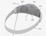
도 2 및 도 3을 참조하면, 전기 자극 장치(100)는 인체의 이마 부위에 전극들이 접촉되도록 착용되는 것으로, 전극부(110)와 고정부(130)를 포함하여 구성될 수 있다.Referring to FIGS. 2 and 3 , the
전극부(110)는, 전기 자극을 가하기 위한 제1 전극(210) 및 제2 전극(220)이 내측면(S)에 구비되고, 제1, 2 전극들(210, 220)이 인체의 이마 부위에 접촉되도록 내측면(S)이 곡면 형상을 가지며, 제1, 2 전극들(210, 220) 사이의 전류 방향과 교차하는 방향으로 자기장을 형성하기 위한 제1 자성체(310) 및 제2 자성체(320)가 내측면(S)에 배치될 수 있다.In the
고정부(130)는 전극부(110)가 이마 부위에 장착되도록 고정하기 위한 것으로서, 밴드 형태로 구성될 수 있으나, 본 발명은 이에 한정되지는 아니한다.The fixing
전기 자극 장치(100)에는, 제1, 2 전극들(210, 220) 사이의 전류와 제1, 2 자성체들(310, 320)에 의해 형성되는 자기장이 서로 교차하는 각도(θ) 또는 제1, 2 자성체들에 의해 형성되는 자기장의 세기(B)를 조절하기 위한 제어부가 포함될 수 있다.In the
예를 들어, 제어부는 교차 각도(θ) 및 자기장의 세기(B) 중 적어도 하나를 조절하기 위한 회로들이 형성된 IC 칩으로 구현되어 전극부(110) 내부에 구비될 수 있으나, 본 발명은 이에 한정되지는 아니한다.For example, the control unit may be implemented as an IC chip having circuits for adjusting at least one of the crossing angle θ and the strength of the magnetic field B, and may be provided inside the
도 4는 본 발명의 일실시예에 따른 제어 장치의 구성에 대한 일실시예를 도시한 것이다.Figure 4 shows an embodiment of the configuration of a control device according to an embodiment of the present invention.
도 4를 참조하면, 제어 장치(500)는 사용자 입력을 수신하기 위한 복수의 버튼들(510)과, 전기 자극 장치(100) 및 제어 장치(500)의 동작 상태를 나타내기 위한 디스플레이(530)를 포함하며, 내부에는 전기 자극 장치(100)의 동작을 제어하기 위한 제어 신호를 생성하는 IC 칩이 구비될 수 있다.Referring to FIG. 4, the
예를 들어, 제어 장치(500)는 전기 자극 장치(100)의 전극부(110)에 연결된 케이블(150)을 이용하여 제어 신호를 전기 자극 장치(100)로 전송할 수 있으나, 전기 자극 장치(100)와 제어 장치(500)는 블루투스(bluetooth) 등과 같은 근거리 무선 통신 기술을 이용하여 신호를 송수신할 수도 있다.For example, the
본 발명의 일실시예에 따르면, 제어 장치(500)는 치료하고자 하는 질환 또는 전기 자극하고자 하는 뇌의 타겟 영역을 사용자로부터 입력받고, 사용자 입력에 대응되는 전류 경로의 깊이를 계산하며, 계산된 전류 경로 깊이를 형성할 수 있도록 하는 교차 각도(θ) 또는 자기장의 세기(B)에 대한 정보를 전기 자극 장치(100)의 전극부(110)에 제어 신호로 전달할 수 있다.According to one embodiment of the present invention, the
한편, 제어 장치(500)로부터 제어 신호를 수신한 전극부(110)는, 내부의 제어부를 구동부를 제어하여, 제어 신호에 포함된 교차 각도(θ)에 따라 제1, 2 자성체들(310, 320)의 위치를 이동시켜 제1, 2 전극들(210, 220) 사이의 전류와 제1, 2 자성체들(310, 320)에 의해 형성되는 자기장이 해당 각도(θ)로 교차되도록 할 수 있다.On the other hand, the
또한, 전극부(110)는, 내부의 제어부가 제1, 2 자성체들(310, 320)로 공급되는 전류 값을 변화시켜, 제1, 2 자성체들(310, 320)에 의해 형성되는 자기장의 세기가 해당 세기(B)를 가지도록 조절할 수 있다.In addition, in the
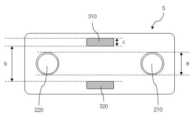
도 5 및 도 6은 전극부의 내측면에 구비되는 전극들과 자성체들의 배치에 대한 일실시예를 설명하기 위해 도시한 것이다.5 and 6 are diagrams for explaining an embodiment of the arrangement of electrodes and magnetic materials provided on the inner surface of the electrode unit.
도 5 및 도 6을 참조하면, 전극부(110)의 내측면(S)에는 사용자의 이마 부위에 접촉되는 제1 전극(210) 및 제2 전극(220)이 배치될 수 있다.Referring to FIGS. 5 and 6 , a
예를 들어, 제1, 2 전극들(210, 220)은 각각 양극과 음극으로 구성되어, 제1, 2 전극들(210, 220) 사이에 흐르는 전류가 이마 표면에 일정 깊이로 전류 경로를 형성하여, 뇌의 특정 부위에 직류 자극을 가할 수 있다.For example, the first and
또한, 전극부(110)의 내측면(S)에는, 제1, 2 전극들(210, 220) 사이의 전류 방향과 교차하는 방향으로 자기장을 형성하기 위한 제1 자성체(310) 및 제2 자성체(320)가 배치될 수 있다.In addition, on the inner surface (S) of the
제1, 2 자성체들(310, 320)은 제1, 2 전극들(210, 220)에 인접하도록 배치되어, 제1, 2 전극들(210, 220) 사이의 전류 경로에 영향을 미쳐, 전류 경로의 변경에 의해 전기 자극이 가해지는 타겟 부위가 조정되도록 할 수 있다.The first and second
예를 들어, 제1, 2 자성체들(310, 320)은 각각 서로 다른 극성을 가지는 영구 자석 또는 전자석으로 구성될 수 있다.For example, the first and second
예를 들어, 도 5에 도시된 바와 같이 제1, 2 전극들인 양극(210)과 음극(220)의 중심을 잇는 제1 선과 제1, 2 자성체들인 N극 자석(310)과 S극 자석(320)의 중심을 잇는 제2 선이 소정의 각도(θ)를 가지고 서로 교차하도록 전극들과 자성체들이 배치될 수 있다.For example, as shown in FIG. 5, a first line connecting the centers of the first and second electrodes, the
그에 따라, 양극(210)과 음극(220) 사이의 전류 방향과 N극 자석(310)과 S극 자석(320)에 의해 형성되는 자기장의 방향이, 소정의 각도(θ)를 가지고 서로 교차될 수 있다.Accordingly, the direction of the current between the
상기한 바와 같이 제1, 2 전극들(210, 220) 사이의 전류 방향과 제1, 2 자성체들(310, 320)에 의한 자기장이 방향이 교차되는 경우, 전류 경로에 가해지는 자기력의 세기는 아래의 표 1과 같이 나타내어 질 수 있다.As described above, when the direction of the current between the first and

표 1에서, L은 전류의 크기, B는 자기장의 세기, θ는 전류의 방향과 자기장의 방향이 교차하는 각도를 의미한다.In Table 1, L is the magnitude of the current, B is the strength of the magnetic field, and θ is the angle at which the direction of the current and the direction of the magnetic field intersect.
즉, 제1, 2 자성체들(310, 320)에 의한 자기장에 의해 제1, 2 전극들(210, 220) 사이 전류 경로에 가해지는 자기력의 세기는, 교차하는 각도(θ)와 자기장의 세기(B)에 의해 변경될 수 있다.That is, the strength of the magnetic force applied to the current path between the first and
구체적으로, 전류와 자기장의 교차 각도(θ)가 90도일 때 자기력의 세기가 가장 크며, 90도에서 0도 또는 180도에 가까워질 수도록 자기력의 세기가 감소될 수 있다.Specifically, the strength of the magnetic force is greatest when the intersection angle (θ) of the current and the magnetic field is 90 degrees, and the strength of the magnetic force can be reduced so as to approach 0 degrees or 180 degrees at 90 degrees.
여기서, 제1, 2 전극들(210, 220) 사이의 전류와 제1, 2 자성체들(310, 320)에 의해 형성되는 자기장이 서로 교차하는 각도(θ)를 조절하기 위해, 제1, 2 자성체들(310, 320)의 위치를 이동시키는 구동부가 전극부(110)에 구비될 수 있다.Here, in order to adjust the angle θ at which the current between the first and
또한, 제1, 2 자성체들(310, 320)에 의해 형성되는 자기장의 세기(B)가 증가될 수록, 전류 경로에 가해지는 자기력의 세기가 증가될 수 있다.In addition, as the strength (B) of the magnetic field formed by the first and second
도 7을 참조하면, 양극(210)과 음극(220) 사이의 전류 경로는 일정 깊이(d)를 가져, 전극들(210, 220)이 접촉된 표면에서 전류 경로에 위치하는 뇌 내부의 특정 부위에 전기 자극을 가할 수 있다.Referring to FIG. 7 , the current path between the
여기서, 상기한 바와 같이 자성체들(310, 320)에 의해 전극들(210, 220) 사이 전류 경로에 가해지는 자기력의 세기가 변경되는 경우, 전극들(210, 220) 사이 전류 경로의 깊이(d)가 조절될 수 있다.Here, when the strength of the magnetic force applied to the current path between the
그에 따라, 제어부는 제1, 2 전극들 사이의 전류와 제1, 2 자성체들에 의해 형성되는 자기장이 서로 교차하는 각도(θ) 또는 제1, 2 자성체들에 의해 형성되는 자기장의 세기(B)를 조절하여, 전극들 사이 전류 경로의 깊이(d)가 조절되도록 할 수 있으며, 전류 경로의 깊이(d)가 조절됨에 따라 전극들(210, 220)이 접촉된 이마 부위로부터 전기 자극되는 뇌 영역까지의 거리가 가변될 수 있다.Accordingly, the controller may determine the angle θ at which the current between the first and second electrodes and the magnetic fields formed by the first and second magnetic bodies cross each other or the strength of the magnetic field formed by the first and second magnetic bodies (B ), the depth d of the current path between the electrodes can be adjusted, and as the depth d of the current path is adjusted, the brain electrically stimulated from the forehead where the
위와 같이 전극들 사이 전류 경로의 깊이(d)가 조절되면, 전기 자극되는 뇌 내부의 타겟 영역이 가변될 수 있으며, 그에 따라 피부 표면에서 더 깊은 전류 경로를 형성하여 뇌 심부에 전기 자극이 가해지도록 하거나, 불필요한 부위에 전기 자극이 가해지는 것을 방지할 수 있다.As above, if the depth (d) of the current path between the electrodes is adjusted, the target area inside the brain to be electrically stimulated can be varied, and accordingly, a deeper current path is formed on the skin surface so that electrical stimulation is applied to the deep brain. Alternatively, electrical stimulation may be prevented from being applied to an unnecessary part.
상기한 바와 같은 본 발명의 일실시예에 따르면, 곡면 형상의 전극부 내측면에 구비된 전극들이 인체의 이마 부위에 접촉되도록 하여 전기 자극이 안정적으로 뇌에 가해지도록 하며, 전극부 내측면에 전극들과 함께 배치된 자성체들을 이용해 전극들 사이의 전류 경로 깊이를 조절함으로써, 전극들이 이마에 접촉된 상태에서도 다양한 깊이의 뇌 타겟 부위들에 전기 자극을 가할 수 있도록 한다.According to one embodiment of the present invention as described above, the electrodes provided on the inner surface of the curved electrode unit are in contact with the forehead portion of the human body so that electrical stimulation is stably applied to the brain, and the electrodes on the inner surface of the electrode unit By adjusting the depth of the current path between the electrodes using magnetic materials disposed together with the electrodes, electrical stimulation can be applied to brain target areas of various depths even when the electrodes are in contact with the forehead.
이하 도 8 내지 도 10을 참조하여, 본 발명에 따른 비침습적 전기 자극 방법에 대한 실시예들을 보다 상세히 설명하기로 한다.Hereinafter, embodiments of the non-invasive electrical stimulation method according to the present invention will be described in more detail with reference to FIGS. 8 to 10 .
도 8은 본 발명에 따른 비침습적 전기 자극 방법에 대한 일실시예를 흐름도로 도시한 것으로, 도시된 방법들 중 도 1 내지 도 7을 참조하여 상기에서 설명한 것과 동일한 것에 대한 설명은 생략하기로 한다.8 is a flowchart illustrating an embodiment of a non-invasive electrical stimulation method according to the present invention, and among the illustrated methods, descriptions of the same as those described above with reference to FIGS. 1 to 7 will be omitted. .
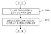
도 8을 참조하면, 전기 자극을 가하기 위한 제1, 2 전극들과 제1, 2 전극들 사이의 전류 방향과 교차하는 방향으로 자기장을 형성하기 위한 제1, 2 자성체들이 내측면에 배치되는 전기 자극 장치(100)의 전극부가 인체의 이마 부위에 장착된다(S800 단계).Referring to FIG. 8, the first and second electrodes for applying electrical stimulation and the first and second magnetic bodies for forming a magnetic field in a direction crossing the current direction between the first and second electrodes are disposed on the inner surface. The electrode part of the
그 후, 제1, 2 전극들 사이의 전류와 제1, 2 자성체들에 의해 형성되는 자기장이 서로 교차하는 각도(θ) 및 제1, 2 자성체들에 의해 형성되는 자기장의 세기(B) 중 적어도 하나가 조절된다(S810 단계).Then, of the angle θ at which the magnetic field formed by the current between the first and second electrodes and the first and second magnetic bodies cross each other and the strength of the magnetic field formed by the first and second magnetic bodies (B) At least one is adjusted (step S810).
예를 들어, 교차 각도(θ) 또는 자기장 세기(B)가 조절되는 S410 단계는, 전기 자극 장치(10)의 동작이 시작되는 시점이나 전기 자극하고자 하는 뇌 타겟 영역이 변경되는 시점, 또는 전기 자극 장치(10)의 캘리브레이션(calibration) 과정에서 수정될 수 있으나, 본 발명은 이에 한정되지는 아니한다.For example, step S410 in which the crossing angle θ or the magnetic field strength B is adjusted is the time at which the operation of the
도 9는 전류와 자기장이 서로 교차하는 각도(θ)를 조절하는 방법에 대한 실시예들을 설명하기 위해 도시한 것이다.9 is a diagram for explaining embodiments of a method for adjusting an angle θ at which a current and a magnetic field cross each other.
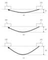
도 9를 참조하면, 전극들(210, 220) 사이의 전류와 자성체들 자기장의 교차 각도(θ)가 (a), (b), (c)의 순으로 증가되고, 도 5의 (c)에서는 교차 각도(θ)가 90도 일 수 있다.Referring to FIG. 9, the intersection angle θ of the current between the
이와 같이, 전류와 자기장의 교차 각도(θ)가 증가되어 90에 가까워질 수록, 전극들(210, 220) 사이 전류 경로의 깊이가 증가된다.As such, as the intersection angle θ of the current and the magnetic field increases and approaches 90, the depth of the current path between the
예를 들어, 제1, 2 자성체들(310, 320)이 각각 N극과 S극의 영구 자석들로 구성된 경우, 전극들(210, 220)의 접촉 위치는 고정한 상태에서 제1, 2 자성체들(310, 320)의 위치를 이동시켜, 제1, 2 전극들(210, 220)의 중심을 잇는 제1 선과 제1, 2 자성체들(310, 320)의 중심을 잇는 제2 선 사이의 각도(θ)가 변경되도록 하며, 이 때 교차 각도(θ)가 90도에 가까워질 수록 제1, 2 전극들(310, 320) 사이 전류 경로의 깊이가 증가될 수 있다.For example, when the first and second
도 10의 (a), (b), (c)는 도 9의 (a), (b), (c)에 도시된 교차 각도(θ)에 각각 대응되는 전류 경로에 대한 예를 나타낸 것으로, 교차 각도(θ)가 증가되어 90도에 가까워질 수록 전류 경로의 깊이가 증가됨을 나타낸다.10 (a), (b), and (c) show examples of current paths respectively corresponding to the crossing angles θ shown in FIG. 9 (a), (b), and (c), As the crossing angle θ increases and approaches 90 degrees, it indicates that the depth of the current path increases.
한편, 제1, 2 자성체들(310, 320)이 전자석으로 구성된 경우에도, 전극들(210, 220)의 접촉 위치는 고정한 상태에서 제1, 2 자성체들(310, 320)의 위치를 이동시켜, 제1, 2 전극들(210, 220)의 중심을 잇는 제1 선과 제1, 2 자성체들(310, 320)의 중심을 잇는 제2 선 사이의 각도(θ)가 변경되도록 하여, 교차 각도(θ)가 90도에 가까워질 수록 제1, 2 전극들(310, 320) 사이 전류 경로의 깊이가 증가되도록 조절할 수 있다.Meanwhile, even when the first and second
상기한 바와 같이 교차 각도(θ)를 조절하여 전류 경로의 깊이가 증가될 수록, 전기 자극되는 타겟 영역이 깊어져, 전극들(210, 220)이 접촉된 이마 부위로부터 보다 멀리 떨어진 뇌 영역에 전기 자극이 가해지도록 할 수 있다.As described above, as the depth of the current path increases by adjusting the crossing angle θ, the target area to be electrically stimulated deepens, and electricity is transmitted to the brain area further away from the forehead where the
한편, 제1, 2 자성체들(310, 320)이 전자석으로 구성된 경우, 전극들(210, 220)의 접촉 위치는 고정한 상태에서 제1, 2 자성체들(310, 320)로 공급되는 전류의 크기를 변경시킴으로써, 제1, 2 전극들(310, 320) 사이 전류 경로의 깊이를 조절할 수 있다.Meanwhile, when the first and second
상기한 바와 같이 제1, 2 자성체들(310, 320)로 공급되는 전류의 크기를 변경시켜 전기장의 세기(B)를 증가시키는 경우에도, 도 10의 (a), (b), (c)에 도시된 바와 같이 제1, 2 전극들(310, 320) 사이 전류 경로의 깊이가 증가될 수 있다.As described above, even when the strength of the electric field (B) is increased by changing the magnitude of the current supplied to the first and second
상기한 바와 같이 제1, 2 자성체들(310, 320)에 의한 자기장 세기(B)를 조절하여 전류 경로의 깊이가 증가될 수록, 전기 자극되는 타겟 영역이 깊어져, 전극들(210, 220)이 접촉된 이마 부위로부터 보다 멀리 떨어진 뇌 영역에 전기 자극이 가해지도록 할 수 있다.As described above, as the depth of the current path increases by adjusting the magnetic field strength B by the first and second
상술한 본 발명의 일실시예에 따른 방법들은 컴퓨터에서 실행되기 위한 프로그램으로 제작될 수 있다. 또한, 상기 프로그램은 컴퓨터가 읽을 수 있는 기록 매체에 저장될 수 있으며, 컴퓨터가 읽을 수 있는 기록 매체의 예로는 ROM, RAM, CD-ROM, 자기 테이프, 플로피디스크, 광 데이터 저장장치 등이 있다.The methods according to one embodiment of the present invention described above may be produced as a program to be executed on a computer. In addition, the program may be stored in a computer-readable recording medium, and examples of the computer-readable recording medium include ROM, RAM, CD-ROM, magnetic tape, floppy disk, optical data storage device, and the like.
컴퓨터가 읽을 수 있는 기록 매체는 네트워크로 연결된 컴퓨터 시스템에 분산되어, 분산방식으로 컴퓨터가 읽을 수 있는 코드가 저장되고 실행될 수 있다. 그리고, 상기 방법을 구현하기 위한 기능적인(function) 프로그램, 코드 및 코드 세그먼트들은 본 발명이 속하는 기술분야의 프로그래머들에 의해 용이하게 추론될 수 있다.The computer-readable recording medium is distributed to computer systems connected through a network, so that computer-readable codes can be stored and executed in a distributed manner. In addition, functional programs, codes, and code segments for implementing the method can be easily inferred by programmers in the technical field to which the present invention belongs.
또한, 이상에서는 본 발명의 바람직한 실시예에 대하여 도시하고 설명하였지만, 본 발명은 상술한 특정의 실시예에 한정되지 아니하며, 청구범위에서 청구하는 본 발명의 요지를 벗어남이 없이 당해 발명이 속하는 기술분야에서 통상의 지식을 가진 자에 의해 다양한 변형 실시가 가능한 것은 물론이고, 이러한 변형 실시들은 본 발명의 기술적 사상이나 전망으로부터 개별적으로 이해되어져서는 안 될 것이다.In addition, although the preferred embodiments of the present invention have been shown and described above, the present invention is not limited to the specific embodiments described above, and the technical field to which the present invention belongs without departing from the gist of the present invention claimed in the claims. Of course, various modifications are possible by those skilled in the art, and these modifications should not be individually understood from the technical spirit or perspective of the present invention.
Claims (10)
Translated fromKorean전기 자극을 가하기 위한 제1 전극 및 제2 전극이 내측면에 구비되어 인체의 이마 부위에 접촉되며, 상기 제1, 2 전극들 사이의 전류 방향과 교차하는 방향으로 자기장을 형성하기 위한 제1 자성체 및 제2 자성체가 상기 내측면에 배치되는 전극부;
상기 제1, 2 전극들 사이의 전류와 상기 제1, 2 자성체들에 의해 형성되는 자기장이 서로 교차하는 각도(θ) 및 상기 제1, 2 자성체들에 의해 형성되는 자기장의 세기(B) 중 적어도 하나를 조절하기 위한 제어부; 및
상기 전극부가 이마 부위에 장착되도록 고정하기 위한 고정부;를 포함하는 비침습적 전기 자극 장치.In the device for non-invasively applying electrical stimulation by contacting electrodes to the human body,
A first electrode and a second electrode for applying electric stimulation are provided on the inner surface to be in contact with the forehead of the human body, and a first magnetic material for forming a magnetic field in a direction crossing the current direction between the first and second electrodes and an electrode unit in which a second magnetic body is disposed on the inner surface.
Among the angle θ at which the current between the first and second electrodes and the magnetic fields formed by the first and second magnetic bodies cross each other and the strength of the magnetic field formed by the first and second magnetic bodies (B) a control unit for controlling at least one; and
Non-invasive electrical stimulation device comprising a; fixing part for fixing the electrode part to be mounted on the forehead.
상기 제1, 2 전극들 사이의 전류와 상기 제1, 2 자성체들에 의해 형성되는 자기장이 서로 교차하는 각도(θ)를 조절하기 위해, 상기 제1, 2 자성체들의 위치를 이동시키는 구동부;를 더 포함하는 비침습적 전기 자극 장치.According to claim 1,
a driving unit that moves the positions of the first and second magnetic bodies to adjust an angle θ at which a current between the first and second electrodes and a magnetic field formed by the first and second magnetic bodies cross each other; A non-invasive electrical stimulation device further comprising.
상기 제1, 2 자성체들이 서로 다른 극성을 가지는 전자석으로 구성된 경우,
상기 제어부는
자기장 형성을 위해 상기 제1, 2 자성체들로의 공급되는 전류의 크기가 변경되도록 제어하는 비침습적 전기 자극 장치.According to claim 1,
When the first and second magnetic bodies are composed of electromagnets having different polarities,
The control unit
Non-invasive electrical stimulation device for controlling the size of the current supplied to the first and second magnetic bodies to form a magnetic field.
상기 교차하는 각도(θ)가 90도에 가까워질 수록, 상기 제1, 2 전극들 사이 전류 경로의 깊이가 증가되어, 상기 전극들이 접촉된 이마 부위로부터 보다 멀리 떨어진 뇌 영역에 전기 자극이 가해지는 비침습적 전기 자극 장치.According to claim 1,
As the crossing angle θ approaches 90 degrees, the depth of the current path between the first and second electrodes increases, so that electrical stimulation is applied to a brain region farther away from the forehead where the electrodes are in contact. Non-invasive electrical stimulation device.
상기 자기장의 세기(B)가 증가될 수록, 상기 제1, 2 전극들 사이 전류 경로의 깊이가 증가되어, 상기 전극들이 접촉된 이마 부위로부터 보다 멀리 떨어진 뇌 영역에 전기 자극이 가해지는 비침습적 전기 자극 장치.According to claim 1,
As the strength of the magnetic field (B) increases, the depth of the current path between the first and second electrodes increases, so that electrical stimulation is applied to a region of the brain farther from the forehead where the electrodes are in contact. stimulation device.
상기 전극부의 내측면에 구비되는 상기 제1, 2 자성체들 사이의 간격은 상기 제1, 2 전극들의 폭 이상으로 설정되는 비침습적 전기 자극 장치.According to claim 1,
The distance between the first and second magnetic bodies provided on the inner surface of the electrode unit is set to be equal to or greater than the width of the first and second electrodes.
전기 자극을 가하기 위한 제1 전극 및 제2 전극과 상기 제1, 2 전극들 사이의 전류 방향과 교차하는 방향으로 자기장을 형성하기 위한 제1 자성체 및 제2 자성체가 내측면에 배치되는 전극부가 인체의 이마 부위에 장착되는 단계; 및
상기 제1, 2 전극들 사이의 전류와 상기 제1, 2 자성체들에 의해 형성되는 자기장이 서로 교차하는 각도(θ) 및 상기 제1, 2 자성체들에 의해 형성되는 자기장의 세기(B) 중 적어도 하나를 조절하는 단계;를 포함하는 비침습적 전기 자극 방법.In the non-invasive electrical stimulation method by contacting electrodes to the human body,
A first electrode and a second electrode for applying electrical stimulation and an electrode unit disposed on an inner surface of a first and second magnetic body for forming a magnetic field in a direction crossing the direction of current between the first and second electrodes Mounting on the forehead of the step; and
Among the angle θ at which the current between the first and second electrodes and the magnetic fields formed by the first and second magnetic bodies cross each other and the strength of the magnetic field formed by the first and second magnetic bodies (B) Controlling at least one; non-invasive electrical stimulation method comprising.
상기 교차하는 각도(θ)가 90도에 가까워질 수록, 상기 제1, 2 전극들 사이 전류 경로의 깊이가 증가되어, 전기 자극되는 타겟 영역이 깊어지는 비침습적 전기 자극 방법.According to claim 7,
As the crossing angle (θ) approaches 90 degrees, the depth of the current path between the first and second electrodes increases, thereby deepening the target region to be electrically stimulated.
상기 자기장의 세기(B)가 증가될 수록, 상기 제1, 2 전극들 사이 전류 경로의 깊이가 증가되어, 전기 자극되는 타겟 영역이 깊어지는 비침습적 전기 자극 방법.According to claim 7,
As the strength of the magnetic field (B) increases, the depth of the current path between the first and second electrodes increases, thereby deepening the target region to be electrically stimulated.
상기 전기 자극 장치의 동작을 제어하기 위한 제어 장치;를 포함하고,
상기 전기 자극 장치는
곡면 형상을 가지는 내측면에 상기 제1, 2 전극들과, 상기 제1, 2 전극들 사이의 전류 방향과 교차하는 방향으로 자기장을 형성하기 위한 제1 자성체 및 제2 자성체가 배치되는 전극부;를 포함하고,
상기 제어 장치는
상기 제1, 2 전극들 사이의 전류와 상기 제1, 2 자성체들에 의해 형성되는 자기장이 서로 교차하는 각도(θ) 및 상기 제1, 2 자성체들에 의해 형성되는 자기장의 세기(B) 중 적어도 하나를 조절하기 위한 제어 신호를 상기 전기 자극 장치의 전극부로 제공하는 비침습적 전기 자극 시스템.An electrical stimulation device having a first electrode and a second electrode for applying electrical stimulation; and
Including; a control device for controlling the operation of the electrical stimulation device;
The electrical stimulation device
an electrode unit in which the first and second electrodes and a first magnetic body and a second magnetic body are disposed on an inner surface having a curved shape to form a magnetic field in a direction crossing a current direction between the first and second electrodes; including,
The control device
Among the angle θ at which the current between the first and second electrodes and the magnetic fields formed by the first and second magnetic bodies cross each other and the strength of the magnetic field formed by the first and second magnetic bodies (B) A non-invasive electrical stimulation system for providing a control signal for adjusting at least one of the electrodes of the electrical stimulation device.
Priority Applications (5)
| Application Number | Priority Date | Filing Date | Title |
|---|---|---|---|
| KR1020210164543AKR20230077354A (en) | 2021-11-25 | 2021-11-25 | Noninvasive electrical stimulation device having magnets, method and system for electrical stimulation |
| PCT/KR2021/018917WO2023075014A1 (en) | 2021-10-29 | 2021-12-14 | Non-invasive electrical stimulation method and device |
| CN202180095643.7ACN117042837A (en) | 2021-10-29 | 2021-12-14 | Non-invasive electrical stimulation method and apparatus |
| US17/645,297US20230139236A1 (en) | 2021-10-29 | 2021-12-20 | Noninvasive electrical stimulation method and device |
| KR1020240065511AKR20240081455A (en) | 2021-11-25 | 2024-05-21 | Noninvasive electrical stimulation device having magnets, method and system for electrical stimulation |
Applications Claiming Priority (1)
| Application Number | Priority Date | Filing Date | Title |
|---|---|---|---|
| KR1020210164543AKR20230077354A (en) | 2021-11-25 | 2021-11-25 | Noninvasive electrical stimulation device having magnets, method and system for electrical stimulation |
Related Child Applications (1)
| Application Number | Title | Priority Date | Filing Date |
|---|---|---|---|
| KR1020240065511ADivisionKR20240081455A (en) | 2021-11-25 | 2024-05-21 | Noninvasive electrical stimulation device having magnets, method and system for electrical stimulation |
Publications (1)
| Publication Number | Publication Date |
|---|---|
| KR20230077354Atrue KR20230077354A (en) | 2023-06-01 |
Family
ID=86770616
Family Applications (2)
| Application Number | Title | Priority Date | Filing Date |
|---|---|---|---|
| KR1020210164543ACeasedKR20230077354A (en) | 2021-10-29 | 2021-11-25 | Noninvasive electrical stimulation device having magnets, method and system for electrical stimulation |
| KR1020240065511APendingKR20240081455A (en) | 2021-11-25 | 2024-05-21 | Noninvasive electrical stimulation device having magnets, method and system for electrical stimulation |
Family Applications After (1)
| Application Number | Title | Priority Date | Filing Date |
|---|---|---|---|
| KR1020240065511APendingKR20240081455A (en) | 2021-11-25 | 2024-05-21 | Noninvasive electrical stimulation device having magnets, method and system for electrical stimulation |
Country Status (2)
| Country | Link |
|---|---|
| KR (2) | KR20230077354A (en) |
| CN (1) | CN117042837A (en) |
Cited By (1)
| Publication number | Priority date | Publication date | Assignee | Title |
|---|---|---|---|---|
| KR20250046811A (en) | 2023-09-27 | 2025-04-03 | 한국광기술원 | Near-infrared and ultrasound-based non-invasive treatment device for migraine relief |
Families Citing this family (1)
| Publication number | Priority date | Publication date | Assignee | Title |
|---|---|---|---|---|
| KR102778290B1 (en)* | 2024-06-24 | 2025-03-10 | (주)비스토스 | brain stimulating apparutus using both electric field and magnetic field |
Citations (1)
| Publication number | Priority date | Publication date | Assignee | Title |
|---|---|---|---|---|
| KR102130198B1 (en) | 2018-02-12 | 2020-07-03 | 부산대학교 산학협력단 | Transcranial direct current stimulation device including needle-like electrode |
- 2021
- 2021-11-25KRKR1020210164543Apatent/KR20230077354A/ennot_activeCeased
- 2021-12-14CNCN202180095643.7Apatent/CN117042837A/enactivePending
- 2024
- 2024-05-21KRKR1020240065511Apatent/KR20240081455A/enactivePending
Patent Citations (1)
| Publication number | Priority date | Publication date | Assignee | Title |
|---|---|---|---|---|
| KR102130198B1 (en) | 2018-02-12 | 2020-07-03 | 부산대학교 산학협력단 | Transcranial direct current stimulation device including needle-like electrode |
Cited By (1)
| Publication number | Priority date | Publication date | Assignee | Title |
|---|---|---|---|---|
| KR20250046811A (en) | 2023-09-27 | 2025-04-03 | 한국광기술원 | Near-infrared and ultrasound-based non-invasive treatment device for migraine relief |
Also Published As
| Publication number | Publication date |
|---|---|
| KR20240081455A (en) | 2024-06-07 |
| CN117042837A (en) | 2023-11-10 |
Similar Documents
| Publication | Publication Date | Title |
|---|---|---|
| US12350504B2 (en) | System and method for transcranial current loop brain stimulation | |
| US8880173B2 (en) | Device for providing transdermal electrical stimulation at an adjustable position on a head | |
| US9066845B2 (en) | Electrode configuration for an implantable electroacupuncture device | |
| KR20240081455A (en) | Noninvasive electrical stimulation device having magnets, method and system for electrical stimulation | |
| JP2010533023A (en) | Nerve stimulation system | |
| US9421377B2 (en) | Apparatus, method and system for closed-loop neurostimulation | |
| US20050246003A1 (en) | Stimulation lead having pairs of stimulating electrodes spaced at different distances for providing electrical stimulation to different nerve tissues | |
| AU2020256199B2 (en) | Device and method for wireless microstimulation | |
| US20230139236A1 (en) | Noninvasive electrical stimulation method and device | |
| KR20250133257A (en) | transcutaneous electric stimulation device including a plurality of electrodes | |
| US11458317B1 (en) | Variable amplitude signals for neurological therapy, and associated systems and methods | |
| KR20230061704A (en) | Method and apparatus for noninvasive electrical stimulation | |
| US20060041284A1 (en) | Electrical stimulation system and method for stimulating nerve tissue in the brain using a stimulation lead having a tip electrode, having at least five electrodes, or both | |
| US20210283413A1 (en) | Stimulation of subcortical brain regions using transcranial rotating permanent magnetic stimulation (trpms) | |
| KR20230078120A (en) | Control method of complex stimulation and complex stimulation device | |
| KR102654987B1 (en) | knee microcurrent stimulation device | |
| Madhavan | Magnetic and direct current stimulation for stroke | |
| US20250176903A1 (en) | Wearable Energy Stimulation System For Mammals Targeting The Vagus Nerve, Includes Electrical And Haptic Energy Emitters, A Collar Coupling Apparatus, Energy-Emitter Positioning Circuits, And Position Maintenance And Verification Means, Multi-Modal Operation, Energy-Emitter Modularization, And Closed Loop Configuration | |
| RU2770272C1 (en) | Device for transcranial stimulation of the brain by pulsating current | |
| KR20250120019A (en) | Magnetic-stimulation guide device | |
| US10821287B2 (en) | Bioelectrical modulation using rotating or spatially-selective electromagnetic fields | |
| KR20250008196A (en) | Combined electromagnetic neuro-modulation method and device | |
| CN119587874A (en) | Stimulator, medical system and computer readable storage medium | |
| KR20220095813A (en) | Apparatus for Stimulating Brain Nerve |
Legal Events
| Date | Code | Title | Description |
|---|---|---|---|
| PA0109 | Patent application | St.27 status event code:A-0-1-A10-A12-nap-PA0109 | |
| PA0201 | Request for examination | St.27 status event code:A-1-2-D10-D11-exm-PA0201 | |
| PG1501 | Laying open of application | St.27 status event code:A-1-1-Q10-Q12-nap-PG1501 | |
| E902 | Notification of reason for refusal | ||
| PE0902 | Notice of grounds for rejection | St.27 status event code:A-1-2-D10-D21-exm-PE0902 | |
| P11-X000 | Amendment of application requested | St.27 status event code:A-2-2-P10-P11-nap-X000 | |
| P13-X000 | Application amended | St.27 status event code:A-2-2-P10-P13-nap-X000 | |
| E601 | Decision to refuse application | ||
| PE0601 | Decision on rejection of patent | St.27 status event code:N-2-6-B10-B15-exm-PE0601 | |
| PA0107 | Divisional application | St.27 status event code:A-0-1-A10-A18-div-PA0107 St.27 status event code:A-0-1-A10-A16-div-PA0107 | |
| E13-X000 | Pre-grant limitation requested | St.27 status event code:A-2-3-E10-E13-lim-X000 | |
| P11-X000 | Amendment of application requested | St.27 status event code:A-2-2-P10-P11-nap-X000 | |
| P13-X000 | Application amended | St.27 status event code:A-2-2-P10-P13-nap-X000 | |
| PX0901 | Re-examination | St.27 status event code:A-2-3-E10-E12-rex-PX0901 | |
| PX0601 | Decision of rejection after re-examination | St.27 status event code:N-2-6-B10-B17-rex-PX0601 | |
| X601 | Decision of rejection after re-examination |