KR20230075122A - Vehicle seat for sensing bio-signal - Google Patents
Vehicle seat for sensing bio-signalDownload PDFInfo
- Publication number
- KR20230075122A KR20230075122AKR1020210161402AKR20210161402AKR20230075122AKR 20230075122 AKR20230075122 AKR 20230075122AKR 1020210161402 AKR1020210161402 AKR 1020210161402AKR 20210161402 AKR20210161402 AKR 20210161402AKR 20230075122 AKR20230075122 AKR 20230075122A
- Authority
- KR
- South Korea
- Prior art keywords
- signal
- driver
- piezoelectric sensor
- biosignal
- contact
- Prior art date
- Legal status (The legal status is an assumption and is not a legal conclusion. Google has not performed a legal analysis and makes no representation as to the accuracy of the status listed.)
- Granted
Links
- 238000007781pre-processingMethods0.000claimsdescription20
- 239000000284extractSubstances0.000claimsdescription13
- 230000037007arousalEffects0.000claimsdescription12
- 230000036387respiratory rateEffects0.000claimsdescription8
- 238000001914filtrationMethods0.000claimsdescription6
- 238000012805post-processingMethods0.000claimsdescription4
- 238000001514detection methodMethods0.000claims3
- 238000010586diagramMethods0.000description13
- 238000000034methodMethods0.000description10
- 230000000694effectsEffects0.000description7
- 230000008569processEffects0.000description5
- 230000008901benefitEffects0.000description4
- UCLKLGIYGBLTSM-UHFFFAOYSA-N1,2,3,4-tetrachloro-5-(2,5-dichlorophenyl)benzeneChemical compoundClC1=CC=C(Cl)C(C=2C(=C(Cl)C(Cl)=C(Cl)C=2)Cl)=C1UCLKLGIYGBLTSM-UHFFFAOYSA-N0.000description3
- 238000005516engineering processMethods0.000description3
- 230000035945sensitivityEffects0.000description3
- 238000013461designMethods0.000description2
- 230000014509gene expressionEffects0.000description2
- 238000012545processingMethods0.000description2
- 230000000241respiratory effectEffects0.000description2
- 230000029058respiratory gaseous exchangeEffects0.000description2
- WDLTVNWWEZJMPF-UHFFFAOYSA-N1,2,3,5-tetrachloro-4-(2,3-dichlorophenyl)benzeneChemical compoundClC1=CC=CC(C=2C(=C(Cl)C(Cl)=CC=2Cl)Cl)=C1ClWDLTVNWWEZJMPF-UHFFFAOYSA-N0.000description1
- 239000002033PVDF binderSubstances0.000description1
- 238000003491arrayMethods0.000description1
- 244000309466calfSpecies0.000description1
- 230000008859changeEffects0.000description1
- 238000006243chemical reactionMethods0.000description1
- 230000005611electricityEffects0.000description1
- 238000000605extractionMethods0.000description1
- 238000009499grossingMethods0.000description1
- 239000000463materialSubstances0.000description1
- 238000005259measurementMethods0.000description1
- 238000012986modificationMethods0.000description1
- 230000004048modificationEffects0.000description1
- 230000004044responseEffects0.000description1
- 238000007650screen-printingMethods0.000description1
- 239000000758substrateSubstances0.000description1
- 230000001131transforming effectEffects0.000description1
Images


Classifications
- B—PERFORMING OPERATIONS; TRANSPORTING
- B60—VEHICLES IN GENERAL
- B60N—SEATS SPECIALLY ADAPTED FOR VEHICLES; VEHICLE PASSENGER ACCOMMODATION NOT OTHERWISE PROVIDED FOR
- B60N2/00—Seats specially adapted for vehicles; Arrangement or mounting of seats in vehicles
- B60N2/002—Seats provided with an occupancy detection means mounted therein or thereon
- B60N2/0021—Seats provided with an occupancy detection means mounted therein or thereon characterised by the type of sensor or measurement
- B60N2/0024—Seats provided with an occupancy detection means mounted therein or thereon characterised by the type of sensor or measurement for identifying, categorising or investigation of the occupant or object on the seat
- B60N2/0027—Seats provided with an occupancy detection means mounted therein or thereon characterised by the type of sensor or measurement for identifying, categorising or investigation of the occupant or object on the seat for detecting the position of the occupant or of occupant's body part
- A—HUMAN NECESSITIES
- A61—MEDICAL OR VETERINARY SCIENCE; HYGIENE
- A61B—DIAGNOSIS; SURGERY; IDENTIFICATION
- A61B5/00—Measuring for diagnostic purposes; Identification of persons
- A61B5/08—Measuring devices for evaluating the respiratory organs
- A61B5/0816—Measuring devices for examining respiratory frequency
- A—HUMAN NECESSITIES
- A61—MEDICAL OR VETERINARY SCIENCE; HYGIENE
- A61B—DIAGNOSIS; SURGERY; IDENTIFICATION
- A61B5/00—Measuring for diagnostic purposes; Identification of persons
- A61B5/103—Measuring devices for testing the shape, pattern, colour, size or movement of the body or parts thereof, for diagnostic purposes
- A61B5/11—Measuring movement of the entire body or parts thereof, e.g. head or hand tremor or mobility of a limb
- A61B5/113—Measuring movement of the entire body or parts thereof, e.g. head or hand tremor or mobility of a limb occurring during breathing
- A61B5/1135—Measuring movement of the entire body or parts thereof, e.g. head or hand tremor or mobility of a limb occurring during breathing by monitoring thoracic expansion
- A—HUMAN NECESSITIES
- A61—MEDICAL OR VETERINARY SCIENCE; HYGIENE
- A61B—DIAGNOSIS; SURGERY; IDENTIFICATION
- A61B5/00—Measuring for diagnostic purposes; Identification of persons
- A61B5/68—Arrangements of detecting, measuring or recording means, e.g. sensors, in relation to patient
- A61B5/6887—Arrangements of detecting, measuring or recording means, e.g. sensors, in relation to patient mounted on external non-worn devices, e.g. non-medical devices
- A61B5/6893—Cars
- A—HUMAN NECESSITIES
- A61—MEDICAL OR VETERINARY SCIENCE; HYGIENE
- A61B—DIAGNOSIS; SURGERY; IDENTIFICATION
- A61B5/00—Measuring for diagnostic purposes; Identification of persons
- A61B5/72—Signal processing specially adapted for physiological signals or for diagnostic purposes
- A61B5/7203—Signal processing specially adapted for physiological signals or for diagnostic purposes for noise prevention, reduction or removal
- B—PERFORMING OPERATIONS; TRANSPORTING
- B60—VEHICLES IN GENERAL
- B60N—SEATS SPECIALLY ADAPTED FOR VEHICLES; VEHICLE PASSENGER ACCOMMODATION NOT OTHERWISE PROVIDED FOR
- B60N2/00—Seats specially adapted for vehicles; Arrangement or mounting of seats in vehicles
- B60N2/02—Seats specially adapted for vehicles; Arrangement or mounting of seats in vehicles the seat or part thereof being movable, e.g. adjustable
- B60N2/0224—Non-manual adjustments, e.g. with electrical operation
- B60N2/0244—Non-manual adjustments, e.g. with electrical operation with logic circuits
- B60N2/0268—Non-manual adjustments, e.g. with electrical operation with logic circuits using sensors or detectors for adapting the seat or seat part, e.g. to the position of an occupant
- A—HUMAN NECESSITIES
- A61—MEDICAL OR VETERINARY SCIENCE; HYGIENE
- A61B—DIAGNOSIS; SURGERY; IDENTIFICATION
- A61B2503/00—Evaluating a particular growth phase or type of persons or animals
- A61B2503/20—Workers
- A61B2503/22—Motor vehicles operators, e.g. drivers, pilots, captains
- B60N2002/0268—
- B—PERFORMING OPERATIONS; TRANSPORTING
- B60—VEHICLES IN GENERAL
- B60N—SEATS SPECIALLY ADAPTED FOR VEHICLES; VEHICLE PASSENGER ACCOMMODATION NOT OTHERWISE PROVIDED FOR
- B60N2210/00—Sensor types, e.g. for passenger detection systems or for controlling seats
- B60N2210/40—Force or pressure sensors
- B60N2210/48—Piezoelectric
Landscapes
- Health & Medical Sciences (AREA)
- Life Sciences & Earth Sciences (AREA)
- Engineering & Computer Science (AREA)
- Public Health (AREA)
- Molecular Biology (AREA)
- Veterinary Medicine (AREA)
- General Health & Medical Sciences (AREA)
- Physics & Mathematics (AREA)
- Animal Behavior & Ethology (AREA)
- Biophysics (AREA)
- Pathology (AREA)
- Biomedical Technology (AREA)
- Heart & Thoracic Surgery (AREA)
- Medical Informatics (AREA)
- Surgery (AREA)
- Physiology (AREA)
- Pulmonology (AREA)
- Signal Processing (AREA)
- Mechanical Engineering (AREA)
- Transportation (AREA)
- Aviation & Aerospace Engineering (AREA)
- Dentistry (AREA)
- Oral & Maxillofacial Surgery (AREA)
- Artificial Intelligence (AREA)
- Computer Vision & Pattern Recognition (AREA)
- Psychiatry (AREA)
- Seats For Vehicles (AREA)
Abstract
Description
Translated fromKorean본 발명은 운전자의 신체와 맞닿는 위치에 배치되는 제1 압전센서와, 운전자의 신체와 맞닿지 않는 위치에 배치되는 제2 압전센서를 이용하여 생체신호를 감지하는 차량 시트에 관한 것이다.The present invention relates to a vehicle seat that detects a biosignal by using a first piezoelectric sensor disposed at a position in contact with the driver's body and a second piezoelectric sensor disposed at a position not in contact with the driver's body.
자율주행 차량에 대한 개발이 지속적으로 이루어지고 있는 시점에서, 운전자의 안전을 보장하기 위한 기술 중 하나는 운전자의 상태를 모니터링하고, 운전자의 상태에 따라 위험도를 평가하여 그에 맞는 조치를 취하는 것이다.At a time when autonomous vehicles are continuously being developed, one of the technologies for ensuring the driver's safety is to monitor the driver's condition, evaluate the degree of risk according to the driver's condition, and take appropriate measures.
운전자의 상태를 모니터링 하기 위해 운전자의 생체신호를 취득하는 다양한 기술이 연구되고 있으며, 이 중 차량 시트에 센서를 설치하여 운전자의 신체에서 발생하는 물리력을 측정하는 방식이 개발되고 있다.In order to monitor the driver's condition, various technologies for obtaining driver's bio-signals are being researched, and among them, a method of measuring physical force generated from the driver's body by installing a sensor on a vehicle seat is being developed.
그러나 종래 센싱 방법에 의하면 측정 정확도를 높이기 위해서는 민감도가 높은 센서를 이용해야 하는데, 민감도가 높은 센서를 이용하는 경우 노이즈도 높은 민감도로 측정됨에 따라 생체신호만을 선택적으로 분리하기 어려운 문제가 있다.However, according to the conventional sensing method, a sensor with high sensitivity should be used to increase measurement accuracy. When using a sensor with high sensitivity, noise is also measured with high sensitivity, making it difficult to selectively separate only biosignals.
또한, 주행 중 차량 시트에는 엔진에서 발생하는 진동, 노면에서 발생하는 진동, 차량 내부에 인가되는 관성 등 여러 요인에 의한 노이즈가 발생하므로, 물리력 측정 센서를 이용하는 경우 생체신호의 취득이 매우 어렵다는 문제가 있다.In addition, noise caused by various factors such as vibration from the engine, vibration from the road surface, and inertia applied to the inside of the vehicle is generated in the vehicle seat while driving. there is.
본 발명은 운전자의 신체와 맞닿는 압전센서에서 취득된 신호와 운전자의 신체와 맞닿지 않는 압전센서에서 취득된 신호의 차이에 기초하여 운전자의 생체신호를 추출하는 차량 시트를 제공하는 것을 목적으로 한다.An object of the present invention is to provide a vehicle seat that extracts a driver's biosignal based on a difference between a signal obtained from a piezoelectric sensor that comes into contact with the driver's body and a signal obtained from a piezoelectric sensor that does not come into contact with the driver's body.
본 발명의 목적들은 이상에서 언급한 목적으로 제한되지 않으며, 언급되지 않은 본 발명의 다른 목적 및 장점들은 하기의 설명에 의해서 이해될 수 있고, 본 발명의 실시예에 의해 보다 분명하게 이해될 것이다. 또한, 본 발명의 목적 및 장점들은 특허 청구 범위에 나타낸 수단 및 그 조합에 의해 실현될 수 있음을 쉽게 알 수 있을 것이다.The objects of the present invention are not limited to the above-mentioned objects, and other objects and advantages of the present invention not mentioned above can be understood by the following description and will be more clearly understood by the examples of the present invention. It will also be readily apparent that the objects and advantages of the present invention may be realized by means of the instrumentalities and combinations indicated in the claims.
전술한 목적을 달성하기 위한 본 발명의 일 실시예에 따른 생체신호 감지를 위한 차량 시트는 착석한 운전자의 생체신호를 감지하기 위한 차량 시트에 있어서, 상기 운전자의 신체와 맞닿는 위치에 배치되는 제1 압전센서, 상기 운전자의 신체와 맞닿지 않는 위치에 배치되는 제2 압전센서 및 상기 제1 및 제2 압전센서에서 취득된 신호에 기초하여 상기 생체신호를 추출하는 프로세서를 포함하는 것을 특징으로 한다.In order to achieve the above object, a vehicle seat for detecting biosignals according to an embodiment of the present invention is a vehicle seat for detecting biosignals of a seated driver, wherein a first portion is disposed at a position in contact with the driver's body. and a piezoelectric sensor, a second piezoelectric sensor disposed at a position not in contact with the driver's body, and a processor extracting the biosignal based on signals obtained from the first and second piezoelectric sensors.
일 실시예에서, 상기 제1 압전센서는 상기 운전자의 신체와 맞닿도록 시트쿠션의 상면에 배치되는 것을 특징으로 한다.In one embodiment, the first piezoelectric sensor is characterized in that it is disposed on the upper surface of the seat cushion to come into contact with the body of the driver.
일 실시예에서, 상기 제1 압전센서는 상기 운전자의 신체와 맞닿도록 등받이의 전면에 배치되는 것을 특징으로 한다.In one embodiment, the first piezoelectric sensor is characterized in that it is disposed on the front surface of the backrest to come into contact with the body of the driver.
일 실시예에서, 상기 제2 압전센서는 상기 운전자의 신체와 맞닿지 않도록 시트쿠션의 측면에 배치되는 것을 특징으로 한다.In one embodiment, the second piezoelectric sensor is characterized in that it is disposed on the side of the seat cushion so as not to come into contact with the body of the driver.
일 실시예에서, 상기 제2 압전센서는 상기 운전자의 신체와 맞닿지 않도록 등받이의 측면에 배치되는 것을 특징으로 한다.In one embodiment, the second piezoelectric sensor is characterized in that it is disposed on the side of the backrest so as not to come into contact with the body of the driver.
일 실시예에서, 상기 제1 및 제2 압전센서는 동일한 구조를 갖는 것을 특징으로 한다.In one embodiment, the first and second piezoelectric sensors are characterized in that they have the same structure.
일 실시예에서, 상기 프로세서는 상기 제1 압전센서에서 취득된 신호에서 상기 제2 압전센서에서 취득된 신호를 감산한 신호 차이를 생체신호로 추출하는 것을 특징으로 한다.In one embodiment, the processor is characterized in that the signal obtained by subtracting the signal obtained from the second piezoelectric sensor from the signal obtained from the first piezoelectric sensor extracts a signal difference as a biosignal.
일 실시예에서, 상기 제1 및 제2 압전센서에서 출력되는 각 신호를 증폭하는 전처리 회로부와, 상기 증폭된 각 신호를 디지털 신호로 변환하여 신호 데이터를 각각 생성하고 상기 신호 데이터를 시계열적인 값으로 출력하는 신호 획득부를 더 포함하고, 상기 프로세서는 각 신호 데이터의 차이에 기초하여 생체신호를 추출하는 것을 특징으로 한다.In one embodiment, a pre-processing circuit unit for amplifying each signal output from the first and second piezoelectric sensors, converting each amplified signal into a digital signal to generate signal data, and converting the signal data into time-series values It further includes a signal acquisition unit that outputs, and the processor extracts a biosignal based on a difference between each signal data.
일 실시예에서, 상기 프로세서는 상기 생체신호에 대해 필터링 전처리를 수행하고, 상기 전처리된 생체신호의 표준편차를 이용하여 각성 구간을 결정하고, 상기 각성 구간이 제거된 생체신호에 대하여 필터링 후처리를 수행하고, 상기 후처리된 생체신호에 푸리에 변환을 적용하여 호흡률을 산출하는 것을 특징으로 한다.In one embodiment, the processor performs filtering preprocessing on the biosignal, determines an arousal interval using a standard deviation of the preprocessed biosignal, and performs filtering postprocessing on the biosignal from which the arousal interval is removed. and calculating a respiratory rate by applying a Fourier transform to the post-processed biosignal.
본 발명은 운전자의 신체와 맞닿는 압전센서에서 취득된 신호와 운전자의 신체와 맞닿지 않는 압전센서에서 취득된 신호의 차이에 기초하여 운전자의 생체신호를 추출함으로써, 차량에서 발생하는 노이즈를 효과적으로 제거하여 생체신호만을 선택적으로 분리할 수 있는 효과가 있다.The present invention extracts a driver's biosignal based on a difference between a signal acquired from a piezoelectric sensor that comes in contact with the driver's body and a signal acquired from a piezoelectric sensor that does not come into contact with the driver's body, thereby effectively removing noise generated from the vehicle. There is an effect of selectively separating only biosignals.
상술한 효과와 더불어 본 발명의 구체적인 효과는 이하 발명을 실시하기 위한 구체적인 사항을 설명하면서 함께 기술한다.In addition to the effects described above, specific effects of the present invention will be described together while explaining specific details for carrying out the present invention.
도 1은 본 발명의 일 실시예에 따른 차량 시트의 구성요소를 도시한 도면.
도 2a 및 도 2b는 차량 시트에 제1 및 제2 압전센서가 배치된 모습의 각 예시를 도시한 도면.
도 3 및 도 4는 제1 및 제2 압전센서의 일 구현예를 도시한 도면.
도 5는 제1 및 제2 압전센서에서 각각 취득된 신호와 이들의 신호 차이를 도시한 도면.
도 6은 도 1에 도시된 각 구성요소의 연결관계를 도시한 도면.
도 7은 전처리 회로부 및 신호 획득부의 일 구현예를 도시한 도면.
도 8은 운전자의 호흡률을 검출하기 위한 프로세스의 일 예시를 도시한 도면.
도 9는 도 8에 도시된 프로세스에 따라 각성 구간을 결정하는 방법을 설명하기 위한 도면.
도 10은 도 6에 도시된 신호 차이를 푸리에 변환한 그래프를 도시한 도면.1 is a view showing components of a vehicle seat according to an embodiment of the present invention.
2A and 2B are diagrams illustrating each example of a state in which first and second piezoelectric sensors are disposed on a vehicle seat;
3 and 4 are diagrams illustrating an implementation example of first and second piezoelectric sensors.
5 is a diagram showing signals obtained from first and second piezoelectric sensors, respectively, and differences between these signals;
Figure 6 is a diagram showing the connection relationship of each component shown in Figure 1;
7 is a diagram showing an implementation example of a pre-processing circuit unit and a signal acquisition unit;
8 illustrates one example of a process for detecting a driver's breathing rate.
9 is a diagram for explaining a method of determining an arousal section according to the process shown in FIG. 8;
FIG. 10 is a graph showing a Fourier-transformed graph of the signal difference shown in FIG. 6;
전술한 목적, 특징 및 장점은 첨부된 도면을 참조하여 상세하게 후술되며, 이에 따라 본 발명이 속하는 기술분야에서 통상의 지식을 가진 자가 본 발명의 기술적 사상을 용이하게 실시할 수 있을 것이다. 본 발명을 설명함에 있어서 본 발명과 관련된 공지 기술에 대한 구체적인 설명이 본 발명의 요지를 불필요하게 흐릴 수 있다고 판단되는 경우에는 상세한 설명을 생략한다. 이하, 첨부된 도면을 참조하여 본 발명에 따른 바람직한 실시예를 상세히 설명하기로 한다. 도면에서 동일한 참조부호는 동일 또는 유사한 구성요소를 가리키는 것으로 사용된다.The above objects, features and advantages will be described later in detail with reference to the accompanying drawings, and accordingly, those skilled in the art to which the present invention belongs will be able to easily implement the technical spirit of the present invention. In describing the present invention, if it is determined that the detailed description of the known technology related to the present invention may unnecessarily obscure the subject matter of the present invention, the detailed description will be omitted. Hereinafter, preferred embodiments according to the present invention will be described in detail with reference to the accompanying drawings. In the drawings, the same reference numerals are used to indicate the same or similar components.
본 명세서에서 제1, 제2 등이 다양한 구성요소들을 서술하기 위해서 사용되나, 이들 구성요소들은 이들 용어에 의해 제한되지 않음은 물론이다. 이들 용어들은 단지 하나의 구성요소를 다른 구성요소와 구별하기 위하여 사용하는 것으로, 특별히 반대되는 기재가 없는 한, 제1 구성요소는 제2 구성요소일 수도 있음은 물론이다.In this specification, first, second, etc. are used to describe various components, but these components are not limited by these terms, of course. These terms are only used to distinguish one component from another component, and unless otherwise stated, the first component may be the second component, of course.
또한, 본 명세서에서 "상부 (또는 하부)" 또는 구성요소의 "상 (또는 하)"에 임의의 구성이 배치된다는 것은, 임의의 구성이 상기 구성요소의 상면 (또는 하면)에 접하여 배치되는 것뿐만 아니라, 상기 구성요소와 상기 구성요소 상에 (또는 하에) 배치된 임의의 구성 사이에 다른 구성이 개재될 수 있음을 의미할 수 있다.In addition, in the present specification, "upper (or lower)" or "upper (or lower)" of a component means that an arbitrary component is disposed in contact with the upper (or lower) surface of the component. In addition, it may mean that other components may be interposed between the component and any component disposed on (or under) the component.
또한, 본 명세서에서 어떤 구성요소가 다른 구성요소에 "연결", "결합" 또는 "접속"된다고 기재된 경우, 상기 구성요소들은 서로 직접적으로 연결되거나 또는 접속될 수 있지만, 각 구성요소 사이에 다른 구성요소가 "개재"되거나, 각 구성요소가 다른 구성요소를 통해 "연결", "결합" 또는 "접속"될 수도 있는 것으로 이해되어야 할 것이다.In addition, in the present specification, when a component is described as being “connected”, “coupled” or “connected” to another component, the components may be directly connected or connected to each other, but other components may be present between each component. It should be understood that elements may be “interposed,” or that each element may be “connected,” “coupled,” or “connected” through other elements.
또한, 본 명세서에서 사용되는 단수의 표현은 문맥상 명백하게 다르게 뜻하지 않는 한, 복수의 표현을 포함한다. 본 출원에서, "구성된다" 또는 "포함한다" 등의 용어는 명세서 상에 기재된 여러 구성 요소들, 또는 여러 단계들을 반드시 모두 포함하는 것으로 해석되지 않아야 하며, 그 중 일부 구성 요소들 또는 일부 단계들은 포함되지 않을 수도 있고, 또는 추가적인 구성 요소 또는 단계들을 더 포함할 수 있는 것으로 해석되어야 한다.Also, singular expressions used in this specification include plural expressions unless the context clearly indicates otherwise. In this application, terms such as "consisting of" or "comprising" should not be construed as necessarily including all of the various components or steps described in the specification, and some of the components or some of the steps It should be construed that it may not be included, or may further include additional components or steps.
또한, 본 명세서에서, "A 및/또는 B" 라고 할 때, 이는 특별한 반대되는 기재가 없는 한, A, B 또는 A 및 B 를 의미하며, "C 내지 D" 라고 할 때, 이는 특별한 반대되는 기재가 없는 한, C 이상이고 D 이하인 것을 의미한다In addition, in the present specification, when "A and / or B", unless otherwise specified, it means A, B or A and B, and when "C to D", it means a special opposite Unless otherwise specified, it means more than C and less than D
본 발명은 착석한 운전자의 생체신호를 감지하기 위한 차량 시트에 관한 것으로, 보다 구체적으로 운전자의 신체와 맞닿는 위치에 배치되는 제1 압전센서와, 운전자의 신체와 맞닿지 않는 위치에 배치되는 제2 압전센서를 이용하여 생체신호를 감지하는 차량 시트에 관한 것이다. 이하, 도 1 내지 도 10을 참조하여 본 발명의 일 실시예에 따른 차량 시트를 구체적으로 설명하도록 한다.The present invention relates to a vehicle seat for sensing a biosignal of a seated driver, and more particularly, a first piezoelectric sensor disposed at a position in contact with the driver's body, and a second piezoelectric sensor disposed at a position not in contact with the driver's body. It relates to a vehicle seat that senses a biosignal using a piezoelectric sensor. Hereinafter, a vehicle seat according to an embodiment of the present invention will be described in detail with reference to FIGS. 1 to 10 .
도 1은 본 발명의 일 실시예에 따른 차량 시트의 구성요소를 도시한 도면이다.1 is a view showing components of a vehicle seat according to an embodiment of the present invention.
도 2a 및 도 2b는 차량 시트에 제1 및 제2 압전센서가 배치된 모습의 각 예시를 도시한 도면이다.2A and 2B are diagrams illustrating each example of a state in which first and second piezoelectric sensors are disposed on a vehicle seat.
도 3 및 도 4는 제1 및 제2 압전센서의 일 구현예를 도시한 도면이고, 도 5는 제1 및 제2 압전센서에서 각각 취득된 신호와 이들의 신호 차이를 도시한 도면이다.3 and 4 are diagrams illustrating an implementation example of the first and second piezoelectric sensors, and FIG. 5 is a diagram illustrating signals obtained from the first and second piezoelectric sensors and differences between the signals.
도 6은 도 1에 도시된 각 구성요소의 연결관계를 도시한 도면이다.6 is a diagram showing the connection relationship of each component shown in FIG. 1;
도 7은 전처리 회로부 및 신호 획득부의 일 구현예를 도시한 도면이다.7 is a diagram illustrating an implementation example of a pre-processing circuit unit and a signal acquisition unit.
도 8은 운전자의 호흡률을 검출하기 위한 프로세스의 일 예시를 도시한 도면이고, 도 9는 도 8에 도시된 프로세스에 따라 각성 구간을 결정하는 방법을 설명하기 위한 도면이다.8 is a diagram illustrating an example of a process for detecting a driver's respiratory rate, and FIG. 9 is a diagram for explaining a method of determining an arousal section according to the process shown in FIG. 8 .
도 10은 도 5에 도시된 신호 차이를 푸리에 변환한 그래프를 도시한 도면.FIG. 10 is a graph showing a Fourier-transformed graph of the signal difference shown in FIG. 5;
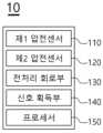
도 1을 참조하면, 본 발명의 일 실시예에 따른 차량 시트(10)는 제1 압전센서(110), 제2 압전센서(120), 전처리 회로부(130), 신호 획득부(140) 및 프로세서(150)를 포함할 수 있다. 다만, 도 1에 도시된 차량 시트(10)는 일 실시예에 따른 것이고, 그 구성요소들이 도 1에 도시된 실시예에 한정되는 것은 아니며, 필요에 따라 일부 구성요소가 부가, 변경 또는 삭제될 수 있다.Referring to FIG. 1 , a
한편, 전처리 회로부(130), 신호 획득부(140) 및 프로세서(150)는 후술하는 동작을 수행하기 위하여 ASICs(application specific integrated circuits), DSPs(digital signal processors), DSPDs(digital signal processing devices), PLDs(programmable logic devices), FPGAs(field programmable gate arrays), 제어기(controller), 마이크로 컨트롤러(micro-controllers), 마이크로 프로세서(microprocessors) 중 적어도 하나의 물리적인 요소를 포함할 수 있다.On the other hand, the
본 발명은 운전자의 생체신호 감지를 위하여 두 개의 압전센서(110, 120)를 이용할 수 있다. 압전센서는 압전효과를 가진 소자를 통해 물리력(예컨대, 진동)을 전기로 변환할 수 있는데, 본 발명은 두 개의 압전센서(110, 120)에서 발생하는 전기적 신호를 통해 생체신호를 추출할 수 있다.In the present invention, two
위와 같은 동작을 위하여 두 압전센서(110, 120) 중 어느 한 압전센서는 운전자의 신체와 맞닿는 위치에 배치될 수 있고, 다른 한 압전센서는 운전자의 신체와 맞닿지 않는 위치에 배치될 수 있다. 이하, 두 압전센서(110, 120)를 제1 및 제2 압전센서(110, 120)로 분리하여 설명하도록 한다.For the above operation, one of the two
제1 압전센서(110)는 차량 시트(10)에서 운전자의 신체와 맞닿는 위치에 배치될 수 있고, 제2 압전센서(120)는 차량 시트(10)에서 운전자의 신체와 맞닿지 않는 위치에 배치될 수 있다.The first
운전자가 차량 시트(10)에 착석하게 되면 차량 시트(10)의 일부는 운전자의 신체와 맞닿을 수 있다. 구체적으로, 운전자의 하체를 지지하는 시트쿠션(11)은 운전자의 엉덩이, 다리와 맞닿을 수 있고, 운전자의 상체를 지지하는 등받이(12)는 운전자의 허리, 등, 어깨와 맞닿을 수 있다. 이러한 차량 시트(10)와 운전자의 상호 위치 관계에 따라 두 압전센서(110, 120)가 차량 시트(10) 내 배치될 수 있다.When the driver sits on the
일 예에서, 제1 압전센서(110)는 운전자의 신체와 맞닿도록 시트쿠션(11)의 상면에 배치될 수 있다.In one example, the first
도 2a를 참조하면, 제1 압전센서(110)는 운전자의 하체와 맞닿도록 시트쿠션(11)의 상면에 배치되되, 운전자의 양 다리와 엉덩이를 아우르는 넓은 면적에 맞닿을 수 있도록 U자 형상을 가질 수 있다.Referring to FIG. 2A , the first
다른 예에서, 제1 압전센서(110)는 운전자의 신체와 맞닿도록 등받이(12)의 전면에 배치될 수 있다.In another example, the first
도 2b를 참조하면, 제1 압전센서(110)는 운전자의 상체와 맞닿도록 등받이(12)의 전면에 배치되되, 후술하는 호홉률 산출을 위하여 운전자의 흉부, 바람직하게는 횡경막과 맞닿을 수 있는 위치에서 가로 방향의 선형으로 배치될 수 있다.Referring to FIG. 2B, the first
한편, 일 예에서, 제2 압전센서(120)는 운전자의 신체와 맞닿지 않도록 시트쿠션(11)에 배치될 수 있다. 이 때, 제2 압전센서(120)가 시트쿠션(11)의 전면에 배치되는 경우 운전자의 종아리와 맞닿게 될 우려가 있으므로, 제2 압전센서(120)는 시트쿠션(11)의 측면 또는 하면에 배치될 수 있다.Meanwhile, in one example, the second
다시 도 2a를 참조하면, 제2 압전센서(120)는 운전자의 하체와 맞닿지 않도록 시트쿠션(11)의 측면에 배치되되, 시트쿠션(11)의 측면 디자인에 따라 가로 방향의 선형으로 배치될 수 있다.Referring back to FIG. 2A , the second
다른 예에서, 제2 압전센서(120)는 운전자의 신체와 맞닿지 않도록 등받이(12)에 배치될 수 있다. 이 때, 제2 압전센서(120)가 등받이(12)의 후면에 배치되는 경우 뒷좌석의 동승자의 신체에 맞닿게 될 우려가 있으므로, 제2 압전센서(120)는 등받이(12)의 측면, 바람직하게는 차량 도어에 인접한 측면에 배치될 수 있다.In another example, the second
다시 도 2b를 참조하면, 제2 압전센서(120)는 운전자의 상체와 맞닿지 않도록 등받이(12)의 측면에 배치되되, 등받이(12)의 측면 디자인에 따라 세로 방향의 선형으로 배치될 수 있다.Referring back to FIG. 2B , the second
전술한 두 압전센서(110, 120)는 차량 시트(10)의 외면에 설치되어 운전자의 신체와 직접 맞닿도록 배치될 수도 있고, 차량 시트(10)의 외피 하부에 설치되어 운전자의 신체와 간접적으로 맞닿도록 배치될 수 있다.The aforementioned two
한편, 후술하는 프로세서(150)는 제1 및 제2 압전센서(110, 120)에서 취득되는 노이즈가 동일하다는 가정 하에 생체신호 추출 동작을 수행하므로, 제1 및 제2 압전센서(110, 120)는 동일한 노이즈를 취득할 수 있도록 차량 시트(10) 내에서 동일한 부재에 배치될 수 있다.Meanwhile, since the
즉, 도 2a에 도시된 바와 같이, 제1 압전센서(110)가 시트쿠션(11)에 배치되는 경우 제2 압전센서(120) 역시 시트쿠션(11)에 배치될 수 있고, 도 2b에 도시된 바와 같이, 제1 압전센서(110)가 등받이(12)에 배치되는 경우 제2 압전센서(120) 역시 등받이(12)에 배치될 수 있다.That is, as shown in FIG. 2A, when the first
또한, 전술한 제1 및 제2 압전센서(110, 120)는 동일한 구조를 가질 수 있다. 구체적으로, 제1 및 제2 압전센서(110, 120)의 내부 구성요소들은 모두 동일할 수 있으며, 제1 및 제2 압전센서(110, 120)는 동일한 길이, 너비 및 두께를 가질 수 있다. 이에 따라, 제1 및 제2 압전센서(110, 120)에서 취득되는 노이즈는 동일하거나 매우 유사할 수 있다.Also, the aforementioned first and second
이하에서는 전술한 제1 및 제2 압전센서(110, 120)의 세부 구성을 설명하도록 한다.Hereinafter, detailed configurations of the first and second
본 발명의 제1 및 제2 압전센서(110, 120)는 운전자의 신체로부터 인가되는 압력에 따라 내부 전하 특성이 변하는 값을 감지하여 신호를 취득할 수 있다. 이 때, 제1 압전센서(110)에서 취득된 신호는 운전자의 생체신호, 예컨대, 심박, 호흡 등의 신호를 포함할 수 있다.The first and second
도 3 및 도 4를 참조하면, 압전센서(110, 120)는 외부에서 인가되는 압력에 따라 내부 전하 특성이 변하는 압전 소자(1005)를 포함할 수 있고, 압전 소자(1005)는 PVDF(polyvinylidene fluoride) 재질의 스트립형(strip-type) 소자로 구현될 수 있으나, 이에 한정되는 것은 아니다.Referring to FIGS. 3 and 4 , the
압전 소자(1005)는 스크린 프린팅(screen printing)을 사용하여 제작된 양극성 전극(bipolar electrode, 1003) 사이, 구체적으로 상부(top) 전극 및 하부(bottom) 전극 사이에 구비될 수 있다. 한편, 양극성 전극(1003)이 복수의 돌기 패턴을 가질 때, 양극성 전극(1003)은 용량성 노이즈(capacitive noise)를 고려하여 양 극의 돌기 패턴이 서로 엇갈리도록 설계될 수 있다.The
한편, 압전 센서(110, 120)를 구성하는 소자 간의 접촉 부분에는 링 터미널(ring terminal)과 아일렛(elelet)이 이용될 수 있다. 이를 통해, 압전 센서(110, 120)는 매우 얇고 유연하게 설계될 수 있으며, 이에 따라 운전자의 신체와 맞닿는 경우에도 운전자가 느끼는 이질감을 줄일 수 있다.Meanwhile, a ring terminal and an eyelet may be used as a contact portion between elements constituting the
프로세서(150)는 제1 및 제2 압전센서(110, 120)에서 취득된 신호에 기초하여 운전자의 생체신호를 추출할 수 있다.The
제1 압전센서(110)는 운전자 신체에 맞닿도록 배치되므로 제1 압전센서(110)에서 취득된 신호는 운전자 생체신호와, 외부 요인에 의하여 차량 시트(10)에 인가되는 노이즈를 포함할 수 있다. 반면에, 제2 압전센서(120)는 운전자 신체에 맞닿지 않도록 배치되므로 제2 압전센서(120)에서 취득된 신호는 차량 시트(10)에 인가되는 노이즈만을 포함할 수 있다.Since the first
프로세서(150)는 각 압전센서(110, 120)에서 취득된 신호의 차에 기초하여 생체신호만을 선택적으로 추출할 수 있다.The
도 5을 예로 들어 설명하면, 제1 압전센서(110)에서 취득된 제1 신호(S1)에는 생체신호와 노이즈가 포함될 수 있고, 제2 압전센서(120)에서 취득된 제2 신호(S2)에는 노이즈만이 포함될 수 있다. 프로세서(150)는 제1 신호(S1)에서 제2 신호(S2)를 감산함으로써 제1 신호(S1)에서 노이즈를 제거할 수 있고, 생체신호(Sd)만을 추출할 수 있다.Referring to FIG. 5 as an example, the
이하에서는 전술한 제1 및 제2 신호(S1, S2)가 처리되는 과정을 보다 구체적으로 설명하도록 한다.Hereinafter, a process of processing the above-described first and second signals S1 and S2 will be described in more detail.
도 6을 참조하면, 제1 및 제2 압전센서(110, 120)에서 취득된 신호는 전처리 회로부(130)에 의해 전처리되고, 전처리된 신호는 신호 획득부(140)를 통해 디지털 신호로 변환될 수 있다. 프로세서(150)는 디지털 신호로 변환된 신호에 기초하여 운전자의 생체신호를 추출할 수 있다.Referring to FIG. 6 , signals obtained from the first and second
도 7을 참조하면, 전처리 회로부(130)는 제1 및 제2 압전센서(110, 120)에서 출력되는 각 신호를 증폭할 수 있다. 구체적으로, 전처리 회로부(130)는 압전센서(110, 120)에서 출력되는 적은 양의 전하량을 증폭하고 증폭된 전하량에 비례하는 전압 신호를 출력할 수 있다. 이를 위해, 전처리 회로부(130)는 전하 증폭기(charge amplifier)와, 전하 증폭기에서 출력된 전압 신호를 증폭하기 위한 전압 증폭기(voltage amplifier)를 포함할 수 있다.Referring to FIG. 7 , the
신호가 증폭되면 신호 획득부(140)는 이를 디지털 신호로 변환하여 신호 데이터를 생성할 수 있다. 구체적으로, 신호 획득부(140)는 전처리 회로부(130)에서 출력되는 아날로그 전압 신호를 디지털로 변환하여 신호 데이터를 생성할 수 있고, 이를 위해 ADC(Analog Digital Converter), 레귤레이터(voltage regulator), 오실레이터(oscillator) 등을 포함할 수 있다. 이어서, 신호 획득부(140)는 디지털로 변환된 신호 데이터를 시계열적인 값으로 출력할 수 있다.When the signal is amplified, the
한편, 전술한 전처리 회로부(130)와 신호 획득부(140)는 각각 PCB(Printed Circuit Board, 131, 141) 기판과 각 PCB 기판(131, 141) 상에 구비되는 커넥터(132, 142)를 포함할 수 있고, 전처리 회로부(130)와 신호 획득부(140)는 커넥터(132, 142)를 통해 상호 연결될 수 있다. 이와 같이, 전처리 회로부(130)와 신호 획득부(140)를 분리 구성하는 경우, 향후 다채널을 통해 신호를 수집할 수 있다는 장점이 있다.On the other hand, the above-described
예컨대, 도 3에 도시된 것과 달리, 제1 및 제2 압전센서(110, 120)가 두 개의 전처리 회로부(130)에 신호를 출력하는 경우, 신호 획득부(140)는 멀티 레이어(multi-layer) PCB(141)와 각 PCB(141)에 구비된 커넥터(142)를 포함할 수 있고, 두 개의 전처리 회로부(130)는 신호 획득부(140) 내 각 PCB(141)에 구비된 커넥터(142)에 접속될 수 있다.For example, unlike that shown in FIG. 3 , when the first and second
또한, 차량 시트(10)에 추가적인 압전센서가 더 포함되는 경우, 전처리 회로부(130)는 멀티 레이어 PCB(131)를 통해, 제1 및 제2 압전센서(110, 120)뿐만 아니라 추가 압전센서로부터 신호를 더 수신할 수 있고, 이를 커넥터(132)를 통해 신호 획득부(140)에 제공할 수 있다.In addition, when an additional piezoelectric sensor is further included in the
프로세서(150)는 신호 획득부(140)에서 출력되는 각 신호 데이터의 차이에 기초하여 생체신호를 추출할 수 있다. 구체적으로, 프로세서(150)는 제1 압전센서(110)에서 취득되어 변환된 신호 데이터에서, 제2 압전센서(120)에서 취득되어 변환된 신호 데이터를 감산한 신호 차이를 생체신호로 추출할 수 있다.The
전술한 바와 같이, 본 발명은 운전자의 신체와 맞닿는 압전센서에서 취득된 신호와 운전자의 신체와 맞닿지 않는 압전센서에서 취득된 신호의 차이에 기초하여 운전자의 생체신호를 추출함으로써, 차량에서 발생하는 노이즈를 효과적으로 제거하여 생체신호만을 선택적으로 분리할 수 있는 효과가 있다.As described above, the present invention extracts a driver's biosignal based on a difference between a signal acquired from a piezoelectric sensor in contact with the driver's body and a signal obtained from a piezoelectric sensor not in contact with the driver's body. There is an effect of selectively separating only biosignals by effectively removing noise.
이하에서는, 도 8 내지 도 10을 참조하여 프로세서(150)가 생체신호를 통해 운전자의 호흡률을 산출하는 방법을 예시적으로 설명하도록 한다.Hereinafter, a method for the
도 8을 참조하면, 프로세서(150)는 생체신호(Sd)에 대해 필터링 전처리를 수행할 수 있다.Referring to FIG. 8 , the
보다 구체적으로, 프로세서(150)는 생체신호(Sd)에 포함되는 전력선 간섭(예컨대, 60Hz의 노이즈)을 제거하기 위하여, 생체신호(Sd)를 노치 필터(notch filter)에 적용할 수 있다(S11). 예컨대, 프로세서(150)는 생체신호를 IIR(Infinite Impulse Response) 노치 필터에 적용시킬 수 있고, 이에 따라, 생체신호(Sd)에서 전력선 간섭이 제거될 수 있다.More specifically, the
이어서, 프로세서(150)는 움직임 성분(motion component)을 선택적으로 취득하기 위하여, 노치 필터가 적용된 생체신호를 대역통과필터(Band Pass Filter; BPF)에 적용할 수 있다(S12). 구체적으로 프로세서(150)는 생체신호를 0.4 내지 1[Hz]의 통과 대역을 갖는 IIR 대역통과필터에 적용할 수 있다. 이에 따라, 생체신호 내 움직임 성분만이 분리 취득될 수 있다.Subsequently, the
이어서, 프로세서(150)는 앞서 전처리된 생체신호의 표준편차를 이용하여 각성 구간(awake section)을 결정할 수 있다.Subsequently, the
다시 도 8을 참조하면, 프로세서(150)는 전처리된 생체신호의 표준편차를 산출할 수 있다(S13). 구체적으로, 프로세서(150)는 오버랩된 시간 윈도우(예컨대, 7초)에 대하여, 생체신호의 표준편차(SDsignal)를 반복적으로 산출할 수 있다.Referring back to FIG. 8 , the
이어서, 프로세서(150)는 산출된 표준편차(SDsignal)의 히스토그램(histogram)을 생성할 수 있고(S14), 히스토그램의 최대값보다 작은 빈(bin)에 가우스 함수를 적용하여 가우스 함수값을 산출할 수 있다(S15).Subsequently, the
이어서, 프로세서(150)는 가우스 함수값의 표준편차를 산출할 수 있고, 이에 기초하여 각성 구간을 결정하기 위한 임계값을 설정할 수 있다. 예를 들어, 프로세서(150)는 가우스 함수값의 표준편차가

이어서, 프로세서(150)는 생체신호의 표준편차와 임계값의 비교 결과에 따라 전기신호의 각성 구간을 결정할 수 있다(S16).Subsequently, the
도 9를 참조하여 구체적으로 설명하면, 프로세서(150)는 생체신호의 표준편차에 대한 히스토그램에서 임계값보다 큰 우측 영역을 각성 구간으로 결정할 수 있고, 임계값보다 작은 좌측 영역을 수면 구간(sleep section)으로 결정할 수 있다.In detail with reference to FIG. 9 , the
각성 구간의 결정이 완료되면, 프로세서(150)는 생체신호에서 각성 구간을 제거하고, 각성 구간이 제거된 생체신호에 대하여 필터링 후처리를 수행할 수 있다.When the determination of the arousal interval is completed, the
다시 도 8을 참조하면, 프로세서(150)는 동잡음(motion artifact)을 포함하는 각성 구간을 생체신호로부터 제거할 수 있고(S17), 생체신호에서 제거된 구간을 이웃 데이터를 이용하여 보간(interpolation)할 수 있다.Referring back to FIG. 8 , the
이어서, 프로세서(150)는 보간된 생체신호에 대역통과필터를 적용할 수 있다(S18). 구체적으로, 프로세서(150)는 호흡 성분을 추출하기 위하여 보간된 생체신호를 0.1 내지 0.5[Hz]의 통과 대역을 갖는 IIR 대역통과필터에 적용할 수 있다.Subsequently, the
이어서, 프로세서(150)는 대역통과필터에 의해 필터링된 생체신호의 평활화(smoothing)를 위해, 해당 생체신호를 이동평균필터(Moving Average Filter; MAF)에 적용할 수 있다(S19). 예컨대, 프로세서(150)는 2초의 시간 윈도우에 대하여, 생체신호에 이동평균필터를 적용할 수 있다.Subsequently, the
즉, 사용자 움직임에 의해 발생한 신호는 단계(S17) 내지 단계(S19)의 후처리 과정을 통해 동잡음이 제거되고 순수한 호흡 성분만이 추출될 수 있다.That is, in the signal generated by the user's movement, motion noise is removed through the post-processing of steps S17 to S19, and only pure respiratory components can be extracted.
이어서, 프로세서(150)는 후처리된 생체신호에 푸리에 변환(Fourier transform)을 적용하여 호흡률을 산출할 수 있다.Subsequently, the
프로세서(150)는 후처리된 생체신호를 푸리에 변환하여 생체신호에 대한 주파수 성분을 산출할 수 있다(S20). 구체적으로, 프로세서(150)는 시간에 따른 크기로 표현되는 생체신호를 푸리에 변환하여 주파수 성분에 따른 크기로 표현되는 신호를 생성할 수 있다. 즉, 도 10에 도시된 바와 같이 시간(slow-time index)에 따른 크기(amplitude)로 표현되는 생체신호는 푸리에 변환되어 주파수 성분에 따른 크기로 표현될 수 있다.The
한편, 푸리에 변환을 수행함에 있어서, 프로세서(150)는 생체신호에 고속 푸리에 변환(Fast Fourier Transform; FFT)을 적용하여 생체신호를 이산 푸리에 변환(Discrete Fourier Transform; DFT)할 수 있다. 다시 말해, 프로세서(150)는 이산화된 시간에 대한 생체신호를 이산화된 주파수에 대한 생체신호로 변환할 수 있고, 변환 속도를 증가시키기 위하여 고속 푸리에 변환(FFT)을 이용할 수 있다.Meanwhile, in performing the Fourier transform, the
전술한 푸리에 변환이 완료되면, 프로세서(150)는 푸리에 변환된 생체신호의 주파수 성분 중 최대 크기를 갖는 주파수에 기초하여 호흡률을 산출할 수 있다(S21).When the above-described Fourier transform is completed, the
예컨대, 푸리에 변환된 생체신호가 도 10에 도시된 것과 같은 경우, 프로세서(150)는 생체신호에 포함된 주파수 성분들 중에서 최대 크기를 갖는 주파수를 주파수를 0.45[Hz]로 식별할 수 있다. 프로세서(150)는 해당 주파수에 기초하여 호흡률을 분당 27회로 산출할 수 있다.For example, when the Fourier-transformed biosignal is as shown in FIG. 10 , the
이상과 같이 본 발명에 대해서 예시한 도면을 참조로 하여 설명하였으나, 본 명세서에 개시된 실시 예와 도면에 의해 본 발명이 한정되는 것은 아니며, 본 발명의 기술사상의 범위 내에서 통상의 기술자에 의해 다양한 변형이 이루어질 수 있음은 자명하다. 아울러 앞서 본 발명의 실시 예를 설명하면서 본 발명의 구성에 따른 작용 효과를 명시적으로 기재하여 설명하지 않았을 지라도, 해당 구성에 의해 예측 가능한 효과 또한 인정되어야 함은 당연하다.As described above, the present invention has been described with reference to the drawings illustrated, but the present invention is not limited by the embodiments and drawings disclosed in this specification, and various modifications are made by those skilled in the art within the scope of the technical idea of the present invention. It is obvious that variations can be made. In addition, although the operational effects according to the configuration of the present invention have not been explicitly described and described while describing the embodiments of the present invention, it is natural that the effects predictable by the corresponding configuration should also be recognized.
Claims (9)
Translated fromKorean상기 운전자의 신체와 맞닿는 위치에 배치되는 제1 압전센서;
상기 운전자의 신체와 맞닿지 않는 위치에 배치되는 제2 압전센서; 및
상기 제1 및 제2 압전센서에서 취득된 신호에 기초하여 상기 생체신호를 추출하는 프로세서를 포함하는
생체신호 감지를 위한 차량 시트.
In a vehicle seat for detecting a biosignal of a seated driver,
a first piezoelectric sensor disposed at a position in contact with the driver's body;
a second piezoelectric sensor disposed at a position not in contact with the driver's body; and
And a processor for extracting the biosignal based on the signals acquired from the first and second piezoelectric sensors.
Vehicle seat for bio-signal detection.
상기 제1 압전센서는 상기 운전자의 신체와 맞닿도록 시트쿠션의 상면에 배치되는 생체신호 감지를 위한 차량 시트.
According to claim 1,
The first piezoelectric sensor is disposed on an upper surface of a seat cushion to come into contact with the driver's body.
상기 제1 압전센서는 상기 운전자의 신체와 맞닿도록 등받이의 전면에 배치되는 생체신호 감지를 위한 차량 시트.
According to claim 1,
The first piezoelectric sensor is disposed on the front surface of the backrest so as to come into contact with the driver's body.
상기 제2 압전센서는 상기 운전자의 신체와 맞닿지 않도록 시트쿠션의 측면에 배치되는 생체신호 감지를 위한 차량 시트.
According to claim 1,
The second piezoelectric sensor is disposed on a side surface of a seat cushion so as not to come into contact with the driver's body.
상기 제2 압전센서는 상기 운전자의 신체와 맞닿지 않도록 등받이의 측면에 배치되는 생체신호 감지를 위한 차량 시트.
According to claim 1,
The second piezoelectric sensor is disposed on a side surface of the backrest so as not to come into contact with the driver's body.
상기 제1 및 제2 압전센서는 동일한 구조를 갖는 생체신호 감지를 위한 차량 시트.
According to claim 1,
The first and second piezoelectric sensors have the same structure and a vehicle seat for sensing biosignals.
상기 프로세서는 상기 제1 압전센서에서 취득된 신호에서 상기 제2 압전센서에서 취득된 신호를 감산한 신호 차이를 생체신호로 추출하는 생체신호 감지를 위한 차량 시트.
According to claim 1,
wherein the processor extracts, as a biosignal, a signal difference obtained by subtracting the signal obtained from the second piezoelectric sensor from the signal obtained from the first piezoelectric sensor.
상기 제1 및 제2 압전센서에서 출력되는 각 신호를 증폭하는 전처리 회로부와,
상기 증폭된 각 신호를 디지털 신호로 변환하여 신호 데이터를 각각 생성하고 상기 신호 데이터를 시계열적인 값으로 출력하는 신호 획득부를 더 포함하고,
상기 프로세서는 각 신호 데이터의 차이에 기초하여 생체신호를 추출하는
생체신호 감지를 위한 차량 시트.
According to claim 1,
a pre-processing circuit unit for amplifying each signal output from the first and second piezoelectric sensors;
Further comprising a signal acquisition unit that converts each of the amplified signals into digital signals to generate signal data and outputs the signal data as time-series values;
The processor extracts a biosignal based on the difference between each signal data
Vehicle seat for bio-signal detection.
상기 프로세서는 상기 생체신호에 대해 필터링 전처리를 수행하고, 상기 전처리된 생체신호의 표준편차를 이용하여 각성 구간을 결정하고, 상기 각성 구간이 제거된 생체신호에 대하여 필터링 후처리를 수행하고, 상기 후처리된 생체신호에 푸리에 변환을 적용하여 호흡률을 산출하는
생체신호 감지를 위한 차량 시트.According to claim 1,
The processor performs filtering pre-processing on the bio-signal, determines an arousal section using the standard deviation of the pre-processed bio-signal, performs filtering post-processing on the bio-signal from which the arousal section is removed, and Respiratory rate is calculated by applying Fourier transform to the processed biosignal.
Vehicle seat for bio-signal detection.
Priority Applications (1)
| Application Number | Priority Date | Filing Date | Title |
|---|---|---|---|
| KR1020210161402AKR102643158B1 (en) | 2021-11-22 | 2021-11-22 | Vehicle seat for sensing bio-signal |
Applications Claiming Priority (1)
| Application Number | Priority Date | Filing Date | Title |
|---|---|---|---|
| KR1020210161402AKR102643158B1 (en) | 2021-11-22 | 2021-11-22 | Vehicle seat for sensing bio-signal |
Publications (2)
| Publication Number | Publication Date |
|---|---|
| KR20230075122Atrue KR20230075122A (en) | 2023-05-31 |
| KR102643158B1 KR102643158B1 (en) | 2024-03-04 |
Family
ID=86543070
Family Applications (1)
| Application Number | Title | Priority Date | Filing Date |
|---|---|---|---|
| KR1020210161402AActiveKR102643158B1 (en) | 2021-11-22 | 2021-11-22 | Vehicle seat for sensing bio-signal |
Country Status (1)
| Country | Link |
|---|---|
| KR (1) | KR102643158B1 (en) |
Citations (8)
| Publication number | Priority date | Publication date | Assignee | Title |
|---|---|---|---|---|
| KR20080093456A (en)* | 2006-02-08 | 2008-10-21 | 도요다 지도샤 가부시끼가이샤 | Automotive thermal stimulation device |
| KR101679976B1 (en)* | 2015-05-29 | 2016-11-25 | 현대자동차주식회사 | Apparatus for measuring electrocardiogram in vehicle |
| KR101731190B1 (en) | 2015-11-30 | 2017-04-27 | 계명대학교 산학협력단 | Apparatus for sensing of driver's condition using electrocardiogram and method thereof |
| US20180333093A1 (en)* | 2017-05-19 | 2018-11-22 | Lear Corporation | Methods and Systems for Detecting from Biometrics that Person Sitting in Seat of Vehicle Requires Medical Attention and for Providing Medical Attention to the Person |
| KR20190055313A (en)* | 2017-11-15 | 2019-05-23 | 주식회사 서연전자 | Driver sensing device and method thereof |
| JP2020058743A (en)* | 2018-10-12 | 2020-04-16 | パナソニックIpマネジメント株式会社 | Surveillance equipment, surveillance systems, seats, vehicles, and programs |
| KR20200098989A (en)* | 2019-02-13 | 2020-08-21 | 전남대학교산학협력단 | A method and apparatus for detecting awakening and respiration rate based on force-sensor |
| KR20210080558A (en)* | 2019-11-22 | 2021-06-30 | 마터 이탤리 에스알엘 | Smart cover for vehicle seat and vehicle seat comprising smart cover |
- 2021
- 2021-11-22KRKR1020210161402Apatent/KR102643158B1/enactiveActive
Patent Citations (8)
| Publication number | Priority date | Publication date | Assignee | Title |
|---|---|---|---|---|
| KR20080093456A (en)* | 2006-02-08 | 2008-10-21 | 도요다 지도샤 가부시끼가이샤 | Automotive thermal stimulation device |
| KR101679976B1 (en)* | 2015-05-29 | 2016-11-25 | 현대자동차주식회사 | Apparatus for measuring electrocardiogram in vehicle |
| KR101731190B1 (en) | 2015-11-30 | 2017-04-27 | 계명대학교 산학협력단 | Apparatus for sensing of driver's condition using electrocardiogram and method thereof |
| US20180333093A1 (en)* | 2017-05-19 | 2018-11-22 | Lear Corporation | Methods and Systems for Detecting from Biometrics that Person Sitting in Seat of Vehicle Requires Medical Attention and for Providing Medical Attention to the Person |
| KR20190055313A (en)* | 2017-11-15 | 2019-05-23 | 주식회사 서연전자 | Driver sensing device and method thereof |
| JP2020058743A (en)* | 2018-10-12 | 2020-04-16 | パナソニックIpマネジメント株式会社 | Surveillance equipment, surveillance systems, seats, vehicles, and programs |
| KR20200098989A (en)* | 2019-02-13 | 2020-08-21 | 전남대학교산학협력단 | A method and apparatus for detecting awakening and respiration rate based on force-sensor |
| KR20210080558A (en)* | 2019-11-22 | 2021-06-30 | 마터 이탤리 에스알엘 | Smart cover for vehicle seat and vehicle seat comprising smart cover |
Also Published As
| Publication number | Publication date |
|---|---|
| KR102643158B1 (en) | 2024-03-04 |
Similar Documents
| Publication | Publication Date | Title |
|---|---|---|
| US8262582B2 (en) | Extraction of heart inter beat interval from multichannel measurements | |
| EP2429390B1 (en) | System and methods using flexible capacitive electrodes for measuring biosignals | |
| US10231628B2 (en) | Method for measuring movements of a person wearing a portable detector | |
| CN108888271B (en) | A physiological parameter measurement system and an intelligent seat equipped with the measurement system | |
| JP3913748B2 (en) | Snoring detection method and detection apparatus | |
| JP7177443B2 (en) | Biological vibration signal detector | |
| JP4962735B2 (en) | Biological information acquisition device | |
| WO2016198963A2 (en) | Electrodes for abdominal fetal electrocardiogram detection | |
| EP2501277A1 (en) | Apparatus and methods for monitoring heart rate and respiration | |
| CN110115574A (en) | The method and apparatus of rhythm of the heart | |
| US20140378859A1 (en) | Method of Multichannel Galvanic Skin Response Detection for Improving Measurement Accuracy and Noise/Artifact Rejection | |
| Vetter et al. | Integration of an electromagnetic coupled sensor into a driver seat for vital sign monitoring: Initial insight | |
| US20110196243A1 (en) | Non-contact detection of physiological data using stochastic resonance | |
| JP7217470B2 (en) | Heartbeat signal detection device and heartbeat signal detection program | |
| CN115153580B (en) | A skin impedance measurement method and system for fetal electrocardiogram monitoring | |
| JP4998896B2 (en) | Cardiopulmonary function measuring device | |
| KR102643158B1 (en) | Vehicle seat for sensing bio-signal | |
| CN113017559A (en) | Vital sign extraction algorithm and system based on piezoelectric film sensor | |
| JP6386402B2 (en) | Sensor device for detecting displacement of human body surface accompanying breathing | |
| JP4345489B2 (en) | Respiration monitor device | |
| JP2002102187A (en) | Biological detector | |
| CN106419884A (en) | Heart rate calculating method and system based on wavelet analysis | |
| JP6731785B2 (en) | Reliability determination device and reliability determination method | |
| JPH1119056A (en) | Method and device for measurement of heart rate | |
| Heuer et al. | Signal quality assessment for capacitive ECG monitoring systems using body-sensor-impedance |
Legal Events
| Date | Code | Title | Description |
|---|---|---|---|
| PA0109 | Patent application | Patent event code:PA01091R01D Comment text:Patent Application Patent event date:20211122 | |
| PA0201 | Request for examination | ||
| PG1501 | Laying open of application | ||
| E902 | Notification of reason for refusal | ||
| PE0902 | Notice of grounds for rejection | Comment text:Notification of reason for refusal Patent event date:20230717 Patent event code:PE09021S01D | |
| E701 | Decision to grant or registration of patent right | ||
| PE0701 | Decision of registration | Patent event code:PE07011S01D Comment text:Decision to Grant Registration Patent event date:20240118 | |
| GRNT | Written decision to grant | ||
| PR0701 | Registration of establishment | Comment text:Registration of Establishment Patent event date:20240227 Patent event code:PR07011E01D | |
| PR1002 | Payment of registration fee | Payment date:20240227 End annual number:3 Start annual number:1 | |
| PG1601 | Publication of registration |