KR20230064444A - Electronic apparatus - Google Patents
Electronic apparatusDownload PDFInfo
- Publication number
- KR20230064444A KR20230064444AKR1020210150034AKR20210150034AKR20230064444AKR 20230064444 AKR20230064444 AKR 20230064444AKR 1020210150034 AKR1020210150034 AKR 1020210150034AKR 20210150034 AKR20210150034 AKR 20210150034AKR 20230064444 AKR20230064444 AKR 20230064444A
- Authority
- KR
- South Korea
- Prior art keywords
- housing
- electronic device
- power
- main body
- power supply
- Prior art date
- Legal status (The legal status is an assumption and is not a legal conclusion. Google has not performed a legal analysis and makes no representation as to the accuracy of the status listed.)
- Pending
Links
Images


Classifications
- G—PHYSICS
- G06—COMPUTING OR CALCULATING; COUNTING
- G06F—ELECTRIC DIGITAL DATA PROCESSING
- G06F1/00—Details not covered by groups G06F3/00 - G06F13/00 and G06F21/00
- G06F1/16—Constructional details or arrangements
- G06F1/1613—Constructional details or arrangements for portable computers
- G06F1/1633—Constructional details or arrangements of portable computers not specific to the type of enclosures covered by groups G06F1/1615 - G06F1/1626
- G06F1/1675—Miscellaneous details related to the relative movement between the different enclosures or enclosure parts
- G06F1/1683—Miscellaneous details related to the relative movement between the different enclosures or enclosure parts for the transmission of signal or power between the different housings, e.g. details of wired or wireless communication, passage of cabling
- G—PHYSICS
- G06—COMPUTING OR CALCULATING; COUNTING
- G06F—ELECTRIC DIGITAL DATA PROCESSING
- G06F1/00—Details not covered by groups G06F3/00 - G06F13/00 and G06F21/00
- G06F1/16—Constructional details or arrangements
- G—PHYSICS
- G06—COMPUTING OR CALCULATING; COUNTING
- G06F—ELECTRIC DIGITAL DATA PROCESSING
- G06F1/00—Details not covered by groups G06F3/00 - G06F13/00 and G06F21/00
- G06F1/16—Constructional details or arrangements
- G06F1/1613—Constructional details or arrangements for portable computers
- G06F1/1633—Constructional details or arrangements of portable computers not specific to the type of enclosures covered by groups G06F1/1615 - G06F1/1626
- G06F1/1637—Details related to the display arrangement, including those related to the mounting of the display in the housing
- G06F1/1652—Details related to the display arrangement, including those related to the mounting of the display in the housing the display being flexible, e.g. mimicking a sheet of paper, or rollable
- G—PHYSICS
- G06—COMPUTING OR CALCULATING; COUNTING
- G06F—ELECTRIC DIGITAL DATA PROCESSING
- G06F1/00—Details not covered by groups G06F3/00 - G06F13/00 and G06F21/00
- G06F1/16—Constructional details or arrangements
- G06F1/1613—Constructional details or arrangements for portable computers
- G06F1/1633—Constructional details or arrangements of portable computers not specific to the type of enclosures covered by groups G06F1/1615 - G06F1/1626
- G06F1/1675—Miscellaneous details related to the relative movement between the different enclosures or enclosure parts
- G06F1/1681—Details related solely to hinges
- G—PHYSICS
- G06—COMPUTING OR CALCULATING; COUNTING
- G06F—ELECTRIC DIGITAL DATA PROCESSING
- G06F1/00—Details not covered by groups G06F3/00 - G06F13/00 and G06F21/00
- G06F1/16—Constructional details or arrangements
- G06F1/18—Packaging or power distribution
- G—PHYSICS
- G06—COMPUTING OR CALCULATING; COUNTING
- G06F—ELECTRIC DIGITAL DATA PROCESSING
- G06F1/00—Details not covered by groups G06F3/00 - G06F13/00 and G06F21/00
- G06F1/16—Constructional details or arrangements
- G06F1/18—Packaging or power distribution
- G06F1/183—Internal mounting support structures, e.g. for printed circuit boards, internal connecting means
- G06F1/188—Mounting of power supply units
- G—PHYSICS
- G06—COMPUTING OR CALCULATING; COUNTING
- G06F—ELECTRIC DIGITAL DATA PROCESSING
- G06F1/00—Details not covered by groups G06F3/00 - G06F13/00 and G06F21/00
- G06F1/26—Power supply means, e.g. regulation thereof
- G—PHYSICS
- G06—COMPUTING OR CALCULATING; COUNTING
- G06F—ELECTRIC DIGITAL DATA PROCESSING
- G06F1/00—Details not covered by groups G06F3/00 - G06F13/00 and G06F21/00
- G06F1/26—Power supply means, e.g. regulation thereof
- G06F1/263—Arrangements for using multiple switchable power supplies, e.g. battery and AC
Landscapes
- Engineering & Computer Science (AREA)
- Theoretical Computer Science (AREA)
- Physics & Mathematics (AREA)
- General Engineering & Computer Science (AREA)
- General Physics & Mathematics (AREA)
- Computer Hardware Design (AREA)
- Human Computer Interaction (AREA)
- Power Engineering (AREA)
- Computer Networks & Wireless Communication (AREA)
- Charge And Discharge Circuits For Batteries Or The Like (AREA)
Abstract
Translated fromKoreanDescription
Translated fromKorean본 개시는 전자 장치에 관한 것으로, 보다 구체적으로는 폴더블한 2개의 하우징을 갖는 전원 공급 장치를 포함하는 전자 장치에 관한 것이다.The present disclosure relates to an electronic device, and more particularly, to an electronic device including a power supply device having two foldable housings.
종래의 전자 장치는, 본체 내부에 전원 공급 장치를 내장하고 있다. 최근, 전자 장치가 고성능화, 대형화됨에 따라 소모 전력이 증가하고, 그에 따라 전원 공급 장치의 부피가 증가하여, 전원 공급 장치가 내장된 전자 장치의 두께가 증가하게 되었다.Conventional electronic devices have a built-in power supply device inside the main body. Recently, as electronic devices have increased in performance and size, power consumption has increased, and accordingly, the volume of power supply devices has increased, resulting in an increase in the thickness of the electronic device in which the power supply device is embedded.
즉, 전원 공급 장치의 구조가 전자 장치의 두께를 결정하게 되어, 전자 장치의 컴팩트한 두께와 미려한 디자인을 구현하는데 제약이 되고 있는 문제점이 있었다.That is, since the structure of the power supply device determines the thickness of the electronic device, there is a problem in that it becomes a limitation in implementing a compact thickness and beautiful design of the electronic device.
본 개시는 상술한 필요성에 따른 것으로, 본 개시의 목적은 폴더블한 2개의 하우징을 갖는 전원 공급 장치를 포함하는 전자 장치를 제공하는 데 있다.The present disclosure is in accordance with the above-described needs, and an object of the present disclosure is to provide an electronic device including a power supply device having two foldable housings.
본 개시의 일 실시예에 따른 전자 장치는, 본체 및 상기 본체와 전기적으로 연결되는 전원 공급 장치를 포함하고, 상기 전원 공급 장치는, AC 전원을 입력받는 제1 회로를 수용하는 제1 하우징, 상기 본체로 DC 전원을 공급하는 제2 회로를 수용하는 제2 하우징, 상기 제1 하우징과 상기 제2 하우징을 회전 가능하게 연결하는 힌지 모듈 및 상기 제1 회로와 상기 제2 회로를 전기적으로 연결하는 플렉서블 부재를 포함할 수 있다.An electronic device according to an embodiment of the present disclosure includes a main body and a power supply device electrically connected to the main body, wherein the power supply device includes: a first housing accommodating a first circuit receiving AC power; A second housing accommodating a second circuit supplying DC power to the main body, a hinge module rotatably connecting the first housing and the second housing, and a flexible electrically connecting the first circuit and the second circuit may include absences.
상기 플렉서블 부재는, 금속 와이어 또는 연성 회로 기판일 수 있다.The flexible member may be a metal wire or a flexible circuit board.
상기 힌지 모듈은, 상기 제1 및 제2 하우징의 사이에 배치되는 힌지 하우징 및 상기 힌지 하우징에 수용되는 힌지 구조물을 포함할 수 있다.The hinge module may include a hinge housing disposed between the first and second housings and a hinge structure accommodated in the hinge housing.
상기 플렉서블 부재는 힌지 하우징를 경유할 수 있다.The flexible member may pass through the hinge housing.
상기 힌지 구조물은, 상기 제1 하우징과 상기 힌지 하우징을 회전 가능하게 연결하는 제1 샤프트 및 상기 제2 하우징과 상기 힌지 하우징을 회전 가능하게 연결하고, 상기 제1 샤프트와 나란하게 배치되는 제2 샤프트를 포함할 수 있다.The hinge structure includes a first shaft rotatably connecting the first housing and the hinge housing and a second shaft rotatably connecting the second housing and the hinge housing and disposed parallel to the first shaft. can include
상기 전원 공급 장치는, 일면에 상기 제1 회로가 배치되는 제1 기판 및 일면에 상기 제2 회로가 배치되는 제2 기판을 더 포함하고, 상기 제1 및 제2 하우징이 완전히 접힌 상태에서, 상기 제1 기판의 일면은 상기 제2 기판의 타면과 마주하도록 배치될 수 있다.The power supply device further includes a first substrate on one surface of which the first circuit is disposed and a second substrate on one surface of which the second circuit is disposed, and in a state in which the first and second housings are completely folded, the One surface of the first substrate may be disposed to face the other surface of the second substrate.
상기 제1 및 제2 하우징이 완전히 접힌 상태에서, 상기 제1 하우징의 일면은 상기 제2 하우징의 일면과 마주하도록 배치되고, 상기 전원 공급 장치는, 상기 제1 하우징에 일면에 배치되는 제1 자성 부재 및 상기 제2 하우징의 일면 중 상기 제1 자성 부재와 대응되는 위치에 배치되고, 상기 제1 자성 부재와 반대되는 극성을 갖는 제2 자성 부재를 더 포함할 수 있다.In a completely folded state of the first and second housings, one surface of the first housing is disposed to face one surface of the second housing, and the power supply unit includes a first magnet disposed on one surface of the first housing. The device may further include a second magnetic member disposed at a position corresponding to the first magnetic member on one surface of the member and the second housing and having a polarity opposite to that of the first magnetic member.
상기 제1 및 제2 하우징 중 적어도 하나는, 영상 신호를 입력 받는 미디어 포트를 포함하고, 상기 제1 및 제2 회로 중 적어도 하나는, 상기 영상 신호를 디코딩할 수 있다.At least one of the first and second housings may include a media port for receiving a video signal, and at least one of the first and second circuits may decode the video signal.
상기 제2 하우징은, 일면에 배치되는 복수의 DC 전원 출력 포트를 포함할 수 있다.The second housing may include a plurality of DC power output ports disposed on one surface.
상기 전원 공급 장치는, 상기 제2 하우징의 일면에 슬라이딩 가능하게 배치되어, 상기 복수의 DC 전원 출력 포트 중 하나만 선택적으로 노출시키는 도어 부재를 더 포함할 수 있다.The power supply device may further include a door member slidably disposed on one surface of the second housing and selectively exposing only one of the plurality of DC power output ports.
상기 제1 및 제2 회로 중 적어도 하나는, AC 전원을 DC 전원으로 변환할 수 있다.At least one of the first and second circuits may convert AC power to DC power.
상기 본체는, 배면에 상기 제2 하우징의 DC 전원 출력 포트와 전기적으로 연결되는 DC 전원 입력 포트를 포함하고, 상기 DC 전원 출력 포트 및 상기 DC 전원 입력 포트는, 서로 맞물리는 형상을 가질 수 있다.The main body may include a DC power input port electrically connected to a DC power output port of the second housing on a rear surface thereof, and the DC power output port and the DC power input port may have shapes interlocking with each other.
상기 전자 장치는, 상기 제2 하우징의 DC 전원 출력 포트와 상기 본체의 DC 전원 입력 포트를 전기적으로 연결하는 와이어 부재를 더 포함할 수 있다.The electronic device may further include a wire member electrically connecting a DC power output port of the second housing and a DC power input port of the main body.
상기 전자 장치는, 상기 본체를 지지하는 스탠드를 더 포함하고, 상기 제1 하우징은 상기 스탠드의 배면에 장착되고, 상기 제2 하우징은 상기 본체의 배면에 장착될 수 있다.The electronic device may further include a stand supporting the main body, the first housing may be mounted on a rear surface of the stand, and the second housing may be mounted on a rear surface of the main body.
상기 스탠드는, 배면에 돌출 형성된 제1 고정 돌기를 포함하고, 상기 제1 하우징은, 상기 제1 고정 돌기와 맞물리는 형상을 갖는 고정 홈을 포함할 수 있다.The stand may include a first fixing protrusion protruding from a rear surface thereof, and the first housing may include a fixing groove having a shape engaged with the first fixing protrusion.
상기 제1 하우징의 너비는, 상기 스탠드의 너비와 같거나 상기 스탠드의 너비보다 작을 수 있다.A width of the first housing may be equal to or smaller than that of the stand.
상기 스탠드는, 바닥에 수평하게 배치되는 제1 지지 부재 및 상기 제1 지지 부재와 상기 본체의 배면을 연결하는 제2 지지 부재를 포함하고, 상기 본체와 상기 제2 지지 부재의 사이각은, 상기 제1 하우징과 상기 제2 하우징의 사이각과 동일할 수 있다.The stand includes a first support member disposed horizontally on the floor and a second support member connecting the first support member and the rear surface of the main body, and the angle between the main body and the second support member is It may be equal to the angle between the first housing and the second housing.
상기 전자 장치는, 상기 본체를 벽에 고정시키는 월 마운트를 더 포함하고, 상기 제1 및 제2 하우징은 상기 본체의 배면에 장착될 수 있다.The electronic device may further include a wall mount fixing the main body to a wall, and the first and second housings may be mounted on a rear surface of the main body.
상기 본체는 배면에 돌출 형성된 제2 고정 돌기를 포함하고, 상기 제1 하우징은, 상기 제2 고정 돌기와 맞물리는 형상을 갖는 고정 홈을 포함할 수 있다.The main body may include a second fixing protrusion protruding from a rear surface thereof, and the first housing may include a fixing groove having a shape engaged with the second fixing protrusion.
상기 전자 장치는, 상기 전원 공급 장치를 둘러싸는 커버 부재를 더 포함할 수 있다.The electronic device may further include a cover member surrounding the power supply device.
도 1은 본 개시의 일 실시예에 따른 전원 공급 장치의 정면도이다.
도 2는 전원 공급 장치의 펼쳐진 상태, 접힌 상태, 완전히 접힌 상태를 나타내는 측면도이다.
도 3 및 도 4는 전원 공급 장치가 AC 전원을 DC 전원으로 변환하는 과정을 나타내는 흐름도이다.
도 5는 전원 공급 장치의 완전히 접힌 상태를 나타내는 측면도이다.
도 6 및 도 7은 스탠드형 전자 장치에 전원 공급 장치가 장착되는 구조를 설명하는 도면이다.
도 8 및 도 9은 벽걸이형 전자 장치에 전원 공급 장치가 장착되는 구조를 설명하는 도면이다.
도 10 내지 도 12는 복수의 DC 전원 출력 포트가 형성된 전원 공급 장치가 전자 장치에 장착되는 구조를 설명하는 도면이다.
도 13은 전원 공급 장치가 와이어 부재를 통하여 전자 장치와 연결된 구조를 설명하는 도면이다.
도 14는 전원 공급 장치를 둘러싸는 커버 부재의 구조를 설명하는 도면이다.1 is a front view of a power supply device according to an embodiment of the present disclosure.
2 is a side view showing a power supply device in an unfolded state, a folded state, and a fully folded state.
3 and 4 are flowcharts illustrating a process in which the power supply converts AC power to DC power.
5 is a side view showing the fully folded state of the power supply.
6 and 7 are views illustrating a structure in which a power supply device is mounted in a stand-type electronic device.
8 and 9 are views illustrating a structure in which a power supply device is mounted in a wall-mounted electronic device.
10 to 12 are diagrams illustrating a structure in which a power supply device having a plurality of DC power output ports is mounted on an electronic device.
13 is a diagram explaining a structure in which a power supply device is connected to an electronic device through a wire member.
14 is a diagram explaining the structure of a cover member enclosing a power supply device.
이하에서 설명되는 실시 예는 본 개시의 이해를 돕기 위하여 예시적으로 나타낸 것이며, 본 개시는 여기서 설명되는 실시 예들과 다르게, 다양하게 변형되어 실시될 수 있음이 이해되어야 할 것이다. 다만, 이하에서 본 개시를 설명함에 있어서, 관련된 공지 기능 혹은 구성요소에 대한 구체적인 설명이 본 개시의 요지를 불필요하게 흐릴 수 있다고 판단되는 경우 그 상세한 설명 및 구체적인 도시를 생략한다. 또한, 첨부된 도면은 개시의 이해를 돕기 위하여 실제 축척대로 도시된 것이 아니라 일부 구성요소의 치수가 과장되게 도시될 수 있다.Embodiments described below are shown by way of example to aid understanding of the present disclosure, and it should be understood that the present disclosure may be implemented with various modifications, different from the embodiments described herein. However, in the following description of the present disclosure, when it is determined that a detailed description of a related known function or component may unnecessarily obscure the subject matter of the present disclosure, the detailed description and specific illustration thereof will be omitted. In addition, the accompanying drawings are not drawn to an actual scale to aid understanding of the disclosure, and the dimensions of some components may be exaggerated.
본 명세서 및 청구범위에서 사용되는 용어는 본 개시의 기능을 고려하여 일반적인 용어들을 선택하였다. 하지만, 이러한 용어들은 당 분야에 종사하는 기술자의 의도나 법률적 또는 기술적 해석 및 새로운 기술의 출현 등에 따라 달라질 수 있다. 또한, 일부 용어는 출원인이 임의로 선정한 용어도 있다. 이러한 용어에 대해서는 본 명세서에서 정의된 의미로 해석될 수 있으며, 구체적인 용어 정의가 없으면 본 명세서의 전반적인 내용 및 당해 기술 분야의 통상적인 기술 상식을 토대로 해석될 수도 있다.The terms used in this specification and claims are general terms in consideration of the function of the present disclosure. However, these terms may vary depending on the intention of a technician working in the field, legal or technical interpretation, and the emergence of new technologies. In addition, some terms are arbitrarily selected by the applicant. These terms may be interpreted as the meanings defined in this specification, and if there is no specific term definition, they may be interpreted based on the overall content of this specification and common technical knowledge in the art.
본 명세서에서, "가진다," "가질 수 있다," "포함한다," 또는 "포함할 수 있다" 등의 표현은 해당 특징(예: 수치, 기능, 동작, 또는 부품 등의 구성요소)의 존재를 가리키며, 추가적인 특징의 존재를 배제하지 않는다.In this specification, expressions such as “has,” “can have,” “includes,” or “can include” indicate the existence of a corresponding feature (eg, numerical value, function, operation, or component such as a part). , which does not preclude the existence of additional features.
그리고, 본 명세서에서는 본 개시의 각 실시 예의 설명에 필요한 구성요소를 설명한 것이므로, 반드시 이에 한정되는 것은 아니다. 따라서, 일부 구성요소는 변경 또는 생략될 수도 있으며, 다른 구성요소가 추가될 수도 있다. 또한, 서로 다른 독립적인 장치에 분산되어 배치될 수도 있다.And, in this specification, since the components necessary for the description of each embodiment of the present disclosure have been described, it is not necessarily limited thereto. Accordingly, some components may be changed or omitted, and other components may be added. In addition, it may be distributed and arranged in different independent devices.
나아가, 이하 첨부 도면들 및 첨부 도면들에 기재된 내용들을 참조하여 본 개시의 실시 예를 상세하게 설명하지만, 본 개시가 실시 예들에 의해 제한되거나 한정되는 것은 아니다.Furthermore, embodiments of the present disclosure will be described in detail with reference to the accompanying drawings and contents described in the accompanying drawings, but the present disclosure is not limited or limited by the embodiments.
이하에서는 첨부된 도면을 참조하여 본 개시에 대하여 더욱 상세히 설명하도록 한다.Hereinafter, the present disclosure will be described in more detail with reference to the accompanying drawings.
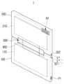
도 1은 본 개시의 일 실시예에 따른 전원 공급 장치의 정면도이다. 도 2는 전원 공급 장치의 펼쳐진 상태, 접힌 상태, 완전히 접힌 상태를 나타내는 측면도이다.1 is a front view of a power supply device according to an embodiment of the present disclosure. 2 is a side view showing a power supply device in an unfolded state, a folded state, and a fully folded state.
도 1 및 도 2를 참조하면, 본 개시의 일 실시예에 따른 전원 공급 장치(1)는 제1 하우징(100), 제2 하우징(200), 힌지 모듈(300) 및 플렉서블 부재(400)를 포함할 수 있다.1 and 2, the
제1 하우징(100)은 AC 전원 입력 포트(P1)를 통하여 AC 전원을 입력받는 제1 회로(110)를 수용할 수 있다. AC 전원 입력 포트(P1)는 제1 하우징(100)의 일측면에 배치될 수 있다. AC 전원 입력 포트(P1)는 외부 상용 전원(예를 들어, 콘센트)과 전선을 통하여 연결될 수 있고, 이에 따라 AC 전원이 AC 전원 입력 포트(P1)를 통하여 제1 회로(110)로 전달될 수 있다.The
제2 하우징(200)은 DC 전원 출력 포트(P2)를 통하여 외부 전자 장치로 DC 전원을 공급하는 제2 회로(210)를 수용할 수 있다. DC 전원 출력 포트(P2)는 외부 전자 장치와 전기적으로 연결될 수 있고, 이에 따라 AC 전원으로부터 변환된 DC 전원이 DC 전원 출력 포트(P2)를 통하여 외부 전자 장치로 전달될 수 있다.The
제1 및 제2 하우징(100, 200)은 대략 직육면체의 형상을 가질 수 있고, 서로 동일한 크기를 가질 수 있으나, 형상 및 크기가 이에 한정되는 것은 아니다.The first and
제1 회로(110) 및 제2 회로(210) 중 적어도 하나는, AC 전원을 DC 전원으로 변환할 수 있다. 즉, 제1 회로(110)가 AC 전원을 DC 전원으로 변환하거나, 제2 회로(210)가 AC 전원을 DC 전원으로 변환하거나, 제1 회로(110) 및 제2 회로(210)가 함께 AC 전원을 DC 전원으로 변환할 수 있다.At least one of the
힌지 모듈(300)은 제1 하우징(100)과 제2 하우징(200)을 회전 가능하게 연결할 수 있다. 즉, 제1 하우징(100)은 힌지 모듈(300)에 회전 가능하게 연결되고, 제2 하우징(200)도 힌지 모듈(300)에 회전 가능하게 연결될 수 있다.The
이에 따라, 제1 및 제2 하우징(100, 200)는, 완전히 펼쳐진 상태, 접힌 상태, 완전히 접힌 상태 중 하나의 상태가 될 수 있다.Accordingly, the first and
플렉서블 부재(400)는 제1 회로(110)와 제2 회로(210)를 전기적으로 연결할 수 있다. 플렉서블 부재(400)는, 금속 와이어 또는 연성 회로 기판(FCB, Flexible Circuit Board)일 수 있다. 이에 따라, 플렉서블 부재(400)는 제1 및 제2 하우징(100, 200)이 폴딩된 상태에서도, 제1 및 제2 회로(110, 210)를 서로 안정적으로 연결할 수 있다.The
힌지 모듈(300)은 힌지 하우징(310) 및 힌지 구조물(320)을 포함할 수 있다. 힌지 하우징(310)은 제1 하우징(100) 및 제2 하우징(200)의 사이에 배치될 수 있다. 힌지 구조물(320)은 힌지 하우징(310)에 수용될 수 있다. 이에 따라, 힌지 구조물(320)은 힌지 하우징(310)에 의해 커버되므로, 외부에서 관찰되지 않을 수 있다.The
플렉서블 부재(400)는 힌지 하우징(310)을 경유할 수 있다. 즉, 플렉서블 부재(400)는 중간 구간이 힌지 하우징(310)내에 수용될 수 있다. 이에 따라, 플렉서블 부재(400)는 힌지 하우징(310)에 의해 커버되므로, 외부에서 관찰되지 않을 수 있다.The
힌지 구조물(320)은, 제1 샤프트(321) 및 제2 샤프트(322)를 포함할 수 있다. 제1 샤프트(321)는 제1 하우징(100)과 힌지 하우징(310)을 회전 가능하게 연결할 수 있다. 제2 샤프트(322)는 제2 하우징(200)과 힌지 하우징(310)을 회전 가능하게 연결할 수 있다. 제2 샤프트(322)는 제1 샤프트(321)와 나란하게 배치될 수 있다.The
제1 하우징(100)은 힌지 하우징(310)에 대하여 제1 샤프트(321)를 기준으로 회전할 수 있고, 제2 하우징(200)은 힌지 하우징(310)에 대하여 제2 샤프트(322)를 기준으로 회전할 수 있다.The
본 개시의 일 실시예에 따른 전원 공급 장치(1)는, 제1 및 제2 하우징(100, 200)이 힌지 모듈(300)에 의하여 폴딩될 수 있고, 제1 및 제2 하우징(100, 200)이 폴딩되어도, 플렉서블 부재(400)에 의해 제1 및 제2 회로(110, 210)가 여전히 전기적으로 안정적으로 연결될 수 있다.In the
이에 따라, 전원 공급 장치(1)는 제1 및 제2 하우징(100, 200)이 완전 펼쳐진 상태이거나, 접힌 상태이거나, 완전히 접힌 상태일 때 모두, 제1 및 제2 회로(110, 210)와 플렉서블 부재(400)에 의해, AC 전원을 DC 전원으로 변환하여 외부 전자 장치에 안정적으로 전달할 수 있다.Accordingly, the
제1 하우징(100) 및 제2 하우징(200) 중 적어도 하나는, 영상 신호를 입력 받는 미디어 포트(미도시)를 포함할 수 있다. 즉, 제1 하우징(100)이 미디어 포트를 포함하거나, 제2 하우징(100)이 미디어 포트를 포함하거나, 제1 하우징(100) 및 제2 하우징(200) 모두 미디어 포트를 포함할 수 있다.At least one of the
미디어 포트를 통하여 수신되는 영상 신호의 규격은 장치의 구현 형태에 대응하여 다양한 방식으로 구성될 수 있다. 예를 들어, 미디어 포트는 HDMI(high definition multimedia interface), 컴포지트(composite) 비디오, 컴포넌트(component) 비디오, 슈퍼 비디오(super video), SCART(Syndicat des Constructeurs d'Appareils Radiorιcepteurs et Televiseurs), USB(universal serial bus) 등에 의하여 유선으로 영상 신호를 수신할 수 있다.The standard of the video signal received through the media port may be configured in various ways corresponding to the implementation form of the device. For example, the media ports are HDMI (high definition multimedia interface), composite video, component video, super video, SCART (Syndicat des Constructeurs d'Appareils Radiorιcepteurs et Televiseurs), USB (universal A video signal can be received by wire through a serial bus) or the like.
또한, 제1 회로(110) 및 제2 회로(210) 중 적어도 하나는, 영상 신호를 디코딩할 수 있다. 즉, 제1 회로(110)가 영상 신호를 디코딩하거나, 제2 회로(210)가 영상 신호를 디코딩하거나, 제1 회로(110) 및 제2 회로(210)가 함께 영상 신호를 디코딩할 수 있다.Also, at least one of the
즉, 제1 및 제2 회로(110, 210) 중 적어도 하나는, 미디어 포트를 통하여 수신된 다양한 종류의 영상 신호를 디스플레이될 수 있는 상태로 디코딩하여 외부 전자 장치로 전송할 수 있다.That is, at least one of the first and
예를 들어, 제1 및 제2 회로(110, 210) 중 적어도 하나는, H.264 디코더일 수 있으나, 이에 한정되는 것은 아니고, MPEG(Moving Picture Experts Group) 디코더 또는 HEVC(High Efficiency Video Codec) 디코더 등 다양한 압축 표준에 따른 디코더로 구현 가능하다.For example, at least one of the first and
이에 따라, 본 개시의 일 실시예에 따른 전원 공급 장치(1)는, 외부 전자 장치에게 DC 전원만 공급하는 것이 아니라, 외부 영상 신호를 디코딩하여 전송할 수 있다.Accordingly, the
도 3 및 도 4는 전원 공급 장치가 AC 전원을 DC 전원으로 변환하는 과정을 나타내는 흐름도이다.3 and 4 are flowcharts illustrating a process in which the power supply converts AC power into DC power.
도 3을 참조하면, AC 전원 입력 포트(P1)는 외부 상용 전원(예를 들어, 콘센트)과 전선을 통하여 연결될 수 있고, 이에 따라 AC 전원이 AC 전원 입력 포트(P1)를 통하여 제1 회로(110)로 전달될 수 있다.Referring to FIG. 3, the AC power input port P1 may be connected to an external commercial power source (eg, an outlet) through a wire, and accordingly, the AC power is supplied to the first circuit (through the AC power input port P1). 110) can be passed on.
제1 회로(110) 및 제2 회로(210) 중 적어도 하나는, AC 전원을 DC 전원으로 변환할 수 있다. 즉, 제1 회로(110)가 AC 전원을 DC 전원으로 변환하거나, 제2 회로(210)가 AC 전원을 DC 전원으로 변환하거나, 제1 회로(110) 및 제2 회로(210)가 함께 AC 전원을 DC 전원으로 변환할 수 있다.At least one of the
플렉서블 부재(400)는 제1 회로(110)와 제2 회로(210)를 전기적으로 연결할 수 있다.The
DC 전원 출력 포트(P2)는 외부 전자 장치와 전기적으로 연결될 수 있고, 이에 따라 AC 전원으로부터 변환된 DC 전원이 DC 전원 출력 포트(P2)를 통하여 외부 전자 장치로 전달될 수 있다.The DC power output port P2 may be electrically connected to an external electronic device, and thus DC power converted from AC power may be transferred to the external electronic device through the DC power output port P2.
도 4를 참조하여, 본 개시의 제1 및 제2 회로(110, 210)의 구체적인 역할 및 기능을 살펴본다. 도 4를 참조하면, 전원 공급 장치(1)는 정류부(P10), 컨버터(P20)를 포함할 수 있다.Referring to FIG. 4 , detailed roles and functions of the first and
전원 공급 장치(1)의 정류부(P10)는 EMI 필터(P11), PFC 회로(P12)를 포함할 수 있다. EMI 필터(P11)는 입력된 상용 AC 전원을 정류 및 평활하여 일정 레벨의 직류 전원으로 출력한다. 정류를 위해 반파 또는 전파 정류 회로가 사용될 수 있고, 평활을 위해 커패시터가 정류회로의 출력단에 병렬로 연결될 수도 있다.The rectifier P10 of the
전원 공급 장치(1)의 컨버터(P20)는 정류부(P10)에서 정류된 DC 전원을 기설정된 세기의 전원으로 컨버팅할 수 있다. 컨버터(P20)는 절연형으로, 1차측(입력)과 2차측(출력)이 Trans로 절연되어 있는 형태일 수 있다. 여기서, Trans는 Core(코어, 자심)에 1차 권선과 2차 권선을 감은것으로, 1차 권선에 전류 변화가 발생하면 Core를 관통하는 자속 변화에 의해 2차 권선에도 유도기전력이 발생하여 유도전류가 흐른다. The converter P20 of the
도 5는 전원 공급 장치의 완전히 접힌 상태를 나타내는 측면도이다. 도 5를 참조하면, 전원 공급 장치(1)는 제1 기판(120) 및 제2 기판(220)을 더 포함할 수 있다.5 is a side view showing the fully folded state of the power supply. Referring to FIG. 5 , the
제1 기판(120)은, 일면(121)에 제1 회로(110)가 배치될 수 있다. 제2 기판(220)은, 일면(221)에 제2 회로(210)가 배치될 수 있다. 제1 회로(110)는 제1 기판(120)의 일면(121)에 인쇄될 수 있고, 제2 회로(210)는 제2 기판(220)의 일면(221)에 인쇄될 수있다.The
제1 및 제2 하우징(100, 200)이 완전히 접힌 상태에서, 제1 기판(120)의 일면(121)은 제2 기판(220)의 타면(222)과 마주하도록 배치될 수 있다.When the first and
이에 따라, 제1 및 제2 하우징(100, 200)이 완전히 접힌 상태에서, 제1 회로(110)와 제2 회로(210)는 서로 멀리 이격 배치되므로, 전원 공급 장치(1)에서 발생하는 열이 외부로 용이하게 발산될 수 있다.Accordingly, in a state in which the first and
전원 공급 장치(1)는, 제1 자성 부재(130) 및 제2 자성 부재(230)를 더 포함할 수 있다.The
제1 및 제2 하우징(100, 200)이 완전히 접힌 상태에서, 제1 하우징(100)의 일면(101)은 제2 하우징(200)의 일면(201)과 마주하도록 배치될 수 있다. 제1 자성 부재(130)는 제1 하우징(100)에 일면(101)에 배치될 수 있다. 제2 자성 부재(230)는 제2 하우징(200)의 일면(201) 중 제1 자성 부재(130)와 대응되는 위치에 배치될 수 있다.When the first and
또한, 제2 자성 부재(230)는 제1 자성 부재(130)와 반대되는 극성을 가질 수 있다. 즉, 제1 및 제2 하우징(100, 200)이 완전히 접힌 상태에서, 제1 및 제2 하우징(100, 200)은 제1 및 제2 자성 부재(130, 230)의 자기적 인력에 의해 서로 끌어 당길 수 있다.Also, the second
이에 따라, 사용자는 완전히 접힌 상태의 제1 및 제2 하우징(100, 200)에 소정 이상의 힘을 가하여야 제1 및 제2 하우징(100, 200)을 펼칠 수 있으므로, 제1 및 제2 하우징(100, 200)은 완전히 접힌 상태에서 의도치 않게 펼쳐지지 않을 수 있고, 사용자는 부드러운 사용감으로 제1 및 제2 하우징(100, 200)을 접거나 펼칠 수 있다.Accordingly, since the user can unfold the first and
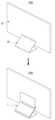
도 6 및 도 7은 스탠드형 전자 장치에 전원 공급 장치가 장착되는 구조를 설명하는 도면이다.6 and 7 are views illustrating a structure in which a power supply device is mounted in a stand-type electronic device.
도 6 및 도 7을 참조하면, 본 개시의 일 실시예에 따른 전자 장치(1000)는, 본체(10) 및 전원 공급 장치(1)를 포함할 수 있다.Referring to FIGS. 6 and 7 , an
본 개시의 다양한 실시예에 따른 전자 장치(1000)는, 이미지 표시 기능을 포함하는 전자 장치, 가구(furniture) 또는 건물/구조물의 일부일 수 있다. 예를 들어, 전자 장치(1)는 텔레비전, DVD(digital video disk)플레이어, 스마트 폰(smartphone), 데스크탑 PC(desktop personal computer), 태블릿 PC(tablet personal computer), 랩탑 PC(laptop personal computer), PDA(personal digital assistant), PMP(portable multimedia player), 모바일 의료기기, 카메라(camera), 웨어러블 장치(wearable device), TV 박스(예를 들면, 예를 들면, 삼성 HomeSyncTM, 애플TVTM, 또는 구글 TVTM), 게임 콘솔(game consoles), 전자 보드(electronic board), 전자 사인 입력장치(electronic signature receiving device), 프로젝터(projector), 또는 각종 계측기기(예: 수도, 전기, 가스, 또는 전파 계측 기기 등) 중 적어도 하나를 포함할 수 있다.The
또한, 본 개시의 일 실시예에 따른 전자 장치(1000)는, 자체적으로 발광하는 스크린 장치뿐만 아니라, 프로젝터(projector)로부터 입사한 빛을 반사하는 반사형 스크린 장치에도 적용될 수 있다.In addition, the
본체(10)는 전면에 디스플레이 패널(미도시)이 배치될 수 있다. 디스플레이 패널은 사용자에게 각종 콘텐츠(예: 텍스트, 이미지, 비디오, 아이콘 및 심볼 등)를 표시할 수 있다. 디스플레이 패널은 예를 들면, 액정 디스플레이(liquid crystal display(LCD)), 발광 다이오드(light-emitting diode(LED)) 디스플레이, 유기 발광 다이오드(organic light-emitting diode(OLED)) 디스플레이, 마이크로 전자기계 시스템(microelectromechanical systems(MEMS)) 디스플레이, 전자종이(electronic paper) 디스플레이, 또는 표시부가 구부러지거나 휘어지는 플렉서블 디스플레이(flexible display)를 포함할 수 있다.A display panel (not shown) may be disposed on the front surface of the
전원 공급 장치(1)는 본체(10)와 연결될 수 있다. 즉, 전원 공급 장치(1)는 본체(10)와 전기적으로 연결되어, 본체(10)에 DC 전원을 공급할 수 있다.The
이에 따라, AC/DC 전원 변환 회로가 본체(10)에 내장되는 것이 아니라, 전원 공급 장치(1)에 외장되므로, 전자 장치(1000)의 본체(10)는 얇은 두께를 가져서 컴팩트한 외관을 가질 수 있다.Accordingly, since the AC/DC power conversion circuit is not built into the
본체(10)는, 배면(11)에 DC 전원 입력 포트(P3)를 포함할 수 있다. DC 전원 입력 포트(P3)는 전원 공급 장치(1)의 DC 전원 출력 포트(P2)와 전기적으로 연결될 수 있다.The
DC 전원 출력 포트(P2)및 DC 전원 입력 포트(P3)는, 서로 맞물리는 형상을 가질 수 있다. 예를 들어, DC 전원 출력 포트(P2)는 함몰된 구조를 갖고, DC 전원 입력 포트(P3)는 돌출된 구조를 가질 수 있다. 반대로, DC 전원 출력 포트(P2)는 돌출된 구조를 갖고, DC 전원 입력 포트(P3)는 함몰된 구조를 가질 수 있다.The DC power output port P2 and the DC power input port P3 may have shapes that engage with each other. For example, the DC power output port P2 may have a recessed structure, and the DC power input port P3 may have a protruding structure. Conversely, the DC power output port P2 may have a protruding structure, and the DC power input port P3 may have a recessed structure.
이에 따라, DC 전원 출력 포트(P2)와 DC 전원 입력 포트(P3)는 서로 직접적으로 체결될 수 있다. 다만, DC 전원 출력 포트(P2)및 DC 전원 입력 포트(P3)의 체결 구조가 이에 한정 되는 것은 아니고, DC 전원 출력 포트(P2)및 DC 전원 입력 포트(P3)는 서로 이격 배치되고, 그 사이를 와이어 부재(40)가 전기적으로 연결할 수도 있다.Accordingly, the DC power output port P2 and the DC power input port P3 may be directly engaged with each other. However, the fastening structure of the DC power output port (P2) and the DC power input port (P3) is not limited to this, and the DC power output port (P2) and the DC power input port (P3) are spaced apart from each other and arranged therebetween. The
전자 장치(1000)는, 본체(10)를 지지하는 스탠드(20)를 더 포함할 수 있다. 즉, 도 6 및 도 7에 도시된 전자 장치(1000)는 스탠드형의 전자 장치일 수 있다.The
전원 공급 장치(1)의 제1 하우징(100)은 스탠드(20)의 배면(23)에 장착될 수 있다. 또한, 전원 공급 장치(1)의 제2 하우징(200)은 본체(10)의 배면(11)에 장착될 수 있다.The
즉, 전자 장치(1000)를 전방에서 바라보았을 때, 전원 공급 장치(1)는 본체(10) 및 스탠드(20)에 의해 가려지므로, 전자 장치(1000)는 컴팩트한 외관을 가질 수 있다.That is, when the
또한, 제1 하우징(100)의 너비는, 스탠드(20)의 너비와 같거나 스탠드(20)의 너비보다 작을 수 있다. 이에 따라, 제1 하우징(100)이 스탠드(20)에 의해 완벽히 가려지게 되므로, 전자 장치(1000)는 더욱 컴팩트한 외관을 가질 수 있다.Also, the width of the
스탠드(20)는, 배면(23)에 돌출 형성된 제1 고정 돌기(24)를 포함할 수 있다. 제1 고정 돌기(24)는 후크의 형상을 가질 수 있다. 제1 하우징(100)은, 제1 고정 돌기(24)와 맞물리는 형상을 갖는 고정 홈(140)을 포함할 수 있다.The
이에 따라, 전원 공급 장치(1)는 스탠드(20)에 안정적으로 고정될 수 있다. 다만, 이에 한정되는 것은 아니고, 스탠드(20)의 배면(23)에 함몰 구조가 형성되고, 제1 하우징(100)에 돌출 구조가 형성되어 서로 맞물릴 수도 있다.Accordingly, the
또한, 스탠드(20)와 제1 하우징(100)은, 상술한 바와 같이 기구적으로 결합될 수 있을 뿐만 아니라, 철판, 플라스틱 등으로 형성된 상대 극성 사출물의 자력에 의해 고정될 수도 있다.In addition, the
스탠드(20)는, 바닥에 수평하게 배치되는 제1 지지 부재(21) 및 제1 지지 부재(21)와 본체(10)의 배면(11)을 연결하는 제2 지지 부재(22)를 포함할 수 있다. 제1 지지 부재(21)는 바닥과 접하고, 제2 지지 부재(22)는 제1 지지 부재(21)의 후단으로부터 전방으로 상향 경사지게 연장되어 본체(10)의 배면과 연결될 수 있다.The
본체(10)와 제2 지지 부재(22)의 사이각은, 제1 하우징(100)과 제2 하우징(200)의 사이각(t)과 동일할 수 있다. 즉, 전원 공급 장치(1)의 제1 및 제2 하우징(100, 200)은, 본체(10) 및 스탠드(20)에 대응하는 형상으로 접힌 상태로 본체(10)에 DC 전원을 안정적으로 공급할 수 있다.The angle between the
본 개시의 일 실시예에 따른 전원 공급 장치(1)는 제1 및 제2 하우징(100, 200)이 다양한 각도로 접힐 수 있으므로, 다양한 형상의 스탠드형 전자 장치(1000)에 적용될 수 있다.Since the first and
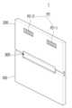
도 8 및 도 9은 벽걸이형 전자 장치에 전원 공급 장치가 장착되는 구조를 설명하는 도면이다.8 and 9 are views illustrating a structure in which a power supply device is mounted in a wall-mounted electronic device.
전자 장치(1000)는, 본체(10)를 벽(미도시)에 고정시키는 월 마운트(30)를 더 포함할 수 있다. 월 마운트(30)는 본체(10)의 배면(11)에 배치되고, 브라켓, 나사등을 포함하여, 본체(10)를 벽에 고정시킬 수 있다.The
제1 및 제2 하우징(100, 200)은 본체(10)의 배면(11)에 장착될 수 있다. 예를 들어, 제1 및 제2 하우징(100, 200)은 완전히 펴진 상태로 본체(10)의 배면(11)과 접할 수 있다.The first and
본체(10)는 배면(11)에 돌출 형성된 제2 고정 돌기(12)를 포함할 수 있다. 제2 고정 돌기(12)는 후크의 형상을 가질 수 있으나, 형상이 이에 한정되는 것은 아니다.The
제1 하우징(100)은, 제2 고정 돌기(12)와 맞물리는 형상을 갖는 고정 홈(140)을 포함할 수 있다. 이에 따라, 전원 공급 장치(1)는 본체(10)에 안정적으로 고정될 수 있다. 다만, 이에 한정되는 것은 아니고, 본체(10)의 배면(11)에 함몰 구조가 형성되고, 제2 하우징(200)에 돌출 구조가 형성되어 서로 맞물릴 수도 있다.The
또한, 본체(10)와 제1 하우징(100)은, 상술한 바와 같이 기구적으로 결합될 수 있을 뿐만 아니라, 철판, 플라스틱 등으로 형성된 상대 극성 사출물의 자력에 의해 고정될 수도 있다.In addition, the
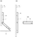
도 10 내지 도 12는 복수의 DC 전원 출력 포트가 형성된 전원 공급 장치가 전자 장치에 장착되는 구조를 설명하는 도면이다.10 to 12 are diagrams illustrating a structure in which a power supply device having a plurality of DC power output ports is mounted on an electronic device.
전원 공급 장치(1)는 제2 하우징(200)에 형성된 DC 전원 출력 포트(P2)를 포함할 수 있고, DC 전원 출력 포트(P2)는 전자 장치(1000)와 전기적으로 연결될 수 있고, 이에 따라 AC 전원으로부터 변환된 DC 전원이 DC 전원 출력 포트(P2)를 통하여 전자 장치(1000)로 전달될 수 있다.The
또한, DC 전원 출력 포트(P2)는, 제2 하우징(200)의 일면에 배치되는 복수의 DC 전원 출력 포트(P2-1, P2-2)를 포함할 수 있다. 구체적으로, DC 전원 출력 포트(P2)는 스탠드형 포트(P2-1) 및 벽걸이형 포트(P2-2)를 포함할 수 있다.In addition, the DC power output port P2 may include a plurality of DC power output ports P2 - 1 and P2 - 2 disposed on one surface of the
스탠드형 포트(P2-1)는 스탠드형 전자 장치(1000)와 연결될 수 있고, 벽걸이형 포트(P2-2)는 벽걸이형 전자 장치(1000)와 연결될 수 있다. 스탠드형 포트(P2-1) 및 벽걸이형 포트(P2-2)는 제2 하우징(200)의 동일한 일면에 배치될 수 있다.The stand-type port P2-1 may be connected to the stand-type
사용자는, 전자 장치(1000)가 도 11의 스탠드형에서 도 12의 벽걸이형으로 바뀜에 따라, 전원 공급 장치(1)가 본체(10)에 가려져 전방에서 보이지 않도록, 도 11의 전원 공급 장치(1)를 도 12의 전원 공급 장치(1)로 180도 회전하여 전자 장치(1)에 연결할 수 있다.As the
이에 따라, 전원 공급 장치(1)는 전자 장치(1000)의 종류에 상관 없이 전방에서 보이지 않게 되므로, 전자 장치(1000)는 컴팩트한 외관을 가질 수 있다.Accordingly, since the
전자 장치(1000)는, 제2 하우징(200)의 일면에 슬라이딩 가능하게 배치되어, 복수의 DC 전원 출력 포트(P2-1, P2-2) 중 하나만 선택적으로 노출시키는 도어 부재(240)를 더 포함할 수 있다.The
도어 부재(240)는, 전자 장치(1000)가 스탠드형인 경우, 벽걸이형 포트(P2-2)를 가리고 스탠드형 포트(P2-1)를 노출시킬 수 있다. 또한, 도어 부재(240)는, 전자 장치(1000)가 벽걸이형인 경우, 스탠드형 포트(P2-1)를 가리고 벽걸이형 포트(P2-2)를 노출시킬 수 있다.When the
이에 따라, 사용자는 혼동하지 않고 복수의 DC 전원 출력 포트(P2-1, P2-2) 중 전자 장치(1000)의 종류에 대응되는 포트를 전자 장치(1000)에 정확히 연결할 수 있다.Accordingly, the user can accurately connect the port corresponding to the type of the
도 13은 전원 공급 장치가 와이어 부재를 통하여 전자 장치와 연결된 구조를 설명하는 도면이다. 도 13을 참조하면, 전원 공급 장치(1)는 본체(10)와 이격된 곳에 배치되고, 와이어 부재(40)를 통하여 본체(10)의 DC 전원 입력 포트(P3)와 전기적으로 연결될 수 있다.13 is a diagram explaining a structure in which a power supply device is connected to an electronic device through a wire member. Referring to FIG. 13 , the
즉, 본체(10)는 배면(11)에 DC 전원을 입력받는 DC 전원 입력 포트(P3)를 포함하고, 전자 장치(1000)는, DC 전원 출력 포트(P2)와 DC 전원 입력 포트(P3)를 전기적으로 연결하는 와이어 부재(40)를 더 포함할 수 있다.That is, the
구체적으로, 전원 공급 장치(1)는 AC 전원 입력 포트(P1)에 연결된 외부 전선(W)을 통하여 AC 전원을 공급받고, DC 전원으로 변환한 후, DC 전원 출력 포트(P2)에 연결된 와이어 부재(40)를 통하여 본체(10)의 DC 전원 입력 포트(P3)롤 DC 전원을 전달할 수 있다.Specifically, the
이 때, 전원 공급 장치(1)는 완전히 접힌 상태일 수 있으나, 이에 한정되는 것은 아니고, 완전히 펼친 상태이거나 일부만 접힌 상태일 수도 있다.At this time, the
전원 공급 장치(1)와 본체(10)가 와이어 부재(40)를 통하여 연결됨에 따라, 전원 공급 장치(1) 및 본체(10)에 돌출 구조 및 함몰 구조가 형성되지 않을 수 있다. 이러한 구조는, 상술한 스탠드형 전자 장치(1000)나 벽걸이형 전자 장치(1000)에도 적용될 수 있다.As the
도 14는 전원 공급 장치를 둘러싸는 커버 부재의 구조를 설명하는 도면이다. 도 14를 참조하면, 전자 장치(1000)는, 전원 공급 장치(1)를 둘러싸는 커버 부재(50)를 더 포함할 수 있다. 커버 부재(50)는 본체(10), 스탠드(20), 전원 공급 장치(1) 중 적어도 한 곳에 고정될 수 있으나, 이에 한정되는 것은 아니다. 커버 부재(50)는 전원 공급 장치(1)의 포트에 대응하는 위치에 홀이 형성되어, 전선이나 와이어 등에 의한 접속을 방해하지 않을 수 있다.14 is a diagram explaining the structure of a cover member enclosing a power supply device. Referring to FIG. 14 , the
커버 부재(50)는 전원 공급 장치(1)를 가려서 외부로 노출되지 않게 할 수 있다. 커버 부재(50)는 플라스틱으로 형성될 수 있으나, 이에 한정되는 것은 아니다. 또한, 커버 부재(50)는 외면에 그림이나 무늬가 형성될 수 있다. 이에 따라, 전자 장치(1000)는 전원 공급 장치(1)가 외부로 노출되지 않으면서, 커버 부재(50)에 의해 수려한 외관을 가질 수 있다.The
이상에서는 본 개시의 바람직한 실시예에 대해서 도시하고, 설명하였으나, 본 개시는 상술한 특정의 실시예에 한정되지 아니하며, 청구범위에서 청구하는 본 개시의 요지를 벗어남이 없이 당해 개시가 속하는 기술분야에서 통상의 지식을 가진자라면 누구든지 다양한 변형 실시가 가능한 것은 물론이고, 그와 같은 변경은 청구범위 기재의 범위 내에 있게 된다.In the above, preferred embodiments of the present disclosure have been shown and described, but the present disclosure is not limited to the specific embodiments described above, and in the technical field to which the disclosure belongs without departing from the gist of the present disclosure claimed in the claims. Anyone skilled in the art can make various modifications, of course, and such changes are within the scope of the claims.
1: 전원 공급 장치10: 본체
20: 스탠드30: 월 마운트
40: 와이어 부재50: 커버 부재
100: 제1 하우징200: 제2 하우징
300: 힌지 모듈400: 플렉서블 부재
1000: 전자 장치1: power supply 10: body
20: stand 30: wall mount
40: wire member 50: cover member
100: first housing 200: second housing
300: hinge module 400: flexible member
1000: electronic device
Claims (20)
Translated fromKorean상기 본체와 전기적으로 연결되는 전원 공급 장치;를 포함하고,
상기 전원 공급 장치는,
AC 전원을 입력받는 제1 회로를 수용하는 제1 하우징;
상기 본체로 DC 전원을 공급하는 제2 회로를 수용하는 제2 하우징;
상기 제1 하우징과 상기 제2 하우징을 회전 가능하게 연결하는 힌지 모듈; 및
상기 제1 회로와 상기 제2 회로를 전기적으로 연결하는 플렉서블 부재;를 포함하는 전자 장치.main body; and
Including; power supply device electrically connected to the main body,
The power supply,
a first housing accommodating a first circuit receiving AC power;
a second housing accommodating a second circuit supplying DC power to the main body;
a hinge module rotatably connecting the first housing and the second housing; and
and a flexible member electrically connecting the first circuit and the second circuit.
상기 플렉서블 부재는, 금속 와이어 또는 연성 회로 기판인 전자 장치.According to claim 1,
The electronic device of claim 1, wherein the flexible member is a metal wire or a flexible circuit board.
상기 힌지 모듈은,
상기 제1 및 제2 하우징의 사이에 배치되는 힌지 하우징 및
상기 힌지 하우징에 수용되는 힌지 구조물을 포함하는 전자 장치.According to claim 1,
The hinge module,
a hinge housing disposed between the first and second housings; and
An electronic device including a hinge structure accommodated in the hinge housing.
상기 플렉서블 부재는 힌지 하우징를 경유하는 전자 장치.According to claim 3,
The flexible member is an electronic device via a hinge housing.
상기 힌지 구조물은,
상기 제1 하우징과 상기 힌지 하우징을 회전 가능하게 연결하는 제1 샤프트 및
상기 제2 하우징과 상기 힌지 하우징을 회전 가능하게 연결하고, 상기 제1 샤프트와 나란하게 배치되는 제2 샤프트를 포함하는 전자 장치.According to claim 3,
The hinge structure,
a first shaft rotatably connecting the first housing and the hinge housing; and
and a second shaft rotatably connecting the second housing and the hinge housing and disposed parallel to the first shaft.
상기 전원 공급 장치는,
일면에 상기 제1 회로가 배치되는 제1 기판; 및
일면에 상기 제2 회로가 배치되는 제2 기판;을 더 포함하고,
상기 제1 및 제2 하우징이 완전히 접힌 상태에서, 상기 제1 기판의 일면은 상기 제2 기판의 타면과 마주하도록 배치되는 전자 장치.According to claim 1,
The power supply,
a first substrate on one surface of which the first circuit is disposed; and
A second substrate on one surface of which the second circuit is disposed; further comprising,
The electronic device of claim 1 , wherein one surface of the first substrate faces the other surface of the second substrate when the first and second housings are fully folded.
상기 제1 및 제2 하우징이 완전히 접힌 상태에서, 상기 제1 하우징의 일면은 상기 제2 하우징의 일면과 마주하도록 배치되고,
상기 전원 공급 장치는,
상기 제1 하우징에 일면에 배치되는 제1 자성 부재; 및
상기 제2 하우징의 일면 중 상기 제1 자성 부재와 대응되는 위치에 배치되고, 상기 제1 자성 부재와 반대되는 극성을 갖는 제2 자성 부재;를 더 포함하는 전자 장치.According to claim 1,
When the first and second housings are completely folded, one surface of the first housing is disposed to face one surface of the second housing,
The power supply,
a first magnetic member disposed on one surface of the first housing; and
The electronic device further includes a second magnetic member disposed at a position corresponding to the first magnetic member on one surface of the second housing and having a polarity opposite to that of the first magnetic member.
상기 제1 및 제2 하우징 중 적어도 하나는, 영상 신호를 입력 받는 미디어 포트를 포함하고,
상기 제1 및 제2 회로 중 적어도 하나는, 상기 영상 신호를 디코딩하는 전자 장치.According to claim 1,
At least one of the first and second housings includes a media port for receiving an image signal;
At least one of the first and second circuits decodes the video signal.
상기 제2 하우징은, 일면에 배치되는 복수의 DC 전원 출력 포트를 포함하는 전자 장치.According to claim 1,
The second housing includes a plurality of DC power output ports disposed on one side of the electronic device.
상기 전원 공급 장치는,
상기 제2 하우징의 일면에 슬라이딩 가능하게 배치되어, 상기 복수의 DC 전원 출력 포트 중 하나만 선택적으로 노출시키는 도어 부재;를 더 포함하는 전자 장치.According to claim 9,
The power supply,
The electronic device further includes a door member slidably disposed on one surface of the second housing and selectively exposing only one of the plurality of DC power output ports.
상기 제1 및 제2 회로 중 적어도 하나는, AC 전원을 DC 전원으로 변환하는 전자 장치.According to claim 1,
At least one of the first and second circuits converts AC power to DC power.
상기 본체는, 배면에 상기 제2 하우징의 DC 전원 출력 포트와 전기적으로 연결되는 DC 전원 입력 포트를 포함하고,
상기 DC 전원 출력 포트 및 상기 DC 전원 입력 포트는, 서로 맞물리는 형상을 갖는 전자 장치.According to claim 1,
The main body includes a DC power input port electrically connected to the DC power output port of the second housing on the rear surface,
The electronic device of claim 1 , wherein the DC power output port and the DC power input port have shapes interlocking with each other.
상기 제2 하우징의 DC 전원 출력 포트와 상기 본체의 DC 전원 입력 포트를 전기적으로 연결하는 와이어 부재;를 더 포함하는 전자 장치.According to claim 1,
The electronic device further includes a wire member electrically connecting the DC power output port of the second housing and the DC power input port of the main body.
상기 본체를 지지하는 스탠드;를 더 포함하고,
상기 제1 하우징은 상기 스탠드의 배면에 장착되고,
상기 제2 하우징은 상기 본체의 배면에 장착되는 전자 장치.According to claim 1,
A stand supporting the main body; further comprising,
The first housing is mounted on the rear surface of the stand,
The second housing is mounted on a rear surface of the main body.
상기 스탠드는, 배면에 돌출 형성된 제1 고정 돌기를 포함하고,
상기 제1 하우징은, 상기 제1 고정 돌기와 맞물리는 형상을 갖는 고정 홈을 포함하는 전자 장치.According to claim 14,
The stand includes a first fixing protrusion protruding from the rear surface,
The electronic device of claim 1 , wherein the first housing includes a fixing groove having a shape engaged with the first fixing protrusion.
상기 제1 하우징의 너비는, 상기 스탠드의 너비와 같거나 상기 스탠드의 너비보다 작은 전자 장치.According to claim 14,
The electronic device of claim 1 , wherein a width of the first housing is equal to or smaller than a width of the stand.
상기 스탠드는,
바닥에 수평하게 배치되는 제1 지지 부재 및
상기 제1 지지 부재와 상기 본체의 배면을 연결하는 제2 지지 부재를 포함하고,
상기 본체와 상기 제2 지지 부재의 사이각은, 상기 제1 하우징과 상기 제2 하우징의 사이각과 동일한 전자 장치.According to claim 14,
the stand,
A first support member disposed horizontally on the floor and
A second support member connecting the first support member and the rear surface of the body,
An angle between the main body and the second support member is equal to an angle between the first housing and the second housing.
상기 본체를 벽에 고정시키는 월 마운트;를 더 포함하고,
상기 제1 및 제2 하우징은 상기 본체의 배면에 장착되는 전자 장치.According to claim 1,
A wall mount fixing the main body to a wall; further comprising,
The first and second housings are mounted on a rear surface of the main body.
상기 본체는 배면에 돌출 형성된 제2 고정 돌기를 포함하고,
상기 제1 하우징은, 상기 제2 고정 돌기와 맞물리는 형상을 갖는 고정 홈을 포함하는 전자 장치.According to claim 18,
The main body includes a second fixing protrusion protruding from the rear surface,
The electronic device of claim 1 , wherein the first housing includes a fixing groove having a shape engaged with the second fixing protrusion.
상기 전원 공급 장치를 둘러싸는 커버 부재;를 더 포함하는 전자 장치.According to claim 1,
The electronic device further comprising a cover member surrounding the power supply device.
Priority Applications (3)
| Application Number | Priority Date | Filing Date | Title |
|---|---|---|---|
| KR1020210150034AKR20230064444A (en) | 2021-11-03 | 2021-11-03 | Electronic apparatus |
| PCT/KR2022/013203WO2023080415A1 (en) | 2021-11-03 | 2022-09-02 | Electronic apparatus |
| US17/967,547US11763703B2 (en) | 2021-11-03 | 2022-10-17 | Electronic apparatus |
Applications Claiming Priority (1)
| Application Number | Priority Date | Filing Date | Title |
|---|---|---|---|
| KR1020210150034AKR20230064444A (en) | 2021-11-03 | 2021-11-03 | Electronic apparatus |
Publications (1)
| Publication Number | Publication Date |
|---|---|
| KR20230064444Atrue KR20230064444A (en) | 2023-05-10 |
Family
ID=86241209
Family Applications (1)
| Application Number | Title | Priority Date | Filing Date |
|---|---|---|---|
| KR1020210150034APendingKR20230064444A (en) | 2021-11-03 | 2021-11-03 | Electronic apparatus |
Country Status (2)
| Country | Link |
|---|---|
| KR (1) | KR20230064444A (en) |
| WO (1) | WO2023080415A1 (en) |
Family Cites Families (5)
| Publication number | Priority date | Publication date | Assignee | Title |
|---|---|---|---|---|
| KR20010108901A (en)* | 2000-06-01 | 2001-12-08 | 박종섭 | Structure of mounting the power of LCD monitor |
| KR200467441Y1 (en)* | 2011-07-06 | 2013-06-14 | 성부현 | Wireless charger and cradle combination device for portable terminal |
| KR20250083577A (en)* | 2014-02-28 | 2025-06-10 | 가부시키가이샤 한도오따이 에네루기 켄큐쇼 | Electronic device |
| IT201600103458A1 (en)* | 2016-10-14 | 2018-04-14 | Luca Gerardi | MODULAR PROCESSING SYSTEM |
| KR20190114863A (en)* | 2018-03-30 | 2019-10-10 | 유상규 | Folding type portable device having flexible display |
- 2021
- 2021-11-03KRKR1020210150034Apatent/KR20230064444A/enactivePending
- 2022
- 2022-09-02WOPCT/KR2022/013203patent/WO2023080415A1/ennot_activeCeased
Also Published As
| Publication number | Publication date |
|---|---|
| WO2023080415A1 (en) | 2023-05-11 |
Similar Documents
| Publication | Publication Date | Title |
|---|---|---|
| JP6720363B2 (en) | Video media streaming device | |
| JP4999916B2 (en) | Outlet device and connection method thereof | |
| US8832469B2 (en) | AC-powered in-wall computing device with power-line networking capabilities | |
| KR102754838B1 (en) | Display apparatus and method of controlling the same | |
| TWI516127B (en) | Display device with detachable speaker modules | |
| US8671292B2 (en) | Ethernet powered computing device and system | |
| CN113163140B (en) | Display device | |
| US9164363B2 (en) | Projection apparatus | |
| JP2018521532A (en) | Audio media streaming device | |
| CN101576704A (en) | Portable projector | |
| CN202815404U (en) | Multifunctional micro projection lamps | |
| US20150195492A1 (en) | Conference room audio/video cable interface device | |
| KR20230064444A (en) | Electronic apparatus | |
| US11763703B2 (en) | Electronic apparatus | |
| US20220078368A1 (en) | Display apparatus | |
| US20220246084A1 (en) | Display apparatus | |
| CN105485492B (en) | Display device | |
| KR102355698B1 (en) | Multi-functional display device | |
| CN203276122U (en) | Socket type cloud terminal | |
| CN207250105U (en) | A kind of advertisement machine of double control mainboard and double screen | |
| CN106598154A (en) | Interactive intelligent flat plate and camera device thereof | |
| CN114067686B (en) | Display device | |
| CN201226554Y (en) | Integrated machine of television and computer | |
| CN104980723A (en) | Flat panel projection system with modular external functions | |
| CN202257360U (en) | Remote-controllable notebook computer with miniature projector and television box |
Legal Events
| Date | Code | Title | Description |
|---|---|---|---|
| PA0109 | Patent application | Patent event code:PA01091R01D Comment text:Patent Application Patent event date:20211103 | |
| PG1501 | Laying open of application | ||
| A201 | Request for examination | ||
| PA0201 | Request for examination | Patent event code:PA02012R01D Patent event date:20241104 Comment text:Request for Examination of Application |