KR20230062816A - Methods and apparatus enabling coupling of an electronic unit to a base unit of a continuous analyte monitoring device - Google Patents
Methods and apparatus enabling coupling of an electronic unit to a base unit of a continuous analyte monitoring deviceDownload PDFInfo
- Publication number
- KR20230062816A KR20230062816AKR1020237005979AKR20237005979AKR20230062816AKR 20230062816 AKR20230062816 AKR 20230062816AKR 1020237005979 AKR1020237005979 AKR 1020237005979AKR 20237005979 AKR20237005979 AKR 20237005979AKR 20230062816 AKR20230062816 AKR 20230062816A
- Authority
- KR
- South Korea
- Prior art keywords
- electronic unit
- carrier
- arm
- unit
- base unit
- Prior art date
- Legal status (The legal status is an assumption and is not a legal conclusion. Google has not performed a legal analysis and makes no representation as to the accuracy of the status listed.)
- Pending
Links
- 230000008878couplingEffects0.000titleclaimsabstractdescription73
- 238000010168coupling processMethods0.000titleclaimsabstractdescription73
- 238000005859coupling reactionMethods0.000titleclaimsabstractdescription73
- 239000012491analyteSubstances0.000titleclaimsabstractdescription66
- 238000000034methodMethods0.000titleclaimsabstractdescription32
- 238000012806monitoring deviceMethods0.000titledescription3
- 230000014759maintenance of locationEffects0.000claimsabstractdescription59
- 239000012190activatorSubstances0.000claimsabstractdescription58
- 238000012544monitoring processMethods0.000claimsabstractdescription37
- 230000004044responseEffects0.000claimsabstractdescription12
- 238000005452bendingMethods0.000claimsdescription3
- WQZGKKKJIJFFOK-GASJEMHNSA-NGlucoseNatural productsOC[C@H]1OC(O)[C@H](O)[C@@H](O)[C@@H]1OWQZGKKKJIJFFOK-GASJEMHNSA-N0.000description18
- 239000008103glucoseSubstances0.000description18
- 238000003780insertionMethods0.000description15
- 230000037431insertionEffects0.000description15
- 239000010410layerSubstances0.000description7
- 238000005538encapsulationMethods0.000description5
- -1polypropylenePolymers0.000description5
- 230000000717retained effectEffects0.000description5
- 239000000758substrateSubstances0.000description5
- 239000004944Liquid Silicone RubberSubstances0.000description4
- 239000004954PolyphthalamideSubstances0.000description4
- 229920001903high density polyethylenePolymers0.000description4
- 239000004700high-density polyethyleneSubstances0.000description4
- 229920001684low density polyethylenePolymers0.000description4
- 239000004702low-density polyethyleneSubstances0.000description4
- 239000000463materialSubstances0.000description4
- 239000002184metalSubstances0.000description4
- 229920006375polyphtalamidePolymers0.000description4
- 229920002379silicone rubberPolymers0.000description4
- 238000007920subcutaneous administrationMethods0.000description4
- 229920002725thermoplastic elastomerPolymers0.000description4
- 230000007704transitionEffects0.000description4
- 239000004677NylonSubstances0.000description3
- 239000004695Polyether sulfoneSubstances0.000description3
- 239000004743PolypropyleneSubstances0.000description3
- DHKHKXVYLBGOIT-UHFFFAOYSA-Nacetaldehyde Diethyl AcetalNatural productsCCOC(C)OCCDHKHKXVYLBGOIT-UHFFFAOYSA-N0.000description3
- 125000002777acetyl groupChemical class[H]C([H])([H])C(*)=O0.000description3
- 239000004676acrylonitrile butadiene styreneSubstances0.000description3
- 239000008280bloodSubstances0.000description3
- 210000004369bloodAnatomy0.000description3
- 210000003722extracellular fluidAnatomy0.000description3
- 238000005259measurementMethods0.000description3
- 229920001778nylonPolymers0.000description3
- 229920003023plasticPolymers0.000description3
- 239000004033plasticSubstances0.000description3
- 229920002492poly(sulfone)Polymers0.000description3
- 239000004417polycarbonateSubstances0.000description3
- 229920000515polycarbonatePolymers0.000description3
- 229920006393polyether sulfonePolymers0.000description3
- 229920001155polypropylenePolymers0.000description3
- 230000008569processEffects0.000description3
- XECAHXYUAAWDEL-UHFFFAOYSA-Nacrylonitrile butadiene styreneChemical compoundC=CC=C.C=CC#N.C=CC1=CC=CC=C1XECAHXYUAAWDEL-UHFFFAOYSA-N0.000description2
- 229920000122acrylonitrile butadiene styrenePolymers0.000description2
- 210000004027cellAnatomy0.000description2
- HVYWMOMLDIMFJA-DPAQBDIFSA-NcholesterolChemical compoundC1C=C2C[C@@H](O)CC[C@]2(C)[C@@H]2[C@@H]1[C@@H]1CC[C@H]([C@H](C)CCCC(C)C)[C@@]1(C)CC2HVYWMOMLDIMFJA-DPAQBDIFSA-N0.000description2
- 206010012601diabetes mellitusDiseases0.000description2
- 238000010586diagramMethods0.000description2
- 125000002791glucosyl groupChemical groupC1([C@H](O)[C@@H](O)[C@H](O)[C@H](O1)CO)*0.000description2
- 230000007246mechanismEffects0.000description2
- 238000012545processingMethods0.000description2
- 238000007789sealingMethods0.000description2
- LFQSCWFLJHTTHZ-UHFFFAOYSA-NEthanolChemical compoundCCOLFQSCWFLJHTTHZ-UHFFFAOYSA-N0.000description1
- JVTAAEKCZFNVCJ-UHFFFAOYSA-MLactateChemical compoundCC(O)C([O-])=OJVTAAEKCZFNVCJ-UHFFFAOYSA-M0.000description1
- LEHOTFFKMJEONL-UHFFFAOYSA-NUric AcidChemical compoundN1C(=O)NC(=O)C2=C1NC(=O)N2LEHOTFFKMJEONL-UHFFFAOYSA-N0.000description1
- TVWHNULVHGKJHS-UHFFFAOYSA-NUric acidNatural productsN1C(=O)NC(=O)C2NC(=O)NC21TVWHNULVHGKJHS-UHFFFAOYSA-N0.000description1
- 210000001015abdomenAnatomy0.000description1
- 230000009471actionEffects0.000description1
- 239000000853adhesiveSubstances0.000description1
- 230000001070adhesive effectEffects0.000description1
- 239000003990capacitorSubstances0.000description1
- 238000006243chemical reactionMethods0.000description1
- 239000003795chemical substances by applicationSubstances0.000description1
- 235000012000cholesterolNutrition0.000description1
- 239000004020conductorSubstances0.000description1
- 239000000356contaminantSubstances0.000description1
- 238000003487electrochemical reactionMethods0.000description1
- 238000005516engineering processMethods0.000description1
- 230000006870functionEffects0.000description1
- 238000001727in vivoMethods0.000description1
- 230000003993interactionEffects0.000description1
- 150000002576ketonesChemical class0.000description1
- 239000002991molded plasticSubstances0.000description1
- 229910052755nonmetalInorganic materials0.000description1
- 239000003566sealing materialSubstances0.000description1
- 239000002356single layerSubstances0.000description1
- 239000007787solidSubstances0.000description1
- 229910001220stainless steelInorganic materials0.000description1
- 239000010935stainless steelSubstances0.000description1
- 229940116269uric acidDrugs0.000description1
Images


Classifications
- A—HUMAN NECESSITIES
- A61—MEDICAL OR VETERINARY SCIENCE; HYGIENE
- A61B—DIAGNOSIS; SURGERY; IDENTIFICATION
- A61B5/00—Measuring for diagnostic purposes; Identification of persons
- A61B5/145—Measuring characteristics of blood in vivo, e.g. gas concentration or pH-value ; Measuring characteristics of body fluids or tissues, e.g. interstitial fluid or cerebral tissue
- A61B5/14546—Measuring characteristics of blood in vivo, e.g. gas concentration or pH-value ; Measuring characteristics of body fluids or tissues, e.g. interstitial fluid or cerebral tissue for measuring analytes not otherwise provided for, e.g. ions, cytochromes
- A—HUMAN NECESSITIES
- A61—MEDICAL OR VETERINARY SCIENCE; HYGIENE
- A61B—DIAGNOSIS; SURGERY; IDENTIFICATION
- A61B5/00—Measuring for diagnostic purposes; Identification of persons
- A61B5/68—Arrangements of detecting, measuring or recording means, e.g. sensors, in relation to patient
- A61B5/6801—Arrangements of detecting, measuring or recording means, e.g. sensors, in relation to patient specially adapted to be attached to or worn on the body surface
- A—HUMAN NECESSITIES
- A61—MEDICAL OR VETERINARY SCIENCE; HYGIENE
- A61B—DIAGNOSIS; SURGERY; IDENTIFICATION
- A61B5/00—Measuring for diagnostic purposes; Identification of persons
- A61B5/145—Measuring characteristics of blood in vivo, e.g. gas concentration or pH-value ; Measuring characteristics of body fluids or tissues, e.g. interstitial fluid or cerebral tissue
- A61B5/1468—Measuring characteristics of blood in vivo, e.g. gas concentration or pH-value ; Measuring characteristics of body fluids or tissues, e.g. interstitial fluid or cerebral tissue using chemical or electrochemical methods, e.g. by polarographic means
- A61B5/1473—Measuring characteristics of blood in vivo, e.g. gas concentration or pH-value ; Measuring characteristics of body fluids or tissues, e.g. interstitial fluid or cerebral tissue using chemical or electrochemical methods, e.g. by polarographic means invasive, e.g. introduced into the body by a catheter
- A—HUMAN NECESSITIES
- A61—MEDICAL OR VETERINARY SCIENCE; HYGIENE
- A61B—DIAGNOSIS; SURGERY; IDENTIFICATION
- A61B5/00—Measuring for diagnostic purposes; Identification of persons
- A61B5/68—Arrangements of detecting, measuring or recording means, e.g. sensors, in relation to patient
- A61B5/6801—Arrangements of detecting, measuring or recording means, e.g. sensors, in relation to patient specially adapted to be attached to or worn on the body surface
- A61B5/683—Means for maintaining contact with the body
- A—HUMAN NECESSITIES
- A61—MEDICAL OR VETERINARY SCIENCE; HYGIENE
- A61B—DIAGNOSIS; SURGERY; IDENTIFICATION
- A61B2560/00—Constructional details of operational features of apparatus; Accessories for medical measuring apparatus
- A61B2560/02—Operational features
- A61B2560/0266—Operational features for monitoring or limiting apparatus function
- A61B2560/028—Arrangements to prevent overuse, e.g. by counting the number of uses
- A61B2560/0285—Apparatus for single use
- A—HUMAN NECESSITIES
- A61—MEDICAL OR VETERINARY SCIENCE; HYGIENE
- A61B—DIAGNOSIS; SURGERY; IDENTIFICATION
- A61B2560/00—Constructional details of operational features of apparatus; Accessories for medical measuring apparatus
- A61B2560/04—Constructional details of apparatus
- A61B2560/0443—Modular apparatus
- A61B2560/045—Modular apparatus with a separable interface unit, e.g. for communication
- A—HUMAN NECESSITIES
- A61—MEDICAL OR VETERINARY SCIENCE; HYGIENE
- A61B—DIAGNOSIS; SURGERY; IDENTIFICATION
- A61B2562/00—Details of sensors; Constructional details of sensor housings or probes; Accessories for sensors
- A61B2562/16—Details of sensor housings or probes; Details of structural supports for sensors
- A—HUMAN NECESSITIES
- A61—MEDICAL OR VETERINARY SCIENCE; HYGIENE
- A61B—DIAGNOSIS; SURGERY; IDENTIFICATION
- A61B2562/00—Details of sensors; Constructional details of sensor housings or probes; Accessories for sensors
- A61B2562/22—Arrangements of medical sensors with cables or leads; Connectors or couplings specifically adapted for medical sensors
- A61B2562/225—Connectors or couplings
- A—HUMAN NECESSITIES
- A61—MEDICAL OR VETERINARY SCIENCE; HYGIENE
- A61B—DIAGNOSIS; SURGERY; IDENTIFICATION
- A61B5/00—Measuring for diagnostic purposes; Identification of persons
- A61B5/145—Measuring characteristics of blood in vivo, e.g. gas concentration or pH-value ; Measuring characteristics of body fluids or tissues, e.g. interstitial fluid or cerebral tissue
- A61B5/14503—Measuring characteristics of blood in vivo, e.g. gas concentration or pH-value ; Measuring characteristics of body fluids or tissues, e.g. interstitial fluid or cerebral tissue invasive, e.g. introduced into the body by a catheter or needle or using implanted sensors
- A—HUMAN NECESSITIES
- A61—MEDICAL OR VETERINARY SCIENCE; HYGIENE
- A61B—DIAGNOSIS; SURGERY; IDENTIFICATION
- A61B5/00—Measuring for diagnostic purposes; Identification of persons
- A61B5/145—Measuring characteristics of blood in vivo, e.g. gas concentration or pH-value ; Measuring characteristics of body fluids or tissues, e.g. interstitial fluid or cerebral tissue
- A61B5/14532—Measuring characteristics of blood in vivo, e.g. gas concentration or pH-value ; Measuring characteristics of body fluids or tissues, e.g. interstitial fluid or cerebral tissue for measuring glucose, e.g. by tissue impedance measurement
- A—HUMAN NECESSITIES
- A61—MEDICAL OR VETERINARY SCIENCE; HYGIENE
- A61B—DIAGNOSIS; SURGERY; IDENTIFICATION
- A61B5/00—Measuring for diagnostic purposes; Identification of persons
- A61B5/68—Arrangements of detecting, measuring or recording means, e.g. sensors, in relation to patient
- A61B5/6846—Arrangements of detecting, measuring or recording means, e.g. sensors, in relation to patient specially adapted to be brought in contact with an internal body part, i.e. invasive
- A61B5/6847—Arrangements of detecting, measuring or recording means, e.g. sensors, in relation to patient specially adapted to be brought in contact with an internal body part, i.e. invasive mounted on an invasive device
- A61B5/6848—Needles
Landscapes
- Health & Medical Sciences (AREA)
- Life Sciences & Earth Sciences (AREA)
- Physics & Mathematics (AREA)
- Surgery (AREA)
- General Health & Medical Sciences (AREA)
- Engineering & Computer Science (AREA)
- Biomedical Technology (AREA)
- Heart & Thoracic Surgery (AREA)
- Medical Informatics (AREA)
- Molecular Biology (AREA)
- Biophysics (AREA)
- Animal Behavior & Ethology (AREA)
- Pathology (AREA)
- Public Health (AREA)
- Veterinary Medicine (AREA)
- Optics & Photonics (AREA)
- Emergency Medicine (AREA)
- Chemical & Material Sciences (AREA)
- Chemical Kinetics & Catalysis (AREA)
- General Chemical & Material Sciences (AREA)
- Measurement Of The Respiration, Hearing Ability, Form, And Blood Characteristics Of Living Organisms (AREA)
Abstract
Translated fromKoreanDescription
Translated fromKorean관련 출원에 대한 상호 참조CROSS REFERENCES TO RELATED APPLICATIONS
본 출원은 2020년 9월 7일자로 출원된 미국 특허 가출원 제63/075,258호에 대한 우선권을 주장하고, 이의 개시내용은 모든 목적을 위해 전문이 참조에 의해 본 명세서에 원용된다.This application claims priority to US Provisional Patent Application No. 63/075,258, filed on September 7, 2020, the disclosure of which is incorporated herein by reference in its entirety for all purposes.
기술분야technology field
본 개시내용의 실시형태는 연속 피분석물 모니터링 동안 사용되는 웨어러블 피분석물 모니터링 디바이스의 방법 및 장치에 관한 것이다.Embodiments of the present disclosure relate to methods and apparatus of wearable analyte monitoring devices used during continuous analyte monitoring.
연속 포도당 모니터링(continuous glucose monitoring: CGM)과 같은 생체 내 샘플의 연속 피분석물 모니터링은 특히 당뇨병 관리에서 일상적인 감지 작업이 되었다. 실시간 포도당 농도를 제공하는 것에 의해, 치료 및/또는 임상 조치가 적시에 적용될 수 있으며, 혈당 상태가 더욱 잘 제어될 수 있다.Continuous analyte monitoring of in vivo samples, such as continuous glucose monitoring (CGM), has become a routine sensing task, especially in diabetes management. By providing real-time glucose concentrations, treatment and/or clinical measures can be applied in a timely manner and blood glucose conditions can be better controlled.
CGM 동안, 바이오센서는 전형적으로 피하로 삽입되고, 간질액에 의해 둘러싸인 환경에서 연속적으로 작동된다. 바이오센서는 사용자의 포도당 수준을 계산하도록 사용되는 CGM 시스템 내의 프로세서 등에 신호를 제공한다. 이들 계산은 하루 동안 자동으로 수회(예를 들어, 몇 분마다 또는 다른 적절한 간격으로) 만들어질 수 있다.During CGM, biosensors are typically inserted subcutaneously and operated continuously in an environment surrounded by interstitial fluid. The biosensor provides a signal to a processor in the CGM system that is used to calculate the user's glucose level, and the like. These calculations may be made automatically several times during the day (eg, every few minutes or at other suitable intervals).
CGM 시스템은 사용자의 피부의 외부 표면에 접착되는 웨어러블 디바이스를 포함할 수 있다. 웨어러블 디바이스는 사용자에 의해 휴대되는 핸드헬드 유닛일 수 있는 수신 유닛과 (예를 들어, 무선으로) 통신할 수 있다. 핸드헬드 유닛은 예를 들어 스마트폰일 수 있다.The CGM system may include a wearable device that adheres to the outer surface of the user's skin. The wearable device may communicate (eg, wirelessly) with a receiving unit, which may be a handheld unit carried by a user. The handheld unit may be, for example, a smartphone.
일부 실시형태에서, 연속 피분석물 모니터링을 위해 웨어러블 디바이스의 전자 유닛과 베이스 유닛을 함께 결합하기 위한 결합 도구가 제공된다. 결합 도구는 수용 특징부 및 캐리어 보유 디바이스를 포함하는 캐리어로서, 캐리어 보유 디바이스는 수용 특징부에 인접하게 전자 유닛을 유지하도록 구성되는, 상기 캐리어; 및 활성체(activator)를 포함하되, 상기 활성체는, 수용 특징부에 적어도 부분적으로 수용 가능한 제1 부재, 및 캐리어에 대한 활성체의 이동에 응답하여 캐리어 보유 디바이스로부터 전자 유닛을 해제하도록 구성된 접촉 부재를 포함한다. 결합 도구는 캐리어 보유 디바이스가 전자 유닛을 유지하도록 구성될 때 잠금 구성에 있고, 결합 도구는 캐리어 보유 디바이스가 캐리어 보유 디바이스로부터 전자 유닛을 해제하도록 구성될 때 잠금 해제 구성에 있다.In some embodiments, a coupling tool is provided for coupling together an electronic unit and a base unit of a wearable device for continuous analyte monitoring. The coupling tool includes a carrier comprising a receiving feature and a carrier retaining device, the carrier retaining device being configured to hold an electronic unit adjacent the receiving feature; and an activator, the activator comprising: a first member at least partially receivable in the receiving feature; and a contact configured to release the electronic unit from the carrier holding device in response to movement of the activator relative to the carrier. include the absence The engagement tool is in a locking configuration when the carrier retention device is configured to retain the electronic unit, and the engagement tool is in an unlocking configuration when the carrier retention device is configured to release the electronic unit from the carrier retention device.
일부 실시형태에서, 연속 피분석물 모니터링 시스템의 웨어러블 디바이스의 베이스 유닛에 전자 유닛을 결합하는 방법이 제공된다. 방법은 캐리어 보유 디바이스의 사용에 의해 결합 도구의 캐리어에 전자 유닛을 유지하는 단계; 베이스 유닛에 인접하게 전자 유닛을 위치시키는 단계; 및 캐리어 보유 디바이스를 결합 도구의 활성체와 맞물리게 하는 단계를 포함하고, 맞물리게 하는 것은 캐리어 보유 디바이스로부터 전자 유닛을 해제한다.In some embodiments, a method of coupling an electronic unit to a base unit of a wearable device of a continuous analyte monitoring system is provided. The method includes retaining an electronic unit in a carrier of a coupling tool by use of a carrier retaining device; positioning an electronic unit adjacent to the base unit; and engaging the carrier retaining device with the activator of the engagement tool, wherein engaging releases the electronic unit from the carrier retaining device.
일부 실시형태에서, 결합 도구가 제공된다. 결합 도구는 수용 특징부를 포함하는 캐리어; 캐리어에 부착된 캐리어 보유 디바이스로서, 수용 특징부에 인접하게 전자 유닛을 유지하도록 구성된 제1 아암 및 제2 아암을 포함하는 캐리어 보유 디바이스; 및 활성체를 포함하되, 상기 활성체는, 수용 특징부에 적어도 부분적으로 수용 가능하고 잠금 해제 구성에 있는 결합 도구에 응답하여 전자 유닛과 접촉하도록 구성된 제1 부재; 및 잠금 해제된 구성에 있는 결합 도구에 응답하여 캐리어 보유 디바이스로부터 전자 유닛을 해제하고 연속적인 피분석물 모니터의 웨어러블 디바이스의 베이스 유닛에 전자 유닛을 결합하도록 구성된 접촉 부재를 포함한다.In some embodiments, a coupling tool is provided. The engagement tool includes a carrier comprising receiving features; A carrier retention device attached to a carrier, the carrier retention device comprising a first arm and a second arm configured to hold an electronic unit adjacent the receiving feature; and an activator comprising: a first member at least partially receivable in the receiving feature and configured to contact the electronic unit in response to an engagement tool in an unlocking configuration; and a contact member configured to release the electronic unit from the carrier holding device in response to the engagement tool in the unlocked configuration and couple the electronic unit to the base unit of the wearable device of the continuous analyte monitor.
본 개시내용에 따른 실시형태의 다른 특징, 양태 및 장점은 다수의 예시적인 실시형태를 예시하는 것에 의해 다음의 상세한 설명, 특허청구범위 및 첨부된 도면으로부터 보다 완전하게 명백해질 것이다. 본 개시내용에 따른 다양한 실시형태는 또한 다른 그리고 상이한 적용이 가능할 수 있고, 이의 몇 가지 세부사항은 모두 청구범위의 범위를 벗어남이 없이 다양한 양태에서 수정될 수 있다. 따라서, 도면 및 상세한 설명은 본질적으로 예시적인 것으로 간주되어야 하고 제한적인 것으로 간주되어서는 안 된다. 도면이 반드시 축척에 맞게 그려지는 것은 아니다.Other features, aspects and advantages of embodiments according to the present disclosure will become more fully apparent from the following detailed description, claims and accompanying drawings by illustrating a number of exemplary embodiments. Various embodiments according to the present disclosure are also capable of other and different applications, and all of its several details may be modified in various aspects without departing from the scope of the claims. Accordingly, the drawings and detailed description are to be regarded as illustrative in nature and not limiting. Drawings are not necessarily drawn to scale.
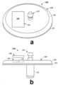
도 1a 및 도 1b는 본 명세서에 제공된 실시형태에 따른 연속 피분석물 모니터링 동안 사용하기 위한 웨어러블 디바이스의 평면 등각도 및 측면도를 각각 예시한다.
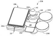
도 1c는 본 명세서에 제공된 실시형태에 따른 연속 피분석물 모니터링 동안 사용하기 위한 웨어러블 디바이스를 구성하는 일부 구성요소를 도시하는 예시적인 실시형태의 분해 등각도를 예시한다.
도 1d는 본 명세서에 제공된 실시형태에 따라서 전자 유닛이 결합되지 않은 웨어러블 디바이스의 베이스 유닛의 등각도를 예시한다.
도 1e는 본 명세서에 제공된 실시형태에 따른 도 1c의 베이스 유닛의 베이스 구조의 확대 등각도를 예시한다.
도 1f는 본 명세서에 제공된 실시형태에 따라서 전자 유닛이 베이스 구조 위에 위치된 도 1c의 베이스 유닛의 베이스 구조 및 전자 유닛의 부분적으로 분해된 확대 등각도를 예시한다.
도 1g는 본 명세서에 제공된 실시형태에 따라서 전자 유닛이 베이스 유닛의 베이스 구조 내에 위치된, 베이스 유닛 및 전자 유닛의 다른 실시형태의 평면 등각도를 예시한다.
도 1h는 본 명세서에 제공된 실시형태에 따른 베이스 구조 및 전자 유닛의 대안적인 실시형태의 분해도를 예시한다.
도 2는 본 명세서에 제공된 실시형태에 따른 연속 피분석물 모니터링 동안 사용하기 위한 웨어러블 디바이스의 전자 유닛의 분해도를 예시한다.
도 3a는 본 명세서에 제공된 실시형태에 따라서 베이스 유닛으로부터 제거된 전자 유닛을 도시하는 연속 피분석물 모니터링 동안 사용하기 위한 웨어러블 디바이스의 측단면도를 예시한다.
도 3b는 본 명세서에 제공된 실시형태에 따라서 전자 유닛 및 베이스 유닛이 함께 결합된 도 3a의 웨어러블 디바이스의 측단면도를 예시한다.
도 4a는 본 명세서에 제공된 실시형태에 따라서 연속 피분석물 모니터링 동안 사용하기 위해 전자 유닛을 웨어러블 디바이스의 베이스 유닛에 결합하는 데 사용되는 결합 도구, 및 웨어러블 디바이스를 사용자에 부착하는 데 사용되는 삽입기의 평면 등각도를 예시한다.
도 4b는 본 명세서에 제공된 실시형태에 따른 도 4a의 삽입기의 개구의 평면도를 예시한다.
도 5a는 본 명세서에 제공된 실시형태에 따른 연속 피분석물 모니터링 동안 사용하기 위해 전자 유닛을 웨어러블 디바이스의 베이스 유닛에 결합하는 데 사용되는 결합 도구의 활성체의 측면도를 예시한다.
도 5b 내지 도 5d는 본 명세서에 제공된 실시형태에 따른 도 5a의 활성체의 정면도, 평면 등각도, 및 저면 등각도를 각각 예시한다.
도 6a는 본 명세서에 제공된 실시형태에 따라서 연속 피분석물 모니터링 동안 사용하기 위해 전자 유닛을 웨어러블 디바이스의 베이스 유닛에 결합하는 데 사용되는 결합 도구의 캐리어의 평면 등각도를 예시한다.
도 6b 내지 도 6d는 본 명세서에 제공된 실시형태에 따른 도 6a의 캐리어의 정면도, 저면 등각도 및 측면도를 각각 예시한다.
도 7a는 연속 피분석물 모니터링 동안 사용하기 위해 웨어러블 디바이스의 베이스 유닛에 전자 유닛을 결합하는 데 사용되는 결합 도구의 활성체 및 캐리어의 조립체의 저면 등각도를 예시하고, 여기에서 본 명세서에 제공된 실시형태에 따라서 결합 도구는 전자 유닛을 유지하고 활성체는 캐리어에 수용된 것으로 도시된다.
도 7b는 본 명세서에 제공된 실시형태에 따른 도 7a의 캐리어 및 활성체를 포함하는 결합 도구의 평면 등각도를 예시한다.
도 7c는 본 명세서에 제공된 실시형태에 따라서 캐리어에 활성체가 수용되지만 전자 유닛이 결합 도구에 의해 유지되지 않는 도 7a의 캐리어의 평면 등각도를 예시한다.
도 8a는 연속 피분석물 모니터링 동안 사용하기 위한 웨어러블 디바이스를 위한 삽입기 및 전자 유닛을 웨어러블 디바이스의 베이스 유닛에 결합하도록 구성된 결합 도구의 분해 등각도를 예시하고, 여기에서 결합 도구 및 전자 유닛은 본 명세서에 제공된 실시형태에 따라서 삽입기에 수용된다.
도 8b는 연속 피분석물 모니터링 동안 사용되는 웨어러블 디바이스를 위한 삽입기, 및 전자 유닛을 웨어러블 디바이스의 베이스 유닛에 결합하도록 구성된 결합 도구의 분해 등각도를 예시하고, 여기에서 본 명세서에 제공된 실시형태에 따라서 전자 유닛은 베이스 유닛에 수용되고 결합 도구는 후퇴된다.
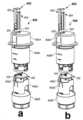
도 9a는 잠금 구성에 있는 커플링 도구를 포함하는 도 8a의 삽입기의 측단면도를 예시하고, 여기에서 전자 유닛은 본 명세서에 제공된 실시형태에 따라서 결합 도구에 의해 유지된다.
도 9b는 본 명세서에 제공된 실시형태에 따라서 결합 도구가 잠금 해제 구성에 있고 전자 유닛 및 베이스 유닛이 함께 결합된 도 9a의 삽입기의 측단면도를 예시한다.
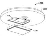
도 10은 본 명세서에 제공된 실시형태에 따라서 전자 유닛과 베이스 유닛 사이의 관계를 도시하는 연속 피분석물 모니터링에서 사용하기 위한 웨어러블 디바이스의 다른 예의 저면 등각도를 예시한다.
도 11은 본 명세서에 제공된 실시형태에 따라서 연속 피분석물 모니터링 디바이스에서 사용하기 위해 전자 유닛을 웨어러블 디바이스의 베이스 유닛에 결합하는 예시적인 방법의 흐름도를 예시한다.1A and 1B illustrate top isometric and side views, respectively, of a wearable device for use during continuous analyte monitoring in accordance with embodiments provided herein.
1C illustrates an exploded isometric view of an example embodiment showing some components that make up a wearable device for use during continuous analyte monitoring in accordance with embodiments provided herein.
1D illustrates an isometric view of a base unit of a wearable device without coupled electronic units, in accordance with embodiments provided herein.
1E illustrates an enlarged isometric view of the base structure of the base unit of FIG. 1C in accordance with embodiments provided herein.
1F illustrates a partially exploded, enlarged isometric isometric view of the base structure and electronic unit of the base unit of FIG. 1C with the electronic unit positioned above the base structure, in accordance with embodiments provided herein.
1G illustrates a top isometric view of another embodiment of a base unit and an electronic unit, with the electronic unit positioned within a base structure of the base unit, in accordance with embodiments provided herein.
1H illustrates an exploded view of an alternative embodiment of a base structure and electronic unit in accordance with embodiments provided herein.
2 illustrates an exploded view of an electronic unit of a wearable device for use during continuous analyte monitoring in accordance with embodiments provided herein.
3A illustrates a cross-sectional side view of a wearable device for use during continuous analyte monitoring showing the electronic unit removed from the base unit in accordance with embodiments provided herein.
3B illustrates a cross-sectional side view of the wearable device of FIG. 3A with an electronic unit and a base unit coupled together in accordance with embodiments provided herein.
4A shows a coupling tool used to couple the electronic unit to the base unit of a wearable device for use during continuous analyte monitoring, and an inserter used to attach the wearable device to a user, in accordance with embodiments provided herein. Illustrates the flat isometric view of
4B illustrates a top view of an opening of the inserter of FIG. 4A according to an embodiment provided herein.
5A illustrates a side view of an activator of a coupling tool used to couple an electronic unit to a base unit of a wearable device for use during continuous analyte monitoring in accordance with embodiments provided herein.
5B-5D illustrate front, top isometric, and bottom isometric views, respectively, of the active body of FIG. 5A in accordance with embodiments provided herein.
6A illustrates a top isometric view of a carrier of a coupling tool used to couple an electronic unit to a base unit of a wearable device for use during continuous analyte monitoring in accordance with embodiments provided herein.
6B-6D illustrate front, bottom isometric and side views, respectively, of the carrier of FIG. 6A in accordance with embodiments provided herein.
7A illustrates a bottom isometric view of an assembly of an activator and a carrier of a coupling tool used to couple an electronic unit to a base unit of a wearable device for use during continuous analyte monitoring, wherein implementations provided herein Depending on the form, the coupling tool holds the electronic unit and the activator is shown housed in the carrier.
FIG. 7B illustrates a top isometric view of a coupling tool comprising the carrier and activator of FIG. 7A in accordance with embodiments provided herein.
FIG. 7C illustrates a top isometric view of the carrier of FIG. 7A in which the actives are received in the carrier but the electronic units are not retained by the coupling tool, in accordance with embodiments provided herein.
8A illustrates an exploded isometric view of a coupling tool configured to couple an inserter and electronic unit for a wearable device for use during continuous analyte monitoring to a base unit of the wearable device, wherein the coupling tool and electronic unit are Accommodated in an inserter according to embodiments provided herein.
8B illustrates an exploded isometric view of an inserter for a wearable device used during continuous analyte monitoring, and a coupling tool configured to couple an electronic unit to a base unit of the wearable device, wherein embodiments provided herein are useful. Thus, the electronic unit is accommodated in the base unit and the engagement tool is retracted.
FIG. 9A illustrates a cross-sectional side view of the inserter of FIG. 8A including the coupling tool in a locking configuration, where the electronic unit is retained by the coupling tool in accordance with embodiments provided herein.
FIG. 9B illustrates a cross-sectional side view of the inserter of FIG. 9A with the coupling tool in an unlocked configuration and the electronic unit and base unit coupled together in accordance with embodiments provided herein.
10 illustrates a bottom isometric view of another example of a wearable device for use in continuous analyte monitoring showing the relationship between an electronic unit and a base unit in accordance with embodiments provided herein.
11 illustrates a flow diagram of an exemplary method of coupling an electronic unit to a base unit of a wearable device for use in a continuous analyte monitoring device in accordance with embodiments provided herein.
사람의 피분석물 수준(예를 들어, 포도당 농도)을 보다 면밀히 모니터링하고 피분석물 수준에서의 변화를 검출하기 위해, 연속 피분석물 모니터링(예를 들어, 연속 포도당 모니터링(CGM))을 위한 방법 및 장치가 개발되었다. CGM 시스템이 동작 동안 연속적인 전기화학 신호와 같은 포도당 신호를 "연속적으로" 생성하지만, 생성된 포도당 신호의 측정은 전형적으로 진정으로 연속적이지 않고 몇 분마다 수행된다. 아래의 설명이 연속 포도당 모니터링에 관한 것이지만, 아래에 설명된 장치 및 방법은 예를 들어 콜레스테롤, 젖산염, 요산, 알코올 등과 같은 다른 연속 피분석물 모니터링 시스템에서 다른 피분석물의 모니터링에 쉽게 적응될 수 있다.for continuous analyte monitoring (eg, continuous glucose monitoring (CGM)), to more closely monitor analyte levels (eg, glucose concentration) in humans and to detect changes in analyte levels; Methods and devices have been developed. Although CGM systems "continuously" generate a glucose signal, such as a continuous electrochemical signal, during operation, measurements of the glucose signal generated are typically not truly continuous and are performed every few minutes. Although the description below relates to continuous glucose monitoring, the devices and methods described below are readily adaptable to the monitoring of other analytes in other continuous analyte monitoring systems, such as, for example, cholesterol, lactate, uric acid, alcohol, and the like. .
CGM 시스템은 일반적으로 핸드헬드 모니터 또는 휴대폰, 컴퓨터 또는 서버와 같은 다른 휴대용 디바이스와 같은 외부 디바이스와 무선으로 통신하는 웨어러블 부분("웨어러블 디바이스")을 갖는다. 웨어러블 디바이스는 제거되어 교체되기 전에 며칠 또는 심지어 몇 주(예를 들어, 1 내지 2주) 동안 착용될 수 있다. 웨어러블 디바이스는 피하로 삽입(이식)되는 바이오센서를 포함한다. 웨어러블 디바이스는 또한 바이오센서를 바이어싱하고 이식된 바이오센서의 구성요소와의 전기화학 반응에 의해 생성된 전류 신호를 측정하도록 구성된, 바이오센서에 결합된 회로망(circuitry)을 포함할 수 있다. 웨어러블 디바이스는 또한 측정된 전류 신호에 기초하여 피분석물(예를 들어, 포도당) 수준을 결정하기 위한 처리 회로망뿐만 아니라 피분석물(예를 들어, 포도당) 수준을 외부 디바이스에 통신하기 위한 전자 송신기 회로망을 포함할 수 있다. 웨어러블 디바이스는 복부, 상완의 후면 또는 다른 적절한 위치와 같은 피부의 외부 표면에 부착(예를 들어, 접착)될 수 있다. CGM 시스템은 간질액 또는 간접적인 모세혈관의 샘플에서 피분석물(예를 들어, 포도당) 농도 또는 피분석물 수준을 측정한다.A CGM system typically has a wearable portion ("wearable device") that communicates wirelessly with an external device, such as a handheld monitor or other portable device such as a cell phone, computer, or server. The wearable device may be worn for days or even weeks (eg, 1-2 weeks) before being removed and replaced. The wearable device includes a biosensor that is inserted (implanted) subcutaneously. The wearable device may also include circuitry coupled to the biosensor configured to bias the biosensor and measure a current signal generated by an electrochemical reaction with a component of the implanted biosensor. The wearable device may also include processing circuitry for determining an analyte (eg, glucose) level based on the measured current signal, as well as an electronic transmitter for communicating the analyte (eg, glucose) level to an external device. may contain networks. The wearable device may be attached (eg, glued) to an external surface of the skin, such as on the abdomen, the back of the upper arm, or other suitable location. CGM systems measure analyte (eg, glucose) concentration or analyte levels in interstitial fluid or indirect capillary samples.
CGM 시스템은 핑거 스틱과 같은 혈액 샘플의 흡인에 의해 수반될 각각의 이러한 측정에 대한 필요 없이 사용자의 피분석물(예를 들어, 포도당) 수준의 빈번한 측정을 제공할 수 있다. CGM 시스템은 CGM 시스템의 교정을 확인하기 위해 때때로 핑거 스틱을 사용하고, 스위스 바젤에 소재한 Ascensia Diabetes Care AG의 Contour NEXT One®과 같은 혈당 측정(BGM) 시스템을 사용할 수 있다.The CGM system can provide frequent measurements of the user's analyte (eg, glucose) level without the need for each such measurement to be accompanied by aspiration of a blood sample, such as with a finger stick. The CGM system may use a blood glucose monitoring (BGM) system such as the Contour NEXT One® from Ascensia Diabetes Care AG, Basel, Switzerland, sometimes using a finger stick to check the calibration of the CGM system.
전술한 바와 같이, CGM 시스템의 웨어러블 디바이스는 일반적으로 일정 기간 동안 착용되고, 이어서 제거되고 새로운 웨어러블 디바이스로 교체된다. 설계된 간격 후에 CGM 시스템의 웨어러블 디바이스를 교체해야 하는 것은 이러한 연속 피분석물 모니터링을 수행하는 비용을 크게 증가시킬 수 있다.As mentioned above, the wearable device of the CGM system is generally worn for a period of time, then removed and replaced with a new wearable device. Having to replace the CGM system's wearable device after designed intervals can significantly increase the cost of performing such continuous analyte monitoring.
본 명세서에 설명된 실시형태에서, 웨어러블 디바이스는 베이스 유닛(예를 들어, 일회용 부분) 및 전자 유닛(예를 들어, 재사용 가능 부분)을 포함할 수 있다. 일부 실시형태에서, 베이스 유닛은 웨어러블 디바이스를 위한 전원, 피분석물 센서(바이오센서), 및/또는 기타 전자 구성요소를 포함할 수 있다. 전자 유닛은 예를 들어 피분석물 센서에 바이어스 전압을 제공하고 피분석물 센서를 통해 전류 신호를 측정하는 데 사용되는 전자 회로망을 포함할 수 있으며, 또한 측정된 전류 신호에 기초하여 포도당 농도값과 같은 피분석물 농도값을 계산하고 그리고/또는 피분석물 농도값 정보를 외부 디바이스로 전송할 수 있다.In the embodiments described herein, a wearable device may include a base unit (eg, a disposable portion) and an electronic unit (eg, a reusable portion). In some embodiments, a base unit may include a power source for a wearable device, an analyte sensor (biosensor), and/or other electronic components. The electronic unit may include, for example, electronic circuitry used to provide a bias voltage to the analyte sensor and measure a current signal through the analyte sensor, and may also determine a glucose concentration value and a value based on the measured current signal. The same analyte concentration value may be calculated and/or analyte concentration value information may be transmitted to an external device.
일부 실시형태에서, 전자 유닛은 웨어러블 디바이스를 위한 전원 장치를 포함할 수 있다. 전자 유닛 내의 예시적인 회로망은 또한 연산 증폭기, 전류 감지 회로망 등과 같이 피분석물 센서를 바이어싱하고 피분석물 센서를 통과하는 전류를 감지하기 위한 아날로그 프런트 엔드를 포함할 수 있다. 전자 유닛 내의 다른 회로망은 전류 신호를 디지털화하기 위한 아날로그-디지털 컨버터(ADC)와 같은 처리 회로망, 디지털화된 전류 신호를 저장하는 메모리, 측정된 전류 신호에 기초하여 포도당 농도값을 계산하기 위한 마이크로프로세서 및 마이크로제어기 등과 같은 제어기, 및 포도당 농도값을 외부 디바이스로 송신 및/또는 외부 디바이스로부터 명령을 수신하기 위한 송신기/수신기 회로망을 포함할 수 있다.In some embodiments, the electronic unit may include a power supply for a wearable device. Exemplary circuitry within the electronic unit may also include an analog front end for biasing the analyte sensor and sensing the current passing through the analyte sensor, such as an operational amplifier, current sensing circuitry, or the like. Other circuitry within the electronic unit includes processing circuitry such as an analog-to-digital converter (ADC) to digitize the current signal, a memory to store the digitized current signal, a microprocessor to calculate a glucose concentration value based on the measured current signal, and A controller, such as a microcontroller, and transmitter/receiver circuitry for transmitting glucose concentration values to an external device and/or receiving commands from the external device.
전자 유닛은 일반적으로 웨어러블 디바이스에서 가장 비싼 부분이며, 웨어러블 디바이스가 이용되는 기간보다 상당히 오래 지속될 수 있다. 예를 들어, 웨어러블 디바이스는 일반적으로 약 2주 후에 폐기되는 반면에, 전자 유닛은 10, 20, 50, 100개 또는 그 이상의 베이스 유닛과 함께 재사용될 수 있다.The electronic unit is typically the most expensive part of a wearable device and can last considerably longer than the wearable device is in use. For example, wearable devices are generally discarded after about two weeks, whereas electronic units can be reused with 10, 20, 50, 100 or more base units.
웨어러블 디바이스는 사용자의 움직임을 방해하거나 사용자를 짜증나게 하지 않도록 매우 작을 수 있다. 따라서, 전자 유닛은 작을 수 있고, 이는 전자 유닛과 베이스 유닛을 함께 수동으로 결합하는 것을 어렵게 만들 수 있다. 이와 같이, 재사용 가능한 전자 유닛을 베이스 유닛에 결합하는 결합 도구 및 방법이 제공된다. 이들 및 다른 실시형태는 도 1a 내지 도 11을 참조하여 아래에서 설명된다.The wearable device may be very small so as not to impede the user's movement or annoy the user. Thus, the electronic unit can be small, which can make it difficult to manually couple the electronic unit and base unit together. Thus, a coupling tool and method for coupling a reusable electronic unit to a base unit is provided. These and other embodiments are described below with reference to FIGS. 1A-11 .
이제 연속 피분석물 모니터링 동안 사용하기 위한 웨어러블 디바이스(100) 및 그 구성요소의 다양한 도면을 예시하는 도 1a 내지 도 1h를 참조한다. 도 1a 및 도 1b는 본 명세서에 제공된 실시형태에 따른 웨어러블 디바이스(100)를 예시한다. 도 1c는 웨어러블 디바이스(100) 내에 위치된 구성요소의 예시적인 실시형태의 분해 등각도를 예시한다. 도 1d는 내부에 전자 유닛이 위치되지 않는 웨어러블 디바이스(100)의 베이스 유닛(102)의 등각도를 예시한다. 도 1c의 구성요소는 예를 들어 구성요소를 유지하기 위해 오버몰딩될 수 있는 도 1d의 베이스 유닛(102) 내에 위치될 수 있다. 도 1e 내지 도 1h는 베이스 유닛(102)에 포함된 베이스 구조의 예의 다양한 등각도를 예시한다.Reference is now made to FIGS. 1A-1H , which illustrate various views of a
웨어러블 디바이스(100)는 웨어러블 디바이스(100)를 형성하기 위해 서로 인터페이싱하고 결합되는 베이스 유닛(102)(예를 들어, 일회용 베이스 유닛) 및 전자 유닛(104)(예를 들어, 재사용 가능한 전자 유닛)을 포함할 수 있다. 전자 유닛(104)은 때때로 송신기 유닛으로서 지칭된다. 베이스 유닛(102)은 캐비티 또는 개구(106) 또는 전자 유닛(104)을 수용하는 다른 결합 구조를 포함할 수 있다. 사용자가 전자 유닛(104)을 베이스 유닛(102)에 결합하는 것을 가능하게 하는 장치 및 방법이 본 명세서에 개시된다. 일부 실시형태에서, 베이스 유닛(102)은 단일 피분석물 모니터링 기간(예를 들어, 7일, 10일, 14일 또는 일부 다른 기간) 후에 폐기되도록 구성되는 반면에, 전자 유닛(104)은 단일 피분석물 모니터링 기간 후에 베이스 유닛(102)으로부터 제거되어 다른 베이스 유닛과 함께 재사용되도록 구성된다. 예를 들어, 전자 유닛(104)은 2, 5, 10, 50, 100개 이상의 새로운 베이스 유닛과 함께 재사용될 수 있다.The
일부 실시형태에서, 베이스 유닛(102)은 밀봉된다. 예를 들어, 캡슐화 층(108)은 베이스 유닛(102) 내의 구성요소 위에 형성될 수 있다. 일부 실시형태에서, 캡슐화 층(108)은 전자 유닛(104)이 베이스 유닛(102)에 결합되는 것을 허용하는 개구(106)를 포함할 수 있다. 일부 실시형태에서, 캡슐화 층(108)은 베이스 유닛(102) 및 그 내부 구성요소 주위에 방수 밀봉을 생성한다. 커넥터(110)는 개구(106)와 같이 노출된 상태로 남아 있을 수 있어서, 전자 유닛(104) 상의 커넥터는 커넥터(110)와의 전기적 연결을 만들 수 있다. 캡슐화 층(108)은 단일 층 또는 다중 층으로 형성될 수 있다. 예를 들어, 캡슐화 층(108)은 액체 실리콘 고무(LSR), 열가소성 엘라스토머(TPE) 등의 하나 이상의 층으로 형성될 수 있다. 다른 적절한 밀봉 재료가 사용될 수 있다.In some embodiments,
베이스 유닛(102)은, 커넥터(110)에 전기적으로 결합되고 간질액과의 접촉 및 반응에 응답하여 전기 신호를 생성하도록 동작 가능한 피분석물 센서(114)(도 1c)를 포함할 수 있다. 전기 신호는 전자 유닛(104)으로 전송될 수 있으며, 여기에서 전기 신호가 측정된다. 전자 유닛(104) 또는 외부 디바이스(도시되지 않음)는 측정된 전기 신호에 적어도 부분적으로 기초하여 포도당 농도(또는 다른 피분석물의 농도)를 결정할 수 있다.The
도 1c 및 도 1e 내지 도 1h는 전자 유닛(104)을 포함하여 웨어러블 디바이스(100)의 베이스 유닛(102) 내에 위치될 수 있는 일부 구성요소의 예시적인 실시형태의 분해도 및 다른 등각도를 예시한다. 도시된 바와 같이, 베이스 유닛(102)은 베이스 유닛(102) 내에서 구성요소를 유지하는 섀시 등일 수 있는 베이스 구조(116)를 포함한다. 베이스 구조(116)의 일부 실시형태는 하나 이상의 전원 지지 위치(118A 내지 118B), 전자 유닛 지지 위치(120) 및 센서 조립체 지지 위치(122)를 가질 수 있다. 일부 실시형태에서, 베이스 구조(116)는 아크릴로나이트릴 부타다이엔 스티렌(ABS), 폴리카보네이트, 나일론, 아세탈, 폴리프탈아마이드(PPA), 폴리설폰, 폴리에터설폰, 폴리에터에터케톤(PEEK), 폴리프로필렌, 고밀도 폴리에틸렌(HDPE) 및 저밀도 폴리에틸렌(LDPE)과 같지만 이에 제한되지 않는 플라스틱으로 형성될 수 있다. 다른 적절한 재료가 사용될 수 있다.1C and 1E-1H illustrate exploded and other isometric views of an exemplary embodiment of some components that may be located within
전원 지지 위치(118A, 118B)는 전자 유닛(104)과 같은 웨어러블 디바이스(100)의 구성요소에 전력을 공급하는 데 사용되는 하나 이상의 전원(124A, 124B)을 지지하기 위한 위치를 제공한다. 예를 들어, 하나 이상의 전원(124A, 124B)은 전원 지지 위치(118A, 118B)에 위치될 수 있다. 일부 실시형태에서, 하나 이상의 전원(124A, 124B)은 배터리, 저장 커패시터, 태양 전지, 발전기 등일 수 있다. 전원(124A, 124B)이 2개의 배터리인 것으로 도시되어 있지만, 더 적거나 더 많은 그리고/또는 상이한 전원이 사용될 수 있다는 것을 이해할 것이다. 전원 지지 위치(118A, 118B)는 하나 이상의 전원(124A, 124B)을 수용하기 위한 임의의 적합한 형상(예를 들어, 직사각형, 정사각형, 원형 등)일 수 있다. 일부 실시형태에서, 전원(124A, 124B)은 전자 유닛(104) 내에 위치될 수 있다.Power
전자 유닛 지지 위치(120)는 베이스 유닛(102)에 결합되거나 그렇지 않으면 부착된 전자 유닛(104)을 유지하도록 구성된다. 일부 실시형태에서, 전자 유닛 지지 위치(120)는 하나 이상의 제1 보유 특징부(126)를 포함할 수 있다. 일부 실시형태에서, 전자 유닛 지지 위치(120)는 4개의 제1 보유 특징부(126)를 포함할 수 있으며, 이는 개별적으로 제1 보유 특징부(126A-126D)로서 지칭된다. 제1 보유 특징부(126)는 예를 들어 도 1g에 도시된 바와 같이, 전자 유닛(104)을 베이스 유닛(102)의 베이스 구조(116)에 결합하고 유지하기 위해 전자 유닛(104) 상의 제2 보유 특징부(128A-128D)로서 개별적으로 지칭되는 제2 보유 특징부(128)와 인터페이싱하고 그리고/또는 이에 대해 가압할 수 있다. 더 적고, 더 많고 그리고/또는 상이한 보유 특징부가 전자 유닛(104)을 베이스 구조(116)에 고정하기 위해 사용될 수 있다. 제1 보유 특징부(126)는 예를 들어 전자 유닛(104)에 있는 제2 보유 특징부(128)의 개구와 맞물리는 돌출부를 포함할 수 있다. 일부 실시형태에서, 제1 및 제2 보유 특징부(126, 128)는 자석, 벨크로, 접착제가 있는 표면 등을 포함할 수 있다.The electronic
일부 실시형태에서, 전자 유닛 지지 위치(120)는 전자 유닛(104)이 베이스 유닛(102) 및/또는 베이스 구조(116)으로부터 제거될 때 제1 보유 특징부(126)가 전자 유닛(104)을 분리 및/또는 해제하도록 베이스 구조(116)가 구부러지고 그리고/또는 파단되는 것을 허용하는 채널, 그루브, 스크라이브 라인 등과 같은 파단 위치(131)(도 1c, 도 1f 및 도 1g)를 포함할 수 있다. 다른 해제 및/또는 파단 위치r가 사용할 수 있다. 일부 실시형태에서, 다른 보유 특징부가 전자 유닛(104)을 유지하기 위해 사용될 수 있으며, 다른 보유 특징부는 전자 유닛(104)을 제거하기 위해 베이스 구조(116)의 굽힘을 요구하지 않는다.In some embodiments, the electronic
회로 기판, 가요성 회로 기판 등과 같은 기판(130)은 전자 유닛 지지 위치(120) 내에 위치될 수 있고, 전자 유닛(104) 상의 유사한 커넥터(도시되지 않음)에 전기 인터페이스를 제공하는 커넥터(110)를 포함할 수 있다. 예를 들어, 커넥터(110)는 전자 유닛(104)이 전자 유닛 지지 위치(120) 내에 위치될 때 전원(124A, 124B)이 전자 유닛(104)에 전력을 제공하는 것을 가능하게 하도록 도체(도시되지 않음)에 의해 전원(124A, 124B)에 전기적으로 연결될 수 있다. 커넥터(110)는 또한 피분석물 센서(114)에 전압을 제공하기 위해 피분석물 센서(114)에 전기적으로 연결될 수 있다.A
도 1h는 베이스 구조(116A) 내에 전자 유닛(104)을 유지하는 제1 및 제2 보유 특징부(132, 134)의 다른 예를 갖는 도 1c의 베이스 구조(116A) 및 전자 유닛(104)의 또 다른 대안적인 실시형태의 분해 등각도를 예시한다. 도 1h의 실시형태에서, 전자 유닛(104)은 제1 보유 특징부(132)를 갖고, 베이스 구조(116A)는 제2 보유 특징부(134)를 갖는다. 전자 유닛(104) 상의 제1 보유 특징부(132)는 제1 보유 특징부(132)를 수용하도록 구성된 개구인 베이스 구조(116A) 상의 제2 보유 특징부(134) 내로 연장될 수 있다.1H is a diagram of the
센서 조립체 지지 위치(122)는 예를 들어 삽입 디바이스(140) 및 삽입 디바이스 캡(142)을 포함할 수 있는 피분석물 센서 조립체(139)의 적어도 일부를 위한 실장 위치를 제공한다. 삽입 디바이스(140)는 본 명세서에 설명된 바와 같이 피분석물 센서(114)를 사용자의 피하 영역으로 도입하기 위해 피부를 관통하는 예리한 단부(146)(도 1c)를 포함하는 삽입 부분(144)을 포함할 수 있다. 삽입 부분(144)은 또한 삽입 샤프트, 바늘, 투관침, 샤프 등으로서 지칭될 수 있다.Sensor
삽입 디바이스(140)의 삽입 부분(144)은 예를 들어 스테인리스강과 같은 금속 또는 플라스틱과 같은 비금속으로 만들어질 수 있다. 다른 재료가 사용될 수 있다. 일부 실시형태에서, 삽입 디바이스(140)의 삽입 부분(144)은 원형 C-채널 튜브, 원형 U-채널 튜브, 정사각형 U-프로파일로 접힌 스탬핑된 시트 금속 부품, U-채널 프로파일이 있는 성형/주조, 레이저 절단 또는 기계 가공 금속 부품, 또는 에칭 또는 그라인딩된 정사각형 U-채널이 있는 단단한 금속 원통일 수 있지만 이에 제한되지 않는다. 다른 삽입 부분 형상이 사용될 수 있다. 삽입 부분(144)에 형성된 채널은 삽입 동안 피분석물 센서(114)를 운반한다. 일부 실시형태에서, 삽입 디바이스(140)의 부분은 예를 들어 ABS, 폴리카보네이트, 나일론, 아세탈, PPA, 폴리설폰, 폴리에터설폰, PEEK, 폴리프로필렌, HDPE, LDPE 등과 같지만 이에 재한되지 않는 플라스틱으로 형성될 수 있다. 다른 재료가 사용될 수 있다.The
삽입 부분(144)은 예를 들어 베이스 구조(116, 116A)의 센서 조립체 지지 위치(122)에 있는 센서 개구(150)(도 1f)를 통해 연장될 수 있다. 피분석물 센서(114)는 전자 유닛 지지 위치(120) 내에서 기판(130)의 커넥터(110)에 전기적으로 연결된다. 커넥터(110)는 피분석물 센서(114)를 전자 유닛 지지 위치(120) 내에 위치된 전자 유닛(104)에 전기적으로 연결한다.
본 명세서에 설명된 제1 및 제2 보유 특징부(126, 128, 132, 134)는 연속 피분석물 모니터링 동안 전자 유닛(104)을 베이스 유닛(102)의 베이스 구조(116, 116A)에 고정(예를 들어, 결합)하는 동시에, 전자 유닛(104)이 연속 피분석물 모니터링 기간 후에 제거되어 재사용되는 것을 가능하게 한다. 베이스 유닛(102)은 단일 피분석물 모니터링 기간 후에 폐기되도록 구성될 수 있는 반면에, 전자 유닛(104)은 단일 피분석물 모니터링 기간 후에 베이스 유닛(102)으로부터 분리되어 다른 베이스 유닛과 함께 재사용되도록 구성될 수 있다. 예를 들어, 베이스 구조(116)는 파단 위치(131)를 따라 구부러질 수 있으며, 이는 전자 유닛(104)으로부터 제1 보유 특징부(126)(도 1f)를 해제한다. 일부 실시형태에서, 단일 피분석물 모니터링 기간은 적어도 7일 내지 10일(예를 들어 최대 14일 이상)일 수 있다. 전자 유닛(104)은 베이스 유닛(102)으로부터 제거되어 (예를 들어, 매번 새로운 피분석물 센서(114)를 포함하는 새로운 베이스 유닛(102)과 함께 5, 10, 20, 50, 100회 이상) 재사용될 수 있다.The first and second retention features 126, 128, 132, 134 described herein secure the
도 2는 본 명세서에 제공된 일부 실시형태에 따른 전자 유닛(104)의 예의 분해도를 예시한다. 도 2의 실시형태에서, 전자 유닛(104)은, 기판(202) 및 그 위의 임의의 구성요소(208)를 덮고 밀봉하기 위해, 상부 커버(204)에 결합되고 하부 커버(206)(예를 들어, 오버몰드 부분)에 의해 덮일 수 있는 기판(202)을 포함할 수 있다. 기판(202)은 회로 기판, 가요성 회로 기판, 또는 전자 유닛(104) 내에서 사용되는 전자 회로망을 위한 다른 실장 위치일 수 있다. 상부 커버(204) 및/또는 하부 커버(206)는 하나 이상의 액체 실리콘 고무(LSR), 열가소성 엘라스토머(TPE), 성형 플라스틱 커버 등의 하나 이상의 층으로 형성될 수 있다. ABS, 폴리카보네이트, 나일론, 아세탈, PPA, 폴리설폰, 폴리에터설폰, PEEK, 폴리프로필렌, HDPE, LDPE 등과 같지만 이에 제한되지 않는 다른 재료가 사용될 수 있다.2 illustrates an exploded view of an example of an
기판(202)은 전자 유닛(104)이 베이스 구조(116)의 전자 유닛 지지 위치(120) 내에 위치될 때 베이스 유닛(102)의 커넥터(110)(도 1c)와 인터페이싱하도록 구성된 인터페이스(212)(예를 들어, 커넥터)를 포함할 수 있다. 하부 커버(206)에 있는 개구(214)는 예를 들어 인터페이스(212)가 베이스 유닛(102)의 커넥터(110)와 결합되는 것을 가능하게 하도록 제공될 수 있다. 일부 실시형태에서, 구성요소(208) 중 하나 이상은 인터페이스(212) 및 베이스 유닛(102)의 커넥터(110)를 통해 피분석물 센서(114)에 전기적으로 결합될 수 있다.The
일부 실시형태에서, 전자 유닛(104)이 베이스 유닛(102) 내에 위치될 때, 전자 유닛(104)과 베이스 유닛(102)이 밀봉된 유닛을 형성하도록, 하부 커버(206)는 베이스 유닛(102)의 개구(106)의 측벽 또는 다른 부분에 대해 밀봉하도록 구성된 입술부 또는 유사한 특징부와 같은 밀봉 부재(216)를 포함할 수 있다(또한 도 3a 및 도 3a 참조). 일부 실시형태에서, 상부 커버(204)는 전자 유닛 지지 위치(120)(예를 들어, 하나 이상의 제1 보유 특징부(126)) 내에서 제1 보유 특징부(126A-126D)(도 1c)와 인터페이싱하도록 구성된 하나 이상의 제2 보유 특징부(128)를 포함할 수 있다. 이러한 제1 및 제2 보유 특징부는 전자 유닛(104)을 베이스 유닛(102)에 단단히 유지하고 사용 동안 커넥터(110)를 인터페이스(212)와 접촉시켜 유지하도록 인터페이싱할 수 있다. 다른 실시형태에서, 상부 커버(204)는 밀봉 부재를 포함할 수 있고, 그리고/또는 하부 커버(206)는 보유 특징부를 포함할 수 있다.In some embodiments, when the
도 3a는 일부 실시형태에 따라서 베이스 유닛(102)으로부터 전자 유닛(104)이 제거된 웨어러블 디바이스(100)의 단면도를 예시한다. 도 3b는 일부 실시형태에 따라서 전자 유닛(104) 및 베이스 유닛(102)이 함께 결합된 도 3a의 웨어러블 디바이스(100)의 단면도를 예시한다. 본 명세서에 설명된 바와 같이, 전자 유닛(104) 및 베이스 유닛(102)은 전자 유닛(104)의 인터페이스(212) 및 베이스 유닛(102)의 커넥터(110)만이 노출되는 밀봉된 유닛(예를 들어, 방수)일 수 있다. 커넥터(110) 및 인터페이스(212)는 또한 전자 유닛(104)이 베이스 유닛(102)과 결합될 때 어떠한 외부 환경으로부터도 밀봉될 수 있다.3A illustrates a cross-sectional view of
이제 전자 유닛(104)(도 1b)을 웨어러블 디바이스(100)(도 1b)의 베이스 유닛(102)에 결합하는 데 사용될 수 있는 결합 도구(400)의 측면 등각도를 예시하는 도 4a를 참조한다. 결합 도구(400)는 다른 유형의 웨어러블 디바이스의 다른 전자 유닛 및 베이스 유닛을 함께 결합하는 데 사용될 수 있다. 결합 도구(400)는 활성체(402) 및 캐리어(404)를 포함하고 이들로 만들어진다. 결합 도구(400)는 사용자가 본 명세서에 설명된 바와 같은 웨어러블 디바이스(100)를 사용자에 부착하는 것을 가능하게 하는 삽입기(406)와 함께 사용될 수 있다. 요약하면, 전자 유닛(104)이 결합되지 않은 베이스 유닛(102)은 삽입기(406) 내에 유지될 수 있다(도 8a 참조). 전자 유닛(104)은 캐리어(404)에 의해 보유되어 유지되고, 캐리어(404) 및 전자 유닛(104)은 삽입기(406) 내에 캐리어(404) 및 전자 유닛(104)을 위치시키기 위해 삽입기(406)의 상부에 있는 개구(422)에 삽입된다(도 9a 참조). 이어서, 활성체(402)는 캐리어(404)에 대해(예를 들어, 일부 실시형태에서 그 안에서) 이동되어, 활성체(402)가 캐리어(404)로부터 전자 유닛(104)을 해제하고 전자 유닛(104)을 베이스 유닛(102)에 결합하게 한다(도 9b 참조).Reference is now made to FIG. 4A which illustrates a side isometric view of a
결합 도구(400)는 결합 도구(400)가 전자 유닛(104)을 해제하도록 구성될 때 잠금 해제 구성에 있는 것으로 언급될 수 있다. 결합 도구(400)는 결합 도구(400)가 전자 유닛(104)을 유지하도록 구성될 때 잠금 구성에 있는 것으로 언급될 수 있다.
본 명세서에 제공된 실시형태에 따른 활성체(402)의 다양한 도면을 예시하는 도 5a 내지 도 5d를 추가로 참조한다. 도 5a는 활성체(402)의 측면도를 예시하고, 도 5b는 활성체(402)의 정면도를 예시하고, 도 5c는 활성체(402)의 평면 등각도를 예시하고, 도 5d는 활성체(402)의 저면 등각도를 예시한다. 활성체(402)는 상부 표면(510S)을 갖는 상부 부분(510)을 포함할 수 있다. 상부 표면(510S)은 전자 유닛(104)을 베이스 유닛(102)에 결합하는 동안 사용자에 의해 가압되도록 구성될 수 있다.Reference is further made to FIGS. 5A-5D , which illustrate various views of an
제1 부재(512)는 상부 부분(510)으로부터 단부(512A)까지 길이(L51)만큼 연장될 수 있다. 단부(512A)는 전자 유닛(104) 및 베이스 유닛(102)이 함께 결합됨에 따라서 전자 유닛(104)과 접촉하도록 구성될 수 있다. 예를 들어, 단부(512A)는 전자 유닛(104)의 상부 커버(204)(도 2)와 접촉하도록 구성될 수 있다. 제1 부재(512)는 결합 동안 전자 유닛(104)과 베이스 유닛(102) 사이에 가해지는 힘을 견디도록 충분히 강성일 수 있다. 일부 실시형태에서, 활성체(402)는 단부(512A)가 전자 유닛(104)과 접촉하지 않을 때 잠금 위치 또는 구성에 있고, 단부(512A)가 전자 유닛(104)과 접촉할 때 잠금 해제 위치 또는 구성에 있는 것으로 언급될 수 있다. 잠금 해제 위치에서, 전자 유닛(104)은 더 이상 유지되지 않는다. 길이(L51)는 활성체(402)가 본 명세서에 설명된 바와 같이 잠금 해제 위치에 있을 때 캐리어(404)로부터 전자 유닛(104)을 밀어내도록 충분히 길 수 있다.The
활성체(402)는 또한 상부 부분(510)으로부터 연장되는 접촉 부재(514)를 포함할 수 있다. 접촉 부재(514)는 상부 부분(510)과 접촉 부재(514)의 단부(514A) 사이의 길이(L52)만큼 연장될 수 있다. 본 명세서에서 설명된 바와 같이, 접촉 부재(514)는 활성체(402)가 잠금 해제 구성에 있을 때 또는 캐리어(404)가 본 명세서에 설명된 바와 같이 잠금 구성으로부터 잠금 해제 구성으로 전환할 때 캐리어(404)로부터 전자 유닛(104)을 해제하기 위해 캐리어(404)의 가동성 또는 가요성 부재와 맞물릴 수 있다.
캐리어(404)의 실시형태의 상이한 도면을 예시하는 도 6a 내지 도 6d를 추가로 참조한다. 도 6a는 캐리어(404)의 평면 등각도를 예시하고, 도 6b는 캐리어(404)의 정면도를 예시하고, 도 6c는 캐리어(404)의 저면 등각도를 예시하고, 도 6d는 캐리어(404)의 측면도를 예시한다.Reference is further made to FIGS. 6A-6D , which illustrate different views of an embodiment of
캐리어(404)는 전자 유닛(104)을 베이스 유닛(102) 및/또는 삽입기(406)로 운반하도록 구성될 수 있다. 캐리어(404)는 제1 측면(616A)(예를 들어, 하부측) 및 제2 측면(616B)(예를 들어, 상부측)을 가질 수 있다. 길이(L61)는 제1 측면(616A)과 제2 측면(616B) 사이에서 연장된다. 일부 실시형태에서, 길이(L61)는 활성체(402)의 제1 부재(512)의 길이(L51)(도 5a)보다 약간 짧을 수 있다. 캐리어(404)는 제1 측면(616A)과 제2 측면(616B) 사이에서 연장되는 수용 특징부(618)(예를 들어, 도시된 바와 같이 직사각형 구멍)을 가질 수 있다. 수용 특징부(618)는 활성체(402)의 제1 부재(512)의 적어도 일부를 수용하고 제1 부재(512)가 수용 특징부(618) 내에서 이동(예를 들어, 슬라이딩)하는 것을 가능하게 하도록 형상화 및/또는 크기화될 수 있다. 수용 특징부(618)는 수용 특징부 제1 단부(618A) 및 수용 특징부 제2 단부(618B)를 포함할 수 있고, 전자 유닛(104)은 결합 도구(400)가 잠금 구성에 있을 때, 예를 들어 전자 유닛(104)이 캐리어(404)에 의해 유지될 때(도 7a 및 도 7b 참조) 수용 특징부 제1 단부(618A)에 인접하게 위치되도록 구성된다. 수용 특징부(618)는 작은 구멍으로서 도시되어 있다. 다른 실시형태에서, 수용 특징부(618)는 슬롯, 그루브, 또는 본 명세서에 설명된 기능을 수행하는 다른 특징부일 수 있다.
캐리어(404)는 제1 측면(616A) 또는 제2 측면(616B)으로부터 보았을 때 캐리어(404)의 가로 형상을 한정하는 외부 표면을 가질 수 있다. 캐리어(404)의 가로 형상은 캐리어(404)가 본 명세서에 설명된 바와 같이 삽입기(406)에 있는 개구(422)(도 4b) 내에 수용되는 것을 가능하게 한다. 예를 들어, 캐리어(404)는 캐리어(404)가 개구(422) 내에서 슬라이딩하는 것을 허용하도록 구성된 형상을 포함할 수 있다. 일부 실시형태에서, 캐리어(404)의 가로 형상은 개구(422)와 동일할 수 있지만, 캐리어(404)가 개구(422) 내에서 최소 마찰로 이동하는 것을 가능하게 하기 위해 약간 더 작을 수 있다.The
본 명세서에 제공된 실시형태에 따른 개구(422)의 평면도를 예시하는 도 4b를 추가로 참조한다. 캐리어(404)는 개구(422) 내에서 특정 방향으로 캐리어(404)를 배향시키는 하나 이상의 인덱싱 디바이스를 포함할 수 있다. 도 4b 및 도 6a 내지 도 6d의 실시형태에서, 캐리어(404)는, 외부 표면으로부터 연장되고 개구(422) 내에서 캐리어(404)를 배향시키는 2개의 레일, 즉 제1 레일(624A) 및 제2 레일(624B)을 포함한다. 제1 레일(624A) 및 제2 레일(624B)은 각각 개구(422)의 제1 채널(426A) 및 제2 채널(426B) 내에 수용 가능할 수 있다. 제1 레일(624A), 제2 레일(624B), 제1 채널(426A), 및 제2 채널(426B)의 위치는 개구(422) 내에서 오직 하나의 배향으로만 수용되는 캐리어(404)를 제공한다. 예를 들어, 도 4b의 실시형태에서, 개구(422)는 제1 측면(422A) 및 반대쪽 제2 측면(422B)을 포함한다. 제1 채널(426A) 및 제2 채널 모두는 제1 측면(422A)으로부터 길이(L41) 및 제2 측면(422B)으로부터 길이(L42)에 위치될 수 있으며, 길이(L41)는 길이(L42)와 동일하지 않다. 따라서, 제1 채널(426A) 및 제2 채널(426B)의 위치는 캐리어(404)가 개구(422) 내에서 오직 하나의 배향으로만 수용되는 것을 가능하게 한다. 하나의 배향은 전자 유닛(104)과 베이스 유닛(102)의 적절한 결합을 제공한다. 다른 인덱싱 및/또는 배향 메커니즘이 사용될 수 있다.Reference is further made to FIG. 4B which illustrates a top view of an
캐리어(404)는, 전자 유닛(104)을 유지하고 활성체(402)가 내부에 수용된 캐리어(404)의 실시형태의 저면도 및 평면 등각도인 도 7a 및 도 7b에 도시된 바와 같이 전자 유닛(104)을 유지하도록 구성된다. 일부 실시형태에서, 캐리어(404)는 전자 유닛(104)을 수용하도록 구성된(예를 들어, 형상화되고 크기화된) 캐비티(630)(도 6a 내지 도 6c 및 도 7c)를 가질 수 있다. 캐비티(630)는 캐리어(404)의 제1 측면(616A)에 근접하게 위치될 수 있고, 수용 특징부(618)(도 6a)와 교차할 수 있어서, 활성체(402)의 제1 부재(512)의 단부(512A)(도 5a 내지 도 5d)는 전자 유닛(104)과 접촉할 수 있다. 예를 들어, 캐비티(630)는 수용 특징부(618)의 수용 특징부 제1 단부(618A)에 있거나 또는 이와 인접할 수 있다. 활성체(402)의 제1 부재(512)는 도 9b에 도시된 바와 같이 전자 유닛(104)과 베이스 유닛(102)을 함께 강제하기 위해 전자 유닛(104)과 접촉할 수 있다. 일부 실시형태에서, 캐비티(630)는 전자 유닛(104)을 캐리어(404)의 제1 측면(616A)과 동일 높이로 유지하도록 구성된다.The
일부 실시형태에서, 캐리어(404)는 예를 들어 캐비티(630) 내에서 또는 캐리어(404)의 단부에서 전자 유닛(104)을 캐리어(404)에 유지하도록 구성된 하나 이상의 보유 디바이스를 포함할 수 있다. 캐리어(404) 및/또는 하나 이상의 보유 디바이스는 캐리어(404)가 전자 유닛(104)을 유지하거나 유지하도록 구성될 때 잠금 구성 또는 잠금 상태에 있을 수 있다. 캐리어(404) 및/또는 하나 이상의 보유 디바이스는 전자 유닛(104)이 캐리어(404)로부터 해제되거나 캐리어(404)가 전자 유닛(104)을 해제하도록 구성될 때 잠금 해제 구성 또는 잠금 해제 상태에 있을 수 있다. 도 6a 내지 도 7c의 실시형태에서, 캐리어(404)는, 예를 들어 캐비티(630) 내에 전자 유닛(104)을 유지하도록 구성되고 활성체(402)의 접촉 부재(514)(도 4a)가 캐비티(630)로부터 전자 유닛(104)을 해제하는 것을 가능하게 하는 캐리어 보유 디바이스(632)를 포함할 수 있다. 예를 들어, 접촉 부재(514)(도 5a 내지 도 5d 및 도 7a 내지 도 7c)는 캐리어(404)에 대한 활성체(402)의 이동에 응답하여 캐리어 보유 디바이스(632)로부터 전자 유닛(104)을 해제하도록 구성될 수 있다.In some embodiments,
캐리어 보유 디바이스(632)는 전자 유닛(104)을 캐리어(404)에 유지하는 하나 이상의 후크를 포함할 수 있다. 도 6a 내지 도 7c의 실시형태에서, 캐리어 보유 디바이스(632)는 제1 후크(636A)를 갖는 제1 아암(634) 및 제2 후크(636B)를 갖는 제2 아암(635)을 포함할 수 있다. 제1 아암(634)은 제1 지점(638A)을 중심으로 선회하거나 유연할 수 있고, 제2 아암(635)은 제2 지점(638B)을 중심으로 선회하거나 유연할 수 있다. 일부 실시형태에서, 제1 지점(638A) 및 제2 지점(638B)은 제1 아암(634) 및 제2 아암(635)이 캐리어(404)의 본체 부분에 연결되는 위치일 수 있다. 일부 실시형태에서, 제1 아암(634) 및 제2 아암(635)이 전자 유닛(104)을 캐비티(630)로부터 해제하기 위해 본 명세서에 설명된 바와 같이 활성체(402)의 접촉 부재(514)와의 상호작용 또는 맞물림시에 굽어지도록, 제1 아암(634) 및 제2 아암(635)은 유연하다. 제1 아암(634) 및 제2 아암(635)은 캐리어(404)의 본체로부터 갭만큼 분리될 수 있다.The
제1 후크(636A) 및 제2 후크(636B)는 캐리어(404)가 잠금 구성에 있을 때 전자 유닛(104)을 캐리어(404)에 파지 및/또는 유지하도록 구성될 수 있다. 일부 실시형태에서, 제1 후크(636A) 및 제2 후크(636B)는 전자 유닛(104)을 캐비티(630)에 유지하기 위해 전자 유닛(104)의 보유 특징부(예를 들어, 도 2에 도시된 보유 특징부(128A 내지 128D)) 중 2개와 맞물리도록 구성될 수 있다. 도 7a 및 도 7b에 묘사된 실시형태에서, 제1 후크(636A)는 보유 특징부(128C)와 맞물린 것으로 도시되고, 제2 후크(636B)는 보유 특징부(128A)와 맞물린 것으로 도시되며, 이는 전자 유닛(104)을 캐비티(630)에 유지한다.The
제1 아암(634)은 내부 표면(634S)(도 6b)을 가질 수 있고, 제2 아암(635)은 내부 표면(634S)과 마주하는 내부 표면(635S)을 가질 수 있다. 내부 표면(634S) 및 내부 표면(635S)은 제1 아암(634)과 제2 아암(635) 사이에서 활성체(402)의 접촉 부재(514)를 안내할 수 있다. 제1 아암(634)은 또한 내부 표면(634S)의 일부를 포함하는 제1 돌출부(634P)를 가질 수 있다. 제2 아암(635)은 또한 내부 표면(635S)의 일부를 포함하는 제2 돌출부(635P)를 가질 수 있다. 제1 돌출부(634P) 및 제2 돌출부(635P)는 활성체(402)가 잠금 해제 구성으로 전환함에 따라서 접촉 부재(514)와 접촉하도록 구성될 수 있으며, 전환 해제 구성은 캐리어(404)를 잠금 해제 구성으로 전환하고 본 명세서에 설명된 바와 같이 전자 유닛(104)을 해제한다.The
활성체(402)가 잠금 구성에 있을 때, 캐리어(404)는 잠금 구성에 있다. 일부 실시형태에서, 제1 아암(634) 및 제2 아암(635)은 서로를 향해 편향될 수 있어서, 캐리어(404)는 상시 잠금 구성에 있을 수 있다. 일부 실시형태에서, 제1 후크(636A) 및 제2 후크(636B)는 캐리어(404)가 상시 잠금 구성에 있도록 서로를 향해 상시 편향될 수 있다. 활성체(402)의 접촉 부재(514)가 제1 돌출부(634P) 및 제2 돌출부(635P)와 맞물림에 따라서, 제1 후크(636A) 및 제2 후크(636B)는 서로 분리되어, 캐리어(404)를 잠금 해제 구성으로 두고 캐비티(630)로부터 전자 유닛(104)을 해제한다. 예를 들어, 제1 아암(634) 및 제2 아암(635)은 제1 지점(638A) 및 제2 지점(638B)을 중심으로 구부러지거나 선회한다. 따라서, 캐리어(404)는 잠금 해제 구성으로 전환하고, 전자 유닛(104)은 캐리어(404)로부터 해제된다. 제1 아암(634) 상에서의 제1 돌출부(634P)의 위치 및 제2 아암(635) 상에서의 제2 돌출부(635P)의 위치는, 활성체(402)가 캐리어 보유 디바이스(632)와 맞물리고 캐리어(404)를 잠금 구성과 잠금 해제 구성 사이에서 전환할 때 접촉 부재(514)가 캐리어(404) 내에 위치되는 거리를 결정한다.When activator 402 is in a locked configuration,
활성체(402)의 접촉 부재(514)가 캐리어(404)로부터 전자 유닛(104)을 해제함에 따라서, 활성체(402)의 제1 부재(512)는 캐리어(404)로부터 전자 유닛(104)을 방출할 수 있다. 예를 들어, 제1 부재(512)의 단부(512A)는 전자 유닛(104)과 접촉하고 전자 유닛(104)과 베이스 유닛(102)을 함께 강제할 수 있다. 제1 부재(512)의 길이(L51) 및 접촉 부재(514)의 길이(L52)는 제1 부재(512)가 캐리어(404)로부터 전자 유닛(104)을 방출하기 직전에 잠금 해제 구성으로 전환하기 위해 캐리어(404)를 제공할 수 있다. 일부 실시형태에서, 제1 아암(634) 및 제2 아암(635) 상의 제1 돌출부(634P) 및 제2 돌출부(635P)의 위치는 또한 제1 부재(512)가 캐리어(404)로부터 전자 유닛(104)을 방출하기 전에 잠금 해제 구성으로 전환하는 캐리어(404)를 제공할 수 있다.As the
전자 유닛(104)은 전자 유닛(104)을 캐비티(630) 내로 강제하는 것에 의해 캐리어(404)에서 유지될 수 있다. 힘은 제1 아암(634) 및 제2 아암(635)을 서로로부터 멀어지게 구부릴 수 있다. 전자 유닛(104)이 캐비티(630) 내로 추가로 밀려짐에 따라서, 제1 후크(636A) 및 제2 후크(636B)는 캐비티(630) 내에 전자 유닛(104)을 유지하기 위해 전자 유닛(104) 상의 제2 보유 특징부(128)와 맞물릴 수 있다.The
일부 실시형태에서, 삽입기(406)는 웨어러블 디바이스(100)를 사용자의 피부에 부착하는 디바이스일 수 있다. 예를 들어, 삽입기(406)는 사용자가 웨어러블 디바이스(100)를 피부에 부착하고 피분석물 센서(114)를 피하 영역에 위치시키는 것을 가능하게 할 수 있다. 웨어러블 디바이스(100)는 전자 유닛(104)을 베이스 유닛(102)에 결합하기 전, 동안 또는 후에 사용자의 피부에 부착될 수 있다.In some embodiments,
이제 도 8a 및 도 8b를 참조한다. 도 8a는 본 명세서에 제공된 실시형태에 따른 삽입기(406) 및 결합 도구(400)의 실시형태의 분해 등각도를 예시한다. 도 8a의 실시형태에서, 전자 유닛(104)은 결합 도구(400)에 수용된다. 도 8b는 본 명세서에 제공된 실시형태에 따라서 전자 유닛(104)이 베이스 유닛(102)에 결합된(예를 들어, 그 안에 수용된), 삽입기(406) 및 결합 도구(400)의 실시형태의 분해 사시도를 예시한다. 도 8a에 묘사된 구성에서, 결합 도구(400)는 전자 유닛(104)이 캐리어(404)에 의해 유지되는 잠금 구성에 있다. 본 명세서에서 묘사된 삽입기(406)는 결합 도구(400)와 함께 사용될 수 있는 많은 삽입기 중 하나의 예이다. 결합 도구(400)와 함께 사용되는 삽입기는 전자 유닛(104)을 수용하는 베이스 유닛(102) 상의 개구 등에 접근하기 위해 결합 도구(400)에 대한 접근을 제공하는 개구(422) 등을 가질 수 있다. 일부 실시형태에서, 베이스 유닛(102)과 전자 유닛(104)의 결합 동안 베이스 유닛(102)을 지지하는 지지대 또는 다른 디바이스가 삽입기(406) 대신에 사용될 수 있다.Reference is now made to FIGS. 8A and 8B. 8A illustrates an exploded isometric view of an embodiment of an
삽입기(406)는 개구(422)를 포함하는 상부 커버(406A)를 포함할 수 있다. 전술한 바와 같이, 결합 도구(400)는 개구(422)에 적어도 부분적으로 수용 가능하다. 삽입기(406)는 또한 외부 슬리브(406B)를 포함할 수 있으며, 상부 커버(406A)는 외부 슬리브(406B) 위에서 슬라이딩되고 이에 결합될 수 있다. 일부 실시형태에서, 사용자의 피하 영역에 피분석물 센서(114)(도 1d)를 삽입하는 메커니즘(도 8a 및 도 8b에 도시되지 않음)의 일부 부분은 외부 슬리브(406b) 내에 위치될 수 있다. 삽입기(406)는 내부 슬리브(406D) 내에 적어도 부분적으로 수용 가능할 수 있는 베이스 유닛 지지부(406C)를 포함할 수 있다. 도시된 바와 같이, 베이스 유닛 지지부(406C)는 전자 유닛(104)을 베이스 유닛(102)에 결합하는 동안 베이스 유닛(102)을 지지하도록 구성될 수 있다. 일부 실시형태에서, 삽입기(406)는 삽입기(406)의 하부 부분 및/또는 베이스 유닛(102)의 하부 부분을 덮는 캡(406E)을 포함할 수 있다..The
개구(422)는 상부 커버(406A)와 전자 유닛(104)을 수용하는 베이스 유닛(102)에 있는 개구(106) 사이로의 접근을 제공할 수 있다. 따라서, 개구(422)는 도 8a에 도시된 바와 같이 전자 유닛(104)이 부착된 결합 도구(400)가 개구(422) 내로 전달되는 것을 가능하게 한다. 이어서, 결합 도구(400)는 도 8b에 도시된 바와 같이 전자 유닛(104)과 베이스 유닛(102)을 함께 결합하기 위해 사용될 수 있다. 도 8b의 예에서, 전자 유닛(104)은 베이스 유닛(102)에 삽입된다. 유사하게, 베이스 유닛 지지부(406C)는 전자 유닛(104)이 부착된 결합 도구(400)가 통과하여 전자 유닛(104)을 베이스 유닛(102)에 결합하는 것을 가능하게 하는 개구를 가질 수 있다.Opening 422 may provide access between
이제 베이스 유닛(102), 전자 유닛(104) 및 결합 도구(400)가 그 안에 위치된 삽입기(406)의 부분 단면도를 예시하는 도 9a 및 도 9b를 참조한다. 도 9a의 구성에서, 결합 도구(400)는 잠금 구성에 있고, 전자 유닛(104)은 결합 도구(400)에 의해 유지된다. 도 9b의 구성에서, 결합 도구(400)는 잠금 해제 구성에 있고, 전자 유닛(104)은 베이스 유닛(102)과 결합되었다. 예를 들어, 전자 유닛(104)은 베이스 유닛(102)에 삽입되었다.Reference is now made to FIGS. 9A and 9B , which illustrate partial cross-sectional views of
도 9a의 구성에서, 결합 도구(400)는 적어도 부분적으로 개구(422)에 위치되고 잠금 구성에 있다. 도 9a에 도시된 바와 같이, 활성체(402)가 캐리어(404)에 완전히 삽입되지 않아서, 접촉 부재(514)는 제1 돌출부(634P) 또는 제2 돌출부(635P)와 접촉하지 않는다. 따라서, 결합 도구(400)는 전자 유닛(104)이 유지된 상태로 잠긴 구성에 있다.In the configuration of FIG. 9A ,
도 9b의 구성에서, 결합 도구(400)는 전자 유닛(104)을 베이스 유닛(102)에 삽입하는 데 사용되었다. 도 9b에 도시된 바와 같이, 활성체(402)는 캐리어(404) 내로 z-방향으로 가압되었으며, 이는 접촉 부재(514)가 제1 돌출부(634P) 및 제2 돌출부(635P)와 접촉하게 하였다. 제1 돌출부(634P) 및 제2 돌출부(635P)와의 접촉은 제1 후크(636A) 및 제2 후크(636B)가 서로 멀어지게 이동하게 하고, 이는 캐리어(404)로부터 전자 유닛(104)을 해제한다. 활성체(402)가 캐리어(404) 내로 추가로 가압됨에 따라서, 제1 부재(512)의 단부(512S)(도 5a 내지 도 5d)는 전자 유닛(104)과 접촉하고, 전자 유닛(104)을 베이스 유닛(102)에 있는 개구(106) 안으로 강제한다. 전자 유닛(104)이 베이스 유닛(102)에 결합될 때, 오염물이 개구(106)로 들어가는 것을 방지하는 방수 밀봉이 베이스 유닛(102)과 전자 유닛(104) 사이에 형성될 수 있다.In the configuration of FIG. 9B ,
전자 유닛(104)과 베이스 유닛(102)이 함께 결합됨에 따라서, 전자 유닛(104)의 제2 보유 특징부(128)(도 1f)는 베이스 유닛(102)의 제1 보유 특징부(126)와 맞물리고, 전자 유닛(104)과 베이스 유닛(102)을 함께 결합한다. 전자 유닛(104)과 베이스 유닛(102)이 함께 결합된 후, 결합 도구(400)는 삽입기(406)로부터 제거될 수 있고, 전자 유닛(104)과 베이스 유닛(102)을 포함하는 웨어러블 디바이스(100)는 사용자에 적용(예를 들어, 부착)될 수 있다. 일부 실시형태에서, 결합 도구(400)는 베이스 유닛(102)이 사용자에 적용된 후에 전자 유닛(104)과 베이스 유닛(102)을 함께 결합하는 데 사용될 수 있다.As the
웨어러블 디바이스(100)(도 1a)는 베이스 유닛(102)이 교체 및/또는 사용자로부터 제거될 필요가 있음에 따라서 2주 또는 이러한 시간과 같은 기간 동안 사용자에 의해 착용될 수 있다. 이러한 기간 동안, 웨어러블 디바이스(100)는 예를 들어 사용자의 피하 영역에 있는 피분석물을 모니터링/측정할 수 있다. 피분석물 모니터링 후에, 웨어러블 디바이스(100)는 사용자로부터 분리될 수 있다. 이어서, 웨어러블 디바이스(100)의 전자 유닛(104)은 베이스 유닛(102)으로부터 분리/결합 해제될 수 있다. 예를 들어, 전자 유닛(104)은 베이스 유닛(102)으로부터 분리될 수 있고, 베이스 유닛(102)은 폐기될 수 있다. 일반적으로, 전자 유닛(104)은 베이스 유닛(102)이 사용자로부터 제거되기 전 또는 후에 베이스 유닛(102)으로부터 분리될 수 있다. 그 후, 전자 유닛(104)은 본 명세서에 설명된 바와 같이 결합 도구(400)를 사용하여 새로운 베이스 유닛에 결합될 수 있다. 새로운 베이스 유닛은 새로운 전원 및 새로운 피분석물 센서를 포함할 수 있다.Wearable device 100 ( FIG. 1A ) may be worn by a user for a period of time such as two weeks or such as
전자 유닛(104)이 베이스 유닛(102)의 상부 표면에 결합된 것으로 도시되어 있지만, 다른 실시형태에서, 전자 유닛(104)은 제거 가능하고 그리고/또는 베이스 유닛의 다른 표면에 결합될 수 있다는 것을 이해할 것이다. 예를 들어, 도 10은 본 명세서에 설명된 실시형태에 따라서 결합 도구(400)(도 4)를 사용하여 전자 유닛(104)과 베이스 유닛(1002)이 함께 결합되는 것을 가능하게 하는 개구(1006)를 갖는 웨어러블 디바이스(1000)의 베이스 유닛(1002)의 저면도를 예시한다. 일부 실시형태에서, 베이스 유닛(1002)은 결합 도구(400)가 개구(1006)에 접근하는 것을 가능하게 하는, 삽입기 이외의 디바이스에 배치될 수 있다.Although the
이제, 연속 피분석물 모니터링 동안 사용하기 위한 웨어러블 디바이스(예를 들어, 웨어러블 디바이스(100))의 전자 유닛(예를 들어, 전자 유닛(104)) 및 베이스 유닛(예를 들어, 베이스 유닛(102))을 함께 결합하는 방법(1100)의 예를 묘사하는 흐름도인 도 11을 참조한다. 방법(1100)은 공정 블록(1102)에서, 캐리어 보유 디바이스(예를 들어, 캐리어 보유 디바이스(632))의 사용에 의해 전자 유닛을 캐리어(예를 들어, 캐리어(404))에 유지하는 단계를 포함한다. 방법(1100)은 또한 공정 블록(1104)에서, 전자 유닛을 베이스 유닛에 인접하게 위치시키는 단계를 포함한다. 방법은 공정 블록(1106)에서, 캐리어 보유 디바이스를 활성체(예를 들어, 활성체(402))와 맞물리게 하는 단계를 더 포함하고, 맞물림은 캐리어 보유 디바이스로부터 전자 유닛을 해제한다. 활성체의 추가 동작은 전자 유닛을 베이스 유닛에 결합한다.Now, an electronic unit (e.g., electronic unit 104) and a base unit (e.g., base unit 102) of a wearable device (e.g., wearable device 100) for use during continuous analyte monitoring. )), which is a flowchart depicting an example of a
전술한 설명은 단지 예시적인 실시형태를 개시한다. 본 개시내용의 범주 내에 속하는 상기 개시된 장치 및 방법의 변형이 당업자에게 용이하게 명백해질 것이다.The foregoing description merely discloses exemplary embodiments. Variations of the above-disclosed devices and methods that fall within the scope of this disclosure will become readily apparent to those skilled in the art.
Claims (20)
Translated fromKorean수용 특징부 및 캐리어 보유 디바이스를 포함하는 캐리어로서, 상기 캐리어 보유 디바이스는 상기 수용 특징부에 인접하게 전자 유닛을 유지하도록 구성되는, 상기 캐리어; 및
활성체(activator)로서,
상기 수용 특징부에 적어도 부분적으로 수용 가능한 제1 부재; 및
상기 캐리어에 대한 상기 활성체의 이동에 응답하여 상기 캐리어 보유 디바이스로부터 상기 전자 유닛을 해제하도록 구성된 접촉 부재를 포함하는, 상기 활성체
를 포함하되;
상기 결합 도구는 상기 캐리어 보유 디바이스가 상기 전자 유닛을 유지하도록 구성될 때 잠금 구성에 있고,
상기 결합 도구는 상기 캐리어 보유 디바이스가 상기 캐리어 보유 디바이스로부터 상기 전자 유닛을 해제하도록 구성될 때 잠금 해제 구성에 있는, 결합 도구.A coupling tool for coupling together an electronic unit and a base unit of a wearable device for continuous analyte monitoring, comprising:
a carrier comprising a receiving feature and a carrier retaining device, the carrier retaining device being configured to hold an electronic unit adjacent the receiving feature; and
As an activator,
a first member at least partially receivable in the receiving feature; and
and a contact member configured to release the electronic unit from the carrier holding device in response to movement of the activator relative to the carrier.
Including;
the coupling tool is in a locking configuration when the carrier retaining device is configured to hold the electronic unit;
wherein the engagement tool is in an unlock configuration when the carrier retention device is configured to release the electronic unit from the carrier retention device.
캐리어 보유 디바이스의 사용에 의해 결합 도구의 캐리어에 상기 전자 유닛을 유지하는 단계;
상기 베이스 유닛에 인접하게 상기 전자 유닛을 위치시키는 단계; 및
상기 캐리어 보유 디바이스를 상기 결합 도구의 활성체와 맞물리게 하는 단계로서, 상기 맞물리게 하는 것은 상기 캐리어 보유 디바이스로부터 상기 전자 유닛을 해제하는, 상기 맞물리게 하는 단계
를 포함하는, 방법.A method of coupling an electronic unit to a base unit of a wearable device of a continuous analyte monitoring system, comprising:
holding the electronic unit in the carrier of the coupling tool by use of a carrier holding device;
positioning the electronic unit adjacent to the base unit; and
engaging the carrier retaining device with the activator of the engagement tool, wherein engaging releases the electronic unit from the carrier retaining device.
Including, method.
상기 캐리어는 수용 특징부를 포함하고;
상기 전자 유닛을 상기 캐리어에 유지하는 것은 상기 수용 특징부에 인접하게 상기 전자 유닛을 유지하는 것을 포함하는, 방법.According to claim 10,
the carrier includes receiving features;
wherein retaining the electronic unit in the carrier comprises holding the electronic unit adjacent the receiving feature.
상기 베이스 유닛을 사용자에 부착하도록 구성된 삽입기에 상기 베이스 유닛을 위치시키는 단계; 및
상기 캐리어의 적어도 일부를 상기 삽입기에 수용하는 단계
를 더 포함하는, 방법.According to claim 10,
positioning the base unit on an inserter configured to attach the base unit to a user; and
accommodating at least a portion of the carrier into the inserter;
Further comprising a method.
수용 특징부를 포함하는 캐리어;
상기 캐리어에 부착된 캐리어 보유 디바이스로서, 상기 수용 특징부에 인접하게 전자 유닛을 유지하도록 구성된 제1 아암 및 제2 아암을 포함하는, 상기 캐리어 보유 디바이스; 및
활성체로서,
상기 수용 특징부에 적어도 부분적으로 수용 가능하고 잠금 해제 구성에 있는 결합 도구에 응답하여 상기 전자 유닛과 접촉하도록 구성된 제1 부재; 및
잠금 해제된 구성에 있는 상기 결합 도구에 응답하여 상기 캐리어 보유 디바이스로부터 상기 전자 유닛을 해제하고, 연속적인 피분석물 모니터의 웨어러블 디바이스의 베이스 유닛에 상기 전자 유닛을 결합하도록 구성된 접촉 부재를 포함하는, 상기 활성체
를 포함하는, 결합 도구.As a bonding tool,
a carrier comprising receiving features;
a carrier retention device attached to the carrier, the carrier retention device comprising a first arm and a second arm configured to hold an electronic unit adjacent the receiving feature; and
As an activator,
a first member at least partially receivable in the receiving feature and configured to contact the electronic unit in response to an engagement tool in an unlocking configuration; and
a contact member configured to release the electronic unit from the carrier holding device in response to the engagement tool in an unlocked configuration and couple the electronic unit to a base unit of a wearable device of a continuous analyte monitor. said activator
Including, combining tool.
Applications Claiming Priority (3)
| Application Number | Priority Date | Filing Date | Title |
|---|---|---|---|
| US202063075258P | 2020-09-07 | 2020-09-07 | |
| US63/075,258 | 2020-09-07 | ||
| PCT/EP2021/074338WO2022049229A1 (en) | 2020-09-07 | 2021-09-03 | Methods and apparatus enabling coupling of an electronics unit to a base unit of a continuous analyte monitoring device |
Publications (1)
| Publication Number | Publication Date |
|---|---|
| KR20230062816Atrue KR20230062816A (en) | 2023-05-09 |
Family
ID=77750302
Family Applications (1)
| Application Number | Title | Priority Date | Filing Date |
|---|---|---|---|
| KR1020237005979APendingKR20230062816A (en) | 2020-09-07 | 2021-09-03 | Methods and apparatus enabling coupling of an electronic unit to a base unit of a continuous analyte monitoring device |
Country Status (8)
| Country | Link |
|---|---|
| US (1) | US12426813B2 (en) |
| EP (2) | EP4503883A3 (en) |
| JP (1) | JP2023540735A (en) |
| KR (1) | KR20230062816A (en) |
| CN (1) | CN115996669A (en) |
| CA (1) | CA3189667A1 (en) |
| TW (1) | TW202227003A (en) |
| WO (1) | WO2022049229A1 (en) |
Families Citing this family (5)
| Publication number | Priority date | Publication date | Assignee | Title |
|---|---|---|---|---|
| EP3621522B1 (en) | 2017-05-09 | 2024-10-09 | Ascensia Diabetes Care Holdings AG | Sensor assembly apparatus and methods for continuous glucose monitors |
| US11602373B2 (en) | 2019-08-20 | 2023-03-14 | Ascensia Diabetes Care Holdings Ag | Biosensor inserter apparatus and methods |
| US11707297B2 (en) | 2019-08-20 | 2023-07-25 | Ascensia Diabetes Care Holdings Ag | Continuous analyte monitor inserter apparatus and methods |
| TWI890917B (en) | 2021-01-21 | 2025-07-21 | 瑞士商安晟信醫療科技控股公司 | Biosensor inserters and methods with reduced medical waste |
| WO2022157289A1 (en) | 2021-01-21 | 2022-07-28 | Ascensia Diabetes Care Holdings Ag | Wearable continuous analyte measurement devices, biosensor inserters, and methods of use |
Family Cites Families (45)
| Publication number | Priority date | Publication date | Assignee | Title |
|---|---|---|---|---|
| US7381184B2 (en) | 2002-11-05 | 2008-06-03 | Abbott Diabetes Care Inc. | Sensor inserter assembly |
| CA2554232C (en) | 2003-12-22 | 2013-07-09 | Paul Hadvary | Dermallly affixed sensor device |
| JP4870075B2 (en)* | 2004-07-13 | 2012-02-08 | デックスコム・インコーポレーテッド | Transcutaneous analyte sensor |
| US7654956B2 (en)* | 2004-07-13 | 2010-02-02 | Dexcom, Inc. | Transcutaneous analyte sensor |
| CN101026994A (en) | 2004-08-10 | 2007-08-29 | 诺和诺德公司 | A method of forming a sterilised sensor package and a sterilised sensor package |
| US10226207B2 (en) | 2004-12-29 | 2019-03-12 | Abbott Diabetes Care Inc. | Sensor inserter having introducer |
| US8333714B2 (en) | 2006-09-10 | 2012-12-18 | Abbott Diabetes Care Inc. | Method and system for providing an integrated analyte sensor insertion device and data processing unit |
| EP1972267A1 (en) | 2007-03-20 | 2008-09-24 | Roche Diagnostics GmbH | System for in vivo measurement of an analyte concentration |
| US8002752B2 (en) | 2007-06-25 | 2011-08-23 | Medingo, Ltd. | Protector apparatus |
| EP2982383B1 (en) | 2008-04-10 | 2019-05-15 | Abbott Diabetes Care, Inc. | Method for sterilizing an analyte sensor |
| US20100198033A1 (en) | 2009-02-05 | 2010-08-05 | Peter Krulevitch | Flexible indwelling biosensor, flexible indwelling biosensor insertion device, and related methods |
| WO2011026130A1 (en) | 2009-08-31 | 2011-03-03 | Abbott Diabetes Care Inc. | Inserter device including rotor subassembly |
| WO2011041531A1 (en)* | 2009-09-30 | 2011-04-07 | Abbott Diabetes Care Inc. | Interconnect for on-body analyte monitoring device |
| LT3622883T (en) | 2010-03-24 | 2021-08-25 | Abbott Diabetes Care, Inc. | Medical device inserters and processes of inserting and using medical devices |
| WO2012068393A1 (en) | 2010-11-18 | 2012-05-24 | Abbott Diabetes Care Inc. | Adaptor for on-body analyte monitoring system |
| KR20140082642A (en) | 2011-07-26 | 2014-07-02 | 글리젠스 인코포레이티드 | Tissue implantable sensor with hermetically sealed housing |
| JP6090795B2 (en)* | 2011-09-09 | 2017-03-08 | テルモ株式会社 | Sensor insertion device |
| EP2713879B1 (en) | 2011-12-11 | 2017-07-26 | Abbott Diabetes Care, Inc. | Analyte sensor devices, connections, and methods |
| CA2806765C (en) | 2012-03-08 | 2020-09-22 | Isense Corporation | Method and apparatus for insertion of a sensor |
| JP6054943B2 (en) | 2012-03-13 | 2016-12-27 | テルモ株式会社 | Sensor insertion device |
| US9931065B2 (en)* | 2012-04-04 | 2018-04-03 | Dexcom, Inc. | Transcutaneous analyte sensors, applicators therefor, and associated methods |
| WO2014045448A1 (en)* | 2012-09-24 | 2014-03-27 | テルモ株式会社 | Sensor insertion device and sensor insertion method |
| US8926369B2 (en) | 2012-12-20 | 2015-01-06 | Lifescan Scotland Limited | Electrical connector for substrate having conductive tracks |
| SI2982303T1 (en) | 2014-08-06 | 2017-05-31 | F. Hoffmann-La Roche Ag | Medical device and method for producing a medical device |
| US10194842B2 (en) | 2014-09-03 | 2019-02-05 | Nova Biomedical Corporation | Subcutaneous sensor inserter and method |
| JP6698305B2 (en) | 2014-10-31 | 2020-05-27 | アークレイ株式会社 | Sensor insertion device |
| US20170020431A1 (en) | 2015-07-24 | 2017-01-26 | Johnson & Johnson Vision Care, Inc. | Biomedical devices for biometric based information communication related to fatigue sensing |
| EP3170453B1 (en)* | 2015-11-19 | 2021-03-17 | Roche Diabetes Care GmbH | Sensor assembly for detecting at least one analyte in a body fluid and method of assembling a sensor assembly |
| EP4026488B1 (en)* | 2015-12-30 | 2023-07-19 | Dexcom, Inc. | Transcutaneous analyte sensor systems and methods |
| US10631787B2 (en) | 2016-04-08 | 2020-04-28 | Medtronic Minimed, Inc. | Sensor and transmitter product |
| WO2017187943A1 (en) | 2016-04-27 | 2017-11-02 | パナソニックヘルスケアホールディングス株式会社 | Sensor insertion device and biosensor |
| WO2018027940A1 (en)* | 2016-08-12 | 2018-02-15 | Medtrum Technologies Inc. | Transcutaneous analyte sensing system and methods of installation thereof |
| AU2017347902B2 (en) | 2016-10-31 | 2023-02-23 | Dexcom, Inc. | Transcutaneous analyte sensor systems and methods |
| FR3063668B1 (en) | 2017-03-07 | 2019-03-15 | Commissariat A L'energie Atomique Et Aux Energies Alternatives | CLIP-TYPE GRIPPING DEVICE AND SYSTEM COMPRISING SUCH DEVICES |
| WO2018195286A1 (en) | 2017-04-19 | 2018-10-25 | Metronom Health, Inc. | Inserter for an analyte sensors |
| EP3621522B1 (en) | 2017-05-09 | 2024-10-09 | Ascensia Diabetes Care Holdings AG | Sensor assembly apparatus and methods for continuous glucose monitors |
| EP4111949B1 (en)* | 2017-06-23 | 2023-07-26 | Dexcom, Inc. | Transcutaneous analyte sensors, applicators therefor, and needle hub comprising anti-rotation feature |
| JP7143308B2 (en)* | 2017-09-14 | 2022-09-28 | テルモ株式会社 | Insertion device and detection device |
| HRP20250147T1 (en)* | 2017-12-21 | 2025-03-28 | F. Hoffmann - La Roche Ag | Medical system and method of manufacturing thereof |
| DE102018101283A1 (en) | 2018-01-22 | 2019-07-25 | Eyesense Gmbh | Injector for transcutaneously introducing a sensor into a patient |
| US11291389B2 (en) | 2018-03-13 | 2022-04-05 | Phc Holdings Corporation | Sensor insertion device |
| EP3769680B1 (en)* | 2018-03-23 | 2024-04-10 | PHC Holdings Corporation | Sensor insertion device |
| CN112074231A (en) | 2018-03-28 | 2020-12-11 | 德克斯康公司 | Sensor cable support device comprising a mechanical connector |
| US11602373B2 (en) | 2019-08-20 | 2023-03-14 | Ascensia Diabetes Care Holdings Ag | Biosensor inserter apparatus and methods |
| US11707297B2 (en) | 2019-08-20 | 2023-07-25 | Ascensia Diabetes Care Holdings Ag | Continuous analyte monitor inserter apparatus and methods |
- 2021
- 2021-09-03KRKR1020237005979Apatent/KR20230062816A/enactivePending
- 2021-09-03EPEP24220125.9Apatent/EP4503883A3/enactivePending
- 2021-09-03JPJP2023514912Apatent/JP2023540735A/enactivePending
- 2021-09-03EPEP21770022.8Apatent/EP4210557B1/enactiveActive
- 2021-09-03WOPCT/EP2021/074338patent/WO2022049229A1/ennot_activeCeased
- 2021-09-03CNCN202180054002.7Apatent/CN115996669A/enactivePending
- 2021-09-03CACA3189667Apatent/CA3189667A1/enactivePending
- 2021-09-03USUS17/467,158patent/US12426813B2/enactiveActive
- 2021-09-06TWTW110132994Apatent/TW202227003A/enunknown
Also Published As
| Publication number | Publication date |
|---|---|
| EP4503883A3 (en) | 2025-07-30 |
| US12426813B2 (en) | 2025-09-30 |
| CN115996669A (en) | 2023-04-21 |
| EP4210557A1 (en) | 2023-07-19 |
| EP4503883A2 (en) | 2025-02-05 |
| EP4210557B1 (en) | 2024-12-18 |
| TW202227003A (en) | 2022-07-16 |
| JP2023540735A (en) | 2023-09-26 |
| US20220071528A1 (en) | 2022-03-10 |
| CA3189667A1 (en) | 2022-03-10 |
| WO2022049229A1 (en) | 2022-03-10 |
Similar Documents
| Publication | Publication Date | Title |
|---|---|---|
| KR20230062816A (en) | Methods and apparatus enabling coupling of an electronic unit to a base unit of a continuous analyte monitoring device | |
| US11903706B2 (en) | Detecting an analyte in a body fluid | |
| US11944433B2 (en) | Detecting an analyte in a body fluid | |
| US20210228115A1 (en) | Wearable devices, wearable device forming methods, and methods of reuse of transmitter units of wearable devices in continuous analyte monitoring systems | |
| US12295745B2 (en) | Sterilized reusable wearable devices and wearable device forming methods in continuous analyte monitoring | |
| US11839406B2 (en) | Biosensor inserters and methods with reduced medical waste | |
| JP4502634B2 (en) | Puncture device |
Legal Events
| Date | Code | Title | Description |
|---|---|---|---|
| PA0105 | International application | Patent event date:20230220 Patent event code:PA01051R01D Comment text:International Patent Application | |
| PG1501 | Laying open of application | ||
| A201 | Request for examination | ||
| PA0201 | Request for examination | Patent event code:PA02012R01D Patent event date:20240827 Comment text:Request for Examination of Application |