KR20230052727A - Switch apparatus - Google Patents
Switch apparatusDownload PDFInfo
- Publication number
- KR20230052727A KR20230052727AKR1020210136093AKR20210136093AKR20230052727AKR 20230052727 AKR20230052727 AKR 20230052727AKR 1020210136093 AKR1020210136093 AKR 1020210136093AKR 20210136093 AKR20210136093 AKR 20210136093AKR 20230052727 AKR20230052727 AKR 20230052727A
- Authority
- KR
- South Korea
- Prior art keywords
- magnet
- electromagnet
- polarity
- moving
- module
- Prior art date
- Legal status (The legal status is an assumption and is not a legal conclusion. Google has not performed a legal analysis and makes no representation as to the accuracy of the status listed.)
- Pending
Links
- 230000005291magnetic effectEffects0.000claimsdescription69
- 238000000034methodMethods0.000claimsdescription15
- 230000008859changeEffects0.000claimsdescription7
- 238000004891communicationMethods0.000description23
- 238000000926separation methodMethods0.000description6
- 238000010586diagramMethods0.000description5
- 230000001105regulatory effectEffects0.000description4
- 230000001133accelerationEffects0.000description3
- 238000013459approachMethods0.000description3
- 230000001276controlling effectEffects0.000description3
- 238000005516engineering processMethods0.000description3
- 230000007246mechanismEffects0.000description3
- XEEYBQQBJWHFJM-UHFFFAOYSA-NIronChemical compound[Fe]XEEYBQQBJWHFJM-UHFFFAOYSA-N0.000description2
- 238000004378air conditioningMethods0.000description2
- 230000005389magnetismEffects0.000description2
- 230000009471actionEffects0.000description1
- 238000012790confirmationMethods0.000description1
- 238000011161developmentMethods0.000description1
- 238000010291electrical methodMethods0.000description1
- 230000005674electromagnetic inductionEffects0.000description1
- 230000005294ferromagnetic effectEffects0.000description1
- 229910052742ironInorganic materials0.000description1
- 238000010297mechanical methods and processMethods0.000description1
- 238000012986modificationMethods0.000description1
- 230000004048modificationEffects0.000description1
- 238000011160researchMethods0.000description1
- 238000012827research and developmentMethods0.000description1
- 230000000717retained effectEffects0.000description1
- 238000012546transferMethods0.000description1
- 230000000007visual effectEffects0.000description1
Images


Classifications
- H—ELECTRICITY
- H01—ELECTRIC ELEMENTS
- H01H—ELECTRIC SWITCHES; RELAYS; SELECTORS; EMERGENCY PROTECTIVE DEVICES
- H01H13/00—Switches having rectilinearly-movable operating part or parts adapted for pushing or pulling in one direction only, e.g. push-button switch
- H01H13/70—Switches having rectilinearly-movable operating part or parts adapted for pushing or pulling in one direction only, e.g. push-button switch having a plurality of operating members associated with different sets of contacts, e.g. keyboard
- H01H13/84—Switches having rectilinearly-movable operating part or parts adapted for pushing or pulling in one direction only, e.g. push-button switch having a plurality of operating members associated with different sets of contacts, e.g. keyboard characterised by ergonomic functions, e.g. for miniature keyboards; characterised by operational sensory functions, e.g. sound feedback
- H—ELECTRICITY
- H01—ELECTRIC ELEMENTS
- H01H—ELECTRIC SWITCHES; RELAYS; SELECTORS; EMERGENCY PROTECTIVE DEVICES
- H01H3/00—Mechanisms for operating contacts
- H01H3/22—Power arrangements internal to the switch for operating the driving mechanism
- H01H3/28—Power arrangements internal to the switch for operating the driving mechanism using electromagnet
- H—ELECTRICITY
- H01—ELECTRIC ELEMENTS
- H01H—ELECTRIC SWITCHES; RELAYS; SELECTORS; EMERGENCY PROTECTIVE DEVICES
- H01H36/00—Switches actuated by change of magnetic field or of electric field, e.g. by change of relative position of magnet and switch, by shielding
- H—ELECTRICITY
- H01—ELECTRIC ELEMENTS
- H01H—ELECTRIC SWITCHES; RELAYS; SELECTORS; EMERGENCY PROTECTIVE DEVICES
- H01H2215/00—Tactile feedback
- H01H2215/034—Separate snap action
- H01H2215/042—Permanent magnets
- H—ELECTRICITY
- H01—ELECTRIC ELEMENTS
- H01H—ELECTRIC SWITCHES; RELAYS; SELECTORS; EMERGENCY PROTECTIVE DEVICES
- H01H2221/00—Actuators
- H01H2221/008—Actuators other then push button
- H01H2221/022—Actuators other then push button electromagnetic
- H—ELECTRICITY
- H01—ELECTRIC ELEMENTS
- H01H—ELECTRIC SWITCHES; RELAYS; SELECTORS; EMERGENCY PROTECTIVE DEVICES
- H01H2231/00—Applications
- H—ELECTRICITY
- H01—ELECTRIC ELEMENTS
- H01H—ELECTRIC SWITCHES; RELAYS; SELECTORS; EMERGENCY PROTECTIVE DEVICES
- H01H2231/00—Applications
- H01H2231/026—Car
Landscapes
- Physics & Mathematics (AREA)
- Electromagnetism (AREA)
- Electromagnets (AREA)
- Casings For Electric Apparatus (AREA)
Abstract
Translated fromKoreanDescription
Translated fromKorean본 발명은 스위치장치에 관한 것으로, 보다 상세하게는 사용자에 의해 조작되는 조작모듈(manipulation module)이 베이스모듈(base module)에 용이하게 분리가능하게 부착될 수 있는 스위치장치에 관한 것이다.The present invention relates to a switch device, and more particularly, to a switch device in which a manipulation module operated by a user can be easily and detachably attached to a base module.
차량은 도어들의 록/언록, 오디오, 비디오, 내비게이션, 공조(HVAC), 시트 조절, 조명 조절 등과 같은 다양한 기능을 실행하기 위한 스위치들을 포함할 수 있다.A vehicle may include switches for executing various functions such as locking/unlocking of doors, audio, video, navigation, air conditioning (HVAC), seat adjustment, lighting control, and the like.
전자 제어 기술의 비약적이 발전에 따라 차량에서도 기계적인 방법에 의해 동작하던 각종 장치들이 운전자의 편리성 및 안전성 등의 이유로 전기적인 방법에 의해 구동되고 있으며, 자동차 시스템은 점차 고도화되고 첨단화되어 가고 있다.With the rapid development of electronic control technology, various devices operated by mechanical methods in vehicles are driven by electrical methods for reasons such as driver's convenience and safety, and automobile systems are gradually becoming more sophisticated and cutting-edge.
최근에는 운전자가 차량의 다양한 기능들을 간편하게 실행할 수 있는 스위치에 대한 연구 및 개발이 지속적으로 이루어지고 있다. 예컨대, 자율 주행차량의 승객실 내에서 차량 시트의 회전이 가능해짐에 따라 차량의 다양한 기능들을 실행할 수 있는 스위치에 대한 접근성 및 조작성을 확보하기 위한 연구가 계속되고 있다.Recently, research and development of a switch through which a driver can conveniently execute various functions of a vehicle has been continuously conducted. For example, as a vehicle seat can be rotated in a passenger compartment of an autonomous vehicle, research is being conducted to secure accessibility and operability of a switch capable of executing various vehicle functions.
이 배경기술 부분에 기재된 사항은 발명의 배경에 대한 이해를 증진하기 위하여 작성된 것으로서, 이 기술이 속하는 분야에서 통상의 지식을 가진 자에게 이미 알려진 종래 기술이 아닌 사항을 포함할 수 있다.Matters described in this background art section are prepared to enhance understanding of the background of the invention, and may include matters that are not prior art already known to those skilled in the art to which this technique belongs.
본 발명은 상기와 같은 점들을 고려하여 안출한 것으로, 다양한 장치의 작동을 조작하도록 구성된 조작모듈이 자력의 변화를 통해 베이스모듈에 용이하게 분리가능하게 부착될 수 있는 스위치장치를 제공하는 데 그 목적이 있다.The present invention has been made in consideration of the above points, and its object is to provide a switch device in which an operating module configured to manipulate the operation of various devices can be easily and detachably attached to a base module through a change in magnetic force. there is
상기와 같은 목적을 달성하기 위한 본 발명의 실시예에 따른 스위치장치는, 베이스 케이스와, 상기 베이스 케이스 내에 이동가능하게 수용된 이동자석을 포함한 베이스모듈; 및 조작 케이스와, 상기 조작 케이스 내에 고정적으로 장착된 제1자석을 포함한 조작모듈;을 포함할 수 있다. 상기 이동자석은 홀드위치 및 해제가능위치 사이로 이동하도록 구성되며, 상기 홀드위치는 상기 이동자석과 제1자석 사이에서 인력이 작용함으로써 상기 조작모듈이 상기 베이스모듈에 부착됨을 유지하는 위치이고, 상기 해제가능위치는 상기 이동자석과 제1자석 사이에서 척력이 작용함으로써 상기 조작모듈이 상기 베이스모듈로부터 분리가능한 위치일 수 있다.A switch device according to an embodiment of the present invention for achieving the above object includes a base case and a base module including a moving magnet movably accommodated in the base case; and a manipulation module including a manipulation case and a first magnet fixedly mounted in the manipulation case. The movable magnet is configured to move between a hold position and a releaseable position, and the hold position is a position in which the operation module remains attached to the base module by a force acting between the movable magnet and the first magnet, and the release position The possible position may be a position where the manipulation module can be separated from the base module by a repulsive force acting between the movable magnet and the first magnet.
이와 같이, 조작모듈 및 베이스모듈 사이에서 작용하는 자력은 이동자석의 이동에 의해 변화될 수 있고, 이러한 자력의 변화를 통해 조작모듈은 베이스모듈로부터 간편하게 분리되거나 견고하게 부착될 수 있다.In this way, the magnetic force acting between the control module and the base module can be changed by the movement of the moving magnet, and through this change in magnetic force, the control module can be easily separated from the base module or firmly attached.
상기 이동자석의 자장축은 상기 베이스 케이스의 평면과 평행하고, 상기 이동자석은 서로 반대극성을 가진 제1부분과 제2부분을 포함할 수 있다.A magnetic field axis of the moving magnet may be parallel to a plane of the base case, and the moving magnet may include a first part and a second part having polarities opposite to each other.
상기 제1자석은 상기 이동자석의 이동경로 위에 위치하고, 상기 제1자석은 서로 반대극성을 가진 제1부분과 제2부분을 포함할 수 있으며, 상기 제1자석의 자장축은 상기 이동자석의 자장축과 직교할 수 있다. 상기 제1자석의 제1부분의 극성은 상기 이동자석의 제1부분의 극성과 동일하고, 상기 제1자석의 제2부분의 극성은 상기 이동자석의 제2부분의 극성과 동일할 수 있다.The first magnet may be positioned on a moving path of the moving magnet, the first magnet may include a first part and a second part having opposite polarities, and a magnetic field axis of the first magnet is a magnetic field axis of the moving magnet. can be orthogonal to The polarity of the first part of the first magnet may be the same as the polarity of the first part of the moving magnet, and the polarity of the second part of the first magnet may be the same as the polarity of the second part of the moving magnet.
이와 같이, 제1자석이 이동자석의 이동경로 위에 위치하고, 이동자석의 이동에 의해 제1자석과 이동자석 사이에서 인력 및 척력이 선택적으로 작용할 수 있으며, 이를 통해 조작모듈은 베이스모듈에 견고하게 부착되거나 베이스모듈로부터 간편하게 분리될 수 있다.In this way, the first magnet is located on the moving path of the moving magnet, and the attractive force and the repulsive force can selectively act between the first magnet and the moving magnet by the movement of the moving magnet, and through this, the operation module is firmly attached to the base module. or can be easily separated from the base module.
상기 제1자석의 제2부분이 상기 이동자석의 이동경로를 향할 수 있고, 상기 이동자석이 상기 홀드위치에 위치할 때, 상기 제1자석의 제2부분은 상기 이동자석의 제1부분과 마주볼 수 있다.The second part of the first magnet may face the moving path of the moving magnet, and when the moving magnet is located in the hold position, the second part of the first magnet faces the first part of the moving magnet. can see.
이와 같이, 이동자석이 홀드위치에 위치할 때, 제1자석의 제2부분 및 이동자석의 제1부분이 서로 다른 극성을 가짐으로써 제1자석 및 이동자석 사이에는 인력이 발생할 수 있고, 이를 통해 조작모듈은 베이스모듈에 대해 견고하게 부착될 수 있다.In this way, when the movable magnet is located in the hold position, the second part of the first magnet and the first part of the movable magnet have different polarities, so that an attractive force can be generated between the first magnet and the movable magnet. The control module may be firmly attached to the base module.
상기 이동자석이 상기 해제가능위치에 위치할 때, 상기 제1자석의 제2부분은 상기 이동자석의 제2부분과 마주볼 수 있다.When the movable magnet is located in the releasable position, the second part of the first magnet may face the second part of the movable magnet.
이와 같이, 이동자석이 해제가능위치에 위치할 때, 제1자석의 제2부분 및 이동자석의 제2부분은 서로 동일한 극성을 가짐으로써 제1자석 및 이동자석 사이에는 척력이 발생할 수 있고, 이를 통해 조작모듈은 베이스모듈로부터 간편하게 분리될 수 있다. In this way, when the movable magnet is located in the releaseable position, the second part of the first magnet and the second part of the movable magnet have the same polarity, so that a repulsive force can be generated between the first magnet and the movable magnet. Through this, the operation module can be easily separated from the base module.
상기 조작모듈은 상기 이동자석의 양측에 대향되게 배치된 제1전자석 및 제2전자석를 더 포함할 수 있다. 상기 제1전자석은 상기 이동자석의 제1부분을 향하도록 구성되며, 상기 제2전자석은 상기 이동자석의 제2부분을 향하도록 구성될 수 있다. 전류의 방향이 변환됨에 따라 상기 제1전자석 및 상기 제2전자석의 극성이 변환되도록 구성될 수 있다.The manipulation module may further include a first electromagnet and a second electromagnet disposed opposite to both sides of the movable magnet. The first electromagnet may be configured to face the first part of the moving magnet, and the second electromagnet may be configured to face the second part of the moving magnet. As the direction of the current is changed, polarities of the first electromagnet and the second electromagnet may be changed.
이와 같이, 제1전자석 및 제2전자석이 이동자석의 양측에 대향되게 배치되고, 제1전자석 및 제2전자석의 극성이 변환됨으로써 이동자석의 이동을 유도할 수 있다.In this way, the first electromagnet and the second electromagnet are disposed to face each other on both sides of the movable magnet, and the polarity of the first electromagnet and the second electromagnet are changed to induce movement of the movable magnet.
상기 제1전자석의 극성 및 상기 제2전자석의 극성이 상기 이동자석의 제1부분의 극성과 동일해지도록 변환될 때, 상기 이동자석은 상기 홀드위치로 이동하도록 구성될 수 있다.When the polarity of the first electromagnet and the polarity of the second electromagnet are converted to be the same as the polarity of the first part of the moving magnet, the moving magnet may be configured to move to the hold position.
이와 같이, 제1전자석 및 제2전자석의 극성이 이동자석의 제1부분의 극성과 동일하게 변환됨으로써 이동자석은 홀드위치로 이동할 수 있고, 이를 통해 조작모듈은 베이스모듈에 견고하게 부착될 수 있다.In this way, the polarities of the first electromagnet and the second electromagnet are converted to be the same as the polarity of the first part of the moving magnet, so that the moving magnet can move to the hold position, and through this, the control module can be firmly attached to the base module. .
상기 제1전자석의 극성 및 상기 제2전자석의 극성이 상기 이동자석의 제2부분의 극성과 동일해지도록 변환될 때, 상기 이동자석은 상기 해제가능위치로 이동하도록 구성될 수 있다.When the polarity of the first electromagnet and the polarity of the second electromagnet are converted to be the same as the polarity of the second part of the moving magnet, the moving magnet may be configured to move to the releasable position.
이와 같이, 제1전자석 및 제2전자석의 극성이 이동자석의 제2부분의 극성과 동일하게 변환됨으로써 이동자석은 해제가능위치로 이동할 수 있고, 이를 통해 조작모듈은 베이스모듈로부터 용이하게 분리될 수 있다.In this way, the polarities of the first and second electromagnets are converted to be the same as those of the second part of the moving magnet, so that the moving magnet can move to a releaseable position, and through this, the operation module can be easily separated from the base module. there is.
상기 베이스모듈은 상기 이동자석의 양측에 대향되게 배치된 스프링과 전자석을 포함할 수 있다. 상기 스프링은 상기 이동자석의 제1부분을 향하도록 구성되며, 상기 전자석은 상기 이동자석의 제2부분을 향하도록 구성될 수 있다.The base module may include a spring and an electromagnet disposed opposite to both sides of the moving magnet. The spring may be configured to face the first part of the moving magnet, and the electromagnet may be configured to face the second part of the moving magnet.
이와 같이, 스프링의 스프링력 및 전자석의 자력을 선택적으로 이용함으로써 이동자석은 홀드위치 및 해제가능위치로 선택적으로 이동할 수 있다.In this way, by selectively using the spring force of the spring and the magnetic force of the electromagnet, the movable magnet can be selectively moved to the hold position and the releasable position.
상기 전자석이 비여자될 때, 상기 이동자석은 상기 스프링의 스프링력에 의해 상기 홀드위치로 이동하도록 구성될 수 있다.When the electromagnet is not excited, the movable magnet may be configured to move to the hold position by the spring force of the spring.
이와 같이, 전자석의 자력이 발생하지 않을 때, 이동자석은 스프링의 스프링력에 의해 홀드위치로 유지될 수 있고, 이를 통해 조작모듈은 베이스모듈에 견고하게 부착될 수 있다.In this way, when the magnetic force of the electromagnet is not generated, the movable magnet can be maintained in the hold position by the spring force of the spring, and through this, the control module can be firmly attached to the base module.
상기 전자석이 여자될 때, 상기 이동자석은 상기 전자석에 의해 상기 해제가능위치로 이동하도록 구성될 수 있다.When the electromagnet is excited, the moving magnet may be configured to move to the releasable position by the electromagnet.
이와 같이, 전자석의 자력이 발생할 때, 이동자석은 전자석의 자력에 의해 해제가능위치로 이동할 수 있고, 이를 통해 조작모듈은 베이스모듈로부터 간편하게 분리될 수 있다.In this way, when the magnetic force of the electromagnet is generated, the movable magnet can move to the releasing position by the magnetic force of the electromagnet, and through this, the operation module can be easily separated from the base module.
상기 베이스모듈은 상기 이동자석에 대해 이격된 고정자석을 더 포함할 수 있고, 고정자석은 상기 베이스모듈에 고정적으로 장착될 수 있다. 상기 조작모듈은 상기 고정자석 위에 위치한 제2자석을 더 포함할 수 있고, 제2자석은 상기 조작모듈에 고정적으로 장착될 수 있다. 상기 제2자석 및 상기 고정자석은 그 사이에서 항상 인력이 발생하도록 구성될 수 있다.The base module may further include a stationary magnet spaced apart from the movable magnet, and the stationary magnet may be fixedly mounted on the base module. The control module may further include a second magnet disposed on the fixed magnet, and the second magnet may be fixedly mounted on the control module. The second magnet and the stationary magnet may be configured such that an attractive force is always generated therebetween.
이와 같이, 고정자석 및 제2자석은 그 사이에서 항상 인력이 발생하도록 구성됨에 따라, 조작모듈 및 베이스모듈 사이에서 고정적인 인력이 작용하고, 이를 통해 조작모듈 및 베이스모듈 사이의 부착력을 안정적으로 유지할 수 있다.In this way, as the fixed magnet and the second magnet are always configured to generate attraction between them, a fixed attraction acts between the operation module and the base module, and through this, the adhesion between the operation module and the base module is stably maintained. can
일 실시예에 따르면, 상기 제2자석의 자장축은 상기 고정자석의 자장축과 직교하도록 구성될 수 있다.According to one embodiment, the magnetic field axis of the second magnet may be configured to be orthogonal to the magnetic field axis of the stationary magnet.
다른 실시예에 따르면, 상기 제2자석의 자장축은 상기 고정자석의 자장축과 평행하거나 정렬되도록 구성될 수 있다.According to another embodiment, the magnetic field axis of the second magnet may be configured to be parallel or aligned with the magnetic field axis of the stationary magnet.
이와 같이, 제2자석 및 고정자석의 배치구조를 다양하게 구현함으로써 제2자석 및 고정자석 사이의 인력을 안정적으로 발생할 수 있다.In this way, by variously implementing the arrangement structure of the second magnet and the stationary magnet, the attractive force between the second magnet and the stationary magnet can be stably generated.
본 발명에 의하면, 다양한 장치의 작동을 조작하도록 구성된 조작모듈이 자력의 변화를 통해 베이스모듈에 용이하게 분리가능하게 부착될 수 있다. 구체적으로, 조작모듈 및 베이스모듈 사이에서 작용하는 자력은 이동자석의 이동에 의해 변화될 수 있고, 이러한 자력의 변화를 통해 조작모듈은 베이스모듈로부터 간편하게 분리되거나 견고하게 부착될 수 있다.According to the present invention, the operation module configured to manipulate the operation of various devices can be easily and detachably attached to the base module through a change in magnetic force. Specifically, the magnetic force acting between the control module and the base module can be changed by the movement of the moving magnet, and through this change in magnetic force, the control module can be easily separated from the base module or firmly attached.
도 1은 본 발명의 실시예에 따른 스위치장치를 도시한 사시도이다.
도 2는 본 발명의 실시예에 따른 스위치장치를 도시한 분해사시도이다.
도 3은 본 발명의 실시예에 따른 스위치장치의 베이스모듈의 베이스측 자석세트 및 조작모듈의 조작측 자석세트를 도시한 평면도로서, 이동자석이 홀드위치에 위치한 것을 나타낸다.
도 4는 본 발명의 실시예에 따른 스위치장치의 베이스모듈의 베이스측 자석세트 및 조작모듈의 조작측 자석세트를 도시한 사시도로서, 이동자석이 홀드위치에 위치한 것을 나타낸다.
도 5는 본 발명의 실시예에 따른 스위치장치의 베이스모듈의 베이스측 자석세트 및 조작모듈의 조작측 자석세트를 도시한 평면도로서, 이동자석이 해제가능위치에 위치한 것을 나타낸다.
도 6은 본 발명의 실시예에 따른 스위치장치의 베이스모듈의 베이스측 자석세트 및 조작모듈의 조작측 자석세트를 도시한 사시도로서, 이동자석이 해제가능위치에 위치한 것을 나타낸다.
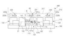
도 7은 본 발명의 스위치장치에서 일 실시예에 따른 베이스측 자석세트 및 조작모듈의 제1자석 사이의 관계를 도시한 도면으로, 이동자석이 홀드위치에 위치한 것을 나타낸다.
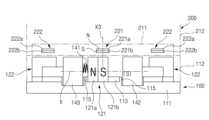
도 8은 본 발명의 스위치장치에서 일 실시예에 따른 베이스측 자석세트 및 조작모듈의 제1자석 사이의 관계를 도시한 도면으로, 이동자석이 해제가능위치에 위치한 것을 나타낸다.
도 9는 본 발명의 스위치장치에서 다른 실시예에 따른 베이스측 자석세트 및 조작모듈의 제1자석 사이의 관계를 도시한 도면으로, 이동자석이 홀드위치에 위치한 것을 나타낸다.
도 10은 본 발명의 스위치장치에서 다른 실시예에 따른 베이스측 자석세트 및 조작모듈의 제1자석 사이의 관계를 도시한 도면으로, 이동자석이 해제가능위치에 위치한 것을 나타낸다.
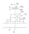
도 11은 본 발명의 스위치장치에서 일 실시예에 따른 베이스측 자석세트의 고정자석 및 조작모듈의 제2자석 사이의 관계를 도시한 도면이다.
도 12는 본 발명의 스위치장치에서 다른 실시예에 따른 베이스측 자석세트의 고정자석 및 조작모듈의 제2자석 사이의 관계를 도시한 도면이다.
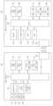
도 13은 본 발명의 실시예에 따른 스위치장치의 구체적인 구성을 도시한 도면이다.1 is a perspective view showing a switch device according to an embodiment of the present invention.
2 is an exploded perspective view showing a switch device according to an embodiment of the present invention.
3 is a plan view showing a base-side magnet set of a base module and an operation-side magnet set of an operation module of a switch device according to an embodiment of the present invention, showing that a moving magnet is located in a hold position.
4 is a perspective view showing a base-side magnet set of a base module and an operation-side magnet set of an operation module of a switch device according to an embodiment of the present invention, showing that a moving magnet is located in a hold position.
5 is a plan view showing a base-side magnet set of a base module and an operation-side magnet set of an operation module of a switch device according to an embodiment of the present invention, showing that the movable magnet is located in a releaseable position.
6 is a perspective view showing a base-side magnet set of a base module and an operation-side magnet set of an operation module of a switch device according to an embodiment of the present invention, showing that the movable magnet is located in a releaseable position.
7 is a view showing the relationship between a base-side magnet set and a first magnet of an operation module according to an embodiment in the switch device of the present invention, showing that the moving magnet is located in the hold position.
8 is a view showing a relationship between a base-side magnet set and a first magnet of an operation module according to an embodiment in the switch device of the present invention, showing that the movable magnet is located in a releaseable position.
9 is a view showing the relationship between a base-side magnet set and a first magnet of an operation module according to another embodiment in the switch device of the present invention, showing that the moving magnet is located in the hold position.
10 is a diagram showing the relationship between a base side magnet set and a first magnet of an operation module according to another embodiment in the switch device of the present invention, showing that the movable magnet is located in a releaseable position.
11 is a diagram showing the relationship between a fixed magnet of a base-side magnet set and a second magnet of an operation module according to an embodiment in the switch device of the present invention.
12 is a diagram showing the relationship between a fixed magnet of a base-side magnet set and a second magnet of an operation module according to another embodiment in the switch device of the present invention.
13 is a diagram showing a specific configuration of a switch device according to an embodiment of the present invention.
이하, 본 발명의 일부 실시예들을 예시적인 도면을 통해 상세하게 설명한다. 각 도면의 구성요소들에 참조부호를 부가함에 있어서, 동일한 구성요소들에 대해서는 비록 다른 도면상에 표시되더라도 가능한 한 동일한 부호를 가지도록 하고 있음에 유의해야 한다. 또한, 본 발명의 실시예를 설명함에 있어, 관련된 공지 구성 또는 기능에 대한 구체적인 설명이 본 발명의 실시예에 대한 이해를 방해한다고 판단되는 경우에는 그 상세한 설명은 생략한다.Hereinafter, some embodiments of the present invention will be described in detail through exemplary drawings. In adding reference numerals to components of each drawing, it should be noted that the same components have the same numerals as much as possible even if they are displayed on different drawings. In addition, in describing an embodiment of the present invention, if it is determined that a detailed description of a related known configuration or function hinders understanding of the embodiment of the present invention, the detailed description will be omitted.
본 발명의 실시예의 구성 요소를 설명하는 데 있어서, 제 1, 제 2, A, B, (a), (b) 등의 용어를 사용할 수 있다. 이러한 용어는 그 구성 요소를 다른 구성 요소와 구별하기 위한 것일 뿐, 그 용어에 의해 해당 구성 요소의 본질이나 차례 또는 순서 등이 한정되지 않는다. 또한, 다르게 정의되지 않는 한, 기술적이거나 과학적인 용어를 포함해서 여기서 사용되는 모든 용어들은 본 발명이 속하는 기술 분야에서 통상의 지식을 가진 자에 의해 일반적으로 이해되는 것과 동일한 의미를 가진다. 일반적으로 사용되는 사전에 정의되어 있는 것과 같은 용어들은 관련 기술의 문맥상 가지는 의미와 일치하는 의미를 가진 것으로 해석되어야 하며, 본 출원에서 명백하게 정의하지 않는 한, 이상적이거나 과도하게 형식적인 의미로 해석되지 않는다.In describing the components of the embodiment of the present invention, terms such as first, second, A, B, (a), and (b) may be used. These terms are only used to distinguish the component from other components, and the nature, order, or order of the corresponding component is not limited by the term. In addition, unless defined otherwise, all terms used herein, including technical or scientific terms, have the same meaning as commonly understood by a person of ordinary skill in the art to which the present invention belongs. Terms such as those defined in commonly used dictionaries should be interpreted as having a meaning consistent with the meaning in the context of the related art, and unless explicitly defined in the present application, they should not be interpreted in an ideal or excessively formal meaning. don't
도 1을 참조하면, 본 발명의 실시예에 따른 스위치장치는, 베이스모듈(100)과, 자력의 가변을 통해 베이스모듈(100)에 분리가능하게 부착되는 조작모듈(200)을 포함할 수 있다.Referring to FIG. 1 , a switch device according to an embodiment of the present invention may include a
베이스모듈(100)은 차량의 다양한 위치(센터콘솔, 도어트림, 리어시트 콘솔 등)에 장착될 수 있고, 베이스모듈(100)은 차량 내의 다양한 장치에 전기적 및/또는 기계적으로 연결될 수 있다. 예컨대, 베이스모듈(100)은 도어래치메커니즘, 아웃사이드미러 조절기구, 시트 조절기구, 공조시스템, 조명시스템 등과 같은 차량의 다양한 장치에 전기적 및/또는 기계적으로 연결될 수 있다.The
베이스모듈(100)은 베이스 케이스(110)와, 베이스 케이스(110) 내에 수용된 베이스측 자석세트(120)를 포함할 수 있다. 도 2를 참조하면, 베이스 케이스(110)는 베이스 바디(111)와, 베이스 바디(111)를 커버하는 베이스 커버(112)를 포함할 수 있다. 베이스측 자석세트(120)는 베이스 바디(111)에 장착될 수 있고, 베이스 커버(112)가 베이스 바디(111)를 커버함으로써 베이스측 자석세트(120)는 베이스 케이스(110) 내에 수용될 수 있다.The
베이스측 자석세트(120)는 베이스 바디(111)에 이동가능하게 장착된 이동자석(121)을 포함할 수 있다.The base side magnet set 120 may include a moving
도 7 및 도 8을 참조하면, 이동자석(121)의 자장축(X1, magnetic axis)은 베이스 케이스(110)의 베이스 바디(111)의 평면과 평행하도록 연장될 수 있다. 이동자석(121)은 제1극성을 가진 제1부분(121a)과, 제2극성을 가진 제2부분(121b)을 포함할 수 있다. 제1극성과 제2극성은 서로 반대극성이다. 일 예에 따르면, 도 7 및 도 8과 같이 제1부분(121a)의 제1극성은 N극일 수 있고, 제2부분(121b)의 제2극성은 S극일 수 있다. 다른 예에 따르면 제1부분(121a)의 제1극성은 S극일 수 있고, 제2부분(121b)의 제2극성은 N극일 수 있다. 제1부분(121a)의 평면 및 제2부분(121b)의 평면은 이동자석(121)의 자장축(X1)에 대해 직교할 수 있다. 즉, 이동자석(121)의 자장축(X1)은 제1부분(121a)의 평면 및 제2부분(121b)의 평면에 직교하는 법선방향을 따라 연장될 수 있다.Referring to FIGS. 7 and 8 , a magnetic axis X1 of the moving
도 7 및 도 8을 참조하면, 베이스측 자석세트(120)는 이동자석(121)을 사이에 두고 대향적으로 배치된 제1전자석(125a) 및 제2전자석(125b)을 포함할 수 있다. 즉, 제1전자석(125a) 및 제2전자석(125b)은 이동자석(121)의 양측에 대향되게 배치될 수 있다. 특히, 제1전자석(125a)은 이동자석(121)의 제1부분(121a)을 향할 수 있고, 제2전자석(125b)은 이동자석(121)의 제2부분(121b)을 향할 수 있다.Referring to FIGS. 7 and 8 , the base side magnet set 120 may include a
전류가 정방향 또는 역방향으로 흐를 때, 이동자석(121)의 제1부분(121a)을 향하는 제1전자석(125a)의 단면 및 이동자석(121)의 제2부분(121b)을 향하는 제2전자석(125b)의 단면은 서로 동일한 극성을 가지도록 구성될 수 있다. 각 전자석(125a, 125b)으로 흐르는 전류의 방향이 변환됨에 따라 각 전자석(125a, 125b)은 그 극성이 변환될 수 있다. 각 전자석(125a, 125b)들의 극성들이 변환됨에 따라 이동자석(121)은 제1전자석(125a) 및 제2전자석(125b) 중에서 어느 하나의 전자석을 향해 이동하고 해당 전자석에 부착되거나 인접할 수 있다.When current flows in the forward or reverse direction, the end face of the
도 3, 도 4, 및 도 7을 참조하면, 제1전자석(125a)의 제1부분(121a)을 향하는 단면 및 제2전자석(125b)의 제2부분(121b)을 향하는 단면이 이동자석(121)의 제1부분(121a)과 동일한 극성인 제1극성으로 변환될 때, 이동자석(121)의 제1부분(121a) 및 제1전자석(125a)의 제1부분(121a)을 향하는 단면은 서로 동일한 극성을 가지므로 이동자석(121)의 제1부분(121a)과 제1전자석(125a) 사이에서 척력이 발생할 수 있고, 이동자석(121)의 제2부분(121b) 및 제2전자석(125b)의 제2부분(121b)을 향하는 단면은 서로 반대극성을 가지므로 이동자석(121)의 제2부분(121b)과 제2전자석(125b) 사이에서 인력이 발생할 수 있다. 이에 따라, 이동자석(121)은 제2전자석(125b)을 향해 이동할 수 있고, 이동자석(121)은 제2전자석(125b)에 부착되거나 근접할 수 있다. 즉, 이동자석(121)은 제2전자석(125b)을 향해 치우쳐 위치할 수 있다. 이와 같이, 이동자석(121)이 제2전자석(125b)을 향해 치우친 위치는 후술하는 바와 같이 홀드위치로 정의될 수 있다.3, 4, and 7, the end face of the
도 5, 도 6, 도 8을 참조하면, 제1전자석(125a)의 제1부분(121a)을 향하는 단면 및 제2전자석(125b)의 제2부분(121b)을 향하는 단면이 이동자석(121)의 제2부분(121b)과 동일한 제2극성으로 변환될 때, 이동자석(121)의 제1부분(121a) 및 제1전자석(125a)의 제1부분(121a)을 향하는 단면은 서로 반대극성을 가지므로 이동자석(121)의 제1부분(121a)과 제1전자석(125a) 사이에서 인력이 발생할 수 있고, 이동자석(121)의 제2부분(121b)과 제2전자석(125b)의 제2부분(121b)을 향하는 단면은 서로 동일한 극성을 가지므로 이동자석(121)의 제2부분(121b)과 제2전자석(125b) 사이에서 척력이 발생할 수 있다. 이에 따라, 이동자석(121)은 제1전자석(125a)을 향해 이동할 수 있고, 이동자석(121)은 제1전자석(125a)에 부착되거나 근접할 수 있다. 즉, 이동자석(121)은 제1전자석(125a)을 향해 치우쳐 위치할 수 있다. 이와 같이, 이동자석(121)이 제1전자석(125a)을 향해 치우친 위치는 후술하는 바와 같이 해제가능위치로 정의될 수 있다.5, 6, and 8, the cross section of the
도 3 내지 도 8을 참조하면, 베이스 바디(111)는 이동자석(121)의 이동경로를 한정하는 가이드부재(113)를 더 포함할 수 있다. 가이드부재(113)는 이동자석(121)의 위치를 홀드위치 및 해제가능위치로 규제하는 2개의 규제돌기(115)를 가질 수 있다. 이에, 이동자석(121)은 가이드부재(113)의 규제돌기(115)들에 의해 홀드위치 및 해제가능위치에서 규제될 수 있다.Referring to FIGS. 3 to 8 , the
베이스측 자석세트(120)는 베이스 바디(111)에 고정된 고정자석(122)을 더 포함할 수 있고, 고정자석(122)은 이동자석(121)에 대해 충분히 이격됨으로써 이동자석(121)의 자기장에 대해 영향을 받지 않도록 구성될 수 있다.The base-side magnet set 120 may further include a
도 11을 참조하면, 고정자석(122)의 자장축(X2)은 베이스 바디(111)의 평면과 평행하도록 연장될 수 있다. 고정자석(122)은 제1극성을 가진 제1부분(122a)과, 제2극성을 가진 제2부분(122b)을 포함할 수 있다. 제1극성과 제2극성은 서로 반대극성일 수 있다. 일 예에 따르면, 도 11과 같이 제1부분(122a)의 제1극성은 N극일 수 있고, 제2부분(122b)의 제2극성은 S극일 수 있다. 다른 예에 따르면 제1부분(122a)의 제1극성은 S극일 수 있고, 제2부분(122b)의 제2극성은 N극일 수 있다. 제1부분(122a)의 평면 및 제2부분(122b)의 평면은 고정자석(122)의 자장축(X2)에 대해 직교할 수 있다. 즉, 고정자석(122)의 자장축(X2)은 제1부분(122a)의 평면 및 제2부분(122b)의 평면에 직교하는 법선방향을 따라 연장될 수 있다.Referring to FIG. 11 , the magnetic field axis X2 of the
실시예에 따르면, 고정자석(122)의 제1부분(122a)의 제1극성은 이동자석(121)의 제1부분(121a)의 제1극성과 동일한 극성일 수 있고, 고정자석(122)의 제2부분(122b)의 제2극성은 이동자석(121)의 제2부분(121b)의 제2극성과 동일한 극성일 수 있다. 이동자석(121)의 자장축(X1) 및 고정자석(122)의 자장축(X2)은 수평방향으로 연장될 수 있다.According to the embodiment, the first polarity of the
조작모듈(200)은 제2케이스(210)와, 제2케이스(210) 내에 수용된 제2자석세트(220)를 포함할 수 있다. 도 2를 참조하면, 조작 케이스(210)는 서포트(211)와, 서포트(211)를 커버하는 조작 바디(212)를 포함할 수 있다. 조작측 자석세트(220)는 서포트(211)에 장착될 수 있고, 조작 바디(212)가 서포트(211)를 커버함으로써 조작측 자석세트(220)는 조작 케이스(210) 내에 수용될 수 있다.The
실시예에 따르면, 서포트(211)는 조작측 자석세트(220) 및 베이스측 자석세트(120) 사이의 자력 변화를 통해 베이스모듈(100)의 베이스 커버(112)에 분리가능하게 부착될 수 있다. 특히, 서포트(211)가 조작측 자석세트(220) 및 베이스측 자석세트(120) 사이의 인력에 의해 베이스모듈(100)의 베이스 커버(112)에 부착될 때, 서포트(211)는 베이스모듈(100)에 대해 고정적으로 유지될 수 있다(retained stationary). 조작 바디(212)는 베어링, 부싱 등을 통해 서포트(211)에 대해 회전가능하게 장착될 수 있다. 특히, 조작 바디(212)는 그의 회전축선(Z) 둘레로 회전가능하게 구성될 수 있다. 이에, 조작모듈(200)은 조작 바디(212)의 회전에 의해 다양한 장치에 대한 다양한 조작을 실행할 수 있다.According to the embodiment, the
조작측 자석세트(220)는 서포트(211)에 고정된 제1자석(221)을 포함할 수 있고, 제1자석(221)은 베이스모듈(100)의 이동자석(121)의 위에 위치할 수 있다.The manipulation side magnet set 220 may include a
제1자석(221)의 자장축(X3)은 서포트(211)의 평면과 직교하는 법선방향을 따라 연장될 수 있다. 제1자석(221)은 제1극성을 가진 제1부분(221a)과, 제2극성을 가진 제2부분(221b)을 포함할 수 있다. 제1극성과 제2극성은 서로 반대극성일 수 있다. 일 예에 따르면, 도 7 및 도 8과 같이 제1부분(221a)의 제1극성은 N극일 수 있고, 제2부분(221b)의 제2극성은 S극일 수 있다. 다른 예에 따르면 제1부분(221a)의 제1극성은 S극일 수 있고, 제2부분(221b)의 제2극성은 N극일 수 있다.The magnetic field axis X3 of the
제1부분(221a)의 평면 및 제2부분(221b)의 평면은 제1자석(221)의 자장축(X3)에 대해 직교할 수 있다. 즉, 제1자석(221)의 자장축(X3)은 제1부분(221a)의 평면 및 제2부분(221b)의 평면에 직교하는 법선방향을 따라 연장될 수 있다.The plane of the
도 7 및 도 8을 참조하면, 제1자석(221)의 자장축(X3)은 서포트(211)의 평면과 직교하는 법선방향을 따라 연장될 수 있다. 제1자석(221)은 제1극성을 가진 제1부분(221a)과, 제2극성을 가진 제2부분(221b)을 포함할 수 있다. 제1극성과 제2극성은 서로 반대극성일 수 있다. 일 예에 따르면, 도 7 및 도 8과 같이 제1부분(221a)의 제1극성은 N극일 수 있고, 제2부분(221b)의 제2극성은 S극일 수 있다. 다른 예에 따르면 제1부분(221a)의 제1극성은 S극일 수 있고, 제2부분(221b)의 제2극성은 N극일 수 있다. 제1부분(221a)의 평면 및 제2부분(221b)의 평면은 제1자석(221)의 자장축(X3)에 대해 직교할 수 있다. 즉, 제1자석(221)의 자장축(X3)은 제1부분(221a)의 평면 및 제2부분(221b)의 평면에 직교하는 법선방향을 따라 연장될 수 있다.Referring to FIGS. 7 and 8 , the magnetic field axis X3 of the
도 7 및 도 8을 참조하면, 제1자석(221)의 제1부분(221a)의 제1극성은 이동자석(121)의 제1부분(121a)의 제1극성과 동일할 수 있고, 제1자석(221)의 제2부분(221b)의 제2극성은 이동자석(121)의 제2부분(121b)의 제2극성과 동일할 수 있다.7 and 8, the first polarity of the
제1자석(221)은 이동자석(121)의 이동경로 위에 위치할 수 있다. 구체적으로, 조작모듈(200)의 제1자석(221)의 제2부분(221b)은 베이스모듈(100)의 이동자석(121)의 이동경로를 향할 수 있다. 이에 이동자석(121)이 제1전자석(125a) 및 제2전자석(125b) 사이에서 이동할 때, 이동자석(121)의 제1부분(121a) 및 제2부분(121b) 중에서 적어도 하나가 조작모듈(200)의 제1자석(221)과 마주볼 수 있다.The
도 7을 참조하면, 전류가 정방향으로 흐를때, 제1전자석(125a) 및 제2전자석(125b)은 이동자석(121)의 제1부분(121a)과 동일한 극성인 제1극성(N극성)을 가질 수 있고, 이에 이동자석(121)의 제2부분(121b)이 제2전자석(125b)을 향해 이동할 수 있으며, 조작모듈(200)의 제1자석(221)의 제2부분(221b)이 베이스모듈(100)의 이동자석(121)의 제1부분(121a)과 마주볼 수 있다. 특히, 조작모듈(200)의 제1자석(221)의 제2부분(221b) 및 베이스모듈(100)의 이동자석(121)의 제1부분(121a)은 서로 반대극성을 가지므로 조작모듈(200)의 제1자석(221)의 제2부분(221b) 및 베이스모듈(100)의 이동자석(121)의 제1부분(121a) 사이에서 인력이 발생할 수 있다.Referring to FIG. 7, when current flows in the forward direction, the
도 8을 참조하면, 전류가 역방향으로 흐를때, 제1전자석(125a) 및 제2전자석(125b)은 이동자석(121)의 제2부분(121b)과 동일한 극성인 제2극성(S극성)을 가질 수 있고, 이에 이동자석(121)의 제2부분(121b)이 제1전자석(125a)을 향해 이동할 수 있으며, 조작모듈(200)의 제1자석(221)의 제2부분(221b)은 베이스모듈(100)의 이동자석(121)의 제2부분(121b)과 마주볼 수 있다. 특히, 조작모듈(200)의 제1자석(221)의 제2부분(221b) 및 베이스모듈(100)의 이동자석(121)의 제2부분(121b)은 서로 동일한 극성을 가지므로 조작모듈(200)의 제1자석(221)의 제2부분(221b) 및 베이스모듈(100)의 이동자석(121)의 제2부분(121b) 사이에서 척력이 발생할 수 있다.Referring to FIG. 8, when the current flows in the reverse direction, the
상술한 바와 같이, 이동자석(121)은 홀드위치(hold position) 및 해제가능위치(releasable position) 사이로 이동하도록 구성될 수 있다. 홀드위치(도 3, 도 4, 및 도 7 참조)는 이동자석(121)과 조작모듈(200)의 제1자석(221) 사이에서 인력이 작용함으로써 조작모듈(200)이 베이스모듈(100)에 부착됨을 유지하는 위치일 수 있고, 해제가능위치(도 5, 도 6, 및 도 8 참조)는 이동자석(121)과 조작모듈(200)의 제1자석(221) 사이에서 척력이 발생함으로써 조작모듈(200)이 베이스모듈(100)로부터 분리가능한 위치일 수 있다.As described above, the moving
이동자석(121)이 홀드위치에 위치할 때, 조작모듈(200)의 제1자석(221)의 제2부분(221b)은 베이스모듈(100)의 이동자석(121)의 제1부분(121a)과 마주볼 수 있고, 이에 조작모듈(200)의 제1자석(221)의 제2부분(221b) 및 베이스모듈(100)의 이동자석(121)의 제1부분(121a) 사이에서 인력이 발생함으로써 조작모듈(200)은 베이스모듈(100)에 부착됨을 유지할 수 있다.When the moving
이동자석(121)이 해제가능위치에 위치할 때, 조작모듈(200)의 제1자석(221)의 제2부분(221b)은 베이스모듈(100)의 이동자석(121)의 제2부분(121b)과 마주볼 수 있고, 이에 조작모듈(200)의 제1자석(221)의 제2부분(221b) 및 베이스모듈(100)의 이동자석(121)의 제2부분(121b) 사이에서 척력이 발생함으로써 조작모듈(200)은 베이스모듈(100)에 대해 분리가능하다.When the moving
일 예에 따르면, 제1전자석(125a) 및 제2전자석(125b)은 자기코어 및 자기코어의 둘레에 감겨진 코일을 포함할 수 있다. 전류가 코일을 따라 일방향으로 흐름에 따라 제1전자석(125a) 및 제2전자석(125b)에 자기장이 형성될 수 있다. 즉, 제1전자석(125a) 및 제2전자석(125b)는 일정한 극성을 가지도록 자화될 수 있다. 자기코어가 철(iron) 등과 같이 강자성체인 경우, 전류가 일방향으로 흐름에 따라 제1전자석(125a) 및 제2전자석(125b)이 자화된 이후에 전류가 제1전자석(125a) 및 제2전자석(125b)에 흐르지 않더라도 제1전자석(125a) 및 제2전자석(125b)은 잔류자기(Residual Magnetism)에 의해 전류가 그 반대방향으로 흐르기 전까지 그 자성이 일정하게 유지될 수 있다. 즉, 전류가 제1전자석(125a) 및 제2전자석(125b)에 일정방향으로 흐른 이후에, 전류가 그 반대방향으로 흐르기 전까지는 이동자석(121)은 홀드위치 또는 해제가능위치를 유지할 수 있다.According to an example, the
도 9 및 도 10은 다른 실시예에 따른 베이스측 자석세트를 도시한 도면이다. 도 9 및 도 10을 참조하면, 다른 실시예에 따른 베이스측 자석세트는 이동자석(121)을 사이에 두고 대향적으로 배치된 스프링(141) 및 전자석(142)을 포함할 수 있다. 즉, 스프링(141) 및 전자석(142)이 이동자석(121)의 양측에 대향되게 배치됨으로써 이동자석(121)은 스프링(141)의 스프링력 및 전자석(142)의 자력에 의해 홀드위치 및 해제가능위치 사이로 선택적으로 이동하도록 구성될 수 있다.9 and 10 are diagrams showing a base-side magnet set according to another embodiment. Referring to FIGS. 9 and 10 , a base-side magnet set according to another embodiment may include a
스프링(141)은 이동자석(121)을 홀드위치로 편향시키는 스프링력을 제공하도록 구성될 수 있다. 스프링(141)은 리테이너(143) 및 이동자석(121)의 제1부분(121a) 사이에 개재될 수 있고, 리테이너(143)는 전자석(142)에 대향하도록 배치될 수 있다. 스프링(141)의 제1단부는 리테이너(143)에 대해 지지될 수 잇고, 스프링(141)의 제2단부는 이동자석(121)의 제1부분(121a)에 대해 지지될 수 있다. The
도 9를 참조하면, 스프링(141)이 이동자석(121)을 전자석(142)을 향해 밀어내는 탄성력을 제공함에 따라 전자석(142)에 전류가 흐르지 않을 비여자될 때), 이동자석(121)은 전자석(142)을 향해 편향될 수 있고, 이에 이동자석(121)의 제1부분(121a)은 조작모듈(200)의 제1자석(221)의 제2부분(221b)과 마주볼 수 있으며, 이동자석(121)의 제1부분(121a)과 제1자석(221)의 제2부분(221b) 사이에 인력이 발생할 수 있다. 즉, 스프링(141)은 이동자석(121)을 홀드위치로 편향시킴으로써 이동자석(121)과 조작모듈(200)의 제1자석(221) 사이에서 인력이 발생할 수 있고, 이에 조작모듈(200)은 베이스모듈(100)에 부착됨을 유지할 수 있다.Referring to FIG. 9, as the
도 10을 참조하면, 전자석(142)이 이동자석(121)의 제2부분(221b)의 제2극성과 동일한 극성을 가지도록 전류가 전자석(142)에 흐를때(전자석(142)이 여자될 때), 전자석(142)과 이동자석(121)의 제2부분(221b) 사이에서 척력이 발생할 수 있고, 이에 발생된 척력이 스프링(141)의 스프링력을 극복할 때 이동자석(121)은 리테이너(143)를 향해 이동할 수 있다. 이에, 이동자석(12)의 제2부분(121b)이 조작모듈(200)의 제1자석(221)의 제2부분(221b)과 마주볼 수 있으므로 이동자석(121)의 제2부분(121b)과 제1자석(221)의 제1부분(221b) 사이에서 척력이 발생할 수 있다. 즉, 전자석(142)은 이동자석(121)을 해제가능위치로 편향시킴으로써 이동자석(121)과 조작모듈(200)의 제1자석(221) 사이에서 척력을 발생할 수 있고, 이에 조작모듈(200)은 베이스모듈(100)로부터 분리가능하다.10, when a current flows through the
이와 같이, 이동자석(121)의 제1부분(121a)은 스프링(141)과 직접적으로 접촉할 수 있고, 이동자석(121)의 제2부분(121b)은 전자석(142)을 향할 수 있다. 또한, 전자석(142)은 이동자석(121)의 제2부분(121b)의 제2극성과 동일한 극성을 가지도록 여자될 수 있다.As such, the
조작측 자석세트(220)는 서포트(211)에 고정된 제2자석(222)을 더 포함할 수 있고, 제2자석(222)은 베이스모듈(100)의 고정자석(122)의 위에 고정적으로 위치할 수 있다.The operation side magnet set 220 may further include a
도 2를 참조하면, 제2자석(222)의 자장축(X4)은 서포트(211)의 평면에 대해 직교하는 방향을 따라 연장될 수 있다. 제2자석(222)은 제1극성을 가진 제1부분(222a)과, 제2극성을 가진 제2부분(222b)을 포함할 수 있다. 제1극성과 제2극성은 서로 반대극성일 수 있다. 일 예에 따르면, 도 11과 같이 제1부분(222a)의 제1극성은 N극일 수 있고, 제2부분(222b)의 제2극성은 S극일 수 있다. 다른 예에 따르면 제2부분(222a)의 제1극성은 S극일 수 있고, 제2부분(222b)의 제2극성은 N극일 수 있다. 제1부분(222a)의 평면 및 제2부분(222b)의 평면은 제2자석(222)의 자장축(X4)에 대해 직교할 수 있다. 즉, 제2자석(222)의 자장축(X4)은 제1부분(222a)의 평면 및 제2부분(222b)의 평면에 직교하는 법선방향을 따라 연장될 수 있다.Referring to FIG. 2 , the magnetic field axis X4 of the
실시예에 따르면, 제2자석(222)의 제1부분(222a)의 제1극성은 베이스모듈(100)의 고정자석(122)의 제1부분(122a)의 제1극성과 동일할 수 있고, 제2자석(222)의 제2부분(222b)의 제2극성은 베이스모듈(100)의 고정자석(122)의 제2부분(122b)의 제2극성과 동일할 수 있다.According to the embodiment, the first polarity of the
실시예에 따르면, 제2자석(222)의 제1부분(222a)의 제1극성은 제1자석(221)의 제1부분(221a)의 제1극성과 동일한 극성일 수 있고, 제2자석(222)의 제2부분(222b)의 제2극성은 제1자석(221)의 제2부분(221b)의 제2극성과 동일한 극성일 수 있다. 도 2를 참조하면, 제1자석(221)의 자장축(X3) 및 제2자석(222)의 자장축(X4)은 수직방향으로 연장될 수 있다.According to the embodiment, the first polarity of the
도 11을 참조하면, 제2자석(222)의 제2부분(222b)은 베이스모듈(100)의 고정자석(122)의 제1부분(122a)과 마주보도록 배치될 수 있다. 이에, 조작모듈(200)의 제2자석(222) 및 베이스모듈(100)의 고정자석(122) 사이에서 항상 인력이 발생할 수 있다. 제2자석(222)의 자장축(X4)은 고정자석(122)의 자장축(X2)과 직교할 수 있다.Referring to FIG. 11 , the
도 12는 다른 실시예에 따른 베이스측 자석세트의 고정자석(132)을 도시한 도면이다. 도 12를 참조하면, 고정자석(132)의 자장축(X5)은 베이스 바디(111)의 평면에 대해 직교한 법선방향을 따라 연장될 수 있다. 이에, 조작모듈(200)의 제2자석(222)의 자장축(X4)은 베이스모듈(100)의 고정자석(132)의 자장축(X5)에 정렬되거나 평행할 수 있다. 제2자석(222)의 제2부분(222b)이 베이스모듈(100)의 고정자석(132)의 제1부분(132a)과 마주보도록 배치될 수 있다. 이에, 조작모듈(200)의 제2자석(222) 및 베이스모듈(100)의 고정자석(132) 사이에서 항상 인력이 작용할 수 있다.12 is a view showing a
도 1 내지 도 6을 참조하면, 베이스모듈(100) 및 조작모듈(200)은 제1공통 수평축선(O1) 및 제2공통 수평축선(02)을 개별적으로 가질 수 있고, 제1공통 수평축선(01) 및 제2공통 수평축선(O2)은 베이스 바디(111)의 평면 및 서포트(211)의 평면에 평행할 수 있다. 제1공통 수평축선(O1)은 제2공통 수평축선(O2)에 대해 직교할 수 있다.1 to 6, the
도 2 내지 도 6을 참조하면, 베이스측 자석세트(120)는 한 쌍의 이동자석(121)을 포함할 수 있고, 한 쌍의 이동자석(121)은 제1공통 수평축선(O1)을 따라 이격될 수 있으며, 각 이동자석(121)은 베이스 바디(111)의 가장자리에서 이동가능하게 장착될 수 있다. 특히, 한 쌍의 이동자석(121)은 제2공통 수평축선(02)을 기준으로 대향적으로 배열될 수 있다. 도 3 내지 도 6을 참조하면, 좌측의 이동자석(121)의 제1부분(121a) 및 우측의 이동자석(121)의 제1부분(121a)은 제1공통 수평축선(O1)을 기준으로 서로 반대방향을 향할 수 있다.2 to 6, the base side magnet set 120 may include a pair of
도 2 내지 도 6을 참조하면, 베이스측 자석세트(120)는 한 쌍의 고정자석(122)을 포함할 수 있고, 한 쌍의 고정자석(122)은 제2공통 수평축선(O2)을 따라 이격될 수 있으며, 각 고정자석(122)은 베이스 바디(111)의 가장자리에 고정적으로 장착될 수 있다. 특히, 한 쌍의 고정자석(122)은 제1공통 수평축선(O1)을 기준으로 대향적으로 배열될 수 있다. 도 3 내지 도 6을 참조하면, 상측의 고정자석(122)의 제1부분(122a) 및 하측의 고정자석(122)의 제1부분(122a)은 제2공통 수평축선(O2)을 기준으로 서로 반대방향을 향할 수 있다.2 to 6, the base side magnet set 120 may include a pair of
도 2 내지 도 6을 참조하면, 조작측 자석세트(220)는 한 쌍의 제1자석(221)을 포함할 수 있고, 한 쌍의 제1자석(221)은 제1공통 수평축선(O1)을 따라 이격될 수 있다. 각 제1자석(221)은 서포트(211)의 가장자리에 고정적으로 장착될 수 있다. 특히, 한 쌍의 제1자석(221)은 제2공통 수평축선(02)을 기준으로 대향적으로 배열될 수 있다. 도 3 내지 도 6을 참조하면, 좌측의 제1자석(221)은 제1공통 수평축선(O1)을 따라 우측의 제1자석(221)에 정렬될 수 있다.2 to 6 , the manipulation-side magnet set 220 may include a pair of
도 2 내지 도 6을 참조하면, 조작측 자석세트(220)는 한 쌍의 제2자석(222)을 포함할 수 있고, 한 쌍의 제2자석(222)은 제2공통 수평축선(O2)을 따라 이격될 수 있다. 각 제2자석(222)은 서포트(211)의 가장자리에 고정적으로 장착될 수 있다. 특히, 한 쌍의 제2자석(222)은 제1공통 수평축선(01)을 기준으로 대향적으로 배열될 수 있다. 도 3 내지 도 6을 참조하면, 상측의 제2자석(222)은 제2공통 수평축선(O2)을 따라 하측의 제2자석(222)에 정렬될 수 있다.2 to 6 , the manipulation-side magnet set 220 may include a pair of
이와 같이, 한 쌍의 이동자석(121) 및 한 쌍의 고정자석(122)은 서로 직교하는 공통 수평축선(01, 02)들을 따라 대칭적으로 배열되고, 한 쌍의 제1자석(221) 및 한 쌍의 제2자석(222)은 서로 직교하는 공통 수평축선(O1, 02)들을 따라 대칭적으로 배열됨으로써 조작모듈(200)은 베이스모듈(100)에 견고하게 부착되거나 베이스모듈(100)로부터 용이하게 분리될 수 있다.As such, the pair of moving
베이스모듈(100)의 베이스측 자석세트(120) 및 조작모듈(200)의 조작측 자석세트(220) 사이에서 발생된 자력의 합력(Ft)의 크기에 따라 조작모듈(200)은 베이스모듈(100)로부터 분리되거나 부착될 수 있다.Depending on the magnitude of the resultant force (Ft) of the magnetic force generated between the base-side magnet set 120 of the
자력의 합력(Ft)은 베이스측 자석세트(120) 및 조작측 자석세트(220) 사이에서 발생된 인력(F1)과, 베이스측 자석세트(120) 및 조작측 자석세트(220) 사이에서 발생된 척력(-F2)과, 조작모듈(200)의 자중(W)을 합한 것이다(Ft= F1-F2+W).The resultant magnetic force (Ft) is generated between the attractive force (F1) generated between the base-side magnet set 120 and the manipulation-side magnet set 220, and between the base-side magnet set 120 and the manipulation-side magnet set 220. It is the sum of the repulsive force (-F2) and the self-weight (W) of the control module 200 (Ft = F1-F2 + W).
자력의 합력(Ft)이 0보다 클 때(Ft > 0), 베이스모듈(100)과 조작모듈(200) 사이에서 충분한 인력이 작용하는 것이고, 이에 조작모듈(200)은 베이스모듈(100)에 대해 부착됨을 유지할 수 있다.When the resultant force (Ft) of the magnetic force is greater than 0 (Ft > 0), sufficient attractive force acts between the
자력의 합력(Ft)이 0일 때(Ft = 0), 베이스모듈(100)과 조작모듈(200) 사이에서 인력과 척력이 서로 간에 상쇄되고, 이에 조작모듈(200) 및 베이스모듈(100) 사이에서 자력이 작용하지 않으므로 조작모듈(200)이 베이스모듈(100)로부터 용이하게 분리될 수 있다. 예컨대, 베이스모듈(100)의 이동자석(121)이 해제가능위치에 위치할 때, 베이스모듈(100)의 이동자석(121)과 조작모듈(200)의 제1자석(221) 사이에서 발생한 척력이 베이스모듈(100)의 고정자석(122)과 조작모듈(200)의 제2자석(222) 사이에서 발생한 인력 및 조작모듈(200)의 자중(W)의 합과 동일할 때, 자력의 합력(Ft)은 0이 될 수 있다.When the resultant force (Ft) of the magnetic force is 0 (Ft = 0), the attractive force and the repulsive force between the
자력의 합력(Ft)이 0보다 작을 때(Ft < 0), 베이스모듈(100)과 조작모듈(200) 사이에서 충분한 척력이 작용하는 것이고, 이에 조작모듈(200)은 베이스모듈(100)로부터 미세한 간격으로 부상할 수 있으므로 조작모듈(200)은 베이스모듈(100)에 대해 그 이동(회전)이 용이해짐으로써 조작모듈(200)의 다양한 조작이 간편해질 수 있다. 예컨대, 베이스모듈(100)의 이동자석(121)이 해제가능위치에 위치할 때, 베이스모듈(100)의 이동자석(121)과 조작모듈(200)의 제1자석(221) 사이에서 발생한 척력이 베이스모듈(100)의 고정자석(122)과 조작모듈(200)의 제2자석(222) 사이에서 발생한 인력 및 조작모듈(200)의 자중(W)의 합 보다 클 때, 자력의 합력(Ft)은 0 보다 작을 수 있다.When the resultant force (Ft) of the magnetic force is less than 0 (Ft < 0), a sufficient repulsive force acts between the
일 실시예에 따르면, 조작모듈(200)은 제어기(250), 배터리(251), 디스플레이(252), 복수의 센서(253, 254), 조명모듈(255), 통신모듈(256), 햅틱모듈(257), 무선충전모듈(258), 무선충전코일(259)을 포함할 수 있다.According to one embodiment, the
조작모듈(200)은 레귤레이터를 더 포함할 수 있으며, 조작모듈(200)을 구성하는 적어도 하나 이상의 구성은 레귤레이터로부터 안정된 전압(전력)을 제공 받을 수 있다.The
배터리(251)는 전기 에너지를 저장할 수 있으며, 배터리(251)는 조작 제어기(250)를 통해 디스플레이(252), 복수의 센서(253, 254), 조명모듈(255), 통신모듈(256) 및 햅틱모듈(257) 중 적어도 하나 이상에 전기 에너지를 제공할 수 있다.The
디스플레이(252)는 조작모듈(200)의 조작 바디(212)의 상면에 배치될 수 있고, 터치 입력이 가능한 디스플레이를 포함할 수 있다.The display 252 may be disposed on an upper surface of the
각 센서(253, 254)는 가속도 센서, 자이로 센서, 터치 센서 및 압력 센서 중에서 적어도 어느 하나일 수 있다.Each of the
조명모듈(255)은 조작모듈(200)의 특정 부분에 라이팅 표시를 할 수 있다.The
통신모듈(256)은 조작모듈(200)의 입력을 유/무선 통신을 이용하여 베이스모듈(100)에 전달하도록 구성될 수 있다.The
햅틱모듈(257)은 조작모듈(200)의 터치 입력이 제대로 입력되었는지 촉각적으로 확인할 수 있도록, 진동의 세기 및 유지 시간의 조합에 따라 상이한 패턴의 진동을 발생시킬 수 있다.The haptic module 257 may generate vibrations of different patterns according to a combination of intensity and holding time of the vibrations so as to tactilely confirm whether the touch input of the
무선충전모듈(258) 및 무선충전코일(259)은 전자기 유도 현상을 이용하여 베이스모듈(100)로부터 발생되는 자기장을 수신하고, 수신된 자기장에 기초하여 전류를 생성할 수 있다.The
조작모듈(200)의 제어기(250)는 무선충전모듈(258)로부터 제공되는 전류를 이용하여 배터리(251)를 충전시키거나, 디스플레이(252), 복수의 센서(253, 254), 조명모듈(255), 통신모듈(256) 및 햅틱모듈(257) 중 적어도 하나 이상에 전류를 제공할 수 있다.The
또한, 조작모듈(200)의 제어기(250)는 디스플레이(252) 및 복수의 센서(253, 254)로부터 운전자 또는 탑승자의 입력을 수신하여 통신모듈(256)을 통해 베이스모듈(100)에 전달할 수 있다.In addition, the
조작모듈(200)의 제어기(250)가 디스플레이(252) 및 조명모듈(255)을 제어함으로써 시각정보가 운전자 또는 탑승자에게 제공될 수 있고, 조작모듈(200)의 제어기(250)가 햅틱모듈(257)을 제어함으로써 촉각정보가 운전자 또는 탑승자에게 제공될 수 있다.The
도 13을 참조하면, 베이스모듈(100)은 제어기(150), 레귤레이터(151), 기능스위치(152), CAN 통신모듈(153), 조명모듈(154), 통신모듈(155), 무선충전모듈(156), 무선충전코일(157), 및 복수의 포트(161, 162, 163, 164)를 포함할 수 있다.Referring to FIG. 13, the
레귤레이터(151)는 기설정된 레벨의 안정된 전압을 기능스위치(152), CAN 통신모듈(153), 조명모듈(154), 통신모듈(155), 무선충전모듈(156), 및 베이스 제어기(150) 중 적어도 하나에 제공할 수 있다.The
기능스위치(152)는 차량에 배치된 장치들의 제어에 필요한 스위치 또는 본 발명의 실시예에 따른 스위치장치의 기능 중 하나를 선택하는 스위치를 포함할 수 있다.The
CAN 통신모듈(153)은 차량의 내부에 배치된 다양한 전자장치들과 데이터, 정보 및 신호등을 송수신할 수 있다.The
조명모듈(154)은 베이스모듈(100)의 특정 부분을 밝히도록 구성된다. 예를 들어, 조명모듈(154)은 베이스모듈(100)의 베이스 커버(112)의 상면에서 조작모듈(200)이 부착되는 위치를 밝히도록 구성될 수 있다.The
통신모듈(155)은 조작모듈(200)의 통신모듈(256)과 데이터, 정보 및 신호등을 송수신할 수 있다. 이때, 블루투스, NFC(Near Field Communication) 및 와이파이와 같은 무선 통신 기술이 이용될 수도 있고, 시리얼 통신과 같은 유선 통신 기술이 이용될 수도 있다.The
무선충전모듈(156) 및 무선충전코일(157)은 베이스모듈(100)의 제어기(150)에 의해 자기장을 발생할 수 있다.The
베이스모듈(100)의 제어기(150)는 기능스위치(152)로부터 입력되는 운전자 또는 탑승자의 입력 및 CAN 통신모듈(153)로부터 수신되는 차량의 내부 전자 장치의 데이터 및 신호를 조작모듈(200)에 전달하거나, 기능스위치(152)로부터 입력되는 운전자 또는 탑승자의 입력 및 운전자 또는 탑승자의 조작모듈(200) 조작에 따른 정보를 차량 내부 전자 장치들에 전달할 수 있다.The
또한, 베이스모듈(100)의 제어기(150)는 조작모듈(200)로부터 제공되는 데이터, 정보 및 신호 등을 CAN 통신모듈(153)을 통해 차량의 내부 전자 장치에 전달할 수 있다.In addition, the
조작모듈(200)이 베이스모듈(100)에 근접하거나 부착되면(즉, 베이스모듈(100)과 조작모듈(200) 사이의 거리가 기설정된 거리 이하이면) 베이스모듈(100)의 제어기(150)는 무선충전모듈(156)을 제어함으로써 자기장이 무선충전코일(157)로부터 발생될 수 있다.When the
복수의 포트(161, 162, 163, 164)는 전원 단자(161, B+), 시동 확인 정보 수신 단자(162, IG), CAN 통신단자(163, CAN) 및 접지단자(164, GND)를 포함할 수 있다. 이때, 복수의 포트(161, 162, 163 및 164) 중 일부는 레귤레이터(151), 기능스위치(152), CAN 통신모듈(153), 조명모듈(154), 통신모듈(155) 및 무선충전모듈(156) 중 적어도 하나 이상과 전기적으로 연결될 수 있다.The plurality of ports (161, 162, 163, 164) includes a power terminal (161, B+), a start confirmation information receiving terminal (162, IG), a CAN communication terminal (163, CAN), and a ground terminal (164, GND). can do. At this time, some of the plurality of
조작모듈(200)의 제어기(250)는 조작모듈(200)이 베이스모듈(100)로부터 분리가능한 분리조건 및 조작모듈(200)이 베이스모듈(100)에 부착됨을 유지하는 부착조건 인지를 결정하도록 구성될 수 있다. 조작모듈(200)의 제어기(250)는 조작모듈(200)의 센서(253, 254)들로부터 수신받은 센싱정보에 기초하여 분리조건 및 부착조건을 결정할 수 있다.The
일 예에 따르면, 조작모듈(200)의 센서(253, 254) 중에서 어느 한 센서가 압력센서이고, 압력센서가 센싱한 압력이 설정압력 이상일 때 조작 제어기(250)는 분리조건을 결정할 수 있다.According to an example, when any one of the
다른 예에 따르면, 조작모듈(200)의 센서(253, 254) 중에서 어느 한 센서가 가속도센서 또는 자이로센서이고, 가속도센서 또는 자이로센서가 조작모듈(200)의 위치변화를 감지함으로써 조작모듈(200)의 제어기(250)는 분리조건을 결정할 수 있다.According to another example, any one of the
또 다른 예에 따르면, 조작모듈(200)의 센서(253, 254) 중에서 어느 한 센서가 터치센서이고, 분리조건이 터치센서에 입력됨으로써 조작모듈(200)의 제어기(250)는 분리조건을 결정할 수 있다.According to another example, any one of the
조작모듈(200)의 제어기(250)는 조작모듈(200)의 센서(253, 254)에 의해 판단된 분리조건을 무선통신 또는 유선통신 등을 통해 베이스모듈(100)의 제어기(150)로 전송할 수 있다.The
이상의 설명은 본 발명의 기술 사상을 예시적으로 설명한 것에 불과한 것으로서, 본 발명이 속하는 기술 분야에서 통상의 지식을 가진 자라면 본 발명의 본질적인 특성에서 벗어나지 않는 범위에서 다양한 수정 및 변형이 가능할 것이다.The above description is merely an example of the technical idea of the present invention, and various modifications and variations can be made to those skilled in the art without departing from the essential characteristics of the present invention.
따라서, 본 발명에 개시된 실시예들은 본 발명의 기술 사상을 한정하기 위한 것이 아니라 설명하기 위한 것이고, 이러한 실시예에 의하여 본 발명의 기술 사상의 범위가 한정되는 것은 아니다. 본 발명의 보호 범위는 아래의 청구범위에 의하여 해석되어야 하며, 그와 동등한 범위 내에 있는 모든 기술 사상은 본 발명의 권리범위에 포함되는 것으로 해석되어야 할 것이다.Therefore, the embodiments disclosed in the present invention are not intended to limit the technical idea of the present invention, but to explain, and the scope of the technical idea of the present invention is not limited by these embodiments. The protection scope of the present invention should be construed according to the claims below, and all technical ideas within the equivalent range should be construed as being included in the scope of the present invention.
100: 베이스모듈110: 베이스 케이스
111: 베이스 바디112: 베이스 커버
120: 베이스측 자석세트121: 이동자석
122, 132: 고정자석125a: 제1전자석
125b: 제2전자석141: 스프링
142: 전자석143: 리테이너
200: 조작모듈210: 조작 케이스
211: 서포트212: 조작 바디
221: 제1자석222: 제2자석100: base module 110: base case
111: base body 112: base cover
120: base side magnet set 121: moving magnet
122, 132:
125b: second electromagnet 141: spring
142: electromagnet 143: retainer
200: operation module 210: operation case
211: support 212: manipulation body
221: first magnet 222: second magnet
Claims (15)
Translated fromKorean조작 케이스와, 상기 조작 케이스 내에 고정적으로 장착된 제1자석을 포함한 조작모듈;을 포함하고,
상기 이동자석은 홀드위치 및 해제가능위치 사이로 이동하도록 구성되며,
상기 홀드위치는 상기 이동자석과 제1자석 사이에서 인력이 작용함으로써 상기 조작모듈이 상기 베이스모듈에 부착됨을 유지하는 위치이고,
상기 해제가능위치는 상기 이동자석과 제1자석 사이에서 척력이 작용함으로써 상기 조작모듈이 상기 베이스모듈로부터 분리가능한 위치인 스위치장치.
A base module including a base case and a moving magnet movably accommodated in the base case; and
A manipulation module including a manipulation case and a first magnet fixedly mounted in the manipulation case;
The moving magnet is configured to move between a hold position and a releaseable position,
The hold position is a position in which the operation module is maintained attached to the base module by an attractive force acting between the movable magnet and the first magnet,
The releasable position is a position in which the operation module can be separated from the base module by a repulsive force acting between the movable magnet and the first magnet.
상기 이동자석의 자장축은 상기 베이스 케이스의 평면과 평행하고, 상기 이동자석은 서로 반대극성을 가진 제1부분과 제2부분을 포함한 스위치장치.
The method of claim 1,
The magnetic field axis of the moving magnet is parallel to the plane of the base case, and the moving magnet includes a first part and a second part having opposite polarities.
상기 제1자석은 상기 이동자석의 이동경로 위에 위치하고, 상기 제1자석은 서로 반대극성을 가진 제1부분과 제2부분을 포함하며,
상기 제1자석의 자장축은 상기 이동자석의 자장축과 직교하도록 구성된 스위치장치.
The method of claim 2,
The first magnet is located on the moving path of the moving magnet, and the first magnet includes a first part and a second part having opposite polarities to each other,
A switch device configured so that the magnetic field axis of the first magnet is orthogonal to the magnetic field axis of the moving magnet.
상기 제1자석의 제1부분의 극성은 상기 이동자석의 제1부분의 극성과 동일하고, 상기 제1자석의 제2부분의 극성은 상기 이동자석의 제2부분의 극성과 동일한 스위치장치.
The method of claim 3,
The polarity of the first part of the first magnet is the same as the polarity of the first part of the moving magnet, and the polarity of the second part of the first magnet is the same as the polarity of the second part of the moving magnet.
상기 제1자석의 제2부분이 상기 이동자석의 이동경로를 향하도록 구성되고,
상기 이동자석이 상기 홀드위치에 위치할 때, 상기 제1자석의 제2부분은 상기 이동자석의 제1부분과 마주보도록 구성된 스위치장치.
The method of claim 3,
The second part of the first magnet is configured to face the moving path of the moving magnet,
When the moving magnet is positioned in the hold position, the second part of the first magnet faces the first part of the moving magnet.
상기 이동자석이 상기 해제가능위치에 위치할 때, 상기 제1자석의 제2부분은 상기 이동자석의 제2부분과 마주보도록 구성된 스위치장치.
The method of claim 5,
The switch device configured to face the second part of the first magnet with the second part of the first magnet when the moving magnet is located in the releasable position.
상기 조작모듈은 상기 이동자석의 양측에 대향되게 배치된 제1전자석 및 제2전자석를 더 포함하고,
상기 제1전자석은 상기 이동자석의 제1부분을 향하도록 구성되며, 상기 제2전자석은 상기 이동자석의 제2부분을 향하도록 구성되고,
전류의 방향이 변환됨에 따라 상기 제1전자석의 극성 및 상기 제2전자석의 극성은 변환되도록 구성된 스위치장치.
The method of claim 3,
The operation module further includes a first electromagnet and a second electromagnet disposed opposite to both sides of the moving magnet,
The first electromagnet is configured to face a first portion of the moving magnet, and the second electromagnet is configured to face a second portion of the moving magnet;
A switch device configured to change the polarity of the first electromagnet and the polarity of the second electromagnet as the direction of the current is changed.
상기 제1전자석의 극성 및 상기 제2전자석의 극성이 상기 이동자석의 제1부분의 극성과 동일해지도록 변환될 때, 상기 이동자석은 상기 홀드위치로 이동하도록 구성된 스위치장치.
The method of claim 7,
The switch device configured to move the moving magnet to the hold position when the polarity of the first electromagnet and the polarity of the second electromagnet are converted to become the same as the polarity of the first part of the moving magnet.
상기 제1전자석의 극성 및 상기 제2전자석의 극성이 상기 이동자석의 제2부분의 극성과 동일해지도록 변환될 때, 상기 이동자석은 상기 해제가능위치로 이동하도록 구성된 스위치장치.
The method of claim 7,
The switch device configured to move the moving magnet to the releasable position when the polarity of the first electromagnet and the polarity of the second electromagnet are converted to become the same as the polarity of the second part of the moving magnet.
상기 베이스모듈은 상기 이동자석의 양측에 대향되게 배치된 스프링과 전자석을 포함하고,
상기 스프링은 상기 이동자석의 제1부분을 향하도록 구성되며, 상기 전자석은 상기 이동자석의 제2부분을 향하도록 구성된 스위치장치.
The method of claim 3,
The base module includes a spring and an electromagnet disposed opposite to both sides of the moving magnet,
The switch device of claim 1 , wherein the spring is configured to face a first portion of the moving magnet, and the electromagnet is configured to face a second portion of the moving magnet.
상기 전자석이 비여자될 때, 상기 이동자석은 상기 스프링의 스프링력에 의해 상기 홀드위치로 이동하도록 구성된 스위치장치.
The method of claim 10,
The switch device configured to move the moving magnet to the hold position by the spring force of the spring when the electromagnet is de-energized.
상기 전자석이 여자될 때, 상기 이동자석은 상기 전자석의 자력에 의해 상기 해제가능위치로 이동하도록 구성된 스위치장치.
The method of claim 10,
When the electromagnet is excited, the moving magnet is configured to move to the releaseable position by the magnetic force of the electromagnet.
상기 베이스모듈은 상기 이동자석에 대해 이격된 고정자석을 더 포함하고,
상기 조작모듈은 상기 고정자석 위에 위치한 제2자석을 더 포함하며,
상기 제2자석 및 상기 고정자석은 그 사이에서 항상 인력이 발생하도록 구성된 스위치장치.
The method of claim 1,
The base module further includes a fixed magnet spaced apart from the moving magnet,
The operation module further includes a second magnet positioned above the stationary magnet,
The switch device configured to always generate an attractive force between the second magnet and the stationary magnet.
상기 제2자석의 자장축은 상기 고정자석의 자장축과 직교하도록 구성된 스위치장치.
The method of claim 13,
A switch device configured so that the magnetic field axis of the second magnet is orthogonal to the magnetic field axis of the stationary magnet.
상기 제2자석의 자장축은 상기 고정자석의 자장축과 평행하거나 정렬되도록 구성된 스위치장치.
The method of claim 13,
The magnetic field axis of the second magnet is configured to be parallel or aligned with the magnetic field axis of the stationary magnet.
Priority Applications (4)
| Application Number | Priority Date | Filing Date | Title |
|---|---|---|---|
| KR1020210136093AKR20230052727A (en) | 2021-10-13 | 2021-10-13 | Switch apparatus |
| US17/845,714US11978602B2 (en) | 2021-10-13 | 2022-06-21 | Switch apparatus |
| DE102022117336.4ADE102022117336A1 (en) | 2021-10-13 | 2022-07-12 | SWITCH DEVICE |
| CN202210824845.7ACN115966430A (en) | 2021-10-13 | 2022-07-13 | Switching device |
Applications Claiming Priority (1)
| Application Number | Priority Date | Filing Date | Title |
|---|---|---|---|
| KR1020210136093AKR20230052727A (en) | 2021-10-13 | 2021-10-13 | Switch apparatus |
Publications (1)
| Publication Number | Publication Date |
|---|---|
| KR20230052727Atrue KR20230052727A (en) | 2023-04-20 |
Family
ID=85705156
Family Applications (1)
| Application Number | Title | Priority Date | Filing Date |
|---|---|---|---|
| KR1020210136093APendingKR20230052727A (en) | 2021-10-13 | 2021-10-13 | Switch apparatus |
Country Status (4)
| Country | Link |
|---|---|
| US (1) | US11978602B2 (en) |
| KR (1) | KR20230052727A (en) |
| CN (1) | CN115966430A (en) |
| DE (1) | DE102022117336A1 (en) |
Families Citing this family (1)
| Publication number | Priority date | Publication date | Assignee | Title |
|---|---|---|---|---|
| CN113517152B (en)* | 2021-05-16 | 2022-08-16 | 武汉领普科技有限公司 | Switch control method, receiving end control method, self-generating switch and receiving end |
Family Cites Families (9)
| Publication number | Priority date | Publication date | Assignee | Title |
|---|---|---|---|---|
| US4599826A (en) | 1984-03-05 | 1986-07-15 | Institut Sverkhtverdykh Materialov Akademii Naukukrainskoi Ssr | Device for magnetoabrasive machining of workpieces |
| JP2001312949A (en) | 2000-04-21 | 2001-11-09 | Oa Tokukigyo Yugenkoshi | Magnet switch mechanism |
| JP4192267B2 (en) | 2003-05-21 | 2008-12-10 | ワッティー株式会社 | Self-holding proximity switch |
| DE20314364U1 (en) | 2003-09-16 | 2004-02-26 | Trw Automotive Electronics & Components Gmbh & Co. Kg | Rotary switch in a motor vehicle |
| US7800471B2 (en)* | 2008-04-04 | 2010-09-21 | Cedar Ridge Research, Llc | Field emission system and method |
| US8217742B2 (en) | 2008-10-07 | 2012-07-10 | Exelis, Inc. | Dual independent push button rotary knob assembly |
| KR101881339B1 (en) | 2017-06-01 | 2018-08-24 | 주식회사 디지티 | Magnetic knob assembly |
| KR102629518B1 (en) | 2018-08-13 | 2024-02-19 | (주)브이컴 | Latch switch mechanism and Apparatus using thereof |
| KR20220097696A (en) | 2020-12-30 | 2022-07-08 | 현대자동차주식회사 | Rotary switch apparatus for vehicle |
- 2021
- 2021-10-13KRKR1020210136093Apatent/KR20230052727A/enactivePending
- 2022
- 2022-06-21USUS17/845,714patent/US11978602B2/enactiveActive
- 2022-07-12DEDE102022117336.4Apatent/DE102022117336A1/enactivePending
- 2022-07-13CNCN202210824845.7Apatent/CN115966430A/enactivePending
Also Published As
| Publication number | Publication date |
|---|---|
| US20230114041A1 (en) | 2023-04-13 |
| CN115966430A (en) | 2023-04-14 |
| US11978602B2 (en) | 2024-05-07 |
| DE102022117336A1 (en) | 2023-04-13 |
Similar Documents
| Publication | Publication Date | Title |
|---|---|---|
| US10316554B2 (en) | Opening system for a vehicle | |
| US9958968B2 (en) | Input and output operation device | |
| EP3157157A1 (en) | System for levitating mobile terminal | |
| CN110461655A (en) | Rotary adjuster for vehicles | |
| US10013080B2 (en) | Manipulation apparatus | |
| US9595147B2 (en) | Vehicle input device | |
| KR20230052727A (en) | Switch apparatus | |
| WO2015104773A1 (en) | Input device | |
| WO2014174793A1 (en) | Input device | |
| US12015400B2 (en) | Rotary switch device for vehicle | |
| CN105849676A (en) | Input device | |
| US11660964B2 (en) | System and method for controlling functions of a vehicle using a detachable control device | |
| JP2008207655A (en) | Displacement device | |
| EP3916523B1 (en) | System, floating device, and a vehicle | |
| KR20190040548A (en) | Remote controller with force feedback using electromagnets | |
| JP2018102247A (en) | Autonomous vehicle | |
| JP2013020589A (en) | Apparatus moving system | |
| CN108473069B (en) | Inductive charging system for a vehicle and use thereof | |
| US10332710B2 (en) | Input device | |
| US12106896B2 (en) | Vehicle and method of controlling seat for vehicle | |
| KR20230052718A (en) | Switch apparatus | |
| KR101854086B1 (en) | Driving system, transportation means controlled by the driving system, and control method of the transportation means by the driving system | |
| JP4782621B2 (en) | Range switching operation device | |
| CN120697668A (en) | Central control box device, vehicle and control method | |
| CN117183843A (en) | Structure for fixing movable device |
Legal Events
| Date | Code | Title | Description |
|---|---|---|---|
| PA0109 | Patent application | Patent event code:PA01091R01D Comment text:Patent Application Patent event date:20211013 | |
| PG1501 | Laying open of application | ||
| A201 | Request for examination | ||
| PA0201 | Request for examination | Patent event code:PA02012R01D Patent event date:20240930 Comment text:Request for Examination of Application |