KR20230043172A - work machine - Google Patents
work machineDownload PDFInfo
- Publication number
- KR20230043172A KR20230043172AKR1020237006329AKR20237006329AKR20230043172AKR 20230043172 AKR20230043172 AKR 20230043172AKR 1020237006329 AKR1020237006329 AKR 1020237006329AKR 20237006329 AKR20237006329 AKR 20237006329AKR 20230043172 AKR20230043172 AKR 20230043172A
- Authority
- KR
- South Korea
- Prior art keywords
- reference point
- work tool
- setting
- bucket
- reference points
- Prior art date
- Legal status (The legal status is an assumption and is not a legal conclusion. Google has not performed a legal analysis and makes no representation as to the accuracy of the status listed.)
- Granted
Links
- 210000000078clawAnatomy0.000description8
- 238000010586diagramMethods0.000description8
- 238000000034methodMethods0.000description8
- 238000012545processingMethods0.000description6
- 238000012937correctionMethods0.000description5
- 230000009545invasionEffects0.000description2
- 206010028980NeoplasmDiseases0.000description1
- 238000013459approachMethods0.000description1
- 238000009412basement excavationMethods0.000description1
- 201000011510cancerDiseases0.000description1
- 238000010276constructionMethods0.000description1
- 239000010720hydraulic oilSubstances0.000description1
- 230000002401inhibitory effectEffects0.000description1
- 230000033001locomotionEffects0.000description1
- 238000012986modificationMethods0.000description1
- 230000004048modificationEffects0.000description1
- 238000011017operating methodMethods0.000description1
Images


Classifications
- E—FIXED CONSTRUCTIONS
- E02—HYDRAULIC ENGINEERING; FOUNDATIONS; SOIL SHIFTING
- E02F—DREDGING; SOIL-SHIFTING
- E02F3/00—Dredgers; Soil-shifting machines
- E02F3/04—Dredgers; Soil-shifting machines mechanically-driven
- E02F3/28—Dredgers; Soil-shifting machines mechanically-driven with digging tools mounted on a dipper- or bucket-arm, i.e. there is either one arm or a pair of arms, e.g. dippers, buckets
- E02F3/36—Component parts
- E02F3/42—Drives for dippers, buckets, dipper-arms or bucket-arms
- E02F3/43—Control of dipper or bucket position; Control of sequence of drive operations
- E02F3/435—Control of dipper or bucket position; Control of sequence of drive operations for dipper-arms, backhoes or the like
- E02F3/437—Control of dipper or bucket position; Control of sequence of drive operations for dipper-arms, backhoes or the like providing automatic sequences of movements, e.g. linear excavation, keeping dipper angle constant
- E—FIXED CONSTRUCTIONS
- E02—HYDRAULIC ENGINEERING; FOUNDATIONS; SOIL SHIFTING
- E02F—DREDGING; SOIL-SHIFTING
- E02F9/00—Component parts of dredgers or soil-shifting machines, not restricted to one of the kinds covered by groups E02F3/00 - E02F7/00
- E02F9/24—Safety devices, e.g. for preventing overload
- E—FIXED CONSTRUCTIONS
- E02—HYDRAULIC ENGINEERING; FOUNDATIONS; SOIL SHIFTING
- E02F—DREDGING; SOIL-SHIFTING
- E02F3/00—Dredgers; Soil-shifting machines
- E02F3/04—Dredgers; Soil-shifting machines mechanically-driven
- E02F3/28—Dredgers; Soil-shifting machines mechanically-driven with digging tools mounted on a dipper- or bucket-arm, i.e. there is either one arm or a pair of arms, e.g. dippers, buckets
- E02F3/36—Component parts
- E02F3/42—Drives for dippers, buckets, dipper-arms or bucket-arms
- E02F3/43—Control of dipper or bucket position; Control of sequence of drive operations
- E02F3/435—Control of dipper or bucket position; Control of sequence of drive operations for dipper-arms, backhoes or the like
- E—FIXED CONSTRUCTIONS
- E02—HYDRAULIC ENGINEERING; FOUNDATIONS; SOIL SHIFTING
- E02F—DREDGING; SOIL-SHIFTING
- E02F3/00—Dredgers; Soil-shifting machines
- E02F3/04—Dredgers; Soil-shifting machines mechanically-driven
- E02F3/28—Dredgers; Soil-shifting machines mechanically-driven with digging tools mounted on a dipper- or bucket-arm, i.e. there is either one arm or a pair of arms, e.g. dippers, buckets
- E02F3/36—Component parts
- E02F3/42—Drives for dippers, buckets, dipper-arms or bucket-arms
- E02F3/43—Control of dipper or bucket position; Control of sequence of drive operations
- E—FIXED CONSTRUCTIONS
- E02—HYDRAULIC ENGINEERING; FOUNDATIONS; SOIL SHIFTING
- E02F—DREDGING; SOIL-SHIFTING
- E02F9/00—Component parts of dredgers or soil-shifting machines, not restricted to one of the kinds covered by groups E02F3/00 - E02F7/00
- E02F9/20—Drives; Control devices
- E02F9/2004—Control mechanisms, e.g. control levers
- E—FIXED CONSTRUCTIONS
- E02—HYDRAULIC ENGINEERING; FOUNDATIONS; SOIL SHIFTING
- E02F—DREDGING; SOIL-SHIFTING
- E02F9/00—Component parts of dredgers or soil-shifting machines, not restricted to one of the kinds covered by groups E02F3/00 - E02F7/00
- E02F9/20—Drives; Control devices
- E02F9/2025—Particular purposes of control systems not otherwise provided for
- E02F9/2033—Limiting the movement of frames or implements, e.g. to avoid collision between implements and the cabin
- E—FIXED CONSTRUCTIONS
- E02—HYDRAULIC ENGINEERING; FOUNDATIONS; SOIL SHIFTING
- E02F—DREDGING; SOIL-SHIFTING
- E02F9/00—Component parts of dredgers or soil-shifting machines, not restricted to one of the kinds covered by groups E02F3/00 - E02F7/00
- E02F9/26—Indicating devices
- E02F9/261—Surveying the work-site to be treated
- E02F9/262—Surveying the work-site to be treated with follow-up actions to control the work tool, e.g. controller
- B—PERFORMING OPERATIONS; TRANSPORTING
- B60—VEHICLES IN GENERAL
- B60Y—INDEXING SCHEME RELATING TO ASPECTS CROSS-CUTTING VEHICLE TECHNOLOGY
- B60Y2200/00—Type of vehicle
- B60Y2200/40—Special vehicles
- B60Y2200/41—Construction vehicles, e.g. graders, excavators
- B60Y2200/412—Excavators
Landscapes
- Engineering & Computer Science (AREA)
- Mining & Mineral Resources (AREA)
- Civil Engineering (AREA)
- General Engineering & Computer Science (AREA)
- Structural Engineering (AREA)
- Mechanical Engineering (AREA)
- Life Sciences & Earth Sciences (AREA)
- General Life Sciences & Earth Sciences (AREA)
- Paleontology (AREA)
- Operation Control Of Excavators (AREA)
Abstract
Translated fromKoreanDescription
Translated fromKorean본 발명은 유압 셔블이나 유압 크레인 등의 작업 기계에 관련된 것이며, 특히 작업 장치의 침입 불가 영역을 설정하는 방법에 관한 것이다.The present invention relates to a working machine such as a hydraulic excavator or a hydraulic crane, and particularly relates to a method of setting a non-intrusion area of a working machine.
종래, 작업 기계의 대표예인 유압 셔블은, 붐, 암, 버킷 등의 복수의 프론트 부재를 동시에 구동함으로써 복잡한 동작을 효율적으로 실현할 수 있는 반면, 오퍼레이터의 숙련도에 따라서 작업 효율이 크게 변동된다는 특징을 갖는다. 최근, 오퍼레이터의 숙련도에 관계없이 법면(法面)의 마무리와 작업 속도를 양립하는 것을 목적으로 하여, 굴삭시에 프론트를 반자동 제어하는 머신 컨트롤이나, 목표면에 근접하였을 때에 차량 본체나 프론트를 감속시킴으로써, 주위의 장해물에의 접촉이나, 설정 영역으로부터의 일탈을 방지하는 영역 제한 제어가 제안되고 있다.Conventionally, a hydraulic shovel, which is a representative example of a working machine, can efficiently realize a complex operation by simultaneously driving a plurality of front members such as a boom, arm, bucket, etc., but has a feature that the work efficiency fluctuates greatly depending on the operator's skill level. . Recently, machine control that semi-automatically controls the front during excavation, and deceleration of the vehicle body or front when approaching the target surface, for the purpose of achieving both the finish of the slope and the work speed regardless of the operator's skill level. By doing so, area limiting control that prevents contact with surrounding obstacles and deviation from a set area has been proposed.
예를 들면 특허문헌 1에는, 작업 장치(프론트)의 침입이 제한되는 회피 영역(침입 불가 영역)을 오퍼레이터가 설정하고, 차량 본체(하부 주행체 및 상부 선회체) 또는 작업 장치가 회피 영역에 침입하지 않도록, 버킷의 갈고리 끝 위치에 미리 설정된 기준점부터 회피 영역까지의 거리에 따라서, 상부 선회체 또는 작업 장치의 동작을 제한하는 기술이 개시되어 있다. 또, 특허문헌 1에는, 회피 영역의 설정 방법으로서, 버킷의 갈고리 끝 위치에 미리 설정된 기준점에서 공간 상의 2점을 지정하고, 이들 2점을 지나는 연직면을 침입 불가 영역의 경계면으로 하는 방법이 기재되어 있다.For example, in
특허문헌 1에서는, 버킷 갈고리 끝 중앙 위치에 미리 설정된 기준점에서 공간 상의 2점을 지정하고, 이들 2점을 지나는 연직면을 침입 불가 영역의 경계면으로서 산출하고 있다. 예를 들면, 작업 장치가 구조물에 충돌하는 것을 방지하기 위해서는, 당해 구조물의 벽면으로부터 앞의 영역을 침입 불가 영역으로서 설정할 필요가 있다. 이 경우, 침입 불가 영역의 경계면을 벽면과 일치시키는 것이 바람직하다. 그러나, 상부 선회체가 벽면에 정면으로 대하고 있지 않은 경우는, 버킷 갈고리 끝 중앙 위치에서 벽면 상의 점을 지정할 수 없다. 그 때문에, 벽면으로부터 떨어진 위치에 경계면이 설정되거나, 벽면과 교차하도록 경계면이 설정되어 버린다.In
본 발명은, 상기 과제를 감안하여 이루어진 것이며, 그 목적은, 작업 장치의 침입 불가 영역을 오퍼레이터의 의도에 들어맞게 유연하게 설정하는 것이 가능한 작업 기계를 제공하는 데에 있다.The present invention has been made in view of the above problems, and its object is to provide a work machine capable of flexibly setting an intrusion-prone area of a work device to suit an operator's intention.
상기 목적을 달성하기 위하여, 본 발명은, 하부 주행체와, 상기 하부 주행체 상에 선회 가능하게 장착된 상부 선회체와, 상기 상부 선회체에 상하 방향으로 회동 가능하게 장착된, 작업구를 포함하는 작업 장치와, 상기 작업 장치를 구동하는 복수의 액추에이터와, 상기 작업 장치가 주위에 설정된 침입 불가 영역에 침입하지 않도록 상기 복수의 액추에이터의 동작을 제어하는 컨트롤러를 구비한 작업 기계에 있어서, 오퍼레이터 조작에 의해 상기 침입 불가 영역을 설정하는 설정 스위치를 구비하며, 상기 컨트롤러는, 상기 설정 스위치가 조작되었을 때의 상기 작업구의 위치를 제 1 위치로서 설정하고, 상기 제 1 위치의 설정 후에 상기 설정 스위치가 조작되었을 때의 상기 작업구의 위치를 제 2 위치로서 설정하고, 상기 작업구가 상기 제 1 위치에 있을 때의 상기 작업구에 미리 설정된 복수의 기준점 중 1개의 기준점인 제 1 기준점과, 상기 작업구가 상기 제 2 위치에 있을 때의 상기 복수의 기준점 중 1개의 기준점인 제 2 기준점을 지나고, 또한 상기 하부 주행체의 접지면에 수직인 평면을 상기 침입 불가 영역의 경계면으로서 설정하는 것으로 한다.In order to achieve the above object, the present invention includes a lower traveling body, an upper swinging body rotatably mounted on the lower traveling body, and a work tool mounted rotatably in the vertical direction on the upper swinging body. A work machine comprising a work device that operates, a plurality of actuators that drive the work device, and a controller that controls operations of the plurality of actuators so that the work device does not intrude into an inaccessible area set around it, wherein an operator operates and a setting switch for setting the intrusion-inhibited area, wherein the controller sets a position of the work tool when the setting switch is operated as a first position, and after setting the first position, the setting switch A first reference point, which is one of a plurality of reference points set in advance on the work tool when the position of the work tool when operated is set as a second position, and the work tool is at the first position, and the work tool It is assumed that a plane passing through a second reference point, which is one of the plurality of reference points when is at the second position, and perpendicular to the ground contact surface of the undercarriage is set as the boundary surface of the intrusion-free region.
이상과 같이 구성한 본 발명에 의하면, 작업 장치의 침입 불가 영역을 설정할 때에 사용하는 기준점을, 작업구 상에 미리 설정된 복수의 기준점 중에서 선택할 수 있도록 함으로써, 작업 장치의 침입 불가 영역을 오퍼레이터의 의도에 들어맞게 유연하게 설정하는 것이 가능하게 된다.According to the present invention configured as described above, the reference point used when setting the non-intrusion area of the work tool can be selected from among a plurality of reference points set in advance on the work tool, so that the operator's intention is met. It can be set flexibly to fit.
본 발명에 관련된 작업 기계에 의하면, 오퍼레이터의 의도에 들어맞는 침입 불가 영역을 유연하게 설정하는 것이 가능하게 된다.According to the work machine according to the present invention, it is possible to flexibly set an intrusion-prone area that meets the operator's intention.
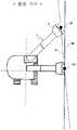
도 1은 본 발명의 제 1 실시예에 있어서의 유압 셔블의 외관도이다.
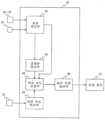
도 2는 본 발명의 제 1 실시예에 있어서의 컨트롤러의 기능 블록도이다.
도 3은 본 발명의 제 1 실시예에 있어서의 컨트롤러의 처리를 나타내는 플로우차트이다.
도 4는 종래 기술에 있어서의 침입 불가 영역 설정시의 작업 기계의 동작(그 1)을 나타내는 도면이다.
도 5는 종래 기술에 있어서의 침입 불가 영역 설정시의 작업 기계의 동작(그 2)을 나타내는 도면이다.
도 6은 본 발명의 제 1 실시예에 있어서의 침입 불가 영역 설정시의 작업 기계의 동작을 나타내는 도면이다.
도 7은 본 발명의 제 2 실시예에 있어서의 컨트롤러의 기능 블록도이다.
도 8은 본 발명의 제 2 실시예에 있어서의 컨트롤러의 처리를 나타내는 플로우차트이다.
도 9는 본 발명의 제 2 실시예에 있어서의 침입 불가 영역 설정시의 작업 기계의 동작을 나타내는 도면이다.
도 10은 본 발명의 제 3 실시예에 있어서의 컨트롤러의 처리를 나타내는 플로우차트이다.1 is an external view of a hydraulic excavator in a first embodiment of the present invention.
Fig. 2 is a functional block diagram of a controller in the first embodiment of the present invention.
Fig. 3 is a flowchart showing the processing of the controller in the first embodiment of the present invention.
Fig. 4 is a diagram showing an operation (part 1) of a work machine at the time of setting a non-intrusion area in the prior art.
Fig. 5 is a diagram showing the operation (part 2) of the work machine at the time of setting an intrusion-free area in the prior art.
Fig. 6 is a diagram showing the operation of the work machine at the time of setting the non-intrusion area in the first embodiment of the present invention.
7 is a functional block diagram of a controller in the second embodiment of the present invention.
Fig. 8 is a flowchart showing the processing of the controller in the second embodiment of the present invention.
Fig. 9 is a diagram showing the operation of the work machine at the time of setting the non-intrusion area in the second embodiment of the present invention.
Fig. 10 is a flowchart showing the processing of the controller in the third embodiment of the present invention.
이하, 본 발명의 실시 형태에 관련된 작업 기계로서 유압 셔블을 예로 들어, 도면을 참조하여 설명한다. 또한, 각 도면 중, 동등한 부재에는 동일한 부호를 붙이고, 중복되는 설명은 적절히 생략한다.EMBODIMENT OF THE INVENTION Hereinafter, a hydraulic excavator is taken as an example as a working machine concerning embodiment of this invention, and it demonstrates with reference to drawings. In addition, in each figure, the same code|symbol is attached|subjected to the equivalent member, and overlapping description is abbreviate|omitted suitably.
실시예 1Example 1
도 1은 본 발명의 제 1 실시예에 관련된 유압 셔블의 외관도이다. 도 1에 있어서, 유압 셔블(100)은, 하부 주행체(1)와, 하부 주행체(1) 상에 선회 가능하게 탑재된 상부 선회체(2)와, 상부 선회체(2)의 전측(前側)에 상하 방향으로 회동 가능하게 장착된 작업 장치(3)를 구비하고 있다. 하부 주행체(1)는 좌우의 주행 모터(4)(좌측만 도시)에 의해서 구동되고, 상부 선회체(2)는 선회 모터(5)에 의해서 구동된다.1 is an external view of a hydraulic excavator according to a first embodiment of the present invention. 1, the
작업 장치(3)는, 상부 선회체(2)의 전부(前部)에 상하 방향으로 회동 가능하게 장착된 붐(6)과, 붐(6)의 선단(先端)부에 상하, 전후 방향으로 회동 가능하게 장착된 암(7)과, 암(7)의 선단부에 상하, 전후 방향으로 회동 가능하게 장착된 버킷(8)을 갖는다. 붐(6)은 붐 실린더(9)에 의해서 구동되고, 암(7)은 암 실린더(10)에 의해서 구동되고, 버킷(8)은 버킷 실린더(11)에 의해서 구동된다. 버킷 실린더(11)의 선단은, 버킷 링크(12)를 개재하여 암(7) 및 버킷(8)에 회동 가능하게 지지되어 있다.The
상부 선회체(2)에는, 액추에이터(4, 5, 9∼11)를 구동하는 유압 장치(13)가 탑재되어 있다. 유압 장치(13)는, 원동기와, 원동기에 의해서 구동되는 유압 펌프, 유압 펌프로부터 액추에이터(4, 5, 9∼11)로 공급되는 압유의 유량을 제어하는 컨트롤 밸브 등에 의해 구성된다. 상부 선회체(2)의 전부 좌측에는, 오퍼레이터가 탑승하는 운전실(14)이 마련되어 있다.A
하부 주행체(1)와 상부 선회체(2)와의 사이에 마련된 센터 조인트(15)에는, 하부 주행체(1)에 대한 상부 선회체(2)의 상대 각도(선회 각도)를 검출하는 각도 센서(21)가 내장되어 있다. 붐(6), 암(7), 및 버킷 링크(12)에는 IMU 센서(22∼24)가 각각 장착되어 있다. IMU 센서(22∼24)는, 붐(6), 암(7), 및 버킷 링크(12)의 각속도로부터 붐(6), 암(7), 및 버킷(8)의 각도(작업 장치(3)의 자세)를 계측할 수 있다.In the
운전실(14)에는, 상부 선회체(2) 및 작업 장치(3)의 동작을 지시하기 위한 조작 장치(31), 각종 설정(침입 불가 영역 설정, 기타 차체 설정)이나 시계(視界) 보조에 이용하는 모니터(32), 차체 제어 및 영역 제한 관련 제어를 행하는 컨트롤러(40)(도 2에 나타냄)가 마련되어 있다. 모니터(32)는 터치 패널을 갖고 있고, 오퍼레이터는, 모니터(32)에 표시되는 버튼이나 스위치를 조작함으로써 각종 설정을 행할 수 있다. 모니터(32)에 표시되는 스위치에는, 버킷(8)의 위치 결정이 종료된 것을 컨트롤러(40)에 통지하기 위한 설정 스위치(33)(도 2에 나타냄)와, 버킷(8) 상에 미리 설정된 복수의 기준점 중에서 침입 불가 영역을 설정할 때에 사용하는 기준점을 선택하기 위한 선택 스위치(34)(도 2에 나타냄)가 포함된다.In the
도 2는 컨트롤러(40)의 기능 블록도이다. 도 2에 있어서, 컨트롤러(40)는 좌표 연산부(41)와 기준점 선택부(42)와 경계면 연산부(43)와 목표 속도 연산부(44)와 목표 속도 보정부(45)와 동작 지령 생성부(46)를 갖는다.2 is a functional block diagram of the
좌표 연산부(41)는, 선회 각도 및 작업 장치(3)의 자세에 기초하여, 작업 장치(3) 상에 미리 설정된 기준점의 좌표를 산출하고, 기준점 선택부(42)에 출력한다. 여기에서 말하는 기준점은, 작업 장치(3) 상 중 장해물이나 시공 대상물에 가장 접근할 가능성이 있는 1개 또는 복수의 위치에 설정된다. 또, 좌표 연산부(41)는, 설정 스위치(33)가 조작되었을 때의 버킷(8) 상의 기준점의 좌표를 산출하고, 기준점 선택부(42)에 출력한다. 본 실시예에서는, 버킷 갈고리 끝 좌단(左端) 위치(8L)에 제 1 기준점을 설정하고, 버킷 갈고리 끝 우단(右端) 위치(8R)에 제 2 기준점을 설정하지만, 기준점의 수 및 위치는 이것에 한정되지 않는다.The
기준점 선택부(42)는, 선택 스위치(34)의 조작에 따라서, 제 1 기준점 또는 제 2 기준점의 좌표를, 침입 불가 영역의 경계면 상의 점(제 1 지정점 또는 제 2 지정점)으로서 설정하고, 경계면 연산부(43)에 출력한다.The
경계면 연산부(43)는, 제 1 지정점과 제 2 지정점을 지나고, 또한 하부 주행체(1)의 접지면에 수직인 평면(이하, 수직면)을 침입 불가 영역의 경계면으로서 설정하고, 목표 속도 보정부(45)에 출력한다.The boundary
목표 속도 연산부(44)는, 조작 장치(31)로부터 입력되는 조작량에 기초하여 액추에이터(4, 5, 9∼11)의 목표 속도를 연산하고, 목표 속도 보정부(45)에 출력한다.The target
목표 속도 보정부(45)는, 작업 장치(3) 상에 미리 설정된 기준점이 침입 불가 영역의 경계면의 앞으로 이동하지 않도록 액추에이터(4, 5, 9∼11)의 목표 속도를 보정하고, 동작 지령 생성부(46)에 출력한다.The target
동작 지령 생성부(46)는, 액추에이터(4, 5, 9∼11)의 목표 속도에 따른 동작 지령을 생성하고, 유압 장치(13)에 출력한다. 이에 의해, 작업 장치(3)가 침입 불가 영역으로 침입하지 않도록 액추에이터(4, 5, 9∼11)가 구동된다.The operation
도 3은 컨트롤러(40)의 처리를 나타내는 플로우차트이다. 이하, 각 단계를 순서대로 설명한다.3 is a flowchart showing the processing of the
컨트롤러(40)는, 먼저, 설정 스위치(33)가 조작되었는지 여부를 판정한다(단계 S101). 단계 S101의 판정 결과가 NO인 경우는, 단계 S101로 되돌아간다.The
단계 S101의 판정 결과가 YES인 경우는, 이 때의 버킷(8)의 위치를 제 1 위치로 설정함과 함께, 선택 스위치(34)를 통하여, 버킷 갈고리 끝 좌단 위치(8L)(제 1 기준점) 및 버킷 갈고리 끝 우단 위치(8R)(제 2 기준점) 중 어느 것이 선택되었는지를 판정한다(단계 S102). 버킷 갈고리 끝 좌단 위치(8L)가 선택된 경우는, 버킷 갈고리 끝 좌단 위치(8L)를 제 1 지정점으로 설정하고(단계 S103), 버킷 갈고리 끝 우단 위치(8R)가 선택된 경우는, 버킷 갈고리 끝 우단 위치(8R)를 제 1 지정점으로 설정한다(단계 S104).When the determination result of step S101 is YES, the position of the
단계 S103 또는 단계 S104에 이어서, 설정 스위치(33)가 다시 조작되었는지 여부를 판정한다(단계 S105). 단계 S105의 판정 결과가 NO인 경우는, 단계 S105로 되돌아간다.Following step S103 or step S104, it is determined whether or not the setting
단계 S105의 판정 결과가 YES인 경우는, 이 때의 버킷(8)의 위치를 제 2 위치로 설정함과 함께, 선택 스위치(34)를 통하여, 버킷 갈고리 끝 좌단 위치(8L) 및 버킷 갈고리 끝 우단 위치(8R) 중 어느 것이 선택되었는지를 판정한다(단계 S106). 버킷 갈고리 끝 좌단 위치(8L)가 선택된 경우는, 버킷 갈고리 끝 좌단 위치(8L)를 제 2 지정점으로 설정하고(단계 S107), 버킷 갈고리 끝 우단 위치(8R)가 선택된 경우는, 버킷 갈고리 끝 우단 위치(8R)를 제 2 지정점으로 설정한다(단계 S108).When the determination result of step S105 is YES, the position of the
단계 S107 또는 단계 S108에 이어서, 제 1 지정점과 제 2 지정점을 지나는 수직면을 침입 불가 영역의 경계면으로서 산출하고(단계 S109), 당해 플로우를 종료한다.Following step S107 or step S108, the vertical plane passing through the first designation point and the second designation point is calculated as the interface of the non-invading area (step S109), and the flow ends.
여기에서, 종래 기술에 있어서의 침입 불가 영역의 설정 방법의 과제에 대하여, 도 4 및 도 5를 이용하여 설명한다. 또한, 본 실시예에서는, 작업 장치(3)가 구조물에 충돌하는 것을 방지하기 위하여, 당해 구조물의 벽면으로부터 앞의 영역을 침입 불가 영역으로서 설정하는 경우를 설명한다.Here, the problem of the method of setting the non-intrusion area in the prior art will be described using FIGS. 4 and 5 . In addition, in this embodiment, in order to prevent the
도 4 및 도 5에 나타내는 예에서는, 버킷 갈고리 끝 중앙 위치(8C)에 미리 설정된 기준점에서 공간 상의 2점을 지정하고, 이들 2점을 지나는 수직면(70)을 침입 불가 영역의 경계면으로서 산출한다. 그러나, 상부 선회체(2)가 벽면(60)에 정면으로 대하고 있지 않은 경우는, 버킷 갈고리 끝 중앙 위치(8C)로 벽면(60) 상의 점을 지정할 수는 없다. 그 때문에, 도 4에 나타낸 것과 같이 벽면(60)으로부터 떨어진 위치에 경계면(70)이 설정되거나, 도 5에 나타낸 것과 같이 벽면(60)과 교차하도록 경계면(70)이 설정되어 버린다.In the example shown in FIGS. 4 and 5 , two points in space are designated from reference points set in advance at the center position of the tip of the
다음으로, 본 실시예에 있어서의 침입 불가 영역 설정시의 오퍼레이터의 조작 순서를 도 6을 이용하여 설명한다.Next, the operation procedure of the operator at the time of setting the non-intrusion area in this embodiment will be described with reference to FIG. 6 .
조작 1: 버킷(8)의 위치 결정을 행한다. 구체적으로는, 버킷 갈고리 끝 좌단 위치(8L) 또는 버킷 갈고리 끝 우단 위치(8R)를 벽면(60)에 접촉시킨다. 도 4에 나타내는 예에서는, 버킷 갈고리 끝 우단 위치(8R)(제 2 기준점)가 벽면(60) 상의 점(A)에 위치해 있다.Operation 1: Positioning of the
조작 2: 버킷(8)의 위치 결정이 종료되면, 선택 스위치(34)를 통하여, 벽면(60)에 접촉해 있는 버킷 갈고리 끝 우단 위치(8R)(제 2 기준점)를 선택하고, 설정 스위치(33)를 조작한다. 이에 의해, 이 때의 버킷(8)의 위치가 제 1 위치로 설정되고, 벽면(60) 상의 점(A)이 제 1 지정점으로 설정된다.Operation 2: When the positioning of the
조작 3: 다시 버킷(8)의 위치 결정을 행한다. 구체적으로는, 제 1 위치와 다른 위치에서, 버킷 갈고리 끝 좌단 위치(8L) 또는 버킷 갈고리 끝 우단 위치(8R)를 벽면(60)에 접촉시킨다. 도 6에 나타내는 예에서는, 버킷 갈고리 끝 좌단 위치(8L)(제 1 기준점)가 벽면(60) 상의 점(B)에 위치해 있다.Operation 3: Positioning of the
조작 4: 버킷(8)의 위치 결정이 종료되면, 선택 스위치(34)를 통하여, 벽면(60)에 접촉해 있는 버킷 갈고리 끝 우단 위치(8R)(제 1 기준점)를 선택하고, 설정 스위치(33)를 조작한다. 이에 의해, 이 때의 버킷(8)의 위치가 제 2 위치로 설정되고, 벽면(60) 상의 점(B)이 제 2 지정점으로 설정되고, 제 1 지정점(A)과 제 2 지정점(B)을 지나는 수직면(70)이 침입 불가 영역의 경계면으로서 산출된다.Operation 4: When the positioning of the
(정리)(organize)
본 실시예에서는, 하부 주행체(1)와, 하부 주행체(1) 상에 선회 가능하게 장착된 상부 선회체(2)와, 상부 선회체(2)에 상하 방향으로 회동 가능하게 장착된, 작업구(8)를 포함하는 작업 장치(3)와, 작업 장치(3)를 구동하는 복수의 액추에이터(4, 5, 9∼11)와, 작업 장치(3)가 주위에 설정된 침입 불가 영역에 침입하지 않도록 복수의 액추에이터(4, 5, 9∼11)의 동작을 제어하는 컨트롤러(40)를 구비한 작업 기계(100)에 있어서, 오퍼레이터 조작에 의해 상기 침입 불가 영역을 설정하는 설정 스위치(33)를 구비하며, 컨트롤러(40)는, 설정 스위치(33)가 조작되었을 때의 작업구(8)의 위치를 제 1 위치로서 설정하고, 상기 제 1 위치의 설정 후에 설정 스위치(33)가 조작되었을 때의 작업구(8)의 위치를 제 2 위치로서 설정하고, 작업구(8)가 상기 제 1 위치에 있을 때의 작업구(8)에 미리 설정된 복수의 기준점(8L, 8R) 중 1개의 기준점인 제 1 기준점(A)과, 작업구(8)가 상기 제 2 위치에 있을 때의 복수의 기준점(8L, 8R) 중 1개의 기준점인 제 2 기준점(B)을 지나고, 또한 하부 주행체(1)의 접지면에 수직인 평면(70)을 상기 침입 불가 영역의 경계면(70)으로서 설정한다.In this embodiment, the
이상과 같이 구성한 본 실시예에 의하면, 작업 장치(3)의 침입 불가 영역을 설정할 때에 사용하는 기준점을, 작업구(8) 상에 미리 설정된 복수의 기준점(8L, 8R) 중에서 선택할 수 있게 함으로써, 작업 장치(3)의 침입 불가 영역을 오퍼레이터의 의도에 들어맞게 유연하게 설정하는 것이 가능하게 된다.According to the present embodiment configured as described above, the reference point used when setting the non-intrusion area of the
또, 본 실시예에 있어서의 작업 기계(100)는, 복수의 기준점(8L, 8R) 중 어느 1개의 기준점을 선택하기 위한 선택 스위치(34)를 구비하고, 컨트롤러(40)는, 선택 스위치(34)의 조작에 따라서, 작업구(8)가 상기 제 1 위치에 있을 때에 복수의 기준점(8L, 8R)으로부터 제 1 기준점(A)을 선택하고, 작업구(8)가 상기 제 2 위치에 있을 때에 복수의 기준점(8L, 8R)으로부터 제 2 기준점(B)을 선택한다. 이에 의해, 작업구(8) 상의 복수의 기준점(8L, 8R) 중에서 침입 불가 영역의 설정에 사용하는 기준점을 오퍼레이터에게 선택시키는 것이 가능하게 된다.In addition, the
또, 본 실시예에 있어서의 작업구(8)는 버킷이며, 복수의 기준점(8L, 8R)은, 버킷(8)의 갈고리 끝 좌단에 위치하는 점(8L)과, 버킷(8)의 갈고리 끝 우단에 위치하는 점(8R)을 포함한다. 이에 의해, 버킷(8)을 구비한 작업 기계(100)에 있어서, 오퍼레이터의 의도에 들어맞는 침입 불가 영역을 유연하게 설정하는 것이 가능하게 된다.In addition, the
실시예 2Example 2
본 발명의 제 2 실시예에 대하여, 제 1 실시예와의 상위점을 중심으로 설명한다.The second embodiment of the present invention will be described focusing on differences from the first embodiment.
도 7은 본 실시예에 있어서의 컨트롤러(40)의 기능 블록도이다. 도 7에 있어서, 컨트롤러(40)는, 제 1 실시예에 있어서의 기준점 선택부(42)(도 2에 나타냄)를 갖고 있지 않다. 좌표 연산부(41)는, 설정 스위치(33)가 조작되었을 때의 버킷(8) 상의 기준점(8L, 8R)의 좌표를 산출하고, 경계면 연산부(43)에 출력한다.7 is a functional block diagram of the
도 8은 본 실시예에 있어서의 컨트롤러(40)의 처리를 나타내는 플로우차트이다. 이하, 각 단계를 순서대로 설명한다.8 is a flowchart showing the processing of the
컨트롤러(40)는, 먼저, 설정 스위치(33)가 조작되었는지 여부를 판정한다(단계 S201). 단계 S201의 판정 결과가 NO인 경우는, 단계 S201로 되돌아간다.The
단계 S201의 판정 결과가 YES인 경우는, 이 때의 버킷(8)의 위치를 제 1 위치로 설정하고, 버킷 갈고리 끝 좌단 위치(8L) 및 버킷 갈고리 끝 우단 위치(8R)를 각각 제 1 지정점으로 설정한다(단계 S202).If the determination result of step S201 is YES, the position of the
단계 S202에 이어서, 설정 스위치(33)가 다시 조작되는지 여부를 판정한다(단계 S203). 단계 S203의 판정 결과가 NO인 경우는, 단계 S202로 되돌아간다.Following step S202, it is determined whether or not the setting
단계 S203의 판정 결과가 YES인 경우는, 이 때의 버킷(8)의 위치를 제 2 위치로 설정하고, 버킷 갈고리 끝 좌단 위치(8L) 및 버킷 갈고리 끝 우단 위치(8R)를 각각 제 2 지정점으로 설정한다(단계 S204).If the determination result of step S203 is YES, the position of the
단계 S204에 이어서, 제 1 지정점과 제 2 지정점을 지나는 모든 수직면을 산출한다(단계 S205).Following step S204, all vertical planes passing through the first and second designation points are calculated (step S205).
단계 S205에 이어서, 단계 S205에서 산출한 복수의 수직면 중 선회 중심으로부터의 거리가 가장 큰 수직면을 침입 불가 영역의 경계면으로 설정하고(단계 S206), 당해 플로우를 종료한다. 또한, 본 실시예에서는, 제 1 지정점과 제 2 지정점을 지나는 모든 수직면을 산출하고 있지만, 어느 수직면이 선회 중심으로부터의 거리가 가장 커지는지는 제 1 지정점과 제 2 지정점과의 위치 관계로부터 판별할 수 있기 때문에, 반드시 모든 수직면을 산출하지 않아도 된다.Following step S205, the vertical plane with the largest distance from the pivot center among the plurality of vertical planes calculated in step S205 is set as the boundary plane of the non-invading region (step S206), and the flow ends. Further, in this embodiment, all vertical planes passing through the first and second designation points are calculated, but which vertical plane has the largest distance from the turning center can be determined from the positional relationship between the first and second designation points. Since there is, it is not necessary to calculate all vertical planes.
본 실시예에 있어서의 침입 불가 영역 설정시의 오퍼레이터의 조작 순서를 도 9를 이용하여 설명한다.An operator's operating procedure at the time of setting an intrusion-prone area in this embodiment will be described with reference to FIG. 9 .
조작 1: 버킷(8)의 위치 결정을 행한다. 구체적으로는, 버킷 갈고리 끝 좌단 위치(8L) 또는 버킷 갈고리 끝 우단 위치(8R)를 벽면(60)에 접촉시킨다. 도 9에 나타내는 예에서는, 버킷 갈고리 끝 우단 위치(8R)가 벽면(60) 상의 점(A)에 위치해 있다.Operation 1: Positioning of the
조작 2: 설정 스위치(33)를 조작한다. 이 때의 버킷(8)의 위치가 제 1 위치로 설정된다.Operation 2: Operate the setting
조작 3: 다시 버킷(8)의 위치 결정을 행한다. 구체적으로는, 제 1 위치와 다른 위치에서, 버킷 갈고리 끝 좌단 위치(8L) 또는 버킷 갈고리 끝 우단 위치(8R)를 벽면(60)에 접촉시킨다. 도 9에 나타내는 예에서는, 버킷 갈고리 끝 좌단 위치(8L)가 벽면(60) 상의 점(B)에 위치해 있다.Operation 3: Positioning of the
조작 4: 설정 스위치(33)를 조작한다. 이 때의 버킷(8)의 위치가 제 2 위치로 설정된다. 이에 의해, 버킷(8)이 제 1 위치에 있을 때의 2개의 기준점(8L, 8R)(제 1 지정점) 중 1개와 버킷(8)이 제 2 위치에 있을 때의 2개의 기준점(8L, 8R)(제 2 지정점) 중 1개를 지나는 4개의 수직면(70∼73)이 산출되고, 이들 4개의 수직면(70∼73) 중 선회 중심으로부터의 거리가 가장 큰 수직면(70)이 침입 불가 영역의 경계면으로서 설정된다.Operation 4: Operate the setting
(정리)(organize)
본 실시예에 있어서의 제 1 기준점 및 제 2 기준점은, 작업구(8)가 제 1 위치에 있을 때의 복수의 기준점(8L, 8R)의 각각의 기준점과, 작업구(8)가 제 2 위치에 있을 때의 복수의 기준점(8L, 8R)의 각각의 기준점을 접지면에 수직인 상태에서 지나는 복수의 평면(70∼73) 중, 상부 선회체(2)의 선회 중심으로부터의 거리가 가장 큰 평면(70) 상에 위치하는 기준점이다.The first reference point and the second reference point in this embodiment are each of the plurality of
또, 본 실시예에 있어서의 컨트롤러(40)는, 작업구(8)가 제 1 위치에 있을 때의 복수의 기준점(8L, 8R)의 각각의 기준점과, 작업구(8)가 제 2 위치에 있을 때의 복수의 기준점(8L, 8R)의 각각의 기준점을 지나고, 또한 하부 주행체(1)의 접지면에 수직이 되는 평면(70∼73)을 복수 산출하고, 산출된 평면(70∼73) 중 상부 선회체(2)의 선회 중심으로부터의 거리가 가장 큰 평면(70)을 침입 불가 영역의 경계면으로 설정한다.In addition, the
이상과 같이 구성한 본 실시예에 있어서도, 제 1 실시예와 마찬가지로, 오퍼레이터의 의도에 들어맞는 침입 불가 영역을 유연하게 설정하는 것이 가능하게 된다. 또한, 오퍼레이터는, 제 1 지정점과 제 2 지정점을 설정할 때에 작업구(8) 상의 기준점을 선택할 필요가 없기 때문에, 제 1 실시예보다 간편하게 침입 불가 영역을 설정할 수 있다.Also in this embodiment structured as described above, as in the first embodiment, it is possible to flexibly set an intrusion-prone area that matches the operator's intention. In addition, since the operator does not need to select a reference point on the
실시예 3Example 3
본 발명의 제 3 실시예에 대하여, 제 2 실시예와의 상위점을 중심으로 설명한다.The third embodiment of the present invention will be described focusing on differences from the second embodiment.
제 1 실시예 또는 제 2 실시예에서는, 제 1 지정점을 설정하고 나서 제 2 지정점을 설정할 때까지의 동안에 하부 주행체(1)가 이동한 경우, 제 1 지정점의 좌표를 산출할 때의 좌표축과 제 2 지정점을 산출할 때의 좌표축이 일치하지 않게 되기 때문에, 오퍼레이터가 의도하지 않는 경계면이 설정될 우려가 있다. 본 실시예는 이 문제를 해결하는 것이다.In the first or second embodiment, when the
도 10은 본 실시예에 있어서의 컨트롤러(40)의 처리를 나타내는 플로우차트이다. 본 실시예에서는, 단계 S202를 실시한 후에, 주행 조작이 행해졌는지 여부를 판정한다(단계 S202A). 단계 S202A의 판정 결과가 YES인 경우는 단계 S201로 되돌아가고, 판정 결과가 NO인 경우는 단계 S203으로 이행한다. 이에 의해, 작업구(8)의 제 1 위치가 설정되고 나서 작업구(8)의 제 2 위치가 설정될 때까지의 동안에 하부 주행체(1)가 주행한 경우에는, 제 1 위치의 설정이 리셋 되기 때문에, 제 1 지정점을 산출하였을 때의 좌표계와 다른 좌표계에서 제 2 지정점이 산출되는 것을 방지할 수 있다.Fig. 10 is a flowchart showing the processing of the
(정리)(organize)
본 실시예에 있어서의 컨트롤러(40)는, 작업구(8)의 제 1 위치가 설정되고 나서 작업구(8)의 제 2 위치가 설정될 때까지의 동안에 하부 주행체(1)가 주행한 경우에는, 상기 제 1 위치의 설정을 리셋 한다.The
이상과 같이 구성한 본 실시예에 의하면, 제 1 지정점을 산출하였을 때의 좌표계와 다른 좌표계에서 제 2 지정점이 산출되는 것을 방지할 수 있기 때문에, 부정확한 침입 불가 영역이 설정되는 것을 방지하는 것이 가능하게 된다.According to the present embodiment configured as described above, since it is possible to prevent the second specified point from being calculated in a coordinate system different from the coordinate system used when the first specified point was calculated, it is possible to prevent an inaccurate no-intrusion area from being set. do.
이상, 본 발명의 실시예에 대하여 상술하였지만, 본 발명은 상기한 실시예에 한정되는 것은 아니며, 여러 가지 변형례가 포함된다. 예를 들면, 상기한 실시예는, 본 발명을 이해하기 쉽게 설명하기 위하여 상세하게 설명한 것이며, 반드시 설명한 모든 구성을 구비하는 것에 한정되는 것은 아니다. 또, 어떤 실시예의 구성에 다른 실시예의 구성의 일부를 추가하는 것도 가능하고, 어떤 실시예의 구성의 일부를 삭제하고, 또는, 다른 실시예의 일부와 치환하는 것도 가능하다.In the above, although the embodiment of the present invention has been described above, the present invention is not limited to the above embodiment, and various modifications are included. For example, the above embodiments have been described in detail in order to easily understand the present invention, and are not necessarily limited to those having all the described configurations. In addition, it is possible to add a part of the structure of another embodiment to the structure of a certain embodiment, delete a part of the structure of a certain embodiment, or replace it with a part of the structure of another embodiment.
1 … 하부 주행체, 2 … 상부 선회체, 3 … 작업 장치, 4 … 주행 모터(액추에이터), 5 … 선회 모터(액추에이터), 6 … 붐, 7 … 암, 8 … 버킷(작업구), 9 … 붐 실린더(액추에이터), 10 … 암 실린더(액추에이터), 11 … 버킷 실린더(액추에이터), 12 … 버킷 링크, 13 … 유압 장치, 14 … 운전실, 15 … 센터 조인트, 21 … 각도 센서, 22∼24 … IMU 센서, 31 … 조작 장치, 32 … 모니터, 33 … 설정 스위치, 34 … 선택 스위치, 40 … 컨트롤러, 41 … 좌표 연산부, 42 … 기준점 선택부, 43 … 경계면 연산부, 44 … 목표 속도 연산부, 45 … 목표 속도 보정부, 46 … 동작 지령 생성부, 60 … 벽면, 70 … 수직면(경계면), 71∼73 … 수직면, 100 … 유압 셔블(작업 기계).One … lower traveling body, 2 . . . Upper swing body, 3 . . . working device, 4 . . . travel motor (actuator), 5 … Swing motor (actuator), 6 … Boom, 7... cancer, 8 … Bucket (work tool), 9 . . . Boom cylinder (actuator), 10 … Arm cylinder (actuator), 11 … Bucket cylinder (actuator), 12 … bucket link, 13 . . . hydraulic system, 14 … cab, 15 … center joint, 21 . . . Angle sensor, 22 to 24 . . . IMU sensor, 31 . . . operating device, 32... monitor, 33 . . . setting switch, 34 … selection switch, 40 … controller, 41 . . . Coordinate calculation unit, 42 . . . Reference point selection unit, 43 . . . Boundary calculation unit, 44 . . . target speed calculation unit, 45 . . . Target speed correction unit, 46 . . . operation command generator, 60 . . . wall, 70 … Vertical plane (boundary plane), 71 to 73... vertical plane, 100... Hydraulic shovel (working machine).
Claims (6)
Translated fromKorean상기 하부 주행체 상에 선회 가능하게 장착된 상부 선회체와,
상기 상부 선회체에 상하 방향으로 회동 가능하게 장착된, 작업구를 포함하는 작업 장치와,
상기 작업 장치를 구동하는 복수의 액추에이터와,
상기 작업 장치가 주위에 설정된 침입 불가 영역에 침입하지 않도록 상기 복수의 액추에이터의 동작을 제어하는 컨트롤러를 구비한 작업 기계에 있어서,
오퍼레이터 조작에 의해 상기 침입 불가 영역을 설정하는 설정 스위치를 구비하며,
상기 컨트롤러는,
상기 설정 스위치가 조작되었을 때의 상기 작업구의 위치를 제 1 위치로서 설정하고,
상기 제 1 위치의 설정 후에 상기 설정 스위치가 조작되었을 때의 상기 작업구의 위치를 제 2 위치로서 설정하고,
상기 작업구가 상기 제 1 위치에 있을 때의 상기 작업구에 미리 설정된 복수의 기준점 중 1개의 기준점인 제 1 기준점과, 상기 작업구가 상기 제 2 위치에 있을 때의 상기 복수의 기준점 중 1개의 기준점인 제 2 기준점을 지나고, 또한 상기 하부 주행체의 접지면에 수직인 평면을 상기 침입 불가 영역의 경계면으로서 설정하는
것을 특징으로 하는 작업 기계.a lower driving body;
An upper swing body rotatably mounted on the lower traveling body;
A working device including a working tool mounted to the upper swing body so as to be rotatable in the vertical direction;
a plurality of actuators that drive the work device;
In the work machine provided with a controller that controls the operation of the plurality of actuators so that the work device does not intrude into an inaccessible area set around it,
A setting switch for setting the non-intrusion area by operator manipulation;
The controller,
A position of the work tool when the setting switch is operated is set as a first position;
After setting the first position, the position of the work tool when the setting switch is operated is set as a second position,
A first reference point, which is one reference point among a plurality of reference points preset on the work tool when the work tool is in the first position, and one of the plurality of reference points when the work tool is in the second position Setting a plane passing through a second reference point that is a reference point and perpendicular to the ground plane of the undercarriage as the boundary of the intrusion-prone area
Working machine, characterized in that.
상기 복수의 기준점 중 어느 1개의 기준점을 선택하기 위한 선택 스위치를 구비하며,
상기 컨트롤러는, 상기 선택 스위치의 조작에 따라서, 상기 작업구가 상기 제 1 위치에 있을 때에 상기 복수의 기준점으로부터 상기 제 1 기준점을 선택하고, 상기 작업구가 상기 제 2 위치에 있을 때에 상기 복수의 기준점으로부터 상기 제 2 기준점을 선택하는
것을 특징으로 하는 작업 기계.According to claim 1,
A selection switch for selecting any one reference point among the plurality of reference points,
The controller selects the first reference point from the plurality of reference points when the work tool is at the first position in accordance with the operation of the selection switch, and selects the first reference point from the plurality of reference points when the work tool is at the second position. Selecting the second reference point from the reference point
Working machine, characterized in that.
상기 제 1 기준점 및 상기 제 2 기준점은, 상기 작업구가 상기 제 1 위치에 있을 때의 상기 복수의 기준점의 각각의 기준점과, 상기 작업구가 상기 제 2 위치에 있을 때의 상기 복수의 기준점의 각각의 기준점을 상기 접지면에 수직인 상태에서 지나는 복수의 평면 중, 상기 상부 선회체의 선회 중심으로부터의 거리가 가장 큰 평면 상에 위치하는 기준점인
것을 특징으로 하는 작업 기계.According to claim 1,
The first reference point and the second reference point are the respective reference points of the plurality of reference points when the work tool is in the first position and the plurality of reference points when the work tool is in the second position. Among a plurality of planes passing each reference point in a state perpendicular to the ground plane, a reference point located on a plane having the largest distance from the turning center of the upper swing body.
Working machine, characterized in that.
상기 컨트롤러는,
상기 작업구가 상기 제 1 위치에 있을 때의 상기 복수의 기준점의 각각의 기준점과, 상기 작업구가 상기 제 2 위치에 있을 때의 상기 복수의 기준점의 각각의 기준점을 지나고, 또한 상기 접지면에 수직이 되는 평면을 복수 산출하고,
산출된 상기 평면 중 상기 상부 선회체의 선회 중심으로부터의 거리가 가장 큰 평면을 상기 침입 불가 영역의 상기 경계면으로 설정하는
것을 특징으로 하는 작업 기계.According to claim 1,
The controller,
Passing each reference point of the plurality of reference points when the work tool is in the first position and each reference point of the plurality of reference points when the work tool is in the second position, and also to the ground plane Calculate a plurality of vertical planes,
Setting the plane with the largest distance from the turning center of the upper swing body among the calculated planes as the boundary surface of the intrusion-prone area
Working machine, characterized in that.
상기 작업구는 버킷이며,
상기 복수의 기준점은, 상기 버킷의 갈고리 끝 좌단에 위치하는 점과, 상기 버킷의 갈고리 끝 우단에 위치하는 점을 포함하는
것을 특징으로 하는 작업 기계.According to claim 1,
The work tool is a bucket,
The plurality of reference points include a point located at the left end of the hook end of the bucket and a point located at the right end of the hook end of the bucket.
Working machine, characterized in that.
상기 컨트롤러는, 상기 제 1 위치가 설정되고 나서 상기 제 2 위치가 설정될 때까지의 동안에 상기 하부 주행체가 주행한 경우에는, 상기 제 1 위치의 설정을 리셋 하는
것을 특징으로 하는 작업 기계.According to claim 1,
The controller resets the setting of the first position when the undercarriage travels between the setting of the first position and the setting of the second position.
Working machine, characterized in that.
Applications Claiming Priority (3)
| Application Number | Priority Date | Filing Date | Title |
|---|---|---|---|
| JP2021047789 | 2021-03-22 | ||
| JPJP-P-2021-047789 | 2021-03-22 | ||
| PCT/JP2021/041437WO2022201623A1 (en) | 2021-03-22 | 2021-11-11 | Work machine |
Publications (2)
| Publication Number | Publication Date |
|---|---|
| KR20230043172Atrue KR20230043172A (en) | 2023-03-30 |
| KR102698842B1 KR102698842B1 (en) | 2024-08-27 |
Family
ID=83395320
Family Applications (1)
| Application Number | Title | Priority Date | Filing Date |
|---|---|---|---|
| KR1020237006329AActiveKR102698842B1 (en) | 2021-03-22 | 2021-11-11 | work machine |
Country Status (6)
| Country | Link |
|---|---|
| US (1) | US12297620B2 (en) |
| EP (1) | EP4187022A4 (en) |
| JP (1) | JP7332836B2 (en) |
| KR (1) | KR102698842B1 (en) |
| CN (1) | CN115917090B (en) |
| WO (1) | WO2022201623A1 (en) |
Cited By (2)
| Publication number | Priority date | Publication date | Assignee | Title |
|---|---|---|---|---|
| WO2024135970A1 (en) | 2022-12-23 | 2024-06-27 | 주식회사 엘지에너지솔루션 | Battery pack and vehicle comprising same |
| WO2025005310A1 (en)* | 2023-06-26 | 2025-01-02 | 볼보 컨스트럭션 이큅먼트 에이비 | Construction machine |
Families Citing this family (1)
| Publication number | Priority date | Publication date | Assignee | Title |
|---|---|---|---|---|
| WO2021010489A1 (en)* | 2019-07-17 | 2021-01-21 | 住友建機株式会社 | Work machine and assistance device that assists work using work machine |
Citations (6)
| Publication number | Priority date | Publication date | Assignee | Title |
|---|---|---|---|---|
| KR0127860B1 (en)* | 1993-12-11 | 1998-04-08 | 김형벽 | Excavator's working range limiter |
| JP2009228249A (en)* | 2008-03-21 | 2009-10-08 | Caterpillar Japan Ltd | Interference prevention device for working machine |
| JP2015055109A (en)* | 2013-09-12 | 2015-03-23 | 日立建機株式会社 | Device and method for computing basic information for excavation region restriction control, and construction machine |
| WO2020012609A1 (en) | 2018-07-12 | 2020-01-16 | 日立建機株式会社 | Work machine |
| JP2020041388A (en)* | 2018-09-14 | 2020-03-19 | 日立建機株式会社 | Work machine |
| JP2020143449A (en)* | 2019-03-04 | 2020-09-10 | 日立建機株式会社 | Work machine |
Family Cites Families (11)
| Publication number | Priority date | Publication date | Assignee | Title |
|---|---|---|---|---|
| JP3679848B2 (en)* | 1995-12-27 | 2005-08-03 | 日立建機株式会社 | Construction machine working range restriction control device |
| JP4467694B2 (en)* | 1999-12-28 | 2010-05-26 | 株式会社加藤製作所 | Hydraulic excavator with crane function |
| US8457828B2 (en)* | 2005-06-27 | 2013-06-04 | The Charles Machine Works, Inc. | Remote control machine with partial or total autonomous control |
| JP2011084911A (en)* | 2009-10-14 | 2011-04-28 | Kobelco Contstruction Machinery Ltd | Work attachment control device of construction machine and method of controlling work attachment |
| DE112013000165B4 (en)* | 2013-04-12 | 2019-02-07 | Komatsu Ltd. | Control system for a construction machine and control method |
| JP2016223088A (en)* | 2015-05-28 | 2016-12-28 | 日立建機株式会社 | Construction machine |
| SE539699C2 (en)* | 2016-04-21 | 2017-10-31 | Construction Tools Pc Ab | Safety system, method and computer program for remotely controlled work vehicles |
| JP6714534B2 (en)* | 2017-03-29 | 2020-06-24 | 日立建機株式会社 | Construction machinery |
| CN107795538B (en)* | 2017-12-01 | 2023-09-08 | 江苏徐工工程机械研究院有限公司 | Travel motor shift valve, travel motor and construction machinery |
| WO2019144686A1 (en)* | 2018-01-26 | 2019-08-01 | Guangxi Liugong Machinery Co., Ltd. | Loader with lifting arrangement |
| KR102659075B1 (en)* | 2018-03-26 | 2024-04-18 | 스미토모 겐키 가부시키가이샤 | shovel |
- 2021
- 2021-11-11WOPCT/JP2021/041437patent/WO2022201623A1/ennot_activeCeased
- 2021-11-11JPJP2023508449Apatent/JP7332836B2/enactiveActive
- 2021-11-11CNCN202180052793.XApatent/CN115917090B/enactiveActive
- 2021-11-11USUS18/022,366patent/US12297620B2/enactiveActive
- 2021-11-11KRKR1020237006329Apatent/KR102698842B1/enactiveActive
- 2021-11-11EPEP21933221.0Apatent/EP4187022A4/enactivePending
Patent Citations (6)
| Publication number | Priority date | Publication date | Assignee | Title |
|---|---|---|---|---|
| KR0127860B1 (en)* | 1993-12-11 | 1998-04-08 | 김형벽 | Excavator's working range limiter |
| JP2009228249A (en)* | 2008-03-21 | 2009-10-08 | Caterpillar Japan Ltd | Interference prevention device for working machine |
| JP2015055109A (en)* | 2013-09-12 | 2015-03-23 | 日立建機株式会社 | Device and method for computing basic information for excavation region restriction control, and construction machine |
| WO2020012609A1 (en) | 2018-07-12 | 2020-01-16 | 日立建機株式会社 | Work machine |
| JP2020041388A (en)* | 2018-09-14 | 2020-03-19 | 日立建機株式会社 | Work machine |
| JP2020143449A (en)* | 2019-03-04 | 2020-09-10 | 日立建機株式会社 | Work machine |
Cited By (2)
| Publication number | Priority date | Publication date | Assignee | Title |
|---|---|---|---|---|
| WO2024135970A1 (en) | 2022-12-23 | 2024-06-27 | 주식회사 엘지에너지솔루션 | Battery pack and vehicle comprising same |
| WO2025005310A1 (en)* | 2023-06-26 | 2025-01-02 | 볼보 컨스트럭션 이큅먼트 에이비 | Construction machine |
Also Published As
| Publication number | Publication date |
|---|---|
| CN115917090A (en) | 2023-04-04 |
| EP4187022A4 (en) | 2024-11-06 |
| US12297620B2 (en) | 2025-05-13 |
| CN115917090B (en) | 2025-06-06 |
| EP4187022A1 (en) | 2023-05-31 |
| JP7332836B2 (en) | 2023-08-23 |
| US20230366171A1 (en) | 2023-11-16 |
| WO2022201623A1 (en) | 2022-09-29 |
| JPWO2022201623A1 (en) | 2022-09-29 |
| KR102698842B1 (en) | 2024-08-27 |
Similar Documents
| Publication | Publication Date | Title |
|---|---|---|
| KR20230043172A (en) | work machine | |
| JP3215502B2 (en) | Work machine operation range limiting device | |
| CN108699802B (en) | Working machine | |
| KR101755362B1 (en) | Control system for work vehicle, control method and work vehicle | |
| KR101731368B1 (en) | Control system for work vehicle, control method, and work vehicle | |
| CN113508206B (en) | Construction machine | |
| JP6209276B2 (en) | Work machine control device, work machine, and work machine control method | |
| CN113557340A (en) | Working machine | |
| KR101812127B1 (en) | Control system for work vehicle, control method, and work vehicle | |
| JP6872945B2 (en) | Construction machinery | |
| WO2018003176A1 (en) | Work machine | |
| EP3719212B1 (en) | System for remapping a control signal for excavator arm movement to a rotatory degree of freedom of a tool | |
| US12227922B2 (en) | Work machine | |
| WO2020170687A1 (en) | Safety device and construction machine | |
| US20230407594A1 (en) | Route setting system | |
| WO2023100689A1 (en) | Construction machine driving device, and construction machine and construction machine system provided with same | |
| KR20210124442A (en) | working machine | |
| KR20190030759A (en) | Control method of working vehicle and working vehicle | |
| JP6871946B2 (en) | Work vehicle and control method of work vehicle | |
| US12338602B2 (en) | System for handling the seamless transition of breaklines during an excavation task | |
| JP7397235B2 (en) | working machine | |
| WO2023053584A1 (en) | Trajectory-generating system and work machine comprising same | |
| CN118647773A (en) | Work area setting system | |
| CN117980567A (en) | Track generation system and construction machine provided with same |
Legal Events
| Date | Code | Title | Description |
|---|---|---|---|
| PA0105 | International application | Patent event date:20230222 Patent event code:PA01051R01D Comment text:International Patent Application | |
| PA0201 | Request for examination | ||
| PG1501 | Laying open of application | ||
| E701 | Decision to grant or registration of patent right | ||
| PE0701 | Decision of registration | Patent event code:PE07011S01D Comment text:Decision to Grant Registration Patent event date:20240722 | |
| GRNT | Written decision to grant | ||
| PR0701 | Registration of establishment | Comment text:Registration of Establishment Patent event date:20240821 Patent event code:PR07011E01D | |
| PR1002 | Payment of registration fee | Payment date:20240822 End annual number:3 Start annual number:1 | |
| PG1601 | Publication of registration |