KR20230042427A - Rotary push bar cleaner - Google Patents
Rotary push bar cleanerDownload PDFInfo
- Publication number
- KR20230042427A KR20230042427AKR1020210125385AKR20210125385AKR20230042427AKR 20230042427 AKR20230042427 AKR 20230042427AKR 1020210125385 AKR1020210125385 AKR 1020210125385AKR 20210125385 AKR20210125385 AKR 20210125385AKR 20230042427 AKR20230042427 AKR 20230042427A
- Authority
- KR
- South Korea
- Prior art keywords
- mop
- mop plate
- cylindrical bar
- fastening
- bevel gear
- Prior art date
- Legal status (The legal status is an assumption and is not a legal conclusion. Google has not performed a legal analysis and makes no representation as to the accuracy of the status listed.)
- Ceased
Links
Images


Classifications
- A—HUMAN NECESSITIES
- A47—FURNITURE; DOMESTIC ARTICLES OR APPLIANCES; COFFEE MILLS; SPICE MILLS; SUCTION CLEANERS IN GENERAL
- A47L—DOMESTIC WASHING OR CLEANING; SUCTION CLEANERS IN GENERAL
- A47L13/00—Implements for cleaning floors, carpets, furniture, walls, or wall coverings
- A47L13/10—Scrubbing; Scouring; Cleaning; Polishing
- A47L13/20—Mops
- A47L13/24—Frames for mops; Mop heads
- A47L13/254—Plate frames
- A—HUMAN NECESSITIES
- A47—FURNITURE; DOMESTIC ARTICLES OR APPLIANCES; COFFEE MILLS; SPICE MILLS; SUCTION CLEANERS IN GENERAL
- A47L—DOMESTIC WASHING OR CLEANING; SUCTION CLEANERS IN GENERAL
- A47L13/00—Implements for cleaning floors, carpets, furniture, walls, or wall coverings
- A47L13/10—Scrubbing; Scouring; Cleaning; Polishing
- A47L13/11—Squeegees
- A—HUMAN NECESSITIES
- A47—FURNITURE; DOMESTIC ARTICLES OR APPLIANCES; COFFEE MILLS; SPICE MILLS; SUCTION CLEANERS IN GENERAL
- A47L—DOMESTIC WASHING OR CLEANING; SUCTION CLEANERS IN GENERAL
- A47L13/00—Implements for cleaning floors, carpets, furniture, walls, or wall coverings
- A47L13/10—Scrubbing; Scouring; Cleaning; Polishing
- A47L13/20—Mops
- A47L13/24—Frames for mops; Mop heads
- A47L13/254—Plate frames
- A47L13/256—Plate frames for mops made of cloth
- B—PERFORMING OPERATIONS; TRANSPORTING
- B25—HAND TOOLS; PORTABLE POWER-DRIVEN TOOLS; MANIPULATORS
- B25G—HANDLES FOR HAND IMPLEMENTS
- B25G3/00—Attaching handles to the implements
- B25G3/38—Hinged, pivoted, swivelling, or folding joints
Landscapes
- Engineering & Computer Science (AREA)
- Mechanical Engineering (AREA)
- Cleaning Implements For Floors, Carpets, Furniture, Walls, And The Like (AREA)
Abstract
Description
Translated fromKorean본 발명은 회전형 밀대 청소기에 관한 것으로서, 더욱 상세하게는 쓸어내는 비 용도와 닦아내는 걸레 용도의 두 가지 기능을 하나로 묶어 필요에 따라 선택 사용이 가능한 회전형 밀대 청소기에 관한 것이다.The present invention relates to a rotary push rod cleaner, and more particularly, to a rotary push rod cleaner that combines two functions, one for sweeping rain and one for wiping mop, and which can be selectively used as needed.
일반적으로 밀대 청소기는 사용자가 서서 지저분한 바닥을 청소하거나 벽면에 면지를 닦아 내기 위한 것으로, 길이 방향의 밀대 끝단부에 여러 종류의 걸레를 체결 또는 연결하여 사용할 수 있도록 된 청소용 도구이다.In general, a rolling pin cleaner is a cleaning tool for a user to stand and clean a dirty floor or wipe cotton paper on a wall surface, and is a cleaning tool that can be used by fastening or connecting various types of rags to the end of a rolling pin in a longitudinal direction.
이와 같은 밀대 청소기는 사용자가 청소를 할 때 허리를 굽히거나 의자에 올라서야 하는 등의 불편함을 해소하기 위해 개발된 청소용 도구이다.Such a push rod cleaner is a cleaning tool developed to relieve the user's inconvenience of having to bend his or her back or stand on a chair when cleaning.
상기 밀대 청소기는 사용자가 거주하는 공간을 청소하는 가정용 밀대 청소기와, 사무 공간이나 학원 등의 사무 공간을 청소하는 사무용 밀대 청소기로 구분하여 사용할 수 있다.The push rod cleaner may be divided into a household push rod cleaner for cleaning a space where a user resides and an office push rod cleaner for cleaning an office space such as an office space or an academy.
종래의 밀대 청소기들은 손잡이를 갖는 긴 막대의 하단부에 판상부재로 된 걸레판을 회동 가능하게 결합하고, 이 걸레판에 구비된 다수개의 집게 등을 이용하여 직물지 등의 걸레를 고정시켜 사용하는 형태가 일반적이다.Conventional push rod cleaners have a form in which a mop plate made of a plate-like member is rotatably coupled to the lower end of a long rod having a handle, and a mop made of fabric paper is fixed using a plurality of tongs provided on the mop plate. Common.
한편, 판상부재로 된 밀대 청소기에 고정된 걸레를 교환하기 위해서는 사용자가 걸레판에 구비된 다수개의 집게를 풀어 더러워진 걸레를 분리한 후, 새 걸레를 걸레판에 구비된 다수개의 집게로 고정해서 사용해야 하는 불편함이 있다.On the other hand, in order to replace the mop fixed to the plate-shaped member pusher cleaner, the user needs to release the plurality of tongs provided on the mop plate to separate the dirty mop, and then use the new mop by fixing it with the plurality of tongs provided on the mop plate. There is an inconvenience to
또한, 종래의 밀대 청소기들은 물건과 물건 사이와 이들의 저면과 같이 협소한 장소를 청소하고자 할 경우에는 걸레판 자체의 폭이 넓기 때문에 청소를 원활하게 할 수 없어 협소한 장소나 물건의 저면 등에는 사용자가 종래와 같이 자세를 구부린 상태로 청소를 하여야 하는 불편함이 있었다.In addition, conventional push rod cleaners cannot clean smoothly because the width of the mop plate itself is wide when trying to clean narrow places such as between objects and the bottom of these objects. There was an inconvenience that the user had to clean in a bent posture as in the prior art.
본 발명은 이상과 같은 종래의 문제점을 개선하기 위하여 창출된 것으로서, 쓸어내는 비 기능과 닦아내는 걸레 기능을 걸레부에 일체화시켜서 한쪽 기능만 고정하여 사용하는 것이 아니라 유동적으로 필요한 기능을 아래 방향으로 180도 회전시켜 사용할 수 있도록 된 회전형 밀대 청소기를 제공하는데 그 목적이 있는 것이다.The present invention was created to improve the above conventional problems, and the sweeping broom function and the wiping mop function are integrated into the mop part so that only one function is fixed and used, but the necessary function is flexibly moved downward to 180 degrees. Its purpose is to provide a rotary push rod cleaner that can also be rotated and used.
이와 같은 본 발명의 목적을 달성하기 위한 본 발명은 밀어서 청소하는 회전형 밀대 청소기에 있어서, 상기 회전형 밀대 청소기는 원통형 바와; 상기 원통형 바의 끝단부에 흰지 체결되는 걸레판; 상기 원통형 바의 중간 부분에 구비되어 걸레판을 상하 방향으로 180도 회전시키는 걸레판 회전부; 및 상기 원통형 바의 내측에는 걸레판을 상하 방향으로 180도 회전시키는 회전축이 구비되되, 상기 원통형 바와 상기 걸레판 사이에는 일측이 개방되어 원통형 바가 삽입 체결되고, 타측에는 체결 날개가 양쪽으로 형성되어 걸레판과 흰지 체결되는 체결부재가 더 구비된 것을 특징으로 한다.The present invention for achieving the object of the present invention is a rotary push rod cleaner for cleaning by pushing, wherein the rotary push rod cleaner includes a cylindrical bar; A mop plate fastened with white paper to the end of the cylindrical bar; a mop plate rotation unit provided at a middle portion of the cylindrical bar to rotate the mop plate 180 degrees in a vertical direction; And a rotating shaft for rotating the mop plate 180 degrees in the vertical direction is provided inside the cylindrical bar, and one side is opened between the cylindrical bar and the mop plate, and the cylindrical bar is inserted and fastened, and fastening wings are formed on both sides on the other side to mop It is characterized in that a fastening member for fastening the white paper to the plate is further provided.
본 발명의 상기 걸레판은 정사각형 또는 직사각형의 판 형상으로 구성되고, 일측 끝단이 고무 또는 실리콘 재질로 형성된 제1 걸레부와, 타측에는 천 또는 부직포 재질의 걸레를 감싸서 부착하는 걸레 부착부가 양면에 형성된 제2 걸레부가 구비되고, 상기 걸레판의 중심에는, 상기 체결부재의 체결 날개와 흰지 체결되는 체결 고리가 돌출 형성된 것을 특징으로 한다.The mop plate of the present invention is composed of a square or rectangular plate shape, and one end is formed on both sides of a first mop part formed of rubber or silicone material, and the other side is formed on both sides of a mop attachment portion wrapped around a cloth or non-woven cloth mop. A second mop unit is provided, and at the center of the mop plate, a fastening ring fastened with the fastening wings of the fastening member and the white paper is protrudingly formed.
본 발명의 상기 회전축의 하단부에는 하부지면과 수평을 이루는 주동베벨기어가 구비되고, 상기 주동베벨기어의 하단 외주연에는 다수개의 이가 형성되며, 그 중심에 결합돌기가 돌출 구성되고, 상기 회전축의 상부에는 하부지면과 수직을 이루는 중동베벨기어가 구비되고, 상기 중동베벨기어의 외주면에는 다수개의 이가 형성된 것을 특징으로 한다.The lower end of the rotating shaft of the present invention is provided with a main bevel gear that is level with the lower ground, a plurality of teeth are formed on the outer periphery of the lower end of the main bevel gear, a coupling protrusion protrudes at the center, and an upper part of the rotating shaft Is provided with a middle-east bevel gear perpendicular to the lower ground, characterized in that a plurality of teeth are formed on the outer circumferential surface of the middle-east bevel gear.
본 발명의 상기 걸레판의 중심에 돌출 형성된 체결 고리의 일측단부에는 상기 회전축의 하단부에 구비된 주동베벨기어와 맞물리는 종동베벨기어가 형성되고, 상기 체결부재에 양쪽으로 구비된 체결 날개의 외측면으로 볼트와 볼트 커버 및 너트가 순차적으로 체결되어, 상기 걸레판의 중심에 구비된 체결 고리와 상기 체결 날개들이 흰지 체결되는 것을 특징으로 한다.At one end of the fastening ring protruding from the center of the mop plate of the present invention, a driven bevel gear meshing with the main bevel gear provided at the lower end of the rotating shaft is formed, and the outer surface of the fastening wing provided on both sides of the fastening member. As the bolt, the bolt cover and the nut are sequentially fastened, it is characterized in that the fastening ring provided at the center of the mop plate and the fastening wings are white.
본 발명의 상기 걸레판 회전부는 원통형 바의 중간 부분에 양쪽으로 형성된 관통 구멍에 끼워져 좌우 방향으로 이동되는 막대 형태의 회전 스위치가 구비되고, 상기 회전 스위치의 일측에는 상기 회전축의 중앙에 구비된 중동베벨기어와 맞물리는 다수개의 이가 구비되고, 상기 회전 스위치의 타측에는 걸림턱이 양쪽으로 형성되고, 양쪽으로 형성된 걸림턱 사이에는 상기 회전축의 중동베벨기어와 상기 회전 스위치가 맞물리도록 지지하는 지지대가 구비되며, 상기 지지대의 끝단에는 탄성부재가 구비된 것을 특징으로 한다.The mop plate rotation part of the present invention is provided with a rod-shaped rotary switch that is inserted into the through holes formed on both sides of the middle part of the cylindrical bar and moved in the left and right directions, and one side of the rotary switch is provided with a middle bevel provided at the center of the rotary shaft. A plurality of teeth engaged with the gear are provided, locking jaws are formed on both sides of the other side of the rotary switch, and between the locking jaws formed on both sides, a support for supporting the rotation switch to engage with the middle-east bevel gear of the rotating shaft is provided. , characterized in that an elastic member is provided at the end of the support.
이상과 같이 본 발명에 따른 회전형 밀대 청소기에 의하면, 쓸어내는 비 기능과 닦아내는 걸레 기능을 걸레부에 일체화시켜서 한쪽 기능만 고정하여 사용하는 것이 아니라 유동적으로 필요한 기능을 아래 방향으로 회전시켜 사용하고, 필요치 않은 기능은 위쪽 방향으로 회전시켜 밀대와 평행하도록 고정시켜 사용함으로써, 사용자가 서서 회전형 밀대 청소기를 바닥이나 벽면을 쓸어 내는 비 용도로 사용할 수 있는 장점이 있다.As described above, according to the rotary push rod cleaner according to the present invention, the sweeping broom function and the wiping mop function are integrated into the mop unit so that only one function is not fixed and used, but the necessary function is rotated downward to use , There is an advantage in that the user can use the rotary pusher cleaner for non-use of standing up and sweeping the floor or wall by rotating the unnecessary function upward and fixing it parallel to the push rod.
본 발명은 밀대와 걸레부를 일자로 세워서 사용함으로써, 사용하지 않는 기능이 주변 물체에 걸리는 현상을 방지할 수 있고, 침대 밑과 같은 좁은 틈새에도 손쉽게 청소할 수 있는 장점이 있다.The present invention has the advantage of being able to prevent unused functions from being caught on surrounding objects by using the push rod and the mop unit in a straight line, and can easily clean narrow gaps such as under a bed.
본 발명은 걸레부를 180도 회전시키는 회전축과 회전축 끝단에 설치되는 베벨 기어를 작동시키는 회전 버튼을 밀대 중앙부분에 구비함으로써, 밀대와 걸레부를 일자로 세워서 사용할 수 있는 장점이 있다.The present invention has the advantage that the push rod and the mop can be used standing upright by providing a rotating shaft for rotating the mop 180 degrees and a rotation button for operating a bevel gear installed at the end of the rotating shaft at the center of the push rod.
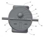
도 1은 본 발명에 따른 회전형 밀대 청소기의 외관 형상을 나타낸 사시도이다.
도 2는 본 발명에 따른 회전형 밀대 청소기의 구성을 나타낸 분해 사시도이다.
도 3과 도 4는 본 발명에 따른 회전형 밀대 청소기의 걸레판 구성을 설명하기 위한 부분 확대도이다.
도 5와 도 6은 본 발명에 따른 회전형 밀대 청소기의 동작 상태를 설명하기 위한 예시도이다.
도 7은 본 발명에 따른 회전형 밀대 청소기의 걸레판 회전부를 설명하기 위한 예시도이다.1 is a perspective view showing the external shape of a rotary push rod cleaner according to the present invention.
2 is an exploded perspective view showing the configuration of a rotary push rod cleaner according to the present invention.
3 and 4 are partially enlarged views for explaining the configuration of the mop plate of the rotary push rod cleaner according to the present invention.
5 and 6 are exemplary diagrams for explaining an operating state of the rotary push rod cleaner according to the present invention.
7 is an exemplary diagram for explaining a rotating part of a mop plate of a rotary push rod cleaner according to the present invention.
이하, 본 발명의 실시 예를 첨부된 도면들을 참조하여 상세하게 설명한다. 우선 각 도면의 구성 요소들에 참조 부호를 첨가함에 있어서, 동일한 구성 요소들에 대해서는 비록 다른 도면상에 표시되더라도 가능한 한 동일한 부호를 가지도록 하고 있음에 유의해야 한다. 또한, 본 발명을 설명함에 있어서, 관련된 공지 구성 또는 기능에 대한 구체적인 설명이 본 발명의 요지를 흐릴 수 있다고 판단되는 경우에는 그 상세한 설명은 생략한다.Hereinafter, embodiments of the present invention will be described in detail with reference to the accompanying drawings. First, in adding reference numerals to components of each drawing, it should be noted that the same components have the same numerals as much as possible even if they are displayed on different drawings. In addition, in describing the present invention, if it is determined that a detailed description of a related known configuration or function may obscure the gist of the present invention, the detailed description will be omitted.
도 1은 본 발명에 따른 회전형 밀대 청소기의 외관 형상을 나타낸 사시도이고, 도 2는 본 발명에 따른 회전형 밀대 청소기의 구성을 나타낸 분해 사시도이며, 도 3과 도 4는 본 발명에 따른 회전형 밀대 청소기의 걸레판 구성을 설명하기 위한 부분 확대도이고, 도 5와 도 6은 본 발명에 따른 회전형 밀대 청소기의 동작 상태를 설명하기 위한 예시도이며, 도 7은 본 발명에 따른 회전형 밀대 청소기의 걸레판 회전부를 설명하기 위한 예시도이다.1 is a perspective view showing the external shape of a rotary push rod cleaner according to the present invention, FIG. 2 is an exploded perspective view showing the configuration of a rotary push rod cleaner according to the present invention, and FIGS. 3 and 4 are a rotary push rod cleaner according to the present invention. It is a partially enlarged view for explaining the configuration of the mop plate of the push rod cleaner, FIGS. 5 and 6 are exemplary views for explaining the operating state of the rotary push rod cleaner according to the present invention, and FIG. 7 is the rotary push rod according to the present invention. It is an exemplary diagram for explaining the rotating part of the mop plate of the vacuum cleaner.
도 1 내지 도 7에 도시된 바와 같이, 본 발명의 밀어서 청소하는 회전형 밀대 청소기는 예를 들어, 쓸어내는 비 용도와 닦아내는 걸레 용도의 두 가지 기능을 하나로 묶어 필요에 따라 선택 사용이 가능하도록 된 것으로, 상부에 손잡이를 갖는 원통형 바(10)와, 원통형 바(10)의 하부에 흰지 체결되는 걸레판(20), 원통형 바(10)의 중간 부분에 걸레판(20)을 상하 방향으로 180도 회전시키는 걸레판 회전부(30)로 구성된다.As shown in FIGS. 1 to 7, the push-and-clean rotary push rod cleaner of the present invention, for example, combines two functions of sweeping rain and wiping mop into one so that it can be used selectively as needed. As a result, the
상기 원통형 바(10)의 내부에는 도 2에 도시된 바와 같이, 걸레판(20)을 상하 방향으로 180도 회전시키는 회전축(40)이 구비된다.As shown in FIG. 2, the
상기 원통형 바(10)와 상기 걸레판(20) 사이에는 일측이 개방되어 원통형 바(10)의 하단부가 삽입 체결되고, 타측에는 체결 날개(52)가 양쪽으로 형성되어 걸레판(20)과 흰지 체결되는 체결부재(50)가 더 구비된다.Between the
또한, 상기 회전축(40)의 하단부에는 도 2와 도 3에 도시된 바와 같이, 하부지면과 수평을 이루는 주동베벨기어(42)가 구비되고, 상기 주동베벨기어(42)의 하단 외주연에는 다수개의 이(43)가 형성되며, 그 중심에 결합돌기(미도시)가 돌출 구성된다. 여기서, 상기 결합돌기(미도시)는 회전축(40)이 회전시 이탈을 방지하는 이후에 설명할 볼트 커버(58)의 이탈 방지 구멍(미도시)에 삽입 고정된다.In addition, as shown in FIGS. 2 and 3 at the lower end of the rotating
상기 회전축(40)의 상부에는 하부지면과 수직을 이루는 중동베벨기어(46)가 구비되고, 상기 중동베벨기어(46)의 외주면에는 다수개의 이(47)가 형성된다.Middle and
한편, 상기 걸레판(20)은 도 3에 도시된 바와 같이 예를 들어, 정사각형 또는 직사각형의 판 형상으로 다양하게 구성되고, 일측 끝단이 고무 또는 실리콘 재질로 형성된 제1 걸레부(22)가 구성되며, 타측에는 천 또는 부직포 재질의 걸레를 감싸서 부착하는 걸레 부착부(25)가 양면에 형성된 제2 걸레부(24)가 구비된다.On the other hand, as shown in FIG. 3, the
상기 제1 걸레부(22)는 플라스틱과 고무 또는 실리콘 재질이 다양한 모양의 디자인에 따라 일체로 사출 성형된다.The
상기 걸레판(20)의 중심에는, 상기 체결부재(50)의 체결 날개(52)와 흰지 체결되는 체결 고리(26)가 돌출 형성되고, 상기 체결 고리(26)의 일측단부에는 상기 회전축(40)의 하단부에 구비된 주동베벨기어(42)와 맞물리는 종동베벨기어(27)가 형성된다.At the center of the
또한, 상기 체결부재(50)에 양쪽으로 구비된 체결 날개(52)의 외측면으로 볼트(56)와 볼트 커버(58) 및 너트(57)가 순차적으로 체결되어, 상기 걸레판(20)의 중심에 구비된 체결 고리(26)와 상기 체결 날개(52)들이 흰지 체결된다.In addition, the
여기서, 상기 볼트 커버(58)에는 일측 방향으로 이탈 방지 구멍(미도시)이 구비되고, 이 이탈 방지 구멍(미도시)에 상기 회전축(40) 하단부에 구비된 주동베벨기어(42)의 하단 중심에 돌출 형성된 결합돌기(미도시)가 삽입되어 회전축(40)이 회전시 주동베벨기어(42)에 형성된 다수개의 이(43)와 맞물려 회전되는 종동베벨기어(27)에 형성된 다수개의 이(27)가 서로 이탈되는 것을 방지한다.Here, the
한편, 상기 걸레판 회전부(30)는 도 6에 도시된 바와 같이, 상기 원통형 바(10)의 중간 부분에 양쪽으로 형성된 관통 구멍(미도시)에 끼워져 좌우 방향으로 이동되는 막대 형태의 회전 스위치(34)가 구비되고, 상기 회전 스위치(34)의 일측에는 상기 회전축(40)의 중앙에 구비된 중동베벨기어(46)와 맞물리는 다수개의 이(37)가 구비된다.On the other hand, as shown in FIG. 6, the mop
상기 회전 스위치(34)의 타측에는 걸림턱(38)이 양쪽으로 형성되고, 양쪽으로 형성된 걸림턱(38) 사이에는 상기 회전축(40)의 중동베벨기어(46)와 상기 회전 스위치(34)가 맞물리도록 지지하는 지지대(18)가 구비되며, 상기 지지대(18)의 끝단에는 탄성부재(19)가 구비된다.
상기 지지대(18)와 탄성부재(19)는 상기 회전 스위치(34)를 지지함과 아울러 상기 회전 스위치(34)가 일 방향으로 이동 범위를 벗어나지 못하도록 지지한다. 즉, 상기 회전 스위치(34)가 이동 범위를 벗어나는 경우 걸림턱(38)에 걸려 더 이상 이동되지 않게 된다.The
이와 같이, 구성된 본 발명에 따른 회전형 밀대 청소기는 도 4와 도 5에 도시된 바와 같이, 쓸어내는 비 기능과 닦아내는 걸레 기능을 사용자가 상기 걸레판 회전부(30)의 회전 스위치(34)를 도 6에 도시된 바와 같이 예를 들어, 좌 방향으로 밀거나 또는 우 방향으로 밀어서 사용하고자 하는 걸레판(20) 즉, 고무 또는 실리콘 재질로 형성된 제1 걸레부(22)가 바닥 방향으로 향하도록 180도 회전시키거나, 또는 천 또는 부직포 재질의 걸레를 감싸서 부착하는 걸레 부착부(25)가 양면에 형성된 제2 걸레부(24)가 바닥 방향으로 향하도록 180도 회전시켜 사용함으로써, 사용하지 않는 기능이 주변 물체에 걸리는 현상을 방지할 수 있고, 침대 밑과 같은 좁은 틈새에도 손쉽게 청소할 수 있는 장점이 있다.As shown in FIGS. 4 and 5, the rotary push rod cleaner according to the present invention configured as described above has a sweeping broom function and a wiping mop function when the user turns the
이상에서 설명한 바와 같이, 본 발명의 보호범위는 본 발명의 기술적 사상에 부합하는 의미와 개념으로 해석되어야만 할 것이며, 본 명세서나 도면에 제시된 사용예는 본 발명의 가장 바람직한 실시예에 불과할 뿐이고 본 발명의 기술사상을 모두 대변하는 것은 아니므로, 본 출원시점에 있어서 이들을 대체할 수 있는 다양한 균등물과 변형 예들이 있을 수 있음을 이해하여야 할 것이다.As described above, the protection scope of the present invention should be interpreted as meaning and concept consistent with the technical spirit of the present invention, and the examples of use presented in this specification or drawings are only the most preferred embodiments of the present invention, and the present invention Since it does not represent all of the technical ideas of, it should be understood that there may be various equivalents and modifications that can replace them at the time of this application.
10 : 원통형 바 18 : 지지대
19 : 탄성부재
20 : 걸레판 22 : 제1 걸레부
24 : 제2 걸레부 25 : 걸레 부착부
26 : 체결 고리 27 : 종동베벨기어
30 : 걸레판 회전부 34 : 회전 스위치
38 : 걸림턱
40 : 회전축 42 : 주동베벨기어
46 : 중동베벨기어
50 : 체결부재 52 : 체결 날개
56 : 볼트 57 : 너트
58 : 볼트 커버10: cylindrical bar 18: support
19: elastic member
20: mop plate 22: first mop unit
24: second mop part 25: mop attachment part
26: fastening ring 27: driven bevel gear
30: mop plate rotating part 34: rotary switch
38: snag
40: rotation axis 42: main bevel gear
46: middle east bevel gear
50: fastening member 52: fastening wing
56: bolt 57: nut
58: bolt cover
Claims (5)
Translated fromKorean상기 회전형 밀대 청소기는 원통형 바(10)와;
상기 원통형 바의 끝단부에 흰지 체결되는 걸레판(20);
상기 원통형 바의 중간 부분에 구비되어 걸레판을 상하 방향으로 180도 회전시키는 걸레판 회전부(30); 및
상기 원통형 바의 내측에는 걸레판을 상하 방향으로 180도 회전시키는 회전축(40)이 구비되되,
상기 원통형 바(10)와 상기 걸레판(20) 사이에는 일측이 개방되어 원통형 바가 삽입 체결되고, 타측에는 체결 날개(52)가 양쪽으로 형성되어 걸레판과 흰지 체결되는 체결부재(50)가 더 구비된 것을 특징으로 하는 회전형 밀대 청소기.In the rotary push rod cleaner for pushing and cleaning,
The rotary push rod cleaner includes a cylindrical bar (10);
A mop plate 20 fastened to the end of the cylindrical bar;
A mop plate rotation unit 30 provided at a middle portion of the cylindrical bar to rotate the mop plate 180 degrees in a vertical direction; and
The inside of the cylindrical bar is provided with a rotation shaft 40 for rotating the mop plate 180 degrees in the vertical direction,
Between the cylindrical bar 10 and the mop plate 20, one side is opened and a cylindrical bar is inserted and fastened, and fastening wings 52 are formed on both sides on the other side to further fasten the mop plate and white paper. Rotating push rod cleaner, characterized in that provided.
상기 걸레판(20)은 정사각형 또는 직사각형의 판 형상으로 구성되고,
일측 끝단이 고무 또는 실리콘 재질로 형성된 제1 걸레부(22)와,
타측에는 천 또는 부직포 재질의 걸레를 감싸서 부착하는 걸레 부착부(25)가 양면에 형성된 제2 걸레부(24)가 구비되고,
상기 걸레판(20)의 중심에는, 상기 체결부재(50)의 체결 날개(52)와 흰지 체결되는 체결 고리(26)가 돌출 형성된 것을 특징으로 하는 회전형 밀대 청소기.According to claim 1,
The mop plate 20 is composed of a square or rectangular plate shape,
A first mop part 22 having one end formed of rubber or silicon material;
On the other side, a second mop part 24 is provided with a mop attachment part 25 formed on both sides of a mop made of cloth or non-woven fabric and attached to the mop,
Rotating push rod cleaner, characterized in that in the center of the mop plate (20), a fastening ring (26) fastened with the fastening wing (52) of the fastening member (50) protrudes.
상기 회전축(40)의 하단부에는 하부지면과 수평을 이루는 주동베벨기어(42)가 구비되고, 상기 주동베벨기어(42)의 하단 외주연에는 다수개의 이(43)가 형성되며, 그 중심에 결합돌기가 돌출 구성되고, 상기 회전축(40)의 상부에는 하부지면과 수직을 이루는 중동베벨기어(46)가 구비되고, 상기 중동베벨기어(46)의 외주면에는 다수개의 이(47)가 형성된 것을 특징으로 하는 회전형 밀대 청소기.According to claim 1 or 2,
At the lower end of the rotating shaft 40, a main bevel gear 42 is provided that is level with the lower ground, and a plurality of teeth 43 are formed on the outer periphery of the lower end of the main bevel gear 42, and coupled to the center. The protrusion is configured to protrude, and the upper part of the rotation shaft 40 is provided with a middle-east bevel gear 46 perpendicular to the lower ground, and a plurality of teeth 47 are formed on the outer circumferential surface of the middle-east bevel gear 46. A rotary rolling pin cleaner.
상기 걸레판(20)의 중심에 돌출 형성된 체결 고리(26)의 일측단부에는 상기 회전축(40)의 하단부에 구비된 주동베벨기어(42)와 맞물리는 종동베벨기어(27)가 형성되고, 상기 체결부재(50)에 양쪽으로 구비된 체결 날개(52)의 외측면으로 볼트(56)와 볼트 커버(58) 및 너트(57)가 순차적으로 체결되어, 상기 걸레판(20)의 중심에 구비된 체결 고리(26)와 상기 체결 날개(52)들이 흰지 체결되는 것을 특징으로 하는 회전형 밀대 청소기.According to claim 3,
At one end of the fastening ring 26 protruding from the center of the mop plate 20, a driven bevel gear 27 meshing with the main bevel gear 42 provided at the lower end of the rotary shaft 40 is formed, and the A bolt 56, a bolt cover 58, and a nut 57 are sequentially fastened to the outer surface of the fastening wing 52 provided on both sides of the fastening member 50, provided at the center of the mop plate 20. A rotary push rod cleaner, characterized in that the fastening ring 26 and the fastening wings 52 are fastened.
상기 걸레판 회전부(30)는 원통형 바(10)의 중간 부분에 양쪽으로 형성된 관통 구멍에 끼워져 좌우 방향으로 이동되는 막대 형태의 회전 스위치(34)가 구비되고, 상기 회전 스위치(34)의 일측에는 상기 회전축(40)의 중앙에 구비된 중동베벨기어(46)와 맞물리는 다수개의 이(37)가 구비되고, 상기 회전 스위치(34)의 타측에는 걸림턱(38)이 양쪽으로 형성되고, 양쪽으로 형성된 걸림턱(38) 사이에는 상기 회전축(40)의 중동베벨기어(46)와 상기 회전 스위치(34)가 맞물리도록 지지하는 지지대(18)가 구비되며, 상기 지지대(18)의 끝단에는 탄성부재(19)가 구비된 것을 특징으로 하는 회전형 밀대 청소기.According to claim 3,
The mop plate rotating part 30 is provided with a rod-shaped rotary switch 34 that is inserted into through-holes formed on both sides of the middle portion of the cylindrical bar 10 and moves in the left and right directions, and one side of the rotary switch 34 A plurality of teeth 37 engaged with the middle-east bevel gear 46 provided at the center of the rotation shaft 40 are provided, and locking jaws 38 are formed on both sides of the other side of the rotary switch 34, and both sides A support 18 is provided between the locking jaws 38 formed to support the rotation switch 34 and the middle bevel gear 46 of the rotation shaft 40 to be engaged, and the end of the support 18 is elastic. Rotating push rod cleaner characterized in that the member (19) is provided.
Priority Applications (1)
| Application Number | Priority Date | Filing Date | Title |
|---|---|---|---|
| KR1020210125385AKR20230042427A (en) | 2021-09-20 | 2021-09-20 | Rotary push bar cleaner |
Applications Claiming Priority (1)
| Application Number | Priority Date | Filing Date | Title |
|---|---|---|---|
| KR1020210125385AKR20230042427A (en) | 2021-09-20 | 2021-09-20 | Rotary push bar cleaner |
Publications (1)
| Publication Number | Publication Date |
|---|---|
| KR20230042427Atrue KR20230042427A (en) | 2023-03-28 |
Family
ID=85800185
Family Applications (1)
| Application Number | Title | Priority Date | Filing Date |
|---|---|---|---|
| KR1020210125385ACeasedKR20230042427A (en) | 2021-09-20 | 2021-09-20 | Rotary push bar cleaner |
Country Status (1)
| Country | Link |
|---|---|
| KR (1) | KR20230042427A (en) |
Cited By (1)
| Publication number | Priority date | Publication date | Assignee | Title |
|---|---|---|---|---|
| WO2025188075A1 (en)* | 2024-03-07 | 2025-09-12 | 신철구 | Combination mop and broom |
Citations (1)
| Publication number | Priority date | Publication date | Assignee | Title |
|---|---|---|---|---|
| KR200312911Y1 (en) | 2003-01-03 | 2003-05-14 | 대곤 남 | Roller-type mop |
- 2021
- 2021-09-20KRKR1020210125385Apatent/KR20230042427A/ennot_activeCeased
Patent Citations (1)
| Publication number | Priority date | Publication date | Assignee | Title |
|---|---|---|---|---|
| KR200312911Y1 (en) | 2003-01-03 | 2003-05-14 | 대곤 남 | Roller-type mop |
Cited By (1)
| Publication number | Priority date | Publication date | Assignee | Title |
|---|---|---|---|---|
| WO2025188075A1 (en)* | 2024-03-07 | 2025-09-12 | 신철구 | Combination mop and broom |
Similar Documents
| Publication | Publication Date | Title |
|---|---|---|
| US6745434B2 (en) | Cleaning attachment for converting a cleaning implement to a mop | |
| US6779217B2 (en) | Appendage for a robot | |
| US8499406B2 (en) | Microfiber sweep mopcloth cleaning device | |
| JP3170819U (en) | Cleaning device | |
| US6701567B2 (en) | Cleaning attachment for converting a broom to a mop | |
| US9538895B1 (en) | Whisk broom with squeegee | |
| US8327501B2 (en) | Dustpan | |
| EP1868745B1 (en) | Flexible cleaning tool with replaceable non-woven pad and cleaning fluid reservoir | |
| US20080222825A1 (en) | Cleaning utensil with flexible peripheral regions | |
| KR20230042427A (en) | Rotary push bar cleaner | |
| US3503089A (en) | Corner brush | |
| US2831207A (en) | Reversible dust mop | |
| WO2019040687A2 (en) | Combination mop and broom | |
| EP1284630A2 (en) | Appendage for a robot for cleaning a surface | |
| US20050066458A1 (en) | Bathtub scrubbing brush | |
| JP2010110599A (en) | Wiper with handle having wholly flexible head | |
| CN209437177U (en) | cleaning device | |
| KR101778452B1 (en) | Cleaner of rotation type | |
| EP1419726B1 (en) | Cleaning attachment for converting a cleaning implement to a mop | |
| US10813523B2 (en) | Mop with advancing cleaning fabric material | |
| KR102864470B1 (en) | Mop and broom | |
| KR200428061Y1 (en) | Broom and Mop Sweep | |
| KR102240721B1 (en) | Case for broomstick | |
| KR102581392B1 (en) | Mop apparatus | |
| KR100714967B1 (en) | Multifunctional mop |
Legal Events
| Date | Code | Title | Description |
|---|---|---|---|
| PA0109 | Patent application | Patent event code:PA01091R01D Comment text:Patent Application Patent event date:20210920 | |
| PA0201 | Request for examination | Patent event code:PA02012R01D Patent event date:20211007 Comment text:Request for Examination of Application Patent event code:PA02011R01I Patent event date:20210920 Comment text:Patent Application | |
| E902 | Notification of reason for refusal | ||
| PE0902 | Notice of grounds for rejection | Comment text:Notification of reason for refusal Patent event date:20230221 Patent event code:PE09021S01D | |
| PG1501 | Laying open of application | ||
| E601 | Decision to refuse application | ||
| PE0601 | Decision on rejection of patent | Patent event date:20230503 Comment text:Decision to Refuse Application Patent event code:PE06012S01D Patent event date:20230221 Comment text:Notification of reason for refusal Patent event code:PE06011S01I |