KR20230041617A - End effector and substrate processing apparatus including end effector - Google Patents
End effector and substrate processing apparatus including end effectorDownload PDFInfo
- Publication number
- KR20230041617A KR20230041617AKR1020220114505AKR20220114505AKR20230041617AKR 20230041617 AKR20230041617 AKR 20230041617AKR 1020220114505 AKR1020220114505 AKR 1020220114505AKR 20220114505 AKR20220114505 AKR 20220114505AKR 20230041617 AKR20230041617 AKR 20230041617A
- Authority
- KR
- South Korea
- Prior art keywords
- end effector
- substrate
- chamber
- processing apparatus
- robot
- Prior art date
- Legal status (The legal status is an assumption and is not a legal conclusion. Google has not performed a legal analysis and makes no representation as to the accuracy of the status listed.)
- Pending
Links
Images


Classifications
- B—PERFORMING OPERATIONS; TRANSPORTING
- B65—CONVEYING; PACKING; STORING; HANDLING THIN OR FILAMENTARY MATERIAL
- B65G—TRANSPORT OR STORAGE DEVICES, e.g. CONVEYORS FOR LOADING OR TIPPING, SHOP CONVEYOR SYSTEMS OR PNEUMATIC TUBE CONVEYORS
- B65G47/00—Article or material-handling devices associated with conveyors; Methods employing such devices
- B65G47/74—Feeding, transfer, or discharging devices of particular kinds or types
- B65G47/90—Devices for picking-up and depositing articles or materials
- H—ELECTRICITY
- H01—ELECTRIC ELEMENTS
- H01L—SEMICONDUCTOR DEVICES NOT COVERED BY CLASS H10
- H01L21/00—Processes or apparatus adapted for the manufacture or treatment of semiconductor or solid state devices or of parts thereof
- H01L21/67—Apparatus specially adapted for handling semiconductor or electric solid state devices during manufacture or treatment thereof; Apparatus specially adapted for handling wafers during manufacture or treatment of semiconductor or electric solid state devices or components ; Apparatus not specifically provided for elsewhere
- H01L21/683—Apparatus specially adapted for handling semiconductor or electric solid state devices during manufacture or treatment thereof; Apparatus specially adapted for handling wafers during manufacture or treatment of semiconductor or electric solid state devices or components ; Apparatus not specifically provided for elsewhere for supporting or gripping
- H01L21/687—Apparatus specially adapted for handling semiconductor or electric solid state devices during manufacture or treatment thereof; Apparatus specially adapted for handling wafers during manufacture or treatment of semiconductor or electric solid state devices or components ; Apparatus not specifically provided for elsewhere for supporting or gripping using mechanical means, e.g. chucks, clamps or pinches
- H01L21/68707—Apparatus specially adapted for handling semiconductor or electric solid state devices during manufacture or treatment thereof; Apparatus specially adapted for handling wafers during manufacture or treatment of semiconductor or electric solid state devices or components ; Apparatus not specifically provided for elsewhere for supporting or gripping using mechanical means, e.g. chucks, clamps or pinches the wafers being placed on a robot blade, or gripped by a gripper for conveyance
- B—PERFORMING OPERATIONS; TRANSPORTING
- B25—HAND TOOLS; PORTABLE POWER-DRIVEN TOOLS; MANIPULATORS
- B25J—MANIPULATORS; CHAMBERS PROVIDED WITH MANIPULATION DEVICES
- B25J11/00—Manipulators not otherwise provided for
- B25J11/0095—Manipulators transporting wafers
- B—PERFORMING OPERATIONS; TRANSPORTING
- B25—HAND TOOLS; PORTABLE POWER-DRIVEN TOOLS; MANIPULATORS
- B25J—MANIPULATORS; CHAMBERS PROVIDED WITH MANIPULATION DEVICES
- B25J15/00—Gripping heads and other end effectors
- B25J15/0014—Gripping heads and other end effectors having fork, comb or plate shaped means for engaging the lower surface on a object to be transported
- B—PERFORMING OPERATIONS; TRANSPORTING
- B25—HAND TOOLS; PORTABLE POWER-DRIVEN TOOLS; MANIPULATORS
- B25J—MANIPULATORS; CHAMBERS PROVIDED WITH MANIPULATION DEVICES
- B25J9/00—Programme-controlled manipulators
- B25J9/0096—Programme-controlled manipulators co-operating with a working support, e.g. work-table
- B—PERFORMING OPERATIONS; TRANSPORTING
- B25—HAND TOOLS; PORTABLE POWER-DRIVEN TOOLS; MANIPULATORS
- B25J—MANIPULATORS; CHAMBERS PROVIDED WITH MANIPULATION DEVICES
- B25J9/00—Programme-controlled manipulators
- B25J9/02—Programme-controlled manipulators characterised by movement of the arms, e.g. cartesian coordinate type
- B25J9/04—Programme-controlled manipulators characterised by movement of the arms, e.g. cartesian coordinate type by rotating at least one arm, excluding the head movement itself, e.g. cylindrical coordinate type or polar coordinate type
- H—ELECTRICITY
- H01—ELECTRIC ELEMENTS
- H01L—SEMICONDUCTOR DEVICES NOT COVERED BY CLASS H10
- H01L21/00—Processes or apparatus adapted for the manufacture or treatment of semiconductor or solid state devices or of parts thereof
- H01L21/67—Apparatus specially adapted for handling semiconductor or electric solid state devices during manufacture or treatment thereof; Apparatus specially adapted for handling wafers during manufacture or treatment of semiconductor or electric solid state devices or components ; Apparatus not specifically provided for elsewhere
- H01L21/677—Apparatus specially adapted for handling semiconductor or electric solid state devices during manufacture or treatment thereof; Apparatus specially adapted for handling wafers during manufacture or treatment of semiconductor or electric solid state devices or components ; Apparatus not specifically provided for elsewhere for conveying, e.g. between different workstations
- H01L21/67739—Apparatus specially adapted for handling semiconductor or electric solid state devices during manufacture or treatment thereof; Apparatus specially adapted for handling wafers during manufacture or treatment of semiconductor or electric solid state devices or components ; Apparatus not specifically provided for elsewhere for conveying, e.g. between different workstations into and out of processing chamber
- H01L21/67742—Mechanical parts of transfer devices
- H—ELECTRICITY
- H01—ELECTRIC ELEMENTS
- H01L—SEMICONDUCTOR DEVICES NOT COVERED BY CLASS H10
- H01L21/00—Processes or apparatus adapted for the manufacture or treatment of semiconductor or solid state devices or of parts thereof
- H01L21/67—Apparatus specially adapted for handling semiconductor or electric solid state devices during manufacture or treatment thereof; Apparatus specially adapted for handling wafers during manufacture or treatment of semiconductor or electric solid state devices or components ; Apparatus not specifically provided for elsewhere
- H01L21/67005—Apparatus not specifically provided for elsewhere
- H01L21/67011—Apparatus for manufacture or treatment
- H01L21/67155—Apparatus for manufacturing or treating in a plurality of work-stations
- H01L21/67161—Apparatus for manufacturing or treating in a plurality of work-stations characterized by the layout of the process chambers
- H01L21/67167—Apparatus for manufacturing or treating in a plurality of work-stations characterized by the layout of the process chambers surrounding a central transfer chamber
- Y—GENERAL TAGGING OF NEW TECHNOLOGICAL DEVELOPMENTS; GENERAL TAGGING OF CROSS-SECTIONAL TECHNOLOGIES SPANNING OVER SEVERAL SECTIONS OF THE IPC; TECHNICAL SUBJECTS COVERED BY FORMER USPC CROSS-REFERENCE ART COLLECTIONS [XRACs] AND DIGESTS
- Y10—TECHNICAL SUBJECTS COVERED BY FORMER USPC
- Y10S—TECHNICAL SUBJECTS COVERED BY FORMER USPC CROSS-REFERENCE ART COLLECTIONS [XRACs] AND DIGESTS
- Y10S414/00—Material or article handling
- Y10S414/135—Associated with semiconductor wafer handling
- Y10S414/141—Associated with semiconductor wafer handling includes means for gripping wafer
- Y—GENERAL TAGGING OF NEW TECHNOLOGICAL DEVELOPMENTS; GENERAL TAGGING OF CROSS-SECTIONAL TECHNOLOGIES SPANNING OVER SEVERAL SECTIONS OF THE IPC; TECHNICAL SUBJECTS COVERED BY FORMER USPC CROSS-REFERENCE ART COLLECTIONS [XRACs] AND DIGESTS
- Y10—TECHNICAL SUBJECTS COVERED BY FORMER USPC
- Y10S—TECHNICAL SUBJECTS COVERED BY FORMER USPC CROSS-REFERENCE ART COLLECTIONS [XRACs] AND DIGESTS
- Y10S901/00—Robots
- Y10S901/30—End effector
Landscapes
- Engineering & Computer Science (AREA)
- Robotics (AREA)
- Physics & Mathematics (AREA)
- Condensed Matter Physics & Semiconductors (AREA)
- General Physics & Mathematics (AREA)
- Manufacturing & Machinery (AREA)
- Computer Hardware Design (AREA)
- Microelectronics & Electronic Packaging (AREA)
- Power Engineering (AREA)
- Mechanical Engineering (AREA)
- Container, Conveyance, Adherence, Positioning, Of Wafer (AREA)
- Manipulator (AREA)
Abstract
Description
Translated fromKorean본 개시는 일반적으로 엔드 이펙터에 관한 것이다. 보다 구체적으로, 본 개시의 예시적인 구현예는 기판을 이송하기 위한 엔드 이펙터, 및 엔드 이펙터를 포함한 기판 처리 장치에 관한 것이다.This disclosure relates generally to end effectors. More specifically, exemplary implementations of the present disclosure relate to an end effector for transferring a substrate, and a substrate processing apparatus including the end effector.
기판 처리 장치를 사용하는 공정은, 로봇 아암을 사용하여 기판을 전방 개방 통합 포드(FOUP)로부터 기판 핸들링 챔버 및 로드 록 챔버를 통해 처리 챔버로 이송하는 단계, 또는 로봇 아암을 사용하여 기판을 반응 챔버로부터 다른 반응 챔버로 이송하는 단계를 포함한다. 로봇 아암은, 기판을 그 위에 로딩하고 기판을 하나의 챔버에서 다른 챔버로 운반하기 위한 엔드 이펙터를 구비할 수 있다.A process using a substrate processing apparatus may include transferring a substrate from a front open integrated pod (FOUP) to a processing chamber using a robot arm through a substrate handling chamber and a load lock chamber, or using a robot arm to transfer a substrate into a reaction chamber. and transferring it to another reaction chamber. The robot arm may have end effectors for loading substrates thereon and for transferring substrates from one chamber to another.
전형적으로, 엔드 이펙터는 기판을 클램핑하기 위한 기계적 클램핑 메커니즘을 갖지 않고, 기판 위치 설정 또는 정렬 메커니즘(예, 미국 특허 출원 공개 제2012/0325148호, 미국 특허 제7,963,736호 및 미국 특허 제8,041,450호에 설명되고, 이들 각각의 개시는 그 전체가 참조로서 본원에 통합된 것들)에 의해, 기판은 전달하기 위해 엔드 이펙터 상에 위치한다. 기판은, 중력에 의해 초래되는, 엔드 이펙터의 표면에 대한 마찰에 의해 운반되는 동안에 엔드 이펙터 상에 유지된다.Typically, the end effector does not have a mechanical clamping mechanism to clamp the substrate, but a substrate positioning or alignment mechanism (e.g., as described in US Patent Application Publication No. 2012/0325148, US Patent No. 7,963,736 and US Patent No. 8,041,450). and by which the disclosures of each of these are incorporated herein by reference in their entirety), the substrate is placed on the end effector for delivery. The substrate is held on the end effector while being transported by friction against the surface of the end effector caused by gravity.
처리량이 증가함에 따라, 로봇 아암에 의한 전달 속도도 또한 증가한다. 전달 속도가 증가하는 경우, 기판이 마찰에 의해 엔드 이펙터 상에 남아 있기 때문에 기판은 때때로 엔드 이펙터에 대해 움직이고 제자리에서 미끄러져, 이에 의해 전달 오차를 야기하고 전달 안정성을 감소시킨다. 여러 개의 핀을 갖는 미끄럼 방지 엔드 이펙터가 움직임을 억제하는 데 사용된다. 예시적인 엔드 이펙터는 미국 특허 제9,370,863호에 개시되어 있으며, 이는 본원에 참조로 포함된다.As the throughput increases, the speed of delivery by the robot arm also increases. When the transfer speed increases, the substrate sometimes moves relative to the end effector and slips in place because the substrate remains on the end effector by friction, thereby causing transfer errors and reducing transfer stability. A non-slip end effector with multiple pins is used to inhibit motion. Exemplary end effectors are disclosed in US Pat. No. 9,370,863, incorporated herein by reference.
이 부분에서 진술된 문제점 및 해결책에 대한 임의의 논의를 포함하여 모든 논의는 단지 본 개시에 대한 맥락을 제공하는 목적으로 본 개시에 포함되었고, 그 논의의 일부 또는 전부가 본 발명이 이루어진 당시에 알려졌거나 달리 종래 기술을 구성하고 있음을 인정하는 것으로 받아들여져서는 안 된다.All discussion, including any discussion of problems and solutions addressed in this section, is included in this disclosure solely for the purpose of providing a context for this disclosure, and any part or all of the discussion was known or not known at the time the invention was made. It is not to be taken as an admission that otherwise constitutes prior art.
본 발명의 내용은 선정된 개념을 단순화된 형태로 소개하기 위해 제공된다. 이들 개념은 하기의 본 발명의 예시적 구현예의 상세한 설명에 더 상세하게 기재되어 있다. 본 발명의 내용은 청구된 요지의 주된 특징 또는 필수적인 특징을 구분하려는 의도가 아니며 청구된 요지의 범주를 제한하기 위해 사용하려는 의도 또한 아니다.This summary is provided to introduce selected concepts in a simplified form. These concepts are described in more detail in the detailed description of exemplary embodiments of the invention below. This summary is not intended to identify key features or essential features of the claimed subject matter, nor is it intended to be used to limit the scope of the claimed subject matter.
본 개시의 예시적인 구현예에 따라, 엔드 이펙터가 제공된다. 엔드 이펙터는, 기판을 위치시키기 위한 후방 돌출부를 근위 단부가 구비하는 패들; 패들로부터 연장되고, 기판을 지지하기 위한 원형 돌출부를 구비하는 링; 및 링으로부터 연장되고, 기판을 위치시키기 위한 전방 돌출부를 원위 단부가 구비하는 블레이드를 포함할 수 있다.According to an exemplary implementation of the present disclosure, an end effector is provided. The end effector includes a paddle having a proximal end with a rear projection for positioning a substrate; a ring extending from the paddle and having a circular protrusion for supporting a substrate; and a blade extending from the ring and having a distal end having a forward projection for positioning a substrate.
다양한 구현예에서, 원형 돌출부의 높이는 후방 돌출부 및 전방 돌출부의 높이보다 낮을 수 있다.In various embodiments, the height of the circular protrusion can be less than the heights of the posterior and anterior protrusions.
다양한 구현예에서, 원형 돌출부의 에지는 둥글 수 있다.In various embodiments, the edges of the circular protrusions can be rounded.
다양한 구현예에서, 둥근 에지는 반원형일 수 있다.In various embodiments, the rounded edge may be semi-circular.
다양한 구현예에서, 둥근 에지는 기판의 배면에 대해 측정했을 시 0.4 이상의 정적 마찰 계수를 갖는 상부면을 가질 수 있다.In various embodiments, the rounded edge may have a top surface having a static coefficient of friction greater than 0.4 as measured with respect to the back surface of the substrate.
다양한 구현예에서, 반원형은 1.0 mm 초과의 반경을 가질 수 있다.In various embodiments, the semi-circle can have a radius greater than 1.0 mm.
다양한 구현예에서, 엔드 이펙터는 Al2O3을 포함할 수 있다.In various embodiments, the end effector may include Al2O3.
다양한 구현예에서, 엔드 이펙터는 로봇 아암에 부착될 수 있다.In various implementations, the end effector can be attached to a robot arm.
다양한 구현예에서, 로봇 아암은 수직, 전방 및 후방, 및 측방향으로 이동하도록 구성될 수 있다.In various implementations, the robotic arm can be configured to move vertically, forward and backward, and laterally.
다양한 구현예에서, 기판 처리 장치는, 기판을 처리하기 위한 반응 챔버; 반응 챔버에 부착된 기판 처리 챔버; 기판 처리 챔버에 배치된 백엔드 로봇; 및 기판을 로딩하거나 언로딩하기 위한 로드 록 챔버로서, 상기 로드 록 챔버는 기판 핸들링 챔버에 부착되는, 로드록 챔버를 포함하되, 상기 백엔드 로봇은 로봇 아암 및 엔드 이펙터를 포함한다.In various implementations, a substrate processing apparatus includes a reaction chamber for processing a substrate; a substrate processing chamber attached to the reaction chamber; a back-end robot disposed in the substrate processing chamber; and a load lock chamber for loading or unloading substrates, the load lock chamber being attached to the substrate handling chamber, wherein the backend robot includes a robot arm and an end effector.
다양한 구현예에서, 복수의 센서는 반응 챔버와 기판 핸들링 챔버 사이에 배치될 수 있다.In various implementations, a plurality of sensors can be disposed between the reaction chamber and the substrate handling chamber.
다양한 구현예에서, 링의 직경은 복수의 센서 사이의 거리보다 작을 수 있다.In various implementations, the diameter of the ring may be smaller than the distance between the plurality of sensors.
본 개시의 예시적인 실시예에 대한 더 완전한 이해는 다음의 예시적인 도면과 관련하여 고려될 때, 발명의 상세한 설명 및 청구 범위를 참조함으로써 도출될 수 있다.
도 1은 본 발명의 일 구현예에서 사용 가능한 이중 챔버 모듈을 갖는 반도체 처리 장치의 개략적인 평면도이다.
도 2는 본 발명의 일 구현예에서 사용 가능한 이중 아암 웨이퍼-핸들링 로봇의 개략적인 평면도이다.
도 3은 본 발명의 일 구현예에 따른 엔드 이펙터의 개략적인 평면도이다.
도 4는 본 발명의 일 구현예에 따른 엔드 이펙터의 개략적인 단면도이다.
도면의 요소는 간략하고 명료하게 도시되어 있으며, 반드시 축적대로 도시되지 않았음을 이해할 것이다. 예를 들어, 본 개시에서 예시된 구현예의 이해를 돕기 위해 도면 중 일부 구성 요소의 치수는 다른 구성 요소에 비해 과장될 수 있다.A more complete understanding of exemplary embodiments of the present disclosure may be obtained by referring to the detailed description and claims when considered in conjunction with the following exemplary drawings.
1 is a schematic plan view of a semiconductor processing apparatus having a dual chamber module usable in one embodiment of the present invention.
2 is a schematic plan view of a dual arm wafer-handling robot usable in one embodiment of the present invention.
3 is a schematic plan view of an end effector according to an embodiment of the present invention.
4 is a schematic cross-sectional view of an end effector according to an embodiment of the present invention.
It will be appreciated that elements in the drawings are illustrated for simplicity and clarity and have not necessarily been drawn to scale. For example, dimensions of some components in the drawings may be exaggerated relative to other components to aid understanding of the embodiments illustrated in the present disclosure.
소정의 구현예가 아래에 개시되었지만, 당업자는 본 개시가 구체적으로 개시된 구현예 및/또는 본 개시의 용도 및 이들의 명백한 변형물 및 균등물을 넘어 확장된다는 것을 이해할 것이다. 따라서, 본 개시의 범위는 본 명세서에 설명된 특정 실시예들에 의해 제한되지 않아야 한다는 것이 의도된다.Although certain embodiments are disclosed below, those skilled in the art will understand that the present disclosure extends beyond the specifically disclosed embodiments and/or uses of the present disclosure and obvious modifications and equivalents thereof. Accordingly, it is intended that the scope of this disclosure should not be limited by the specific embodiments described herein.
본원에 제시된 예시는 임의의 특정한 재료, 장치, 구조, 또는 소자의 실제 뷰를 의도하려 하는 것은 아니며, 단지 본 발명의 구현예를 설명하기 위해 사용되는 이상화된 표현이다.The examples presented herein are not intended to be actual views of any particular material, device, structure, or element, but are merely idealized representations used to describe embodiments of the present invention.
본 개시에서, "가스"는 정상 온도 및 압력에서 가스, 증기화된 고체 및/또는 증기화된 액체인 재료를 포함할 수 있으며, 맥락에 따라 단일 가스 또는 가스 혼합물로 구성될 수 있다. 공정 가스 이외의 가스, 즉 샤워 플레이트 등의 가스 공급 유닛을 통과하지 않고 도입되는 가스는, 예를 들어 반응 공간을 밀폐하기 위해 사용될 수 있고, 희귀 가스 또는 기타 불활성 가스와 같은 밀폐 가스를 포함할 수 있다.In this disclosure, “gas” may include materials that are gases, vaporized solids, and/or vaporized liquids at normal temperature and pressure, and may consist of a single gas or a mixture of gases, depending on the context. Gas other than the process gas, that is, the gas introduced without passing through a gas supply unit such as a shower plate, may be used, for example, to seal the reaction space, and may contain a sealing gas such as a noble gas or other inert gas. there is.
본원에 사용되는 바와 같이, "기판"이라는 용어는 사용될 수 있거나 그 위에 장치, 회로 또는 필름이 형성될 수 있는 임의의 하부 재료 또는 재료들을 지칭할 수 있고, 이는 전형적으로 반도체 웨이퍼이다.As used herein, the term "substrate" can refer to any underlying material or materials that can be used or upon which a device, circuit or film can be formed, which is typically a semiconductor wafer.
본원에서 사용되는 바와 같이, 용어 "막" 및 "박막"은 본원에 개시된 방법에 의해 증착된 임의의 연속적인 또는 비연속적인 구조 및 재료를 지칭할 수 있다. 예컨대, "막" 및 "박막"은 2D 재료, 나노막대, 나노튜브 또는 나노입자 또는 심지어는 부분 또는 전체 분자층 또는 부분 또는 전체 원자층 또는 원자 및/또는 분자 클러스터를 포함할 수 있다. "막" 및 "박막"은 핀홀을 포함하는 재료 또는 층을 포함할 수 있지만, 여전히 적어도 부분적으로 연속적일 수 있다.As used herein, the terms “film” and “thin film” may refer to any continuous or non-continuous structures and materials deposited by the methods disclosed herein. For example, “film” and “thin film” may include 2D materials, nanorods, nanotubes or nanoparticles or even partial or full molecular layers or partial or full atomic layers or clusters of atoms and/or molecules. “Films” and “thin films” may include materials or layers that contain pinholes, but may still be at least partially continuous.
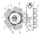
도 1은 본 발명의 일부 구현예에서 이중 챔버 모듈을 갖는 기판 처리 장치의 개략적인 평면도이다. 기판 처리 장치는 네 개의 이중 챔버 모듈(1a, 1b, 1c, 1d)(각각은 두 개의 반응기(2)를 구비함), 로드 록 챔버(5), 및 백 엔드 로봇(3)을 구비한 기판 핸들링 챔버(4)를 포함할 수 있고, 바람직하게는 이하에서 설명되는 시퀀스를 수행하도록 프로그래밍된 제어기를 함께 포함할 수 있으며, 이는 본 발명의 일부 구현예에서 사용될 수 있다.1 is a schematic plan view of a substrate processing apparatus having a dual chamber module in some embodiments of the present invention. The substrate processing apparatus includes four
본 구현예에서, 상기 기판 처리 장치는, (i) 네 개의 이중 챔버 모듈(1a-1d)(각각은, 일렬로 정렬된 전방부와 나란히 배열된 두 개의 반응 챔버(2)를 가짐); (ii) 두 개의 백 엔드 로봇(3)(기판 핸들링 로봇)을 포함하는 기판 핸들링 챔버(4)(각각은, 각각의 유닛의 두 개의 반응기에 동시에 접근 가능한 적어도 두 개의 엔드 이펙터를 갖고, 상기 기판 핸들링 챔버(4)는 네 개의 챔버 모듈(1a-1d)에 대응하고 이에 부착되는 네 개의 측면 및 로드 록 챔버(5)용 하나의 추가 측면을 각각 갖는 다각형 형상을 갖고, 모든 측면은 동일한 평면 상에 배치됨); 및 (iii) 두 개의 기판을 동시에 로딩 또는 언로딩하기 위한 로드 록 챔버(5)(로드 록 챔버(5)는 기판 핸들링 챔버(4)의 하나의 추가 측면에 부착되되, 각각의 백 엔드 로봇(3)은 로드 록 챔버(5)에 접근 가능함)를 포함할 수 있다.In this embodiment, the substrate processing apparatus includes: (i) four dual chamber modules 1a-1d, each having two reaction chambers 2 arranged side by side with front portions aligned in a row; (ii) a substrate handling chamber 4 comprising two back end robots 3 (substrate handling robots), each having at least two end effectors accessible simultaneously to two reactors of the respective unit, said substrate The handling chamber 4 has a polygonal shape each having four sides corresponding to and attached to the four chamber modules 1a-1d and one additional side for the load lock chamber 5, all sides being on the same plane. placed on); and (iii) a load lock chamber 5 for loading or unloading two substrates simultaneously (the load lock chamber 5 is attached to one additional side of the substrate handling chamber 4, and each bag end robot ( 3) may include a load lock chamber 5 accessible).
각각의 챔버(2)의 내부 및 로드 록 챔버(5)의 내부는, 게이트 밸브(9)에 의해 기판 핸들링 챔버(4)의 내부로부터 격리될 수 있다. 또한, 자동 웨이퍼 센터링(AWC) 센서(10a, 10b)는, 예를 들어 백 엔드 로봇(3)의 미리 결정된 위치에 대한 기판의 적어도 편심을 결정하기 위해, 각각의 챔버(2)와 기판 핸들링 챔버(4) 사이의 게이트 밸브(9) 근처에 배치될 수 있다.The inside of each chamber 2 and the inside of the load lock chamber 5 can be isolated from the inside of the substrate handling chamber 4 by a gate valve 9 . In addition, automatic wafer centering (AWC)
일부 구현예에서, 제어기(미도시)는, 예를 들어 기판 전달의 시퀀스를 실행하도록 프로그래밍된 소프트웨어를 저장할 수 있다. 제어기는 또한 각각의 반응 챔버의 상태를 확인할 수 있고, AWC 센서를 포함하는 센싱 시스템을 사용하여 각각의 반응 챔버에 기판을 위치시킬 수 있고, 각각의 모듈에 대한 가스 박스 및 전기 박스를 제어할 수 있고, FOUP(8) 및 로드 록 챔버(5)에 저장된 기판의 분포 상태에 기초하여 장비 프론트 엔드 모듈(6)에서 프론트 엔드 로봇(7)을 제어할 수 있고, 백 엔드 로봇(3)을 제어할 수 있고, 도 1에 나타낸 바와 같이 게이트 밸브(9)를 제어할 수 있다.In some implementations, a controller (not shown) may store software programmed to, for example, execute a sequence of substrate transfers. The controller may also check the status of each reaction chamber, position a substrate in each reaction chamber using a sensing system including an AWC sensor, and control the gas box and electrical box for each module. The front-end robot 7 can be controlled by the equipment front-end module 6 based on the distribution state of the substrates stored in the FOUP 8 and the load lock chamber 5, and the back-end robot 3 can be controlled. and control the gate valve 9 as shown in FIG.
당업자는 프로그램된, 그렇지 않으면 증착 및 본원의 다른 곳에서 설명되는 반응기 세정 공정이 수행되도록 구성된, 하나 이상의 제어기(들)가 장치에 포함된다는 것을 이해할 수 있다. 제어기(들)는, 당업자가 이해하는 바와 같이, 다양한 전력원, 가열 시스템, 펌프, 로보틱스, 및 반응기의 가스 유량 제어기 또는 밸브들과 통신할 수 있다.One skilled in the art will appreciate that the apparatus includes one or more controller(s) programmed and otherwise configured to perform the deposition and reactor cleaning processes described elsewhere herein. The controller(s) may communicate with various power sources, heating systems, pumps, robotics, and gas flow controllers or valves of the reactor, as will be understood by those skilled in the art.
일부 구현예에서, 장치는 한 개 초과의 임의의 수(예, 2, 3, 4, 5, 6 또는 7)의 챔버 모듈 및 반응 챔버를 가질 수 있다. 도 1에서, 장치는 여덟 개의 반응 챔버를 갖지만, 열 개 이상을 가질 수 있다. 일부 구현예에서, 모듈의 반응 챔버는 웨이퍼를 가공 또는 처리하기 위한 임의의 적절한 반응기일 수 있고, 플라즈마 강화 CVD 반응기 및 열 CVD 반응기와 같은 CVD 반응기, 플라즈마 강화 ALD 반응기 및 열 ALD 반응기와 같은 ALD 반응기, 에칭 반응기, 및 UV 경화 반응기를 포함할 수 있다. 전형적으로, 반응 챔버는 웨이퍼 상에 박막 또는 층을 증착하기 위한 플라즈마 반응기이다. 일부 구현예에서, 모든 모듈은, 언로딩/로딩이 순차적으로 그리고 규칙적으로 시간 지정될 수 있도록 웨이퍼를 처리하기 위한 동일한 능력을 갖는 동일한 유형일 수 있고, 이에 따라 생산성 또는 처리량을 증가시킨다. 일부 구현예에서, 모듈은 상이한 용량(예, 상이한 처리)을 가질 수 있지만, 모듈의 취급 시간은 실질적으로 동일하다.In some embodiments, a device can have more than one (eg, 2, 3, 4, 5, 6, or 7) chamber modules and reaction chambers. In Figure 1, the device has eight reaction chambers, but may have ten or more. In some implementations, the reaction chamber of the module can be any suitable reactor for processing or processing wafers, including CVD reactors such as plasma-enhanced CVD reactors and thermal CVD reactors, ALD reactors such as plasma-enhanced ALD reactors and thermal ALD reactors. , an etching reactor, and a UV curing reactor. Typically, the reaction chamber is a plasma reactor for depositing a thin film or layer on a wafer. In some implementations, all modules can be of the same type with the same capabilities for processing wafers so that unloading/loading can be sequentially and regularly timed, thereby increasing productivity or throughput. In some implementations, modules may have different capacities (eg, different treatments), but the handling times of the modules are substantially the same.
도 2는 본 발명의 일 구현예에서 사용할 수 있는 이중 아암 기판 핸들링 로봇의 개략적인 평면도이다. 엔드 이펙터(60)는 로봇 아암(20)에 부착되도록 구성될 수 있다. 일부 구현예에서, 이러한 유형의 이중 아암 기판 핸들링 로봇은 바람직하게는 도 1에 나타낸 장치에 사용될 수 있다. 그러나, 반응 챔버의 수가 네 개 이하일 경우, 예를 들어 단일 아암 웨이퍼 핸들링 로봇이 사용될 수 있다. 도 2에 나타낸 바와 같이, 로봇 아암(20)은 포크형 부분(22a), 중간 부분(22b), 및 바닥 부분(22c)으로 구성될 수 있다. 포크형 부분(22a)은 그 위에 기판을 지지하기 위한 엔드 이펙터(60)를 구비할 수 있다. 포크형 부분(22a) 및 중간 부분(22b)은 연결부(23a)를 통해 연결될 수 있고, 중간 부분(22b) 및 바닥 부분(22c)은 연결부(23b)를 통해 연결될 수 있고, 바닥 부분(22c)은 연결부(23c)를 통해 액추에이터(24)에 연결될 수 있다.2 is a schematic plan view of a dual arm substrate handling robot that can be used in one embodiment of the present invention.
일부 구현예에서, 임의의 적합한 기판 핸들링 로봇이, 미국 특허 제5,855,681호에 개시된 바와 같이 사용될 수 있고, 이는 그 전체가 본원에 참조로 포함되어 있다. 일부 구현예에서, 로봇 아암(20)은 포크형 부분 대신에 세 개의 웨이퍼를 한 번에 전달하기 위한 세 개의 프롱 부분을 가질 수 있다. 포크형 부분(22a)의 원위 단부는, 엔드 이펙터의 조인트 섹션(48)이 부착되는 조인트 부분(31L, 31R)을 구비할 수 있다. 이러한 로봇 아암은 X축을 따라 엔드 이펙터의 측방향 움직임을 제어하고, Y축을 따라 이의 전방 및 후방 움직임을 제어하고, Z축을 따라 이의 수직 움직임을 제어하고, 및 Z축에 대한 이의 회전 움직임을 제어할 수 있다.In some implementations, any suitable substrate handling robot can be used, as disclosed in US Pat. No. 5,855,681, which is incorporated herein by reference in its entirety. In some implementations, the
도 3은 본 발명의 일 구현예에 따른 엔드 이펙터의 개략적인 평면도이다. 엔드 이펙터(60)는 패들(45), 패들(45)로부터 연장되는 링(50), 링(50)으로부터 연장되는 좌측 블레이드(44b) 및 우측 블레이드(44a), 및 로봇 아암(20)에 부착되도록 구성된 조인트 섹션(48)을 포함할 수 있다. 블레이드(44b, 44a)의 원위 단부는, 웨이퍼가 미끄러지는 경우에 기판이 엔드 이펙터로부터 떨어지는 것을 억제하기 위해, 전방 돌출부(43b, 43a)를 각각 포함할 수 있다. 전방 돌출부(43a, 43b)는 또한 웨이퍼를 엔드 이펙터 상에 위치시키기 위해 사용될 수 있다.3 is a schematic plan view of an end effector according to an embodiment of the present invention.
패들(45)의 근위 단부는 또한 웨이퍼의 변위를 제한하기 위해, 후방 돌출부(47a, 47b)를 가질 수 있다. 링(50)은 원형 돌출부(52)를 포함할 수 있다. 원형 돌출부(52)는 미국 특허 제9,370,863호에 개시된 여러 개의 핀보다 기판 상에 더 많은 접촉점을 제공할 수 있다. 기판 위치 설정 영역은 전방 돌출부(43b, 43a) 및 후방 돌출부(47a, 47b)에 의해 정의될 수 있다.The proximal end of
일부 구현예에서, 엔드 이펙터(60)는 Al2O3을 포함할 수 있다. 기판 위치 설정 영역은, 예를 들어 약 300 mm의 길이를 가질 수 있다. 링(50)의 직경은 200 mm일 수 있으며, 이는 AWC 센서(10a, 10b) 사이의 거리보다 작다. 이는 AWC 센서(10a, 10b)가 링(50)을 기판으로서 잘못 감지하는 것으로부터 허용할 수 있다.In some implementations,
엔드 이펙터의 상부 표면으로부터 전방 돌출부(43a, 43b)의 높이는 약 4.5 mm일 수 있다. 또한, 바닥 표면으로부터의 원형 돌출부(52)의 높이는 약 3.7 mm일 수 있다. 바닥 표면으로부터 후방 돌출부(47)의 높이는, 예를 들어 약 4.8 mm일 수 있다. 상기 가변적인 수치는 일부 구현예에서 ±50%만큼 수정될 수 있는 반면, 원형 돌출부(52)의 높이는, 기판이 엔드 이펙터(60)로부터 떨어지는 것을 억제하기 위해, 후방 돌출부(47a, 47b) 및 전방 돌출부(43a, 43b)의 높이보다 낮을 수 있다.The height of the
도 4는 본 발명의 일 구현예에 따른 엔드 이펙터의 개략적인 단면도이다. 원형 돌출부(52)의 에지는 둥글 수 있다. 바람직하게는, 둥근 에지는 반원형일 수 있다. 일부 구현예에서, 반원 형상은 1.0 mm 초과 2.2 mm 미만의 반경을 가질 수 있다. 둥근 에지는 기판의 배면에 대해 측정했을 시 0.4 이상의 정적 마찰 계수를 갖는 상부면을 가질 수 있다.4 is a schematic cross-sectional view of an end effector according to an embodiment of the present invention. The edge of the
엔드 이펙터(60)가 미끄럼 방지 능력을 나타내는지 여부를 확인하기 위해, 엔드 이펙터 상에 베어 웨이퍼를 배치함으로써 웨이퍼 경사각 시험을 수행할 수 있다. 이 테스트는 웨이퍼가 슬라이딩을 시작하는 슬라이드 각도를 결정할 수 있다. 슬라이드 각도가 큰 경우, 웨이퍼 슬립이 억제될 수 있다.In order to confirm whether the
미국 특허 제9,370,863호에 개시된 종래의 엔드 이펙터.A conventional end effector disclosed in U.S. Patent No. 9,370,863.
베어 웨이퍼 경사 각도: 길이방향 7° / 측방향 8°Bare Wafer Tilting Angle: Longitudinal 7° / Lateral 8°
엔드 이펙터(60)End Effector(60)
베어 웨이퍼 경사 각도: 길이방향 17° / 측방향 18°Bare Wafer Tilting Angle: Longitudinal 17° / Lateral 18°
위에 설명된 본 개시의 예시적 구현예는 본 발명의 범주를 제한하지 않는데, 그 이유는 이들 구현예는 본 발명의 구현예의 예시일 뿐이기 때문이다. 임의의 균등한 구현예는 본 발명의 범주 내에 있도록 의도된다. 확실하게, 본원에 나타내고 설명된 것 외에도, 설명된 요소의 대안적인 유용한 조합과 같은 본 발명의 다양한 변경은 설명으로부터 당업자에게 분명할 수 있다. 이러한 변경예 및 구현예도 첨부된 청구범위의 범주 내에 있는 것으로 의도된다.The exemplary embodiments of the present disclosure described above do not limit the scope of the present invention, as these embodiments are only examples of embodiments of the present invention. Any equivalent implementations are intended to be within the scope of this invention. Certainly, in addition to those shown and described herein, various modifications of the present invention, such as alternative useful combinations of elements described, may become apparent to those skilled in the art from the description. Such variations and implementations are also intended to be within the scope of the appended claims.
Claims (12)
Translated fromKorean기판을 위치시키기 위한 후방 돌출부를 근위 단부가 구비하는 패들;
상기 패들로부터 연장되고, 상기 기판을 지지하기 위한 원형 돌출부를 구비하는 링; 및
상기 링으로부터 연장되고, 상기 기판을 위치시키기 위한 전방 돌출부를 원위 단부가 구비하는 블레이드를 포함하는, 엔드 이펙터.As an end effector for transferring a substrate,
a paddle having a proximal end with a rear projection for positioning a substrate;
a ring extending from the paddle and having a circular protrusion for supporting the substrate; and
and a blade extending from the ring and having a distal end having a forward projection for positioning the substrate.
기판을 처리하기 위한 반응 챔버;
상기 반응 챔버에 부착된 기판 핸들링 챔버;
상기 기판 핸들링 챔버 내에 배치된 백엔드 로봇; 및
상기 기판을 로딩 또는 언로딩하기 위한 로드 록 챔버로서, 상기 로드 록 챔버는 상기 기판 핸들링 챔버에 부착되는, 로드 록 챔버를 포함하되,
상기 백엔드 로봇은 제8항의 엔드 이펙터 및 상기 로봇 아암을 포함하는, 장치.As a substrate processing apparatus,
a reaction chamber for processing a substrate;
a substrate handling chamber attached to the reaction chamber;
a backend robot disposed within the substrate handling chamber; and
A load lock chamber for loading or unloading the substrate, the load lock chamber comprising a load lock chamber attached to the substrate handling chamber,
The apparatus, wherein the backend robot comprises the end effector of claim 8 and the robot arm.
Applications Claiming Priority (2)
| Application Number | Priority Date | Filing Date | Title |
|---|---|---|---|
| US202163245766P | 2021-09-17 | 2021-09-17 | |
| US63/245,766 | 2021-09-17 |
Publications (1)
| Publication Number | Publication Date |
|---|---|
| KR20230041617Atrue KR20230041617A (en) | 2023-03-24 |
Family
ID=85523597
Family Applications (1)
| Application Number | Title | Priority Date | Filing Date |
|---|---|---|---|
| KR1020220114505APendingKR20230041617A (en) | 2021-09-17 | 2022-09-08 | End effector and substrate processing apparatus including end effector |
Country Status (5)
| Country | Link |
|---|---|
| US (1) | US20230091979A1 (en) |
| JP (1) | JP2023044661A (en) |
| KR (1) | KR20230041617A (en) |
| CN (1) | CN115831855A (en) |
| TW (1) | TW202327973A (en) |
Families Citing this family (1)
| Publication number | Priority date | Publication date | Assignee | Title |
|---|---|---|---|---|
| TWI876090B (en) | 2020-09-08 | 2025-03-11 | 荷蘭商Asm Ip私人控股有限公司 | Method of replacing end effector, semiconductor processing system, and end effector jig |
- 2022
- 2022-09-08KRKR1020220114505Apatent/KR20230041617A/enactivePending
- 2022-09-13TWTW111134418Apatent/TW202327973A/enunknown
- 2022-09-14JPJP2022146468Apatent/JP2023044661A/enactivePending
- 2022-09-15CNCN202211120319.9Apatent/CN115831855A/enactivePending
- 2022-09-16USUS17/932,726patent/US20230091979A1/enactivePending
Also Published As
| Publication number | Publication date |
|---|---|
| US20230091979A1 (en) | 2023-03-23 |
| JP2023044661A (en) | 2023-03-30 |
| CN115831855A (en) | 2023-03-21 |
| TW202327973A (en) | 2023-07-16 |
Similar Documents
| Publication | Publication Date | Title |
|---|---|---|
| US9343350B2 (en) | Anti-slip end effector for transporting workpiece using van der waals force | |
| US9370863B2 (en) | Anti-slip end-effector for transporting workpiece | |
| US9793148B2 (en) | Method for positioning wafers in multiple wafer transport | |
| US20080138176A1 (en) | Apparatus for manufacturing semiconductor device | |
| US11414740B2 (en) | Processing system for forming layers | |
| EP1944799A2 (en) | High temperature robot end effector | |
| US11358809B1 (en) | Vacuum robot apparatus for variable pitch access | |
| US20200384636A1 (en) | Dual pitch end effector robot apparatus, dual pitch load locks, systems, and methods | |
| US11183411B2 (en) | Method of pre aligning carrier, wafer and carrier-wafer combination for throughput efficiency | |
| KR20230041617A (en) | End effector and substrate processing apparatus including end effector | |
| US11756816B2 (en) | Carrier FOUP and a method of placing a carrier | |
| KR20240060443A (en) | Method of measuring positional deviation of substrate stage and substrate processing apparatus | |
| KR20230106107A (en) | Remote plasma unit and substrate processing apparatus including remote plasma unit | |
| US20240198538A1 (en) | End effector and substrate processing apparatus including end effector | |
| US20240203777A1 (en) | Apparatus for treating substrate | |
| US20230326783A1 (en) | Substrate processing apparatus including substrate transfer robot | |
| US20250174483A1 (en) | Load lock arrangements configured for performing parallel processes, and associated systems and methods | |
| US20240387217A1 (en) | Equipment front end module | |
| KR20230106110A (en) | Remote plasma unit and substrate processing apparatus including remote plasma unit | |
| KR20240118672A (en) | Shared exhaust unit and substrate processing apparatus including shared exhaust unit | |
| KR20230111142A (en) | Substrate transport method and substrate processing system |
Legal Events
| Date | Code | Title | Description |
|---|---|---|---|
| E13-X000 | Pre-grant limitation requested | St.27 status event code:A-2-3-E10-E13-lim-X000 | |
| PA0109 | Patent application | St.27 status event code:A-0-1-A10-A12-nap-PA0109 | |
| P11-X000 | Amendment of application requested | St.27 status event code:A-2-2-P10-P11-nap-X000 | |
| P13-X000 | Application amended | St.27 status event code:A-2-2-P10-P13-nap-X000 | |
| PG1501 | Laying open of application | St.27 status event code:A-1-1-Q10-Q12-nap-PG1501 | |
| R17-X000 | Change to representative recorded | St.27 status event code:A-3-3-R10-R17-oth-X000 | |
| PA0201 | Request for examination | St.27 status event code:A-1-2-D10-D11-exm-PA0201 |