KR20230040176A - Cleaner system and controlling method thereof - Google Patents
Cleaner system and controlling method thereofDownload PDFInfo
- Publication number
- KR20230040176A KR20230040176AKR1020210123455AKR20210123455AKR20230040176AKR 20230040176 AKR20230040176 AKR 20230040176AKR 1020210123455 AKR1020210123455 AKR 1020210123455AKR 20210123455 AKR20210123455 AKR 20210123455AKR 20230040176 AKR20230040176 AKR 20230040176A
- Authority
- KR
- South Korea
- Prior art keywords
- dust
- motor
- cleaner
- suction
- door
- Prior art date
- Legal status (The legal status is an assumption and is not a legal conclusion. Google has not performed a legal analysis and makes no representation as to the accuracy of the status listed.)
- Pending
Links
- 238000000034methodMethods0.000titleclaimsabstractdescription24
- 239000000428dustSubstances0.000claimsabstractdescription900
- 230000008878couplingEffects0.000claimsdescription136
- 238000010168coupling processMethods0.000claimsdescription136
- 238000005859coupling reactionMethods0.000claimsdescription136
- 238000011084recoveryMethods0.000claimsdescription43
- 230000002441reversible effectEffects0.000description21
- 238000004140cleaningMethods0.000description20
- 238000001514detection methodMethods0.000description19
- 230000035515penetrationEffects0.000description19
- 230000008859changeEffects0.000description16
- 230000008901benefitEffects0.000description15
- 239000000126substanceSubstances0.000description15
- 238000003032molecular dockingMethods0.000description14
- 230000033001locomotionEffects0.000description13
- 238000010586diagramMethods0.000description12
- 230000001954sterilising effectEffects0.000description12
- 230000006835compressionEffects0.000description10
- 238000007906compressionMethods0.000description10
- 230000000694effectsEffects0.000description10
- 238000012790confirmationMethods0.000description9
- 238000004659sterilization and disinfectionMethods0.000description9
- 230000005484gravityEffects0.000description8
- 230000001788irregularEffects0.000description7
- 238000000926separation methodMethods0.000description7
- 230000002829reductive effectEffects0.000description5
- 239000000463materialSubstances0.000description3
- 230000009467reductionEffects0.000description3
- 241000894006BacteriaSpecies0.000description2
- 230000000903blocking effectEffects0.000description2
- 230000014509gene expressionEffects0.000description2
- 244000005700microbiomeSpecies0.000description2
- 230000004048modificationEffects0.000description2
- 238000012986modificationMethods0.000description2
- 235000019645odorNutrition0.000description2
- 230000036961partial effectEffects0.000description2
- 230000000149penetrating effectEffects0.000description2
- 238000003825pressingMethods0.000description2
- 239000010453quartzSubstances0.000description2
- 230000003014reinforcing effectEffects0.000description2
- VYPSYNLAJGMNEJ-UHFFFAOYSA-Nsilicon dioxideInorganic materialsO=[Si]=OVYPSYNLAJGMNEJ-UHFFFAOYSA-N0.000description2
- 241000700605VirusesSpecies0.000description1
- 238000005452bendingMethods0.000description1
- 230000005540biological transmissionEffects0.000description1
- 238000004891communicationMethods0.000description1
- 238000001816coolingMethods0.000description1
- 238000007599dischargingMethods0.000description1
- 230000005611electricityEffects0.000description1
- 238000001914filtrationMethods0.000description1
- 230000009931harmful effectEffects0.000description1
- 230000036541healthEffects0.000description1
- 230000006872improvementEffects0.000description1
- 230000007257malfunctionEffects0.000description1
- 230000013011matingEffects0.000description1
- 239000007769metal materialSubstances0.000description1
- 239000004745nonwoven fabricSubstances0.000description1
- 230000001151other effectEffects0.000description1
- 238000011045prefiltrationMethods0.000description1
- 230000008569processEffects0.000description1
- 230000001681protective effectEffects0.000description1
- 238000011012sanitizationMethods0.000description1
- 238000007789sealingMethods0.000description1
- 230000003068static effectEffects0.000description1
- 238000012546transferMethods0.000description1
- 238000002834transmittanceMethods0.000description1
- 210000000707wristAnatomy0.000description1
Images


Classifications
- A—HUMAN NECESSITIES
- A47—FURNITURE; DOMESTIC ARTICLES OR APPLIANCES; COFFEE MILLS; SPICE MILLS; SUCTION CLEANERS IN GENERAL
- A47L—DOMESTIC WASHING OR CLEANING; SUCTION CLEANERS IN GENERAL
- A47L9/00—Details or accessories of suction cleaners, e.g. mechanical means for controlling the suction or for effecting pulsating action; Storing devices specially adapted to suction cleaners or parts thereof; Carrying-vehicles specially adapted for suction cleaners
- A47L9/28—Installation of the electric equipment, e.g. adaptation or attachment to the suction cleaner; Controlling suction cleaners by electric means
- A47L9/2836—Installation of the electric equipment, e.g. adaptation or attachment to the suction cleaner; Controlling suction cleaners by electric means characterised by the parts which are controlled
- A47L9/2842—Suction motors or blowers
- A—HUMAN NECESSITIES
- A47—FURNITURE; DOMESTIC ARTICLES OR APPLIANCES; COFFEE MILLS; SPICE MILLS; SUCTION CLEANERS IN GENERAL
- A47L—DOMESTIC WASHING OR CLEANING; SUCTION CLEANERS IN GENERAL
- A47L9/00—Details or accessories of suction cleaners, e.g. mechanical means for controlling the suction or for effecting pulsating action; Storing devices specially adapted to suction cleaners or parts thereof; Carrying-vehicles specially adapted for suction cleaners
- A47L9/10—Filters; Dust separators; Dust removal; Automatic exchange of filters
- A47L9/14—Bags or the like; Rigid filtering receptacles; Attachment of, or closures for, bags or receptacles
- A47L9/149—Emptying means; Reusable bags
- A—HUMAN NECESSITIES
- A47—FURNITURE; DOMESTIC ARTICLES OR APPLIANCES; COFFEE MILLS; SPICE MILLS; SUCTION CLEANERS IN GENERAL
- A47L—DOMESTIC WASHING OR CLEANING; SUCTION CLEANERS IN GENERAL
- A47L5/00—Structural features of suction cleaners
- A47L5/12—Structural features of suction cleaners with power-driven air-pumps or air-compressors, e.g. driven by motor vehicle engine vacuum
- A47L5/22—Structural features of suction cleaners with power-driven air-pumps or air-compressors, e.g. driven by motor vehicle engine vacuum with rotary fans
- A47L5/24—Hand-supported suction cleaners
- A—HUMAN NECESSITIES
- A47—FURNITURE; DOMESTIC ARTICLES OR APPLIANCES; COFFEE MILLS; SPICE MILLS; SUCTION CLEANERS IN GENERAL
- A47L—DOMESTIC WASHING OR CLEANING; SUCTION CLEANERS IN GENERAL
- A47L7/00—Suction cleaners adapted for additional purposes; Tables with suction openings for cleaning purposes; Containers for cleaning articles by suction; Suction cleaners adapted to cleaning of brushes; Suction cleaners adapted to taking-up liquids
- A47L7/0095—Suction cleaners or attachments adapted to collect dust or waste from power tools
- A—HUMAN NECESSITIES
- A47—FURNITURE; DOMESTIC ARTICLES OR APPLIANCES; COFFEE MILLS; SPICE MILLS; SUCTION CLEANERS IN GENERAL
- A47L—DOMESTIC WASHING OR CLEANING; SUCTION CLEANERS IN GENERAL
- A47L9/00—Details or accessories of suction cleaners, e.g. mechanical means for controlling the suction or for effecting pulsating action; Storing devices specially adapted to suction cleaners or parts thereof; Carrying-vehicles specially adapted for suction cleaners
- A47L9/0009—Storing devices ; Supports, stands or holders
- A47L9/0063—External storing devices; Stands, casings or the like for the storage of suction cleaners
- A—HUMAN NECESSITIES
- A47—FURNITURE; DOMESTIC ARTICLES OR APPLIANCES; COFFEE MILLS; SPICE MILLS; SUCTION CLEANERS IN GENERAL
- A47L—DOMESTIC WASHING OR CLEANING; SUCTION CLEANERS IN GENERAL
- A47L9/00—Details or accessories of suction cleaners, e.g. mechanical means for controlling the suction or for effecting pulsating action; Storing devices specially adapted to suction cleaners or parts thereof; Carrying-vehicles specially adapted for suction cleaners
- A47L9/10—Filters; Dust separators; Dust removal; Automatic exchange of filters
- A47L9/106—Dust removal
- A—HUMAN NECESSITIES
- A47—FURNITURE; DOMESTIC ARTICLES OR APPLIANCES; COFFEE MILLS; SPICE MILLS; SUCTION CLEANERS IN GENERAL
- A47L—DOMESTIC WASHING OR CLEANING; SUCTION CLEANERS IN GENERAL
- A47L9/00—Details or accessories of suction cleaners, e.g. mechanical means for controlling the suction or for effecting pulsating action; Storing devices specially adapted to suction cleaners or parts thereof; Carrying-vehicles specially adapted for suction cleaners
- A47L9/10—Filters; Dust separators; Dust removal; Automatic exchange of filters
- A47L9/16—Arrangement or disposition of cyclones or other devices with centrifugal action
- A47L9/1683—Dust collecting chambers; Dust collecting receptacles
- A—HUMAN NECESSITIES
- A47—FURNITURE; DOMESTIC ARTICLES OR APPLIANCES; COFFEE MILLS; SPICE MILLS; SUCTION CLEANERS IN GENERAL
- A47L—DOMESTIC WASHING OR CLEANING; SUCTION CLEANERS IN GENERAL
- A47L9/00—Details or accessories of suction cleaners, e.g. mechanical means for controlling the suction or for effecting pulsating action; Storing devices specially adapted to suction cleaners or parts thereof; Carrying-vehicles specially adapted for suction cleaners
- A47L9/24—Hoses or pipes; Hose or pipe couplings
- A47L9/248—Parts, details or accessories of hoses or pipes
- A—HUMAN NECESSITIES
- A47—FURNITURE; DOMESTIC ARTICLES OR APPLIANCES; COFFEE MILLS; SPICE MILLS; SUCTION CLEANERS IN GENERAL
- A47L—DOMESTIC WASHING OR CLEANING; SUCTION CLEANERS IN GENERAL
- A47L9/00—Details or accessories of suction cleaners, e.g. mechanical means for controlling the suction or for effecting pulsating action; Storing devices specially adapted to suction cleaners or parts thereof; Carrying-vehicles specially adapted for suction cleaners
- A47L9/28—Installation of the electric equipment, e.g. adaptation or attachment to the suction cleaner; Controlling suction cleaners by electric means
- A47L9/2868—Arrangements for power supply of vacuum cleaners or the accessories thereof
- A47L9/2873—Docking units or charging stations
- A—HUMAN NECESSITIES
- A47—FURNITURE; DOMESTIC ARTICLES OR APPLIANCES; COFFEE MILLS; SPICE MILLS; SUCTION CLEANERS IN GENERAL
- A47L—DOMESTIC WASHING OR CLEANING; SUCTION CLEANERS IN GENERAL
- A47L5/00—Structural features of suction cleaners
- A47L5/12—Structural features of suction cleaners with power-driven air-pumps or air-compressors, e.g. driven by motor vehicle engine vacuum
- A47L5/22—Structural features of suction cleaners with power-driven air-pumps or air-compressors, e.g. driven by motor vehicle engine vacuum with rotary fans
- A47L5/24—Hand-supported suction cleaners
- A47L5/26—Hand-supported suction cleaners with driven dust-loosening tools
Landscapes
- Engineering & Computer Science (AREA)
- Mechanical Engineering (AREA)
- Robotics (AREA)
- Electric Vacuum Cleaner (AREA)
Abstract
Description
Translated fromKorean본 발명은 청소기 시스템 및 그 제어방법에 관한 것으로, 보다 상세하게는 외부의 먼지를 흡입하는 청소기 및 청소기에 저장된 먼지를 청소기 스테이션 내부로 흡입하는 청소기 스테이션을 구비한 청소기 시스템 및 그 제어방법에 관한 것이다.The present invention relates to a cleaner system and a control method thereof, and more particularly, to a cleaner system including a vacuum cleaner that sucks in dust from the outside and a cleaner station that sucks dust stored in the cleaner into the cleaner station, and a control method thereof. .
일반적으로 청소기는 전기를 이용하여 공기를 흡입하는 방식으로 작은 쓰레기나 먼지를 빨아들여 제품 속에 있는 먼지통에 채우는 가전기기로, 진공 청소기로 불리는 것이 일반적이다.BACKGROUND ART In general, a vacuum cleaner is a home appliance that sucks up small garbage or dust by sucking air using electricity and fills a dust bin in the product, and is commonly referred to as a vacuum cleaner.
이러한 청소기는 사용자가 직접 청소기를 이동시키면서 청소를 수행하기 위한 수동 청소기와, 스스로 주행하면서 청소를 수행하는 자동 청소기로 구분될 수 있다. 수동 청소기는 청소기의 형태에 따라, 캐니스터형 청소기, 업라이트 청소기, 핸디형 청소기 및 스틱형 청소기 등으로 구분될 수 있다.Such cleaners may be classified into manual cleaners for cleaning while a user directly moves the cleaner, and automatic cleaners for performing cleaning while driving by itself. Manual cleaners may be classified into canister-type cleaners, upright cleaners, handheld cleaners, and stick-type cleaners according to the shape of the cleaner.
가정용 청소기에서는 과거 캐니스터형 청소기가 많이 사용되었지만, 최근에는 먼지통과 청소기 본체를 일체로 제공하여 사용 편의성이 좋아진 핸디형 청소기와 스틱 청소기가 많이 사용되는 추세이다.In household cleaners, canister-type vacuum cleaners have been widely used in the past, but recently, handheld vacuum cleaners and stick vacuum cleaners, which provide convenience in use by integrally providing a dust bin and a cleaner body, have been widely used.
캐니스티형 청소기는 본체와 흡입구가 고무호스나 파이프로 연결되어 있고 경우에 따라 흡입구에 솔을 끼어서 사용 가능하다.The main body of the canister type vacuum cleaner is connected to the intake by a rubber hose or pipe, and in some cases, a brush can be inserted into the intake.
핸디형 청소기(Hand Vacuum Cleaner)는 휴대성을 극대화시킨 것으로, 무게가 가볍지만 길이가 짧기 때문에 앉아서 청소 영역에 제한이 있을 수 있다. 따라서, 책상 또는 소파 위나, 자동차 안과 같이 국부적인 장소를 청소하는데 사용된다.The Hand Vacuum Cleaner maximizes portability and is light in weight, but has a short length, so the cleaning area may be limited while sitting. Thus, it is used to clean localized areas, such as on a desk or sofa, or in a car.
스틱 청소기는 서서 사용할 수 있어 허리를 숙이지 않고도 청소가 가능하다. 따라서 넓은 영역을 이동하면서 청소하는데 유리하다. 핸디형 청소기가 좁은 공간의 청소를 한다면, 스틱형은 그보다는 넓은 공간 청소를 할 수 있고 손에 닿지 않는 높은 곳의 청소를 할 수 있다. 최근에는 스틱 청소기를 모듈 타입으로 제공하여 다양한 대상에 능동적으로 청소기 타입을 변경하여 사용하기도 한다.The stick vacuum cleaner can be used standing up, so you can clean without bending your back. Therefore, it is advantageous to clean while moving a large area. If the handheld vacuum cleaner cleans a narrow space, the stick type cleaner can clean a wider space and can clean high places that are out of reach. Recently, a stick cleaner is provided in a module type, and the cleaner type is actively changed and used for various objects.
또한, 최근에는 사용자의 조작 없이 스스로 청소를 수행하는 로봇 청소기가 사용되고 있다. 로봇 청소기는 청소하고자 하는 구역을 스스로 주행하면서 바닥으로부터 먼지 등의 이물질을 흡입함으로써, 청소하고자 하는 구역을 자동으로 청소한다.In addition, recently, a robot cleaner that self-cleans without a user's manipulation has been used. The robot cleaner automatically cleans the area to be cleaned by sucking foreign substances such as dust from the floor while traveling on its own in the area to be cleaned.
그러나, 종래의 핸디형 청소기와, 스틱 청소기와, 로봇 청소기는 집진된 먼지를 저장하는 먼지통의 용량이 작아 사용자가 매번 먼지통을 비워야 하는 번거로움이 있었다.However, conventional handheld vacuum cleaners, stick vacuum cleaners, and robot cleaners have a small capacity of dust bins for storing collected dust, so that users have to empty the dust bins every time.
또한, 먼지통을 비우게 되는 경우 먼지가 비산하여 사용자의 건강상 해로운 영향을 주는 문제가 있었다.In addition, when the dust bin is emptied, dust is scattered, which has a harmful effect on the user's health.
또한, 먼지통의 잔존 먼지가 제거되지 않는 경우 청소기의 흡입력을 저하하는 문제가 있었다.In addition, when remaining dust in the dust bin is not removed, there is a problem in that the suction power of the vacuum cleaner is reduced.
또한, 먼지통의 잔존 먼지가 제거되지 않는 경우 잔여물로 인한 악취가 발생하는 문제가 있었다.In addition, if the remaining dust in the dust bin is not removed, there is a problem in that a bad smell is generated due to the residue.
선행특허문헌 1로 한국 공개특허공보 제10-2020-0074001호에는 진공 청소기와 도킹 스테이션을 포함하는 청소 장치를 개시하고 있다.As
선행특허문헌 1은, 이물질이 집진되는 집진통을 포함하는 진공 청소기와 상기 집진통에 집진된 이물질을 제거하도록 상기 집진통과 연결되는 도킹 스테이션을 포함하고 상기 집진통이 상기 도킹 스테이션에 도킹되도록 마련되며 상기 도킹 스테이션에는 상기 도킹 스테이션에 도킹된 상기 집진통 내의 이물질과 내부 공기를 흡입하는 흡입장치를 포함하도록 구성되어 있다.
또한, 선행특허문헌 1은, 도킹 스테이션 내부에서 이물질을 포집하는 포집부를 포함하도록 구성되어 있다. 선행특허문헌 1에 따르면, 도킹 스테이션에 배치된 흡입장치가 가동되면, 부압에 의해서 집진통에 집진된 이물질을 빨아들이고, 포집부에 집진함으로써 청소기의 집진통을 청소하도록 구성된다.In addition,
일반적으로 청소기는 가정에 배치되어 사용되며, 가정에서 발생하는 이물질들은 다양한 종류가 있으며, 머리카락 등도 자주 발생된다. 특히, 머리카락의 경우 얇고 길게 형성되어 있으며, 청소기의 집진통에 집진되는 중에 집진통의 일 측에 걸리는 경우가 발생할 수도 있다.In general, vacuum cleaners are placed and used at home, and there are various types of foreign substances generated in the home, and hair and the like are often generated. In particular, in the case of hair, it is formed thin and long, and may be caught on one side of the dust collection container while being collected in the dust collection container of the vacuum cleaner.
전술한 바와 같이, 머리카락이 집진통의 일 측에 걸린 상태에서 도킹 스테이션의 흡입장치가 가동되면, 머리카락의 일 측은 집진통에 걸린 채 도킹 스테이션을 향하여 길게 늘어지며, 머리카락의 타 측은 도킹 스테이션 내부로 연장되고 포집부에 집진되지 못한다. 따라서, 상기 머리카락은 별도로 제거해야 하는 문제점이 있었다.As described above, when the suction device of the docking station is operated while hair is caught on one side of the dust collector, one side of the hair is extended toward the docking station while being caught in the dust collector, and the other side of the hair extends into the docking station. and cannot be collected in the collecting part. Therefore, there was a problem in that the hair had to be removed separately.
한편, 도킹 스테이션은 먼지통 커버를 자동으로 닫는 장치도 구비할 수 있다. 하지만, 전술한 바와 같이 머리카락은 일 측이 집진통에 걸린 채 먼지통 외부로 연장되는 바, 커버를 닫을 때 머리카락이 끼어 집진통을 완전히 밀폐할 수 없다는 문제점도 있었다.Meanwhile, the docking station may also include a device for automatically closing the dust bin cover. However, as described above, since the hair extends to the outside of the dust bin while one side is caught in the dust bin, there is a problem in that the dust dust bin cannot be completely sealed because the hair is caught when the cover is closed.
선행특허문헌 2로 한국 등록특허공보 제10-2208334호를 제시한다. 선행특허문헌 2는 진공청소기와 도킹스테이션을 포함하는 청소장치 및 그 제어방법을 개시한다.As Prior Patent Document 2, Korean Patent Registration No. 10-2208334 is proposed. Prior Patent Document 2 discloses a cleaning device including a vacuum cleaner and a docking station and a control method thereof.
선행특허문헌 2는 변칙적인 흡입기류를 제공하여, 청소기의 집진통의 이물질을 자동적이면서도 효과적으로 배출시키는 도킹 스테이션을 포함하는 청소장치를 제시한다.Prior Patent Document 2 proposes a cleaning device including a docking station that automatically and effectively discharges foreign substances from a dust collection box of a vacuum cleaner by providing an irregular suction device.
전술한 해결과제를 위하여, 선행특허문헌 2는 먼지통의 집진통에서 도킹 스테이션 내부로 공기를 이동시키는 흡입장치와, 흡입 유로를 개방 또는 폐쇄하는 유량조절장치를 구비한다. 제어부는 흡입장치를 동작하거나, 흡입장치가 동작하는 상태에서 주기적으로 흡입유로를 개폐하도록 유량조절장치를 제어한다. 선행특허문헌 2에 따르면, 유량조절장치에 의해서 유로가 개폐됨에 따라 유로 내부에서 변칙적인 공기유동이 발생하고, 변칙적인 공기유동으로 인하여 먼지가 보다 효율적으로 배출되는 효과를 제시한다.For the above-described problem, Prior Patent Document 2 includes a suction device for moving air from a dust container into a docking station and a flow control device for opening or closing the suction passage. The control unit operates the suction device or controls the flow control device to periodically open and close the suction flow path while the suction device is operating. According to Prior Patent Document 2, irregular air flow occurs inside the flow path as the flow path is opened and closed by the flow control device, and the irregular air flow presents an effect of discharging dust more efficiently.
하지만, 전술한 바와 같이 먼지통에 견고하게 걸려있는 머리카락 등 이물질은 선행특허문헌 2에서 발생된 변칙적인 공기유동에서도 제거되지 않을 수 있다.However, as described above, foreign substances such as hair firmly caught in the dust bin may not be removed even in the irregular air flow generated in Prior Patent Document 2.
선행특허문헌 3으로 미국 공개특허 제2021-0030244호를 제시한다. 선행문헌 3은 로봇청소기로부터 먼지를 제거하는 청소시스템을 제시한다.Prior Patent Document 3 proposes US Patent Publication No. 2021-0030244. Prior Document 3 proposes a cleaning system for removing dust from a robot cleaner.
선행특허문헌 3은 스테이션을 구비하며, 스테이션의 일 측에는 핸디청소기가 결합되고, 스테이션의 타 측에는 로봇청소기가 결합된다. 로봇청소기의 먼지통과 핸디청소기의 먼지통은 서로 연통되며, 로봇청소기의 흡입모터가 작동하면 로봇청소기의 먼지통에 집진된 먼지가 핸디청소기로 이동하며 로봇청소기의 먼지통을 비우는 발명이다.Prior Patent Document 3 has a station, a handheld cleaner is coupled to one side of the station, and a robot cleaner is coupled to the other side of the station. The dust bin of the robot cleaner and the dust bin of the handheld cleaner communicate with each other, and when the suction motor of the robot cleaner operates, dust collected in the dust bin of the robot cleaner moves to the handheld cleaner and empty the dust bin of the robot cleaner.
하지만, 선행특허문헌 3 또한 먼지의 유동방향이 일 방향으로 유지되는 바, 전술한 바와 같이 먼지통에 견고하게 걸려있는 머리카락 등 이물질은 선행특허문헌 3에 의하여도 제거될 수 없다는 문제점이 있다.However, prior patent document 3 also maintains the flow direction of dust in one direction, and as described above, there is a problem in that foreign substances such as hair firmly caught in the dust bin cannot be removed even by prior patent document 3.
본 발명은 상기한 바와 같은 종래 청소기 시스템 및 그 제어방법이 가지는 문제점들을 개선하기 위해 창출된 것이다. 구체적으로, 종래기술에 따를 때 머리카락 등의 이물질이 먼지통에 견고하게 걸려있는 경우에는, 흡입기류가 한 방향으로 유지되는 한 변칙적인 흡입기류가 형성되는 경우에도 걸려있는 이물질이 풀리지 않는다는 문제점이 있었다. 이에 본 발명이 해결하고자 하는 과제는, 공기유동을 정방향 및 역방향으로 전환시킴으로써 먼지통에 견고하게 걸려있는 이물질을 제거하고 청소기의 먼지통을 보다 효과적으로 비울 수 있는 청소기 시스템을 제공하는 것이다.The present invention was created to improve the problems of the conventional vacuum cleaner system and its control method as described above. Specifically, according to the prior art, when foreign matter such as hair is firmly caught in the dust bin, there is a problem that the foreign matter is not released even when an irregular inhaler is formed as long as the inhaler is maintained in one direction. Accordingly, an object to be solved by the present invention is to provide a vacuum cleaner system capable of removing foreign substances firmly caught in a dust bin and more effectively emptying the dust bin of a vacuum cleaner by switching air flow in forward and reverse directions.
또한, 머리카락 등의 긴 이물질이 분리할 수 없을 만큼 견고하게 걸려 먼지통의 배출구 주위에 잔존하는 경우, 먼지통의 배출구 주위에 잔존하는 먼지를 먼지통 내부로 회수하여, 배출 커버가 상기 배출구를 폐쇄할 때 먼지통이 완전히 밀폐될 수 있는 청소기 시스템을 제공함에 그 목적이 있다.In addition, when long foreign substances such as hair are so firmly caught that they cannot be separated and remain around the outlet of the dust bin, the dust remaining around the outlet of the dust bin is recovered into the dust bin, and when the discharge cover closes the outlet, the dust bin is recovered. Its purpose is to provide a vacuum cleaner system that can be completely sealed.
또한, 청소기 또는 청소기 스테이션의 구성요소들을 제어함으로써, 먼지통의 배출구 주위에 잔존하는 먼지를 제거할 수 있는 청소기 시스템의 제어방법을 제공함에 그 목적이 있다.Another object of the present invention is to provide a control method of a cleaner system capable of removing dust remaining around an outlet of a dust bin by controlling components of the cleaner or cleaner station.
또한, 먼지통의 배출구 주위에 잔존하는 먼지를 제거할 때, 흡입 모터 또는 집진 모터의 수명을 향상시키도록 제어하는 청소기 시스템 및 그 제어방법을 제공함에 그 목적이 있다.Another object of the present invention is to provide a cleaner system and a control method for improving the lifespan of a suction motor or a dust collecting motor when removing dust remaining around the outlet of a dust bin.
또한, 먼지통의 배출구 주위에 잔존하는 먼지를 제거할 때, 흡입 모터의 작은 회전속도로 효율적으로 먼지를 회수할 수 있는 청소기 시스템 및 그 제어방법을 제공함에 그 목적이 있다.Another object of the present invention is to provide a vacuum cleaner system capable of efficiently collecting dust at a small rotational speed of a suction motor when removing dust remaining around an outlet of a dust bin, and a control method thereof.
본 발명의 과제들은 이상에서 언급한 과제들로 제한되지 않으며, 언급되지 않은 또 다른 과제들은 아래의 기재로부터 당업자에게 명확하게 이해될 수 있을 것이다.The tasks of the present invention are not limited to the tasks mentioned above, and other tasks not mentioned will be clearly understood by those skilled in the art from the following description.
상기한 바와 같은 목적을 달성하기 위하여 본 발명에 의한 청소기 시스템은, 먼지를 집진하는 먼지통을 포함하는 청소기 및 청소기가 결합되는 청소기 스테이션을 포함한다. 청소기는 먼지통에 먼지를 포함한 공기가 유입되도록 흡입력을 발생시키는 흡입모터를 포함한다. 청소기 스테이션은, 하우징, 하우징에 수용되고 청소기가 결합된 때 먼지통의 먼지가 유동할 수 있는 유로부, 유로부의 하류에 배치되며 유로부를 통해 먼지통에 흡입력을 제공하는 집진모터를 포함한다. 이때, 흡입모터의 흡입력은 적어도 1회 이상 가변하고, 유로부에서 먼지의 유동방향은 적어도 1회 이상 반대 방향으로 전환된다.In order to achieve the above object, a cleaner system according to the present invention includes a cleaner including a dust bin for collecting dust and a cleaner station coupled with the cleaner. The vacuum cleaner includes a suction motor that generates a suction force so that air containing dust is introduced into the dust bin. The cleaner station includes a housing, a flow path portion accommodated in the housing and allowing dust in the dust bin to flow when the cleaner is coupled, and a dust collection motor disposed downstream of the flow path portion and providing a suction force to the dust bin through the flow path portion. At this time, the suction power of the suction motor is varied at least once, and the flow direction of the dust in the flow path is switched to the opposite direction at least once.
청소기 시스템에서, 흡입모터 또는 집진모터 중 적어도 어느 하나는 온오프(On-Off)됨으로써 제어될 수 있다.In the vacuum cleaner system, at least one of the suction motor and the dust collection motor may be controlled by being turned on and off.
집진모터는 구동을 시작한 후에 적어도 1회 이상 흡입력이 가변할 수 있다.The suction power of the dust collecting motor may be varied at least once or more after starting the driving.
흡입모터가 먼지통에 제공하는 흡입력의 방향은, 집진모터가 먼지통에 제공하는 흡입력의 방향과 반대될 수 있다.A direction of suction force provided by the suction motor to the dust container may be opposite to a direction of suction force provided by the dust collection motor to the dust container.
청소기 스테이션은, 청소기가 결합하는 결합부에 형성되고 먼지통과 유로부의 사이에 배치된 먼지통과홀과, 먼지통과홀을 개폐하는 도어를 포함할 수 있다. 이때, 도어는 흡입모터 또는 집진모터 중 적어도 어느 하나가 작동하기 전에 작동할 수 있다.The cleaner station may include a dust passage hole formed in a coupling part to which the cleaner is coupled and disposed between the dust bin and the flow path part, and a door that opens and closes the dust passage hole. At this time, the door may operate before at least one of the suction motor and the dust collection motor operates.
도어는 집진모터가 작동하기 전에 작동하여, 먼지통과홀을 완전히 개방할 수 있다. 먼지통과홀이 완전히 개방된 후, 흡입모터가 작동하기 전에 작동하여 먼지통과홀을 일부만 개방할 수 있다.The door is operated before the dust collection motor operates, so that the dust passage hole can be completely opened. After the dust passage hole is completely opened, the suction motor may be operated before the dust passage hole is partially opened.
본 발명의 제1실시예에 따르면, 집진모터는 지속적으로 작동하고, 흡입모터는 온오프됨으로써 제어될 수 있다. 이때, 흡입모터는 운전모드가 변경되면 집진모터가 작동한 후 작동을 시작할 수 있다.According to the first embodiment of the present invention, the dust collection motor continuously operates, and the suction motor can be controlled by turning on and off. At this time, the suction motor may start operating after the dust collecting motor operates when the operation mode is changed.
본 발명의 제2실시예에 따르면, 집진모터는 온오프됨으로써 제어되고, 흡입모터는 지속적으로 작동할 수 있다.According to the second embodiment of the present invention, the dust collection motor is controlled by being turned on and off, and the suction motor can be continuously operated.
흡입모터의 회전속도는, 제1흡입속도와, 제1흡입속도보다 작은 제2흡입속도를 포함할 수 있다.The rotational speed of the suction motor may include a first suction speed and a second suction speed smaller than the first suction speed.
본 발명의 제3실시예에 따르면, 흡입모터는 제1흡입속도와 제2흡입속도가 교번하여 나타나고, 회전속도가 변경되기 전에 소정 시간 오프될 수 있다. 이때, 집진모터는 흡입모터가 오프되는 동안 작동될 수 있다.According to the third embodiment of the present invention, the suction motor alternates between the first suction speed and the second suction speed, and may be turned off for a predetermined time before the rotational speed is changed. At this time, the dust collecting motor may be operated while the suction motor is turned off.
본 발명의 제4실시예에 따르면, 흡입모터는 제1흡입속도와 제2흡입속도가 교번하여 나타나고, 회전속도가 변경될 때 소정 시간동안 회전속도가 연속적으로 변경될 수 있다. 이때, 집진모터의 회전속도는 제1흡입속도보다 작을 수 있다.According to the fourth embodiment of the present invention, in the suction motor, the first suction speed and the second suction speed appear alternately, and the rotational speed can be continuously changed for a predetermined time when the rotational speed is changed. At this time, the rotational speed of the dust collecting motor may be smaller than the first suction speed.
상기한 바와 같은 목적을 달성하기 위하여 본 발명에 의한 청소기 시스템의 제어방법은, 먼지통과 먼지통에 먼지를 포함한 공기가 유입되도록 흡입력을 제공하는 흡입모터를 포함하는 청소기, 및 청소기가 결합하는 결합부와 청소기가 결합된 때 먼지통의 먼지가 유동할 수 있는 유로붕와 유로부의 하류에 배치되며 유로부를 통해 먼지통에 흡입력을 제공하는 집진모터를 포함하는 청소기 스테이션을 포함한다. 청소기 시스템의 제어방법은, 집진모터를 작동하여 먼지통의 먼지를 청소기 스테이션으로 흡입하는 집진단계와, 집진단계 이후 흡입모터를 작동하여 먼지통의 배출구에 존재하는 먼지를 먼지통 내부로 흡입하는 회수단계를 포함한다. 이때 회수단계는, 유동방향이 집진단계에서 유로부의 유동방향에 반대된다.In order to achieve the above object, a method for controlling a vacuum cleaner system according to the present invention includes a vacuum cleaner including a dust bin and a suction motor for providing suction power so that air containing dust is introduced into the dust bin, and a coupling part coupled to the vacuum cleaner. and a cleaner station including a flow path through which dust in the dust bin can flow when the cleaner is coupled, and a dust collection motor disposed downstream of the flow path and providing a suction force to the dust bin through the flow path. The control method of the vacuum cleaner system includes a dust collecting step of operating a dust collecting motor to suck dust from a dust bin into a cleaner station, and a collecting step of sucking dust present at the outlet of the dust bin into the inside of the dust bin by operating a suction motor after the dust collecting step. do. At this time, in the recovery step, the flow direction is opposite to the flow direction of the flow path in the dust collection step.
청소기 시스템의 제어방법은, 집진단계 전에 먼지통과홀을 완전히 개방하는 도어 완전개방 단계와, 회수단계에서 흡입모터를 작동하기 전에 먼지통과홀을 일부만 개방하는 도어 일부개방 단계를 포함할 수 있다. 이때, 먼지통과홀은 결합부에 형성되고, 먼지통과 유로부의 사이에 배치된다.The control method of the cleaner system may include a door completely opening step of completely opening the dust passage hole before the dust collection step, and a door partially opening step of partially opening the dust passage hole before operating the suction motor in the collecting step. At this time, the dust passage hole is formed in the coupling part and is disposed between the dust bin and the passage part.
상기한 바와 같은 목적을 달성하기 위하여 본 발명에 의한 청소기는, 먼지를 집진하는 먼지통과, 먼지통에 먼지를 포함한 공기가 유입되도록 흡입력을 발생시키는 흡입모터를 포함한다. 청소기는 먼지통에 연통되는 유로부와 유로부에 공기를 발생시키는 집진모터를 포함하는 청소기 스테이션에 결합된다. 청소기는 집진모터가 작동되면 유로부 내부에서 제1방향으로 공기유동이 형성되고, 흡입모터가 작동되면 유로부 내부에서 제1방향에 반대되는 제2방향으로 공기유동이 형성된다.In order to achieve the above object, the vacuum cleaner according to the present invention includes a dust bin for collecting dust and a suction motor for generating a suction force so that air containing dust is introduced into the dust bin. The cleaner is coupled to a cleaner station including a flow path part communicating with the dust bin and a dust collection motor generating air in the flow path part. In the vacuum cleaner, when the dust collecting motor is operated, air flow is formed inside the flow path in a first direction, and when the suction motor is operated, air flow is formed inside the flow path in a second direction opposite to the first direction.
흡입모터는 집진모터가 적어도 1회 작동한 후 작동될 수 있다.The suction motor may be operated after the dust collecting motor operates at least once.
먼지통과홀은 먼지통과 유로부의 사이에 배치되고, 먼지의 유동방향이 전환되기 전에 단면적의 크기가 변경될 수 있다.The dust passing hole may be disposed between the dust bin and the flow path, and may have a cross-sectional size changed before the flow direction of dust is changed.
흡입모터는 유로부의 유동방향이 전환되도록 흡입력이 가변할 수 있다.The suction motor may have a variable suction force so that the flow direction of the flow path part is changed.
이상에서 설명한 바와 같이 본 발명에 따른 청소기 시스템 및 그 제어방법에 의하면 다음과 같은 효과가 하나 혹은 그 이상 있다.As described above, according to the vacuum cleaner system and the control method according to the present invention, one or more of the following effects are provided.
첫째, 집진단계에서 먼지를 청소기 스테이션으로 흡입하고, 회수단계에서 먼지를 먼지통 내부로 다시 흡입하여 회수하고, 상기 유동방향의 전환은 적어도 1회 이상 이루어지는 바, 집진단계에서 먼지통에 견고하게 걸려있는 이물질이 정방향의 공기유동에 강한 저항을 가지고 있을 때, 회수단계에서 역방향의 공기유동을 인가하여 상기 이물질을 효과적으로 제거할 수 있다는 장점이 있다.First, in the dust collection step, the dust is sucked into the cleaner station, and in the collection step, the dust is sucked back into the dust bin to be collected, and the flow direction is switched at least once, so that foreign substances firmly caught in the dust bin in the dust collection step When there is strong resistance to the air flow in the forward direction, there is an advantage in that the foreign matter can be effectively removed by applying the air flow in the reverse direction in the recovery step.
둘째, 집진 단계에서 먼지를 청소기 스테이션으로 흡입하고, 회수 단계에서 청소기의 먼지통의 배출구에 잔존하는 먼지를 먼지통 내부로 다시 흡입하여 회수하는 바, 먼지통의 일 측에 걸려 먼지통의 배출구까지 연장된 머리카락 등의 먼지를 먼지통 내부로 다시 회수하여, 배출커버로 먼지통의 배출구를 덮을 때 먼지통을 완전히 밀폐시킬 수 있다는 장점이 있다.Second, in the dust collection step, the dust is sucked into the cleaner station, and in the collection step, the dust remaining at the outlet of the dust bin of the cleaner is sucked back into the dust bin to be collected, such as hair caught on one side of the dust bin and extending to the outlet of the dust bin. There is an advantage in that the dust bin can be completely sealed when the dust bin is recovered back to the inside of the dust bin and the outlet of the dust bin is covered with the discharge cover.
셋째, 회수 단계 전에 도어 유닛을 작동시킴으로써 먼지 통과 홀의 면적을 감소시키는 바, 먼지 통과 홀에서 유속이 증가하여 흡입 모터가 작은 회전 속도로 작동하더라도 배출구 주위에 잔존하는 먼지를 효과적으로 제거하므로, 전력을 효율적으로 활용할 수 있다는 장점도 있다.Thirdly, by operating the door unit before the recovery step, the area of the dust passage hole is reduced. The flow rate in the dust passage hole is increased to effectively remove the dust remaining around the discharge port even when the suction motor operates at a small rotation speed, so that power is efficiently It also has the advantage of being usable.
넷째, 흡입 모터 또는 집진 모터를 온오프 제어하거나, 회전 속도를 변경함으로써 제어하는 바, 간편한 방법의 제어로 유로의 방향을 전환하여 먼지통의 배출구 주위에 잔존하는 먼지를 제거할 수 있다는 장점도 있다.Fourth, since the suction motor or the dust collection motor is controlled by turning on/off or changing the rotation speed, there is also an advantage in that dust remaining around the outlet of the dust bin can be removed by changing the direction of the passage through a simple control method.
본 발명의 효과들은 이상에서 언급한 효과들로 제한되지 않으며, 언급되지 않은 또 다른 효과들은 청구범위의 기재로부터 당업자에게 명확하게 이해될 수 있을 것이다.The effects of the present invention are not limited to the effects mentioned above, and other effects not mentioned will be clearly understood by those skilled in the art from the description of the claims.
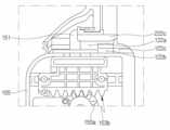
도 1은 본 발명의 실시예에 따른 청소기 스테이션과 청소기로 구성된 청소기 시스템에 대한 사시도이다.
도 2는 본 발명의 실시예에 따른 청소기 시스템의 구성에 대한 개략도이다.
도 3은 본 발명의 실시예에 따른 청소기 시스템에서 청소기를 설명하기 위한 도면이다.
도 4는 본 발명의 실시예에 따른 제1 청소기의 먼지 분리부 및 싸이클론 필터를 설명하기 위한 도면이다.
도 5는 본 발명의 실시예에 따른 제1 청소기의 먼지통 하측 면을 설명하기 위한 도면이다.
도 6은 본 발명의 실시예에 따른 청소기 스테이션에서 결합부를 설명하기 위한 도면이다.
도 7은 본 발명의 실시예에 따른 청소기 스테이션에서 고정 유닛을 설명하기 위한 분해 사시도이다.
도 8은 본 발명의 실시예에 따른 청소기 스테이션에서 제1 청소기와 도어 유닛의 관계를 대하여 설명하기 위한 도면이다.
도 9는 본 발명의 실시예에 따른 청소기 스테이션에서 제1 청소기와 커버 개방 유닛의 관계를 대하여 설명하기 위한 도면이다.
도 10은 본 발명의 실시예에 따른 청소기 스테이션에서 제어 구성을 설명하기 위한 블록도이다.
도 11은 본 발명의 실시예에 따른 청소기 시스템이 작동하는 단계를 설명하기 위한 순서도이다.
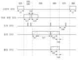
도 12는 본 발명의 실시예에 따른 청소기 시스템의 제어방법에서 시간 경과에 따른 모터 각각의 작동을 설명하기 위한 도면이다.
도 13은 본 발명의 실시예에 따른 청소기 시스템의 제어방법에서 도어 유닛의 작동에 따른 회수 단계를 설명하기 위한 도면이다.
도 14는 도 13에서 도어 유닛의 작동에 따른 배출 커버의 개폐 정도를 나타낸 도면이다.
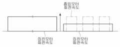
도 15는 본 발명의 제1실시예에 따른 흡입 모터와 집진 모터의 작동을 나타낸 도면이다.
도 16는 본 발명의 제2실시예에 따른 흡입 모터와 집진 모터의 작동을 나타낸 도면이다.
도 17는 본 발명의 제3실시예에 따른 흡입 모터와 집진 모터의 작동을 나타낸 도면이다.
도 18는 본 발명의 제4실시예에 따른 흡입 모터와 집진 모터의 작동을 나타낸 도면이다.1 is a perspective view of a cleaner system including a cleaner station and a cleaner according to an embodiment of the present invention.
2 is a schematic diagram of a configuration of a cleaner system according to an embodiment of the present invention.
3 is a diagram for explaining a cleaner in a cleaner system according to an embodiment of the present invention.
4 is a view for explaining a dust separator and a cyclone filter of a first cleaner according to an embodiment of the present invention.
5 is a view for explaining a lower surface of a dust bin of a first cleaner according to an embodiment of the present invention.
6 is a diagram for explaining a coupling part in a cleaner station according to an embodiment of the present invention.
7 is an exploded perspective view illustrating a fixing unit in a cleaner station according to an embodiment of the present invention.
8 is a diagram for explaining a relationship between a first cleaner and a door unit in a cleaner station according to an embodiment of the present invention.
9 is a diagram for explaining a relationship between a first cleaner and a cover opening unit in a cleaner station according to an embodiment of the present invention.
10 is a block diagram for explaining a control configuration in a cleaner station according to an embodiment of the present invention.
11 is a flowchart for explaining the operation of the cleaner system according to an embodiment of the present invention.
12 is a diagram for explaining the operation of each motor according to the lapse of time in the control method of the vacuum cleaner system according to the embodiment of the present invention.
13 is a view for explaining a recovery step according to the operation of a door unit in a control method of a cleaner system according to an embodiment of the present invention.
FIG. 14 is a view showing the degree of opening and closing of the discharge cover according to the operation of the door unit in FIG. 13 .
15 is a view showing the operation of the suction motor and the dust collection motor according to the first embodiment of the present invention.
16 is a view showing the operation of a suction motor and a dust collection motor according to a second embodiment of the present invention.
17 is a diagram showing the operation of a suction motor and a dust collection motor according to a third embodiment of the present invention.
18 is a diagram showing the operation of a suction motor and a dust collection motor according to a fourth embodiment of the present invention.
이하 첨부된 도면을 참조하여 본 발명의 바람직한 실시예를 상세히 설명하기로 한다.Hereinafter, preferred embodiments of the present invention will be described in detail with reference to the accompanying drawings.
본 발명은 다양한 변경을 가할 수 있고 여러 가지 실시예를 가질 수 있는 바, 특정 실시예들을 도면에 예시하고 상세한 설명에 구체적으로 설명하고자 한다. 이는 본 발명을 특정한 실시 형태에 대해 한정하려는 의도는 아니며, 본 발명의 사상 및 기술 범위에 포함되는 모든 변경, 균등물 내지 대체물을 포함하는 것으로 해석되어야 한다.Since the present invention can make various changes and have various embodiments, specific embodiments will be illustrated in the drawings and described in detail in the detailed description. This is not intended to limit the present invention to specific embodiments, and should be construed as including all changes, equivalents, or substitutes included in the spirit and technical scope of the present invention.
본 출원에서 사용한 용어는 단지 특정한 실시예를 설명하기 위해 사용된 것으로, 본 발명을 한정하려는 의도가 아니다. 단수의 표현은 문맥상 명백하게 다르게 뜻하지 않는 한, 복수의 표현을 포함할 수 있다.Terms used in this application are only used to describe specific embodiments, and are not intended to limit the present invention. Singular expressions may include plural expressions unless the context clearly dictates otherwise.
다르게 정의되지 않는 한, 기술적이거나 과학적인 용어를 포함해서 여기서 사용되는 모든 용어들은 본 발명이 속하는 기술 분야에서 통상의 지식을 가진 자에 의해 일반적으로 이해되는 것과 동일한 의미를 가질 수 있다. 일반적으로 사용되는 사전에 정의되어 있는 것과 같은 용어들은 관련 기술의 문맥상 가지는 의미와 일치하는 의미를 가지는 것으로 해석될 수 있으며, 본 출원에서 명백하게 정의하지 않는 한, 이상적이거나 과도하게 형식적인 의미로 해석되지 않을 수 있다.Unless defined otherwise, all terms used herein, including technical or scientific terms, may have the same meaning as commonly understood by a person of ordinary skill in the art to which the present invention belongs. Terms such as those defined in commonly used dictionaries may be interpreted as having a meaning consistent with the meaning in the context of the related art, and unless explicitly defined in the present application, interpreted in an ideal or excessively formal meaning. It may not be.
도 1에는 본 발명의 실시예에 따른 청소기 스테이션과 청소기로 구성된 청소기 시스템에 대한 사시도가 개시되고, 도 2에는 본 발명의 실시예에 따른 청소기 시스템의 구성에 대한 개략도가 개시되어 있다.FIG. 1 is a perspective view of a cleaner system including a cleaner station and a cleaner according to an embodiment of the present invention, and FIG. 2 is a schematic diagram of a configuration of the cleaner system according to an embodiment of the present invention.
도 1 및 도 2를 참조하면, 본 명세서의 일 실시예에 따른 청소기 시스템 (10)은 청소기 스테이션(100)과, 청소기(200)를 포함할 수 있다. 한편, 본 실시예에서는 이 중 일부의 구성을 제외하고 실시될 수도 있고, 이외 추가적인 구성을 배제하지도 않는다.Referring to FIGS. 1 and 2 , a
청소기 시스템(10)은 청소기 스테이션(100)을 포함할 수 있다. 청소기 스테이션(100)에는 청소기(200)가 결합될 수 있다. 구체적으로, 청소기 스테이션(100)의 측면에는 청소기(200)가 결합될 수 있다. 청소기 스테이션(100)은 청소기(200)의 먼지통(220)의 먼지를 제거할 수 있다.The
한편, 도 3에는 본 발명의 실시예에 따른 청소기 시스템에서 청소기(200)를 설명하기 위한 도면이 개시되고, 도 4에는 본 발명의 실시예에 따른 청소기(200)의 먼지 분리부 및 싸이클론 필터를 설명하기 위한 도면이 개시되며, 도 5에는 본 발명의 실시예에 따른 청소기(200)의 먼지통 하측 면을 설명하기 위한 도면이 개시되어 있다.Meanwhile, FIG. 3 shows a drawing for explaining the cleaner 200 in the cleaner system according to an embodiment of the present invention, and FIG. 4 shows a dust separator and a cyclone filter of the cleaner 200 according to an embodiment of the present invention. A drawing for explaining is disclosed, and FIG. 5 is a drawing for explaining a lower surface of the dust bin of the cleaner 200 according to an embodiment of the present invention.
먼저, 도 1 내지 도 5를 참조하여 청소기(200)의 구조를 설명하면 다음과 같다.First, the structure of the cleaner 200 will be described with reference to FIGS. 1 to 5 .
청소기(200)는 사용자가 수동으로 조작하는 청소기를 의미할 수 있다. 예를 들어, 청소기(200)는 핸디형 청소기나, 스틱 청소기를 의미할 수 있다.The cleaner 200 may refer to a cleaner manually operated by a user. For example, the cleaner 200 may mean a handheld cleaner or a stick cleaner.
청소기(200)는 청소기 스테이션(100)에 거치될 수 있다. 청소기(200)는 청소기 스테이션(100)에 의해 지지될 수 있다. 청소기(200)는 청소기 스테이션(100)에 결합될 수 있다.The cleaner 200 may be mounted on the
한편, 본 발명의 일 실시예에서는 지면 위에 먼지통(220) 및 배터리 하우징(230)의 바닥면(하측 면)을 놓았을 때를 기준으로 방향을 정의할 수 있다.Meanwhile, in one embodiment of the present invention, the direction may be defined based on when the
이때, 전방이란 흡입 모터(214)를 기준으로 흡입부(212)가 배치되는 방향이고, 후방이란 핸들(216)이 배치되는 방향을 의미할 수 있다. 그리고, 흡입 모터(214)에서 흡입부(212)를 바라볼 때를 기준으로 오른쪽에 배치되는 방향을 우측이라 부를 수 있고, 왼쪽에 배치되는 방향을 좌측이라 부를 수 있다. 또한, 본 발명의 일 실시예에서는 지면 위에 먼지통(220) 및 배터리 하우징(230)의 바닥면(하측 면)을 놓았을 때를 기준으로 지면과 수직한 방향을 따라 상측 및 하측을 정의할 수 있다.In this case, the front may mean a direction in which the
청소기(200)는 본체(210)를 포함할 수 있다. 본체(210)는 본체 하우징(211), 흡입부(212), 먼지 분리부(213), 흡입 모터(214), 공기 배출 커버(215), 핸들(216) 및 조작부(218)를 포함할 수 있다.The cleaner 200 may include a
본체 하우징(211)은 청소기(200)의 외관을 이룰 수 있다. 본체 하우징(211)은 흡입 모터(214)와 필터(미도시)를 내부에 수용할 수 있는 공간을 제공할 수 있다. 본체 하우징(211)은 원통에 유사한 형태로 구성될 수 있다.The
흡입부(212)는 본체 하우징(211)에서 외측으로 돌출될 수 있다. 일 예로, 흡입부(212)는 내부가 개구된 원통 형상으로 형성될 수 있다. 흡입부(212)는 연장관(250)과 결합될 수 있다. 흡입부(212)는 먼지를 포함하는 공기가 유동할 수 있는 유로(이하, '흡입 유로'라고 부를 수 있다.)를 제공할 수 있다.The
한편, 본 실시예에서는 원통 형상으로 구성된 흡입부(212)의 내부를 관통하는 가상의 선을 형성할 수 있다. 즉, 흡입 유로를 길이 방향으로 관통하는 가상의 흡입 유로 관통선(a2)을 형성할 수 있다.Meanwhile, in the present embodiment, an imaginary line passing through the inside of the
먼지 분리부(213)는 흡입부(212)와 연통될 수 있다. 먼지 분리부(213)는 흡입부(212)를 통해 내부로 흡입된 먼지를 분리할 수 있다. 먼지 분리부(213) 내부의 공간은 먼지통(220) 내부의 공간과 연통될 수 있다.The
예를 들어, 먼지 분리부(213)는 싸이클론 유동에 의해 먼지를 분리할 수 있는 싸이클론부를 적어도 둘 이상 구비할 수 있다. 그리고, 먼지 분리부(213) 내부의 공간은 상기 흡입 유로와 연통될 수 있다. 따라서, 흡입부(212)를 통하여 흡입되는 공기와 먼지는 먼지 분리부(213)의 내주면을 따라 나선 유동하게 된다. 따라서, 먼지 분리부(213)의 내부 공간에서 싸이클론 유동이 발생할 수 있다.For example, the
먼지 분리부(213)는 흡입부(212)와 연통되며, 흡입부(212)를 통해 본체(210)의 내부로 흡입된 먼지를 분리하기 위해, 원심력을 이용하는 집진기의 원리를 적용한 구성이다.The
일 예로, 먼지 분리부(213)는 싸이클론 유동에 의해서 먼지를 분리할 수 있는 싸이클론을 적어도 하나 포함할 수 있다. 싸이클론은 흡입부(212)와 연통될 수 있다. 흡입부(212)를 통하여 흡입되는 공기와 먼지는 싸이클론의 내주면을 따라 나선 유동하게 된다.For example, the
먼지 분리부(213)는 싸이클론에서 배출된 공기에서 먼지를 재차 분리하는 2차 싸이클론을 더 포함할 수 있다. 이때, 먼지 분리부의 크기가 최소화되도록 2차 싸이클론은 싸이클론의 내부에 위치될 수 있다. 2차 싸이클론은 병렬로 배치되는 다수의 싸이클론 바디를 포함할 수 있다. 싸이클론에서 배출된 공기는 다수의 싸이클론 바디로 나뉘어 통과될 수 있다.The
이때, 2차 싸이클론의 싸이클론 유동의 축 또한 상하 방향으로 연장될 수 있으며, 싸이클론의 싸이클론 유동의 축과 2차 싸이클론의 싸이클론 유동의 축은 상하 방향으로 동축을 형성할 수 있으며, 이는 먼지 분리부(213)의 싸이클론 유동의 축으로 통칭될 수 있다. 한편, 본 실시예에서는 상기의 싸이클론 유동의 축에 대하여 가상의 싸이클론 선(a4)을 형성할 수 있다.At this time, the axis of the cyclone flow of the secondary cyclone may also extend in the vertical direction, and the axis of the cyclone flow of the cyclone and the axis of the cyclone flow of the secondary cyclone may form a coaxial axis in the vertical direction, This may be collectively referred to as an axis of the cyclone flow of the
먼지 분리부(213)는 2차 싸이클론부를 둘러싸도록 배치되는 싸이클론 필터(219)를 더 포함할 수도 있다. 싸이클론 필터(219)는 일 예로 원통 형태로 형성되며 싸이클론에서 먼지와 분리된 공기를 2차 싸이클론으로 안내한다. 싸이클론 필터(213a)는 공기가 통과하는 과정에서 먼지를 필터링할 수 있다.The
이를 위하여 싸이클론 필터(219)는 복수의 구멍을 가지는 메쉬부(mesh portion)를 포함할 수 있다. 상기 메쉬부는 제한적이지는 않으나, 금속 재질로 형성될 수 있다.To this end, the
흡입 모터(214)는 공기를 흡입시키는 흡입력을 발생시킬 수 있다. 상기 흡입력에 의하여, 먼지를 포함한 공기가 먼지통(220)에 유입된다. 흡입 모터(214)는 본체 하우징(211) 내에 수용될 수 있다. 흡입 모터(214)는 회전에 의하여 흡입력을 발생시킬 수 있다. 일 예로, 흡입 모터(214)는 원통 형태와 유사하게 구비될 수 있다.The
한편, 본 실시예에서는 흡입 모터(214)의 회전축을 연장한 가상의 흡입 모터 축선(a1)을 형성할 수 있다.Meanwhile, in the present embodiment, a virtual suction motor axis a1 extending the rotational axis of the
공기 배출 커버(215)는 본체 하우징(211)의 축 방향 일측에 배치될 수 있다. 공기 배출 커버(215)에는 공기를 필터링하기 위한 필터가 수용될 수 있다. 일 예로, 공기 배출 커버(215)에는 헤파(HEPA) 필터가 수용될 수 있다.The
공기 배출 커버(215)에는 흡입 모터(214)의 흡입력에 의하여 흡입된 공기를 배출시키는 공기 배출구(215a)가 형성될 수 있다.An air discharge port 215a may be formed in the
공기 배출 커버(215)에는 유동 가이드가 배치될 수 있다. 유동 가이드는 공기 배출구(215a)를 통하여 배출되는 공기의 유동을 가이드할 수 있다.A flow guide may be disposed on the
핸들(216)은 사용자에 의해 파지될 수 있다. 핸들(216)은 흡입 모터(214)의 후방에 배치될 수 있다. 일 예로, 핸들(216)은 원기둥 형태와 유사하게 형성될 수 있다. 또는, 핸들(216)은 구부러진 원기둥 형태로 형성될 수 있다. 핸들(216)은 본체 하우징(211) 또는 흡입 모터(214) 또는 먼지 분리부(213)와 소정 각도를 이루어 배치될 수 있다.The
핸들(216)은 사용자가 잡을 수 있도록 기둥 형태로 형성된 파지부(216a), 파지부(216a)의 길이 방향(축 방향) 일측 단부에 연결되고 흡입 모터(214)를 향하여 연장 형성되는 제1 연장부(216b) 및 파지부(216a)의 길이 방향(축 방향) 타측 단부에 연결되고, 먼지통(220)을 향하여 연장 형성되는 제2 연장부(216c)를 포함할 수 있다.The
한편, 본 실시예에서는 파지부(216a)의 길이 방향(기둥의 축 방향)을 따라 연장 형성되고, 파지부(216a)를 관통하는 가상의 파지부 관통선(a3)을 형성할 수 있다.Meanwhile, in the present embodiment, a virtual gripping part penetration line a3 extending along the longitudinal direction of the gripping part 216a (axial direction of the column) and penetrating the gripping part 216a may be formed.
일 예로, 파지부 관통선(a3)은 원기둥 형태의 핸들(216) 내부에 형성된 가상의 선일 수 있고, 파지부(216a)의 외측면(외주면) 중 적어도 일부와 평행하게 형성된 가상의 선일 수 있다.For example, the gripping part penetration line a3 may be a virtual line formed inside the
핸들(216)의 상면은 청소기(200)의 상면의 일부 외관을 형성할 수 있다. 이를 통해, 사용자가 핸들(216)을 파지하는 경우 청소기(200)의 일 구성이 사용자의 팔에 접촉되는 것을 방지할 수 있다.The upper surface of the
제1 연장부(216b)는 파지부(216a)에서 본체 하우징(211) 또는 흡입 모터(214)을 향해 연장될 수 있다. 제1 연장부(216b)의 적어도 일부는 수평 방향으로 연장될 수 있다.The
제2 연장부(216c)는 파지부(216a)에서 먼지통(220)을 향해 연장될 수 있다. 제2 연장부(216c)의 적어도 일부는 수평 방향으로 연장될 수 있다.The
조작부(218)는 핸들(216)에 배치될 수 있다. 조작부(218)는 핸들(216)의 상부 영역에 형성되는 경사면에 배치될 수 있다. 사용자는 조작부(218)를 통하여 청소기(200)의 동작이나 정지 명령을 입력할 수 있다.
청소기(200)는 먼지통(220)을 포함할 수 있다. 먼지통(220)은 먼지 분리부(213)와 연통될 수 있다. 먼지통(220)은 먼지 분리부(213)에서 분리된 먼지를 저장할 수 있다.The cleaner 200 may include a
먼지통(220)은 먼지통 본체(221), 배출 커버(222), 먼지통 압축 레버(223) 및 압축자(미도시)를 포함할 수 있다.The
먼지통 본체(221)는 먼지 분리부(213)에서 분리된 먼지를 저장할 수 있는 공간을 제공할 수 있다. 일 예로, 먼지통 본체(221)는 원통 형태와 유사하게 형성될 수 있다.The
한편, 본 실시예에서는 먼지통 본체(221)의 내부(내부 공간)를 관통하고, 먼지통 본체(221)의 길이 방향(원통 형태의 먼지통 본체(221)에서 축 방향을 의미함)을 따라 연장 형성된 가상의 먼지통 관통선(a5)을 형성할 수 있다.On the other hand, in the present embodiment, the
먼지통 본체(221)의 하측 면(바닥면)은 일부가 개방될 수 있다. 또한, 먼지통 본체(221)의 하측 면(바닥면)에는 하면 연장부(221a)가 형성될 수 있다. 하면 연장부(221a)는 먼지통 본체(221)의 하측 면 일부를 막도록 형성될 수 있다.A lower surface (bottom surface) of the
먼지통(220)은 배출 커버(222)를 포함할 수 있다. 배출 커버(222)는 먼지통(220)의 하측 면에 배치될 수 있다.The
배출 커버(222)는 먼지통 본체(221)의 길이 방향 일측 단부를 개폐하도록 구비될 수 있다. 구체적으로 배출 커버(222)는 하방으로 개구되는 먼지통(220)의 하부를 선택적으로 개폐시킬 수 있다.The
먼지통(220)은 일 측에 배출구가 형성된다. 먼지통(220)에 집진된 먼지는 상기 배출구를 통하여 버려질 수 있다. 상기 배출구는 먼지통(220)의 하부에 형성될 수 있다.The
배출 커버(222)는 커버 본체(222a) 및 힌지부(222b)를 포함할 수 있다. 커버 본체(222a)는 먼지통 본체(221)의 하측 면 일부를 막도록 형성될 수 있다. 커버 본체(222a)는 힌지부(222b)를 기준으로 하방으로 회전할 수 있다. 힌지부(222b)는 배터리 하우징(230)과 인접하게 배치될 수 있다. 일 예로, 힌지부(222b)는 토션스프링(222d)을 포함할 수 있다. 따라서, 배출 커버(222)가 먼지통 본체(221)에서 분리될 경우, 토션스프링(222d)의 탄성력에 의하여, 커버 본체(222a)는 먼지통 본체(221)에서 힌지부(222b)를 축으로 하여 소정 각도 이상 회전한 상태로 지지될 수 있다.The
배출 커버(222)는 후크 결합을 통해 먼지통(220)과 결합될 수 있다. 한편, 배출 커버(222)는 결합 레버(222c)를 통해 먼지통(220)에서 분리될 수 있다. 결합 레버(222c)는 먼지통의 전방에 배치될 수 있다. 구체적으로, 결합 레버(222c)는 먼지통(220)의 전방 측 외측면에 배치될 수 있다. 외력 인가 시, 결합 레버(222c)는 커버 본체(222a)와 먼지통 본체(221)의 후크 결합을 해제시키도록 커버 본체(222a)에서 연장 형성된 후크를 탄성 변형시킬 수 있다.The
배출 커버(222)가 닫혀있는 경우, 먼지통(220)의 하측 면은 배출 커버(222) 및 하면 연장부(221a)에 의하여 막힐(실링될) 수 있다.When the
먼지통(220)은 먼지통 압축 레버(223)를 포함할 수 있다(도 8 참조). 먼지통 압축 레버(223)는 먼지통(220) 또는 먼지 분리부(211)의 외부에 배치될 수 있다. 먼지통 압축 레버(223)는 먼지통(220) 또는 먼지 분리부(211)의 외부에 상하로 이동하게 배치될 수 있다. 먼지통 압축 레버(223)는 압축자(미도시)와 연결될 수 있다. 외력에 의해 먼지통 압축 레버(223)가 아래로 이동하는 경우 압축자(미도시)도 같이 아래로 이동할 수 있다. 이를 통해, 사용자의 편의성을 제공할 수 있다. 압축자(미도시)와 먼지통 압축 레버(223)는 탄성 부재(미도시)에 의해 원위치로 복귀할 수 있다. 구체적으로, 먼지통 압축 레버(223)에 가해지는 외력이 제거되는 경우, 탄성 부재는 먼지통 압축 레버(223)와 압축자(미도시)를 위로 이동시킬 수 있다.The
압축자(미도시)는 먼지통 본체(221)의 내부에 배치될 수 있다. 압축자는 먼지통 본체(221)의 내부 공간을 이동할 수 있다. 구체적으로, 압축자는 먼지통 본체(221) 내에서 상하로 이동할 수 있다. 이를 통해, 압축자는 먼지통 본체(221) 내의 먼지를 하방으로 압축할 수 있다. 또한, 배출 커버(222)가 먼지통 본체(221)로부터 분리되어 먼지통(220)의 하부가 개방되는 경우, 압축자는 먼지통(220)의 상부에서 하부로 이동하여 먼지통(220) 내의 잔여 먼지 등의 이물질을 제거할 수 있다. 이를 통해, 먼지통(220) 내에 잔여 먼지가 잔존하지 않도록 하여 청소기의 흡입력을 향상시킬 수 있다. 더불어, 먼지통(220) 내에 잔여 먼지가 잔존하지 않도록 하여 잔여물로 인해 발생하는 악취를 제거할 수 있다.A compressor (not shown) may be disposed inside the
청소기(200)는 배터리 하우징(230)을 포함할 수 있다. 배터리 하우징(230)에는 배터리(240)가 수용될 수 있다. 배터리 하우징(230)은 핸들(216)의 하측에 배치될 수 있다. 일 예로, 배터리 하우징(230)은 하부가 개방된 육면체 형상일 수 있다. 배터리 하우징(230)의 후면은 핸들(216)과 연결될 수 있다.The cleaner 200 may include a
배터리 하우징(230)은 하방으로 개방되는 수용부를 포함할 수 있다. 배터리 하우징(220)의 수용부를 통하여 배터리(240)가 탈착될 수 있다.The
청소기(200)는 배터리(240)를 포함할 수 있다.The cleaner 200 may include a
예를 들어, 배터리(240)는 청소기(200)에 분리 가능하게 결합될 수 있다. 배터리(240)는 배터리 하우징(230)에 분리 가능하게 결합될 수 있다. 일 예로, 배터리(240)는 배터리 하우징(230)의 하방에서 배터리 하우징(230)의 내부로 삽입될 수 있다. 이와 같은 구성으로 청소기(200)의 휴대성이 향상될 수 있다.For example, the
이와는 달리, 배터리(240)는 배터리 하우징(230) 내부에 일체로 구비될 수 있다. 이때, 배터리(240)의 하면은 외부에 노출되지 않는다.Alternatively, the
배터리(240)는 청소기(200)의 흡입 모터(214)에 전원을 공급할 수 있다. 배터리(240)는 핸들(216)의 하부에 배치될 수 있다. 배터리(240)는 먼지통(220)의 후방에 배치될 수 있다. 즉, 흡입 모터(214)와 배터리(240)는 상하 방향으로 중첩되지 않도록 배치되고, 배치 높이 또한 다르게 될 수 있다. 핸들(216)을 기준으로, 무게가 무거운 흡입 모터(214)가 핸들(216)의 전방에 배치되고, 무게가 무거운 배터리(240)가 핸들(216)의 하방에 배치되므로, 청소기(200) 전체적으로 무게가 고르게 분배될 수 있다. 이를 통해, 사용자가 핸들(216)을 잡고 청소를 할 때, 사용자의 손목에 무리가 가는 것을 방지할 수 있다.The
실시예에 따라 배터리(240)가 배터리 하우징(230)에 결합된 경우, 배터리(240)의 하면은 외부로 노출될 수 있다. 청소기(200)를 바닥에 내려 놓을 때 배터리(240)가 바닥에 놓일 수 있으므로, 배터리(240)를 배터리 하우징(230)에서 바로 분리할 수 있다. 또한, 배터리(240)의 하면이 외부로 노출되어 배터리(240)의 외부 공기와 직접 접촉하므로, 배터리(240)의 냉각 성능이 향상될 수 있다.According to the embodiment, when the
한편, 배터리(240)가 배터리 하우징(230)에 일체로 고정되는 경우에는, 배터리(240)와 배터리 하우징(230)의 착탈을 위한 구조를 줄일 수 있으므로, 청소기(200)의 전체적인 크기를 줄일 수 있고, 경량화가 가능하다.Meanwhile, when the
청소기(200)는 연장관(250)을 포함할 수 있다. 연장관(250)은 청소 모듈(260)과 연통될 수 있다. 연장관(250)은 본체(210)와 연통될 수 있다. 연장관(250)은 본체(210)의 흡입부(214)와 연통될 수 있다. 연장관(250)은 긴 원통 형상으로 형성될 수 있다.The cleaner 200 may include an
본체(210)는 연장관(250)과 연결될 수 있다. 본체(210)는 연장관(250)을 통해 청소 모듈(260)과 연결될 수 있다. 본체(210)는 흡입 모터(214)를 통해 흡입력을 발생시키고, 연장관(250)을 통해 청소 모듈(260)에 흡입력을 제공할 수 있다. 본체(210)에는 청소 모듈(260)과, 연장관(250)을 통해 외부의 먼지가 유입될 수 있다.The
청소기(200)는 청소 모듈(260)을 포함할 수 있다. 청소 모듈(260)은 연장관(250)과 연통될 수 있다. 따라서, 외부의 공기는 청소기(200)의 본체(210)에서 발생한 흡입력에 의해 청소 모듈(260)과 연장관(250)을 지나 청소기(200)의 본체(210)로 유입될 수 있다.The cleaner 200 may include a
청소기(200)의 먼지통(220) 내의 먼지는 중력 및 집진 모터(191)의 흡입력에 의하여 청소기 스테이션(100)의 먼지 집진부(170)로 포집될 수 있다. 이를 통해, 사용자의 별도의 조작 없이도 먼지통 안의 먼지를 제거할 수 있으므로 사용자 편의성을 제공할 수 있다. 또한, 사용자가 매번 먼지통을 비워야 하는 번거로움을 제거할 수 있다. 또한, 먼지통을 비우게 되는 경우 먼지가 비산하는 것을 방지할 수 있다.Dust in the
청소기(200)는 하우징(110)의 측면에 결합될 수 있다. 구체적으로, 청소기(200)의 본체(210)는 결합부(120)에 거치될 수 있다. 더욱 구체적으로, 청소기(200)의 먼지통(220) 및 배터리 하우징(230)은 결합면(121)에 결합될 수 있고, 먼지통 본체(221)의 외주면은 먼지통 가이드면(122)에 결합될 수 있으며, 흡입부(212)는 결합부(120)의 흡입부 가이드면(126)에 결합될 수 있다. 이 경우, 먼지통(220)의 중심축은 지면과 나란한 방향으로 배치되고, 연장관(250)은 지면과 수직한 방향을 따라 배치될 수 있다 (도 2 참조).The cleaner 200 may be coupled to the side of the
도 1 및 도 2를 참조하여, 본 발명의 청소기 스테이션(100)을 설명하면 다음과 같다.Referring to FIGS. 1 and 2 , the
청소기 스테이션(100)에는 청소기(200)가 배치될 수 있다. 구체적으로, 청소기 스테이션(100)의 측면에는 청소기(200)가 결합될 수 있다. 청소기 스테이션(100)은 청소기(200)의 먼지통(220)의 먼지를 제거할 수 있다.A cleaner 200 may be disposed in the
청소기 스테이션(100)은 하우징(110)을 포함할 수 있다. 하우징(110)은 청소기 스테이션(100)의 외관을 형성할 수 있다. 구체적으로, 하우징(110)은 적어도 하나 이상의 외벽면을 포함하는 기둥 형태로 형성될 수 있다. 일 예로, 하우징(110)은 사각 기둥과 유사한 형태로 형성될 수 있다.The
하우징(110)은 내부에 먼지를 저장하는 먼지 집진부(130) 및 먼지 집진부(130)로 먼지가 집진되는 유동력을 발생시키는 먼지 흡입 모듈(170)을 수용할 수 있는 내부 공간이 형성될 수 있다. 상기 내부 공간에 유로부(180)가 마련될 수 있다.The
하우징(110)은 바닥면(111), 외벽면(112) 및 상부면(113)을 포함할 수 있다.The
바닥면(111)은 먼지 흡입 모듈(170)의 중력 방향 하측을 지지할 수 있다. 즉, 바닥면(111)은 흡입 모듈(170)의 집진 모터(171)의 하측을 지지할 수 있다.The
이때, 바닥면(111)은 지면을 향하여 배치될 수 있다. 바닥면(111)은 지면과 평행하게 배치되는 것은 물론, 지면과 소정 각도로 경사지게 배치되는 것도 가능하다. 이와 같은 구성으로 집진 모터(171)를 안정적으로 지지할 수 있고, 청소기(200)가 결합된 경우에도 전체적인 무게의 균형을 잡을 수 있는 장점이 있다.At this time, the
한편, 실시예에 따라 바닥면(111)은 청소기 스테이션(100)이 쓰러지는 것을 방지하고 균형을 유지하기 위하여 지면과 접촉되는 면적을 증가시키는 지면지지부(111a)를 더 포함할 수 있다. 일 예로, 지면지지부는 바닥면(111)에서 연장 형성된 판 형태일 수 있고, 바닥면(111)에서 하나 이상의 프레임이 지면 방향을 따라 돌출 연장 형성될 수도 있다.Meanwhile, according to an embodiment, the
외벽면(112)은 중력 방향을 따라 형성된 면을 의미할 수 있고, 바닥면(111)과 연결된 면을 의미할 수 있다. 예를 들어, 외벽면(112)은 바닥면(111)과 수직하게 연결된 면을 의미할 수 있다. 이와 다른 실시예로, 외벽면(112)은 바닥면(111)과 소정 각도로 경사지게 배치되는 것도 가능하다.The outer wall surface 112 may mean a surface formed along the direction of gravity, and may mean a surface connected to the
외벽면(112)은 적어도 하나의 면을 포함하여 구성될 수 있다. 일 예로, 외벽면(112)은 제1 외벽면(112a), 제2 외벽면(112b), 제3 외벽면(112c) 및 제4 외벽면(112d)을 포함할 수 있다.The outer wall surface 112 may include at least one surface. For example, the outer wall surface 112 may include a first
이때, 본 실시예에서 제1 외벽면(112a)은 청소기 스테이션(100)의 정면에 배치될 수 있다. 여기서 정면이라 함은, 청소기(200)가 청소기 스테이션(100)에 결합된 상태에서, 청소기(200)가 노출된 면을 의미할 수 있다. 따라서 제1 외벽면(112a)은 청소기 스테이션(100)의 정면의 외관을 형성할 수 있다.In this case, in this embodiment, the first
한편, 본 실시예의 이해를 위하여 방향에 대하여 정의하면 다음과 같다. 본 실시예에서는 청소기(200)가 청소기 스테이션(100)에 거치된 상태에서 방향을 정의할 수 있다.Meanwhile, for understanding of the present embodiment, directions are defined as follows. In this embodiment, a direction may be defined while the cleaner 200 is mounted on the
청소기(200)가 청소기 스테이션(100)에 거치되었을 때, 청소기(200)가 청소기 스테이션(100)의 외부로 노출되는 방향을 전방이라고 부를 수 있다.When the cleaner 200 is mounted on the
다른 관점에서, 청소기(200)가 청소기 스테이션(100)에 거치되었을 때, 청소기(200)의 흡입 모터(214)가 배치된 방향을 전방이라고 부를 수 있다. 그리고 청소기 스테이션(100)에서 흡입 모터(214)가 배치된 방향의 반대 방향을 후방이라고 부를 수 있다.From another point of view, when the cleaner 200 is mounted on the
또 다른 관점에서, 청소기 스테이션(100)을 기준으로 파지부 관통선(a3)과 흡입 모터 축선(a1)이 교차하는 교차점이 배치된 방향을 전방이라고 부를 수 있다. 또는 파지부 관통선(a3)과 흡입 유로 관통선(a2)이 교차하는 교차점(P2)이 배치된 방향을 전방이라고 부를 수 있다. 또는 흡입 모터 축선(a1)과 흡입 유로 관통선(a2)이 교차하는 교차점(P1)이 배치된 방향을 전방이라고 부를 수 있다. 그리고 청소기 스테이션(100)을 기준으로 상기한 교차점이 배치된 방향의 반대 방향을 후방이라고 부를 수 있다.From another point of view, a direction in which an intersection point in which the gripping part penetration line a3 and the suction motor axis line a1 intersect with respect to the
그리고, 하우징(110)의 내부 공간을 기준으로 정면과 마주보는 방향의 면을 청소기 스테이션(100)의 후면이라고 부를 수 있다. 따라서, 후면은 제2 외벽면(112b)이 형성된 방향을 의미할 수 있다.Also, a surface facing the front of the
그리고, 하우징(110)의 내부 공간을 기준으로 하여 상기 정면을 바라보았을 때 좌측의 면을 좌면이라 부를 수 있고, 우측의 면을 우면이라 부를 수 있다. 따라서, 좌면은 제3 외벽면(112c)이 형성된 방향을 의미할 수 있고, 우면은 제4 외벽면(112d)이 형성된 방향을 의미할 수 있다.In addition, when looking at the front with respect to the inner space of the
제1 외벽면(112a)은 평면 형태로 형성되는 것은 물론, 전체적으로 곡면 형태로 형성될 수도 있으며, 일부분에 곡면을 포함하여 형성될 수 있다.The first
제1 외벽면(112a)은 청소기(200)의 형상에 대응한 외관을 가질 수 있다. 상세하게는, 제1 외벽면(112a)에는 결합부(120)가 배치될 수 있다. 이러한 구성에 의하여, 청소기(200)는 청소기 스테이션(100)에 결합될 수 있고, 청소기 스테이션(100)에 의하여 지지될 수 있다. 결합부(120)의 구체적인 구성에 대해서는 후술하기로 한다.The first
한편, 제1 외벽면(112a)에는 청소기(200)에 사용되는 다양한 형태의 청소 모듈(290)을 거치하는 구조가 추가되는 것도 가능하다.Meanwhile, a structure for holding various types of cleaning modules 290 used in the cleaner 200 may be added to the first
본 실시예에서 제2 외벽면(112b)은 제1 외벽면(112a)과 마주보는 면일 수 있다. 즉, 제2 외벽면(112b)은 청소기 스테이션(100)의 후면에 배치될 수 있다. 여기서 후면이라 함은, 청소기(200)가 결합되는 면과 마주보는 면일 수 있다. 따라서 제2 외벽면(112b)은 청소기 스테이션(100)의 후면의 외관을 형성할 수 있다.In this embodiment, the second outer wall surface 112b may be a surface facing the first
일 예로, 제2 외벽면(112b)은 평면 형태로 형성될 수 있다. 이러한 구성에 의하여, 청소기 스테이션(100)을 실내의 벽에 밀착시킬 수 있고, 청소기 스테이션(100)을 안정적으로 지지할 수 있다.For example, the second outer wall surface 112b may be formed in a planar shape. With this configuration, the
다른 예로, 제2 외벽면(112b)에는 청소기(200)에 사용되는 다양한 형태의 청소 모듈(290)을 거치하는 구조가 추가되는 것도 가능하다.As another example, a structure for holding various types of cleaning modules 290 used in the cleaner 200 may be added to the second outer wall surface 112b.
본 실시예에서 제3 외벽면(112c) 및 제4 외벽면(112d)은 제1 외벽면(112a)과 제2 외벽면(112b)을 연결시키는 면을 의미할 수 있다. 이때, 제3 외벽면(112c)이 스테이션(100)의 좌면에 배치되고, 제4 외벽면(112d)이 청소기 스테이션(100)의 우면에 배치될 수 있다. 이와는 달리, 제3 외벽면(112c)이 청소기 스테이션(100)의 우면에 배치되고, 제4 외벽면(112d)이 청소기 스테이션(100)의 좌면에 배치되는 것도 가능하다.In this embodiment, the third
제3 외벽면(112c) 또는 제4 외벽면(112d)은 평면 형태로 형성되는 것은 물론, 전체적으로 곡면 형태로 형성될 수도 있으며, 일부분에 곡면을 포함하여 형성될 수 있다.The third
한편, 제3 외벽면(112c) 또는 제4 외벽면(112d)에는 청소기(200)에 사용되는 다양한 형태의 청소 모듈(290)을 거치하는 구조가 추가되는 것도 가능하다.Meanwhile, a structure for holding various types of cleaning modules 290 used in the cleaner 200 may be added to the third
상부면(113)은 청소기 스테이션의 상측 외관을 형성할 수 있다. 즉, 상부면(113)은 청소기 스테이션에서 중력 방향 가장 상측에 배치되어 외부로 노출된 면을 의미할 수 있다.The
참고로, 본 실시예에서 상측 및 하측이라 함은 청소기 스테이션(100)이 지면에 설치된 상태에서 중력 방향(지면과 수직한 방향)을 따라 상측 및 하측을 각각 의미할 수 있다.For reference, in this embodiment, the upper and lower sides may respectively mean upper and lower sides along a direction of gravity (a direction perpendicular to the ground) in a state where the
이때, 상부면(113)은 지면과 평행하게 배치되는 것은 물론, 지면과 소정 각도로 경사지게 배치되는 것도 가능하다.At this time, the
상부면(113)에는 표시부(410)가 배치될 수 있다. 일 예로, 표시부(410)에는 청소기 스테이션(100)의 상태, 청소기(200)의 상태를 표시할 수 있고, 그 외에 청소 진행 상황, 청소 구역에 대한 지도 등의 정보를 표시할 수 있다.A
한편, 실시예에 따라 상부면(113)은 외벽면(112)에서 분리 가능하게 구비될 수 있다. 이때, 상부면(113)이 분리되면, 외벽면(112)으로 둘러싸인 내부 공간에는 청소기(200, 300)에서 분리된 배터리가 수용될 수 있고, 분리된 배터리를 충전할 수 있는 단자(미도시)가 구비될 수 있다.Meanwhile, according to the embodiment, the
도 6에는 본 발명의 실시예에 따른 청소기 스테이션(100)에서 결합부(120)를 설명하기 위한 도면이 개시되고, 도 7에는 본 발명의 실시예에 따른 청소기 스테이션(100)에서 고정 유닛(130)을 설명하기 위한 분해 사시도가 개시되며, 도 8에는 본 발명의 실시예에 따른 청소기 스테이션(100)에서 청소기(200)와 도어 유닛(140)의 관계를 대하여 설명하기 위한 도면이 개시되고, 도 9에는 본 발명의 실시예에 따른 청소기 스테이션(100)에서 청소기(200)와 커버 개방 유닛(150)의 관계를 대하여 설명하기 위한 도면이 개시되어 있다.FIG. 6 shows a drawing for explaining the
도 2 및 도 6을 참고하여 본 발명의 청소기 스테이션(100)의 결합부(120)를 설명하면 다음과 같다.The
청소기 스테이션(100)은 청소기(200)가 결합되기 위한 결합부(120)를 포함할 수 있다. 구체적으로, 결합부(120)는 제1 외벽면(112a)에 배치되고, 청소기(200)의 본체(210), 먼지통(220) 및 배터리 하우징(230)이 결합될 수 있다.The
결합부(120)는 하우징(110)에 배치되고, 청소기(200)의 적어도 일부가 결합하는 결합면(121)을 포함한다.The
결합부(120)는 결합면(121)을 포함할 수 있다. 결합면(121)은 하우징(110)의 측면에 배치될 수 있다. 일 예로, 결합면(121)은 제1 외벽면(112a)에서 청소기 스테이션(100)의 내측을 향하여 오목하게 홈 형태로 형성된 면을 의미할 수 있다. 즉, 결합면(121)은 제1 외벽면(112a)과 단을 이루어 형성된 면을 의미할 수 있다.The
결합면(121)에는 청소기(200)가 결합될 수 있다. 일 예로, 결합면(121)은 청소기(200)의 먼지통(220) 및 배터리 하우징(230)의 하측 면과 접촉될 수 있다. 여기서 하측 면은 사용자가 청소기(200)를 사용하거나 지면에 놓았을 때, 지면을 향하는 면을 의미할 수 있다.The cleaner 200 may be coupled to the
일 예로, 결합면(121)이 지면과 이루는 각도는 직각일 수 있다. 이를 통해, 청소기(200)가 결합면(121)에 결합될 경우 청소기 스테이션(100)의 공간을 최소화할 수 있다.For example, an angle between the
다른 예로, 결합면(121)은 지면과 소정 각도로 경사를 이루어 배치될 수 있다. 이를 통해, 청소기(200)가 결합면(121)에 결합될 경우 청소기 스테이션(100)이 안정적으로 지지될 수 있다.As another example, the
결합면(121)에는 하우징(110) 외부의 공기가 내부로 유입 가능하도록 먼지 통과 홀(121a)이 형성될 수 있다. 먼지 통과 홀(121a)은 먼지통(220)의 먼지가 먼지 집진부(170)로 유입되도록 먼지통(220)의 형태에 대응하여 홀 형태로 형성될 수 있다. 먼지 통과 홀(121a)은 먼지통(220)의 배출 커버(222)의 형태에 대응하여 형성될 수 있다. 먼지 통과 홀(121a)은 후술할 유로부(180)와 연통되도록 형성될 수 있다.A
결합부(120)는 먼지통 가이드면(122)를 포함할 수 있다. 먼지통 가이드면(122)는 제1 외벽면(112a)에 배치될 수 있다. 먼지통 가이드면(122)는 제1 외벽면(112a)과 연결될 수 있다. 또한, 먼지통 가이드면(122)는 결합면(121)과 연결될 수 있다.The
먼지통 가이드면(122)은 먼지통(220)의 외측면과 대응되는 형상으로 형성될 수 있다. 먼지통 가이드면(122)에는 먼지통(220)의 전방 외측면이 결합될 수 있다. 이를 통해, 청소기(200)가 결합면(121)에 결합되는 편의성을 제공할 수 있다.The dust
한편, 먼지통 가이드면(122)에는 돌기 이동 홀(122a)이 형성될 수 있고, 돌기 이동 홀(122a)을 따라 후술할 푸쉬 돌기(151)가 직선 이동될 수 있다. 또한, 먼지통 가이드면(122)의 중력 방향 하측에는 후술할 커버 개방 유닛(150)의 기어 등이 수용되는 기어 박스(155)가 구비될 수 있다. 이때, 먼지통 가이드면(122)과 하측 면과 기어 박스(155)의 상측 면 사이에는 푸쉬 돌기(151)가 이동할 수 있는 가이드 공간(122b)이 형성될 수 있다. 그리고 상기 가이드 공간(122b)은 바이패스 홀(122c)을 통하여 제1 유로(180a)와 연통될 수 있다. 즉, 돌기 이동 홀(122a), 가이드 공간(122b), 바이패스 홀(122c) 및 제1 유로(180a)는 하나의 바이패스 유로를 형성할 수 있다(도 9 참조). 이와 같은 구성으로, 먼지통(220)이 결합부(120)에 결합된 상태에서 집진 모터(191)가 작동되면, 바이패스 유로를 통하여 먼지통(220)과 먼지통 가이드면(122)에 잔존하는 먼지 등을 흡입할 수 있는 장점이 있다.Meanwhile, a
결합부(120)는 가이드 돌기(123)를 포함할 수 있다. 가이드 돌기(123)는 결합면(121)에 배치될 수 있다. 가이드 돌기(123)는 결합면(121)에서 상부로 돌출될 수 있다. 가이드 돌기(123)는 서로 이격되어 2개 배치될 수 있다. 서로 이격되는 2개의 가이드 돌기(123) 사이의 거리는 청소기(200)의 배터리 하우징(230)의 폭에 대응될 수 있다. 이를 통해, 청소기(200)가 결합면(121)에 결합되는 편의성을 제공할 수 있다.The
결합부(120)는 측벽(124)을 포함할 수 있다. 측벽(124)은 결합면(121)의 양 측면에 배치되는 벽면을 의미할 수 있고, 결합면(121)과 수직하게 연결될 수 있다. 측벽(124)은 제1 외벽면(112a)과 연결될 수 있다. 또한, 측벽(124)은 먼지통 가이드면(122)과 연결되는 면을 이룰 수 있다. 이를 통해, 청소기(200)를 안정적으로 수용할 수 있다.Coupling
결합부(120)는 결합 센서(125)를 포함할 수 있다. 결합 센서(125)는 청소기(200)가 결합부(120)에 결합되는지 여부를 감지할 수 있다.The
결합 센서(125)는 접촉 센서를 포함할 수도 있다. 일 예로, 결합 센서(125)는 마이크로 스위치(micro switch)를 포함할 수 있다. 이때, 결합 센서(125)는 가이드 돌기(123)에 배치될 수 있다. 따라서, 청소기(200)의 배터리 하우징(230) 또는 배터리(240)가 한 쌍의 가이드 돌기(123) 사이에 결합되면, 결합 센서(125)를 접촉하게 되고, 결합 센서(125)는 청소기(200)가 결합되었음을 감지할 수 있다.The
한편, 결합 센서(125)는 비접촉 센서를 포함하는 것도 가능하다. 일 예로, 결합 센서(125)는 적외선 센서부(IR sensor)를 포함할 수 있다. 이때, 결합 센서(125)는 측벽(124)에 배치될 수 있다. 따라서, 청소기(200)의 먼지통(220) 또는 본체(210)가 측벽(124)을 지나 결합면(121)에 도달하면, 결합 센서(125)는 먼지통(220) 또는 본체(210)의 존재를 감지할 수 있다.Meanwhile, the combined
결합 센서(125)는 청소기(200)의 먼지통(220) 또는 배터리 하우징(230)과 대향할 수 있다.The
결합 센서(125)는 청소기(200)의 배터리(240)에 전원이 인가되는 것과 함께 청소기(200)가 결합되었는지 여부에 대하여 판단하는 수단이 될 수 있다.The
결합부(120)는 흡입부 가이드면(126)을 포함할 수 있다. 흡입부 가이드면(126)는 제1 외벽면(112a)에 배치될 수 있다. 흡입부 가이드면(126)는 먼지통 가이드면(122)와 연결될 수 있다. 흡입부 가이드면(126)에는 흡입부(212)가 결합될 수 있다. 흡입부 가이드면(126)의 형상은 흡입부(212)의 형상과 대응되는 형상으로 형성될 수 있다.The
결합부(120)는 고정부재 출입홀(127)을 더 포함할 수 있다. 고정부재 출입홀(127)은 고정부재(131)가 출입 가능하도록 측벽(124)을 따라 장홀 형태로 형성될 수 있다.The
이러한 구성으로, 사용자가 청소기(200)를 청소기 스테이션(100)의 결합부(120)에 결합시키는 경우, 먼지통 가이드면(122), 가이드 돌기(123) 및 흡입부 가이드면(126)에 의해 청소기(200)의 본체(210)가 안정적으로 결합부(120)에 배치될 수 있다. 이를 통해, 청소기(200)의 먼지통(220) 및 배터리 하우징(230)이 결합면(121)에 결합되는 편의성을 제공할 수 있다.With this configuration, when the user couples the cleaner 200 to the
도 2 및 도 7을 참조하여, 본 발명에 따른 고정 유닛(130)을 설명하면 다음과 같다.Referring to FIGS. 2 and 7, the fixing
본 발명의 청소기 스테이션(100)은 고정 유닛(130)을 포함할 수 있다. 고정 유닛(130)은 측벽(124)에 배치될 수 있다. 또한, 고정 유닛(130)은 결합면(121)의 이면에 배치될 수 있다. 고정 유닛(130)은 결합면(121)에 결합되는 청소기(200)를 고정시킬 수 있다. 구체적으로, 고정 유닛(130)은 결합면(121)에 결합되는 청소기(200)의 먼지통(220) 및 배터리 하우징(230)을 고정시킬 수 있다.The
고정 유닛(130)은 청소기(200)의 먼지통(220) 및 배터리 하우징(230)을 고정시키는 고정부재(131)와, 고정부재(131)를 구동시키는 고정부 모터(133)를 포함할 수 있다. 또한 고정 유닛(130)은 고정부 모터(133)의 동력을 고정부재(131)에 전달하는 고정부 링크(135)를 더 포함할 수 있다.The fixing
고정부재(131)는 결합부(120)의 측벽(124)에 배치되고, 먼지통(220)을 고정시키도록 측벽(124)에서 왕복 이동 가능하게 구비될 수 있다. 구체적으로, 고정부재(131)는 고정부재 출입홀(127)의 내부에 수용될 수 있다.The fixing
고정부재(131)는 결합부(120)의 양 측에 각각 배치될 수 있다. 일 예로, 고정부재(131)는 결합면(121)을 중심으로 2개가 대칭적으로 쌍을 이루어 배치될 수 있다.The fixing
고정부 모터(133)는 고정부재(131)를 이동시키는 동력을 제공할 수 있다.The fixing
고정부 링크(135)는 고정부 모터(133)의 회전력을 고정부재(131)의 왕복 이동으로 변환시킬 수 있다.The fixing
고정 실러(136)는 청소기(200)가 결합될 경우, 먼지통(220)을 기밀하도록 먼지통 가이드면(122)에 배치될 수 있다. 이와 같은 구성으로, 청소기(200)의 먼지통(220)이 결합되면, 청소기(200)의 자중에 의하여 고정 실러(136)를 가압할 수 있고, 먼지통(220)과 먼지통 가이드면(122)가 밀봉될 수 있다.When the cleaner 200 is coupled, the fixed
고정 실러(136)는 고정부재(131)의 가상의 연장선 상에 배치될 수 있다. 이와 같은 구성으로, 고정부 모터(133)가 작동되어 고정부재(131)가 먼지통(220)을 가압하면, 먼지통(220)의 동일한 높이 상의 둘레를 밀봉할 수 있다.The fixing
실시예에 따라, 고정 실러(136)는 후술할 커버 개방 유닛(150)의 배치에 대응하여 꺾인 선 형태로 먼지통 가이드면(122) 상에 배치될 수 있다.Depending on the embodiment, the fixed
따라서, 결합부(120)에 청소기(200)의 본체(210)가 배치되는 경우, 고정 유닛(130)는 청소기(200)의 본체(210)를 고정시킬 수 있다. 구체적으로, 결합 센서(125)가 청소기(200)의 본체(210)가 청소기 스테이션(100)의 결합부(120)에 결합됨을 감지하는 경우, 고정부 모터(133)는 고정부재(131)를 이동시켜 청소기(200)의 본체(210)를 고정시킬 수 있다.Accordingly, when the
이를 통해, 먼지통 내에 잔여 먼지가 잔존하지 않도록 하여 청소기의 흡입력을 향상시킬 수 있다. 더불어, 먼지통 내에 잔여 먼지가 잔존하지 않도록 하여 잔여물로 인해 발생하는 악취를 제거할 수 있다.Through this, it is possible to improve suction power of the vacuum cleaner by preventing residual dust from remaining in the dust bin. In addition, residual dust is prevented from remaining in the dust bin so that odors caused by the residue can be removed.
도 2 및 도 8을 참조하여 본 발명의 도어 유닛(140)을 설명하면 다음과 같다.The
본 발명의 청소기 스테이션(100)은 도어 유닛(140)을 포함할 수 있다. 도어 유닛(140)은 먼지 통과 홀(121a)을 개폐할 수 있도록 구성될 수 있다.The
도어 유닛(140)은 도어(141), 도어 모터(142) 및 도어 암(143)을 포함할 수 있다.The
도어(141)는 결합면(121)에 힌지 결합되고, 먼지 통과 홀(121a)을 개폐할 수 있다. 도어(141)는 도어 본체(141a), 힌지부(141b) 및 암 결합부(141c)를 포함할 수 있다.The
도어 본체(141a)는 먼지 통과 홀(121a)을 막을 수 있는 형태로 형성될 수 있다. 일 예로, 도어 본체(141a)는 원판 형태와 유사하게 형성될 수 있다. 도어 본체(141a)가 먼지 통과 홀(121a)을 막고 있는 상태를 기준으로, 도어 본체(141a)의 상측에는 힌지부(141b)가 배치되고, 도어 본체(141a)의 하측에는 암 결합부(141c)가 배치될 수 있다.The
도어 본체(141a)는 먼지 통과 홀(121a)을 기밀할 수 있는 형태로 형성될 수 있다. 일 예로, 도어 본체(141a)에서 청소기 스테이션(100)의 외부에 노출되는 외측면은 먼지 통과 홀(121a)의 직경에 대응하는 직경을 갖도록 형성되고, 청소기 스테이션(100)의 내부에 배치된 내측면은 먼지 통과 홀(121a)의 직경보다 큰 직경을 갖도록 형성된다. 또한, 외측면와 내측면 사이에는 단차가 발생될 수 있다. 한편, 내측면에는 힌지부(141b)와 암 결합부(141c)를 연결시키고, 도어 본체(141a)의 지지력 강화를 위한 보강 리브가 적어도 하나 이상 돌출 형성될 수 있다.The
힌지부(141b)는 도어(141)를 결합면(121)에 힌지 결합시키는 수단일 수 있다. 힌지부(141b)는 도어 본체(141a)의 상측 단부에 배치되고, 결합면(121)과 결합될 수 있다.The
암 결합부(141c)는 도어 암(143)이 회전 가능하게 결합되는 수단일 수 있다. 암 결합부(141c)는 내측면의 하측에 배치되고, 도어 암(143)이 회전 가능하게 결합될 수 있다.The
이와 같은 구성으로, 도어(141)가 먼지 통과 홀(121a)을 닫고 있는 상태에서, 도어 암(143)이 도어 본체(141a)를 당기면, 힌지부(141b)를 축으로 도어 본체(141a)가 청소기 스테이션(100)의 내측을 향하여 회전 이동하고, 먼지 통과 홀(121a)이 개방될 수 있다. 한편, 먼지 통과 홀(121a)이 개방된 상태에서, 도어 암(143)이 도어 본체(141a)를 밀면, 힌지부(141b)를 축으로 도어 본체(141a)가 청소기 스테이션(100)의 외측을 향하여 회전 이동하고, 먼지 통과 홀(121a)이 막힐 수 있다.With this configuration, when the door arm 143 pulls the
도어 모터(142)는 도어(141)를 회전시키는 동력을 제공할 수 있다. 구체적으로, 도어 모터(142)는 도어 암(143)을 정방향 또는 역방향으로 회전시킬 수 있다. 여기서 정방향이라 함은, 도어 암(143)이 도어(141)를 당기는 방향을 의미할 수 있다. 따라서, 도어 암(143)이 정방향으로 회전하면, 먼지 통과 홀(121a)이 개방될 수 있다. 또한 역방향이라 함은, 도어 암(143)이 도어(141)를 미는 방향을 의미할 수 있다. 따라서, 도어 암(143)이 역방향으로 회전하면, 먼지 통과 홀(121a)이 적어도 일부 폐쇄될 수 있다. 정방향은 역방향과 반대 방향일 수 있다.The
도어 암(143)은 도어(141)와 도어 모터(142)를 연결시키고, 도어 모터(142)에서 발생한 동력을 이용하여 도어(141)를 개폐시킬 수 있다.The door arm 143 connects the
일 예로, 도어 암(143)은 제1 도어 암(143a)과 제2 도어 암(143b)을 포함할 수 있다. 제1 도어 암(143a)의 일측 단부는 도어 모터(142)와 결합될 수 있다. 제1 도어 암(143a)은 도어 모터(142)의 동력에 의하여 회전할 수 있다. 제1 도어 암(143a)의 타측 단부는 제2 도어 암(143b)과 회전 가능하게 결합될 수 있다. 제1 도어 암(143a)은 도어 모터(142)로부터 전달된 힘을 제2 도어 암(143b)으로 전달할 수 있다. 제2 도어 암(143b)의 일측 단부는 제1 도어 암(143a)과 결합될 수 있다. 제2 도어 암(143b)의 타측 단부는 도어(141)와 결합될 수 있다. 제2 도어 암(143b)은 도어(141)를 밀거나 당겨 먼지 통과 홀(121a)을 개폐시킬 수 있다.For example, the door arm 143 may include a
도어 유닛(140)은 도어 개폐 감지부(144)를 더 포함할 수 있다. 도어 개폐 감지부(144)는 하우징(100) 내부에 구비될 수 있고, 도어(141)가 개방 상태인지 여부를 감지할 수 있다.The
일 예로, 도어 개폐 감지부(144)는 도어 암(143)의 회전 이동 영역의 양측 단부에 각각 배치될 수 있다. 다른 예로, 도어 개폐 감지부(144)는 도어(141)의 이동 영역의 양측 단부에 각각 배치될 수 있다.For example, the door open/
따라서, 도어 암(143)이 미리 설정된 도어 개방 위치(DP1)까지 이동하거나, 도어(141)가 소정 위치까지 열리게되면, 도어 개폐 감지부(144)가 도어가 열렸음을 감지할 수 있다. 또한, 도어 암(143)이 미리 설정된 도어 폐쇄 위치(DP2)까지 이동하거나, 도어(141)가 소정 위치까지 열리게되면, 도어 개폐 감지부(144)가 도어가 열렸음을 감지할 수 있다. 또한, 본 실시예에서는 도어 암(143)이 미리 설정된 도어 유속 제어 위치(DP3)까지 이동하거나, 도어(141)가 소정 위치까지 회전되면, 도어 개폐 감지부(144)는 집진 모터(191)가 흡입하는 공기의 유속을 변화시킬 수 있는 위치에 도달하였음을 감지할 수 있다.Accordingly, when the door arm 143 moves to a preset door open position DP1 or the
도어 개폐 감지부(144)는 접촉 센서를 포함할 수도 있다. 일 예로, 도어 개폐 감지부(144)는 마이크로 스위치(micro switch)를 포함할 수 있다.The door open/
한편, 도어 개폐 감지부(144)는 비접촉 센서를 포함하는 것도 가능하다. 일 예로, 도어 개폐 감지부(144)는 적외선 센서부(IR sensor)를 포함할 수 있다.Meanwhile, the door open/
이러한 구성으로, 도어 유닛(140)은 결합면(121)의 적어도 일부를 선택적으로 개폐하여 제1 외벽면(112a)의 외측과 유로부(180) 및/또는 먼지 집진부(170)을 연통시킬 수 있다.With this configuration, the
도어 유닛(140)은 청소기(200)의 배출 커버(222)가 열리는 경우 같이 열릴 수 있다. 또한, 도어 유닛(140)이 닫히면, 청소기(200)의 배출 커버(222)가 같이 닫힐 수 있다.The
청소기(200)의 먼지통(220)의 먼지가 제거되는 경우, 도어 모터(142)는 도어(141)를 회전시킴으로써 배출 커버(222)를 먼지통 본체(221)에 결합시킬 수 있다. 구체적으로, 도어 모터(142)는 도어(141)를 회전시킴으로써 도어(142)를 힌지부(141b)를 기준으로 회전시키고, 힌지부(141b)를 기준으로 회전하는 도어(142)는 배출 커버(222)를 먼지통 본체(221)를 향하여 밀 수 있다.When the dust in the
도 2 및 도 9를 참조하여 본 발명의 커버 개방 유닛(150)을 설명하면 다음과 같다.The
본 발명의 청소기 스테이션(100)은 커버 개방 유닛(150)을 포함할 수 있다. 커버 개방 유닛(150)은 결합부(120)에 배치되고, 청소기(200)의 배출 커버(222)를 개방시킬 수 있다.The
커버 개방 유닛(150)은 푸쉬 돌기(151), 커버 개방 모터(152), 커버 개방 기어(153), 지지판(154) 및 기어 박스(155)를 포함할 수 있다.The
푸쉬 돌기(151)는 청소기(200) 결합 시, 결합 레버(222c)를 가압하도록 이동할 수 있다.The
푸쉬 돌기(151)는 먼지통 가이드면(122)에 배치될 수 있다. 구체적으로, 먼지통 가이드면(122)에는 돌기 이동 홀이 형성될 수 있고, 푸쉬 돌기(151)가 돌기 이동 홀을 통과하여 외부에 노출될 수 있다.The
푸쉬 돌기(151)는 청소기(100)가 결합될 경우, 결합 레버(222c)를 누를 수 있는 위치에 배치될 수 있다. 즉, 결합 레버(222c)는 돌기 이동 홀 상에 배치될 수 있다. 또한, 결합 레버(222c)는 푸쉬 돌기(151)의 이동 영역 상에 배치될 수 있다.The
푸쉬 돌기(151)는 결합 레버(222c)를 가압하도록 직선 왕복운동할 수 있다. 구체적으로, 푸쉬 돌기(151)는 기어 박스(155)에 결합되어 직선 이동이 가이드될 수 있다. 푸쉬 돌기(151)는 커버 개방 기어(153)와 결합되어, 커버 개방 기어(153)의 이동에 의하여 함께 이동될 수 있다.The
커버 개방 모터(152)는 푸쉬 돌기(151)를 이동시키는 동력을 제공할 수 있다. 구체적으로, 커버 개방 모터(152)는 모터 샤프트(미도시)를 정방향 또는 역방향으로 회전시킬 수 있다. 여기서 정방향이라 함은, 푸쉬 돌기(151)가 결합 레버(222c)를 누르는 방향을 의미할 수 있다. 또한 역방향이라 함은, 결합 레버(222c)를 누른 푸쉬 돌기(151)를 원위치로 복귀시키는 방향을 의미할 수 있다. 정방향은 역방향과 반대 방향일 수 있다.The
커버 개방 기어(153)는 커버 개방 모터(152)와 결합되고, 커버 개방 모터(152)의 동력을 이용하여 푸쉬 돌기(151)를 이동시킬 수 있다. 구체적으로, 커버 개방 기어(153)는 기어 박스(155)의 내부에 수용될 수 있다. 커버 개방 기어(153)의 구동기어(153a)는 커버 개방 모터(152)의 모터 샤프트와 결합되어 동력을 전달받을 수 있다. 커버 개방 기어(153)의 피동기어(153b)는 푸쉬 돌기(151)와 결합되어 푸쉬 돌기(151)를 이동시킬 수 있다. 일 예로, 피동기어(153b)는 렉 기어 형태로 구비되어 구동기어(153a)와 치합되고, 구동기어(153a)로부터 동력을 전달받을 수 있다.The cover opening gear 153 is coupled to the
이때, 배출 커버(222)에는 토션스프링(222d)이 구비될 수 있다. 토션스프링(222d)의 탄성력에 의하여 배출 커버(222)는 소정 각도 이상 회전될 수 있고, 회전된 위치에서 지지될 수 있다. 따라서, 배출 커버(222)는 개방될 수 있고, 먼지 통과 홀(121a)과 먼지통(220) 내부를 연통시킬 수 있다.At this time, the
기어 박스(155)는 하우징(110)의 내부에 구비되고, 결합부(120)의 중력 방향 하측에 배치되며, 커버 개방 기어(153)가 내부에 수용될 수 있다.The
기어 박스(155)에는 커버 개방 감지부(155f)가 구비될 수 있다. 이때, 커버 개방 감지부(155f)는 접촉 센서를 포함할 수도 있다. 일 예로, 커버 개방 감지부(155f)는 마이크로 스위치(micro switch)를 포함할 수 있다. 한편, 커버 개방 감지부(155f)는 비접촉 센서를 포함하는 것도 가능하다. 일 예로, 커버 개방 감지부(155f)는 적외선 센서부(IR sensor)를 포함할 수 있다.A cover
커버 개방 감지부(155f)는 기어 박스(155)의 내측 면 또는 외측 면에 적어도 하나 배치될 수 있다. 일 예로, 커버 개방 감지부(155f)는 기어 박스(155)의 내측면에 한 개 배치될 수 있다. 이때, 커버 개방 감지부(155f)는 푸쉬 돌기(151)가 초기 위치에 있는 것을 감지할 수 있다.At least one
다른 예로, 커버 개방 감지부(155f)는 기어 박스(155)의 외측 면에 두 개 배치되는 것도 가능하다. 이때, 커버 개방 감지부(155f)는 푸쉬 돌기(151)의 초기 위치 및 커버 개방 위치를 감지할 수 있다.As another example, two
따라서, 본 발명에 의하면, 커버 개방 유닛(150)에 의하여 사용자가 별도로 청소기의 배출 커버(222)를 열지 않고도 먼지통(220)을 개방시킬 수 있어 편의성을 향상시킬 수 있다.Therefore, according to the present invention, the user can open the
또한, 청소기(200)가 청소기 스테이션(100)에 결합된 상태에서 배출 커버(222)가 열리므로, 먼지가 비산하는 것을 방지할 수 있는 효과가 있다.In addition, since the
한편, 도 2, 및 도 10을 참조하여 먼지 집진부(170)를 설명하면 다음과 같다.Meanwhile, referring to FIGS. 2 and 10 , the
청소기 스테이션(100)은 먼지 집진부(170)를 포함할 수 있다. 먼지 집진부(170)는 하우징(110)의 내부에 배치될 수 있다. 먼지 집진부(170)는 결합부(120)의 중력 방향 하측에 배치될 수 있다.The
먼지 집진부(170)는 하우징(110)의 내부에 수용되고, 결합부(120)의 하측에 배치되며, 청소기(200)의 먼지통(220) 내부의 먼지를 포집한다.The
일 예로, 먼지 집진부(170)는 집진 모터(191)에 의해 청소기(200)의 먼지통(220) 내부로부터 흡입되는 먼지를 수집하는 먼지 봉투를 의미할 수 있다.For example, the
먼지 집진부(170)는 하우징(110)에 탈착 가능하게 결합될 수 있다.The
따라서, 먼지 집진부(170)는 하우징(110)으로부터 분리되어 폐기될 수 있고, 새로운 먼지 집진부(170)가 하우징(110)에 결합될 수 있다. 즉, 먼지 집진부(170)는 소모성 부품으로 정의될 수 있다.Accordingly, the
먼지 봉투는 집진 모터(200)에 의해 흡입력이 발생되면 부피가 늘어나면서 먼지가 내부로 수용되도록 구비될 수 있다. 이를 위해, 먼지 봉투는 공기는 투과되지만 먼지와 같은 이물질은 투과되지 않는 재질로 마련될 수 있다. 일 예로, 먼지 봉투는 부직포 재질로 이루어질 수 있고, 부피가 늘어났을 때를 기준으로 육면체 형태를 가질 수 있다.When a suction force is generated by the
따라서, 사용자가 먼지가 포집된 봉투 등을 별도로 묶을 필요가 없으므로, 사용자 편의를 향상시킬 수 있다.Accordingly, since the user does not need to separately tie the dust-collecting bag or the like, user convenience can be improved.
한편, 본 발명의 실시예에 따른 청소기 스테이션(100)은 살균 모듈(175)을 더 포함할 수 있다.Meanwhile, the
살균 모듈(175)은 유로부(180) 상에 구비되거나, 먼지 집진부(170)의 주변에 적어도 하나 이상 구비될 수 있다.The
살균 모듈(175)은 먼지 집진부(170)에 포집된 먼지를 살균하도록 구비되는 구성이다. 살균 모듈(175)은 살균 광을 방출하는 광원 및 광원의 하부에 배치되어 광원을 보호하는 보호 패널을 포함할 수 있다.The
여기서, 광원은 세균을 제거할 수 있는 살균력을 가진 살균 광을 방출할 수 있는 적어도 하나 이상의 발광 다이오드(LED)를 포함할 수 있다. 광원이 방출하는 살균 광은 발광 다이오드의 종류에 따라 달라지는 파장을 가질 수 있다.Here, the light source may include at least one light emitting diode (LED) capable of emitting sterilizing light having sterilizing power capable of removing bacteria. The sterilization light emitted by the light source may have a wavelength that varies depending on the type of light emitting diode.
일 예로, 광원은 UV-C 파장의 범위를 갖는 자외선을 방출하는 발광 다이오드일 수 있다. 자외선은 파장에 따라 UV-A(315nm~400nm), UV-B(280nm~315nm), UV-C(200nm~280nm)로 나뉘어지며, 이 중 UV-C 영역의 자외선 광은 미생물의 DNA 이중나선을 손상시켜 미생물의 증식을 억제할 수 있다.For example, the light source may be a light emitting diode that emits ultraviolet light having a UV-C wavelength range. Ultraviolet rays are divided into UV-A (315nm ~ 400nm), UV-B (280nm ~ 315nm), and UV-C (200nm ~ 280nm) according to the wavelength. can inhibit the growth of microorganisms.
또는 다른 예로, 광원은 405nm의 파장을 갖는 가시광을 방출하는 발광 다이오드일 수 있다. 405nm 파장을 갖는 청색광은 가시광선과 자외선의 경계부 영역의 파장을 가지며, 살균력이 입증되어 있다.Alternatively, as another example, the light source may be a light emitting diode that emits visible light having a wavelength of 405 nm. Blue light having a wavelength of 405 nm has a wavelength in the boundary region of visible light and ultraviolet light, and its sterilizing power has been proven.
보호 패널은, 광원이 손상되는 것을 방지하기 위해 광원의 하부에서 광원과 소정의 거리가 이격되어 배치될 수 있다. 이때, 보호 패널은 광원의 투과율이 최대가 되는 재질로 구비될 수 있다. 일 예로, 보호 패널은 쿼츠(quartz)로 이루어질 수 있다. 쿼츠는 UV-C 영역의 자외선 광의 투과를 방해하지 않는 것으로 알려져 있다.The protection panel may be disposed under the light source at a predetermined distance from the light source to prevent damage to the light source. At this time, the protection panel may be provided with a material that maximizes the transmittance of the light source. For example, the protection panel may be made of quartz. It is known that quartz does not interfere with the transmission of ultraviolet light in the UV-C region.
본 발명의 실시예에 따른 청소기 스테이션(100)은, 먼지 집진부(170)에서 세균이 증식하지 못하도록 살균하는 살균 모듈(175)을 구비함으로써 흡입되는 먼지를 장기간 저장하게 되는 먼지 집진부(170)을 위생적으로 관리할 수 있다.The
한편, 도 2, 및 도 10을 참조하여 유로부(180)를 설명하면 다음과 같다.Meanwhile, referring to FIGS. 2 and 10 , the
청소기 스테이션(100)은 유로부(180)를 포함할 수 있다. 유로부(180)는 청소기(200)와 먼지 집진부(170)을 연결시킬 수 있다.The
유로부(180)는 먼지통(220)의 먼지가 유동할 수 있도록 형성되며, 하우징(110)의 내부공간에 수용된다.The
유로부(180)는 결합면(121)의 후측에 배치될 수 있다. 유로부(180)는 청소기(200)의 먼지통(220)과 먼지 집진부(170) 사이의 공간을 의미할 수 있다. 유로부(180)는 먼지 통과 홀(121a)에서 후측으로 형성된 공간일 수 있고, 먼지 통과 홀(121a)에서 하방을 향하여 절곡 형성되어 먼지 및 공기가 유동할 수 있는 유로일 수 있다.The
구체적으로, 청소기(200)가 청소기 스테이션(200)에 결합되어 먼지 통과 홀(121a)이 개방되면, 먼지통(220)의 내부 공간과 연통되는 제1 유로(180a) 및 제1 유로(180a)와 먼지 집진부(170)의 내부 공간 사이를 연통시키는 제2 유로(180b)를 포함할 수 있다.Specifically, when the cleaner 200 is coupled to the
일 예로, 제1 유로(180a)는 흡입 모터 축선(a1) 또는 먼지통 관통선(a5)과 실질적으로 평행하게 배치될 수 있다. 이때, 흡입 모터 축선(a1) 또는 먼지통 관통선(a5)은 제1 유로(180a)를 관통할 수 있다.For example, the
또한, 제2 유로(180b)는 집진 모터 축선(C)과 나란한 방향으로 배치될 수 있다. 이와 같은 구성으로, 집진 모터(191)의 흡입력이 제1 유로(180a) 및 제2 유로(180b)에서 감소되는 것을 최소화할 수 있다.Also, the
이때, 제1 유로(180a)는 제2 유로(180b)와 소정 각도를 이루어 형성될 수 있다. 일 예로, 제1 유로(180a)와 제2 유로(180b)는 직각으로 형성될 수 있다. 이와 같은 구성으로, 청소기 스테이션(100)의 전체적인 부피를 최소화시킬 수 있다.In this case, the
한편 제1 유로(180a)의 길이는 제2 유로의 길이보다 작거나 같을 수 있다. 이와 같은 구성으로 먼지 제거를 위한 전체적인 유로가 1회 꺾인 형태이더라도 집진 모터(191)의 흡입력이 먼지통(220) 내부의 공간까지 전달될 수 있다.Meanwhile, the length of the
유로부(180)를 통해 청소기(200)의 먼지통(220) 내의 먼지가 먼지 집진부(170)로 이동할 수 있다.Dust in the
한편, 도 2 및 도 10을 참조하여 먼지 흡입 모듈(190)을 설명하면 다음과 같다.Meanwhile, the
청소기 스테이션(100)은 먼지 흡입 모듈(190)을 포함할 수 있다. 먼지 흡입 모듈(190)은 집진 모터(191), 제1 필터(192) 및 제2 필터(미도시)를 포함할 수 있다.The
집진 모터(191)는 먼지 집진부(170)의 하부에 배치될 수 있다. 집진 모터(191)는 유로부(180)에 흡입력을 발생시킬 수 있다. 이를 통해, 집진 모터(191)는 청소기(200)의 먼지통(220) 내의 먼지를 흡입할 수 있는 흡입력을 제공할 수 있다.The
집진 모터(191)는 유로부의 하류에 배치되며, 유로부를 통해 먼지통에 흡입력을 제공한다. 집진 모터(191)는 유로부(180)의 하부에 배치되고, 유로부(180)에서 유동 방향은 상부에서 하부로 향하는 바, 집진 모터(191)는 유로부(180)의 하류에 배치된다고 할 수 있다. 집진모터(191)는 유로부(180)에 흡입력을 발생시키고, 유로부(180)는 먼지통(220)과 연통되는 바, 집진 모터(190)는 유로부(180)를 통해 먼지통(220)에 흡입력을 제공할 수 있다.The
집진 모터(191)는 회전에 의하여 흡입력을 발생시킬 수 있다. 일 예로, 집진 모터(191)는 원기둥과 유사한 형태로 형성될 수 있다.The
한편, 본 실시예에서는 집진 모터(191)의 회전축을 연장한 가상의 집진 모터 축선(C)을 형성할 수 있다.Meanwhile, in the present embodiment, a virtual dust collection motor axis C extending the rotational axis of the
제1 필터(192)는 먼지 집진부(170)와 집진 모터(191) 사이에 배치될 수 있다. 제1 필터(192)는 프리 필터일 수 있다.The
제2 필터(미도시)는 집진 모터(191)와 외벽면(112) 사이에 배치될 수 있다. 제2 필터(미도시)는 헤파(HEPA) 필터일 수 있다.A second filter (not shown) may be disposed between the
한편, 청소기 스테이션(100)은 충전부(128)를 더 포함할 수 있다. 충전부는 결합부(120)에 배치될 수 있다. 충전부(128)는 결합부(120)에 결합되는 청소기(200)와 전기적으로 연결될 수 있다. 충전부(128)는 결합부(120)에 결합되는 청소기(200)의 배터리에 전력을 공급할 수 있다.Meanwhile, the
또한, 충전부(128)는 하우징(110)의 하부 영역에 결합되는 별개의 청소기(미도시)와 전기적으로 연결되어 배터리에 전력을 공급할 수 있다.In addition, the
또한, 청소기 스테이션(100)은 측면 도어(미도시)를 더 포함할 수 있다. 측면 도어는 하우징(110)에 배치될 수 있다. 측면 도어는 먼지 집진부(170)를 선택적으로 외부로 노출시킬 수 있다. 이를 통해, 사용자가 먼지 집진부(170)를 청소기 스테이션(100)으로부터 손쉽게 제거할 수 있게 한다.In addition, the
한편, 도 10에는 본 발명의 실시예에 따른 청소기 스테이션에서 제어 구성을 설명하기 위한 블록도가 개시되어 있다.Meanwhile, FIG. 10 is a block diagram for explaining a control configuration in a cleaner station according to an embodiment of the present invention.
도 10을 참조하여, 본 발명의 청소기 스테이션(100)의 제어 구성을 설명하면 다음과 같다.Referring to FIG. 10, a control configuration of the
본 발명의 실시예에 따른 청소기 스테이션(100)은 결합부(120), 고정 유닛(130), 도어 유닛(140), 커버 개방 유닛(150), 먼지 집진부(170), 유로부(180) 및 먼지 흡입 모듈(190)을 제어하는 제어부(400)를 더 포함할 수 있다.The
제어부(400)는 인쇄회로기판과 상기 인쇄회로기판에 실장된 소자들로 구성될 수 있다.The control unit 400 may be composed of a printed circuit board and elements mounted on the printed circuit board.
제어부(400)는 청소기 스테이션(100)을 제어하는 스테이션 제어부(401)와, 청소기(200)를 제어하는 청소기 제어부(402)로 구분될 수 있다. 스테이션 제어부(401)와 청소기 제어부(402)는 서로 통신하여 정보를 교환하거나 데이터를 처리할 수 있다. 이하, 특별한 제한이 없는 한 스테이션 제어부(401)와 청소기 제어부(402)는 제어부(400)로 통칭한다.The controller 400 may be divided into a station controller 401 that controls the
결합 센서(125)가 청소기(200)의 결합을 감지하면, 결합 센서(125)는 청소기(200)가 결합부(120)에 결합되었다는 신호를 송신할 수 있다. 이때, 제어부(400)는 결합 센서(125)의 신호를 수신하여 청소기(200)가 결합부(120)에 결합되었다고 판단할 수 있다.When the
또한, 충전부(128)에서 청소기(200)의 배터리(240)에 전원을 공급하면, 제어부(400)는 청소기(200)가 결합부(120)에 결합되었다고 판단할 수 있다.Also, when power is supplied to the
제어부(400)는, 청소기(200)가 결합부(120)에 결합되었다고 판단되면 고정부 모터(133)를 작동시켜, 청소기(200)를 고정시킬 수 있다.When it is determined that the cleaner 200 is coupled to the
고정부재(131) 또는 고정부 링크(135)가 소정 고정 지점(FP1)까지 이동하면, 고정 감지부(137)가 청소기(200)가 고정되었다는 신호를 송신할 수 있다. 스테이션 제어부(400)는 고정 감지부(137)로부터 청소기(200)가 고정되었다는 신호를 수신하여 청소기(200)가 고정되었다고 판단할 수 있다. 스테이션 제어부(400)는 청소기(200)가 고정되었다고 판단되면 고정부 모터(133)의 작동을 중단시킬 수 있다.When the fixing
한편, 제어부(400)는 먼지통(200)의 비움이 종료되면, 고정부 모터(133)를 역방향으로 회전시켜 청소기(200)의 고정을 해제시킬 수 있다.Meanwhile, when the emptying of the
제어부(400)는, 청소기(200)가 결합부(120)에 고정되었다고 판단되면 도어 모터(142)를 작동시켜, 청소기 스테이션(100)의 도어(141)를 개방시킬 수 있다.When it is determined that the cleaner 200 is fixed to the
도어 개폐 감지부(144)는 도어(141) 또는 도어 암(143)이 소정 개방 위치(DP1)에 도달하면 도어(141)가 열렸다는 신호를 송신할 수 있다. 제어부(400)는 도어 개폐 감지부(137)로부터 도어(141)가 열렸다는 신호를 수신하여 도어(141)가 열렸다고 판단할 수 있다. 제어부(400)는 도어(141)가 열렸다고 판단되면 도어 모터(142)의 작동을 중단시킬 수 있다.The door open/
한편, 제어부(400)는 먼지통(200)의 비움이 종료되면, 도어 모터(142)를 역방향으로 회전시켜 도어(141)를 폐쇄시킬 수 있다.Meanwhile, when the emptying of the
제어부(400)는, 도어(141)가 열렸다고 판단되면 커버 개방 모터(152)를 작동시켜, 청소기(200)의 배출 커버(222)를 개방시킬 수 있다.When it is determined that the
커버 개방 감지부(155f)는 가이드 프레임(151e)이 소정 개방 위치(CP1)에 도달하면 배출 커버(222)가 열렸다는 신호를 송신할 수 있다. 제어부(400)는 커버 개방 감지부(155f)로부터 배출 커버(222)가 열렸다는 신호를 수신하여 배출 커버(222)가 열렸다고 판단할 수 있다. 제어부(400)는 배출 커버(222)가 열렸다고 판단되면 커버 개방 모터(152)의 작동을 중단시킬 수 있다.The cover
제어부(400)는 살균 모듈(175)을 제어할 수 있다. 일 예로, 제어부(400)는 먼지 집진부(170)에 먼지가 포집된 후 또는 소정 시간 간격으로 살균 모듈(175)을 작동시켜 먼지 집진부(170)의 내부 또는 외부에 존재하는 바이러스 또는 미생물 등을 살균할 수 있다.The controller 400 may control the
제어부(400)는 집진 모터(191)를 구동시켜 먼지통(220) 내부의 먼지를 흡입시킬 수 있다.The controller 400 may drive the
제어부(400)는 표시부(410)를 작동시켜 청소기(200)에 대한 먼지통 비움 상황 및 충전 상황에 대하여 표시할 수 있다.The control unit 400 may operate the
한편, 본 발명의 청소기 스테이션(100)은 표시부(410)를 포함할 수 있다.Meanwhile, the
표시부(410)는 하우징(110)에 배치되는 것은 물론, 별도의 표시 장치에 배치될 수 있고, 휴대 전화를 포함한 단말기에 구비될 수 있다.The
표시부(410)는 문자 및/또는 도형의 출력이 가능한 디스플레이 패널, 및 음성신호 및 음향의 출력이 가능한 스피커 중 적어도 어느 하나를 포함하도록 구성될 수 있다. 사용자는 표시부를 통해서 출력되는 정보를 통해 현재 진행 중인 행정의 상황, 잔여 시간 등을 용이하게 파악할 수 있다.The
한편, 본 발명의 실시예에 따른 청소기 스테이션(100)은 메모리(430)를 포함할 수 있다. 메모리(430)는, 청소기 스테이션(100)의 구동 및 동작을 위한 다양한 데이터들을 포함할 수 있다.Meanwhile, the
한편, 본 발명의 실시예에 따른 청소기 스테이션(100)은 입력부(440)를 포함할 수 있다. 입력부(440)는 사용자가 청소기 스테이션(100)의 동작 제어를 위하여 입력하는 키 입력 데이터를 발생시킨다. 이를 위해, 입력부(440)는, 키 패드(key pad), 돔 스위치(dome switch), 터치 패드(정압/정전) 등으로 구성될 수 있다. 특히, 터치 패드가 표시부(410)와 상호 레이어 구조를 이룰 경우, 이를 터치스크린(touch screen)이라 부를 수 있다.Meanwhile, the
한편, 도 2 및 도 3을 참조하여 청소기(200)가 청소기 스테이션(100)에 결합된 상태에 대하여 설명하면 다음과 같다.Meanwhile, a state in which the cleaner 200 is coupled to the
본 발명에서 청소기(200)는 청소기 스테이션(100)의 외벽면(112)에 거치될 수 있다. 일 예로, 청소기(200)의 먼지통(220) 및 배터리 하우징(230)은 청소기 스테이션(100)의 결합면(121)에 결합될 수 있다. 즉, 청소기(200)는 제1 외벽면(112a)에 거치될 수 있다.In the present invention, the cleaner 200 may be mounted on the outer wall surface 112 of the
이때, 흡입 모터 축선(a1)은 제1 외벽면(112a)에 수직하게 형성될 수 있다. 즉, 흡입 모터 축선(a1)은 지면과 평행하게 형성될 수 있다. 흡입 모터 축선(a1)은 지면과 수직한 평면 상에 형성될 수 있다. 또한, 흡입 모터 축선(a1)은 제1 외벽면(112a)과 수직하게 교차하는 평면 상에 형성될 수 있다.At this time, the suction motor axis a1 may be formed perpendicular to the first
흡입 유로 관통선(a2)은 제1 외벽면(112a)에 평행하게 형성될 수 있다. 흡입 유로 관통선(a2)은 중력 방향을 따라 형성될 수 있다. 즉, 흡입 유로 관통선(a2)은 지면과 수직하게 형성될 수 있다. 또한, 흡입 유로 관통선(a2)은 제1 외벽면(112a)과 수직하게 교차하는 평면 상에 형성될 수 있다.The suction passage through line a2 may be formed parallel to the first
파지부 관통선(a3)은 제1 외벽면(112a)과 소정 각도록 경사를 이루어 형성될 수 있다. 또한, 파지부 관통선(a3)은 지면과 소정 각도로 경사를 이루어 형성될 수 있다. 파지부 관통선(a3)은 제1 외벽면(112a)과 수직하게 교차하는 평면 상에 형성될 수 있다.The gripping part penetration line a3 may be formed at a predetermined angle with the first
싸이클론 선(a4)은 제1 외벽면(112a)에 수직하게 형성될 수 있다. 즉, 싸이클론 선(a4)은 지면과 평행하게 형성될 수 있다. 싸이클론 선(a4)은 지면과 수직한 평면 상에 형성될 수 있다. 또한, 싸이클론 선(a4)은 제1 외벽면(112a)과 수직하게 교차하는 평면 상에 형성될 수 있다.The cyclone line a4 may be formed perpendicular to the first
먼지통 관통선(a5)은 제1 외벽면(112a)에 수직하게 형성될 수 있다. 즉, 먼지통 관통선(a5)은 지면과 평행하게 형성될 수 있다. 먼지통 관통선(a5)은 지면과 수직한 평면 상에 형성될 수 있다. 또한, 먼지통 관통선(a5)은 제1 외벽면(112a)과 수직하게 교차하는 평면 상에 형성될 수 있다.The dust box penetration line a5 may be formed perpendicular to the first
집진 모터 축선(C)은 지면에 수직하게 형성될 수 있다. 집진 모터 축선(C)은 제1 외벽면(112a), 제2 외벽면(112b), 제3 외벽면(112c), 제4 외벽면(112d) 중에서 적어도 어느 하나와 평행하게 형성될 수 있다.The dust collecting motor axis C may be formed perpendicular to the ground. The dust collecting motor axis C may be formed parallel to at least one of the first
청소기(200)가 청소기 스테이션(100)에 결합될 경우, 흡입 모터 축선(a1)은 청소기 스테이션(100)의 길이 방향 축과 교차할 수 있다. 즉, 흡입 모터(214)의 회전축은 청소기 스테이션(100)의 길이 방향 축과 교차할 수 있다.When the cleaner 200 is coupled to the
청소기(200)가 청소기 스테이션(100)에 결합될 경우, 흡입 모터 축선(a1)은 집진 모터 축선(C)과 교차할 수 있다.When the cleaner 200 is coupled to the
청소기(200)와 청소기 스테이션(100)이 결합된 상태에서, 흡입 모터 축선(a1)은 집진 모터 축선(C)과 소정 각도로 교차할 수 있다. 일 예로, 흡입 모터 축선(a1)과 집진 모터 축선(C)의 사잇각(θ1)은 40도 이상 95도 이하일 수 있다.In a state in which the cleaner 200 and the
여기서, 사잇각이라 함은 흡입 모터 축선(a1)과 집진 모터 축선(C)이 교차하면서 형성되는 각으로, 흡입 모터 축선(a1)과 집진 모터 축선(C) 사이에 끼인 각을 의미할 수 있다.Here, the intervening angle is an angle formed when the suction motor axis a1 and the dust collection motor axis C intersect, and may mean an angle sandwiched between the suction motor axis a1 and the dust collection motor axis C.
한편, 청소기(200)가 청소기 스테이션(100)에 결합될 경우, 흡입 모터 축선(a1)보다 지면을 기준으로 더 먼 거리에는 핸들(216)이 배치될 수 있다. 이와 같은 구성으로, 사용자가 핸들(216)을 잡았을 때, 상대적으로 무거운 흡입 모터(214)가 중력 방향 하측에 위치하게 되고, 사용자가 청소기(200)를 지면과 나란한 방향으로 이동시키는 간단한 동작 만으로 청소기(200)를 청소기 스테이션(100)에 결합시키거나 분리시킬 수 있는 편의성을 제공할 수 있다.Meanwhile, when the cleaner 200 is coupled to the
또한, 청소기(200)가 청소기 스테이션(100)에 결합될 경우, 흡입 모터 축선(a1)보다 지면을 기준으로 더 먼 거리에는 배터리(240)가 배치될 수 있다. 이러한 구성으로 청소기(200)가 청소기 스테이션(100)에 안정적으로 지지될 수 있다.In addition, when the cleaner 200 is coupled to the
청소기(200)가 청소기 스테이션(100)에 결합된 경우, 흡입 유로 관통선(a2)은 집진 모터 축선(C)과 평행하게 형성될 수 있다. 이러한 구성으로, 청소기(200)가 청소기 스테이션(100)에 결합된 상태에서 수평면 상에 차지하는 공간을 최소화하는 효과가 있다.When the cleaner 200 is coupled to the
이때, 흡입 유로 관통선(a2)과 집진 모터 축선(C)의 사이에는 결합부(120)가 배치될 수 있다. 흡입 유로 관통선(a2)과 집진 모터 축선(C)의 사이에는 고정부재(131)가 배치될 수 있다. 흡입 유로 관통선(a2)과 집진 모터 축선(C)의 사이에는 커버 개방 유닛(150)이 배치될 수 있다. 이와 같은 구성으로, 사용자가 청소기(200)를 지면과 나란한 방향으로 이동시키는 간단한 동작 만으로 청소기(200)를 청소기 스테이션(100)에 결합시키거나 분리시킬 수 있고, 먼지통(220)을 고정시킬 수 있으며, 먼지통(220)을 개방시킬 수 있는 편의성을 제공할 수 있다.At this time, the
파지부 관통선(a3)은 집진 모터 축선(C)과 소정 각도로 교차할 수 있다. 이때, 파지부 관통선(a3)과 상기 집진 모터 축선(C)의 교차점(P6)은 하우징(110)의 내부에 위치할 수 있다. 이와 같은 구성으로, 사용자가 청소기(200)를 파지한 상태에서 청소기 스테이션(100)의 측면을 향하여 팔을 밀어 넣는 간단한 동작 만으로 청소기(200)를 청소기 스테이션(100)에 결합시킬 수 있는 장점이 있다. 또한, 하우징(110)의 내부에는 상대적으로 무게가 무거운 집진 모터(191)가 수용되어 있으므로, 사용자가 청소기(200)를 청소기 스테이션(100)에 세게 밀어 넣더라도 청소기 스테이션(100)이 흔들리는 것을 방지하는 효과가 있다.The gripper penetration line a3 may intersect the dust collecting motor axis C at a predetermined angle. At this time, the intersection point P6 of the through line a3 of the gripper and the axis line C of the dust collecting motor may be located inside the
청소기(200)가 청소기 스테이션(100)에 결합될 경우, 싸이클론 선(a4)은 청소기 스테이션(100)의 길이 방향 축과 교차할 수 있다. 즉, 먼지 분리부(213)의 유동의 축은 청소기 스테이션(100)의 길이 방향 축과 교차할 수 있다. 이때, 먼지 분리부(213)의 유동의 축과 청소기 스테이션(100)의 길이 방향 축의 교차점은 하우징(110) 내부에 위치할 수 있고, 더욱 구체적으로 유로부(180) 내부에 위치할 수 있다.When the cleaner 200 is coupled to the
청소기(200)가 청소기 스테이션(100)에 결합될 경우, 싸이클론 선(a4)은 집진 모터 축선(C)과 교차할 수 있다. 이때, 싸이클론 선(a4)과 집진 모터 축선(C)의 교차점은 하우징(110) 내부에 위치할 수 있고, 더욱 구체적으로 유로부(180) 내부에 위치할 수 있다. 이와 같은 구성으로 청소기(200)와 청소기 스테이션(100)이 결합된 상태에서 청소기(200)가 청소기 스테이션(100)에 안정적으로 지지될 수 있고, 먼지통(220) 비움 동작 시 유로 손실을 감소시키는 효과가 있다.When the cleaner 200 is coupled to the
청소기(200)가 청소기 스테이션(100)에 결합될 경우, 먼지통 관통선(a5)은 청소기 스테이션(100)의 길이 방향 축과 교차할 수 있다. 즉, 먼지통(220)의 길이 방향 축은 청소기 스테이션(100)의 길이 방향 축과 교차할 수 있다. 이때, 먼지통(220)의 길이 방향 축과 청소기 스테이션(100)의 길이 방향 축의 교차점은 하우징(110) 내부에 위치할 수 있고, 더욱 구체적으로 유로부(180) 내부에 위치할 수 있다.When the cleaner 200 is coupled to the
한편, 청소기(200)가 청소기 스테이션(100)에 결합될 경우, 먼지통 관통선(a5)보다 지면을 기준으로 더 먼 거리에는 핸들(216)이 배치될 수 있다. 이와 같은 구성으로, 사용자가 핸들(216)을 잡았을 때, 사용자가 청소기(200)를 지면과 나란한 방향으로 이동시키는 간단한 동작 만으로 청소기(200)를 청소기 스테이션(100)에 결합시키거나 분리시킬 수 있는 편의성을 제공할 수 있다.Meanwhile, when the cleaner 200 is coupled to the
또한, 청소기(200)가 청소기 스테이션(100)에 결합될 경우, 먼지통 관통선(a5)보다 지면을 기준으로 더 먼 거리에는 배터리(240)가 배치될 수 있다. 이러한 구성으로 배터리(240)가 자중에 의하여 청소기(200)의 본체(210)를 누르므로 청소기(200)가 청소기 스테이션(100)에 안정적으로 지지될 수 있다.Also, when the cleaner 200 is coupled to the
도 11에는 본 발명에 따른 청소기 시스템이 작동하는 단계를 설명하기 위한 순서도가 개시되고, 도 12에는 본 발명에 따른 청소기 시스템의 제어방법에서 시간 경과에 따른 모터 각각의 작동을 설명하기 위한 도면이 개시되어 있다.11 is a flow chart for explaining the operating steps of the cleaner system according to the present invention, and FIG. 12 is a diagram for explaining the operation of each motor over time in the method for controlling the cleaner system according to the present invention. has been
도 11 및 도 12을 참고하여, 본 발명에 따른 청소기 시스템의 제어방법을 설명하면 다음과 같다.Referring to FIGS. 11 and 12, a control method of a vacuum cleaner system according to the present invention will be described.
본 발명의 청소기 시스템의 제어 방법은 결합 확인 단계(S10), 먼지통 고정 단계(S20), 커버 개방 단계(S30), 도어 개방 단계(S40), 집진 단계(S50), 회수 단계(S60), 도어 폐쇄 확인 단계(S70) 및 고정 해제 단계(S80)를 포함한다.The control method of the vacuum cleaner system according to the present invention comprises a combination confirmation step (S10), a dust box fixing step (S20), a cover opening step (S30), a door opening step (S40), a dust collection step (S50), a collection step (S60), a door It includes a closing confirmation step (S70) and a fixing releasing step (S80).
결합 확인 단계(S10)에서는 청소기(200)가 청소기 스테이션(100)의 결합부(120)에 결합되었는지 여부를 확인할 수 있다.In the coupling confirmation step ( S10 ), it may be checked whether the cleaner 200 is coupled to the
구체적으로, 결합 확인 단계(S10)에서는 청소기(200)가 결합부(120)에 결합되면, 가이드 돌기(123)에 배치된 결합 센서(125)가 배터리 하우징(230)과 접촉할 수 있고, 결합 센서(125)는 청소기(200)가 결합부(120)에 결합되었다는 신호를 송신할 수 있다. 또는 실시예에 따라 측벽(124)에 배치된 비접촉 센서 타입의 결합 센서(125)가 먼지통(220)의 존재를 감지할 수 있고, 결합 센서(125)는 청소기(200)가 결합부(120)에 결합되었다는 신호를 송신할 수 있다.Specifically, in the coupling confirmation step (S10), when the cleaner 200 is coupled to the
따라서, 결합 확인 단계(S10)에서 제어부(400)는 결합 센서(125)에서 발생한 신호를 수신하여 청소기(200)가 결합부(120)에 결합되었음을 판단할 수 있다.Accordingly, in the coupling confirmation step ( S10 ), the control unit 400 may determine that the cleaner 200 is coupled to the
한편, 본 발명의 결합 확인 단계(S10)에서 제어부(400)는 충전부(128)가 청소기(200)의 배터리(240)에 전력을 공급하는지 여부를 통하여 청소기(200)가 정위치에 결합되었는지를 여부를 확인할 수 있다. 그러므로, 결합 확인 단계(S10)에서 제어부(400)는 결합 센서(125)로부터 청소기(200)가 결합되었다는 신호를 수신하고, 충전부(128)를 통하여 배터리(240)에 전력이 공급되는지 여부를 확인하여 청소기(200)가 청소기 스테이션(100)의 결합부(120)에 결합되었는지 여부를 확인할 수 있다.Meanwhile, in the coupling confirmation step (S10) of the present invention, the controller 400 determines whether the cleaner 200 is properly coupled through whether or not the charging
구체적으로, 제어부(400,401)는 청소기(200)가 결합부(120)와 결합하여 청소기의 대응단자가 청소기 스테이션(100)의 충전단자와 전기적으로 접속되면, 대응단자를 통해 청소기(200)로 펄스 신호를 전송한다. 이때, 펄스 신호는 청소기(200)를 충전하기 위한 충전 전압의 인가를 기 설정된 주기로 기 설정된 횟수만큼 온오프하여 생성되는 신호일 수 있다. 상기 펄스 신호를 전송하는 제어부는 청소기 스테이션에 배치된 제어부(401)일 수 있다.Specifically, the controllers 400 and 401 pulse the cleaner 200 through the corresponding terminal when the cleaner 200 is coupled to the
청소기의 제어부(402)가 펄스 신호를 수신하면, 기 설정된 대기 시간이 경과한 후 흡입 모터(214)를 구동할 수 있다.When the
제어부(400,401)는 집진 모터(191)의 구동이 완료된 이후 흡입 모터(214)가 구동되기 전에, 도어(141)의 개방된 각도를 기 설정된 각도로 조절할 수 있다. 기 설정된 각도는 집진 모터(191)가 구동되는 동안 도어(141)가 개방되는 각도보다 작은 크기일 수 있다. 예를 들어, 기 설정된 각도는 유속 변화 위치(Pc) 까지의 각도(β)일 수 있다.The controllers 400 and 401 may adjust the open angle of the
먼지통 고정 단계(S20)에서는 청소기(200)가 청소기 스테이션(100)에 결합되면, 고정부재(131)가 먼지통(220)을 잡아 고정시킬 수 있다.In the dust container fixing step ( S20 ), when the cleaner 200 is coupled to the
구체적으로, 제어부(400)는 결합 센서(125)로부터 청소기(200)가 결합되었다는 신호를 수신하면, 고정부재(131)가 먼지통(220)을 고정시키도록 고정부 모터(133)를 정방향으로 작동시킬 수 있다. 이때, 고정부재(131) 또는 고정부 링크(135)가 먼지통 고정 위치(FP1)까지 이동하면, 고정 감지부(137)는 청소기(200)가 고정되었다는 신호를 송신할 수 있다. 따라서, 제어부(400)는 고정 감지부(137)로부터 청소기(200)가 고정되었다는 신호를 수신하여 청소기(200)가 고정되었다고 판단할 수 있다. 제어부(400)는 청소기(200)가 고정되었다고 판단되면, 고정부 모터(133)의 작동을 중단시킬 수 있다.Specifically, when receiving a signal indicating that the cleaner 200 is coupled from the
이와는 달리, 제어부(400)는 미리 설정된 고정 시간(tf)동안 고정부 모터(133)를 정방향으로 작동시킨 후 고정부 모터(133)의 작동을 중단시킬 수 있다. 일 예로, 제어부(400)는 4초 이상 5초 이하의 시간 동안 고정부 모터(133)를 정방향으로 작동시킨 후 고정부 모터(133)의 작동을 중단시킬 수 있다.Unlike this, the control unit 400 may stop the operation of the fixed
커버 개방 단계(S30)에서 제어부(400)는, 먼지통(220)이 청소기 스테이션(100)에 고정되면, 청소기(200)의 배출 커버(222)를 개방시킬 수 있다.In the cover opening step ( S30 ), when the
제어부(400)는, 고정 감지부(137)로부터 먼지통(220)이 고정되었다는 신호를 수신하면, 커버 개방 모터(152)를 정방향으로 작동시켜 배출 커버(222)를 개방시킬 수 있다(S31).When receiving a signal indicating that the
구체적으로, 제어부(400)는 커버 개방 모터(152)를 정방향으로 구동시킬 수 있다. 그 결과, 푸쉬 돌기(151)는 초기 위치에서 벗어나 결합 레버(222c)를 가압하는 위치까지 이동될 수 있다. 따라서, 결합 레버(222c)의 이동에 의하여 배출 커버(222)와 먼지통 본체(221)의 후크 결합이 해제되고, 토션스프링(222d)의 복원력에 의하여 배출 커버(222)가 먼지통 본체(221)로부터 멀어지는 방향으로 회전하면서 분리될 수 있다.Specifically, the controller 400 may drive the
한편, 푸쉬 돌기(151)가 결합 레버(222c)를 가압하기 전에는, 커버 개방 감지부(155f)는 푸쉬 돌기(151)가 초기 위치에 있다는 신호를 송신할 수 있다.Meanwhile, before the
커버 개방 모터(152)가 구동되어 푸쉬 돌기(151)가 결합 레버(222c)를 가압하도록 이동하기 시작하면, 커버 개방 감지부(155f)는 푸쉬 돌기(151)가 초기 위치에서 벗어났다는 신호를 송신할 수 있다. 그리고, 제어부(400)는 이러한 신호를 수신하고 커버 개방 유닛(150)이 정상적으로 작동되었다고 판단할 수 있다.When the
이때, 제어부(400)는 타이머(미도시)를 통하여 커버 개방 모터(152)를 정방향으로 구동시킨 이후의 시간을 측정하거나, 푸쉬 돌기(151)가 초기 위치에서 벗어난 이후의 시간을 측정할 수 있다.At this time, the controller 400 may measure the time after driving the
이때, 제어부(400)에는 커버 개방 모터(152)의 회전 속도 및 푸쉬 돌기(151)의 이동 거리를 기초로 하여 푸쉬 돌기(151)가 초기 위치에서 출발하여 결합 레버(222c)를 누를 때까지 소요되는 시간이 미리 설정 및 저장될 수 있다. 따라서, 제어부(400)는 상기의 결합 레버(222c)를 누를 때까지 소요되는 시간 이상의 커버 개방 시간(tc1)동안 커버 개방 모터(152)를 정방향으로 구동시킬 수 있다. 일 예로, 제어부(400)는 4초 이상, 5초 이하의 시간동안 커버 개방 모터(152)를 정방향으로 구동시킬 수 있다.At this time, the controller 400 has the
그리고, 제어부(400)는 상기 커버 개방 시간(tc1)이 경과한 후, 미리 설정된 회전 방향 전환 시간(tc2)동안 커버 개방 모터(152)의 회전 방향을 전환시킬 수 있다(S32).After the cover opening time tc1 has elapsed, the controller 400 can change the rotation direction of the
그리고, 제어부(400)는 상기 회전 방향 전환 시간(tc2)이 경과한 후, 커버 개방 모터(152)를 역방향으로 구동시킬 수 있다. 그 결과, 푸쉬 돌기(151)는 다시 초기 위치까지 복귀할 수 있다(S33).In addition, the control unit 400 may drive the
제어부(400)는, 커버 개방 감지부(155f)가 푸쉬돌기(151)가 초기 위치로 돌아왔음을 감지할 때까지 커버 개방 모터(152)를 구동시킬 수 있다. 이때, 제어부(400)에는 푸쉬 돌기(151)가 결합 레버(222c)를 누른 후, 다시 초기 위치로 복귀할 때까지 소요되는 돌기 복귀 시간(tc3)이 미리 설정 및 저장될 수 있다. 따라서, 제어부(400)는 돌기 복귀 시간(tc3)동안 커버 개방 모터(152)를 역방향으로 구동시킬 수 있다. 일 예로, 제어부(400)는 4초 이상, 5초 이하의 시간동안 커버 개방 모터(152)를 역방향으로 구동시킬 수 있다.The controller 400 may drive the
한편, 제어부(400)는 커버 개방 감지부(155f)로부터 푸쉬 돌기(151)가 초기 위치로 복귀하였다는 신호를 수신하면, 커버 개방 모터(152)의 구동을 종료시킬 수 있다.Meanwhile, the control unit 400 may terminate driving of the
도어 개방 단계(S40)에서 제어부(400)는, 먼지통(220)이 청소기 스테이션(100)에 고정되면, 도어(141)를 개방시킬 수 있다. 한편, 도어 개방 단계(S40)는 커버 개방 단계(S30)와 동시에 수행될 수 있다.In the door opening step ( S40 ), the controller 400 may open the
구체적으로 제어부(400)는, 고정 감지부(137)로부터 먼지통(220)이 고정되었다는 신호를 수신하면, 도어 모터(142)를 정방향으로 작동시켜 도어(141)가 회전하면서 먼지 통과 홀(121a)을 개방시킬 수 있다. 즉, 도어 개방 단계(S30)에서 제어부(400)는 도어(141)를 회전시켜 먼지 통과 홀(121a)을 개방시킬 수 있다.In detail, when receiving a signal from the
한편, 본 실시예에서 제어부(400)는, 고정 감지부(137)로부터 먼지통(220)이 고정되었다는 신호를 수신한 다음 미리 설정된 시간이 경과한 후, 도어 모터(142)를 정방향으로 작동시킬 수 있다. 일 예로, 제어부(400)는 먼지통(220)이 고정된 다음 0.5초 이상, 1.5초 이하의 시간이 경과한 후 도어 모터(142)를 작동시킬 수 있다.Meanwhile, in the present embodiment, the control unit 400 may operate the
이와 같은 구성으로, 커버 개방 단계(S30)에서 푸쉬 돌기(151)가 결합 레버(222c)를 가압하기 시작하는 데에 필요한 시간을 기다린 후, 도어(141)를 개방시킬 수 있고, 배출 커버(222)와 도어(141)가 비슷한 시기에 개방될 수 있다. 따라서, 도어(141)가 먼저 회전하여 먼지 통과 홀(121a)이 개방된 상태에서 배출 커버(222)가 토션스프링(222d)의 복원력에 의하여 갑자기 열리면서 도어(141)와 배출 커버(222)가 강하게 충돌하거나, 배출 커버(222)와 먼지통 본체(221) 사이의 후크 결합이 해제되었음에도 도어(141)가 열리지 않아 배출커버(222)와 먼지통 본체(221)의 분리가 이루어 지지 않는 것을 방지할 수 있다.With this configuration, after waiting for the time required for the
한편, 제어부(400)는 단계를 나누어 도어(141)를 회전시켜 먼지 통과 홀(121a)을 개방시킬 수 있다. 구체적으로, 제어부(400)는 미리 설정된 제1 개방 각도(θ1)만큼 도어(141)를 회전시킨 후(S41), 미리 설정된 시간동안 도어(141)의 회전을 정지시킬 수 있다(S42). 일 예로, 제어부(400)는 25도 이상 35도 이하만큼 도어(141)를 회전시킨 후, 4초 이상 5초 이하의 시간동안 도어(141)의 회전을 정지시킬 수 있다.Meanwhile, the controller 400 may open the
이때, 도어(141)의 회전 각도는, 도어(141)가 먼지 통과 홀(121a)을 막았을 때의 위치를 기준으로 하여, 도어(141)가 하우징(110)에 힌지 결합된 힌지 축을 중심으로 회전한 각도를 의미할 수 있다.At this time, the rotation angle of the
도어(141)의 회전이 미리 설정된 시간동안 정지한 후, 제어부(400)는 미리 설정된 제2 개방 각도(θ2)만큼 도어(141)를 더 회전시킬 수 있다. 일 예로, 제어부(400)는 45도 이상 55도 이하만큼 도어(141)를 더 회전시킬 수 있다(S43).After the rotation of the
결과적으로, 커버 개방 단계(S30) 및 도어 개방 단계(S40)가 진행되면, 먼지통(220)의 배출 커버(222)가 회전하면서 먼지통 본체(221) 내부의 공간이 개방되고, 도어(141)가 회전하면서 먼지 통과 홀(121a)이 개방되어, 먼지통(220)의 내부 공간과 청소기 스테이션(100)의 유로부(180)가 연통될 수 있다.As a result, when the cover opening step (S30) and the door opening step (S40) proceed, the
한편, 도어 암(143)이 미리 설정된 도어 개방 위치(DP1)까지 이동하면, 도어 개폐 감지부(144)가 이를 감지하고, 이에 대한 신호를 송신할 수 있다. 따라서, 제어부(400)는 도어(141)가 열렸다고 판단할 수 있고, 도어 모터(142)의 작동을 정지시킬 수 있다.Meanwhile, when the door arm 143 moves to the preset door open position DP1, the door open/
또는, 실시예에 따라 제어부(400)는 도어 모터(142)에 인가되는 전류값 등을 통하여 도어(141)가 충분히 회전하였다는 것을 감지할 수 있고, 이를 기초로 도어(141)가 열렸다고 판단할 수 있으며, 도어 모터(142)의 작동을 정지시킬 수 있다.Alternatively, according to the embodiment, the control unit 400 may detect that the
집진 단계(S50)에서는 배출 커버(222)가 개방되고, 도어(141)가 회전하여 먼지 통과 홀(121a)이 개방되면, 집진 모터(191)를 작동시켜, 먼지통(220) 내부의 먼지를 집진시킬 수 있다.In the dust collection step (S50), when the
제어부(400)는 먼지통(220)이 고정된 후, 미리 설정된 집진 대기 시간(tw)이 경과하면, 집진 모터(191)를 작동시킬 수 있다.The controller 400 may operate the
일 예로, 제어부(400)는 먼지통이 고정된 후, 6초 이상 7초 이하의 시간이 경과하면, 집진 모터(191)의 작동을 시작할 수 있다. 이때, 제어부(400)는 미리 설정된 흡입 증가 시간(tsi)동안 집진 모터(191)의 회전 속도를 미리 설정된 집진 속도(Ws)까지 점차 증가시킬 수 있다. 예를 들어, 제어부(400)는 3초 이상 5초 이하의 시간동안 집진 모터(191)의 회전 속도를 상기 집진 속도(Ws)까지 점차 증가시킬 수 있다. 이는, 집진 모터(191)를 보호하여 집진 모터(191)의 수명을 증가시킬 수 있는 장점이 있다(S51).For example, the controller 400 may start the
다른 예로, 제어부(400)는 먼지통이 고정된 후, 10초 이상 11초 이하의 시간이 경과하면, 집진 모터(191)의 작동을 시작할 수 있다. 이때, 제어부(400)는 집진 모터(191)의 회전 속도를 미리 설정된 집진 속도(Ws)까지 증가시켜 흡입력을 증가시킬 수 있다. 이는, 집진 모터(191)의 작동 시간을 최소화하여 에너지 효율을 높이고, 소음 발생을 최소화하는 장점이 있다.As another example, the controller 400 may start the
집진 단계(S50)에서 제어부(400)는 미리 설정된 집진 시간(ts1)동안 집진 모터(191)를 상기 집진 속도(Ws)로 회전시키도록 작동시킬 수 있다. 일 예로, 집진 단계(S50)에서 제어부(400)는 14초 이상 16초 이하의 시간동안 집진 모터(191)를 상기 집진 속도(Ws)로 회전시키도록 작동시킬 수 있으나 이에 한정되는 것은 아니고, 집진 모터(191)의 출력 및 먼지통(220) 내부에 저장된 먼지의 양에 따라 집진 시간(ts1)이 변경되어 설정될 수 있다(S52).In the dust collection step (S50), the controller 400 may operate the
집진 단계(S50)에 의하면, 먼지통(220) 내부의 먼지는 먼지 통과 홀(121a) 및 청소기 유로부(181)를 통과하여 먼지 집진부(170)에 집진될 수 있다. 따라서, 사용자는 별도의 조작 없이도 먼지통(220) 안의 먼지를 제거할 수 있으므로 사용자 편의성을 제공할 수 있는 효과가 있다.According to the dust collecting step (S50), the dust inside the
집진 단계(S50) 직후에, 제어부(400)는 흡입 감소 시간을 설정하여, 집진 모터(191)의 회전 속도를 상기 집진 속도(Ws)에서 점차 감소시킬 수 있다.Immediately after the dust collecting step (S50), the control unit 400 may set a suction reduction time to gradually decrease the rotational speed of the
집진 단계(S50)에서 제어부(400)는 상기 집진 시간(ts1)이 경과하면, 집진 모터(191)를 정지시킬 수 있다(S53).In the dust collection step (S50), the control unit 400 may stop the
이때, 제어부(400)는 미리 설정된 흡입 감소 시간동안 집진 모터(191)의 회전 속도를 상기 집진 속도(Ws)에서 점차 감소시킬 수 있다. 예를 들어, 제어부(400)는 1초 이상 3초 이하의 시간동안 집진 모터(191)의 회전 속도를 상기 집진 속도(Ws)에서 점차 감소시킬 수 있다. 이는, 집진 모터(191)를 보호하여 집진 모터(191)의 수명을 증가시킬 수 있는 장점이 있다.At this time, the control unit 400 may gradually decrease the rotational speed of the
이와는 달리, 제어부(400)는 집진 모터(191)에 인가되던 전원을 즉시 차단하는 것도 가능하다. 이는, 집진 모터(191)의 작동 시간을 최소화하여 에너지 효율을 높이고, 소음 발생을 최소화하는 장점이 있다.Alternatively, the control unit 400 may immediately cut off the power applied to the
본 발명에 따르면, 집진 모터(191)가 작동되는 중에 흡입 모터(214)가 적어도 1회 이상 작동될 수 있다. 집진 모터(191)에 의하여 먼지통(220)에 존재하는 먼지를 청소기 스테이션(100)으로 유동시키는 단계를 집진단계(S50)라고 하면, 흡입 모터(214)에 의하여 먼지를 청소기(200)의 먼지통(220)으로 역으로 유동시키는 단계를 회수단계(S60)라고 할 수 있다. 본 발명에 따르면, 집진모터(191)가 작동되는 중에 흡입모터(214)를 적어도 1회 이상 작동시킴으로써, 먼지통(220)의 배출구에 걸려있는 먼지를 먼지통(220) 내부로 회수할 수 있다.According to the present invention, the
회수 단계(S60)에서는 집진단계(S50) 후, 공기의 유동 방향을 반대로 전환하여, 먼지통(220)에 걸려 청소기 스테이션(100)으로 유동하지 못하고 먼지통(220)의 배출구에 잔류하는 머리카락, 먼지 등의 오물을 먼지통(220) 내부로 다시 회수할 수 있다. 따라서, 배출 커버(222)가 먼지통(220)의 배출구를 덮어 폐쇄할 때 먼지통(220)을 완전히 밀폐시킬 수 있다.In the collecting step (S60), after the dust collecting step (S50), the flow direction of the air is reversed, so that hair, dust, etc. that remain in the outlet of the
회수단계(S60)에서는 흡입 모터(214)가 작동함으로써, 먼지통(220)의 배출구에 존재하는 먼지를 먼지통 내부로 흡입한다. 이때, 회수단계(S60)에서 흡입 모터(214)가 작동되는 중에 집진 모터(191)를 적어도 1회 이상 작동할 수 있다. 집진모터(191)가 작동됨으로써, 공기의 유동방향을 전환하여 먼지를 먼지통 내부로 흡입할 수도 있고, 복잡한 난기류를 형성하여 걸려있거나 흡착된 먼지를 보다 효과적으로 제거할 수 있다.In the collecting step ( S60 ), the
회수단계(S60)는 유동방향이 집진단계(S50)에서 유로부(180)의 유동방향에 반대된다. 집진단계(S50)에서, 유로부(180) 내부의 공기는 제1방향으로 유동하며, 제1방향은 청소기의 먼지통(220)에서 청소기 스테이션의 먼지집진부(170)로 향하는 방향으로 정의된다. 회수단계(S60)에서, 유로부(180) 내부의 공기는 제2방향으로 유동하며, 제2방향은 청소기 스테이션의 먼지집진부(170)에서 청소기의 먼지통(220)으로 향하는 방향으로 정의된다. 즉, 유로부(180)에서, 회수단계(S60)의 유동방향은 집진단계(S50)의 유동방향과 반대된다.In the recovery step (S60), the flow direction is opposite to the flow direction of the
본 발명에 따르면, 유로부(180)에서 먼지의 유동방향은 적어도 1회 이상 반대 방향으로 전환된다. 이때, 먼지의 유동 방향은 흡입 모터(214)의 흡입력 또는 집진 모터(191)의 흡입력 중 적어도 어느 하나가 가변됨으로써 제어된다.According to the present invention, the flow direction of dust in the
또는, 먼지의 유동 방향은 흡입 모터(214)의 회전 속도 또는 집진 모터(191)의 회전 속도 중 적어도 어느 하나가 변경됨으로써 제어된다. 예를 들어, 집진 모터(191)만 작동하거나, 집진 모터(191)의 회전 속도가 흡입 모터(214)의 회전 속도보다 빠른 경우, 유로부(180)에서의 유동 방향은 먼지통(220)에서 청소기 스테이션(100)을 향한다. 반대로, 흡입 모터(214)만 작동하거나, 흡입 모터(214)의 회전속도가 집진 모터(191)의 회전 속도보다 빠른 경우, 유로부(180)에서의 유동 방향은 청소기 스테이션(100)에서 먼지통(220)을 향한다.Alternatively, the flow direction of the dust is controlled by changing at least one of the rotational speed of the
즉, 집진모터(191) 또는 흡입모터(214)의 흡입력은 집진모터(191) 또는 흡입모터(214)의 회전속도에 비례한다.That is, the suction power of the
유로부(180)에서 유동방향은, 먼지통(220)에서 청소기 스테이션(100)을 향한 후 반대 방향으로 전환되어, 청소기 스테이션(100)에서 먼지통(220)을 향한다. 유로부(180)에서의 유동 방향은 먼저 먼지통(220)에서 청소기 스테이션(100)을 향하는 바, 장애물에 약하게 걸려있던 먼지들은 부압에 의하여 청소기 스테이션(100)으로 흡입된다. 이에 따라 장애물에 견고하게 걸려있던 먼지들은 먼지통(220)의 배출구에 잔류하는 바, 유동 방향을 청소기 스테이션(100)에서 먼지통(220)을 향하도록 전환하여, 상술한 나머지 먼지들을 먼지통(220) 내부로 회수할 수 있다.The flow direction in the
흡입 모터(214)의 흡입력 또는 집진 모터(191)의 흡입력 중 적어도 어느 하나는 가변한다. 구체적으로, 흡입모터(214)의 흡입력은 적어도 1회 이상 가변하고, 유로부(180)에서 먼지의 유동방향은 적어도 1회 이상 반대 방향으로 전환된다. 예를 들어, 흡입모터(214)는 온오프 제어될 수 있고, 흡입모터(214)가 오프되는 동안 유로부(180)에서 공기는 먼지통(220)에서 먼지집진부(170)로 유동하고, 흡입모터(214)가 온되는 동안 유로부(180)에서 공기는 먼지집진부(170)에서 먼지통(220)으로 유동할 수 있다. 또는, 흡입모터(214)는 연속적으로 작동하되 흡입력의 크기가 가변하고, 큰 흡입력에서는 유로부(180)에서 공기는 먼지통(220)에서 먼지집진부(170)로 유동하고, 작은 흡입력에서는 유로부(180)에서 공기는 먼지집진부(170)에서 먼지통(220)으로 유동할 수 있다.At least one of the suction force of the
흡입모터(214)와 집진모터(191)는 동시에 구동될 수 있다. 이때, 기 설정된 시간동안 흡입 모터(214)의 흡입력은 집진 모터(191)의 흡입력보다 클 수 있다. 따라서, 흡입모터(214)와 집진모터(191)가 동시에 구동되는 경우 유로부(180)에서 공기는 먼지집진부(170)에서 먼지통(220)으로 유동하고, 흡입모터(214)가 정지되고 집진모터(191)만 구동되는 경우 유로부(180)에서 공기는 먼지통(220)에서 먼지집진부(170)로 유동할 수 있다.The
흡입 모터(214)의 흡입력 또는 집진 모터(191)의 흡입력은 어느 하나가 택일적으로 가변할 수 있다. 또는 흡입 모터(214)의 흡입력과 집진 모터(191)의 흡입력 모두 가변할 수 있다. 이때, 흡입 모터(214)의 흡입력이 집진 모터(191)의 흡입력보다 크게 설정함으로써, 먼지들은 역류하여 먼지통(220)으로 회수될 수 있다.The suction force of the
흡입 모터(214)의 흡입력은 기 설정된 시간 동안 집진 모터(191)의 흡입력보다 클 수 있다. 기 설정된 시간은 회수단계의 모든 시간 동안일 수 있다. 또는, 회수단계 중 일부의 시간 동안일 수 있다.The suction force of the
본 발명의 일 실시예에 따르면, 흡입 모터(214) 또는 집진 모터(191) 중 적어도 어느 하나는 온오프됨으로써 제어될 수 있다.According to one embodiment of the present invention, at least one of the
예를 들어, 흡입 모터(214)가 온오프되고, 집진 모터(191)는 연속적으로 작동할 수 있다. 이때에는, 흡입 모터(214)의 흡입력이 집진 모터(191)의 흡입력보다 큰 경우, 흡입 모터(214)가 작동하는 동안에 먼지들이 먼지통(220)으로 회수된다.For example, the
반대로, 집진 모터(191)가 온오프되고, 흡입 모터(214)가 연속적으로 작동할 수 있다. 이때에는, 집진 모터(191)가 오프되는 동안에 먼지들이 먼지통(220)으로 회수된다.Conversely, the
또는, 흡입 모터(214)와 집진 모터(191) 모두 온오프될 수 있다. 이때에는 흡입 모터(214)와 집진 모터(191)의 온오프 시간에 따라 달라질 수 있다.Alternatively, both the
일 실시예에 따르면, 집진모터(191)는 구동을 시작한 후에 적어도 1회 이상 흡입력이 가변할 수 있다. 집진단계(S50)에서 집진모터(191)가 구동됨에 따라 먼지통(220)에서 먼지집진부(170)로 공기가 유동하고, 집진단계(S50) 후인 회수단계(S60)에서 집진모터(191)의 흡입력이 가변함에 따라 먼지집진부(170)에서 먼지통(220)으로 공기가 유동할 수 있다.According to one embodiment, the suction force of the
본 발명의 일 실시예에 따르면, 흡입 모터(214) 또는 집진 모터(191) 중 적어도 어느 하나는, 연속적으로 작동하되 회전 속도가 변경됨으로써 제어될 수 있다. 흡입 모터(214)와 집진 모터(191)는 연속적으로 작동할 수 있다. 이때, 흡입 모터(214) 또는 집진 모터(191)는 회전 속도가 변경됨으로써 제어될 수 있다. 예를 들어, 흡입 모터(214)의 회전속도가 집진 모터(191)의 회전속도보다 높아지는 경우, 유동 방향은 먼지통(220)에서 청소기 스테이션(100)을 향한다. 반대로, 흡입 모터(214)의 회전속도가 집진 모터(191)의 회전속도보다 낮아지는 경우, 유동 방향은 청소기 스테이션(100)에서 먼지통(220)을 향한다.According to one embodiment of the present invention, at least one of the
흡입 모터(214)가 먼지통(220)에 제공하는 흡입력의 방향은, 집진 모터(191)가 먼지통(220)에 제공하는 흡입력의 방향과 반대될 수 있다. 흡입 모터(214)는 먼지통(220)을 기준으로 집진 모터(191)의 반대 방향에 배치될 수 있다. 예를 들어, 흡입 모터(214)는 먼지통(220)의 상측에 배치되어 먼지통(220)의 상방으로 공기를 흡입하는데 반하여, 집진 모터(191)는 먼지통(220)의 하측에 배치되어 먼지통(220)의 하방으로 공기를 흡입한다.A direction of suction force provided to the
도어(141)는 흡입 모터(214) 또는 집진 모터(191) 중 적어도 어느 하나가 작동하기 전에 작동할 수 있다.The
회수 단계(S60)에서 제어부(400)는 도어 모터(142)를 작동시켜 도어(141)를 회전시킬 수 있다. 이때, 도어(141)는 집진 모터(191)가 흡입하는 공기의 유속을 변화시킬 수 있는 위치까지 회전할 수 있다(S61).In the recovery step ( S60 ), the controller 400 may operate the
회수 단계(S60)는 적어도 2 이상의 단계로 구분될 수 있고, 도어 유닛(140)이 작동하여 먼지 통과 홀(121a)의 개방 면적이 변화한 후(S61), 흡입모터(214) 또는 집진모터(191)가 작동하여 잔존하는 먼지를 먼지통(220)으로 회수한다(S62).The recovery step (S60) may be divided into at least two steps, and after the
전술하였던 집진 단계(S50) 전에 수행하는 도어 개방 단계(S40)는 당해 단계(S61)와 구분하기 위하여, 도어 완전 개방 단계(S40)라고 할 수 있다. 당해 단계(S61)는 상기 완전 개방 단계(S40)와 구분하기 위하여, 도어 일부 개방 단계(S61)라고 할 수 있다.The door opening step (S40) performed before the above-described dust collection step (S50) may be referred to as a door completely opening step (S40) in order to be distinguished from the corresponding step (S61). This step (S61) may be referred to as a partial door opening step (S61) in order to be distinguished from the complete opening step (S40).
도어 일부 개방 단계(S61)에 따르면, 도어(141)가 작동함에 따라 먼지 통과 홀(121a)은 단면적의 크기가 변경된다. 이에 따라 먼지통(220)의 배출구에서 유속이 변경된다.In the door partial opening step ( S61 ), as the
도어 암(143)이 미리 설정된 유속 제어 위치(DP3)까지 이동하면, 도어 개폐 감지부(144)가 이를 감지하고, 이에 대한 신호를 송신할 수 있다. 따라서, 제어부(400)는 도어(141)가 공기의 유속을 변화시킬 수 있는 위치까지 회전하였다고 판단할 수 있고, 도어 모터(142)의 작동을 정지시킬 수 있다.When the door arm 143 moves to the preset flow rate control position DP3, the door open/
또는, 실시예에 따라 제어부(400)는 도어 모터(142)의 회전 속도 및 도어 모터(142)의 작동 시간 등을 이용하여 도어(141)가 공기의 유속을 변화시킬 수 있는 위치까지 회전하였음을 판단할 수 있고, 도어 모터(142)의 작동을 정지시킬 수 있다.Alternatively, according to the embodiment, the control unit 400 determines that the
회수 단계(S60)에서 도어(141)는, 먼지 통과 홀(121a)을 막는 폐쇄 위치(Ps)를 기준으로 하여 10도 이상 90도 이하의 각도 범위 내에서 회전할 수 있다.In the collecting step (S60), the
구체적으로, 도 14를 참조하면, 도어(141)는, 도어 개방 단계(S40)에서 폐쇄 위치(Ps)에서 개방 위치(Po)까지 회전된 후 정지되고, 집진 단계(S50)에서는 개방 위치(Po)를 유지하며, 회수 단계(S60)에서는 유속 변화 위치(Pc)까지 회전될 수 있다. 이때, 폐쇄 위치(Pc)에서 개방 위치(Po)까지의 각도(α)는, 폐쇄 위치(Ps)에서 유속 변화 위치(Pc)까지의 각도(β)보다 클 수 있다. 일 예로, 폐쇄 위치(Pc)에서 개방 위치(Po)까지의 각도(α)는 70도 이상 90도 이하일 수 있고, 폐쇄 위치(Ps)에서 유속 변화 위치(Pc)까지의 각도(β)는 10도 이상 35도 이하일 수 있다. 즉, 개방 위치(Pc)에서 유속 변화 위치(Pc)까지의 각도(α-β)는, 폐쇄 위치(Ps)를 기준으로 10도 이상 90도 이하가 될 수 있다.Specifically, referring to FIG. 14 , the
회수 단계(S60)에서 배출 커버(222)는 도어(141)의 회전과 연동하여 회전될 수 있다.In the recovery step ( S60 ), the
배출 커버(222)는 개방 위치(Po)에서 유속 변화 위치(Ps)까지 회전될 수 있다. 이때, 배출 커버(222)의 위치는 먼지통(220)이 청소기 스테이션(100)에 결합된 상태에서 먼지통 본체(221)의 길이 방향 일측 단부(청소기 스테이션 방향 단부)와 배출 커버(222)가 이루는 각도로 표현할 수 있다. 따라서, 배출 커버(222)가 먼지통 본체(221)에 결합되어 먼지통(220)을 닫고 있을 때의 배출 커버(222)의 위치를 커버 폐쇄 위치라고 부를 수 있다. 그리고 배출 커버(222)는 도어(141)의 회전과 연동하여 서로 접촉한 상태에서 함께 회전되므로, 도어(141)의 개방 위치(Po) 및 유속 변화 위치(Pc)는 배출 커버(222)의 커버 개방 위치 및 커버 유속 변화 위치에도 원용될 수 있다.The
따라서, 회수 단계(S60)에서는, 커버 유속 변화 위치에서 배출 커버(222)가 먼지통 본체(221)의 길이 방향 일측 단부와 이루는 각도는, 커버 개방 위치에서 배출 커버(222)가 먼지통 본체(221)의 길이 방향 일측 단부와 이루는 각도보다 작을 수 있다. 일 예로, 커버 유속 변화 위치에서 먼지통 본체(221)의 길이 방향 일측 단부와 배출 커버(222)가 이루는 각도(β)는 10도 이상 35도 이하일 수 있고, 커버 개방 위치에서 먼지통 본체(221)의 길이 방향 일측 단부와 배출 커버(222)가 이루는 각도(α)는 70도 이상 90도 이하일 수 있다.Therefore, in the recovery step (S60), the angle formed by the
따라서, 회수 단계(S60)에서는 흡입 모터(214)가 작동하기 전에 도어(141)가 회전하면서 먼지 통과 홀(121a)의 개방 면적을 변화시킬 수 있다. 또한, 회수 단계(S60)에서는 먼지통(220)의 내부 공간을 개방하는 면적도 변화시킬 수 있다.Accordingly, in the collecting step ( S60 ), the open area of the
이와 같은 구성으로, 회수 단계(S60)에서는 먼지 통과 홀(121a)을 통과하는 공기의 유속이 변화될 수 있다. 구체적으로, 회수 단계(S60)에서 먼지 통과 홀(121a)을 통과하는 공기의 유속이 집진 단계(S50)에서 먼지 통과 홀(121a)을 통과하는 공기의 유속보다 증가할 수 있다. 즉, 본 실시예에서는 먼지 통과 홀(121a)의 공기의 유량은 유지되는 반면, 먼지 통과 홀(121a)의 개방 면적은 변하므로, 먼지 통과 홀(121a)을 통과하는 공기의 유속은 변화한다.With this configuration, in the recovery step (S60), the flow rate of air passing through the
도어(141)는 집진 모터(191)가 작동하기 전에 작동하여, 먼지 통과 홀(121a)을 완전히 개방할 수 있다. 또한, 먼지 통과 홀(121a)이 완전히 개방된 후, 흡입 모터(214)가 작동하기 전에, 도어(141)가 작동하여 먼지 통과 홀(121a)을 일부만 개방할 수 있다. 먼지 통과 홀(121a)은 집진 단계(S50)에서 완전히 개방된다. 이에 따라, 다량의 먼지가 먼지 통과 홀(121a)을 통과하여 청소기 스테이션(100)으로 유동한다. 반면, 먼지 통과 홀(121a)은 회수 단계(S60)에서 일부만 개방된다. 이에 따라, 빠른 유속으로 먼지를 빨아들이는 바, 먼지통(220)에 걸려있던 머리카락 등 잔존하는 먼지들이 보다 효과적으로 먼지통(220) 내부로 흡입되어 회수될 수 있다.The
이하, 도 15를 참조하여 제1실시예에 따른 회수단계(S60)를 설명한다.Hereinafter, the recovery step (S60) according to the first embodiment will be described with reference to FIG. 15 .
제1실시예에 따르면, 집진 모터(191)는 지속적으로 작동되고, 흡입 모터(214)는 온오프됨으로써 제어될 수 있다. 즉, 흡입 모터(214)는 간헐적으로 작동될 수 있다.According to the first embodiment, the
제1실시예에 따르면, 흡입 모터(214)의 회전 속도는 집진 모터(191)의 회전 속도보다 빠르고, 흡입 모터(214)의 흡입력은 집진 모터(191)의 흡입력보다 크다. 따라서, 흡입 모터(214)와 집진 모터(191)가 동시에 작동할 때, 유동 방향은 청소기 스테이션(100)에서 먼지통(220)으로 향한다.According to the first embodiment, the rotational speed of the
제1실시예에 따르면, 흡입 모터(214)가 작동할 때 유동 방향은 청소기 스테이션(100)에서 먼지통(220)으로 향하고, 먼지는 먼지통(220)으로 흡입된다. 반대로, 흡입 모터(214)가 작동하지 않을 때 유동 방향은 먼지통(220)에서 청소기 스테이션(100)으로 향하고, 먼지는 청소기 스테이션(100)으로 흡입된다.According to the first embodiment, when the
도 15를 참조하면, 흡입 모터(214)는 운전모드가 변경되면 집진 모터(191)가 작동한 후 작동을 시작할 수 있다. 운전모드가 변경되는 것은 집진 단계(S50)가 종료되고 회수 단계(S60)가 시작하는 것을 말한다. 회수 단계(S60)가 시작되면 집진 모터(191)가 먼저 작동하여 먼지를 먼지 집진부(170)로 흡입하는 바, 집진 단계(S50)와 회수 단계(S60) 사이에서 유로부(180)에 침착된 먼지들을 먼지통(220)에 회수하기 전에 다시 먼지 집진부로 포집할 수 있다.Referring to FIG. 15 , the
또는, 도 15와 달리, 흡입 모터(214)는 운전모드가 변경되면 집진 모터(191)가 작동하기 전 작동을 시작할 수도 있다.Alternatively, unlike FIG. 15 , the
도 15를 참조하면, 흡입 모터(214)는 펄스 형태로 작동할 수 있다. 이때, 제어부는 흡입 모터(214)에 전압을 펄스 형태로 인가함으로써, 흡입 모터(214)를 온오프 제어할 수 있다.Referring to FIG. 15 , the
이하, 도 16을 참조하여 제2실시예에 따른 회수 단계(S60)를 설명한다.Hereinafter, the recovery step (S60) according to the second embodiment will be described with reference to FIG. 16 .
제2실시예에 따른 회수 단계(S60)는 전술한 제1실시예에 따른 회수 단계(S60)에 대한 설명과 상충되지 않는 한 원용될 수 있다. 이하, 제2실시예에 따른 회수 단계(S60)를 제1실시예에 따른 회수 단계(S60)와의 차이점을 중심으로 설명한다.The recovery step (S60) according to the second embodiment may be used as long as it does not conflict with the description of the recovery step (S60) according to the first embodiment. Hereinafter, the recovery step (S60) according to the second embodiment will be described focusing on differences from the recovery step (S60) according to the first embodiment.
제2실시예에 따르면, 집진 모터(191)는 온오프됨으로써 제어되고, 흡입 모터(214)는 지속적으로 작동할 수 있다. 즉, 집진 모터(191)는 간헐적으로 작동될 수 있다.According to the second embodiment, the
제2실시예에 따르면, 집진 모터(191)의 회전 속도는 흡입 모터(214)의 회전 속도보다 빠르고, 집진 모터(191)의 흡입력은 집진 모터(191)의 흡입력보다 크다. 따라서, 집진 모터(191)와 흡입 모터(214)가 동시에 작동할 때, 유동방향은 먼지통(220)에서 청소기 스테이션(100)으로 향한다.According to the second embodiment, the rotational speed of the
제2실시예에 따르면, 집진 모터(191)가 작동할 때 유동방향은 먼지통(220)에서 청소기 스테이션(100)을 향하고, 먼지는 먼지 집진부으로 포지보딘다. 반대로, 집진 모터(191)가 작동하지 않을 때 유동방향은 청소기 스테이션(100)에서 먼지통(220)으로 향하고, 먼지는 먼지통(220)으로 회수된다.According to the second embodiment, when the
도 16을 참조하면, 회수 단계(S60)가 시작되면 집진 모터(191)가 먼저 작동하여 먼지를 먼지 집진부(170)로 흡입하고, 이후 집진 모터(191)가 정지하면 흡입 모터(214)에 의하여 먼지가 먼지통(220)으로 회수될 수 있다.Referring to FIG. 16, when the collecting step (S60) starts, the
또는, 도 16과 달리, 회수 단계(S60)가 시작되면 흡입 모터(214)가 먼저 작동하여 먼지를 먼지통(220)으로 회수하고, 이후 집진 모터(191)가 작동하면 집진 모터(191)에 의하여 먼지가 먼지 집진부(170)로 포집될 수 있다.Alternatively, unlike FIG. 16, when the collecting step (S60) starts, the
도 16을 참조하면, 집진 모터(191)는 펄스 형태로 작동할 수 있다. 이때, 제어부는 집진 모터(191)에 전압을 펄스 형태로 인가함으로써, 집진 모터(191)를 온오프 제어할 수 있다.Referring to FIG. 16 , the
이하, 도 17을 참조하여 제3실시예에 따른 회수 단계(S60)를 설명한다.Hereinafter, the recovery step (S60) according to the third embodiment will be described with reference to FIG. 17 .
제3실시예에 따른 회수 단계(S60)는 전술한 제1실시예 및 제2실시예에 따른 회수 단계(S60)에 대한 설명과 상충되지 않는 한 원용될 수 있다. 이하, 제3실시예에 따른 회수 단계(S60)를 제1실시예 및 제2실시예에 따른 회수단계와의 차이점을 중심으로 설명한다.The recovery step (S60) according to the third embodiment may be used as long as it does not conflict with the description of the recovery step (S60) according to the above-described first and second embodiments. Hereinafter, the recovery step (S60) according to the third embodiment will be described focusing on differences from the recovery steps according to the first and second embodiments.
도 17a를 참조하면, 흡입 모터(214)의 회전 속도값은 제1 흡입 속도(Wb1) 및 제2 흡입 속도(Wb2)를 포함할 수 있다. 이때, 제2 흡입 속도(Wb2)는 제1 흡입 속도(Wb1)보다 크다. 흡입 모터(214)는 제1 흡입 속도(Wb1)와 제2 흡입 속도(Wb2)가 교번하여 나타나고, 회전 속도가 변경되기 전에 소정 시간 오프될 수 있다.Referring to FIG. 17A , the rotation speed value of the
제3실시예에 따른 회수 단계(S60)는 전술한 제1실시예에 따른 회수 단계(S60)와 비교할 때, 흡입 모터(214)가 온오프 제어된다는 점에서 동일하나, 흡입 모터(214)의 회전 속도가 가변한다는 점에서 차이가 있다.The recovery step (S60) according to the third embodiment is the same as the recovery step (S60) according to the first embodiment described above in that the
제3실시예에 따르면, 흡입 모터(214)는 정지되거나 제1 흡입 속도(Wb1)로 작동하거나 제2 흡입 속도(Wb2)로 작동하므로, 흡입 모터(214)의 흡입력이 적어도 3단계로 입체적으로 변동하는 바, 먼지통(220)에 걸려 잔존하는 먼지가 효율적으로 먼지통(220) 내부로 회수될 수 있다. 또한, 변칙적인 공기유동을 형성하는 바, 보다 효과적으로 먼지를 제거할 수도 있다.According to the third embodiment, since the
도 17a에 도시한 것과 달리, 도 17b를 참조하면, 집진 모터(191)는 흡입 모터(214)가 오프되는 동안 작동될 수 있다. 도 17a에서 흡입 모터(214)가 정지하는 동안 잔존하는 먼지에는 아무런 외력이 작용하지 않으나, 도 17b에서는 흡입 모터(214)가 정지하는 동안 잔존하는 먼지에는 반대 방향으로 외력이 가해지므로, 잔존하는 먼지가 더욱 효과적으로 분리될 수 있다.Unlike that shown in FIG. 17A, referring to FIG. 17B, the
도 17에 도시한 것과 달리, 흡입 모터(214)는 연속적으로 작동하되, 집진 모터(191)가 온오프 제어되며, 집진 모터(191)의 회전속도가 가변하도록 제어될 수도 있다.Unlike that shown in FIG. 17, the
이하, 도 18을 참조하여 제4실시예에 따른 회수 단계(S60)를 설명한다.Hereinafter, the recovery step (S60) according to the fourth embodiment will be described with reference to FIG. 18 .
제4실시예에 따른 회수 단계(S60)는 전술한 제1실시예 내지 제3실시예에 따른 회수 단계(S60)에 대한 설명과 상충되지 않는 한 원용될 수 있다. 이하, 제4실시예에 따른 회수 단계(S60)를 제1실시예 내지 제3실시예에 따른 회수 단계(S60)와의 차이점을 중심으로 설명한다.The recovery step (S60) according to the fourth embodiment may be used as long as it does not conflict with the description of the recovery step (S60) according to the above-described first to third embodiments. Hereinafter, the recovery step (S60) according to the fourth embodiment will be described focusing on differences from the recovery steps (S60) according to the first to third embodiments.
도 18a를 참조하면, 흡입 모터(214)의 회전 속도값은 제1 흡입 속도(Wb1) 및 제2 흡입 속도(Wb2)를 포함할 수 있다. 이때, 제2 흡입 속도(Wb2)는 제1 흡입 속도(Wb1)보다 작다.Referring to FIG. 18A , the rotation speed value of the
흡입 모터(214)는 제1 흡입 속도(Wb1)와 제2 흡입 속도(Wb2)가 교번하여 나타나고, 흡입 속도가 변경될 때 소정 시간동안 회전 속도가 연속적으로 변경될 수 있다.In the
제어부(400)는 미리 설정된 시간(tb) 동안 흡입 모터(214)의 회전 속도를 제1 흡입 속도(Wb1)와 제2 흡입 속도(Wb2)사이에서 점차 변경할 수 있다. 예를 들어, 제어부는 흡입 모터(214)의 회전 속도를 제1 흡입 속도(Wb1)에서 제2 흡입 속도(Wb2)로 점차 감소시킬 수 있고, 반대로 제2 흡입 속도(Wb2)에서 제1 흡입 속도(Wb1)로 점차 증가시킬 수 있다. 이는 흡입 모터(214)를 보호하여 흡입 모터(214)의 수명을 증가시킬 수 있는 장점이 있다.The control unit 400 may gradually change the rotational speed of the
도 18a에 도시한 것과 달리, 도 18b를 참조하면, 흡입 모터(214)가 작동하는 동안 집진 모터(191)도 작동할 수 있다. 이때, 집진 모터(191)의 회전 속도는 제1 흡입 속도(Wb1)보다 작을 수 있다.Unlike shown in FIG. 18A, referring to FIG. 18B, the
도 18a에서 회수 단계(S60)동안 흡입 모터(214)가 항상 작동하며, 먼지에는 항상 동일한 방향으로 외력이 작용한다. 이와 달리, 도 18b에서는 흡입 모터(214)가 제2 흡입 속도(Wb2)로 회전하는 동안에 먼지에는 반대 방향으로 외력이 가해지므로, 잔존하는 먼지에 전후 방향으로 다른 방향의 힘이 교번하여 작용하는 바, 잔존하는 먼지가 더욱 효과적으로 분리될 수 있다. 또한, 변칙적인 공기유동을 형성하는 바, 보다 효과적으로 먼지를 제거할 수도 있다.In FIG. 18A, the
제어부(400)는 미리 설정된 흡입 감소 시간동안 흡입 모터(214)와 집진 모터(191)의 회전 속도를 점차 감소시킬 수 있다. 이는, 흡입 모터(214)와 집진 모터(191)를 보호하여 흡입 모터(214)와 집진 모터(191)의 수명을 증가시킬 수 있는 장점이 있다.The control unit 400 may gradually reduce the rotation speed of the
이와는 달리, 제어부(400)는 흡입 모터(214)와 집진 모터(191)에 인가되던 전원을 즉시 차단하는 것도 가능하다. 이는, 흡입 모터(214)와 집진 모터(191)의 작동 시간을 최소화하여 에너지 효율을 높이고, 소음 발생을 최소화하는 장점이 있다.Alternatively, the controller 400 may immediately cut off power applied to the
본 발명에 따른 회수 단계(S60)를 통하여, 먼지통(220)의 배출구에 잔류하는 머리카락이나 먼지 등을 먼지통(220) 내부로 흡입하여 회수할 수 있다.Through the collecting step (S60) according to the present invention, hair or dust remaining at the outlet of the
종래와 같이 회수 단계(S60) 없이 집진 단계(S50)만 구비되는 경우, 머리카락이나 먼지 등의 일부가 먼지통(220)의 일 측에 걸려 유로부(180)를 향하여 길게 늘어지는 상황이 발생할 수 있고, 이에 따라 먼지는 먼지 집진부(170)에 포집되지 못하고 먼지통(220)의 배출구에 잔존하게 된다. 이 상태에서 도어 유닛(140)이 작동함에 따라 배출 커버(222)가 먼지통(220)의 배출구를 폐쇄하게 되면, 잔존하는 먼지가 끼어 먼지통(220)을 완전히 밀폐시키지 못하고, 사용자가 직접 먼지통(220)을 다시 개방하여 먼지를 제거한 후 다시 먼지통(220)을 폐쇄해야 하는 불편함이 있었다.In the case where only the dust collection step (S50) is provided without the collection step (S60) as in the prior art, a situation may occur in which some of the hair or dust is caught on one side of the
이와 대비하여, 본 발명에 따른 회수 단계(S60)는 역방향으로 공기 유동을 발생시키는 바, 잔존하는 먼지를 먼지통(220)에 다시 회수함으로써, 먼지통(220)의 배출구에는 더 이상 먼지가 존재하지 않게 된다. 따라서, 사용자가 잔존하는 먼지를 제거할 필요가 없고, 도어 유닛(140)이 작동함에 따라 먼지통(220)을 자동으로 폐쇄할 수 있다는 효과가 있다.In contrast, in the recovery step (S60) according to the present invention, air flow is generated in the reverse direction, and the remaining dust is recovered back to the
나아가, 회수 단계(S60) 초기에 흡입 모터(214)를 작동하기 전에 먼지 통과 홀(121a)의 개방 면적을 감소시킬 수 있는 바, 흡입모터(214)의 회전 속도가 작은 경우에도 잔존하는 먼지를 효과적으로 먼지통(220)으로 회수할 수 있다는 장점도 있다.Furthermore, before operating the
또한, 회수 단계(S60)에서 흡입 모터(214) 또는 집진 모터(191)를 다양하게 제어할 수 있는 바, 상황에 따라 효과적인 제어 모드를 수행할 수 있다는 장점도 있다.In addition, since the
한편, 본 발명의 일 실시예에 따른 청소기 스테이션(100)의 제어방법은, 집진 모터(191)의 작동이 종료된 후, 도어(141)를 회전시켜 먼지 통과 홀(121a)을 적어도 일부 개방한 후 다시 막는 도어 폐쇄 확인 단계(S70)를 더 포함할 수 있다.Meanwhile, in the control method of the
구체적으로 제어부(400)는, 집진 모터(191)의 작동이 종료된 후 미리 설정된 흡입 종료 시간(tse)이 경과하면, 도어 모터(142)를 정방향으로 회전시킨 후 다시 역방향으로 회전시킬 수 있다.Specifically, the control unit 400 may rotate the
예를 들어, 제어부(400)는 집진 모터(191)의 작동이 종료된 후 3초 이상 11초 이하, 바람직하게는 9초 이상, 11초 이하의 시간이 경과하면, 도어 모터(142)를 정방향으로 작동시켜, 도어(141)를 유속 변화 위치(Pc)까지 회전시킬 수 있다. 그 후, 제어부(400)는 도어 모터(142)를 역방향으로 작동시켜, 도어(141)를 폐쇄 위치(Ps)까지 회전시킬 수 있다.For example, the control unit 400 moves the
이는, 회수 단계(S60)에서는 먼지 통과 홀(121a)이 폐쇄된 상태로 집진 모터(191)가 작동되므로, 집진 모터(191)의 작동으로 발생되는 음압에 의하여 먼지 통과 홀(121a)이 미세하게 개방되는 것을 차단하기 위함이다. 따라서, 도어 폐쇄 확인 단계(S70)에 의하면, 집진 모터(191)의 작동이 종료된 후 도어(141)가 먼지 통과 홀(121a)을 다시 한번 막아 유로부(180) 상에 존재할 수 있는 먼지의 역류를 방지할 수 있는 효과가 있다.This is because the
고정 해제 단계(S80)에서는 도어(141)가 닫히면, 고정부 모터(133)를 작동시켜 고정부재(131)가 먼지통(220)의 고정을 해제시킬 수 있다.In the fixing releasing step ( S80 ), when the
구체적으로, 제어부(400)는 도어 개폐 감지부(144)로부터 도어(141)가 먼지 통과 홀(121a)을 막았다는 신호를 수신하면, 먼지통(220)의 고정을 해제시킬 수 있다.In detail, the control unit 400 may release the fixation of the
즉, 도어 암(143)이 미리 설정된 도어 폐쇄 위치(DP2)까지 이동하면, 도어 개폐 감지부(144)가 이를 감지하고, 이에 대한 신호를 송신할 수 있다. 따라서, 제어부(400)는 도어(141)가 먼지 통과 홀(121a)을 막았다고 판단할 수 있고, 먼지통(220)의 고정을 해제시키도록 고정부 모터(133)를 역방향으로 작동시킬 수 있다.That is, when the door arm 143 moves to the preset door closing position DP2, the door opening/
또는, 실시예에 따라 제어부(400)는 도어 모터(142)에 인가되는 전류값 등을 통하여 도어(141)가 먼지 통과 홀(121a)을 막기에 충분히 회전하였다는 것을 감지할 수 있고, 이를 기초로 도어(141)가 먼지 통과 홀(121a)을 막았다고 판단할 수 있으며, 먼지통(220)의 고정을 해제시키도록 고정부 모터(133)를 역방향으로 작동시킬 수 있다.Alternatively, according to the embodiment, the control unit 400 may detect that the
이때, 고정부재(131) 또는 고정부 링크(135)가 고정 해제 위치(FP2)까지 이동하면, 고정 감지부(137)가 청소기(200)의 고정이 해제되었다는 신호를 송신할 수 있다. In this case, when the fixing
따라서, 제어부(400)는 고정 감지부(137)로부터 청소기(200)의 고정이 해제되었다는 신호를 수신하여 청소기(200)의 고정이 해제되었다고 판단할 수 있다.Accordingly, the control unit 400 may receive a signal indicating that the fixation of the cleaner 200 is released from the
제어부(400)는 청소기(200)의 고정이 해제되었다고 판단되면, 고정부 모터(133)의 작동을 중단시킬 수 있다.When it is determined that the fixation of the cleaner 200 is released, the control unit 400 may stop the operation of the
이와는 달리, 실시예에 따라 제어부(400)는 도어 모터(142)를 미리 설정된 시간 동안 작동시킬 수 있다. 일 예로, 제어부(400)는 도어 모터(142)를 4초 이상 5초 이하의 시간동안 역방향으로 작동시킨 후 도어 모터(142)의 작동을 중단시키는 것도 가능하다.Unlike this, according to an embodiment, the controller 400 may operate the
본 발명의 일 실시예에 따르면, 청소기의 흡입모터(214)만을 제어하여 전술한 해결과제를 구현할 수 있다.According to one embodiment of the present invention, the above-described problem may be implemented by controlling only the
집진모터(191)가 작동되면 유로부(180) 내부에서 제1방향으로 공기유동이 형성된다. 제1방향으로 공기유동이 형성되면, 먼지통(220)에 집진된 먼지는 먼지집진부(170)로 유동한다.When the
집진모터(191)가 작동을 시작한 후, 흡입모터(214)가 작동되면 유로부(180) 내부에서 제1방향에 반대되는 제2방향으로 공기유동이 형성된다. 제2방향으로 공기유동이 형성되면, 먼지통(220)에 집진된 먼지는 먼지집진부(170)로 유동한다.After the
본 실시예에 따르면, 흡입모터(214)의 흡입력은 집진모터(191)의 흡입력보다 크게 설계된다. 따라서, 흡입모터(214)와 집진모터(191)가 동시에 작동될 때, 유로부(180)에서는 제2방향으로 공기유동이 형성된다.According to this embodiment, the suction force of the
본 실시예에 따르면, 집진모터(191)의 제어와 별개로, 흡입모터(214)만을 제어하여 유동방향을 전환할 수 있다. 즉, 제어부는 청소기(200)와 청소기 스테이션(100)에 각각 배치될 수 있고, 청소기(200)에 배치된 제어부는 흡입모터(214)를 온/오프 하거나 흡입모터(214)의 흡입력을 가변함으로써 유동방향을 전환할 수 있고, 청소기 스테이션(100)의 집진모터(191)가 제어되는 것에 영향을 받지 않을 수 있다. 본 실시예에 따르면, 청소기 스테이션(100)에 배치된 제어부가 오작동하더라도 청소기(200)에 배치된 제어부에 의해서 본 발명의 효과를 구현할 수 있다.According to this embodiment, the flow direction may be changed by controlling only the
본 발명의 일실시예에 따르면, 흡입모터(214)는 집진모터(191)가 적어도 1회 작동한 후 작동될 수 있다. 따라서, 집진모터(191)가 먼저 구동되어 먼지통(220)에 집진되었던 먼지를 제거한 후, 잔존하는 먼지만을 집중적으로 제거할 수 있다.According to one embodiment of the present invention, the
이상 본 발명을 구체적인 실시예를 통하여 상세히 설명하였으나, 이는 본 발명을 구체적으로 설명하기 위한 것으로, 본 발명은 이에 한정되지 않으며, 본 발명은 본 발명의 기술적 사상 내에서 당해 분야의 통상의 지식을 가진 자에 의해 그 변형이나 개량이 가능함은 명백하다.Although the present invention has been described in detail through specific examples, this is for explaining the present invention in detail, the present invention is not limited thereto, and the present invention is within the technical spirit of the present invention. It is clear that modification or improvement is possible by the person.
본 발명의 단순한 변형 내지 변경은 모두 본 발명의 영역에 속하는 것으로 본 발명의 구체적인 보호 범위는 첨부된 특허청구범위에 의하여 명확해질 것이다. All simple modifications or changes of the present invention fall within the scope of the present invention, and the specific protection scope of the present invention will be clarified by the appended claims.
10: 청소기 시스템100: 청소기 스테이션
110: 하우징120: 결합부
121: 결합면121a: 먼지 통과 홀
130: 고정 유닛131: 고정부재
133: 고정부 모터135: 고정부 링크
140: 도어 유닛141: 도어
142: 도어 모터143: 도어 암
150: 커버 개방 유닛151: 푸쉬 돌기
152: 커버 개방 모터153: 커버 개방 기어
154: 기어 박스170: 먼지 집진부
180: 유로부
190: 먼지 흡입 모듈191: 집진 모터
200: 청소기210: 본체
212: 흡입부213: 먼지 분리부
214: 흡입 모터216: 핸들
220: 먼지통222: 배출 커버
222c: 결합 레버223: 먼지통 압축 레버
230: 배터리 하우징240: 배터리
250: 연장관260: 청소 모듈
300: 제2 청소기400: 제어부10: cleaner system 100: cleaner station
110: housing 120: coupling part
121:
130: fixing unit 131: fixing member
133: fixed part motor 135: fixed part link
140: door unit 141: door
142: door motor 143: door arm
150: cover opening unit 151: push projection
152: cover opening motor 153: cover opening gear
154: gear box 170: dust collector
180: Euro part
190: dust suction module 191: dust collection motor
200: cleaner 210: main body
212: intake unit 213: dust separation unit
214: suction motor 216: handle
220: dust bin 222: discharge cover
222c: coupling lever 223: dust box compression lever
230: battery housing 240: battery
250: extension pipe 260: cleaning module
300: second vacuum cleaner 400: controller
Claims (21)
Translated fromKorean상기 청소기는,
상기 먼지통에 먼지를 포함한 공기가 유입되도록 흡입력을 발생시키는 흡입 모터;를 포함하고,
상기 청소기 스테이션은,
상기 청소기가 결합하는 결합부가 마련되고, 상기 먼지통의 먼지가 유동할 수 있는 유로부를 수용하는 내부 공간이 마련된 하우징;
상기 유로부의 하류에 배치되며 상기 유로부를 통해 상기 먼지통에 흡입력을 제공하는 집진 모터;를 포함하고,
상기 집진 모터가 구동을 개시한 후에 상기 흡입 모터가 적어도 1회 이상 작동되는 청소기 시스템.a vacuum cleaner including a dust bin to collect dust; and a cleaner station to which the cleaner is coupled.
the vacuum cleaner,
A suction motor generating a suction force so that air containing dust is introduced into the dust bin;
The vacuum station,
a housing provided with a coupling portion coupled to the cleaner and provided with an internal space accommodating a passage portion through which dust in the dust bin flows;
A dust collection motor disposed downstream of the flow path unit and providing a suction force to the dust bin through the flow path unit;
The vacuum cleaner system of claim 1 , wherein the suction motor is operated at least once after the dust collecting motor starts driving.
상기 유로부에서 상기 먼지의 유동방향은 적어도 1회 이상 반대 방향으로 전환되는 청소기 시스템.According to claim 1,
The cleaner system of claim 1 , wherein a flow direction of the dust in the flow path part is switched to an opposite direction at least once.
상기 흡입 모터 또는 상기 집진 모터 중 적어도 어느 하나는,
온오프됨으로써 제어되는 청소기 시스템.According to claim 1,
At least one of the suction motor and the dust collection motor,
A vacuum cleaner system controlled by being turned on and off.
상기 집진 모터는,
구동을 시작한 후에 적어도 1회 이상 흡입력이 가변하는 청소기 시스템.According to claim 1,
The dust collection motor,
A vacuum cleaner system in which the suction power is varied at least once after starting the drive.
상기 흡입 모터가 상기 먼지통에 제공하는 흡입력의 방향은,
상기 집진 모터가 상기 먼지통에 제공하는 흡입력의 방향과 반대되는 청소기 시스템.According to claim 1,
The direction of the suction force provided by the suction motor to the dust container is
The vacuum cleaner system of
상기 청소기 스테이션은,
상기 청소기가 결합하는 결합부에 형성되고 상기 먼지통과 상기 유로부의 사이에 배치된 먼지 통과 홀을 개폐하는 도어;를 포함하고,
상기 도어는,
상기 흡입 모터 또는 상기 집진 모터 중 적어도 어느 하나가 작동하기 전에 작동하는 청소기 시스템.According to claim 1,
The vacuum station,
A door formed in a coupling part coupled to the cleaner and opening and closing a dust passage hole disposed between the dust bin and the flow path part;
the door,
A cleaner system that operates before at least one of the suction motor and the dust collection motor operates.
상기 도어는,
상기 집진 모터가 작동하기 전에 작동하여 상기 먼지 통과 홀을 완전히 개방하고,
상기 먼지 통과 홀이 완전히 개방된 후, 상기 흡입 모터가 작동하기 전에 작동하여 상기 먼지 통과 홀을 일부만 개방하는 청소기 시스템.According to claim 6,
the door,
operating before the dust collecting motor operates to completely open the dust passage hole;
After the dust passage hole is completely opened, the vacuum cleaner system operates to partially open the dust passage hole before the suction motor operates.
상기 집진 모터는 지속적으로 작동하고,
상기 흡입 모터는 온오프됨으로써 제어되는 청소기 시스템.According to claim 1,
The dust collecting motor continuously operates,
The vacuum cleaner system of claim 1 , wherein the suction motor is controlled by turning on and off.
상기 집진 모터는 온오프됨으로써 제어되고,
상기 흡입 모터는 지속적으로 작동하는 청소기 시스템.According to claim 1,
The dust collecting motor is controlled by turning on and off,
The suction motor continuously operates.
상기 흡입 모터의 회전 속도는,
제1 흡입 속도 및 상기 제1 흡입 속도보다 작은 제2 흡입 속도을 포함하는 청소기 시스템.According to claim 1,
The rotational speed of the suction motor is
A cleaner system comprising a first suction rate and a second suction rate smaller than the first suction rate.
상기 흡입 모터는,
상기 제1 흡입 속도와 상기 제2 흡입 속도가 교번하여 나타나고,
상기 회전 속도가 변경되기 전에 소정 시간 오프되는 청소기 시스템.According to claim 10,
The suction motor,
The first intake rate and the second intake rate appear alternately,
A vacuum cleaner system that is turned off for a predetermined time before the rotational speed is changed.
상기 집진 모터는,
상기 흡입 모터가 오프되는 동안 작동되는 청소기 시스템.According to claim 11,
The dust collection motor,
A vacuum cleaner system operated while the suction motor is turned off.
상기 흡입 모터는,
상기 제1 흡입 속도와 상기 제2 흡입 속도가 교번하여 나타나고,
상기 회전 속도가 변경될 때 소정 시간동안 상기 회전 속도가 연속적으로 변경되는 청소기 시스템.According to claim 10,
The suction motor,
The first intake rate and the second intake rate appear alternately,
The vacuum cleaner system of claim 1 , wherein the rotational speed is continuously changed for a predetermined time when the rotational speed is changed.
상기 집진 모터의 회전 속도는,
상기 제1 흡입 속도보다 작은 청소기 시스템.According to claim 13,
The rotational speed of the dust collection motor is
A vacuum cleaner system smaller than the first suction speed.
상기 집진 모터를 작동하여 상기 먼지통의 먼지를 상기 청소기 스테이션으로 흡입하는 집진단계;
상기 집진단계 이후 상기 흡입 모터를 작동하여 상기 먼지통의 배출구에 존재하는 먼지를 상기 먼지통 내부로 흡입하는 회수단계;를 포함하는 청소기 시스템의 제어방법.A vacuum cleaner including a dust bin and a suction motor providing a suction force so that air containing dust is introduced into the dust bin; In a control method of a cleaner system including a cleaner station disposed downstream of a flow path portion and including a dust collecting motor providing a suction force to the dust bin through the flow path portion,
a dust collection step of operating the dust collection motor to suck dust from the dust bin into the cleaner station;
and a recovery step of operating the suction motor to suck dust present in the outlet of the dust bin into the dust bin after the dust collection step.
상기 회수단계는,
상기 흡입 모터가 작동되는 중에 상기 집진 모터를 적어도 1회 이상 작동하는 청소기 시스템의 제어방법.According to claim 15,
The recovery step is
A control method of a cleaner system in which the dust collection motor is operated at least once while the suction motor is operated.
상기 집진단계 전에, 상기 결합부에 형성되고 상기 먼지통과 상기 유로부의 사이에 배치된 상기 먼지 통과 홀을 완전히 개방하는 도어 완전개방 단계;
상기 회수단계에서, 상기 흡입 모터를 작동하기 전에 상기 먼지 통과 홀을 일부만 개방하는 도어 일부개방 단계;를 포함하는 청소기 시스템의 제어방법.According to claim 16,
a door completely opening step of completely opening the dust passage hole formed in the coupling part and disposed between the dust bin and the flow path part before the dust collecting step;
and partially opening a door of partially opening the dust passage hole before operating the suction motor in the recovering step.
상기 먼지통에 연통되는 유로부와, 상기 유로부에 공기유동을 발생시키는 집진모터를 포함하는 청소기 스테이션에 결합되고,
상기 집진모터가 작동되면 상기 유로부 내부에서 제1방향으로 공기유동이 형성되고,
상기 흡입모터가 작동되면 상기 유로부 내부에서 상기 제1방향에 반대되는 제2방향으로 공기유동이 형성되는 청소기.A dust bin for collecting dust and a suction motor for generating a suction force so that air containing the dust is introduced into the dust bin,
coupled to a cleaner station including a flow path part communicating with the dust bin and a dust collection motor generating air flow in the flow path part;
When the dust collecting motor is operated, an air flow is formed in a first direction inside the flow path part,
When the suction motor is operated, an air flow is formed in a second direction opposite to the first direction inside the passage part.
상기 흡입모터는,
상기 집진모터가 적어도 1회 작동한 후 작동되는 청소기.According to claim 18,
The suction motor,
A vacuum cleaner that operates after the dust collecting motor operates at least once.
상기 먼지통과 상기 유로부의 사이에 배치된 먼지 통과 홀;를 포함하고,
상기 먼지 통과 홀은,
상기 먼지의 유동 방향이 전환되기 전에 단면적의 크기가 변경되는 청소기.According to claim 18,
A dust passing hole disposed between the dust bin and the flow path part; includes,
The dust passage hole,
A vacuum cleaner in which a size of a cross-sectional area is changed before the flow direction of the dust is changed.
상기 흡입모터는,
상기 유로부의 유동 방향이 전환되도록 흡입력이 가변하는 청소기.
According to claim 18,
The suction motor,
A cleaner whose suction power is variable so that the flow direction of the flow path is changed.
Priority Applications (4)
| Application Number | Priority Date | Filing Date | Title |
|---|---|---|---|
| KR1020210123455AKR20230040176A (en) | 2021-09-15 | 2021-09-15 | Cleaner system and controlling method thereof |
| PCT/KR2022/013671WO2023043160A1 (en) | 2021-09-15 | 2022-09-14 | Cleaner system and control method therefor |
| US18/692,693US20240285137A1 (en) | 2021-09-15 | 2022-09-14 | Cleaner system and control method therefor |
| EP22870244.5AEP4403085A1 (en) | 2021-09-15 | 2022-09-14 | Cleaner system and control method therefor |
Applications Claiming Priority (1)
| Application Number | Priority Date | Filing Date | Title |
|---|---|---|---|
| KR1020210123455AKR20230040176A (en) | 2021-09-15 | 2021-09-15 | Cleaner system and controlling method thereof |
Publications (1)
| Publication Number | Publication Date |
|---|---|
| KR20230040176Atrue KR20230040176A (en) | 2023-03-22 |
Family
ID=85603159
Family Applications (1)
| Application Number | Title | Priority Date | Filing Date |
|---|---|---|---|
| KR1020210123455APendingKR20230040176A (en) | 2021-09-15 | 2021-09-15 | Cleaner system and controlling method thereof |
Country Status (4)
| Country | Link |
|---|---|
| US (1) | US20240285137A1 (en) |
| EP (1) | EP4403085A1 (en) |
| KR (1) | KR20230040176A (en) |
| WO (1) | WO2023043160A1 (en) |
Citations (3)
| Publication number | Priority date | Publication date | Assignee | Title |
|---|---|---|---|---|
| KR20200074001A (en) | 2018-12-14 | 2020-06-24 | 삼성전자주식회사 | Cleaning device having vacuum cleaner and docking station |
| KR102208334B1 (en) | 2019-09-05 | 2021-01-28 | 삼성전자주식회사 | Cleaning device having vacuum cleaner and docking station and control method thereof |
| KR20210030244A (en) | 2019-09-05 | 2021-03-17 | 엘지전자 주식회사 | Mobile terminal and auxiliary device coupled thereto |
Family Cites Families (4)
| Publication number | Priority date | Publication date | Assignee | Title |
|---|---|---|---|---|
| CN205729241U (en)* | 2016-01-04 | 2016-11-30 | 德国福维克控股公司 | Vacuum cleaner and the system being made up of vacuum cleaner and base station |
| DE102019105935A1 (en)* | 2019-03-08 | 2020-09-10 | Vorwerk & Co. Interholding Gesellschaft mit beschränkter Haftung | Suction material collecting station, suction cleaning device as well as a system consisting of a suction material collecting station and a suction cleaning device |
| DE102020102969A1 (en)* | 2020-02-05 | 2021-08-05 | Vorwerk & Co. Interholding Gesellschaft mit beschränkter Haftung | vacuum cleaner |
| KR20210019940A (en)* | 2020-06-22 | 2021-02-23 | 엘지전자 주식회사 | Station for cleaner and controlling method thereof |
- 2021
- 2021-09-15KRKR1020210123455Apatent/KR20230040176A/enactivePending
- 2022
- 2022-09-14WOPCT/KR2022/013671patent/WO2023043160A1/ennot_activeCeased
- 2022-09-14USUS18/692,693patent/US20240285137A1/enactivePending
- 2022-09-14EPEP22870244.5Apatent/EP4403085A1/enactivePending
Patent Citations (3)
| Publication number | Priority date | Publication date | Assignee | Title |
|---|---|---|---|---|
| KR20200074001A (en) | 2018-12-14 | 2020-06-24 | 삼성전자주식회사 | Cleaning device having vacuum cleaner and docking station |
| KR102208334B1 (en) | 2019-09-05 | 2021-01-28 | 삼성전자주식회사 | Cleaning device having vacuum cleaner and docking station and control method thereof |
| KR20210030244A (en) | 2019-09-05 | 2021-03-17 | 엘지전자 주식회사 | Mobile terminal and auxiliary device coupled thereto |
Also Published As
| Publication number | Publication date |
|---|---|
| US20240285137A1 (en) | 2024-08-29 |
| EP4403085A1 (en) | 2024-07-24 |
| WO2023043160A1 (en) | 2023-03-23 |
Similar Documents
| Publication | Publication Date | Title |
|---|---|---|
| KR102440910B1 (en) | Cleaner station, cleaner system and controlling method thereof | |
| TWI809524B (en) | Station for cleaner | |
| EP4356807A1 (en) | Cleaner station and cleaner system | |
| KR20230082593A (en) | Cleaner station, cleaner system and controlling method thereof | |
| EP4403084A1 (en) | Cleaner system and control method therefor | |
| EP4403082A1 (en) | Cleaner, cleaner system, and control method of cleaner system | |
| KR20230040176A (en) | Cleaner system and controlling method thereof | |
| KR102830241B1 (en) | Cleaner station | |
| TWI857797B (en) | Cleaner station | |
| EP4613166A1 (en) | Vacuum cleaner station | |
| EP4613167A1 (en) | Vacuum cleaner station | |
| TWI860530B (en) | Cleaner station | |
| TWI835196B (en) | Cleaner station | |
| EP4595855A1 (en) | Vacuum cleaner station | |
| KR20230083932A (en) | Cleaner station | |
| KR20250139782A (en) | Cleaner station and cleaner system | |
| KR20240125780A (en) | A vacuum cleaner, a vacuum cleaner system, and a firmware update method of the vacuum cleaner system | |
| KR20230108194A (en) | Cleaner system and controlling method thereof | |
| AU2024236062A1 (en) | Cleaner station |
Legal Events
| Date | Code | Title | Description |
|---|---|---|---|
| PA0109 | Patent application | Patent event code:PA01091R01D Comment text:Patent Application Patent event date:20210915 | |
| PG1501 | Laying open of application | ||
| A201 | Request for examination | ||
| PA0201 | Request for examination | Patent event code:PA02012R01D Patent event date:20240724 Comment text:Request for Examination of Application |