KR20230038313A - Closure device having a winding element - Google Patents
Closure device having a winding elementDownload PDFInfo
- Publication number
- KR20230038313A KR20230038313AKR1020237007897AKR20237007897AKR20230038313AKR 20230038313 AKR20230038313 AKR 20230038313AKR 1020237007897 AKR1020237007897 AKR 1020237007897AKR 20237007897 AKR20237007897 AKR 20237007897AKR 20230038313 AKR20230038313 AKR 20230038313A
- Authority
- KR
- South Korea
- Prior art keywords
- fastener
- winding
- actuating element
- fastener part
- detent
- Prior art date
- Legal status (The legal status is an assumption and is not a legal conclusion. Google has not performed a legal analysis and makes no representation as to the accuracy of the status listed.)
- Granted
Links
- 238000004804windingMethods0.000titleclaimsabstractdescription212
- 230000008878couplingEffects0.000claimsabstractdescription53
- 238000010168coupling processMethods0.000claimsabstractdescription53
- 238000005859coupling reactionMethods0.000claimsabstractdescription53
- 230000005291magnetic effectEffects0.000claimsdescription25
- 238000000034methodMethods0.000claimsdescription6
- 238000010586diagramMethods0.000description41
- 230000009471actionEffects0.000description16
- 230000033001locomotionEffects0.000description14
- 230000036316preloadEffects0.000description11
- 210000003423ankleAnatomy0.000description7
- 230000000712assemblyEffects0.000description7
- 238000000429assemblyMethods0.000description7
- 230000014759maintenance of locationEffects0.000description4
- 230000008569processEffects0.000description4
- 230000008859changeEffects0.000description3
- XEEYBQQBJWHFJM-UHFFFAOYSA-NIronChemical compound[Fe]XEEYBQQBJWHFJM-UHFFFAOYSA-N0.000description2
- 230000004308accommodationEffects0.000description2
- 230000006835compressionEffects0.000description2
- 238000007906compressionMethods0.000description2
- 210000002683footAnatomy0.000description2
- 230000005484gravityEffects0.000description2
- 235000013361beverageNutrition0.000description1
- 230000005540biological transmissionEffects0.000description1
- 230000000740bleeding effectEffects0.000description1
- 239000000969carrierSubstances0.000description1
- 230000001447compensatory effectEffects0.000description1
- 230000000694effectsEffects0.000description1
- 239000003302ferromagnetic materialSubstances0.000description1
- 230000002439hemostatic effectEffects0.000description1
- 238000011900installation processMethods0.000description1
- 230000003993interactionEffects0.000description1
- 229910052742ironInorganic materials0.000description1
- 238000012423maintenanceMethods0.000description1
- 230000013011matingEffects0.000description1
- 230000007246mechanismEffects0.000description1
- 230000001681protective effectEffects0.000description1
- 230000000717retained effectEffects0.000description1
- 238000000926separation methodMethods0.000description1
- 239000013589supplementSubstances0.000description1
Images


Classifications
- B—PERFORMING OPERATIONS; TRANSPORTING
- B65—CONVEYING; PACKING; STORING; HANDLING THIN OR FILAMENTARY MATERIAL
- B65H—HANDLING THIN OR FILAMENTARY MATERIAL, e.g. SHEETS, WEBS, CABLES
- B65H75/00—Storing webs, tapes, or filamentary material, e.g. on reels
- B65H75/02—Cores, formers, supports, or holders for coiled, wound, or folded material, e.g. reels, spindles, bobbins, cop tubes, cans, mandrels or chucks
- B65H75/34—Cores, formers, supports, or holders for coiled, wound, or folded material, e.g. reels, spindles, bobbins, cop tubes, cans, mandrels or chucks specially adapted or mounted for storing and repeatedly paying-out and re-storing lengths of material provided for particular purposes, e.g. anchored hoses, power cables
- B65H75/38—Cores, formers, supports, or holders for coiled, wound, or folded material, e.g. reels, spindles, bobbins, cop tubes, cans, mandrels or chucks specially adapted or mounted for storing and repeatedly paying-out and re-storing lengths of material provided for particular purposes, e.g. anchored hoses, power cables involving the use of a core or former internal to, and supporting, a stored package of material
- B65H75/44—Constructional details
- B65H75/4457—Arrangements of the frame or housing
- B65H75/4471—Housing enclosing the reel
- A—HUMAN NECESSITIES
- A43—FOOTWEAR
- A43C—FASTENINGS OR ATTACHMENTS OF FOOTWEAR; LACES IN GENERAL
- A43C11/00—Other fastenings specially adapted for shoes
- A43C11/14—Clamp fastenings, e.g. strap fastenings; Clamp-buckle fastenings; Fastenings with toggle levers
- A—HUMAN NECESSITIES
- A43—FOOTWEAR
- A43C—FASTENINGS OR ATTACHMENTS OF FOOTWEAR; LACES IN GENERAL
- A43C11/00—Other fastenings specially adapted for shoes
- A43C11/16—Fastenings secured by wire, bolts, or the like
- A43C11/165—Fastenings secured by wire, bolts, or the like characterised by a spool, reel or pulley for winding up cables, laces or straps by rotation
- A—HUMAN NECESSITIES
- A45—HAND OR TRAVELLING ARTICLES
- A45C—PURSES; LUGGAGE; HAND CARRIED BAGS
- A45C13/00—Details; Accessories
- A45C13/10—Arrangement of fasteners
- A—HUMAN NECESSITIES
- A45—HAND OR TRAVELLING ARTICLES
- A45C—PURSES; LUGGAGE; HAND CARRIED BAGS
- A45C13/00—Details; Accessories
- A45C13/10—Arrangement of fasteners
- A45C13/1069—Arrangement of fasteners magnetic
- A—HUMAN NECESSITIES
- A45—HAND OR TRAVELLING ARTICLES
- A45C—PURSES; LUGGAGE; HAND CARRIED BAGS
- A45C13/00—Details; Accessories
- A45C13/10—Arrangement of fasteners
- A45C13/1076—Arrangement of fasteners with a snap action
- A45C13/1084—Arrangement of fasteners with a snap action of the latch-and-catch type
- B—PERFORMING OPERATIONS; TRANSPORTING
- B65—CONVEYING; PACKING; STORING; HANDLING THIN OR FILAMENTARY MATERIAL
- B65H—HANDLING THIN OR FILAMENTARY MATERIAL, e.g. SHEETS, WEBS, CABLES
- B65H75/00—Storing webs, tapes, or filamentary material, e.g. on reels
- B65H75/02—Cores, formers, supports, or holders for coiled, wound, or folded material, e.g. reels, spindles, bobbins, cop tubes, cans, mandrels or chucks
- B65H75/34—Cores, formers, supports, or holders for coiled, wound, or folded material, e.g. reels, spindles, bobbins, cop tubes, cans, mandrels or chucks specially adapted or mounted for storing and repeatedly paying-out and re-storing lengths of material provided for particular purposes, e.g. anchored hoses, power cables
- B65H75/38—Cores, formers, supports, or holders for coiled, wound, or folded material, e.g. reels, spindles, bobbins, cop tubes, cans, mandrels or chucks specially adapted or mounted for storing and repeatedly paying-out and re-storing lengths of material provided for particular purposes, e.g. anchored hoses, power cables involving the use of a core or former internal to, and supporting, a stored package of material
- B65H75/44—Constructional details
- B65H75/4418—Arrangements for stopping winding or unwinding; Arrangements for releasing the stop means
- B65H75/4428—Arrangements for stopping winding or unwinding; Arrangements for releasing the stop means acting on the reel or on a reel blocking mechanism
- B65H75/4431—Manual stop or release button
- B—PERFORMING OPERATIONS; TRANSPORTING
- B65—CONVEYING; PACKING; STORING; HANDLING THIN OR FILAMENTARY MATERIAL
- B65H—HANDLING THIN OR FILAMENTARY MATERIAL, e.g. SHEETS, WEBS, CABLES
- B65H75/00—Storing webs, tapes, or filamentary material, e.g. on reels
- B65H75/02—Cores, formers, supports, or holders for coiled, wound, or folded material, e.g. reels, spindles, bobbins, cop tubes, cans, mandrels or chucks
- B65H75/34—Cores, formers, supports, or holders for coiled, wound, or folded material, e.g. reels, spindles, bobbins, cop tubes, cans, mandrels or chucks specially adapted or mounted for storing and repeatedly paying-out and re-storing lengths of material provided for particular purposes, e.g. anchored hoses, power cables
- B65H75/38—Cores, formers, supports, or holders for coiled, wound, or folded material, e.g. reels, spindles, bobbins, cop tubes, cans, mandrels or chucks specially adapted or mounted for storing and repeatedly paying-out and re-storing lengths of material provided for particular purposes, e.g. anchored hoses, power cables involving the use of a core or former internal to, and supporting, a stored package of material
- B65H75/44—Constructional details
- B65H75/4481—Arrangements or adaptations for driving the reel or the material
- B65H75/4492—Manual drives
- F—MECHANICAL ENGINEERING; LIGHTING; HEATING; WEAPONS; BLASTING
- F16—ENGINEERING ELEMENTS AND UNITS; GENERAL MEASURES FOR PRODUCING AND MAINTAINING EFFECTIVE FUNCTIONING OF MACHINES OR INSTALLATIONS; THERMAL INSULATION IN GENERAL
- F16B—DEVICES FOR FASTENING OR SECURING CONSTRUCTIONAL ELEMENTS OR MACHINE PARTS TOGETHER, e.g. NAILS, BOLTS, CIRCLIPS, CLAMPS, CLIPS OR WEDGES; JOINTS OR JOINTING
- F16B21/00—Means for preventing relative axial movement of a pin, spigot, shaft or the like and a member surrounding it; Stud-and-socket releasable fastenings
- F16B21/02—Releasable fastening devices locking by rotation
- A—HUMAN NECESSITIES
- A43—FOOTWEAR
- A43C—FASTENINGS OR ATTACHMENTS OF FOOTWEAR; LACES IN GENERAL
- A43C11/00—Other fastenings specially adapted for shoes
- A43C11/008—Combined fastenings, e.g. to accelerate undoing or fastening
- A—HUMAN NECESSITIES
- A43—FOOTWEAR
- A43C—FASTENINGS OR ATTACHMENTS OF FOOTWEAR; LACES IN GENERAL
- A43C7/00—Holding-devices for laces
- A—HUMAN NECESSITIES
- A44—HABERDASHERY; JEWELLERY
- A44D—INDEXING SCHEME RELATING TO BUTTONS, PINS, BUCKLES OR SLIDE FASTENERS, AND TO JEWELLERY, BRACELETS OR OTHER PERSONAL ADORNMENTS
- A44D2203/00—Fastening by use of magnets
- F—MECHANICAL ENGINEERING; LIGHTING; HEATING; WEAPONS; BLASTING
- F16—ENGINEERING ELEMENTS AND UNITS; GENERAL MEASURES FOR PRODUCING AND MAINTAINING EFFECTIVE FUNCTIONING OF MACHINES OR INSTALLATIONS; THERMAL INSULATION IN GENERAL
- F16B—DEVICES FOR FASTENING OR SECURING CONSTRUCTIONAL ELEMENTS OR MACHINE PARTS TOGETHER, e.g. NAILS, BOLTS, CIRCLIPS, CLAMPS, CLIPS OR WEDGES; JOINTS OR JOINTING
- F16B2200/00—Constructional details of connections not covered for in other groups of this subclass
- F16B2200/83—Use of a magnetic material
Landscapes
- Engineering & Computer Science (AREA)
- General Engineering & Computer Science (AREA)
- Mechanical Engineering (AREA)
- Operating, Guiding And Securing Of Roll- Type Closing Members (AREA)
- Lock And Its Accessories (AREA)
- Footwear And Its Accessory, Manufacturing Method And Apparatuses (AREA)
- Slide Fasteners (AREA)
- Seats For Vehicles (AREA)
- Power-Operated Mechanisms For Wings (AREA)
- Storing, Repeated Paying-Out, And Re-Storing Of Elongated Articles (AREA)
- Orthopedics, Nursing, And Contraception (AREA)
- Purses, Travelling Bags, Baskets, Or Suitcases (AREA)
- Buckles (AREA)
Abstract
Translated fromKoreanDescription
Translated fromKorean본 발명은 청구항 1의 전제부에 따른 체결기 장치에 관한 것이다.The present invention relates to a fastener device according to the preamble of
상기 유형의 체결기 장치는, 폐쇄 방향을 따라 서로에 장착될 수 있는 제 1 체결기 부분 및 제 2 체결기 부분을 포함하고, 이들 체결기 부분은 폐쇄 위치에서 서로에 유지되고 또한 체결기 장치를 개방하기 위해 서로로부터 해제될 수 있다.A fastener device of this type includes a first fastener part and a second fastener part which are mountable to each other along a closing direction, these fastener parts being held to each other in the closed position and also providing a fastener device. They can be released from each other to open.
상기 유형의 체결기 장치는 일반적으로 두 부분을 함께 연결하는 역할을 한다. 예컨대, 상기 유형의 체결기 장치는 용기, 예컨대 백 또는 배낭을 위한 체결기를 제공할 수 있다. 그러나, 상기 유형의 체결기 장치는 또한 예컨대 신발, 예컨대 스포츠 신발을 위한 체결기로서 역할할 수 있다. 매우 일반적으로, 체결기 장치는 하중 지탱 작용으로 임의의 두 어셈블리를 연결하는 역할을 할 수 있다.Fastener devices of this type generally serve to connect two parts together. For example, a fastener device of this type may provide a fastener for a container, such as a bag or backpack. However, fastener devices of this type can also serve as fasteners, for example for shoes, for example sports shoes. Very generally, fastener devices may serve to connect any two assemblies with a load bearing action.
상기 유형의 체결기 장치는 2개의 부분을 분리 가능하게 함께 연결하기 위해 사용될 수 있을 뿐만 아니라 조임도 가능하게 하는 것이 바람직할 수 있다. 예컨대, 배낭을 위한 체결기의 경우에 또는 신발을 위한 체결기의 경우에, 부분들은 첫째로 서로에 장착될 수 있고 둘째로 서로에 대해 조여질 수 있는 것이 바람직할 수 있다.Fastener devices of this type may be used to detachably connect two parts together, but may also advantageously enable fastening. For example, in the case of a fastener for a backpack or in the case of a fastener for shoes, it may be desirable that the parts can firstly be mounted on one another and secondly be tightened against one another.
권취 요소에 감겨질 수 있는 인장 요소를 갖는 조임 장치가 예컨대 WO2015/006616 A1에 기재되어 있다.A tightening device with a tensioning element that can be wound on a winding element is described, for example, in WO2015/006616 A1.
본 발명의 목적은, 첫째 어셈블리들의 서로에 대한 분리 가능한 연결을 가능하게 하고 둘째 어셈블리들을 서로에 대해 조일 수 있는 체결기 장치를 제공하는 것이다.SUMMARY OF THE INVENTION It is an object of the present invention to provide a fastener device enabling a detachable connection of first assemblies to one another and capable of tightening second assemblies to one another.
위의 목적은 청구항 1의 특징적 사항을 갖는 주제로 달성된다.The above object is achieved with the subject matter characterized by
따라서, 제 2 체결기 부분은 제 1 결합 수단을 갖는 작동 요소 및 이 작동 요소에 배치되는 권취 요소를 가지며, 권취 요소는 인장 요소를 감기 위해 권취 방향으로 회전 가능하고 또한 제 2 결합 수단을 가지며, 상기 제 1 결합 수단 및 제 2 결합 수단은 해제 위치에서 서로 결합하지 않고, 그래서, 권취 요소가 작동 요소에 대해 회전 가능하고, 또한 상기 두 결합 수단들은 서로 결합할 수 있고, 그래서, 결합 위치에서, 권취 요소는 작동 요소에 의해 회전 가능하고, 제 1 체결기 부분은 제 1 치형부 수단을 가지며 제 2 체결기 부분은 제 2 치형부 수단을 가지며, 제 1 치형부 수단과 제 2 치형부 수단은 체결기 장치의 폐쇄 위치에서 서로 결합하여, 제 1 체결기 부분 및 제 2 체결기 부분이 권취 방향을 따라 서로에 대해 포지티브 잠금 방식으로 유지된다.Accordingly, the second fastener part has an actuating element having a first engaging means and a winding element disposed on the actuating element, the winding element being rotatable in the winding direction for winding the tensioning element and having a second engaging means; The first engaging means and the second engaging means are not engaged with each other in the release position, so that the winding element is rotatable relative to the actuating element, and the two engaging means are also capable of engaging with each other, so in the engaged position, The take-up element is rotatable by the actuating element, the first fastener part has a first toothed means and the second fastener part has a second toothed means, the first toothed means and the second toothed means Engaged with each other in the closed position of the fastener device, the first fastener part and the second fastener part are held in a positive locking manner relative to each other along the winding direction.
제안된 체결기 장치로, 두 부분을 분리 가능하게 함께 연결하기 위한 체결기 및 조임 장치가 서로 조합된다. 먼저, 체결기 장치는, 폐쇄 방향을 따라 서로에 장착될 수 있고 폐쇄 위치에서 서로에 유지되는 2개의 체결기 부분을 가지며, 그래서, 체결기 부분에 의해 또한 이들 체결기 부분이 서로에 유지됨으로써, 체결기 부분에 할당되어 있는 어셈블리가 함께 연결되며, 또한 체결기 부분들이 서로 분리됨으로써, 어셈블리들이 다시 서로로부터 해제된다. 둘째, 제 2 체결기 부분은 인장 요소가 배치될 수 있는 권취 요소를 갖는다. 권취 요소는 예컨대 원통형 롤러의 형태를 가질 수 있고, 인장 요소가 수용될 수 있는 권취 채널을 지니고 있을 수 있다. 권취 요소를 회전시키면 인장 요소가 감겨 조절될 수 있다.With the proposed fastener device, a fastener and a tightening device for connecting two parts detachably together are combined with each other. Firstly, the fastener device has two fastener parts which can be mounted to each other along the closing direction and are held to each other in the closed position, so that by the fastener parts and these fastener parts are held to each other, The assemblies assigned to the fastener parts are connected together, and the fastener parts are separated from each other, so that the assemblies are released from each other again. Second, the second fastener portion has a take-up element on which a tensioning element can be disposed. The winding element can have the form of a cylindrical roller, for example, and can have a winding channel in which the tensioning element can be accommodated. By rotating the winding element, the tension element can be wound and adjusted.
제 1 체결기 부분은 제 1 어셈블리에 배치될 수 있고, 제 2 체결기 부분은 인장 요소를 통해 제 2 어셈블리에 연결될 수 있으며, 인장 요소가 권취 요소 상에 감김으로써, 제 1 어셈블리 및 제 2 어셈블리가 서로에 대해 조여질 수 있다.The first fastener portion may be disposed on the first assembly, the second fastener portion may be connected to the second assembly through a tensioning element, and the tensioning element may be wound on the winding element, whereby the first assembly and the second assembly may be connected. can be tightened against each other.
인장 요소는, 인장력을 (배타적으로) 전달하기에 적합한 예컨대 가요적인 요소일 수 있다. 인장 요소는 예컨대 케이블, 스트랩, 밴드, 벨트, 체인 또는 (전기 전도성) 케이블일 수 있다.The tensile element may be, for example, a flexible element suitable for transmitting (exclusively) a tensile force. The tensile element can be, for example, a cable, strap, band, belt, chain or (electrically conductive) cable.
인장 요소는 예컨대 단 단부로 권취 요소에 고정될 수 있고, 그래서, 권취 요소가 회전되면, 인장 요소가 그의 두 단부와 함께 권취 요소 상으로 감길 수 있다. 그러나, 인장 요소의 한 단부만 권취 요소의 회전으로 감기게 하기 위해, 그 한 단부만 권취 요소에 고정되는 것도 가능하다. 또한, 인장 요소가 권취 요소의 회전으로 감기게 하기 위해, 인장 요소의 내측 부분이 권취 요소에 배치될 수도 있다. 복수의 서로 다른 인장 요소들이 권취 요소에 배치될 수 있고 또한 그 권취 요소에 의해 감길 수 있다.The tensioning element can be secured to the winding element, for example with only one end, so that when the winding element is rotated, the tensioning element can be wound onto the winding element with its two ends. However, it is also possible that only one end of the tensioning element is secured to the winding element, so that only one end of the tensioning element is wound with rotation of the winding element. Also, an inner portion of the tensioning element may be disposed on the winding element so as to cause the tensioning element to be wound with rotation of the winding element. A plurality of different tension elements can be arranged on and wrapped by the winding element.
체결기 장치에서, 작동 요소 및 권취 요소는 결합 장치에 의해 서로에 (해제 가능하게) 작동 연결된다. 이리하여, 특히, 체결기 장치가 폐쇄 위치에 있을 때, 권취 요소는 작동 요소의 작동으로 회전될 수 있고, 그래서, 권취 요소에 배치되어 있는 인장 요소가 그 권취 요소 상으로 감길 수 있다. 폐쇄 위치에서, 작동 요소의 제 1 결합 수단 및 권취 요소의 제 2 결합 수단은 이러한 목적으로 서로 결합하여, 작동력이 작동 요소로부터 권취 요소에 전달되고 그래서 권취 요소가 작동 요소와 함께 회전된다.In the fastener device, the actuating element and the winding element are (releasably) operatively connected to each other by means of a coupling device. In this way, in particular, when the fastener device is in the closed position, the take-up element can be rotated by actuation of the actuating element, so that the tensioning element arranged on the take-up element can be wound onto the take-up element. In the closed position, the first engaging means of the actuating element and the second engaging means of the winding element engage each other for this purpose, so that actuation force is transferred from the actuating element to the winding element so that the winding element is rotated together with the actuating element.
그러나, 작동 요소와 권취 요소 사이의 상대 운동을 가능하게 하기 위해 결합 수단들은 그의 결합으로부터 해제될 수 있다. 이리하여, 예컨대, 체결기 장치가 개방되어 있을 때, 작동 요소에 대한 권취 요소의 독립적인 회전이 허용되며, 그래서, 체결기 장치가 개방되어 있을 때, 인장 요소가 예컨대 권취 요소로부터 쉽게 풀릴 수 있고, 이 과정에서 작E 요소가 함께 회전될 필요는 없다. 이리하여, 체결기 장치의 작동이 상당히 간단하게 된다.However, the engaging means may be released from their engagement to enable relative movement between the actuating element and the winding element. Thus, for example, when the fastener device is open, independent rotation of the winding element relative to the actuating element is allowed, so that when the fastener device is open, the tensioning element can be easily released from the winding element, for example, and , it is not necessary for the working elements to be rotated together in this process. This greatly simplifies the operation of the fastener device.
체결기 장치의 폐쇄 위치에서, 제 1 결합 수단 및 제 2 결합 수단은 바람직하게는 결합 위치에 있고 이 결합 위치에 유지된다. 따라서, 체결기 장치의 폐쇄 위치에서, 작동 요소 및 권취 요소는 서로에 작동 연결되어, 작동 요소가 회전되면 권취 요소가 회전되고 그래서 작동력이 작동 요소로부터 권취 요소에 전달된다.In the closed position of the fastener device, the first engagement means and the second engagement means are preferably in and remain in the engagement position. Thus, in the closed position of the fastener device, the actuating element and the take-up element are operatively connected to each other, such that when the actuating element is rotated the take-up element is rotated and thus an actuating force is transferred from the actuating element to the take-up element.
한 실시 형태에서, 결합 수단은, 결합 위치에서, 작동 요소와 권취 요소 사이에 강성적이고 하중 지탱적인 양방향 연결이 이루어지도록 설계될 수 있다. 그래서 작동 요소와 권취 요소는 권취 방향으로 또한 권취 방향의 반대 방향으로 함께 회전 가능하다.In one embodiment, the coupling means can be designed such that, in the coupling position, a rigid, load-bearing bi-directional connection is established between the actuating element and the take-up element. The actuating element and the winding element are thus rotatable together in the winding direction and in a direction opposite to the winding direction.
그러나, 다른 실시 형태에서, 제 1 결합 수단과 제 2 결합 수단 사이의 결합은, 작동 요소가 권취 방향으로 조절되는 동안에 작동력이 권취 요소에 전달되지만 권취 방향의 반대 방향으로 일어나는 작동 요소의 회전이 권취 요소의 회전을 야기하지 않고 작동 요소가 권취 요소와는 독립적으로 권취 방향의 반대 방향으로 회전 가능하도록 이루어질 수 있다. 이러한 목적으로, 한 결합 수단 또는 양 결합 수단은 예컨대 톱니 모양 형태를 가질 수 있고, 그래서, 작동 요소가 권취 방향으로 회전하는 동안에 결합이 일어날 때, 결합 수단들이 서로에 대해 잠금되고 또한 그래서 권취 요소가 작동 요소와 함께 회전되지만, 작동 요소가 권취 방향의 반대 방향으로 회전하는 경우에는, 결합 수단들이 서로의 위에서 슬라이딩할 수 있고, 특히, (상당한) 힘의 전달이 결합 수단을 통해 일어나지 않는다.However, in another embodiment, the engagement between the first engaging means and the second engaging means is such that while the actuating element is adjusted in the winding direction, the actuating force is transmitted to the winding element, but rotation of the actuating element in the opposite direction to the winding direction results in winding. It can be made such that the actuating element is rotatable in a direction opposite to the winding direction independently of the winding element without causing rotation of the element. For this purpose, one or both coupling means can for example have a serrated form, so that when coupling takes place during rotation of the actuating element in the winding direction, the coupling means are locked to each other and so that the winding element It rotates together with the actuating element, but if the actuating element rotates in a direction opposite to the direction of winding, the coupling means can slide on top of each other, in particular no (significant) transmission of force takes place via the coupling means.
결합 수단은 예컨대 폐쇄 방향 주위를 둘러싸는 방식으로 일측에서 작동 요소에 부착되고 다른 측에서는 권취 요소에 부착된다. 이 경우 결합 수단은, 작동 요소와 권취 요소의 서로 대면하는 표면에 형성된다.The coupling means are attached to the actuating element on one side and to the take-up element on the other side, for example in a loop around the closing direction. The coupling means in this case are formed on the mutually facing surfaces of the actuating element and the winding element.
한 특정한 접촉에서, 권취 요소는 제 2 결합 수단을 이루는 예컨대 톱니 모양 치형부를 가질 수 있고, 작동 요소의 제 1 결합 수단은 일 열로 정렬되는 일련의 결합 개구로 형성되고, 결합 위치에서 권취 요소의 톱니 모양 치형부가 그 결합 개구와 결합한다.In one specific contact, the winding element can have, for example, teeth, forming second engaging means, the first engaging means of the actuating element being formed by a series of engaging apertures arranged in a row, wherein the teeth of the winding element in the engaging position. The shaped teeth engage the engagement openings.
해제 위치와 결합 위치 사이에서의 결합 수단의 운동을 위해, 작동 요소와 권취 요소는 예컨대 축선 방향으로 폐쇄 방향을 따라 서로에 대해 조절 가능하다. 해제 위치에서, 결합 수단이 형성되어 있는 작동 요소와 권취 요소의 표면은 폐쇄 방향을 따라 서로 멀어지게 축선 방향으로 움직이며, 그래서, 결합 수단은 더 이상 서로 결합하지 않게 된다. 이와는 대조적으로, 결합 위치에서는 표면들이 서로를 향해 움직여, 결합 수단 사이에 결합이 이루어진다.For the movement of the engagement means between the release position and the engagement position, the actuating element and the take-up element are adjustable relative to each other along the closing direction, for example in the axial direction. In the release position, the surfaces of the actuating element and the winding element on which the engagement means are formed move axially away from each other along the closing direction, so that the engagement means no longer engage one another. In contrast, in the bonding position, the surfaces are moved towards each other, so that bonding is achieved between the bonding means.
한 실시 형태에서, 작동 요소 및 권취 요소는 예컨대 해제 위치의 방향으로 서로에 대해 스프링 예압된다. 이러한 과정을 위해, 예컨대, 나선형 스프링의 형태 또는 작동 요소 또는 권취 요소 상에 사출 성형된 스프링의 형태로 된 스프링 요소가 작동 요소와 권취 요소 사이에 작용할 수 있고, 스프링은 해제 위치의 방향으로 작동 요소와 권취 요소 사이에 기계적 스프링 예압을 준다. 작동 요소와 권취 요소 사이에 다른 힘이 작용하지 않으면, 특히, 체결기 장치가 그의 개방 위치에 있으면, 작용 요소와 캐리어 요소는 서로 결합하지 않고, 그래서 권취 요소는 예컨대 인장 요소의 풀림을 위해 작동 요소와는 독립적으로 회전될 수 있다.In one embodiment, the actuating element and the take-up element are spring-preloaded relative to each other, for example in the direction of the release position. For this process, a spring element, for example in the form of a helical spring or in the form of a spring injection-moulded on the actuating element or winding element, can act between the actuating element and the winding element, the spring acting in the direction of the release position of the actuating element. Give a mechanical spring preload between the winding element and the winding element. If no other force acts between the actuating element and the take-up element, in particular when the fastener device is in its open position, the actuating element and the carrier element do not engage one another, so that the take-up element acts as the actuating element, for example for loosening of the tensioning element. can be rotated independently of
작동 요소와 권취 요소 사이의 (해제 가능한) 작동 연결을 생성하는 역할을 하는 결합 수단에 추가로, 제 1 체결 부분과 제 2 체결 부분 각각은 치형부 수단을 가지며, 이 치형부 수단은 체결기 장치의 폐쇄 위치에서 권취 방향을 따라 체결기 부분들의 서로에 대한 포지티브 잠금 유지를 생성한다.In addition to the engaging means serving to create a (releasable) operational connection between the actuating element and the winding element, the first fastening part and the second fastening part each have toothed means, which toothed means comprise a fastener device. creates a positive locking hold of the fastener parts relative to each other along the winding direction in the closed position of the
여기서, 포지티브 잠금 유지는, 체결기 부분이 결과적으로 권취 방향을 따라 서로에 대해 조절됨이 없이, 체결기 부분들 사이에서 권취 방향을 따라 작용하는 적어도 어떤 힘이 포지티브 잠금 방식으로 지지되고 소산될 수 있는 것을 의미하는 것으로 이해하면 된다. 이러한 포지티브 잠금 유지는 권취 방향으로 또한 권취 방향의 반대 방향으로 존재할 수 있다. 그러나, 힘은 단지 한 방향으로만, 즉 권취 방향 또는 권취 방향의 반대 방향으로 지지될 수도 있다.Here, positive locking retention means that at least some force acting along the winding direction between the fastener parts can be supported and dissipated in a positive locking manner, without the fastener parts consequently being adjusted with respect to each other along the winding direction. to understand what it means. This positive lock retention can exist in the winding direction and in the opposite direction to the winding direction. However, the force may be supported in only one direction, namely in the winding direction or in the opposite direction to the winding direction.
여기서, 포지티브 잠금 유지는, 폐쇄 위치에 있는 제 2 체결기 부분이 권취 방향의 반대 방향으로 그리고/또는 권취 방향으로 제 1 체결기 부분에 대해 움직이는 것이 억제되도록, 즉, 포지티브 잠금 유지가 쉽게 극복될 수 없도록, 적어도 제 2 체결기 부분을 제 1 체결기 부분으로부터 제거하지 않으면 극복될 수 없도록 이루어질 수 있다. 그러나, 포지티브 잠금 유지는 대안적으로, 어떤 임계 토크(치형부 수단의 기하학적 구조에 달려 있음)가 초과되면 포지티브 잠금 유지가 극복될 수 있도록 이루어질 수 있고, 그래서, 임계 토크가 초과되는 힘이 도입되는 경우에, 제 2 체결기 부분은 권취 방향으로 그리고/또는 권취 방향의 반대 방향으로 제 1 체결기 부분에 대해 회전될 수 있다.Here, the positive locking hold is such that the second fastener part in the closed position is inhibited from moving relative to the first fastener part in the winding direction and/or in the direction opposite to the winding direction, i.e. the positive locking hold can be easily overcome. cannot be overcome without removing at least the second fastener part from the first fastener part. However, the positive locking hold can alternatively be made so that the positive locking hold can be overcome if a certain threshold torque (depending on the geometry of the tooth means) is exceeded, so that a force exceeding the threshold torque is introduced. In this case, the second fastener part can be rotated relative to the first fastener part in the winding direction and/or in a direction opposite to the winding direction.
이 경우, 제 2 치형부 수단(제 2 체결기 부분의)은 작동 요소 또는 권취 요소 상에 배치될 수 있다. 폐쇄 위치에서 포지티브 잠금 유지가 작동 요소와 제 1 체결기 부분 사이에 또는 권취 요소와 제 1 체결기 부분 사이에 이루어질 수 있다.In this case, the second tooth means (of the second fastener part) can be arranged on the actuating element or on the take-up element. A positive locking hold in the closed position can be between the actuating element and the first fastener part or between the retracting element and the first fastener part.
치형부 수단에 의해, 특히, 일종의 프리휠을 제공할 수 있고, 체결기 부분들이 서로에 장착되어 폐쇄 위치에 있으면, 프리휠은 제 2 체결기 부분이 권취 방향으로 제 1 체결기 부분에 대해 회전 가능하게 하고, 또한 권취 방향의 반대 방향으로의 움직임을 억제한다. 권취 요소가 제 1 체결기 부분에 대해 회전하는 경우에, 제 2 체결기 부분의 제 2 치형부 수단은 제 1 체결기 부분의 제 1 치형부 수단 위에서 슬라이딩하고, 그래서, 제 2 체결기 부분이 권취 방향으로 제 1 체결기 부분에 대해 라쳇 운동을 할 수 있다. 그러나, 하중이 권취 방향의 반대 방향으로 가해지는 경우에, 치형부 수단의 치형부 요소는 서로 결합하여, 움직임이 잠금되고 또한 제 2 체결기 부분 및 그래서 권취 요소는 현재 취해진 위치에 유지된다.By means of the tooth means, in particular, it is possible to provide a kind of freewheel, the freewheel being able to rotate the second fastener part relative to the first fastener part in the winding direction, when the fastener parts are mounted on each other and in the closed position. and also suppresses movement in the direction opposite to the winding direction. When the winding element rotates relative to the first fastener part, the second tooth means of the second fastener part slides over the first tooth means of the first fastener part, so that the second fastener part A ratchet motion can be made against the first fastener part in the winding direction. However, when a load is applied in a direction opposite to the winding direction, the toothed elements of the toothed means engage with each other, so that the movement is locked and also the second fastener part and thus the winding element remain in the currently taken position.
치형부 수단은 예컨대 축선 방향으로 서로 결합할 수 있다. 제 2 체결기 부분이 권취 방향으로 제 1 체결기 부분에 대해 회전하는 경우에, 톱니 모양 치형부 요소들이 서로에서 슬라이딩함으로써, 치형부 수단들이 서로의 위에서 슬라이딩한다. 제 1 체결기 부분 및 제 2 체결기 부분이 서로에 대해 회전 가능하게 장착되고 서로의 상에서 축선 방향으로 안내되면, 이는 제 1 체결기 부분에 대한 제 2 체결기 부분의 (작은) 축선 방향 운동과 관련될 수 있다.The tooth means can engage one another, for example in an axial direction. When the second fastener part rotates relative to the first fastener part in the winding direction, the serrated toothed elements slide on each other, so that the tooth means slide over each other. If the first fastener part and the second fastener part are rotatably mounted relative to each other and guided axially on each other, this results in a (small) axial movement of the second fastener part relative to the first fastener part and can be related
대안적으로, 치형부 수단 중의 적어도 하나는 적어도 하나의 치형부 요소를 가질 수 있고, 제 2 체결기 부분이 권취 방향으로 회전하는 경우, 치형부 요소는 예컨대 권취 방향에 대해 횡으로 옆으로 힘을 받을 수 있다. 따라서, 이 경우, 체결기 부분들 사이에 축선 방향 움직임이 일어나지 않고, 제 2 체결기 부분이 권취 방향으로 제 1 체결기 부분에 대해 회전되면, 한 치형부 수단의 치형부 요소가 옆으로 힘을 받는다. 이는 특히 제 1 체결기 부분과 제 2 체결기 부분이 폐쇄 위치에서 기계적으로 함께 구속되고 그래서 축선 방향으로 서로에 대해 움직일 수 없는 경우에 편리할 수 있다.Alternatively, at least one of the tooth means may have at least one tooth element, and when the second fastener part rotates in the winding direction, the tooth element exerts a force laterally, for example transversely to the winding direction. can receive Thus, in this case, if no axial movement takes place between the fastener parts and the second fastener part is rotated relative to the first fastener part in the winding direction, the tooth element of one tooth means exerts a lateral force. receive This may be particularly convenient where the first fastener part and the second fastener part are mechanically locked together in the closed position and are therefore not movable relative to each other in the axial direction.
기본적으로, 기술적으로 알려져 있는 모든 유형의 프리휠이 사용될 수 있다.Basically, any type of freewheel known in the art can be used.
한 실시 형태에서, 제 1 체결기 부분은 원통형 부분을 가지며, 권취 요소가 제 1 체결기 부분에 회전 가능하게 장착되도록, 원통형 부분은 폐쇄 위치에서 권취 요소의 개구 안에 결합한다. 제 1 체결기 부분의 체 1 치형부 수단이 표면 부분 주위에 원주 방향으로 연장되어 있을 수 있다. 이 경우, 원통형 부분에 의해, 제 2 체결기 부분, 특히 제 2 체결기 부분의 권취 요소가 제 1 체결기 부분에 회전 가능하게 장착되고, 그래서, 예컨대, 인장 요소를 권취 요소 상으로 감기 위해, 작동 요소를 작동시켜, 제 2 체결기 부분을 쉽게 회전시킬 수 있고, 제 1 체결기 부분과 제 2 체결기 부분의 치형부 수단들이 서로의 위에서 슬라이딩한다.In one embodiment, the first fastener portion has a cylindrical portion and the cylindrical portion engages in an opening of the winding element in a closed position such that the winding element is rotatably mounted to the first fastener portion. The sieve first tooth means of the first fastener part may extend circumferentially around the surface part. In this case, by means of the cylindrical part, the second fastener part, in particular the winding element of the second fastener part, is rotatably mounted to the first fastener part, so that, for example, in order to wind a tension element onto the winding element, By actuating the actuating element, it is possible to easily rotate the second fastener part, and the tooth means of the first fastener part and the second fastener part slide over each other.
여기서 설명한 유형의 체결기 장치는 순수하게 기계적인 체결기 장치로서 설계될 수 있고, 이 경우, 체결기 부분들은 서로에 장착되고 폐쇄 위치에서 기계적으로 서로에 유지된다. 이러한 기계적 유지에 의해, 폐쇄 방향에 대한 횡으로 있는 평면 내의 전단력이 수용될 수 있고, 또한, 추가적으로, 체결기 부분들 사이의 기계적 멈춤쇠 연결의 경우에는 폐쇄 방향의 반대 방향의 힘도 수용될 수 있다.A fastener device of the type described here can be designed as a purely mechanical fastener device, in which case the fastener parts are mounted to one another and held to one another mechanically in the closed position. By this mechanical retention, shear forces in a plane transverse to the closing direction can be accommodated and, additionally, in the case of a mechanical detent connection between fastener parts, forces in the opposite direction to the closing direction can be accommodated. there is.
한 유리한 실시 형태에서, 체결기 장치는 자기적으로 설계되어 있다. 이러한 목적으로, 제 1 체결 부분과 제 2 체결기 부분 각각은 적어도 하나의 자석 요소를 가지며, 체결기 장치를 폐쇄하고 그래서 체결기 장치의 폐쇄를 자기적으로 보조하기 위해, 체결기 부분들이 서로에 장착되는 동안에 자석 요소는 자기적 인력 작용으로 서로의 반대편에 위치된다.In one advantageous embodiment, the fastener device is magnetically designed. For this purpose, the first fastening part and the second fastener part each have at least one magnetic element, the fastener parts being connected to each other in order to close the fastener device and thus magnetically assist in the closing of the fastener device. During mounting, the magnetic elements are positioned opposite each other due to the action of magnetic attraction.
여기서, 자석 요소는 예컨대 강자성 재료로 구성되는 영구 자석 또는 자기적 전기자로 형성될 수 있다. 예컨대, 한 체결기 부분은, 자기적 인력 작용으로 다른 체결기 부분의 자기적 전기자와 상호 작용하는 영구 자석을 가질 수 있다. 그러나, 양 체결기 부분 각각은 하나의 영구 자석 또는 복수의 영구 자석을 가질 수 있고, 체결기 부분들이 서로에 장착되는 동안에 복수의 영구 자석은 상호 반대 극(pole)들이 서로 대향하도록 위치되어 자기적 인력으로 장착 과정을 도와 주게 된다.Here, the magnet element can be formed as a permanent magnet or a magnetic armature composed of a ferromagnetic material, for example. For example, one fastener part may have a permanent magnet that interacts with the magnetic armature of another fastener part through the action of magnetic attraction. However, each of the two fastener parts may have one permanent magnet or a plurality of permanent magnets, and the plurality of permanent magnets are positioned so that mutually opposite poles face each other while the fastener parts are mounted to each other so that the magnetic Our staff will assist you with the installation process.
제 1 체결기 부분과 제 2 체결기 부분 사이에 자기적 인력 작용으로 작용하고 그래서 체결기 부분들이 서로에 장착되는 것을 자기적으로 도와주는 자석 요소에 의해, 특히, 체결 부분의 치형부 수단이 끌어 당겨져 서로 결합하고, 그래서 폐쇄 위치에서, 치형부 수단 사이에 결합이 있게 된다. 또한, 자석 요소에 의해, 작동 요소 및 권취 요소의 결합 수단은 폐쇄 위치에서 서로 결합한다. In particular, the tooth means of the fastening part are attracted by a magnet element which acts as a magnetic attraction between the first fastener part and the second fastener part and thus magnetically assists the fastener parts to be mounted to each other. They are pulled and engage with each other, so that, in the closed position, there is engagement between the tooth means. Furthermore, by means of the magnet element, the actuating element and the engaging means of the winding element engage each other in the closed position.
예컨대, 작동 요소에는, 체결기 장치의 폐쇄 동안에 제 1 체결기의 관련된 자석 요소와 상호 작용하는 자석 요소가 배치될 수 있다. 자기적 인력 때문에, 폐쇄 위치에서, 작동 요소에 대한 자기적 작용으로 인해 작동 요소가 권취 요소 쪽으로 끌어 당겨짐으로써, 작동 요소와 권취 요소의 결합 수단 사이의 결합이 이루어질 수 있다.For example, the actuating element may be arranged with a magnetic element that interacts with the associated magnetic element of the first fastener during closing of the fastener device. Due to the magnetic attraction, in the closed position, the actuating element is attracted towards the winding element due to the magnetic action on the actuating element, so that a coupling between the actuating element and the engaging means of the winding element can be achieved.
결합 수단의 해제 위치의 방향으로 작동 요소와 권취 요소 사이에 스프링 예압이 있으면, 폐쇄 위치에서의 자기적 인력이 바람직하게 예압 스프링력을 초과하고, 그래서 작동 요소와 권취 요소의 결합 수단 사이의 결합이 자기적 인력에 의해 이루어질 수 있다.If there is a spring preload between the actuating element and the winding element in the direction of the release position of the engaging means, the magnetic attraction in the closed position preferably exceeds the preload spring force, so that the engagement between the actuating element and the engaging means of the winding element is It can be done by magnetic attraction.
한 실시 형태에서, 체결기 장치의 자기적 또는 비자기적 실시 형태에서, 체결기 부분을 폐쇄 방향의 반대 방향으로 서로에 유지시키기 위해 제 1 체결기 부분 및 제 2 체결기 부분은 폐쇄 위치에서 기계적으로 함께 구속될 수 있다. 이러한 목적으로, 체결기 부분 중의 하나는 예컨대 적어도 하나의 가동 멈춤쇠 요소를 갖는 멈춤쇠 수단을 가지며, 구속 위치에서 상기 가동 멈춤쇠 요소는 다른 체결기 부분의 멈춤쇠 오목부에 결합하여 체결기 부분을 폐쇄 방향의 반대 방향으로 서로에 유지시킨다. 멈춤쇠 수단에 의해, 체결기 부분들이 서로에 장착되면 체결기 부분들 사이에 기계적 멈춤쇠 연결이 이루어진다. 멈춤쇠 수단에 의해, 체결기 부분들은 폐쇄 방향의 반대 방향으로 향하는 하증에 대항하여 서로에 유지되며, 멈춤쇠 연결을 해제시키지 않으면 체결기 부분들이 서로로부터 제거될 수 없다.In one embodiment, in a magnetic or non-magnetic embodiment of the fastener device, the first fastener portion and the second fastener portion are mechanically in the closed position to hold the fastener portions to each other in a direction opposite to the closing direction. can be bound together. For this purpose, one of the fastener parts has a detent means having, for example, at least one movable detent element, which in the locked position engages a detent recess of the other fastener part to form a fastener part are held against each other in the opposite direction to the closing direction. By means of the detent means, a mechanical detent connection is made between the fastener parts when they are mounted to each other. By means of the detent means, the fastener parts are held against each other against loads directed in the direction opposite to the closing direction, and the fastener parts cannot be removed from each other without releasing the detent connection.
멈춤쇠 수단은 체결기 부분들이 서로에 장착되는 동안에 바람직하게 자동적으로 구속 위치로 움직이게 된다. 체결기 부분들이 서로에 장착되는 동안에, 체결기 부분들은 자동적으로 함께 구속되어, 폐쇄 위치에서 체결기 부분들이 서로에 유지되는 것이 보장된다. 여기서, 멈춤쇠 연결에도 불구하고 제 2 체결기 부분은 권취 방향으로 제 1 체결기 부분에 대해 회전될 수 있고, 그래서 체결기 부분들이 서로에 장착되면 인장 요소가 권취 요소 상으로 감길 수 있다.The detent means is preferably automatically moved into a locked position while the fastener parts are mounted to each other. While the fastener parts are mounted to each other, the fastener parts are automatically locked together, ensuring that the fastener parts are held to each other in the closed position. Here, despite the detent connection, the second fastener part can be rotated relative to the first fastener part in the winding direction, so that the tensioning element can be wound onto the winding element when the fastener parts are mounted to each other.
멈춤쇠 수단은 하나 이상의 멈춤쇠 요소를 가질 수 있다. 멈춤쇠 요소는 예컨대 구속 위치의 방향으로 스프링 예압되며, 그래서 체결기 부분들이 서로에 장착되면, 멈춤쇠 요소는 바람직하게 다른 체결기 부분의 관련된 멈춤쇠 오목부와 자동적으로 결합하게 된다.The detent means may have one or more detent elements. The detent element is spring-preloaded, for example in the direction of the locking position, so that when the fastener parts are mounted on each other, the detent element preferably automatically engages the associated detent recess of the other fastener part.
한 실시 형태에서, 멈춤쇠 수단은, 폐쇄 위치에서 다른 체결기 부분 안으로 결합하는 결합 요소를 가지며, 이 결합 요소에는 적어도 하나의 멈춤쇠 요소가 배치되어 있다. 멈춤쇠 요소가 예컨대 제 2 체결기 부분에 배치되면, 폐쇄 위치에서 결합 요소는 제 1 체결기 부분의 예컨대 원통형 부분(권취 요소를 장착하는 역할을 함)에 있는 관련된 개구에 결합하게 된다. 하나 이상의 멈춤쇠 요소가 결합 요소에 배치되고, 그래서 폐쇄 위치에 있는 체결기 부분들 사이의 멈춤쇠 결합이 결합 요소에 의해 이루어진다.In one embodiment, the detent means has an engagement element that engages in the closed position into another fastener part, the engagement element having at least one detent element disposed thereon. If the detent element is arranged for example on the second fastener part, in the closed position the engagement element engages the relevant opening in the for example cylindrical part (serving for mounting the winding element) of the first fastener part. One or more detent elements are disposed on the engagement element, so that detent engagement between the fastener parts in the closed position is effected by the engagement element.
한 실시 형태에서, 멈춤쇠 수단이 제 2 체결기 부분에 배치되면, 결합 요소는 폐쇄 방향을 따라 작동 요소에 대해 축선 방향으로 조절 가능하다. 따라서, 작동 요소는 어떤 이동량에 걸쳐 결합 요소에 대해 축선 방향으로 조절될 수 있고, 그리하여, 특히, 제 2 체결기 부분과 제 1 체결기 부분 사이의 멈춤쇠 결합으로, 제 2 체결기 부분은, 제 1 체결기 부분에 대한 회전의 경우에 또한 치형부 수단들이 서로의 위에서 슬라이딩하는 경우에, 제 1 체결기 부분에 대한 보상적인 축선 방향 상대 운동을 수행할 수 있다.In one embodiment, if the detent means are disposed on the second fastener part, the engaging element is axially adjustable relative to the actuating element along the closing direction. Thus, the actuating element can be adjusted axially relative to the coupling element over a certain amount of movement, so that, in particular, with a detent engagement between the second fastener part and the first fastener part, the second fastener part: In case of rotation relative to the first fastener part and also in case the tooth means slide over one another, it is possible to perform a compensatory axial relative movement relative to the first fastener part.
여기서, 결합 요소는 예컨대 압축 스프링에 의해 작동 요소에 대해 바람직하게 스프링 예압되며, 체결기 장치가 폐쇄 위치에 있을 때 작동 요소 및 권취 요소는 그 압축 스프링에 의해 제 1 체결기 부분의 방향으로 힘을 받게 된다.Here, the engaging element is preferably spring-preloaded against the actuating element, for example by means of a compression spring, wherein when the fastener device is in the closed position, the actuating element and the take-up element are forced by means of the compression spring in the direction of the first fastener part. You will receive.
체결기 장치를 개방하기 위해 체결기 부분들 사이의 멈춤쇠 연결을 해제하고 또한 체결기 부분들을 서로 분리시킬 수 있도록, 멈춤쇠 수단은 바람직하게 작동 요소를 가지며, 적어도 하나의 멈춤쇠 요소를 멈춤쇠 오목부로부터 결합 해제시키기 위해 그 작동 요소를 작동시킬 수 있다. 예컨대, 사용자는 작동 요소(예컨대, 결합 요소에만 배치됨)를 눌러, 결합 요소에 배치되어 있는 멈춤쇠 요소를 움직이거나 적어도 자유롭게 해주며, 그래서 멈춤쇠 수단의 멈춤쇠 결합이 해제될 수 있다.The detent means preferably has an actuating element, including at least one detent element to release the detent connection between the fastener parts to open the fastener device and also to be able to separate the fastener parts from each other. The operating element can be actuated to disengage from the recess. For example, the user depresses an actuating element (eg disposed only on the engagement element) to move or at least free a detent element disposed on the engagement element, so that the detent means's detent engagement can be released.
작동 요소는 예컨대 결합 요소 상에서 폐쇄 방향을 따라 축선 방향으로 안내된다. 결합 요소는 예컨대 슬리브로 설계될 수 있고, 이 슬리브 내에는 작동 요소가 폐쇄 방향을 따라 축선방향으로 변위 가능하게 수용된다.The actuating element is guided axially along the closing direction, for example on the coupling element. The coupling element can for example be designed as a sleeve, in which the actuating element is axially displaceably accommodated along the closing direction.
한 실시 형태에서, 기어, 예컨대 유성 기어가 작동 요소와 권취 요소 사이에 제공될 수 있고, 그래서 기어를 통해 속도 감소 또는 속도 증가로 힘이 작동 요소로부터 권취 요소에 전달된다.In one embodiment, a gear, such as a planetary gear, may be provided between the actuating element and the winding element, so that force is transmitted from the actuating element to the winding element through the gear at a reduced or increased speed.
작동 요소의 작동은 작동 요소를 회전시켜 수동으로 수행될 수 있다. 그러나, 작동 요소를 구동시키기 위해 전기 모터가 제공되는 실시 형태도 가능하다. 그러한 전기 모터는 예컨대 체결기 부분에 연결되는 어셈블리에 위치 고정되어 배치될 수 있고, 체결기 장치가 폐쇄 위치에 있을 때, 예컨대, 적절한 기어 요소, 예컨대 구동 웜에 의해 작동 요소의 치형부와 결합할 수 있다. 따라서 작동 요소는 전기 모터로 회전될 수 있다.Actuation of the actuating element can be performed manually by rotating the actuating element. However, an embodiment in which an electric motor is provided to drive the actuating element is also possible. Such an electric motor can be positioned fixedly arranged, for example, in an assembly connected to the fastener part, and when the fastener device is in the closed position, it will engage the teeth of the actuating element, for example by means of a suitable gear element, for example a drive worm. can The actuating element can thus be rotated with an electric motor.
대안적으로, 제 1 체결기 부분의 치형부 수단의 회전으로 권취 요소를 회전시키기 위해, 제 1 체결기 부분의 치형부 수단은 전기 모터 수단으로 구동될 수 있다.Alternatively, the toothed means of the first fastener part may be driven by means of an electric motor, in order to rotate the take-up element with rotation of the toothed means of the first fastener part.
한 실시 형태에서, 각 경우에 하나 이상의 전기적 접촉 요소가 제 1 체결기 부분 및 제 2 체결기 부분에 배치될 수 있고, 그래서 체결기 장치의 폐쇄 동안에 체결기 부분들 사이에 전기적 접촉이 이루어진다.In one embodiment, in each case one or more electrical contact elements can be arranged on the first fastener part and on the second fastener part, so that electrical contact is made between the fastener parts during closing of the fastener device.
다른 실시 형태에서, 체결지 장치는 예컨대 고리 형태의 와인더 출구 요소를 가질 수 있는데, 이는 제 2 체결기 부분에 배치되고, 권취 요소 및 작동 요소에 추가적인 요소로 설계될 수 있다. 와인더 출구 요소는 예컨대 권취 요소 및/또는 작동 요소에 대해 자유롭게 회전 가능하고 인장 요소를 권취 요소에 대해 안내하며, 그래서 인장 요소는 규정된 방식으로 권취 요소 안으로 들어간다. 이리하여, 인장 요소가 권취 요소로부터 제어되지 않은 방식으로 풀리는 것이 방지되고 또한 특히 풀림 과정 동안에 인장 요소가 얽히는 것이 방지된다.In another embodiment, the fastener device can have a winder outlet element, for example in the form of a ring, arranged in the second fastener part and designed as an additional element to the winding element and the actuating element. The winder outlet element is eg freely rotatable relative to the winding element and/or the actuating element and guides the tensioning element relative to the winding element, so that the tensioning element enters the winding element in a defined manner. In this way, uncontrolled unwinding of the tensioning element from the take-up element is prevented and in particular entanglement of the tensioning element during the unwinding process is prevented.
여기서 설명된 체결기 장치는 인장 요소를 위한 조임 설비와의 조합으로 체결기 부분의 해제 가능한 연결을 가능하게 한다. 그래서, 체결기 장치가 폐쇄되고 체결기 장치의 폐쇄 위치에서 인장 요소가 감기고 권취 요소의 회전에 의해 다시 조이도록 하기 위해, 인장 요소는 체결기 부분들이 분리된 상태에서 인장 하에서 예압될 수 있다. 예컨대, 이렇게 해서, 신발의 경우에, 체결기 장치가 분리된 상태에서 인장 요소(신발끈의 형태임)를 끌어 당겨 그 인장 요소를 수동으로 예비적으로 조이고 그런 다음에 체결기 장치가 폐쇄된 상태에서 다시 조일 수 있다.The fastener device described here enables a releasable connection of fastener parts in combination with a tightening arrangement for a tensioning element. Thus, the tensioning element can be preloaded under tension with the fastener parts separated, so that the fastener device is closed and in the closed position of the fastener device the tensioning element is wound up and re-tightened by rotation of the winding element. In this way, for example, in the case of a shoe, the tensioning element (in the form of a shoelace) is drawn in with the fastener device disconnected and the tensioning element is manually pre-tightened and then the fastener device is closed. can be re-tightened in
또한, 체결기 장치에 의해 한 어셈블리가 다른 어셈블리에 고정되도록, 체결기 부분들의 분리에 의해, 권취 요소에 연결되어 있는 인장 요소가 물품 주위에 놓일 수 있다. 예컨대, 체결기 장치가 개방된 상태에서, 체결기 장치가 폐쇄되고 인장 요소가 조이도록, 인장 요소는 예컨대 마스트 또는 프레임, 예컨대 자전거 프레임 주위에 놓일 수 있고, 이렇게 해서 어셈블리가 마스트 또는 프레임에 고정될 수 있다.Also, by means of the separation of the fastener parts, the tensioning element connected to the winding element can be placed around the article so that one assembly is secured to the other by means of the fastener device. For example, the tensioning element can be placed around, for example, a mast or frame, such as a bicycle frame, so that, with the fastener device open, the fastener device is closed and the tensioning element is tightened, so that the assembly is secured to the mast or frame. can
여기서 설명한 유형의 체결기 장치는 다양한 방식으로 사용될 수 있다. 예컨대, 여기서 설명한 유형의 체결기 장치는 백 또는 배낭, 박스 또는 용기와 같은 다른 용기, 신발(특히, 워킹 신발, 스키 부츠 등과 같은 스포츠 신발), 헬멧, 특히, 스포츠 헬멧, 또는 예컨대 의료용 지지 부목 등과 같은 의료용 보조물에 사용될 수 있다.Fastener devices of the type described herein may be used in a variety of ways. For example, a fastener device of the type described herein may be a bag or other container such as a backpack, box or container, a shoe (in particular sports shoes such as walking shoes, ski boots, etc.), a helmet, in particular a sports helmet, or a medical support splint, for example, and the like. It can be used for the same medical supplement.
예컨대, 여기서 설명한 유형의 체결기 장치에 의해, 색(sack) 또는 학교 책가방에 있는 스트랩 또는 엉덩이 스트랩이 그러한 체결기 장치에 의해 폐쇄되고 조여질 수 있다. 또한, 그러한 체결기 장치는 전기 케이블, 에컨대 헤드폰 또는 충전 케이블을 감기 위해 케이블 드럼에 사용될 수 있다.For example, with a fastener device of the type described herein, a strap or hip strap on a sack or school backpack may be closed and tightened by such a fastener device. Also, such a fastener device can be used on a cable drum to wind an electrical cable, such as a headphone or charging cable.
헬멧의 경우에, 여기서 설명한 유형의 체결기 장치에 의해 스트랩이 조여질수 있고 또는 물품이 헬멧, 예컨대 보호 고글(예컨대, 스키 고글) 등에 고정될 수 있다.In the case of a helmet, the strap may be tightened or the article may be secured to the helmet, such as protective goggles (eg ski goggles), or the like, by a fastener device of the type described herein.
상기 유형의 체결기 장치는, 예컨대 자전거 화물 캐리어에 있는 조임 장치로서, 차량(자전거, 승객용 차량, 중 화물 차량, 선박, 항공기 등)에서 악세사리 또는 백을 집어 넣고 고정시키는 역할을 할 수 있다.Fastener devices of this type can serve to insert and secure accessories or bags in vehicles (bicycles, passenger vehicles, heavy goods vehicles, ships, aircraft, etc.), for example as tightening devices in bicycle luggage carriers.
구체적으로, 상기 유형의 체결기 장치는, 어셈블리, 예컨대 음료 병 또는 용기를 자전거 프레임에 고정시키기 위해, 예컨대 홀더(자전기 프레임 주위에 조여질 수 있음)에 사용될 수 있다.In particular, a fastener device of this type may be used for securing an assembly, for example a beverage bottle or container, to a bicycle frame, for example a holder (which may be screwed around a magneto frame).
또한, 상기 유형의 체결기 장치는 임의의 종류의 방수시트 또는 시트를 인장시키기 위해, 예컨대 텐트 방수시트 또는 차양을 인장시키기 위해 사용될 수 있다.Further, this type of fastener device can be used for tensioning any kind of tarps or sheets, such as for tensioning tent tarpaulins or awnings.
군용으로도 이용될 수 있다. 따라서, 체결기 장치는 무기와 군수품을 인장시키고 집어 넣기 위해 사용될 수 있다.It can also be used for military purposes. Accordingly, the fastener device may be used for tensioning and retracting weapons and munitions.
설명한 유형의 체결기 장치는 환자의 심하게 출혈하는 상처를 잡아 매기 위한 지혈 잡아 매기 시스템에도 사용될 수 있다.A fastener device of the type described may also be used in a hemostatic ligature system for ligating a patient's heavily bleeding wound.
본 발명의 기초가 되는 개념을 도면에 도시되어 있는 예시적인 실시 형태에 기반하여 아래에서 더 상세히 설명한다.DETAILED DESCRIPTION OF THE PREFERRED EMBODIMENTS The concept underlying the present invention will be explained in more detail below based on exemplary embodiments shown in the drawings.
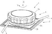
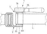
도 1a, 1b는 체결기 장치의 제 1 예시적인 실시 형태의 도를 나타낸다.
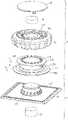
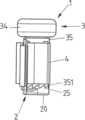
도 2a, 2b는 체결기 장치의 분해도를 나타낸다.
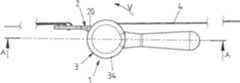
도 3a는 폐쇄 위치에 있는 체결기 장치의 사시도를 나타낸다.
도 3b는 도 3a에 따른 구성의 측면도를 나타낸다.
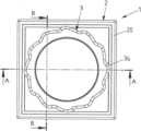
도 3c는 체결기 장치의 평면도를 나타낸다.
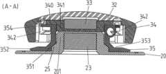
도 3d는 도 3c에 따른 A - A 선을 따른 단면도를 나타낸다.
도 3e는 도 3c에 따른 B - B 선을 따른 단면도를 나타낸다.
도 3f는 도 3e에 따른 도의 단면의 확대도를 나타낸다.
도 4a는 개방 위치에 있는 체결기 장치의 도를 나타낸다.
도 4b는 도 4a에 따른 구성의 측면도를 나타낸다.
도 4c는 체결기 장치의 평면도를 나타낸다.
도 4d는 도 4c에 따른 G - G 선을 따른 단면도를 나타낸다.
도 4e는 도 4c에 따른 I - I 선을 따른 단면도를 나타낸다.
도 4f는 도 4e에 따른 도의 일부분의 확대 상세도를 나타낸다.
도 5a는 개방 위치에 있는 체결기 장치의 평면도를 나타낸다.
도 5b는 도 5a에 따른 Q - Q 선을 따른 단면도를 나타낸다.
도 5c는 도 5b에 따른 도의 일부분의 확대 상세도를 나타낸다.
도 6a, 6b는 체결기 장치의 추가의 예시적인 실시 형태의 분해도를 나타낸다.
도 7a는 폐쇄 위치에 있는 체결기 장치의 사시도를 나타낸다.
도 7b는 도 7a에 따른 구성의 측면도를 나타낸다.
도 7c는 체결기 장치의 평면도를 나타낸다.
도 7d는 도 7c에 따른 A - A 선을 따른 단면도를 나타낸다.
도 8a는 한 체결기 부분이 다른 체결기 부분에 대해 회전하는 동안에 체결기 장치의 사시도를 나타낸다.
도 8b는 도 8a에 따른 구성의 측면도를 나타낸다.
도 8c는 체결기 장치의 평면도를 나타낸다.
도 8d는 도 8c에 따른 B - B 선을 따른 단면도를 나타낸다.
도 9a는 개방 과정 동안에 체결기 장치의 사시도를 나타낸다.
도 9b는 도 9a에 따른 구성의 측면도를 나타낸다.
도 9c는 체결기 장치의 평면도를 나타낸다.
도 9d는 도 9c에 있는 C - C 선을 따른 단면도를 나타낸다.
도 10a는 개방된 위치에 있는 체결기 장치의 사시도를 나타낸다.
도 10b는 도 10a에 따른 도의 측면도를 나타낸다.
도 10c는 체결기 장치의 평면도를 나타낸다.
도 10d는 도 10c에 있는 D - D 선을 따른 단면도를 나타낸다.
도 11a는 체결기 장치의 폐쇄 위치에 있는, 체결기 장치의 추가의 예시적인 실시 형태의 사시도를 나타낸다.
도 11b는 도 11a에 따른 구성의 측면도를 나타낸다.
도 11c는 체결기 장치의 평면도를 나타낸다.
도 11d는 도 11c에 있는 A - A 선을 따른 단면도를 나타낸다.
도 11e는 도 11c에 따른 A - A 선을 따른 수정된 예시적인 실시 형태의 단면도를 나타낸다.
도 12a는 치형부 수단의 예시적인 실시 형태의 개략도를 나타낸다.
도 12b는 도 12a에 따른 치형부 수단의 사시도를 나타낸다.
도 13a는 치형부 수단의 다른 예시적인 실시 형태의 개략도를 나타낸다.
도 13b는 도 13a에 따른 치형부 수단의 사시도를 나타낸다.
도 14a는 치형부 수단의 또 다른 예시적인 실시 형태의 개략도를 나타낸다.
도 14b는 도 14a에 따른 치형부 수단의 사시도를 나타낸다.
도 15a는 치형부 수단의 또 다른 예시적인 실시 형태의 개략도를 나타낸다.
도 15b는 도 15a에 따른 치형부 수단의 사시도를 나타낸다.
도 16a는 치형부 수단의 또 다른 예시적인 실시 형태의 개략도를 나타낸다.
도 16b는 도 16a에 따른 치형부 수단의 사시도를 나타낸다.
도 17a는 체결기 장치의 예시적인 실시 형태의 도를 나타내며, 특히 제 1 체결기 부분에 있는 치형부 수단을 도시한다.
도 17b는 도 17a에 따른 예시적인 실시 형태의 도를 나타내며, 제 2 체결기 부분에 있는 치형부 수단을 도시한다.
도 17c는 체결기 장치의 평면도를 나타낸다.
도 17d는 도 17c에 따른 A - A 선을 따른 단면도를 나타낸다.
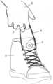
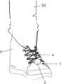
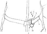
도 18은 신발을 조이기 위한 체결기 장치의 용례의 예시적인 실시 형태의 도를 나타낸다.
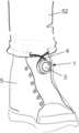
도 19는 신발을 조이기 위한 체결기 장치의 용례의 다른 예시적인 실시 형태의 도를 나타낸다.
도 20은 신발을 조이기 위한 체결기 장치의 용례의 또 다른 예시적인 실시 형태의 도를 나타낸다.
도 21은 신발의 조임 동안에 도 20에 따른 예시적인 실시 형태의 도를 나타낸다.
도 22는 신발을 조이기 위한 체결기 장치의 용례의 또 다른 예시적인 실시 형태의 도를 나타낸다.
도 23은 신발을 조이기 위한 체결기 장치의 용례의 또 다른 예시적인 실시 형태의 도를 나타낸다.
도 24는 신발을 조이기 위한 체결기 장치의 용례의 또 다른 예시적인 실시 형태의 도를 나타낸다.
도 25는 바지 다리를 조이기 위한 체결기 장치의 예시적인 실시 형태의 도를 나타낸다.
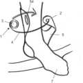
도 26은 바지 다리를 신발과 함께 지탱시키기 위한 체결기 장치의 용례의 예시적인 실시 형태의 도를 나타낸다.
도 27은 바지 다리를 신발에 조이기 위한 체결기 장치의 용례의 다른 예시적인 실시 형태의 도를 나타낸다.
도 28은 옷을 폐쇄하기 위한 체결기 장치의 용례의 예시적인 실시 형태의 도를 나타낸다.
도 29는 폐쇄된 옷의 경우에 도 28에 따른 예시적인 실시 형태의 도를 나타낸다.
도 30은 옷을 폐쇄하기 위한 체결기 장치의 용례의 다른 예시적인 실시 형태의 도를 나타낸다.
도 31은 의료 보조물을 폐쇄하고 조이기 위한 체결기 장치의 용례의 예시적인 실시 형태의 도를 나타낸다.
도 32는 폐쇄되고 조여진 상태에 있는, 도 31에 따른 예시적인 실시 형태의 도를 나타낸다.
도 33은 의료 보조물을 폐쇄하고 조이기 위한 체결기 장치의 용례의 다른 예시적인 실시 형태의 도를 나타낸다.
도 34는 폐쇄된 상태에 있는 도 33에 따른 예시적인 실시 형태의 도를 나타낸다.
도 35는 다른 의료 보조물을 폐쇄하고 조이기 위한 체결기 장치의 용례의 예시적인 실시 형태의 도를 나타낸다.
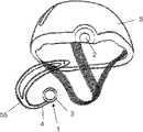
도 36은 헬멧의 벨트를 폐쇄하고 조이기 위한 체결기 장치의 용례의 예시적인 실시 형태의 도를 나타낸다.
도 37은 폐쇄된 벨트의 경우에 도 36에 따른 예시적인 실시 형태의 도를 나타낸다.
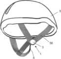
도 38은 헬멧의 끈을 폐쇄하고 조이기 위한 체결기 장치의 용례의 예시적인 실시 형태의 도를 나타낸다.
도 39는 폐쇄된 끈의 경우에 도 38에 따른 예시적인 실시 형태의 도를 나타낸다.
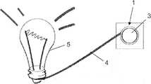
도 40은 램프를 걸기 위한 체결기 장치의 용례의 예시적인 실시 형태의 도를 나타낸다.
도 41은 그림을 걸기 위한 체결기 장치의 용례의 예시적인 실시 형태의 도를 나타낸다.
도 42는 램프를 플러그 소켓에 연결하기 위한 체결기 장치의 용례의 예시적인 실시 형태의 도를 나타낸다.
도 43은 플러그 소켓에 연결되는 도 42에 따른 예시적인 실시 형태의 도를 나타낸다.
도 44는 인장된 케이블의 경우에 도 43에 따른 예시적인 실시 형태의 도를 나타낸다.
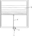
도 45는 롤러 블라인드를 인장시키기 위한 체결기 장치의 용례의 예시적인 실시 형태의 도를 나타낸다.
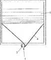
도 46은 롤러 블라인드를 인장시키기 위한 체결기 장치의 용례의 다른 예시적인 실시 형태의 도를 나타낸다.
도 47은 가방에 있는 스트랩을 조이기 위한 체결기 장치의 용례의 예시적인 실시 형태의 도를 나타낸다.
도 48은 배낭에 있는 인장 요소를 조이기 위한 체결기 장치의 용례의 예시적인 실시 형태의 도를 나타낸다.
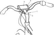
도 49는 자전거에 물품을 고정시키기 위한 체결기 장치의 용례의 예시적인 실시 형태의 도를 나타낸다.
도 50은 자전거에 물품을 고정시키기 위한 체결기 장치의 용례의 다른 예시적인 실시 형태의 도를 나타낸다.
도 51은 물품을 차량의 화물 격실에 고정시키기 위한 체결기 장치의 용례의 예시적인 실시 형태의 도를 나타낸다.
도 52는 스트랩 형태의 인장 요소를 갖는 체결기 장치의 추가의 예시적인 실시 형태의 도를 나타낸다.
도 53은 도 52에 따른 체결기 장치의 정면도를 나타낸다.
도 54는 체결기 장치의 측면도를 나타낸다.
도 55는 체결기 장치의 평면도를 나타낸다.
도 56은 도 55에 따른 A - A 선을 따른 단면도를 나타낸다.
도 57a는 2개의 스트랩 단부를 함께 연결하기 위한 체결기 장치의 도를 나타낸다.
도 57b는 폐쇄된 상태에 있는 체결기 장치의 도를 나타낸다.
도 58은 체결기 장치의 다른 예시적인 실시 형태의 도를 나타낸다.
도 59는 2개의 스트랩 단부를 함께 연결하기 위한 체결기 장치의 추가의 예시적인 실시 형태의 도를 나타낸다.
도 60은 폐쇄 위치에 있는 체결기 장치의 도를 나타낸다.
도 61a는 체결기 장치의 평면도를 나타내고, 조임 레버가 체결기 부분들을 서로에 장착하기 위한 위치에 있다.
도 61b는 도 61a에 따른 부분 A의 확대 상세도를 나타낸다.
도 62a는 인장 요소의 조임 동안에 체결기 장치의 평면도를 나타낸다.
도 62b는 도 62a에 따른 부분 A의 확대 상세도를 나타낸다.1a, 1b show a diagram of a first exemplary embodiment of a fastener device.
2a, 2b show an exploded view of the fastener device.
3A shows a perspective view of the fastener device in a closed position.
Fig. 3b shows a side view of the arrangement according to Fig. 3a;
3c shows a plan view of the fastener device.
Figure 3d shows a cross-sectional view along line A - A according to Figure 3c.
Figure 3e shows a cross-sectional view along line B - B according to Figure 3c.
Fig. 3f shows an enlarged view of the cross-section of the diagram according to Fig. 3e;
4A shows a view of the fastener device in an open position.
Fig. 4b shows a side view of the arrangement according to Fig. 4a;
4C shows a plan view of the fastener device.
Figure 4d shows a cross-sectional view along the line G-G according to Figure 4c.
Figure 4e shows a cross-sectional view along the line I - I according to Figure 4c.
Fig. 4f shows an enlarged detail view of a portion of the diagram according to Fig. 4e;
5A shows a plan view of the fastener device in an open position.
Figure 5b shows a cross-sectional view along the line Q-Q according to Figure 5a.
Fig. 5c shows an enlarged detail view of a portion of the diagram according to Fig. 5b;
6a, 6b show an exploded view of a further exemplary embodiment of a fastener device.
7A shows a perspective view of the fastener device in a closed position.
Fig. 7b shows a side view of the arrangement according to Fig. 7a;
7c shows a plan view of the fastener device.
Fig. 7d is a cross-sectional view taken along the line A - A according to Fig. 7c.
8A shows a perspective view of the fastener device during rotation of one fastener portion relative to the other fastener portion.
Fig. 8b shows a side view of the arrangement according to Fig. 8a;
8C shows a plan view of the fastener device.
Fig. 8d is a cross-sectional view taken along line B - B according to Fig. 8c.
9A shows a perspective view of the fastener device during an opening process.
Fig. 9b shows a side view of the arrangement according to Fig. 9a;
9C shows a plan view of the fastener device.
Figure 9d shows a cross-sectional view taken along line C - C in Figure 9c.
10A shows a perspective view of the fastener device in an open position.
Fig. 10b shows a side view of the diagram according to Fig. 10a;
10C shows a plan view of the fastener device.
Fig. 10d is a cross-sectional view taken along the line D - D in Fig. 10c.
11A shows a perspective view of a further exemplary embodiment of the fastener device, in its closed position, FIG.
Fig. 11b shows a side view of the arrangement according to Fig. 11a;
11C shows a plan view of the fastener device.
Fig. 11d is a cross-sectional view taken along the line A - A in Fig. 11c.
11e shows a cross-sectional view of the modified exemplary embodiment along the line A-A according to FIG. 11c.
12a shows a schematic diagram of an exemplary embodiment of a tooth means.
Fig. 12b shows a perspective view of the tooth means according to Fig. 12a;
13a shows a schematic diagram of another exemplary embodiment of a tooth means.
Fig. 13b shows a perspective view of the tooth means according to Fig. 13a;
14a shows a schematic diagram of another exemplary embodiment of a tooth means.
Fig. 14b shows a perspective view of the tooth means according to Fig. 14a;
15a shows a schematic diagram of another exemplary embodiment of a tooth means.
Fig. 15b shows a perspective view of the tooth means according to Fig. 15a;
16a shows a schematic diagram of another exemplary embodiment of a tooth means.
Fig. 16b shows a perspective view of the tooth means according to Fig. 16a;
Fig. 17a shows a view of an exemplary embodiment of a fastener device, in particular showing the tooth means in the first fastener part.
Fig. 17b shows a view of the exemplary embodiment according to Fig. 17a, showing the tooth means in the second fastener part;
17C shows a plan view of the fastener device.
Fig. 17d shows a cross-sectional view along the line A - A according to Fig. 17c.
18 shows a diagram of an exemplary embodiment of application of a fastener device for fastening a shoe.
19 shows a diagram of another exemplary embodiment of application of a fastener device for fastening a shoe.
20 shows a diagram of another exemplary embodiment of application of a fastener device for fastening a shoe.
21 shows a view of the exemplary embodiment according to FIG. 20 during tightening of a shoe.
22 shows a diagram of another exemplary embodiment of application of a fastener device for fastening a shoe.
23 shows a diagram of another exemplary embodiment of application of a fastener device for fastening a shoe.
24 shows a diagram of another exemplary embodiment of application of a fastener device for fastening a shoe.
25 shows a diagram of an exemplary embodiment of a fastener device for tightening a trouser leg.
26 shows a diagram of an exemplary embodiment of application of a fastener device for holding a pant leg together with a shoe.
27 shows a diagram of another exemplary embodiment of application of a fastener device for tightening a pant leg to a shoe.
28 shows a diagram of an exemplary embodiment of application of a fastener device for closure of clothing.
29 shows a view of the exemplary embodiment according to FIG. 28 in the case of closed clothing.
30 shows a diagram of another exemplary embodiment of application of a fastener device for closure of clothing.
31 shows a diagram of an exemplary embodiment of application of a fastener device for closing and tightening a medical aid.
32 shows a view of the exemplary embodiment according to FIG. 31 in a closed and screwed state;
33 shows a diagram of another exemplary embodiment of application of a fastener device for closing and tightening a medical aid.
34 shows a view of the exemplary embodiment according to FIG. 33 in a closed state.
35 depicts an illustration of an exemplary embodiment of application of a fastener device for closing and tightening another medical aid.
36 shows a diagram of an exemplary embodiment of application of a fastener device for closing and tightening a belt of a helmet.
37 shows a diagram of an exemplary embodiment according to FIG. 36 in the case of a closed belt;
38 shows a diagram of an exemplary embodiment of application of a fastener device for closing and tightening the straps of a helmet.
39 shows a diagram of an exemplary embodiment according to FIG. 38 in the case of a closed strap;
40 shows a diagram of an exemplary embodiment of application of a fastener device for hanging a lamp.
41 shows a diagram of an exemplary embodiment of application of a fastener device for hanging pictures.
42 shows a diagram of an exemplary embodiment of application of a fastener device for connecting a lamp to a plug socket.
43 shows a diagram of the exemplary embodiment according to FIG. 42 connected to a plug socket;
44 shows a diagram of an exemplary embodiment according to FIG. 43 in the case of a tensioned cable.
45 shows a diagram of an exemplary embodiment of application of a fastener device for tensioning a roller blind.
46 shows a diagram of another exemplary embodiment of application of a fastener device for tensioning a roller blind.
47 shows a diagram of an exemplary embodiment of application of a fastener device for tightening a strap in a bag.
48 shows a diagram of an exemplary embodiment of application of a fastener device for tightening a tensioning element in a backpack.
49 shows a diagram of an exemplary embodiment of application of a fastener device for securing an article to a bicycle.
50 shows a diagram of another exemplary embodiment of application of a fastener device for securing an article to a bicycle.
51 shows a diagram of an exemplary embodiment of application of a fastener device for securing an article to a cargo compartment of a vehicle.
52 shows a diagram of a further exemplary embodiment of a fastener device having a tension element in the form of a strap.
Fig. 53 shows a front view of the fastener device according to Fig. 52;
54 shows a side view of the fastener device.
55 shows a plan view of the fastener device.
56 shows a cross-sectional view along line A-A according to FIG. 55;
57A shows a view of a fastener device for connecting two strap ends together.
57B shows a view of the fastener device in a closed state.
58 shows a diagram of another exemplary embodiment of a fastener device.
59 shows a view of a further exemplary embodiment of a fastener device for connecting two strap ends together.
60 shows a view of the fastener device in a closed position.
61A shows a plan view of the fastener device, with the tightening lever in position for mounting the fastener parts to each other.
Fig. 61b shows an enlarged detail of part A according to Fig. 61a;
62A shows a plan view of the fastener device during tightening of the tensioning element.
Fig. 62b shows an enlarged detail of part A according to Fig. 62a.
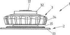
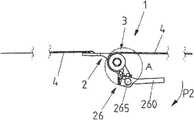
도 1a, 1b 내지 도 5a - 5c는 체결기 장치(1)의 예시적인 실시 형태를 나타내고, 이 체결기 장치에서 체결기 부분(2, 3)이 폐쇄 방향(X)을 따라 서로에 장착될 수 있고 폐쇄 위치에서 서로에 유지된다.1a , 1b to 5a - 5c show an exemplary embodiment of a
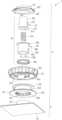
도 2a 및 2b에 따른 분해도로부터 알 수 있는 바와 같이, 제 1 체결기 부분(2)은 원통형 부분(201)이 형성되는 본체(20)를 갖는다. 치형부(25)가 원통형 부분(201) 주위에 에워싸는 방식으로 연장되어 있고, 그 치형부의 치부는 톱니형을 갖는다. 자석 요소(23)가 또한 본체(20)에 배치된다.As can be seen from the exploded view according to FIGS. 2a and 2b , the
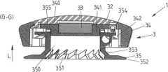
제 2 체결기 부분(3)은 핸드그립 형태의 작동 요소(34), 및 채널(353)을 형성하는 권취 요소(35)를 가지며, 그 채널의 경계는 축방향으로 환형 칼라(352, 354)에 의해 한정되며, 인장 요소(4)가 권취 요소(35) 상에 감기기 위해 채널에 수용될 수 있다. 작동 요소(34)에는 자석 요소(33)가 고정되며, 이 자석 요소는 자기적 인력 작용으로 제 1 체결기 부분(2)에 있는 자석 요소(23)와 상호 작용한다.The
제 1 체결기 부분(2) 쪽을 향하는 측에서 치형부(351)가 권취 요소(35)에 형성되어 있다. 도 3a - 3f에 도시되어 있는 바와 같이, 체결기 부분(2, 3)이 서로에 장착되는 동안에, 권취 요소(35)의 치형부(351)가 제 1 체결기 부분(2)의 본체(20)에 있는 치형부(25)와 결합한다.On the side towards the
체결기 부분(2, 3)이 서로에 장착되면, 원통형 부분(201)이 권취 요소(35)의 중심 개구(350)에 결합하고, 따라서 그에 의해 권취 요소(35)는 회전 가능하게 또한 축선 방향으로 움직일 수 있게 제 1 체결기 부분(2)에 장착된다.When the
권취 요소(35)의 치형부(351)와 제 1 체결기 부분(2)의 치형부(25)는 톱니형을 갖는다. 이리하여, 체결기 장치(1)의 폐쇄 위치에서, 권취 요소(35)와 작동 요소(34)를 갖는 제 2 체결기 부분(3)이 권취 방향(V)으로 제 1 체결기 부분(2)에 대해 회전될 수 있고, 치형부(25, 351)의 치부는 서로의 상에서 슬라이딩하며 또한 서로의 위에서 움직일 수 있고, 체결기 부분(2, 3)은 서로에 대해 축선 방향으로 편향된다. 따라서, 치형부(25, 351)는 일종의 프리휠을 제공하는데, 체결기 부분(2, 3)이 서로에 장착되면, 권취 요소(35)에 배치되는 인장 요소(4)가 조여지도록 프리휠은 권취 방향(V)으로의 권취 요소(35)의 회전을 허용하고 하지만 권취 방향(V)의 반대 방향의 움직임은 억제하며, 그래서 체결기 부분(2, 3)이 서로에 장착된 상태에서 인장 요소(4)는 권취 방향(V)의 반대 방향으로 풀리지 못한다.The
예컨대 도 3e 및 3f에서 알 수 있는 바와 같이, 치형부(25, 351)의 치부 각각은 언더컷을 형성하고, 체결기 부분(2, 3)이 하중을 받을 때, 치형부(25, 351)는 권취 방향(V)의 반대 방향으로 잠금 작용으로 서로 결합하며, 그래서 권취 요소(35)가 권취 방향(V)의 반대 방향으로 제 1 체결기 부분(2)에 대해 회전하는 것이 방지된다. 결합은, 치형부(25, 351)의 언더컷 치부 플랭크(하중이 권취 방향(V)의 반대 방향으로 작용할 때 상호 작용함) 때문에, 회전 공동적이고 하중 지탱적이며 또한 자기 강화적(self-intensifying)이다.As can be seen, for example in FIGS. 3E and 3F, each of the teeth of the
권취 요소(35)는 회전 가능하게 작동 요소(34)에 장착되고, 이러한 목적으로, 작동 요소(34)에 회전 가능하게 유지되며, 또한 유지 요소(342)에 의해 폐쇄 방향(X)을 따라 변위 이동으로 축선 방향으로 변위 가능하고, 유지 요소는 환형 칼라(354)에 결합하고 작동 요소(34)의 기부 표면(340)으로부터 내측으로 돌출해 있다. 유지 요소(342)는 환형 칼라(354) 주위에 결합하여, 권취 요소(35)와 작동 요소(34) 사이의 연결을 생성한다.The winding
권취 요소(35)가 위치에 무관하게 작동 요소(34)와 함께 또는 작동 요소(34)와는 독립적으로 움직일 수 있도록, 작동 요소(34) 및 권취 요소(35)는 또한 결합 수단(345, 355)에 의해 결합 가능하다. 이 경우, 제 1 결합 수단(345)은 폐쇄 방향(X) 주위에 원주 방향으로 일 열로 정렬되어 있는 개구들의 형태로 기부 표면(340)에 형성되며, 그 개구들은 제 2 결합 수단(355)과 작동 연결될 수 있고, 제 2 결합 수단은 환형 칼라(354)에 형성되고 환형 칼라(354)로부터 축선 방향으로 돌출하며, 그리하여, 힘이 권취 방향(V)으로 전달되도록 작동 요소(34)가 권취 요소(35)에 연결된다.The
작동 요소(34)에는 커버 요소(32)가 배치되어 있고, 이 커버 요소는 권취 요소(35)로부터 멀어지는 측에서 작동 요소(34)를 폐쇄하며 이러한 목적으로 멈춤쇠작용으로 작동 요소(34)와 결합하게 된다.A
작동 요소(34)는 원주 방향 측벽(344)으로 수용 공간을 에워싸고, 이 수용 공간 내부에는 권취 요소(35)가 환형 칼라(354)에 의해 수용되고 또한 축선 방향으로 변위 가능하게 유지된다. 여기서, 원통형 돌출부(341)가 기부 표면(340)으로부터 중심에서 돌출해 있고, 그 원통형 돌출부는 권취 요소(35)의 중심 개구(350) 안으로 결합하고 그리하여 작동 요소(34)와 권취 요소(35)를 폐쇄 방향(X) 주위에 회전 가능하게 서로에 장착하는 역할을 한다.The
체결기 부분(2, 3)이 서로에 장착되는 동안에, 자석 요소(23, 33)의 자기적 인력 상호 작용 때문에, 권취 요소(35)의 개구(350)의 내측면에 있는 치형부(351)는 원통형 부분(201) 주위에 있는 치형부(25)와 결합하고, 도 3a 내지 3f에 도시되어 있는 바와 같이, 그 원통형 부분은 권취 요소(35)의 개구(350)와 결합한다. 자석 요소(23, 33)의 자기적 인력에 의해 작동 요소(34)가 제 1 체결기 부분(2)의 본체(20)의 원통형 부분(201) 쪽으로 끌어 당겨지고 그래서 그의 기부 표면(340)으로 권취 요소(35)의 환형 칼라(354)에 더 가까워지게 움직이기 때문에, 작동 요소(34) 및 권취 요소(35)의 결합 수단(345, 355)은 서로 결합하여, 도 3d 내지 3f의 단면도에 도시되어 있는 바와 같이, 작동 요소(34)와 권취 요소(35)가 서로 기능적 작동 연결된다.
폐쇄 위치에서 작동 요소(34) 및 권취 요소(35) 사이에 이루어지는 작동 연결 때문에, 작동 요소(34)가 권취 방향(V)으로 회전하는 경우에, 권취 요소(35)는 작동 요소(34)와 함께 움직여 폐쇄 방향(X) 주위로 회전되는데, 작동력이 결합 수단(345, 355)의 결합에 의해 권취 요소(35)에 전달되기 때문이다. 여기서, 치형부(25, 351)는 서로의 위에서 슬라이딩하며, 그래서 권취 요소(35)는 제 1 체결기 부분(2)에 대해 회전되어 인장 요소(4)가 권취 요소(35) 상으로 감기게 된다.Owing to the working connection made between the actuating
치형부(25, 351)의 톱니형 언더컷 형태 때문에, 권취 방향(V)의 반대 방향으로 인장 요소(4)에 의해 도입되는 하중으로 인해 권취 요소(35)가 역방향으로 회전하는 일이 생기지 않는다. 이는 치형부(25, 351)가 서로에 결합함으로써 방지된다.Because of the serrated undercut shape of the
특히 도 3e 내지 3f의 단면도에서 알 수 있는 바와 같이, 권취 요소(35)의 결합 수단(355)은 톱니형이고, 톱니형 치부는 경사진 치부 플랭크 및 대략 수직인 치부 플랭크를 갖는다. 이 톱니형 치형부(355)는, 결합 위치에서, 작동 요소(34)의 기부 표면(340)에 있는 개구(결합 수단(345)을 형성함)에 결합하며, 이 결합은, 권취 방향(V)의 작동력이 작동 요소(34)로부터 권취 요소(35)에 전달되도록 되어 있고, 따라서 권취 요소(35)는 작동 요소(34)와 함께 권취 방향(V)으로 움직이지만, 작동 요소(34)가 권취 방향(V)의 2,3반대 방향으로 회전하는 경우에는, 결합 수단(345, 355)은 서로의 위에서 슬라이딩할 수 있고 그래서 작동 요소(34)가 권취 방향(V)의 반대 방향으로 권취 요소(35)에 대해 상대적으로 움직일 수 있다.As can be seen in particular from the cross-sectional views of FIGS. 3e to 3f , the engaging means 355 of the winding
도 4a 내지 4f에 도시되어 있는 바와 같이, 체결기 부분(2, 3)을 서로로부터 해제시키고자 하면, 제 2 체결기 부분(3)은 폐쇄 방향(X)의 반대 방향으로 해제 방향(L)으로 제 1 체결기 부분(2)으로부터 간단히 끌어 당겨져 떨어질 수 있고, 그리하여, 치형부(25, 351)가 서로로부터 결합 해제되고 체결기 부분(2, 3)이 서로로부터 해제된다.As shown in Figs. 4a to 4f, when it is desired to release the
이 경우 자석 요소(23, 33) 사이의 자기적 인력이 제거되기 때문에, 결합 수단(345, 355)은 서로로부터 결합 해제되고, 따라서 권취 요소(35)는 작동 요소(34)와는 독립적으로 회전될 수 있다. 이리하여, 체결기 장치(1)가 개방 상태에서, 예컨대, 권취 요소(35)에 배치되어 있는 인장 요소(4)가 자유롭게 풀릴 수 있다.Since in this case the magnetic attraction between the
그리하여, 작동 요소(34)와 권취 요소(35)의 결합 수단(345, 355)은 예컨대 중력의 작용 때문에 체결 장치(1)의 개방 동안에 결합 해제된다. 그러나, 한 유리한 실시 형태에서, 도 5a 내지 5c에 도시되어 있는 바와 같이, 기부 표면(340)의 내측면에 배치되어 있고 도시된 예시적인 실시 형태에서 일체적으로 형성된 스프링 돌출부로 형성되는 스프링 요소(343)에 의해, 작동 요소(34)는 해제 위치의 방향으로 권취 요소(35)에 대해 스프링 예압을 받으며, 해제 위치에서 결합 수단(345, 355)은 서로 결합하지 않으며, 그래서 작동 요소(34)와 권취 요소(35)는 체결기 장치(1)의 개방 동안에 자동적으로 또한 신뢰적으로 서로 결합 해제되어, 체결기 장치(1)가 개방된 상태에서 권취 요소(35)가 작동 요소(34)와는 독립적으로 회전될 수 있다.Thus, the engaging means 345 , 355 of the
도 6a, 6b 내지 10a - 10d는 다른 예시적인 실시 형태를 나타내며, 이 실시 형태는, 제 1 체결기 부분(2)과 권취 요소(35) 사이에 작용하는 치형부(25, 351)에 대해 또한 권취 요소(35)와 제 2 체결기 부분(3)의 작동 요소(34) 사이에 작용하는 결합 수단(345, 355)에 대해, 도 1a, 1b 내지 5a - 5f에 기반하여 전술한 예시적인 실시 형태와 동일한 설계로 되어 있고, 그래서 이와 관련해서는 전술한 바를 참조하면 된다.6a , 6b to 10a - 10d show another exemplary embodiment, which also relates to the
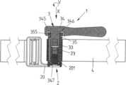
추가로, 도 6a, 6b 내지 10a - 10d에 따른 예시적인 실시 형태는 제 2 체결기 부분(3)에 배치되는 멈춤쇠 수단(36)을 가지며, 이 멈춤쇠 수단은, 제 2 체결기 부분(3)이 멈춤쇠 작용 및 폐쇄 방향(X)의 반대 방향으로 일어나는 제 1 체결기 부분(2)에 대한 포지티브 잠금 작용으로 유지되도록, 체결기 부분(2, 3)을 구속시키는 역할을 한다.In addition, the exemplary embodiment according to FIGS. 6a , 6b to 10a - 10d has a detent means 36 arranged on the
위와 같은 종류의 멈춤쇠 수단(36)을 사용함으로써 비자기적 형태의 체결기 장치(1)가 가능하게 된다. 따라서 기본적으로, 자석 요소가 체결기 장치(1)에서 생략될 수 있다. 그러나, 도 1a, 1b 내지 5a - 5f에 따른 예시적인 실시 형태에 존재하는 바와 같은 자석 요소가 멈춤쇠 수단(36)에 추가로 사용되는 것도 가능하다.The use of detent means 36 of the above kind makes possible the
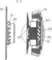
멈춤쇠 수단(36)은 결합 요소(38)을 가지며, 도 7d와 함께 도 6b에서 알 수 있는 바와 같이, 이 결합 수단은 환형 칼라(381)로, 작동 요소(34)에 장착되는 커버 요소(32) 내의 수용 공간(322)에 축선 방향으로 움직일 수 있게 수용되며, 또한 나선 스프링 형태의 스프링 요소(384)에 의해 작동 요소(34)의 기부 표면(340)에 대해 스프링 예압을 받는다. 환형 칼라(381)로부터 연장되어 있는 원통체(380)에는 수용 개구(382)들이 서로 정반대편에 형성되어 있고, 이 수용 개구에는 볼 형태의 멈춤쇠 요소(385)가 수용되며, 이 요소는 체결기 장치(1)의 폐쇄 위치(도 7a 내지 7d)에서, 제 1 체결기 부분(2)의 원통형 부분(201)의 개구(200)의 내측면에 에워싸는 방식으로 연장되어 있는 환형 홈의 형태로 된 멈춤쇠 오목부(202)에 멈춤쇠 작용으로 결합하고, 그래서, 도 7d에서 알 수 있는 바와 같이, 그에 의해, 결합 요소(38)(폐쇄 위치에서 원통형 부분(201)의 개구(200)에 결합함)와 원통형 부분(201) 사이에 멈춤쇠 결합이 있으며, 이에 의해 체결기 부분(2, 3)이 함께 구속된다.The detent means 36 has a
결합 요소(38)의 중심 개구(383) 내부에서, 작동 요소(37)가 폐쇄 방향(X)을 따라 축선 방향으로 안내된다. 작동 요소(37)는 원통형 설계를 가지며, 폐쇄 위치에서, 블라인드 보어 형태의 개구(373)에 위치되는 스프링 요소(374)에 의해 제 1 체결기 부분(2)에 탄성적으로 지지되며, 또한, 작동 요소가 결합 요소(38)에 대해 작동되지 않을 때, 단부측에 있는 환형 칼라(371)에 의해 이동 제한 방식으로 결합 요소(38)와 접촉한다.Inside the
도 7d와 함께 도 6a, 6b에서 알 수 있는 바와 같이, 따라서 작동 요소(37)는, 그의 외주 표면에서, 서로 정반대편에 위치하는 2개의 잠금해제 개구(372)를 가지며, 도 7d에서 알 수 있는 바와 같이, 폐쇄 위치에서 이들 감금해제 개구는 멈춤쇠 요소(385)에 대해 축선 방향으로 다른 높이에 배치되며, 그래서 멈춤쇠 요소(385)는 작동 요소(37)의 원통체(370)의 외주 표면과 접촉하고, 그에 의해 원통형 부분(201)의 내측면에 있는 멈춤쇠 오목부(202)와 멈춤쇠 결합하여 유지된다.As can be seen from FIGS. 6a , 6b together with FIG. 7d , the
폐쇄 위치(도 7a - 7d)에서, 스프링 요소(384)의 스프링 예압 때문에, 작동 요소(34)는 제 1 체결기 부분(2)의 방향으로 밀리고, 또한 기부 표면(240)이 권취 요소(35)의 환형 칼라(354)에 접촉하기 때문에, 도 7d에서 알 수 있는 바와 같이, 권취 요소(35)가 밀려 제 1 체결기 부분(2)의 치형부(25)와 결합하게 된다. 그래서, 폐쇄 위치에서, 제 2 체결기 부분(3)은, 제 1 체결기 부분(2)에 대한 멈춤쇠 작용, 작동 요소(34)와 권취 요소(35)의 결합 수단(345, 355) 사이의 기존의 결합, 및 추가적으로 권취 요소(35)와 제 1 체결기 부분(2) 사이의 치형부 결합으로 유지된다.In the closed position ( FIGS. 7a - 7d ), because of the spring preload of the
체결기 장치(1)의 폐쇄 위치에서, 결합 수단(345, 355)의 결합에 의해 작동 요소(34) 및 권취 요소(35)가 작동 요소(34)와 함께 권취 방향(V)으로 회전되면, 치형부(25, 351)가 서로의 위에서 슬라이딩하고, 그리하여, 도 8a - 8d에 도시되어 있는 바와 같이, 권취 요소(35)의 (작은) 축선방향 움직임이 일어나고 또한 이에 의해 작동 요소(34)의 축선방향 움직임이 일어나게 된다. 여기서, 멈춤쇠 수단(36)의 결합 요소(38)는 멈춤쇠 요소(385)에 의해 제 1 체결기 부분(2)의 원통형 부분(201)에 대해 축선방향으로 고정되어 유지되기 때문에, 도 8d에 도시되어 있는 바와 같이, 권취 요소(35)와 작동 요소(34)의 축선방향 편향은 스프링 요소(384)의 스프링 예압에 대항하여 일어난다.In the closed position of the
작동 요소(34)와 권취 요소(35)의 회전 후에, 스프링 요소(384)의 스프링 예압으로 인해 치형부(25, 351)가 서로 다시 결합하게 되며, 이때 환형 칼라(352)는 제 1 체결기 부분(2)의 본체(20)에 접촉한다(도 7a 내지 7d에 따른 위치에 대응하여).After the rotation of the
체결기 부분(2, 3)을 서로 해제시키기 위해, 도 9a 내지 9d에 도시되어 있는 바와 같이, 사용자는 작동 요소(37)를 결합 요소(38) 안으로 작동 방향(D)으로 밀 수 있다. 이렇게 해서, 작동 요소(37)의 본체(370)는 결합 요소(38) 내부에서 폐쇄 방향(X)을 따라 축선방향으로 조절되어, 잠금해제 개구(372)가 멈춤쇠 요소(385)와 동일한 축선방향 높이로 이동하고 그래서, 도 9d에 도시되어 있는 바와 같이, 멈춤쇠 요소(385)가 반경방향 내측으로 편향될 수 있다. 이렇게 해서, 결합 요소(38)와 원통형 부분(201) 사이의 잠금 멈춤쇠 결합이 없어져, 체결기 부분(2, 3)이 폐쇄 방향(X)의 반대 방향으로, 즉 해제 방향(L)으로 서로로부터 제거될 수 있다.To release the
도 10a 내지 10d는 개방 위치에 있는 체결기 장치(1)를 나타낸다. 개방 위치에서, 체결기 부분(2, 3)은 서로 분리되고, 중력의 작용 또는 스프링 예압에 의해, 결합 수단(345, 355)을 갖는 작동 요소(34) 및 권취 요소(35)가 결합 해제되어, 권취 요소(35)가 작동 요소(34)와는 독립적으로 회전될 수 있고 그래서 권취 요소(35)에 배치되어 있는 인장 요소가 풀릴 수 있다.10a to 10d show the
체결기 장치(1)를 다시 폐쇄하기 위해, 제 2 체결기 부분(3)이 폐쇄 방향(X)으로 제 1 체결기 부분(2) 상에 다시 장착될 수 있고, 그리하여, 결합 요소(38)는 원통형 부분(201)의 개구(200)와 결합하고 멈춤쇠 요소(385)는 멈춤쇠 작용으로, 원통형 부분(201) 내의 환형 홈의 형태로 있는 멈춤쇠 오목부(202)에 결합하게 된다. 이렇게 해서, 치형부(25, 351)가 또한 서로 치형부 결합하게 되며, 체결기 장치(1)는 도 7a 내지 7d에 도시된 폐쇄 위치에 있게 된다.To close the
도 11a 내지 11e는, 한편으로 자기적으로 설계되어 있고 다른 한편으로는 비자기적으로 설계로 되어 있는, 도 6a, 6b 내지 10a - 10d에 따른 예시적인 실시 형태와 비교하여 수정된 예시적인 실시 형태를 나타낸다.11a to 11e show a modified exemplary embodiment compared to the exemplary embodiment according to FIGS. 6a , 6b to 10a - 10d, designed magnetically on the one hand and nonmagnetic on the other hand; indicate
외관적으로 볼 때, 두 예시적인 실시 형태는 유사하지만(도 11a 내지 11c 참조), 도 11d 및 11e에서 알 수 있는 바와 같이, 내부 설계 면에서는 (약간) 서로 다르다.Externally, the two exemplary embodiments are similar (see FIGS. 11A to 11C ), but differ (slightly) from each other in terms of internal design, as can be seen in FIGS. 11D and 11E .
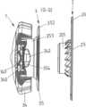
양 예시적인 실시 형태에서, 멈춤쇠 수단(36)은 결합 요소(38)를 갖는데, 이 결합 요소에는 연속적인 보어(387)가 형성되어 있고, 이 보어는 폐쇄 방향(X)에 대해 횡으로 연장되어 있고, 그 연속적인 보어에는 2개의 구형 멈춤쇠 요소(385)가 배치되고 스프링 요소(386)에 의해 서로에 대해 예압된다. 도 11d 및 11e에서 알 수 있는 바와 같이, 체결기 부분(2, 3)이 서로에 장착될 때, 결합 요소(38)는 원통형 부분(201)과 결합하고, 멈춤쇠 요소(385)는 멈춤쇠 작용으로 원통형 부분(201)의 개구(200)의 내측면에 있는 멈춤쇠 오목부(202)와 결합하게 된다.In both exemplary embodiments, the detent means 36 has a
여기서, 폐쇄 위치에서 멈춤쇠 결합은 스프링 요소(386)에 의한 스프링 예압 때문에 유지된다. 멈춤쇠 결합을 해제시키고자 하면, 충분한 힘을 가하여 제 2 체결기 부분(3)을 제 1 체결기 부분(2)에서 떨어지게 폐쇄 방향(X)의 반대 방향으로 끌어 당길 수 있고, 그리하여, 멈춤쇠 요소(385)는 자동적으로 홈형 멈춤쇠 오목부(202)의 상측 가장자리 상으로 감으로써 반경 방향 내측으로 오프셋되어 멈춤쇠 오목부(202)로부터 결합 해제된다. 그래서, 결합 요소(38)의 별도의 작동 없이 체결기 부분(2, 3) 사이의 멈춤쇠 결합이 해제될 수 있다.Here, detent engagement in the closed position is maintained due to spring preload by
도 11d에 따른 예시적인 실시 형태는 순수하게 기계적인 형태이지만, 도 11e에 따른 수정된 예시적인 실시 형태는, 도 11e의 단면도에 알 수 있는 바와 같이, 자석 요소(23)가 제 1 체결기 부분(2)의 본체(20)에 배치되고 또한 자석 요소(33)가 결합 요소(38)의 본체(380)에 배치되어 있기 때문에, 자기적 형태로 되어 있다. 그래서 체결기 부분(2, 3)은 또한 자기적으로 상호 작용하고, 이에 따라 체결기 부분(2, 3)의 장착이 용이하게 된다.The exemplary embodiment according to FIG. 11d is of a purely mechanical form, but the modified exemplary embodiment according to FIG. 11e , as can be seen in the sectional view in FIG. 11e , the
더욱이, 도 11d 및 11e에 따른 예시적인 실시 형태는 앞에서 예시적인 실시 형태와 기능적으로 동일하며, 그래서 이에 대해서는 전술한 바를 참조할 수 있다.Moreover, the exemplary embodiment according to FIGS. 11d and 11e is functionally identical to the previous exemplary embodiment, so reference can be made to the above.
전술한 예시적인 실시 형태에서, 폐쇄 위치에서 체결기 부분(2, 3) 사이에 포지티브 잠금 유지(적어도 어떤 임계 토크까지 하중을 견딜 수 있음)를 생성하기 위해, 제 1 체결기 부분(2) 및 제 2 체결기 부분(3)에 있는 치형부 수단(25, 351)은 기본적으로 매우 상이하게 설계될 수 있다.In the exemplary embodiment described above, in order to create a positive locking retention (capable of withstanding a load up to at least a certain threshold torque) between the
도 1a, 1b 내지 5a - 5c에 따른 예시적인 실시 형태에서, 치형부 수단(25, 351)에는 언더컷이 형성되어 있어, 폐쇄 위치에서 권취 요소(35)가 권취 방향(V)의 반대 방향으로 움직이는 것이 억제된다. 그러나, 이는 단지 일 예인 것으로 이해해야 하고, 도 12a, 12b 내지 16a, 16b을 기반으로 아래에서 설명하는 바와 같이, 기본적으로 다르게 구성될 수 있다,In the exemplary embodiment according to FIGS. 1a , 1b to 5a - 5c , the tooth means 25 , 351 is formed with an undercut, such that in the closed position the winding
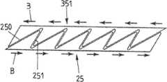
도 12a, 12b 내지 16a, 16b는, 치부의 기하학적 구조 면에서 서로 다르고 또한 여기서 설명하는 유형의 체결기 장치(1)에 사용될 수 있는 치형부 수단(25, 351)의 서로 다른 실시 형태를 나타낸다.12a , 12b to 16a , 16b show different embodiments of tooth means 25 , 351 which are different in terms of tooth geometry and which can also be used in a
따라서, 도 12a, 12b에 따른 예시적인 실시 형태에서, 각 치형부 수단(25, 351)의 치부는, 폐쇄 방향(X)에 대해 비스듬히 연장되어 있고 런-온 베벨(run-on bevel)(250)의 형태인 치부 플랭크, 및 대략 수직하게 연장되어 있고 돌출 요소(252)를 갖는 치부 플랭크(251)를 가지며, 그 돌출 요소는 상기 치부 플랭크에 형성되어 있고 권취 방향(V)을 따라 돌출해 있다. 권취 방향(V)에 반대인 하중 방향(B)으로 하중이 작용하면, 치형부 수단(25, 351)의 치부의 돌출 요소(252)들이 서로 결합하여, 하중 방향(B)(권취 방향(V)에 반대임)으로의 치형부 수단(25, 351)의 움직임이 차단된다. 따라서, 체결기 장치(1)가 폐쇄 위치에 있을 때, 권취 요소(35)는 권취 방향(V)에 반대인 하중 방향(B)으로 제 1 체결기 부분(2)에 대해 회전될 수 없다.Thus, in the exemplary embodiment according to FIGS. 12a , 12b , the tooth of each tooth means 25 , 351 extends at an angle to the closing direction X and has a run-on bevel 250 ), and a
도 12a, 12b에 따른 예시적인 실시 형태에서, 멈춤쇠 러그(253)가 치형부 수단(351)의 각 치부(또는 치부 중의 적어도 일부)의 돌출 요소(252)에 추가로 형성되어 있는데, 이 멈춤쇠 러그는, 하중 방향(B)으로 하중이 작용하는 경우에 치형부 수단(25, 351)의 치부의 잠금 결합을 추가적으로 잠그기 위해, 예컨대 멈춤쇠 작용으로 치형부 수단(25)의 관련된 치부의 돌출 요소(252)에 있는 관련된 멈춤쇠 중공부과 결합할 수 있다.In the exemplary embodiment according to FIGS. 12a , 12b , detent lugs 253 are additionally formed on the protruding
도 13a, 13b에 따른 예시적인 실시 형태는, 도 13a, 13b에 따른 예시적인 실시 형태에서는 도 12a, 12b에 따른 예시적인 실시 형태에서와 같은 멈춤쇠 러그(253)가 치형부 수단(351)의 치부의 돌출 요소(252)에 제공되어 있지 않다는 점을 제외하고는, 도 12a, 12b에 따른 예시적인 실시 형태와 동일하다.In the exemplary embodiment according to FIGS. 13a , 13b the
도 14a, 14b에 따른 예시적인 실시 형태에서, 치형부 수단(25, 351)은 톱니치형부의 형태로 되어 있다. 이 경우, 치형부 수단(25, 351)의 치부는 각 경우에 런-온 베벨(250)의 형태로 된 하나의 치부 플랭크 및 수직으로 연장되어 있는 하나의 치부 플랭크(251)를 갖는다. 치형부 수단(25, 351)이 권취 방향(V)에 반대인 하중 방향(B)으로 로딩되는 것이 억제된다.In the exemplary embodiment according to Figs. 14a, 14b, the toothed means 25, 351 is in the form of a toothed tooth. In this case, the teeth of the tooth means 25 , 351 have in each case one tooth flank in the form of a run-on
도 15a, 15b에 도시되어 있는 예시적인 실시 형태에서, 치형부 수단(25, 351)의 치부는, 도 14a, 14b에 따른 예시적인 실시 형태와 비교하여, 치부 플랭크(251)에서 언더컷되어 있는데, 즉, 폐쇄 방향(X)에 대해 비스듬히 경사져 있다. 이는 도 1a, 1b 내지 도 5a - 5c에 따른 예시적인 실시 형태에 대응한다. 치형부 장치(25, 351)가 권취 방향(V)에 반대인 하중 방향(B)으로 하중을 받는 경우, 치형부 수단(25, 351)은 서로에 대해 잠금된다.In the exemplary embodiment shown in Figs. 15a, 15b, the teeth of the tooth means 25, 351 are undercut at the tooth flanks 251 compared to the exemplary embodiment according to Figs. 14a, 14b, That is, it is obliquely inclined with respect to the closing direction X. This corresponds to the exemplary embodiment according to FIGS. 1a , 1b to 5a - 5c . When the
도 12a, 12b, 13a, 13b 및 15a, 15b에 따른 예시적인 실시 형태에서, 하중이 하중 방향(B)으로 작용하는 경우, 치형부 수단(25, 351)의 결합은 자기 부스팅(self-boosting)적이다. 따라서, 체결기 부분(2, 3)은 하중의 작용하에서 폐쇄 방향(X)으로 서로의 쪽으로 끌어 당겨지게 된다. 돌출 요소(252)에 의한 포지티브 잠금에 의해 또는 언더컷에 의해, 체결기 장치(1)는 폐쇄 방향(X)의 반대 방향으로로 개방이 안 되게 더 잠금된다. 특히, 순수하게 접선 방향으로 작용하는 것이 아니고 폐쇄 방향(X)에 반대인 성분을 가지고 작용하는 하중이 또한 수용되고 소산될 수 있다.In the exemplary embodiment according to Figs. 12a, 12b, 13a, 13b and 15a, 15b, when the load acts in the load direction B, the engagement of the tooth means 25, 351 is self-boosting. enemy Thus, the
도 16a, 16b에 따른 예시적인 실시 형태에서, 치형부 수단(25, 351)의 치부는 양 치부 플랭크(250, 251)에서 비스듬히 경사져 있어, 치부 플랭크는 런-온 베벨을 형성하고, 치형부 수단(25, 351) 사이에 충분한 힘이 작용하면, 치형부 수단(25, 351)은 권취 방향(V)으로 또한 권취 방향(V)의 반대 방향으로 서로의 위에서 슬라이딩할 수 있고, 이때 치형부 수단(25, 351)은 서로에 대해 축선방향으로 편향된다. 따라서, 도 16a, 16b에 따른 예시적인 실시 형태에서, 치형부 수단(25, 351)은 권취 방향(V)으로 또는 권취 방향(V)의 반대 방향으로 서로에 대해 잠금되지 않고, 치형부 수단(25, 351) 사이에 작용하는 토크가 충분히 높으면 라쳇(ratchet) 방식으로 서로의 위에서 슬라이딩할 수 있다.In the exemplary embodiment according to FIGS. 16a , 16b , the teeth of the tooth means 25 , 351 are inclined at both tooth flanks 250 , 251 , so that the tooth flanks form a run-on bevel, and the tooth means If sufficient force is applied between 25 and 351, the teeth means 25 and 351 can slide on top of each other in the winding direction V and in the opposite direction to the winding direction V, wherein the tooth means 25, 351 (25, 351) are axially biased with respect to each other. Thus, in the exemplary embodiment according to FIGS. 16a , 16b the teeth means 25 , 351 are not locked to each other in the winding direction V or in the direction opposite to the winding direction V, and the tooth means ( 25, 351) can slide on top of each other in a ratchet manner if the torque acting between them is high enough.
도 17a - 17d에 도시되어 있는 예시적인 실시 형태에서, 치형부 수단(25, 351)의 치부는, 원추형 기어휠의 경우 처럼, 치부 후방부에서 권취 방향(V)에 대해 또한 폐쇄 방향(X)에 대해 비스듬히 연장되어 있고, 그리하여, 하중이 권취 방향(V)의 반대 방향으로 작용하는 경우에 서로 결합하고 또한 서로에 지지되는 치형부 수단(25, 351)의 치부의 표면의 크기가 증가될 수 있다.In the exemplary embodiment shown in FIGS. 17a - 17d , the teeth of the toothed means 25 , 351 , as in the case of conical gearwheels, at the rear of the teeth, for the winding direction V and also for the closing direction X , and thus, the size of the surface of the teeth of the tooth means 25, 351 engaging with each other and supporting each other when a load acts in the opposite direction to the winding direction V can be increased. there is.
도 18 내지 51은, 전술한 유형의 예시적인 실시 형태에 따라 설계될 수 있는 체결기 장치(1)의 사용의 상이한 예시적인 실시 형태를 나타낸다.18 to 51 show different exemplary embodiments of the use of
도 18에 따른 예시적인 실시 형태에서, 체결기 장치(1)는 신발(5)을 폐쇄하고 조이는 역할을 한다. 이러한 목적으로, 체결기 부분(3)은, 신발끈 형태의 인장 요소(4)를 조이기 위해 신발(5)의 설부에 있는 체결기 부분(2) 상에 장착될 수 있다.In the exemplary embodiment according to FIG. 18 , the
도 19는 신발(5)의 다른 예시적인 실시 형태를 나타내는데, 이는 신발끈 형태의 인장 요소(4)를 감는 것에 있어서 도 18에 따른 예시적인 실시 형태와 다르다.19 shows another exemplary embodiment of a
도 18 및 19에 따른 예시적인 실시 형태에서, 신발끈 형태의 인장 요소(4)의 한 단부는, 체결기 장치(1)의 체결기 부분(3)에 고정되고, 작동 요소(34)를 권취 요소(35)와 함께 체결기 부분(2)에 대해 회전시켜 조여질 수 있다. 이 경우, 조임은, 체결기 부분(3)이 체결기 부분(2)에 고정되기 전에 체결기 부분(3)을 끌어 당겨 신발끈 형태의 인장 요소(4)를 조여 수동으로 일어날 수도 있다.In the exemplary embodiment according to FIGS. 18 and 19 , one end of the
도 20 및 21에 따른 예시적인 실시 형태에서, 신발끈 형태의 인장 요소(4)(이 경우 루프로서 감김)의 두 단부가 체결기 장치(1)의 체결기 부분(3)에 연결되며, 그래서, 체결기 부분(3)을 체결기 부분(2)에 대해 회전시키면, 신발끈 형태의 인장 요소(4)가 두 단부와 함께 감겨 조여질 수 있다. 도 21에 도시되어 있는 바와 같이, 체결기 부분(3)이 체결기 부분(2)에 배치되기 전에, 손(6)을 사용해 인장 요소(4)를 끌어 당겨 인장 요소(4)를 수동으로 조일 수 있다.In the exemplary embodiment according to FIGS. 20 and 21 , the two ends of a
도 22에 따른 예시적인 실시 형태에서, 마찬가지로, 신발끈 형태의 인장 요소(4)의 두 단부가 체결기 장치(1)의 체결기 부분(3)에 연결되며, 신발(5)을 폐쇄하여 조이기 위해, 체결기 부분(3)을 체결기 부분(2)에 대해 회전시켜 감길 수 있다. 이 경우에 신발끈 형태의 인장 요소(4)는 조임 요소(50) 주위에 놓이게 되고, 그래서, 인장 요소(4)를 체결기 부분(3)의 권취 요소(35) 상에 감아 신발(5)을 조일 수 있다.In the exemplary embodiment according to FIG. 22 , the two ends of the
도 23은 다른 예시적인 실시 형태를 나타내는데, 여기서 인장 요소(4)는 조임 요소(50) 주위에 놓여 있고, 한 단부로 체결기 장치(1)의 체결기 부분(3)에 배치되며, 그래서 체결기 장치(1)에 의해 조여질 수 있다.23 shows another exemplary embodiment, wherein the
도 24에 따른 예시적인 실시 형태에서, 신발끈 형태의 인장 요소(4)는 (또한) 신발(5)의 밑창(51) 주위에 놓여 있고, 한 단부에 의해 체결기 장치(1)의 체결기 부분(3)에 연결되어 있어, 신발(5)은 체결기 장치(1)에 의해 폐쇄되고 조여질 수 있다.In the exemplary embodiment according to FIG. 24 , the
도 25에 도시되어 있는 예시적인 실시 형태에서, 체결기 장치(1)는 밴드 형태의 인장 요소(4)로 바지 다리(52)를 신발(5)과 함께 지탱시키는 역할을 한다. 이러한 목적으로, 인장 요소(4)는 바지 다리(52) 주위에 연장되어 체결기 장치(1)에 의해 신발(5)에 고정되며, 그래서 체결기 부분(2)에 대한 체결기 부분(3)의 회전에 의해 바지 다리(52)가 신발(5)에 대해 지탱될 수 있다.In the exemplary embodiment shown in FIG. 25 , the
다른 예시적인 실시 형태가 도 26에 나타나 있다. 이 예시적인 실시 형태에서, 바지 다리(52)의 고리를 통과하는 인장 요소(4)가 체결기 장치(1)에 의해 신발(5)에 대해 지탱될 수 있기 때문에, 마찬가지로, 바지 다리(52)가 신발에 대해 지탱될 수 있다.Another exemplary embodiment is shown in FIG. 26 . In this exemplary embodiment, since the
또한, 도 27에 따른 예시적인 실시 형태에서도, 바지 다리(52)가 신발에 대해 지탱될 수 있고, 이 경우에, 인장 요소(4)는 신발(5)의 밑창(51) 주위에 밴드 형태로 연장되어 있고 체결기 장치(1)에 의해 신발(5)에 지탱될 수 있다.Also in the exemplary embodiment according to FIG. 27 , the
도 28 및 29에 따른 예시적인 실시 형태에서, 체결기 장치(1)는 옷(5), 예컨대, 조끼 또는 자켓을 폐쇄하고 조이는 역할을 한다. 밴드 또는 코드 형태의 인장 요소(4)는 옷(5)의 체결점(53)에 고정되며, 옷(5)의 개구 슬롯의 양측에 있는 조임 요소(50) 주위에 놓일 수 있고, 그리하여 도 29에 도시되어 있는 바와 같이 옷(5)을 폐쇄할 수 있다. 체결기 부분(3)이 체결기 부분(2)에 배치되고 또한 체결기 부분(3)이 체결기 부분(2)에 대해 회전됨으로써, 옷(5)이 조여질 수 있다.In the exemplary embodiment according to FIGS. 28 and 29 , the
또한, 도 30에 따른 예시적인 실시 형태에서도, 체결기 장치(1)는 옷(5)을 폐쇄하는 역할을 하는데, 이 경우, 2개의 체결기 장치(1)가 2개의 인장 요소(4)를 조이기 위해 제공되어 있다. 인장 요소(4)는 각 경우에 옷(5)의 개구 슬롯의 한측에서 체결점(53)에 고정되며, 각각의 체결기 부분(3)이 옷(5)의 개구 슬롯의 다른 에서 체결기 장치(1)의 관련된 체결기 부분(2)에 배치됨으로써 조여질 수 있다.Also in the exemplary embodiment according to FIG. 30 , the
도 31 및 32에 따른 예시적인 실시 형태에서, 체결기 장치(1)는 발목 붕대 형태의 의료용 보조물(5)을 발(7)에 폐쇄하여 조이는 역할을 한다. 발목 붕대의 한 단부에 연결되는 체결기 부분(3)이 체결기 부분(2)(발목 붕대의 다른 단부에 연결됨)에 배치되고 또한 발목 상에서 연장되어 있는 인장 요소(4)가 조여짐으로써, 발목 붕대가 폐쇄되고 조여질 수 있다.In the exemplary embodiment according to FIGS. 31 and 32 , the
도 33 및 34는 발목 붕대 형태의 의료용 보조물(5)의 다른 에시적인 실시 형태를 나타내며, 이 경우에, 인장 요소(4)(한 단부에서 체결기 부분(2)에 연결되고 다른 단부에서는 체결기 부분(3)에 연결됨)는 방향 전환 수단(54) 주위에 놓일 수 있고, 또한 체결기 부분(3)을 체결기 부분(2)에 장착하여, 인장 요소(4)의 루프가가 형성되며, 발목 붕대를 폐쇄하고 조이기 위해 체결기 부분(3)을 체결기 부분(2)에 대해 회전시키면 그 루프가 조여질 수 있다.33 and 34 show another exemplary embodiment of a
도 35는 목 지지대의 형태의 지지 기구의 형태로 된 의로 보조물(5)의 예시적인 실시 형태를 나타내며, 이 경우에, 체결기 장치(1)는 폐쇄 및 조임의 역할을 한다. 체결기 부분(3)에 연결되는 인장 요소(4)는 체결점(53)에서 진행하여 조임 훅크(50) 주위에 놓일 수 있고, 체결기 부분(2)에 대한 체결기 부분(3)의 회전에 의해 조여질 수 있다.35 shows an exemplary embodiment of a
도 36 및 37은 헬멧(5), 예컨대, 자전거 헬멧의 예시저인 실시 형태를 나타내고, 이 경우에, 체결기 장치(1)는 벨트(55)를 폐쇄하고 조이는 역할을 한다. 인장 요소(4)는 벨트(55)의 일 구성품이고, 체결기 부분(3), 특히 체결기 부분(3)의 권취 요소(35) 상으로 감겨 벨트(55)를 조일 수 있다.36 and 37 show an exemplary embodiment of a
도 38 및 39에 따른 예시적인 실시 형태에서, 체결기 장치(1)는 헬멧(5), 예컨대, 자전거 헬멧의 턱끈(56)을 조이는 역할을 한다. 그 체결기 장치(1)의 체결기 부분(3)은 이 경우에 체결기 부분(2)에 배치되고 이 체결기 부분(2)에 대해 회전되어 턱끈(56)을 조일 수 있다.In the exemplary embodiment according to FIGS. 38 and 39 , the
도 40에 따른 예시적인 실시 형태에서, 체결기 장치(1)는 램프(lamp) 형태의 어셈블리(5)의 높이를 조절하는 역할을 한다. 이 경우 인장 요소(4)는 램프를 거는 역할을 한다. 체결기 장치(1)의 체결기 부분(3)을 회전시켜, 인장 요소(4)의 길이를 변화시킬 수 있고, 그래서 램프의 높이를 조절할 수 있다.In the exemplary embodiment according to FIG. 40 , the
도 41에 따른 예시적인 실시 형태에서, 체결기 장치(1)는 그림 형태의 어셈블리(5)를 거는 역할을 한다. 체결기 부분(3)을 회전시켜, 인장 요소(4)의 길이를 변화시킬 수 있고, 그래서 그림 걸기를 적합하게 할 수 있다.In the exemplary embodiment according to FIG. 41 , the
도 42 내지 44에 따른 예시적인 실시 형태에서, 체결기 장치(1)는 램프 형태의 어셈블리(5)를 전기적으로 연결하는 역할을 한다. 이러한 목적으로, 체결기 부분(2)은 플러그의 형태로 되어 있다. 체결기 부분(3)은 플러그 형태의 체결기 부분(2)에 회전되어, 인장 요소(4)를 형성하는 전기 케이블의 자유롭게 연장되어 있는 길이를 변화시킬 수 있다.In the exemplary embodiment according to FIGS. 42 to 44 , the
도 45에 따른 예시적인 실시 형태에서, 체결기 장치(1)는 롤러 블라인드 형태의 어셈블리(5)를 인장시키는 역할을 한다. 체결기 부분(3)은 인장 요소(4)에 의해 롤러 블라인드에 연결된다. 체결기 부분(3)이 체결기 부분(2)(예컨대, 프레임에 배치됨)에 배치되고 회전됨으로써, 인장 요소(4)가 감길 수 있고 그래서 롤러 블라인드가 조절될 수 있다.In the exemplary embodiment according to FIG. 45 , the
도 46에 따른 예시적인 실시 형태에서는, 도 45에 따른 예시적인 실시 형태와는 달리, 인장 요소(4)의 두 단부가 체결기 부분(3)에 연결되어 있고, 그래서, 체결기 부분(3)의 회전으로, 인장 요소(4)의 두 단부가 체결기 부분(3)의 권취 요소(35) 상으로 동시에 감길 수 있다.In the exemplary embodiment according to FIG. 46 , unlike the exemplary embodiment according to FIG. 45 , both ends of the
도 47에 도시되어 있는 예시적인 실시 형태에서는, 체결기 장치(1)는 가방에 있는 스트랩 형태의 인장 요소(4)를 조이는 역할을 한다.In the exemplary embodiment shown in FIG. 47 , the
도 48에 도시되어 있는 예시적인 실시 형태에서는, 체결기 장치(1)는 배낭 형태의 가방에 있는 밴드 또는 코드 형태의 인장 요소(4)를 조여 물품을 그 가방에 고정시키는 역할을 한다.In the exemplary embodiment shown in FIG. 48 , the
도 49에 도시되어 있는 예시적인 실시 형태에서는, 체결기 장치(1)는 예컨대 휴대 전화기 등의 물품(5)을 자전거, 특히 자전거의 핸들바아에 고정시키는 역할을 한다. 이 경우에 인장 요소(4)는 물품(5) 주위에 둘러싸이고 어떤 부분에서 체결기 부분(3)의 권취 요소(35) 상에 감겨 조여질 수 있다.In the exemplary embodiment shown in FIG. 49 , the
도 50은 물품(5), 예컨대 휴대 전화기를 자전거에 고정시키기 위해 인장 요소(4)를 다르게 감는 다른 예시적인 실시 형태를 나타낸다.Figure 50 shows another exemplary embodiment of alternately winding the
도 51에 도시되어 있는 예시적인 실시 형태에서는, 체결기 장치(1)는 물품, 예컨대 가방을 차량의 화물 격실에 고정시키는 역할을 한다. 여기서, 인장 요소(4)는 가방을 가로질러 있어 그 가방을 화물 격실의 바닥에 위치 고정되게 유지시킨다. 체결기 장치(1)에 의해, 인장 요소(4)는 가방을 고정시키기 위해 조여질 수 있다.In the exemplary embodiment shown in FIG. 51 , the
도 52 내지 56은 체결기 장치(1)의 추가의 예시적인 실시 형태를 나타내는데, 이 경우, 체결기 부분(2, 3)은 폐쇄 방향(X)을 따라 서로에 장착될 수 있고 폐쇄 위치에서 서로에 유지된다.52 to 56 show a further exemplary embodiment of the
도 52 내지 56에 따른 예시적인 실시 형태에서, 인장 요소(4)는 체결기 부분(3)의 슬리브 형태로 된 권취 요소(35) 상으로 감길 수 있는 스트랩의 형태로 되어 있다. 체결기 부분(3)은 체결기 부분(2)(예컨대, 버클을 가짐)상에 장착될 수 있고, 그래서, 체결기 장치(1)에 의해, 인장 요소(4)의 단부들이 서로에 연결되어 서로에 대해 조여질 수 있다.In the exemplary embodiment according to FIGS. 52 to 56 , the
체결기 부분(3)은 작동 요소(34)를 가지며, 이 작동 요소는 그에 일체적으로 형성된 핸드 레버를 가지며, 핸드 레버는 결합 수단(345)에 의해 권취 요소(35)의 결합 수단(355)과 결합될 수 있고, 그래서 작동 요소(34)에 의해, 권취 요소(35)는 권취 방향(V)으로 체결기 부분(2)에 대해 회전될 수 있다.
특히 도 56의 단면도로부터 알 수 있듯이, 작동 요소(34)는 결합 개구(347)를 갖는 페그(peg)(346)를 가지며, 이에 의해 작동 요소(34)는, 체결기 부분(2, 3)을 서로에 연결하기 위해 폐쇄 방향(X)으로 체결기 부분(2)의 본체(20)에 있는 원통형 부분(201) 상으로 장착될 수 있다.As can be seen in particular from the cross-sectional view of FIG. 56 , the
체결기 부분(2, 3)이 서로 분리될 때, 예컨대 작동 요소(34)와 권취 요소(35) 사이의 스프링 예압 때문에, 결합 수단(345, 355)은 서로 결합하지 않는다. 그래서 권취 요소(35)는 작동 요소(34)에 대해 자유롭게 회전될 수 있어, 인장 요소(4)가 예컨대 권취 요소(35)로부터 풀릴 수 있다. 폐쇄를 위해, 작동 요소(34)의 페그(346)의 결합 개구(347)가 체결기 부분(2)의 원통형 부분(201)과 결합하도록 체결기 부분(3)이 체결기 부분(3) 상에 장착되며, 권취 요소(35)는 체결기 부분(2)의 본체(20)에 지지되고, 한편으로 원통형 부분(201) 및 다른 한편으로는 작동 요소(34)의 페그(346)에 있는 자석 요소(23, 33)의 자기적 인력 때문에, 작동 요소(34)가 권취 요소(35) 쪽으로 끌어 당겨져 결합 수단(345, 355)이 포지티브 잠금 방식으로 서로 결합하게 된다. 이렇게 해서, 작동 요소(34)와 권취 요소(35) 사이에 작동 연결이 이루어지며, 그래서, 체결기 부분(2, 3)이 서로에 연결되면, 작동 요소(34)와 권취 요소(35)가 함께 회전되어 인장 요소(4)가 권취 요소(35) 상에 감겨 그 인장 요소(4)가 조여지게 된다.When the
본체(20) 쪽을 향하는 단부에서, 권취 요소(35)는 톱니 모양 치형부 형태의 치형부 수단(351)을 가지며, 체결기 부분(2, 3)이 서로에 연결되면, 그 치형부 수단은 본체(20)에 있는 치형부 수단(25)과 결합하게 된다. 결합 수단(25, 351)의 결합에 의해, 체결기 부분(2, 3)은 권취 요소(35)에서 인장 요소(4)를 조이기 위해 권취 방향(V)으로 서로에 대해 회전될 수 있지만 권취 방향(V)의 반대 방향으로는 회전될 수 없는 효과가 얻어진다.At the end towards the
체결기 정치(1)를 해제시키기 위해서는, 체결기 부분(2, 3)을 권취 방향(V)의 반대 방향으로는 서로로부터 떨어지게 끌어 당길 수 있고, 그래서 체결기 부분(2, 3)이 서로 분리된다.To release the
도 57a 및 57b는 분리된 체결기 부분(2, 3)(도 57a)의 경우 및 폐쇄된 체결기 장치(1)(도 57b)의 경우에 체결기 장치(1)를 나타낸다. 체결기 장치(1)는 예컨대 허리 벨트 형태의 스트랩을 조이는 역할을 할 수 있다.57A and 57B show the
도 58은 체결기 장치(1)의 추가의 예시적인 실시 형태를 나타내고, 이 경우에 체결기 부분(2, 3)은, 전술한 바와 유사한 방식으로, 폐쇄 방향(X)으로 서로에 장착될 수 있다.58 shows a further exemplary embodiment of the
도 58에 따른 예시적인 실시 형태에서, 기어(26)가 체결기 부분(2)에 제공되어 있고, 이 기어는 예컨대 베벨 기어 또는 웜 기어의 형태일 수 있고, 치형부 수단(25)(예컨대, 도 52로부터 알 수 있듯이, 체결기 부분(2, 3)이 서로에 연결되면 체결기 부분(3)의 치형부 수단(351)과 결합하게 됨)을 통해, 체결기 부분(3)을 체결기 부분(2)에 대해 회전시켜 인장 요소(4)를 조이는 역할을 한다. 도 58에 따른 예시적인 실시 형태에서, 따라서, 체결기 부분(2, 3)의 서로에 대한 회전은 체결기 부분(2)에 제공되어 있는 기어를 통해 이루어지고, 그 기어는 예컨대 수동으로 작동될 수 있다.In the exemplary embodiment according to FIG. 58 , a
도 59 내지 62a, 62b는 추가의 예시적인 실시 형태를 나타내는데, 이 실시 형태서, 정확히 그러한 기어(26)는 권취 요소(35)를 조이도록 되어 있다.59 to 62a , 62b show a further exemplary embodiment, in which precisely such a
도 59 내지 62a, 62b에 따른 예시적인 예시적인 실시 형태에서, 기어(26)는 조임 기어로 설계되어 있고, 이 경우에, 조임 레버(260)가 피봇 축선(265) 주위로 회전 가능하게 체결기 부분(2)의 본체(20)에 장착되며, 스프링 요소(261)에 의해 본체(20)에 대해 기본 위치(도 62a, 62b에 도시되어 있음)로 예압된다.In the exemplary exemplary embodiment according to FIGS. 59 to 62a , 62b , the
예시적인 실시 형태에서, 체결기 부분(3)은, 전술한 바와 같이, 권취 요소(35)로 본체(20)의 원통형 부분(201) 상에 장착될 수 있고, 연결 위치에서, 치형부 수단(351)으로 본체(20)의 관련된 치형부 수단(25)과 결합한다. 권취 요소(35)에는 치형부 형태의 조임 결합 수단(356)이 형성되어 있고, 이 조임 결합 수단은 권취 요소(35) 주위에 있고 기어(26)와 상호 작용하는 역할을 한다.In an exemplary embodiment, the
기어(26)의 조임 레버(260)에는, 결합 레버(262)가 피봇 축선(263) 주위로 회전 가능하도록 배치되어 있고, 그 결합 레버는 권취 요소(35)의 조임 결합 수단(356) 안으로 결합하는 역할을 한다.On the tightening
체결기 부분(2, 3)을 서로에 장착하기 위해, 도 61a, 61b에 도시되어 있는 바와 같이, 조임 레버(260)는 피봇팅 방향(P1)으로 기본 위치로부터 벗어나게 편향될 수 있고, 그리하여 결합 레버(262)가, 체결기 부분(2, 3)이 서로에 연결되면 권취 요쇼(35)가 차지하는 영역 밖으로 움직이게 된다. 그래서 체결기 부분(2, 3)은 기어(26)의 방해을 받음이 없이 서로에 쉽게 장착될 수 있다.To mount the
조임 레버(260)가 다시 해제되면, 기어(26)는 그의 조임 레버(260)로 도 62a, 62b에 따른 기본 위치로 가게 되며, 이 기본 위치에서 결합 레버(262)는 조임 결합 수단(256)과 결합한다.When the tightening
조임 레버(260)가 이제 피봇팅 방향(P2)으로 편향되면, 결합 레버(262)가 함께 움직여 권취 요소(35)를 권취 방항(V)으로 회전시키게 되며, 그래서 인장 요소(4)가 권취 요소(35) 상에 감기게 된다. 그래서 인장 요소(4)가 조여진다.When the tightening
여기서, 조임은 단계적으로 수행된다. 스프링 요소(261) 및 이에 의해 제공되는 스프링 예압 때문에, 조임 레버(260)는, 작동 후에, 자동적으로 기본 위치로 리셋되고, 스프링 요소(264)의 탄성적인 편향이 일어나면서 결합 레버(262)는 조임 결합 수단(356) 위에서 슬라이딩하고, 스프링 요소에 의해 결합 레버(262)는 조임 레버(260)에 대해 탄성적으로 예압된다. 따라서 인장 요소(4)의 조임은 조임 레버(260)의 반복되는 작동에 의해 단계적으로 수행된다.Here, tightening is performed step by step. Owing to the
스프링 요소(264)에 의해, 프리휠이 또한 제공된다. 권취 요소(35)는 또한 권취 방향(V)으로 손으로 회전될 수 있다. 여기서, 결합 수단(262)은 스프링 요소(264)의 탄성적인 편향으로 권취 요소(35)의 조임 결합 수단(356) 위에서 슬라이딩한다.A freewheel is also provided by means of the
본 발명의 기반이 되는 개념은 위에서 부각된 예시적인 실시 형태에 한정되지 않지만, 원리적으로 기본적으로 다른 형태로 실현될 수 있다.The concept on which the present invention is based is not limited to the illustrative embodiments highlighted above, but in principle can be basically realized in other forms.
여기서 설명된 유형의 체결기 장치가 매우 다양한 용례에 사용될 수 있다. 설명된 유형의 체결 장치의 경우에, 조임 장치는 서로 분리 가능한 체결기 부분과 조합되며, 그래서, 어셈블리들의 연결이 가능하게 되고 이와 동시에 어셈블리들이 서로에 대해 조여질 수 있다.Fastener devices of the type described herein may be used in a wide variety of applications. In the case of a fastening device of the described type, the tightening device is combined with fastener parts that are detachable from each other, so that a connection of the assemblies is possible and at the same time the assemblies can be tightened against one another.
1 체결기 장치
2 체결기 부분
20 본체
200 개구
201 원통형 부분
202 멈춤쇠 오목부(멈춤쇠 홈)
23 자석 요소
25 치형부 수단
250 런-온 베벨
251 치부 플랭크
252 돌출 요소
253 멈춤쇠 러그
26 기어 수단
260 조임 레버
261 스프링 요소
262 결합 레버
263 피봇 축선
264 스프링 요소
265 피봇 축선
3 체결기 부분
32 커버 요소
320 본체
321 개구
322 수용 공간
33 자석 요소
34 작동 요소
340 기부 표면
341 원통형 돌출부
342 유지 요소
343 스프링 요소
344 측벽
345 결합 수단
346 페그
347 개구
35 권취 요소
350 개구
351 치형부 수단
352 환형 칼라
353 채널
354 환형 칼라
355 결합 수단
356 조임 결합 수단
36 멈춤쇠 수단
37 작동 요소
370 본체
371 환형 칼라
372 잠금 해제 개구
373 개구
374 스프링 요소
38 결합 요소
380 본체
381 환형 칼라
382 수용 개구
383 개구
384 스프링 요소
385 멈춤쇠 요소
386 스프링 요소
387 개구
4 인장 요소
5 어셈블리
50 조임 훅크
51 밑창
52 바지 다리
53 고정점
54 방향 전환 수단
55 벨트
56 스트랩
6 손
7 발
B 하중 방향
D 작동 방향
L 해제 방향
P1, P2 피봇팅 방향
V 권취 방향
X 폐쇄 방향1 fastener device
2 Fastener part
20 body
200 openings
201 cylindrical part
202 Detent Recess (Detent Groove)
23 magnet elements
25 tooth means
250 run-on bevel
251 Tooth Plank
252 Extrude Elements
253 detent lug
26 gear means
260 tightening lever
261 spring element
262 Combine Lever
263 pivot axis
264 spring element
265 pivot axis
3 Fastener part
32 cover elements
320 body
321 opening
322 accommodation space
33 magnet element
34 operating elements
340 basal surface
341 Cylindrical Protrusion
342 maintenance factor
343 spring element
344 sidewall
345 coupling means
346 peg
347 opening
35 winding elements
350 aperture
351 tooth means
352 round collar
353 channels
354 round collar
355 coupling means
356 Tightening means
36 detent means
37 operating elements
370 body
371 round collar
372 unlock opening
373 opening
374 spring element
38 combined elements
380 body
381 round collar
382 receiving opening
383 opening
384 spring element
385 detent element
386 spring element
387 opening
4 tensile elements
5 assembly
50 tightening hook
51 outsole
52 pant legs
53 fixed points
54 means of turning
55 belt
56 strap
6 hands
7 feet
B load direction
D working direction
L release direction
P1, P2 pivoting direction
V winding direction
X closing direction
Claims (17)
Translated fromKorean상기 제 2 체결기 부분(3)은 제 1 결합 수단(345)을 갖는 작동 요소(34) 및 이 작동 요소(34)에 배치되는 권취 요소(35)를 가지며, 권취 요소는 인장 요소(4)를 감기 위해 권취 방향(V)으로 회전 가능하고 또한 제 2 결합 수단(355)을 가지며, 상기 제 1 결합 수단(345) 및 제 2 결합 수단(355)은 해제 위치에서 서로 결합하지 않고, 그래서, 권취 요소(35)가 작동 요소(34)에 대해 회전 가능하고, 또한 상기 두 결합 수단들은 서로 결합할 수 있고, 그래서, 결합 위치에서, 상기 권취 요소(35)는 작동 요소(34)에 의해 회전 가능하고,
상기 제 1 체결기 부분(2)은 제 1 치형부 수단(25)을 가지며 상기 제 2 체결기 부분(3)은 제 2 치형부 수단(351)을 가지며, 상기 제 1 치형부 수단(25)과 제 2 치형부 수단(351)은 체결기 장치(1)의 폐쇄 위치에서 서로 결합하여, 폐쇄 위치에서 상기 제 2 체결기 부분(3)이 권취 방향(V)으로 상기 제 1 체결기 부분(2)에 대해 회전 가능하지만, 제 2 체결기 부분(3)이 권취 방향(V)의 반대 방향으로 제 1 체결기 부분(2)에 대해 회전하는 것은 억제되며,
상기 제 1 체결기 부분(2) 및 제 2 체결기 부분(3) 각각은, 이들 체결기 부분(2, 3)이 서로에 장착되는 동안에 자기적 인력을 제공하기 위해 적어도 하나의 자석 요소(23, 33)를 가지고 있는, 체결기 장치(1).A fastener device (1) having a first fastener part (2) and a second fastener part (3) mountable to each other along a closing direction (X), these fastener parts being attached to each other in the closed position. and can be released from each other to open the fastener device 1,
The second fastener part (3) has an actuating element (34) with a first engaging means (345) and a winding element (35) arranged on the actuating element (34), which winding element is a tensioning element (4). It is rotatable in the winding direction V and has a second coupling means 355, wherein the first coupling means 345 and the second coupling means 355 do not engage each other in the release position, so, The winding element 35 is rotatable relative to the actuating element 34 and the two coupling means are also capable of engaging one another, so that, in the engaged position, the winding element 35 is rotated by the actuating element 34 . possible,
The first fastener part (2) has a first tooth means (25) and the second fastener part (3) has a second tooth means (351), the first tooth means (25) and the second tooth means 351 are engaged with each other in the closed position of the fastener device 1 so that in the closed position the second fastener part 3 in the winding direction V the first fastener part ( 2), but rotation of the second fastener part (3) relative to the first fastener part (2) in a direction opposite to the winding direction (V) is inhibited;
Each of the first fastener part 2 and the second fastener part 3 includes at least one magnetic element 23 for providing magnetic attraction while the fastener parts 2, 3 are mounted to each other. , 33).
상기 체결기 장치(1)의 폐쇄 위치에서, 상기 제 1 결합 수단(345) 및 제 2 결합 수단(355)은 결합 위치에 있는, 체결기 장치(1).According to claim 1,
The fastener device (1), wherein in the closed position of the fastener device (1), the first engaging means (345) and the second engaging means (355) are in an engaged position.
상기 제 1 결합 수단(345) 및 제 2 결합 수단(355)의 결합 위치에서, 상기 작동 요소(34)가 권취 방향(V)으로 회전하면, 상기 권취 요소(35)는 작동 요소(34)와 함께 권취 방향(V)으로 움직이지만, 작동 요소(34)는 권취 방향(V)의 반대 방향으로 권취 요소(35)에 대해 회전 가능한, 체결기 장치(1).According to claim 1,
In the engaged position of the first coupling means 345 and the second coupling means 355, when the actuating element 34 rotates in the winding direction V, the winding element 35 moves with the actuating element 34. Fastener device (1), moving together in a winding direction (V), but wherein the actuating element (34) is rotatable relative to the winding element (35) in a direction opposite to the winding direction (V).
상기 제 1 결합 수단(345) 및/또는 제 2 결합 수단(355)은 폐쇄 방향(X) 주위에 연장되어 있는 톱니 모양 치형부를 갖는, 체결기 장치(1).According to claim 1,
The fastener device (1), wherein the first engagement means (345) and/or the second engagement means (355) have serrated teeth extending around the closing direction (X).
상기 제 1 결합 수단(345) 및 제 2 결합 수단(355)이 해제 위치와 결합 위치 사이에서 움직일 수 있도록 상기 작동 요소(34)와 권취 요소(35)는 폐쇄 방향(X)을 따라 축선방향으로 서로에 대해 조절 가능한, 체결기 장치(1).According to claim 1,
The actuating element 34 and the take-up element 35 are axially along the closing direction X so that the first engaging means 345 and the second engaging means 355 can move between a release position and an engaged position. Fastener devices (1), adjustable relative to each other.
상기 작동 요소(34)와 권취 요소(35)는 상기 해제 위치의 방향으로 서로에 대해 스프링 예압되는, 체결기 장치(1).According to claim 1,
The fastener device (1), wherein the actuating element (34) and the take-up element (35) are spring-preloaded against each other in the direction of the release position.
상기 제 2 치형부 수단(351)은 상기 작동 요소(34) 또는 권취 요소(35)에 배치되는, 체결기 장치(1).According to claim 1,
The fastener device (1), wherein the second tooth means (351) is arranged on the actuating element (34) or winding element (35).
상기 제 1 체결기 부분(2)은 원통형 부분(201)을 가지며, 권취 요소(35)가 제 1 체결기 부분(2)에 회전 가능하게 장착되도록, 상기 원통형 부분은 폐쇄 위치에서 권취 요소(35)의 개구(350) 안에 결합하는, 체결기 장치(1).According to claim 1,
The first fastener part 2 has a cylindrical part 201 which, in the closed position, has a winding element 35 so that the winding element 35 is rotatably mounted to the first fastener part 2 . The fastener device (1), which engages in the opening (350) of ).
상기 체결기 부분(2, 3)을 폐쇄 방향(X)의 반대 방향으로 서로에 유지시키기 위해 제 1 체결기 부분(2) 및 제 2 체결기 부분(3)은 폐쇄 위치에서 기계적으로 함께 구속되는, 체결기 장치(1).According to claim 1,
The first fastener part (2) and the second fastener part (3) are mechanically constrained together in the closed position to hold the fastener parts (2, 3) to each other in a direction opposite to the closing direction (X). , fastener device (1).
상기 체결기 부분(2, 3) 중의 하나는 적어도 하나의 가동 멈춤쇠 요소(385)를 갖는 멈춤쇠 수단(36)을 가지며, 구속 위치에서 상기 가동 멈춤쇠 요소는 다른 체결기 부분(3, 2)의 멈춤쇠 오목부(202)에 결합하여 체결기 부분(2, 3)을 폐쇄 방향(X)의 반대 방향으로 서로에 유지시키는, 체결기 장치(1).According to claim 9,
One of the fastener parts (2, 3) has a detent means (36) with at least one movable detent element (385), wherein in the locked position the movable detent element is connected to the other fastener part (3, 2). ) to hold the fastener parts (2, 3) to each other in a direction opposite to the closing direction (X).
상기 멈춤쇠 수단(36)은 체결기 부분(2, 3)의 장착 동안에 자동적으로 상기 구속 위치로 움직이는, 체결기 장치(1).According to claim 10,
The fastener device (1) according to claim 1, wherein the detent means (36) automatically moves into the locking position during mounting of the fastener parts (2, 3).
상기 적어도 하나의 멈춤쇠 요소(385)는 구속 위치의 방향으로 스프링 예압되는, 체결기 장치(1).According to claim 10,
The fastener device (1) according to claim 1, wherein said at least one detent element (385) is spring preloaded in the direction of a locking position.
상기 멈춤쇠 수단(36)은, 폐쇄 위치에서 다른 체결기 부분(3, 2) 안으로 결합하는 결합 요소(38)를 가지며, 이 결합 요소에는 적어도 하나의 멈춤쇠 요소(385)가 배치되어 있는, 체결기 장치(1)According to claim 10,
The detent means (36) has an engagement element (38) which engages in the closed position into the other fastener part (3, 2), on which engagement element at least one detent element (385) is arranged. fastener device(1)
상기 멈춤쇠 수단(36)은 상기 제 2 체결기 부분(3)에 배치되고, 결합 요소(38)는 폐쇄 방향(X)을 따라 상기 작동 요소(34)에 대해 축선 방향으로 조절 가능한, 체결기 장치(1).According to claim 13,
wherein the detent means (36) is disposed on the second fastener part (3) and the engagement element (38) is axially adjustable relative to the actuating element (34) along the closing direction (X). device(1).
상기 결합 요소(38)는 폐쇄 방향(X)을 따라 작동 요소(34)에 대해 스프링 예압되는, 체결기 장치(1).15. The method of claim 14,
The fastener device (1) according to claim 1, wherein the coupling element (38) is spring preloaded against the actuating element (34) along the closing direction (X).
상기 멈춤쇠 수단(36)은, 상기 결합 요소(38)에 조절 가능하게 배치되는 작동 요소(37)를 가지며, 적어도 하나의 멈춤쇠 요소(385)를 멈춤쇠 오목부(202)로부터 결합 해제시키기 위해 상기 작동 요소가 작동될 수 있는, 체결기 장치(1).According to claim 13,
The detent means (36) has an actuating element (37) adjustably disposed on the engagement element (38) and disengages at least one detent element (385) from the detent recess (202). fastener device (1), wherein the actuating element can be actuated for
상기 작동 요소(37)는 결합 요소(38) 상에서 폐쇄 방향(X)을 따라 축선 방향으로 안내되는, 체결기 장치(1).17. The method of claim 16,
The fastener device (1), wherein the actuating element (37) is guided axially along the closing direction (X) on the coupling element (38).
Applications Claiming Priority (6)
| Application Number | Priority Date | Filing Date | Title |
|---|---|---|---|
| DE102017220305.6 | 2017-11-14 | ||
| DE102017220305 | 2017-11-14 | ||
| DE102018201021.8 | 2018-01-23 | ||
| DE102018201021.8ADE102018201021A1 (en) | 2017-11-14 | 2018-01-23 | Closure device with a winding element |
| PCT/EP2018/054971WO2019096447A1 (en) | 2017-11-14 | 2018-02-28 | Closure device having a winding element |
| KR1020207017010AKR102508475B1 (en) | 2017-11-14 | 2018-02-28 | Closing device with winding element |
Related Parent Applications (1)
| Application Number | Title | Priority Date | Filing Date |
|---|---|---|---|
| KR1020207017010ADivisionKR102508475B1 (en) | 2017-11-14 | 2018-02-28 | Closing device with winding element |
Publications (2)
| Publication Number | Publication Date |
|---|---|
| KR20230038313Atrue KR20230038313A (en) | 2023-03-17 |
| KR102633011B1 KR102633011B1 (en) | 2024-02-02 |
Family
ID=66335855
Family Applications (2)
| Application Number | Title | Priority Date | Filing Date |
|---|---|---|---|
| KR1020237007897AActiveKR102633011B1 (en) | 2017-11-14 | 2018-02-28 | Closure device having a winding element |
| KR1020207017010AActiveKR102508475B1 (en) | 2017-11-14 | 2018-02-28 | Closing device with winding element |
Family Applications After (1)
| Application Number | Title | Priority Date | Filing Date |
|---|---|---|---|
| KR1020207017010AActiveKR102508475B1 (en) | 2017-11-14 | 2018-02-28 | Closing device with winding element |
Country Status (10)
| Country | Link |
|---|---|
| US (1) | US11109644B2 (en) |
| EP (3) | EP3506782B1 (en) |
| JP (1) | JP7109465B2 (en) |
| KR (2) | KR102633011B1 (en) |
| CN (3) | CN113749354B (en) |
| BR (1) | BR112020009125B1 (en) |
| DE (1) | DE102018201021A1 (en) |
| ES (3) | ES2991079T3 (en) |
| PL (1) | PL3506782T3 (en) |
| WO (1) | WO2019096447A1 (en) |
Families Citing this family (30)
| Publication number | Priority date | Publication date | Assignee | Title |
|---|---|---|---|---|
| US11213730B2 (en)* | 2018-12-13 | 2022-01-04 | Acushnet Company | Golf club head with improved inertia performance |
| DE102018201019A1 (en)* | 2017-02-28 | 2018-08-30 | Fidlock Gmbh | Closure device with a winding element |
| EP3934472B1 (en)* | 2019-03-07 | 2024-10-23 | Ossur Iceland Ehf | Adapter for a rotary device |
| US11026479B2 (en)* | 2019-09-30 | 2021-06-08 | Leighton Schnedler | Systems, devices, and/or methods for managing shoes |
| DE102019215277A1 (en) | 2019-10-02 | 2021-04-08 | Fidlock Gmbh | Closure device with closure parts that can be attached to one another |
| CN113023493B (en)* | 2019-12-09 | 2025-08-29 | 苏州星诺奇科技股份有限公司 | Integrated rope elastic device and wearable product |
| EP4103009A4 (en) | 2020-02-14 | 2024-03-13 | Shift Holding, LLC | GEAR CHANGE COIL AND ASSOCIATED METHODS |
| CN111449371B (en)* | 2020-04-20 | 2023-03-07 | 奉飞华 | Knob formula fag end elasticity swiftly adjusts knot |
| CN111578015B (en)* | 2020-04-21 | 2021-11-05 | 余姚市恒威卡箍有限公司 | Locking worm drive formula clamp |
| US11724651B2 (en)* | 2020-12-30 | 2023-08-15 | Shahroukh M. Kazempour | Smart phone mount for vehicles |
| DE102021100419A1 (en)* | 2021-01-12 | 2022-07-14 | Fidlock Gmbh | Container with a locking device |
| DE102021200260B3 (en)* | 2021-01-13 | 2022-03-24 | Fidlock Gmbh | Magneto-mechanical locking device |
| USD1014695S1 (en)* | 2021-03-24 | 2024-02-13 | Shift Holding, LLC | Shift reel |
| US20220330660A1 (en)* | 2021-04-15 | 2022-10-20 | Pride Manufacturing Company, Llc | Systems and methods for a dial cover for a rotary closure for a shoe |
| USD1009401S1 (en)* | 2021-05-28 | 2023-12-26 | FIDLOCK, GmbH | Winch |
| USD1008602S1 (en) | 2021-07-19 | 2023-12-19 | Fidlock Gmbh | Winch base |
| USD1000934S1 (en)* | 2021-07-21 | 2023-10-10 | Fidlock Gmbh | Winch |
| DE102021208311B3 (en) | 2021-07-30 | 2022-12-15 | Fidlock Gmbh | Magneto-mechanical locking device for attachment to an associated assembly |
| US12108843B2 (en)* | 2021-08-18 | 2024-10-08 | Chin-Chu Chen | Fastening device |
| TWM623553U (en)* | 2021-08-18 | 2022-02-21 | 陳金柱 | Fastening device |
| KR102616100B1 (en)* | 2021-10-12 | 2023-12-20 | 아날로그플러스 주식회사 | Buckle for helmet |
| US11647813B1 (en)* | 2022-06-01 | 2023-05-16 | Chunming Rao | Quick lacing system |
| TW202406824A (en)* | 2022-08-01 | 2024-02-16 | 蔡志信 | Fastening device |
| TWD224292S (en)* | 2022-08-23 | 2023-03-11 | 陳金柱 | Part of rotary knob of rotary buckle |
| WO2024050051A1 (en)* | 2022-08-31 | 2024-03-07 | Patrick Kessler | Transverse magnetic fastener |
| CN120731031A (en)* | 2023-01-12 | 2025-09-30 | Boa科技股份有限公司 | Closure device based on winding element |
| USD1069393S1 (en)* | 2023-01-26 | 2025-04-08 | Boa Technology, Inc. | Lace tightening device dial |
| DE202023100937U1 (en)* | 2023-02-28 | 2024-05-29 | Bernhard Stumpp & Siegfried Baier, Gesellschaft für personenbezogene Schutzausrüstungen mbH | Lace-up shoe with quick release device |
| KR102830484B1 (en)* | 2023-05-26 | 2025-07-08 | 인제대학교 산학협력단 | Ankle brace |
| CN116442914B (en)* | 2023-06-15 | 2023-10-27 | 国网山西省电力公司信息通信分公司 | A multifunctional communication vehicle |
Citations (4)
| Publication number | Priority date | Publication date | Assignee | Title |
|---|---|---|---|---|
| JP2009504210A (en)* | 2005-08-11 | 2009-02-05 | ヘッド・ジャーマニー・ゲーエムベーハー | Rotating fastener for shoes |
| US20100308605A1 (en)* | 2008-01-27 | 2010-12-09 | Fidlock Gmbh | Locking Magnet Closure |
| JP2016525393A (en)* | 2013-07-10 | 2016-08-25 | ボア テクノロジー,インコーポレイテッド | Closure device including incremental release mechanism and method therefor |
| JP2016532841A (en)* | 2013-09-13 | 2016-10-20 | ボア テクノロジー,インコーポレイテッド | String break tension compensation device and method |
Family Cites Families (39)
| Publication number | Priority date | Publication date | Assignee | Title |
|---|---|---|---|---|
| FR2500878A1 (en) | 1981-02-27 | 1982-09-03 | Idot Bernard | Anti theft belt for luggage - has tongue on belt held in slot in lock housing with tensioning reel actuated by hand grip |
| EP0693260B1 (en) | 1994-07-22 | 1998-09-30 | Markus Dubberke | Holding device for the ends of laces |
| US7591050B2 (en) | 1997-08-22 | 2009-09-22 | Boa Technology, Inc. | Footwear lacing system |
| DE10015010C2 (en)* | 2000-03-22 | 2002-08-29 | Eppendorf Ag | Locking a lock with a housing |
| DE10157085A1 (en)* | 2001-11-21 | 2003-05-28 | Porsche Ag | Stabilizer arrangement for a motor vehicle |
| DE50302195D1 (en)* | 2002-02-28 | 2006-04-06 | Kober Ag | TILTABLE TOWING DEVICE FOR TOWING VEHICLES |
| US7076843B2 (en) | 2003-10-21 | 2006-07-18 | Toshiki Sakabayashi | Shoestring tying apparatus |
| TWM250576U (en) | 2003-11-10 | 2004-11-21 | Tung Yi Steel Wire Company Ltd | Device for retrieving and releasing tie lace |
| US7516914B2 (en)* | 2004-05-07 | 2009-04-14 | Enventys, Llc | Bi-directional device |
| US20110167543A1 (en)* | 2004-05-07 | 2011-07-14 | Enventys, Llc | Adjustable protective apparel |
| WO2008006354A2 (en) | 2006-07-12 | 2008-01-17 | Fidlock Gmbh | Magnetic closure |
| JP5060554B2 (en) | 2006-07-12 | 2012-10-31 | フィドロック ゲーエムベーハー | Mechanical and magnetic coupling structure |
| EP2043475B1 (en) | 2006-07-12 | 2020-08-26 | Fidlock GmbH | Magnetic quick-release buckle |
| DE102008019063B4 (en) | 2008-04-15 | 2011-04-14 | Fidlock Gmbh | Mechanical-magnetic connection construction |
| US8484809B2 (en) | 2007-07-17 | 2013-07-16 | Fidlock Gmbh | Mechanical/magnetic connecting structure |
| DE102008033546A1 (en) | 2008-07-17 | 2010-02-11 | Fidlock Gmbh | Shielded magnetic plug |
| CN201360619Y (en)* | 2009-02-06 | 2009-12-16 | 刘立新 | Shoelace locker |
| CN101843388A (en)* | 2009-03-23 | 2010-09-29 | 陈金柱 | Fastener structure |
| GB2480622A (en) | 2010-05-25 | 2011-11-30 | Hassan Fouladi | USB drive holder with retractable cable |
| IT1403347B1 (en)* | 2010-12-03 | 2013-10-17 | Geox Spa | LOCKING DEVICE FOR LACES, STRINGS, STRINGS AND THE LIKE, PARTICULARLY SUITABLE FOR THE CLOSING OF FOOTWEAR, BACKPACKS, CLOTHING AND SIMILAR ITEMS |
| CN102326922B (en)* | 2011-09-16 | 2013-06-12 | 哈尔滨盖格电子工程有限公司 | High-reliability steel wire shoelace device |
| US9482255B2 (en)* | 2011-09-21 | 2016-11-01 | Bal Seal Engineering, Inc. | Multi-latching mechanisms and related methods |
| MX344775B (en) | 2012-11-30 | 2017-01-04 | Puma SE | Rotary closure for a shoe. |
| CN104853636B (en) | 2012-12-14 | 2018-01-12 | 费得洛克有限公司 | Latching device for detachably connecting two parts |
| CN103899611A (en)* | 2012-12-25 | 2014-07-02 | 伍鐌科技股份有限公司 | Magnetic Snap Assemblies |
| DE102013203440B4 (en)* | 2013-02-28 | 2018-08-09 | Fidlock Gmbh | Closing device with a retractable magnet |
| US10251451B2 (en)* | 2013-03-05 | 2019-04-09 | Boa Technology Inc. | Closure devices including incremental release mechanisms and methods therefor |
| KR20150135791A (en)* | 2013-04-01 | 2015-12-03 | 보아 테크놀러지, 인크. | Methods and devices for retrofitting footwear to include a reel based closure system |
| AU2013389284B2 (en) | 2013-05-08 | 2018-08-09 | Fidlock Gmbh | Closure device |
| JP6087219B2 (en)* | 2013-06-18 | 2017-03-01 | 株式会社ジャパーナ | Shoelace winding device |
| US9629417B2 (en)* | 2013-07-02 | 2017-04-25 | Boa Technology Inc. | Tension limiting mechanisms for closure devices and methods therefor |
| CN203676303U (en) | 2013-12-25 | 2014-07-02 | 百卓鞋业(中山)有限公司 | Structure capable of rapidly adjusting elastic degree of shoelace |
| CN203913633U (en)* | 2014-04-24 | 2014-11-05 | 杨小兵 | A kind of lock shoestring device |
| EP3192388B1 (en)* | 2014-06-19 | 2020-03-18 | Fidlock GmbH | Closure device |
| JP6450584B2 (en)* | 2014-12-22 | 2019-01-09 | 株式会社ジャパーナ | Winding device and shoes equipped therewith |
| US20160354223A1 (en) | 2015-06-03 | 2016-12-08 | Boa Technology, Inc. | Devices and methods for facilitating patient compliance with therapeutic procedures |
| AT517344B1 (en)* | 2015-06-30 | 2017-01-15 | Zipp It Gmbh | locking system |
| DE102016103934B4 (en)* | 2016-03-04 | 2018-03-29 | Kersten Bernhardt | Clamping device, locking system, as well as uses of a closure system |
| CN206213402U (en)* | 2016-11-23 | 2017-06-06 | 东莞市能鸿塑胶模具有限公司 | A new type of shoelace buckle |
- 2018
- 2018-01-23DEDE102018201021.8Apatent/DE102018201021A1/ennot_activeWithdrawn
- 2018-02-28EPEP18710797.4Apatent/EP3506782B1/enactiveActive
- 2018-02-28KRKR1020237007897Apatent/KR102633011B1/enactiveActive
- 2018-02-28CNCN202111080201.3Apatent/CN113749354B/enactiveActive
- 2018-02-28WOPCT/EP2018/054971patent/WO2019096447A1/ennot_activeCeased
- 2018-02-28BRBR112020009125-1Apatent/BR112020009125B1/enactiveIP Right Grant
- 2018-02-28PLPL18710797Tpatent/PL3506782T3/enunknown
- 2018-02-28EPEP21186033.3Apatent/EP3915425B1/enactiveActive
- 2018-02-28USUS16/461,168patent/US11109644B2/enactiveActive
- 2018-02-28EPEP21186040.8Apatent/EP3915426B1/enactiveActive
- 2018-02-28ESES21186033Tpatent/ES2991079T3/enactiveActive
- 2018-02-28KRKR1020207017010Apatent/KR102508475B1/enactiveActive
- 2018-02-28JPJP2019546851Apatent/JP7109465B2/enactiveActive
- 2018-02-28ESES18710797Tpatent/ES2891950T3/enactiveActive
- 2018-02-28CNCN202111081637.4Apatent/CN113796623B/enactiveActive
- 2018-02-28ESES21186040Tpatent/ES3021870T3/enactiveActive
- 2018-02-28CNCN201880014605.2Apatent/CN110352021B/enactiveActive
Patent Citations (4)
| Publication number | Priority date | Publication date | Assignee | Title |
|---|---|---|---|---|
| JP2009504210A (en)* | 2005-08-11 | 2009-02-05 | ヘッド・ジャーマニー・ゲーエムベーハー | Rotating fastener for shoes |
| US20100308605A1 (en)* | 2008-01-27 | 2010-12-09 | Fidlock Gmbh | Locking Magnet Closure |
| JP2016525393A (en)* | 2013-07-10 | 2016-08-25 | ボア テクノロジー,インコーポレイテッド | Closure device including incremental release mechanism and method therefor |
| JP2016532841A (en)* | 2013-09-13 | 2016-10-20 | ボア テクノロジー,インコーポレイテッド | String break tension compensation device and method |
Also Published As
| Publication number | Publication date |
|---|---|
| CN110352021A (en) | 2019-10-18 |
| CN113796623A (en) | 2021-12-17 |
| JP7109465B2 (en) | 2022-07-29 |
| ES3021870T3 (en) | 2025-05-27 |
| CN113796623B (en) | 2023-07-21 |
| DE102018201021A1 (en) | 2019-05-16 |
| EP3915426B1 (en) | 2025-02-26 |
| KR102508475B1 (en) | 2023-03-08 |
| US20200268108A1 (en) | 2020-08-27 |
| EP3915425A1 (en) | 2021-12-01 |
| BR112020009125A2 (en) | 2020-10-20 |
| EP3506782B1 (en) | 2021-07-28 |
| WO2019096447A1 (en) | 2019-05-23 |
| CN110352021B (en) | 2022-05-17 |
| JP2021502832A (en) | 2021-02-04 |
| EP3506782A1 (en) | 2019-07-10 |
| EP3915425B1 (en) | 2024-07-17 |
| CN113749354A (en) | 2021-12-07 |
| KR20200085860A (en) | 2020-07-15 |
| US11109644B2 (en) | 2021-09-07 |
| ES2991079T3 (en) | 2024-12-02 |
| PL3506782T3 (en) | 2022-01-03 |
| BR112020009125B1 (en) | 2023-01-17 |
| ES2891950T3 (en) | 2022-02-01 |
| CN113749354B (en) | 2023-09-29 |
| EP3915426A1 (en) | 2021-12-01 |
| KR102633011B1 (en) | 2024-02-02 |
Similar Documents
| Publication | Publication Date | Title |
|---|---|---|
| KR102508475B1 (en) | Closing device with winding element | |
| US11805865B2 (en) | Closing device having a winding element | |
| US12290149B2 (en) | Closure device having a rotary element | |
| US20130097829A1 (en) | Lace joining and exchanging system | |
| HK40059221B (en) | Locking device with a coil element | |
| HK40056881B (en) | Locking device with a coil element | |
| HK40059221A (en) | Locking device with a coil element | |
| HK40056881A (en) | Locking device with a coil element | |
| HK40043073B (en) | Locking device with a rotary element | |
| HK1181272B (en) | Slip lock grommet |
Legal Events
| Date | Code | Title | Description |
|---|---|---|---|
| A107 | Divisional application of patent | ||
| PA0104 | Divisional application for international application | Comment text:Divisional Application for International Patent Patent event code:PA01041R01D Patent event date:20230306 Application number text:1020207017010 Filing date:20200612 | |
| PA0201 | Request for examination | ||
| PG1501 | Laying open of application | ||
| E701 | Decision to grant or registration of patent right | ||
| PE0701 | Decision of registration | Patent event code:PE07011S01D Comment text:Decision to Grant Registration Patent event date:20231124 | |
| GRNT | Written decision to grant | ||
| PR0701 | Registration of establishment | Comment text:Registration of Establishment Patent event date:20240130 Patent event code:PR07011E01D | |
| PR1002 | Payment of registration fee | Payment date:20240130 End annual number:3 Start annual number:1 | |
| PG1601 | Publication of registration |