KR20230032534A - A detection system for speed violation vehicle and a method of detecting speed violation - Google Patents
A detection system for speed violation vehicle and a method of detecting speed violationDownload PDFInfo
- Publication number
- KR20230032534A KR20230032534AKR1020210115488AKR20210115488AKR20230032534AKR 20230032534 AKR20230032534 AKR 20230032534AKR 1020210115488 AKR1020210115488 AKR 1020210115488AKR 20210115488 AKR20210115488 AKR 20210115488AKR 20230032534 AKR20230032534 AKR 20230032534A
- Authority
- KR
- South Korea
- Prior art keywords
- vehicle
- speed
- unit
- speeding
- radar
- Prior art date
- Legal status (The legal status is an assumption and is not a legal conclusion. Google has not performed a legal analysis and makes no representation as to the accuracy of the status listed.)
- Withdrawn
Links
Images


Classifications
- G—PHYSICS
- G08—SIGNALLING
- G08G—TRAFFIC CONTROL SYSTEMS
- G08G1/00—Traffic control systems for road vehicles
- G08G1/01—Detecting movement of traffic to be counted or controlled
- G08G1/052—Detecting movement of traffic to be counted or controlled with provision for determining speed or overspeed
- G08G1/054—Detecting movement of traffic to be counted or controlled with provision for determining speed or overspeed photographing overspeeding vehicles
- G—PHYSICS
- G01—MEASURING; TESTING
- G01S—RADIO DIRECTION-FINDING; RADIO NAVIGATION; DETERMINING DISTANCE OR VELOCITY BY USE OF RADIO WAVES; LOCATING OR PRESENCE-DETECTING BY USE OF THE REFLECTION OR RERADIATION OF RADIO WAVES; ANALOGOUS ARRANGEMENTS USING OTHER WAVES
- G01S13/00—Systems using the reflection or reradiation of radio waves, e.g. radar systems; Analogous systems using reflection or reradiation of waves whose nature or wavelength is irrelevant or unspecified
- G01S13/02—Systems using reflection of radio waves, e.g. primary radar systems; Analogous systems
- G01S13/06—Systems determining position data of a target
- G01S13/08—Systems for measuring distance only
- G—PHYSICS
- G01—MEASURING; TESTING
- G01S—RADIO DIRECTION-FINDING; RADIO NAVIGATION; DETERMINING DISTANCE OR VELOCITY BY USE OF RADIO WAVES; LOCATING OR PRESENCE-DETECTING BY USE OF THE REFLECTION OR RERADIATION OF RADIO WAVES; ANALOGOUS ARRANGEMENTS USING OTHER WAVES
- G01S13/00—Systems using the reflection or reradiation of radio waves, e.g. radar systems; Analogous systems using reflection or reradiation of waves whose nature or wavelength is irrelevant or unspecified
- G01S13/02—Systems using reflection of radio waves, e.g. primary radar systems; Analogous systems
- G01S13/50—Systems of measurement based on relative movement of target
- G01S13/58—Velocity or trajectory determination systems; Sense-of-movement determination systems
- G01S13/64—Velocity measuring systems using range gates
- G—PHYSICS
- G01—MEASURING; TESTING
- G01S—RADIO DIRECTION-FINDING; RADIO NAVIGATION; DETERMINING DISTANCE OR VELOCITY BY USE OF RADIO WAVES; LOCATING OR PRESENCE-DETECTING BY USE OF THE REFLECTION OR RERADIATION OF RADIO WAVES; ANALOGOUS ARRANGEMENTS USING OTHER WAVES
- G01S13/00—Systems using the reflection or reradiation of radio waves, e.g. radar systems; Analogous systems using reflection or reradiation of waves whose nature or wavelength is irrelevant or unspecified
- G01S13/88—Radar or analogous systems specially adapted for specific applications
- G01S13/91—Radar or analogous systems specially adapted for specific applications for traffic control
- G06Q50/30—
- G—PHYSICS
- G06—COMPUTING OR CALCULATING; COUNTING
- G06Q—INFORMATION AND COMMUNICATION TECHNOLOGY [ICT] SPECIALLY ADAPTED FOR ADMINISTRATIVE, COMMERCIAL, FINANCIAL, MANAGERIAL OR SUPERVISORY PURPOSES; SYSTEMS OR METHODS SPECIALLY ADAPTED FOR ADMINISTRATIVE, COMMERCIAL, FINANCIAL, MANAGERIAL OR SUPERVISORY PURPOSES, NOT OTHERWISE PROVIDED FOR
- G06Q50/00—Information and communication technology [ICT] specially adapted for implementation of business processes of specific business sectors, e.g. utilities or tourism
- G06Q50/40—Business processes related to the transportation industry
- G—PHYSICS
- G06—COMPUTING OR CALCULATING; COUNTING
- G06V—IMAGE OR VIDEO RECOGNITION OR UNDERSTANDING
- G06V20/00—Scenes; Scene-specific elements
- G06V20/50—Context or environment of the image
- G06V20/52—Surveillance or monitoring of activities, e.g. for recognising suspicious objects
- G06V20/54—Surveillance or monitoring of activities, e.g. for recognising suspicious objects of traffic, e.g. cars on the road, trains or boats
- H—ELECTRICITY
- H04—ELECTRIC COMMUNICATION TECHNIQUE
- H04N—PICTORIAL COMMUNICATION, e.g. TELEVISION
- H04N7/00—Television systems
- H04N7/18—Closed-circuit television [CCTV] systems, i.e. systems in which the video signal is not broadcast
- G—PHYSICS
- G06—COMPUTING OR CALCULATING; COUNTING
- G06V—IMAGE OR VIDEO RECOGNITION OR UNDERSTANDING
- G06V2201/00—Indexing scheme relating to image or video recognition or understanding
- G06V2201/08—Detecting or categorising vehicles
Landscapes
- Engineering & Computer Science (AREA)
- Radar, Positioning & Navigation (AREA)
- Remote Sensing (AREA)
- Physics & Mathematics (AREA)
- General Physics & Mathematics (AREA)
- Computer Networks & Wireless Communication (AREA)
- Multimedia (AREA)
- Theoretical Computer Science (AREA)
- Business, Economics & Management (AREA)
- Electromagnetism (AREA)
- Signal Processing (AREA)
- Tourism & Hospitality (AREA)
- Operations Research (AREA)
- Health & Medical Sciences (AREA)
- Economics (AREA)
- General Health & Medical Sciences (AREA)
- Human Resources & Organizations (AREA)
- Marketing (AREA)
- Primary Health Care (AREA)
- Strategic Management (AREA)
- General Business, Economics & Management (AREA)
- Traffic Control Systems (AREA)
Abstract
Description
Translated fromKorean본 개시는 속도 위반 차량 검출 시스템 및 속도 위반 검출 방법에 관한 것이다.The present disclosure relates to a speeding vehicle detection system and a speeding detection method.
차량이 일반적인 이동 수단으로 사용되면서 현대 사회를 살아가는 사람들의 필수적인 존재로 자리잡고 있고, 차량의 수도 점차적으로 늘어나고 있다. 이러한 차량의 수 증가와 맞물려서 과속으로 인한 사고 등이 증가함은 불가피하다.As vehicles are used as a general means of transportation, they are becoming essential for people living in modern society, and the number of vehicles is gradually increasing. Along with the increase in the number of vehicles, it is inevitable that accidents due to speeding will increase.
과속 측정을 위해서는 교통 경찰 인력이 직접 투입되어 측정을 하는 방식이 있고, 카메라 등이 설치되어 무인으로 과속 차량을 측정하는 방식이 있다.In order to measure speeding, there is a method in which traffic police personnel are directly involved in the measurement, and there is a method in which a camera or the like is installed to measure the speeding vehicle unmanned.
시내의 일반도로 및 고속도로는 일반 카메라를 통해서 속도를 측정하고 있으며, 이러한 일반 카메라는 속도 위반 차량을 검출하기 위해 24시간 365일 작동되는 것이 보통이다. 일반 카메라의 경우 속도 위반 차량이 없더라도 계속 동작되기 때문에, 카메라를 통해 영상이 촬영 기간 동안의 모든 영상이 저장된다.General roads and highways in the city measure speed through general cameras, and these general cameras are usually operated 24 hours a day, 365 days a year to detect speeding vehicles. In the case of a general camera, since it continues to operate even if there is no speeding vehicle, all images during the shooting period are stored through the camera.
촬영 기간 동안의 모든 영상이 저장된다면, 해당 카메라와 연결된 영상 저장부 또는 네트워크 등으로 연결된 영상 저장부에 저장되는 영상의 용량이 매우 클 수 있으며, 이러한 큰 용량 때문에 영상 저장 기간이 줄어들거나, 더 많은 데이터 서버 등을 필요로 할 수 있다. 또, 24시간 365일 동안 카메라가 계속 작동되는 경우, 불필요한 전력 소모를 야기할 수 있는 문제점이 있다.If all images during the shooting period are stored, the capacity of the images stored in the image storage unit connected to the camera or the image storage unit connected to the network may be very large, and because of this large capacity, the image storage period may be reduced or more You may need a data server, etc. In addition, when the camera is continuously operated for 24 hours and 365 days, there is a problem that may cause unnecessary power consumption.
예시적인 실시예에 따른 속도 위반 차량 검출 시스템은 레이더를 통해 속도 위반 검출 차량을 인식한 경우에만 카메라를 작동시킬 수 있다.The speeding vehicle detection system according to an exemplary embodiment may operate the camera only when the speeding vehicle is recognized through the radar.
예시적인 실시예에 따른 속도 위반 차량 검출 시스템은 학습된 인공 신경망을 이용하는 차량감지부를 통해 영상촬영장치가 감지하지 못하는 원거리에서의 차량의 속도를 검출하고, 검출된 차량의 속도 및 속도 변화량 기록을 이용하여 해당 차량의 속도위반가능성 내지 사고가능성을 예측하고, 영상촬영장치를 더 이용하여 해당 차량의 정보를 정확하게 파악할 수 있다.A system for detecting a speeding vehicle according to an exemplary embodiment detects the speed of a vehicle at a long distance that cannot be detected by an imaging device through a vehicle detecting unit using a learned artificial neural network, and uses the detected speed of the vehicle and records of speed change. Thus, the possibility of speed violation or accident of the vehicle can be predicted, and the information of the vehicle can be accurately grasped by further using the video recording device.
예시적인 실시예에 따른 속도 위반 차량 검출 시스템을 이용하여, 레이더 및 카메라를 이용한 속도 위반 검출 방법을 제공해줄 수 있다.A method for detecting a speeding violation using a radar and a camera may be provided using the system for detecting a speeding vehicle according to an exemplary embodiment.
예시적인 실시예에 따른 속도 위반 차량 검출 시스템은 적어도 하나의 레이더를 포함하며, 차량과의 거리 및 차량의 속도를 감지하는 차량 감지부, 적어도 하나의 레이더에서 검출할 수 있는 구간 동안 파악된 차량의 속도를 포함하는 연관데이터를 이용하여 차량의 속도가 제한 속도 위반임을 결정하고, 제한 속도 위반 시 차량을 촬영하도록 제어하는 제어부, 제어부로부터 작동 신호를 인가받아 차량의 일부분 또는 전체를 촬영하는 촬영부, 및 촬영부로부터 촬영된 차량의 사진 또는 영상을 외부 서버로 송신하고, 외부 서버로부터 데이터를 수신할 수 있는 통신부를 포함할 수 있다.A system for detecting a speeding vehicle according to an exemplary embodiment includes at least one radar, a vehicle detecting unit for detecting a distance to the vehicle and a speed of the vehicle, and a vehicle detected during a section detectable by the at least one radar. A control unit that determines that the speed of the vehicle is in violation of the speed limit by using related data including speed, and controls the vehicle to be photographed when the speed limit is violated; a photographing unit that receives an operation signal from the control unit and photographs part or all of the vehicle; and a communication unit capable of transmitting a picture or video of the vehicle captured by the photographing unit to an external server and receiving data from the external server.
그리고, 차량 감지부, 제어부, 및 통신부는 일 레이더 칩의 형태로 구현될 수 있다.Also, the vehicle detection unit, control unit, and communication unit may be implemented in the form of a radar chip.
또한, 속도 위반 차량 검출 시스템은 저장부를 더 포함하고, 저장부는 속도 위반 차량 검출 시스템이 설치된 도로의 제한 속도, 차량의 사진 또는 영상, 또는 과속 차량 데이터 중 적어도 하나가 저장될 수 있다.The speeding vehicle detection system may further include a storage unit, and the storage unit may store at least one of a speed limit of a road on which the speeding vehicle detection system is installed, a picture or video of the vehicle, or speeding vehicle data.
그리고, 제어부는 차량 감지부에서 감지되는 차량과의 거리 및 차량의 속도에 대한 데이터를 저장하고, 통신부는 데이터를 차량의 사진 또는 영상과 함께 외부 서버로 송신할 수 있다.In addition, the control unit may store data about the distance to the vehicle and the speed of the vehicle detected by the vehicle sensor, and the communication unit may transmit the data to an external server together with a picture or video of the vehicle.
제어부는 차량 감지부로부터 감지된 속도가 제한 속도보다 높다면 위반임을 결정하는 과속 판별부, 및 촬영부로부터 촬영된 차량의 사진 또는 영상을 수신 받아 차량 번호 정보를 추출하는 차량 번호 추출부를 포함할 수 있다.The control unit may include a speed determination unit for determining that the speed detected by the vehicle detection unit is higher than the speed limit, and a vehicle number extraction unit for receiving a picture or video of the vehicle taken from the photographing unit and extracting vehicle number information. there is.
그리고, 제어부는 벌금 결정부를 더 포함하며, 벌금 결정부는 일 차량이 과속 시에 외부 서버로부터 차량의 과속 기록을 수신하여, 차량의 과속 벌금을 계산하여 통신부를 통해 차량의 촬영 정보 및 차량의 벌금 정보가 외부 서버로 송신할 수 있다.The control unit further includes a fine determination unit, and the fine determination unit receives a speeding record of the vehicle from an external server when one vehicle is speeding, calculates a speeding fine of the vehicle, and provides photographing information of the vehicle and fine information of the vehicle through the communication unit. can be sent to an external server.
또한, 제어부는 차량이 차량 감지부가 감지하는 구역 내에서 일 순간 일정 속도를 초과하면, 차량을 촬영하도록 촬영부에 작동 신호를 인가할 수 있다.In addition, the control unit may apply an operation signal to the photographing unit to photograph the vehicle when the vehicle exceeds a certain speed in an instant within a region detected by the vehicle detector.
그리고, 제어부는 차량 감지부가 차량을 감지하는 영역 내에서 일 순간 차량의 속도가 제한 속도를 넘을 때, 촬영부에 작동 신호를 인가하거나, 차량 감지부가 차량을 감지하는 영역 내에서 특정 속도 이상으로 특정 시간 이상 주행 중인 것을 검출했을 때, 촬영부에 작동 신호를 인가하거나, 차량 감지부가 차량 감지부와 차량 사이의 거리를 감지하여, 차량이 특정 거리 내에 위치할 때, 촬영부에 작동 신호를 인가하는 것 중 적어도 하나의 방법으로 작동될 수 있다.In addition, the control unit applies an operation signal to the photographing unit when the speed of the vehicle exceeds the speed limit at one moment in the area where the vehicle sensor detects the vehicle, or a specific speed higher than a specific speed within the area where the vehicle sensor detects the vehicle. Applying an operating signal to the photographing unit when it is detected that the vehicle has been traveling for more than an hour, or applying an operating signal to the photographing unit when the vehicle detecting unit detects the distance between the vehicle detecting unit and the vehicle and the vehicle is located within a specific distance. It can operate in at least one of these ways.
예시적인 실시예에 따른 차량의 속도 위반 검출 방법은 레이더를 통해 전자파를 방출하여 레이더로부터 가까워지거나 멀어지는 차량의 속도를 감지하는 단계, 속도가 소정 속도 이상인 경우 카메라를 작동시키는 단계, 카메라를 통해 과속 차량을 촬영하는 단계, 및 과속 차량에 대한 영상을 관리 서버에 전송하는 단계를 포함할 수 있다.A speed violation detection method of a vehicle according to an exemplary embodiment includes detecting a speed of a vehicle approaching or moving away from a radar by emitting electromagnetic waves through a radar, activating a camera when the speed exceeds a predetermined speed, and speeding the vehicle through the camera. It may include the step of photographing, and the step of transmitting the image of the speeding vehicle to the management server.
또한, 과속 차량에 대한 영상으로부터 과속 차량의 차량 번호를 추출하는 단계, 및 과속 차량의 차량 번호를 관리 서버에 전송하는 단계를 더 포함할 수 있다.The method may further include extracting the vehicle number of the speeding vehicle from the image of the speeding vehicle and transmitting the vehicle number of the speeding vehicle to the management server.
예시적인 실시예에 따른 속도 위반 차량 검출 시스템은 레이더를 통해 속도 위반 검출 차량을 인식한 경우에만 카메라를 작동시켜 카메라 작동을 위한 전력 소모를 줄일 수 있다.The system for detecting a speeding vehicle according to an exemplary embodiment may reduce power consumption for operating the camera by operating the camera only when the speeding vehicle is recognized through the radar.
예시적인 실시예에 따른 속도 위반 차량 검출 시스템은 레이더를 통해 속도 위반 검출 차량을 인식한 경우에만 카메라를 작동시키므로 저장되는 영상이 짧을 수 있어 저장되는 영상 용량을 줄일 수 있다.Since the system for detecting a speeding vehicle according to an exemplary embodiment operates a camera only when a vehicle detecting a speeding vehicle is recognized through a radar, the stored image may be short, and thus the stored image size may be reduced.
예시적인 실시예에 따른 속도 위반 차량 검출 시스템은 레이더 한 대와 복수의 카메라를 운용할 수도 있어 시스템 설치 및 유지 비용이 기존의 속도 검출 시스템보다 낮아질 수 있다.The system for detecting speeding vehicles according to an exemplary embodiment may operate one radar and a plurality of cameras, so that the cost of installing and maintaining the system may be lower than that of conventional speed detection systems.
도 1은 본 발명의 바람직한 일 실시예로서, 속도 위반 차량 검출 시스템의 구성도이다.
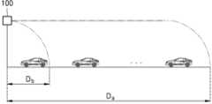
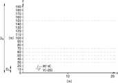
도 2는 본 발명의 바람직한 일 실시예로서, 차량 감지부가 차량을 감지할 수 있는 구간 및 촬영부가 차량을 촬영할 수 있는 구간을 나타낸다.
도 3a 내지 도 3b는 일 실시예에 따른 속도 감지 데이터이다.
도 4a 내지 도 4d는 일 실시예에 따른 속도 감지 데이터이다.
도 5a 내지 도 5c는 일 실시예에 따른 속도 감지 데이터이다.
도 6은 본 발명의 바람직한 일 실시예로서, 차량의 속도 위반 검출 방법의 순서도를 나타낸 것이다.1 is a configuration diagram of a speeding vehicle detection system as a preferred embodiment of the present invention.
Figure 2 shows a section in which the vehicle detecting unit can detect the vehicle and a section in which the photographing unit can photograph the vehicle as a preferred embodiment of the present invention.
3A to 3B are speed sensing data according to an exemplary embodiment.
4A to 4D are speed sensing data according to an exemplary embodiment.
5A to 5C are speed sensing data according to an exemplary embodiment.
6 is a flowchart illustrating a method for detecting a speeding violation of a vehicle as a preferred embodiment of the present invention.
이하, 첨부된 도면을 참조하여 실시예를 상세히 설명하기로 한다. 설명되는 실시예는 단지 예시적인 것에 불과하며, 이러한 실시예들로부터 다양한 변형이 가능하다. 이하의 도면들에서 동일한 참조부호는 동일한 구성요소를 지칭하며, 도면 상에서 각 구성요소의 크기는 설명의 명료성과 편의상 과장되어 있을 수 있다.Hereinafter, embodiments will be described in detail with reference to the accompanying drawings. The described embodiments are merely illustrative, and various modifications are possible from these embodiments. In the following drawings, the same reference numerals denote the same components, and the size of each component in the drawings may be exaggerated for clarity and convenience of description.
또한, 명세서에 기재된 “...부” 등의 용어는 적어도 하나의 기능이나 동작을 처리하는 단위를 의미하며, 이는 하드웨어 또는 소프트웨어로 구현되거나 하드웨어와 소프트웨어의 결합으로 구현될 수 있다.In addition, terms such as "... unit" described in the specification mean a unit that processes at least one function or operation, which may be implemented as hardware or software, or a combination of hardware and software.
이하에서, "상부" 나 "상"이라고 기재된 것은 접촉하여 바로 위에 있는 것뿐만 아니라 비접촉으로 위에 있는 것도 포함할 수 있다. 마찬가지로, “하부” 나 “아래”라고 기재된 것은 접촉하여 바로 밑에 있는 것뿐 만 아니라 비접촉으로 아래에 있는 것도 포함할 수 있다.Hereinafter, what is described as "above" or "above" may include not only what is directly on top of contact but also what is on top of non-contact. Similarly, references to “below” or “below” may include directly under contact as well as under non-contact.
단수의 표현은 문맥상 명백하게 다르게 뜻하지 않는 한, 복수 개의 표현을 포함한다. 또한 어떤 부분이 어떤 구성요소를 "포함"한다고 할 때, 이는 특별히 반대되는 기재가 없는 한 다른 구성요소를 제외하는 것이 아니라 다른 구성요소를 더 포함할 수 있는 것을 의미한다.Expressions in the singular number include plural expressions unless the context clearly dictates otherwise. In addition, when a certain component is said to "include", this means that it may further include other components without excluding other components unless otherwise stated.
“상기”의 용어 및 이와 유사한 지시 용어의 사용은 단수 및 복수 모두에 해당하는 것일 수 있다.The use of the term “above” and similar denoting terms may correspond to both singular and plural.
“연결”의 의미는 물리적 연결은 물론, 광학적 연결, 전기적 연결 등을 포함할 수 있다.The meaning of “connection” may include not only a physical connection, but also an optical connection, an electrical connection, and the like.
또한, 모든 예시적인 용어(예를 들어, 등등)의 사용은 단순히 기술적 사상을 상세히 설명하기 위한 것으로서 청구항에 의해 한정되지 않는 이상 이러한 용어로 인해 권리 범위가 한정되는 것은 아니다.In addition, the use of all exemplary terms (for example, etc.) is simply for explaining technical ideas in detail, and the scope of rights is not limited due to these terms unless limited by claims.
제1, 제2 등의 용어는 다양한 구성 요소들을 설명하는데 사용될 수 있지만, 구성 요소들은 용어들에 의하여 한정되어서는 안된다. 용어들은 하나의 구성 요소를 다른 구성 요소로부터 구별하는 목적으로만 사용된다.Terms such as first and second may be used to describe various components, but the components should not be limited by the terms. Terms are used only to distinguish one component from another.
도 1은 본 발명의 바람직한 일 실시예로서, 속도 위반 차량 검출 시스템의 구성도이고, 도 2는 차량 감지부가 차량을 감지할 수 있는 구간 및 촬영부가 차량을 촬영할 수 있는 구간을 나타낸 단면도이다.1 is a configuration diagram of a speeding vehicle detection system as a preferred embodiment of the present invention, and FIG. 2 is a cross-sectional view showing a section in which a vehicle detecting unit can detect a vehicle and a section in which a photographing unit can photograph a vehicle.
도 1을 참조하면, 예시적인 실시예에 따른 속도 위반 차량 검출 시스템(100)은 적어도 하나의 레이더(121)를 포함하며, 레이더(121)를 이용하여 차량 감지부로부터 차량까지의 거리와 차량의 속도를 감지하는 차량 감지부, 차량의 속도가 제한 속도 위반임을 결정하고, 제한 속도 위반 시 차량을 촬영하도록 제어하는 제어부(130), 제어부(130)로부터 작동 신호를 인가받아 차량의 일부분 또는 전체를 촬영하는 촬영부(111), 및 촬영부(111)로부터 촬영된 차량의 사진 또는 영상을 외부 서버로 송신하고 외부 서버로부터 데이터를 수신할 수 있는 통신부(140)를 포함할 수 있다.Referring to FIG. 1 , a speeding
예시적인 실시예에서, 차량감지부(120)는 레이더(121)에서 획득한 차량이 검출된 시간, 차량의 속도, 시간구간별 차량의 속도 변화량, 차량의 속도위반 여부, 차량감지부(120)부터 차량까지의 거리, 차량감지부(120)의 레이더(121)에서 차량을 검출한 지점부터 차량감지부(120)까지의 구간 동안 차량이 속도를 위반한 횟수 또는 인터벌, 속도를 위반한 구간 정보 등을 포함하는 차량데이터를 파악할 수 있다. 그리고, 이상의 데이터를 학습데이터로 기학습한 인공신경망(미 도시)를 더 포함하여, 레이더(121)에서 획득한 상기 차량데이터를 기준으로 해당 차량을 영상촬영장치를 이용하여 촬영할지 여부를 판단할 수 있다.In an exemplary embodiment, the
또한, 예시적인 실시예에 따른 속도 위반 차량 검출 시스템(100)의 차량 감지부, 제어부(130) 및 통신부(140)는 하나의 레이더 칩(100) 의 형태로 구현될 수 있으며, 레이더 칩(100)은 촬영부(111)에 내장되거나, 외부에 장착되거나, 또는 전기적으로 연결되어 동작할 수 있다. 예시적인 실시예에 따른 속도 위반 차량 검출 시스템(100)은 차량과의 거리 및 차량 속도 감지를 레이더(121)로 하고, 속도 위반 차량 검출 시 또는 차량 접근 시 등 특정 경우에만 카메라를 작동시킴으로써 카메라 작동으로 인한 전력 소모를 줄일 수 있고, 저장되는 영상 용량을 줄일 수 있다. 본 발명의 또 다른 바람직한 일 실시예에서, 레이더(121)는 먼 거리 범위의 복수의 차량의 속도를 검출할 수 있고, 단일 레이더 칩(100) 형태로 구현되어 촬영부(111)와 통합되므로 시스템 설치 및 유지 비용이 기존의 속도 검출 시스템보다 낮아질 수 있다.In addition, the vehicle detection unit, the
예시적인 실시예에 따른 속도 위반 차량 검출 시스템(100)은 차량 감지부(120)를 포함할 수 있다. 차량 감지부(120)는 적어도 하나 이상의 레이더(121)를 포함하며, 레이더(121)는 전자파를 방출하여 차량의 속도를 감지할 수 있다. 레이더(121)는 적어도 하나 이상의 광원 및 적어도 하나 이상의 검출기를 포함할 수 있다. 레이더(121)는 레이더(121)로부터 발산된 전파가 물체에 반사되어 돌아오는 시간을 이용하여 물체와의 거리를 측정할 수 있고, 물체의 속도에 따라 반사되어 돌아오는 전파의 주파수가 바뀌는 도플러 효과를 통해 차량의 속도를 감지할 수 있다. 레이더(121)는 하나의 차량의 속도를 감지할 수도 있으며, 복수의 차량의 속도를 동시에 감지할 수 있다. 또한 적어도 하나의 차량을 멀티트래킹할 수 있다. 차량 감지부(120)는 차량 감지부(120)가 설치된 지점을 기준으로 0m 내지 1000m까지 범위의 차량의 속도를 감지할 수 있다. 또는, 0m 내지 300m까지 범위의 차량의 속도를 감지할 수 있다. 본 발명의 바람직한 일 실시예에서, 상기 범위의 구간을 차량 감지부(120)에서 차량을 감지할 수 있는 구간(Da)이라 한다. 차량 감지부의 레이더(121)는 일반적인 카메라보다 전력 소모가 적을 수 있다. 도 2에 따르면, 차량 감지부는 차량을 감지할 수 있는 구간(Da) 내에서 차량을 감지할 수 있으며, 이 구간동안 차량 감지부와 차량의 거리, 차량의 속도, 속도위반회수 중 적어도 하나를 제어부(130)에 송신할 수 있다. 여기서, 속도위반회수는 차량 감지부의 측정 주기의 한 시구간을 일 프레임이라고 할 때, 속도 위반으로 감지된 프레임이 N개라면, N번의 속도위반회수가 감지되었다고 할 수 있다.The speeding
레이더(121)는 특정 크기 이상의 물체의 속도를 감지할 수 있다. 예를 들어, 레이더(121)는 소형차 크기 이상의 물체의 속도를 감지할 수 있다. 이에 따라, 속도 감지 물체에 대한 노이즈를 줄일 수 있다.The
예시적인 실시예에 따른 속도 위반 차량 검출 시스템(100)은 촬영부(111)를 포함할 수 있다. 촬영부(111)는 적어도 하나의 카메라를 포함할 수 있다. 카메라는 작동 신호를 받으면 작동되어(ON상태가 되어) 차량을 촬영할 수 있다. 작동 신호는 제어부(130)로부터 인가받을 수 있으며, 카메라는 작동 신호를 인가 받은 다음, 일정 시간 후 작동이 중지될 수도 있으며(오프상태 또는 대기상태가 될 수 있으며), 제어부(130)의 신호에 따라 작동이 중지될 수도 있다. 카메라는 차량이 나타나는 사진을 촬영할 수도 있으며, 차량이 나타나는 동영상을 촬영할 수도 있다. 카메라는 차량의 전체 부분을 촬영할 수도 있으며, 차량의 일 부분만을 촬영할 수도 있다. 예를 들어, 차량의 일 부분은 차량의 번호판일 수 있다. 촬영된 사진 또는 영상은 통신부(140)를 통해 관리 서버(200) 등 외부로 전송될 수 있다. 또는, 촬영된 사진 또는 영상은 제어부(130)를 거쳐 일련의 처리를 거친 후 관리 서버(200) 등 외부로 전송될 수도 있다.The speeding
적어도 하나의 카메라는 제1 카메라 및 제2 카메라를 포함할 수 있다. 예를 들어, 제1 카메라와 제2 카메라는 10m 이상 이격되어 배치될 수 있다. 제1 카메라와 제2 카메라는 동일한 일 레이더(121)와 연결될 수 있다. 예를 들어, 레이더(121)가 200m 전방에서 차량 속도 위반을 감지한다면, 레이더(121) 전방으로 150m 떨어진 제1 카메라가 작동될 수 있고, 레이더(121) 전방으로 100m 떨어진 제2 카메라가 작동될 수 있다. 일 레이더(121)와 복수의 카메라가 대응되어 효율적으로 속도 위반 여부를 판별 및 촬영할 수 있다.The at least one camera may include a first camera and a second camera. For example, the first camera and the second camera may be disposed apart from each other by 10 m or more. The first camera and the second camera may be connected to the
적어도 하나의 카메라를 포함하는 촬영부(111)는 제어부(130)로부터 작동 신호가 인가되지 않을 때는 대기 모드 또는 오프 모드가 될 수 있다. 작동 신호가 인가되는 정상 작동 모드에서는 촬영 및 저장이 수행될 수 있다. 반면, 대기 모드는 저전력 상태로, 전원이 켜져는 있지만, 촬영을 하지 않거나, 또는 촬영은 하지만 저장을 하지 않는 상태일 수 있다. 오프 모드는 촬영부(111)의 전원이 꺼진 상태일 수 있다.The photographing
도 2에 따르면, 촬영부(111)가 차량을 촬영할 수 있는 구간(Db)은 차량 감지부가 차량을 감지할 수 있는 구간(Da)보다 작을 수 있다. 촬영부(111)가 차량을 촬영할 수 있는 구간(Db)는 촬영부(111)의 장치마다 상이할 수 있으며, 차량번호를 식별할 수 있는 구간을 지칭할 수 있으며, 기설정된 값으로 지정될 수 있다. 예를 들면, 촬영부(111)가 차량을 촬영할 수 있는 구간(Db)은 0m 내지 20m일 수 있다.According to FIG. 2 , the interval Db in which the photographing
예시적인 실시예에 따른 속도 위반 차량 검출 시스템(100)은 제어부(130)를 포함할 수 있다. 제어부(130)는 차량의 속도가 제한 속도 위반임을 결정할 수 있는 과속 판별부(131)를 포함할 수 있다. 제어부(130)는 차량 감지부(120)로부터 감지된 차량과의 거리 및 차량의 속도를 송신받을 수 있다. 과속 판별부(131)는 송신된 차량의 속도를 도로에서 설정된 제한 속도 값과 비교하여 차량의 속도가 제한 속도 위반임을 결정할 수 있다. 차량의 속도가 제한 속도보다 아래라면, 제한 속도 위반이 아님을 결정할 수 있고, 촬영부(111)로 작동 신호를 인가하지 않을 수 있다. 차량의 속도가 제한 속도보다 위라면, 차량이 제한 속도를 위반 했음을 결정할 수 있고, 촬영부(111)로 작동 신호를 인가할 수 있으며, 촬영부(111)가 작동 될 수(ON 상태가 될 수) 있다. 촬영부(111)가 ON 상태가 된 후 일정 시간이 지난다면, 촬영부(111) 자체가 OFF 상태가 되거나, 또는 제어부(130)가 촬영부(111)에 작동 중지 신호를 인가하여 촬영부(111)를 OFF 상태로 바꿀 수 있다.The speeding
예를 들어, 차량이 차량 감지부가 감지하는 구역 내에서 일 순간(t1) 제한 속도를 초과하면, 그 일 순간(t1) 후에 제한 속도를 초과하지 않더라도 과속 판별부(131)에 의해 차량이 제한 속도 위반이라고 결정될 수 있다. 이 경우, 촬영부(111)가 촬영할 수 있는 구역 내에서 차량이 제한 속도보다 낮은 속도를 가지더라도, 촬영부(111)가 차량을 촬영하도록 제어부(130)가 작동 신호를 인가할 수 있다.For example, if the vehicle exceeds the speed limit at one instant (t1 ) within the zone detected by the vehicle detector, the vehicle is detected by the speeding
또는, 차량 감지부(120)가 감지하는 구역 내에서 제한 속도보다는 낮지만, 특정 속도 이상으로 주행하는 차량을 인식 시에 차량 감지부(120)는 제어부(130)를 통해 촬영부(111)에 작동 신호를 인가하여, 차량을 촬영할 수도 있다. 상기 특정 속도 이상으로 주행하는 경우 그 이하 속도로 행하는 경우보다 제한 속도를 위반할 확률이 높으므로, 속도 위반 차량 검출 시스템(100)은 특정 속도 이상의 차량을 선택적으로 촬영할 수 있다. 위와 마찬가지로, 차량 감지부가 감지하는 구역 내에서 일 순간 특정 속도를 초과하면, 그 일 순간 후에 제한 속도를 초과하지 않더라도 제어부(130)에 의해 촬영부(111)로 작동 신호가 인가될 수 있다. 예를 들어, 차량 감지부가 차량을 감지할 수 있는 구간(Da) 내에서 차량이 일정 속도 이상 10 프레임 이상(예를 들어, 1 프레임이 0.1초라 한다면, 1초 이상 일정 속도 이상이라면) 감지된다면, 촬영부(111)가 차량을 촬영할 수 있는 구간(Db) 내에서 차량의 속도가 제한 속도보다 높지 않더라도, 해당 차량을 촬영할 수 있고, 촬영된 차량 정보는 Da 구간 동안의 속도 변화량과 함께 이를 매칭될 수 있다.Alternatively, when recognizing a vehicle traveling at a specific speed or higher but lower than the speed limit within the area detected by the
다른 예를 들면, 차량 감지부가 차량을 감지할 수 있는 구간(Da) 내에서 일정 거리 안에 진입하면, 제어부(130)가 촬영부(111)에 작동 신호를 인가하여, 차량을 촬영할 수도 있다. 상기 일정 거리는 촬영부(111)가 차량을 촬영할 수 있는 구간(Db)의 일 단일 수 있고, 그 일단보다 10m 이전의 거리일 수도 있다. 이는, 차량의 속도와 관계없이 차량의 일정 거리 구역 진입에 따라 차량을 촬영하는 것으로, 차량 통행이 적은 지역에 바람직할 수 있다. 하지만, 차량 통행이 적은 지역에 한정되지 않고 다양한 지역에서 사용될 수도 있다.For another example, when the vehicle detecting unit enters within a predetermined distance within the rangeD a capable of detecting the vehicle, the
예시적인 실시예에 따른 속도 위반 차량 검출 시스템(100)의 제어부(130)는 차량 번호 추출부(132)를 더 포함할 수 있다. 촬영부(111)에서 촬영된 속도 위반 차량의 사진 또는 영상은 제어부(130)로 송신될 수 있다. 차량 번호 추출부(132)는 촬영된 사진 또는 영상에서 차량의 차량 번호를 인식하여 추출할 수 있다. 추출된 차량 번호는 통신부(140)를 통해 관리 서버(200) 등으로 전송될 수 있다.The
예시적인 실시예에 따른 속도 위반 차량 검출 시스템(100)의 제어부(130)는 벌금 결정부(133)를 더 포함할 수 있다. 벌금 결정부(133)는 일 차량이 과속 차량을 결정될 시에 외부 서버로부터 상기 차량의 과속 기록을 수신할 수 있다. 이 때, 외부 서버는 차량 등록 서버(300)일 수 있으며, 차량 등록 서버(300)에 과속 차량에 대한 정보를 요청하고, 그에 대한 피드백으로 차량의 과속 기록을 수신받을 수 있다. 수신받은 차량의 과속 기록에 따라 벌금 결정부(133)는 차량의 과속 벌금을 계산할 수 있고, 계산된 벌금과 벌금을 받은 차량에 대한 정보는 통신부(140)를 통해 차량 등록 서버(300), 또는 다른 외부 서버로 송신될 수 있다. 이 때, 다른 외부 서버는 속도 위반 차량 검출 시스템(100)에서 얻어진 자료 등을 관리하는 관리 서버(200)일 수 있다.The
예시적인 실시예에 따른 속도 위반 차량 검출 시스템(100)의 제어부(130)는 차량 감지부에서 감지되는 차량과의 거리 및 차량의 속도에 대한 데이터를 저장할 수 있다. 데이터는 차량 감지부가 감지하는 구역에서 검출된 차량 감지부와 차량과의 거리 및 차량의 속도를 나열한 표 등의 데이터 시트일 수도 있고, 속도를 위반한 순간 거리 및 속도를 데이터를 그래프 형태로 나타낸 데이터일 수도 있고, 감지 구역 전체에서 거리 및 속도를 그래프로 보여주는 일련의 데이터일 수도 있다. 일련의 데이터는 동영상 형태로 저장될 수 있다. 제어부(130)는 차량 감지부에서 감지되는 차량 감지부와 차량과의 거리 및 차량의 속도에 대한 데이터를 차량의 사진 또는 영상과 함께 상기 외부 서버로 송신할 수 있다.The
제어부(130)는 차량 감지부와 별도의 부로 나뉘어 설명되었지만, 이에 한정되지 않고 제어부(130)와 차량 감지부는 단일 칩으로 구성되어 속도 감지와 함께 과속 여부를 판단할 수도 있고, 촬영부(111)의 작동을 제어할 수도 있다.Although the
제어부(130)는 프로세서의 형태로 구현될 수 있다. 또 다른 일 실시예에서 제어부(130)는 하드웨어적으로는 통상적인 웹서버(Web Server) 또는 네트워크(500) 서버와 동일한 구성을 가질 수 있다. 그러나 소프트웨어적으로는 C, C++, Java, Visual Basic, Visual C 등 여하한 언어를 통하여 구현되는 프로그램 모듈을 포함할 수 있다. 제어부(130)는 웹서버 또는 네트워크(500) 서버의 형태로 구현될 수 있으며, 웹서버는 일반적으로 인터넷과 같은 개방형 컴퓨터 네트워크(500)를 통하여 불특정 다수 클라이언트 또는 다른 서버와 연결되어 있고, 클라이언트 또는 다른 웹서버의 작업수행 요청을 접수하고 그에 대한 작업 결과를 도출하여 제공하는 컴퓨터 시스템 및 그를 위하여 설치되어 있는 컴퓨터 소프트웨어(웹서버 프로그램을)을 뜻할 수 있다. 그러나, 전술한 웹서버 프로그램 이외에도, 상기 웹서버상에서 동작하는 일련의 응용 프로그램(Application) 또는 경우에 따라서는 내부에 구축되어 있는 각종 데이터베이스를 포함하는 넓은 개념으로 이해될 수도 있다. 제어부(130)와 연결되는 "?? 부" 또는 주차장 플랫폼에 속하는 "??부"일반적인 서버용 하드웨어 도스(DOS), 윈도우(Windows), 리눅스(Linux), 유닉스(Unix), 매킨토시(Macintoish)등의 운영체제에 따라 다양하게 제공되고 있는 웹서버 프로그램을 이용하여 구현될 수 있으며, 대표적으로는 윈도우 환경에서 사용되는 웹사이트(Website), IIS(Internet Information Server)와 유닉스 환경에서 사용되는 CERN, NCSA, APPACH 등이 이용될 수 있다.The
예시적인 실시예에 따른 속도 위반 차량 검출 시스템(100)은 통신부(140)를 포함할 수 있다. 통신부(140)는 속도 위반 차량 검출 시스템(100)의 데이터 등을 네트워크(500)를 통해 다른 서버 또는 시스템 등과 송수신할 수 있다. 촬영부(111)로부터 촬영된 사진 또는 영상은 통신부(140)를 통해 관리 서버(200)로 전송될 수 있다. 또는 차량 번호 추출부(132)에서 추출된 차량 번호는 통신부(140)를 통해 관리 서버(200)로 전송될 수 있다. 통신부(140)는 상기 예처럼 별도의 구성일 수도 있으나, 이에 한정되지 않고 제어부(130) 또는 각 ?? 부에 포함될 수도 있다.The speeding
차량 감지부, 제어부(130), 및 통신부(140)는 일 레이더 칩(100)(single radar chip)으로 구성될 수 있다. 적어도 하나의 카메라를 포함하는 촬영부(111)에 일 레이더 칩(100)이 내장되거나, 장착되거나, 또는 전기적으로 연결되어 통합될 수 있다. 레이더 칩(100)이 카메라를 포함하는 촬영부(111)에 내장되거나 장착된다면, 카메라와 차량 감지부가 접할 수 있다. 레이더 칩(100)이 카메라를 포함하는 촬영부(111)와 유선 또는 무선을 통해 전기적으로 연결되어 통합된다면, 촬영부(111)와 차량 감지부는 접할 수도 있고, 이격되어 배치될 수도 있다. 카메라와 일 레이더 칩(100)은 소프트웨어 등을 통해 통합될 수 있으며, 속도 위반 차량 검출 시스템(100)을 구현할 수 있다. 예를 들어, 레이더 칩(100)이 일 차량의 속도 위반이라는 출력을 얻으면, 상기 소프트웨어 등을 통해 상기 출력이 카메라에 작동 입력이 될 수 있고, 카메라는 과속 차량에 대한 정보를 담은 사진 또는 영상의 출력을 생성할 수 있다. 위와 같이 차량 감지부, 제어부(130), 및 통신부(140)를 일 레이더 칩(100)으로 구성하여 촬영부(111)에 내장되거나, 장착되거나, 또는 전기적으로 연결되어 통합된다면, 레이더 장치와 카메라 장치를 별도로 사용하는 경우보다 통신 이상 등의 문제에 대하여 자유로울 수 있으며, 서로 간의 반응 속도가 충분히 빨라 빠른 속도의 차량을 인식 및 검출할 수 있다.The vehicle detection unit, the
예시적인 실시예에 따른 속도 위반 차량 검출 시스템(100)은 저장부(150)를 더 포함할 수 있다. 저장부(150)는 데이터베이스의 형태일 수 있다. 저장부(150)는 속도 위반 차량 검출 시스템(100)이 설치된 도로의 제한 속도, 제한 속도 위반시 과태료 또는 벌금, 과속 차량 데이터 등의 정보가 저장될 수 있다. 상기 제한 속도는 시간 별 제한 속도 등 여러가지 조건 하의 제한 속도의 정보일 수 있다. 도로의 제한 속도는 제어부(130)에 전송되어 과속 판별 시 사용될 수 있다.The speeding
예시적인 실시예에 따른 속도 위반 차량 검출 시스템(100)은 네트워크(500)를 통해 관리 서버(200) 또는 차량 등록 서버(300) 등과 연결될 수 있다. 네트워크(500)는 인터넷망, 인트라넷망, 이동통신망, 위성통신망 등 다양한 유무선 통신 기술을 이용하여 인터넷 프로토콜로 데이터를 송수신할 수 있는 망을 의미할 수 있다. 또한, 네트워크(500)는 통신부와 결합되어 하드웨어, 소프트웨어 등의 컴퓨터 자원을 저장하고, 클라이언트가 필요로 하는 컴퓨팅 자원을 외부 기기로 제공할 수 있는 클라우딩 컴퓨팅망을 포함할 수 있다.The speeding
여기서, 클라우드 컴퓨팅이란 정보가 인터넷 상의 서버에 영구적으로 저장되고, 데스크톱, 테블릿 컴퓨터, 노트북, 넷북, 스마트폰 등의 클라이언트 단말기에 일시적으로 보관되는 컴퓨터 환경을 의미할 수 있으며, 클라우드 컴퓨팅은 사용자의 모든 정보를 인터넷 상의 서버에 저장하고, 이 정보를 각종 IT 기기를 통하여 언제 어디서든 이용할 수 있도록 하는 컴퓨터 환경 접속망을 의미할 수 있다.Here, cloud computing may refer to a computer environment in which information is permanently stored in a server on the Internet and temporarily stored in client terminals such as desktops, tablet computers, laptops, netbooks, and smart phones. It may refer to a computer environment access network that stores all information in a server on the Internet and makes this information available anytime and anywhere through various IT devices.
이러한, 네트워크(500)의 개념에 대해 추가적으로 부연 설명하자면, 네트워크(500)는 LAN(Local Area Network), WAN(Wide Area Network)등의 폐쇄형 네트워크, 인터넷(Internet)과 같은 개방형 네크워크 뿐만 아니라, CDMA(Code Division Multiple Access), WCDMA(Wideband Code Division Multiple Access), GSM(Global System for Mobile Communications), LTE(Long Term Evolution), EPC(Evolved Packet Core) 등의 네트워크와 향후 구현될 차세대 네트워크 및 클라우드 컴퓨팅 네트워크를 통칭하는 개념일 수 있다.To further explain the concept of the
예시적인 실시예에 따른 속도 위반 차량 검출 시스템(100)은 차량 등록 서버(300)로부터 차량의 정보를 받을 수 있으며, 관리 서버(200)에 데이터를 전송하여 데이터 저장 및 관리 등을 할 수 있다.The speeding
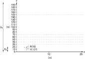
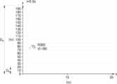
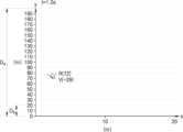
도 3a 내지 도 3b는 일 실시예에 따른 속도 감지 데이터이고, 도 4a 내지 도 4d는 일 실시예에 따른 속도 감지 데이터이고, 도 5a 내지 도 5c는 일 실시예에 따른 속도 감지 데이터이다.3A to 3B are speed sensing data according to an exemplary embodiment, FIGS. 4A to 4D are speed sensing data according to an exemplary embodiment, and FIGS. 5A to 5C are speed sensing data according to an exemplary embodiment.
상기 도 3a 내지 도 5c를 참고하여, 속도 위반 차량 검출 시스템(100)의 작동예를 설명한다.An operation example of the speeding
도 3a 내지 도 5c를 참조하면, 차량 감지부 및 제어부(130)는 차량과 차량 감지부 사이의 거리(R), 차량의 속도(V), 차량의 속도위반여부, 시간 등의 정보를 제공할 수 있다. 차량 감지부는 차량 감지부 사이의 거리, 차량의 속도, 시간을 측정하여 연관데이터 형태로 제어부(130)에 제공할 수 있다. 상기 연관데이터는 레이더(121)의 측정 주기마다의 거리(R), 시간, 속도(V) 정보를 포함하는 데이터 시트 형태일 수도 있다. 본 발명의 또 다른 바람직한 일 실시예에서는 상기 차량감지부에서 제공하는 연관데이터와 촬영부에서 촬영한 영상데이터를 매핑하여 관리자 단말기의 표시부에 표시할 수 있다.3A to 5C , the vehicle detecting unit and
본 발명의 바람직한 일 실시예로서, 차량감지부는 Db-Da 구간에서 차량의 속도위반이 검출된 경우, Da 구간에서 속도위반여부와 관계없이 차량을 촬영할 수 있다. 표시부는 Da 구간에서 속도위반이 검출되지 않은 차량 중 Db-Da 구간에서 차량의 속도위반이 검출된 차량에 대해 관리자 단말기에 정보를 제공할 수 있다. 본 발명의 바람직한 일 실시예에서 차량감지부는 Da 구간에서 속도위반이 검출되지 않았으나, Db-Da 구간에서 차량의 속도위반이 검출된 차량에 대한 정보를 누적하여 저장하고, 누적회수가 기설정된 회수 이상인 경우 상기 정보를 통해 재구성된 일련의 사진 또는 동영상 데이터를 관리자 단말기에 제공하여 추후 벌금의 근거로 이용할 수 있다. 일련의 사진 또는 동영상 데이터는 도로와 수직한 거리인 x축 및 도로와 평행한 거리인 y축을 가진 그래프 상에 표현된 차량을 나타낼 수 있다. 그래프 상의 원은 차량을 나타낼 수 있고, 원의 위치는 차량의 위치에 대응될 수 있다. 그래프 상의 점들은 차량에 반사된 광이 레이더(121)의 검출기로 들어온 인풋들일 수 있다. 그래프 상의 원은 그래프 상의 점의 평균 값을 나타낸 것일 수 있다. 또는, 그래프 상의 원은 그래프 상의 점들 중 일정 범위 안의 점들의 평균값일 수 있다. 상기 일정 범위 안의 점들은 점들의 분포 상 밀집 분산이 낮은 점들일 수도 있고, 그 전 레이더(121) 측정을 통해 얻어진 차량의 위치(그 전 측정을 통해 얻어진 그래프 상의 원)를 바탕으로 차량의 다음 위치로 예상되는 일정 범위 내의 점들일 수도 있다. 다만, 이에 한정되지 않고, 그래프 상의 점들은 다양한 알고리즘을 통해 차량의 위치로 계산될 수 있다. 원의 우측 상단에 표시되는 숫자 중 하나는 차량과 차량 감지부 사이의 거리(R)를 나타낼 수 있다. 원의 우측 상단에 표시되는 숫자 중 하나는 차량의 속도(V)를 나타낼 수 있다. 차량과 차량 감지부 사이의 거리(R)와 차량의 속도(V)는 레이더(121)의 측정 주기마다 갱신되어 표시될 수 있다. 제어부(130)가 차량의 속도위반여부를 결정할 수 있고, 그래프 상의 원 중 제한 속도를 넘는 원과 제한 속도를 넘지 않은 원은 서로 다른 색의 원으로 표시될 수 있다. 예를 들어, 제한 속도를 넘는 원은 빨간색으로, 제한 속도를 넘지 않은 원은 파란색으로 표시될 수 있다. 다만, 상기 차량의 속도위반여부를 나누기 위한 표시 방법은 색상에 제한되지 않고, 다른 형상의 도형으로 표시될 수도 있다. 예를 들어, 제한 속도를 넘는 차량은 원 내부에 십자가 모양을 포함한 원으로 표시되고, 제한 속도를 넘지 않는 차량은 원 내부에 십자가 모양이 없는 원으로 표시될 수 있다. 또한, 상기 색상을 나누는 표시는 속도위반여부를 기준으로 하는 것에 제한되지 않고, 일정 속도를 기준으로 나뉘어질 수 있다. 이 때, 일정 속도는 제한 속도보다 낮은 속도일 수 있다. 상기 데이터들은 레이더(121)의 측정 주기마다 저장된 데이터를 통해 재구성된 것일 수 있다. 데이터의 한 프레임마다 대응되는 시각이 저장될 수 있고, 이에 따라 차량 감지부는 시간의 정보 등을 제공할 수 있다.As a preferred embodiment of the present invention, the vehicle detection unit, when a speed violation of the vehicle is detected in the section Db-Da, may photograph the vehicle in the section Da regardless of whether or not the speed violation occurs. The display unit may provide information to the manager terminal about vehicles for which a speed violation is detected in a section Db-Da among vehicles for which a speed violation is not detected in a section Da. In a preferred embodiment of the present invention, the vehicle detection unit accumulates and stores information on vehicles in which speed violations are detected in the Db-Da section, even though no speed violation is detected in the section Da, and the cumulative number of times is greater than or equal to a preset number of times. In this case, a series of photo or video data reconstructed through the above information can be provided to the administrator's terminal and used as a basis for future fines. A series of photo or video data may represent a vehicle represented on a graph with an x-axis being a distance perpendicular to the road and a y-axis being a distance parallel to the road. A circle on the graph may represent a vehicle, and a location of the circle may correspond to a location of the vehicle. Points on the graph may be inputs of light reflected from the vehicle to the detector of the
도 3a 내지 도 3b를 참고하면, 차량 감지부가 차량을 감지할 수 있는 구역 내에서 차량이 일 순간 제한 속도(예를 들어, 30km/h)를 초과하면, 제어부(130)는 그 후 차량의 속도와 상관없이 차량을 촬영하도록 촬영부(111)에 작동 신호를 인가할 수 있다. 예를 들면, 차량 감지부가 차량을 감지할 수 있는 구간(Da)은 0m 내지 200m일 수 있다. 도 3a에 따르면, 차량이 차량 감지부로부터 150m 떨어진 지점에서 제한 속도를 초과하는 경우에 제어부(130)는 상기 차량을 촬영하도록 촬영부(111)에 작동 신호를 인가할 수 있다. 예를 들면, 도 3a의 데이터 상에 150m 떨어진 차량은 32km/h의 속도를 가지며, 30km/h를 초과하는 속도의 차량은 내부에 십자가를 포함하는 원으로 표시될 수 있다. 촬영부(111)가 차량을 촬영할 수 있는 구간(Db)이 0m 내지 20m 라면, 상기 150m에서 과속한 차량이 0m 내지 20m를 지나는 동안 제한 속도를 넘지 않더라도 촬영부(111)에 의해 촬영될 수 있다. 따라서, 도 3b와 같이 0m 내지 20m를 지나는 차량이 제한 속도인 30km/h 낮은 속도를 가지고 있다고 하더라도, 촬영부(111)에 의해 촬영될 수 있다. 예를 들면, 도 3b의 데이터 상에 16m 떨어진 차량은 27km/h의 속도를 가지며, 30km/h를 초과하지 않는 속도의 차량은 내부에 십자가를 포함하지 않는 원으로 표시될 수 있다. 촬영된 사진 또는 영상은 차량 감지부에서 제공되는 정보와 함께 제공될 수 있다. 다시 말하면, 제한 속도를 넘는 일 순간 데이터 또는, 그 앞뒤의 시간을 포함하는 일련의 데이터 세트가 촬영된 사진 또는 영상과 함께 저장부(150)에 저장되거나 또는 관리 서버(200)로 송신될 수 있다. 이 때, 상기 일 순간 또는 일련의 데이터 세트를 통해 차량이 과속했음을 확인할 수 있으며, 사진 또는 영상을 통해 차량의 정보를 확인할 수 있다. 만약, 차량이 그 전에는 제한 속도를 넘지 않다가, 촬영부(111)가 차량을 촬영할 수 있는 구간(Db)을 진입한 후 제한 속도를 넘기 시작한다면, 이것도 또한 차량 감지부에 의해 감지될 수 있으므로, 제어부(130)는 지체없이 촬영부(111)를 작동시켜 차량을 촬영할 수 있다.Referring to FIGS. 3A and 3B , if the vehicle exceeds the speed limit (eg, 30 km/h) for one moment within a region where the vehicle detection unit can detect the vehicle, the
도 4a 내지 도 4d를 참고하면, 차량 감지부가 특정 속도 이상의 차량을 일정 횟수 또는 일정 시간 이상 감지될 시, 제어부(130)가 촬영부(111)에 작동 신호를 인가할 수 있다. 여기서, 특정 속도는 제한 속도보다 낮은 속도일 수 있다. 예를 들어, 제한 속도를 30km/h이고, 특정 속도를 28km/h라고 할 수 있다. 이 경우, 특정 속도 이상의 차량은 데이터 상에 마름모로 표시될 수 있고, 특정 속도 미만의 차량은 데이터 상에 원으로 표시될 수 있다. 레이더(121)의 측정 주기마다 차량의 속도가 특정 속도 이상인지 여부, 즉, 마름모로 표시되는지 여부가 결정될 수 있다. 예를 들어, 차량이 차량 감지부 차량을 감지할 수 있는 구간(Da) 내에서 총 1초 이상 마름모로 인식 및 검출될 시, 제어부(130)는 촬영부(111)에 작동 신호를 인가하도록 구성될 수 있다. 레이더(121)의 측정 주기마다 차량의 거리 및 속도가 갱신되므로, 레이더(121)의 일 측정을 일 프레임이라고 할 수 있다. 예를 들어, 레이더(121)의 측정 주기는 0.1초, 즉 일 프레임은 0.1초마다 갱신되면, 일련의 데이터 상에 차량이 10 프레임 이상 빨간색 원으로 인식되면, 제어부(130)는 촬영부(111)에 작동 신호를 인가하도록 구성될 수 있다. 상기 프레임 수는 속도 위반 회수에 대응될 수 있다. 특정 속도 이상의 차량은 속도 측정 구간(Da) 내에서 제한 속도를 초과할 가능성이 높으므로, 이와 같은 방식의 예로 속도 위반 차량 검출 시스템(100)이 작동될 수 있다. 도 4a에 따르면, t=0s 일 때, 차량이 28km/h로 마름모로 나타나며, 도 4b에 따르면, t=0.5s 일때, 차량이 29km/h로 마름모로 나타나며, 도 4c에 따르면 t=1.0s 일 때, 차량이 29km/h로 마름모로 나타날 수 있다. t=0.1s 내지 t=1.0s 중간 동안의 프레임 상 마름모가 유지될 수 있고, 이는 생략되었다. 상기 도 4a 내지 도 4c에 나타난 차량은 1초 이상 마름모로 인식되므로, 도 4d와 같이 차량이 촬영부(111)가 차량을 감지할 수 있는 구간(Db)에 진입하면, 촬영부(111)는 차량의 속도 또는 인식되는 도형(특정 속도보다 이상인 속도를 가지는가 여부)과 관계 없이 차량을 촬영할 수 있다. 도 4a 내지 도 4d를 통해 설명한 일정 속도 이상을 일정 시간 이상 일정 속도 이상으로 주행 중인 차량을 검출하는 방법은, 도 3a 내지 도 3b를 통해 설명한 과속 단속 방법과 함께 혼합되어 사용될 수 있다.Referring to FIGS. 4A to 4D , when the vehicle detecting unit detects a vehicle exceeding a specific speed a predetermined number of times or for a predetermined period of time or more, the
도 5a 내지 도 5c를 참고하면, 차량 감지부가 차량 감지부와 차량 사이의 거리(R)를 감지하여, 제어부(130)는 차량이 촬영부(111)가 차량을 촬영할 수 있는 구간(Db)에 진입하면 차량을 촬영할 수 있도록 촬영부(111)에 작동 신호를 인가해줄 수 있다. 예를 들어, 촬영부(111)가 차량을 촬영할 수 있는 구간(Db)가 0m 내지 20m이면, 제어부(130)는 차량이 차량 감지부로부터 약 20m 내지 30m 쯤에 진입한다면, 촬영부(111)를 작동시킬 수 있다. 도 5a에 따르면, 촬영부(111)는 차량 감지부로 다가오는 차량들을 감지하여 거리(R)를 계산할 수 있다. 도 5b에 따르면, 차량들 중 한 차량이 차량 감지부로부터 20m 내에 진입한 것을 나타내고, 이 때 촬영부(111)는 작동될 수 있다. 도 5c에 따르면, 차량 들 중 다른 한 차량이 차량 감지부로부터 20m 내에 진입한 것을 나타내고, 이 때 촬영부(111)는 작동될 수 있다. 도 5b에서 일 차량이 촬영부(111)가 차량을 촬영할 수 있는 구간(Db)를 벗어난다면 촬영부(111)는 대기 모드 또는 오프 모드가 될 수 있으며, 다른 일 차량이 촬영부(111)가 차량을 촬영할 수 있는 구간(Db) 또는 근접한 거리에 진입하기 전까지 대기 모드 또는 오프 모드가 유지될 수 있다. 도 5c와 같이, 제어부(130)는 다른 일 차량이 차량을 촬영부(111)가 차량을 촬영할 수 있는 구간(Db)에 진입할 때 다시 촬영부(111)는 작동될 수 있다. 도 5a 내지 도 5c에 나타난 두 차량은 촬영부(111)가 차량을 촬영할 수 있는 구간(Db)에서 모두 과속을 하지 않았지만, 촬영될 수 있고, 두 차량 모두 차량 감지부가 차량을 감지할 수 있는 구간(Da)에서 과속하였으므로, 과속 차량으로 검출될 수 있고, 이는 일련의 데이터와 차량의 사진 또는 영상에서 확인되는 차량 정보와 함께 매칭되어 외부 서버로 송신될 수 있다. 이는 차량의 속도와 상관 없이 촬영부(111)를 작동시키는 것일 수 있고, 차량 이동이 적은 거리에서 적합할 수 있으나, 이에 한정되지 않는다. 또한, 도 5a 내지 도 5c로 설명된 거리에 따라 측정하는 방식(통행 단속)은 상기 도 3a 및 도 3b에 나타난 속도에 따라 측정하는 방식(과속 단속)과 함께 혼합되어 사용될 수 있다. 또는, 도 4a 내지 도 4d에 나타난 방식과 함께 혼합되어 사용될 수도 있다. 더하여, 위에 예시로 든 3가지 방법 전체 모두 함께 혼합되어 사용될 수도 있다.5A to 5C , the vehicle detecting unit detects a distance R between the vehicle detecting unit and the vehicle, and the
도 6은 차량의 속도 위반 검출 방법의 순서도를 나타낸 것이다.6 is a flow chart of a vehicle speed violation detection method.
도 6을 참조하면, 단계 S301에서, 예시적인 실시예에 따른 차량의 속도 위반 검출 방법은 레이더(121)를 통해 전자파를 방출하여 레이더(121)로부터 가까워지거나 멀어지는 차량의 속도를 감지할 수 있다(S301). 레이더(121)는 레이더(121)에서 약 300m 떨어진 위치의 차량의 속도를 실시간으로 감지할 수 있다. 레이더(121)가 차량이 오는 방향으로 설치되어 있다면, 레이더(121)와 차량의 거리가 300m인 지점부터 거리가 0m인 지점까지 실시간으로 차량의 속도를 감지할 수 있다. 레이더(121)가 차량이 가는 방향으로 설치되어 있다면, 레이더(121)와 차량의 거리가 0m인 지점부터 거리가 300m인 지점까지 실시간으로 차량의 속도를 감지할 수 있다.Referring to FIG. 6 , in step S301, the vehicle speed violation detection method according to the exemplary embodiment emits electromagnetic waves through the
단계 S302에서, 차량 감지부는 감지된 차량의 속도 데이터를 제어부(130)에 송신할 수 있다(S302).In step S302, the vehicle sensor may transmit the sensed speed data of the vehicle to the control unit 130 (S302).
단계 S303에서, 제어부(130)는 차량 과속 여부를 결정하여 카메라 작동 여부를 결정할 수 있다(S303). 차량 과속 여부의 결정은 도로에 따른 소정 속도를 기준으로 판단될 수 있으며, 소정 속도 이상인 경우 과속으로 결정하고, 소정 속도 미만인 경우 정상 속도로 결정할 수 있다. 속도가 과속으로 결정된 경우 제어부(130)는 영상촬영부(111)의 작동을 제어할 수 있다.In step S303, the
단계 S304에서, 제어부(130)는 촬영부(111)에 작동 신호를 인가할 수 있다(S304).In step S304, the
단계 S305에서, 촬영부(111)의 카메라가 작동되어 위반 차량의 사진 및/또는 영상을 촬영할 수 있다(S305). 작동되는 카메라는 복수 개일 수 있다. 위반 차량이 나타나는 경우에만 카메라가 작동되므로, 카메라 작동으로 인한 전력 소모 및 비용을 줄일 수 있다.In step S305, the camera of the photographing
단계 S306에서, 촬영부(111)에서 촬영된 사진 및/또는 영상은 통신부(140)로 송신될 수 있다(S306).In step S306, the photo and/or video taken by the photographing
단계 S307에서, 촬영부(111)에서 촬영된 사진 및/또는 영상은 제어부(130)로 송신될 수 있다(S307).In step S307, the photo and/or video taken by the photographing
단계 S306 또는 단계 S307은 선택적으로 이루어질 수 있고, 두 단계 모두 이루어질 수도 있다.Step S306 or step S307 may be selectively performed, and both steps may be performed.
단계 S308에서, 제어부(130)의 차량 번호 추출부(132)에서 사진 및/또는 영상을 통해 위반 차량의 차량 번호를 추출할 수 있다(S308). 차량 번호 추출과 함께 과태료 또는 벌금이 계산되어 데이터가 생성될 수도 있고, 상기 계산 정보는 차량 등록 서버(300)로부터 해당 차량의 위반 상황 데이터를 받아 계산될 수 있다.In step S308, the vehicle
단계 S309에서 위반 차량 번호가 통신부(140)로 송신될 수 있다(S309).In step S309, the violation vehicle number may be transmitted to the communication unit 140 (S309).
단계 S310에서 위반 차량의 사진, 영상, 차량 번호 중 적어도 하나는 네트워크(500)를 통해 관리 서버(200)로 전송될 수 있다(S310). 단계 S310은 단계 S306에 이어 바로 진행될 수도 있고, S309에 이어 진행될 수도 있다.In step S310, at least one of a photo, video, and vehicle number of the violating vehicle may be transmitted to the
상기한 설명에서 많은 사항이 구체적으로 기재되어 있으나, 그들은 발명의 범위를 한정하는 것이라기보다, 구체적인 실시예의 예시로서 해석되어야 한다. 또한, 실시예들에 따른 설명 내용에 한정되지 않고, 다양하게 변화될 수 있음을 알 수 있을 것이다. 때문에 본 발명의 범위는 설명된 실시예에 의하여 정하여 질 것이 아니고 특허 청구범위에 기재된 기술적 사상에 의해 정하여져야 한다.Although many matters are specifically described in the above description, they should be interpreted as examples of specific embodiments rather than limiting the scope of the invention. In addition, it will be appreciated that it is not limited to the description according to the embodiments and may be variously changed. Therefore, the scope of the present invention should not be determined by the described embodiments, but by the technical idea described in the claims.
100: 속도 위반 차량 검출 시스템
110: 레이더 칩111: 촬영부
120: 차량 감지부121: 레이더
130: 제어부131: 과속 판별부
132: 차량 번호 추출부133: 벌금 결정부
140: 통신부150: 저장부
200: 관리 서버300: 차량 등록 서버
500: 네트워크100: speeding vehicle detection system
110: radar chip 111: shooting unit
120: vehicle detection unit 121: radar
130: control unit 131: speed determination unit
132: Vehicle number extraction unit 133: Fine determination unit
140: communication unit 150: storage unit
200: management server 300: vehicle registration server
500: network
Claims (10)
Translated fromKorean상기 적어도 하나의 레이더에서 검출할 수 있는 구간 동안 파악된 차량의 속도를 포함하는 연관데이터를 이용하여 상기 차량의 속도가 제한 속도 위반임을 결정하고, 제한 속도 위반 시 상기 차량을 촬영하도록 제어하는 제어부;
상기 제어부로부터 작동 신호를 인가받아 상기 차량의 일부분 또는 전체를 촬영하는 촬영부;
상기 촬영부로부터 촬영된 차량의 사진 또는 영상을 외부 서버로 송신하고, 상기 외부 서버로부터 데이터를 수신할 수 있는 통신부;를 포함하는 것을 특징으로 하는 속도 위반 차량 검출 시스템.a vehicle detecting unit including at least one radar and detecting a distance to the vehicle and a speed of the vehicle;
a control unit that determines that the speed of the vehicle violates the speed limit using relevant data including the speed of the vehicle detected during a section detectable by the at least one radar, and controls the vehicle to be photographed when the speed limit is violated;
a photographing unit receiving an operation signal from the control unit and photographing a part or the whole of the vehicle;
A speeding vehicle detection system comprising a; communication unit capable of transmitting a picture or video of the vehicle taken by the photographing unit to an external server and receiving data from the external server.
상기 차량 감지부, 상기 제어부, 및 상기 통신부는 일 레이더 칩의 형태로 구현되는 것을 특징으로 하는 속도 위반 차량 검출 시스템.According to claim 1,
The speeding vehicle detection system, characterized in that the vehicle detection unit, the control unit, and the communication unit are implemented in the form of a radar chip.
상기 속도 위반 차량 검출 시스템은 저장부를 더 포함하고,
상기 저장부는 상기 속도 위반 차량 검출 시스템이 설치된 도로의 제한 속도, 상기 차량의 사진 또는 영상, 또는 과속 차량 데이터 중 적어도 하나가 저장될 수 있는 속도 위반 차량 검출 시스템.According to claim 1,
The speed violation vehicle detection system further includes a storage unit,
The storage unit may store at least one of a speed limit of the road on which the speeding vehicle detection system is installed, a photo or video of the vehicle, or speeding vehicle data.
상기 제어부는 상기 차량 감지부에서 감지되는 차량과의 거리 및 차량의 속도에 대한 데이터를 저장하고,
상기 통신부는 상기 데이터를 상기 차량의 사진 또는 영상과 함께 상기 외부 서버로 송신하는 속도 위반 차량 검출 시스템.According to claim 1,
The control unit stores data about the distance to the vehicle and the speed of the vehicle detected by the vehicle detection unit,
The communication unit transmits the data to the external server together with a photo or video of the vehicle.
상기 제어부는 상기 차량 감지부로부터 감지된 속도가 제한 속도보다 높다면 위반임을 결정하는 과속 판별부, 및
상기 촬영부로부터 촬영된 상기 차량의 사진 또는 영상을 수신 받아 차량 번호 정보를 추출하는 차량 번호 추출부를 포함하는 속도 위반 차량 검출 시스템.According to claim 1,
The control unit may include a speed determining unit configured to determine that the vehicle is in violation if the speed detected by the vehicle detecting unit is higher than the speed limit; and
A speeding vehicle detection system comprising a vehicle number extraction unit for receiving a picture or video of the vehicle taken from the photographing unit and extracting vehicle number information.
상기 제어부는 벌금 결정부를 더 포함하며,
상기 벌금 결정부는 일 차량이 과속 시에 외부 서버로부터 상기 차량의 과속 기록을 수신하여, 상기 차량의 과속 벌금을 계산하여 상기 통신부를 통해 상기 차량의 촬영 정보 및 상기 차량의 벌금 정보가 외부 서버로 송신하는 속도 위반 차량 검출 시스템.According to claim 1,
The control unit further includes a penalty determination unit,
The fine determining unit receives a speeding record of the vehicle from an external server when the vehicle is speeding, calculates a speeding fine of the vehicle, and transmits the vehicle photographing information and the vehicle fine information to the external server through the communication unit speeding vehicle detection system.
상기 제어부는,
상기 차량이 상기 차량 감지부가 감지하는 구역 내에서 일 순간 일정 속도를 초과하면, 상기 차량을 촬영하도록 상기 촬영부에 작동 신호를 인가하는 속도 위반 차량 검출 시스템.According to claim 1,
The control unit,
When the vehicle exceeds a certain speed at an instant in an area detected by the vehicle detecting unit, the speed violation vehicle detection system applies an operating signal to the photographing unit to photograph the vehicle.
상기 제어부는,
상기 차량 감지부가 차량을 감지하는 영역 내에서 일 순간 상기 차량의 속도가 제한 속도를 넘을 때, 상기 촬영부에 작동 신호를 인가하거나,
상기 차량 감지부가 차량을 감지하는 영역 내에서 특정 속도 이상으로 특정 시간 이상 주행 중인 것을 검출했을 때, 상기 촬영부에 작동 신호를 인가하거나,
상기 차량 감지부가 상기 차량 감지부와 상기 차량 사이의 거리를 감지하여, 상기 차량이 특정 거리 내에 위치할 때, 상기 촬영부에 작동 신호를 인가하는 것 중 적어도 하나의 방법으로 작동되는 속도 위반 차량 검출 시스템.According to claim 1,
The control unit,
Applying an operation signal to the photographing unit when the speed of the vehicle exceeds the speed limit at one moment in the area where the vehicle detecting unit detects the vehicle;
When the vehicle detecting unit detects that the vehicle is traveling at a specific speed or higher for a specific period of time or longer within an area where the vehicle is detected, an operation signal is applied to the photographing unit;
Detecting a speeding vehicle operated by at least one method of applying an operating signal to the photographing unit when the vehicle detecting unit detects a distance between the vehicle detecting unit and the vehicle and the vehicle is located within a specific distance system.
상기 속도가 소정 속도 이상인 경우 카메라를 작동시키는 단계;
상기 카메라를 통해 과속 차량을 촬영하는 단계; 및
상기 과속 차량에 대한 영상을 관리 서버에 전송하는 단계;를 포함하는 차량의 속도 위반 검출 방법.detecting the speed of a vehicle approaching or moving away from the radar by emitting electromagnetic waves through the radar;
operating a camera when the speed is greater than or equal to a predetermined speed;
photographing the speeding vehicle through the camera; and
Transmitting an image of the speeding vehicle to a management server.
상기 과속 차량에 대한 영상으로부터 과속 차량의 차량 번호를 추출하는 단계;
상기 과속 차량의 차량 번호를 관리 서버에 전송하는 단계;를 더 포함하는 차량의 속도 위반 검출 방법.According to claim 9,
extracting the license plate number of the speeding vehicle from the image of the speeding vehicle;
Transmitting the license plate number of the speeding vehicle to a management server.
Priority Applications (1)
| Application Number | Priority Date | Filing Date | Title |
|---|---|---|---|
| KR1020210115488AKR20230032534A (en) | 2021-08-31 | 2021-08-31 | A detection system for speed violation vehicle and a method of detecting speed violation |
Applications Claiming Priority (1)
| Application Number | Priority Date | Filing Date | Title |
|---|---|---|---|
| KR1020210115488AKR20230032534A (en) | 2021-08-31 | 2021-08-31 | A detection system for speed violation vehicle and a method of detecting speed violation |
Publications (1)
| Publication Number | Publication Date |
|---|---|
| KR20230032534Atrue KR20230032534A (en) | 2023-03-07 |
Family
ID=85512829
Family Applications (1)
| Application Number | Title | Priority Date | Filing Date |
|---|---|---|---|
| KR1020210115488AWithdrawnKR20230032534A (en) | 2021-08-31 | 2021-08-31 | A detection system for speed violation vehicle and a method of detecting speed violation |
Country Status (1)
| Country | Link |
|---|---|
| KR (1) | KR20230032534A (en) |
Cited By (1)
| Publication number | Priority date | Publication date | Assignee | Title |
|---|---|---|---|---|
| KR102816106B1 (en)* | 2024-11-19 | 2025-06-04 | 주식회사 아이디씨티 | Indoor positioning system and method for controlling the same |
- 2021
- 2021-08-31KRKR1020210115488Apatent/KR20230032534A/ennot_activeWithdrawn
Cited By (1)
| Publication number | Priority date | Publication date | Assignee | Title |
|---|---|---|---|---|
| KR102816106B1 (en)* | 2024-11-19 | 2025-06-04 | 주식회사 아이디씨티 | Indoor positioning system and method for controlling the same |
Similar Documents
| Publication | Publication Date | Title |
|---|---|---|
| US10599929B2 (en) | Event monitoring with object detection systems | |
| US11380105B2 (en) | Identification and classification of traffic conflicts | |
| CN113127583B (en) | Data transmission method and device | |
| US9336450B2 (en) | Methods and systems for selecting target vehicles for occupancy detection | |
| CN102945603B (en) | Method for detecting traffic event and electronic police device | |
| KR102282800B1 (en) | Method for trackig multi target employing ridar and camera | |
| Lujic et al. | Increasing traffic safety with real-time edge analytics and 5g | |
| KR102272279B1 (en) | Method for recognizing vehicle license plate | |
| US11307309B2 (en) | Mobile LiDAR platforms for vehicle tracking | |
| CN111429723B (en) | Communication and perception data fusion method based on road side equipment | |
| US9984566B1 (en) | Method and systems for traffic surveillance and law enforcement | |
| CN111477011A (en) | Detection device and detection method for road intersection early warning | |
| CN106682590B (en) | Processing method of monitoring service and server | |
| CN115311869A (en) | Road event obtaining method and system based on intelligent network connection automobile computing power sharing and automobile | |
| CN111540191A (en) | Driving warning method, system, device and storage medium based on Internet of Vehicles | |
| CN111627224A (en) | Vehicle speed abnormality detection method, device, equipment and storage medium | |
| CN110781730B (en) | Intelligent driving sensing method and sensing device | |
| KR20230032534A (en) | A detection system for speed violation vehicle and a method of detecting speed violation | |
| KR20190136515A (en) | Vehicle recognition device | |
| KR20220101535A (en) | On-device real-time traffic signal control system based on deep learning | |
| CN117333805A (en) | Camera blind spot area analysis method, terminal equipment and storage medium | |
| CN113361438B (en) | Method, device, terminal equipment and storage medium for capturing speeding of motor vehicles | |
| WO2023286463A1 (en) | Detection device, detection system, and detection method | |
| KR102317311B1 (en) | System for analyzing information using video, and method thereof | |
| KR102188567B1 (en) | System for monitoring the road using 3 dimension laser scanner |
Legal Events
| Date | Code | Title | Description |
|---|---|---|---|
| PA0109 | Patent application | St.27 status event code:A-0-1-A10-A12-nap-PA0109 | |
| P11-X000 | Amendment of application requested | St.27 status event code:A-2-2-P10-P11-nap-X000 | |
| P13-X000 | Application amended | St.27 status event code:A-2-2-P10-P13-nap-X000 | |
| P22-X000 | Classification modified | St.27 status event code:A-2-2-P10-P22-nap-X000 | |
| R18-X000 | Changes to party contact information recorded | St.27 status event code:A-3-3-R10-R18-oth-X000 | |
| R18-X000 | Changes to party contact information recorded | St.27 status event code:A-3-3-R10-R18-oth-X000 | |
| R18-X000 | Changes to party contact information recorded | St.27 status event code:A-3-3-R10-R18-oth-X000 | |
| P22-X000 | Classification modified | St.27 status event code:A-2-2-P10-P22-nap-X000 | |
| PG1501 | Laying open of application | St.27 status event code:A-1-1-Q10-Q12-nap-PG1501 | |
| P22-X000 | Classification modified | St.27 status event code:A-2-2-P10-P22-nap-X000 | |
| PC1203 | Withdrawal of no request for examination | St.27 status event code:N-1-6-B10-B12-nap-PC1203 | |
| R18-X000 | Changes to party contact information recorded | St.27 status event code:A-3-3-R10-R18-oth-X000 | |
| R18-X000 | Changes to party contact information recorded | St.27 status event code:A-3-3-R10-R18-oth-X000 |