KR20230032046A - Imaging Lens System - Google Patents
Imaging Lens SystemDownload PDFInfo
- Publication number
- KR20230032046A KR20230032046AKR1020210114397AKR20210114397AKR20230032046AKR 20230032046 AKR20230032046 AKR 20230032046AKR 1020210114397 AKR1020210114397 AKR 1020210114397AKR 20210114397 AKR20210114397 AKR 20210114397AKR 20230032046 AKR20230032046 AKR 20230032046A
- Authority
- KR
- South Korea
- Prior art keywords
- lens
- optical system
- imaging optical
- object side
- imaging
- Prior art date
- Legal status (The legal status is an assumption and is not a legal conclusion. Google has not performed a legal analysis and makes no representation as to the accuracy of the status listed.)
- Pending
Links
Images


Classifications
- G—PHYSICS
- G02—OPTICS
- G02B—OPTICAL ELEMENTS, SYSTEMS OR APPARATUS
- G02B13/00—Optical objectives specially designed for the purposes specified below
- G02B13/06—Panoramic objectives; So-called "sky lenses" including panoramic objectives having reflecting surfaces
- G—PHYSICS
- G02—OPTICS
- G02B—OPTICAL ELEMENTS, SYSTEMS OR APPARATUS
- G02B9/00—Optical objectives characterised both by the number of the components and their arrangements according to their sign, i.e. + or -
- G02B9/64—Optical objectives characterised both by the number of the components and their arrangements according to their sign, i.e. + or - having more than six components
- G—PHYSICS
- G02—OPTICS
- G02B—OPTICAL ELEMENTS, SYSTEMS OR APPARATUS
- G02B13/00—Optical objectives specially designed for the purposes specified below
- G02B13/001—Miniaturised objectives for electronic devices, e.g. portable telephones, webcams, PDAs, small digital cameras
- G02B13/0015—Miniaturised objectives for electronic devices, e.g. portable telephones, webcams, PDAs, small digital cameras characterised by the lens design
- G02B13/002—Miniaturised objectives for electronic devices, e.g. portable telephones, webcams, PDAs, small digital cameras characterised by the lens design having at least one aspherical surface
- G02B13/0045—Miniaturised objectives for electronic devices, e.g. portable telephones, webcams, PDAs, small digital cameras characterised by the lens design having at least one aspherical surface having five or more lenses
- G—PHYSICS
- G02—OPTICS
- G02B—OPTICAL ELEMENTS, SYSTEMS OR APPARATUS
- G02B13/00—Optical objectives specially designed for the purposes specified below
- G02B13/001—Miniaturised objectives for electronic devices, e.g. portable telephones, webcams, PDAs, small digital cameras
- G02B13/009—Miniaturised objectives for electronic devices, e.g. portable telephones, webcams, PDAs, small digital cameras having zoom function
- G—PHYSICS
- G02—OPTICS
- G02B—OPTICAL ELEMENTS, SYSTEMS OR APPARATUS
- G02B15/00—Optical objectives with means for varying the magnification
- G02B15/14—Optical objectives with means for varying the magnification by axial movement of one or more lenses or groups of lenses relative to the image plane for continuously varying the equivalent focal length of the objective
- G02B15/143—Optical objectives with means for varying the magnification by axial movement of one or more lenses or groups of lenses relative to the image plane for continuously varying the equivalent focal length of the objective having three groups only
- G02B15/1435—Optical objectives with means for varying the magnification by axial movement of one or more lenses or groups of lenses relative to the image plane for continuously varying the equivalent focal length of the objective having three groups only the first group being negative
- G02B15/143507—Optical objectives with means for varying the magnification by axial movement of one or more lenses or groups of lenses relative to the image plane for continuously varying the equivalent focal length of the objective having three groups only the first group being negative arranged -++
- G—PHYSICS
- G02—OPTICS
- G02B—OPTICAL ELEMENTS, SYSTEMS OR APPARATUS
- G02B3/00—Simple or compound lenses
- G02B3/0087—Simple or compound lenses with index gradient
- G—PHYSICS
- G03—PHOTOGRAPHY; CINEMATOGRAPHY; ANALOGOUS TECHNIQUES USING WAVES OTHER THAN OPTICAL WAVES; ELECTROGRAPHY; HOLOGRAPHY
- G03B—APPARATUS OR ARRANGEMENTS FOR TAKING PHOTOGRAPHS OR FOR PROJECTING OR VIEWING THEM; APPARATUS OR ARRANGEMENTS EMPLOYING ANALOGOUS TECHNIQUES USING WAVES OTHER THAN OPTICAL WAVES; ACCESSORIES THEREFOR
- G03B13/00—Viewfinders; Focusing aids for cameras; Means for focusing for cameras; Autofocus systems for cameras
- G03B13/32—Means for focusing
- G—PHYSICS
- G03—PHOTOGRAPHY; CINEMATOGRAPHY; ANALOGOUS TECHNIQUES USING WAVES OTHER THAN OPTICAL WAVES; ELECTROGRAPHY; HOLOGRAPHY
- G03B—APPARATUS OR ARRANGEMENTS FOR TAKING PHOTOGRAPHS OR FOR PROJECTING OR VIEWING THEM; APPARATUS OR ARRANGEMENTS EMPLOYING ANALOGOUS TECHNIQUES USING WAVES OTHER THAN OPTICAL WAVES; ACCESSORIES THEREFOR
- G03B3/00—Focusing arrangements of general interest for cameras, projectors or printers
- H—ELECTRICITY
- H04—ELECTRIC COMMUNICATION TECHNIQUE
- H04N—PICTORIAL COMMUNICATION, e.g. TELEVISION
- H04N23/00—Cameras or camera modules comprising electronic image sensors; Control thereof
- H04N23/60—Control of cameras or camera modules
- H04N23/698—Control of cameras or camera modules for achieving an enlarged field of view, e.g. panoramic image capture
- G—PHYSICS
- G02—OPTICS
- G02B—OPTICAL ELEMENTS, SYSTEMS OR APPARATUS
- G02B3/00—Simple or compound lenses
- G02B2003/0093—Simple or compound lenses characterised by the shape
Landscapes
- Physics & Mathematics (AREA)
- General Physics & Mathematics (AREA)
- Optics & Photonics (AREA)
- Engineering & Computer Science (AREA)
- Multimedia (AREA)
- Signal Processing (AREA)
- Lenses (AREA)
- Cameras In General (AREA)
- Lens Barrels (AREA)
Abstract
Description
Translated fromKorean본 발명은 초점배율조정이 가능한 촬상 광학계에 관한 것이다.The present invention relates to an imaging optical system capable of adjusting focal magnification.
휴대용 전자장치는 사진촬상 또는 동영상의 촬영을 위한 카메라 모듈을 구비한다. 예를 들어, 카메라 모듈은 휴대 전화기, 노트북, 게임기 등에 탑재될 수 있다. 휴대용 전자장치는 사용자의 휴대편의를 높이기 위해 대체로 박형 또는 소형으로 제작된다. 때문에, 휴대용 전자장치에 탑재되는 카메라 모듈은 제한된 형태의 촬상 광학계를 갖도록 구성된다. 예를 들어, 카메라 모듈은 단일 초점거리를 갖는 촬상 광학계를 포함한다. 그러나 단일 초점거리를 갖는 촬상 광학계는 높은 광학적 특성을 발휘하기 어렵다.A portable electronic device includes a camera module for taking pictures or taking videos. For example, the camera module may be mounted on a mobile phone, a laptop computer, or a game machine. Portable electronic devices are generally manufactured to be thin or small in order to increase user's portability convenience. For this reason, a camera module mounted in a portable electronic device is configured to have a limited type of imaging optical system. For example, the camera module includes an imaging optical system with a single focal length. However, an imaging optical system having a single focal length is difficult to exhibit high optical characteristics.
본 발명은 상기와 같은 문제점을 해결하기 위한 것으로서, 휴대용 전자장치에 탑재가 가능하면서 높은 광학적 특성(예를 들어, 초점배율조정)을 갖는 촬상 광학계를 제공하는데 그 목적이 있다.The present invention has been made to solve the above problems, and an object of the present invention is to provide an imaging optical system that can be mounted on a portable electronic device and has high optical characteristics (eg, focal magnification adjustment).
상기 목적을 달성하기 위한 본 발명의 일 실시 예에 따른 촬상 광학계는 물체 측으로부터 순차적으로 배치되는 제1렌즈, 제2렌즈, 제3렌즈, 제4렌즈, 제5렌즈, 제6렌즈, 제7렌즈를 포함한다. 일 실시 예에 따른 촬상 광학계의 화각(FOV)은 85도보다 크고 160도보다 작다. 일 실시 예에 따른 촬상 광학계에서 상기 제1렌즈의 물체 측면으로부터 상면까지의 거리(TTL)가 6.0 mm 보다 크고 9.0 mm 보다 작다.An imaging optical system according to an embodiment of the present invention for achieving the above object includes a first lens, a second lens, a third lens, a fourth lens, a fifth lens, a sixth lens, and a seventh lens sequentially disposed from the object side. contains lenses. An angle of view (FOV) of the imaging optical system according to an embodiment is greater than 85 degrees and less than 160 degrees. In the imaging optical system according to an exemplary embodiment, a distance (TTL) from the object side surface of the first lens to the image surface is greater than 6.0 mm and less than 9.0 mm.
본 발명의 다른 실시 예에 따른 촬상 광학계는 부의 굴절력을 가지며 물체 측면이 볼록한 형상인 제1렌즈; 부의 굴절력을 갖는 제2렌즈; 굴절력을 갖는 제3렌즈; 굴절력을 가지며 상 측면이 오목한 형상인 제4렌즈; 굴절력을 갖는 제5렌즈; 굴절력을 가지며 물체 측면이 오목한 형상인 제6렌즈; 및 부의 굴절력을 갖는 제7렌즈;를 포함한다.An imaging optical system according to another embodiment of the present invention includes a first lens having negative refractive power and having a convex object side surface; a second lens having negative refractive power; a third lens having refractive power; a fourth lens having refractive power and having a concave image side surface; a fifth lens having refractive power; a sixth lens having refractive power and having a concave object side surface; and a seventh lens having negative refractive power.
본 발명은 소형 카메라 모듈에 탑재가능하면서 초점배율저정이 가능한 촬상 광학계를 제공할 수 있다.The present invention can provide an imaging optical system capable of storing focal magnification while being mountable in a compact camera module.
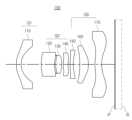
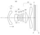
도 1는 본 발명의 제1실시 예에 따른 촬상 광학계의 구성도(광각상태)이다.
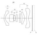
도 2는 본 발명의 제1실시 예에 따른 촬상 광학계의 구성도(망원상태)이다.
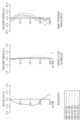
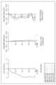
도 3은 도 1에 도시된 촬상 광학계의 수차 곡선이다.
도 4는 도 2에 도시된 촬상 광학계의 수차 곡선이다.
도 5는 본 발명의 제2실시 예에 따른 촬상 광학계의 구성도(광각상태)이다.
도 6은 본 발명의 제2실시 예에 따른 촬상 광학계의 구성도(망원상태)이다.
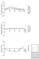
도 7은 도 5에 도시된 촬상 광학계의 수차 곡선이다.
도 8은 도 6에 도시된 촬상 광학계의 수차 곡선이다.
도 9는 본 발명의 제3실시 예에 따른 촬상 광학계의 구성도(광각상태)이다.
도 10은 본 발명의 제3실시 예에 따른 촬상 광학계의 구성도(망원상태)이다.
도 11은 도 9에 도시된 촬상 광학계의 수차 곡선이다.
도 12는 도 10에 도시된 촬상 광학계의 수차 곡선이다.
도 13은 본 발명의 제4실시 예에 따른 촬상 광학계의 구성도(광각상태)이다.
도 14는 본 발명의 제4실시 예에 따른 촬상 광학계의 구성도(망원상태)이다.
도 15는 도 13에 도시된 촬상 광학계의 수차 곡선이다.
도 16은 도 14에 도시된 촬상 광학계의 수차 곡선이다.
도 17은 일 실시 예에 따른 제7렌즈의 확대도이다.1 is a configuration diagram (wide-angle state) of an imaging optical system according to a first embodiment of the present invention.
2 is a configuration diagram (telescopic state) of an imaging optical system according to a first embodiment of the present invention.
3 is an aberration curve of the imaging optical system shown in FIG. 1;
FIG. 4 is an aberration curve of the imaging optical system shown in FIG. 2 .
5 is a configuration diagram (wide-angle state) of an imaging optical system according to a second embodiment of the present invention.
6 is a configuration diagram (telescopic state) of an imaging optical system according to a second embodiment of the present invention.
FIG. 7 is an aberration curve of the imaging optical system shown in FIG. 5 .
FIG. 8 is an aberration curve of the imaging optical system shown in FIG. 6 .
9 is a configuration diagram (wide-angle state) of an imaging optical system according to a third embodiment of the present invention.
10 is a configuration diagram (telescopic state) of an imaging optical system according to a third embodiment of the present invention.
FIG. 11 is an aberration curve of the imaging optical system shown in FIG. 9 .
12 is an aberration curve of the imaging optical system shown in FIG. 10;
13 is a configuration diagram (wide-angle state) of an imaging optical system according to a fourth embodiment of the present invention.
14 is a configuration diagram (telescopic state) of an imaging optical system according to a fourth embodiment of the present invention.
15 is an aberration curve of the imaging optical system shown in FIG. 13;
16 is an aberration curve of the imaging optical system shown in FIG. 14;
17 is an enlarged view of a seventh lens according to an exemplary embodiment.
이하, 본 발명의 바람직한 실시 예를 첨부된 예시도면에 의거하여 상세히 설명한다.Hereinafter, preferred embodiments of the present invention will be described in detail based on the accompanying drawings.
아래에서 본 발명을 설명함에 있어서, 본 발명의 구성요소를 지칭하는 용어들은 각각의 구성요소들의 기능을 고려하여 명명된 것이므로, 본 발명의 기술적 구성요소를 한정하는 의미로 이해되어서는 안 될 것이다.In describing the present invention below, terms referring to the components of the present invention are named in consideration of the functions of each component, so they should not be understood as limiting the technical components of the present invention.
아울러, 명세서 전체에서, 어떤 구성이 다른 구성과 '연결'되어 있다 함은 이들 구성들이 '직접적으로 연결'되어 있는 경우뿐만 아니라, 다른 구성을 사이에 두고 '간접적으로 연결'되어 있는 경우도 포함하는 것을 의미한다. 또한, 어떤 구성요소를 '포함'한다는 것은, 특별히 반대되는 기재가 없는 한 다른 구성요소를 제외하는 것이 아니라 다른 구성요소를 더 포함할 수 있다는 것을 의미한다.In addition, throughout the specification, that a component is 'connected' to another component includes not only the case where these components are 'directly connected', but also the case where they are 'indirectly connected' through other components. means that In addition, 'including' a certain component means that other components may be further included, rather than excluding other components unless otherwise stated.
본 명세서에서 제1렌즈는 물체(또는 피사체)와 가장 가까운 렌즈를 의미하고, 제7렌즈는 상면(또는 이미지 센서)과 가장 가까운 렌즈를 의미한다. 본 명세서에서 렌즈의 곡률 반지름(Radius), 두께(Thickness), TTL(제1렌즈의 물체 측면으로부터 상면까지 거리), 2ImgHT(상면의 대각길이), ImgHT(2ImgHT의 1/2), 초점거리의 단위는 ㎜이다.In this specification, the first lens refers to a lens closest to the object (or subject), and the seventh lens refers to a lens closest to the image surface (or image sensor). In this specification, the radius of curvature of the lens (Radius), thickness (Thickness), TTL (distance from the object side of the first lens to the image plane), 2ImgHT (diagonal length of the image plane), ImgHT (1/2 of 2ImgHT), focal length Unit is mm.
렌즈의 두께, 렌즈 간의 간격, TTL은 렌즈의 광축에서의 거리이다. 아울러, 렌즈의 형상에 대한 설명에서 일면이 볼록한 형상이라는 의미는 해당 면의 근축 부분(paraxial region)이 볼록하다는 의미이고, 일면이 오목한 형상이라는 의미는 해당 면의 근축 부분이 오목하다는 의미이다. 따라서, 렌즈의 일면이 볼록한 형상이라고 설명되어도, 렌즈의 가장자리 부분은 오목할 수 있다. 마찬가지로, 렌즈의 일면이 오목한 형상이라고 설명되어도, 렌즈의 가장자리 부분은 볼록할 수 있다.The thickness of the lens, the distance between the lenses, TTL is the distance from the optical axis of the lens. In addition, in the description of the shape of the lens, a convex shape on one surface means that a paraxial region of the corresponding surface is convex, and a concave shape means that the paraxial region of the corresponding surface is concave. Therefore, even if one surface of the lens is described as having a convex shape, the edge portion of the lens may be concave. Likewise, even if one surface of the lens is described as having a concave shape, the edge portion of the lens may be convex.
본 발명의 일 실시 예에 따른 촬상 광학계는 7매의 렌즈를 포함한다. 예를 들어, 촬상 광학계는 물체 측으로부터 순차적으로 배치되는 제1렌즈, 제2렌즈, 제3렌즈, 제4렌즈, 제5렌즈, 제6렌즈, 제7렌즈를 포함할 수 있다.An imaging optical system according to an embodiment of the present invention includes 7 lenses. For example, the imaging optical system may include a first lens, a second lens, a third lens, a fourth lens, a fifth lens, a sixth lens, and a seventh lens sequentially disposed from the object side.
일 실시 예에 따른 촬상 광학계는 박형화된 휴대 단말기에 장착되도록 구성될 수 있다. 예를 들어, 촬상 광학계의 최전방 렌즈(또는 제1렌즈)의 물체 측면으로부터 상면까지의 거리(TTL)는 6.0 mm보다 크고 9.0 mm 보다 작을 수 있다.An imaging optical system according to an embodiment may be configured to be mounted on a thin portable terminal. For example, the distance (TTL) from the side of the object to the image surface of the foremost lens (or first lens) of the imaging optical system may be greater than 6.0 mm and less than 9.0 mm.
일 실시 예에 따른 촬상 광학계는 대체로 넓은 화각을 갖도록 구성될 수 있다. 예를 들어, 촬상 광학계의 화각(FOV)은 85도보다 크고 160도보다 작을 수 있다.An imaging optical system according to an embodiment may be configured to have a substantially wide angle of view. For example, the field of view (FOV) of the imaging optical system may be greater than 85 degrees and less than 160 degrees.
본 발명은 전술된 실시 예와 다른 형태로도 구성될 수 있다.The present invention may also be configured in a form different from the above-described embodiment.
일 예로, 제1형태 예에 따른 촬상 광학계는 물체 측으로부터 순차적으로 배치되는 제1렌즈, 제2렌즈, 제3렌즈, 제4렌즈, 제5렌즈, 제6렌즈, 제7렌즈를 포함한다. 본 실시 예에 따른 촬상 광학계는 부의 굴절력을 갖는 복수의 렌즈를 포함한다. 예를 들어, 본 실시 예에 따른 촬상 광학계에서 제1렌즈, 제2렌즈, 제7렌즈는 부의 굴절력을 가질 수 있다.For example, the imaging optical system according to the first aspect includes a first lens, a second lens, a third lens, a fourth lens, a fifth lens, a sixth lens, and a seventh lens sequentially disposed from the object side. An imaging optical system according to this embodiment includes a plurality of lenses having negative refractive power. For example, in the imaging optical system according to the present embodiment, the first lens, the second lens, and the seventh lens may have negative refractive power.
본 형태에 따른 촬상 광학계는 일 측면이 볼록한 렌즈와 일 측면이 오목한 렌즈를 포함할 수 있다. 예를 들어, 촬상 광학계에서 제1렌즈는 물체 측면이 볼록한 형상이고, 제4렌즈는 상 측면이 오목한 형상이고, 제6렌즈는 물체 측면이 오목한 형상일 수 있다.An imaging optical system according to the present embodiment may include a lens having a convex side and a lens having a concave side. For example, in the imaging optical system, the first lens may have a convex object side surface, the fourth lens may have a concave image side surface, and the sixth lens may have a concave object side surface.
다른 예로, 제2형태에 따른 촬상 광학계는 초점조정(AF) 및 초점배율(Zoom)이 가능하도록 구성될 수 있다. 예를 들어, 촬상 광학계는 물체 측으로부터 순차적으로 배치되는 제1렌즈 군, 제2렌즈 군, 제3렌즈 군을 포함하고, 제1렌즈 군 및 제2렌즈 군의 위치변경을 통해 초점조정 및 초점배율이 가능하도록 구성될 수 있다.As another example, the imaging optical system according to the second aspect may be configured to enable focus adjustment (AF) and focus magnification (Zoom). For example, the imaging optical system includes a first lens group, a second lens group, and a third lens group that are sequentially disposed from the object side, and focus adjustment and focusing are performed through position changes of the first lens group and the second lens group. It can be configured to enable magnification.
본 형태에 따른 촬상 광학계는 서로 다른 크기의 초점거리와 화각을 가질 수 있다. 일 예로, 촬상 광학계는 130도 이상의 화각을 가질 수 있다. 다른 예로, 촬상 광학계는 95도 미만의 화각을 가질 수 있다. 전자의 따른 촬상 광학계의 초점거리는 후자에 따른 촬상 광학계의 초점거리보다 작을 수 있다.The imaging optical system according to the present embodiment may have different focal lengths and angles of view. For example, the imaging optical system may have an angle of view of 130 degrees or more. As another example, the imaging optical system may have an angle of view of less than 95 degrees. A focal length of the imaging optical system according to the former may be smaller than that of the imaging optical system according to the latter.
본 형태에 따른 촬상 광학계에서 각각의 렌즈 군은 하나 이상의 렌즈를 포함할 수 있다. 일 예로, 제1렌즈 군은 1매의 렌즈를 포함하고, 제2렌즈 군은 3매의 렌즈를 포함하고, 제3렌즈 군은 3매의 렌즈를 포함하도록 구성될 수 있다.In the imaging optical system according to the present embodiment, each lens group may include one or more lenses. For example, the first lens group may include one lens, the second lens group may include three lenses, and the third lens group may include three lenses.
촬상 광학계에서 제1렌즈 군 내지 제3렌즈 군은 소정의 굴절력을 가질 수 있다. 일 예로, 제렌즈 군은 부의 굴절력을 가지며, 제2렌즈 군은 정의 굴절력을 가지며, 제3렌즈 군은 정 또는 부의 굴절력을 가질 수 있다.In the imaging optical system, the first to third lens groups may have a predetermined refractive power. For example, the first lens group may have negative refractive power, the second lens group may have positive refractive power, and the third lens group may have positive or negative refractive power.
촬상 광학계는 제1렌즈 군 및 제2렌즈 군의 이동을 통해 화각을 변경할 수 있다. 일 예로, 촬상 광학계는 제1렌즈 군을 상면 방향으로 이동시키고, 제2렌즈 군을 물체 측으로 이동시켜 95도 미만의 화각을 구현할 수 있다. 다른 예로, 촬상 광학계는 제2렌즈 군을 물체 측으로 이동시키고, 제2렌즈 군을 상면 방향으로 이동시켜 120도 이상의 화각을 구현할 수 있다.The imaging optical system may change the angle of view by moving the first lens group and the second lens group. For example, the imaging optical system may implement a field of view of less than 95 degrees by moving the first lens group in the image plane direction and moving the second lens group toward the object. As another example, the imaging optical system may implement a field of view of 120 degrees or more by moving the second lens group toward the object and moving the second lens group toward the image plane.
또 다른 예로, 제3형태에 따른 촬상 광학계는 물체 측으로부터 순차적으로 배치되는 제1렌즈, 제2렌즈, 제3렌즈, 제4렌즈, 제5렌즈, 제6렌즈, 제7렌즈를 포함한다. 본 형태에 따른 촬상 광학계는 특유의 조건식을 만족할 수 있다. 예를 들어, 촬상 광학계는 하기 조건식 중 하나 이상을 만족할 수 있다.As another example, the imaging optical system according to the third aspect includes a first lens, a second lens, a third lens, a fourth lens, a fifth lens, a sixth lens, and a seventh lens sequentially disposed from the object side. The imaging optical system according to this aspect can satisfy a unique conditional expression. For example, the imaging optical system may satisfy one or more of the following conditional expressions.
25 < FOVw/fw < 6025 < FOVw/fw < 60
15 < FOVw/TTLw < 2515 < FOVw/TTLw < 25
2.0 < D12/D45 < 172.0 < D12/D45 < 17
1.0 < TTLw/TTLt < 1.11.0 < TTLw/TTLt < 1.1
-0.1 < ImgHT/fG3 < 0.2-0.1 < ImgHT/fG3 < 0.2
0.6 < R1/ImgHT < 0.70.6 < R1/ImgHT < 0.7
1.2 < VG2/VG3 < 1.31.2 < VG2/VG3 < 1.3
0.5 < d0S14/ImgHT < 0.850.5 < d0S14/ImgHT < 0.85
0.9 < SagS14/T7 < 1.30.9 < SagS14/T7 < 1.3
-0.7 < G1m/G2m < -0.4-0.7 < G1m/G2m < -0.4
상기 조건식에서 FOVw는 촬상 광학계의 광각 모드에서의 화각(참고로, FOVt는 망원모드에서의 화각임)이고, fw는 촬상 광학계의 광각 모드에서의 초점거리이고, ft는 촬상 광학계의 망원 모드에서의 초점거리이고, Lw는 촬상 광학계의 광각 모드에서의 상기 제1렌즈의 물체 측면으로부터 상기 상면까지의 거리이고, D12는 상기 제1렌즈의 상 측면으로부터 상기 제2렌즈의 물체 측면까지의 거리이고, D45는 상기 제4렌즈의 상 측면으로부터 상기 제5렌즈의 물체 측면까지의 거리이고, TTLw는 촬상 광학계의 광각 모드에서의 TTL(제1렌즈의 물체 측면으로부터 상면까지의 거리)이고, TTLt는 촬상 광학계의 망원 모드에서의 TTL(제1렌즈의 물체 측면으로부터 상면까지의 거리)이고, ImgHT는 상면의 높이이고, fG3은 상기 제5렌즈 내지 상기 제7렌즈의 합성 초점거리이고, R1은 상기 제1렌즈의 물체 측면의 곡률반지름이고, VG2는 상기 제2렌즈 내지 상기 제4렌즈의 아베수의 평균이고, VG3은 상기 제5렌즈 내지 상기 제7렌즈의 아베수의 평균이고, d0S14는 제7렌즈의 상 측면에 대한 1차 미분값이 0이 되는 지점에서 제7렌즈의 상 측면의 정점까지의 거리이고, SagS14는 제7렌즈의 상 측면에서 1차 미분값이 0이 되는 지점에서의 sag값이고, T7은 제7렌즈의 광축 중심에서의 두께이고, G1m은 제1렌즈 군이 광각 모드에서 망원 모드로 변경될 때 이동되는 거리이고, G2m은 제2렌즈 군이 광각 모드에서 망원 모드로 변경될 때 이동되는 거리이다. 참고로, T7, d0S14, 및 SagS14는 도 17에 표시된 부분을 의미할 수 있다.In the above conditional expression, FOVw is the angle of view in the wide-angle mode of the imaging optics (for reference, FOVt is the angle of view in the telephoto mode), fw is the focal length in the wide-angle mode of the imaging optics, and ft is the angle of view in the telephoto mode of the imaging optics is the focal length, Lw is the distance from the object side of the first lens to the image plane in the wide-angle mode of the imaging optical system, D12 is the distance from the image side of the first lens to the object side of the second lens, D45 is the distance from the image side of the fourth lens to the object side of the fifth lens, TTLw is the TTL (distance from the object side of the first lens to the image plane) in the wide-angle mode of the imaging optical system, and TTLt is the image TTL (distance from the object side of the first lens to the image plane) in the telephoto mode of the optical system, ImgHT is the height of the image plane, fG3 is the combined focal length of the 5th to 7th lenses, and R1 is the focal length of the 1st lens. The radius of curvature of the object side of
촬상 광학계는 하기 조건식 중 하나 이상을 만족할 수 있다.The imaging optical system may satisfy one or more of the following conditional expressions.
0.61 < R1/ImgHT < 0.900.61 < R1/ImgHT < 0.90
0.7 < SagS14/T7 < 1.80.7 < SagS14/T7 < 1.8
본 발명의 일 실시 예 내지 다른 실시 예에 따른 촬상 광학계는 필요에 따라 하기 특징을 갖는 렌즈를 하나 이상 포함할 수 있다. 일 예로, 일 실시 예에 따른 촬상 광학계는 하기 특징에 따른 제1렌즈 내지 제7렌즈 중 하나 이상을 포함할 수 있다. 다른 예로, 다른 실시 예에 따른 촬상 광학계는 하기 특징에 따른 제1렌즈 내지 제7렌즈 중 2개 이상을 포함할 수도 있다. 그러나 본 발명의 일 실시 예 내지 다른 실시 예에 따른 촬상 광학계가 하기 특징에 따른 렌즈를 반드시 포함하는 것은 아니다.An imaging optical system according to one embodiment or another embodiment of the present invention may include one or more lenses having the following characteristics as needed. For example, an imaging optical system according to an embodiment may include one or more of the first to seventh lenses according to the following characteristics. As another example, an imaging optical system according to another embodiment may include two or more of the first to seventh lenses according to the following characteristics. However, an imaging optical system according to one embodiment or another embodiment of the present invention does not necessarily include a lens according to the following characteristics.
이하에서 제1렌즈 내지 제7렌즈의 특징을 설명한다.Hereinafter, the characteristics of the first to seventh lenses will be described.
제1렌즈는 굴절력을 가진다. 예를 들어, 제1렌즈는 부의 굴절력을 가질 수 있다. 제1렌즈는 일면이 볼록한 형상이다. 예를 들어, 제1렌즈는 물체 측면이 볼록한 형상일 수 있다. 제1렌즈는 구면 또는 비구면을 포함한다. 일 예로, 제1렌즈의 양면은 모두 구면일 수 있다. 다른 예로, 제1렌즈의 적어도 일면은 비구면일 수 있다. 제1렌즈는 광 투과율이 높고 가공성이 우수한 재질로 제작될 수 있다. 예를 들어, 제1렌즈는 플라스틱 재질 또는 유리 재질로 제작될 수 있다. 제1렌즈는 높은 굴절률을 갖도록 구성될 수 있다. 일 예로, 제1렌즈의 굴절률은 1.7 보다 클 수 있다. 다른 예로, 제1렌즈의 굴절률은 1.70 보다 크고 1.90 보다 작을 수 있다. 제1렌즈는 소정의 아베수를 가질 수 있다. 일 예로, 제1렌즈의 아베수는 40 미만일 수 있다. 다른 예로, 제1렌즈의 아베수는 20 보다 크고 40 보다 작을 수 있다.The first lens has refractive power. For example, the first lens may have negative refractive power. The first lens has a shape in which one surface is convex. For example, the first lens may have a shape in which an object side surface is convex. The first lens includes a spherical surface or an aspheric surface. For example, both sides of the first lens may be spherical. As another example, at least one surface of the first lens may be an aspherical surface. The first lens may be made of a material having high light transmittance and excellent workability. For example, the first lens may be made of plastic or glass. The first lens may be configured to have a high refractive index. For example, the refractive index of the first lens may be greater than 1.7. As another example, the refractive index of the first lens may be greater than 1.70 and less than 1.90. The first lens may have a predetermined Abbe number. For example, the Abbe number of the first lens may be less than 40. As another example, the Abbe number of the first lens may be greater than 20 and less than 40.
제2렌즈는 굴절력을 가진다. 예를 들어, 제2렌즈는 부의 굴절력을 가질 수 있다. 제2렌즈는 일면이 볼록한 형상이다. 예를 들어, 제2렌즈는 물체 측면이 볼록한 형상일 수 있다. 제2렌즈는 구면 또는 비구면을 포함한다. 일 예로, 제2렌즈의 양면은 모두 구면일 수 있다. 다른 예로, 제2렌즈의 적어도 일면은 비구면일 수 있다. 제2렌즈는 광 투과율이 높고 가공성이 우수한 재질로 제작될 수 있다. 예를 들어, 제2렌즈는 플라스틱 재질 또는 유리 재질로 제작될 수 있다. 제2렌즈는 제1렌즈보다 큰 굴절률을 갖도록 구성될 수 있다. 일 예로, 제2렌즈의 굴절률은 1.9 보다 클 수 있다. 다른 예로, 제2렌즈의 굴절률은 1.90 보다 크고 2.0 보다 작을 수 있다. 제2렌즈는 소정의 아베수를 가질 수 있다. 일 예로, 제2렌즈의 아베수는 20 미만일 수 있다. 다른 예로, 제2렌즈의 아베수는 10 보다 크고 20 보다 작을 수 있다.The second lens has refractive power. For example, the second lens may have negative refractive power. The second lens has a convex shape on one surface. For example, the second lens may have a shape in which the side of the object is convex. The second lens includes a spherical surface or an aspherical surface. For example, both surfaces of the second lens may be spherical. As another example, at least one surface of the second lens may be an aspherical surface. The second lens may be made of a material having high light transmittance and excellent workability. For example, the second lens may be made of plastic material or glass material. The second lens may be configured to have a higher refractive index than the first lens. For example, the refractive index of the second lens may be greater than 1.9. As another example, the refractive index of the second lens may be greater than 1.90 and less than 2.0. The second lens may have a predetermined Abbe number. For example, the Abbe number of the second lens may be less than 20. As another example, the Abbe number of the second lens may be greater than 10 and less than 20.
제3렌즈는 굴절력을 가진다. 예를 들어, 제3렌즈는 정의 굴절력을 가질 수 있다. 제3렌즈는 일면이 볼록한 형상이다. 예를 들어, 제3렌즈는 상 측면이 볼록한 형상일 수 있다. 제3렌즈는 구면 또는 비구면을 포함한다. 일 예로, 제3렌즈의 양면은 모두 구면일 수 있다. 다른 예로, 제3렌즈의 적어도 일면은 비구면일 수 있다. 제3렌즈는 광 투과율이 높고 가공성이 우수한 재질로 제작될 수 있다. 예를 들어, 제3렌즈는 플라스틱 재질로 제작될 수 있다. 제3렌즈는 제1렌즈보다 작은 굴절률을 갖도록 구성될 수 있다. 일 예로, 제3렌즈의 굴절률은 1.6보다 작을 수 있다. 다른 예로, 제3렌즈의 굴절률은 1.5 보다 크고 1.6 보다 작을 수 있다. 제3렌즈는 소정의 아베수를 가질 수 있다. 일 예로, 제3렌즈의 아베수는 50 보다 클 수 있다. 다른 예로, 제3렌즈의 아베수는 50 보다 크고 70 보다 작을 수 있다.The third lens has refractive power. For example, the third lens may have positive refractive power. The third lens has a shape in which one surface is convex. For example, the third lens may have a convex image side surface. The third lens includes a spherical surface or an aspherical surface. For example, both surfaces of the third lens may be spherical. As another example, at least one surface of the third lens may be an aspherical surface. The third lens may be made of a material having high light transmittance and excellent workability. For example, the third lens may be made of a plastic material. The third lens may be configured to have a smaller refractive index than the first lens. For example, the refractive index of the third lens may be less than 1.6. As another example, the refractive index of the third lens may be greater than 1.5 and less than 1.6. The third lens may have a predetermined Abbe number. For example, the Abbe number of the third lens may be greater than 50. As another example, the Abbe number of the third lens may be greater than 50 and less than 70.
제4렌즈는 굴절력을 가진다. 예를 들어, 제4렌즈는 정의 굴절력을 가질 수 있다. 제4렌즈는 일면이 볼록한 형상이다. 예를 들어, 제4렌즈는 물체 측면이 볼록한 형상일 수 있다. 제4렌즈는 구면 또는 비구면을 포함한다. 일 예로, 제4렌즈의 양면은 모두 구면일 수 있다. 다른 예로, 제4렌즈의 적어도 일면은 비구면일 수 있다. 제4렌즈는 광 투과율이 높고 가공성이 우수한 재질로 제작될 수 있다. 예를 들어, 제4렌즈는 플라스틱 재질로 제작될 수 있다. 제4렌즈는 제1렌즈보다 작은 굴절률을 갖도록 구성될 수 있다. 일 예로, 제4렌즈의 굴절률은 1.6보다 작을 수 있다. 다른 예로, 제4렌즈의 굴절률은 1.5 보다 크고 1.6 보다 작을 수 있다. 제4렌즈는 소정의 아베수를 가질 수 있다. 일 예로, 제4렌즈의 아베수는 50 보다 클 수 있다. 다른 예로, 제4렌즈의 아베수는 50 보다 크고 70 보다 작을 수 있다.The fourth lens has refractive power. For example, the fourth lens may have positive refractive power. The fourth lens has a shape in which one surface is convex. For example, the fourth lens may have a shape in which an object side surface is convex. The fourth lens includes a spherical surface or an aspherical surface. For example, both sides of the fourth lens may be spherical. As another example, at least one surface of the fourth lens may be an aspherical surface. The fourth lens may be made of a material having high light transmittance and excellent workability. For example, the fourth lens may be made of a plastic material. The fourth lens may be configured to have a smaller refractive index than the first lens. For example, the refractive index of the fourth lens may be less than 1.6. As another example, the refractive index of the fourth lens may be greater than 1.5 and less than 1.6. The fourth lens may have a predetermined Abbe number. For example, the Abbe number of the fourth lens may be greater than 50. As another example, the Abbe number of the fourth lens may be greater than 50 and less than 70.
제5렌즈는 굴절력을 가진다. 예를 들어, 제5렌즈는 부의 굴절력을 가질 수 있다. 제5렌즈는 일면이 볼록한 형상이다. 예를 들어, 제5렌즈는 물체 측면이 볼록한 형상일 수 있다. 제5렌즈는 구면 또는 비구면을 포함한다. 일 예로, 제5렌즈의 양면은 모두 구면일 수 있다. 다른 예로, 제5렌즈의 적어도 일면은 비구면일 수 있다. 제5렌즈는 광 투과율이 높고 가공성이 우수한 재질로 제작될 수 있다. 예를 들어, 제5렌즈는 플라스틱 재질로 제작될 수 있다. 제5렌즈는 제3렌즈보다 큰 굴절률을 갖도록 구성될 수 있다. 일 예로, 제5렌즈의 굴절률은 1.6보다 클 수 있다. 다른 예로, 제5렌즈의 굴절률은 1.6 보다 크고 1.7 보다 작을 수 있다. 제5렌즈는 소정의 아베수를 가질 수 있다. 일 예로, 제5렌즈의 아베수는 20 보다 클 수 있다. 다른 예로, 제5렌즈의 아베수는 20 보다 크고 30 보다 작을 수 있다.The fifth lens has refractive power. For example, the fifth lens may have negative refractive power. The fifth lens has a shape in which one surface is convex. For example, the fifth lens may have a shape in which an object side surface is convex. The fifth lens includes a spherical surface or an aspherical surface. For example, both surfaces of the fifth lens may be spherical. As another example, at least one surface of the fifth lens may be an aspherical surface. The fifth lens may be made of a material having high light transmittance and excellent workability. For example, the fifth lens may be made of a plastic material. The fifth lens may be configured to have a higher refractive index than the third lens. For example, the refractive index of the fifth lens may be greater than 1.6. As another example, the refractive index of the fifth lens may be greater than 1.6 and less than 1.7. The fifth lens may have a predetermined Abbe number. For example, the Abbe number of the fifth lens may be greater than 20. As another example, the Abbe number of the fifth lens may be greater than 20 and less than 30.
제6렌즈는 굴절력을 가진다. 예를 들어, 제6렌즈는 정의 굴절력을 가질 수 있다. 제6렌즈는 일면이 볼록한 형상이다. 예를 들어, 제6렌즈는 상 측면이 볼록한 형상일 수 있다. 제6렌즈는 구면 또는 비구면을 포함한다. 일 예로, 제6렌즈의 양면은 모두 구면일 수 있다. 다른 예로, 제6렌즈의 적어도 일면은 비구면일 수 있다. 제6렌즈는 광 투과율이 높고 가공성이 우수한 재질로 제작될 수 있다. 예를 들어, 제6렌즈는 플라스틱 재질로 제작될 수 있다. 제6렌즈는 소정의 굴절률을 갖도록 구성될 수 있다. 일 예로, 제6렌즈의 굴절률은 1.6보다 작을 수 있다. 다른 예로, 제6렌즈의 굴절률은 1.5 보다 크고 1.6 보다 작을 수 있다. 제6렌즈는 소정의 아베수를 가질 수 있다. 일 예로, 제6렌즈의 아베수는 50 보다 클 수 있다. 다른 예로, 제6렌즈의 아베수는 50 보다 크고 70 보다 작을 수 있다.The sixth lens has refractive power. For example, the sixth lens may have positive refractive power. The sixth lens has a shape in which one surface is convex. For example, the sixth lens may have a convex image side surface. The sixth lens includes a spherical surface or an aspheric surface. For example, both sides of the sixth lens may be spherical. As another example, at least one surface of the sixth lens may be an aspherical surface. The sixth lens may be made of a material having high light transmittance and excellent workability. For example, the sixth lens may be made of a plastic material. The sixth lens may be configured to have a predetermined refractive index. For example, the refractive index of the sixth lens may be less than 1.6. As another example, the refractive index of the sixth lens may be greater than 1.5 and less than 1.6. The sixth lens may have a predetermined Abbe number. For example, the Abbe number of the sixth lens may be greater than 50. As another example, the Abbe number of the sixth lens may be greater than 50 and less than 70.
제7렌즈는 굴절력을 가진다. 예를 들어, 제7렌즈는 부의 굴절력을 가질 수 있다. 제7렌즈는 일면이 볼록한 형상이다. 예를 들어, 제7렌즈는 물체 측면이 볼록한 형상일 수 있다. 제7렌즈는 구면 또는 비구면을 포함한다. 일 예로, 제7렌즈의 적어도 일면은 구면이거나 또는 비구면일 수 있다. 제7렌즈는 광 투과율이 높고 가공성이 우수한 재질로 제작될 수 있다. 예를 들어, 제7렌즈는 플라스틱 재질로 제작될 수 있다. 제7렌즈는 제3렌즈보다 큰 굴절률을 갖도록 구성될 수 있다. 일 예로, 제7렌즈의 굴절률은 1.6보다 클 수 있다. 다른 예로, 제7렌즈의 굴절률은 1.6 보다 크고 1.7 보다 작을 수 있다. 제7렌즈는 소정의 아베수를 가질 수 있다. 일 예로, 제7렌즈의 아베수는 20 보다 클 수 있다. 다른 예로, 제7렌즈의 아베수는 20 보다 크고 30 보다 작을 수 있다. 제7렌즈는 특유의 형상을 포함할 수 있다. 예를 들어, 제7렌즈는 광축 중심부의 형상과 광축 주변부의 형상이 상이하도록 구성될 수 있다. 일 예로, 제7렌즈의 물체 측면은 광축 중심부에서 볼록하고 광축 주변부에서 오목한 형상일 수 있다. 다른 예로, 제7렌즈의 상 측면은 광축 중심부에서 오목하고 광축 주변부에서 볼록한 형상일 수 있다. 아울러, 제7렌즈는 물체 측면 및 상 측면 중 적어도 일면에 변곡점이 형성되는 형상일 수 있다.The seventh lens has refractive power. For example, the seventh lens may have negative refractive power. The seventh lens has a shape in which one surface is convex. For example, the seventh lens may have a shape in which an object side surface is convex. The seventh lens includes a spherical surface or an aspheric surface. For example, at least one surface of the seventh lens may be a spherical surface or an aspheric surface. The seventh lens may be made of a material having high light transmittance and excellent workability. For example, the seventh lens may be made of a plastic material. The seventh lens may be configured to have a higher refractive index than the third lens. For example, the refractive index of the seventh lens may be greater than 1.6. As another example, the refractive index of the seventh lens may be greater than 1.6 and less than 1.7. The seventh lens may have a predetermined Abbe number. For example, the Abbe number of the seventh lens may be greater than 20. As another example, the Abbe number of the seventh lens may be greater than 20 and less than 30. The seventh lens may include a unique shape. For example, the seventh lens may be configured such that the shape of the center of the optical axis and the shape of the peripheral portion of the optical axis are different. For example, the object side surface of the seventh lens may be convex at the center of the optical axis and concave at the periphery of the optical axis. As another example, the image side surface of the seventh lens may be concave at the center of the optical axis and convex at the periphery of the optical axis. In addition, the seventh lens may have a shape in which an inflection point is formed on at least one of the object side and the image side.
제1렌즈 내지 제7렌즈는 전술한 바와 같이 구면 또는 비구면을 포함할 수 있다. 제1렌즈 내지 제7렌즈가 비구면을 포함할 경우, 해당 렌즈의 비구면은 수학식 1로 표현될 수 있다.As described above, the first to seventh lenses may include a spherical surface or an aspherical surface. When the first to seventh lenses include an aspheric surface, the aspherical surface of the corresponding lens may be expressed by

수학식 1에서 c는 해당 렌즈의 곡률 반지름의 역수이고, k는 코닉 상수이고, r은 비구면 상의 임의의 점으로부터 광축까지의 거리이고, A ~ J는 비구면 상수이고, Z(또는 SAG)는 비구면 상의 임의의 점으로부터 해당 비구면의 정점까지의 광축 방향으로의 높이이다.In
전술된 실시 예 또는 전술된 형태에 따른 촬상 광학계는 조리개, 필터를 더 포함할 수 있다. 일 예로, 촬상 광학계는 제2렌즈와 제3렌즈에 배치되는 조리개 또는 제2렌즈 군에 포함하되는 조리개를 더 포함할 수 있다. 다른 예로, 촬상 광학계는 최후방 렌즈(제7렌즈 또는 제3렌즈 군)와 상면 사이에 배치되는 필터를 더 포함할 수 있다. 조리개는 상면 방향으로 입사되는 광량을 조절하도록 구성되고, 필터는 특정 파장의 빛을 차단하도록 구성될 수 있다. 참고로, 본 명세서에 기술된 필터는 적외선을 차단하도록 구성되나, 필터를 통해 차단되는 파장의 빛이 적외선으로 한정되는 것은 아니다.The imaging optical system according to the above-described embodiment or the above-described form may further include a diaphragm and a filter. For example, the imaging optical system may further include a diaphragm disposed in the second lens and the third lens or a diaphragm included in the second lens group. As another example, the imaging optical system may further include a filter disposed between the rearmost lens (the seventh lens or the third lens group) and the image surface. The diaphragm may be configured to adjust the amount of light incident in the direction of the upper surface, and the filter may be configured to block light of a specific wavelength. For reference, the filter described herein is configured to block infrared rays, but the wavelength of light blocked through the filter is not limited to infrared rays.
다음에서는 도면을 참조하여 구체적인 실시 예에 따른 촬상 광학계를 설명한다.Next, an imaging optical system according to specific embodiments will be described with reference to the drawings.
먼저, 도 1 및 도 2를 참조하여 제1실시 예에 따른 촬상 광학계를 설명한다.First, the imaging optical system according to the first embodiment will be described with reference to FIGS. 1 and 2 .
촬상 광학계(100)는 제1렌즈(110), 제2렌즈(120), 제3렌즈(130), 제4렌즈(140), 제5렌즈(150), 제6렌즈(160), 제7렌즈(170)를 포함한다.The imaging
제1렌즈(110)는 부의 굴절력을 가지며, 물체 측면이 볼록하고 상 측면이 오목한 형상이다. 제2렌즈(120)는 부의 굴절력을 가지며, 물체 측면이 볼록하고 상 측면이 오목한 형상이다. 제3렌즈(130)는 정의 굴절력을 가지며, 물체 측면이 볼록하고 상 측면이 볼록한 형상이다. 제4렌즈(140)는 정의 굴절력을 가지며, 물체 측면이 볼록하고 상 측면이 오목한 형상이다. 제5렌즈(150)는 부의 굴절력을 가지며, 물체 측면이 볼록하고 상 측면이 오목한 형상이다. 제6렌즈(160)는 정의 굴절력을 가지며, 물체 측면이 오목하고 상 측면이 볼록한 형상이다. 제7렌즈(170)는 부의 굴절력을 가지며, 물체 측면이 볼록하고 상 측면이 오목한 형상이다. 아울러, 제7렌즈(170)는 물체 측면 및 상 측면에 변곡점이 형성되는 형상이다. 부연 설명하면, 제7렌즈(170)의 물체 측면은 광축 중심부분에서 볼록하고 광축 주변부에서 오목한 형상이다. 아울러, 제7렌즈(170)의 상 측면은 광축 중심부분에서 오목하고 광축 주변부에서 볼록한 형상이다.The
제1렌즈(110) 내지 제7렌즈(170)는 복수의 렌즈 군으로 구별될 수 있다. 일 예로, 제1렌즈(110)는 제1렌즈 군(G1)을 구성하고, 제2렌즈(120) 내지 제4렌즈(140)는 제2렌즈 군(G2)을 구성하고, 제5렌즈(150) 내지 제7렌즈(170)는 제3렌즈 군(G3)을 구성할 수 있다.The
촬상 광학계(100)에서 제1렌즈(110) 내지 제7렌즈(170) 중 하나 이상은 광축 방향으로 이동가능하도록 구성될 수 있다. 예를 들어, 제1렌즈 군(G1) 및 제2렌즈 군(G2)을 구성하는 렌즈들(110, 120, 130, 140)은 광축 방향을 따라 이동되도록 구성될 수 있다.In the imaging
촬상 광학계(100)는 초점조정(AF) 및 초점배율조정(Zoom)이 가능하도록 구성될 수 있다. 일 예로, 촬상 광학계(100)는 제1렌즈 군(G1) 및 제2렌즈 군(G2) 중 하나 이상을 광축 방향으로 소폭 이동시켜 초점조정을 수행할 수 있다. 다른 예로, 촬상 광학계(100)는 제1렌즈 군(G1) 및 제2렌즈 군(G2) 모두를 광축 방향으로 이동시켜 초점배율조정을 수행할 수 있다. 참고로, 촬상 광학계(100)의 초점조정(AF) 및 초점배율조정(Zoom) 수행 시 제3렌즈 군(G3)은 이동하지 않을 수 있으나, 촬상 광학계(100)의 해상도를 향상시키기 상당히 미미한 크기로 이동될 수도 있다.The imaging
촬상 광학계(100)는 조리개(ST), 필터(도시되지 않음), 상면(IP)를 더 포함할 수 있다. 예를 들어, 조리개(ST)는 제2렌즈(120)와 제3렌즈(130) 사이에 배치되고, 필터는 제7렌즈(170)와 상면(IP) 사이에 배치될 수 있다. 그러나 촬상 광학계(100)가 조리개(ST) 및 필터를 반드시 포함하는 것은 아니다. 예를 들어, 조리개(ST) 또는 필터는 필요에 따라 생략될 수 있다. 상면(IP)은 제1렌즈(110) 내지 제7렌즈(170)에 의해 입사되는 빛이 결상되는 위치에 형성될 수 있다. 예를 들어, 상면(IP)은 카메라 모듈의 이미지 센서(IS)의 일면 또는 이미지 센서(IS)의 내부에 배치되는 광소자 상에 형성될 수 있다.The imaging
본 실시 예에 따른 촬상 광학계(100)는 2개의 촬상 모드를 구현할 수 있다. 일 예로, 촬상 광학계(100)는 도 1에 도시된 형태를 통해 제1촬상 모드(또는 광각 모드)를 구현할 수 있다. 다른 예로, 촬상 광학계(100)는 도 2에 도시된 형태를 통해 제2촬상 모드(또는 망원 모드)를 구현할 수 있다. 제1촬상 모드에서 제2촬상 모드로의 변경 및 제2촬상 모드에서 제1촬상 모드로의 변경은 제1렌즈 군(G1)과 제2렌즈 군(G2)의 위치변경을 통해 이루어질 수 있다. 일 예로, 제2촬상 모드에 따른 촬상 광학계(100)는, 제1촬상 모드에 따른 촬상 광학계(100)에서 제1렌즈 군(G1)을 상면 방향으로 이동시키고 제2렌즈 군(G2)을 물체 측으로 이동시킴으로써, 구현될 수 있다. 다른 예로, 제1촬상 모드에 따른 촬상 광학계(100)는, 제2촬상 모드에 따른 촬상 광학계(100)에서 제1렌즈 군(G1)을 물체 측으로 이동시키고 제2렌즈 군(G2)을 상면 방향으로 이동시킴으로써, 구현될 수 있다.The imaging
다음에서는 각 촬상 모드에 따른 특징을 설명한다.Next, features of each imaging mode will be described.
제1촬상 모드에 따른 촬상 광학계(100)는 120도 이상의 화각을 가질 수 있다. 예를 들어, 제1촬상 모드에 따른 촬상 광학계(100)는 140도의 화각을 가질 수 있다. 제1촬상 모드에 따른 촬상 광학계(100)는 대체로 근거리에 위치한 피사체를 촬상할 수 있다.The imaging
촬상 광학계(100)는 제1촬상 모드의 상태에서 초점조정을 수행할 수 있다. 예를 들어, 촬상 광학계(100)는 제1렌즈 군(G1) 및 제2렌즈 군(G2) 중 하나 이상을 광축 방향으로 소폭 이동시켜 초점조정을 수행할 수 있다.The imaging
제2촬상 모드에 따른 촬상 광학계(100)는 95도 이하의 화각을 가질 수 있다. 예를 들어, 제2촬상 모드에 따른 촬상 광학계(100)는 90도의 화각을 가질 수 있다. 제2촬상 모드에 따른 촬상 광학계(100)는 대체로 근거리에 위치한 피사체를 촬상할 수 있다.The imaging
촬상 광학계(100)는 제2촬상 모드의 상태에서 초점조정을 수행할 수 있다. 예를 들어, 촬상 광학계(100)는 제1렌즈 군(G1) 및 제2렌즈 군(G2) 중 하나 이상을 광축 방향으로 소폭 이동시켜 초점조정을 수행할 수 있다.The imaging
위와 같이 구성된 촬상 광학계(100)는 도 3 및 도 4에 도시된 바와 같이 서로 다른 수차 특성을 나타낸다. 표 1 내지 표 3은 본 실시 예에 따른 촬상 광학계의 렌즈 특성 및 비구면 값을 나타낸다.The imaging
(표 3에서 rN은 제7렌즈의 유효지름을 의미한다)(In Table 3, rN means the effective diameter of the seventh lens)
도 5 및 도 6를 참조하여 제2실시 예에 따른 촬상 광학계를 설명한다.An imaging optical system according to a second embodiment will be described with reference to FIGS. 5 and 6 .
촬상 광학계(200)는 제1렌즈(210), 제2렌즈(220), 제3렌즈(230), 제4렌즈(240), 제5렌즈(250), 제6렌즈(260), 제7렌즈(270)를 포함한다.The imaging
제1렌즈(210)는 부의 굴절력을 가지며, 물체 측면이 볼록하고 상 측면이 오목한 형상이다. 제2렌즈(220)는 부의 굴절력을 가지며, 물체 측면이 볼록하고 상 측면이 오목한 형상이다. 제3렌즈(230)는 정의 굴절력을 가지며, 물체 측면이 볼록하고 상 측면이 볼록한 형상이다. 제4렌즈(240)는 정의 굴절력을 가지며, 물체 측면이 볼록하고 상 측면이 오목한 형상이다. 제5렌즈(250)는 부의 굴절력을 가지며, 물체 측면이 볼록하고 상 측면이 오목한 형상이다. 제6렌즈(260)는 정의 굴절력을 가지며, 물체 측면이 오목하고 상 측면이 볼록한 형상이다. 제7렌즈(270)는 부의 굴절력을 가지며, 물체 측면이 볼록하고 상 측면이 오목한 형상이다. 아울러, 제7렌즈(270)는 물체 측면 및 상 측면에 변곡점이 형성되는 형상이다. 부연 설명하면, 제7렌즈(270)의 물체 측면은 광축 중심부분에서 볼록하고 광축 주변부에서 오목한 형상이다. 아울러, 제7렌즈(270)의 상 측면은 광축 중심부분에서 오목하고 광축 주변부에서 볼록한 형상이다.The
제1렌즈(210) 내지 제7렌즈(270)는 복수의 렌즈 군으로 구별될 수 있다. 일 예로, 제1렌즈(210)는 제1렌즈 군(G1)을 구성하고, 제2렌즈(220) 내지 제4렌즈(240)는 제2렌즈 군(G2)을 구성하고, 제5렌즈(250) 내지 제7렌즈(270)는 제3렌즈 군(G3)을 구성할 수 있다.The
촬상 광학계(200)에서 제1렌즈(210) 내지 제7렌즈(270) 중 하나 이상은 광축 방향으로 이동가능하도록 구성될 수 있다. 예를 들어, 제1렌즈 군(G1) 및 제2렌즈 군(G2)을 구성하는 렌즈들(210, 220, 230, 240)은 광축 방향을 따라 이동되도록 구성될 수 있다.In the imaging
촬상 광학계(200)는 초점조정(AF) 및 초점배율조정(Zoom)이 가능하도록 구성될 수 있다. 일 예로, 촬상 광학계(200)는 제1렌즈 군(G1) 및 제2렌즈 군(G2) 중 하나 이상을 광축 방향으로 소폭 이동시켜 초점조정을 수행할 수 있다. 다른 예로, 촬상 광학계(200)는 제1렌즈 군(G1) 및 제2렌즈 군(G2) 모두를 광축 방향으로 이동시켜 초점배율조정을 수행할 수 있다. 참고로, 촬상 광학계(200)의 초점조정(AF) 및 초점배율조정(Zoom) 수행 시 제3렌즈 군(G3)은 이동하지 않을 수 있으나, 촬상 광학계(200)의 해상도를 향상시키기 상당히 미미한 크기로 이동될 수도 있다.The imaging
촬상 광학계(200)는 조리개(ST), 필터(도시되지 않음), 상면(IP)를 더 포함할 수 있다. 예를 들어, 조리개(ST)는 제2렌즈(220)와 제3렌즈(230) 사이에 배치되고, 필터는 제7렌즈(270)와 상면(IP) 사이에 배치될 수 있다. 그러나 촬상 광학계(200)가 조리개(ST) 및 필터를 반드시 포함하는 것은 아니다. 예를 들어, 조리개(ST) 또는 필터는 필요에 따라 생략될 수 있다. 상면(IP)은 제1렌즈(210) 내지 제7렌즈(270)에 의해 입사되는 빛이 결상되는 위치에 형성될 수 있다. 예를 들어, 상면(IP)은 카메라 모듈의 이미지 센서(IS)의 일면 또는 이미지 센서(IS)의 내부에 배치되는 광소자 상에 형성될 수 있다.The imaging
본 실시 예에 따른 촬상 광학계(200)는 2개의 촬상 모드를 구현할 수 있다. 일 예로, 촬상 광학계(200)는 도 5에 도시된 형태를 통해 제1촬상 모드(또는 광각 모드)를 구현할 수 있다. 다른 예로, 촬상 광학계(200)는 도 6에 도시된 형태를 통해 제2촬상 모드(또는 망원 모드)를 구현할 수 있다. 제1촬상 모드에서 제2촬상 모드로의 변경 및 제2촬상 모드에서 제1촬상 모드로의 변경은 제1렌즈 군(G1)과 제2렌즈 군(G2)의 위치변경을 통해 이루어질 수 있다. 일 예로, 제2촬상 모드에 따른 촬상 광학계(200)는, 제1촬상 모드에 따른 촬상 광학계(200)에서 제1렌즈 군(G1)을 상면 방향으로 이동시키고 제2렌즈 군(G2)을 물체 측으로 이동시킴으로써, 구현될 수 있다. 다른 예로, 제1촬상 모드에 따른 촬상 광학계(200)는, 제2촬상 모드에 따른 촬상 광학계(200)에서 제1렌즈 군(G1)을 물체 측으로 이동시키고 제2렌즈 군(G2)을 상면 방향으로 이동시킴으로써, 구현될 수 있다.The imaging
다음에서는 각 촬상 모드에 따른 특징을 설명한다.Next, features of each imaging mode will be described.
제1촬상 모드에 따른 촬상 광학계(200)는 120도 이상의 화각을 가질 수 있다. 예를 들어, 제1촬상 모드에 따른 촬상 광학계(200)는 140도의 화각을 가질 수 있다. 제1촬상 모드에 따른 촬상 광학계(200)는 대체로 근거리에 위치한 피사체를 촬상할 수 있다.The imaging
촬상 광학계(200)는 제1촬상 모드의 상태에서 초점조정을 수행할 수 있다. 예를 들어, 촬상 광학계(200)는 제1렌즈 군(G1) 및 제2렌즈 군(G2) 중 하나 이상을 광축 방향으로 소폭 이동시켜 초점조정을 수행할 수 있다.The imaging
제2촬상 모드에 따른 촬상 광학계(200)는 95도 이하의 화각을 가질 수 있다. 예를 들어, 제2촬상 모드에 따른 촬상 광학계(200)는 90도의 화각을 가질 수 있다. 제2촬상 모드에 따른 촬상 광학계(200)는 대체로 근거리에 위치한 피사체를 촬상할 수 있다.The imaging
촬상 광학계(200)는 제2촬상 모드의 상태에서 초점조정을 수행할 수 있다. 예를 들어, 촬상 광학계(200)는 제1렌즈 군(G1) 및 제2렌즈 군(G2) 중 하나 이상을 광축 방향으로 소폭 이동시켜 초점조정을 수행할 수 있다.The imaging
위와 같이 구성된 촬상 광학계(200)는 도 7 및 도 8에 도시된 바와 같이 서로 다른 수차 특성을 나타낸다. 표 4 내지 표 6은 본 실시 예에 따른 촬상 광학계의 렌즈 특성 및 비구면 값을 나타낸다.The imaging
(표 6에서 rN은 제7렌즈의 유효지름을 의미한다)(In Table 6, rN means the effective diameter of the seventh lens)
도 9 및 도 10을 참조하여 제3실시 예에 따른 촬상 광학계를 설명한다.An imaging optical system according to a third embodiment will be described with reference to FIGS. 9 and 10 .
촬상 광학계(300)는 제1렌즈(310), 제2렌즈(320), 제3렌즈(330), 제4렌즈(340), 제5렌즈(350), 제6렌즈(360), 제7렌즈(370)를 포함한다.The imaging
제1렌즈(310)는 부의 굴절력을 가지며, 물체 측면이 볼록하고 상 측면이 오목한 형상이다. 제2렌즈(320)는 부의 굴절력을 가지며, 물체 측면이 볼록하고 상 측면이 오목한 형상이다. 제3렌즈(330)는 정의 굴절력을 가지며, 물체 측면이 볼록하고 상 측면이 볼록한 형상이다. 제4렌즈(340)는 정의 굴절력을 가지며, 물체 측면이 볼록하고 상 측면이 오목한 형상이다. 제5렌즈(350)는 부의 굴절력을 가지며, 물체 측면이 볼록하고 상 측면이 오목한 형상이다. 제6렌즈(360)는 정의 굴절력을 가지며, 물체 측면이 오목하고 상 측면이 볼록한 형상이다. 제7렌즈(370)는 부의 굴절력을 가지며, 물체 측면이 볼록하고 상 측면이 오목한 형상이다. 아울러, 제7렌즈(370)는 물체 측면 및 상 측면에 변곡점이 형성되는 형상이다. 부연 설명하면, 제7렌즈(370)의 물체 측면은 광축 중심부분에서 볼록하고 광축 주변부에서 오목한 형상이다. 아울러, 제7렌즈(370)의 상 측면은 광축 중심부분에서 오목하고 광축 주변부에서 볼록한 형상이다.The
제1렌즈(310) 내지 제7렌즈(370)는 복수의 렌즈 군으로 구별될 수 있다. 일 예로, 제1렌즈(310)는 제1렌즈 군(G1)을 구성하고, 제2렌즈(320) 내지 제4렌즈(340)는 제2렌즈 군(G2)을 구성하고, 제5렌즈(350) 내지 제7렌즈(370)는 제3렌즈 군(G3)을 구성할 수 있다.The
촬상 광학계(300)에서 제1렌즈(310) 내지 제7렌즈(370) 중 하나 이상은 광축 방향으로 이동가능하도록 구성될 수 있다. 예를 들어, 제1렌즈 군(G1) 및 제2렌즈 군(G2)을 구성하는 렌즈들(310, 320, 330, 340)은 광축 방향을 따라 이동되도록 구성될 수 있다.In the imaging
촬상 광학계(300)는 초점조정(AF) 및 초점배율조정(Zoom)이 가능하도록 구성될 수 있다. 일 예로, 촬상 광학계(300)는 제1렌즈 군(G1) 및 제2렌즈 군(G2) 중 하나 이상을 광축 방향으로 소폭 이동시켜 초점조정을 수행할 수 있다. 다른 예로, 촬상 광학계(300)는 제1렌즈 군(G1) 및 제2렌즈 군(G2) 모두를 광축 방향으로 이동시켜 초점배율조정을 수행할 수 있다. 참고로, 촬상 광학계(300)의 초점조정(AF) 및 초점배율조정(Zoom) 수행 시 제3렌즈 군(G3)은 이동하지 않을 수 있으나, 촬상 광학계(300)의 해상도를 향상시키기 상당히 미미한 크기로 이동될 수도 있다.The imaging
촬상 광학계(300)는 조리개(ST), 필터(도시되지 않음), 상면(IP)를 더 포함할 수 있다. 예를 들어, 조리개(ST)는 제2렌즈(320)와 제3렌즈(330) 사이에 배치되고, 필터는 제7렌즈(370)와 상면(IP) 사이에 배치될 수 있다. 그러나 촬상 광학계(300)가 조리개(ST) 및 필터를 반드시 포함하는 것은 아니다. 예를 들어, 조리개(ST) 또는 필터는 필요에 따라 생략될 수 있다. 상면(IP)은 제1렌즈(310) 내지 제7렌즈(370)에 의해 입사되는 빛이 결상되는 위치에 형성될 수 있다. 예를 들어, 상면(IP)은 카메라 모듈의 이미지 센서(IS)의 일면 또는 이미지 센서(IS)의 내부에 배치되는 광소자 상에 형성될 수 있다.The imaging
본 실시 예에 따른 촬상 광학계(300)는 2개의 촬상 모드를 구현할 수 있다. 일 예로, 촬상 광학계(300)는 도 5에 도시된 형태를 통해 제1촬상 모드(또는 광각 모드)를 구현할 수 있다. 다른 예로, 촬상 광학계(300)는 도 6에 도시된 형태를 통해 제2촬상 모드(또는 망원 모드)를 구현할 수 있다. 제1촬상 모드에서 제2촬상 모드로의 변경 및 제2촬상 모드에서 제1촬상 모드로의 변경은 제1렌즈 군(G1)과 제2렌즈 군(G2)의 위치변경을 통해 이루어질 수 있다. 일 예로, 제2촬상 모드에 따른 촬상 광학계(300)는, 제1촬상 모드에 따른 촬상 광학계(300)에서 제1렌즈 군(G1)을 상면 방향으로 이동시키고 제2렌즈 군(G2)을 물체 측으로 이동시킴으로써, 구현될 수 있다. 다른 예로, 제1촬상 모드에 따른 촬상 광학계(300)는, 제2촬상 모드에 따른 촬상 광학계(300)에서 제1렌즈 군(G1)을 물체 측으로 이동시키고 제2렌즈 군(G2)을 상면 방향으로 이동시킴으로써, 구현될 수 있다.The imaging
다음에서는 각 촬상 모드에 따른 특징을 설명한다.Next, features of each imaging mode will be described.
제1촬상 모드에 따른 촬상 광학계(300)는 120도 이상의 화각을 가질 수 있다. 예를 들어, 제1촬상 모드에 따른 촬상 광학계(300)는 140도의 화각을 가질 수 있다. 제1촬상 모드에 따른 촬상 광학계(300)는 대체로 근거리에 위치한 피사체를 촬상할 수 있다.The imaging
촬상 광학계(300)는 제1촬상 모드의 상태에서 초점조정을 수행할 수 있다. 예를 들어, 촬상 광학계(300)는 제1렌즈 군(G1) 및 제2렌즈 군(G2) 중 하나 이상을 광축 방향으로 소폭 이동시켜 초점조정을 수행할 수 있다.The imaging
제2촬상 모드에 따른 촬상 광학계(300)는 95도 이하의 화각을 가질 수 있다. 예를 들어, 제2촬상 모드에 따른 촬상 광학계(300)는 90도의 화각을 가질 수 있다. 제2촬상 모드에 따른 촬상 광학계(300)는 대체로 근거리에 위치한 피사체를 촬상할 수 있다.The imaging
촬상 광학계(300)는 제2촬상 모드의 상태에서 초점조정을 수행할 수 있다. 예를 들어, 촬상 광학계(300)는 제1렌즈 군(G1) 및 제2렌즈 군(G2) 중 하나 이상을 광축 방향으로 소폭 이동시켜 초점조정을 수행할 수 있다.The imaging
위와 같이 구성된 촬상 광학계(300)는 도 11 및 도 12에 도시된 바와 같이 서로 다른 수차 특성을 나타낸다. 표 7 내지 표 9는 본 실시 예에 따른 촬상 광학계의 렌즈 특성 및 비구면 값을 나타낸다.The imaging
(표 9에서 rN은 제7렌즈의 유효지름을 의미한다)(In Table 9, rN means the effective diameter of the seventh lens)
도 13 및 도 14를 참조하여 제4실시 예에 따른 촬상 광학계를 설명한다.An imaging optical system according to a fourth embodiment will be described with reference to FIGS. 13 and 14 .
촬상 광학계(400)는 제1렌즈(410), 제2렌즈(420), 제3렌즈(430), 제4렌즈(440), 제5렌즈(450), 제6렌즈(460), 제7렌즈(470)를 포함한다.The imaging
제1렌즈(410)는 부의 굴절력을 가지며, 물체 측면이 볼록하고 상 측면이 오목한 형상이다. 제2렌즈(420)는 부의 굴절력을 가지며, 물체 측면이 볼록하고 상 측면이 오목한 형상이다. 제3렌즈(430)는 정의 굴절력을 가지며, 물체 측면이 볼록하고 상 측면이 볼록한 형상이다. 제4렌즈(440)는 정의 굴절력을 가지며, 물체 측면이 볼록하고 상 측면이 오목한 형상이다. 제5렌즈(450)는 부의 굴절력을 가지며, 물체 측면이 볼록하고 상 측면이 오목한 형상이다. 제6렌즈(460)는 정의 굴절력을 가지며, 물체 측면이 오목하고 상 측면이 볼록한 형상이다. 제7렌즈(470)는 부의 굴절력을 가지며, 물체 측면이 볼록하고 상 측면이 오목한 형상이다. 아울러, 제7렌즈(470)는 물체 측면 및 상 측면에 변곡점이 형성되는 형상이다. 부연 설명하면, 제7렌즈(470)의 물체 측면은 광축 중심부분에서 볼록하고 광축 주변부에서 오목한 형상이다. 아울러, 제7렌즈(470)의 상 측면은 광축 중심부분에서 오목하고 광축 주변부에서 볼록한 형상이다.The
제1렌즈(410) 내지 제7렌즈(470)는 복수의 렌즈 군으로 구별될 수 있다. 일 예로, 제1렌즈(410)는 제1렌즈 군(G1)을 구성하고, 제2렌즈(420) 내지 제4렌즈(440)는 제2렌즈 군(G2)을 구성하고, 제5렌즈(450) 내지 제7렌즈(470)는 제3렌즈 군(G3)을 구성할 수 있다.The
촬상 광학계(400)에서 제1렌즈(410) 내지 제7렌즈(470) 중 하나 이상은 광축 방향으로 이동가능하도록 구성될 수 있다. 예를 들어, 제1렌즈 군(G1) 및 제2렌즈 군(G2)을 구성하는 렌즈들(410, 420, 430, 440)은 광축 방향을 따라 이동되도록 구성될 수 있다.In the imaging
촬상 광학계(400)는 초점조정(AF) 및 초점배율조정(Zoom)이 가능하도록 구성될 수 있다. 일 예로, 촬상 광학계(400)는 제1렌즈 군(G1) 및 제2렌즈 군(G2) 중 하나 이상을 광축 방향으로 소폭 이동시켜 초점조정을 수행할 수 있다. 다른 예로, 촬상 광학계(400)는 제1렌즈 군(G1) 및 제2렌즈 군(G2) 모두를 광축 방향으로 이동시켜 초점배율조정을 수행할 수 있다. 참고로, 촬상 광학계(400)의 초점조정(AF) 및 초점배율조정(Zoom) 수행 시 제3렌즈 군(G3)은 이동하지 않을 수 있으나, 촬상 광학계(400)의 해상도를 향상시키기 상당히 미미한 크기로 이동될 수도 있다.The imaging
촬상 광학계(400)는 조리개(ST), 필터(도시되지 않음), 상면(IP)를 더 포함할 수 있다. 예를 들어, 조리개(ST)는 제2렌즈(420)와 제3렌즈(430) 사이에 배치되고, 필터는 제7렌즈(470)와 상면(IP) 사이에 배치될 수 있다. 그러나 촬상 광학계(400)가 조리개(ST) 및 필터를 반드시 포함하는 것은 아니다. 예를 들어, 조리개(ST) 또는 필터는 필요에 따라 생략될 수 있다. 상면(IP)은 제1렌즈(410) 내지 제7렌즈(470)에 의해 입사되는 빛이 결상되는 위치에 형성될 수 있다. 예를 들어, 상면(IP)은 카메라 모듈의 이미지 센서(IS)의 일면 또는 이미지 센서(IS)의 내부에 배치되는 광소자 상에 형성될 수 있다.The imaging
본 실시 예에 따른 촬상 광학계(400)는 2개의 촬상 모드를 구현할 수 있다. 일 예로, 촬상 광학계(400)는 도 5에 도시된 형태를 통해 제1촬상 모드(또는 광각 모드)를 구현할 수 있다. 다른 예로, 촬상 광학계(400)는 도 6에 도시된 형태를 통해 제2촬상 모드(또는 망원 모드)를 구현할 수 있다. 제1촬상 모드에서 제2촬상 모드로의 변경 및 제2촬상 모드에서 제1촬상 모드로의 변경은 제1렌즈 군(G1)과 제2렌즈 군(G2)의 위치변경을 통해 이루어질 수 있다. 일 예로, 제2촬상 모드에 따른 촬상 광학계(400)는, 제1촬상 모드에 따른 촬상 광학계(400)에서 제1렌즈 군(G1)을 상면 방향으로 이동시키고 제2렌즈 군(G2)을 물체 측으로 이동시킴으로써, 구현될 수 있다. 다른 예로, 제1촬상 모드에 따른 촬상 광학계(400)는, 제2촬상 모드에 따른 촬상 광학계(400)에서 제1렌즈 군(G1)을 물체 측으로 이동시키고 제2렌즈 군(G2)을 상면 방향으로 이동시킴으로써, 구현될 수 있다.The imaging
다음에서는 각 촬상 모드에 따른 특징을 설명한다.Next, features of each imaging mode will be described.
제1촬상 모드에 따른 촬상 광학계(400)는 120도 이상의 화각을 가질 수 있다. 예를 들어, 제1촬상 모드에 따른 촬상 광학계(400)는 140도의 화각을 가질 수 있다. 제1촬상 모드에 따른 촬상 광학계(400)는 대체로 근거리에 위치한 피사체를 촬상할 수 있다.The imaging
촬상 광학계(400)는 제1촬상 모드의 상태에서 초점조정을 수행할 수 있다. 예를 들어, 촬상 광학계(400)는 제1렌즈 군(G1) 및 제2렌즈 군(G2) 중 하나 이상을 광축 방향으로 소폭 이동시켜 초점조정을 수행할 수 있다.The imaging
제2촬상 모드에 따른 촬상 광학계(400)는 95도 이하의 화각을 가질 수 있다. 예를 들어, 제2촬상 모드에 따른 촬상 광학계(400)는 90도의 화각을 가질 수 있다. 제2촬상 모드에 따른 촬상 광학계(400)는 대체로 근거리에 위치한 피사체를 촬상할 수 있다.The imaging
촬상 광학계(400)는 제2촬상 모드의 상태에서 초점조정을 수행할 수 있다. 예를 들어, 촬상 광학계(400)는 제1렌즈 군(G1) 및 제2렌즈 군(G2) 중 하나 이상을 광축 방향으로 소폭 이동시켜 초점조정을 수행할 수 있다.The imaging
위와 같이 구성된 촬상 광학계(400)는 도 15 및 도 16에 도시된 바와 같이 서로 다른 수차 특성을 나타낸다. 표 10 내지 표 12는 본 실시 예에 따른 촬상 광학계의 렌즈 특성 및 비구면 값을 나타낸다.The imaging
(표 12에서 rN은 제7렌즈의 유효지름을 의미한다)(In Table 12, rN means the effective diameter of the seventh lens)
표 13은 제1실시 예 내지 제4실시 예에 따른 촬상 광학계의 특성값이다.Table 13 shows characteristic values of imaging optical systems according to the first to fourth embodiments.
본 명세서에서 설명되는 촬상 광학계는 아래와 같은 특성을 가질 수 있다. 예를 들어, 촬상 광학계의 초점거리는 2.4 ~ 3.2 mm 이고, 촬상 광학계의 TTL은 7.0 ~ 7.8 mm 이고, 제1렌즈의 초점거리는 -5.0 ~ -3.8 mm 이고, 제2렌즈의 초점거리는 -200 ~ -20 mm이고, 제3렌즈의 초점거리는 1.8 ~ 3.0 mm 이고, 제4렌즈의 초점거리는 12 ~ 30 mm이고, 제5렌즈의 초점거리는 -50 ~ -10 mm 이고, 제6렌즈의 초점거리는 2.0 ~ 4.6 mm이고, 제7렌즈의 초점거리는 -4.6 ~ -2.0 mm 이다.The imaging optical system described in this specification may have the following characteristics. For example, the focal length of the imaging optical system is 2.4 to 3.2 mm, the TTL of the imaging optical system is 7.0 to 7.8 mm, the focal length of the first lens is -5.0 to -3.8 mm, and the focal length of the second lens is -200 to - 20 mm, the focal length of the third lens is 1.8 to 3.0 mm, the focal length of the fourth lens is 12 to 30 mm, the focal length of the fifth lens is -50 to -10 mm, and the focal length of the sixth lens is 2.0 to 2.0 mm 4.6 mm, and the focal length of the seventh lens is -4.6 to -2.0 mm.
표 14는 제1실시 예 내지 제4실시 예에 따른 촬상 광학계의 조건식값이다.Table 14 shows conditional expression values of imaging optical systems according to the first to fourth embodiments.
본 발명은 이상에서 설명되는 실시 예에만 한정되는 것은 아니며, 본 발명이 속하는 기술분야에서 통상의 지식을 가진 자라면 이하의 특허청구범위에 기재된 본 발명의 기술적 사상의 요지를 벗어나지 않는 범위에서 얼마든지 다양하게 변경하여 실시할 수 있을 것이다. 예를 들어, 전술된 실시형태에 기재된 다양한 특징사항은 그와 반대되는 설명이 명시적으로 기재되지 않는 한 다른 실시형태에 결합하여 적용될 수 있다.The present invention is not limited to the embodiments described above, and those skilled in the art can do so without departing from the gist of the technical idea of the present invention described in the claims below. It can be implemented by making various changes. For example, various features described in the above-described embodiment may be applied in combination with other embodiments unless explicitly stated otherwise.
100촬상 광학계
110제1렌즈
120 제2렌즈
130제3렌즈
140제4렌즈
150제5렌즈
160제6렌즈
170제7렌즈
ST조리개
IP상면100 imaging optics
110 1st lens
120 2nd lens
130 3rd lens
140 4th lens
150 Fifth Lens
160 sixth lens
170 7th lens
ST Aperture
IP Top
Claims (16)
Translated fromKorean화각(FOV)이 85도보다 크고 160도보다 작으며,
상기 제1렌즈의 물체 측면으로부터 상면까지의 거리(TTL)가 6.0 mm 보다 크고 9.0 mm 보다 작은 촬상 광학계.It includes a first lens, a second lens, a third lens, a fourth lens, a fifth lens, a sixth lens, and a seventh lens sequentially disposed from the object side,
The angle of view (FOV) is greater than 85 degrees and less than 160 degrees,
An imaging optical system in which a distance (TTL) from an object side surface of the first lens to an image surface is greater than 6.0 mm and less than 9.0 mm.
상기 제1렌즈는 부의 굴절력을 갖는 촬상 광학계.According to claim 1,
The first lens has negative refractive power.
상기 제4렌즈는 정의 굴절력을 갖는 촬상 광학계.According to claim 1,
The fourth lens has a positive refractive power.
상기 제4렌즈는 물체 측면이 볼록한 형상인 촬상 광학계.According to claim 1,
The fourth lens has a shape in which an object side surface is convex.
상기 제5렌즈는 물체 측면이 볼록한 형상인 촬상 광학계.According to claim 1,
The fifth lens has a shape in which an object side surface is convex.
상기 제6렌즈는 물체 측면이 오목한 형상인 촬상 광학계.According to claim 1,
The sixth lens is an imaging optical system having a concave object side surface.
하기 조건식을 만족하는 촬상 광학계.
25 < FOVw/fw < 60
(상기 조건식에서 FOVw는 촬상 광학계의 광각 모드에서의 화각이고, fw는 촬상 광학계의 광각 모드에서의 초점거리이다)According to claim 1,
An imaging optical system that satisfies the following conditional expression.
25 < FOVw/fw < 60
(In the above conditional expression, FOVw is the angle of view in the wide-angle mode of the imaging optical system, and fw is the focal length in the wide-angle mode of the imaging optical system)
하기 조건식을 만족하는 촬상 광학계.
15 < FOVw/TTLw < 25
(상기 조건식에서 FOVw는 촬상 광학계의 광각 모드에서의 화각이고, TTLw는 촬상 광학계의 광각 모드에서의 상기 제1렌즈의 물체 측면으로부터 상기 상면까지의 거리이다)According to claim 1,
An imaging optical system that satisfies the following conditional expression.
15 < FOVw/TTLw < 25
(In the above conditional expression, FOVw is the angle of view in the wide-angle mode of the imaging optical system, and TTLw is the distance from the object side of the first lens to the image surface in the wide-angle mode of the imaging optical system)
하기 조건식을 만족하는 촬상 광학계.
2.0 < D12/D45 < 17
(상기 조건식에서 D12는 상기 제1렌즈의 상 측면으로부터 상기 제2렌즈의 물체 측면까지의 거리이고, D45는 상기 제4렌즈의 상 측면으로부터 상기 제5렌즈의 물체 측면까지의 거리이다)According to claim 1,
An imaging optical system that satisfies the following conditional expression.
2.0 < D12/D45 < 17
(In the conditional expression, D12 is the distance from the image side of the first lens to the object side of the second lens, and D45 is the distance from the image side of the fourth lens to the object side of the fifth lens)
하기 조건식을 만족하는 촬상 광학계.
1.0 < TTLw/TTLt < 1.1
(상기 조건식에서 TTLw는 촬상 광학계의 광각 모드에서의 상기 제1렌즈의 물체 측면으로부터 상기 상면까지의 거리이고, TTLt는 촬상 광학계의 망원 모드에서의 상기 제1렌즈의 물체 측면으로부터 상기 상면까지의 거리이다)According to claim 1,
An imaging optical system that satisfies the following conditional expression.
1.0 < TTLw/TTLt < 1.1
(In the conditional expression, TTLw is the distance from the object side of the first lens to the image surface in the wide-angle mode of the imaging optical system, and TTLt is the distance from the object side of the first lens to the image surface in the telephoto mode of the imaging optical system am)
부의 굴절력을 갖는 제2렌즈;
굴절력을 갖는 제3렌즈;
굴절력을 가지며 상 측면이 오목한 형상인 제4렌즈;
굴절력을 갖는 제5렌즈;
굴절력을 가지며 물체 측면이 오목한 형상인 제6렌즈; 및
부의 굴절력을 갖는 제7렌즈;
를 포함하고,
상기 제1렌즈 내지 제7렌즈는 물체 측으로부터 공기간격을 두고 순차적으로 배치되는 촬상 광학계.a first lens having negative refractive power and having a convex object side surface;
a second lens having negative refractive power;
a third lens having refractive power;
a fourth lens having refractive power and having a concave image side surface;
a fifth lens having refractive power;
a sixth lens having refractive power and having a concave object side surface; and
a seventh lens having negative refractive power;
including,
The first to seventh lenses are sequentially disposed with an air gap from the object side.
상기 제3렌즈는 상 측면이 볼록한 형상인 촬상 광학계.According to claim 11,
The third lens has a convex image side surface.
상기 제5렌즈는 상 측면이 오목한 형상인 촬상 광학계.According to claim 11,
The fifth lens has a concave image side surface.
상기 제6렌즈는 상 측면이 볼록한 형상인 촬상 광학계.According to claim 11,
The sixth lens is an imaging optical system having a convex image side surface.
상기 제7렌즈는 물체 측면 및 상 측면 중 적어도 일면에 변곡점이 형성되는 형상인 촬상 광학계.According to claim 11,
The seventh lens has a shape in which an inflection point is formed on at least one of an object side surface and an image side surface.
하기 조건식 중 하나 이상을 만족하는 촬상 광학계.
-0.1 < ImgHT/fG3 < 0.2
0.6 < R1/ImgHT < 0.7
1.2 < VG2/VG3 < 1.3
(상기 조건식에서 ImgHT는 상면의 높이이고, fG3은 상기 제5렌즈 내지 상기 제7렌즈의 합성 초점거리이고, R1은 상기 제1렌즈의 물체 측면의 곡률반지름이고, VG2는 상기 제2렌즈 내지 상기 제4렌즈의 아베수의 평균이고, VG3은 상기 제5렌즈 내지 상기 제7렌즈의 아베수의 평균이다)According to claim 11,
An imaging optical system that satisfies at least one of the following conditional expressions.
-0.1 < ImgHT/fG3 < 0.2
0.6 < R1/ImgHT < 0.7
1.2 < VG2/VG3 < 1.3
(In the conditional expression, ImgHT is the height of the image plane, fG3 is the combined focal length of the fifth lens to the seventh lens, R1 is the radius of curvature of the object side of the first lens, and VG2 is the second lens to the seventh lens. It is the average of the Abbe numbers of the fourth lens, and VG3 is the average of the Abbe numbers of the fifth to seventh lenses)
Priority Applications (8)
| Application Number | Priority Date | Filing Date | Title |
|---|---|---|---|
| KR1020210114397AKR20230032046A (en) | 2021-08-30 | 2021-08-30 | Imaging Lens System |
| US17/569,940US20230071059A1 (en) | 2021-08-30 | 2022-01-06 | Imaging lens system |
| TW111200654UTWM628997U (en) | 2021-08-30 | 2022-01-18 | Imaging lens system and camera module |
| TW113120944ATW202436944A (en) | 2021-08-30 | 2022-01-18 | Imaging lens system and camera module |
| TW112115971ATWI848680B (en) | 2021-08-30 | 2022-01-18 | Imaging lens system and camera module |
| TW111101961ATWI804162B (en) | 2021-08-30 | 2022-01-18 | Imaging lens system and camera module |
| CN202210251138.3ACN115728909A (en) | 2021-08-30 | 2022-03-15 | Imaging lens system and camera module |
| CN202220563037.5UCN217085395U (en) | 2021-08-30 | 2022-03-15 | Imaging lens system and camera module |
Applications Claiming Priority (1)
| Application Number | Priority Date | Filing Date | Title |
|---|---|---|---|
| KR1020210114397AKR20230032046A (en) | 2021-08-30 | 2021-08-30 | Imaging Lens System |
Publications (1)
| Publication Number | Publication Date |
|---|---|
| KR20230032046Atrue KR20230032046A (en) | 2023-03-07 |
Family
ID=82552016
Family Applications (1)
| Application Number | Title | Priority Date | Filing Date |
|---|---|---|---|
| KR1020210114397APendingKR20230032046A (en) | 2021-08-30 | 2021-08-30 | Imaging Lens System |
Country Status (4)
| Country | Link |
|---|---|
| US (1) | US20230071059A1 (en) |
| KR (1) | KR20230032046A (en) |
| CN (2) | CN115728909A (en) |
| TW (4) | TWM628997U (en) |
Families Citing this family (1)
| Publication number | Priority date | Publication date | Assignee | Title |
|---|---|---|---|---|
| KR20230032046A (en)* | 2021-08-30 | 2023-03-07 | 삼성전기주식회사 | Imaging Lens System |
Family Cites Families (27)
| Publication number | Priority date | Publication date | Assignee | Title |
|---|---|---|---|---|
| JP4497106B2 (en)* | 2006-02-28 | 2010-07-07 | カシオ計算機株式会社 | Zoom lens and camera |
| JP5029185B2 (en)* | 2007-07-19 | 2012-09-19 | コニカミノルタアドバンストレイヤー株式会社 | Variable magnification optical system, imaging device, and digital device |
| CN101995647B (en)* | 2009-08-24 | 2012-06-06 | 亚洲光学股份有限公司 | Zoom projection lens |
| TWI490538B (en)* | 2011-07-06 | 2015-07-01 | Ability Entpr Co Ltd | Zoom lens |
| JP6226296B2 (en)* | 2014-01-10 | 2017-11-08 | 株式会社オプトロジック | Imaging lens |
| JP6393874B2 (en)* | 2014-02-28 | 2018-09-26 | カンタツ株式会社 | Imaging lens |
| JP6265334B2 (en)* | 2014-03-20 | 2018-01-24 | 株式会社オプトロジック | Imaging lens |
| JP6278354B2 (en)* | 2014-04-15 | 2018-02-14 | 株式会社オプトロジック | Imaging lens |
| CN111999857A (en)* | 2017-09-29 | 2020-11-27 | 玉晶光电(厦门)有限公司 | Optical imaging lens |
| KR102561262B1 (en)* | 2017-12-29 | 2023-07-28 | 삼성전자주식회사 | Optical lens assembly and electronic apparatus having the same |
| TWI647511B (en)* | 2018-03-07 | 2019-01-11 | 大立光電股份有限公司 | Optical lens group for imaging, image capturing device and electronic device |
| TWI684024B (en)* | 2018-07-04 | 2020-02-01 | 大立光電股份有限公司 | Photographing optical lens assembly, imaging apparatus and electronic device |
| JP7098564B2 (en)* | 2019-04-17 | 2022-07-11 | 富士フイルム株式会社 | Imaging lens and imaging device |
| TWI707157B (en)* | 2019-06-18 | 2020-10-11 | 大立光電股份有限公司 | Photographing lens system, imaging apparatus and electronic device |
| JP6650068B1 (en)* | 2019-08-07 | 2020-02-19 | OFILM.Japan株式会社 | Imaging lens, imaging device, and information terminal |
| CN113885171B (en)* | 2019-11-01 | 2024-07-30 | 浙江舜宇光学有限公司 | Optical imaging lens |
| CN113341544B (en)* | 2019-11-05 | 2022-06-07 | 浙江舜宇光学有限公司 | Optical imaging system |
| TWI690743B (en)* | 2019-12-02 | 2020-04-11 | 紘立光電股份有限公司 | Optical imaging lens, imaging device and electronic device |
| TWI712830B (en)* | 2019-12-25 | 2020-12-11 | 大立光電股份有限公司 | Photographing optical lens assembly, image capturing unit and electronic device |
| TWI746156B (en)* | 2020-09-09 | 2021-11-11 | 大立光電股份有限公司 | Image capturing lens system, image capturing unit and electronic device |
| CN112147765B (en)* | 2020-09-28 | 2022-10-28 | 维沃移动通信有限公司 | Optical lens, optical module and electronic equipment |
| KR20220082537A (en)* | 2020-12-10 | 2022-06-17 | 엘지이노텍 주식회사 | Optical system and camera module inclduing the same |
| CN112817126B (en)* | 2021-01-26 | 2022-06-28 | 江西晶超光学有限公司 | Optical imaging lens, image capturing device and electronic equipment |
| CN114815137A (en)* | 2021-01-27 | 2022-07-29 | 华为技术有限公司 | Optical lens, camera module and electronic equipment |
| CN114967039A (en)* | 2021-02-22 | 2022-08-30 | 华为技术有限公司 | Optical lens, camera module and electronic equipment |
| KR20220169230A (en)* | 2021-06-18 | 2022-12-27 | 엘지이노텍 주식회사 | Optical system and camera module inclduing the same |
| KR20230032046A (en)* | 2021-08-30 | 2023-03-07 | 삼성전기주식회사 | Imaging Lens System |
- 2021
- 2021-08-30KRKR1020210114397Apatent/KR20230032046A/enactivePending
- 2022
- 2022-01-06USUS17/569,940patent/US20230071059A1/enactivePending
- 2022-01-18TWTW111200654Upatent/TWM628997U/enunknown
- 2022-01-18TWTW113120944Apatent/TW202436944A/enunknown
- 2022-01-18TWTW111101961Apatent/TWI804162B/enactive
- 2022-01-18TWTW112115971Apatent/TWI848680B/enactive
- 2022-03-15CNCN202210251138.3Apatent/CN115728909A/enactivePending
- 2022-03-15CNCN202220563037.5Upatent/CN217085395U/enactiveActive
Also Published As
| Publication number | Publication date |
|---|---|
| TW202309588A (en) | 2023-03-01 |
| TWI848680B (en) | 2024-07-11 |
| TWI804162B (en) | 2023-06-01 |
| CN115728909A (en) | 2023-03-03 |
| US20230071059A1 (en) | 2023-03-09 |
| TW202436944A (en) | 2024-09-16 |
| TW202334697A (en) | 2023-09-01 |
| CN217085395U (en) | 2022-07-29 |
| TWM628997U (en) | 2022-07-01 |
Similar Documents
| Publication | Publication Date | Title |
|---|---|---|
| US7961405B2 (en) | Zoom lens and optical apparatus including the same | |
| KR102491440B1 (en) | Optical Imaging System | |
| KR20210062432A (en) | Imaging Lens System | |
| KR102842065B1 (en) | Optical imaging system | |
| KR101433587B1 (en) | Compact zoom lens | |
| KR102712642B1 (en) | Optical imaging system | |
| KR20230007098A (en) | Imaging Lens System | |
| KR20230100342A (en) | Optical imaging system | |
| KR20230032046A (en) | Imaging Lens System | |
| KR20220019487A (en) | Optical system | |
| KR20240057215A (en) | Optical Imaging System | |
| KR20200085205A (en) | Optical system and camera module for comprising the same | |
| JP2024523663A (en) | Optical system and camera module including the same | |
| KR20230046530A (en) | Imaging Lens System and Camera module | |
| KR20220017139A (en) | Optical system | |
| KR20220045716A (en) | Optical system and camera module inclduing the same | |
| KR20220032891A (en) | Optical system | |
| KR102762872B1 (en) | Zoom Optical System | |
| KR102620530B1 (en) | Optical Imaging System | |
| KR101281487B1 (en) | Compact zoom lens | |
| KR20230173397A (en) | Imaging Lens System | |
| KR20250095331A (en) | Imaging Lens System | |
| KR20250086310A (en) | Imaging Lens System | |
| KR20250060083A (en) | Optical imaging system | |
| KR20230139565A (en) | Imaging Lens System |
Legal Events
| Date | Code | Title | Description |
|---|---|---|---|
| PA0109 | Patent application | St.27 status event code:A-0-1-A10-A12-nap-PA0109 | |
| PA0201 | Request for examination | St.27 status event code:A-1-2-D10-D11-exm-PA0201 | |
| P22-X000 | Classification modified | St.27 status event code:A-2-2-P10-P22-nap-X000 | |
| D13-X000 | Search requested | St.27 status event code:A-1-2-D10-D13-srh-X000 | |
| D14-X000 | Search report completed | St.27 status event code:A-1-2-D10-D14-srh-X000 | |
| PG1501 | Laying open of application | St.27 status event code:A-1-1-Q10-Q12-nap-PG1501 | |
| E902 | Notification of reason for refusal | ||
| PE0902 | Notice of grounds for rejection | St.27 status event code:A-1-2-D10-D21-exm-PE0902 | |
| PN2301 | Change of applicant | St.27 status event code:A-3-3-R10-R13-asn-PN2301 St.27 status event code:A-3-3-R10-R11-asn-PN2301 | |
| P11-X000 | Amendment of application requested | St.27 status event code:A-2-2-P10-P11-nap-X000 | |
| P13-X000 | Application amended | St.27 status event code:A-2-2-P10-P13-nap-X000 | |
| E902 | Notification of reason for refusal | ||
| PE0902 | Notice of grounds for rejection | St.27 status event code:A-1-2-D10-D21-exm-PE0902 | |
| P11-X000 | Amendment of application requested | St.27 status event code:A-2-2-P10-P11-nap-X000 | |
| E902 | Notification of reason for refusal | ||
| PE0902 | Notice of grounds for rejection | St.27 status event code:A-1-2-D10-D21-exm-PE0902 | |
| P11-X000 | Amendment of application requested | St.27 status event code:A-2-2-P10-P11-nap-X000 |