KR20230030129A - The method of cleaning filter - Google Patents
The method of cleaning filterDownload PDFInfo
- Publication number
- KR20230030129A KR20230030129AKR1020210111957AKR20210111957AKR20230030129AKR 20230030129 AKR20230030129 AKR 20230030129AKR 1020210111957 AKR1020210111957 AKR 1020210111957AKR 20210111957 AKR20210111957 AKR 20210111957AKR 20230030129 AKR20230030129 AKR 20230030129A
- Authority
- KR
- South Korea
- Prior art keywords
- treatment liquid
- filter
- liquid
- treatment
- pressure pump
- Prior art date
- Legal status (The legal status is an assumption and is not a legal conclusion. Google has not performed a legal analysis and makes no representation as to the accuracy of the status listed.)
- Pending
Links
Images


Classifications
- B—PERFORMING OPERATIONS; TRANSPORTING
- B01—PHYSICAL OR CHEMICAL PROCESSES OR APPARATUS IN GENERAL
- B01D—SEPARATION
- B01D65/00—Accessories or auxiliary operations, in general, for separation processes or apparatus using semi-permeable membranes
- B01D65/02—Membrane cleaning or sterilisation ; Membrane regeneration
- H—ELECTRICITY
- H01—ELECTRIC ELEMENTS
- H01L—SEMICONDUCTOR DEVICES NOT COVERED BY CLASS H10
- H01L21/00—Processes or apparatus adapted for the manufacture or treatment of semiconductor or solid state devices or of parts thereof
- H01L21/67—Apparatus specially adapted for handling semiconductor or electric solid state devices during manufacture or treatment thereof; Apparatus specially adapted for handling wafers during manufacture or treatment of semiconductor or electric solid state devices or components ; Apparatus not specifically provided for elsewhere
- H01L21/67005—Apparatus not specifically provided for elsewhere
- H01L21/67011—Apparatus for manufacture or treatment
- H01L21/67017—Apparatus for fluid treatment
- B—PERFORMING OPERATIONS; TRANSPORTING
- B01—PHYSICAL OR CHEMICAL PROCESSES OR APPARATUS IN GENERAL
- B01D—SEPARATION
- B01D2321/00—Details relating to membrane cleaning, regeneration, sterilization or to the prevention of fouling
- B01D2321/04—Backflushing
Landscapes
- Engineering & Computer Science (AREA)
- Physics & Mathematics (AREA)
- Condensed Matter Physics & Semiconductors (AREA)
- General Physics & Mathematics (AREA)
- Manufacturing & Machinery (AREA)
- Computer Hardware Design (AREA)
- Microelectronics & Electronic Packaging (AREA)
- Power Engineering (AREA)
- Chemical & Material Sciences (AREA)
- Chemical Kinetics & Catalysis (AREA)
- Cleaning Or Drying Semiconductors (AREA)
Abstract
Translated fromKoreanDescription
Translated fromKorean본 발명은 처리액 공급 장치에 적용되는 필터를 세정하는 방법에 관한 것이다.The present invention relates to a method for cleaning a filter applied to a treatment liquid supply device.
일반적인 반도체 소자 제조 공정 및 평판 디스플레이 제조 공정에는 웨이퍼, 글라스 등의 기판에 약액 등의 처리액을 공급함으로써 기판에 대한 액처리(예: 에칭, 세정, 애싱 등)를 실시하는 액처리 공정이 포함된다. 이러한 액처리 공정은, 다양한 종류의 처리액이 사용될 수 있다. 일 예로, 기판을 세정하는 공정에서는 기판의 세정을 위한 다양한 종류의 약액(예컨대, IPA)들이 사용될 수 있으며, 세정 약액들에 의하여 기판의 표면에 잔류하는 이물질이 제거된다. 이러한 액처리 공정은, 다수의 액처리 유닛을 포함하는 액처리 장치에 의하여 실행된다.A typical semiconductor device manufacturing process and flat panel display manufacturing process include a liquid treatment process in which a liquid treatment (e.g., etching, cleaning, ashing, etc.) is performed on a substrate by supplying a treatment liquid such as a chemical liquid to a substrate such as a wafer or glass. . In this liquid treatment process, various types of treatment liquids may be used. For example, in the process of cleaning the substrate, various types of chemicals (eg, IPA) may be used to clean the substrate, and foreign substances remaining on the surface of the substrate are removed by the cleaning chemicals. This liquid processing process is performed by a liquid processing apparatus including a plurality of liquid processing units.
액처리 장치는, 각 액처리 유닛에 처리액을 공급하는 처리액 공급 유닛을 포함할 수 있다. 처리액 공급 유닛은, 처리액이 저장된 탱크, 탱크로부터 공급된 처리액이 액처리 유닛으로 공급되는 경로인 공급 라인, 액처리 유닛으로부터 회수된 처리액의 이동 경로인 회수 라인, 처리액을 가압하여 처리액의 흐름을 형성하는 압력 펌프를 가질 수 있다. 공급 라인에는 복수의 분기 라인이 병렬로 접속되고, 각 분기 라인으로부터 대응하는 액처리 유닛에 처리액이 공급될 수 있다.The liquid processing device may include a processing liquid supply unit supplying a processing liquid to each liquid processing unit. The treatment liquid supply unit includes a tank in which the treatment liquid is stored, a supply line through which the treatment liquid supplied from the tank is supplied to the liquid treatment unit, a recovery line as a movement path of the treatment liquid recovered from the liquid treatment unit, and a treatment liquid by pressurizing the treatment liquid. It may have a pressure pump to form a flow of treatment liquid. A plurality of branch lines are connected in parallel to the supply line, and a processing liquid can be supplied from each branch line to a corresponding liquid processing unit.
공급 라인에는, 처리액에 잔존하는 파티클 등의 오염 물질이 액처리 유닛에 공급되는 것을 방지하기 위해 필터가 설치될 수 있다. 일반적으로 필터는 오염 물질을 여과하기 위한 필터 막(예: Membrane)을 포함하고, 필터링 효율이 감소하거나 액처리 유닛 내 파티클에 의한 공정 이슈가 발생하는 경우 교체되어야 한다. 필터 교체 횟수의 증가는 공정 비용을 증가시키므로 필터 수명을 증가시켜 필터 교체 주기를 연장시킬 필요가 있다.A filter may be installed in the supply line to prevent contaminants such as particles remaining in the treatment liquid from being supplied to the liquid treatment unit. In general, the filter includes a filter membrane (eg, membrane) for filtering contaminants, and must be replaced when filtering efficiency decreases or process issues due to particles in the liquid treatment unit occur. Since the increase in the number of filter replacements increases the process cost, it is necessary to extend the filter replacement cycle by increasing the lifespan of the filter.
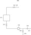
그러나, 일반적인 액처리 장치는 도 1에 도시된 바와 같이 필터의 내부 압력이 일정하게 유지되고, 이에 따라 필터 막에 의하여 여과된 오염물이 필터로부터 배출되지 못하고 누적됨에 따라 필터의 성능을 저하시켜 필터 수명이 단축되는 문제가 있다.However, in a general liquid treatment device, as shown in FIG. 1, the internal pressure of the filter is kept constant, and thus the contaminants filtered by the filter membrane are not discharged from the filter and accumulate, reducing the performance of the filter and reducing the lifespan of the filter. There is a problem with this shortening.
본 발명은 필터에 누적되는 오염 물질을 제거하여 필터의 효율을 증가시키고 필터의 수명을 증가시킬 수 있는 필터 세정 방법을 제공하고자 한다.An object of the present invention is to provide a filter cleaning method capable of increasing the efficiency of the filter and increasing the lifespan of the filter by removing contaminants accumulated on the filter.
본 발명의 목적은 여기에 제한되지 않으며, 언급되지 않은 또 다른 목적들은 아래의 기재로부터 당업자에게 명확하게 이해될 수 있을 것이다.The object of the present invention is not limited thereto, and other objects not mentioned will be clearly understood by those skilled in the art from the following description.
본 발명의 일 실시예에 의하면, 액처리 유닛에서 이용되는 처리액을 저장하는 탱크와; 상기 탱크로부터 상기 액처리 유닛을 향하는 처리액의 이동 경로를 제공하는 처리액 공급 라인과; 상기 처리액의 흐름을 형성하는 압력 펌프와; 상기 공급 라인 상에 설치되어 처리액에 포함된 파티클을 필터링하는 필터와; 상기 공급 라인 상에 배치되어 처리액을 배출시키기 위한 배출 밸브 및 배출 라인을 구비한 액처리 장치에서 상기 필터를 세정하는 필터 세정 방법이 제공될 수 있다. 상기 필터 세정 방법은, 상기 처리액의 흐름 방향을 역방향으로 전환시키는 배출 단계; 상기 역방향의 흐름 방향을 다시 정방향으로 전환시키는 처리액 공급 단계를 포함할 수 있다.According to one embodiment of the present invention, a tank for storing the treatment liquid used in the liquid treatment unit; a treatment liquid supply line providing a movement path of the treatment liquid from the tank toward the liquid treatment unit; a pressure pump to form a flow of the treatment liquid; a filter installed on the supply line to filter particles included in the treatment liquid; A filter cleaning method may be provided in which the filter is cleaned in a liquid treatment device having a discharge valve disposed on the supply line and having a discharge line for discharging the treatment liquid. The filter cleaning method may include a discharge step of changing the flow direction of the treatment liquid to a reverse direction; A treatment liquid supply step of converting the flow direction of the reverse direction back to a forward direction may be included.
상기 배출 단계는, 동작 중인 압력 펌프의 동작을 중단시키는 단계; 상기 배출 밸브를 개방하는 단계를 포함할 수 있다.The discharging step may include stopping the operation of the pressure pump in operation; opening the discharge valve.
상기 처리액 공급 단계는, 상기 배출 밸브를 폐쇄하는 단계; 상기 압력 펌프의 동작을 재개시키는 단계를 포함할 수 있다.The supplying of the treatment liquid may include closing the discharge valve; Resuming operation of the pressure pump may be included.
상기 배출 단계와 상기 처리액 공급 단계를 일정 시간씩 교대로 일정 횟수 반복 수행함으로써 상기 필터에 누적된 파티클을 제거할 수 있다.Particles accumulated in the filter may be removed by alternately performing the discharging step and the treatment solution supplying step for a predetermined time and repeatedly a predetermined number of times.
상기 압력 펌프의 동작을 중단시키면 상기 필터 내 압력이 강하되면서 처리액의 흐름이 역방향으로 전환됨에 따라 상기 필터 내 누적된 파티클이 처리액과 함께 상기 필터 외부로 배출될 수 있다.When the operation of the pressure pump is stopped, the pressure in the filter decreases and the flow of the treatment liquid is reversed, so that particles accumulated in the filter may be discharged to the outside of the filter together with the treatment liquid.
상기 필터는 멤브레인 필터(Membrane filter)를 포함할 수 있다.The filter may include a membrane filter.
한편, 상기 액처리 장치는 상기 필터에 대한 처리액의 역방향 흐름을 보조하는 보조 펌프를 더 포함할 수 있다.Meanwhile, the liquid treatment apparatus may further include an auxiliary pump assisting reverse flow of the treatment liquid to the filter.
상기 배출 단계는 상기 보조 펌프를 작동시키는 단계를 더 포함할 수 있다.The discharging step may further include operating the auxiliary pump.
본 발명의 일 실시예에 의하면, 처리액 공급 장치가 제공될 수 있다. 상기 처리액 공급 장치는, 액처리 유닛에서 이용되는 처리액을 저장하는 탱크와; 상기 탱크로부터 상기 액처리 유닛을 향하는 처리액의 이동 경로를 제공하는 처리액 공급 라인과; 상기 처리액의 공급 흐름을 형성하는 압력 펌프와; 상기 공급 라인 상에 설치되어 처리액에 포함된 파티클을 필터링하는 필터와; 상기 압력 펌프와 상기 필터 사이 구간의 공급 라인 상에 배치되어 처리액을 배출시키는 배출 밸브와; 상기 필터와 상기 액처리 유닛 사이에 설치되어 상기 처리액의 공급 흐름에 대한 역방향 흐름을 형성 가능한 보조 펌프를 포함하고, 상기 압력 펌프의 동작을 제어함으로써 상기 처리액의 흐름 방향을 반복적으로 전환시켜 상기 필터 내부의 파티클을 상기 배출 밸브를 통해 외부로 배출시킬 수 있다.According to one embodiment of the present invention, a treatment liquid supply device may be provided. The treatment liquid supply device includes a tank for storing the treatment liquid used in the liquid treatment unit; a treatment liquid supply line providing a movement path of the treatment liquid from the tank toward the liquid treatment unit; a pressure pump forming a supply flow of the treatment liquid; a filter installed on the supply line to filter particles included in the treatment liquid; a discharge valve disposed on a supply line between the pressure pump and the filter to discharge the treatment liquid; An auxiliary pump installed between the filter and the liquid processing unit and capable of forming a flow in the opposite direction to the supply flow of the treatment liquid, and controlling the operation of the pressure pump to repeatedly change the flow direction of the treatment liquid to Particles inside the filter may be discharged to the outside through the discharge valve.
본 발명의 일 실시예에 의하면, 필터 막에 누적된 오염 물질이 제거됨에 따라 필터의 효율을 증가시켜 액처리 유닛 내 파티클 발생을 방지할 수 있다.According to an embodiment of the present invention, as the contaminants accumulated on the filter membrane are removed, the efficiency of the filter may be increased, thereby preventing generation of particles in the liquid treatment unit.
또한, 본 발명의 일 실시예에 의하면, 기존의 설비 구성에 대한 변경없이 적용할 수 있는 필터 세정 방법이 제공됨으로써 필터의 수명을 증가시키고 필터의 교체 주기를 연장시켜 공정 비용을 감소시킬 수 있다.In addition, according to an embodiment of the present invention, a filter cleaning method that can be applied without changing the existing equipment configuration is provided, thereby increasing the lifespan of the filter and extending the filter replacement cycle, thereby reducing process cost.
본 발명의 효과는 상술한 효과들로 한정되는 것은 아니며, 언급되지 않은 효과들은 본 명세서 및 첨부된 도면으로부터 본 발명이 속하는 기술분야에서 통상의 지식을 가진 자에게 명확히 이해될 수 있을 것이다.The effects of the present invention are not limited to the above-mentioned effects, and effects not mentioned will be clearly understood by those skilled in the art from this specification and the accompanying drawings.
도 1은 처리액 공급 유닛에 의하여 처리액이 공급될 때의 필터 내부의 압력을 나타낸 그래프이다.
도 2는 일반적인 기판 처리 장치에 적용되는 처리액 공급 유닛의 예를 간략하게 도시한 것이다.
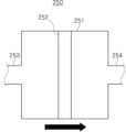
도 3은 도 2에 도시된 필터를 설명하기 위한 확대도이다.
도 4는 도 2에 도시된 처리액 공급 유닛에 의한 처리액 공급을 설명하기 위한 도면이다.
도 5는 도 4에 도시된 필터의 동작을 설명하기 위한 도면이다.
도 6는 본 발명의 실시예에 의한 필터 세정 과정을 설명하기 위한 도면이다.
도 7은 도 6의 변형예를 설명하기 위한 도면이다.
도 8은 필터 세정 과정에서의 필터 내부를 설명하기 위한 도면이다.
도 9는 본 발명의 실시예에 따른 필터 내부의 압력 변화를 도시한 그래프이다.
도 10은 본 발명의 실시예에 따른 필터 세정 방법을 설명하기 위한 흐름도이다.1 is a graph showing the pressure inside a filter when a treatment liquid is supplied by a treatment liquid supply unit.
2 schematically illustrates an example of a treatment liquid supply unit applied to a general substrate treatment apparatus.
FIG. 3 is an enlarged view for explaining the filter shown in FIG. 2 .
FIG. 4 is a diagram for explaining the supply of a treatment liquid by the treatment liquid supply unit shown in FIG. 2 .
FIG. 5 is a diagram for explaining the operation of the filter shown in FIG. 4 .
6 is a diagram for explaining a filter cleaning process according to an embodiment of the present invention.
FIG. 7 is a diagram for explaining a modified example of FIG. 6 .
8 is a view for explaining the inside of a filter in a filter cleaning process.
9 is a graph showing a change in pressure inside a filter according to an embodiment of the present invention.
10 is a flowchart for explaining a filter cleaning method according to an embodiment of the present invention.
이하, 첨부된 도면을 참조하여 본 발명의 실시예에 대하여 본 발명이 속하는 기술분야에서 통상의 지식을 가진 사람이 쉽게 실시할 수 있도록 상세히 설명한다. 그러나, 본 발명은 여러 가지 다른 형태로 구현될 수 있고 여기에서 설명하는 실시예에 한정되지 않는다.Hereinafter, with reference to the accompanying drawings, embodiments of the present invention will be described in detail so that those skilled in the art can easily carry out the present invention. However, the present invention may be embodied in many different forms and is not limited to the embodiments described herein.
본 발명의 실시예를 설명하는 데 있어서, 관련된 공지 기능이나 구성에 대한 구체적 설명이 본 발명의 요지를 불필요하게 흐릴 수 있다고 판단되는 경우에는 그 구체적 설명을 생략하고, 유사 기능 및 작용을 하는 부분은 도면 전체에 걸쳐 동일한 부호를 사용하기로 한다.In describing the embodiments of the present invention, if it is determined that a detailed description of a related known function or configuration may unnecessarily obscure the gist of the present invention, the detailed description will be omitted, and parts with similar functions and actions will be omitted. The same reference numerals will be used throughout the drawings.
명세서에서 사용되는 용어들 중 적어도 일부는 본 발명에서의 기능을 고려하여 정의한 것이기에 사용자, 운용자 의도, 관례 등에 따라 달라질 수 있다. 그러므로, 그 용어에 대해서는 명세서 전반에 걸친 내용을 토대로 하여 해석되어야 한다.Since at least some of the terms used in the specification are defined in consideration of functions in the present invention, they may vary according to user, operator intention, custom, and the like. Therefore, the term should be interpreted based on the contents throughout the specification.
또한, 명세서에서, 어떤 구성 요소를 포함한다고 하는 때, 이것은 특별히 반대되는 기재가 없는 한 다른 구성 요소를 제외하는 것이 아니라 다른 구성 요소를 더 포함할 수 있음을 의미한다. 그리고, 어떤 부분이 다른 부분과 연결(또는, 결합)된다고 하는 때, 이것은, 직접적으로 연결(또는, 결합)되는 경우뿐만 아니라, 다른 부분을 사이에 두고 간접적으로 연결(또는, 결합)되는 경우도 포함한다.In addition, in the specification, when it is said to include a certain component, this means that it may further include other components without excluding other components unless otherwise stated. And, when a part is said to be connected (or combined) with another part, this is not only directly connected (or combined), but also indirectly connected (or combined) through another part. include
한편, 도면에서 구성 요소의 크기나 형상, 선의 두께 등은 이해의 편의상 다소 과장되게 표현되어 있을 수 있다.On the other hand, in the drawing, the size or shape of the component, the thickness of the line, etc. may be expressed somewhat exaggerated for convenience of understanding.
본 발명의 실시예들은 본 발명의 이상적인 실시예들의 개략적인 도해를 참조하여 설명된다. 이에 따라, 상기 도해의 형상으로부터의 변화들, 예를 들면, 제조 방법 및/또는 허용 오차의 변화는 충분히 예상될 수 있는 것들이다. 따라서, 본 발명의 실시예들은 도해로서 설명된 영역들의 특정 형상들에 한정된 바대로 설명되어지는 것이 아니라 형상에서의 편차를 포함하는 것이며, 도면에 설명된 요소들은 전적으로 개략적인 것이며 이들의 형상은 요소들의 정확한 형상을 설명하기 위한 것이 아니며 또한 본 발명의 범위를 한정하고자 하는 것도 아니다.Embodiments of the invention are described with reference to schematic illustrations of idealized embodiments of the invention. Accordingly, variations from the shape of the illustration, eg, variations in manufacturing methods and/or tolerances, are fully to be expected. Accordingly, embodiments of the present invention are not to be described as being limited to specific shapes of regions illustrated as diagrams, but to include variations in shape, and elements described in the drawings are purely schematic and their shapes are elements. It is not intended to describe the exact shape of them, nor is it intended to limit the scope of the present invention.
상세히 도시하지는 않았지만, 본 발명에 따른 기판 처리 장치는 기판(예: 웨이퍼, 글라스 등)으로 처리액을 직접적으로 공급하여 기판을 액처리하는 액처리 유닛 및 액처리 유닛으로 처리액을 공급하는 처리액 공급 유닛(200)을 포함하여 구성되는 액처리 장치일 수 있다.Although not shown in detail, the substrate processing apparatus according to the present invention includes a liquid processing unit for liquid processing the substrate by directly supplying a processing liquid to a substrate (eg, wafer, glass, etc.) and a processing liquid for supplying the processing liquid to the liquid processing unit. It may be a liquid processing device including the
액처리 유닛은 반도체 부품 또는 디스플레이 부품에 대한 액처리 공정을 수행할 수 있다. 예를 들어, 액처리 유닛은 사진, 식각, 애싱, 식각 등의 공정을 수행할 수 있다.The liquid processing unit may perform a liquid processing process on a semiconductor component or a display component. For example, the liquid processing unit may perform processes such as photography, etching, ashing, and etching.
처리액 공급 유닛(200)은 액처리 유닛에서 이용되는 처리액을 공급할 수 있다. 액처리 유닛에서 이용되는 유체는 예를 들어, 세정액, 식각액 또는 포토레지스트액 등과 같이 액처리 유닛의 공정 처리에 이용되는 처리액일 수 있다. 또한, 액처리 유닛에서 이용되는 처리액은 액처리 유닛의 공정 처리에 이용되는 처리 가스일 수도 있다.The treatment
처리액 공급 유닛(200)과 액처리 유닛은 처리액 공급 라인(221) 및 처리액 회수 라인(222)을 통해 연결될 수 있다. 처리액 공급 라인(221)은 처리액 공급 유닛(200)으로부터 액처리 유닛을 향하는 처리액의 이동 경로를 제공하고, 처리액 회수 라인(222)은 액처리 유닛으로부터 회수된 처리액의 이동 경로를 제공할 수 있다. 즉, 처리액 공급 유닛(200)에서 액처리 유닛으로 공급된 처리액 중 일부는 액처리 유닛에서 이용되고, 나머지는 처리액 공급 유닛(200)으로 회수될 수 있다. 이때, 회수되는 처리액에 포함된 불순물을 제거하기 위한 불순물 제거 수단(미도시)이 처리액 회수 라인(222)에 구비되거나 처리액 공급 장치(200) 또는 액처리 유닛에 구비될 수 있다.The treatment
이상에서, 기판 처리 장치가 하나의 처리액 공급 유닛(200) 및 하나의 액처리 유닛을 포함하는 것을 예로 들었으나, 이는 설명의 편의를 위한 예시로서 기판 처리 장치는 하나 이상의 처리액 공급 유닛(200) 및 하나 이상의 액처리 유닛을 포함할 수 있다. 예를 들어, 하나의 처리액 공급 장치(200)가 복수의 액처리 유닛에 처리액을 공급할 수 있고, 복수의 처리액 공급 장치(200)가 하나의 액처리 유닛에 처리액을 공급할 수 있고, 복수의 처리액 공급 장치(200)가 복수의 액처리 유닛에 처리액을 공급할 수도 있는 것이다.In the above, it has been exemplified that the substrate processing apparatus includes one processing
도 2는 일반적인 처리액 공급 유닛(200)을 나타낸 도면이고, 도 3은 도 2에 도시된 필터를 나타낸 도면이다.FIG. 2 is a view showing a general treatment
도 2를 참조하면, 처리액 공급 유닛(200)은 처리액 저장 탱크(210), 처리액 공급 라인(221), 처리액 회수 라인(222), 공급 차단 밸브(231), 회수 차단 밸브(232), 압력 펌프(240), 필터(250), 배출 라인(260), 배출 밸브(262)를 포함할 수 있다.Referring to FIG. 2 , the treatment
처리액 저장 탱크(210)는 액처리 유닛으로 공급할 처리액을 저장할 수 있다.The treatment
처리액 공급 라인(221)은 처리액 저장 탱크(210)로부터 액처리 유닛을 향하는 처리액의 이동 경로를 제공하고, 처리액 회수 라인(222)은 액처리 유닛으로부터 처리액 저장 탱크(210)로 회수되는 처리액의 이동 경로를 제공할 수 있다. 처리액 회수 라인(222)을 통해 회수된 처리액은 처리액 저장 탱크(210)에 다시 저장될 수 있고, 처리액 공급 라인(221)과 처리액 회수 라인(222)은 일단이 처리액 저장 탱크(210)에 연결되고, 타단이 액처리 유닛에 연결되어 순환 라인을 형성할 수 있다.The treatment
공급 차단 밸브(231)는 처리액 공급 라인(221) 상에 설치되어 처리액 공급 라인(221)을 통한 처리액의 이동을 차단하거나 허용할 수 있다. 회수 차단 밸브(232)는 처리액 회수 라인(222) 상에 설치되어 처리액 회수 라인(222)을 통한 처리액의 이동을 차단하거나 허용할 수 있다.The
압력 펌프(240)는 처리액 공급 라인(221) 상에 배치되어 처리액을 가압하는 역할을 수행한다. 구체적으로, 압력 펌프(240)는 액처리 유닛으로 처리액을 공급하기 위한 압력을 제공할 수 있고, 이에 따라 처리액이 액처리 유닛으로 공급될 수 있다. 또한, 후술하는 바와 같이, 압력 펌프(240)를 제어함으로써 필터(250)를 세척할 수도 있다. 구체적으로, 압력 펌프(240)의 동작을 제어함에 따라 필터(250) 내부를 통과하는 처리액의 흐름이 정방향 또는 역방향으로 변경되어 필터(250) 내부에 누적된 파티클 등과 같은 오염 물질이 제거될 수 있다. 이하, 설명의 편의를 위하여, 파티클, 불순물, 오염 물질 등을 파티클로 통칭하기로 한다.The
필터(250)는 처리액 공급 라인(221) 상에 배치되어 처리액에 포함된 파티클을 필터링하는 역할을 수행한다. 필터(250)를 통과하는 처리액이 필터링 됨에 따라 액처리 유닛에는 파티클을 포함하지 않은 순수한 처리액이 공급될 수 있다. 필터(250)는 압력 펌프(240)의 후단에 배치된다. 즉, 압력 펌프(240)보다 액처리 유닛에 더 가깝게 배치된다.The
도 3을 참고하면, 필터(250)는 몸체(251), 필터 막(252), 제1 출입구(253) 및 제2 출입구(254)를 포함할 수 있다. 몸체(251)는 처리액을 수용하기 위한 공간을 제공할 수 있다. 몸체(251)에 일시적으로 수용되는 처리액은 필터 막(252)에 의하여 필터링 된 이후에 몸체(251)로부터 배출될 수 있다.Referring to FIG. 3 , the
필터 막(252)은 처리액을 여과하여 처리액 내 포함된 파티클을 필터링할 수 있다. 상세히 도시하지는 않았지만, 필터 막(252)은 복수의 미세 홀을 포함할 수 있다. 미세 홀의 직경은 처리액의 입자에 비하여 크고, 파티클에 비하여 작도록 형성될 수 있다. 처리액은 미세 홀을 통과하지만 파티클은 미세 홀을 통과하지 못하게 하기 위함이다. 또한, 필터 막(252)은 복수 개가 중첩되어 구비될 수 있다. 복수의 필터 막(252)이 중첩되어 배치됨에 따라 파티클에 대한 필터링 효율이 향상될 수 있다. 일 예로, 필터 막(252)은 멤브레인 필터(Membrane filter) 일 수 있다.The
제1 출입구(253) 및 제2 출입구(254)는 처리액 공급 라인(221)에 각각 연결될 수 있다. 제1 출입구(253) 및 제2 출입구(254)는 몸체(251)로 처리액이 유입되거나 몸체(251)로부터 처리액이 배출되는 통로 역할을 수행할 수 있다. 제1 출입구(253)를 통하여 처리액이 유입되거나 배출될 수 있고, 제2 출입구(254)를 통하여 처리액이 유입되거나 배출될 수 있다.The
다시 도 2를 참고하면, 처리액 공급 라인(221) 상에는 처리액을 외부로 배출하기 위한 배출 라인(260)이 연결될 수 있다. 배출 라인(260)은 처리액의 배출 경로를 제공할 수 있다. 구체적으로, 배출 라인(260)을 따라 배출되는 처리액은 파티클을 포함하는 처리액일 수 있다. 배출 라인(260) 상에는 배출 밸브(262)가 배치되어 처리액의 배출을 차단하거나 허용할 수 있다. 배출 라인(260)과 배출 밸브(262)는 필터(250)로부터 배출된 파티클을 포함하는 처리액을 외부로 배출시키는 역할을 수행할 수 있다.Referring back to FIG. 2 , a
필터(250)의 사용 시간이 누적됨에 따라 필터 막(252)에 파티클이 누적되어 필터(250)의 필터링 효율이 저하되거나 필터(250)의 수명이 감소될 수 있다. 본 발명의 일 실시예에 의하면, 필터(250)에 누적된 파티클이 배출 라인(260)과 배출 밸브(262)를 통해 외부로 배출될 수 있고, 이에 따라 필터(250)의 필터링 효율 및 수명이 향상될 수 있다. 자세한 설명은 후술하기로 한다.As the usage time of the
배출 라인(260)은 압력 펌프(240)와 필터(250) 사이에서 처리액 공급 라인(221)으로부터 분기되거나 연결될 수 있다. 더욱 구체적으로, 배출 라인(260)은 필터(250)의 제1 출입구(253)와 압력 펌프(240) 사이에 위치하는 처리액 공급 라인(221)으로부터 분기되거나 연결될 수 있다.The
배출 밸브(262)는 2개의 유체 출입구를 포함할 수 있다. 배출 밸브(262)는 전체 출입구를 모두 개방하여 유체가 이동하도록 하거나 전체 출입구를 차단하여 유체의 이동을 방지할 수 있다. 배출 밸브(262)에 구비된 2개의 유체 출입구 중 하나는 처리액 공급 라인(221)에 연결되고, 나머지 하나는 배출 라인(260)에 연결될 수 있다. 배출 밸브(262)는 배출 라인(260)을 통한 처리액(유체)의 배출을 허용하거나 차단할 수 있다.
도 4 및 도 5는 처리액 공급 유닛(200)이 액처리 유닛으로 처리액을 공급할 때 처리액의 흐름을 나타낸 것이다. 설명의 편의를 위하여, 이때의 처리액의 흐름을 정방향 흐름이라고 하기로 한다.4 and 5 show the flow of the treatment liquid when the treatment
도 4를 참조하면, 처리액이 처리액 공급 유닛(200)으로부터 액처리 유닛으로 공급되는 때, 압력 펌프(240)는 동작 중(ON)인 상태이고, 배출 밸브(262)는 닫혀있는(Close) 상태이다. 동작 상태의 압력 펌프(240)는 처리액 공급 라인(221)에 포함된 처리액을 가압하여 처리액이 처리액 공급 라인(221)을 통해 이동하도록 할 수 있다. 필터(250)는 처리액 공급 라인(221)을 통해 이동하는 처리액에 대한 필터링을 수행할 수 있다. 이때, 배출 밸브(262)가 닫혀있음에 따라, 배출 라인(260)을 통한 처리액의 이동은 차단되고, 처리액은 처리액 공급 라인(221)을 통한 이동만이 허용될 수 있다. 처리액은 압력 펌프(240)의 동작에 따라 제1 출입구(253)를 통해 필터(250) 내부로 유입된 후 필터 막(252)을 거쳐 제2 출입구(254)를 통해 필터(250) 외부로 배출될 수 있다.Referring to FIG. 4 , when the treatment liquid is supplied from the treatment
도 5를 참조하면, 압력 펌프(240)에 의하여 가압된 처리액은 필터부(250)를 통과할 수 있다.Referring to FIG. 5 , the treatment liquid pressurized by the
도 5(a)에 도시된 바와 같이, 처리액 탱크(210)로부터 공급된 처리액에는 파티클(PT)이 포함될 수 있다. 파티클(PT)은 처리액의 전체 영역에 분포될 수 있다. 처리액이 정방향으로 흐를 때, 제1 출입구(253)를 통해 필터(250)의 몸체(251) 내부로 유입된 처리액은, 필터 막(252)을 통과할 수 있다. 이때, 도 5(b)에 도시된 바와 같이, 처리액이 필터 막(252)을 통과하면서 처리액 내 존재하던 파티클(PT)이 처리액으로부터 분리되어 순수한 처리액만이 제2 출입구(254)를 통해 몸체(251) 외부로 배출될 수 있다. 이때, 파티클(PT)은 필터 막(252)을 통과하지 못해 몸체(251) 내부에 잔존하게 된다.As shown in FIG. 5( a ), the treatment liquid supplied from the
이와 같은 필터(250)의 필터링 동작은 처리액 공급 유닛(200)이 액처리 유닛으로 처리액을 공급하는 동안 반복적으로 수행되며, 필터(250)의 필터링 동작에는 제1 출입구(253) 쪽의 필터 막(252) 표면에 여과된 파티클이 쌓이는 현상이 수반된다. 특히나, 앞서 설명한 바와 같이, 처리액 공급 과정에서의 펌프 압력은 약 0.4Mpa 내지 0.5MPa로 필터 내부의 압력이 거의 일정하게 유지되므로, 몸체(251) 내부의 파티클들이 외부로 배출되지 못하고 몸체(251)의 내부, 구체적으로 필터 막(252) 표면에 지속적으로 누적되게 된다. 누적된 파티클에 의하면 필터 막(252)의 필터링 효율이 저하되고, 이에 따라 필터(250)를 거친 처리액에도 파티클이 존재할 수 있어 처리액 공급 라인(221)과 기판 표면에서 파티클이 발생될 가능성이 높아진다. 따라서, 기존에는 필터(250)의 효율이 감소하여 파티클 발생 횟수가 증가할 때마다 필터(250)를 새 부품으로 교체할 수밖에 없었다.The filtering operation of the
필터 교체 횟수의 증가는 공정 비용을 증가시키므로 본 발명은 필터의 수명을 늘릴 수 있는 필터 세정 방법을 제시하고자 한다.Since the increase in the number of filter replacements increases the process cost, the present invention is intended to provide a filter cleaning method capable of extending the lifespan of the filter.
도 6 내지 도 9은 필터(250)의 세정 과정을 설명하기 위한 도면이다. 도 6은 필터(250)를 세정할 때의 처리액의 흐름을 나타낸 도면이다. 본 발명의 일 실시예에 따르면, 필터(250)를 세정하기 위하여 백 플러싱(Back Flushing) 방법을 사용하여 필터(250) 내부에 누적된 파티클을 제거할 수 있다. 필터(250)의 세정 과정은 액처리 유닛 내부에 기판이 존재하지 않는 상태에서 수행되는 것이 바람직하다.6 to 9 are diagrams for explaining a cleaning process of the
도 6을 참조하면, 압력 펌프(240)의 동작이 중단(Off)되고 배출 밸브(262)가 개방(Open)된 것을 확인할 수 있다. 압력 펌프(240)의 동작을 중단시키고 배출 밸브(262)를 개방함에 따라 필터(250) 내부를 세정할 수 있다. 압력 펌프(240)의 동작을 중단시키면, 일정하게 유지되던 필터(250) 내부의 압력이 0MPa로 급격하게 떨어짐에 따라 정방향으로 흐르던 처리액이 정방향과 정 반대 방향인 역방향으로 전환된다. 즉, 처리액이 역류함에 따라, 제1 출입구(253)를 통해 필터(250) 내부로 유입됐던 처리액이 제1 출입구(253)를 통해 다시 필터 외부로 배출될 수 있다. 또한, 제2 출입구(254)를 통해 필터(250) 외부로 배출됐던 처리액이 역류하여 제2 출입구(254)를 통해 다시 필터(250) 내부로 유입될 수 있다. 이때, 처리액의 흐름이 역방향으로 전환됨에 따라, 필터 막(252)에 누적된 파티클들이 처리액과 함께 제1 출입구(253)를 통해 필터(250) 외부로 배출될 수 있다. 필터(250) 외부로 배출된 파티클과 처리액은 개방된 배출 밸브(262)를 통과하여 배출 라인(260)을 따라 외부로 배출될 수 있다. 이때, 공급 밸브(231)를 함께 폐쇄하면 처리액 저장 탱크(210)로부터의 처리액 공급이 차단되므로 처리액의 역방향 흐름이 방해되는 것을 방지할 수 있다.Referring to FIG. 6 , it can be confirmed that the operation of the
이때, 압력 펌프(240)의 전단에 별도의 밸브를 더 설치함으로써 파티클이 포함된 처리액이 압력 펌프(240)로 흐르는 것을 방지할 수 있다. 또는, 배출 밸브(262)를 3방 밸브(3 way valve)로 구비하고, 배출 라인(260)과 처리액 공급 라인(221)이 연결되는 지점에 배출 밸브(262)를 설치함으로써 파티클이 포함된 처리액이 압력 펌프(240)로 흐르는 것을 방지할 수 있다.At this time, by further installing a separate valve at the front end of the
도 7은 도 6의 변형예를 도시한 것이다.FIG. 7 shows a modified example of FIG. 6 .
도 7에 도시된 바와 같이, 필터(250)의 세정 효과를 극대화하기 위하여 처리액 공급 라인(221) 상에 별도의 보조 펌프(270)를 더 설치할 수 있다. 보조 펌프(270)는 필터(250)와 액처리 유닛의 사이 구간에 설치되어 처리액의 역방향 이동을 위한 압력을 제공할 수 있다. 보조 펌프(270)는 필터(250) 세정 과정에서, 특히 처리액의 역방향 흐름을 보조하기 위해서만 동작(On)하도록 제공될 수 있다. 따라서 처리액이 정방향으로 흐르는 과정에서는 동작이 중단(Off)되어 처리액의 공급 흐름에 전혀 영향을 주지 않도록 제공될 수 있다.As shown in FIG. 7 , a separate
도 8은 필터(250) 세정 과정에서 필터(250) 내부의 파티클이 제거되는 과정을 설명하기 위한 도면이다.FIG. 8 is a diagram for explaining a process of removing particles inside the
도 8(a)에 도시된 바와 같이, 정방향으로 흐르던 처리액은, 압력 펌프(240)의 작동이 중단됨에 따라 도 7(b)와 같이 역방향으로 흐르게 된다. 처리액이 역방향으로 흐르게 됨에 따라, 필터 막(252)의 표면에 누적되어 있던 파티클들이 처리액과 함께 제1 출입구(253)로 배출될 수 있다. 이때, 처리액의 역방향 흐름은 보조 펌프에 의하여 보조될 수 있다.As shown in FIG. 8(a), the treatment liquid flowing in the forward direction flows in the reverse direction as shown in FIG. 7(b) as the operation of the
필터(250) 내부에 누적된 파티클들을 확실하게 제거하기 위해, 처리액의 정방향 흐름과 역방향 흐름을 일정 시간씩 반복 수행시킬 수 있다. 예를 들어, 도 8(a)를 1분 동안 유지한 후 압력 펌프(240)의 작동을 멈추고 배출 밸브(262)를 개방하여 도 8(b)를 1분 동안 유지하는 하나의 사이클을 일정 횟수만큼 반복한다면, 필터(250) 내부에 누적된 파티클들이 모두 제거될 수 있을 것이다. 일 예로, 일정 횟수는 15회일 수 있다. 전술한 바와 같이, 필터 세정 과정에 의하여 액 처리 유닛으로 파티클이 제공될 가능성이 있으므로 액 처리 유닛 내부에 기판이 존재하지 않은 상태에서 수행되는 것이 바람직하다. 또는, 상세히 도시되지 않았지만, 처리액 공급 라인(221) 상에 필터(250)를 통과한 처리액이 압력 펌프(240)로 다시 제공될 수 있도록 순환 경로를 제공하는 보조 라인을 더 형성하여 액 처리 유닛으로 파티클이 유입되는 것을 방지할 수도 있다.In order to reliably remove particles accumulated inside the
도 9는 앞서 설명한 과정을 반복 수행했을 때 시간에 따른 필터(250)의 압력 변화를 도시한 것이다. 도 9에 도시된 바와 같이, 필터(250) 내부의 압력이 0.4 MPa와 0 MPa으로 펄스 형태처럼 반복됨에 따라, 필터(250)를 통과하는 처리액의 흐름 방향이 정방향 또는 역방향으로 반복적으로 전환되면서 필터(250) 내부에 누적된 파티클(PT)이 필터(250) 외부로 배출될 수 있다. 필터(250) 외부로 배출된 파티클(PT)은 배출 밸브(262)를 통해 배출 라인(260)을 따라 장치 외부로 배출될 수 있다.9 illustrates a change in pressure of the
도 10은 본 발명의 실시예에 따른 필터 세정 방법을 설명하기 위한 흐름도이다.10 is a flowchart for explaining a filter cleaning method according to an embodiment of the present invention.
도 10을 참조하면, 본 발명의 실시예에 따른 필터 세정 방법은, 처리액의 흐름을 역방향으로 전환시키는 배출 단계(S10)와 역방향으로 전환된 처리액의 흐름을 다시 정방향으로 전환시키는 처리액 공급 단계(S20)를 포함할 수 있다.Referring to FIG. 10 , in the filter cleaning method according to an embodiment of the present invention, the discharge step (S10) of converting the flow of the treatment liquid in the reverse direction and the supply of the treatment liquid for converting the reverse flow of the treatment liquid back into the forward direction. Step (S20) may be included.
배출 단계(S10)는, 동작 중이던 압력 펌프(240)의 동작을 중단시킴으로써 처리액의 흐름을 역방향으로 전환시켜 필터(250)에 누적된 파티클을 외부로 배출할 수 있다.In the discharging step ( S10 ), by stopping the operation of the
구체적으로, 배출 단계(S10)는 동작 중인 압력 펌프(240)의 동작을 중단(OFF)시키는 단계(S11), 배출 밸브(262)를 개방(OPEN)하는 단계(S12)를 포함할 수 있다. 동작 중이던 압력 펌프(240)의 동작을 중단시키면, 압력 펌프(240)에 의하여 일정 압력으로 유지되던 필터(250)의 압력이 급격하게 0으로 떨어지면서 처리액의 흐름 방향이 역방향으로 전환될 수 있다. 따라서, 액처리 유닛으로 처리액을 공급하기 위하여 정방향으로 필터(250)를 통과하던 처리액의 흐름이 역방향으로 전환됨에 따라, 필터 막(252)에 누적된 파티클이 역방향으로 흐르는 처리액과 함께 필터(250) 외부로 배출될 수 있다. 필터(250) 외부로 배출된 파티클을 포함하는 처리액은 개방된 배출 밸브(262)로 흘러 배출 라인(260)을 따라 처리액 공급 유닛(200)의 외부로 배출될 수 있다.Specifically, the discharging step (S10) may include stopping (OFF) the operation of the
이때, 배출 단계(S10)는 공급 밸브(231)를 폐쇄(Close)하는 단계와 보조 펌프를 동작(On) 시키는 단계를 더 포함할 수 있다.At this time, the discharge step (S10) may further include the step of closing (Close) the
처리액 공급 단계(S20)는 개방된 배출 밸브(262)를 폐쇄(Close)하는 단계(S21), 압력 펌프(240)의 동작을 재개(On)시키는 단계(S22)를 포함할 수 있다. 처리액 공급 단계(S20)는 압력 펌프(240)의 동작을 재개(On)시킴으로써 역방향으로 흐르는 처리액의 흐름을 다시 정방향으로 전환시킬 수 있다.The treatment liquid supplying step ( S20 ) may include closing the discharge valve 262 ( S21 ) and restarting ( On ) the operation of the pressure pump 240 ( S22 ). In the supplying of the treatment liquid ( S20 ), the flow of the treatment liquid flowing in the reverse direction may be switched back to the forward direction by resuming (On) the operation of the
배출 단계(S10)와 처리액 공급 단계(S20)는 각각 일정 시간 동안 수행되고, 일정 횟수(N)만큼 수행될 때까지 반복될 수 있다.Each of the discharging step (S10) and the treatment liquid supplying step (S20) may be performed for a predetermined time, and may be repeated until they are performed a predetermined number of times (N).
배출 단계(S10)와 처리액 공급 단계(S20)를 일정 시간씩 번갈아가며 반복 수행할 경우, 백 플러싱(Back Flushing)효과가 발생할 수 있다. 본 발명의 실시예에 따른 필터 세정 방법은, 이러한 백 플러싱 효과를 기존의 처리액 공급 장치에 적용함으로써 필터 내부에 누적된 파티클을 제거할 수 있다.When the discharge step (S10) and the treatment liquid supply step (S20) are alternately and repeatedly performed for a predetermined time, a back flushing effect may occur. In the filter cleaning method according to the embodiment of the present invention, particles accumulated inside the filter may be removed by applying the bag flushing effect to the existing treatment liquid supply device.
백 플러싱 효과란, 필터(250) 내부의 압력을 급격하게 하락시킴으로써 필터(250)를 통과하는 처리액의 흐름 방향을 역방향으로 전환시켜 필터 막(252)에 잔존하는 파티클을 외부로 배출하는 배출 단계(S10)와 처리액의 정방향 흐름을 형성하는 처리액 공급 단계(S20)를 복수 회 반복함으로써 필터(250)에 누적된 파티클을 제거하는 것과 같이 유체의 정순환과 역순환의 반복을 이용한 세정 효과를 뜻한다.The back flushing effect is a discharge step of discharging particles remaining on the
배출 단계(S10)와 처리액 공급 단계(S20)가 유지되는 일정 시간은 작업자에 의하여 설정될 수 있고, 수행 횟수 역시 작업자에 의하여 설정될 수 있다. 일 예로, 배출 단계(S10)와 처리액 공급 단계(S20)는 1분씩 번갈아가며 15회 수행될 수 있다. 또는, 배출 단계(S10)와 처리액 공급 단계(S20)는 필터(250) 내 잔존하는 파티클이 모두 제거될 때까지 교대로 반복될 수도 있다.A certain amount of time during which the discharging step (S10) and the treatment liquid supplying step (S20) are maintained may be set by the operator, and the number of executions may also be set by the operator. For example, the discharging step (S10) and the treatment liquid supplying step (S20) may be alternately performed 15 times for 1 minute each. Alternatively, the discharging step ( S10 ) and the treatment liquid supplying step ( S20 ) may be alternately repeated until all remaining particles in the
필터(250)에 누적되어 존재하던 파티클이 필터 세정 방법에 의하여 제거되면, 필터의 효율을 최대한 유지할 수 있고 이에 따라 필터의 수명을 연장시킬 수 있다. 또한, 필터의 효율 저하로 인한 파티클의 누출을 방지할 수 있다. 상술한 방법은 기존의 설비의 제어 방법을 변경함으로써 필터를 세척할 수 있는 방법이므로 다양한 기존의 설비에 적용될 수 있고, 필터뿐만 아니라 밸브, 배관 등 유체의 흐름이 적용되는 다양한 부품의 세척에 적용될 수 있을 것이다.If the particles accumulated in the
이상에서는 본 발명을 설명하였으나, 본 발명은 개시된 실시예 및 첨부된 도면에 의하여 한정되지 않으며 본 발명의 기술적 사상을 벗어나지 않는 범위 이내에서 통상의 기술자에 의하여 다양하게 변형될 수 있다. 또한, 본 발명의 실시예에서 설명한 기술적 사상은 각각 독립적으로 실시될 수도 있고 둘 이상이 서로 조합되어 실시될 수도 있다.Although the present invention has been described above, the present invention is not limited by the disclosed embodiments and the accompanying drawings, and may be variously modified by a person skilled in the art without departing from the technical spirit of the present invention. In addition, the technical ideas described in the embodiments of the present invention may be implemented independently or two or more may be combined with each other.
200: 처리액 공급 장치
210: 처리액 저장 탱크
221: 처리액 공급 라인
222: 처리액 회수 라인
231: 공급 차단 밸브
232: 회수 차단 밸브
240: 압력 펌프
250: 필터
251: 몸체
252: 필터 막
253, 254: 출입구
260: 배출 라인
262: 배출 밸브
270: 보조 펌프200: treatment liquid supply device
210: treatment liquid storage tank
221: treatment liquid supply line
222: treatment liquid recovery line
231: supply shutoff valve
232: return shutoff valve
240: pressure pump
250: filter
251: body
252 filter membrane
253, 254: entrance
260: discharge line
262: discharge valve
270: auxiliary pump
Claims (9)
Translated fromKorean상기 처리액의 흐름 방향을 역방향으로 전환시키는 배출 단계;
상기 역방향의 흐름 방향을 다시 정방향으로 전환시키는 처리액 공급 단계;
를 포함하는 필터 세정 방법.
a tank for storing the treatment liquid used in the liquid treatment unit; a treatment liquid supply line providing a movement path of the treatment liquid from the tank toward the liquid treatment unit; a pressure pump to form a flow of the treatment liquid; a filter installed on the supply line to filter particles included in the treatment liquid; In the filter cleaning method of cleaning the filter in a liquid treatment device disposed on the supply line and having a discharge valve and a discharge line for discharging the treatment liquid,
a discharge step of changing the flow direction of the treatment liquid to a reverse direction;
a treatment liquid supplying step of converting the flow direction of the reverse direction back to a forward direction;
Filter cleaning method comprising a.
상기 배출 단계는,
동작 중인 압력 펌프의 동작을 중단시키는 단계;
상기 배출 밸브를 개방하는 단계;
를 포함하는 것을 특징으로 하는 필터 세정 방법.
According to claim 1,
In the discharge step,
stopping the operation of the pressure pump in operation;
opening the discharge valve;
Filter cleaning method comprising a.
상기 처리액 공급 단계는,
상기 배출 밸브를 폐쇄하는 단계;
상기 압력 펌프의 동작을 재개시키는 단계;
를 포함하는 것을 특징으로 하는 필터 세정 방법.
According to claim 2,
In the step of supplying the treatment solution,
closing the discharge valve;
resuming operation of the pressure pump;
Filter cleaning method comprising a.
상기 배출 단계와 상기 처리액 공급 단계를 일정 시간씩 교대로 일정 횟수만큼 반복 수행함으로써 상기 필터에 누적된 파티클을 제거하는 것을 특징으로 하는 필터 세정 방법.
According to any one of claims 1 to 3,
The filter cleaning method, characterized in that by repeating the discharge step and the treatment liquid supply step alternately for a predetermined time a predetermined number of times to remove the particles accumulated in the filter.
상기 압력 펌프의 동작을 중단시키면 상기 필터 내 압력이 강하되면서 처리액의 흐름이 역방향으로 전환됨에 따라 상기 필터 내 누적된 파티클이 처리액과 함께 상기 필터 외부로 배출되는 것을 특징으로 하는 필터 세정 방법.
According to claim 2,
When the operation of the pressure pump is stopped, the pressure in the filter decreases and the flow of the treatment liquid is reversed, so that particles accumulated in the filter are discharged to the outside of the filter together with the treatment liquid.
상기 필터는 멤브레인 필터(Membrane filter)를 포함하는 필터 세정 방법.
According to claim 1,
The filter cleaning method comprising a membrane filter.
상기 액처리 장치는 상기 필터에 대한 처리액의 역방향 흐름을 보조하는 보조 펌프를 더 포함하는 필터 세정 방법.
According to claim 1,
The liquid treatment device further comprises an auxiliary pump assisting reverse flow of the treatment liquid to the filter.
상기 배출 단계는 상기 보조 펌프를 작동시키는 단계를 더 포함하는 필터 세정 방법.
According to claim 7,
The filter cleaning method of claim 1, wherein the discharging step further comprises operating the auxiliary pump.
액처리 유닛에서 이용되는 처리액을 저장하는 탱크와;
상기 탱크로부터 상기 액처리 유닛을 향하는 처리액의 이동 경로를 제공하는 처리액 공급 라인과;
상기 처리액의 공급 흐름을 형성하는 압력 펌프와;
상기 공급 라인 상에 설치되어 처리액에 포함된 파티클을 필터링하는 필터와;
상기 압력 펌프와 상기 필터 사이 구간의 공급 라인 상에 배치되어 처리액을 배출시키는 배출 밸브와;
상기 필터와 상기 액처리 유닛 사이에 설치되어 상기 처리액의 공급 흐름에 대한 역방향 흐름을 형성 가능한 보조 펌프를 포함하고,
상기 압력 펌프의 동작을 제어함으로써 상기 처리액의 흐름 방향을 반복적으로 전환시켜 상기 필터 내부의 파티클을 상기 배출 밸브를 통해 외부로 배출시키는 처리액 공급 장치.As a treatment liquid supply device,
a tank for storing the treatment liquid used in the liquid treatment unit;
a treatment liquid supply line providing a movement path of the treatment liquid from the tank toward the liquid treatment unit;
a pressure pump forming a supply flow of the treatment liquid;
a filter installed on the supply line to filter particles included in the treatment liquid;
a discharge valve disposed on a supply line between the pressure pump and the filter to discharge the treatment liquid;
An auxiliary pump installed between the filter and the liquid processing unit to form a reverse flow with respect to the supply flow of the treatment liquid;
A treatment liquid supply device configured to repeatedly change a flow direction of the treatment liquid by controlling an operation of the pressure pump to discharge particles inside the filter to the outside through the discharge valve.
Priority Applications (1)
| Application Number | Priority Date | Filing Date | Title |
|---|---|---|---|
| KR1020210111957AKR20230030129A (en) | 2021-08-24 | 2021-08-24 | The method of cleaning filter |
Applications Claiming Priority (1)
| Application Number | Priority Date | Filing Date | Title |
|---|---|---|---|
| KR1020210111957AKR20230030129A (en) | 2021-08-24 | 2021-08-24 | The method of cleaning filter |
Publications (1)
| Publication Number | Publication Date |
|---|---|
| KR20230030129Atrue KR20230030129A (en) | 2023-03-06 |
Family
ID=85509565
Family Applications (1)
| Application Number | Title | Priority Date | Filing Date |
|---|---|---|---|
| KR1020210111957APendingKR20230030129A (en) | 2021-08-24 | 2021-08-24 | The method of cleaning filter |
Country Status (1)
| Country | Link |
|---|---|
| KR (1) | KR20230030129A (en) |
Citations (1)
| Publication number | Priority date | Publication date | Assignee | Title |
|---|---|---|---|---|
| KR20150138928A (en) | 2014-05-30 | 2015-12-11 | 세메스 주식회사 | filter unit and having the same Apparatus for supplying chemical |
- 2021
- 2021-08-24KRKR1020210111957Apatent/KR20230030129A/enactivePending
Patent Citations (1)
| Publication number | Priority date | Publication date | Assignee | Title |
|---|---|---|---|---|
| KR20150138928A (en) | 2014-05-30 | 2015-12-11 | 세메스 주식회사 | filter unit and having the same Apparatus for supplying chemical |
Similar Documents
| Publication | Publication Date | Title |
|---|---|---|
| KR102411805B1 (en) | Processing liquid supplying apparatus and method for cleaning the same | |
| JP2007234862A (en) | Apparatus and method for high pressure process | |
| TW201529142A (en) | Processing liquid supplying apparatus and processing liquid supplying method | |
| JP2017191821A (en) | Filter raising device, treating liquid supplying device, fixture unit, and method of rising filter | |
| KR102254187B1 (en) | Substrate drying apparatus | |
| KR102314052B1 (en) | Filter cleaning method, liquid processing apparatus and storage medium | |
| WO2019182036A1 (en) | Liquid processing device and liquid processing method | |
| JP6278808B2 (en) | Liquid supply device and filter cleaning method | |
| JP2015177090A (en) | Treatment liquid supply device | |
| CN111788660A (en) | Processing liquid supply apparatus, substrate processing apparatus, and processing liquid supply method | |
| KR102113433B1 (en) | Repairing Apparatus for Inkjet Printer | |
| KR20230030129A (en) | The method of cleaning filter | |
| CN101730577B (en) | How the water purifier works | |
| JP6576770B2 (en) | Filter replacement method in substrate processing apparatus | |
| KR102275713B1 (en) | Apparatus for providing fluid | |
| US12350609B2 (en) | Pre-wet system having pneumatic circulation | |
| JP4620599B2 (en) | Foreign matter removal processing device | |
| US12427451B2 (en) | Vacuum assisted filtration | |
| KR102298895B1 (en) | Gas exhausting equipment operating method for cleaning exhaust pipe of semiconductor production facility | |
| KR20200139852A (en) | Substrate drying chamber | |
| KR102680710B1 (en) | Substrate cleaning apparatus | |
| JP2008053386A (en) | Substrate processing apparatus and substrate processing method | |
| US20240105469A1 (en) | Liquid supply system | |
| TWI896599B (en) | Vacuum assisted filtration | |
| KR100636618B1 (en) | Filter Purification System for Large Area Substrate Processing System |
Legal Events
| Date | Code | Title | Description |
|---|---|---|---|
| PA0109 | Patent application | St.27 status event code:A-0-1-A10-A12-nap-PA0109 | |
| PN2301 | Change of applicant | St.27 status event code:A-3-3-R10-R13-asn-PN2301 St.27 status event code:A-3-3-R10-R11-asn-PN2301 | |
| R18-X000 | Changes to party contact information recorded | St.27 status event code:A-3-3-R10-R18-oth-X000 | |
| PG1501 | Laying open of application | St.27 status event code:A-1-1-Q10-Q12-nap-PG1501 | |
| A201 | Request for examination | ||
| PA0201 | Request for examination | St.27 status event code:A-1-2-D10-D11-exm-PA0201 | |
| PN2301 | Change of applicant | St.27 status event code:A-3-3-R10-R13-asn-PN2301 St.27 status event code:A-3-3-R10-R11-asn-PN2301 | |
| D13-X000 | Search requested | St.27 status event code:A-1-2-D10-D13-srh-X000 |