KR20230023153A - Painless syringe to reduce the noise and friction generated when perforating the alveolar bone - Google Patents
Painless syringe to reduce the noise and friction generated when perforating the alveolar boneDownload PDFInfo
- Publication number
- KR20230023153A KR20230023153AKR1020210104995AKR20210104995AKR20230023153AKR 20230023153 AKR20230023153 AKR 20230023153AKR 1020210104995 AKR1020210104995 AKR 1020210104995AKR 20210104995 AKR20210104995 AKR 20210104995AKR 20230023153 AKR20230023153 AKR 20230023153A
- Authority
- KR
- South Korea
- Prior art keywords
- holder
- alveolar bone
- noise
- reduce
- housing
- Prior art date
- Legal status (The legal status is an assumption and is not a legal conclusion. Google has not performed a legal analysis and makes no representation as to the accuracy of the status listed.)
- Abandoned
Links
Images


Classifications
- A—HUMAN NECESSITIES
- A61—MEDICAL OR VETERINARY SCIENCE; HYGIENE
- A61C—DENTISTRY; APPARATUS OR METHODS FOR ORAL OR DENTAL HYGIENE
- A61C1/00—Dental machines for boring or cutting ; General features of dental machines or apparatus, e.g. hand-piece design
- A61C1/08—Machine parts specially adapted for dentistry
- A61C1/087—Supplying powder or medicines
- A—HUMAN NECESSITIES
- A61—MEDICAL OR VETERINARY SCIENCE; HYGIENE
- A61C—DENTISTRY; APPARATUS OR METHODS FOR ORAL OR DENTAL HYGIENE
- A61C5/00—Filling or capping teeth
- A61C5/40—Implements for surgical treatment of the roots or nerves of the teeth; Nerve needles; Methods or instruments for medication of the roots
- A—HUMAN NECESSITIES
- A61—MEDICAL OR VETERINARY SCIENCE; HYGIENE
- A61C—DENTISTRY; APPARATUS OR METHODS FOR ORAL OR DENTAL HYGIENE
- A61C1/00—Dental machines for boring or cutting ; General features of dental machines or apparatus, e.g. hand-piece design
- A61C1/08—Machine parts specially adapted for dentistry
- A61C1/081—Pain-alleviating features
- A—HUMAN NECESSITIES
- A61—MEDICAL OR VETERINARY SCIENCE; HYGIENE
- A61C—DENTISTRY; APPARATUS OR METHODS FOR ORAL OR DENTAL HYGIENE
- A61C1/00—Dental machines for boring or cutting ; General features of dental machines or apparatus, e.g. hand-piece design
- A61C1/08—Machine parts specially adapted for dentistry
- A61C1/10—Straight hand-pieces
- A—HUMAN NECESSITIES
- A61—MEDICAL OR VETERINARY SCIENCE; HYGIENE
- A61C—DENTISTRY; APPARATUS OR METHODS FOR ORAL OR DENTAL HYGIENE
- A61C19/00—Dental auxiliary appliances
- A61C19/06—Implements for therapeutic treatment
- A61C19/08—Implements for therapeutic treatment combined with anaesthetising implements
- A—HUMAN NECESSITIES
- A61—MEDICAL OR VETERINARY SCIENCE; HYGIENE
- A61C—DENTISTRY; APPARATUS OR METHODS FOR ORAL OR DENTAL HYGIENE
- A61C5/00—Filling or capping teeth
- A61C5/50—Implements for filling root canals; Methods or instruments for medication of tooth nerve channels
- A—HUMAN NECESSITIES
- A61—MEDICAL OR VETERINARY SCIENCE; HYGIENE
- A61J—CONTAINERS SPECIALLY ADAPTED FOR MEDICAL OR PHARMACEUTICAL PURPOSES; DEVICES OR METHODS SPECIALLY ADAPTED FOR BRINGING PHARMACEUTICAL PRODUCTS INTO PARTICULAR PHYSICAL OR ADMINISTERING FORMS; DEVICES FOR ADMINISTERING FOOD OR MEDICINES ORALLY; BABY COMFORTERS; DEVICES FOR RECEIVING SPITTLE
- A61J1/00—Containers specially adapted for medical or pharmaceutical purposes
- A61J1/05—Containers specially adapted for medical or pharmaceutical purposes for collecting, storing or administering blood, plasma or medical fluids ; Infusion or perfusion containers
- A61J1/06—Ampoules or carpules
- A—HUMAN NECESSITIES
- A61—MEDICAL OR VETERINARY SCIENCE; HYGIENE
- A61J—CONTAINERS SPECIALLY ADAPTED FOR MEDICAL OR PHARMACEUTICAL PURPOSES; DEVICES OR METHODS SPECIALLY ADAPTED FOR BRINGING PHARMACEUTICAL PRODUCTS INTO PARTICULAR PHYSICAL OR ADMINISTERING FORMS; DEVICES FOR ADMINISTERING FOOD OR MEDICINES ORALLY; BABY COMFORTERS; DEVICES FOR RECEIVING SPITTLE
- A61J1/00—Containers specially adapted for medical or pharmaceutical purposes
- A61J1/14—Details; Accessories therefor
- A61J1/20—Arrangements for transferring or mixing fluids, e.g. from vial to syringe
- A61J1/2096—Combination of a vial and a syringe for transferring or mixing their contents
- A—HUMAN NECESSITIES
- A61—MEDICAL OR VETERINARY SCIENCE; HYGIENE
- A61M—DEVICES FOR INTRODUCING MEDIA INTO, OR ONTO, THE BODY; DEVICES FOR TRANSDUCING BODY MEDIA OR FOR TAKING MEDIA FROM THE BODY; DEVICES FOR PRODUCING OR ENDING SLEEP OR STUPOR
- A61M5/00—Devices for bringing media into the body in a subcutaneous, intra-vascular or intramuscular way; Accessories therefor, e.g. filling or cleaning devices, arm-rests
- A61M5/178—Syringes
- A61M5/24—Ampoule syringes, i.e. syringes with needle for use in combination with replaceable ampoules or carpules, e.g. automatic
- A61M5/2422—Ampoule syringes, i.e. syringes with needle for use in combination with replaceable ampoules or carpules, e.g. automatic using emptying means to expel or eject media, e.g. pistons, deformation of the ampoule, or telescoping of the ampoule
- A61M5/2425—Ampoule syringes, i.e. syringes with needle for use in combination with replaceable ampoules or carpules, e.g. automatic using emptying means to expel or eject media, e.g. pistons, deformation of the ampoule, or telescoping of the ampoule by compression of deformable ampoule or carpule wall
- A—HUMAN NECESSITIES
- A61—MEDICAL OR VETERINARY SCIENCE; HYGIENE
- A61M—DEVICES FOR INTRODUCING MEDIA INTO, OR ONTO, THE BODY; DEVICES FOR TRANSDUCING BODY MEDIA OR FOR TAKING MEDIA FROM THE BODY; DEVICES FOR PRODUCING OR ENDING SLEEP OR STUPOR
- A61M5/00—Devices for bringing media into the body in a subcutaneous, intra-vascular or intramuscular way; Accessories therefor, e.g. filling or cleaning devices, arm-rests
- A61M5/178—Syringes
- A61M5/24—Ampoule syringes, i.e. syringes with needle for use in combination with replaceable ampoules or carpules, e.g. automatic
- A61M2005/2403—Ampoule inserted into the ampoule holder
- A61M2005/2407—Ampoule inserted into the ampoule holder from the rear
- A—HUMAN NECESSITIES
- A61—MEDICAL OR VETERINARY SCIENCE; HYGIENE
- A61M—DEVICES FOR INTRODUCING MEDIA INTO, OR ONTO, THE BODY; DEVICES FOR TRANSDUCING BODY MEDIA OR FOR TAKING MEDIA FROM THE BODY; DEVICES FOR PRODUCING OR ENDING SLEEP OR STUPOR
- A61M5/00—Devices for bringing media into the body in a subcutaneous, intra-vascular or intramuscular way; Accessories therefor, e.g. filling or cleaning devices, arm-rests
- A61M5/178—Syringes
- A61M5/24—Ampoule syringes, i.e. syringes with needle for use in combination with replaceable ampoules or carpules, e.g. automatic
- A61M2005/2485—Ampoule holder connected to rest of syringe
- A—HUMAN NECESSITIES
- A61—MEDICAL OR VETERINARY SCIENCE; HYGIENE
- A61M—DEVICES FOR INTRODUCING MEDIA INTO, OR ONTO, THE BODY; DEVICES FOR TRANSDUCING BODY MEDIA OR FOR TAKING MEDIA FROM THE BODY; DEVICES FOR PRODUCING OR ENDING SLEEP OR STUPOR
- A61M2202/00—Special media to be introduced, removed or treated
- A61M2202/04—Liquids
- A61M2202/0468—Liquids non-physiological
- A61M2202/048—Anaesthetics
- A—HUMAN NECESSITIES
- A61—MEDICAL OR VETERINARY SCIENCE; HYGIENE
- A61M—DEVICES FOR INTRODUCING MEDIA INTO, OR ONTO, THE BODY; DEVICES FOR TRANSDUCING BODY MEDIA OR FOR TAKING MEDIA FROM THE BODY; DEVICES FOR PRODUCING OR ENDING SLEEP OR STUPOR
- A61M2205/00—General characteristics of the apparatus
- A61M2205/02—General characteristics of the apparatus characterised by a particular materials
- A61M2205/0222—Materials for reducing friction
- A—HUMAN NECESSITIES
- A61—MEDICAL OR VETERINARY SCIENCE; HYGIENE
- A61M—DEVICES FOR INTRODUCING MEDIA INTO, OR ONTO, THE BODY; DEVICES FOR TRANSDUCING BODY MEDIA OR FOR TAKING MEDIA FROM THE BODY; DEVICES FOR PRODUCING OR ENDING SLEEP OR STUPOR
- A61M2205/00—General characteristics of the apparatus
- A61M2205/42—Reducing noise
- A—HUMAN NECESSITIES
- A61—MEDICAL OR VETERINARY SCIENCE; HYGIENE
- A61M—DEVICES FOR INTRODUCING MEDIA INTO, OR ONTO, THE BODY; DEVICES FOR TRANSDUCING BODY MEDIA OR FOR TAKING MEDIA FROM THE BODY; DEVICES FOR PRODUCING OR ENDING SLEEP OR STUPOR
- A61M2210/00—Anatomical parts of the body
- A61M2210/02—Bones
Landscapes
- Health & Medical Sciences (AREA)
- Life Sciences & Earth Sciences (AREA)
- Animal Behavior & Ethology (AREA)
- General Health & Medical Sciences (AREA)
- Public Health (AREA)
- Veterinary Medicine (AREA)
- Oral & Maxillofacial Surgery (AREA)
- Engineering & Computer Science (AREA)
- Epidemiology (AREA)
- Dentistry (AREA)
- Anesthesiology (AREA)
- Biomedical Technology (AREA)
- Hematology (AREA)
- Vascular Medicine (AREA)
- Heart & Thoracic Surgery (AREA)
- Pharmacology & Pharmacy (AREA)
- Pain & Pain Management (AREA)
- Medical Informatics (AREA)
- Neurology (AREA)
- Neurosurgery (AREA)
- Nuclear Medicine, Radiotherapy & Molecular Imaging (AREA)
- Surgery (AREA)
- Infusion, Injection, And Reservoir Apparatuses (AREA)
Abstract
Translated fromKoreanDescription
Translated fromKorean본 발명은 치조골을 천공할 때 발생되는 소음 및 마찰력을 감소시키기 위한 무통주사기에 관한 것으로서, 더욱 상세하게는 치과 치료를 위해 마취액을 주사할 때 바늘을 회전시켜 치조골을 천공할 때 회전 부위의 마찰에 의해 회전력이 감소되지 않도록 하기 위한 치조골을 천공할 때 발생되는 소음 및 마찰력을 감소시키기 위한 무통주사기에 관한 것이다.The present invention relates to a painless syringe for reducing noise and friction generated when perforating the alveolar bone, and more particularly, when injecting an anesthetic for dental treatment by rotating a needle to perforate the alveolar bone, the friction of the rotation part It relates to a painless syringe for reducing noise and frictional force generated when perforating the alveolar bone so that the rotational force is not reduced by the.
일반적으로 국소마취는 마취액을 수술할 부위에 직접 주입하여 수술 부위만을 마취하는 것을 의미하며, 치과에서 임플란트 등을 시술 할 경우에 주로 사용되고 있다.In general, local anesthesia means to anesthetize only the surgical area by directly injecting an anesthetic liquid into the area to be operated, and is mainly used when implants are operated in dentistry.
종래의 경우 시술자가 직접 주사기에 마취액을 충진시킨 후에 마취액을 주사하게 되는데, 마취액의 주입 속도를 높이게 되면 환부에 과도한 압력이 생성되어 환자가 고통을 느끼게 된다.In the prior art, the operator directly fills the syringe with the anesthetic solution and then injects the anesthetic solution. When the injection speed of the anesthetic solution is increased, excessive pressure is generated in the affected area, causing the patient to feel pain.
즉, 마취액을 주입하는 압력 및 속도는 국소 마취 시 통증을 유발시킬 수 있는 가장 큰 요인이라 할 수 있으며, 시술자가 주입하는 속도 및 압력은 일정하지 않고 주입되는 상태를 수치적으로 확인할 수 없어 환자가 주입시 발생하는 고통을 참아야 하는 문제점이 있었다.In other words, the pressure and speed of injecting the anesthetic solution are the biggest factors that can cause pain during local anesthesia. There was a problem of having to endure the pain that occurs during injection.
이러한 문제점을 해결하기 위한 한국특허 공개번호 제10-2019-0101062호는 정확한 위치의 환부에 약물을 주입함에 있어 주입량, 주입속도를 결정하여 통증을 최소화하는 것이 가능한 무통 마취 주사장치에 관한 것으로서, 일측이 하우징의 연결부에 연결되고, 타측이 니들부에 결합되어 내부에 약물을 수용하는 앰풀부와, 하우징 내부에 배치되고 앰풀부에 압력을 가하여 약물을 니들부를 통해 주입하도록 하는 플런저와, 플런저를 이송시키는 모터 및 주입 모드에 따라 모터에 구동 제어 신호를 전송하는 제어부를 포함하여 구성되어 있다.Korean Patent Publication No. 10-2019-0101062 to solve this problem relates to a painless anesthetic injection device capable of minimizing pain by determining the injection amount and injection speed when injecting drugs into an affected area in an accurate position. An ampoule connected to the connection part of the housing and the other side coupled to the needle part to accommodate the drug therein, a plunger disposed inside the housing and applying pressure to the ampoule part to inject the drug through the needle part, and transporting the plunger It is configured to include a controller that transmits a driving control signal to the motor according to the motor and the injection mode.
상기와 같은 종래기술을 이용하면 주입속도가 일정하고 주입량을 제어할 수 있어 환자가 받는 고통을 경감시킬 수 있으나, 임플란트와 같은 시술을 위해 치조골 내부에 마취액을 주사하기 위해서는 여전히 주사 위치까지 시술자가 수동으로 바늘을 찔러 넣어야 하는 문제점이 있었다.When using the prior art as described above, the injection speed is constant and the injection amount can be controlled, which can alleviate the pain suffered by the patient. There was a problem of manually inserting the needle.
상기와 같은 문제점을 해결하기 위한 본 발명의 목적은 마취액을 주입할 때 바늘이 회전되면서 치조골을 천공하여 치근관에 직접 주사할 수 있는 치조골을 천공할 때 발생되는 소음 및 마찰력을 감소시키기 위한 무통주사기를 제공하는 것이다.An object of the present invention to solve the above problems is painless for reducing noise and frictional force generated when puncturing alveolar bone that can be directly injected into the root canal by puncturing the alveolar bone while the needle rotates when anesthetic solution is injected. to provide a syringe.
또한 본 발명의 다른 목적은 바늘이 회전될 때 회전부위의 접촉 면적에 의한 마찰력에 의해 회전력이 감소되지 않도록 방지하여 안정적으로 천공이 가능한 치조골을 천공할 때 발생되는 소음 및 마찰력을 감소시키기 위한 무통주사기를 제공하는 것이다.In addition, another object of the present invention is a painless syringe for reducing noise and frictional force generated when drilling alveolar bone that can be stably drilled by preventing the rotational force from being reduced by the frictional force caused by the contact area of the rotating part when the needle is rotated. is to provide
또한 본 발명의 다른 목적은 회전 부위의 소음을 감소시키고 마모 발생을 감소시켜 장시간 사용이 가능한 치조골을 천공할 때 발생되는 소음 및 마찰력을 감소시키기 위한 무통주사기를 제공하는 것이다.Another object of the present invention is to provide a painless syringe for reducing the noise and frictional force generated when perforating the alveolar bone, which can be used for a long time by reducing the noise of the rotating part and reducing the occurrence of wear.
상기 과제를 해결하기 위한 본 발명의 치조골을 천공할 때 발생되는 소음 및 마찰력을 감소시키기 위한 무통주사기는 치조골을 천공하고 마취액을 분사할 수 있도록 바늘이 형성되는 주입부와, 상기 주입부가 일단에 결합될 수 있도록 형성되고 타단은 개구되어 있어 내부가 비어 있는 홀더와, 상기 홀더에 삽입되도록 형성되며 일단에는 상기 주입부의 바늘이 삽입될 수 있도록 형성되고 타단에는 상기 마취액을 배출시키기 위한 피스톤이 형성된 앰풀과, 상기 홀더를 내부에 삽입하여 수용할 수 있도록 형성되고 상기 홀더의 일단이 외부로 노출될 수 있도록 관통홀이 형성되어 있는 하우징과, 상기 하우징과 결합될 수 있도록 형성되며 상기 앰풀, 상기 홀더, 상기 주입부를 회전시켜 치조골이 천공되도록 하고, 상기 피스톤을 가압하여 상기 마취액을 분사하는 핸드피스를 포함하는 것을 특징으로 한다.In order to solve the above problems, the painless syringe for reducing the noise and frictional force generated when perforating the alveolar bone of the present invention has an injection part in which a needle is formed to puncture the alveolar bone and spray an anesthetic solution, and the injection part has one end. A holder formed to be coupled and the other end open so that the inside is empty, and formed to be inserted into the holder, one end formed so that the needle of the injection unit can be inserted, and the other end formed with a piston for discharging the anesthetic liquid An ampoule, a housing formed to accommodate the holder by being inserted into the inside and having a through hole formed so that one end of the holder is exposed to the outside, and formed to be coupled with the housing, the ampoule and the holder , It is characterized in that it comprises a handpiece for rotating the injection unit to perforate the alveolar bone and injecting the anesthetic liquid by pressing the piston.
또한 본 발명의 치조골을 천공할 때 발생되는 소음 및 마찰력을 감소시키기 위한 무통주사기의 상기 하우징의 내경은 상기 홀더의 외경보다 크게 형성되어 있어 상기 홀더가 내부에 삽입되면 상기 하우징의 내측면과 접촉되지 않도록 하여 접촉부위를 감소시키고 상기 홀더의 일단 외면과 접촉되어 상기 홀더를 지지하는 것을 특징으로 한다.In addition, the inner diameter of the housing of the painless syringe for reducing noise and friction generated when drilling the alveolar bone of the present invention is larger than the outer diameter of the holder, so that when the holder is inserted inside, it does not come into contact with the inner surface of the housing. It is characterized in that the contact area is reduced by not making it, and one end of the holder is in contact with the outer surface to support the holder.
또한 본 발명의 치조골을 천공할 때 발생되는 소음 및 마찰력을 감소시키기 위한 무통주사기의 상기 하우징의 일단에 형성되며 상기 홀더의 일단에 형성된 지지단과 접촉되어 상기 홀더가 회전될 때 발생하는 마찰력을 감소시키는 부싱을 더 포함하는 것을 특징으로 한다.In addition, it is formed on one end of the housing of the painless syringe for reducing noise and frictional force generated when drilling the alveolar bone of the present invention and is in contact with the support end formed on one end of the holder to reduce the frictional force generated when the holder rotates Characterized in that it further comprises a bushing.
또한 본 발명의 치조골을 천공할 때 발생되는 소음 및 마찰력을 감소시키기 위한 무통주사기의 상기 부싱은 접촉면적이 감소될 수 있도록 접촉부위가 원형으로 라운딩 처리되는 것을 특징으로 한다.In addition, the bushing of the painless syringe for reducing noise and friction generated when puncturing the alveolar bone of the present invention is characterized in that the contact area is rounded in a circular shape so that the contact area can be reduced.
또한 본 발명의 치조골을 천공할 때 발생되는 소음 및 마찰력을 감소시키기 위한 무통주사기의 상기 부싱은 마찰력을 감소시키기 위한 윤활유가 배출되거나 수용할 수 있도록 접촉면에 내측으로 파여지는 윤활홀을 더 포함하는 것을 특징으로 한다.In addition, the bushing of the painless syringe for reducing the noise and frictional force generated when drilling the alveolar bone of the present invention further comprises a lubrication hole dug inward on the contact surface so that the lubricant for reducing the frictional force can be discharged or received. to be characterized
또한 본 발명의 치조골을 천공할 때 발생되는 소음 및 마찰력을 감소시키기 위한 무통주사기의 상기 부싱은 플라스틱 베어링으로 형성되어 무게를 감소시키고 마찰에 의해 발생되는 소음을 감소시키는 것을 특징으로 한다.In addition, the bushing of the painless syringe for reducing noise and frictional force generated when drilling the alveolar bone of the present invention is formed of a plastic bearing to reduce weight and reduce noise generated by friction.
상술한 바와 같이, 본 발명에 따른 치조골을 천공할 때 발생되는 소음 및 마찰력을 감소시키기 위한 무통주사기에 의하면, 마취액을 주입할 때 바늘이 회전되면서 치조골을 천공하여 치근관에 직접 주사할 수 있는 효과가 있다.As described above, according to the painless syringe for reducing the noise and frictional force generated when perforating the alveolar bone according to the present invention, when the anesthetic is injected, the needle rotates to perforate the alveolar bone and directly inject it into the root canal It works.
또한 본 발명에 따른 치조골을 천공할 때 발생되는 소음 및 마찰력을 감소시키기 위한 무통주사기에 의하면, 바늘이 회전될 때 회전부위의 접촉 면적에 의한 마찰력에 의해 회전력이 감소되지 않도록 방지하여 안정적으로 천공이 가능한 효과가 있다.In addition, according to the painless syringe for reducing the noise and frictional force generated when puncturing the alveolar bone according to the present invention, when the needle rotates, the rotational force is prevented from being reduced due to the frictional force caused by the contact area of the rotating part, thereby stably puncturing. There are possible effects.
또한 본 발명에 따른 치조골을 천공할 때 발생되는 소음 및 마찰력을 감소시키기 위한 무통주사기에 의하면, 회전 부위의 소음을 감소시키고 마모 발생을 감소시켜 장시간 사용이 가능한 치조골을 천공할 때 발생되는 소음 및 마찰력을 감소시킬 수 있는 효과가 있다.In addition, according to the painless syringe for reducing the noise and frictional force generated when drilling the alveolar bone according to the present invention, the noise and frictional force generated when drilling the alveolar bone can be used for a long time by reducing the noise of the rotating part and reducing the occurrence of wear. has the effect of reducing
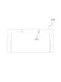
도 1은 본 발명에 따른 치조골을 천공할 때 발생되는 소음 및 마찰력을 감소시키기 위한 무통주사기의 결합 구조를 나타낸 단면도.
도 2는 본 발명에 따른 치조골을 천공할 때 발생되는 소음 및 마찰력을 감소시키기 위한 무통주사기의 바늘이 주입부 부위를 확대하여 나타낸 확대도.
도 3은 본 발명에 따른 치조골을 천공할 때 발생되는 소음 및 마찰력을 감소시키기 위한 무통주사기의 소음 및 마찰력을 감소시키기 위한 부싱을 나타낸 단면도.1 is a cross-sectional view showing a coupling structure of a painless syringe for reducing noise and friction generated when perforating alveolar bone according to the present invention.
2 is an enlarged view showing an enlarged portion of an injection part of a needle of a painless syringe for reducing noise and frictional force generated when perforating alveolar bone according to the present invention.
Figure 3 is a cross-sectional view showing a bushing for reducing the noise and frictional force of the painless syringe for reducing the noise and frictional force generated when perforating the alveolar bone according to the present invention.
본 발명의 구체적 특징 및 이점들은 이하에서 첨부도면을 참조하여 상세히 설명한다. 이에 앞서 본 발명에 관련된 기능 및 그 구성에 대한 구체적인 설명이 본 발명의 요지를 불필요하게 흐릴 수 있다고 판단되는 경우에는 구체적인 설명을 생략하기로 한다.Specific features and advantages of the present invention will be described in detail below with reference to the accompanying drawings. Prior to this, if it is determined that the detailed description of functions and configurations related to the present invention may unnecessarily obscure the gist of the present invention, the detailed description will be omitted.
본 발명은 치조골을 천공할 때 발생되는 소음 및 마찰력을 감소시키기 위한 무통주사기에 관한 것으로서, 더욱 상세하게는 치과 치료를 위해 마취액을 주사할 때 바늘을 회전시켜 치조골을 천공할 때 회전 부위의 마찰에 의해 회전력이 감소되지 않도록 하기 위한 치조골을 천공할 때 발생되는 소음 및 마찰력을 감소시키기 위한 무통주사기에 관한 것이다.The present invention relates to a painless syringe for reducing noise and friction generated when perforating the alveolar bone, and more particularly, when injecting an anesthetic for dental treatment by rotating a needle to perforate the alveolar bone, the friction of the rotation part It relates to a painless syringe for reducing noise and frictional force generated when perforating the alveolar bone so that the rotational force is not reduced by the.
이하, 본 발명의 바람직한 실시 예를 첨부한 도면을 참고로 상세하게 설명하기로 한다.Hereinafter, preferred embodiments of the present invention will be described in detail with reference to the accompanying drawings.
도 1은 본 발명에 따른 치조골을 천공할 때 발생되는 소음 및 마찰력을 감소시키기 위한 무통주사기의 결합 구조를 나타낸 단면도이고, 도 2는 본 발명에 따른 치조골을 천공할 때 발생되는 소음 및 마찰력을 감소시키기 위한 무통주사기의 바늘(110)이 주입부(100) 부위를 확대하여 나타낸 확대도이며, 도 3은 본 발명에 따른 치조골을 천공할 때 발생되는 소음 및 마찰력을 감소시키기 위한 무통주사기의 소음 및 마찰력을 감소시키기 위한 부싱(210)을 나타낸 단면도이다.1 is a cross-sectional view showing a coupling structure of a painless syringe for reducing noise and frictional force generated when perforating alveolar bone according to the present invention, and FIG. 2 is a cross-sectional view showing noise and frictional force generated when perforating alveolar bone according to the present invention. 3 is an enlarged view showing the
도 1 내지 도 3에 도시된 바와 같이, 본 발명에 따른 본 발명에 따른 치조골을 천공할 때 발생되는 소음 및 마찰력을 감소시키기 위한 무통주사기는 치조골을 천공하고 마취액을 분사할 수 있도록 바늘(110)이 형성되는 주입부(100)와, 주입부(100)가 일단에 결합될 수 있도록 형성되고 타단은 개구되어 있어 내부가 비어 있는 홀더(300)와, 홀더(300)에 삽입되도록 형성되며 일단에는 주입부(100)의 바늘(110)이 삽입될 수 있도록 형성되고 타단에는 마취액을 배출시키기 위한 피스톤(410)이 형성된 앰풀(400)과, 홀더(300)를 내부에 삽입하여 수용할 수 있도록 형성되고 홀더(300)의 일단이 외부로 노출될 수 있도록 관통홀이 형성되어 있는 하우징(200)과, 하우징(200)과 결합될 수 있도록 형성되며 앰풀(400), 홀더(300), 주입부(100)를 회전시켜 치조골이 천공되도록 하고, 피스톤(410)을 가압하여 마취액을 분사하는 핸드피스(500)를 포함하는 것을 특징으로 한다.As shown in Figures 1 to 3, the painless syringe for reducing the noise and frictional force generated when perforating the alveolar bone according to the present invention according to the present invention is a needle (110) to perforate the alveolar bone and spray an anesthetic solution. ) is formed, the
또한 주입부(100)는 원통형으로 형성되며 일면은 개구되어 있어 홀더(300)의 일단이 내부로 삽입될 수 있도록 형성되는 지지대(120)와, 지지대(120)의 중앙에 형성되며 지지대(120)의 일면과 타면을 향해 관통되어 앰풀(400) 내부에 수용된 마취액을 배출시키거나 치조골을 천공하도록 형성되는 바늘(110)로 이루어지는 것을 특징으로 한다.In addition, the
또한 핸드피스(500)는 외부 동력에 의해 회전력을 발생시키는 제1구동부(510) 및 제2구동부(520)와, 피스톤(410)과 결합되며 제1구동부(510)에 의해 회전력을 병진운동으로 변환하여 피스톤(410)을 전진 또는 후진시킬 수 있도록 형성되는 제1구동단(511)과, 제2구동부(520)에 의해 앰풀(400)과 결합되어 앰풀(400)을 회전시켜 앰풀(400)과 결합된 홀더(300) 및 주입부(100)를 회전시키는 제2구동단(521)으로 이루어지는 것을 특징으로 한다.In addition, the
주입부(100)는 바늘(110)을 교체하여 사용할 수 있도록 하기 위해 홀더(300)의 일단에 탈부착될 수 있도록 형성되어 있으며, 홀더(300)의 일단 외면에 나사 결합되도록 형성되는 지지대(120)와, 지지대(120)의 중앙 양쪽으로 돌출되어 일단은 치조골을 천공하고 치근관에 마취액을 주사할 수 있도록 형성되고 타단은 홀더(300)를 통해 앰풀(400) 내부로 삽입되어 앰풀(400) 내부에 저장된 마취액을 배출할 수 있도록 형성되어 있다.The
지지대(120)와 바늘(110)은 일체형으로 형성되어 있기 때문에 주사가 완료되거나 시술이 끝나게 되면 주입부(100)를 분리하여 버릴 수 있게 되므로 의료사고를 방지할 수 있게 된다.Since the
또한 바늘(110)의 일단과 타단은 첨단부가 형성되어 있어 일단은 환자의 잇몸 및 치조골에 삽입될 때 저항력을 감소시킬 수 있게 되며, 타단은 앰풀(400)에 삽입될 때 첨단부를 통해 앰풀(400)을 뚫고 앰풀(400) 내부로 삽입될 수 있게 된다.In addition, one end and the other end of the
홀더(300)는 일단은 주입부(100)가 탈부착될 수 있도록 형성되어 있으며 타단은 개구되어 있어 내부에 앰풀(400)을 삽입할 수 있도록 형성되어 있으며, 홀더(300)를 통해 일단에는 주입부(100)가, 타단에는 앰풀(400)이 고정될 수 있게 된다.The
홀더(300)는 일단에는 주입부(100)가 결합될 수 있도록 나사산이 형성된 체결단(310)이 마련되어 있으며, 체결단(310)의 후면에는 하우징(200)에 의해 고정될 수 있도록 형성되는 회전단(320)이 형성되어 있다.The
체결단(310)은 주입부(100)의 지지대(120)와 나사 결합되어 탈부착되기 위해 형성되고, 회전단(320)은 하우징(200)과 접촉되어 홀더(300)의 일단이 하우징(200)에 고정될 수 있도록 하기 위해 형성된다.The fastening
이때 회전단(320)은 핸드피스(500)의 구동부에 의해 홀더(300)가 회전될 때 하우징(200)과 접촉되며 회전되는 부위이며, 마찰력을 감소시키기 위해 외면에는 윤활유가 도포되어 있을 수 있다.At this time, the rotating
앰풀(400)은 홀더(300) 내부에 밀착될 수 있도록 홀더(300) 내부 형상과 동일하게 형성되어 있으며, 앰풀(400)의 일단은 홀더(300) 일단에서 결합되는 주입부(100)의 바늘(110)이 삽입될 수 있도록 고무 재질로 이루어질 수 있다.The
앰풀(400)은 타단이 개구되어 있어 내부에 마취액을 저장할 수 있도록 형성되며, 타단에는 저장된 마취액이 배출되지 않도록 피스톤(410)이 결합되면서 앰풀(400)의 타단을 밀봉시킬 수 있게 된다.The other end of the
하우징(200)은 핸드피스(500)의 일단에 형성되어 있으며 핸드피스(500)로부터 탈부착될 수 있도록 구성되어 있고, 내부에는 주입부(100) 및 앰풀(400)이 결합된 홀더(300)를 탈부착할 수 있도록 형성되어 있다.The
이때 하우징(200)은 일단 중앙에 관통홀이 형성되어 있어 홀더(300)의 일단이 하우징(200) 외부로 돌출될 수 있도록 형성되며 이를 통해 홀더(300) 일단에 결합된 주입부(100)가 외부로 노출될 수 있게 된다.At this time, the
핸드피스(500)는 내부에 자동 주사를 위한 동작을 제어하고 이와 관련된 장치를 수용하기 위해 사용되는 것으로, 기본적으로 사용되는 제어부, 배터리, 디스플레이, 조작부, 스피커, 충전부, 압력센서가 포함되어 있다.The
핸드피스(500)의 구동부는 제1구동부(510)와 제2구동부(520)로 나누어지며, 제1구동부(510)와 제2구동부(520)에는 각각 서로 다른 동작을 수행하기 위한 제1구동단(511)과 제2구동단(521)이 형성되어 있다.The driving unit of the
여기서 제1구동부(510)와 제2구동부(520)는 배터리로부터 전력을 제공받아 회전력을 발생시키기 위해 사용되는 것이다.Here, the
제1구동단(511)은 앰풀(400) 내부에 형성된 피스톤(410)과 결합될 수 있도록 형성되어 있으며 제1구동부(510)로부터 회전력을 전달받으면 이를 병진운동으로 변환하여 상부 또는 하부로 이동되어 피스톤(410)을 이동시킬 수 있게 된다.The
제2구동단(521)은 앰풀(400)의 타단과 결합되어 제2구동부(520)로부터 회전력을 전달받으면 이를 앰풀(400)에 전달하여 앰풀(400)을 회전시킴으로써, 앰풀(400)과 결합된 홀더(300) 및 주입부(100)를 회전시켜 주입부(100)의 바늘(110)이 치조골을 천공할 수 있도록 한다.When the
이때 제2구동단(521)은 앰풀(400)이 아닌 홀더(300)에 결합되어 회전시킬 수도 있다.At this time, the
제2구동단(521)은 중공형태로 이루어져 있어 중앙에 제1구동단(511)이 위치될 수 있도록 할 수 있다.The
또한 하우징(200)의 타단이 핸드피스(500)에 결합되면 하우징(200)의 내부에 위치된 앰풀(400)은 핸드피스(500) 내부에 형성된 제1구동단(511)과 동일 축 선상에 위치되게 되고, 핸드피스(500)의 제1구동부(510)에 의해 제1구동단(511)이 이송되면 피스톤(410)의 후면과 결합되게 된다.In addition, when the other end of the
제2구동단(521)도 이와 마찬가지로 하우징(200)이 결합될 때 제2구동단(521)이 앰풀(400) 또는 홀더(300)와 결합될 수 있도록 형성되는 것이 바람직하다.Similarly, the
또한 하우징(200)의 내경은 홀더(300)의 외경보다 크게 형성되어 있어 홀더(300)가 내부에 삽입되면 하우징(200)의 내측면과 접촉되지 않도록 하여 접촉부위를 감소시키고 홀더(300)의 일단 외면과 접촉되어 홀더(300)를 지지하는 것을 특징으로 한다.In addition, the inner diameter of the
하우징(200)의 내면은 홀더(300)의 외면과 접촉되지 않고 이격된 상태로 형성되어 있으며, 하우징(200)의 일단에 형성된 관통홀에만 홀더(300)의 일단이 삽입되면서 접촉되게 된다.The inner surface of the
이때 홀더(300)의 회전단(320)은 하우징(200)의 관통홀에 삽입되어 접촉된 상태로 결합되며, 홀더(300)의 타단은 핸드피스(500)에 형성된 제1구동단(511) 및 제2구동단(521)에 의해 지지되어 위치가 고정될 수 있게 된다.At this time, the
하우징(200)이 홀더(300)와 이격된 상태로 유지시키기 위해 하우징(200)의 내경은 홀더(300)의 외경보다 크게 형성되도록 하여 간극에 의해 홀더(300)가 회전할 때 간섭이나 마찰력이 발생되지 않도록 방지할 수 있게 된다.In order to keep the
또한 하우징(200)의 일단에 형성되며 홀더(300)의 일단에 형성된 지지단과 접촉되어 홀더(300)가 회전될 때 발생하는 마찰력을 감소시키는 부싱(210)을 더 포함하는 것을 특징으로 한다.In addition, it is formed on one end of the
부싱(210)은 하우징(200)의 일단 부분을 모듈화하여 사용하기 위한 것으로, 하우징(200)의 일단에 관통홀이 형성된 부위를 부싱(210)으로 대체 될 수 있게 된다.The
이 경우 부싱(210)은 일면에는 홀더(300)의 회전단(320)이 삽입될 수 있도록 관통홀이 형성되어 있고 타면에는 하우징(200)의 외면과 나사 결합할 수 있도록 형성되게 된다.In this case, the
부싱(210)은 하우징(200)과 탈부착이 가능하기 때문에 홀더(300)가 회전될 때 회전단(320)과 접촉되는 부위의 마모가 발생하더라도, 하우징(200)으로부터 마모된 부싱(210)을 분리시키고 새로운 부싱(210)을 결합하여 사용할 수 있으므로 유지보수가 간결해질 수 있게 된다.Since the
또한 부싱(210)은 접촉 면적이 감소될 수 있도록 접촉부위가 원형으로 라운딩 처리되는 것을 특징으로 한다.In addition, the
또한 부싱(210)은 마찰력을 감소시키기 위한 윤활유가 배출되거나 수용할 수 있도록 접촉면에 내측으로 파여지는 윤활홀(211)을 더 포함하는 것을 특징으로 한다.In addition, the
또한 부싱(210)은 플라스틱 베어링으로 형성되어 무게를 감소시키고 마찰에 의해 발생되는 소음을 감소시키는 것을 특징으로 한다.In addition, the
부싱(210)은 무게감소와 접촉되는 홀더(300)의 마모를 방지하기 위해 플라스틱 재질로 이루어질 수 있으며, 베어링 역할을 통해 회전되는 홀더(300)를 안정적으로 지지하고 접촉부위의 마찰력에 의한 홀더(300)의 회전속도저하를 방지할 수 있게 된다.The
또한 부싱(210)을 통해 마찰력을 감소시킴으로써 마찰에 의해 발생되는 열이나 소음을 감소시킬 수 있게 된다.In addition, by reducing frictional force through the
특히 홀더(300)의 회전단(320)과 접촉되는 부위는 라운딩 처리하여 접촉면적이 최소화 시킬 수 있게 되며, 윤활유를 공급하여 수용할 수 있도록 접촉부위의 중앙에는 내측으로 파여진 윤활홀(211)이 형성될 수 있다.In particular, the area in contact with the
윤활홀(211)에는 윤활유가 수용되어 있어 회전단(320)과 접촉되는 부위에 윤활유가 도포되면서 접촉부위의 마찰을 감소시킬 수 있게 된다.Lubricating oil is accommodated in the
또한 윤활홀(211)은 모세관과 같은 형태로 구성되어 있어 윤활유가 중력에 의해 흘러내리지 않고 윤활홀(211) 내부에 수용된 상태로 저장될 수 있게 되며, 회전단(320)과 접촉되면서 표면장력에 의해 회전단(320) 표면으로 묻어나와 윤활성을 유지하게 된다.In addition, the
이때 회전단(320) 표면에 윤활유가 마른 경우에는 윤활홀(211)에 수용된 윤활유가 표면장력에 의해 회전단(320)과 접촉되면서 일부가 표면장력에 의해 흘러나오게 되며, 이를 통해 적절한 양의 윤활유가 회전단(320)에 도포될 수 있게 유도될 수 있다.At this time, when the lubricating oil is dry on the surface of the
상술한 바와 같이, 본 발명에 따른 치조골을 천공할 때 발생되는 소음 및 마찰력을 감소시키기 위한 무통주사기에 의하면, 마취액을 주입할 때 바늘이 회전되면서 치조골을 천공하여 치근관에 직접 주사할 수 있고, 바늘이 회전될 때 회전부위의 접촉 면적에 의한 마찰력에 의해 회전력이 감소되지 않도록 방지하여 안정적으로 천공이 가능하며, 회전 부위의 소음을 감소시키고 마모 발생을 감소시켜 장시간 사용이 가능한 치조골을 천공할 때 발생되는 소음 및 마찰력을 감소시킬 수 있는 효과가 있다.As described above, according to the painless syringe for reducing the noise and friction generated when perforating the alveolar bone according to the present invention, when the anesthetic is injected, the needle rotates to perforate the alveolar bone and directly inject it into the root canal. , When the needle rotates, it prevents the rotational force from being reduced by the frictional force caused by the contact area of the rotating part, enabling stable drilling. It has the effect of reducing the noise and frictional force generated when
이상과 같이 본 발명은, 바람직한 실시 예를 중심으로 설명하였지만 본 발명이 속하는 기술분야에서 통상의 지식을 가진 자가 본 발명의 특허청구범위에 기재된 기술적 사상 및 영역으로부터 벗어나지 않는 범위 내에서 본 발명을 다양하게 수정 또는 변형하여 실시할 수 있다. 따라서 본 발명의 범주는 이러한 많은 변형의 예들을 포함하도록 기술된 청구범위에 의해서 해석되어야 한다.As described above, the present invention has been described with a focus on preferred embodiments, but those skilled in the art can make the present invention various within the range that does not deviate from the technical spirit and scope described in the claims of the present invention. It can be implemented by modifying or transforming accordingly. Accordingly, the scope of the present invention should be construed by the claims which are written to include examples of these many variations.
100 : 주입부
110 : 바늘
120 : 지지대
200 : 하우징
210 : 부싱
211 : 윤활홀
300 : 홀더
310 : 체결단
320 : 회전단
400 : 앰풀
410 : 피스톤
500 : 핸드피스
510 : 제1구동부
511 : 제1구동단
520 : 제2구동부
521 : 제2구동단100: injection part
110: needle
120: support
200: housing
210: bushing
211: lubrication hole
300: holder
310: fastening end
320: rotating end
400: ampoule
410: piston
500: handpiece
510: first driving unit
511: first drive stage
520: second driving unit
521: second drive stage
Claims (6)
Translated fromKorean상기 주입부가 일단에 결합될 수 있도록 형성되고 타단은 개구되어 있어 내부가 비어 있는 홀더와;
상기 홀더에 삽입되도록 형성되며 일단에는 상기 주입부의 바늘이 삽입될 수 있도록 형성되고 타단에는 상기 마취액을 배출시키기 위한 피스톤이 형성된 앰풀과;
상기 홀더를 내부에 삽입하여 수용할 수 있도록 형성되고 상기 홀더의 일단이 외부로 노출될 수 있도록 관통홀이 형성되어 있는 하우징과;
상기 하우징과 결합될 수 있도록 형성되며 상기 앰풀, 상기 홀더, 상기 주입부를 회전시켜 치조골이 천공되도록 하고, 상기 피스톤을 가압하여 상기 마취액을 분사하는 핸드피스;를 포함하는 것을 특징으로 하는
치조골을 천공할 때 발생되는 소음 및 마찰력을 감소시키기 위한 무통주사기.
an injection unit in which a needle is formed to pierce the alveolar bone and spray an anesthetic solution;
a holder whose inside is empty since the injection part is formed to be coupled to one end and the other end is open;
an ampoule formed to be inserted into the holder, one end formed so that the needle of the injection unit can be inserted, and the other end formed with a piston for discharging the anesthetic liquid;
a housing formed to accommodate the holder by being inserted therein and having a through hole through which one end of the holder is exposed to the outside;
A handpiece formed to be coupled with the housing, rotates the ampoule, the holder, and the injection unit to perforate the alveolar bone, and pressurizes the piston to spray the anesthetic solution.
A painless syringe to reduce the noise and friction generated when perforating the alveolar bone.
상기 하우징의 내경은 상기 홀더의 외경보다 크게 형성되어 있어 상기 홀더가 내부에 삽입되면 상기 하우징의 내측면과 접촉되지 않도록 하여 접촉부위를 감소시키고 상기 홀더의 일단 외면과 접촉되어 상기 홀더를 지지하는 것을 특징으로 하는
치조골을 천공할 때 발생되는 소음 및 마찰력을 감소시키기 위한 무통주사기.
According to claim 1,
The inner diameter of the housing is formed larger than the outer diameter of the holder so that when the holder is inserted inside, it does not come into contact with the inner surface of the housing to reduce the contact area and support the holder by contacting one end of the holder with the outer surface characterized
A painless syringe to reduce the noise and friction generated when perforating the alveolar bone.
상기 하우징의 일단에 형성되며
상기 홀더의 일단에 형성된 지지단과 접촉되어 상기 홀더가 회전될 때 발생하는 마찰력을 감소시키는 부싱;을 더 포함하는 것을 특징으로 하는
치조골을 천공할 때 발생되는 소음 및 마찰력을 감소시키기 위한 무통주사기.
According to claim 1,
It is formed at one end of the housing
And a bushing contacting the support end formed at one end of the holder to reduce the frictional force generated when the holder rotates.
A painless syringe to reduce the noise and friction generated when perforating the alveolar bone.
상기 부싱은 접촉면적이 감소될 수 있도록 접촉부위가 원형으로 라운딩 처리되는 것을 특징으로 하는
치조골을 천공할 때 발생되는 소음 및 마찰력을 감소시키기 위한 무통주사기.
According to claim 3,
The bushing is characterized in that the contact area is rounded in a circular shape so that the contact area can be reduced
A painless syringe to reduce the noise and friction generated when perforating the alveolar bone.
상기 부싱은 마찰력을 감소시키기 위한 윤활유가 배출되거나 수용할 수 있도록 접촉면에 내측으로 파여지는 윤활홀;을 더 포함하는 것을 특징으로 하는
치조골을 천공할 때 발생되는 소음 및 마찰력을 감소시키기 위한 무통주사기.
According to claim 3,
The bushing further comprises a lubrication hole cut into the contact surface so that the lubricating oil for reducing frictional force can be discharged or received.
A painless syringe to reduce the noise and friction generated when perforating the alveolar bone.
상기 부싱은 플라스틱 베어링으로 형성되어 무게를 감소시키고 마찰에 의해 발생되는 소음을 감소시키는 것을 특징으로 하는
치조골을 천공할 때 발생되는 소음 및 마찰력을 감소시키기 위한 무통주사기.According to claim 3,
The bushing is formed of a plastic bearing to reduce weight and reduce noise generated by friction.
A painless syringe to reduce the noise and friction generated when perforating the alveolar bone.
Priority Applications (2)
| Application Number | Priority Date | Filing Date | Title |
|---|---|---|---|
| KR1020210104995AKR20230023153A (en) | 2021-08-10 | 2021-08-10 | Painless syringe to reduce the noise and friction generated when perforating the alveolar bone |
| US17/471,103US20230046804A1 (en) | 2021-08-10 | 2021-09-09 | Painless syringe to reduce the noise and friction generated when perforating the alveolar bone |
Applications Claiming Priority (1)
| Application Number | Priority Date | Filing Date | Title |
|---|---|---|---|
| KR1020210104995AKR20230023153A (en) | 2021-08-10 | 2021-08-10 | Painless syringe to reduce the noise and friction generated when perforating the alveolar bone |
Publications (1)
| Publication Number | Publication Date |
|---|---|
| KR20230023153Atrue KR20230023153A (en) | 2023-02-17 |
Family
ID=85178094
Family Applications (1)
| Application Number | Title | Priority Date | Filing Date |
|---|---|---|---|
| KR1020210104995AAbandonedKR20230023153A (en) | 2021-08-10 | 2021-08-10 | Painless syringe to reduce the noise and friction generated when perforating the alveolar bone |
Country Status (2)
| Country | Link |
|---|---|
| US (1) | US20230046804A1 (en) |
| KR (1) | KR20230023153A (en) |
Citations (1)
| Publication number | Priority date | Publication date | Assignee | Title |
|---|---|---|---|---|
| KR20190101062A (en) | 2018-02-22 | 2019-08-30 | 메디허브 주식회사 | Automatic injector |
Family Cites Families (14)
| Publication number | Priority date | Publication date | Assignee | Title |
|---|---|---|---|---|
| US4518384A (en)* | 1983-06-17 | 1985-05-21 | Survival Technology, Inc. | Multiple medicament cartridge clip and medicament discharging device therefor |
| FR2581548B1 (en)* | 1985-05-09 | 1990-07-20 | Villette Alain | DEVICE FOR INTRAOSUS INJECTION OF BIOCOMPATIBLE PRODUCTS |
| JP4245350B2 (en)* | 2001-01-18 | 2009-03-25 | メドラッド インコーポレーテッド | Syringe interface and syringe adapter for use in medical injectors |
| US7811260B2 (en)* | 2002-05-31 | 2010-10-12 | Vidacare Corporation | Apparatus and method to inject fluids into bone marrow and other target sites |
| US20040147901A1 (en)* | 2002-07-08 | 2004-07-29 | Medical Instill | Intradermal delivery device, and method of intradermal delivery |
| HUE060243T2 (en)* | 2006-09-15 | 2023-02-28 | Ypsomed Ag | Injection device comprising an improved delivery element |
| CN103041478B (en)* | 2008-04-10 | 2015-01-21 | 松下健康医疗控股株式会社 | Medication administering device |
| WO2010150396A1 (en)* | 2009-06-26 | 2010-12-29 | 昭和薬品化工株式会社 | Linear dental electric syringe |
| JP2013501584A (en)* | 2009-08-13 | 2013-01-17 | マリンクロッド エルエルシー | Electric injector syringe assembly |
| FR2954169B1 (en)* | 2009-12-17 | 2012-12-14 | Dentalhitec | SURGICAL INSTRUMENT FOR INJECTING A PHARMACEUTICAL PRODUCT THROUGH A DENSE FABRIC OF A HUMAN OR ANIMAL BODY AND METHOD OF PERFORATING SUCH A DENSE FABRIC |
| TWI459986B (en)* | 2010-11-08 | 2014-11-11 | Shl Group Ab | Container holder assembly |
| EP2698181B1 (en)* | 2011-04-12 | 2016-08-31 | Showa Yakuhin Kako Co., Ltd. | Electric syringe to be used with two kinds of dental anesthetic solution-containing cartridges |
| US20200360053A1 (en)* | 2018-04-03 | 2020-11-19 | Dr. Barney Paradigms, Lc | Device and method for intraosseous dental anesthetization |
| EP4072625B1 (en)* | 2019-12-09 | 2023-08-16 | SHL Medical AG | Assembly, cassette and medicament delivery device |
- 2021
- 2021-08-10KRKR1020210104995Apatent/KR20230023153A/ennot_activeAbandoned
- 2021-09-09USUS17/471,103patent/US20230046804A1/ennot_activeAbandoned
Patent Citations (1)
| Publication number | Priority date | Publication date | Assignee | Title |
|---|---|---|---|---|
| KR20190101062A (en) | 2018-02-22 | 2019-08-30 | 메디허브 주식회사 | Automatic injector |
Also Published As
| Publication number | Publication date |
|---|---|
| US20230046804A1 (en) | 2023-02-16 |
Similar Documents
| Publication | Publication Date | Title |
|---|---|---|
| JP4031053B2 (en) | Medication injection device | |
| US4747824A (en) | Hypodermic anesthetic injection method | |
| US5180371A (en) | Hypodermic anesthetic injection apparatus and method | |
| EP0429440B1 (en) | Aspirating hypodermic syringe apparatus | |
| US6520928B1 (en) | Medical liquid injection system and method | |
| JP5996021B2 (en) | Device for delivering liquid medication | |
| US6113574A (en) | Anesthetic injection apparatus and methods | |
| CN101500453B (en) | tattoo device | |
| US4578055A (en) | Controlled diffusion medicament applicator | |
| JP2005515034A (en) | Drug injection device having lead screw detachable in axial direction | |
| ES2090339T3 (en) | PREVIOUSLY FILLED USE AND DISPOSAL DEVICE FOR INTRODUCING A PHARMACOLOGICALLY ACTIVE SUBSTANCE IN A PATIENT'S BODY CAVITY, METHOD FOR MANUFACTURING SUCH DEVICE AND MOLDING DEVICE TO MANUFACTURE SUCH A DEVICE. | |
| KR101370430B1 (en) | Ampoule holder of dental anesthesia liquid injection device and dental anesthesia liquid injection device having the same | |
| KR101648056B1 (en) | Apparatus for injecting automatic drug | |
| US6152734A (en) | Dental anesthetic and delivery injection unit | |
| KR20230023153A (en) | Painless syringe to reduce the noise and friction generated when perforating the alveolar bone | |
| KR20230023154A (en) | Painless syringe with anti-slip structure for perforating alveolar bone and injecting anesthetic | |
| KR20140142084A (en) | Apparatus for injecting medicine | |
| KR102637080B1 (en) | Quantitative fixed rate drug injection method and painless anesthesia injection device according thereto | |
| CN102125455B (en) | Surgical instruments | |
| WO2019224991A1 (en) | Capillary blood collection device | |
| JP4994167B2 (en) | Dental anesthesia syringe | |
| FR2735031A1 (en) | Local anaesthetic injection apparatus | |
| KR101288950B1 (en) | Apparatus for injecting medicine | |
| KR102777933B1 (en) | Pharmaceutical solution injection device for skin treatment | |
| RU66958U1 (en) | ROTARY DENTAL SYRINGE |
Legal Events
| Date | Code | Title | Description |
|---|---|---|---|
| PA0109 | Patent application | St.27 status event code:A-0-1-A10-A12-nap-PA0109 | |
| PA0201 | Request for examination | St.27 status event code:A-1-2-D10-D11-exm-PA0201 | |
| D13-X000 | Search requested | St.27 status event code:A-1-2-D10-D13-srh-X000 | |
| D14-X000 | Search report completed | St.27 status event code:A-1-2-D10-D14-srh-X000 | |
| E902 | Notification of reason for refusal | ||
| PE0902 | Notice of grounds for rejection | St.27 status event code:A-1-2-D10-D21-exm-PE0902 | |
| P11-X000 | Amendment of application requested | St.27 status event code:A-2-2-P10-P11-nap-X000 | |
| P13-X000 | Application amended | St.27 status event code:A-2-2-P10-P13-nap-X000 | |
| PG1501 | Laying open of application | St.27 status event code:A-1-1-Q10-Q12-nap-PG1501 | |
| E701 | Decision to grant or registration of patent right | ||
| PE0701 | Decision of registration | St.27 status event code:A-1-2-D10-D22-exm-PE0701 | |
| PC1904 | Unpaid initial registration fee | St.27 status event code:A-2-2-U10-U13-oth-PC1904 St.27 status event code:N-2-6-B10-B12-nap-PC1904 |