KR20230019977A - Cleaning unit for cleaning the chamber exhaust - Google Patents
Cleaning unit for cleaning the chamber exhaustDownload PDFInfo
- Publication number
- KR20230019977A KR20230019977AKR1020237000764AKR20237000764AKR20230019977AKR 20230019977 AKR20230019977 AKR 20230019977AKR 1020237000764 AKR1020237000764 AKR 1020237000764AKR 20237000764 AKR20237000764 AKR 20237000764AKR 20230019977 AKR20230019977 AKR 20230019977A
- Authority
- KR
- South Korea
- Prior art keywords
- chamber
- cleaning module
- plasma
- module
- cleaning
- Prior art date
- Legal status (The legal status is an assumption and is not a legal conclusion. Google has not performed a legal analysis and makes no representation as to the accuracy of the status listed.)
- Granted
Links
Images


Classifications
- H—ELECTRICITY
- H01—ELECTRIC ELEMENTS
- H01J—ELECTRIC DISCHARGE TUBES OR DISCHARGE LAMPS
- H01J37/00—Discharge tubes with provision for introducing objects or material to be exposed to the discharge, e.g. for the purpose of examination or processing thereof
- H01J37/32—Gas-filled discharge tubes
- H01J37/32431—Constructional details of the reactor
- H01J37/32798—Further details of plasma apparatus not provided for in groups H01J37/3244 - H01J37/32788; special provisions for cleaning or maintenance of the apparatus
- H01J37/32853—Hygiene
- H01J37/32862—In situ cleaning of vessels and/or internal parts
- C—CHEMISTRY; METALLURGY
- C23—COATING METALLIC MATERIAL; COATING MATERIAL WITH METALLIC MATERIAL; CHEMICAL SURFACE TREATMENT; DIFFUSION TREATMENT OF METALLIC MATERIAL; COATING BY VACUUM EVAPORATION, BY SPUTTERING, BY ION IMPLANTATION OR BY CHEMICAL VAPOUR DEPOSITION, IN GENERAL; INHIBITING CORROSION OF METALLIC MATERIAL OR INCRUSTATION IN GENERAL
- C23C—COATING METALLIC MATERIAL; COATING MATERIAL WITH METALLIC MATERIAL; SURFACE TREATMENT OF METALLIC MATERIAL BY DIFFUSION INTO THE SURFACE, BY CHEMICAL CONVERSION OR SUBSTITUTION; COATING BY VACUUM EVAPORATION, BY SPUTTERING, BY ION IMPLANTATION OR BY CHEMICAL VAPOUR DEPOSITION, IN GENERAL
- C23C16/00—Chemical coating by decomposition of gaseous compounds, without leaving reaction products of surface material in the coating, i.e. chemical vapour deposition [CVD] processes
- C23C16/44—Chemical coating by decomposition of gaseous compounds, without leaving reaction products of surface material in the coating, i.e. chemical vapour deposition [CVD] processes characterised by the method of coating
- C23C16/4412—Details relating to the exhausts, e.g. pumps, filters, scrubbers, particle traps
- H—ELECTRICITY
- H01—ELECTRIC ELEMENTS
- H01J—ELECTRIC DISCHARGE TUBES OR DISCHARGE LAMPS
- H01J37/00—Discharge tubes with provision for introducing objects or material to be exposed to the discharge, e.g. for the purpose of examination or processing thereof
- H01J37/32—Gas-filled discharge tubes
- H01J37/32009—Arrangements for generation of plasma specially adapted for examination or treatment of objects, e.g. plasma sources
- H01J37/32192—Microwave generated discharge
- H01J37/32211—Means for coupling power to the plasma
- H—ELECTRICITY
- H01—ELECTRIC ELEMENTS
- H01J—ELECTRIC DISCHARGE TUBES OR DISCHARGE LAMPS
- H01J37/00—Discharge tubes with provision for introducing objects or material to be exposed to the discharge, e.g. for the purpose of examination or processing thereof
- H01J37/32—Gas-filled discharge tubes
- H01J37/32009—Arrangements for generation of plasma specially adapted for examination or treatment of objects, e.g. plasma sources
- H01J37/32357—Generation remote from the workpiece, e.g. down-stream
- H—ELECTRICITY
- H01—ELECTRIC ELEMENTS
- H01J—ELECTRIC DISCHARGE TUBES OR DISCHARGE LAMPS
- H01J37/00—Discharge tubes with provision for introducing objects or material to be exposed to the discharge, e.g. for the purpose of examination or processing thereof
- H01J37/32—Gas-filled discharge tubes
- H01J37/32431—Constructional details of the reactor
- H01J37/3244—Gas supply means
- H01J37/32449—Gas control, e.g. control of the gas flow
- H—ELECTRICITY
- H01—ELECTRIC ELEMENTS
- H01J—ELECTRIC DISCHARGE TUBES OR DISCHARGE LAMPS
- H01J37/00—Discharge tubes with provision for introducing objects or material to be exposed to the discharge, e.g. for the purpose of examination or processing thereof
- H01J37/32—Gas-filled discharge tubes
- H01J37/32431—Constructional details of the reactor
- H01J37/32798—Further details of plasma apparatus not provided for in groups H01J37/3244 - H01J37/32788; special provisions for cleaning or maintenance of the apparatus
- H01J37/32816—Pressure
- H01J37/32834—Exhausting
- H01J37/32844—Treating effluent gases
- H—ELECTRICITY
- H01—ELECTRIC ELEMENTS
- H01J—ELECTRIC DISCHARGE TUBES OR DISCHARGE LAMPS
- H01J37/00—Discharge tubes with provision for introducing objects or material to be exposed to the discharge, e.g. for the purpose of examination or processing thereof
- H01J37/32—Gas-filled discharge tubes
- H01J37/32431—Constructional details of the reactor
- H01J37/32798—Further details of plasma apparatus not provided for in groups H01J37/3244 - H01J37/32788; special provisions for cleaning or maintenance of the apparatus
- H01J37/3288—Maintenance
- H—ELECTRICITY
- H01—ELECTRIC ELEMENTS
- H01J—ELECTRIC DISCHARGE TUBES OR DISCHARGE LAMPS
- H01J37/00—Discharge tubes with provision for introducing objects or material to be exposed to the discharge, e.g. for the purpose of examination or processing thereof
- H01J37/32—Gas-filled discharge tubes
- H01J37/32431—Constructional details of the reactor
- H01J37/32798—Further details of plasma apparatus not provided for in groups H01J37/3244 - H01J37/32788; special provisions for cleaning or maintenance of the apparatus
- H01J37/32889—Connection or combination with other apparatus
- H—ELECTRICITY
- H05—ELECTRIC TECHNIQUES NOT OTHERWISE PROVIDED FOR
- H05H—PLASMA TECHNIQUE; PRODUCTION OF ACCELERATED ELECTRICALLY-CHARGED PARTICLES OR OF NEUTRONS; PRODUCTION OR ACCELERATION OF NEUTRAL MOLECULAR OR ATOMIC BEAMS
- H05H1/00—Generating plasma; Handling plasma
- H05H1/24—Generating plasma
- H05H1/46—Generating plasma using applied electromagnetic fields, e.g. high frequency or microwave energy
- B—PERFORMING OPERATIONS; TRANSPORTING
- B08—CLEANING
- B08B—CLEANING IN GENERAL; PREVENTION OF FOULING IN GENERAL
- B08B7/00—Cleaning by methods not provided for in a single other subclass or a single group in this subclass
- B08B7/0035—Cleaning by methods not provided for in a single other subclass or a single group in this subclass by radiant energy, e.g. UV, laser, light beam or the like
- C—CHEMISTRY; METALLURGY
- C23—COATING METALLIC MATERIAL; COATING MATERIAL WITH METALLIC MATERIAL; CHEMICAL SURFACE TREATMENT; DIFFUSION TREATMENT OF METALLIC MATERIAL; COATING BY VACUUM EVAPORATION, BY SPUTTERING, BY ION IMPLANTATION OR BY CHEMICAL VAPOUR DEPOSITION, IN GENERAL; INHIBITING CORROSION OF METALLIC MATERIAL OR INCRUSTATION IN GENERAL
- C23C—COATING METALLIC MATERIAL; COATING MATERIAL WITH METALLIC MATERIAL; SURFACE TREATMENT OF METALLIC MATERIAL BY DIFFUSION INTO THE SURFACE, BY CHEMICAL CONVERSION OR SUBSTITUTION; COATING BY VACUUM EVAPORATION, BY SPUTTERING, BY ION IMPLANTATION OR BY CHEMICAL VAPOUR DEPOSITION, IN GENERAL
- C23C16/00—Chemical coating by decomposition of gaseous compounds, without leaving reaction products of surface material in the coating, i.e. chemical vapour deposition [CVD] processes
- C23C16/44—Chemical coating by decomposition of gaseous compounds, without leaving reaction products of surface material in the coating, i.e. chemical vapour deposition [CVD] processes characterised by the method of coating
- C23C16/4401—Means for minimising impurities, e.g. dust, moisture or residual gas, in the reaction chamber
- C23C16/4405—Cleaning of reactor or parts inside the reactor by using reactive gases
- H—ELECTRICITY
- H05—ELECTRIC TECHNIQUES NOT OTHERWISE PROVIDED FOR
- H05H—PLASMA TECHNIQUE; PRODUCTION OF ACCELERATED ELECTRICALLY-CHARGED PARTICLES OR OF NEUTRONS; PRODUCTION OR ACCELERATION OF NEUTRAL MOLECULAR OR ATOMIC BEAMS
- H05H1/00—Generating plasma; Handling plasma
- H05H1/24—Generating plasma
- H05H1/46—Generating plasma using applied electromagnetic fields, e.g. high frequency or microwave energy
- H05H1/461—Microwave discharges
- H05H1/463—Microwave discharges using antennas or applicators
Landscapes
- Chemical & Material Sciences (AREA)
- Physics & Mathematics (AREA)
- Engineering & Computer Science (AREA)
- Plasma & Fusion (AREA)
- Analytical Chemistry (AREA)
- Public Health (AREA)
- Epidemiology (AREA)
- Health & Medical Sciences (AREA)
- Organic Chemistry (AREA)
- Metallurgy (AREA)
- Mechanical Engineering (AREA)
- Materials Engineering (AREA)
- Chemical Kinetics & Catalysis (AREA)
- General Chemical & Material Sciences (AREA)
- Optics & Photonics (AREA)
- Electromagnetism (AREA)
- Spectroscopy & Molecular Physics (AREA)
- Drying Of Semiconductors (AREA)
- Plasma Technology (AREA)
- Cleaning In General (AREA)
- Chemical Vapour Deposition (AREA)
Abstract
Translated fromKoreanDescription
Translated fromKorean본 출원은 2020년 6월 10일에 출원된 미국 정규 출원 번호 16/898,244에 대한 우선권을 주장하며, 이 출원의 전체 내용들은 이로써 본 명세서에 참조로 통합된다.This application claims priority to US Provisional Application Serial No. 16/898,244, filed on June 10, 2020, the entire contents of which are hereby incorporated herein by reference.
실시예들은 진공 챔버(chamber)들에 관한 것으로서, 보다 특히 챔버 배기장치들을 위한 세정 유닛(unit)들에 관한 것이다.Embodiments relate to vacuum chambers, and more particularly to cleaning units for chamber exhausts.
반도체 제조에서, 챔버 프로세스(process)들은 배기 라인(line)에 원치 않는 침전물들을 발생시킬 수 있다. 원치 않는 침전물들은 시간이 지남에 따라 축적되어, 도구 성능에 부정적인 영향을 미칠 수 있다. 예를 들어, 이러한 축적은 배기 라인 컨덕턴스(conductance)가 감소하게 하고 및/또는 배기 라인을 따른 컴포넌트들이 고장 나게 할 수 있다. 배기 라인의 스로틀 밸브(throttle valve)는 특히 이러한 축적들에 취약하다.In semiconductor manufacturing, chamber processes can create unwanted deposits in exhaust lines. Unwanted deposits can build up over time, negatively impacting tool performance. For example, this accumulation can cause the exhaust line conductance to decrease and/or cause components along the exhaust line to fail. The throttle valve in the exhaust line is particularly vulnerable to these accumulations.
현재, 스로틀 밸브 또는 배기 라인의 다른 컴포넌트들로부터 침전물들을 세정하기 위한 솔루션(solution)은 없다. 현재 이용 가능한 유일한 해결책은 스로틀 밸브를 교체하는 것이다. 스로틀 밸브를 교체하는 것은 프로세싱 도구에 상당한 가동 중지 시간을 필요로 하므로, 이에 따라 유지보수에 비용이 많이 든다.Currently, there is no solution for cleaning deposits from the throttle valve or other components of the exhaust line. The only solution currently available is to replace the throttle valve. Replacing the throttle valve requires significant downtime for the processing tool, making maintenance expensive.
본 명세서에 개시된 실시예들은 챔버의 배기 라인을 위한 세정 모듈(module)을 포함한다. 실시예에서, 이동식 세정 모듈은 챔버를 포함하고, 여기서 챔버는 제1 개구 및 제2 개구를 포함한다. 실시예에서, 세정 모듈은 제1 개구를 밀봉하기 위한 리드(lid)를 더 포함한다. 실시예에서, 리드는 유전체 플레이트(plate), 유전체 플레이트에 결합된 유전체 공진기, 유전체 공진기 내부의 구멍에 포지셔닝(position)된 모노폴 안테나(monopole antenna), 및 유전체 공진기를 둘러싸는 전도성 층을 포함한다.Embodiments disclosed herein include a cleaning module for the exhaust line of a chamber. In an embodiment, the mobile cleaning module includes a chamber, wherein the chamber includes a first opening and a second opening. In an embodiment, the cleaning module further includes a lid for sealing the first opening. In an embodiment, the lid includes a dielectric plate, a dielectric resonator coupled to the dielectric plate, a monopole antenna positioned in a hole inside the dielectric resonator, and a conductive layer surrounding the dielectric resonator.
본 명세서에 개시된 추가적인 실시예는 챔버의 배기 라인을 위한 이동식 세정 조립체를 포함한다. 실시예에서, 이동식 세정 조립체는 카트(cart), 및 카트 상의 솔리드 스테이트 일렉트로닉스(solid state electronics) 모듈을 포함하고, 여기서 솔리드 스테이트 일렉트로닉스 모듈은 마이크로파 전자기 방사선을 생성하도록 구성된다. 실시예에서, 조립체는 카트 상에 있고 솔리드 스테이트 일렉트로닉스 모듈에 전기적으로 결합된 프로세서(processor), 및 플라즈마(plasma) 세정 모듈을 더 포함한다. 실시예에서, 플라즈마 세정 모듈은 솔리드 스테이트 일렉트로닉스 모듈에 전기적으로 결합된다.Additional embodiments disclosed herein include a mobile cleaning assembly for the exhaust line of a chamber. In an embodiment, a mobile cleaning assembly includes a cart and a solid state electronics module on the cart, wherein the solid state electronics module is configured to generate microwave electromagnetic radiation. In an embodiment, the assembly further includes a processor on the cart and electrically coupled to the solid state electronics module, and a plasma cleaning module. In an embodiment, the plasma cleaning module is electrically coupled to the solid state electronics module.
본 명세서에 개시된 추가적인 실시예는 배기 라인 상에 세정 모듈을 갖는 프로세싱 도구를 포함한다. 실시예에서, 프로세싱 도구는 기판을 지지하기 위한 페데스탈(pedestal)을 갖는 제1 챔버, 및 제1 챔버에 유체 결합된 배기 라인을 포함한다. 실시예에서, 배기 라인은 펌프(pump), 제1 챔버와 펌프 사이의 메인(main) 배기 라인, 메인 배기 라인에 포지셔닝된 스로틀 밸브, 및 메인 배기 라인에 유체 결합된 세정 라인을 포함한다. 실시예에서, 제2 챔버는 세정 라인에 유체 결합되고, 플라즈마 소스가 제2 챔버에서 플라즈마를 생성하기 위해 제공된다.Additional embodiments disclosed herein include a processing tool having a cleaning module on an exhaust line. In an embodiment, a processing tool includes a first chamber having a pedestal for supporting a substrate, and an exhaust line fluidly coupled to the first chamber. In an embodiment, the exhaust line includes a pump, a main exhaust line between the first chamber and the pump, a throttle valve positioned on the main exhaust line, and a cleaning line fluidly coupled to the main exhaust line. In an embodiment, the second chamber is fluidly coupled to the cleaning line and a plasma source is provided for generating plasma in the second chamber.
위의 요약은 모든 실시예들의 완전한 목록을 포함하지는 않는다. 위에서 요약된 다양한 실시예들 그리고 아래의 상세한 설명에 개시되고 특히 본 출원과 함께 제출된 청구항들에서 지적되는 것들의 모든 적절한 조합들로부터 실시될 수 있는 모든 시스템들 및 방법들이 포함된다는 것이 고려된다. 이러한 조합들은 위의 요약에서 구체적으로 언급되지 않은 특별한 이점들을 갖는다.The above summary does not contain a complete list of all embodiments. It is contemplated that all systems and methods that may be practiced from the various embodiments summarized above and all suitable combinations of those disclosed in the detailed description below and particularly pointed out in the claims filed with this application are included. These combinations have special advantages not specifically mentioned in the summary above.
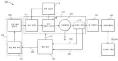
도 1a는 실시예에 따라 배기장치에 결합된 플라즈마 세정 모듈을 포함하는 프로세싱 도구의 단면도 예시이다.
도 1b는 실시예에 따라 모듈식 마이크로파 플라즈마 소스 및 배기장치에 결합된 플라즈마 세정 모듈을 포함하는 프로세싱 도구의 단면도 예시이다.
도 2는 실시예에 따라 마이크로파 전자기 방사선을 생성하기 위한 솔리드 스테이트 일렉트로닉스의 블록도이다.
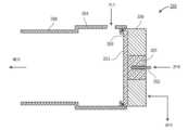
도 3a는 실시예에 따른 플라즈마 세정 모듈의 단면도 예시이다.
도 3b는 실시예에 따라 모놀리식(monolithic) 구조인 유전체 플레이트 및 유전체 공진기를 갖는 플라즈마 세정 모듈의 단면도 예시이다.
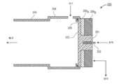
도 3c는 실시예에 따라, 다수의 층들을 포함하는 유전체 공진기를 둘러싸는 전도성 층을 갖는 플라즈마 세정 모듈의 단면도 예시이다.
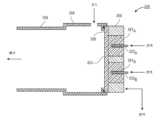
도 3d는 실시예에 따라 복수의 유전체 공진기들을 갖는 플라즈마 세정 모듈의 단면도 예시이다.
도 4a는 실시예에 따라 집적 플라즈마 세정 모듈을 갖는 배기장치의 단면도 예시이다.
도 4b는 실시예에 따라 포터블(portable) 플라즈마 세정 모듈을 갖는 배기장치의 단면도 예시이다.
도 5a는 실시예에 따른 이동식 세정 조립체의 블록도이다.
도 5b는 추가적인 실시예에 따른 이동식 세정 조립체의 블록도이다.
도 6은 실시예에 따라 배기 라인을 세정하기 위해 세정 모듈을 사용하기 위한 프로세스의 프로세스 흐름도이다.
도 7은 실시예에 따라 플라즈마 세정 모듈과 함께 사용될 수 있는 예시적인 컴퓨터 시스템의 블록도를 예시한다.1A is a cross-sectional illustration of a processing tool that includes a plasma cleaning module coupled to an exhaust system according to an embodiment.
1B is a cross-sectional illustration of a processing tool that includes a plasma cleaning module coupled to a modular microwave plasma source and exhaust in accordance with an embodiment.
2 is a block diagram of solid state electronics for generating microwave electromagnetic radiation according to an embodiment.
3A is a cross-sectional illustration of a plasma cleaning module according to an embodiment.
3B is a cross-sectional illustration of a plasma cleaning module having a monolithic structure dielectric plate and a dielectric resonator according to an embodiment.
3C is a cross-sectional illustration of a plasma cleaning module having a conductive layer surrounding a dielectric resonator comprising multiple layers, according to an embodiment.
3D is a cross-sectional illustration of a plasma cleaning module having a plurality of dielectric resonators according to an embodiment.
4A is a cross-sectional illustration of an exhaust system having an integrated plasma cleaning module according to an embodiment.
4B is a cross-sectional illustration of an exhaust system having a portable plasma cleaning module according to an embodiment.
5A is a block diagram of a mobile cleaning assembly according to an embodiment.
5B is a block diagram of a mobile cleaning assembly according to a further embodiment.
6 is a process flow diagram of a process for using a cleaning module to clean an exhaust line according to an embodiment.
7 illustrates a block diagram of an example computer system that can be used with a plasma cleaning module according to an embodiment.
본 명세서에 설명된 실시예들에 따른 디바이스(device)들은 챔버 배기 라인을 위한 세정 유닛을 포함한다. 이하의 설명에서, 실시예들의 완전한 이해를 제공하기 위해 다수의 특정 세부사항들이 제시된다. 실시예들이 이들 특정 세부사항들 없이 실시될 수 있다는 것은 당업자에게 명백할 것이다. 다른 경우들에서, 실시예들을 불필요하게 모호하게 하지 않기 위해 잘 알려진 양태들은 상세하게 설명되지 않는다. 또한, 첨부된 도면들에 도시된 다양한 실시예들은 예시적인 표현들이고, 반드시 실척대로 그려지지 않는다는 것을 이해해야 한다.Devices according to the embodiments described herein include a cleaning unit for a chamber exhaust line. In the following description, numerous specific details are set forth in order to provide a thorough understanding of the embodiments. It will be apparent to one skilled in the art that embodiments may be practiced without these specific details. In other instances, well-known aspects have not been described in detail in order not to unnecessarily obscure the embodiments. Also, it should be understood that the various embodiments shown in the accompanying drawings are illustrative representations and are not necessarily drawn to scale.
위에서 언급한 바와 같이, 배기 라인에 침전물들이 축적되면 프로세싱 도구에 비용이 많이 드는 가동 중지 시간이 필요하다. 따라서, 본 명세서에 개시된 실시예들은 배기 라인에 부착된 플라즈마 세정 모듈을 포함한다. 플라즈마 세정 모듈은 배기 라인을 세정하는 플라즈마 종을 제공할 수 있다. 따라서 플라즈마 세정 모듈은 상당한 양의 시간 동안 프로세싱 도구를 오프라인(off-line) 상태로 둘 필요 없이 침전물들을 제거할 수 있다. 특히, 프로세싱 도구는 세정하는 동안 진공 하에 유지될 수 있으므로, 유지보수 후에 프로세싱 도구를 다시 진공 배기(re-evacuate)시키고 기판 프로세싱을 위한 안정한 조건들을 재-확립할 필요가 없다. 이것은 상당한 비용 절감들이다.As mentioned above, the buildup of deposits in the exhaust line can result in costly downtime for the processing tool. Accordingly, embodiments disclosed herein include a plasma cleaning module attached to an exhaust line. The plasma cleaning module can provide a plasma species that cleans the exhaust line. Thus, the plasma cleaning module can remove deposits without having to take the processing tool off-line for a significant amount of time. In particular, since the processing tool can be held under vacuum during cleaning, there is no need to re-evacuate the processing tool and re-establish stable conditions for substrate processing after maintenance. These are significant cost savings.
일부 실시예들에서, 플라즈마 세정 모듈은 포터블이다. 즉, 플라즈마 세정 모듈은 다수의 챔버들 사이에서 공유될 수 있는 이동식 세정 조립체의 일부일 수 있다. 이는 세정 기능성을 제공하는 데 필요한 자본 비용들을 감소시키다. 추가로, 프로세싱 도구들은 플라즈마 세정 모듈을 수용하기 위해 충분한 재설계를 필요로 하지 않을 수 있다. 플라즈마 세정 모듈은 배기 라인을 따라 포트(port)에 연결될 수 있다.In some embodiments, the plasma cleaning module is portable. That is, the plasma cleaning module can be part of a mobile cleaning assembly that can be shared among multiple chambers. This reduces the capital costs required to provide cleaning functionality. Additionally, processing tools may not require significant redesign to accommodate the plasma cleaning module. The plasma cleaning module may be connected to a port along an exhaust line.
플라즈마 소스의 설계로 인해 포터블 플라즈마 세정 모듈이 가능하다. 특히, 본 명세서에 개시된 실시예들은 솔리드 스테이트 일렉트로닉스를 갖는 마이크로파 플라즈마 소스를 포함한다. 이러한 마이크로파 소스를 사용하면 체적이 큰 도파관을 필요로 하는 마그네트론(magnetron) 마이크로파 전력 소스들에 비해 콤팩트 (compact)한 설계가 가능하다. 본 명세서에 개시된 실시예들에서, 솔리드 스테이트 일렉트로닉스 모듈은 카트 상에 저장될 수 있고, 동축 케이블(cable)에 의해 포터블 세정 모듈의 유전체 공진기에 부착될 수 있다. 실시예에서, 카트는 포터블 세정 모듈에 또한 부착되는 가스 패널(panel) 및 냉각 소스를 또한 수용할 수 있다. 그러나 가스 및 냉각 유체 중 하나 또는 둘 모두는 또한 일부 실시예들에서 프로세싱 도구로부터 소싱(source)될 수도 있다.Due to the design of the plasma source, a portable plasma cleaning module is possible. In particular, embodiments disclosed herein include a microwave plasma source having solid state electronics. The use of such a microwave source allows for a compact design compared to magnetron microwave power sources that require bulky waveguides. In the embodiments disclosed herein, the solid state electronics module can be stored on a cart and attached to the dielectric resonator of the portable cleaning module by a coaxial cable. In an embodiment, the cart may also contain a gas panel and cooling source that are also attached to the portable cleaning module. However, one or both of the gas and cooling fluid may also be sourced from the processing tool in some embodiments.
추가로, 플라즈마 세정 모듈의 콤팩트한 설계로 인해, 플라즈마 세정 모듈은 프로세싱 도구와 통합될 수 있다. 즉, 플라즈마 세정 모듈은 프로세싱 도구의 일부로 간주될 수 있다. 이러한 실시예들에서, 가스 및 냉각 유체는 프로세싱 도구로부터 소싱될 수 있다.Additionally, due to the compact design of the plasma cleaning module, the plasma cleaning module can be integrated with the processing tool. That is, the plasma cleaning module can be considered part of the processing tool. In these embodiments, gas and cooling fluid may be sourced from the processing tool.
이제 도 1을 참조하면, 실시예에 따라, 플라즈마 세정 모듈(150)을 포함하는 프로세싱 도구(100)의 단면도 예시가 도시되어 있다. 플라즈마 프로세싱 도구(100)는 플라즈마 에칭 챔버, 화학 기상 증착 챔버, 플라즈마 강화 화학 기상 증착 챔버, 원자층 증착 챔버, 플라즈마 강화 원자층 증착 챔버, 물리 기상 증착 챔버, 플라즈마 처리 챔버, 이온 주입 챔버, 또는 다른 적합한 진공 또는 제어된 환경 프로세싱 챔버일 수 있다.Referring now to FIG. 1 , a cross-sectional illustration of a
프로세싱 도구(100)는 접지된 챔버(142)를 포함한다. 챔버(142)는 프로세싱 구역(102) 및 진공 배기 구역(104)을 포함할 수 있다. 챔버(142)는 리드 조립체(110)로 밀봉될 수 있다. 프로세스 가스들은 하나 이상의 가스 소스들(106)(예를 들어, 가스 패널)로부터 질량 흐름 제어기(149)를 통해 리드 조립체(110)로 그리고 프로세싱 구역(102) 내로 공급된다.The
배기 구역(196)의 펌프는 챔버(142) 내의 원하는 압력을 유지하고, 챔버(142)에서의 프로세싱으로부터의 부산물들을 제거할 수 있다. 실시예에서, 배기 구역은 챔버(142)와 펌프 사이에 있는 배기 라인(155)을 포함할 수 있다. 세정 라인(156)은 배기 라인(155)과 교차할 수 있다. 실시예에서, 세정 라인(156)은 배기 라인(155)과 플라즈마 세정 모듈(150) 사이에 있다. 실시예에서, 플라즈마 세정 모듈은 배기 구역(196)을 세정하기 위한 원격 플라즈마를 제공하도록 구성된다.A pump in the
실시예에서, 플라즈마 세정 모듈(150)은 세정 챔버(154)를 포함한다. 세정 챔버(154)는 플라즈마가 생성되는 곳이다. 실시예에서, 세정 챔버(154)는 유전체 플레이트(153)에 의해 밀봉되는 제1 개구, 및 세정 라인(156)에 연결되는 제2 개구를 포함한다. 플라즈마 세정 모듈(150)의 플라즈마는 모듈식 마이크로파 소스를 사용하여 생성될 수 있다. 예를 들어, 유전체 공진기(151)는 유전체 플레이트(153)에 결합된다. 유전체 공진기(151)의 축방향 중심 내로 모노폴 안테나(152)가 삽입된다. 모노폴 안테나(152)는 솔리드 스테이트 마이크로파 생성 일렉트로닉스에 연결된다(아래에서 더 자세히 설명됨). 솔리드 스테이트 설계로 인해, 마그네트론 스타일(style) 마이크로파 플라즈마에 필요한 체적이 큰 도파관들 및 다른 컴포넌트들이 필요하지 않으며, 콤팩트한 설계가 제공된다. 콤팩트한 설계는 플라즈마 세정 모듈(150)이 상당한 재설계 없이 프로세싱 도구와 통합될 수 있게 한다.In an embodiment, the
실시예에서, 플라즈마 세정 모듈(150)은 가스 라인(158)에 의해 가스 소스(106)에 연결된다. 질량 흐름 제어기(159)는 세정 챔버(154) 내로의 가스의 흐름을 제어할 수 있다. 예시된 실시예에서, 가스 라인(158)은 세정 챔버(154)의 벽을 통과하는 것으로 도시되어 있다. 그러나 가스는 또한 (예를 들어, 샤워헤드(showerhead) 설계 또는 다른 매니폴드(manifold) 유형 구조를 사용하여) 유전체 플레이트(153)를 통해 공급될 수 있음을 이해해야 한다. 실시예에서, 플라즈마 세정 모듈(150)은 또한 온도 제어될 수 있다. 예를 들어, 플라즈마 세정 모듈(150)은 냉각 유체의 소스에 연결될 수 있다.In an embodiment, the
실시예에서, 리드 조립체(110)는 일반적으로 샤워헤드 플레이트(116) 및 열전달 플레이트(118)를 포함하는 상부 전극을 포함한다. 리드 조립체(110)는 절연 층(113)에 의해 챔버(142)로부터 격리된다. 상부 전극은 매치(match)(도시되지 않음)를 통해 소스 RF 생성기(103)에 결합된다. 소스 RF 생성기(103)는 예를 들어 300 kHz 내지 60 MHz 또는 60 MHz 내지 180 MHz의 주파수를 가질 수 있고, 특정 실시예에서는, 13.56 MHz 대역에 있다.In an embodiment, the
따라서, 프로세싱 도구(100)는 한 쌍의 플라즈마 소스들을 포함할 수 있다. 예를 들어, RF 생성기(103)는 프로세싱 구역(102)에서 제1 플라즈마를 생성할 수 있고, 마이크로파 일렉트로닉스는 세정 챔버(154)에서 제2 플라즈마를 생성할 수 있다. 도 1a에 예시된 특정 실시예에서, 제1 플라즈마 및 제2 플라즈마는 상이한 파장들의 전자기 방사선으로 생성된다.Accordingly, the
가스 소스(106)로부터의 가스는 샤워헤드 플레이트(116) 내의 매니폴드(120) 내로 들어가고, 샤워헤드 플레이트(116) 내로의 개구들을 통해 챔버(142)의 프로세싱 구역(102) 내로 빠져나간다. 실시예에서, 열전달 플레이트(118)는 열전달 유체가 흐르는 채널들(119)을 포함한다. 샤워헤드 플레이트(116) 및 열전달 플레이트(118)는 알루미늄 또는 스테인리스강과 같은 RF 전도성 재료로 제조된다. 특정 실시예들에서, 샤워헤드 플레이트(116) 대신에(또는 이에 추가로) 챔버(142) 내로 프로세싱 가스들을 분배하기 위해 가스 노즐 또는 다른 적절한 가스 분배 조립체가 제공된다.Gas from the
프로세싱 구역(102)은 기판(105)이 고정되는 하부 전극(161)을 포함할 수 있다. 기판(105)을 둘러싸는 프로세스 링(ring)(197)의 부분들이 또한 하부 전극(161)에 의해 지지될 수 있다. 기판(105)은 챔버(142)를 통한 슬릿 밸브 터널(slit valve tunnel)(141)을 통해 챔버(142) 내로 삽입(또는 그로부터 추출)될 수 있다. 슬릿 밸브 터널(141)을 위한 도어(door)는 단순화를 위해 생략된다. 하부 전극(161)은 정전기 척(chuck)일 수 있다. 하부 전극(161)은 지지 부재(157)에 의해 지지될 수 있다. 실시예에서, 하부 전극(161)은 복수의 가열 존(zone)들을 포함할 수 있으며, 각각의 존은 온도 설정점으로 독립적으로 제어될 수 있다. 예를 들어, 하부 전극(161)은 기판(105)의 중심에 근접한 제1 열 존 및 기판(105)의 주변부에 근접한 제2 열 존을 포함할 수 있다. 바이어스(bias) 전력 RF 생성기(125)는 매치(127)를 통해 하부 전극(161)에 결합된다. 바이어스 전력 RF 생성기(125)는, 원한다면, 플라즈마에 에너지를 공급하기 위해 바이어스 전력을 제공한다. 바이어스 전력 RF 생성기(125)는 예를 들어 약 300 kHz 내지 60 MHz의 낮은 주파수를 가질 수 있고, 특정 실시예에서는, 13.56 MHz 대역에 있다.The
도 1a에서, 프로세싱 도구(100)는 프로세싱 구역(102)에서 플라즈마를 형성할 수 있는 플라즈마 반응기인 것으로 도시된다. 그러나 프로세싱 도구(100)는 플라즈마 소스를 이용하지 않는 프로세싱 구역(102)을 포함할 수 있다는 것이 이해되어야 한다. 예를 들어, 프로세싱 도구(100)는 퍼니스(furnace)를 포함할 수 있다. 일부 실시예들에서, 프로세싱 구역(102)은 또한 뱃치(batch) 반응기일 수 있다. 즉, 프로세싱 구역(102)은 동시에 복수의 기판들을 프로세싱할 수 있다.In FIG. 1A ,
이제 도 1b를 참조하면, 추가적인 실시예에 따른 프로세싱 도구(100)의 단면도 예시가 도시되어 있다. 도 1b의 프로세싱 도구는, 프로세싱 구역(102)에서 플라즈마를 생성하기 위한 플라즈마 소스(130)를 제외하고, 도 1a의 프로세싱 도구(100)와 실질적으로 유사할 수 있다. RF 플라즈마 소스를 사용하는 대신에, 도 1b의 프로세싱 도구(100)는 마이크로파 플라즈마 소스(130)를 사용할 수 있다. 특정 실시예에서, 마이크로파 플라즈마 소스(130)는 모듈식 마이크로파 플라즈마 소스이다. 예를 들어, 마이크로파 플라즈마 소스(130)는 유전체 플레이트(133) 위에 배열된 복수의 유전체 공진기들(131)을 갖는 유전체 플레이트(133)를 포함할 수 있다. 각각의 유전체 공진기(131)의 축방향 중심에는 모노폴 안테나(131)가 배치될 수 있다. 모노폴 안테나(131)는 솔리드 스테이트 마이크로파 생성 일렉트로닉스에 각각 연결될 수 있다.Referring now to FIG. 1B , a cross-sectional illustration of a
일 실시예에서, 마이크로파 플라즈마 소스(130)의 솔리드 스테이트 마이크로파 일렉트로닉스는 플라즈마 세정 모듈(150)에서 플라즈마 생성에 사용되는 동일한 마이크로파 일렉트로닉스일 수 있다. 다른 실시예들에서, 마이크로파 플라즈마 소스(130) 및 플라즈마 세정 모듈(150)을 위해 별도의 마이크로파 일렉트로닉스가 사용될 수 있다.In one embodiment, the solid state microwave electronics of the
이제 도 2를 참조하면, 실시예에 따른 솔리드 스테이트 전력 소스(215)의 개략도가 도시되어 있다. 실시예에서, 솔리드 스테이트 전력 소스(215)는 발진기 모듈(206)을 포함한다. 발진기 모듈(206)은 원하는 주파수에서 마이크로파 전자기 방사선을 생성하기 위해 전압 제어 발진기(220)에 입력 전압을 제공하기 위한 전압 제어 회로(211)를 포함할 수 있다. 실시예들은 대략 1 V 내지 10 V DC의 입력 전압을 포함할 수 있다. 전압 제어 발진기(220)는 입력 전압에 의해 발진 주파수가 제어되는 전자 발진기이다. 실시예에 따르면, 전압 제어 회로(211)로부터의 입력 전압은 전압 제어 발진기(220)가 원하는 주파수에서 발진하게 한다. 실시예에서, 마이크로파 전자기 방사선은 대략 0.1 MHz 내지 30 MHz의 주파수를 가질 수 있다. 실시예에서, 마이크로파 전자기 방사선은 대략 30 MHz 내지 300 MHz의 주파수를 가질 수 있다. 실시예에서, 마이크로파 전자기 방사선은 대략 300 MHz 내지 1 GHz의 주파수를 가질 수 있다. 실시예에서, 마이크로파 전자기 방사선은 대략 1 GHz 내지 300 GHz의 주파수를 가질 수 있다.Referring now to FIG. 2 , a schematic diagram of a solid
실시예에 따르면, 전자기 방사선은 전압 제어 발진기(220)로부터 증폭 모듈(212)로 전달된다. 증폭 모듈(212)은, 각각 전력 공급기(216)에 결합되는, 드라이버(driver)/전치 증폭기(213) 및 메인 전력 증폭기(214)를 포함할 수 있다. 실시예에 따르면, 증폭 모듈(212)은 펄스 모드(pulse mode)로 동작할 수 있다. 예를 들어, 증폭 모듈(212)은 1 % 내지 99 %의 듀티 사이클(duty cycle)을 가질 수 있다. 보다 특정한 실시예에서, 증폭 모듈(212)은 대략 15 % 내지 50 %의 듀티 사이클을 가질 수 있다.According to an embodiment, electromagnetic radiation is passed from the voltage controlled
실시예에서, 전자기 방사선은 증폭 모듈(212)에 의해 프로세싱된 후에 열 브레이크(break)(219) 및 어플리케이터(applicator)(231)로 전달될 수 있다. 그러나 열 브레이크(219)로 전달된 전력의 일부는 출력 임피던스(impedance)의 불일치로 인해 역반사될 수 있다. 따라서, 일부 실시예들은 접지에 반사 전력을 라우팅(route)하는 서큘레이터(circulator)(217)에 반사 전력이 도달하기 전에 순방향 전력(204) 및 반사 전력(203)의 레벨(level)이 감지되어 제어 회로 모듈(208)로 피드백(feed back)되도록 허용하는 검출기 모듈(218)을 포함한다. 검출기 모듈(218)은 시스템 내의 하나 이상의 상이한 로케이션(location)들에 로케이팅(locate)될 수 있음을 이해해야 한다. 실시예에서, 제어 회로 모듈(208)은 순방향 전력(204) 및 반사 전력(203)을 해석하고, 발진기 모듈(206)에 통신 가능하게 결합된 제어 신호(209)에 대한 레벨 및 증폭기 모듈(212)에 통신 가능하게 결합된 제어 신호(207)에 대한 레벨을 결정한다. 실시예에서, 제어 신호(209)는 발진기 모듈(206)을 조정하여 증폭 모듈(212)에 결합된 고주파 방사선을 최적화한다. 실시예에서, 제어 신호(207)는 증폭기 모듈(212)을 조정하여 열 브레이크(219)를 통해 어플리케이터(231)에 결합된 출력 전력을 최적화한다. 실시예에서, 발진기 모듈(206) 및 증폭 모듈(212)의 피드백 제어는, 열 브레이크(219)에서 임피던스 매칭의 테일러링(tailoring)에 추가하여, 반사 전력의 레벨이 순방향 전력의 대략 5 % 미만이 되도록 허용할 수 있다. 일부 실시예들에서, 발진기 모듈(206) 및 증폭 모듈(212)의 피드백 제어는 반사 전력의 레벨이 순방향 전력의 대략 2 % 미만이 되도록 허용할 수 있다.In an embodiment, electromagnetic radiation may be processed by
따라서, 실시예들은 프로세싱 챔버(242) 또는 세정 챔버(254)에 결합되는 순방향 전력의 증가된 백분율을 허용하고, 플라즈마에 결합되는 가용 전력을 증가시킨다. 또한, 피드백 제어를 사용하는 임피던스 튜닝(tuning)은 일반적인 슬롯 플레이트 안테나들의 임피던스 튜닝보다 우수하다. 슬롯 플레이트 안테나들에서, 임피던스 튜닝은 어플리케이터에 형성된 2 개의 유전체 슬러그(slug)들을 이동하는 것을 수반한다. 이는 어플리케이터의 2 개의 별도의 컴포넌트들의 기계적 모션(motion)을 수반하며, 이는 어플리케이터의 복잡성을 증가시킨다. 또한, 기계적 모션은 전압 제어 발진기(220)에 의해 제공될 수 있는 주파수의 변화만큼 정확하지 않을 수 있다.Thus, embodiments allow an increased percentage of forward power to be coupled to processing chamber 242 or clean chamber 254 and increase available power coupled to the plasma. Also, impedance tuning using feedback control is superior to impedance tuning of typical slot plate antennas. In slot plate antennas, impedance tuning involves moving two dielectric slugs formed in the applicator. This involves mechanical motion of two separate components of the applicator, which increases the complexity of the applicator. Also, the mechanical motion may not be as precise as the change in frequency that can be provided by the voltage controlled
이제 도 3a 내지 도 3d를 참조하면, 다양한 실시예들에 따른 다양한 플라즈마 세정 모듈들(350)의 단면도 예시들이 도시되어 있다. 도 3a 내지 도 3d의 플라즈마 세정 모듈들(350)은 프로세싱 도구와 통합될 수 있다. 다른 실시예들에서, 플라즈마 세정 모듈들(350)은 포터블 플라즈마 세정 모듈들일 수 있다. 즉, 플라즈마 세정 모듈들(350)은 프로세싱 도구로부터 쉽게 분리될 수 있다. 포터블 플라즈마 세정 모듈들은 아래에서 자세히 설명된다.Referring now to FIGS. 3A-3D , cross-sectional illustrations of various
이제 도 3a를 참조하면, 실시예에 따른 플라즈마 세정 모듈(350)의 단면도 예시가 도시되어 있다. 플라즈마 세정 모듈(350)은 플라즈마가 생성되는 세정 챔버(354)를 포함할 수 있다. 세정 챔버(354)는 제1 개구 및 제2 개구를 가질 수 있다. 제1 개구는 유전체 플레이트(353)에 의해 폐쇄될 수 있다. 실시예에서, 시일(seal)(358)(예를 들어, O-링 등)이 유전체 플레이트(353)와 세정 챔버(354) 사이에 포지셔닝될 수 있다. 제2 개구는 세정 라인(356)에 유체 결합될 수 있다. 세정 라인은 프로세싱 도구(도시되지 않음)의 배기 라인에 결합된다.Referring now to FIG. 3A , a cross-sectional illustration of a
실시예에서, 유전체 공진기(351)는 유전체 플레이트(353)에 결합된다. 유전체 공진기(351)의 축방향 중심에는 구멍이 배치될 수 있다. 실시예에서, 모노폴 안테나(352)가 구멍 내로 삽입된다. 모노폴 안테나(352)는 마이크로파 전자기 방사선을 공급하는 전력 소스에 연결된다. 예를 들어, 전력 소스는 도 2와 관련하여 위에서 설명된 솔리드 스테이트 전력 소스(215)와 같은 솔리드 스테이트 마이크로파 일렉트로닉스 모듈일 수 있다. 예시된 실시예에서, 유전체 공진기(351)는 유전체 플레이트(353)의 외부 표면에 맞대어 있다(against). 그러나 다른 실시예들에서, 유전체 공진기(351)는 유전체 플레이트를 통해 연장될 수 있고, 세정 챔버(354) 내의 자유 공간 내로 연장될 수 있다.In an embodiment,
실시예에서, 전도성 층(359)은 유전체 공진기(351)를 둘러쌀 수 있다. 전도성 층(359)은 일부 실시예들에서 접지 전위로 유지될 수 있다. 전도성 층(359)은 유전체 공진기(351)를 차폐하고, 세정 챔버(354) 내로의 마이크로파 전자기 방사선의 개선된 결합을 제공한다. 실시예에서, 전도성 층(359)은 온도 제어 컴포넌트일 수 있다. 예를 들어, 전도성 층은 냉각제 소스에 유체 결합될 수 있다. 전도성 층(359)은 냉각제 소스로부터의 냉각제가 흐르는 냉각 채널들(도시되지 않음)을 포함할 수 있다. 다른 실시예들에서, 플라즈마 세정 모듈은 또한 가열 요소를 포함하거나 또는 고온 열 유체의 소스에 결합될 수 있다.In an embodiment,
실시예에서, 가스는 세정 챔버(354)에 공급될 수 있다. 가스는 세정 챔버(354)의 벽에 있는 포트를 통해 주입될 수 있다. 다른 실시예들에서, 가스는 유전체 플레이트(353)을 통해 세정 챔버(354)로 공급될 수 있다.In an embodiment, a gas may be supplied to the
이제 도 3b를 참조하면, 추가적인 실시예에 따른 플라즈마 세정 모듈(350)의 단면도 예시가 도시되어 있다. 도 3b의 플라즈마 세정 모듈(350)은, 유전체 플레이트(353)와 유전체 공진기(351) 사이의 인터페이스(interface)를 제외하고, 도 3a의 플라즈마 세정 모듈(350)과 실질적으로 유사할 수 있다. 예를 들어, 도 3b에 도시된 실시예에서 유전체 플레이트(353)와 유전체 공진기(351) 사이에 식별 가능한 인터페이스가 없을 수 있다. 즉, 유전체 플레이트(353) 및 유전체 공진기(351)는 단일의 모놀리식 구조로 형성될 수 있다.Referring now to FIG. 3B , a cross-sectional illustration of a
이제 도 3c를 참조하면, 추가적인 실시예에 따른 플라즈마 세정 모듈(350)의 단면도 예시가 도시되어 있다. 도 3c의 플라즈마 세정 모듈(350)은, 전도성 층(359)의 구성을 제외하고, 도 3b의 플라즈마 세정 모듈(350)과 실질적으로 유사할 수 있다. 도시된 바와 같이, 전도성 층(359)은 복수의 전도성 층들을 포함할 수 있다. 예를 들어, 제1 전도성 층(359A)은 유전체 플레이트(353) 위에 있고, 제2 전도성 층(359B)은 제1 전도성 층 위에 있다. 유사한 다중-층 전도성 층(359)이 도 3a에 도시된 구성과 유사한 구성으로 구현될 수 있다. 즉, 제1 전도성 층(359A) 및 제2 전도성 층(359B)은 유전체 플레이트(353) 및 유전체 공진기(351)가 별개의 컴포넌트들인 경우에 구현될 수 있다.Referring now to FIG. 3C , a cross-sectional illustration of a
실시예에서, 제1 전도성 층(359A)은 제1 열팽창 계수(CTE)를 가질 수 있고, 제2 전도성 층(359B)은 제1 CTE보다 큰 제2 CTE를 가질 수 있다. 특히, 제1 전도성 층(359A)의 제1 CTE는 그렇지 않은 경우 유전체 플레이트(353)에 손상을 줄 수 있는 열 응력을 최소화하기 위해 유전체 플레이트(353)의 CTE에 근접하게 매칭될 수 있다. 특정 실시예에서, 제1 전도성 층(359A)은 티타늄을 포함할 수 있고, 제2 전도성 층(359B)은 알루미늄을 포함할 수 있다. 일부 실시예들에서, 제1 전도성 층(359A)은 제2 전도성 층(359B)에 고정될 수 있다. 예를 들어, 제1 전도성 층(359A)은 제2 전도성 층(359B)에 볼트 결합되거나 또는 다른 방식으로 본딩(bond)될 수 있다.In an embodiment, the first
이제 도 3d를 참조하면, 추가적인 실시예에 따른 플라즈마 세정 모듈(350)의 단면도 예시가 도시되어 있다. 도 3d의 플라즈마 세정 모듈(350)은, 복수의 유전체 공진기들(351)이 유전체 플레이트(353) 위에 배치된다는 점을 제외하면, 도 3a의 플라즈마 세정 모듈(350)과 실질적으로 유사할 수 있다. 2 개의 유전체 공진기들(351A 및 351B)이 도시되어 있지만, 임의의 개수의 유전체 공진기들(351)이 플라즈마 세정 모듈(350)에 포함될 수 있음을 이해해야 한다. 유전체 공진기들(351)의 개수를 증가시키면 배기 구역의 개선된 세정을 제공할 수 있다.Referring now to FIG. 3D , a cross-sectional illustration of a
이제 도 4a를 참조하면, 실시예에 따른 배기 구역(496)의 단면도 예시가 도시되어 있다. 도 4a의 배기 구역(496)은 통합 플라즈마 세정 모듈(450)을 예시한다. 즉, 플라즈마 세정 모듈(450)은 프로세싱 도구의 일부로서 통합된다. 실시예에서, 배기 구역(496)은 메인 프로세싱 챔버(442)를 펌프에 유체 결합하는 배기 라인(455)을 포함한다. 실시예에서, 스로틀 밸브(484)는 배기 라인(455) 내에 배치될 수 있다. 세정 라인(456)은 플라즈마 세정 모듈(450)의 세정 챔버(454)를 배기 라인(455)에 유체 결합한다.Referring now to FIG. 4A , a cross-sectional illustration of an
실시예에서, 플라즈마 세정 모듈(450)은 위에서 설명된 플라즈마 세정 모듈들(350) 중 임의의 플라즈마 세정 모듈과 실질적으로 유사할 수 있다. 예를 들어, 플라즈마 세정 모듈(450)은 세정 챔버(454), 유전체 플레이트(453), 유전체 공진기(451), 모노폴 안테나(452), 및 전도성 층(459)을 포함할 수 있다.In an embodiment, the
실시예에서, 배기 구역(496)은 복수의 밸브들을 포함할 수 있다. 제1 밸브(481)는 메인 챔버(442)와 스로틀 밸브(484) 사이에서 배기 라인(455)을 따라 포지셔닝될 수 있다. 제1 밸브(481)는 세정 동안 챔버(443)를 격리하기 위해 폐쇄될 수 있다. 이와 같이, 메인 챔버(442)의 조건은 유지보수 중에 또는 유지보수 후에 변경되지 않는다. 스로틀 밸브(482)와 펌프 사이에서 배기 라인(455)을 따라 제2 밸브(482)가 포지셔닝될 수 있다. 제3 밸브(483)는 세정 챔버(454)와 배기 라인(455) 사이에서 세정 라인(456)을 따라 포지셔닝될 수 있다. 밸브들(481, 482, 483)은 프로세싱 도구 컴퓨터(도시되지 않음)에 의해 제어될 수 있다.In an embodiment, the
실시예에서, 밸브들(481, 482, 483)은 원하는 프로세싱 동작에 따라 개방되거나 또는 폐쇄될 수 있다. 예를 들어, 메인 챔버(442)에서 기판들을 프로세싱하는 동안, 제1 밸브(481) 및 제2 밸브(482)는 개방될 수 있고, 제3 밸브(483)는 폐쇄될 수 있다. 세정 동작 동안, 제3 밸브(483)는 개방되고, 제1 밸브(481)는 폐쇄될 수 있다. 플라즈마 세정 모듈(450)을 사용하여 세정 동작을 구현하기 위한 프로세스는 도 6과 관련하여 아래에서 더 자세히 설명된다.In an embodiment,
이제 도 4b를 참조하면, 추가적인 실시예에 따른 프로세싱 도구의 배기 구역(496)의 단면도 예시가 도시되어 있다. 실시예에서, 도 4b의 배기 구역(496)은, 플라즈마 세정 모듈(450)이 포터블 플라즈마 세정 모듈(450)이라는 점을 제외하면, 도 4a의 배기 구역(496)과 실질적으로 유사할 수 있다. 즉, 플라즈마 세정 모듈(450)은 프로세싱 도구에 용이하게 부착되고 이로부터 분리될 수 있도록 구성된다. 실시예에서, 포터블 플라즈마 세정 모듈은 사용되지 않을 때 카트(아래에서 더 자세히 설명됨) 상에 저장될 수 있다.Referring now to FIG. 4B , a cross-sectional illustration of an
실시예에서, 플라즈마 세정 모듈(450)은 세정 챔버(454)에 부착되는 플랜지(flange)(485)를 포함할 수 있다. 세정 라인(456)은 또한 플라즈마 세정 모듈(450)의 플랜지(485)와 인터페이싱하기 위한 플랜지(486)를 포함할 수 있다. 세정 라인(456)과 플라즈마 세정 모듈(450) 사이에 진공 타이트(tight) 시일을 제공하기에 적합한 임의의 적합한 플랜지들 또는 다른 연결 방식들이 사용될 수 있다. 예를 들어, 플랜지들(485, 486)은 KF40 또는 KF50 플랜지들을 포함할 수 있다.In an embodiment, the
이제 도 5a 및 도 5b를 참조하면, 실시예에 따른 이동식 세정 조립체들(560)의 개략도들이 도시되어 있다. 이동식 세정 조립체들(560)은 복수의 프로세싱 도구들에 세정을 제공하기 위해 시설 전체에 걸쳐 포터블 플라즈마 세정 모듈(550)의 용이한 이동을 허용한다. 일부 실시예들에서, 이동식 세정 조립체들(560)은 또한 포터블 플라즈마 세정 모듈(550)을 위한 하나 이상의 주변장치들(예를 들어, 가스, 냉각 유체 등)을 포함할 수 있다.Referring now to FIGS. 5A and 5B , schematic views of
이제 도 5a를 참조하면, 실시예에 따른 이동식 세정 조립체(560)의 개략도가 도시되어 있다. 실시예에서, 이동식 세정 조립체(560)는 카트(561) 및 카트(561)에 부착된 플라즈마 세정 모듈(550)을 포함한다. 실시예에서, 플라즈마 세정 모듈(550)은 본 명세서에 개시된 플라즈마 세정 모듈들 중 임의의 플라즈마 세정 모듈과 유사할 수 있다. 예를 들어, 플라즈마 세정 모듈(550)은 세정 챔버(554), 유전체 플레이트(553), 및 유전체 공진기(551)를 포함할 수 있다. 플라즈마 세정 모듈을 프로세싱 도구에 부착하기 위해 플랜지(585) 또는 다른 인터커넥트(interconnect) 컴포넌트가 세정 챔버(554)에 연결될 수 있다. 카트(561)는 시설 주위로 용이하게 이송된다. 예를 들어, 카트(561)는 휠(wheel)들의 세트(set)(562)를 가질 수 있다.Referring now to FIG. 5A , a schematic diagram of a
사용하지 않을 때, 플라즈마 세정 모듈(550)은 카트(560) 상에 저장된다. 사용될 때, 플라즈마 세정 모듈(550)은 카트(560) 상에 저장된 주변장치들에 대한 다양한 인터커넥트들에 의해 카트(560)에 테더링(tether)될 수 있다. 예를 들어, 카트(560)는 솔리드 스테이트 마이크로파 일렉트로닉스(563), 열전달 유체의 온도 제어 용기(예를 들어, 냉각 유닛(564)), 및 가스 패널(565)을 수용할 수 있다. 플라즈마 세정 모듈(550)과 마이크로파 일렉트로닉스(563) 사이의 라인(568)은 동축 케이블일 수 있다. 가스 라인(571) 및 유체 라인(569)은 각각 가스들 및 유체들을 수송하기 위한 임의의 적합한 라인들일 수 있다.When not in use, the
또 다른 실시예에서, 플라즈마 세정 모듈(550)은 도 4a에 도시된 실시예와 유사하게, 카트(560) 상에 저장되는 대신에 프로세싱 도구와 통합될 수 있다. 이러한 실시예에서, 카트(560) 상에 저장된 주변장치들은 플라즈마 세정 모듈(550)이 사용되지 않을 때 플라즈마 세정 모듈(550)로부터 분리 가능한 라인들(568, 569, 571)에 의해 플라즈마 세정 모듈(550)에 부착될 수 있다.In another embodiment, the
실시예에서, 프로세서(예를 들어, CPU)(566)가 또한 카트(561) 상에 제공된다. 프로세서(566)는 카트(561) 상의 주변장치들에 통신 가능하게 결합될 수 있다. 이와 같이, 프로세서(566)는 (즉, 마이크로파 일렉트로닉스(563)의 제어를 통해) 플라즈마 세정 모듈(550)을 제어하고, 그뿐만 아니라 (즉, 냉각 유닛(564)의 제어를 통해) 플라즈마 세정 모듈(550)의 온도를 제어하고 그리고 (즉, 가스 패널(565)의 제어를 통해) 플라즈마 세정 모듈(550)로의 가스 흐름들을 제어하기 위해 사용될 수 있다. 일부 실시예들에서, 프로세서(566)는 또한 프로세싱 도구 CPU(570)에 통신 가능하게 결합될 수 있다. 이와 같이, 프로세싱 도구(도시되지 않음)의 컴포넌트들은 또한 플라즈마 세정 모듈(550)과 함께 작업하도록 제어될 수 있다. 예를 들어, 프로세싱 도구의 배기 구역에 있는 하나 이상의 밸브들은 세정 프로세스를 개시하기 위해 개방되거나 또는 폐쇄될 수 있다.In an embodiment, a processor (eg, CPU) 566 is also provided on
실시예에서, 이동식 세정 조립체(560)를 위한 전력이 플러그(plug)(567)에 의해 제공될 수 있다. 플러그(567)는 120 V 또는 240 V 콘센트(outlet)에 연결되는 표준 플러그일 수 있다. 따라서, 이러한 실시예들에서는 더 높은 전압들을 제공하기 위한 전용 전력 공급기들이 필요하지 않다. 더 낮은 전력 요구 사항들은 마이크로파 전자기 방사선을 세정 챔버(554) 내로 주입하기 위해 사용되는 하나 (또는 여러 개의) 어플리케이터들을 구동하는 콤팩트한 설계 및 솔리드 스테이트 일렉트로닉스에 기인할 수 있다.In an embodiment, power for the
이제 도 5b를 참조하면, 추가적인 실시예에 따른 이동식 세정 조립체(560)의 개략도가 도시되어 있다. 이동식 세정 조립체(560)는, 플라즈마 세정 모듈(550)에 대한 주변장치들 중 하나 이상이 카트(561)로부터 제거된다는 점을 제외하면, 도 5a의 이동식 세정 조립체(560)와 실질적으로 유사할 수 있다. 특히, 도 5b의 실시예는 카트(561)로부터 가스 패널의 제거를 도시한다. 대신에, 플라즈마 세정 모듈(550)에 대한 가스는 프로세싱 도구의 가스 패널(506)로부터 소싱된다.Referring now to FIG. 5B , a schematic diagram of a
도 5b에서, 냉각 유닛(564)은 카트(561) 상에 유지된다. 그러나 냉각 유닛(564)이 또한 카트(561)로부터 제거될 수도 있음을 이해해야 한다. 이러한 실시예들에서, 플라즈마 세정 모듈(550)을 위한 냉각 유체는 프로세싱 도구의 냉각 유닛으로부터 소싱될 수 있다. 일부 실시예들에서, 가스 패널(565) 및 냉각 유닛(564) 둘 모두는 카트(561)로부터 제거될 수 있다.In FIG. 5B , a
다른 실시예들에서, 이동식 세정 조립체(560)는 프로세싱 도구에 연결되기 위한 플라즈마 세정 모듈(550) 및 대응되는 인터커넥트들(예를 들어, 라인(568, 569, 571))만을 포함할 수 있다. 이러한 실시예들에서, 플라즈마 세정 모듈(550)은 프로세싱 도구로부터 전력, 냉각 유체, 및 가스를 소싱할 수 있다. 프로세싱 도구의 프로세서는 또한 플라즈마 세정 모듈(550)의 동작을 제어할 수 있다.In other embodiments, the
이제 도 6을 참조하면, 실시예에 따라 프로세싱 도구의 배기 구역을 세정하기 위한 프로세스(640)를 예시하는 프로세스 흐름도가 도시되어 있다. 프로세스(640)는 통합 플라즈마 세정 모듈 또는 포터블 플라즈마 세정 모듈로 구현될 수 있다. 포터블 플라즈마 세정 모듈의 경우, 프로세스(640)는 또한 포터블 플라즈마 세정 모듈을 배기 라인에 부착하는 단계를 포함할 수 있다.Referring now to FIG. 6 , a process flow diagram illustrating a process 640 for cleaning an exhaust region of a processing tool according to an embodiment is shown. Process 640 may be implemented with an integrated plasma cleaning module or a portable plasma cleaning module. For a portable plasma cleaning module, process 640 may also include attaching the portable plasma cleaning module to an exhaust line.
실시예에서, 프로세스(640)는 배기 라인에서 챔버 밸브를 폐쇄하는 단계를 포함하는 동작(641)을 포함할 수 있다. 폐쇄되는 챔버 밸브는 챔버 격리 밸브일 수 있다. 챔버 격리 밸브는 메인 챔버와 세정 라인 사이에 있는 밸브일 수 있다. 예를 들어, 폐쇄되는 밸브는 도 4a 및 도 4b에 도시된 제1 밸브(481)일 수 있다. 챔버 격리 밸브를 폐쇄하면 메인 챔버의 압력을 변경하지 않고 세정 프로세스가 진행되게 할 수 있다. 따라서, 유지보수 후 추가 펌프 다운이 필요하지 않으며, 프로세싱 도구의 가동 중지 시간이 감소된다.In an embodiment, process 640 may include an
실시예에서, 프로세스(640)는 플라즈마 세정 모듈을 펌프에 유체 결합하기 위해 밸브를 개방하는 단계를 포함하는 동작(462)을 포함할 수 있다. 예를 들어, 개방되는 밸브는 도 4a 및 도 4b의 제3 밸브(483)일 수 있다.In an embodiment, process 640 may include an operation 462 that includes opening a valve to fluidly couple the plasma cleaning module to the pump. For example, the valve to be opened may be the
실시예에서, 프로세스(640)는 펌프로 플라즈마 세정 모듈을 펌핑 다운하는 단계를 포함하는 동작(463)을 포함할 수 있다. 예를 들어, 펌프는 플라즈마 세정 모듈의 세정 챔버에서 플라즈마 생성에 적합한 압력을 생성하도록 활성화될 수 있다.In an embodiment, process 640 may include an operation 463 that includes pumping down the plasma cleaning module with a pump. For example, a pump may be activated to create a pressure suitable for plasma generation in the cleaning chamber of the plasma cleaning module.
세정 챔버에 진공이 제공된 후, 프로세스(640)는 플라즈마 세정 모듈에서 플라즈마를 여기시키는 단계를 포함하는 동작(646)을 포함할 수 있다. 실시예에서, 플라즈마는 원격 플라즈마로 지칭될 수 있다. 즉, 플라즈마는 세정이 요구되는 로케이션에 원격으로 제공될 수 있다. 예를 들어, 세정 라인 및 플라즈마 세정 모듈에 부착된 배기 라인에서 세정이 이루어질 수 있다. 실시예에서, 세정은 배기 라인에 포함된 스로틀 밸브의 세정을 포함할 수 있다.After a vacuum is applied to the cleaning chamber, process 640 may include an operation 646 that includes exciting a plasma in the plasma cleaning module. In an embodiment, the plasma may be referred to as a remote plasma. That is, plasma can be provided remotely to a location where cleaning is desired. For example, cleaning may occur in a cleaning line and an exhaust line attached to a plasma cleaning module. In an embodiment, cleaning may include cleaning of a throttle valve included in an exhaust line.
이제 도 7을 참조하면, 실시예에 따라 사용될 수 있는 프로세싱 도구 또는 이동식 플라즈마 세정 모듈의 예시적인 컴퓨터 시스템(760)의 블록도가 도시되어 있다. 실시예에서, 컴퓨터 시스템(760)은 플라즈마 챔버에 결합되어 플라즈마 챔버에서의 프로세싱을 제어한다. 컴퓨터 시스템(760)은 LAN(Local Area Network), 인트라넷(intranet), 엑스트라넷(extranet), 또는 인터넷(Internet)의 다른 기계들에 연결(예를 들어, 네트워크 연결)될 수 있다. 컴퓨터 시스템(760)은 클라이언트-서버(client-server) 네트워크 환경에서 서버 또는 클라이언트 기계(machine)의 자격으로, 또는 피어-투-피어(peer-to-peer)(또는 분산형) 네트워크 환경에서 피어 기계로서 작동할 수 있다. 컴퓨터 시스템(760)은 개인용 컴퓨터(PC), 태블릿 PC, 셋톱 박스(STB), PDA(Personal Digital Assistant), 셀룰러 전화기, 웹 기기, 서버, 네트워크 라우터(router), 스위치 또는 브리지(bridge), 또는 해당 기계에 의해 수행될 액션들을 지정하는 명령들의 세트를 (순차적으로 또는 다른 방식으로) 실행할 수 있는 임의의 기계일 수 있다. 또한, 컴퓨터 시스템(760)에 대해 단일의 기계만이 예시되어 있지만, "기계"라는 용어는 또한 여기에 설명된 방법론들 중 임의의 하나 이상을 수행하기 위해 명령들의 세트(또는 다수의 세트들)를 개별적으로 또는 공동으로 실행하는 기계들(예를 들어, 컴퓨터들)의 임의의 집합을 포함하는 것으로 간주되어야 한다.Referring now to FIG. 7 , a block diagram of an
컴퓨터 시스템(760)은, 실시예들에 따라 프로세스(550)와 같은 프로세스를 수행하기 위해 컴퓨터 시스템(760)(또는 다른 전자 디바이스들)을 프로그래밍하기 위해 사용될 수 있는 명령들이 저장되어 있는 비-일시적 기계 판독가능 매체를 갖는 컴퓨터 프로그램 제품 또는 소프트웨어(722)를 포함할 수 있다. 기계 판독가능 매체는 기계(예를 들어, 컴퓨터)에 의해 판독 가능한 형태로 정보를 저장하거나 또는 전송하기 위한 임의의 메커니즘을 포함한다. 예를 들어, 기계 판독가능(예를 들어, 컴퓨터 판독가능) 매체는 기계(예를 들어, 컴퓨터) 판독가능 저장 매체(예를 들어, 판독 전용 메모리("ROM"), 랜덤 액세스 메모리("RAM"), 자기 디스크 저장 매체들, 광 저장 매체들, 플래시(flash) 메모리 디바이스들 등), 기계(예를 들어, 컴퓨터) 판독가능 전송 매체(전기적, 광학적, 청각적 또는 다른 형태의 전파 신호들(예를 들어, 적외선 신호들, 디지털 신호들 등)) 등을 포함한다.
실시예에서, 컴퓨터 시스템(760)은 시스템 프로세서(702), 메인 메모리(704)(예를 들어, 판독 전용 메모리(ROM), 플래시 메모리, 동기식 DRAM(SDRAM) 또는 램버스 DRAM(RDRAM) 등과 같은 DRAM(dynamic random access memory) 등), 정적 메모리(706)(예를 들어, 플래시 메모리, SRAM(static random access memory) 등), 및 보조 메모리(718)(예를 들어, 데이터 저장 디바이스)를 포함하며, 이들은 버스(bus)(730)를 통해 서로 통신한다.In an embodiment,
시스템 프로세서(702)는 마이크로시스템 프로세서, 중앙 프로세싱 유닛 등과 같은 하나 이상의 범용 프로세싱 디바이스들을 나타낸다. 보다 구체적으로, 시스템 프로세서는 CISC(complex instruction set computing) 마이크로시스템 프로세서, RISC(reduced instruction set computing) 마이크로시스템 프로세서, VLIW(very long instruction word) 마이크로시스템 프로세서, 다른 명령 세트들을 구현하는 시스템 프로세서, 또는 명령 세트들의 조합을 구현하는 시스템 프로세서들일 수 있다. 시스템 프로세서(702)는 또한 ASIC(application specific integrated circuit), FPGA(field programmable gate array), DSP(digital signal system processor), 네트워크 시스템 프로세서 등과 같은 하나 이상의 특수 목적 프로세싱 디바이스들일 수 있다. 시스템 프로세서(702)는 본 명세서에 설명된 동작들을 수행하기 위해 프로세싱 로직(logic)(726)을 실행하도록 구성된다.
컴퓨터 시스템(760)은 다른 디바이스들 또는 기계들과 통신하기 위한 시스템 네트워크 인터페이스 디바이스(708)를 더 포함할 수 있다. 컴퓨터 시스템(760)은 또한 비디오 디스플레이(video display) 유닛(710)(예를 들어, 액정 디스플레이(LCD), 발광 다이오드 디스플레이(LED), 또는 음극선관(CRT)), 영숫자 입력 디바이스(712)(예를 들어, 키보드), 커서 제어 디바이스(714)(예를 들어, 마우스), 및 신호 생성 디바이스(716)(예를 들어, 스피커(speaker))를 포함할 수 있다.
보조 메모리(718)는 본 명세서에 설명된 방법론들 또는 기능들 중 임의의 하나 이상을 구현하는 명령들의 하나 이상의 세트들(예를 들어, 소프트웨어(722))이 저장되어 있는 기계 액세스 가능 저장 매체(731)(또는 보다 구체적으로 컴퓨터 판독가능 저장 매체)를 포함할 수 있다. 소프트웨어(722)는 또한 컴퓨터 시스템(760)에 의한 그 소프트웨어의 실행 동안 메인 메모리(704) 내에 그리고/또는 시스템 프로세서(702) 내에, 완전히 또는 적어도 부분적으로, 상주할 수 있으며, 메인 메모리(704) 및 시스템 프로세서(702)는 또한 기계 판독가능 저장 매체들을 구성한다. 소프트웨어(722)는 추가로, 시스템 네트워크 인터페이스 디바이스(708)를 통해 네트워크(720)를 통해 전송되거나 또는 수신될 수 있다.
기계 액세스 가능 저장 매체(731)는 예시적인 실시예에서 단일의 매체인 것으로 도시되지만, "기계 판독가능 저장 매체"라는 용어는 명령들의 하나 이상의 세트들을 저장하는 단일 매체 또는 다수의 매체들(예를 들어, 중앙 집중식 또는 분산형 데이터베이스, 및/또는 연관된 캐시(cache)들 및 서버들)을 포함하는 것으로 간주되어야 한다. "기계 판독가능 저장 매체"라는 용어는 또한, 기계에 의한 실행을 위한 명령들의 세트를 저장하거나 또는 인코딩할 수 있고 기계가 방법론들 중 임의의 하나 이상을 수행하게 하는 임의의 매체를 포함하는 것으로 간주되어야 한다. 따라서, "기계 판독가능 저장 매체"라는 용어는 솔리드 스테이트 메모리들, 및 광학 및 자기 매체들을 포함하는 것으로 간주되어야 한다(그러나 이에 제한되지 않음).Although machine-
위의 명세서에서는, 특정한 예시적인 실시예들이 설명되었다. 다음 청구항들의 범위를 벗어나지 않고 그에 대한 다양한 수정들이 행해질 수 있음이 명백할 것이다. 따라서, 명세서 및 도면들은 한정적인 의미가 아닌 예시적인 의미로 간주되어야 한다.In the above specification, certain exemplary embodiments have been described. It will be apparent that various modifications may be made thereto without departing from the scope of the following claims. Accordingly, the specification and drawings are to be regarded in an illustrative rather than a limiting sense.
Claims (20)
Translated fromKorean챔버(chamber) ― 상기 챔버는 제1 개구 및 제2 개구를 포함함 ―; 및
상기 제1 개구를 밀봉하기 위한 리드(lid)를 포함하고,
상기 리드는:
유전체 플레이트(plate);
상기 유전체 플레이트에 결합된 유전체 공진기;
상기 유전체 공진기 내부의 구멍에 포지셔닝(position)된 모노폴 안테나(monopole antenna); 및
상기 유전체 공진기를 둘러싸는 전도성 층을 포함하는,
이동식 세정 모듈.As a mobile cleaning module,
a chamber, the chamber including a first opening and a second opening; and
And a lid for sealing the first opening,
The lead is:
dielectric plate;
a dielectric resonator coupled to the dielectric plate;
a monopole antenna positioned in a hole inside the dielectric resonator; and
Including a conductive layer surrounding the dielectric resonator,
Movable cleaning module.
상기 제2 개구는 플랜지(flange)를 포함하는,
이동식 세정 모듈.According to claim 1,
The second opening comprises a flange,
Movable cleaning module.
상기 플랜지는 KF40 플랜지 또는 KF50 플랜지인,
이동식 세정 모듈.According to claim 2,
The flange is a KF40 flange or a KF50 flange,
Movable cleaning module.
상기 챔버 내로 가스를 도입하기 위한 포트(port)를 더 포함하는,
이동식 세정 모듈.According to claim 1,
Further comprising a port for introducing gas into the chamber,
Movable cleaning module.
상기 리드는 냉각제를 흐르게 하기 위한 채널(channel)들을 더 포함하는,
이동식 세정 모듈.According to claim 1,
The lid further comprises channels for flowing coolant.
Movable cleaning module.
상기 모노폴 안테나는 솔리드 스테이트(solid state) 마이크로파 소스(source)에 전기적으로 결합되는,
이동식 세정 모듈.According to claim 1,
wherein the monopole antenna is electrically coupled to a solid state microwave source;
Movable cleaning module.
상기 리드는:
상기 유전체 플레이트에 결합된 제2 유전체 공진기; 및
상기 제2 유전체 공진기 내의 구멍에 포지셔닝된 제2 모노폴 안테나를 더 포함하는,
이동식 세정 모듈.According to claim 1,
The lead is:
a second dielectric resonator coupled to the dielectric plate; and
Further comprising a second monopole antenna positioned in a hole in the second dielectric resonator.
Movable cleaning module.
상기 유전체 공진기는 상기 유전체 플레이트와 별개의 바디(body)인,
이동식 세정 모듈.According to claim 1,
The dielectric resonator is a body separate from the dielectric plate,
Movable cleaning module.
상기 유전체 공진기 및 상기 유전체 플레이트는 모놀리식(monolithic) 구조인,
이동식 세정 모듈.According to claim 1,
The dielectric resonator and the dielectric plate have a monolithic structure,
Movable cleaning module.
상기 전도성 층은 상기 유전체 플레이트에 인접한 제1 전도성 층 및 상기 제1 전도성 층 위의 제2 전도성 층을 포함하고,
상기 제1 전도성 층의 열팽창 계수는 상기 제2 전도성 층의 열팽창 계수보다 작은,
이동식 세정 모듈.According to claim 1,
the conductive layer includes a first conductive layer adjacent to the dielectric plate and a second conductive layer over the first conductive layer;
The thermal expansion coefficient of the first conductive layer is smaller than the thermal expansion coefficient of the second conductive layer,
Movable cleaning module.
카트(cart);
상기 카트 상의 솔리드 스테이트 일렉트로닉스(electronics) 모듈 ― 상기 솔리드 스테이트 일렉트로닉스 모듈은 마이크로파 전자기 방사선을 생성하도록 구성됨 ―;
상기 카트 상에 있고, 상기 솔리드 스테이트 일렉트로닉스 모듈에 전기적으로 결합된 프로세서(processor); 및
플라즈마(plasma) 세정 모듈을 포함하며,
상기 플라즈마 세정 모듈은 상기 솔리드 스테이트 일렉트로닉스 모듈에 전기적으로 결합되는,
이동식 세정 조립체.As a mobile cleaning assembly,
cart;
a solid state electronics module on the cart, the solid state electronics module configured to generate microwave electromagnetic radiation;
a processor on the cart and electrically coupled to the solid state electronics module; and
Includes a plasma cleaning module,
wherein the plasma cleaning module is electrically coupled to the solid state electronics module;
Mobile cleaning assembly.
상기 카트 상에 있고, 상기 프로세서에 전기적으로 결합된 온도 제어 용기를 더 포함하며,
상기 온도 제어 용기는 열전달 유체를 수용하도록 구성되고,
상기 플라즈마 세정 모듈은 상기 온도 제어 용기에 유체 결합되는,
이동식 세정 조립체.According to claim 11,
a temperature controlled vessel on the cart and electrically coupled to the processor;
the temperature controlled vessel is configured to receive a heat transfer fluid;
The plasma cleaning module is fluidly coupled to the temperature controlled vessel.
Mobile cleaning assembly.
상기 카트 상에 있고, 상기 프로세서에 전기적으로 결합된 가스 패널(panel)을 더 포함하며,
상기 플라즈마 세정 모듈은 상기 가스 패널에 유체 결합되는,
이동식 세정 조립체.According to claim 11,
a gas panel on the cart and electrically coupled to the processor;
The plasma cleaning module is fluidly coupled to the gas panel.
Mobile cleaning assembly.
120 V 또는 240 V 콘센트(outlet)에 의해 상기 카트에 전력이 공급되는,
이동식 세정 조립체.According to claim 11,
The cart is powered by a 120 V or 240 V outlet;
Mobile cleaning assembly.
상기 플라즈마 세정 모듈은:
챔버 ― 상기 챔버는 제1 개구 및 제2 개구를 포함함 ―; 및
상기 제1 개구를 밀봉하기 위한 리드를 포함하고,
상기 리드는:
유전체 플레이트;
상기 유전체 플레이트에 결합된 유전체 공진기;
상기 유전체 공진기 내부의 구멍에 포지셔닝된 모노폴 안테나; 및
상기 유전체 공진기를 둘러싸는 전도성 층을 포함하는,
이동식 세정 조립체.According to claim 11,
The plasma cleaning module:
a chamber, the chamber including a first opening and a second opening; and
A lid for sealing the first opening;
The lead is:
dielectric plate;
a dielectric resonator coupled to the dielectric plate;
a monopole antenna positioned in a hole inside the dielectric resonator; and
Including a conductive layer surrounding the dielectric resonator,
Mobile cleaning assembly.
상기 제2 개구는 플랜지를 포함하는,
이동식 세정 조립체.According to claim 15,
The second opening comprises a flange,
Mobile cleaning assembly.
기판을 지지하기 위한 페데스탈(pedestal)을 갖는 제1 챔버;
상기 제1 챔버에 유체 결합된 배기 라인(line)을 포함하고,
상기 배기 라인은:
펌프(pump);
상기 제1 챔버와 상기 펌프 사이의 메인(main) 배기 라인;
상기 메인 배기 라인에 포지셔닝된 스로틀 밸브(throttle valve);
상기 메인 배기 라인에 유체 결합된 세정 라인;
상기 세정 라인에 유체 결합된 제2 챔버; 및
상기 제2 챔버에서 플라즈마를 생성하기 위한 플라즈마 소스(source)를 포함하는,
플라즈마 프로세싱 도구.As a plasma processing tool,
a first chamber having a pedestal for supporting a substrate;
an exhaust line fluidly coupled to the first chamber;
The exhaust line is:
pump;
a main exhaust line between the first chamber and the pump;
a throttle valve positioned on the main exhaust line;
a cleaning line fluidly coupled to the main exhaust line;
a second chamber fluidly coupled to the cleaning line; and
Including a plasma source for generating plasma in the second chamber,
Plasma processing tools.
상기 제2 챔버는 상기 세정 라인에 제거 가능하게 결합되는,
플라즈마 프로세싱 도구.According to claim 17,
wherein the second chamber is removably coupled to the cleaning line;
Plasma processing tools.
상기 스로틀 밸브와 상기 펌프 사이의 제1 밸브; 및
상기 제2 챔버와 상기 세정 라인 사이의 제2 밸브를 더 포함하는,
플라즈마 프로세싱 도구.According to claim 17,
a first valve between the throttle valve and the pump; and
Further comprising a second valve between the second chamber and the cleaning line,
Plasma processing tool.
상기 제1 챔버와 상기 스로틀 밸브 사이의 제3 밸브를 더 포함하는,
플라즈마 프로세싱 도구.According to claim 19,
Further comprising a third valve between the first chamber and the throttle valve,
Plasma processing tools.
Priority Applications (1)
| Application Number | Priority Date | Filing Date | Title |
|---|---|---|---|
| KR1020257028195AKR20250130718A (en) | 2020-06-10 | 2021-05-14 | Clean unit for chamber exhaust cleaning |
Applications Claiming Priority (3)
| Application Number | Priority Date | Filing Date | Title |
|---|---|---|---|
| US16/898,244 | 2020-06-10 | ||
| US16/898,244US20210391156A1 (en) | 2020-06-10 | 2020-06-10 | Clean unit for chamber exhaust cleaning |
| PCT/US2021/032446WO2021252136A1 (en) | 2020-06-10 | 2021-05-14 | Clean unit for chamber exhaust cleaning |
Related Child Applications (1)
| Application Number | Title | Priority Date | Filing Date |
|---|---|---|---|
| KR1020257028195ADivisionKR20250130718A (en) | 2020-06-10 | 2021-05-14 | Clean unit for chamber exhaust cleaning |
Publications (2)
| Publication Number | Publication Date |
|---|---|
| KR20230019977Atrue KR20230019977A (en) | 2023-02-09 |
| KR102852597B1 KR102852597B1 (en) | 2025-08-28 |
Family
ID=78825864
Family Applications (2)
| Application Number | Title | Priority Date | Filing Date |
|---|---|---|---|
| KR1020237000764AActiveKR102852597B1 (en) | 2020-06-10 | 2021-05-14 | Cleaning unit for cleaning chamber exhaust device |
| KR1020257028195APendingKR20250130718A (en) | 2020-06-10 | 2021-05-14 | Clean unit for chamber exhaust cleaning |
Family Applications After (1)
| Application Number | Title | Priority Date | Filing Date |
|---|---|---|---|
| KR1020257028195APendingKR20250130718A (en) | 2020-06-10 | 2021-05-14 | Clean unit for chamber exhaust cleaning |
Country Status (7)
| Country | Link |
|---|---|
| US (1) | US20210391156A1 (en) |
| EP (1) | EP4165677A4 (en) |
| JP (1) | JP7498802B2 (en) |
| KR (2) | KR102852597B1 (en) |
| CN (1) | CN115699246A (en) |
| TW (2) | TW202417135A (en) |
| WO (1) | WO2021252136A1 (en) |
Families Citing this family (4)
| Publication number | Priority date | Publication date | Assignee | Title |
|---|---|---|---|---|
| JP7724040B2 (en)* | 2022-02-24 | 2025-08-15 | 東京エレクトロン株式会社 | Substrate Processing Equipment |
| US11956882B2 (en)* | 2022-02-28 | 2024-04-09 | Radom Corporation | High-power plasma torch with dielectric resonator |
| CN119895526A (en)* | 2022-09-08 | 2025-04-25 | 朗姆研究公司 | Gas cooled lid for exhaust line of substrate processing system |
| DE102022124334A1 (en)* | 2022-09-22 | 2024-03-28 | Gsec German Semiconductor Equipment Company Gmbh | Device and method for cleaning cup-shaped hollow bodies, in particular transport containers for semiconductor wafers or for EUV lithography masks |
Citations (5)
| Publication number | Priority date | Publication date | Assignee | Title |
|---|---|---|---|---|
| JP2004206662A (en)* | 2002-11-08 | 2004-07-22 | Tokyo Electron Ltd | Apparatus and method for processing |
| US20070012402A1 (en)* | 2003-07-08 | 2007-01-18 | Sundew Technologies, Llc | Apparatus and method for downstream pressure control and sub-atmospheric reactive gas abatement |
| US20120108005A1 (en)* | 2009-06-09 | 2012-05-03 | Tokyo Electron Limited | METHOD FOR FORMING Ge-Sb-Te FILM AND STORAGE MEDIUM |
| JP2017526179A (en)* | 2014-08-06 | 2017-09-07 | アプライド マテリアルズ インコーポレイテッドApplied Materials,Incorporated | Mitigation after chamber using upstream plasma source |
| US20180053634A1 (en)* | 2016-08-16 | 2018-02-22 | Applied Materials, Inc. | Modular microwave plasma source |
Family Cites Families (28)
| Publication number | Priority date | Publication date | Assignee | Title |
|---|---|---|---|---|
| US6254746B1 (en)* | 1996-05-09 | 2001-07-03 | Applied Materials, Inc. | Recessed coil for generating a plasma |
| US5788778A (en)* | 1996-09-16 | 1998-08-04 | Applied Komatsu Technology, Inc. | Deposition chamber cleaning technique using a high power remote excitation source |
| US20010002584A1 (en)* | 1998-12-01 | 2001-06-07 | Wei Liu | Enhanced plasma mode and system for plasma immersion ion implantation |
| JP4222707B2 (en)* | 2000-03-24 | 2009-02-12 | 東京エレクトロン株式会社 | Plasma processing apparatus and method, gas supply ring and dielectric |
| TW516076B (en)* | 2000-06-13 | 2003-01-01 | Applied Materials Inc | Method and apparatus for increasing the utilization efficiency of gases during semiconductor processing |
| US20040221800A1 (en)* | 2001-02-27 | 2004-11-11 | Tokyo Electron Limited | Method and apparatus for plasma processing |
| US20060137613A1 (en)* | 2004-01-27 | 2006-06-29 | Shigeru Kasai | Plasma generating apparatus, plasma generating method and remote plasma processing apparatus |
| JP2005170665A (en) | 2003-12-15 | 2005-06-30 | Ulvac Kiko Inc | Vacuum treatment method and vacuum closed type carry container |
| JP4280160B2 (en) | 2003-12-16 | 2009-06-17 | 京セラ株式会社 | Dielectric resonator, dielectric filter, and high-frequency module |
| EP1932170A2 (en) | 2005-10-03 | 2008-06-18 | Advanced Technology Materials, Inc. | Systems and methods for determination of endpoint of chamber cleaning processes |
| US20100101728A1 (en)* | 2007-03-29 | 2010-04-29 | Tokyo Electron Limited | Plasma process apparatus |
| JP5281766B2 (en)* | 2007-07-31 | 2013-09-04 | ルネサスエレクトロニクス株式会社 | Manufacturing method of semiconductor integrated circuit device |
| DE102007059717B4 (en)* | 2007-12-12 | 2011-02-03 | R3T Gmbh Rapid Reactive Radicals Technology | Device and method for the production of microcomponents and use of such a device |
| US20090159104A1 (en)* | 2007-12-19 | 2009-06-25 | Judy Huang | Method and apparatus for chamber cleaning by in-situ plasma excitation |
| JP4593652B2 (en)* | 2008-06-06 | 2010-12-08 | 東京エレクトロン株式会社 | Microwave plasma processing equipment |
| JP5357486B2 (en)* | 2008-09-30 | 2013-12-04 | 東京エレクトロン株式会社 | Plasma processing equipment |
| JP2010177065A (en) | 2009-01-30 | 2010-08-12 | Tokyo Electron Ltd | Microwave plasma treatment device, dielectric plate with slot plate for microwave plasma treatment device, and method of manufacturing the same |
| SG179155A1 (en) | 2009-09-15 | 2012-04-27 | Quantum Global Tech Llc | Method and apparatus for showerhead cleaning |
| KR101969611B1 (en)* | 2011-10-07 | 2019-04-16 | 도쿄엘렉트론가부시키가이샤 | Plasma processing apparatus |
| WO2015075762A1 (en) | 2013-11-21 | 2015-05-28 | 株式会社スワレント | Pipe interior cleaning device |
| US10269541B2 (en)* | 2014-06-02 | 2019-04-23 | Applied Materials, Inc. | Workpiece processing chamber having a thermal controlled microwave window |
| US20150371828A1 (en)* | 2014-06-24 | 2015-12-24 | Applied Materials, Inc. | Low cost wide process range microwave remote plasma source with multiple emitters |
| US10707058B2 (en)* | 2017-04-11 | 2020-07-07 | Applied Materials, Inc. | Symmetric and irregular shaped plasmas using modular microwave sources |
| KR101949306B1 (en) | 2017-11-21 | 2019-02-18 | 주식회사제4기한국 | Electrode assembly for plasma cleaning |
| US10943768B2 (en) | 2018-04-20 | 2021-03-09 | Applied Materials, Inc. | Modular high-frequency source with integrated gas distribution |
| US11393661B2 (en)* | 2018-04-20 | 2022-07-19 | Applied Materials, Inc. | Remote modular high-frequency source |
| KR102157876B1 (en)* | 2018-08-28 | 2020-09-18 | 한국기계연구원 | Vacuum pump system with remote plasma device |
| US11049694B2 (en)* | 2019-09-27 | 2021-06-29 | Applied Materials, Inc. | Modular microwave source with embedded ground surface |
- 2020
- 2020-06-10USUS16/898,244patent/US20210391156A1/enactivePending
- 2021
- 2021-05-14KRKR1020237000764Apatent/KR102852597B1/enactiveActive
- 2021-05-14JPJP2022575335Apatent/JP7498802B2/enactiveActive
- 2021-05-14KRKR1020257028195Apatent/KR20250130718A/enactivePending
- 2021-05-14EPEP21821250.4Apatent/EP4165677A4/enactivePending
- 2021-05-14CNCN202180039930.6Apatent/CN115699246A/enactivePending
- 2021-05-14WOPCT/US2021/032446patent/WO2021252136A1/ennot_activeCeased
- 2021-06-02TWTW113100216Apatent/TW202417135A/enunknown
- 2021-06-02TWTW110119941Apatent/TWI830025B/enactive
Patent Citations (5)
| Publication number | Priority date | Publication date | Assignee | Title |
|---|---|---|---|---|
| JP2004206662A (en)* | 2002-11-08 | 2004-07-22 | Tokyo Electron Ltd | Apparatus and method for processing |
| US20070012402A1 (en)* | 2003-07-08 | 2007-01-18 | Sundew Technologies, Llc | Apparatus and method for downstream pressure control and sub-atmospheric reactive gas abatement |
| US20120108005A1 (en)* | 2009-06-09 | 2012-05-03 | Tokyo Electron Limited | METHOD FOR FORMING Ge-Sb-Te FILM AND STORAGE MEDIUM |
| JP2017526179A (en)* | 2014-08-06 | 2017-09-07 | アプライド マテリアルズ インコーポレイテッドApplied Materials,Incorporated | Mitigation after chamber using upstream plasma source |
| US20180053634A1 (en)* | 2016-08-16 | 2018-02-22 | Applied Materials, Inc. | Modular microwave plasma source |
Also Published As
| Publication number | Publication date |
|---|---|
| EP4165677A1 (en) | 2023-04-19 |
| JP7498802B2 (en) | 2024-06-12 |
| KR20250130718A (en) | 2025-09-02 |
| TW202212011A (en) | 2022-04-01 |
| KR102852597B1 (en) | 2025-08-28 |
| TWI830025B (en) | 2024-01-21 |
| US20210391156A1 (en) | 2021-12-16 |
| TW202417135A (en) | 2024-05-01 |
| EP4165677A4 (en) | 2024-07-03 |
| CN115699246A (en) | 2023-02-03 |
| WO2021252136A1 (en) | 2021-12-16 |
| JP2023529667A (en) | 2023-07-11 |
Similar Documents
| Publication | Publication Date | Title |
|---|---|---|
| KR102852597B1 (en) | Cleaning unit for cleaning chamber exhaust device | |
| KR102862214B1 (en) | Modular microwave plasma source | |
| US12191118B2 (en) | Monolithic modular microwave source with integrated process gas distribution | |
| TWI873347B (en) | Microwave source assembly and processing tool | |
| US12144090B2 (en) | Monolithic modular microwave source with integrated temperature control |
Legal Events
| Date | Code | Title | Description |
|---|---|---|---|
| PA0105 | International application | St.27 status event code:A-0-1-A10-A15-nap-PA0105 | |
| PA0201 | Request for examination | St.27 status event code:A-1-2-D10-D11-exm-PA0201 | |
| PG1501 | Laying open of application | St.27 status event code:A-1-1-Q10-Q12-nap-PG1501 | |
| R17-X000 | Change to representative recorded | St.27 status event code:A-3-3-R10-R17-oth-X000 | |
| PE0902 | Notice of grounds for rejection | St.27 status event code:A-1-2-D10-D21-exm-PE0902 | |
| E13-X000 | Pre-grant limitation requested | St.27 status event code:A-2-3-E10-E13-lim-X000 | |
| P11-X000 | Amendment of application requested | St.27 status event code:A-2-2-P10-P11-nap-X000 | |
| P13-X000 | Application amended | St.27 status event code:A-2-2-P10-P13-nap-X000 | |
| E701 | Decision to grant or registration of patent right | ||
| PE0701 | Decision of registration | St.27 status event code:A-1-2-D10-D22-exm-PE0701 | |
| PA0104 | Divisional application for international application | St.27 status event code:A-0-1-A10-A18-div-PA0104 St.27 status event code:A-0-1-A10-A16-div-PA0104 | |
| PR0701 | Registration of establishment | St.27 status event code:A-2-4-F10-F11-exm-PR0701 | |
| PR1002 | Payment of registration fee | St.27 status event code:A-2-2-U10-U12-oth-PR1002 Fee payment year number:1 | |
| PG1601 | Publication of registration | St.27 status event code:A-4-4-Q10-Q13-nap-PG1601 |