KR20230019919A - receptacle connector - Google Patents
receptacle connectorDownload PDFInfo
- Publication number
- KR20230019919A KR20230019919AKR1020230013536AKR20230013536AKR20230019919AKR 20230019919 AKR20230019919 AKR 20230019919AKR 1020230013536 AKR1020230013536 AKR 1020230013536AKR 20230013536 AKR20230013536 AKR 20230013536AKR 20230019919 AKR20230019919 AKR 20230019919A
- Authority
- KR
- South Korea
- Prior art keywords
- continuous
- longitudinal direction
- receptacle connector
- width direction
- insulating body
- Prior art date
- Legal status (The legal status is an assumption and is not a legal conclusion. Google has not performed a legal analysis and makes no representation as to the accuracy of the status listed.)
- Granted
Links
- 238000009413insulationMethods0.000claimsdescription4
- 239000002184metalSubstances0.000abstractdescription3
- 238000005476solderingMethods0.000description12
- 238000010168coupling processMethods0.000description9
- 230000008878couplingEffects0.000description8
- 238000005859coupling reactionMethods0.000description8
- 239000007769metal materialSubstances0.000description4
- 239000000758substrateSubstances0.000description4
- 238000010586diagramMethods0.000description3
- 238000005452bendingMethods0.000description2
- 239000004020conductorSubstances0.000description2
- 230000000694effectsEffects0.000description1
- 230000005611electricityEffects0.000description1
- 239000011810insulating materialSubstances0.000description1
- 239000000463materialSubstances0.000description1
- 238000000034methodMethods0.000description1
- 238000000465mouldingMethods0.000description1
Images


Classifications
- H—ELECTRICITY
- H01—ELECTRIC ELEMENTS
- H01R—ELECTRICALLY-CONDUCTIVE CONNECTIONS; STRUCTURAL ASSOCIATIONS OF A PLURALITY OF MUTUALLY-INSULATED ELECTRICAL CONNECTING ELEMENTS; COUPLING DEVICES; CURRENT COLLECTORS
- H01R13/00—Details of coupling devices of the kinds covered by groups H01R12/70 or H01R24/00 - H01R33/00
- H01R13/62—Means for facilitating engagement or disengagement of coupling parts or for holding them in engagement
- H01R13/629—Additional means for facilitating engagement or disengagement of coupling parts, e.g. aligning or guiding means, levers, gas pressure electrical locking indicators, manufacturing tolerances
- H—ELECTRICITY
- H01—ELECTRIC ELEMENTS
- H01R—ELECTRICALLY-CONDUCTIVE CONNECTIONS; STRUCTURAL ASSOCIATIONS OF A PLURALITY OF MUTUALLY-INSULATED ELECTRICAL CONNECTING ELEMENTS; COUPLING DEVICES; CURRENT COLLECTORS
- H01R13/00—Details of coupling devices of the kinds covered by groups H01R12/70 or H01R24/00 - H01R33/00
- H01R13/648—Protective earth or shield arrangements on coupling devices, e.g. anti-static shielding
- H01R13/658—High frequency shielding arrangements, e.g. against EMI [Electro-Magnetic Interference] or EMP [Electro-Magnetic Pulse]
Landscapes
- Coupling Device And Connection With Printed Circuit (AREA)
Abstract
Description
Translated fromKorean본 출원은 리셉터클 커넥터에 관한 것으로, 더욱 상세하게는 리셉터클 커넥터의 구조를 개선한 리셉터클 커넥터에 관한 것이다.The present application relates to a receptacle connector, and more particularly, to a receptacle connector having an improved structure of the receptacle connector.
기판용 커넥터는 PCB(printed circuit board)나 도선이 패터닝된 전자 요소(electronic component)들을 연결하기 위해 사용된다 특히, B2B 커넥터(board to board connector)는 플러그 커넥터와 리셉터클 커넥터를 포함하는데, 플러그 커넥터와 리셉터클 커넥터 각각은 서로 다른 기판에 연결되며, 플러그 커넥터와 리셉터클 커넥터가 결합됨으로써, 서로 다른 기판을 통한 신호의 전달이 가능해질 수 있다.Board connectors are used to connect printed circuit boards (PCBs) or electronic components on which wires are patterned. In particular, B2B connectors (board to board connectors) include plug connectors and receptacle connectors, including plug connectors and Each of the receptacle connectors is connected to different substrates, and signals may be transmitted through different substrates by combining the plug connector and the receptacle connector.
플러그 커넥터의 컨택트들과 리셉터클 커넥터의 컨택트들을 전기적으로 연결하기 위해 플러그 커넥터와 리셉터클 커넥터가 물리적으로 결합되는데, 이 결합 과정에서 압력에 의해 리셉터클 커넥터나 플러그 커넥터가 파손될 위험이 있다 따라서, 리셉터클 커넥터와 플러그 커넥터 간의 결합을 용이하게 하고, 그 강도를 향상시키기 위한 방안이 요구된다.The plug connector and the receptacle connector are physically coupled to electrically connect the contacts of the plug connector and the contacts of the receptacle connector. During this coupling process, there is a risk that the receptacle connector or the plug connector may be damaged by pressure. Therefore, the receptacle connector and the plug A method for facilitating coupling between connectors and improving their strength is required.
본 출원은, 타 커넥터와의 결합이 용이하고, 타 커넥터와의 결합에 따른 파손 가능성을 감소시킬 수 있는 리셉터클 커넥터를 제공하고자 한다.The present application is intended to provide a receptacle connector that can be easily coupled with other connectors and can reduce the possibility of damage due to coupling with other connectors.
본 출원은, RF(Radio Frequency) 신호와 디지털 신호를 동시에 전송할 수 있는 리셉터클 커넥터를 제공하고자 한다.The present application is intended to provide a receptacle connector capable of simultaneously transmitting a radio frequency (RF) signal and a digital signal.
본 출원은, 홀드 다운부를 일체로 형성하여, 강도 및 성형성을 향상시킬 수 있는 리셉터클 커넥터를 제공하고자 한다.The present application is intended to provide a receptacle connector capable of improving strength and formability by integrally forming a hold-down portion.
본 발명의 일 실시예에 의한 리셉터클 커넥터는, 상부면이 오목한 보울(bowl) 형상을 가지며, 상기 상부면의 중심에 형성되는 융기부를 포함하는 절연 몸체; 상기 절연 몸체의 폭방향에 위치하는 상기 상부면의 내측면과 상기 융기부 사이에 각각 형성되며, 복수의 컨텍트 핀이 일정한 피치(pitch)로 배열되는 컨텍트부; 및 상기 절연 몸체의 형상에 따라 벤딩(bending)되어, 상기 절연 몸체를 일체로 커버(cover)하는 금속재질의 홀드다운(hold-down)부을 포함할 수 있다.A receptacle connector according to an embodiment of the present invention includes an insulating body having a bowl shape with a concave upper surface and including a raised portion formed at the center of the upper surface; a contact portion formed between an inner surface of the upper surface positioned in the width direction of the insulating body and the raised portion, and having a plurality of contact pins arranged at a constant pitch; and a hold-down part made of a metal material that is bent according to the shape of the insulating body and integrally covers the insulating body.
여기서 상기 융기부는, 상기 절연 몸체의 길이 방향으로 연장되는 바(bar) 형상으로 형성될 수 있다.Here, the raised portion may be formed in a bar shape extending in the longitudinal direction of the insulating body.
여기서 상기 컨텍트부는, 상기 폭방향의 일측에 위치하는 상기 절연 몸체의 제1 내측면과, 상기 제1 내측면으로부터 이격하여 형성되는 제1 지지부를 포함하며, 상기 제1 내측면과 상기 제1 지지부 사이에 형성되는 제1 만곡부를 포함하는 제1 컨텍트부; 및 상기 폭방향의 타측에 위치하는 상기 절연 몸체의 제2 내측면과, 상기 제2 내측면으로부터 이격하여 형성되는 제2 지지부를 포함하며, 상기 제1 내측면과 상기 제2 지지부 사이에 형성되는 제2 컨텍트부를 포함할 수 있다.Here, the contact part includes a first inner surface of the insulating body located on one side in the width direction and a first support part formed spaced apart from the first inner surface, and the first inner surface and the first support part a first contact portion including a first curved portion formed therebetween; And a second inner surface of the insulating body located on the other side in the width direction, and a second support part formed spaced apart from the second inner surface, formed between the first inner surface and the second support part A second contact unit may be included.
여기서 상기 제1 지지부 및 제2 지지부는, 상기 절연 몸체의 길이 방향으로 연장되는 바(bar) 형상으로 형성되며, 상기 제1 지지부와 제2 지지부는 상기 융기부의 양측면에 각각 위치할 수 있다.Here, the first support part and the second support part are formed in a bar shape extending in the longitudinal direction of the insulating body, and the first support part and the second support part may be respectively located on opposite side surfaces of the raised part.
여기서 상기 제1 컨텍트부는, 상기 제1 내측면, 제1 만곡부 및 제1 컨텍트 융기부의 표면에 대응하여 휘어진 형상의 제1 컨텍트 핀을 포함하고, 상기 제2 컨텍트부는, 상기 제2 내측면, 제2 만곡부 및 제2 컨텍트 융기부의 표면에 대응하여 휘어진 형상의 제2 컨텍트 핀을 포함할 수 있다.Here, the first contact part includes a first contact pin having a curved shape corresponding to surfaces of the first inner surface, the first curved part, and the first contact ridge, and the second contact part includes the second inner surface, the first contact pin. It may include a second contact pin having a curved shape corresponding to the surface of the second curved portion and the second contact raised portion.
여기서 상기 홀드다운부는, 상기 컨텍트부에 대응하는 위치에 통공을 포함하여, 상기 컨텍트부를 상기 홀드다운부의 외부로 노출시킬 수 있다.Here, the hold-down part may include a through hole at a position corresponding to the contact part to expose the contact part to the outside of the hold-down part.
여기서 상기 홀드다운부는, 상기 절연 몸체의 길이 방향에 위치하는 상기 상부면의 내측면과 상기 융기부 사이의 영역을 커버하는 바닥면을 포함하고, 상기 바닥면은 상기 홀드다운부의 내측면과 연결되어 일체로 형성될 수 있다.Here, the hold-down part includes a bottom surface covering a region between an inner surface of the upper surface located in the longitudinal direction of the insulating body and the raised portion, and the bottom surface is connected to the inner surface of the hold-down part can be integrally formed.
여기서 상기 홀드다운부는, 상기 융기부의 외형에 따라 벤딩되어 상기 융기부를 커버하는 융기커버부를 포함하며, 상기 융기커버부는 상기 제1 지지부 및 제2 지지부보다 상기 길이방향으로 더 돌출될 수 있다.Here, the hold-down part includes a raised cover portion that is bent according to an outer shape of the raised portion to cover the raised portion, and the raised cover portion may protrude more in the longitudinal direction than the first support portion and the second support portion.
여기서 상기 홀드다운부는, 상기 통공 내로 돌출되는 형상의 접촉부를 더 포함하며, 상기 접촉부는 플러그 커넥터(plug connector)의 삽입시 상기 플러그 커넥터에 의해 압착될 수 있다.Here, the hold-down portion may further include a contact portion protruding into the through hole, and the contact portion may be compressed by the plug connector when a plug connector is inserted.
여기서 상기 홀드다운부는, 상기 리셉터클 커넥터가 설치되는 기판의 솔더링(soldering) 영역에 대응하여, 상기 홀드다운부의 하부면에 솔더링부를 더 포함할 수 있다.Here, the hold-down part may further include a soldering part on a lower surface of the hold-down part, corresponding to a soldering area of a board on which the receptacle connector is installed.
여기서 상기 홀드다운부는, 플러그 커넥터에 형성된 홈 또는 돌기와의 결합을 위하여, 상기 홀드다운부의 내측면에 대응하는 홈 또는 돌기를 포함할 수 있다.Here, the hold-down part may include a groove or a protrusion corresponding to an inner surface of the hold-down part for coupling with the groove or protrusion formed in the plug connector.
덧붙여 상기한 과제의 해결수단은, 본 발명의 특징을 모두 열거한 것이 아니다. 본 발명의 다양한 특징과 그에 따른 장점과 효과는 아래의 구체적인 실시형태를 참조하여 보다 상세하게 이해될 수 있을 것이다.In addition, the solution to the above problem does not enumerate all the features of the present invention. Various features of the present invention and the advantages and effects thereof will be understood in more detail with reference to specific embodiments below.
본 발명의 일 실시예에 의한 리셉터클 커넥터는, 타 커넥터와의 결합시 가이딩을 제공할 수 있으므로, 타 커넥터와 용이하게 결합할 수 있다.Since the receptacle connector according to an embodiment of the present invention can provide guiding when coupled with other connectors, it can be easily coupled with other connectors.
본 발명의 일 실시예에 의한 리셉터클 커넥터는, 높은 강도를 달성할 수 있으므로, 타 커넥터와 결합시 파손 가능성을 감소시킬 수 있다.Since the receptacle connector according to an embodiment of the present invention can achieve high strength, it is possible to reduce the possibility of breakage when coupled with other connectors.
본 발명의 일 실시예에 의한 리셉터클 커넥터는, 단절부를 포함하지 않는 일체형의 홀드다운부를 이용하므로, 제품의 강도 및 성형성을 향상시킬 수 있다.Since the receptacle connector according to an embodiment of the present invention uses an integral hold-down portion that does not include a disconnection portion, strength and formability of the product can be improved.
본 발명의 일 실시예에 의한 리셉터클 커넥터는, 컨텍트부를 전자기적으로 차폐하는 융기커버부를 포함하므로, RF(Radio Frequency) 신호와 디지털 신호를 동시에 전송하는 것이 가능하다.Since the receptacle connector according to an embodiment of the present invention includes a raised cover portion that electromagnetically shields the contact portion, it is possible to simultaneously transmit a radio frequency (RF) signal and a digital signal.
도1은 본 발명의 일 실시예에 의한 리셉터클 커넥터와 플러그 커넥터의 결합을 나타내는 개략도이다.
도2는 본 발명의 일 실시예에 의한 리셉터클 커넥터를 나타내는 사시도이다.
도3은 본 발명의 일 실시예에 의한 리셉터클 커넥터를 나타내는 분해사시도이다.
도4는 본 발명의 일 실시예에 의한 리셉터클 커넥터의 컨텍트부를 나타내는 단면도이다.
도5는 본 발명의 일 실시예에 의한 리셉터클 커넥터의 융기커버부를 나타내는 확대도이다.
도6은 본 발명의 일 실시예에 의한 리셉터클 커넥터의 솔더링부를 나타내는 개략도이다.1 is a schematic diagram showing the coupling of a receptacle connector and a plug connector according to an embodiment of the present invention.
2 is a perspective view showing a receptacle connector according to an embodiment of the present invention.
3 is an exploded perspective view showing a receptacle connector according to an embodiment of the present invention.
4 is a cross-sectional view showing a contact portion of a receptacle connector according to an embodiment of the present invention.
5 is an enlarged view showing a raised cover portion of a receptacle connector according to an embodiment of the present invention.
6 is a schematic diagram showing a soldering part of a receptacle connector according to an embodiment of the present invention.
이하, 첨부된 도면을 참조하여 본 발명이 속하는 기술분야에서 통상의 지식을 가진 자가 본 발명을 용이하게 실시할 수 있도록 바람직한 실시예를 상세히 설명한다. 다만, 본 발명의 바람직한 실시예를 상세하게 설명함에 있어, 관련된 공지 기능 또는 구성에 대한 구체적인 설명이 본 발명의 요지를 불필요하게 흐릴 수 있다고 판단되는 경우에는 그 상세한 설명을 생략한다. 또한, 유사한 기능 및 작용을 하는 부분에 대해서는 도면 전체에 걸쳐 동일한 부호를 사용한다.Hereinafter, preferred embodiments will be described in detail so that those skilled in the art can easily practice the present invention with reference to the accompanying drawings. However, in describing a preferred embodiment of the present invention in detail, if it is determined that a detailed description of a related known function or configuration may unnecessarily obscure the gist of the present invention, the detailed description will be omitted. In addition, the same reference numerals are used throughout the drawings for parts having similar functions and actions.
덧붙여, 명세서 전체에서, 어떤 부분이 다른 부분과 '연결'되어 있다고 할 때, 이는 '직접적으로 연결'되어 있는 경우뿐만 아니라, 그 중간에 다른 소자를 사이에 두고 '간접적으로 연결'되어 있는 경우도 포함한다. 또한, 어떤 구성요소를 '포함'한다는 것은, 특별히 반대되는 기재가 없는 한 다른 구성요소를 제외하는 것이 아니라 다른 구성요소를 더 포함할 수 있다는 것을 의미한다.In addition, throughout the specification, when a part is said to be 'connected' to another part, this is not only the case where it is 'directly connected', but also the case where it is 'indirectly connected' with another element in between. include In addition, 'including' a certain component means that other components may be further included, rather than excluding other components unless otherwise stated.
도1은 본 발명의 일 실시예에 의한 리셉터클 커넥터와 플러그 커넥터의 결합을 나타내는 개략도이다.1 is a schematic diagram showing the coupling of a receptacle connector and a plug connector according to an embodiment of the present invention.
도1(a)를 참조하면, 플러그 커넥터(200)를 화살표 방향으로 이동시켜 리셉터클 커넥터(100)에 결합시킬 수 있다. 이 경우, 도1(b)에 도시한 바와 같이, 플러그 커넥터(200)는 리셉터클 커넥터(100)의 컨텍트부(120)에 형성된 만곡부에 삽입되어 고정될 수 있으며, 리셉터클 커넥터(100)에 배치된 복수의 컨텍트 핀(c1, c2) 들은 플러그 커넥터(200)와 접점을 형성할 수 있다. 즉, 리셉터클 커넥터(100)와 플러그 커넥터(200)는 전기적으로 연결되어 접점을 형성할 수 있으며, 리셉터클 커넥터(100)는 연결된 접점을 통하여 데이터 신호 또는 전력 등을 송수신할 수 있다. 여기서, 리셉터클 커넥터(100)와 플러그 커넥터(200)는 기판과 기판을 서로 연결하는 B2B(board to board) 커넥터일 수 있으며, 실시예에 따라서는, RF(Radio Frequency) 신호와 디지털 신호를 동시에 지원하는 것일 수 있다.Referring to Figure 1 (a), the
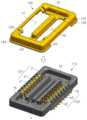
도2는 본 발명의 일 실시예에 의한 리셉터클 커넥터를 나타내는 사시도이고, 도3은 본 발명의 일 실시예에 의한 리셉터클 커넥터를 나타내는 분해사시도이다.Figure 2 is a perspective view showing a receptacle connector according to an embodiment of the present invention, Figure 3 is an exploded perspective view showing a receptacle connector according to an embodiment of the present invention.
도2 및 도3을 참조하면, 본 발명의 일 실시예에 의한 리셉터클 커넥터(100)는 절연 몸체(110), 컨텍트부(120) 및 홀드다운부(hold-down, 130)를 포함할 수 있다.2 and 3, the
이하, 도2 및 도3을 참조하여 본 발명의 일 실시에에 의한 리셉터클 커넥터를 설명한다.Hereinafter, a receptacle connector according to an embodiment of the present invention will be described with reference to FIGS. 2 and 3 .
절연 몸체(110)는 상부면이 오목한 보울(bowl) 형상을 가질 수 있으며, 상부면의 중심에는 융기부(u)를 포함할 수 있다. 여기서, 융기부(u)는 절연 몸체(110)의 길이 방향으로 연장되는 바(bar) 형상으로 형성될 수 있으며, 상부면은 폭방향에 위치하는 제1 내측면(f1) 및 제2 내측면(f2)과, 길이방향에 위치하는 제3 내측면(f3) 및 제4 내측면(f4)을 포함할 수 있다.The
도2 및 도3에 도시한 바와 같이, 절연 몸체(110)에는 컨텍트 핀(c1, c2)이 배치되는 컨텍트부(120)가 형성될 수 있으며, 절연 몸체(110)의 상부면에는 홀드다운부(130)가 조립되어 리셉터클 커넥터(100)를 형성할 수 있다. 여기서, 절연 몸체(110)는 전기가 통하지 않는 플라스틱 등의 절연 소재로 형성될 수 있다.As shown in FIGS. 2 and 3, a
컨텍트부(120)는 절연 몸체(110)의 폭방향에 위치하는 상부면의 내측면(f1, f2)과, 융기부(u) 사이에 각각 형성될 수 있다. 도1에 도시한 바와 같이, 컨텍트부(120)에는 복수의 컨텍트 핀(c1, c2)이 일정한 피치(pitch)로 배열될 수 있으며, 플러그 커넥터(200)의 삽입시 플러그 커넥터(200)와 접점을 형성할 수 있다. 여기서, 컨텍트 핀(c1, c2)들은 절연 몸체(110) 내에 인서트 몰딩(insert mording)하는 방식으로 컨텍트부(120) 내에 배열될 수 있다.The
컨텍트 핀(c1, c2)들은 도전 소재로 이루어질 수 있으며, 플러그 커넥터(200)의 컨텍트 핀 또는 기판과의 전기적 접촉을 위해 마련될 수 있다. 컨텍트 핀(c1, c2)의 일부 영역은 기판과의 접촉을 위해 절연 몸체(110)로부터 노출될 수 있으며, 컨텍트 핀(c1, c2)의 다른 영역은 플러그 커넥터(200)와의 접촉을 위해 절연 몸체(110)로부터 노출될 수 있다.The contact pins c1 and c2 may be made of a conductive material and may be provided for electrical contact with a contact pin of the
구체적으로, 도1 및 도2에 도시한 바와 같이, 컨텍트부(120)는 융기부(u)를 기준으로 제1 컨텍트부(121)와 제2 컨텍트부(122)로 구분할 수 있다.Specifically, as shown in FIGS. 1 and 2 , the
제1 컨텍트부(121)는 폭방향의 일측에 위치하는 절연 몸체(110)의 제1 내측면(f1)과, 제1 내측면(f1)으로부터 이격하여 형성되는 제1 지지부(s1)를 포함할 수 있다. 이 경우, 제1 컨텍트부(121)는, 제1 내측면(f1)과 제1 지지부(s1) 사이에 형성되는 제1 만곡부(b1)를 포함할 수 있다. 도2에 도시한 바와 같이, 컨텍트 핀(c1)은 제1 내측면(f1), 제1 만곡부(b1) 및 제1 지지부(s1)의 표면을 따라 노출되도록 휘어지는 형상을 가질 수 있다.The
제2 컨텍트부(122)는 폭방향의 타측에 위치하는 절연 몸체(110)의 제2 내측면(f2)과, 제2 내측면(f2)으로부터 이격하여 형성되는 제2 지지부(s2)를 포함할 수 있다. 여기서, 제2 내측면(f2)과 제2 지지부(s2) 사이에 제2 만곡부(b2)가 포함되며, 컨텍트 핀(c2)은 제2 내측면(f2), 제2 만곡부(b2) 및 제2 지지부(s2)의 표면을 따라 노출되도록 휘어지는 형상을 가질 수 있다.The
여기서, 제1 지지부(s1)와 제2 지지부(s2)는, 융기부(u)의 양측면에 각각 위치하며, 절연 몸체(110)의 길이방향으로 연장된 바(bar) 형태로 형성될 수 있다. 제1 지지부(s1)와 제2 지지부(s2)는, 융기부(u) 보다 짧거나 같은 길이로 형성될 수 있다.Here, the first support part s1 and the second support part s2 are located on both side surfaces of the raised part u and may be formed in a bar shape extending in the longitudinal direction of the insulating
홀드다운부(130)는 절연 몸체(110)의 형상에 따라 벤딩(bending)하여 형성할 수 있으며, 도3에 도시한 바와 같이, 절연 몸체(110)를 일체로 커버(cover)할 수 있다. 즉, 홀드다운부(130)는 단절된 영역없이 일체로서 절연 몸체(110)의 상부면 전체를 커버하는 것을 확인할 수 있다.The hold-down
홀드다운부(130)는 금속재질로 구현될 수 있으며, 플러그 커넥터(200)와의 결합시 플러그 커넥터(200)를 가이딩하는 기능을 수행할 수 있다. 즉, 홀드다운부(130)는 벤딩을 통하여 형성되므로, 홀드다운부(130)의 내측면 또는 외측면의 모서리들은 완만한 경사를 이룰 수 있다. 따라서, 플러그 커넥터(200)의 결합시, 플러그 커넥터(200)는 홀드다운부(130)의 표면에서 자연스럽게 가이딩될 수 있다.The hold-down
또한, 절연 몸체(110)의 경우, 플라스틱 등 상대적으로 강도가 약한 재질로 형성되므로, 플러그 커넥터(200)의 결합시 가해지는 충격 등에 의하여 파손될 위험이 존재한다. 이를 방지하기 위하여, 금속 재질의 홀드다운부(130)를 절연 몸체(110)의 상부면을 커버하도록 조립할 수 있다. 즉, 금속재질의 강도가 높은 홀드다운부(130)를 이용하여 절연 몸체(110)를 보호함으로써, 절연 몸체(110)의 파손을 방지하고, 리셉터클 커넥터(100)의 강도를 보강할 수 있다.In addition, since the insulating
추가적으로, 도3를 참조하면 홀드다운부(130)는 바닥면(131)을 포함할 수 있다. 바닥면(131)은 절연 몸체(110)의 길이 방향에 위치하는 내측면(f3, f4)과 융기부(u) 사이의 영역을 커버하는 구성에 해당한다. 여기서, 바닥면(31)은 홀드다운부(130)의 내측면과 연결되어 일체로 형성될 수 있다. 사용자는 플러그 커넥터(200)의 삽입시, 바닥면(131)에 해당하는 위치부터 접촉하여 결합시킬 수 있으며, 이때 플러그 커넥터(200)에 의하여 충격이 가해질 수 있다. 또한, 절연 몸체(110)의 내측면(f3, f4)과 융기부(u) 사이의 영역은 상대적으로 두께가 얇기 때문에, 강도가 약할 수 있다. 따라서, 홀드다운부(130)는 바닥면(131)을 더 포함하여 해당 영역의 강도를 보강시킬 수 있다.Additionally, referring to FIG. 3 , the hold-down
한편, 도3에 도시한 바와 같이, 홀드다운부(130)는 통공(h)을 포함할 수 있으며, 통공(h)은 컨텍트부(120)에 대응하는 위치에 형성될 수 있다. 따라서, 도2에 도시한 바와 같이, 컨텍트부(120)는 통공(h)을 통하여 홀드다운부(130)의 외부로 노출될 수 있다. 통공(h)에 의하여 외부로 노출되므로, 플러그 커넥터(200)가 삽입되는 경우, 컨텍트부(120)는 플러그 커넥터(200)와 결합하여 접점을 형성할 수 있다. 여기서, 도4에 도시한 바와 같이, 통공(h)을 통하여 컨텍트부(120)를 외부로 노출할 때, 홀드다운부(130)는 절연 몸체(110)의 외측면을 "ㄱ"자 형상으로 커버하여, 컨텍트부(120) 주위의 강도를 향상시킬 수 있다.Meanwhile, as shown in FIG. 3 , the hold-down
또한, 도3 및 도4를 참조하면, 홀드다운부(130)는 융기부(u)의 외형에 따라 벤딩되어 융기부(u)를 커버하는 융기커버부(132)를 포함할 수 있다. 여기서, 융기커버부(132)는 금속 재질의 전도성 물질이므로, 융기커버부(132)의 양측에 위치하는 각각의 제1 컨텍트부(121)와 제2 컨텍트부(122)를 전기적으로 차폐하는 기능을 수행할 수 있다. 이때, 홀드다운부(130)는 접지와 연결되어 있을 수 있다.Also, referring to FIGS. 3 and 4 , the hold-down
여기서, 융기커버부(132)는 단면이 돔(dome) 형상으로 구현되므로, 외부의 충격에 대한 파손 강도를 향상시킬 수 있으며, 융기커버부(132)는 내부에 융기부(u)를 포함하므로, 외부의 압력 등에 대해 상대적으로 높은 좌굴강도를 가질 수 있다.Here, since the raised
추가적으로, 도5를 참조하면, 융기커버부(132)가 제1 지지부(s1) 및 제2 지지부(s2)보다 길이방향으로 설정길이(d)만큼 더 돌출된 것을 확인할 수 있다. 융기커버부(132)는 금속재질로 구현되므로, 플라스틱 등으로 구현되는 제1 지지부(s1)나 제2 지지부(s2)에 비하여 상대적으로 강성이 높다. 플러그 커넥터(200)의 체결시, 제1 지지부(s1)나 제2 지지부(s2)가 플러그 커넥터(200)와 접촉하게 되면, 제1 지지부(s1)나 제2 지지부(s2)는 파손될 위험성이 높다. 따라서, 이를 방지하기 위하여, 융기커버부(132)가 제1 지지부(s1)나 제2 지지부(s2) 보다 먼저 플러그 커넥터(200)와 접촉할 수 있도록, 융기커버부(132)를 설정길이(d)만큼 더 돌출되도록 형성할 수 있다. 여기서, 설정길이(d)는 다양하게 설정할 수 있으며, 실시예에 따라서는 융기커버부(132)의 두께로 설정할 수 있다.Additionally, referring to FIG. 5 , it can be seen that the raised
한편, 홀드다운부(130)는 접촉부(133)를 더 포함할 수 있다. 도2에 도시한 바와 같이, 접촉부(133)는 통공(h) 내로 길게 돌출되는 형상을 가질 수 있으며, 돌출된 형상에 의해 탄성을 가질 수 있다. 접촉부(133)는 플러그 커넥터(200)의 삽입시 플러그 커넥터에 의하여 압착될 수 있으며, 이를 통하여 리셉터클 커넥터(100)와 플러그 커넥터(200) 사이의 접촉 신뢰성을 향상시킬 수 있다. 여기서, 홀드다운부(130)는 접지와 연결될 수 있으므로, 접촉부(133)는 플러그 커넥터(200)에 접지를 제공할 수 있다. 접촉부(133)의 형상이나 개수는 실시예에 따라 다양하게 설정될 수 있다.Meanwhile, the hold-down
추가적으로, 홀드다운부(130)는 리셉터클 커넥터(100)를 기판에 솔더링(soldering)하기 위한 솔더링부(134)를 더 포함할 수 있다. 솔더링부(134)는 홀드다운부(130)의 하부면에 형성될 수 있으며, 도6에 도시한 바와 같이, 기판의 솔더링 영역(p)에 대응하여 형성될 수 있다. 즉, 솔더링부(134)는 홀드다운부(130)의 하부면의 둘레를 따라 형성될 수 있으며, 컨텍트부(120)의 컨텍트 핀(c1, c2)이 돌출되는 영역에는 솔더링부(134)가 형성되지 않을 수 있다. 솔더링부(134)에 의하여, 홀드다운부(130)가 기판의 솔더링 영역(p)과 접촉하는 면적이 확대될 수 있으며, 이를 통해 리셉터클 커넥터(100)와 기판 사이의 접촉력을 증대시킬 수 있다.Additionally, the hold-down
이외에도, 홀드다운부(130)의 내측면에는, 플러그 커넥터(200)와의 결합을 위한 홈 또는 돌기(e1)들이 형성될 수 있다. 이때, 플러그 커넥터(200)에는 홀드다운부(130)에 생성된 홈 또는 돌기(e1)에 대응하는 돌기 또는 홈이 형성되어 있을 수 있으며, 홈과 돌기 사이의 결합을 통하여 리셉터클 커넥터(100)와 플러그 커넥터(200) 사이의 안정적인 결합을 유지시킬 수 있다.In addition, grooves or protrusions e1 for coupling with the
실시예에 따라서는, 홀드다운부(130)의 외측면에도 홈(e2)이 포함될 수 있다. 여기서, 홀드다운부(130)의 외측면에 형성되는 홈(e2)은 절연 몸체(110)와의 안정적인 결합을 위해 형성되는 것으로서, 홀드다운부(130)가 절연 몸체(110)로부터 벗겨지는 것을 방지하는 기능을 수행할 수 있다.Depending on the embodiment, the groove e2 may also be included on the outer surface of the hold-down
본 발명은 전술한 실시예 및 첨부된 도면에 의해 한정되는 것이 아니다. 본 발명이 속하는 기술분야에서 통상의 지식을 가진 자에게 있어, 본 발명의 기술적 사상을 벗어나지 않는 범위 내에서 본 발명에 따른 구성요소를 치환, 변형 및 변경할 수 있다는 것이 명백할 것이다.The present invention is not limited by the foregoing embodiments and accompanying drawings. It will be clear to those skilled in the art that the components according to the present invention can be substituted, modified, and changed without departing from the technical spirit of the present invention.
100: 리셉터클 커넥터110: 절연 몸체
120: 컨텍트부121: 제1 컨텍트부
122: 제2 컨텍트부130: 홀드다운부
131: 바닥면132: 융기커버부
133: 접촉부134: 솔더링부100: receptacle connector 110: insulation body
120: contact part 121: first contact part
122: second contact part 130: hold-down part
131: bottom surface 132: raised cover portion
133: contact part 134: soldering part
Claims (21)
Translated fromKorean상기 공간을 적어도 부분적으로 덮으며 상기 절연 몸체(110)와 결합되는 홀드다운(hold-down)부(130)를 포함하며,
상기 절연 몸체(110)는,
상기 공간을 상기 길이 방향에서 둘러싸는 내측면(f3);
상기 내측면(f3)의 상측과 연속되며, 상기 길이 방향의 외측으로 연장되는 상면;
상기 내측면(f3)의 하측과 연속되며, 상기 길이 방향의 내측으로 연장되어 상기 공간을 하측에서 둘러싸는 하면을 포함하고,
상기 홀드다운부(130)는,
상기 폭 방향으로 연장되고, 상기 내측면(f3)을 덮는 제1 면;
상기 제1 면의 상측과 연속되며, 상기 상면을 덮는 제2 면; 및
상기 제1 면의 하측과 연속되며, 상기 하면을 덮는 바닥면(131)을 포함하고,
상기 제1 면은 상기 제2 면 및 상기 바닥면(131)과 각각 연속되는 면으로 형성되는,
리셉터클 커넥터(receptacle connector).Insulation body 110 including a recessed space radially inside the outer periphery of which a direction in which a plurality of contact pins are arranged side by side is a longitudinal direction and a direction perpendicular to the longitudinal direction is a width direction; and
At least partially covering the space and including a hold-down portion 130 coupled to the insulating body 110,
The insulating body 110,
an inner surface (f3) surrounding the space in the longitudinal direction;
an upper surface continuous with an upper side of the inner surface f3 and extending outward in the longitudinal direction;
It is continuous with the lower side of the inner surface (f3) and includes a lower surface extending inwardly in the longitudinal direction to surround the space from the lower side,
The hold-down unit 130,
a first surface extending in the width direction and covering the inner surface f3;
a second surface continuous with an upper side of the first surface and covering the upper surface; and
It is continuous with the lower side of the first surface and includes a bottom surface 131 covering the lower surface,
The first surface is formed of a surface that is continuous with the second surface and the bottom surface 131, respectively.
Receptacle connector.
상기 제1 면과 상기 제2 면이 연속되는 부분은 상기 길이 방향의 내측 및 상측을 향해 볼록한 곡면으로 형성되고,
상기 제1 면과 상기 바닥면(131)이 연속되는 부분은 길이 방향의 외측 및 하측을 향해 볼록한 곡면으로 형성되는,
리셉터클 커넥터.According to claim 1,
The portion where the first surface and the second surface are continuous is formed as a convex curved surface toward the inside and the upper side in the longitudinal direction,
The part where the first surface and the bottom surface 131 are continuous is formed as a convex curved surface toward the outer and lower sides in the longitudinal direction,
Receptacle connector.
상기 제1 면은 상기 폭 방향으로 연장되고, 상기 제1 면의 각 단부는 라운드지게 형성되는,
리셉터클 커넥터.According to claim 1,
The first surface extends in the width direction, and each end of the first surface is formed to be rounded.
Receptacle connector.
상기 제1 면의 각 단부는, 상기 길이 방향 및 상기 폭 방향의 사이의 외측으로 볼록한 곡면으로 형성되는,
리셉터클 커넥터.According to claim 3,
Each end of the first surface is formed as an outwardly convex curved surface between the longitudinal direction and the width direction,
Receptacle connector.
상기 제2 면은 상기 폭 방향으로 연장되고, 상기 제2 면의 각 단부는 라운드지게 형성되는,
리셉터클 커넥터.According to claim 3,
The second surface extends in the width direction, and each end of the second surface is formed to be rounded.
Receptacle connector.
상기 제2 면의 각 단부는, 상기 길이 방향 및 상기 폭 방향의 사이의 외측으로 볼록한 곡면으로 형성되고,
상기 제1 면의 상기 각 단부의 상측과 상기 제2 면의 상기 각 단부의 하측은 서로 연속되는,
리셉터클 커넥터.According to claim 5,
Each end of the second surface is formed as an outwardly convex curved surface between the longitudinal direction and the width direction,
The upper side of each end of the first surface and the lower side of each end of the second surface are continuous with each other,
Receptacle connector.
상기 제1 면의 상기 각 단부의 하측은 상기 바닥면과 연속되는,
리셉터클 커넥터.According to claim 3,
The lower side of each end of the first surface is continuous with the bottom surface,
Receptacle connector.
상기 제1 면의 상기 각 단부의 상기 하측과 상기 바닥면이 연속되는 부분은, 상기 길이 방향 및 상기 폭 방향의 외측으로 볼록한 곡면으로 형성되는,
리셉터클 커넥터.According to claim 7,
The lower part of each end of the first surface and the bottom surface are continuous, formed as a convex curved surface outward in the longitudinal direction and the width direction,
Receptacle connector.
상기 절연 몸체(110)는,
상기 내측면(f3)과 이격되게 상기 공간에 위치되고, 상기 길이 방향을 따라 연장되는 융기부(u)를 포함하고,
상기 홀드다운부(130)는,
상기 바닥면(131)과 연속되며, 상기 융기부(u)를 덮는 융기커버부(132)를 포함하고,
상기 바닥면(131)이 상기 융기커버부(132)와 연속되는 부분은 연속적인 면으로 형성되는,
리셉터클 커넥터.According to claim 1,
The insulating body 110,
It is located in the space to be spaced apart from the inner surface (f3) and includes a raised portion (u) extending along the longitudinal direction,
The hold-down unit 130,
It is continuous with the bottom surface 131 and includes a raised cover portion 132 covering the raised portion u,
Where the bottom surface 131 is continuous with the raised cover portion 132 is formed as a continuous surface,
Receptacle connector.
상기 공간을 적어도 부분적으로 덮으며 상기 절연 몸체(110)와 결합되는 홀드다운부(130)를 포함하며,
상기 절연 몸체(110)는,
상기 공간을 상기 길이 방향에서 둘러싸는 내측면(f3);
상기 길이 방향을 따라 상기 내측면(f3)과 이격되고, 상기 공간에 위치되는 융기부(u); 및
상기 내측면(f3)의 하측 및 상기 융기부(u) 사이에서 연장되고, 상기 공간을 하측에서 둘러싸는 하면을 포함하며,
상기 홀드다운부(130)는,
상기 폭 방향으로 연장되고, 상기 내측면(f3)을 덮는 제1 면;
상기 제1 면의 하측과 연속되며, 상기 하면을 덮는 바닥면(131); 및
상기 바닥면(131)과 연속되며, 상기 융기부(u)를 덮는 융기커버부(132)를 포함하고,
상기 바닥면(131)이 상기 제1 면 및 상기 융기커버부(132)와 연속되는 각 부분은 연속적인 면으로 형성되는,
리셉터클 커넥터.Insulation body 110 including a recessed space radially inside the outer periphery of which a direction in which a plurality of contact pins are arranged side by side is a longitudinal direction and a direction perpendicular to the longitudinal direction is a width direction; and
At least partially covering the space and including a hold-down portion 130 coupled to the insulating body 110,
The insulating body 110,
an inner surface (f3) surrounding the space in the longitudinal direction;
a raised portion (u) spaced apart from the inner surface (f3) along the longitudinal direction and located in the space; and
It extends between the lower side of the inner surface (f3) and the raised portion (u) and includes a lower surface surrounding the space from the lower side,
The hold-down unit 130,
a first surface extending in the width direction and covering the inner surface f3;
a bottom surface 131 continuous with the lower side of the first surface and covering the lower surface; and
It is continuous with the bottom surface 131 and includes a raised cover portion 132 covering the raised portion u,
Each part where the bottom surface 131 is continuous with the first surface and the raised cover portion 132 is formed as a continuous surface,
Receptacle connector.
상기 융기커버부(132)는 상기 길이 방향으로 연장되고,
상기 융기커버부(132)의 단부 중 상기 제1 면을 향하는 일 단부는 상기 제1 면을 향해 볼록하도록 라운드지게 형성되는,
리셉터클 커넥터.According to claim 10,
The raised cover portion 132 extends in the longitudinal direction,
Of the ends of the raised cover portion 132, one end facing the first surface is formed round to be convex toward the first surface.
Receptacle connector.
상기 바닥면(131)은, 상기 융기커버부(132)의 상기 일 단부의 하측과 연속되고,
상기 바닥면(131)과 상기 융기커버부(132)의 상기 일 단부가 연속되는 부분은 라운드지게 형성되는,
리셉터클 커넥터.According to claim 11,
The bottom surface 131 is continuous with the lower side of the one end of the raised cover part 132,
The part where the bottom surface 131 and the one end of the raised cover portion 132 are continuous is formed round.
Receptacle connector.
상기 바닥면(131)과 상기 융기커버부(132)의 상기 일 단부가 연속되는 상기 부분은 상기 길이 방향의 내측 및 하측을 향해 볼록하도록 라운드지게 형성되는,
리셉터클 커넥터.According to claim 12,
The portion where the bottom surface 131 and the one end of the raised cover portion 132 are continuous is formed round to be convex toward the inner and lower sides in the longitudinal direction,
Receptacle connector.
상기 제1 면은 상기 폭 방향으로 연장되고, 상기 제1 면의 각 단부는 라운드지게 형성되는,
리셉터클 커넥터.According to claim 10,
The first surface extends in the width direction, and each end of the first surface is formed to be rounded.
Receptacle connector.
상기 공간을 적어도 부분적으로 덮으며 상기 절연 몸체(110)와 결합되는 홀드다운부(130)를 포함하며,
상기 절연 몸체(110)는,
상기 공간을 상기 길이 방향에서 둘러싸는 내측면(f3);
상기 내측면(f3)의 상측과 연속되며, 상기 길이 방향의 외측으로 연장되는 상면;
상기 상면과 연속되며, 상기 내측면(f3)을 마주하며 상기 폭 방향으로 연장되는 외측면을 포함하고,
홀드다운부(130)는,
상기 폭 방향으로 연장되고, 상기 내측면(f3)을 덮는 제1 면;
상기 제1 면의 상측과 연속되며, 상기 상면을 덮는 제2 면; 및
상기 제2 면과 연속되며, 상기 외측면을 덮는 제3 면을 포함하며,
상기 제2 면이 상기 제1 면 및 상기 제3 면과 연속되는 각 부분은 연속적인 면으로 형성되는,
리셉터클 커넥터.Insulation body 110 including a recessed space radially inside the outer circumference in which a direction in which a plurality of contact pins are disposed parallel to each other is a longitudinal direction and a direction perpendicular to the longitudinal direction is a width direction; and
At least partially covering the space and including a hold-down portion 130 coupled to the insulating body 110,
The insulating body 110,
an inner surface (f3) surrounding the space in the longitudinal direction;
an upper surface continuous with an upper side of the inner surface f3 and extending outward in the longitudinal direction;
It is continuous with the upper surface, and includes an outer surface extending in the width direction while facing the inner surface (f3),
The hold-down unit 130,
a first surface extending in the width direction and covering the inner surface f3;
a second surface continuous with an upper side of the first surface and covering the upper surface; and
It is continuous with the second surface and includes a third surface covering the outer surface,
Each part where the second surface is continuous with the first surface and the third surface is formed as a continuous surface,
Receptacle connector.
상기 제1 면과 상기 제2 면이 연속되는 부분은 상기 길이 방향의 내측 및 상측을 향해 볼록한 곡면으로 형성되고,
상기 제2 면과 상기 제3 면이 연속되는 부분은 길이 방향의 외측 및 상측을 향해 볼록한 곡면으로 형성되는,
리셉터클 커넥터.According to claim 15,
The portion where the first surface and the second surface are continuous is formed as a convex curved surface toward the inside and the upper side in the longitudinal direction,
The part where the second surface and the third surface are continuous is formed as a convex curved surface toward the outer and upper sides in the longitudinal direction,
Receptacle connector.
상기 제1 면, 상기 제2 면 및 상기 제3 면은 상기 폭 방향으로 연장되고,
상기 제2 면의 각 단부는, 상기 제1 면의 각 단부 및 상기 제3 면의 각 단부와 각각 연속되는,
리셉터클 커넥터.According to claim 16,
The first surface, the second surface and the third surface extend in the width direction,
Each end of the second surface is continuous with each end of the first surface and each end of the third surface, respectively.
Receptacle connector.
상기 제1 면의 상기 각 단부, 상기 제2 면의 상기 각 단부 및 상기 제3 면의 상기 각 단부는, 상기 길이 방향 및 상기 폭 방향의 외측으로 볼록한 곡면으로 형성되는,
리셉터클 커넥터.According to claim 17,
The respective ends of the first surface, the respective ends of the second surface, and the respective ends of the third surface are formed as convex curved surfaces outwardly in the longitudinal direction and the width direction,
Receptacle connector.
상기 제2 면의 상기 각 단부의 상기 길이 방향 및 상기 폭 방향의 내측은, 상기 제1 면의 상기 각 단부의 상기 길이 방향 및 상기 폭 방향의 외측과 라운드지게 연속되고,
상기 제2 면의 상기 각 단부의 상기 길이 방향 및 상기 폭 방향의 외측은, 상기 제3 면의 상기 각 단부의 상기 길이 방향 및 상기 폭 방향의 내측과 라운드지게 연속되는,
리셉터클 커넥터.According to claim 18,
The inner side of each end of the second surface in the longitudinal direction and the width direction is continuously rounded with the outer side of each end of the first surface in the longitudinal direction and the width direction,
The outer side of each end of the second surface in the longitudinal direction and the width direction is continuously rounded with the inner side of each end of the third surface in the longitudinal direction and the width direction.
Receptacle connector.
상기 제2 면의 상기 각 단부의 상기 길이 방향 및 상기 폭 방향의 내측은, 상기 제1 면의 상기 각 단부의 상기 길이 방향 및 상기 폭 방향의 외측과 라운드지게 연속되고,
상기 제2 면의 상기 각 단부의 상기 길이 방향 및 상기 폭 방향의 외측은, 상기 제3 면의 상기 각 단부의 상기 길이 방향 및 상기 폭 방향의 내측과 라운드지게 연속되는,
리셉터클 커넥터.According to claim 17,
The inner side of each end of the second surface in the longitudinal direction and the width direction is continuously rounded with the outer side of each end of the first surface in the longitudinal direction and the width direction,
The outer side of each end of the second surface in the longitudinal direction and the width direction is continuously rounded with the inner side of each end of the third surface in the longitudinal direction and the width direction.
Receptacle connector.
상기 절연 몸체(110)는,
상기 내측면(f3)의 하측과 연속되며, 상기 길이 방향의 내측으로 연장되어 상기 공간을 하측에서 둘러싸는 하면; 및
상기 내측면(f3)과 이격되게 상기 공간에 위치되고, 상기 길이 방향을 따라 연장되는 융기부(u)를 포함하고,
상기 홀드다운부(130)는,
상기 제1 면의 하측과 연속되며, 상기 하면을 덮는 바닥면(131); 및
상기 바닥면(131)과 연속되며, 상기 융기부(u)를 덮는 융기커버부(132)를 포함하고,
상기 제1 면이 상기 바닥면(131) 및 상기 융기커버부(132)와 연속되는 부분은 각각 연속적인 면으로 형성되는,
리셉터클 커넥터.According to claim 15,
The insulating body 110,
a lower surface continuous with the lower side of the inner surface f3 and extending inwardly in the longitudinal direction to surround the space from the lower side; and
It is located in the space to be spaced apart from the inner surface (f3) and includes a raised portion (u) extending along the longitudinal direction,
The hold-down unit 130,
a bottom surface 131 continuous with the lower side of the first surface and covering the lower surface; and
It is continuous with the bottom surface 131 and includes a raised cover portion 132 covering the raised portion u,
Where the first surface is continuous with the bottom surface 131 and the raised cover portion 132 is formed as a continuous surface, respectively.
Receptacle connector.
Priority Applications (1)
| Application Number | Priority Date | Filing Date | Title |
|---|---|---|---|
| KR1020230013536AKR102631033B1 (en) | 2018-07-17 | 2023-02-01 | receptacle connector |
Applications Claiming Priority (2)
| Application Number | Priority Date | Filing Date | Title |
|---|---|---|---|
| KR1020180083002AKR102590445B1 (en) | 2018-07-17 | 2018-07-17 | receptacle connector |
| KR1020230013536AKR102631033B1 (en) | 2018-07-17 | 2023-02-01 | receptacle connector |
Related Parent Applications (1)
| Application Number | Title | Priority Date | Filing Date |
|---|---|---|---|
| KR1020180083002ADivisionKR102590445B1 (en) | 2018-07-17 | 2018-07-17 | receptacle connector |
Publications (2)
| Publication Number | Publication Date |
|---|---|
| KR20230019919Atrue KR20230019919A (en) | 2023-02-09 |
| KR102631033B1 KR102631033B1 (en) | 2024-01-30 |
Family
ID=69322464
Family Applications (3)
| Application Number | Title | Priority Date | Filing Date |
|---|---|---|---|
| KR1020180083002AActiveKR102590445B1 (en) | 2018-07-17 | 2018-07-17 | receptacle connector |
| KR1020230013536AActiveKR102631033B1 (en) | 2018-07-17 | 2023-02-01 | receptacle connector |
| KR1020230135829AActiveKR102638554B1 (en) | 2018-07-17 | 2023-10-12 | receptacle connector |
Family Applications Before (1)
| Application Number | Title | Priority Date | Filing Date |
|---|---|---|---|
| KR1020180083002AActiveKR102590445B1 (en) | 2018-07-17 | 2018-07-17 | receptacle connector |
Family Applications After (1)
| Application Number | Title | Priority Date | Filing Date |
|---|---|---|---|
| KR1020230135829AActiveKR102638554B1 (en) | 2018-07-17 | 2023-10-12 | receptacle connector |
Country Status (1)
| Country | Link |
|---|---|
| KR (3) | KR102590445B1 (en) |
Cited By (4)
| Publication number | Priority date | Publication date | Assignee | Title |
|---|---|---|---|---|
| KR20240111699A (en) | 2023-01-10 | 2024-07-17 | 엘에스엠트론 주식회사 | Connector |
| KR20240111693A (en) | 2023-01-10 | 2024-07-17 | 엘에스엠트론 주식회사 | Connector |
| KR20240111697A (en) | 2023-01-10 | 2024-07-17 | 엘에스엠트론 주식회사 | Connector |
| KR20240111695A (en) | 2023-01-10 | 2024-07-17 | 엘에스엠트론 주식회사 | Connector |
Families Citing this family (20)
| Publication number | Priority date | Publication date | Assignee | Title |
|---|---|---|---|---|
| CN114938692B (en) | 2020-02-14 | 2025-07-22 | Ls美创有限公司 | Substrate connector |
| WO2021177609A1 (en)* | 2020-03-06 | 2021-09-10 | 엘에스엠트론 주식회사 | Board connector |
| JP7430818B2 (en)* | 2020-03-19 | 2024-02-13 | エル エス エムトロン リミテッド | board connector |
| KR102675705B1 (en)* | 2020-03-19 | 2024-06-17 | 엘에스엠트론 주식회사 | Substrate Connector |
| CN113675650B (en)* | 2020-05-13 | 2025-04-01 | 日本航空电子工业株式会社 | Connectors |
| KR102623602B1 (en)* | 2020-05-13 | 2024-01-10 | 니혼 고꾸 덴시 고교 가부시끼가이샤 | Connector |
| US11652323B2 (en)* | 2020-05-13 | 2023-05-16 | Japan Aviation Electronics Industry, Limited | Connector assembly comprising a connector encolsed by a shell and a mating connector enclosed by a mating shell |
| KR102706646B1 (en)* | 2020-11-20 | 2024-09-13 | 엘에스엠트론 주식회사 | Substrate Connector |
| US20230411911A1 (en)* | 2020-11-20 | 2023-12-21 | Ls Mtron Ltd. | Board connector |
| US20240145998A1 (en)* | 2021-03-17 | 2024-05-02 | Ls Mtron Ltd. | Board connector |
| TWI825839B (en)* | 2021-08-16 | 2023-12-11 | 日商日本航空電子工業股份有限公司 | Connector |
| US12261384B2 (en)* | 2021-08-31 | 2025-03-25 | Japan Aviation Electronics Industry, Ltd | Socket connector |
| JP7686350B2 (en)* | 2021-09-17 | 2025-06-02 | 日本航空電子工業株式会社 | Socket Connector |
| JP2023039864A (en)* | 2021-09-09 | 2023-03-22 | パナソニックIpマネジメント株式会社 | Connector and connector assembly |
| KR102734765B1 (en)* | 2022-06-21 | 2024-11-28 | 몰렉스 엘엘씨 | Receptacle fitting nail, receptacle connector and board-to-board connector assembly including the same |
| KR102838877B1 (en)* | 2023-01-18 | 2025-07-25 | 에이치알에스코리아 주식회사 | Electric connector |
| KR20240124175A (en) | 2023-02-08 | 2024-08-16 | 엘에스엠트론 주식회사 | Plug connector and receptacle connector |
| KR20240124212A (en) | 2023-02-08 | 2024-08-16 | 엘에스엠트론 주식회사 | Plug connector and receptacle connector |
| KR20240129575A (en) | 2023-02-20 | 2024-08-27 | 엘에스엠트론 주식회사 | Receptacle connector and plug connector |
| KR20250119226A (en) | 2024-01-31 | 2025-08-07 | 엘에스엠트론 주식회사 | Plug connector and receptacle connector |
Citations (12)
| Publication number | Priority date | Publication date | Assignee | Title |
|---|---|---|---|---|
| KR20110066847A (en)* | 2009-12-03 | 2011-06-17 | 히로세덴끼 가부시끼가이샤 | Electrical connector |
| KR20110074824A (en)* | 2011-05-18 | 2011-07-04 | 엘에스엠트론 주식회사 | Connector unit with fastening guide |
| KR101488892B1 (en)* | 2013-08-08 | 2015-02-02 | 엘에스엠트론 주식회사 | Connector assembly for board-to-board |
| JP2015207557A (en)* | 2014-04-17 | 2015-11-19 | タイコ エレクトロニクス (シャンハイ) カンパニー リミテッド | Terminal, electric connector, and electric connector assembly |
| JP2016009619A (en)* | 2014-06-25 | 2016-01-18 | モレックス エルエルシー | connector |
| KR20160076733A (en)* | 2014-12-23 | 2016-07-01 | 엘에스엠트론 주식회사 | Improved connector device for hold-down structure |
| CN106299878A (en)* | 2015-05-14 | 2017-01-04 | 昆山嘉华电子有限公司 | Electric connector |
| KR20170015126A (en)* | 2015-07-29 | 2017-02-08 | 다이-이치 세이코 가부시키가이샤 | Substrate-connecting electric connector device |
| JP2017103119A (en)* | 2015-12-02 | 2017-06-08 | 第一精工株式会社 | Electrical connector |
| JP2017147171A (en)* | 2016-02-19 | 2017-08-24 | タイコエレクトロニクスジャパン合同会社 | connector |
| KR20170106911A (en)* | 2016-03-14 | 2017-09-22 | 니혼 고꾸 덴시 고교 가부시끼가이샤 | Connector |
| JP2019061883A (en)* | 2017-09-27 | 2019-04-18 | 株式会社村田製作所 | Method of manufacturing connector |
- 2018
- 2018-07-17KRKR1020180083002Apatent/KR102590445B1/enactiveActive
- 2023
- 2023-02-01KRKR1020230013536Apatent/KR102631033B1/enactiveActive
- 2023-10-12KRKR1020230135829Apatent/KR102638554B1/enactiveActive
Patent Citations (12)
| Publication number | Priority date | Publication date | Assignee | Title |
|---|---|---|---|---|
| KR20110066847A (en)* | 2009-12-03 | 2011-06-17 | 히로세덴끼 가부시끼가이샤 | Electrical connector |
| KR20110074824A (en)* | 2011-05-18 | 2011-07-04 | 엘에스엠트론 주식회사 | Connector unit with fastening guide |
| KR101488892B1 (en)* | 2013-08-08 | 2015-02-02 | 엘에스엠트론 주식회사 | Connector assembly for board-to-board |
| JP2015207557A (en)* | 2014-04-17 | 2015-11-19 | タイコ エレクトロニクス (シャンハイ) カンパニー リミテッド | Terminal, electric connector, and electric connector assembly |
| JP2016009619A (en)* | 2014-06-25 | 2016-01-18 | モレックス エルエルシー | connector |
| KR20160076733A (en)* | 2014-12-23 | 2016-07-01 | 엘에스엠트론 주식회사 | Improved connector device for hold-down structure |
| CN106299878A (en)* | 2015-05-14 | 2017-01-04 | 昆山嘉华电子有限公司 | Electric connector |
| KR20170015126A (en)* | 2015-07-29 | 2017-02-08 | 다이-이치 세이코 가부시키가이샤 | Substrate-connecting electric connector device |
| JP2017103119A (en)* | 2015-12-02 | 2017-06-08 | 第一精工株式会社 | Electrical connector |
| JP2017147171A (en)* | 2016-02-19 | 2017-08-24 | タイコエレクトロニクスジャパン合同会社 | connector |
| KR20170106911A (en)* | 2016-03-14 | 2017-09-22 | 니혼 고꾸 덴시 고교 가부시끼가이샤 | Connector |
| JP2019061883A (en)* | 2017-09-27 | 2019-04-18 | 株式会社村田製作所 | Method of manufacturing connector |
Cited By (4)
| Publication number | Priority date | Publication date | Assignee | Title |
|---|---|---|---|---|
| KR20240111699A (en) | 2023-01-10 | 2024-07-17 | 엘에스엠트론 주식회사 | Connector |
| KR20240111693A (en) | 2023-01-10 | 2024-07-17 | 엘에스엠트론 주식회사 | Connector |
| KR20240111697A (en) | 2023-01-10 | 2024-07-17 | 엘에스엠트론 주식회사 | Connector |
| KR20240111695A (en) | 2023-01-10 | 2024-07-17 | 엘에스엠트론 주식회사 | Connector |
Also Published As
| Publication number | Publication date |
|---|---|
| KR102631033B1 (en) | 2024-01-30 |
| KR102590445B1 (en) | 2023-10-16 |
| KR20200008840A (en) | 2020-01-29 |
| KR102590445B9 (en) | 2025-04-30 |
| KR20230145310A (en) | 2023-10-17 |
| KR102638554B1 (en) | 2024-02-19 |
Similar Documents
| Publication | Publication Date | Title |
|---|---|---|
| KR102631033B1 (en) | receptacle connector | |
| CN110050393B (en) | Shielding type plate-to-plate connector | |
| KR102772011B1 (en) | Receptacle connector and plug connector | |
| US9647393B2 (en) | Electrical receptacle connector | |
| KR102063296B1 (en) | Improved connector device for connection structure | |
| JP2021009836A (en) | Multi-channel connector and assembly thereof | |
| US10381776B2 (en) | Connector assembly with an improved latch member having a shorter length | |
| CN113054472B (en) | Substrate mating connector | |
| US6623301B2 (en) | Plug connector for electronic devices | |
| KR101344933B1 (en) | Connector assembly | |
| US20060094284A1 (en) | Coupler for flat cables and electrical connector assembly | |
| US7052286B2 (en) | Electrical connector with cover | |
| US9553412B2 (en) | Electronic connector | |
| US8790134B2 (en) | Connector, cable assembly, and semiconductor testing device | |
| CN113054473A (en) | Substrate mating connector | |
| US10320124B1 (en) | Electrical connector with internal terminals having opposite sides located from connector internal sidewalls | |
| US9455511B1 (en) | Circuit board connecting device | |
| US7104824B2 (en) | Connectors for connecting mating connectors to connection objects | |
| US7575466B2 (en) | Electrical connector | |
| KR102711510B1 (en) | Board mating connectors and board mating assembliy comprising the same | |
| US20070087595A1 (en) | Electrical connector with improved housing | |
| JP7100168B2 (en) | Shielded board-to-board connector | |
| KR102804340B1 (en) | plug connector | |
| CN210489982U (en) | Improved board connector | |
| KR101113500B1 (en) | Connector device improved in coupling structure between receptacle and plug |
Legal Events
| Date | Code | Title | Description |
|---|---|---|---|
| A107 | Divisional application of patent | ||
| PA0107 | Divisional application | Comment text:Divisional Application of Patent Patent event date:20230201 Patent event code:PA01071R01D Filing date:20180717 Application number text:1020180083002 | |
| PG1501 | Laying open of application | ||
| A201 | Request for examination | ||
| A302 | Request for accelerated examination | ||
| PA0201 | Request for examination | Patent event code:PA02012R01D Patent event date:20230222 Comment text:Request for Examination of Application Patent event code:PA02011R04I Patent event date:20230201 Comment text:Divisional Application of Patent | |
| PA0302 | Request for accelerated examination | Patent event date:20230222 Patent event code:PA03022R01D Comment text:Request for Accelerated Examination Patent event date:20230201 Patent event code:PA03021R04I Comment text:Divisional Application of Patent | |
| E902 | Notification of reason for refusal | ||
| PE0902 | Notice of grounds for rejection | Comment text:Notification of reason for refusal Patent event date:20230713 Patent event code:PE09021S01D | |
| E701 | Decision to grant or registration of patent right | ||
| PE0701 | Decision of registration | Patent event code:PE07011S01D Comment text:Decision to Grant Registration Patent event date:20231113 | |
| GRNT | Written decision to grant | ||
| PR0701 | Registration of establishment | Comment text:Registration of Establishment Patent event date:20240125 Patent event code:PR07011E01D | |
| PR1002 | Payment of registration fee | Payment date:20240125 End annual number:3 Start annual number:1 | |
| PG1601 | Publication of registration |