KR20230017865A - Refresh management for DRAM - Google Patents
Refresh management for DRAMDownload PDFInfo
- Publication number
- KR20230017865A KR20230017865AKR1020227046090AKR20227046090AKR20230017865AKR 20230017865 AKR20230017865 AKR 20230017865AKR 1020227046090 AKR1020227046090 AKR 1020227046090AKR 20227046090 AKR20227046090 AKR 20227046090AKR 20230017865 AKR20230017865 AKR 20230017865A
- Authority
- KR
- South Korea
- Prior art keywords
- memory
- commands
- refresh
- command
- bank
- Prior art date
- Legal status (The legal status is an assumption and is not a legal conclusion. Google has not performed a legal analysis and makes no representation as to the accuracy of the status listed.)
- Pending
Links
Images


Classifications
- G—PHYSICS
- G06—COMPUTING OR CALCULATING; COUNTING
- G06F—ELECTRIC DIGITAL DATA PROCESSING
- G06F11/00—Error detection; Error correction; Monitoring
- G06F11/07—Responding to the occurrence of a fault, e.g. fault tolerance
- G06F11/14—Error detection or correction of the data by redundancy in operation
- G06F11/1402—Saving, restoring, recovering or retrying
- G06F11/1415—Saving, restoring, recovering or retrying at system level
- G06F11/1443—Transmit or communication errors
- G—PHYSICS
- G11—INFORMATION STORAGE
- G11C—STATIC STORES
- G11C11/00—Digital stores characterised by the use of particular electric or magnetic storage elements; Storage elements therefor
- G11C11/21—Digital stores characterised by the use of particular electric or magnetic storage elements; Storage elements therefor using electric elements
- G11C11/34—Digital stores characterised by the use of particular electric or magnetic storage elements; Storage elements therefor using electric elements using semiconductor devices
- G11C11/40—Digital stores characterised by the use of particular electric or magnetic storage elements; Storage elements therefor using electric elements using semiconductor devices using transistors
- G11C11/401—Digital stores characterised by the use of particular electric or magnetic storage elements; Storage elements therefor using electric elements using semiconductor devices using transistors forming cells needing refreshing or charge regeneration, i.e. dynamic cells
- G11C11/406—Management or control of the refreshing or charge-regeneration cycles
- G11C11/40603—Arbitration, priority and concurrent access to memory cells for read/write or refresh operations
- G—PHYSICS
- G06—COMPUTING OR CALCULATING; COUNTING
- G06F—ELECTRIC DIGITAL DATA PROCESSING
- G06F13/00—Interconnection of, or transfer of information or other signals between, memories, input/output devices or central processing units
- G06F13/14—Handling requests for interconnection or transfer
- G06F13/16—Handling requests for interconnection or transfer for access to memory bus
- G06F13/1605—Handling requests for interconnection or transfer for access to memory bus based on arbitration
- G06F13/161—Handling requests for interconnection or transfer for access to memory bus based on arbitration with latency improvement
- G06F13/1636—Handling requests for interconnection or transfer for access to memory bus based on arbitration with latency improvement using refresh
- G—PHYSICS
- G11—INFORMATION STORAGE
- G11C—STATIC STORES
- G11C11/00—Digital stores characterised by the use of particular electric or magnetic storage elements; Storage elements therefor
- G11C11/21—Digital stores characterised by the use of particular electric or magnetic storage elements; Storage elements therefor using electric elements
- G11C11/34—Digital stores characterised by the use of particular electric or magnetic storage elements; Storage elements therefor using electric elements using semiconductor devices
- G11C11/40—Digital stores characterised by the use of particular electric or magnetic storage elements; Storage elements therefor using electric elements using semiconductor devices using transistors
- G11C11/401—Digital stores characterised by the use of particular electric or magnetic storage elements; Storage elements therefor using electric elements using semiconductor devices using transistors forming cells needing refreshing or charge regeneration, i.e. dynamic cells
- G11C11/406—Management or control of the refreshing or charge-regeneration cycles
- G11C11/40618—Refresh operations over multiple banks or interleaving
- G—PHYSICS
- G11—INFORMATION STORAGE
- G11C—STATIC STORES
- G11C7/00—Arrangements for writing information into, or reading information out from, a digital store
- G11C7/10—Input/output [I/O] data interface arrangements, e.g. I/O data control circuits, I/O data buffers
- G11C7/1078—Data input circuits, e.g. write amplifiers, data input buffers, data input registers, data input level conversion circuits
- G11C7/1093—Input synchronization
- G—PHYSICS
- G06—COMPUTING OR CALCULATING; COUNTING
- G06F—ELECTRIC DIGITAL DATA PROCESSING
- G06F2201/00—Indexing scheme relating to error detection, to error correction, and to monitoring
- G06F2201/805—Real-time
- G—PHYSICS
- G06—COMPUTING OR CALCULATING; COUNTING
- G06F—ELECTRIC DIGITAL DATA PROCESSING
- G06F2201/00—Indexing scheme relating to error detection, to error correction, and to monitoring
- G06F2201/81—Threshold
- G—PHYSICS
- G06—COMPUTING OR CALCULATING; COUNTING
- G06F—ELECTRIC DIGITAL DATA PROCESSING
- G06F2201/00—Indexing scheme relating to error detection, to error correction, and to monitoring
- G06F2201/88—Monitoring involving counting
- G—PHYSICS
- G11—INFORMATION STORAGE
- G11C—STATIC STORES
- G11C11/00—Digital stores characterised by the use of particular electric or magnetic storage elements; Storage elements therefor
- G11C11/21—Digital stores characterised by the use of particular electric or magnetic storage elements; Storage elements therefor using electric elements
- G11C11/34—Digital stores characterised by the use of particular electric or magnetic storage elements; Storage elements therefor using electric elements using semiconductor devices
- G11C11/40—Digital stores characterised by the use of particular electric or magnetic storage elements; Storage elements therefor using electric elements using semiconductor devices using transistors
- G11C11/401—Digital stores characterised by the use of particular electric or magnetic storage elements; Storage elements therefor using electric elements using semiconductor devices using transistors forming cells needing refreshing or charge regeneration, i.e. dynamic cells
- G11C11/406—Management or control of the refreshing or charge-regeneration cycles
- G11C11/40622—Partial refresh of memory arrays
- G—PHYSICS
- G11—INFORMATION STORAGE
- G11C—STATIC STORES
- G11C2211/00—Indexing scheme relating to digital stores characterized by the use of particular electric or magnetic storage elements; Storage elements therefor
- G11C2211/401—Indexing scheme relating to cells needing refreshing or charge regeneration, i.e. dynamic cells
- G11C2211/406—Refreshing of dynamic cells
- G11C2211/4062—Parity or ECC in refresh operations
Landscapes
- Engineering & Computer Science (AREA)
- Microelectronics & Electronic Packaging (AREA)
- Computer Hardware Design (AREA)
- Theoretical Computer Science (AREA)
- Physics & Mathematics (AREA)
- General Engineering & Computer Science (AREA)
- General Physics & Mathematics (AREA)
- Quality & Reliability (AREA)
- Dram (AREA)
- Memory System (AREA)
Abstract
Translated fromKoreanDescription
Translated fromKorean컴퓨터 시스템들은 전형적으로 메인 메모리에 대해 저렴한 고밀도 동적 랜덤 액세스 메모리(DRAM) 칩들을 사용한다. DRAM 칩 내의 특정 로우(row)가 판독 또는 기입을 위해 활성화될 때, 로우와 연관된 워드 라인이 활성화되고, 로우를 따른 메모리 셀들의 내용들이 페이지 버퍼 내로 판독된다. 로우 내의 메모리 셀들에 대한 후속 판독 및 기입 액세스들이, 로우에 다시 액세스함이 없이, 전적으로 페이지 버퍼 내에서 발생할 수 있다. 데이터 프로세서가 나중에 동일 메모리 뱅크 내의 다른 로우에 액세스할 때, 로우를 따른 메모리 셀들은 다른 로우가 활성화될 수 있기 전에 프리차지 동작에서 복원된다.Computer systems typically use inexpensive high-density dynamic random access memory (DRAM) chips for main memory. When a particular row in a DRAM chip is activated for reading or writing, the word line associated with the row is activated and the contents of the memory cells along the row are read into the page buffer. Subsequent read and write accesses to memory cells within a row can occur entirely within the page buffer, without accessing the row again. When the data processor later accesses another row in the same memory bank, the memory cells along the row are recovered from the precharge operation before the other row can be activated.
현대의 DRAM 칩들은 전형적으로 딥 서브-미크론 기술(deep sub-micron technology)을 사용하여 1 내지 8 기가비트(Gb)의 데이터를 저장한다. 높은 밀도 및 작은 피처(feature) 크기 때문에, 메모리의 로우들은 다른 로우들에 물리적으로 가까워서, 특정 로우의 활성화는 메모리 셀 커패시터들 상의 전하를 변경함으로써 인접한 로우들에 저장된 데이터를 업셋(upset)할 수 있다. 과거에, 이러한 업셋들은 전형적으로 해롭지 않았는데, 그 이유는 메모리 셀들이 주기적으로 리프레시되기 때문이다. 그러나, 때때로 몇몇 메모리 액세스 패턴들은 소정 로우들이 다음 리프레시 사이클 전에 여러 번 활성화되고 프리차지되게 하여, 인접한 로우들 내의 메모리 셀들은 손상되고 로직 상태가 반전된다. 손상된 후에, 원래의 데이터는 손실되고 후속 리프레시 사이클들에서 복원될 수 없다. 피처 크기들이 더 작아짐에 따라, "로우 해머(row hammer)"로 알려진 이 문제는 완화하기가 더 어려워지는데, 그 이유는 문제를 야기하는 데 요구되는 로우 활성화들의 수가 더 적어지기 때문이다.Modern DRAM chips typically store 1 to 8 gigabit (Gb) of data using deep sub-micron technology. Because of the high density and small feature size, rows of memory are physically close to other rows, so activation of a particular row can upset data stored in adjacent rows by changing the charge on memory cell capacitors. there is. In the past, these upsets were typically harmless because memory cells were refreshed periodically. However, sometimes some memory access patterns cause certain rows to be activated and precharged multiple times before the next refresh cycle, so that memory cells in adjacent rows are corrupted and the logic state is reversed. After corruption, the original data is lost and cannot be restored in subsequent refresh cycles. As feature sizes get smaller, this problem known as “row hammer” becomes more difficult to mitigate because fewer row activations are required to cause the problem.
데이터 업셋 문제를 해결하기 위한 하나의 알려진 기법은 타겟화된 로우 리프레시(targeted row refresh, TRR)로 알려져 있다. DRAM 로우가 리프레시 기간 내에 너무 여러 번 활성화되지 않는 것을 보장하기 위해, 메모리 컨트롤러가 소정 모드 레지스터 비트들을 설정함으로써 DRAM을 TRR 모드에 둔다. 이어서 컨트롤러는 연속적인 활성화 및 프리차지 커맨드들을 타겟 로우뿐만 아니라 2개의 물리적으로 인접한 로우들에 발행한다. 일단 TRR 모드가 인에이블되면, TRR 모드가 완료될 때까지 어떠한 다른 모드 레지스터 커맨드들도 허용되지 않는다. TRR 모드는 자기-소거적(self-clearing)이고, 모드 레지스터 비트는 TRR 모드의 완료 후에 설정된다. TRR이 메모리 컨트롤러가 소정 기간 이내의 소정 로우에 대한 과도한 활성화들을 회피할 수 있게 하지만, 그것은 모드 레지스터를 설정하는 것에 의해 진입되며, 이는 컨트롤러가 모드 레지스터 설정 커맨드를 발행할 수 있기 전에 모든 뱅크들이 유휴 상태에 있어야 하기 때문에 상당한 양의 시간을 요구한다.One known technique for solving the data upset problem is known as targeted row refresh (TRR). To ensure that the DRAM rows are not activated too many times within the refresh period, the memory controller places the DRAM in TRR mode by setting certain mode register bits. The controller then issues successive activate and precharge commands to the target row as well as two physically adjacent rows. Once TRR mode is enabled, no other mode register commands are allowed until TRR mode is complete. TRR mode is self-clearing, and mode register bits are set after completion of TRR mode. TRR allows the memory controller to avoid excessive activations to a given row within a given period, but it is entered by setting the mode register, which means that all banks are idle before the controller can issue a set mode register command. It requires a considerable amount of time because it has to be in the state.
도 1은 종래 기술에서 알려진 가속 처리 유닛(APU) 및 메모리 시스템을 블록도 형태로 예시한다.
도 2는 몇몇 실시예들에 따른, 도 1의 것과 같은 APU에서 사용하기에 적합한 메모리 컨트롤러를 블록도 형태로 예시한다.
도 3은 몇몇 실시예들에 따른, 리프레시 관리를 핸들링하기 위한 프로세스의 흐름도이다.
도 4는 몇몇 실시예들에 따른, 커맨드들을 리플레이하기 위한 프로세스의 흐름도이다.
도 5 내지 도 7은 몇몇 실시예들에 따른, 리커버리 시퀀스의 부분을 예시하는 일련의 도이다.
하기의 설명에서, 상이한 도면들에서의 동일한 참조 번호들의 사용은 유사하거나 동일한 아이템들을 지시한다. 달리 언급되지 않는 한, 단어 "결합된" 및 그의 관련된 동사 형태들은 당업계에 공지된 수단에 의한 직접적인 연결 및 간접적인 전기 연결 둘 모두를 포함하며, 달리 언급되지 않는 한, 직접적인 연결에 대한 임의의 설명은 적합한 형태의 간접적인 전기 연결을 사용하는 대안적인 실시예들도 암시한다.1 illustrates in block diagram form an accelerated processing unit (APU) and memory system known in the prior art.
2 illustrates in block diagram form a memory controller suitable for use in an APU such as that of FIG. 1, in accordance with some embodiments.
3 is a flow diagram of a process for handling refresh management, in accordance with some embodiments.
4 is a flow diagram of a process for replaying commands, in accordance with some embodiments.
5-7 are a series of diagrams illustrating a portion of a recovery sequence, in accordance with some embodiments.
In the following description, the use of the same reference numbers in different drawings indicates similar or identical items. Unless otherwise stated, the word “coupled” and its related verb forms include both direct and indirect electrical connection by means known in the art, and, unless stated otherwise, any reference to direct connection. The description also suggests alternative embodiments using suitable forms of indirect electrical connection.
메모리 컨트롤러는 메모리 인터페이스 큐, 중재기, 적어도 하나의 리플레이 큐, 리프레시 제어 회로, 및 리플레이 제어 회로를 포함한다. 메모리 인터페이스 큐는 적어도 하나의 동적 랜덤 액세스 메모리(DRAM)에 접속하도록 적응된 메모리 채널에 접속하기 위한 출력을 포함한다. 중재기는 들어오는 메모리 커맨드들을 선택하고, 그들을 메모리 인터페이스 큐에 배치하여 그들이 메모리 채널을 통해 전송되게 하기 위해 메모리 인터페이스 큐에 접속된다. 리플레이 큐는 메모리 인터페이스 큐에 배치된 메모리 액세스 커맨드들을 저장한다. 리프레시 제어 회로는 중재기에 접속되고, 메모리 채널을 통해 메모리 영역에 전송된 활성화 커맨드들의 수를 카운트하는 활성화 카운터를 모니터링하고 활성화 카운터가 지정된 임계치를 초과하는 것에 응답하여 긴급한 리프레시 커맨드가 전송되어야 함을 중재기에 시그널링하도록 동작 가능하다. 리플레이 제어 회로는 지정된 유형의 에러가 발생했음을 검출하고, 에러에 응답하여 적어도 하나의 리플레이 큐로부터 선택된 메모리 커맨드들을 재전송하는 것을 포함하는 리커버리 시퀀스를 개시한다.The memory controller includes a memory interface queue, an arbiter, at least one replay queue, a refresh control circuit, and a replay control circuit. The memory interface queue includes an output for accessing a memory channel adapted to access at least one dynamic random access memory (DRAM). The arbiter is connected to the memory interface queue to select incoming memory commands and place them into the memory interface queue so that they can be transmitted over the memory channel. The replay queue stores memory access commands placed in the memory interface queue. A refresh control circuit is connected to the arbiter and monitors an activation counter that counts the number of activation commands sent to the memory region through the memory channel and arbitrates that an urgent refresh command should be sent in response to the activation counter exceeding a specified threshold. It is operable to signal to the group. The replay control circuitry detects that an error of a specified type has occurred and initiates a recovery sequence that includes retransmitting selected memory commands from at least one replay queue in response to the error.
방법은 메모리 인터페이스 큐에 메모리 커맨드들을 선택적으로 배치하는 단계, 메모리 커맨드들을 메모리 인터페이스 큐로부터 적어도 하나의 동적 랜덤 액세스 메모리(DRAM)에 접속된 메모리 채널로 전송하는 단계, 및 전송된 메모리 커맨드들의 사본을 리플레이 큐에 저장하는 단계를 포함한다. 방법은 메모리 채널을 통해 DRAM의 메모리 영역으로 전송된 활성화 커맨드들의 수를 카운트한다. 지정된 임계 값 초과인 활성화 커맨드들의 수에 응답하여, 방법은 긴급한 리프레시 커맨드가 메모리 영역으로 전송되어야 함을 중재기에 시그널링한다. 지정된 유형의 에러가 발생했음을 검출하는 것에 응답하여, 방법은 리플레이 큐로부터 선택된 메모리 커맨드들을 재전송하는 것을 포함하는 리커버리 시퀀스를 개시한다. 리커버리 시퀀스에서의 지정된 에러 조건들에 응답하여, 방법은 긴급한 리프레시 커맨드가 중재기에서 보류 중인지를 체크하고, 만약 그렇다면, 리커버리 시퀀스를 중단하고 긴급한 리프레시 커맨드가 전송될 수 있도록 한다.The method includes selectively placing memory commands in a memory interface queue, transferring the memory commands from the memory interface queue to a memory channel connected to at least one dynamic random access memory (DRAM), and copying the transferred memory commands. and saving to the replay queue. The method counts the number of activation commands sent to a memory area of the DRAM through a memory channel. In response to the number of activation commands being above the specified threshold, the method signals the arbiter that an urgent refresh command should be sent to the memory region. In response to detecting that an error of the specified type has occurred, the method initiates a recovery sequence comprising retransmitting selected memory commands from the replay queue. In response to specified error conditions in the recovery sequence, the method checks if an urgent refresh command is pending in the arbiter and, if so, aborts the recovery sequence and allows the urgent refresh command to be sent.
데이터 처리 시스템은 데이터 프로세서, 데이터 프로세서에 접속된 데이터 패브릭, 및 데이터 프로세서로부터의 메모리 요청들을 이행하기 위해 데이터 패브릭에 접속된 메모리 컨트롤러를 포함한다. 메모리 컨트롤러는 메모리 인터페이스 큐, 중재기, 적어도 하나의 리플레이 큐, 리프레시 제어 회로, 및 리플레이 제어 회로를 포함한다. 메모리 인터페이스 큐는 적어도 하나의 동적 랜덤 액세스 메모리(DRAM)에 접속하도록 적응된 메모리 채널에 접속하기 위한 출력을 포함한다. 중재기는 들어오는 메모리 커맨드들을 선택하고, 그들을 메모리 인터페이스 큐에 배치하여 그들이 메모리 채널을 통해 전송되게 하기 위해 메모리 인터페이스 큐에 접속된다. 리플레이 큐는 메모리 인터페이스 큐에 배치된 메모리 액세스 커맨드들을 저장한다. 리프레시 제어 회로는 중재기에 접속되고, 메모리 채널을 통해 메모리 영역에 전송된 활성화 커맨드들의 수를 카운트하는 활성화 카운터를 모니터링하고 활성화 카운터가 지정된 임계치를 초과하는 것에 응답하여 긴급한 리프레시 커맨드가 전송되어야 함을 중재기에 시그널링하도록 동작 가능하다. 리플레이 제어 회로는 지정된 유형의 에러가 발생했음을 검출하고, 에러에 응답하여 적어도 하나의 리플레이 큐로부터 선택된 메모리 커맨드들을 재전송하는 것을 포함하는 리커버리 시퀀스를 개시한다.A data processing system includes a data processor, a data fabric connected to the data processor, and a memory controller connected to the data fabric to fulfill memory requests from the data processor. The memory controller includes a memory interface queue, an arbiter, at least one replay queue, a refresh control circuit, and a replay control circuit. The memory interface queue includes an output for accessing a memory channel adapted to access at least one dynamic random access memory (DRAM). The arbiter is connected to the memory interface queue to select incoming memory commands and place them into the memory interface queue so that they can be transmitted over the memory channel. The replay queue stores memory access commands placed in the memory interface queue. A refresh control circuit is connected to the arbiter and monitors an activation counter that counts the number of activation commands sent to the memory region through the memory channel and arbitrates that an urgent refresh command should be sent in response to the activation counter exceeding a specified threshold. It is operable to signal to the group. The replay control circuitry detects that an error of a specified type has occurred and initiates a recovery sequence that includes retransmitting selected memory commands from at least one replay queue in response to the error.
도 1은 종래 기술에서 알려진 가속 처리 유닛(APU)(100) 및 메모리 시스템(130)을 블록도 형태로 예시한다. APU(100)는 호스트 데이터 처리 시스템에서 프로세서로서 사용하기에 적합한 집적 회로이며, 일반적으로 중앙 처리 유닛(CPU) 코어 컴플렉스(110), 그래픽 코어(120), 한 세트의 디스플레이 엔진들(122), 메모리 관리 허브(140), 데이터 패브릭(125), 한 세트의 주변 컨트롤러들(160), 한 세트의 주변 버스 컨트롤러들(170), 및 시스템 관리 유닛(SMU)(180)을 포함한다. 당업자에 의해 이해되는 바와 같이, APU(100)는 모든 실시예에 존재하는 이러한 요소들을 전부 구비하는 것은 아닐 수 있고, 나아가 그 안에 포함된 추가 요소들을 가질 수 있다. 또한, APU(100)는 예를 들어, 시스템에서 하나 또는 다수의 집적 회로를 포함할 수 있다.1 illustrates in block diagram form an accelerated processing unit (APU) 100 and a
CPU 코어 컴플렉스(110)는 CPU 코어(112) 및 CPU 코어(114)를 포함한다. 이 예에서, CPU 코어 컴플렉스(110)는 2개의 CPU 코어를 포함하지만, 다른 실시예들에서 CPU 코어 컴플렉스(110)는 임의의 수의 CPU 코어들을 포함할 수 있다. CPU 코어들(112 및 114) 각각은 제어 패브릭을 형성하는 시스템 관리 네트워크(SMN)에 그리고 데이터 패브릭(125)에 양방향으로 접속되고, 데이터 패브릭(125)에 메모리 액세스 요청들을 제공할 수 있다. CPU 코어들(112 및 114) 각각은 단일 코어들일 수 있거나, 추가로 캐시들과 같은 소정 자원들을 공유하는 2개 이상의 단일 코어를 갖는 코어 컴플렉스일 수 있다.
그래픽 코어(120)는 고집적 및 병렬 방식으로 정점 처리, 프래그먼트 처리, 셰이딩, 텍스처 블렌딩 등과 같은 그래픽 동작들을 수행할 수 있는 고성능 그래픽 처리 유닛(GPU)이다. 그래픽 코어(120)는 SMN에 그리고 데이터 패브릭(125)에 양방향으로 접속되고, 데이터 패브릭(125)에 메모리 액세스 요청들을 제공할 수 있다. 이와 관련하여, APU(100)는 CPU 코어 컴플렉스(110)와 그래픽 코어(120)가 동일한 메모리 공간을 공유하는 통합 메모리 아키텍처, 또는 CPU 코어 컴플렉스(110)와 그래픽 코어(120)가 메모리 공간의 일부를 공유하는 반면, 그래픽 코어(120)가 또한 CPU 코어 컴플렉스(110)에 의해 액세스 가능하지 않은 프라이빗 그래픽 메모리를 사용하는 메모리 아키텍처를 지원할 수 있다.The
디스플레이 엔진들(122)은 모니터 상에의 디스플레이를 위해 그래픽 코어(120)에 의해 생성된 객체들을 렌더링하고 래스터화한다. 그래픽 코어(120) 및 디스플레이 엔진들(122)은 메모리 시스템(130) 내의 적절한 어드레스들로의 균일한 변환을 위해 공통 메모리 관리 허브(140)에 양방향으로 접속되고, 메모리 관리 허브(140)는 그러한 메모리 액세스들을 생성하고 메모리 시스템으로부터 반환된 판독 데이터를 수신하기 위해 데이터 패브릭(125)에 양방향으로 접속된다.
데이터 패브릭(125)은 임의의 메모리 액세싱 에이전트와 메모리 관리 허브(140) 사이에서 메모리 액세스 요청들 및 메모리 응답들을 라우팅하기 위한 크로스바 스위치를 포함한다. 그것은 또한 시스템 구성에 기초하여 메모리 액세스들의 목적지들을 결정하기 위한, 기본 입출력 시스템(BIOS)에 의해 정의된, 시스템 메모리 맵뿐만 아니라, 각각의 가상 접속을 위한 버퍼들을 포함한다.
주변 컨트롤러들(160)은 USB(universal serial bus) 컨트롤러(162) 및 SATA(Serial Advanced Technology Attachment) 인터페이스 컨트롤러(164)를 포함하며, 이들 각각은 시스템 허브(166)에 그리고 SMN 버스에 양방향으로 접속된다. 이러한 두 컨트롤러는 APU(100)에서 사용될 수 있는 주변 컨트롤러의 예시에 불과하다.
주변 버스 컨트롤러들(170)은 시스템 컨트롤러 또는 "사우스브리지"(SB)(172) 및 PCIe(Peripheral Component Interconnect Express) 컨트롤러(174)를 포함하며, 이들 각각은 입출력(I/O) 허브(176)에 그리고 SMN 버스에 양방향으로 접속된다. I/O 허브(176)는 또한 시스템 허브(166) 및 데이터 패브릭(125)에 양방향으로 접속된다. 이에 따라 예를 들어 CPU 코어는 데이터 패브릭(125)이 I/O 허브(176)를 통해 라우팅하는 액세스들을 통해 USB 컨트롤러(162), SATA 인터페이스 컨트롤러(164), SB(172), 또는 PCIe 컨트롤러(174) 내의 레지스터들을 프로그래밍할 수 있다. APU(100)를 위한 소프트웨어 및 펌웨어는 판독-전용 메모리(ROM), 플래시 전기적 소거 및 프로그래밍 가능 ROM(EEPROM) 등과 같은, 다양한 비휘발성 메모리 유형들 중 임의의 것일 수 있는 시스템 데이터 드라이브 또는 시스템 BIOS 메모리(도시되지 않음)에 저장된다. 전형적으로, BIOS 메모리는 PCIe 버스를 통해 액세스되고, 시스템 데이터 드라이브는 SATA 인터페이스를 통해 액세스된다.
SMU(180)는 APU(100) 상의 자원들의 동작을 제어하고 그들 간의 통신을 동기화하는 로컬 컨트롤러이다. SMU(180)는 APU(100) 상의 다양한 프로세서들의 파워-업 시퀀싱을 관리하고, 리셋, 인에이블 및 다른 신호들을 통해 다수의 오프-칩 디바이스들을 제어한다. SMU(180)는 APU(100)의 컴포넌트들 각각에 대한 클록 신호들을 제공하기 위해, 위상 동기 루프(PLL)와 같은, 하나 이상의 클록 소스들(도시되지 않음)을 포함한다. SMU(180)는 또한 다양한 프로세서들 및 다른 기능 블록들에 대한 전력을 관리하며, 적절한 전력 상태들을 결정하기 위해 CPU 코어들(112 및 114) 및 그래픽 코어(120)로부터 측정된 전력 소비 값들을 수신할 수 있다.The
메모리 관리 허브(140) 및 그의 연관된 물리적 인터페이스들(PHY들)(151 및 152)은 이 실시예에서 APU(100)와 통합된다. 메모리 관리 허브(140)는 메모리 채널들(141 및 142) 및 전력 엔진(149)을 포함한다. 메모리 채널(141)은 호스트 인터페이스(145), 메모리 채널 컨트롤러(143), 및 물리적 인터페이스(147)를 포함한다. 호스트 인터페이스(145)는 직렬 프레즌스 검출 링크(SDP)를 통해 메모리 채널 컨트롤러(143)를 데이터 패브릭(125)에 양방향으로 접속한다. 물리적 인터페이스(147)는 메모리 채널 컨트롤러(143)를 PHY(151)에 양방향으로 접속하고, DDR PHY 인터페이스(DFI) 사양을 따른다. 메모리 채널(142)은 호스트 인터페이스(146), 메모리 채널 컨트롤러(144), 및 물리적 인터페이스(148)를 포함한다. 호스트 인터페이스(146)는 다른 SDP를 통해 메모리 채널 컨트롤러(144)를 데이터 패브릭(125)에 양방향으로 접속한다. 물리적 인터페이스(148)는 메모리 채널 컨트롤러(144)를 PHY(152)에 양방향으로 접속하고, DFI 사양을 따른다. 전력 엔진(149)은 SMN 버스를 통해 SMU(180)에, APB를 통해 PHY들(151 및 152)에 양방향으로 접속되고, 또한 메모리 채널 컨트롤러들(143 및 144)에 양방향으로 접속된다. PHY(151)는 메모리 채널(131)에 대한 양방향 접속을 갖는다. PHY(152)는 양방향 접속 메모리 채널(133)을 갖는다.
메모리 관리 허브(140)는 2개의 메모리 채널 컨트롤러를 갖는 메모리 컨트롤러의 인스턴스화이고, 아래에서 추가로 설명될 방식으로 메모리 채널 컨트롤러(143) 및 메모리 채널 컨트롤러(144) 둘 모두의 동작을 제어하기 위해 공유 전력 엔진(149)을 사용한다. 메모리 채널들(141 및 142) 각각은 DDR 버전 4(DDR4), 저전력 DDR4(LPDDR4), 그래픽 DDR 버전 5(gDDR5), 및 고대역폭 메모리(HBM)와 같은 최신 DDR 메모리들에 접속할 수 있고, 미래의 메모리 기술들에 대해 적응될 수 있다. 이러한 메모리들은 고 버스 대역폭 및 고속 동작을 제공한다. 동시에, 그들은 또한 랩톱 컴퓨터들과 같은 배터리-급전식 애플리케이션들에 대한 전력을 절감하기 위해 저전력 모드들을 제공하고, 또한 내장 열 모니터링을 제공한다.
메모리 시스템(130)은 메모리 채널(131) 및 메모리 채널(133)을 포함한다. 메모리 채널(131)은 이 예에서 별개의 랭크들에 대응하는 대표적인 이중 인라인 메모리 모듈들(DIMM들)(134, 136, 및 138)을 포함하여, DDRx 버스(132)에 접속된 DIMM들의 세트를 포함한다. 마찬가지로, 메모리 채널(133)은 대표적인 DIMM들(135, 137, 및 139)을 포함하여, DDRx 버스(129)에 접속된 DIMM들의 세트를 포함한다.The
APU(100)는 호스트 데이터 처리 시스템의 중앙 처리 유닛(CPU)으로서 동작하고, 현대의 컴퓨터 시스템들에서 유용한 다양한 버스들 및 인터페이스들을 제공한다. 이러한 인터페이스들은 2개의 더블 데이터 레이트(DDRx) 메모리 채널들, PCIe 링크에 대한 접속을 위한 PCIe 루트 컴플렉스, USB 네트워크에 대한 접속을 위한 USB 컨트롤러, 및 SATA 대용량 저장 디바이스에 대한 인터페이스를 포함한다.
APU(100)는 또한 다양한 시스템 모니터링 및 절전 기능들을 구현한다. 특히, 하나의 시스템 모니터링 기능은 열 모니터링이다. 예를 들어, APU(100)가 뜨거워지면, SMU(180)는 CPU 코어들(112 및 114) 및/또는 그래픽 코어(120)의 주파수 및 전압을 감소시킬 수 있다. APU(100)가 너무 뜨거워지면, 그것은 완전히 셧다운될 수 있다. 열 이벤트들이 또한 SMN 버스를 통해 SMU(180)에 의해 외부 센서들로부터 수신될 수 있고, SMU(180)는 그에 응답하여 클록 주파수 및/또는 전원 전압을 감소시킬 수 있다.
도 2는 도 1의 것과 같은 APU에서 사용하기에 적합한 메모리 컨트롤러(200)를 블록도 형태로 예시한다. 메모리 컨트롤러(200)는 일반적으로 메모리 채널 컨트롤러(210) 및 전력 컨트롤러(250)를 포함한다. 메모리 채널 컨트롤러(210)는 일반적으로 인터페이스(212), 메모리 인터페이스 큐(214), 커맨드 큐(220), 어드레스 생성기(222), 콘텐츠 어드레싱 가능 메모리(CAM)(224), 리플레이 큐(230)를 포함하는 리플레이 제어 로직(231), 리프레시 로직 블록(232), 타이밍 블록(234), 페이지 테이블(236), 중재기(238), 에러 정정 코드(ECC) 체크 회로(242), ECC 생성 블록(244), 및 데이터 버퍼(246)를 포함한다.FIG. 2 illustrates in block diagram form a
인터페이스(212)는 외부 버스를 통한 데이터 패브릭(125)에 대한 제1 양방향 접속을 갖고, 출력을 갖는다. 메모리 컨트롤러(200)에서, 이러한 외부 버스는 "AXI4"로 알려진, 영국 캠브리지 소재의 에이알엠 홀딩스, 피엘씨(ARM Holdings, PLC)에 의해 지정된 진보된 확장 가능 인터페이스 버전 4와 호환되지만, 다른 실시예들에서 다른 유형들의 인터페이스들일 수 있다. 인터페이스(212)는 FCLK(또는 MEMCLK) 도메인으로 알려진 제1 클록 도메인으로부터 UCLK 도메인으로 알려진 메모리 컨트롤러(200)의 내부에 있는 제2 클록 도메인으로 메모리 액세스 요청들을 옮긴다. 유사하게, 메모리 인터페이스 큐(214)는 UCLK 도메인으로부터 DFI 인터페이스와 연관된 DFICLK 도메인으로 메모리 액세스들을 제공한다.
어드레스 생성기(222)는 AXI4 버스를 통해 데이터 패브릭(125)으로부터 수신된 메모리 액세스 요청들의 어드레스들을 디코딩한다. 메모리 액세스 요청들은 정규화된 포맷으로 표현되는 물리적 어드레스 공간에서의 액세스 어드레스들을 포함한다. 어드레스 생성기(222)는 정규화된 어드레스들을, 메모리 시스템(130) 내의 실제 메모리 디바이스들을 어드레싱하는 데뿐만 아니라, 관련 액세스들을 효율적으로 스케줄링하는 데 사용될 수 있는 포맷으로 변환한다. 이러한 포맷은 메모리 액세스 요청을 특정 랭크, 로우 어드레스(row address), 컬럼 어드레스(column address), 뱅크 어드레스, 및 뱅크 그룹과 연관시키는 영역 식별자를 포함한다. 시동 시에, 시스템 BIOS는 메모리 시스템(130) 내의 메모리 디바이스들에 질의하여 그들의 크기 및 구성을 결정하고, 어드레스 생성기(222)와 연관된 구성 레지스터들의 세트를 프로그래밍한다. 어드레스 생성기(222)는 구성 레지스터들에 저장된 구성을 사용하여 정규화된 어드레스들을 적절한 포맷으로 변환한다. 커맨드 큐(220)는 CPU 코어들(112 및 114) 및 그래픽 코어(120)와 같은, APU(100) 내의 메모리 액세싱 에이전트들로부터 수신된 메모리 액세스 요청들의 큐이다. 커맨드 큐(220)는 어드레스 생성기(222)에 의해 디코딩된 어드레스 필드들뿐만 아니라, 액세스 유형 및 서비스 품질(QoS) 식별자들을 포함하여, 중재기(238)가 메모리 액세스들을 효율적으로 선택할 수 있게 하는 다른 어드레스 정보를 저장한다. CAM(224)은 기입 후 기입(WAW) 및 기입 후 판독(RAW) 순서화 규칙들과 같은 순서화 규칙들을 시행하기 위한 정보를 포함한다.
에러 정정 코드(ECC) 생성 블록(244)은 메모리에 전송될 기입 데이터의 ECC를 결정한다. ECC 체크 회로(242)는 수신된 ECC를 인입 ECC에 대해 체크한다.An error correction code (ECC)
리플레이 큐(230)는 어드레스 및 커맨드 패리티 응답들과 같은 응답들을 기다리고 있는, 중재기(238)에 의해 선택되는 선택된 메모리 액세스들을 저장하기 위한 임시 큐이다. 리플레이 제어 로직(231)은 반환된 ECC가 올바른지 또는 에러를 나타내는지를 결정하기 위해 ECC 체크 회로(242)에 액세스한다. 리플레이 제어 로직(231)은 이러한 사이클들 중 하나의 패리티 또는 ECC 에러의 경우에 액세스들이 리플레이되는 리커버리 시퀀스를 개시하고 제어한다. 리플레이된 커맨드들은 메모리 인터페이스 큐(214)에 배치된다.
리프레시 제어 로직(232)은 메모리 액세싱 에이전트들로부터 수신된 정상 판독 및 기입 메모리 액세스 요청들과는 별도로 생성되는 다양한 파워다운, 리프레시, 및 종료 저항(ZQ) 교정 사이클들을 위한 상태 머신들을 포함한다. 예를 들어, 메모리 랭크가 프리차지 파워다운에 있는 경우, 그것은 리프레시 사이클들을 실행하기 위해 주기적으로 깨어나야 한다. 리프레시 제어 로직(232)은 DRAM 칩들 내의 메모리 셀들의 저장 커패시터들로부터의 전하 누설에 의해 야기되는 데이터 에러들을 방지하기 위해 지정된 조건들에 응답하여 그리고 주기적으로 리프레시 커맨드들을 생성한다. 메모리 영역들은 아래에 추가로 논의되는 바와 같이 몇몇 실시예들에서 메모리 뱅크들이고, 다른 실시예들에서 메모리 서브-뱅크들이다. 리프레시 제어 로직(232)은 또한 리프레시(REF) 커맨드들 및 리프레시 관리(RFM) 커맨드들 둘 모두를 포함하는 리프레시 커맨드들을 생성하며, 여기서 RFM 커맨드들은 아래에서 추가로 설명되는 바와 같이 로우 해머 문제들을 완화하기 위한 리프레시 기능들을 수행하라고 메모리에게 지시한다. 게다가, 리프레시 제어 로직(232)은 시스템에서의 열 변화들로 인한 온-다이 종료 저항에 있어서의 미스매치를 방지하기 위해 ZQ를 주기적으로 교정한다.
중재기(238)는 커맨드 큐(220)에 양방향으로 접속되며, 메모리 채널 컨트롤러(210)의 심장이다. 중재기(238)는 메모리 버스의 사용을 개선하기 위해 액세스들을 지능적으로 스케줄링하여 효율을 개선한다. 중재기(238)는 DRAM 타이밍 파라미터들에 기초하여 커맨드 큐(220) 내의 소정 액세스들이 발행에 적격인지를 결정하는 것에 의해 적절한 타이밍 관계들을 시행하기 위해 타이밍 블록(234)을 사용한다. 예를 들어, 각각의 DRAM은, "tRC"로 알려진, 활성화 커맨드들 사이의 최소 지정된 시간을 갖는다. 타이밍 블록(234)은 이것 및 JEDEC 사양에서 지정된 다른 타이밍 파라미터들에 기초하여 적격성을 결정하는 카운터들의 세트를 유지하고, 리플레이 큐(230)에 양방향으로 접속된다. 페이지 테이블(236)은 중재기(238)에 대한 메모리 채널의 각각의 뱅크 및 랭크에서의 활성 페이지들에 관한 상태 정보를 유지하고, 리플레이 큐(230)에 양방향으로 접속된다. 중재기(238)는 활성화 카운터(248)를 포함하고, 이 활성화 카운터는 이 실시예에서 메모리 채널을 통해 메모리 영역으로 전송되는 활성화 커맨드들의 수를 카운트하는 각각의 메모리 영역에 대한 카운터를 포함한다. 중재기(238)는 리프레시 커맨드들을 모니터링하고 리프레시 활동들을 지시하기 위해 리프레시 제어 로직(232)에 양방향으로 접속된다.
인터페이스(212)로부터 수신된 기입 메모리 액세스 요청들에 응답하여, ECC 생성 블록(244)은 기입 데이터에 따라 ECC를 계산한다. 데이터 버퍼(246)는 수신된 메모리 액세스 요청들에 대한 기입 데이터 및 ECC를 저장한다. 그것은 중재기(238)가 메모리 채널로의 디스패치를 위한 대응하는 기입 액세스를 선택할 때 결합된 기입 데이터/ECC를 메모리 인터페이스 큐(214)에 출력한다.In response to write memory access requests received from
전력 컨트롤러(250)는 일반적으로 진보된 확장 가능 인터페이스 버전 1(AXI)에 대한 인터페이스(252), 진보된 주변 버스(APB) 인터페이스(254), 및 전력 엔진(260)을 포함한다. 인터페이스(252)는 도 2에 별도로 도시된 "EVENT_n"으로 라벨링된 이벤트 신호를 수신하기 위한 입력, 및 출력을 포함하는, SMN에 대한 제1 양방향 접속을 갖는다. APB 인터페이스(254)는 인터페이스(252)의 출력에 접속된 입력, 및 APB를 통한 PHY에 대한 접속을 위한 출력을 갖는다. 전력 엔진(260)은 인터페이스(252)의 출력에 접속된 입력, 및 메모리 인터페이스 큐(214)의 입력에 접속된 출력을 갖는다. 전력 엔진(260)은 구성 레지스터들(262)의 세트, 마이크로컨트롤러(μC)(264), 셀프 리프레시 컨트롤러(SLFREF/PE)(266), 및 신뢰성 있는 판독/기입 타이밍 엔진(RRW/TE)(268)을 포함한다. 구성 레지스터들(262)은 AXI 버스를 통해 프로그래밍되고, 메모리 컨트롤러(200) 내의 다양한 블록들의 동작을 제어하기 위한 구성 정보를 저장한다. 따라서, 구성 레지스터들(262)은 도 2에 상세히 도시되지 않은 이러한 블록들에 접속된 출력들을 갖는다. 셀프 리프레시 컨트롤러(266)는 리프레시 제어 로직(232)에 의한 리프레시들의 자동 생성에 더하여 리프레시들의 수동 생성을 가능하게 하는 엔진이다. 신뢰성 있는 판독/기입 타이밍 엔진(268)은 DDR 인터페이스 최대 판독 레이턴시(MRL) 트레이닝 및 루프백 테스팅과 같은 목적들을 위해 메모리 또는 I/O 디바이스들에 연속적인 메모리 액세스 스트림을 제공한다.The
메모리 채널 컨트롤러(210)는 그것이 연관된 메모리 채널로의 디스패치를 위한 메모리 액세스들을 선택할 수 있게 하는 회로부를 포함한다. 원하는 중재 결정들을 행하기 위해, 어드레스 생성기(222)는 어드레스 정보를, 메모리 시스템 내의 랭크, 로우 어드레스, 컬럼 어드레스, 뱅크 어드레스, 및 뱅크 그룹을 포함하는 프리디코딩된 정보로 디코딩하고, 커맨드 큐(220)는 프리디코딩된 정보를 저장한다. 구성 레지스터들(262)은 어드레스 생성기(222)가 수신된 어드레스 정보를 어떻게 디코딩하는지를 결정하기 위한 구성 정보를 저장한다. 중재기(238)는 서비스 품질(QoS) 요건들과 같은 다른 기준들을 관찰하면서 메모리 액세스들을 효율적으로 스케줄링하기 위해 디코딩된 어드레스 정보, 타이밍 블록(234)에 의해 표시된 타이밍 적격성 정보, 및 페이지 테이블(236)에 의해 표시된 활성 페이지 정보를 사용한다. 예를 들어, 중재기(238)는 메모리 페이지들을 변경하기 위해 요구되는 프리차지 및 활성화 커맨드들의 오버헤드를 회피하기 위해 개방된 페이지들에 대한 액세스들에 대한 선호를 구현하고, 하나의 뱅크에 대한 오버헤드 액세스들을, 다른 뱅크에 대한 판독 및 기입 액세스들과 그들을 인터리빙하는 것에 의해 숨긴다. 특히 정상 동작 동안, 중재기(238)는 보통, 페이지들이 상이한 페이지를 선택하기 전에 프리차지되도록 요구될 때까지, 페이지들을 상이한 뱅크들에서 개방된 채로 유지한다. 중재기(238)는, 몇몇 실시예들에서, 각자의 커맨드들의 타겟 메모리 영역들에 대한 활성화 카운터(248)의 각자의 값들에 적어도 기초하여 커맨드 선택에 대한 적격성을 결정한다.
도 3은 몇몇 실시예들에 따른, 리프레시 관리를 핸들링하기 위한 프로세스(300)의 흐름도이다. 프로세스(300)는 몇몇 실시예들에서 리프레시 제어 로직(232)(도 2)에 의해, 그리고/또는 다른 실시예들에서 메모리 컨트롤러 디지털 로직 또는 유사한 기능을 갖는 컨트롤러에 의해 수행된다. 이 실시예에서, 리프레시 제어 로직(232)은 중재기(238)에 접속되고, 블록(302)에 도시된 바와 같이 메모리 채널을 통해 메모리 영역에 전송된 활성화 커맨드들의 수를 카운트하는 활성화 카운터(248)를 모니터링하도록 동작한다. 메모리 영역들은 몇몇 실시예들에서 메모리 뱅크들이지만, 아래에서 추가로 논의되는 바와 같이 다른 실시예들에서 메모리 서브-뱅크들이다. 프로세스(300)는 각각의 메모리 영역에 대해 반복된다. 블록(304)에서, 프로세스(300)는 리프레시(REF) 커맨드가 각자의 모니터링된 영역에 대해 발행되는 경우 제1 지정된 양만큼 카운터를 감소시킴으로써 카운터를 관리한다. 블록(304)은 특정 메모리 뱅크들로 지향되는 "뱅크별" REF 커맨드들, 및 특정 메모리 랭크 내의 모든 뱅크들로 지향되는 "모든 뱅크" REF 커맨드들을 고려한다. 예를 들어, 메모리 뱅크에 대한 활성화 카운터는, REF 커맨드가 뱅크별 REF이든지 또는 모든 뱅크 REF이든지 간에, 일 실시예에서 REF 커맨드가 메모리 뱅크에 대해 발행되는 것에 응답하여 50만큼 감소된다. 따라서, 모든 뱅크 REF 커맨드는 영향을 받는 모든 뱅크들에 대해 다수의 활성화 카운터를 감소시킨다. 프로세스(300)는 또한 블록(306)에 도시된 바와 같이, RFM 커맨드가 메모리 영역에 대해 발행될 때 제2 지정된 양만큼 카운터를 감소시킴으로써 리프레시 관리(RFM) 커맨드들의 발행을 고려한다. 예를 들어, 메모리 뱅크들에 대한 활성화 카운터는 일 실시예에서 RFM 커맨드가 메모리 뱅크에 대해 발행되는 것에 응답하여 100만큼 감소된다. 이해되는 바와 같이, 감소(또는 증가)량은 예시적이고 다른 값이 사용될 수 있다. 또한, 영역별 또는 예시적인 실시예를 참조하여 설명된 바와 같은 제1 양, 뱅크별 양, 및/또는 제2 양(예시적인 실시예에서의 모든 뱅크 양)은 메모리가 얼마나 자주 리프레시되어야 하는지에 영향을 미칠 수 있는 메모리 디바이스의 다양한 특성들, 예를 들어, 노화, 전압, 온도 등을 반영하도록 동적으로 변경될 수 있다.3 is a flow diagram of a
활성화 카운터(248)가 블록들(302, 304, 및 306)에 의해 업데이트되는 동안, 값은 메모리 영역에 대해 발행되는 보통의 REF 커맨드들에 더하여 다양한 리프레시 관리 액션들을 취하는 블록들(308 내지 320)에 도시된 바와 같이 프로세스(300)에 의해 모니터링된다. 일반적으로, 프로세스(300)는 리프레시 제어 로직(232)(도 2)의 주기적 리프레시 기능들에 의해 생성되는 REF 커맨드들을 선호하면서, 어떤 유형(REF 또는 RFM)의 리프레시 커맨드를 제공하도록 작동한다. 이러한 선호는, 활성화 카운터가 중간 관리 임계 값 초과이고 최대 관리 임계 값 미만인 것에 응답하여, 보류 중인 리프레시(REF) 커맨드가 메모리 영역에 대해 리프레시 제어 회로에 현재 홀딩되어 있는지를 결정하고, 만약 그렇지 않다면, 리프레시 관리(RFM) 커맨드가 메모리 영역으로 전송되게 함으로써 달성된다. 만약 그렇다면, 보류 중인 REF 커맨드는 RFM 커맨드가 발행됨이 없이 발행되도록 허용된다. 활성화 카운터가 최대 관리 임계치 이상인 것에 응답하여, 프로세스는 RFM 커맨드가 메모리 영역에 대해 스케줄링되게 하고, RFM 커맨드가 스케줄링되거나 보류 중인 REF 커맨드가 스케줄링될 때까지 임의의 새로운 활성화 커맨드들이 메모리 영역에 대해 스케줄링되는 것을 방지한다. 상이한 논리적 프로세스들이 상이한 실시예들에서 이것을 달성하기 위해 사용된다.While
도시된 프로세스(300)에서, 블록(308)은 활성화 카운터(248)의 값을 모니터링한다. 블록(310)에서 값이 최대 관리 임계치 이상인 경우, 프로세스(300)는 블록(316)으로 진행하며, 여기서 그것은 REF 커맨드가 메모리 영역에 대해 중재기(238)에서 보류 중인지를 체크한다. 블록(316)은 문제의 뱅크에 적용되는 "뱅크별" REF 커맨드들 및 " 모든 뱅크" REF 커맨드들을 체크한다. 문제의 뱅크를 커버하는 어느 한 유형의 REF 커맨드들 중 하나가 보류 중인 경우, 프로세스는 블록(318)으로 진행하며, 여기서 그것은 보류 중인 REF 커맨드가 스케줄링되고 발행될 것을 요구하기 위해 보류 중인 REF 커맨드를 우선순위화하도록 중재기에 시그널링한다. 블록(316)에서 보류 중인 REF 커맨드가 발견되지 않는 경우, 프로세스(300)는 블록(320)으로 진행하며, 여기서 그것은 중재기에 의해 스케줄링될 새로운 RFM 커맨드를 생성한다. 블록들(318 또는 320) 중 어느 하나 후에, 프로세스(300)는 블록(322)으로 진행하며, 여기서 그것은 새로 생성된 RFM 커맨드가 스케줄링되거나 보류 중인 REF가 스케줄링될 때까지 임의의 활성화 커맨드들이 중재기(238)에서 스케줄링되는 것을 방지한다. 몇몇 대안적인 실시예들에서, 리프레시 제어 회로는, 블록(310)에서 최대 임계치를 가로지르는 것과 같은 활성화 카운터(248)의 지정된 조건에 응답하여, 지정된 조건이 교정될 때까지 리프레시 레이트가 메모리 영역에 대해 2배가 되게 하도록 추가로 동작 가능하다. 그러한 레이트 증가는 블록(320)에서 RFM 커맨드를 생성하는 것에 더하여 또는 그 대신에 수행될 수 있다. 몇몇 실시예들에서, 리프레시 제어 로직은 레이트 증가를 포함하도록 구성 가능하다.In the illustrated
블록(310)에서 활성화 카운터(248)가 최대 관리 임계치 초과가 아닌 경우, 블록(314)은 활성화 카운터(248)가 중간 관리 임계치 이상인지를 체크한다. 만약 그렇지 않다면, 블록(315)은 단순히 블록(308)으로 복귀하여 활성화 카운터의 모니터링을 계속한다. 만약 그렇다면, 프로세스(300)는 블록(324)으로 진행하며, 여기서 그것은 REF 커맨드가 메모리 영역에 대해 중재기(238)에서 보류 중인지를 체크한다. 블록(316)은 문제의 뱅크에 적용되는 "뱅크별" REF 커맨드들 및 " 모든 뱅크" REF 커맨드들을 체크한다. 문제의 뱅크를 커버하는 어느 한 유형의 REF 커맨드들 중 하나가 보류 중인 경우, 프로세스는 블록(326)으로 진행하며, 여기서 그것은 보류 중인 REF 커맨드가 스케줄링되고 발행될 것을 요구하기 위해 보류 중인 REF 커맨드를 우선순위화하도록 중재기에 시그널링한다. 만약 그렇지 않다면, 프로세스(300)는 블록(328)으로 진행하며, 여기서 그것은 중재기에 의해 스케줄링될 새로운 RFM 커맨드를 생성한다.If in
도시된 프로세스 블록들이 순서대로 제시되어 있지만, 이 순서는 제한하는 것이 아니며, 도시된 논리적 기능 또는 그의 논리적 등가물이 전형적으로 병렬로 동작하는 다양한 디지털 로직 회로들에 의해 달성된다. 다양한 실시예들에서, 디지털 로직 회로들은 활성화 카운터에 있어서의 변화들에 응답하거나 활성화 카운터 값을 중간 임계 값 및 최대 임계 값 중 하나 또는 둘 모두와 반복하여 비교하는 것에 의하는 것과 같은, 다양한 방식들로 활성화 카운터 모니터링을 수행한다. 블록(308)에서의 모니터링은 논리적 기능의 각각의 도시된 분기가 끝난 후에 계속된다.Although the process blocks shown are presented in order, this order is not limiting and the logical functions shown or their logical equivalents are typically accomplished by various digital logic circuits operating in parallel. In various embodiments, the digital logic circuits respond to changes in the activation counter or in various ways, such as by iteratively comparing the activation counter value to one or both of an intermediate threshold and a maximum threshold. Activation counter monitoring is performed with Monitoring at
중간 관리 임계치 및 최대 관리 임계치는 바람직하게는 메모리 컨트롤러가 REF 및 RFM 커맨드들이 종종 그들의 구현에서 다른, 다양한 제조자들로부터의 상이한 DRAM 모듈들과 함께 잘 동작할 수 있게 하도록 조정 가능하다. 몇몇 실시예들에서, 중간 관리 임계치 및 최대 관리 임계치는 모니터링 프로세스의 단순화된 버전을 구현하기 위해 동일한 값으로 설정되도록 허용된다. 이러한 2개의 임계 값들을 동일하도록 설정하는 것은 바람직하게는 최대 관리 임계치 로직(블록(310))을 디스에이블하고, 중간 관리 임계치 비교를 구현하는 로직(블록들(314, 315, 324, 326, 및 328))이 카운터가 동일한 임계 값들을 초과하는 상황들을 핸들링할 수 있게 하도록 기능한다. 그에 의해 그러한 구현들은 새로운 RFM 커맨드들을 생성하기보다는 보류 중인 REF 커맨드들이 존재할 때 그들을 선호하도록 기능한다. 이러한 선호는 종종 효율을 개선하는데, 그 이유는 REF 커맨드들이 종종 다양한 DRAM 모듈 구현들 중에서 RFM 커맨드들보다 빠르기 때문이다.The medium management threshold and the maximum management threshold are preferably adjustable so that the memory controller allows the REF and RFM commands to work well with different DRAM modules from various manufacturers, often different in their implementation. In some embodiments, the medium management threshold and the maximum management threshold are allowed to be set to the same value to implement a simplified version of the monitoring process. Setting these two threshold values to be equal preferably disables the maximum management threshold logic (block 310) and implements the intermediate management threshold comparison logic (
다양한 실시예들에서, 활성화 카운터가 모니터링되는 메모리 영역은 메모리 뱅크 또는 서브-뱅크이다. 메모리 영역이 메모리 뱅크의 서브-뱅크일 때, 리프레시 제어 회로는 메모리 뱅크의 각자의 다수의 서브-뱅크들에 대한 다수의 활성화 카운터들을 모니터링하고 뱅크 레벨에서 REF 및 RFM 커맨드들을 적용하도록 동작 가능하다. 그러한 커맨드들은 뱅크 내의 서브-뱅크들에 대한 모든 서브-뱅크 활성화 카운터들의 업데이트를 야기한다. 유사하게, 모든 뱅크 REF 커맨드들은 각자의 랭크 내의 모든 서브-뱅크들에 대한 서브-뱅크 활성화 카운터들의 업데이트를 야기한다. 그렇기 때문에, 프로세스(300)는 다수의 서브-뱅크들의 세분성 레벨(granularity level)에서 활성화 카운터들을 모니터링하고, REF 및 RFM 커맨드들이 선택된 메모리 뱅크의 세분성 레벨에서 발행될 수 있게 하거나 발행되게 하도록 동작 가능하다. 리프레시 제어 회로는 메모리 뱅크들 또는 서브-뱅크들에 대한 활성화 카운터들을 제공하도록 구성 가능할 수 있으며, 이때 리프레시 관리 프로세스가 또한 뱅크들 또는 서브-뱅크들을 고려하도록 조정 가능하다.In various embodiments, the memory region for which the activation counter is monitored is a memory bank or sub-bank. When the memory region is a sub-bank of a memory bank, the refresh control circuitry is operable to monitor multiple activation counters for respective multiple sub-banks of the memory bank and apply REF and RFM commands at the bank level. Such commands cause an update of all sub-bank activation counters for sub-banks within a bank. Similarly, all bank REF commands cause an update of the sub-bank activation counters for all sub-banks within the respective rank. As such,
도 4는 몇몇 실시예들에 따른, 커맨드들을 리플레이하기 위한 프로세스의 흐름도(400)이다. 예시된 실시예에서, 도시된 프로세스는 리플레이 제어 로직(231)(도 2)에 의해 관리되지만, 다른 실시예들에서는 설명된 기능을 구현하는 다른 적합한 디지털 로직 회로에 의해 관리될 수 있다. 프로세스는 블록(402)에서 시작되며, 여기서 나가는 커맨드들의 사본들이 리플레이 큐(230, 도 2)에 배치되어 커맨드들이 에러 없이 이행될 때까지 저장된다. 블록(404)에서, 커맨드들이 에러 없이 이행될 때, 그들은 리플레이 큐로부터 제거된다. 블록(406)에 도시된 바와 같이, 이들이 이행될 때까지 리플레이 큐에 커맨드들을 배치하는 이 시퀀스는 리커버리 시퀀스를 필요로 하는 에러가 검출될 때까지 계속된다.4 is a flow diagram 400 of a process for replaying commands, in accordance with some embodiments. In the illustrated embodiment, the illustrated process is managed by replay control logic 231 (FIG. 2), but in other embodiments it may be managed by other suitable digital logic circuitry implementing the described functionality. The process begins at
블록(406)에서의 프로세스는 DRAM 모듈들(예를 들어, DIMM들) 중 하나에 또는 리커버리 시퀀스를 요구하는 메모리 채널 상에 에러가 있었는지를 검출한다. 이러한 에러가 검출될 때, 프로세스는 블록(406)으로부터 블록(408)으로 이어지며, 여기서 프로세스는 DRAM 모듈(들)에서 에러를 소거한다. 블록(408)은 패리티 에러가 검출된 경우 메모리 채널 상의 각각의 DRAM 모듈에서 패리티 에러를 소거하는 것을 포함한다. 블록(406)에서 기입 또는 판독 ECC 에러가 검출된 경우, 블록(408)은 기입 또는 판독 ECC 상태를 소거한다. 일부 실시예들에서, 프로세스가 에러 유형을 결정할 수 없는 경우, 에러 상태가 완전히 소거되는 것을 보장하기 위해 에러 유형들 모두에 대한 에러들을 소거한다.The process at
블록(410)에서, 메모리 컨트롤러는 블록에서 PHY의 선입선출(FIFO) 버퍼들을 리셋한다. 다목적 레지스터(MPR) 모드가 현재 활성인 경우, 리셋 전에 디스에이블된다. 블록(410)은 또한 그들이 필요한 경우 기입 크레디트들을 요청하는 것을 포함할 수 있다. MPR 모드가 리커버리 시퀀스 전에 활성인 경우, 필요한 커맨드들을 리플레이하기 위해 에러가 발생했을 때와 동일한 조건에 DIMM을 배치하기 위해 그것은 다시 인에이블된다. 이 지점에서, 리커버리 시퀀스는 채널 및 DIMM의 다양한 부분을 리셋하고 소거하였다. 그러나 일정 시간 동안 커맨드 버스를 묶어두는 리커버리 시퀀스를 구현하기 위해 커맨드들을 전송하기 전에, 프로세스는 REF 커맨드들 사이의 최대 시간에 대한 제한들을 위반하는 것을 피하고 활성화 커맨드들을 카운팅하는 것에 기반하여 특정 영역들에 대해 생성되었을 수 있는 RFM 커맨드들을 핸들링하기 위해 리프레시 커맨드들을 핸들링한다.At
이러한 커맨드들을 핸들링하기 위해, 블록(412)에서의 프로세스는 리커버리 시퀀스에서 커맨드들을 재전송하기 전에 긴급한 리프레시 또는 연기된 리프레시 커맨드가 보류 중인지를 체크한다. 이 실시예에서의 긴급한 리프레시 커맨드는 도 3의 (예를 들어, 블록(312), 블록(320) 및 블록(328)에서와 같이) 리프레시 관리 프로세스에 의해 생성되거나 우선순위화된 REF 또는 RFM 커맨드들 중 임의의 것이다. 다른 실시예들은 긴급한 리프레시 커맨드를 제공하기 위해 도 3의 것과는 다른 프로세스들을 사용한다. 예를 들어, 일부 실시예들에서 긴급한 리프레시 커맨드는 뱅크, 서브-뱅크, 또는 라인과 같은 메모리 영역에 대한 활성화 카운터에서의 원하지 않는 값에 응답하여 생성된 REF 또는 RFM 커맨드이다. 또 다른 실시예들은 긴급한 리프레시 커맨드들을 생성하기 위해 활성화 카운터를 사용하지 않을 수 있지만, 대신, 기본 주기적 리프레시 사이클에 의해 생성된 리프레시 조건들을 모니터링하고, 필요한 경우 긴급한 리프레시 커맨드들을 끼워 넣을 수 있다. 리프레시 제어 회로는 출력, 또는 특정 리프레시 커맨드가 긴급한 것으로 중재기(238)(도 2) 및 리플레이 제어 회로부(231)에 시그널링하는 플래그 또는 유사한 표시자를 포함한다. 전형적으로, 이 신호는 임의의 추가 활성화 커맨드들이 영향을 받는 메모리 영역으로 전송되기 전에 커맨드가 전송되어야 함을 나타낸다. 연기된 리프레시 커맨드는, 리커버리 사이클이 너무 오래 지속되는 경우 메모리 영역에 대한 최대 REF 대 REF 간격이 위반될 수 있도록 연기된, 보류 중인 REF 커맨드이다. 예를 들어, 일부 DDR 표준들은 정의된 시간 간격 tREF1의 5배의 리프레시들 사이의 최대 간격을 제공한다.To handle these commands, the process at
긴급한 리프레시 커맨드 또는 연기된 리프레시 커맨드가 블록(412)에서 존재하는 경우, 프로세스는 블록(414)에서 리커버리 시퀀스를 중단하고, 중재기가 긴급한 리프레시 커맨드 및/또는 연기된 리프레시 커맨드를 전송할 수 있도록 허용한다. 다수의 리프레시 커맨드들이 이 블록에서 상이한 메모리 영역들에 대해 전송될 수 있다. 블록(412)에서 보류 중인 긴급한 리프레시 커맨드가 없을 경우, 프로세스는 블록(416)으로 직접 진행하여 리커버리 시퀀스를 계속한다.If an urgent refresh command or a deferred refresh command exists at
다음으로, 블록(418)에서, 프로세스는 리플레이 큐로부터 선택된 커맨드들로 시작하는 커맨드들을 리플레이한다. 전형적으로, 커맨드들은 먼저 전송되었던 정확한 순서로 리플레이된다. 리플레이된 커맨드들은 DRAM으로의 전송을 위해 메모리 인터페이스 큐에 배치된다. 일부 실시예들에서, 선택된 커맨드들은 임의의 판독, 기입 및 MPR 관련 커맨드들을 포함한다. 리커버리 시퀀스가 커맨드들을 리플레이함에 따라, 블록(420)에서 프로세스가 에러를 모니터링한다. 리커버리 시퀀스 동안 에러 메시지가 수신되면, 블록(420)에서의 프로세스는 리커버리 시퀀스를 재시작할 필요가 있는 지정된 유형의 에러인지를 결정한다. 예를 들어, 커맨드 패리티 에러는 이 실시예에서 리커버리 시퀀스의 재시작을 요구한다. 다른 유형의 에러도 지정된 조건들을 충족할 수 있다. 에러 조건이 지정된 조건들을 충족하지 않는 경우, 블록(420)에서의 프로세스는 블록(418)으로 복귀하고 리커버리 시퀀스에서 커맨드들을 재전송하는 것을 계속한다.Next, at
지정된 에러 조건이 블록(420)에서 존재하는 경우, 그것은 블록(406)에서 검출된 원래의 에러에 더하여 제2 또는 추가 에러를 나타낸다. 이 추가 에러는 리커버리 시퀀스가 재시작되는 "재귀적" 리커버리 시퀀스를 초래한다. 일부 시나리오들에서, 이러한 재시작은 리프레시 관리 프로세스가 적절한 리프레시 커맨드들을 제공하는 데 있어서 뒤처지게 할 수 있다. 일부 시나리오들에서, 리플레이 큐 내의 모든 커맨드들이 전송되기 전에 에러가 발생한 경우 리커버리 시퀀스는 1회를 초과하여 재시작해야 할 수 있다. 도시된 프로세스는 리커버리 시퀀스가 재시작될 때마다 긴급한 리프레시 커맨드들 및 연기된 리프레시 커맨드들을 체크한다(블록(412)). 리플레이 큐 내의 모든 커맨드들의 전송이 완료되고 커맨드들이 이행되면, 리커버리 시퀀스는 완료된 것으로 간주되고 메모리 컨트롤러는 리커버리 시퀀스를 종료하고, 중재기가 전송될 커맨드들을 선택하여 정상 동작 조건으로 복귀한다.If the specified error condition exists at
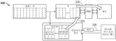
도 5 내지 도 7은 몇몇 실시예들에 따른, 리커버리 시퀀스의 부분을 예시하는 일련의 도이다. 도 5는 리커버리 시퀀스가 시작되기 전의 예시적인 시나리오를 설명하는 도(500)이다. 중재기(238)(도 2)와 같은 중재기는 메모리 인터페이스 큐(도 5의 "큐")에 배치하기 위한 커맨드 큐로부터 들어오는 커맨드들을 선택한다. 이 동작은 중재기에 의해 선택된 순서로 큐에 배치된 커맨드들을 도시하는 화살표(501)에 의해 도시되어 있다. 화살표(502)는 리플레이 큐에 배치되는 커맨드들의 사본을 도시한다. 화살표(503)는 PHY 계층 및 메모리 채널을 통해 DRAM 모듈에 대해 큐로부터 전송된 커맨드들을 도시한다.5-7 are a series of diagrams illustrating a portion of a recovery sequence, in accordance with some embodiments. 5 is a diagram 500 illustrating an exemplary scenario before a recovery sequence begins. An arbiter, such as arbiter 238 (FIG. 2) selects incoming commands from the command queue for placement in a memory interface queue ("queue" in FIG. 5). This operation is illustrated by
도 6은 에러 메시지가 커맨드 패리티 에러 또는 정정 불가능한 에러를 나타내는 ECC 또는 CRC 체크 에러와 같은 에러를 나타내고 있음을 나타내는 화살표(504)로 계속되는 도 5의 시나리오가 채널을 통해 발생했음을 보여주는 도(600)이다. 이는 위에서 논의된 바와 같이 리커버리 시퀀스가 시작되게 한다. 그 다음, 리플레이 큐로부터의 커맨드들은 큐에 추가된 리플레이 큐로부터의 커맨드들을 나타내는 화살표(505)에 의해 도시된 바와 같이 순서대로 리플레이된다. 그 다음, 이러한 커맨드들은 화살표(506)에 의해 표시된 바와 같이 채널을 통해 전송된다.FIG. 6 is a diagram 600 showing that the scenario of FIG. 5 has occurred over a channel, continuing with
도 7은 리커버리 시퀀스의 재시작을 요구하는 리커버리 시퀀스 동안 지정된 에러 조건이 발생한, 나중의 시나리오를 도시하는 도(700)이다. 재시작 시, 긴급한 리프레시 커맨드가 화살표(507)에 의해 표시된 바와 같이 전송되도록 존재한다. 재시작된 리커버리 시퀀스의 커맨드들이 전송되기 전에, 화살표(508)에 의해 예시된 바와 같이, 긴급한 리프레시 커맨드가 전송될 큐 내에 배치된다. 그 다음, 리플레이 큐의 커맨드들이 화살표(509)에 의해 표시된 바와 같이 전송을 위해 큐에 추가된다.FIG. 7 is a diagram 700 illustrating a later scenario in which a specified error condition occurs during the recovery sequence that requires restarting the recovery sequence. Upon restart, an urgent refresh command exists to be sent as indicated by
이 실시예에서는 에러 조건들이 재시작하기 위해 리커버리 시퀀스를 요구할 때 긴급한 리프레시 커맨드가 전송될 수 있지만, 다른 실시예들에서는 긴급한 리프레시 커맨드에 대한 체크(블록(412), 도 4)는 프로세스의 추가 지점들, 또는 프로세스의 다른 지점들에서 수행될 수 있다. 예를 들어, 체크는 리커버리 시퀀스의 시작 시에 발생할 수 있거나, 또는 리플레이 큐가 추가 체크를 보장할 만큼 충분히 큰 경우, 블록(420)과 같은 에러 조건이 없는 리커버리 시퀀스 동안 긴급한 리프레시에 대한 주기적 체크가 발생할 수 있다.While in this embodiment an urgent refresh command may be sent when error conditions require a recovery sequence to restart, in other embodiments the check for an urgent refresh command (block 412, FIG. 4) may be performed at additional points in the process. , or at other points in the process. For example, the check may occur at the start of the recovery sequence, or if the replay queue is large enough to warrant an additional check, periodic checks for an urgent refresh may occur during the recovery sequence without an error condition, such as
도 2의 메모리 컨트롤러(200), 또는 중재기(238) 및 리프레시 제어 회로(232)와 같은 그의 임의의 부분들은 프로그램에 의해 판독될 수 있고 집적 회로들을 제조하기 위해 직접적으로 또는 간접적으로 사용될 수 있는 데이터베이스 또는 다른 데이터 구조의 형태로 컴퓨터 액세스 가능 데이터 구조에 의해 설명되거나 표현될 수 있다. 예를 들어, 이러한 데이터 구조는 Verilog 또는 VHDL과 같은 고레벨 설계 언어(HDL)에서의 하드웨어 기능의 거동-레벨 설명 또는 레지스터-전송 레벨(RTL) 설명일 수 있다. 설명은 합성 라이브러리로부터 게이트들의 리스트를 포함하는 네트리스트를 생성하기 위해 설명을 합성할 수 있는 합성 도구에 의해 판독될 수 있다. 네트리스트는 집적 회로들을 포함하는 하드웨어의 기능을 또한 나타내는 게이트들의 세트를 포함한다. 이어서 네트리스트는 마스크들에 적용될 기하학적 형상들을 설명하는 데이터 세트를 생성하도록 배치 및 라우팅될 수 있다. 이어서 마스크들은 집적 회로들을 생성하기 위해 다양한 반도체 제조 단계들에서 사용될 수 있다. 대안적으로, 컴퓨터 액세스 가능 저장 매체 상의 데이터베이스는, 원하는 바에 따라, 네트리스트(합성 라이브러리를 갖거나 갖지 않음) 또는 데이터 세트, 또는 그래픽 데이터 시스템(GDS) II 데이터일 수 있다.The
특정 실시예들이 설명되었지만, 이러한 실시예들에 대한 다양한 수정들이 당업자에게 명백할 것이다. 예를 들어, 메모리 채널 컨트롤러(210) 및/또는 전력 엔진(250)의 내부 아키텍처는 상이한 실시예들에서 다를 수 있다. 메모리 컨트롤러(200)는 고대역폭 메모리(HBM), RAMbus DRAM(RDRAM) 등과 같은, DDRx 이외의 다른 유형들의 메모리에 인터페이스할 수 있다. 예시된 실시예는 별개의 DIMM들 또는 SIMM들에 대응하는 메모리의 각각의 랭크를 보여주었지만, 다른 실시예들에서 각각의 모듈은 다수의 랭크들을 지원할 수 있다. 또 다른 실시예들은 다른 유형들의 DRAM 모듈들 또는 특정 모듈에 포함되지 않는 DRAM들, 예를 들어 호스트 마더보드에 장착된 DRAM들을 포함할 수 있다. 따라서, 첨부된 청구항들에 의해 개시된 실시예들의 범위에 속하는 개시된 실시예들의 모든 수정들을 포함하는 것이 의도된다.Although specific embodiments have been described, various modifications to these embodiments will become apparent to those skilled in the art. For example, the internal architecture of
Claims (32)
Translated fromKorean적어도 하나의 동적 랜덤 액세스 메모리(DRAM)에 결합하도록 적응된 메모리 채널에 결합하기 위한 출력을 갖는 메모리 인터페이스 큐;
들어오는 메모리 커맨드들을 선택하고, 그들을 상기 메모리 인터페이스 큐에 배치하여 그들이 상기 메모리 채널을 통해 전송되게 하기 위해 상기 메모리 인터페이스 큐에 결합된 중재기; 및
상기 메모리 인터페이스 큐에 배치된 메모리 액세스 커맨드들을 저장하는 적어도 하나의 리플레이 큐; 및
상기 중재기에 결합되고, 상기 메모리 채널을 통해 메모리 영역에 전송된 활성화 커맨드들의 수를 카운트하는 활성화 카운터를 모니터링하고 상기 활성화 카운터가 지정된 임계치를 초과하는 것에 응답하여 긴급한 리프레시 커맨드가 전송되어야 함을 상기 중재기에 시그널링하도록 동작 가능한 리프레시 제어 회로; 및
지정된 유형의 에러가 발생했음을 검출하고, 상기 에러에 응답하여 상기 적어도 하나의 리플레이 큐로부터 선택된 메모리 커맨드들을 재전송하는 것을 포함하는 리커버리 시퀀스를 개시하기 위한 리플레이 제어 회로를 포함하는, 메모리 컨트롤러.As a memory controller,
a memory interface queue having an output for coupling to a memory channel adapted to couple to at least one dynamic random access memory (DRAM);
an arbiter coupled to the memory interface queue to select incoming memory commands and place them into the memory interface queue for transmission over the memory channel; and
at least one replay queue storing memory access commands disposed in the memory interface queue; and
monitoring an activation counter that is coupled to the arbiter and counts the number of activation commands sent to a memory region over the memory channel and that an urgent refresh command should be sent in response to the activation counter exceeding a specified threshold; a refresh control circuit operable to signal to the machine; and
and replay control circuitry for detecting that an error of a specified type has occurred and initiating a recovery sequence comprising retransmitting selected memory commands from the at least one replay queue in response to the error.
메모리 인터페이스 큐에 메모리 커맨드들을 선택적으로 배치하고, 상기 메모리 커맨드들을 상기 메모리 인터페이스 큐로부터 적어도 하나의 동적 랜덤 액세스 메모리(DRAM)에 결합된 메모리 채널로 전송하고, 상기 전송된 메모리 커맨드들의 사본을 리플레이 큐에 저장하는 단계;
상기 메모리 채널을 통해 상기 DRAM의 메모리 영역으로 전송된 활성화 커맨드들의 수를 카운트하는 단계;
지정된 임계 값 초과인 활성화 커맨드들의 수에 응답하여, 긴급한 리프레시 커맨드가 상기 메모리 영역으로 전송되어야 함을 중재기에 시그널링하는 단계;
지정된 유형의 에러가 발생했음을 검출하고, 상기 에러에 응답하여 상기 리플레이 큐로부터 선택된 메모리 커맨드들을 재전송하는 것을 포함하는 리커버리 시퀀스를 개시하는 단계; 및
상기 리커버리 시퀀스에서의 지정된 에러 조건들에 응답하여, 긴급한 리프레시 커맨드가 상기 중재기에서 보류 중인지를 체크하고, 만약 그렇다면, 상기 리커버리 시퀀스를 중단하고 상기 긴급한 리프레시 커맨드가 전송될 수 있도록 하는 단계를 포함하는, 방법.As a method,
selectively placing memory commands in a memory interface queue, transferring the memory commands from the memory interface queue to a memory channel coupled to at least one dynamic random access memory (DRAM), and copying the transmitted memory commands to a replay queue storing in;
counting the number of activation commands transmitted to a memory area of the DRAM through the memory channel;
in response to a number of activation commands exceeding a specified threshold, signaling to an arbiter that an urgent refresh command should be sent to the memory region;
detecting that an error of a specified type has occurred and initiating a recovery sequence comprising retransmitting selected memory commands from the replay queue in response to the error; and
In response to specified error conditions in the recovery sequence, checking if an urgent refresh command is pending in the arbiter and, if so, aborting the recovery sequence and allowing the urgent refresh command to be sent. , method.
데이터 프로세서;
상기 데이터 프로세서에 결합된 데이터 패브릭; 및
데이터 프로세서로부터의 메모리 요청들을 이행하기 위해 상기 데이터 패브릭에 결합된 메모리 컨트롤러를 포함하고, 상기 메모리 컨트롤러는,
적어도 하나의 동적 랜덤 액세스 메모리(DRAM)에 결합하도록 적응된 메모리 채널에 결합하기 위한 출력을 갖는 메모리 인터페이스 큐;
들어오는 메모리 커맨드들을 선택하고, 그들을 상기 메모리 인터페이스 큐에 배치하여 그들이 상기 메모리 채널을 통해 전송되게 하기 위해 상기 메모리 인터페이스 큐에 결합된 중재기; 및
상기 메모리 인터페이스 큐에 배치된 메모리 커맨드들을 저장하는 적어도 하나의 리플레이 큐; 및
상기 중재기에 결합되고, 상기 메모리 채널을 통해 메모리 영역에 전송된 활성화 커맨드들의 수를 카운트하는 활성화 카운터를 모니터링하고 상기 활성화 카운터가 지정된 임계치를 초과하는 것에 응답하여 긴급한 리프레시 커맨드가 전송되어야 함을 상기 중재기에 시그널링하도록 동작 가능한 리프레시 제어 회로; 및
지정된 유형의 에러가 발생했음을 검출하고, 상기 에러에 응답하여 상기 적어도 하나의 리플레이 큐로부터 선택된 메모리 커맨드들을 재전송하는 것을 포함하는 리커버리 시퀀스를 개시하기 위한 리플레이 제어 회로를 포함하는 것인, 데이터 처리 시스템.As a data processing system,
data processor;
a data fabric coupled to the data processor; and
a memory controller coupled to the data fabric for fulfilling memory requests from a data processor, the memory controller comprising:
a memory interface queue having an output for coupling to a memory channel adapted to couple to at least one dynamic random access memory (DRAM);
an arbiter coupled to the memory interface queue to select incoming memory commands and place them into the memory interface queue for transmission over the memory channel; and
at least one replay queue storing memory commands disposed in the memory interface queue; and
monitoring an activation counter that is coupled to the arbiter and counts the number of activation commands sent to a memory region over the memory channel and that an urgent refresh command should be sent in response to the activation counter exceeding a specified threshold; a refresh control circuit operable to signal to the machine; and
and replay control circuitry for detecting that an error of a specified type has occurred and for initiating a recovery sequence comprising retransmitting selected memory commands from said at least one replay queue in response to said error.
Applications Claiming Priority (3)
| Application Number | Priority Date | Filing Date | Title |
|---|---|---|---|
| US16/887,904US11561862B2 (en) | 2020-05-29 | 2020-05-29 | Refresh management for DRAM |
| US16/887,904 | 2020-05-29 | ||
| PCT/US2021/034068WO2021242766A1 (en) | 2020-05-29 | 2021-05-25 | Refresh management for dram |
Publications (1)
| Publication Number | Publication Date |
|---|---|
| KR20230017865Atrue KR20230017865A (en) | 2023-02-06 |
Family
ID=78706246
Family Applications (1)
| Application Number | Title | Priority Date | Filing Date |
|---|---|---|---|
| KR1020227046090APendingKR20230017865A (en) | 2020-05-29 | 2021-05-25 | Refresh management for DRAM |
Country Status (6)
| Country | Link |
|---|---|
| US (1) | US11561862B2 (en) |
| EP (1) | EP4158632A4 (en) |
| JP (1) | JP2023527981A (en) |
| KR (1) | KR20230017865A (en) |
| CN (1) | CN115668377A (en) |
| WO (1) | WO2021242766A1 (en) |
Families Citing this family (8)
| Publication number | Priority date | Publication date | Assignee | Title |
|---|---|---|---|---|
| US11809743B2 (en)* | 2020-09-21 | 2023-11-07 | Advanced Micro Devices, Inc. | Refresh management list for DRAM |
| KR20220062843A (en)* | 2020-11-09 | 2022-05-17 | 에스케이하이닉스 주식회사 | Storage device and operating method thereof |
| EP4487330A1 (en)* | 2022-03-24 | 2025-01-08 | Google LLC | Efficient dram refresh management using graded refresh alert levels |
| US12315546B2 (en) | 2022-04-29 | 2025-05-27 | Changxin Memory Technologies, Inc. | Signal control circuit, signal control method for blocking activation operations and semiconductor memory |
| TWI807919B (en)* | 2022-07-14 | 2023-07-01 | 群聯電子股份有限公司 | Data retry-read method, a memory storage device and a memory control circuit unit |
| US12094515B2 (en) | 2022-08-17 | 2024-09-17 | Qualcomm Incorporated | Dynamic random access memory (DRAM) row hammering mitigation |
| TWI859935B (en)* | 2023-06-17 | 2024-10-21 | 華邦電子股份有限公司 | Electronic device and control method for memory refresh operation thereof |
| CN119938146A (en)* | 2023-11-03 | 2025-05-06 | 腾讯科技(深圳)有限公司 | Chip including resend queue, computer device and method for processing resend instruction |
Family Cites Families (18)
| Publication number | Priority date | Publication date | Assignee | Title |
|---|---|---|---|---|
| US9236110B2 (en) | 2012-06-30 | 2016-01-12 | Intel Corporation | Row hammer refresh command |
| US9117544B2 (en) | 2012-06-30 | 2015-08-25 | Intel Corporation | Row hammer refresh command |
| KR20140028618A (en) | 2012-08-29 | 2014-03-10 | 삼성전자주식회사 | Memory device for reducimg write fail, system includinmg tha same, and method there-of |
| US9299400B2 (en) | 2012-09-28 | 2016-03-29 | Intel Corporation | Distributed row hammer tracking |
| US9281046B2 (en)* | 2013-10-08 | 2016-03-08 | Advanced Micro Devices, Inc. | Data processor with memory controller for high reliability operation and method |
| US9293188B2 (en) | 2014-02-03 | 2016-03-22 | Advanced Micro Devices, Inc. | Memory and memory controller for high reliability operation and method |
| US9812185B2 (en) | 2015-10-21 | 2017-11-07 | Invensas Corporation | DRAM adjacent row disturb mitigation |
| US10403333B2 (en) | 2016-07-15 | 2019-09-03 | Advanced Micro Devices, Inc. | Memory controller with flexible address decoding |
| EP3270295A1 (en)* | 2016-07-15 | 2018-01-17 | Advanced Micro Devices, Inc. | Memory controller with virtual controller mode |
| US11675659B2 (en) | 2016-07-15 | 2023-06-13 | Advanced Micro Devices, Inc. | DDR memory error recovery |
| KR102699088B1 (en)* | 2016-12-06 | 2024-08-26 | 삼성전자주식회사 | Memory system performing hammer refresh operation |
| FR3066842B1 (en) | 2017-05-24 | 2019-11-08 | Upmem | ROW HAMMER CORRECTION LOGIC FOR DRAM WITH INTEGRATED PROCESSOR |
| US10770168B2 (en)* | 2018-07-12 | 2020-09-08 | Micron Technology, Inc. | Memory sub-system with background scan and histogram statistics |
| CN110729006B (en)* | 2018-07-16 | 2022-07-05 | 超威半导体(上海)有限公司 | Refresh Schemes in Memory Controllers |
| US10901839B2 (en)* | 2018-09-26 | 2021-01-26 | International Business Machines Corporation | Common high and low random bit error correction logic |
| CN118197372A (en)* | 2018-10-09 | 2024-06-14 | 美光科技公司 | Method for row hammer mitigation and memory device and system employing the same |
| US10950288B2 (en) | 2019-03-29 | 2021-03-16 | Intel Corporation | Refresh command control for host assist of row hammer mitigation |
| US11222685B2 (en)* | 2020-05-15 | 2022-01-11 | Advanced Micro Devices, Inc. | Refresh management for DRAM |
- 2020
- 2020-05-29USUS16/887,904patent/US11561862B2/enactiveActive
- 2021
- 2021-05-25KRKR1020227046090Apatent/KR20230017865A/enactivePending
- 2021-05-25CNCN202180038845.8Apatent/CN115668377A/enactivePending
- 2021-05-25JPJP2022572471Apatent/JP2023527981A/enactivePending
- 2021-05-25WOPCT/US2021/034068patent/WO2021242766A1/ennot_activeCeased
- 2021-05-25EPEP21812685.2Apatent/EP4158632A4/enactivePending
Also Published As
| Publication number | Publication date |
|---|---|
| CN115668377A (en) | 2023-01-31 |
| EP4158632A1 (en) | 2023-04-05 |
| WO2021242766A1 (en) | 2021-12-02 |
| EP4158632A4 (en) | 2024-07-31 |
| US20210374006A1 (en) | 2021-12-02 |
| JP2023527981A (en) | 2023-07-03 |
| US11561862B2 (en) | 2023-01-24 |
Similar Documents
| Publication | Publication Date | Title |
|---|---|---|
| KR102615693B1 (en) | Refresh management for DRAM | |
| US11561862B2 (en) | Refresh management for DRAM | |
| KR20190019209A (en) | DDR memory error recovery | |
| US12141038B2 (en) | Error recovery for non-volatile memory modules | |
| KR102478527B1 (en) | Signaling for Heterogeneous Memory Systems | |
| KR102542493B1 (en) | Command Replay to Non-Volatile Dual Inline Memory Modules |
Legal Events
| Date | Code | Title | Description |
|---|---|---|---|
| PA0105 | International application | St.27 status event code:A-0-1-A10-A15-nap-PA0105 | |
| E13-X000 | Pre-grant limitation requested | St.27 status event code:A-2-3-E10-E13-lim-X000 | |
| P11-X000 | Amendment of application requested | St.27 status event code:A-2-2-P10-P11-nap-X000 | |
| P13-X000 | Application amended | St.27 status event code:A-2-2-P10-P13-nap-X000 | |
| PG1501 | Laying open of application | St.27 status event code:A-1-1-Q10-Q12-nap-PG1501 | |
| A201 | Request for examination | ||
| PA0201 | Request for examination | St.27 status event code:A-1-2-D10-D11-exm-PA0201 | |
| E902 | Notification of reason for refusal | ||
| PE0902 | Notice of grounds for rejection | St.27 status event code:A-1-2-D10-D21-exm-PE0902 | |
| P11-X000 | Amendment of application requested | St.27 status event code:A-2-2-P10-P11-nap-X000 |