KR20230016976A - Converter controller and controlling method - Google Patents
Converter controller and controlling methodDownload PDFInfo
- Publication number
- KR20230016976A KR20230016976AKR1020210098631AKR20210098631AKR20230016976AKR 20230016976 AKR20230016976 AKR 20230016976AKR 1020210098631 AKR1020210098631 AKR 1020210098631AKR 20210098631 AKR20210098631 AKR 20210098631AKR 20230016976 AKR20230016976 AKR 20230016976A
- Authority
- KR
- South Korea
- Prior art keywords
- voltage
- switching element
- duty
- battery
- converter
- Prior art date
- Legal status (The legal status is an assumption and is not a legal conclusion. Google has not performed a legal analysis and makes no representation as to the accuracy of the status listed.)
- Pending
Links
Images


Classifications
- B—PERFORMING OPERATIONS; TRANSPORTING
- B60—VEHICLES IN GENERAL
- B60L—PROPULSION OF ELECTRICALLY-PROPELLED VEHICLES; SUPPLYING ELECTRIC POWER FOR AUXILIARY EQUIPMENT OF ELECTRICALLY-PROPELLED VEHICLES; ELECTRODYNAMIC BRAKE SYSTEMS FOR VEHICLES IN GENERAL; MAGNETIC SUSPENSION OR LEVITATION FOR VEHICLES; MONITORING OPERATING VARIABLES OF ELECTRICALLY-PROPELLED VEHICLES; ELECTRIC SAFETY DEVICES FOR ELECTRICALLY-PROPELLED VEHICLES
- B60L53/00—Methods of charging batteries, specially adapted for electric vehicles; Charging stations or on-board charging equipment therefor; Exchange of energy storage elements in electric vehicles
- B60L53/20—Methods of charging batteries, specially adapted for electric vehicles; Charging stations or on-board charging equipment therefor; Exchange of energy storage elements in electric vehicles characterised by converters located in the vehicle
- B60L53/22—Constructional details or arrangements of charging converters specially adapted for charging electric vehicles
- H—ELECTRICITY
- H02—GENERATION; CONVERSION OR DISTRIBUTION OF ELECTRIC POWER
- H02M—APPARATUS FOR CONVERSION BETWEEN AC AND AC, BETWEEN AC AND DC, OR BETWEEN DC AND DC, AND FOR USE WITH MAINS OR SIMILAR POWER SUPPLY SYSTEMS; CONVERSION OF DC OR AC INPUT POWER INTO SURGE OUTPUT POWER; CONTROL OR REGULATION THEREOF
- H02M3/00—Conversion of DC power input into DC power output
- H02M3/02—Conversion of DC power input into DC power output without intermediate conversion into AC
- H02M3/04—Conversion of DC power input into DC power output without intermediate conversion into AC by static converters
- H02M3/10—Conversion of DC power input into DC power output without intermediate conversion into AC by static converters using discharge tubes with control electrode or semiconductor devices with control electrode
- H02M3/145—Conversion of DC power input into DC power output without intermediate conversion into AC by static converters using discharge tubes with control electrode or semiconductor devices with control electrode using devices of a triode or transistor type requiring continuous application of a control signal
- H02M3/155—Conversion of DC power input into DC power output without intermediate conversion into AC by static converters using discharge tubes with control electrode or semiconductor devices with control electrode using devices of a triode or transistor type requiring continuous application of a control signal using semiconductor devices only
- H02M3/156—Conversion of DC power input into DC power output without intermediate conversion into AC by static converters using discharge tubes with control electrode or semiconductor devices with control electrode using devices of a triode or transistor type requiring continuous application of a control signal using semiconductor devices only with automatic control of output voltage or current, e.g. switching regulators
- H02M3/158—Conversion of DC power input into DC power output without intermediate conversion into AC by static converters using discharge tubes with control electrode or semiconductor devices with control electrode using devices of a triode or transistor type requiring continuous application of a control signal using semiconductor devices only with automatic control of output voltage or current, e.g. switching regulators including plural semiconductor devices as final control devices for a single load
- B—PERFORMING OPERATIONS; TRANSPORTING
- B60—VEHICLES IN GENERAL
- B60L—PROPULSION OF ELECTRICALLY-PROPELLED VEHICLES; SUPPLYING ELECTRIC POWER FOR AUXILIARY EQUIPMENT OF ELECTRICALLY-PROPELLED VEHICLES; ELECTRODYNAMIC BRAKE SYSTEMS FOR VEHICLES IN GENERAL; MAGNETIC SUSPENSION OR LEVITATION FOR VEHICLES; MONITORING OPERATING VARIABLES OF ELECTRICALLY-PROPELLED VEHICLES; ELECTRIC SAFETY DEVICES FOR ELECTRICALLY-PROPELLED VEHICLES
- B60L53/00—Methods of charging batteries, specially adapted for electric vehicles; Charging stations or on-board charging equipment therefor; Exchange of energy storage elements in electric vehicles
- B60L53/20—Methods of charging batteries, specially adapted for electric vehicles; Charging stations or on-board charging equipment therefor; Exchange of energy storage elements in electric vehicles characterised by converters located in the vehicle
- B—PERFORMING OPERATIONS; TRANSPORTING
- B60—VEHICLES IN GENERAL
- B60L—PROPULSION OF ELECTRICALLY-PROPELLED VEHICLES; SUPPLYING ELECTRIC POWER FOR AUXILIARY EQUIPMENT OF ELECTRICALLY-PROPELLED VEHICLES; ELECTRODYNAMIC BRAKE SYSTEMS FOR VEHICLES IN GENERAL; MAGNETIC SUSPENSION OR LEVITATION FOR VEHICLES; MONITORING OPERATING VARIABLES OF ELECTRICALLY-PROPELLED VEHICLES; ELECTRIC SAFETY DEVICES FOR ELECTRICALLY-PROPELLED VEHICLES
- B60L53/00—Methods of charging batteries, specially adapted for electric vehicles; Charging stations or on-board charging equipment therefor; Exchange of energy storage elements in electric vehicles
- B60L53/50—Charging stations characterised by energy-storage or power-generation means
- B60L53/53—Batteries
- B—PERFORMING OPERATIONS; TRANSPORTING
- B60—VEHICLES IN GENERAL
- B60L—PROPULSION OF ELECTRICALLY-PROPELLED VEHICLES; SUPPLYING ELECTRIC POWER FOR AUXILIARY EQUIPMENT OF ELECTRICALLY-PROPELLED VEHICLES; ELECTRODYNAMIC BRAKE SYSTEMS FOR VEHICLES IN GENERAL; MAGNETIC SUSPENSION OR LEVITATION FOR VEHICLES; MONITORING OPERATING VARIABLES OF ELECTRICALLY-PROPELLED VEHICLES; ELECTRIC SAFETY DEVICES FOR ELECTRICALLY-PROPELLED VEHICLES
- B60L58/00—Methods or circuit arrangements for monitoring or controlling batteries or fuel cells, specially adapted for electric vehicles
- B60L58/10—Methods or circuit arrangements for monitoring or controlling batteries or fuel cells, specially adapted for electric vehicles for monitoring or controlling batteries
- B60L58/18—Methods or circuit arrangements for monitoring or controlling batteries or fuel cells, specially adapted for electric vehicles for monitoring or controlling batteries of two or more battery modules
- B60L58/19—Switching between serial connection and parallel connection of battery modules
- B—PERFORMING OPERATIONS; TRANSPORTING
- B60—VEHICLES IN GENERAL
- B60L—PROPULSION OF ELECTRICALLY-PROPELLED VEHICLES; SUPPLYING ELECTRIC POWER FOR AUXILIARY EQUIPMENT OF ELECTRICALLY-PROPELLED VEHICLES; ELECTRODYNAMIC BRAKE SYSTEMS FOR VEHICLES IN GENERAL; MAGNETIC SUSPENSION OR LEVITATION FOR VEHICLES; MONITORING OPERATING VARIABLES OF ELECTRICALLY-PROPELLED VEHICLES; ELECTRIC SAFETY DEVICES FOR ELECTRICALLY-PROPELLED VEHICLES
- B60L58/00—Methods or circuit arrangements for monitoring or controlling batteries or fuel cells, specially adapted for electric vehicles
- B60L58/10—Methods or circuit arrangements for monitoring or controlling batteries or fuel cells, specially adapted for electric vehicles for monitoring or controlling batteries
- B60L58/18—Methods or circuit arrangements for monitoring or controlling batteries or fuel cells, specially adapted for electric vehicles for monitoring or controlling batteries of two or more battery modules
- B60L58/20—Methods or circuit arrangements for monitoring or controlling batteries or fuel cells, specially adapted for electric vehicles for monitoring or controlling batteries of two or more battery modules having different nominal voltages
- H—ELECTRICITY
- H02—GENERATION; CONVERSION OR DISTRIBUTION OF ELECTRIC POWER
- H02J—CIRCUIT ARRANGEMENTS OR SYSTEMS FOR SUPPLYING OR DISTRIBUTING ELECTRIC POWER; SYSTEMS FOR STORING ELECTRIC ENERGY
- H02J7/00—Circuit arrangements for charging or depolarising batteries or for supplying loads from batteries
- H02J7/0013—Circuit arrangements for charging or depolarising batteries or for supplying loads from batteries acting upon several batteries simultaneously or sequentially
- H—ELECTRICITY
- H02—GENERATION; CONVERSION OR DISTRIBUTION OF ELECTRIC POWER
- H02J—CIRCUIT ARRANGEMENTS OR SYSTEMS FOR SUPPLYING OR DISTRIBUTING ELECTRIC POWER; SYSTEMS FOR STORING ELECTRIC ENERGY
- H02J7/00—Circuit arrangements for charging or depolarising batteries or for supplying loads from batteries
- H02J7/0047—Circuit arrangements for charging or depolarising batteries or for supplying loads from batteries with monitoring or indicating devices or circuits
- H—ELECTRICITY
- H02—GENERATION; CONVERSION OR DISTRIBUTION OF ELECTRIC POWER
- H02J—CIRCUIT ARRANGEMENTS OR SYSTEMS FOR SUPPLYING OR DISTRIBUTING ELECTRIC POWER; SYSTEMS FOR STORING ELECTRIC ENERGY
- H02J7/00—Circuit arrangements for charging or depolarising batteries or for supplying loads from batteries
- H02J7/007—Regulation of charging or discharging current or voltage
- H02J7/00712—Regulation of charging or discharging current or voltage the cycle being controlled or terminated in response to electric parameters
- H02J7/007182—Regulation of charging or discharging current or voltage the cycle being controlled or terminated in response to electric parameters in response to battery voltage
- H—ELECTRICITY
- H02—GENERATION; CONVERSION OR DISTRIBUTION OF ELECTRIC POWER
- H02J—CIRCUIT ARRANGEMENTS OR SYSTEMS FOR SUPPLYING OR DISTRIBUTING ELECTRIC POWER; SYSTEMS FOR STORING ELECTRIC ENERGY
- H02J7/00—Circuit arrangements for charging or depolarising batteries or for supplying loads from batteries
- H02J7/34—Parallel operation in networks using both storage and other DC sources, e.g. providing buffering
- H02J7/342—The other DC source being a battery actively interacting with the first one, i.e. battery to battery charging
- H—ELECTRICITY
- H02—GENERATION; CONVERSION OR DISTRIBUTION OF ELECTRIC POWER
- H02M—APPARATUS FOR CONVERSION BETWEEN AC AND AC, BETWEEN AC AND DC, OR BETWEEN DC AND DC, AND FOR USE WITH MAINS OR SIMILAR POWER SUPPLY SYSTEMS; CONVERSION OF DC OR AC INPUT POWER INTO SURGE OUTPUT POWER; CONTROL OR REGULATION THEREOF
- H02M1/00—Details of apparatus for conversion
- H02M1/08—Circuits specially adapted for the generation of control voltages for semiconductor devices incorporated in static converters
- B—PERFORMING OPERATIONS; TRANSPORTING
- B60—VEHICLES IN GENERAL
- B60L—PROPULSION OF ELECTRICALLY-PROPELLED VEHICLES; SUPPLYING ELECTRIC POWER FOR AUXILIARY EQUIPMENT OF ELECTRICALLY-PROPELLED VEHICLES; ELECTRODYNAMIC BRAKE SYSTEMS FOR VEHICLES IN GENERAL; MAGNETIC SUSPENSION OR LEVITATION FOR VEHICLES; MONITORING OPERATING VARIABLES OF ELECTRICALLY-PROPELLED VEHICLES; ELECTRIC SAFETY DEVICES FOR ELECTRICALLY-PROPELLED VEHICLES
- B60L2210/00—Converter types
- B60L2210/10—DC to DC converters
- B60L2210/12—Buck converters
- B—PERFORMING OPERATIONS; TRANSPORTING
- B60—VEHICLES IN GENERAL
- B60L—PROPULSION OF ELECTRICALLY-PROPELLED VEHICLES; SUPPLYING ELECTRIC POWER FOR AUXILIARY EQUIPMENT OF ELECTRICALLY-PROPELLED VEHICLES; ELECTRODYNAMIC BRAKE SYSTEMS FOR VEHICLES IN GENERAL; MAGNETIC SUSPENSION OR LEVITATION FOR VEHICLES; MONITORING OPERATING VARIABLES OF ELECTRICALLY-PROPELLED VEHICLES; ELECTRIC SAFETY DEVICES FOR ELECTRICALLY-PROPELLED VEHICLES
- B60L2240/00—Control parameters of input or output; Target parameters
- B60L2240/40—Drive Train control parameters
- B60L2240/54—Drive Train control parameters related to batteries
- B60L2240/547—Voltage
- B—PERFORMING OPERATIONS; TRANSPORTING
- B60—VEHICLES IN GENERAL
- B60Y—INDEXING SCHEME RELATING TO ASPECTS CROSS-CUTTING VEHICLE TECHNOLOGY
- B60Y2200/00—Type of vehicle
- B60Y2200/90—Vehicles comprising electric prime movers
- B60Y2200/91—Electric vehicles
- H—ELECTRICITY
- H02—GENERATION; CONVERSION OR DISTRIBUTION OF ELECTRIC POWER
- H02J—CIRCUIT ARRANGEMENTS OR SYSTEMS FOR SUPPLYING OR DISTRIBUTING ELECTRIC POWER; SYSTEMS FOR STORING ELECTRIC ENERGY
- H02J2207/00—Indexing scheme relating to details of circuit arrangements for charging or depolarising batteries or for supplying loads from batteries
- H02J2207/20—Charging or discharging characterised by the power electronics converter
- H—ELECTRICITY
- H02—GENERATION; CONVERSION OR DISTRIBUTION OF ELECTRIC POWER
- H02J—CIRCUIT ARRANGEMENTS OR SYSTEMS FOR SUPPLYING OR DISTRIBUTING ELECTRIC POWER; SYSTEMS FOR STORING ELECTRIC ENERGY
- H02J2310/00—The network for supplying or distributing electric power characterised by its spatial reach or by the load
- H02J2310/40—The network being an on-board power network, i.e. within a vehicle
- H02J2310/48—The network being an on-board power network, i.e. within a vehicle for electric vehicles [EV] or hybrid vehicles [HEV]
- H—ELECTRICITY
- H02—GENERATION; CONVERSION OR DISTRIBUTION OF ELECTRIC POWER
- H02M—APPARATUS FOR CONVERSION BETWEEN AC AND AC, BETWEEN AC AND DC, OR BETWEEN DC AND DC, AND FOR USE WITH MAINS OR SIMILAR POWER SUPPLY SYSTEMS; CONVERSION OF DC OR AC INPUT POWER INTO SURGE OUTPUT POWER; CONTROL OR REGULATION THEREOF
- H02M1/00—Details of apparatus for conversion
- H02M1/10—Arrangements incorporating converting means for enabling loads to be operated at will from different kinds of power supplies, e.g. from AC or DC
- H—ELECTRICITY
- H02—GENERATION; CONVERSION OR DISTRIBUTION OF ELECTRIC POWER
- H02M—APPARATUS FOR CONVERSION BETWEEN AC AND AC, BETWEEN AC AND DC, OR BETWEEN DC AND DC, AND FOR USE WITH MAINS OR SIMILAR POWER SUPPLY SYSTEMS; CONVERSION OF DC OR AC INPUT POWER INTO SURGE OUTPUT POWER; CONTROL OR REGULATION THEREOF
- H02M3/00—Conversion of DC power input into DC power output
- H02M3/02—Conversion of DC power input into DC power output without intermediate conversion into AC
- H02M3/04—Conversion of DC power input into DC power output without intermediate conversion into AC by static converters
- H02M3/10—Conversion of DC power input into DC power output without intermediate conversion into AC by static converters using discharge tubes with control electrode or semiconductor devices with control electrode
- H02M3/145—Conversion of DC power input into DC power output without intermediate conversion into AC by static converters using discharge tubes with control electrode or semiconductor devices with control electrode using devices of a triode or transistor type requiring continuous application of a control signal
- H02M3/155—Conversion of DC power input into DC power output without intermediate conversion into AC by static converters using discharge tubes with control electrode or semiconductor devices with control electrode using devices of a triode or transistor type requiring continuous application of a control signal using semiconductor devices only
- H02M3/156—Conversion of DC power input into DC power output without intermediate conversion into AC by static converters using discharge tubes with control electrode or semiconductor devices with control electrode using devices of a triode or transistor type requiring continuous application of a control signal using semiconductor devices only with automatic control of output voltage or current, e.g. switching regulators
- H02M3/158—Conversion of DC power input into DC power output without intermediate conversion into AC by static converters using discharge tubes with control electrode or semiconductor devices with control electrode using devices of a triode or transistor type requiring continuous application of a control signal using semiconductor devices only with automatic control of output voltage or current, e.g. switching regulators including plural semiconductor devices as final control devices for a single load
- H02M3/1582—Buck-boost converters
- Y—GENERAL TAGGING OF NEW TECHNOLOGICAL DEVELOPMENTS; GENERAL TAGGING OF CROSS-SECTIONAL TECHNOLOGIES SPANNING OVER SEVERAL SECTIONS OF THE IPC; TECHNICAL SUBJECTS COVERED BY FORMER USPC CROSS-REFERENCE ART COLLECTIONS [XRACs] AND DIGESTS
- Y02—TECHNOLOGIES OR APPLICATIONS FOR MITIGATION OR ADAPTATION AGAINST CLIMATE CHANGE
- Y02T—CLIMATE CHANGE MITIGATION TECHNOLOGIES RELATED TO TRANSPORTATION
- Y02T10/00—Road transport of goods or passengers
- Y02T10/60—Other road transportation technologies with climate change mitigation effect
- Y02T10/70—Energy storage systems for electromobility, e.g. batteries
- Y—GENERAL TAGGING OF NEW TECHNOLOGICAL DEVELOPMENTS; GENERAL TAGGING OF CROSS-SECTIONAL TECHNOLOGIES SPANNING OVER SEVERAL SECTIONS OF THE IPC; TECHNICAL SUBJECTS COVERED BY FORMER USPC CROSS-REFERENCE ART COLLECTIONS [XRACs] AND DIGESTS
- Y02—TECHNOLOGIES OR APPLICATIONS FOR MITIGATION OR ADAPTATION AGAINST CLIMATE CHANGE
- Y02T—CLIMATE CHANGE MITIGATION TECHNOLOGIES RELATED TO TRANSPORTATION
- Y02T10/00—Road transport of goods or passengers
- Y02T10/60—Other road transportation technologies with climate change mitigation effect
- Y02T10/7072—Electromobility specific charging systems or methods for batteries, ultracapacitors, supercapacitors or double-layer capacitors
- Y—GENERAL TAGGING OF NEW TECHNOLOGICAL DEVELOPMENTS; GENERAL TAGGING OF CROSS-SECTIONAL TECHNOLOGIES SPANNING OVER SEVERAL SECTIONS OF THE IPC; TECHNICAL SUBJECTS COVERED BY FORMER USPC CROSS-REFERENCE ART COLLECTIONS [XRACs] AND DIGESTS
- Y02—TECHNOLOGIES OR APPLICATIONS FOR MITIGATION OR ADAPTATION AGAINST CLIMATE CHANGE
- Y02T—CLIMATE CHANGE MITIGATION TECHNOLOGIES RELATED TO TRANSPORTATION
- Y02T90/00—Enabling technologies or technologies with a potential or indirect contribution to GHG emissions mitigation
- Y02T90/10—Technologies relating to charging of electric vehicles
- Y02T90/14—Plug-in electric vehicles
Landscapes
- Engineering & Computer Science (AREA)
- Power Engineering (AREA)
- Transportation (AREA)
- Mechanical Engineering (AREA)
- Life Sciences & Earth Sciences (AREA)
- Sustainable Development (AREA)
- Sustainable Energy (AREA)
- Dc-Dc Converters (AREA)
Abstract
Description
Translated fromKorean본 발명은 컨버터 제어장치 및 제어방법에 관한 것으로, 더 상세하게는 모빌리티를 구동하는 주배터리에 전원을 공급하는 다른 배터리를 연결함에 있어서, 다른 배터리의 수에 맞는 스위칭 소자와 컨버터를 주 배터리와 각각 연결하여 전원을 공급하는게 아니라 컨버터의 입력단에 스위칭 소자를 추가 연결함으로써 해당 패키지를 간소화시켜 효율을 향상시킬 수 있는 컨버터 제어장치 및 제어방법에 관한 것이다.The present invention relates to a converter control device and control method, and more particularly, in connecting another battery that supplies power to a main battery driving mobility, a switching element and a converter suitable for the number of other batteries are connected to the main battery, respectively. It relates to a converter control device and control method capable of improving efficiency by simplifying a corresponding package by additionally connecting a switching element to an input terminal of a converter rather than supplying power by connecting the converter.
차량을 포함하는 모빌리티는 배러티의 출력을 통해 구동될 수 있다. 그러한 모빌리티의 주행을 위해서 고전압 배터리의 충전을 위한 상용 AC 전원을 이용한 충전기(OBC : On Board Charger)가 차량 내부에 장착된다. OBC는 일반적으로 상용 AC 전원의 역률을 보정하는 PFC회로부와 링크 커패시터 전압에서 배터리가 요구하는 전압으로 변환하는 DC/DC컨버터로 구성된다. 그러한 배터리는 단독으로 구동하면 용량이 급격히 늘어나고, 이는 모빌리티의 무게를 상승시켜 연비를 낮추고 배터리 원가가 상승한다. 이러한 과제를 해결하는 방안으로 1개 또는 복수개의 교대형 배터리(Swappable Battery)가 OBC보다 선제적으로 메인 배터리를 충전하는 구성이 있다. 이러한 교대형 배터리를 활용하면 주 배터리(Main Battery)의 용량을 줄여 원가 절감이 가능하고, 주행거리 및 모터/인버터 출력도 증대시킬 수 있다.Mobility including vehicles may be driven through the output of the variety. In order to drive such mobility, a charger (OBC: On Board Charger) using commercial AC power for charging a high-voltage battery is mounted inside the vehicle. OBC generally consists of a PFC circuit that corrects the power factor of commercial AC power and a DC/DC converter that converts the link capacitor voltage into the voltage required by the battery. The capacity of such a battery increases rapidly when driven alone, which increases the weight of the mobility, lowers fuel efficiency, and increases the cost of the battery. As a way to solve this problem, there is a configuration in which one or a plurality of swappable batteries preemptively charge the main battery rather than the OBC. When such a replaceable battery is used, cost can be reduced by reducing the capacity of the main battery, and the mileage and output of the motor/inverter can be increased.
주 배터리와 교대형 배터리들 각각은 같은 최대전압을 가질 수 있으나, 배터리 충전량(SOC: Status of Charge)에 따라 유동적인 범위의 전압을 가지고 있다. 따라서, 이들을 단순 단락 구조로 연결하면 전압차로 인한 화재와 부품 소손의 위험이 있다. 그러므로, 교대형 배터리로 주 배터리를 충전하는데 사용하기 위해서는 일반적으로 교대형 배터리 하나당 하나의 DCDC컨버터가 추가로 필요하고, 이는 비용과 사이즈를 증가시키고, 효율을 떨어뜨린다. 따라서, 이를 개선할 컨버터 제어장치가 요구된다.Each of the main battery and the alternate batteries may have the same maximum voltage, but have a voltage in a flexible range according to the state of charge (SOC) of the battery. Therefore, if they are connected in a simple short-circuit structure, there is a risk of fire and component damage due to a voltage difference. Therefore, in order to use the alternating battery to charge the main battery, one additional DCDC converter per alternating battery is generally required, which increases cost and size, and reduces efficiency. Therefore, a converter control device to improve this is required.
상기 배경기술로서 설명된 사항들은 본 발명의 배경에 대한 이해 증진을 위한 것일 뿐, 이 기술분야에서 통상의 지식을 가진자에게 이미 알려진 종래기술에 해당함을 인정하는 것으로 받아들여져서는 안 될 것이다.The matters described as the background art are only for improving understanding of the background of the present invention, and should not be taken as an admission that they correspond to prior art already known to those skilled in the art.
본 발명은 위 문제점을 해결하기 위하여 제안된 것으로서, 모빌리티를 구동하는 주배터리에 전원을 공급하는 다른 배터리를 연결함에 있어서, 다른 배터리의 수에 맞는 스위칭 소자와 컨버터를 주 배터리와 각각 연결하여 전원을 공급하는게 아니라 컨버터의 입력단에 스위칭 소자를 추가 연결함으로써 해당 패키지를 간소화시켜 효율을 향상시킬 수 있는 컨버터 제어장치 및 제어방법을 제공하고자 함이다.The present invention has been proposed to solve the above problems, and in connecting other batteries that supply power to a main battery driving mobility, switching elements and converters suitable for the number of other batteries are connected to the main battery to supply power. It is not to supply, but to provide a converter control device and control method that can improve efficiency by simplifying the package by additionally connecting a switching element to the input terminal of the converter.
본 발명에 따른 컨버터 제어장치는, 적어도 하나의 제1 배터리의 일단마다 대응되어 접속되는 각각의 제1 스위칭 소자; 제1 배터리의 타단이 접속되고 제1 스위칭 소자와 서로 직렬 접속되는 제2 스위칭 소자; 제2 배터리의 일단이 접속되는 제3 스위칭 소자; 제2 배터리의 타단이 접속되고 제3 스위칭 소자와 서로 직렬 접속되는 제4 스위칭 소자; 제1 스위칭 소자 및 제2 스위칭 소자 사이인 제1 노드와 제3 스위칭 소자 및 제4 스위칭 소자의 사이인 제2노드 사이에 접속되는 인덕터; 및 제1 배터리의 일단마다의 전압값인 각각의 제1 전압 및 제2 배터리의 일단의 전압값인 제2 전압을 입력받고, 제1 전압과 제2 전압을 기반으로 각각의 제1 스위칭 소자의 듀티를 도출는 듀티 제어부를 포함한다.A converter control apparatus according to the present invention includes: first switching elements connected to each other corresponding to one end of at least one first battery; a second switching element connected to the other end of the first battery and connected in series with the first switching element; a third switching element to which one end of the second battery is connected; a fourth switching element connected to the other end of the second battery and connected in series with the third switching element; an inductor connected between a first node between the first switching element and the second switching element and a second node between the third switching element and the fourth switching element; and each first voltage, which is the voltage value of each end of the first battery, and the second voltage, which is the voltage value of each end of the second battery. A duty control unit for deriving the duty is included.
듀티 제어부는 일정시간 동안의 제2 전압의 평균을 입력받고, 제1 전압과 제2 전압의 평균을 기반으로 각각의 제1 스위칭 소자의 듀티를 도출할 수 있다.The duty control unit may receive an average of the second voltages for a predetermined period of time and derive a duty of each first switching element based on the average of the first voltage and the second voltage.
제1 배터리와 제1 스위칭 소자는 복수이고, 제1 스위칭 소자는 그 서로 간에 제1 스위칭 소자의 일단과 제1 노드 사이인 제3 노드에서 접속되고, 각각의 제1 배터리의 일단과 각각의 제1 스위칭 소자의 사이에 제1배터리의 일단에서 제1 스위칭소자 방향의 일방향 도통을 수행하는 스위치를 더 포함할 수 있다.The first battery and the first switching element are plural, the first switching elements are connected to each other at a third node that is between one end of the first switching element and the first node, and one end of each first battery and one end of each first switching element are connected to each other. A switch for conducting unidirectional conduction from one end of the first battery toward the first switching element may be further included between one switching element.
듀티 제어부는 각각의 제1 전압이 제2 전압보다 모두 낮은 경우 듀티를 도출하지 않을 수 있다.The duty controller may not derive a duty when each first voltage is lower than the second voltage.
듀티 제어부는 각 제1 전압 중 적어도 어느 하나가 제2 전압보다 높은 경우 듀티를 도출할 수 있다.The duty controller may derive a duty when at least one of the first voltages is higher than the second voltage.
듀티 제어부는 제1 전압과 각각의 스위칭 소자의 듀티로 도출되는 제1노드의 전압값인 제3전압과 제2 전압이 같아지도록 각각의 제1 스위칭 소자의 듀티를 도출할 수 있다.The duty control unit may derive the duty of each first switching element such that the third voltage, which is a voltage value of the first node derived from the first voltage and the duty of each switching element, is equal to the second voltage.
듀티 제어부는 수학식 1을 통하여 제1 스위칭 소자의 듀티를 도출할 수 있다.The duty controller may derive the duty of the first switching element through
[수학식 1][Equation 1]

(여기서, Vk는 각각의 제1 전압, Vs1k는 각각의 제1스위칭소자의 듀티, VB2는 제2전압)(Here, Vk is each first voltage, Vs1k is the duty of each first switching element, and VB2 is the second voltage)
듀티 제어부는 제1 전압과 제2 전압을 기반으로 벅 모드로 동작하도록 각각의 제1 스위칭 소자의 듀티를 도출할 수 있다.The duty control unit may derive a duty of each first switching element to operate in a buck mode based on the first voltage and the second voltage.
본 발명에 따른 컨버터 제어방법은, 적어도 하나의 제1 배터리의 전압을 변환하여 제2 배터리로 전달하는 컨버터를 제어하는 방법에 있어서, 전압 측정기에서 제1 배터리의 일단마다의 전압값인 각각의 제1 전압 및 제2 배터리의 일단의 전압값인 제2 전압을 측정하는 단계; 및 듀티 제어부에서 측정한 제1 전압과 제2 전압을 기반으로 제1배터리의 일단마다 대응되어 접속되는 각각의 제1 스위칭 소자의 듀티를 도출하는 단계를 포함한다.A converter control method according to the present invention is a method for controlling a converter that converts the voltage of at least one first battery and transfers the converted voltage to a second battery, wherein each voltage value of each end of the first battery is measured in a voltage meter. measuring the first voltage and the second voltage, which is a voltage value of one end of the second battery; and deriving a duty of each first switching element connected to one end of the first battery based on the first voltage and the second voltage measured by the duty control unit.
듀티를 도출하는 단계는,The step of deriving the duty is,
복수인 제1 스위칭 소자는 그 서로 간에 제1 스위칭 소자의 일단과 제1 노드 사이인 제3 노드에서 접속되고,The plurality of first switching elements are connected to each other at a third node between one end of the first switching element and the first node,
복수인 제1배터리로서 각각의 제1 배터리의 일단과 각각의 제1 스위칭 소자의 사이의 스위치가 제1배터리의 일단에서 제1 스위칭소자 방향의 일방향 도통을 수행할 수 있다.As a plurality of first batteries, a switch between one end of each first battery and each first switching element may perform unidirectional conduction from one end of the first battery toward the first switching element.
듀티를 도출하는 단계는,The step of deriving the duty is,
각각의 제1 전압이 제2 전압보다 모두 낮은 경우 듀티를 도출하지 않을 수 있다.When all of the first voltages are lower than the second voltages, the duty may not be derived.
듀티를 도출하는 단계는,The step of deriving the duty is,
각 제1 전압 중 적어도 어느 하나가 제2 전압보다 높은 경우 듀티를 도출할 수 있다.When at least one of the first voltages is higher than the second voltage, a duty may be derived.
듀티를 도출하는 단계는,The step of deriving the duty is,
제1 전압과 각각의 스위칭 소자의 듀티로 도출되는 제1노드의 전압값인 제3전압과 제2 전압이 같아지도록 각각의 제1 스위칭 소자의 듀티를 도출할 수 있다.The duty of each first switching element may be derived such that the third voltage, which is a voltage value of the first node derived from the first voltage and the duty of each switching element, is equal to the second voltage.
듀티를 도출하는 단계는,The step of deriving the duty is,
수학식 1을 통하여 제1 스위칭 소자의 듀티를 도출할 수 있다.The duty of the first switching element may be derived through
[수학식 1][Equation 1]

(여기서, Vk는 각각의 제1 전압, Vs1k는 각각의 제1 스위칭소자의 듀티, VB2는 제2 전압)(Here, Vk is each first voltage, Vs1k is the duty of each first switching element, and VB2 is the second voltage)
듀티를 도출하는 단계는, 제1 전압과 제2 전압을 기반으로 벅 모드로 동작하도록 각각의 제1 스위칭 소자의 듀티를 도출할 수 있다.The deriving of the duty may include deriving a duty of each first switching element to operate in a buck mode based on the first voltage and the second voltage.
본 발명의 컨버터 제어장치 및 제어방법에 따르면, 모빌리티를 구동하는 주배터리에 전원을 공급하는 다른 배터리를 연결함에 있어서, 다른 배터리의 수에 맞는 스위칭 소자와 컨버터를 주 배터리와 각각 연결하여 전원을 공급하는게 아니라 컨버터의 입력단에 스위칭 소자를 추가 연결함으로써 해당 패키지를 간소화시켜 효율을 향상시킬 수 있다.According to the converter control apparatus and control method of the present invention, in connecting other batteries that supply power to the main battery driving mobility, switching elements and converters suitable for the number of other batteries are connected to the main battery to supply power. Instead, it is possible to simplify the package and improve efficiency by additionally connecting a switching element to the input terminal of the converter.
도 1은 본 발명의 일 실시예에 따른 컨버터 제어장치를 나타낸 구성도.
도 2 내지 도 3은 본 발명의 일 실시예에 따른 컨버터 제어장치를 나타낸 도면.
도 4는 본 발명의 일 실시예에 따른 컨버터 제어장치의 작동 결과 및 제어방법을 나타낸 그래프.1 is a configuration diagram showing a converter control device according to an embodiment of the present invention.
2 and 3 are diagrams illustrating a converter control device according to an embodiment of the present invention.
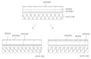
Figure 4 is a graph showing the operation result and control method of the converter control device according to an embodiment of the present invention.
본 명세서 또는 출원에 개시되어 있는 본 발명의 실시 예들에 대해서 특정한 구조적 내지 기능적 설명들은 단지 본 발명에 따른 실시 예를 설명하기 위한 목적으로 예시된 것으로, 본 발명에 따른 실시 예들은 다양한 형태로 실시될 수 있으며 본 명세서 또는 출원에 설명된 실시 예들에 한정되는 것으로 해석되어서는 아니 된다. 이하, 본 발명의 실시예를 첨부도면을 참조로 상세하게 설명하기로 한다.Specific structural or functional descriptions of the embodiments of the present invention disclosed in this specification or application are merely exemplified for the purpose of explaining the embodiments according to the present invention, and the embodiments according to the present invention may be implemented in various forms. and should not be construed as being limited to the embodiments described in this specification or application. Hereinafter, embodiments of the present invention will be described in detail with reference to the accompanying drawings.
도 1은 본 발명의 일 실시예에 따른 컨버터 제어장치를 나타낸 구성도이고,도 2 내지 도 3은 본 발명의 일 실시예에 따른 컨버터 제어장치를 나타낸 도면이고, 도 4는 본 발명의 일 실시예에 따른 컨버터 제어장치의 작동 결과 및 제어방법을 나타낸 그래프이다.1 is a configuration diagram showing a converter control device according to an embodiment of the present invention, FIGS. 2 to 3 are diagrams showing a converter control device according to an embodiment of the present invention, and FIG. 4 is an embodiment of the present invention. It is a graph showing the operation result and control method of the converter control device according to the example.
도 1은 본 발명의 일 실시예에 따른 컨버터 제어장치를 나타낸 구성도이다. 본 발명의 일 실시예에 따른 컨버터 제어장치는 제2 배터리(B2)에 전력을 공급하는 적어도 하나의 제1 배터리(B1k)의 일단마다 대응되어 접속되는 각각의 제1 스위칭 소자(S11,S13);를 포함하는 컨버터, 제1배터리의 전압인 제1전압과 제2배터리의 전압인 제2전압을 측정하는 제1전압측정기(M1) 및 제2전압측정기(M2)를 포함하는 전압측정기(M), 제1 스위칭 소자(S11,S13)의 듀티를 제어하는 듀티 제어부(D)로 구성된다.1 is a configuration diagram showing a converter control device according to an embodiment of the present invention. The converter control device according to an embodiment of the present invention includes first switching elements S11 and S13 connected to each other corresponding to one end of at least one first battery B1k that supplies power to the second battery B2. A voltage measuring device (M) including a converter including ; and a first voltage measuring device (M1) and a second voltage measuring device (M2) measuring a first voltage, which is the voltage of the first battery, and a second voltage, which is the voltage of the second battery. ), and a duty controller D for controlling the duty of the first switching elements S11 and S13.
도 1의 본 발명의 일 실시예에 따른 컨버터 제어장치는 복수의 배터리로 다른 배터리를 충전하는 시스템에 필요한 장치이다. 도 1에서 전압측정기(M)는 제2전압과 입력 전압을 구성하는 적어도 하나의 제1전압을 입력받아 듀티 제어부(D)에 전달한다. 듀티제어부(D)는 제1전압 및 제2전압, 특히 둘 사이의 차를 기반으로 듀티를 제어하는 것이다.The converter control device according to one embodiment of the present invention of FIG. 1 is a device necessary for a system for charging other batteries with a plurality of batteries. In FIG. 1 , the voltage meter M receives at least one first voltage constituting the second voltage and the input voltage and transmits it to the duty control unit D. The duty control unit D controls the duty based on the first voltage and the second voltage, in particular, a difference between the two.
도 2는 본 발명의 일 실시예에 따른 컨버터 제어장치를 나타낸 도면이고, 본 발명의 일 실시예에 따른 컨버터 제어장치는 적어도 하나의 제1 배터리(B1k)의 일단마다 대응되어 접속되는 각각의 제1 스위칭 소자(S11,S13); 제1 배터리의 타단이 접속되고 제1 스위칭 소자와 서로 직렬 접속되는 제2 스위칭 소자(S2); 제2 배터리의 일단이 접속되는 제3 스위칭 소자(S3); 제2 배터리의 타단이 접속되고 제3 스위칭 소자와 서로 직렬 접속되는 제4 스위칭 소자(S4); 제1 스위칭 소자 및 제2 스위칭 소자 사이인 제1 노드와 제3 스위칭 소자 및 제4 스위칭 소자의 사이인 제2노드 사이에 접속되는 인덕터(I); 및 제1 배터리의 일단마다의 전압값인 각각의 제1 전압 및 제2 배터리의 일단의 전압값인 제2 전압을 입력받고, 제1 전압과 제2 전압을 기반으로 각각의 제1 스위칭 소자의 듀티를 도출하는 듀티 제어부(D);를 포함한다.2 is a diagram showing a converter control device according to an embodiment of the present invention, and the converter control device according to an embodiment of the present invention corresponds to and connects each end of at least one first battery B1k. 1 switching element (S11, S13); a second switching element (S2) connected to the other end of the first battery and connected in series with the first switching element; a third switching element (S3) to which one end of the second battery is connected; a fourth switching element (S4) connected to the other end of the second battery and connected in series with the third switching element; an inductor (I) connected between a first node between the first switching element and the second switching element and a second node between the third switching element and the fourth switching element; and each first voltage, which is the voltage value of each end of the first battery, and the second voltage, which is the voltage value of each end of the second battery. A duty control unit (D) for deriving a duty; includes.
본 발명의 일 실시예에 따른 컨버터 제어장치는 DC-DC 컨버터에 관한 제어장치를 포함한다. 특히 본 발명의 일 실시예는 제1 스위칭 소자 내지 제4 스위칭 소자(S1k,S2,S3,S4)를 포함하는 DC-DC 컨버터에 관한 제어장치이다. 컨버터로서 전력을 변환하기 위해 인덕터가 제1노드와 제2 노드사이에 접속될 수 있다.A converter control device according to an embodiment of the present invention includes a control device related to a DC-DC converter. In particular, one embodiment of the present invention is a control device for a DC-DC converter including first to fourth switching elements (S1k, S2, S3, and S4). An inductor may be connected between the first node and the second node to convert power as a converter.
여기서 제1배터리 측의 스위칭 소자인 제1 스위칭 소자 및 제2 스위칭소자, 그리고 제2배터리 측의 스위칭소자인 제3 스위칭소자 및 제4 스위칭소자는 다이오드(쇼트키 등) 및 트렌지스터(MOSFET 등)로 구성되는 비동기식 또는 교대로 스위칭하는 트렌지스터 및 동기식 DC-DC 컨버터일 수 있다. 특히 동기식 DC-DC 컨버터는 교차 스위칭을 막기 위해 스위칭 장치의 듀티를 제어하는 듀티 제어부(D)를 포함할 수 있다.Here, the first switching element and the second switching element, which are the switching elements of the first battery, and the third switching element and the fourth switching element, which are the switching elements of the second battery, are diodes (Schottky, etc.) and transistors (MOSFET, etc.) It may be an asynchronous or alternatingly switching transistor and a synchronous DC-DC converter consisting of In particular, the synchronous DC-DC converter may include a duty controller D for controlling the duty of the switching device to prevent cross-switching.
기존 컨버터 제어장치로서 전기자동차에 장착되는 컨버터는 모터의 구동출력을 생성하는 배터리와 같은 고전압 배터리를 충전하기 위한 컨버터일 수 있다. 다만, 전기자동차의 제2배터리(B2)를 충전하는 OBC(On Board Charger)에 포함된 컨버터는 충전하고자 하는 고전압 배터리인 제2 배터리(B2)에 교류전원으로부터 직접 출력을 공급할 수 있다. 한편, OBC는 제2 배터리에 전력을 공급하는 커패시터 또는 제1배터리(B1k)를 포함할 수 있다.A converter installed in an electric vehicle as a conventional converter control device may be a converter for charging a high-voltage battery such as a battery that generates a driving output of a motor. However, a converter included in an OBC (On Board Charger) for charging the second battery B2 of the electric vehicle may directly supply output from AC power to the second battery B2, which is a high voltage battery to be charged. Meanwhile, the OBC may include a capacitor or a first battery B1k that supplies power to the second battery.
이러한 경우, 제1배터리(B1k)와 제2배터리(B2)는 원칙적으로 전압 공급의 안정성상 동일한 수준의 전압을 공급받거나 공급하는 것으로 설계되어 있을 것이다. 이 때, 배터리는 충전상태(SOC)와 충방전횟수에 따른 열화상태(SOH)에 따라 전압이 일정수준 낮아지거나 높아질 수 있다. 따라서, 제1배터리(B1k)와 제2배터리(B2)를 단순히 연결하는 것은 단락 구조로서 부품 손상과 화재 위험 등을 초래하다. 또한, 이로 인해 제2배터리(B2)가 모터에 불안정한 전압을 공급하면 모터가 오동작, 과동작하거나 모터 특성이 열화되는 현상도 야기될 수 있다. 따라서, 배터리 간 전원을 공급하는 장치에는 반드시 벅-부스터 컨버터인 DC-DC 컨버터를 필요로 하였다.In this case, in principle, the first battery B1k and the second battery B2 may be designed to receive or supply the same level of voltage for stability of voltage supply. At this time, the voltage of the battery may be lowered or increased to a certain level according to the state of charge (SOC) and the state of deterioration (SOH) according to the number of charge/discharge cycles. Therefore, simply connecting the first battery B1k and the second battery B2 causes damage to components and a risk of fire as a short-circuit structure. In addition, when the second battery B2 supplies an unstable voltage to the motor, the motor may malfunction or over-operate, or the motor characteristics may be deteriorated. Therefore, a DC-DC converter, which is a buck-booster converter, is required for a device that supplies power between batteries.
그런데, 기존 발명은 제1배터리에 대응되는 벅 부스트 컨버터를 추가로 필요하므로, 제1배터리의 수를 늘릴때마다 이에 대응되는 벅 부스트 컨버터를 제2배터리 측, 즉 출력단에 연결하였다. 이에 따라, 기존 발명에서는 벅 부수트 컨버터에 포함되는 스위치와 인덕터의 개수가 산술적으로 증가한다. 그러므로, 기존 발명은 제1배터리의 수를 늘릴 때마다 중량이 늘어나고 배터리와 차량 구동의 효율이 감소되는 문제점이 있었다.However, since the existing invention additionally requires a buck boost converter corresponding to the first battery, whenever the number of first batteries is increased, a corresponding buck boost converter is connected to the second battery side, that is, to the output terminal. Accordingly, in the conventional invention, the number of switches and inductors included in the buck boot converter increases arithmetically. Therefore, the existing invention has a problem in that the weight increases whenever the number of first batteries is increased and the efficiency of driving the battery and the vehicle decreases.
특히, 본 발명의 일 실시예는 1개 이상의 제1배터리와 제2배터리를 연결하는 컨버터에서 제1배터리에 대응되는 제1 스위칭 소자의 듀티를 제1 전압과 제2 전압을 기반으로 도출함으로써 전력 변환을 제어한다. 즉, 본 발명의 일 실시예는 각각의 제1배터리의 제1전압과 제2배터리의 제2 전압 사이의 전압 차를 고려하여 듀티를 조절함으로써 전압차에 따른 단락 현상을 방지한다.In particular, one embodiment of the present invention derives the duty of the first switching element corresponding to the first battery in a converter connecting one or more first batteries and the second battery based on the first voltage and the second voltage, thereby generating electric power. control the conversion. That is, according to an embodiment of the present invention, a short circuit phenomenon due to a voltage difference is prevented by adjusting the duty considering the voltage difference between the first voltage of each first battery and the second voltage of the second battery.
그리고, 본 발명의 일 실시예는 제1 배터리의 수가 늘어남에도 불구하고 스위치와 인덕터의 개수를 크게 늘리지 않고 제1 스위칭 소자만 대응되게 추가한다. 따라서, 이에 따른 제2배터리를 충전하는 패키지의 용량과 중량을 간소화할 수 있어 출력밀도를 높이고, 가격경쟁력을 높인다. 또한, 본 발명의 일 실시예는 스위칭 소자의 전체적인 감소는 제2배터리를 통해 구동되는 차량 시스템 전체의 효율도 높일 수 있다.In addition, according to an embodiment of the present invention, only the first switching elements are added correspondingly without significantly increasing the number of switches and inductors despite the increase in the number of first batteries. Accordingly, the capacity and weight of the package for charging the second battery can be simplified, thereby increasing power density and price competitiveness. In addition, according to one embodiment of the present invention, overall efficiency of a vehicle system driven by the second battery can be increased by reducing the number of switching elements.
또한, 본 발명의 일 실시예의 듀티 제어부는 일정시간 동안의 제2 전압의 평균을 입력받고, 제1 전압과 제2 전압의 평균을 기반으로 각각의 제1 스위칭 소자의 듀티를 도출할 수 있다. 앞서 설명한 바와 같이, 배터리의 전압은 사전 설정되어 설계되어 있으나, 충전량과 열화상태에 따라 유동적이다. 여기서 평균은 특히 측정 직전 일정시간 동안 의 이동평균 또는 일정 구간 동안의 누적 전압의 평균이 바람직하다. 이와 같은 제2 전압을 대표하는 값과 제1 전압을 기반으로 제1스위칭소자의 듀티를 제어함으로써 본 발명의 일 실시예는 안정적인 전압 확보가 가능하다.In addition, the duty control unit according to an embodiment of the present invention may receive an average of the second voltages for a predetermined time, and derive a duty of each first switching element based on the average of the first voltage and the second voltage. As described above, the voltage of the battery is preset and designed, but is flexible according to the amount of charge and deterioration state. Here, the average is preferably a moving average for a certain period immediately before measurement or an average of accumulated voltages for a certain period. By controlling the duty of the first switching element based on the value representing the second voltage and the first voltage, it is possible to secure a stable voltage in one embodiment of the present invention.
도 2는 본 발명의 일 실시예에 따른 컨버터 제어장치를 나타낸 도면이고, 제1 배터리와 제1 스위칭 소자는 복수이고, 제1 스위칭 소자는 그 서로 간에 제1 스위칭 소자의 일단과 제1 노드 사이인 제3 노드에서 접속되고, 각각의 제1 배터리의 일단과 각각의 제1 스위칭 소자의 사이에 제1배터리의 일단에서 제1 스위칭소자 방향의 일방향 도통을 수행하는 스위치를 더 포함할 수 있다.2 is a diagram showing a converter control device according to an embodiment of the present invention, a first battery and a first switching element are plural, and the first switching element is between one end of the first switching element and the first node. The switch may further include a switch connected at the third node and performing one-way conduction from one end of the first battery to the first switching element between one end of each first battery and each first switching element.
기존 발명은 추가되는 제1배터리를 제2배터리에 연결함에 있어서, 출력 측인 제2배터리의 출력단, 즉 제3 스위칭소자와 제2배터리의 일단 사이의 제4노드 및 제4 스위칭소자와 제2배터리의 타단 사이의 제5노드에 연결하였다. 이에 따라, 기존 발명은 스위치의 수, 특히 인덕터의 수도 늘리는 문제점을 초래했다. 이러한 문제점을 해겨하기 위하여 본 발명의 일 실시예에서 제1스위칭 소자는 기존의 스위칭 소자(S11,S13)에 제1배터리가 늘어날때마다 추가되는 스위치(S12,S13)를 포함한다. 이에 따라, 본 발명의 일 실시예는 추가되는 스위치를 포함하는 제1스위칭소자를 제3노드에 접속함으로써 제2 배터리 측에 접속함으로써 더 추가되는 스위치와 인덕터의 수를 줄인다. 그리고, 본 발명의 일 실시예는 제1배터리의 일단에서 제1 스위칭소자 방향의 일방향 도통을 수행함에 따라, 각각의 제1스위칭 소자의 각 듀티에 따라 스위칭 온 되는 전압과 스위칭 오프되는 전압의 합으로서 입력전압이 결정되므로, 벅 컨버터의 단일 모드로서의 효율성도 갖는다.In the existing invention, in connecting the added first battery to the second battery, the output terminal of the second battery, that is, the fourth node between the third switching element and one end of the second battery, and the fourth switching element and the second battery It was connected to the fifth node between the other ends of. Accordingly, the existing invention has caused a problem of increasing the number of switches, in particular, the number of inductors. In order to overcome this problem, in one embodiment of the present invention, the first switching element includes switches S12 and S13 added to the existing switching elements S11 and S13 whenever the first battery increases. Accordingly, in one embodiment of the present invention, the number of additional switches and inductors is reduced by connecting the first switching device including the added switch to the third node and thereby connecting the second battery side. Further, in one embodiment of the present invention, as one end of the first battery performs one-way conduction in the direction of the first switching element, the sum of the voltage switched on and the voltage switched off according to each duty of each first switching element. Since the input voltage is determined as , it also has the efficiency as a single mode of a buck converter.
도 3은 본 발명의 일 실시예에 따른 컨버터 제어장치를 나타낸 도면이고, 듀티 제어부(D)는 각각의 제1 전압이 제2 전압보다 모두 낮은 경우 듀티를 도출하지 않을 수 있다. 또한, 듀티 제어부(D)는 각 제1 전압 중 적어도 어느 하나가 제2 전압보다 높은 경우 듀티를 도출할 수 있다. 그리고. 듀티 제어부(D)는 제1 전압과 각각의 스위칭 소자의 듀티로 도출되는 제1노드의 전압값인 제3전압과 제2 전압이 같아지도록 각각의 제1 스위칭 소자의 듀티를 도출할 수 있다.3 is a diagram showing a converter control device according to an embodiment of the present invention, and the duty controller D may not derive a duty when each first voltage is lower than the second voltage. Also, the duty controller D may derive a duty when at least one of the first voltages is higher than the second voltage. and. The duty control unit D may derive the duty of each first switching element so that the third voltage, which is the voltage value of the first node derived from the first voltage and the duty of each switching element, is equal to the second voltage.
[수학식 1][Equation 1]

여기서, Vk는 각각의 제1 전압, Vs1k는 각각의 제1스위칭소자의 듀티, VB2는 제2전압이다.Here, Vk is each first voltage, Vs1k is the duty of each first switching element, and VB2 is the second voltage.
제1전압은 일종의 병렬로 연결된 각각의 제1배터리의 전압으로, 제2배터리를 충전하는 관점에서 그 입력전압을 결정하는 변수들이다. 그리고, 이러한 변수를 바탕으로 도출되는 각 스위칭 소자의 각 듀티에 따라 최종적으로 입력전압이 결정된다. 따라서, 본 발명의 일 실시예는 벅-부스트 컨버터를 포함하나, 제1전압과 제2전압의 크기 비교에 따라 벅 모드, 부스트 모드, 벅-부스트 모드로 모두 구현될 수 있다. 다만, 단일 모드가 효율이나 회로 동작 면에서 가장 좋을 것이다. 특히, 본 발명의 일 실시예는 각각의 제1스위칭 소자의 각 듀티에 따라 스위칭 온 되는 전압과 스위칭 오프되는 전압의 합으로서 입력전압이 결정될 수 있으므로, 벅 모드로 구현되는 것이 좋을 것이다. 따라서, 본 발명의 일 실시예는 제1전압이 제2전압보다 모두 낮은 경우를 제외하거나, 제1전압을 강압하는 경우만을 포함하거나, 제3전압(입력전압의 개념)과 동일하게 맞추는 제어를 통해, 벅-부스트 모드를 포함한 다양한 모드로 구현됨으로써 발생되는 비효율성을 줄인다.The first voltage is a kind of voltage of each first battery connected in parallel, and is a variable that determines the input voltage in terms of charging the second battery. And, the input voltage is finally determined according to each duty of each switching element derived based on these variables. Accordingly, an embodiment of the present invention includes a buck-boost converter, but may be implemented in a buck mode, a boost mode, or a buck-boost mode according to a size comparison between the first voltage and the second voltage. However, single mode will be the best in terms of efficiency or circuit operation. In particular, in one embodiment of the present invention, since the input voltage can be determined as the sum of the switched-on voltage and the switched-off voltage according to each duty of each first switching element, it is preferable to implement the buck mode. Therefore, one embodiment of the present invention excludes the case where the first voltage is lower than the second voltage, includes only the case of stepping down the first voltage, or controls the same as the third voltage (concept of input voltage). Through this, inefficiency caused by implementation in various modes including buck-boost mode is reduced.
도 4는 본 발명의 일 실시예에 따른 컨버터 제어장치의 작동 결과 및 제어방법을 나타낸 그래프이고, 듀티 제어부(D)는 수학식 1을 통하여 제1 스위칭 소자의 듀티를 도출할 수 있다. 또한, 듀티 제어부(D)는 제1 전압과 제2 전압을 기반으로 벅 모드로 동작하도록 각각의 제1 스위칭 소자(S11,S13)의 듀티를 도출할 수 있다. 4 is a graph showing an operation result and a control method of a converter control device according to an embodiment of the present invention, and the duty controller D may derive the duty of the first switching element through
도 4에서 이하 첫번래 그림부터 세번째 그림까지 공통적으로 설명한다. 맨위 그래프의 가로축은 시간, 세로축은 제1배터리가 2이라고 가정하고, 각 제1전압인 입력전압1과 입력전아12, 그리고 제2전압을 측정한 값으로 나타낸 그래프이다. 그 아래 그래프의 가로축은 시간, 세로축은 인덕터(I)의 전류를 나타낸 그래프이다. 여기서 듀티는 수학식1을 통하여 도출하였고, 듀티는 각 스위칭 소자의 듀티의 합이 1이 되도록 설정하였다.In FIG. 4, the first to the third pictures will be commonly described below. Assuming that the first battery is 2, the horizontal axis of the top graph is time, and the vertical axis is a graph showing the measured values of
이에 따라, 도 4의 첫번째 그림과 같이 제2전압이 각 제1전압의 중간 정도로 설정된 경우 각 듀티가 동일하거나 비슷한 값으로 도출되어 제어될 것이다. 여기서 도 4의 두번째 그림은 제2전압이 감소하는 경우의 듀티 제어, 세번째 그림은 제2전압이 증가하는 경우의 듀티제어를 나타낸다. 도 4의 두번째 그림이나 세번째 그림과 같이 제2전압이 제1전압의 최솟값 또는 최댓값과 가깝게 설정된 경우 한쪽 배터리의 듀티가 높은 것으로 치우쳐지는 방향으로 도출되어 제어될 것이다. 그러나, 공통적으로 제1전압의 최댓값보다 강압되는 벅 단일 모드로서 본 발명의 일 실시예는 동작한 것이다. 이와 같이, 본 발명의 일 실시예에 따른 컨버터 제어장치는 제2전압이 유동적인 상황에서도 제1 스위칭소자의 각 듀티를 도출하여 수학식 1 또는 벅모드에 따라 제어하여 스위칭 소자의 동작 전압을 안정적으로 확보한다.Accordingly, as shown in the first figure of FIG. 4, when the second voltage is set to an intermediate level of each first voltage, each duty will be derived and controlled at the same or similar value. Here, the second figure of FIG. 4 shows duty control when the second voltage decreases, and the third figure shows duty control when the second voltage increases. If the second voltage is set close to the minimum or maximum value of the first voltage, as shown in the second or third figure of FIG. 4, the duty of one battery will be derived and controlled in a direction biased toward a high one. However, in common, one embodiment of the present invention operates as a buck single mode that is stepped down more than the maximum value of the first voltage. As such, the converter control device according to an embodiment of the present invention derives each duty of the first switching element even in a situation where the second voltage is fluctuating and controls it according to
여기서 스위칭소자는 BJT, SCR(Silicon Controlled Rectifier), TRIAC, UJT(Unijunction Transistor), PUT(Programmable Unijuunction Transister), JFET(Junction Field Effect Transistor), GTO(Gate Turn Off Thyrister), MCT(MOS Controlled Thyrister), IEGT(Injection-Enhanced Gate Transistor), IGBT(Integrated Gate Bipolar Transistor) IGCT(Integrated Gate Commutated Thyrister) MOSFET, IPD(Intelligent Power Device: 반도체 스위치)를 포함한다. 스위치는 스위칭소자 및 메커니컬 퓨즈, 메커니컬 릴레이, 다이오드 소자 등의 스위칭 소자 및 저항 소자 중 어느 하나에 해당할 수 있다. 또한, 여기서 컨버터는 DC-DC 컨버터로, 특히 고효율 및 고출력을 위하여 스위칭 소자는 다이오드가 아닌 교대로 스위칭 하는 4개의 트렌지스터가 사용되는 동기식 컨버터 일 수 있다.Here, the switching elements are BJT, SCR (Silicon Controlled Rectifier), TRIAC, UJT (Unijunction Transistor), PUT (Programmable Unijuunction Transistor), JFET (Junction Field Effect Transistor), GTO (Gate Turn Off Thyrister), MCT (MOS Controlled Thyrister) , IEGT (Injection-Enhanced Gate Transistor), IGBT (Integrated Gate Bipolar Transistor) IGCT (Integrated Gate Commutated Thyrister) MOSFET, IPD (Intelligent Power Device: Semiconductor Switch). The switch may correspond to any one of a switching element and a resistance element, such as a switching element, a mechanical fuse, a mechanical relay, and a diode element. In addition, here, the converter is a DC-DC converter, and in particular, for high efficiency and high output, the switching element may be a synchronous converter in which four transistors that alternately switch instead of diodes are used.
본 발명에 따른 컨버터 제어방법은, 적어도 하나의 제1 배터리의 전압을 변환하여 제2 배터리로 전달하는 컨버터를 제어하는 방법에 있어서, 전압 측정기에서 제1 배터리의 일단마다의 전압값인 각각의 제1 전압 및 제2 배터리의 일단의 전압값인 제2 전압을 측정하는 단계; 및 듀티 제어부에서 측정한 제1 전압과 제2 전압을 기반으로 제1배터리의 일단마다 대응되어 접속되는 각각의 제1 스위칭 소자의 듀티를 도출하는 단계를 포함한다.A converter control method according to the present invention is a method for controlling a converter that converts the voltage of at least one first battery and transfers the converted voltage to a second battery, wherein each voltage value of each end of the first battery is measured in a voltage meter. measuring the first voltage and the second voltage, which is a voltage value of one end of the second battery; and deriving a duty of each first switching element connected to one end of the first battery based on the first voltage and the second voltage measured by the duty control unit.
듀티를 도출하는 단계는, 복수인 제1 스위칭 소자는 그 서로 간에 제1 스위칭 소자의 일단과 제1 노드 사이인 제3 노드에서 접속되고, 복수인 제1배터리로서 각각의 제1 배터리의 일단과 각각의 제1 스위칭 소자의 사이의 스위치가 제1배터리의 일단에서 제1 스위칭소자 방향의 일방향 도통을 수행할 수 있다. 또한, 각각의 제1 전압이 제2 전압보다 모두 낮은 경우 듀티를 도출하지 않을 수 있다. 그리고, 각 제1 전압 중 적어도 어느 하나가 제2 전압보다 높은 경우 듀티를 도출할 수 있다. 다음으로, 듀티를 도출하는 단계는, 제1 전압과 각각의 스위칭 소자의 듀티로 도출되는 제1노드의 전압값인 제3전압과 제2 전압이 같아지도록 각각의 제1 스위칭 소자의 듀티를 도출할 수 있다. 끝으로, 듀티를 도출하는 단계는, 수학식 1을 통하여 제1 스위칭 소자의 듀티를 도출할 수 있다. 마지막으로, 듀티를 도출하는 단계는, 제1 전압과 제2 전압을 기반으로 벅 모드로 동작하도록 각각의 제1 스위칭 소자의 듀티를 도출할 수 있다.In the step of deriving the duty, a plurality of first switching elements are connected to each other at a third node between one end of the first switching element and the first node, and as a plurality of first batteries, one end of each first battery and A switch between each of the first switching elements may perform one-way conduction from one end of the first battery toward the first switching element. In addition, when all of the first voltages are lower than the second voltages, the duty may not be derived. In addition, when at least one of the first voltages is higher than the second voltage, a duty may be derived. Next, in the step of deriving the duty, the duty of each first switching element is derived such that the third voltage, which is the voltage value of the first node derived from the duty of the first voltage and each switching element, and the second voltage are equal. can do. Finally, in the step of deriving the duty, the duty of the first switching element may be derived through
본 발명의 일 실시예에 따른 컨버터 제어장치 및 제어방법은 모빌리티를 구동하는 주배터리에 전원을 공급하는 다른 배터리를 연결하는 컨버터에 관한 제어장치 및 제어방법에 관한 것이다. 기존 발명은 다른 배터리의 증가에 따라 벅 부수트 컨버터에 포함되는 스위치와 인덕터의 개수가 산술적으로 증가한다. 그러므로, 기존 발명은 제1배터리의 수를 늘릴 때마다 중량이 늘어나고 배터리와 차량 구동의 효율이 감소되는 문제점이 있었다. A converter control device and control method according to an embodiment of the present invention relates to a control device and control method related to a converter that connects another battery that supplies power to a main battery driving mobility. In the existing invention, the number of switches and inductors included in the buck boot converter increases arithmetically as the number of other batteries increases. Therefore, the existing invention has a problem in that the weight increases whenever the number of first batteries is increased and the efficiency of driving the battery and the vehicle decreases.
특히, 본 발명의 일 실시예는 1개 이상의 제1배터리와 제2배터리를 연결하는 컨버터에서 제1배터리에 대응되는 제1 스위칭 소자의 듀티를 제1 전압과 제2 전압을 기반으로 도출함으로써 전력 변환을 제어한다. 따라서, 이에 따른 제2배터리를 충전하는 패키지의 용량과 중량을 간소화할 수 있어 출력밀도를 높이고, 가격경쟁력을 높이며, 더 나아가 배터리로 구동하는 차량 시스템 전체의 효율도 높일 수 있다.In particular, one embodiment of the present invention derives the duty of the first switching element corresponding to the first battery in a converter connecting one or more first batteries and the second battery based on the first voltage and the second voltage, thereby generating electric power. control the conversion. Accordingly, it is possible to simplify the capacity and weight of the package for charging the second battery, thereby increasing power density, increasing price competitiveness, and further increasing the efficiency of the entire vehicle system driven by the battery.
발명의 특정한 실시예에 관련하여 도시하고 설명하였지만, 이하의 특허청구범위에 의해 제공되는 본 발명의 기술적 사상을 벗어나지 않는 한도 내에서, 본 발명이 다양하게 개량 및 변화될 수 있다는 것은 당 업계에서 통상의 지식을 가진 자에게 있어서 자명할 것이다. Although shown and described in relation to specific embodiments of the invention, it is common in the art that the present invention can be variously improved and changed without departing from the technical spirit of the present invention provided by the claims below. It will be self-evident to those who have knowledge of
B1k: 제1 배터리
B2: 제2 배터리
D: 듀티 제어부
I: 인덕터
M1(M11,M12): 제1전압 측정기
M2 제2전압 측정기
N1: 제1노드
N2: 제2노드
N3: 제3노드
S1k: 제1 스위칭소자
S12,S14: 스위치
S2: 제2 스위칭소자
S3: 제3 스위칭소자
S4: 제4 스위칭소자B1k: 1st battery
B2: Second battery
D: duty control
I: inductor
M1 (M11, M12): 1st voltage meter
M2 2nd voltage meter
N1: first node
N2: second node
N3: third node
S1k: first switching element
S12,S14: switch
S2: second switching element
S3: third switching element
S4: 4th switching element
Claims (15)
Translated fromKorean제1 스위칭 소자 및 제2 스위칭 소자 사이인 제1 노드와 제3 스위칭 소자 및 제4 스위칭 소자의 사이인 제2노드 사이에 접속되는 인덕터; 및
제1 배터리의 일단마다의 전압값인 각각의 제1 전압 및 제2 배터리의 일단의 전압값인 제2 전압을 입력받고, 제1 전압과 제2 전압을 기반으로 각각의 제1 스위칭 소자의 듀티를 도출하는 듀티 제어부;를 포함하는 컨버터 제어장치.Each first switching element connected to one end of at least one first battery in correspondence with each other; a second switching element connected to the other end of the first battery and connected in series with the first switching element; a third switching element to which one end of the second battery is connected; a fourth switching element connected to the other end of the second battery and connected in series with the third switching element;
an inductor connected between a first node between the first switching element and the second switching element and a second node between the third switching element and the fourth switching element; and
Each first voltage, which is the voltage value of each end of the first battery, and the second voltage, which is the voltage value of each end of the second battery, are input, and the duty of each first switching element is determined based on the first voltage and the second voltage. A converter control device including a; duty control unit that derives.
듀티 제어부는 일정시간 동안의 제2 전압의 평균을 입력받고, 제1 전압과 제2 전압의 평균을 기반으로 각각의 제1 스위칭 소자의 듀티를 도출하는 것을 특징으로 하는 컨버터 제어장치.The method of claim 1,
The duty control unit receives an average of the second voltage for a predetermined time, and derives a duty of each first switching element based on the average of the first voltage and the second voltage.
제1 배터리와 제1 스위칭 소자는 복수이고,
각각의 제1 배터리의 일단과 각각의 제1 스위칭 소자의 사이에 제1배터리의 일단에서 제1 스위칭소자 방향의 일방향 도통을 수행하는 스위치를 더 포함하는 것을 특징으로 하는 컨버터 제어장치.The method of claim 1,
The first battery and the first switching element are plural,
The converter control apparatus further comprising a switch for performing unidirectional conduction from one end of the first battery to the first switching element between one end of each first battery and each first switching element.
듀티 제어부는 각각의 제1 전압이 제2 전압보다 모두 낮은 경우 듀티를 도출하지 않는 것을 특징으로 하는 컨버터 제어장치.The method of claim 1,
The duty control unit does not derive a duty when each first voltage is lower than the second voltage.
듀티 제어부는 각 제1 전압 중 적어도 어느 하나가 제2 전압보다 높은 경우 듀티를 도출하는 것을 특징으로 하는 컨버터 제어장치.The method of claim 1,
The duty control unit derives a duty when at least one of the first voltages is higher than the second voltage.
듀티 제어부는 제1 전압과 각각의 스위칭 소자의 듀티로 도출되는 제1노드의 전압값인 제3전압과 제2 전압이 같아지도록 각각의 제1 스위칭 소자의 듀티를 도출하는 것을 특징으로 하는 컨버터 제어장치.The method of claim 1,
The duty control unit derives the duty of each first switching element so that the third voltage and the second voltage, which are the voltage values of the first node derived from the first voltage and the duty of each switching element, are equal to the converter control. Device.
듀티 제어부는 수학식 1을 통하여 제1 스위칭 소자의 듀티를 도출하는 것을 특징으로 하는 컨버터 제어장치.
[수학식 1]

(여기서, Vk는 각각의 제1 전압, Vs1k는 각각의 제1스위칭소자의 듀티, VB2는 제2전압)The method of claim 1,
The duty control unit derives the duty of the first switching element through Equation 1, characterized in that the converter control device.
[Equation 1]
(Here, Vk is each first voltage, Vs1k is the duty of each first switching element, and VB2 is the second voltage)
듀티 제어부는 제1 전압과 제2 전압을 기반으로 벅 모드로 동작하도록 각각의 제1 스위칭 소자의 듀티를 도출하는 것을 특징으로 하는 컨버터 제어장치.The method of claim 1,
The duty control unit derives a duty of each first switching element to operate in a buck mode based on the first voltage and the second voltage.
전압 측정기에서 제1 배터리의 일단마다의 전압값인 각각의 제1 전압 및 제2 배터리의 일단의 전압값인 제2 전압을 측정하는 단계; 및
듀티 제어부에서 측정한 제1 전압과 제2 전압을 기반으로 제1배터리의 일단마다 대응되어 접속되는 각각의 제1 스위칭 소자의 듀티를 도출하는 단계를 포함하는 컨버터 제어방법.A method for controlling a converter that converts a voltage of at least one first battery and transfers the converted voltage to a second battery,
measuring each first voltage, which is a voltage value of each end of a first battery, and a second voltage, which is a voltage value of one end of a second battery, with a voltage meter; and
A converter control method comprising deriving a duty of each first switching element connected to one end of a first battery based on a first voltage and a second voltage measured by a duty control unit.
듀티를 도출하는 단계는,
복수인 제1 스위칭 소자는 그 서로 간에 제1 스위칭 소자의 일단과 제1 노드 사이인 제3 노드에서 접속되고,
복수인 제1배터리로서 각각의 제1 배터리의 일단과 각각의 제1 스위칭 소자의 사이의 스위치가 제1배터리의 일단에서 제1 스위칭소자 방향의 일방향 도통을 수행하는 것을 특징으로 하는 컨버터 제어방법.The method of claim 9,
The step of deriving the duty is,
The plurality of first switching elements are connected to each other at a third node between one end of the first switching element and the first node,
A converter control method comprising a plurality of first batteries, wherein a switch between one end of each first battery and each first switching element performs one-way conduction from one end of the first battery toward the first switching element.
듀티를 도출하는 단계는,
각각의 제1 전압이 제2 전압보다 모두 낮은 경우 듀티를 도출하지 않는 것을 특징으로 하는 컨버터 제어방법.The method of claim 9,
The step of deriving the duty is,
Converter control method characterized in that the duty is not derived when each of the first voltage is lower than the second voltage.
듀티를 도출하는 단계는,
각 제1 전압 중 적어도 어느 하나가 제2 전압보다 높은 경우 듀티를 도출하는 것을 특징으로 하는 컨버터 제어방법.The method of claim 9,
The step of deriving the duty is,
A converter control method comprising deriving a duty when at least one of the first voltages is higher than the second voltage.
듀티를 도출하는 단계는,
제1 전압과 각각의 스위칭 소자의 듀티로 도출되는 제1노드의 전압값인 제3전압과 제2 전압이 같아지도록 각각의 제1 스위칭 소자의 듀티를 도출하는 것을 특징으로 하는 컨버터 제어방법.The method of claim 9,
The step of deriving the duty is,
A converter control method comprising deriving a duty of each first switching element such that a third voltage, which is a voltage value of the first node derived from the first voltage and the duty of each switching element, and the second voltage are equal.
듀티를 도출하는 단계는,
수학식 1을 통하여 제1 스위칭 소자의 듀티를 도출하는 것을 특징으로 하는 컨버터 제어방법.
[수학식 1]

(여기서, Vk는 각각의 제1 전압, Vs1k는 각각의 제1 스위칭소자의 듀티, VB2는 제2 전압)The method of claim 9,
The step of deriving the duty is,
A converter control method characterized in that the duty of the first switching element is derived through Equation 1.
[Equation 1]
(Here, Vk is each first voltage, Vs1k is the duty of each first switching element, and VB2 is the second voltage)
듀티를 도출하는 단계는,
제1 전압과 제2 전압을 기반으로 벅 모드로 동작하도록 각각의 제1 스위칭 소자의 듀티를 도출하는 것을 특징으로 하는 컨버터 제어방법.
The method of claim 9,
The step of deriving the duty is,
A converter control method comprising deriving a duty of each first switching element to operate in a buck mode based on the first voltage and the second voltage.
Priority Applications (4)
| Application Number | Priority Date | Filing Date | Title |
|---|---|---|---|
| KR1020210098631AKR20230016976A (en) | 2021-07-27 | 2021-07-27 | Converter controller and controlling method |
| US17/696,206US12388366B2 (en) | 2021-07-27 | 2022-03-16 | Converter control device and controlling method |
| DE102022108927.4ADE102022108927A1 (en) | 2021-07-27 | 2022-04-12 | CONVERTER CONTROL DEVICE AND CONTROL METHOD |
| CN202210388460.0ACN115694182A (en) | 2021-07-27 | 2022-04-14 | Converter control device and control method |
Applications Claiming Priority (1)
| Application Number | Priority Date | Filing Date | Title |
|---|---|---|---|
| KR1020210098631AKR20230016976A (en) | 2021-07-27 | 2021-07-27 | Converter controller and controlling method |
Publications (1)
| Publication Number | Publication Date |
|---|---|
| KR20230016976Atrue KR20230016976A (en) | 2023-02-03 |
Family
ID=84890101
Family Applications (1)
| Application Number | Title | Priority Date | Filing Date |
|---|---|---|---|
| KR1020210098631APendingKR20230016976A (en) | 2021-07-27 | 2021-07-27 | Converter controller and controlling method |
Country Status (4)
| Country | Link |
|---|---|
| US (1) | US12388366B2 (en) |
| KR (1) | KR20230016976A (en) |
| CN (1) | CN115694182A (en) |
| DE (1) | DE102022108927A1 (en) |
Citations (1)
| Publication number | Priority date | Publication date | Assignee | Title |
|---|---|---|---|---|
| KR101514914B1 (en) | 2011-06-29 | 2015-04-23 | 도요타지도샤가부시키가이샤 | Power supply system |
Family Cites Families (3)
| Publication number | Priority date | Publication date | Assignee | Title |
|---|---|---|---|---|
| US20050151508A1 (en)* | 2004-01-14 | 2005-07-14 | Alexander Cook | Battery isolator |
| US20080036419A1 (en)* | 2004-01-14 | 2008-02-14 | Vanner, Inc. | Battery isolator |
| WO2011014595A2 (en)* | 2009-07-31 | 2011-02-03 | Thermo King Corporation | Bi-directional battery voltage converter |
- 2021
- 2021-07-27KRKR1020210098631Apatent/KR20230016976A/enactivePending
- 2022
- 2022-03-16USUS17/696,206patent/US12388366B2/enactiveActive
- 2022-04-12DEDE102022108927.4Apatent/DE102022108927A1/enactivePending
- 2022-04-14CNCN202210388460.0Apatent/CN115694182A/enactivePending
Patent Citations (1)
| Publication number | Priority date | Publication date | Assignee | Title |
|---|---|---|---|---|
| KR101514914B1 (en) | 2011-06-29 | 2015-04-23 | 도요타지도샤가부시키가이샤 | Power supply system |
Also Published As
| Publication number | Publication date |
|---|---|
| DE102022108927A1 (en) | 2023-02-02 |
| US20230030897A1 (en) | 2023-02-02 |
| CN115694182A (en) | 2023-02-03 |
| US12388366B2 (en) | 2025-08-12 |
Similar Documents
| Publication | Publication Date | Title |
|---|---|---|
| US12132432B2 (en) | Energy conversion device and vehicle | |
| US7830036B2 (en) | Power electronic module pre-charge system and method | |
| RU2738965C1 (en) | Power supply device | |
| JP5189620B2 (en) | DC / DC power converter | |
| US5373195A (en) | Technique for decoupling the energy storage system voltage from the DC link voltage in AC electric drive systems | |
| US8884564B2 (en) | Voltage converter and voltage converter system including voltage converter | |
| US20120069604A1 (en) | Compact power converter with high efficiency in operation | |
| US9444374B2 (en) | Converter for an electrical machine and method for controlling a power circuit breaker | |
| EP4007144A1 (en) | Dc/dc converting device | |
| CN111082671B (en) | Power management in an elevator system | |
| JP2011103761A (en) | Power conversion device | |
| US20190334430A1 (en) | Snubber circuit and power conversion system including same | |
| US12255529B2 (en) | Power factor correction and DC-DC multiplexing converter and uninterruptible power supply including the same | |
| CN111602329A (en) | Converter components and semiconductor modules of such converter components | |
| JP2017225279A (en) | Power conversion system | |
| US7084525B2 (en) | Power system to transfer power between a plurality of power sources | |
| NL2010894C2 (en) | ENERGY STORAGE DEVICE, SYSTEM WITH AN ENERGY STORAGE DEVICE AND METHOD OF PROVIDING A POWER SUPPLY. | |
| EP4108507A1 (en) | System for charging vehicle battery using motor driving system | |
| KR102703873B1 (en) | Fast charger for electric vehicles operable in high-efficiency and method of operating the same | |
| KR20230016976A (en) | Converter controller and controlling method | |
| CN103296910A (en) | Direct voltage capture device for energy storage device and method for generating direct voltage by energy storage device | |
| CN103296900B (en) | Direct voltage capture device for energy storage device and method for generating direct voltage by energy storage device | |
| EP4096086A1 (en) | A power converter | |
| KR20240022850A (en) | Fuel cell vehicle | |
| KR102004226B1 (en) | Low voltage high current bus-bar test apparatus using low capacity dc power supply |
Legal Events
| Date | Code | Title | Description |
|---|---|---|---|
| PA0109 | Patent application | Patent event code:PA01091R01D Comment text:Patent Application Patent event date:20210727 | |
| PG1501 | Laying open of application | ||
| A201 | Request for examination | ||
| PA0201 | Request for examination | Patent event code:PA02012R01D Patent event date:20240726 Comment text:Request for Examination of Application |