KR20230013200A - Rotary compressor and home appliance including the same - Google Patents
Rotary compressor and home appliance including the sameDownload PDFInfo
- Publication number
- KR20230013200A KR20230013200AKR1020210092817AKR20210092817AKR20230013200AKR 20230013200 AKR20230013200 AKR 20230013200AKR 1020210092817 AKR1020210092817 AKR 1020210092817AKR 20210092817 AKR20210092817 AKR 20210092817AKR 20230013200 AKR20230013200 AKR 20230013200A
- Authority
- KR
- South Korea
- Prior art keywords
- hole
- space
- compression
- pressure region
- refrigerant
- Prior art date
- Legal status (The legal status is an assumption and is not a legal conclusion. Google has not performed a legal analysis and makes no representation as to the accuracy of the status listed.)
- Pending
Links
Images


Classifications
- F—MECHANICAL ENGINEERING; LIGHTING; HEATING; WEAPONS; BLASTING
- F04—POSITIVE - DISPLACEMENT MACHINES FOR LIQUIDS; PUMPS FOR LIQUIDS OR ELASTIC FLUIDS
- F04C—ROTARY-PISTON, OR OSCILLATING-PISTON, POSITIVE-DISPLACEMENT MACHINES FOR LIQUIDS; ROTARY-PISTON, OR OSCILLATING-PISTON, POSITIVE-DISPLACEMENT PUMPS
- F04C18/00—Rotary-piston pumps specially adapted for elastic fluids
- F04C18/30—Rotary-piston pumps specially adapted for elastic fluids having the characteristics covered by two or more of groups F04C18/02, F04C18/08, F04C18/22, F04C18/24, F04C18/48, or having the characteristics covered by one of these groups together with some other type of movement between co-operating members
- F04C18/34—Rotary-piston pumps specially adapted for elastic fluids having the characteristics covered by two or more of groups F04C18/02, F04C18/08, F04C18/22, F04C18/24, F04C18/48, or having the characteristics covered by one of these groups together with some other type of movement between co-operating members having the movement defined in group F04C18/08 or F04C18/22 and relative reciprocation between the co-operating members
- F04C18/356—Rotary-piston pumps specially adapted for elastic fluids having the characteristics covered by two or more of groups F04C18/02, F04C18/08, F04C18/22, F04C18/24, F04C18/48, or having the characteristics covered by one of these groups together with some other type of movement between co-operating members having the movement defined in group F04C18/08 or F04C18/22 and relative reciprocation between the co-operating members with vanes reciprocating with respect to the outer member
- F—MECHANICAL ENGINEERING; LIGHTING; HEATING; WEAPONS; BLASTING
- F04—POSITIVE - DISPLACEMENT MACHINES FOR LIQUIDS; PUMPS FOR LIQUIDS OR ELASTIC FLUIDS
- F04C—ROTARY-PISTON, OR OSCILLATING-PISTON, POSITIVE-DISPLACEMENT MACHINES FOR LIQUIDS; ROTARY-PISTON, OR OSCILLATING-PISTON, POSITIVE-DISPLACEMENT PUMPS
- F04C23/00—Combinations of two or more pumps, each being of rotary-piston or oscillating-piston type, specially adapted for elastic fluids; Pumping installations specially adapted for elastic fluids; Multi-stage pumps specially adapted for elastic fluids
- F04C23/02—Pumps characterised by combination with, or adaptation to, specific driving engines or motors
- F—MECHANICAL ENGINEERING; LIGHTING; HEATING; WEAPONS; BLASTING
- F04—POSITIVE - DISPLACEMENT MACHINES FOR LIQUIDS; PUMPS FOR LIQUIDS OR ELASTIC FLUIDS
- F04C—ROTARY-PISTON, OR OSCILLATING-PISTON, POSITIVE-DISPLACEMENT MACHINES FOR LIQUIDS; ROTARY-PISTON, OR OSCILLATING-PISTON, POSITIVE-DISPLACEMENT PUMPS
- F04C29/00—Component parts, details or accessories of pumps or pumping installations, not provided for in groups F04C18/00 - F04C28/00
- F04C29/0042—Driving elements, brakes, couplings, transmissions specially adapted for pumps
- F04C29/0085—Prime movers
- F—MECHANICAL ENGINEERING; LIGHTING; HEATING; WEAPONS; BLASTING
- F04—POSITIVE - DISPLACEMENT MACHINES FOR LIQUIDS; PUMPS FOR LIQUIDS OR ELASTIC FLUIDS
- F04C—ROTARY-PISTON, OR OSCILLATING-PISTON, POSITIVE-DISPLACEMENT MACHINES FOR LIQUIDS; ROTARY-PISTON, OR OSCILLATING-PISTON, POSITIVE-DISPLACEMENT PUMPS
- F04C29/00—Component parts, details or accessories of pumps or pumping installations, not provided for in groups F04C18/00 - F04C28/00
- F04C29/02—Lubrication; Lubricant separation
- F—MECHANICAL ENGINEERING; LIGHTING; HEATING; WEAPONS; BLASTING
- F04—POSITIVE - DISPLACEMENT MACHINES FOR LIQUIDS; PUMPS FOR LIQUIDS OR ELASTIC FLUIDS
- F04C—ROTARY-PISTON, OR OSCILLATING-PISTON, POSITIVE-DISPLACEMENT MACHINES FOR LIQUIDS; ROTARY-PISTON, OR OSCILLATING-PISTON, POSITIVE-DISPLACEMENT PUMPS
- F04C29/00—Component parts, details or accessories of pumps or pumping installations, not provided for in groups F04C18/00 - F04C28/00
- F04C29/06—Silencing
- F04C29/065—Noise dampening volumes, e.g. muffler chambers
- F—MECHANICAL ENGINEERING; LIGHTING; HEATING; WEAPONS; BLASTING
- F04—POSITIVE - DISPLACEMENT MACHINES FOR LIQUIDS; PUMPS FOR LIQUIDS OR ELASTIC FLUIDS
- F04C—ROTARY-PISTON, OR OSCILLATING-PISTON, POSITIVE-DISPLACEMENT MACHINES FOR LIQUIDS; ROTARY-PISTON, OR OSCILLATING-PISTON, POSITIVE-DISPLACEMENT PUMPS
- F04C29/00—Component parts, details or accessories of pumps or pumping installations, not provided for in groups F04C18/00 - F04C28/00
- F04C29/12—Arrangements for admission or discharge of the working fluid, e.g. constructional features of the inlet or outlet
- F04C29/124—Arrangements for admission or discharge of the working fluid, e.g. constructional features of the inlet or outlet with inlet and outlet valves specially adapted for rotary or oscillating piston pumps
- F—MECHANICAL ENGINEERING; LIGHTING; HEATING; WEAPONS; BLASTING
- F04—POSITIVE - DISPLACEMENT MACHINES FOR LIQUIDS; PUMPS FOR LIQUIDS OR ELASTIC FLUIDS
- F04C—ROTARY-PISTON, OR OSCILLATING-PISTON, POSITIVE-DISPLACEMENT MACHINES FOR LIQUIDS; ROTARY-PISTON, OR OSCILLATING-PISTON, POSITIVE-DISPLACEMENT PUMPS
- F04C2240/00—Components
- F04C2240/10—Stators
- F—MECHANICAL ENGINEERING; LIGHTING; HEATING; WEAPONS; BLASTING
- F04—POSITIVE - DISPLACEMENT MACHINES FOR LIQUIDS; PUMPS FOR LIQUIDS OR ELASTIC FLUIDS
- F04C—ROTARY-PISTON, OR OSCILLATING-PISTON, POSITIVE-DISPLACEMENT MACHINES FOR LIQUIDS; ROTARY-PISTON, OR OSCILLATING-PISTON, POSITIVE-DISPLACEMENT PUMPS
- F04C2240/00—Components
- F04C2240/20—Rotors
- F—MECHANICAL ENGINEERING; LIGHTING; HEATING; WEAPONS; BLASTING
- F04—POSITIVE - DISPLACEMENT MACHINES FOR LIQUIDS; PUMPS FOR LIQUIDS OR ELASTIC FLUIDS
- F04C—ROTARY-PISTON, OR OSCILLATING-PISTON, POSITIVE-DISPLACEMENT MACHINES FOR LIQUIDS; ROTARY-PISTON, OR OSCILLATING-PISTON, POSITIVE-DISPLACEMENT PUMPS
- F04C2240/00—Components
- F04C2240/30—Casings or housings
- F—MECHANICAL ENGINEERING; LIGHTING; HEATING; WEAPONS; BLASTING
- F04—POSITIVE - DISPLACEMENT MACHINES FOR LIQUIDS; PUMPS FOR LIQUIDS OR ELASTIC FLUIDS
- F04C—ROTARY-PISTON, OR OSCILLATING-PISTON, POSITIVE-DISPLACEMENT MACHINES FOR LIQUIDS; ROTARY-PISTON, OR OSCILLATING-PISTON, POSITIVE-DISPLACEMENT PUMPS
- F04C2240/00—Components
- F04C2240/40—Electric motor
- F—MECHANICAL ENGINEERING; LIGHTING; HEATING; WEAPONS; BLASTING
- F04—POSITIVE - DISPLACEMENT MACHINES FOR LIQUIDS; PUMPS FOR LIQUIDS OR ELASTIC FLUIDS
- F04C—ROTARY-PISTON, OR OSCILLATING-PISTON, POSITIVE-DISPLACEMENT MACHINES FOR LIQUIDS; ROTARY-PISTON, OR OSCILLATING-PISTON, POSITIVE-DISPLACEMENT PUMPS
- F04C2240/00—Components
- F04C2240/60—Shafts
- F—MECHANICAL ENGINEERING; LIGHTING; HEATING; WEAPONS; BLASTING
- F04—POSITIVE - DISPLACEMENT MACHINES FOR LIQUIDS; PUMPS FOR LIQUIDS OR ELASTIC FLUIDS
- F04C—ROTARY-PISTON, OR OSCILLATING-PISTON, POSITIVE-DISPLACEMENT MACHINES FOR LIQUIDS; ROTARY-PISTON, OR OSCILLATING-PISTON, POSITIVE-DISPLACEMENT PUMPS
- F04C2240/00—Components
- F04C2240/80—Other components
- F04C2240/808—Electronic circuits (e.g. inverters) installed inside the machine
- F—MECHANICAL ENGINEERING; LIGHTING; HEATING; WEAPONS; BLASTING
- F05—INDEXING SCHEMES RELATING TO ENGINES OR PUMPS IN VARIOUS SUBCLASSES OF CLASSES F01-F04
- F05B—INDEXING SCHEME RELATING TO WIND, SPRING, WEIGHT, INERTIA OR LIKE MOTORS, TO MACHINES OR ENGINES FOR LIQUIDS COVERED BY SUBCLASSES F03B, F03D AND F03G
- F05B2210/00—Working fluid
- F05B2210/10—Kind or type
- F05B2210/14—Refrigerants with particular properties, e.g. HFC-134a
- F—MECHANICAL ENGINEERING; LIGHTING; HEATING; WEAPONS; BLASTING
- F05—INDEXING SCHEMES RELATING TO ENGINES OR PUMPS IN VARIOUS SUBCLASSES OF CLASSES F01-F04
- F05B—INDEXING SCHEME RELATING TO WIND, SPRING, WEIGHT, INERTIA OR LIKE MOTORS, TO MACHINES OR ENGINES FOR LIQUIDS COVERED BY SUBCLASSES F03B, F03D AND F03G
- F05B2240/00—Components
- F05B2240/10—Stators
- F—MECHANICAL ENGINEERING; LIGHTING; HEATING; WEAPONS; BLASTING
- F05—INDEXING SCHEMES RELATING TO ENGINES OR PUMPS IN VARIOUS SUBCLASSES OF CLASSES F01-F04
- F05B—INDEXING SCHEME RELATING TO WIND, SPRING, WEIGHT, INERTIA OR LIKE MOTORS, TO MACHINES OR ENGINES FOR LIQUIDS COVERED BY SUBCLASSES F03B, F03D AND F03G
- F05B2240/00—Components
- F05B2240/20—Rotors
- F—MECHANICAL ENGINEERING; LIGHTING; HEATING; WEAPONS; BLASTING
- F05—INDEXING SCHEMES RELATING TO ENGINES OR PUMPS IN VARIOUS SUBCLASSES OF CLASSES F01-F04
- F05B—INDEXING SCHEME RELATING TO WIND, SPRING, WEIGHT, INERTIA OR LIKE MOTORS, TO MACHINES OR ENGINES FOR LIQUIDS COVERED BY SUBCLASSES F03B, F03D AND F03G
- F05B2240/00—Components
- F05B2240/60—Shafts
Landscapes
- Engineering & Computer Science (AREA)
- Mechanical Engineering (AREA)
- General Engineering & Computer Science (AREA)
- Applications Or Details Of Rotary Compressors (AREA)
Abstract
Translated fromKoreanDescription
Translated fromKorean본 개시는 구동 효율이 증대되고 컴팩트한 크기를 갖도록 개선된 구조를 갖는 로터리 압축기 및 이를 포함하는 가전기기에 관한 것이다.The present disclosure relates to a rotary compressor having an improved structure to increase driving efficiency and to have a compact size, and a home appliance including the same.
압축기는 모터나 터빈 등을 이용하여 공기나 냉매 또는 그 밖의 다양한 작동 가스를 압축시켜 압력을 높이는 기계적 장치이다. 압축기는 산업 전반에 걸쳐 다양하게 사용될 수 있으며, 냉매 사이클에 사용되는 경우, 낮은 압력의 냉매를 높은 압력의 냉매로 변환시켜 다시 응축기로 전달할 수 있다.A compressor is a mechanical device that increases pressure by compressing air, refrigerant, or other various working gases using a motor or turbine. Compressors can be used in various industries throughout the industry, and when used in a refrigerant cycle, they can convert low-pressure refrigerant into high-pressure refrigerant and deliver it back to the condenser.
전세계적으로 가장 많이 사용되는 압축기는 다음과 같이 3개의 종류로 분류될 수 있다. 피스톤과 실린더 사이에 작동 가스가 흡, 토출되는 압축 공간이 형성되도록 하여 피스톤이 실린더 내부에서 직선 왕복 운동하면서 냉매를 압축시키는 왕복동식 압축기와 선회스크롤과 고정 스크롤 사이에 작동 가스가 흡, 토출되는 압축 공간이 형성되도록 하여, 선회스크롤이 고정스크롤을 따라 회전하면서 냉매를 압축시키는 스크롤 압축기 및 편심 회전되는 롤링피스톤과 실린더 사이에 작동 가스가 흡, 토출되는 압축 공간이 형성되도록 하여 롤링피스톤이 실린더 내벽을 따라 편심 회전되면서 냉매를 압축시키는 로터리식 압축기로 구분될 수 있다.The most used compressors worldwide can be classified into three types as follows. A reciprocating compressor that compresses refrigerant while the piston reciprocates linearly inside the cylinder by forming a compression space between the piston and the cylinder where the working gas is sucked and discharged, and a compression where the working gas is sucked and discharged between the orbiting scroll and the fixed scroll. A space is formed between the scroll compressor that compresses the refrigerant while the orbiting scroll rotates along the fixed scroll, and the rolling piston that rotates eccentrically and the compression space in which the working gas is sucked and discharged is formed between the cylinder so that the rolling piston moves along the inner wall of the cylinder. It can be divided into a rotary compressor that compresses the refrigerant while being rotated eccentrically along the compressor.
다만, 종래의 로터리식 압축기는 내부가 모두 고압으로 형성되어 구동 효율이 저하되고, 어큐뮬레이터가 외부에 배치되어 큰 공간을 차지하는 문제점이 있었다.However, the conventional rotary compressor has a problem in that the inside is formed at high pressure, driving efficiency is reduced, and the accumulator is disposed outside and occupies a large space.
본 개시는 상술한 문제점을 해결하기 위한 것으로, 본 개시의 목적은 구동 효율이 증대되고 컴팩트한 크기를 갖도록 개선된 구조를 갖는 로터리 압축기 및 이를 포함하는 가전기기를 제공함에 있다.The present disclosure is to solve the above problems, and an object of the present disclosure is to provide a rotary compressor having an improved structure so as to increase driving efficiency and have a compact size, and a home appliance including the same.
이상과 같은 목적을 달성하기 위한 본 개시의 일 실시예에 따른 로터리 압축기는, 흡입구 및 토출구를 포함하는 케이스, 상기 흡입구로 유입된 냉매가 수용되는 압축 공간을 갖고, 상기 압축 공간에서 냉매를 압축하여 상기 토출구로 배출시키는 압축 장치, 상기 압축 장치를 구동시키는 구동 장치, 상기 케이스의 내부를 상기 흡입구와 연통하고 상기 구동 장치가 배치되는 저압 영역 및 상기 토출구와 연통하고 상기 압축 장치가 배치되는 고압 영역으로 구획하고, 상기 저압 영역과 상기 압축 공간을 연통시키는 제1 홀을 포함하는 플랜지 부재 및 상기 플랜지 부재의 상기 저압 영역을 바라보는 일면에 배치되어 외측에 오일이 저류되는 제1 공간을 형성하고, 내측에 상기 제1 홀과 연통하는 제2 공간을 형성하고, 상기 저압 영역으로부터 상기 제2 공간으로의 냉매 유로를 형성하는 제2 홀을 포함하는 머플러 부재를 포함하고, 상기 플랜지 부재 및 상기 머플러 부재 중 적어도 하나는 상기 제1 공간으로부터 상기 제1 홀로의 오일 유로를 형성하는 제3 홀을 포함할 수 있다.A rotary compressor according to an embodiment of the present disclosure for achieving the above object has a case including a suction port and a discharge port, a compression space in which the refrigerant introduced into the suction port is accommodated, and compresses the refrigerant in the compression space. A compression device for discharging to the discharge port, a drive device for driving the compression device, a low-pressure region in which the inside of the case communicates with the suction port and the drive device is disposed, and a high-pressure region in communication with the discharge port and in which the compression device is disposed a flange member including a first hole that partitions and communicates the low pressure region and the compression space, and is disposed on one surface of the flange member facing the low pressure region to form a first space in which oil is stored on the outside; and a muffler member including a second hole forming a second space communicating with the first hole and forming a refrigerant passage from the low pressure region to the second space; At least one may include a third hole forming an oil flow path from the first space to the first hole.
상기 머플러 부재는 가장자리로부터 중앙으로 갈수록 상기 플랜지 부재의 상기 일면으로부터 멀어지도록 굴곡지게 형성될 수 있다.The muffler member may be formed to be curved so as to be away from the one surface of the flange member toward the center from an edge.
상기 구동 장치는 상기 압축 장치와 연결되는 회전축을 포함하고, 상기 제2 홀은 상기 머플러 부재의 중앙에 형성되어 상기 회전축이 관통될 수 있다.The driving device includes a rotating shaft connected to the compression device, and the second hole is formed at the center of the muffler member so that the rotating shaft may pass therethrough.
상기 제3 홀은 상기 머플러 부재에 상기 제1 홀과 마주보도록 형성될 수 있다.The third hole may be formed to face the first hole in the muffler member.
상기 제3 홀은 상기 머플러 부재의 둘레 방향을 따라 복수로 형성될 수 있다.The third hole may be formed in plurality along a circumferential direction of the muffler member.
상기 압축 장치는, 상기 압축 공간에서 편심을 가지고 선회 운동하는 롤링 피스톤 및 상기 롤링 피스톤과 접하여 상기 압축 공간을 흡입실과 압축실로 구획하는 베인을 각각 포함하는 제1 실린더 및 제2 실린더 및 상기 제1 및 제2 실린더 사이에 배치되고, 상기 제1 및 제2 실린더로부터 압축된 냉매가 토출되며 상기 토출구와 연통하는 토출 공간을 갖는 미들 플레이트를 포함할 수 있다.The compression device includes a first cylinder and a second cylinder and the first and second cylinders, each including a rolling piston rotating with an eccentricity in the compression space and a vane in contact with the rolling piston to partition the compression space into a suction chamber and a compression chamber. A middle plate disposed between the second cylinders and having a discharge space communicating with the discharge port through which the compressed refrigerant is discharged from the first and second cylinders.
상기 미들 플레이트는 상기 제1 실린더의 흡입실과 상기 제2 실린더의 흡입실을 연통시키는 제4 홀을 포함할 수 있다.The middle plate may include a fourth hole communicating a suction chamber of the first cylinder and a suction chamber of the second cylinder.
상기 압축 장치는, 상기 제1 실린더와 상기 미들 플레이트의 사이에 배치되고, 상기 제1 실린더의 흡입실과 상기 제4 홀을 연통시키는 제5 홀 및 상기 제1 실린더의 압축실과 상기 토출 공간을 선택적으로 연통시키는 제1 밸브 장치를 포함하는 제1 토출 플레이트 및 상기 제2 실린더와 상기 미들 플레이트의 사이에 배치되고, 상기 제2 실린더의 흡입실과 상기 제4 홀을 연통시키는 제6 홀 및 상기 제2 실린더의 압축실과 상기 토출 공간을 선택적으로 연통시키는 제2 밸브 장치를 포함하는 제2 토출 플레이트를 포함할 수 있다.The compression device is disposed between the first cylinder and the middle plate, and selectively separates a fifth hole communicating the suction chamber of the first cylinder and the fourth hole and the compression chamber of the first cylinder and the discharge space. A first discharge plate including a first valve device communicating with the sixth hole disposed between the second cylinder and the middle plate and communicating the suction chamber of the second cylinder with the fourth hole and the second cylinder It may include a second discharge plate including a second valve device for selectively communicating the compression chamber and the discharge space of the.
상기 케이스는, 상기 흡입구가 배치되고, 상기 저압 영역을 형성하는 제1 케이스 및 상기 토출구가 배치되고, 상기 고압 영역을 형성하고, 상기 제1 케이스보다 큰 내경을 갖는 제2 케이스를 포함할 수 있다.The case may include a first case in which the suction hole is disposed and forming the low pressure region, and a second case in which the discharge hole is disposed and the high pressure region is formed and has an inner diameter larger than that of the first case. .
상기 로터리 압축기는 상기 구동 장치에 구동 전류를 공급하는 인버터를 더 포함하고, 상기 인버터는 상기 케이스의 외면 중 상기 저압 영역에 대응하는 곳에 배치될 수 있다.The rotary compressor may further include an inverter supplying driving current to the driving device, and the inverter may be disposed at a location corresponding to the low voltage region on an outer surface of the case.
상기 구동 장치는 수평하게 배치되고 상기 압축 장치와 연결되는 회전축을 포함하고, 상기 머플러 부재는 상기 제2 홀보다 하측에 배치되는 중앙홀을 포함할 수 있다.The driving device may include a rotating shaft disposed horizontally and connected to the compression device, and the muffler member may include a center hole disposed below the second hole.
상기 플랜지 부재는 내면이 상기 회전축을 회전 가능하게 지지하고 외면이 상기 중앙홀에 끼워지는 중앙 영역을 포함할 수 있다.The flange member may include a central region having an inner surface that rotatably supports the rotational shaft and an outer surface that is inserted into the central hole.
상기 로터리 압축기는 일단이 상기 회전축의 내부와 연통되고, 타단이 상기 고압 영역에 저류된 오일에 잠기도록 배치되는 급유관을 더 포함하고, 상기 급유관은 상기 고압 및 저압 영역의 차압에 의해 상기 고압 영역으로부터 상기 회전축의 내부로 이동하는 오일 유로를 형성할 수 있다.The rotary compressor further includes an oil supply pipe having one end communicating with the inside of the rotary shaft and the other end being submerged in the oil stored in the high pressure region, wherein the oil supply pipe is configured to generate the high pressure by a differential pressure between the high pressure region and the low pressure region. An oil passage moving from the region to the inside of the rotating shaft may be formed.
또한, 상기 목적을 달성하기 위한 본 개시의 일 실시예에 따른 냉매를 이용한 외부와의 열 교환을 통해 온도를 조절하는 가전 기기는, 냉매를 압축하기 위한 로터리 압축기를 포함하고, 상기 로터리 압축기는, 흡입구 및 토출구를 포함하는 케이스, 상기 흡입구로 유입된 냉매가 수용되는 압축 공간을 갖고, 상기 압축 공간에서 냉매를 압축하여 상기 토출구로 배출시키는 압축 장치, 상기 압축 장치를 구동시키는 구동 장치, 상기 케이스의 내부를 상기 흡입구와 연통하고 상기 구동 장치가 배치되는 저압 영역 및 상기 토출구와 연통하고 상기 압축 장치가 배치되는 고압 영역으로 구획하고, 상기 저압 영역과 상기 압축 공간을 연통시키는 제1 홀을 포함하는 플랜지 부재 및 상기 플랜지 부재의 상기 저압 영역을 바라보는 일면에 배치되어 외측에 오일이 저류되는 제1 공간을 형성하고, 내측에 상기 제1 홀과 연통하는 제2 공간을 형성하고, 상기 저압 영역으로부터 상기 제2 공간으로의 냉매 유로를 형성하는 제2 홀을 포함하는 머플러 부재를 포함하고, 상기 플랜지 부재 및 상기 머플러 부재 중 적어도 하나는 상기 제1 공간으로부터 상기 제1 홀로의 오일 유로를 형성하는 제3 홀을 포함할 수 있다.In addition, a home appliance for adjusting the temperature through heat exchange with the outside using a refrigerant according to an embodiment of the present disclosure for achieving the above object includes a rotary compressor for compressing the refrigerant, the rotary compressor, A case including a suction port and a discharge port, a compression device having a compression space in which the refrigerant flowing into the suction port is accommodated, compressing the refrigerant in the compression space and discharging the refrigerant to the discharge port, a driving device for driving the compression device, and the case A flange comprising a first hole dividing an interior into a low pressure region communicating with the suction port and disposing the drive device and a high pressure region communicating with the discharge port and disposing the compression device, and communicating the low pressure region and the compression space. member and the flange member are disposed on one surface facing the low pressure region to form a first space in which oil is stored on the outside, and to form a second space communicating with the first hole on the inside, and a muffler member including a second hole forming a refrigerant passage into a second space, wherein at least one of the flange member and the muffler member forms a third oil passage from the first space to the first hole. may contain holes.
상기 가전기기는 에어컨, 냉장고 및 냉동고 중 하나일 수 있다.The home appliance may be one of an air conditioner, a refrigerator, and a freezer.
도 1 은 본 개시의 일 실시예에 가전기기에 구비된 냉각 사이클을 나타낸 개략도이다.
도 2는 어큐뮬레이터가 외부에 배치되는 종래의 로터리 압축기의 개략도이다.
도 3은 본 개시의 일 실시예에 따른 로터리 압축기의 단면도이다.
도 4 및 도 5는 본 개시의 일 실시예에 따른 제3 홀의 다양한 위치를 나타내는 도면이다.
도 6은 본 개시의 일 실시예에 따른 구동 장치의 사시도이다.
도 7은 본 개시의 일 실시예에 따른 압축 장치의 사시도이다.
도 8은 도 5의 압축 장치의 분해 사시도이다.
도 9는 본 개시의 일 실시예에 따른 횡형 로터리 압축기의 단면도이다.
도 10은 도 9의 횡형 로터리 압축기의 압축 장치의 사시도이다.
도 11은 도 10의 압축 장치의 분해 사시도이다.1 is a schematic diagram showing a cooling cycle provided in a home appliance according to an embodiment of the present disclosure.
2 is a schematic diagram of a conventional rotary compressor in which an accumulator is disposed outside.
3 is a cross-sectional view of a rotary compressor according to an embodiment of the present disclosure.
4 and 5 are views illustrating various positions of a third hole according to an embodiment of the present disclosure.
6 is a perspective view of a driving device according to an embodiment of the present disclosure.
7 is a perspective view of a compression device according to an embodiment of the present disclosure.
8 is an exploded perspective view of the compression device of FIG. 5;
9 is a cross-sectional view of a horizontal rotary compressor according to an embodiment of the present disclosure.
Fig. 10 is a perspective view of a compression device of the horizontal rotary compressor of Fig. 9;
11 is an exploded perspective view of the compression device of FIG. 10;
이하에서 설명되는 실시 예는 본 개시의 이해를 돕기 위하여 예시적으로 나타낸 것이며, 본 개시는 여기서 설명되는 실시 예들과 다르게, 다양하게 변형되어 실시될 수 있음이 이해되어야 할 것이다. 다만, 이하에서 본 개시를 설명함에 있어서, 관련된 공지 기능 혹은 구성요소에 대한 구체적인 설명이 본 개시의 요지를 불필요하게 흐릴 수 있다고 판단되는 경우 그 상세한 설명 및 구체적인 도시를 생략한다. 또한, 첨부된 도면은 개시의 이해를 돕기 위하여 실제 축척대로 도시된 것이 아니라 일부 구성요소의 치수가 과장되게 도시될 수 있다.Embodiments described below are shown by way of example to aid understanding of the present disclosure, and it should be understood that the present disclosure may be implemented with various modifications, different from the embodiments described herein. However, in the following description of the present disclosure, when it is determined that a detailed description of a related known function or component may unnecessarily obscure the subject matter of the present disclosure, the detailed description and specific illustration thereof will be omitted. In addition, the accompanying drawings are not drawn to an actual scale to aid understanding of the disclosure, and the dimensions of some components may be exaggerated.
본 명세서 및 청구범위에서 사용되는 용어는 본 개시의 기능을 고려하여 일반적인 용어들을 선택하였다. 하지만, 이러한 용어들은 당 분야에 종사하는 기술자의 의도나 법률적 또는 기술적 해석 및 새로운 기술의 출현 등에 따라 달라질 수 있다. 또한, 일부 용어는 출원인이 임의로 선정한 용어도 있다. 이러한 용어에 대해서는 본 명세서에서 정의된 의미로 해석될 수 있으며, 구체적인 용어 정의가 없으면 본 명세서의 전반적인 내용 및 당해 기술 분야의 통상적인 기술 상식을 토대로 해석될 수도 있다.The terms used in this specification and claims are general terms in consideration of the function of the present disclosure. However, these terms may vary depending on the intention of a technician working in the field, legal or technical interpretation, and the emergence of new technologies. In addition, some terms are arbitrarily selected by the applicant. These terms may be interpreted as the meanings defined in this specification, and if there is no specific term definition, they may be interpreted based on the overall content of this specification and common technical knowledge in the art.
본 명세서에서, "가진다," "가질 수 있다," "포함한다," 또는 "포함할 수 있다" 등의 표현은 해당 특징(예: 수치, 기능, 동작, 또는 부품 등의 구성요소)의 존재를 가리키며, 추가적인 특징의 존재를 배제하지 않는다.In this specification, expressions such as “has,” “can have,” “includes,” or “can include” indicate the existence of a corresponding feature (eg, numerical value, function, operation, or component such as a part). , which does not preclude the existence of additional features.
그리고, 본 명세서에서는 본 개시의 각 실시 예의 설명에 필요한 구성요소를 설명한 것이므로, 반드시 이에 한정되는 것은 아니다. 따라서, 일부 구성요소는 변경 또는 생략될 수도 있으며, 다른 구성요소가 추가될 수도 있다. 또한, 서로 다른 독립적인 장치에 분산되어 배치될 수도 있다.And, in this specification, since the components necessary for the description of each embodiment of the present disclosure have been described, it is not necessarily limited thereto. Accordingly, some components may be changed or omitted, and other components may be added. In addition, it may be distributed and arranged in different independent devices.
나아가, 이하 첨부 도면들 및 첨부 도면들에 기재된 내용들을 참조하여 본 개시의 실시 예를 상세하게 설명하지만, 본 개시가 실시 예들에 의해 제한되거나 한정되는 것은 아니다.Furthermore, embodiments of the present disclosure will be described in detail with reference to the accompanying drawings and contents described in the accompanying drawings, but the present disclosure is not limited or limited by the embodiments.
이하에서는 첨부된 도면을 참조하여 본 개시에 대하여 더욱 상세히 설명하도록 한다.Hereinafter, the present disclosure will be described in more detail with reference to the accompanying drawings.
도 1 은 본 개시의 일 실시예에 가전기기에 구비된 냉각 사이클을 나타낸 개략도이다. 도 2는 어큐뮬레이터가 외부에 배치되는 종래의 로터리 압축기의 개략도이다. 도 3은 본 개시의 일 실시예에 따른 로터리 압축기의 단면도이다. 도 4 및 도 5는 본 개시의 일 실시예에 따른 제3 홀의 다양한 위치를 나타내는 도면이다.1 is a schematic diagram showing a cooling cycle provided in a home appliance according to an embodiment of the present disclosure. 2 is a schematic diagram of a conventional rotary compressor in which an accumulator is disposed outside. 3 is a cross-sectional view of a rotary compressor according to an embodiment of the present disclosure. 4 and 5 are views illustrating various positions of a third hole according to an embodiment of the present disclosure.
도 1에 도시된 바와 같이, 냉동사이클은 압축, 응축, 팽창, 증발의 4가지 행정이 있으며, 압축, 응축, 팽창, 증발의 네 가지 행정은 냉매가 로터리 압축기(1), 응축기(2), 팽창 밸브(3), 증발기(4)를 순환하면서 발생될 수 있다.As shown in FIG. 1, the refrigeration cycle has four processes of compression, condensation, expansion, and evaporation, and the four processes of compression, condensation, expansion, and evaporation include a rotary compressor 1, a
로터리 압축기(1)는 냉매 가스를 고온, 고압의 상태로 압축하여 배출하며, 로터리 압축기(1)에서 배출되는 고온, 고압의 냉매 가스는 응축기(2)로 유입될 수 있다.The rotary compressor 1 compresses and discharges the high-temperature, high-pressure refrigerant gas, and the high-temperature and high-pressure refrigerant gas discharged from the rotary compressor 1 may flow into the
응축기(2)에서는 압축기(1)에서 압축된 냉매를 액상으로 응축하며, 응축 과정을 통해 주위로 열을 방출할 수 있다.In the
팽창 밸브(3)는 응축기(2)에서 응축된 고온, 고압 상태의 냉매를 저압 상태의 팽창시키고, 증발기(4)는 팽창 밸브(3)에서 팽창된 냉매를 증발시키면서 증발 잠열을 이용하여 피 냉각 물체와 열 교환에 의하여 냉동 효과를 달성하면서 증발하여 저온 저압 상태의 냉매 가스를 로터리 압축기(1)로 복귀시키는 기능을 하며, 이러한 사이클을 통해 실내공간의 공기 온도를 조절 할 수 있다.The expansion valve (3) expands the high-temperature, high-pressure refrigerant condensed in the condenser (2) to a low-pressure state, and the evaporator (4) evaporates the refrigerant expanded in the expansion valve (3) while cooling by using the latent heat of evaporation. It evaporates while achieving a refrigerating effect by heat exchange with the object and returns the refrigerant gas in a low-temperature, low-pressure state to the rotary compressor 1, and through this cycle, the air temperature in the indoor space can be adjusted.
또한, 이러한 냉각 사이클을 구비하는 가전기기는 에어컨, 냉장고, 냉동고 중 하나일 수 있다. 다만, 이에 제한되지 않고 냉각 사이클을 구비하는 다양한 가전기기에 사용될 수 있다. 본 개시의 일 실시예에 따른 로터리 압축기(1)는 상술한 가전기기뿐만 아니라, 압축기를 포함하는 다양한 기기에 사용될 수 있다.Also, the home appliance having such a cooling cycle may be one of an air conditioner, a refrigerator, and a freezer. However, it is not limited thereto and may be used in various home appliances having a cooling cycle. The rotary compressor 1 according to an embodiment of the present disclosure may be used in various devices including a compressor as well as the aforementioned home appliances.
도 2를 참조하면, 종래의 로터리 압축기의 경우, 어큐뮬레이터(A)가 케이스(10)의 외부에 구비될 수 있다. 어큐뮬레이터(A)는 유입구(A1)를 통하여 증발기(4)로부터 저온 저압 상태의 냉매를 전달받고, 적어도 하나의 토출구(A2, A3)를 통하여 케이스(10)의 내부로 저온 저압 상태의 냉매 가스를 전달할 수 있다. 어큐뮬레이터(A)의 토출구(A2, A3)의 개수는 로터리 압축기 내부의 실린더의 개수와 동일할 수 있다.Referring to FIG. 2 , in the case of a conventional rotary compressor, an accumulator A may be provided outside the
어큐뮬레이터(A)는 증발기(4)로부터 전달받은 저온 저압의 냉매 중 가스에 이르지 못하고 액상으로 존재하는 냉매를 임시 수용하여, 액상의 냉매가 압축기로 유입되는 것을 방지할 수 있다. 즉, 어큐뮬레이터(A)의 내부에는 액상의 냉매만 남게 되고, 가스 상태의 냉매는 압축기의 내부로 유입될 수 있다.The accumulator (A) temporarily accommodates the refrigerant that does not reach the gas and exists in the liquid phase among the low-temperature, low-pressure refrigerant delivered from the evaporator (4), and can prevent the liquid refrigerant from flowing into the compressor. That is, only liquid refrigerant remains inside the accumulator A, and gaseous refrigerant may flow into the compressor.
다만, 본 개시의 일 실시예에 따른 로터리 압축기(1)의 경우, 도 3을 참조하여 상세히 후술할 바와 같이, 케이스(10)의 외부에 배치되었던 어큐뮬레이터의 구성이 삭제되고, 케이스(10)의 내부에 배치된 머플러 부재(400)에 의해 형성된 제1 공간(15)이 어큐뮬레이터의 역할을 대신 수행할 수 있다. 이에 따라, 로터리 압축기(1)의 전체 부피는 감소되어 컴팩트한 외관을 가질 수 있다.However, in the case of the rotary compressor 1 according to an embodiment of the present disclosure, as will be described later in detail with reference to FIG. 3, the configuration of the accumulator disposed outside the
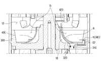
로터리 압축기(1)는 케이스(10), 압축 장치(100), 구동 장치(200), 플랜지 부재(300) 및 머플러 부재(400)를 포함할 수 있다.The rotary compressor 1 may include a
케이스(10)는 로터리 압축기(1)의 외관을 형성할 수 있다. 케이스(10)는 증발기(4)와 연결되어 증발기(4)로부터 냉매를 유입하는 흡입구(11) 및 응축기(2)와 연결되고 로터리 압축기(1)에서 고온, 고압으로 압축된 냉매가 토출되는 토출구(12)를 포함할 수 있다.The
압축 장치(100)는 흡입구로 유입된 냉매가 수용되는 압축 공간을 갖고, 압축 공간에서 냉매를 압축하여 토출구로 배출시킬 수 있다.The
압축 장치(100)는 제1 실린더(110), 제2 실린더(120), 미들 플레이트(130), 제1 토출 플레이트(140), 제2 토출 플레이트(150) 및 추가 플랜지 부재(160)를 포함할 수 있다. 즉, 압축 장치(100)는 트윈 실린더 구조를 가질 수 있다.The
다만, 압축 장치(100)의 구조가 이에 한정되는 것은 아니고, 단일 실린더 구조를 가질 수도 있다. 압축 장치(100)의 상세한 구조는 도 4 내지 도 6을 참조하여 상세히 설명하기로 한다.However, the structure of the
구동 장치(200)는 압축 장치를 구동시킬 수 있다. 구동 장치는 케이스(10)의 내면에 고정된 고정자(210)와, 고정자(210)의 내부에 회전 가능하게 설치되는 회전자(220)와, 회전자(220)의 내부에 회전자(220)와 함께 회전되도록 마련되는 회전축(230)을 포함할 수 있다.The
회전축(230)은 압축 장치(100)와 연결되어 압축 장치(100)의 롤링 피스톤(도 6, 111, 121)을 선회시켜 압축 장치(100)에 유입된 냉매를 압축시킬 수 있다.The
이에 따라, 구동 장치(200)는 회전축(230)을 통해 압축 장치(100)와 연결되어 압축 장치(100)로 동력을 전달할 수 있다.Accordingly, the driving
플랜지 부재(300)는 케이스(10)의 내부를 저압 영역(13) 및 고압 영역(14)으로 구획할 수 있다. 저압 영역(13)은 흡입구(11)와 연통하고 구동 장치(200)가 배치될 수 있다. 고압 영역(14)은 토출구(12)와 연통하고 압축 장치(100)가 배치될 수 있다.The
즉, 케이스(10)의 내부는 플랜지 부재(300)에 의해 저온 저압의 냉매가 배치되는 저압 영역(13)과 고온 고압의 냉매가 배치되는 고압 영역(14)으로 구획될 수 있다.That is, the inside of the
구동 장치(200)는 저압 영역(13)에 배치됨에 따라, 저온 저압의 냉매에 의해 지속적으로 냉각될 수 있으므로 효율이 개선되며 운전 영역이 확대될 수 있다.As the
플랜지 부재(300)는 저압 영역(13)과 압축 장치(100)의 압축 공간을 연통시키는 제1 홀(310)을 포함할 수 있다. 이에 따라, 저압 영역(13)에 위치한 오일 및 냉매를 제1 홀(310)을 따라 고압 영역(14)을 향하여 이동할 수 있다.The
오일은 압축 장치(100)의 회전하는 구성과 회전하지 않는 구성 사이에서 윤활 작용을 할 수 있다.The oil may provide lubrication between the rotating and non-rotating components of the
머플러 부재(400)는 플랜지 부재(300)의 저압 영역(13)을 바라보는 일면(320)을 커버하여 외측에 오일이 저류되는 제1 공간(15)을 형성할 수 있다. 또한, 머플러 부재(400)는 내측에 제1 홀(310)과 연통하는 제2 공간(18)을 형성할 수 있다.The
제1 공간(15)은 머플러 부재(400)의 외면과 플랜지 부재(300)의 측벽 사이에 대략 토러스(torus)의 형상으로 형성될 수 있다. 제2 공간(18)은 머플러 부재(400)의 내면과 플랜지 부재(300)의 일면(320) 사이에 형성될 수 있다.The
머플러 부재(400)는 저압 영역(13)으로부터 제2 공간(18)으로의 냉매 유로를 형성하는 제2 홀(420)을 포함할 수 있다.The
플랜지 부재(300) 및 머플러 부재(400) 중 적어도 하나는 제1 공간(15)으로부터 제1 홀(310)로의 오일 유로를 형성하는 제3 홀(H)을 포함할 수 있다.At least one of the
예를 들어, 도 3을 참조하면, 머플러 부재(400)는 머플러 부재(400)의 외측과 내측이 연통되도록 머플러 부재(400)를 두께 방향으로 관통하는 제3 홀(410)을 포함할 수 있다. 즉, 머플러 부재(400)의 제3 홀(410)은 머플러 부재(400)를 관통하는 오일 유로(O1)를 형성할 수 있다. 이에 따라, 제1 공간(15)에 저류된 오일은 머플러 부재(400)에 형성된 제3 홀(410)을 통하여 제1 홀(310)로 이동할 수 있다.For example, referring to FIG. 3 , the
또한, 도 4를 참조하면, 제3 홀(H)은 플랜지 부재(300)에 형성될 수도 있다. 즉, 플랜지 부재(300)는 제1 공간(15)과 제1 홀(310)을 연통시키는 제3 홀(340)을 포함할 수 있다. 구체적으로, 플랜지 부재(300)는 제1 공간(15)을 둘러싸는 측벽을 포함할 수 있고, 제3 홀(340)은 플랜지 부재(300)의 측벽에 형성되어 제1 홀(310)까지 연장될 수 있다. 이에 따라, 플랜지 부재(300)의 제3 홀(340)은 제1 공간(15)에 저류된 오일이 머플러 부재(400)를 우회하는 오일 유로(O2)를 형성할 수 있다.Also, referring to FIG. 4 , the third hole H may be formed in the
또한, 도 5를 참조하면, 제3 홀(H)은 머플러 부재(400)의 일부가 컷팅되는 개구 영역(440)으로 구현될 수 있다. 구체적으로, 개구 영역(440)은 머플러 부재(400)의 가장자리 중 제1 홀(310)에 대응되는 일 영역에 형성될 수 있다. 즉, 개구 영역(440)은 개구 영역(440)을 통하여 머플러 부재(400)를 관통하는 오일 유로(O3)를 형성할 수 있다.Also, referring to FIG. 5 , the third hole H may be implemented as an
도 3 내지 도 5는 제3 홀(H)이 플랜지 부재(300) 및 머플러 부재(400) 중 어느 하나에만 형성된 것으로 도시하고 있으나, 이에 한정되는 것은 아니고, 제3 홀(H)은 플랜지 부재(300) 및 머플러 부재(400)에 모두 형성될 수도 있다.3 to 5 show that the third hole H is formed in only one of the
즉, 오일은 제1 공간(15) 내 저류되고, 일부가 제3 홀(H)을 통하여 제1 홀(310)로 이동할 수 있다. 또한, 증발기(4)에서 배출되는 냉매 중 액체 상태의 냉매는 제1 공간(15)내에 저장되고, 기체 상태의 냉매만 제2 홀(420)을 통하여 압축 장치(100)로 이동할 수 있다.That is, the oil is stored in the
한편, 오일뿐만 아니라 액체 상태의 냉매도 제3 홀(H)을 통하여 이동할 수 있다. 다만, 오일과 액체 상태의 냉매는 밀도 차이 때문에 층 분리되어 제3 홀(H0)을 통하여 동시에 압축 장치(100)로 이동하지 않으므로, 압축 장치(100) 및 구동 장치(200)의 고장을 방지할 수 있다.Meanwhile, not only oil but also liquid refrigerant may move through the third hole H. However, the refrigerant in the oil and liquid state is separated from the layers due to the difference in density and does not move to the
한편, 흡입구(11)를 통해 케이스(10) 내부로 유입된 기체 상태의 냉매는 제2 홀(420)을 통하여 머플러 부재(400)의 외측으로부터 머플러 부재(400) 내측의 제2 공간(18)으로 이동할 수 있다. 이후, 냉매는 플랜지 부재(300)의 제1 홀(310)을 통하여 압축 장치(100)의 압축 공간으로 이동할 수 있다.On the other hand, the gaseous refrigerant introduced into the
즉, 종래 케이스(10)의 외부에 배치되었던 어큐뮬레이터의 구성이 삭제되고, 케이스(10)의 내부에 배치된 머플러 부재(400)에 의해 형성된 제1 공간(15)이 어큐뮬레이터의 역할을 대신 수행할 수 있다. 이에 따라, 로터리 압축기(1)의 전체 부피는 감소되어 컴팩트한 외관을 가질 수 있다.That is, the structure of the conventional accumulator disposed outside the
머플러 부재(400)는 가장자리로부터 중앙으로 갈수록 플랜지 부재(300)의 일면(320)으로부터 멀어지도록 굴곡지게 형성될 수 있다.The
이에 따라, 머플러 부재(400)의 중앙 부분과 케이스(10)의 내측 사이에 형성되는 제1 공간(15)이 충분한 부피를 가지므로, 제1 공간(15)에는 충분히 많은 양의 오일과 액상 냉매가 저장될 수 있다.Accordingly, since the
제1 공간(15)은 머플러 부재(400)의 중앙 부분과 플랜지 부재(300)의 가장자리를 따라 돌출 형성된 측벽 사이에 형성되는 것으로 도시되어 있으나, 이에 한정되는 것은 아니고, 머플러 부재(400)의 중앙 부분과 케이스(10)의 내측 사이에 형성될 수도 있다.The
머플러 부재(400)의 제2 홀(420)은 머플러 부재(400)의 중앙에 형성되어 회전축(230)이 관통될 수 있다. 또한, 제2 홀(420)의 내경은 회전축(230)의 외경보다 크게 형성되어, 제2 홀(420)과 회전축(230)의 사이의 간격으로 기체 상태의 냉매가 이동할 수 있다. 제2 홀(420)은 제3 홀(H)보다 상측에 형성될 수 있다.The
머플러 부재(400)의 제3 홀(410)은 플랜지 부재(300)의 제1 홀(310)과 마주보도록 형성될 수 있다. 구체적으로, 제1 및 제2 홀(310, 410)은, 고압 영역(14)에서 저압 영역(13)측을 바라보았을 때, 서로 오버랩되도록 배치될 수 있다.The
이에 따라, 제1 공간(15)으로부터 제3 홀(410)을 통과한 오일은 플랜지 부재(300)에 부딪히거나 방해 받지 않으면서 용이하게 고압 영역(14)측으로 이동할 수 있다.Accordingly, the oil passing through the
제3 홀(410)은 머플러 부재(400) 상에 1개로 형성된 것으로 도시되었으나, 개수가 이에 한정되는 것은 아니다. 즉, 제3 홀(410)은 머플러 부재(400)의 둘레 방향을 따라 복수로 형성될 수 있다. 압축 장치(100)의 오일 필요량에 따라, 제3 홀(410)은 머플러 부재(400)의 다양한 높이 및 위치에 형성될 수 있다.Although the
케이스(10)는, 흡입구(11)가 배치되고, 저압 영역(13)을 형성하는 제1 케이스(16) 및 토출구(12)가 배치되고, 고압 영역(14)을 형성하는 제2 케이스(17)를 포함할 수 있다.In the
제1 및 제2 케이스(16, 17)는 용접 등에 의하여 일단이 서로 연결됨에 따라 케이스(10)의 내부 공간을 형성할 수 있다. 한편, 저압 영역(13)에 배치된 구동 장치(200)는 냉매에 의해 지속적으로 냉각되므로 효율이 개선되므로, 구동 장치(200)의 직경이 작아져도 동일한 효율을 가질 수 있다.As ends of the first and
이에 따라, 제2 케이스(17)는 제1 케이스(16)보다 큰 내경을 가질 수 있고, 제2 케이스(17)의 내부에 배치되는 압축 장치(100)의 실린더는 직경 대비 높이가 커져서 배기량이 증대될 수 있다. 즉, 구동 장치(200)의 효율은 나빠지지 않으면서, 동시에 압축 장치(100)의 효율은 증대될 수 있다.Accordingly, the
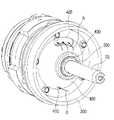
도 6은 본 개시의 일 실시예에 따른 구동 장치의 사시도이다. 도 7은 본 개시의 일 실시예에 따른 압축 장치의 사시도이다. 도 8은 도 7의 압축 장치의 분해 사시도이다.6 is a perspective view of a driving device according to an embodiment of the present disclosure. 7 is a perspective view of a compression device according to an embodiment of the present disclosure. 8 is an exploded perspective view of the compression device of FIG. 7;
도 6 내지 도 8을 참조하면, 압축 장치(100)는 제1 실린더(110), 제2 실린더(120) 및 미들 플레이트(130)를 포함할 수 있다.Referring to FIGS. 6 to 8 , the
제1 실린더(110)는 압축 공간에서 편심을 가지고 선회 운동하는 롤링 피스톤(111) 및 롤링 피스톤(111)과 접하여 압축 공간을 흡입실(V1)과 압축실(V2)로 구획하는 베인(112)을 포함할 수 있다.The
제2 실린더(120)는 압축 공간에서 편심을 가지고 선회 운동하는 롤링 피스톤(121) 및 롤링 피스톤(121)과 접하여 압축 공간을 흡입실(V3)과 압축실(V4)로 구획하는 베인(122)을 포함할 수 있다.The
구체적으로, 롤링 피스톤(111, 121)은 원통 형상으로 형성되며 내부에 회전축(230)과 결합된 편심부(231, 232)가 배치될 수 있다. 회전축(230)이 회전함에 따라 편심부(231, 232)가 이동함으로써, 롤링 피스톤(111, 121)을 선회 이동시킬 수 있다. 제1 및 제2 실린더(110, 120)의 각 롤링 피스톤(111, 121)들은 회전축(230)의 둘레 방향으로 180도의 위상차를 갖도록 편심되어 회전할 수 있다.Specifically, the rolling
미들 플레이트(130)는 제1 및 제2 실린더(110, 120) 사이에 배치되고, 내측에 토출 공간(131)을 가질 수 있다. 토출 공간(131)은 제1 및 제2 실린더(110, 120)로부터 압축된 냉매가 토출되며 토출구(12)와 연통할 수 있다.The
즉, 저압 영역(13)으로부터 머플러 부재(400)의 제2 홀(420) 및 플랜지 부재(300)의 제1 홀(310)을 차례로 통과하여, 압축 장치(100)로 이동한 저온 저압의 냉매는 압축 장치(100)의 압축 공간에서 고온 고압의 냉매로 압축되어, 미들 플레이트(130)의 토출 공간(131)으로 이동할 수 있다. 이후, 고온 고압의 냉매는 토출 공간(131)으로부터 토출구(12)를 통하여 응축기(2)로 이동할 수 있다.That is, the low-temperature, low-pressure refrigerant passed through the
즉, 압축된 냉매의 상술한 이동 경로는 저압 영역(13)과 완전히 분리되므로, 저압 영역(13)과 고압 영역(14) 사이에 차압이 유지될 수 있다.That is, since the above-described moving path of the compressed refrigerant is completely separated from the
미들 플레이트(130)는 제1 실린더(110)의 흡입실(V1)과 제2 실린더(120)의 흡입실(V3)을 연통시키는 제4 홀(132)을 포함할 수 있다.The
즉, 압축되기 전의 저온 저압의 냉매의 일부는 플랜지 부재(300)의 제1 홀(310)을 통하여 제1 실린더(110)의 흡입실(V1)으로 이동하고, 일부는 제4 홀(132)을 통하여 제2 실린더(120)의 흡입실(V3)로 이동할 수 있다. 이에 따라, 냉매는 2개의 제1 및 제2 실린더(110, 120) 각각의 압축 공간에서 효율적으로 압축될 수 있다.That is, part of the low-temperature, low-pressure refrigerant before being compressed moves to the suction chamber V1 of the
압축 장치(100)는 제1 실린더(110)와 미들 플레이트(130)의 사이에 배치되는 제1 토출 플레이트(140) 및 제2 실린더(120)와 미들 플레이트(1300의 사이에 배치되는 제2 토출 플레이트(150)를 포함할 수 있다.The
제1 토출 플레이트(140)는 제1 실린더(110)의 흡입실(V1)과 제4 홀(132)을 연통시키는 제5 홀(141) 및 제1 실린더(110)의 압축실(V2)과 토출 공간(131)을 선택적으로 연통시키는 제1 밸브 장치(142)를 포함할 수 있다.The
제1 밸브 장치(142)는 제1 토출 플레이트(140)의 미들 플레이트(130)를 바라보는 일면에 배치되고, 미들 플레이트(130)의 토출 공간(131)내에서 회전하여 제1 실린더(110)의 압축실(V2)과 토출 공간(131)을 선택적으로 연통시킬 수 있다.The
제2 토출 플레이트(150)는 제2 실린더(120)의 흡입실(V3)과 제4 홀(132)을 연통시키는 제6 홀(151) 및 제2 실린더(120)의 압축실(V4)과 토출 공간(131)을 선택적으로 연통시키는 제2 밸브 장치(152)를 포함할 수 있다.The
제2 밸브 장치(152)는 제1 토출 플레이트(150)의 미들 플레이트(130)를 바라보는 일면에 배치되고, 미들 플레이트(130)의 토출 공간(131)내에서 회전하여 제2 실린더(120)의 압축실(V4)과 토출 공간(131)을 선택적으로 연통시킬 수 있다.The
즉, 제1 및 제2 밸브 장치(142, 152)는 기설정된 압력을 초과하는 경우에만 제1 및 제2 실린더(110, 120)의 압축실(V2, V4)과 미들 플레이트(130)의 토출 공간(131)을 각각 연통시킬 수 있다. 이에 따라, 충분히 고압으로 압축된 냉매만이 미들 플레이트(130)의 토출 공간(131)으로 이동할 수 있다.That is, the first and
또한, 압축되기 전의 저온 저압의 냉매의 일부는 플랜지 부재(300)의 제1 홀(310)을 통하여 제1 실린더(110)의 흡입실(V1)으로 이동하고, 일부는 제5 홀(141), 제4 홀(132) 및 제6 홀(151)을 차례로 통과하여, 제2 실린더(120)의 흡입실(V3)로 이동할 수 있다. 이에 따라, 냉매는 2개의 제1 및 제2 실린더(110, 120) 각각의 압축 공간에서 효율적으로 압축될 수 있다.In addition, part of the low-temperature, low-pressure refrigerant before being compressed moves to the suction chamber V1 of the
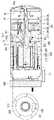
도 9는 본 개시의 일 실시예에 따른 횡형 로터리 압축기의 단면도이다. 도 10은 도 9의 횡형 로터리 압축기의 압축 장치의 사시도이다. 도 11은 도 10의 압축 장치의 분해 사시도이다.9 is a cross-sectional view of a horizontal rotary compressor according to an embodiment of the present disclosure. Fig. 10 is a perspective view of a compression device of the horizontal rotary compressor of Fig. 9; 11 is an exploded perspective view of the compression device of FIG. 10;
도 9 내지 도 11을 참조하면, 구동 장치(100)는 수평하게 배치되고 구동 장치(200)와 연결되는 회전축(230)을 포함할 수 있다. 즉, 도 9 내지 도 11의 로터리 압축기(1)는 횡형(HORIZONTAL TYPE) 로터리 압축기일 수 있다. 도 9 내지 도 11의 로터리 압축기(1)는 상술한 종형 로터리 압축기와 대부분 유사한 구조를 가질 수 있으며, 상술한 구성과 동일한 구성에 대해서는 동일한 부재 번호를 사용하였으며 중복되는 설명은 생략될 수 있다.Referring to FIGS. 9 to 11 , the driving
플랜지 부재(300) 및 머플러 부재(400) 중 적어도 하나는 제1 공간(15)으로부터 제1 홀(310)로의 오일 유로(O)를 형성하는 제3 홀을 포함할 수 있다. 도 9에는 머플러 부재(400)에 제3 홀(410)이 형성되는 것으로 도시되어 있으나, 제3 홀의 위치가 이에 한정되는 것은 아니고, 도 4 또는 도 5에 도시된 것과 같이 다양한 구조로 구현될 수 있다.At least one of the
머플러 부재(400)는 제2 홀(420)보다 하측에 배치되는 중앙홀(430)을 포함할 수 있다. 즉, 회전축(230)은 머플러 부재(400)의 중앙홀(430)을 관통하고, 냉매는 중앙홀(430)보다 상측에 배치되는 제2 홀(420)을 통하여 저압 영역(13)으로부터 고압 영역(14)으로 이동할 수 있다.The
플랜지 부재(300)는 내면이 회전축(230)을 회전 가능하게 지지하고, 외면이 중앙홀(430)에 끼워지는 중앙 영역(330)을 포함할 수 있다. 중앙 영역(330)은 가장자리 영역보다 플랜지 부재(300)의 일면으로부터 멀어지도록 돌출 형성될 수 있다.The
중앙 영역(330)의 외면이 중앙홀(430)에 유격 없이 끼워짐에 따라, 냉매는 플랜지 부재(300)와 머플러 부재(400)의 중앙홀(430) 사이로 이동할 수 없고, 중앙홀(430)보다 상측에 위치한 제2 홀(420)을 통하여 머플러 부재(400)의 내측으로 이동할 수 있다.As the outer surface of the
이에 따라, 제2 홀(420)이 충분히 높게 형성되므로, 제1 공간(15)에 저류된 오일이 의도치 않게 제2 홀(420)이나 중앙홀(430)을 통하여 압축 장치(100)로 이동하는 것이 방지될 수 있다.Accordingly, since the
롤링 피스톤이 편심 회전함에 따라, 실린더의 흡입실의 부피는 반복적으로 증가 및 감소하므로, 보일의 법칙에 따라 흡입실 내부 압력도 반복적으로 증가 및 감소할 수 있다. 즉, 상술한 흡입실의 내부 압력 변화에 따라, 오일은 제3 홀(410) 및 실린더의 흡입실과 연통하는 제1 홀(310)을 통하여, 제1 공간(15)에서 실린더의 흡입실로 이동할 수 있다.As the rolling piston rotates eccentrically, the volume of the suction chamber of the cylinder repeatedly increases and decreases, so the pressure inside the suction chamber can repeatedly increase and decrease according to Boyle's law. That is, according to the aforementioned change in the internal pressure of the suction chamber, oil can move from the
제3 홀(410)은 케이스(10)의 하면과 인접하게 배치될 수 있고, 이에 따라 오일은 제1 공간(15)에 과도하게 축적되지 않고 보다 용이하게 저압 영역(13)으로부터 고압 영역(14)으로 이동할 수 있다.The
로터리 압축기(1)는 일단이 회전축(230)의 내부와 연통되고, 타단이 고압 영역(14)에 저류된 오일에 잠기도록 배치되는 급유관(600)을 더 포함할 수 있다. 급유관(600)은 고압 영역(14) 및 저압 영역(13)의 차압에 의해 고압 영역(14)으로부터 회전축(230)의 내부로 이동하는 오일 유로를 형성할 수 있다.The rotary compressor 1 may further include an
로터리 압축기(1)는 구동 장치(200)에 구동 전류를 공급하는 인버터(500)를 더 포함할 수 있다. 인버터(500)는 제어 장치의 제어 신호에 기초하여 구동 장치(200)에 구동 전류를 공급할 수 있다. 인버터(500)는 직류를 교류로 변환시킴에 따라 구동 장치(200)에 구동 전류를 공급하고, 이에 따라 전력이 개선될 수 있다.The rotary compressor 1 may further include an
한편, 인버터(500)는 지속적인 냉각이 필요한 구성으로, 케이스(10)의 외면 중 저압 영역(13)에 대응하는 곳에 배치될 수 있다. 이에 따라, 별도의 냉각 시스템이나 공간이 없어도, 인버터(500)가 저온의 케이스(10)에 부착됨에 따라 안정적으로 구동될 수 있고, 로터리 압축기(1)는 컴팩트한 외관을 가질 수 있다.Meanwhile, the
이상에서는 본 개시의 바람직한 실시예에 대해서 도시하고, 설명하였으나, 본 개시는 상술한 특정의 실시예에 한정되지 아니하며, 청구범위에서 청구하는 본 개시의 요지를 벗어남이 없이 당해 개시가 속하는 기술분야에서 통상의 지식을 가진자라면 누구든지 다양한 변형 실시가 가능한 것은 물론이고, 그와 같은 변경은 청구범위 기재의 범위 내에 있게 된다.In the above, preferred embodiments of the present disclosure have been shown and described, but the present disclosure is not limited to the specific embodiments described above, and in the technical field to which the disclosure belongs without departing from the gist of the present disclosure claimed in the claims. Anyone skilled in the art can make various modifications, of course, and such changes are within the scope of the claims.
1: 로터리 압축기10: 케이스
100: 압축 장치200: 구동 장치
300: 플랜지 부재400: 머플러 부재
500: 인버터600: 급유관1: rotary compressor 10: case
100: compression device 200: driving device
300: flange member 400: muffler member
500: inverter 600: oil pipe
Claims (15)
Translated fromKorean상기 흡입구로 유입된 냉매가 수용되는 압축 공간을 갖고, 상기 압축 공간에서 냉매를 압축하여 상기 토출구로 배출시키는 압축 장치;
상기 압축 장치를 구동시키는 구동 장치;
상기 케이스의 내부를 상기 흡입구와 연통하고 상기 구동 장치가 배치되는 저압 영역 및 상기 토출구와 연통하고 상기 압축 장치가 배치되는 고압 영역으로 구획하고, 상기 저압 영역과 상기 압축 공간을 연통시키는 제1 홀을 포함하는 플랜지 부재; 및
상기 플랜지 부재의 상기 저압 영역을 바라보는 일면에 배치되어 외측에 오일이 저류되는 제1 공간을 형성하고, 내측에 상기 제1 홀과 연통하는 제2 공간을 형성하고, 상기 저압 영역으로부터 상기 제2 공간으로의 냉매 유로를 형성하는 제2 홀을 포함하는 머플러 부재;를 포함하고,
상기 플랜지 부재 및 상기 머플러 부재 중 적어도 하나는 상기 제1 공간으로부터 상기 제1 홀로의 오일 유로를 형성하는 제3 홀을 포함하는 로터리 압축기.A case including a suction port and a discharge port;
a compression device having a compression space accommodating the refrigerant flowing into the suction port, compressing the refrigerant in the compression space, and discharging the refrigerant through the discharge port;
a driving device that drives the compression device;
A first hole dividing the inside of the case into a low pressure region communicating with the suction port and disposing the drive device and a high pressure region communicating with the discharge port and disposing the compression device, and communicating the low pressure region and the compression space. A flange member comprising; and
It is disposed on one surface of the flange member facing the low pressure region to form a first space in which oil is stored on the outside, and a second space communicating with the first hole is formed on the inside, and the second space is formed from the low pressure region. A muffler member including a second hole forming a refrigerant passage into the space,
At least one of the flange member and the muffler member includes a third hole forming an oil flow path from the first space to the first hole.
상기 머플러 부재는 가장자리로부터 중앙으로 갈수록 상기 플랜지 부재의 상기 일면으로부터 멀어지도록 굴곡지게 형성되는 로터리 압축기.According to claim 1,
The rotary compressor of claim 1 , wherein the muffler member is curved away from the one surface of the flange member toward the center from an edge.
상기 구동 장치는 상기 압축 장치와 연결되는 회전축을 포함하고,
상기 제2 홀은 상기 머플러 부재의 중앙에 형성되어 상기 회전축이 관통되는 로터리 압축기.According to claim 2,
The driving device includes a rotation shaft connected to the compression device,
The second hole is formed at the center of the muffler member so that the rotary shaft passes through the rotary compressor.
상기 제3 홀은 상기 머플러 부재에 상기 제1 홀과 마주보도록 형성되는 로터리 압축기.According to claim 1,
The third hole is formed to face the first hole in the muffler member.
상기 제3 홀은 상기 머플러 부재의 둘레 방향을 따라 복수로 형성되는 로터리 압축기.According to claim 1,
The rotary compressor of claim 1 , wherein a plurality of third holes are formed along a circumferential direction of the muffler member.
상기 압축 장치는,
상기 압축 공간에서 편심을 가지고 선회 운동하는 롤링 피스톤 및 상기 롤링 피스톤과 접하여 상기 압축 공간을 흡입실과 압축실로 구획하는 베인을 각각 포함하는 제1 실린더 및 제2 실린더; 및
상기 제1 및 제2 실린더 사이에 배치되고, 상기 제1 및 제2 실린더로부터 압축된 냉매가 토출되며 상기 토출구와 연통하는 토출 공간을 갖는 미들 플레이트를 포함하는 로터리 압축기.According to claim 1,
The compression device,
a first cylinder and a second cylinder each comprising a rolling piston which rotates with an eccentricity in the compression space and a vane which contacts the rolling piston and divides the compression space into a suction chamber and a compression chamber; and
and a middle plate disposed between the first and second cylinders and having a discharge space communicating with the discharge port through which compressed refrigerant is discharged from the first and second cylinders.
상기 미들 플레이트는 상기 제1 실린더의 흡입실과 상기 제2 실린더의 흡입실을 연통시키는 제4 홀을 포함하는 로터리 압축기.According to claim 6,
The middle plate includes a fourth hole communicating a suction chamber of the first cylinder and a suction chamber of the second cylinder.
상기 압축 장치는,
상기 제1 실린더와 상기 미들 플레이트의 사이에 배치되고, 상기 제1 실린더의 흡입실과 상기 제4 홀을 연통시키는 제5 홀 및 상기 제1 실린더의 압축실과 상기 토출 공간을 선택적으로 연통시키는 제1 밸브 장치를 포함하는 제1 토출 플레이트 및
상기 제2 실린더와 상기 미들 플레이트의 사이에 배치되고, 상기 제2 실린더의 흡입실과 상기 제4 홀을 연통시키는 제6 홀 및 상기 제2 실린더의 압축실과 상기 토출 공간을 선택적으로 연통시키는 제2 밸브 장치를 포함하는 제2 토출 플레이트를 포함하는 로터리 압축기.According to claim 7,
The compression device,
A fifth hole disposed between the first cylinder and the middle plate and communicating the suction chamber of the first cylinder with the fourth hole and a first valve selectively communicating the compression chamber of the first cylinder with the discharge space. A first discharge plate comprising a device and
A sixth hole disposed between the second cylinder and the middle plate and communicating the suction chamber of the second cylinder with the fourth hole and a second valve selectively communicating the discharge space with the compression chamber of the second cylinder. A rotary compressor comprising a second discharge plate comprising a device.
상기 케이스는,
상기 흡입구가 배치되고, 상기 저압 영역을 형성하는 제1 케이스 및
상기 토출구가 배치되고, 상기 고압 영역을 형성하고, 상기 제1 케이스보다 큰 내경을 갖는 제2 케이스를 포함하는 로터리 압축기.According to claim 1,
The case is
a first case in which the inlet is disposed and forms the low pressure region; and
A rotary compressor comprising a second case in which the discharge port is disposed, forming the high-pressure region, and having an inner diameter larger than that of the first case.
상기 구동 장치에 구동 전류를 공급하는 인버터;를 더 포함하고,
상기 인버터는 상기 케이스의 외면 중 상기 저압 영역에 대응하는 곳에 배치되는 로터리 압축기.According to claim 1,
Further comprising an inverter supplying a driving current to the driving device;
The inverter is disposed at a location corresponding to the low pressure region among the outer surfaces of the case.
상기 구동 장치는 수평하게 배치되고 상기 압축 장치와 연결되는 회전축을 포함하고,
상기 머플러 부재는 상기 제2 홀보다 하측에 배치되는 중앙홀을 포함하는 로터리 압축기.According to claim 1,
The driving device includes a rotation shaft disposed horizontally and connected to the compression device,
The rotary compressor of claim 1 , wherein the muffler member includes a central hole disposed below the second hole.
상기 플랜지 부재는 내면이 상기 회전축을 회전 가능하게 지지하고, 외면이 상기 중앙홀에 끼워지는 중앙 영역을 포함하는 로터리 압축기.According to claim 11,
The rotary compressor of claim 1 , wherein an inner surface of the flange member rotatably supports the rotary shaft and an outer surface includes a central region fitted into the central hole.
일단이 상기 회전축의 내부와 연통되고, 타단이 상기 고압 영역에 저류된 오일에 잠기도록 배치되는 급유관;을 더 포함하고,
상기 급유관은 상기 고압 및 저압 영역의 차압에 의해 상기 고압 영역으로부터 상기 회전축의 내부로 이동하는 오일 유로를 형성하는 로터리 압축기.According to claim 11,
An oil supply pipe having one end communicating with the inside of the rotating shaft and the other end being submerged in the oil stored in the high-pressure region; further comprising,
The oil supply pipe forms an oil flow path moving from the high pressure region to the inside of the rotary shaft by a differential pressure between the high pressure region and the low pressure region.
상기 가전 기기는 냉매를 압축하기 위한 로터리 압축기를 포함하고,
상기 로터리 압축기는,
흡입구 및 토출구를 포함하는 케이스;
상기 흡입구로 유입된 냉매가 수용되는 압축 공간을 갖고, 상기 압축 공간에서 냉매를 압축하여 상기 토출구로 배출시키는 압축 장치;
상기 압축 장치를 구동시키는 구동 장치;
상기 케이스의 내부를 상기 흡입구와 연통하고 상기 구동 장치가 배치되는 저압 영역 및 상기 토출구와 연통하고 상기 압축 장치가 배치되는 고압 영역으로 구획하고, 상기 저압 영역과 상기 압축 공간을 연통시키는 제1 홀을 포함하는 플랜지 부재; 및
상기 플랜지 부재의 상기 저압 영역을 바라보는 일면에 배치되어 외측에 오일이 저류되는 제1 공간을 형성하고, 내측에 상기 제1 홀과 연통하는 제2 공간을 형성하고, 상기 저압 영역으로부터 상기 제2 공간으로의 냉매 유로를 형성하는 제2 홀을 포함하는 머플러 부재;를 포함하고,
상기 플랜지 부재 및 상기 머플러 부재 중 적어도 하나는 상기 제1 공간으로부터 상기 제1 홀로의 오일 유로를 형성하는 제3 홀을 포함하는 가전기기.It relates to a home appliance that regulates temperature through heat exchange with the outside using a refrigerant.
The home appliance includes a rotary compressor for compressing the refrigerant,
The rotary compressor,
A case including a suction port and a discharge port;
a compression device having a compression space accommodating the refrigerant flowing into the suction port, compressing the refrigerant in the compression space, and discharging the refrigerant through the discharge port;
a driving device that drives the compression device;
A first hole dividing the inside of the case into a low pressure region communicating with the suction port and disposing the drive device and a high pressure region communicating with the discharge port and disposing the compression device, and communicating the low pressure region and the compression space. A flange member comprising; and
It is disposed on one surface of the flange member facing the low pressure region to form a first space in which oil is stored on the outside, and a second space communicating with the first hole is formed on the inside, and the second space is formed on the inside from the low pressure region. A muffler member including a second hole forming a refrigerant passage into the space,
At least one of the flange member and the muffler member includes a third hole forming an oil flow path from the first space to the first hole.
상기 가전기기는 에어컨, 냉장고 및 냉동고 중 하나인 가전기기.According to claim 14,
The home appliance is one of an air conditioner, a refrigerator and a freezer.
Priority Applications (3)
| Application Number | Priority Date | Filing Date | Title |
|---|---|---|---|
| KR1020210092817AKR20230013200A (en) | 2021-07-15 | 2021-07-15 | Rotary compressor and home appliance including the same |
| PCT/KR2021/018106WO2023286942A1 (en) | 2021-07-15 | 2021-12-02 | Rotary compressor and home appliance comprising same |
| US17/743,868US12044224B2 (en) | 2021-07-15 | 2022-05-13 | Rotary compressor and home appliance including the same |
Applications Claiming Priority (1)
| Application Number | Priority Date | Filing Date | Title |
|---|---|---|---|
| KR1020210092817AKR20230013200A (en) | 2021-07-15 | 2021-07-15 | Rotary compressor and home appliance including the same |
Publications (1)
| Publication Number | Publication Date |
|---|---|
| KR20230013200Atrue KR20230013200A (en) | 2023-01-26 |
Family
ID=84919418
Family Applications (1)
| Application Number | Title | Priority Date | Filing Date |
|---|---|---|---|
| KR1020210092817APendingKR20230013200A (en) | 2021-07-15 | 2021-07-15 | Rotary compressor and home appliance including the same |
Country Status (2)
| Country | Link |
|---|---|
| KR (1) | KR20230013200A (en) |
| WO (1) | WO2023286942A1 (en) |
Family Cites Families (5)
| Publication number | Priority date | Publication date | Assignee | Title |
|---|---|---|---|---|
| KR890016436U (en)* | 1988-01-30 | 1989-08-19 | ||
| KR20010076889A (en)* | 2000-01-28 | 2001-08-17 | 구자홍 | Low pressure type rotary compressor |
| WO2006071929A2 (en)* | 2004-12-29 | 2006-07-06 | Aspen Compressor, Llc. | Miniature rotary compressor, and methods related thereto |
| JP2009167829A (en)* | 2008-01-11 | 2009-07-30 | Fujitsu General Ltd | Rotary compressor |
| KR102243832B1 (en)* | 2014-01-23 | 2021-04-23 | 삼성전자주식회사 | Closed type rotary compressor |
- 2021
- 2021-07-15KRKR1020210092817Apatent/KR20230013200A/enactivePending
- 2021-12-02WOPCT/KR2021/018106patent/WO2023286942A1/ennot_activeCeased
Also Published As
| Publication number | Publication date |
|---|---|
| WO2023286942A1 (en) | 2023-01-19 |
Similar Documents
| Publication | Publication Date | Title |
|---|---|---|
| US10378539B2 (en) | System including high-side and low-side compressors | |
| CN108397387B (en) | Co-rotating compressor with multiple compression mechanisms and system with same | |
| CN100585186C (en) | variable capacity rotary compressor | |
| KR101316247B1 (en) | 2 stage rotary compressor | |
| US8419395B2 (en) | Compressor and refrigeration apparatus | |
| WO2013005568A1 (en) | Multi-cylinder rotary compressor and refrigeration cycle device | |
| US12044224B2 (en) | Rotary compressor and home appliance including the same | |
| JP4591350B2 (en) | Refrigeration equipment | |
| US20060090488A1 (en) | Apparatus for changing capacity of multi-stage rotary compressor | |
| US20100054978A1 (en) | Injectible two-stage compression rotary compressor | |
| US20090007590A1 (en) | Refrigeration System | |
| KR102750451B1 (en) | Rotary compressor and home appliance including the same | |
| KR101587174B1 (en) | Rotary compressor | |
| JP6791234B2 (en) | Multi-stage compression system | |
| US12055325B2 (en) | Rotary compressor and home appliance including the same | |
| CN100400883C (en) | Device for varying the capacity of a multi-stage rotary compressor | |
| US11953001B2 (en) | Horizontal type rotary compressor and home appliance including the same | |
| JPH11241693A (en) | Compressor | |
| KR20230013200A (en) | Rotary compressor and home appliance including the same | |
| KR20230013201A (en) | Horizontal type rotary compressor and home appliance including the same | |
| US20250027496A1 (en) | Rotary compressor and home appliance including same | |
| US20250012278A1 (en) | Screw compressor and freezer | |
| KR20230173540A (en) | Rotary compressor and home appliance including the same | |
| KR20240003656A (en) | Rotary compressor and home appliance including the same | |
| KR20230121233A (en) | Rotary compressor and home appliance including the same |
Legal Events
| Date | Code | Title | Description |
|---|---|---|---|
| PA0109 | Patent application | Patent event code:PA01091R01D Comment text:Patent Application Patent event date:20210715 | |
| PG1501 | Laying open of application | ||
| A201 | Request for examination | ||
| PA0201 | Request for examination | Patent event code:PA02012R01D Patent event date:20240617 Comment text:Request for Examination of Application Patent event code:PA02011R01I Patent event date:20210715 Comment text:Patent Application |