KR20230013170A - Method and apparatus for reliably transferring signals between electronic components - Google Patents
Method and apparatus for reliably transferring signals between electronic componentsDownload PDFInfo
- Publication number
- KR20230013170A KR20230013170AKR1020237001779AKR20237001779AKR20230013170AKR 20230013170 AKR20230013170 AKR 20230013170AKR 1020237001779 AKR1020237001779 AKR 1020237001779AKR 20237001779 AKR20237001779 AKR 20237001779AKR 20230013170 AKR20230013170 AKR 20230013170A
- Authority
- KR
- South Korea
- Prior art keywords
- connector
- electronic
- watch
- electrically conductive
- contact
- Prior art date
- Legal status (The legal status is an assumption and is not a legal conclusion. Google has not performed a legal analysis and makes no representation as to the accuracy of the status listed.)
- Granted
Links
Images


Classifications
- G—PHYSICS
- G04—HOROLOGY
- G04G—ELECTRONIC TIME-PIECES
- G04G17/00—Structural details; Housings
- G04G17/02—Component assemblies
- G04G17/06—Electric connectors, e.g. conductive elastomers
- G—PHYSICS
- G04—HOROLOGY
- G04G—ELECTRONIC TIME-PIECES
- G04G17/00—Structural details; Housings
- G04G17/08—Housings
- G—PHYSICS
- G04—HOROLOGY
- G04G—ELECTRONIC TIME-PIECES
- G04G21/00—Input or output devices integrated in time-pieces
- G—PHYSICS
- G06—COMPUTING OR CALCULATING; COUNTING
- G06F—ELECTRIC DIGITAL DATA PROCESSING
- G06F1/00—Details not covered by groups G06F3/00 - G06F13/00 and G06F21/00
- G06F1/16—Constructional details or arrangements
- G06F1/1613—Constructional details or arrangements for portable computers
- G06F1/1633—Constructional details or arrangements of portable computers not specific to the type of enclosures covered by groups G06F1/1615 - G06F1/1626
- G06F1/1675—Miscellaneous details related to the relative movement between the different enclosures or enclosure parts
- G06F1/1681—Details related solely to hinges
- H—ELECTRICITY
- H01—ELECTRIC ELEMENTS
- H01R—ELECTRICALLY-CONDUCTIVE CONNECTIONS; STRUCTURAL ASSOCIATIONS OF A PLURALITY OF MUTUALLY-INSULATED ELECTRICAL CONNECTING ELEMENTS; COUPLING DEVICES; CURRENT COLLECTORS
- H01R35/00—Flexible or turnable line connectors, i.e. the rotation angle being limited
- H01R35/04—Turnable line connectors with limited rotation angle with frictional contact members
- H—ELECTRICITY
- H01—ELECTRIC ELEMENTS
- H01R—ELECTRICALLY-CONDUCTIVE CONNECTIONS; STRUCTURAL ASSOCIATIONS OF A PLURALITY OF MUTUALLY-INSULATED ELECTRICAL CONNECTING ELEMENTS; COUPLING DEVICES; CURRENT COLLECTORS
- H01R39/00—Rotary current collectors, distributors or interrupters
- H01R39/64—Devices for uninterrupted current collection
- H—ELECTRICITY
- H01—ELECTRIC ELEMENTS
- H01R—ELECTRICALLY-CONDUCTIVE CONNECTIONS; STRUCTURAL ASSOCIATIONS OF A PLURALITY OF MUTUALLY-INSULATED ELECTRICAL CONNECTING ELEMENTS; COUPLING DEVICES; CURRENT COLLECTORS
- H01R2201/00—Connectors or connections adapted for particular applications
- H01R2201/16—Connectors or connections adapted for particular applications for telephony
Landscapes
- Engineering & Computer Science (AREA)
- Physics & Mathematics (AREA)
- General Physics & Mathematics (AREA)
- Computer Hardware Design (AREA)
- Theoretical Computer Science (AREA)
- Human Computer Interaction (AREA)
- General Engineering & Computer Science (AREA)
- Electric Clocks (AREA)
- Coupling Device And Connection With Printed Circuit (AREA)
- Electromechanical Clocks (AREA)
- Details Of Connecting Devices For Male And Female Coupling (AREA)
Abstract
Translated fromKoreanDescription
Translated fromKorean관련 출원에 대한 상호 참조CROSS REFERENCES TO RELATED APPLICATIONS
본 출원은 2018년 9월 25일에 출원된 미국 특허 출원 16/140,679호의 연속이며, 개시 내용은 참조로서 본 출원에 모두 포함된다.This application is a continuation of US patent application Ser. No. 16/140,679, filed on September 25, 2018, the disclosure of which is incorporated herein by reference in its entirety.
기존의 전자 시계 및 활동 모듈은 시계 밴드로 또는 시계 밴드로부터 신호를 전송하지 않는다. 그러나, 전자 시계 산업은 고급 바이오 센싱으로 이동하고 있어서, 시계 밴드에 추가 센서, 배터리 및/또는 카메라를 배치해야 할 수 있으며, 이를 위해서는 시계 밴드와 전자 시계 또는 활동 모듈 간의 전자 연결이 필요하다.Existing electronic watches and activity modules do not transmit signals to or from the watch band. However, as the electronic watch industry is moving towards advanced bio-sensing, it may be necessary to place additional sensors, batteries and/or cameras in the watch band, which requires an electronic connection between the watch band and the electronic watch or activity module.
US 2004/074045 A1, EP 2 813 907 A2, CN 108 021 020 A, CN 108 594 629 AUS 2004/074045 A1, EP 2 813 907 A2, CN 108 021 020 A, CN 108 594 629 A
본 발명은 추가 에너지를 사용하지 않고 제1 부품과 제2 부품 사이의 회전 결합을 통해 제1 부품(예컨대, 시계 밴드)과 제2 부품(예컨대, 전자 시계) 간에 신호를 안정적으로 전송할 수 있는 전자 시계 시스템 및 전자 힌지 시스템을 제공한다.The present invention is an electronic device capable of stably transmitting a signal between a first part (eg, a watch band) and a second part (eg, an electronic watch) through a rotational coupling between the first part and the second part without using additional energy. A clock system and an electronic hinge system are provided.
본 발명의 일 양태는 제1 부품 및 제2 부품을 포함하는 전자 힌지 시스템을 제공한다. 제1 부품은 제1 인클로저, 제1 인클로저 내에서 연장되는 제1 기판, 제1 인클로저의 단부에 배치된 제1 커넥터 및 제1 커넥터 내에 배치된 복수의 만곡된 부재를 포함할 수 있다. 제1 기판은 전기 전도성 부재 및 전기 전도성 부재와 전기적으로 연결된 하나 이상의 마이크로 전자 장치를 가질 수 있다. 제1 커넥터는 제1 커넥터를 통해 제1 방향으로 연장되는 길이방향 개구를 가질 수 있다. 제1 커넥터는 제1 방향을 가로지르는 제2 방향에서 제1 커넥터 내로 연장되고, 제1 방향으로 서로 이격된 복수의 제1 개구를 가질 수 있다. 만곡된 부재들은 전기 전도성일 수 있고, 제1 방향으로 서로 이격될 수 있다. 각각의 만곡된 부재는 길이방향 개구 주위에서 적어도 부분적으로 연장되는 내부 표면 및 내부 표면의 반대편에 있는 외부 표면을 가질 수 있다. 각각의 만곡된 부재의 외부 표면의 만곡된 부분은 복수의 제1 개구 중 하나에서 각각 노출될 수 있다. 각각의 만곡된 부재는 제1 부품의 전기 전도성 부재 중 적어도 하나와 각각 전기적으로 연결될 수 있다. 제2 부품은 제2 인클로저 및 제2 인클로저의 단부에 배치된 제2 커넥터를 포함할 수 있다. 제1 커넥터는 제2 커넥터와 정합하도록 구성될 수 있어서, 제1 부품이 제2 부품과 결합될 때, 제1 커넥터는 제2 커넥터와 회전 가능하게 결합된다.One aspect of the present invention provides an electronic hinge system comprising a first component and a second component. The first component may include a first enclosure, a first substrate extending within the first enclosure, a first connector disposed at an end of the first enclosure, and a plurality of curved members disposed within the first connector. The first substrate can have an electrically conductive member and one or more microelectronic devices electrically connected to the electrically conductive member. The first connector may have a longitudinal opening extending in a first direction through the first connector. The first connector may have a plurality of first openings extending into the first connector in a second direction transverse to the first direction and spaced apart from each other in the first direction. The curved members may be electrically conductive and may be spaced apart from each other in the first direction. Each curved member can have an inner surface extending at least partially around the longitudinal opening and an outer surface opposite the inner surface. A curved portion of the outer surface of each curved member may be respectively exposed at one of the plurality of first openings. Each curved member may be electrically connected to at least one of the electrically conductive members of the first part, respectively. The second component may include a second enclosure and a second connector disposed at an end of the second enclosure. The first connector can be configured to mate with the second connector, such that when the first component is engaged with the second component, the first connector is rotatably engaged with the second connector.
본 발명의 다른 양태는 전자 시계 밴드, 전자 시계 밴드와 회전 가능하게 결합된 리셉터클 및 전자 시계를 포함하는 전자 시계 시스템을 제공한다. 전자 시계 밴드는 제1 인클로저 내에서 연장되는 제1 가요성 기판을 갖는 제1 가요성 인클로저 및 제1 인클로저의 단부에 배치되고 제1 커넥터 내에 배치된 복수의 만곡된 부재를 갖는 제1 커넥터를 포함할 수 있다. 제1 기판은 전기 전도성 부재 및 전기 전도성 부재와 전기적으로 연결된 하나 이상의 마이크로 전자 장치를 가질 수 있다. 만곡된 부재들은 전기 전도성일 수 있고, 서로 이격될 수 있다. 각각의 만곡된 부재는 제1 기판의 전기 전도성 부재 중 적어도 하나와 각각 전기적으로 연결될 수 있다. 리셉터클은 원형 레지(ledge) 및 원형 레지 내에 배치되고 내부에 배치된 복수의 접점을 갖는 중간 커넥터를 포함할 수 있다. 접점은 전기 전도성일 수 있고, 원주 방향으로 서로 이격될 수 있다. 각각의 접점은 원형 레지의 하부 표면에 노출된 제1 단부 및 하부 표면에 대향하는 원형 레지의 상부 표면에 노출된 제2 단부를 가질 수 있다. 접점의 제1 단부는 복수의 만곡된 부재와 결합되고, 전기적으로 연결될 수 있다.Another aspect of the present invention provides an electronic watch system including an electronic watch band, a receptacle rotatably coupled with the electronic watch band, and an electronic watch. The electronic watch band includes a first flexible enclosure having a first flexible board extending within the first enclosure and a first connector disposed at an end of the first enclosure and having a plurality of curved members disposed within the first connector. can do. The first substrate can have an electrically conductive member and one or more microelectronic devices electrically connected to the electrically conductive member. The curved members may be electrically conductive and may be spaced apart from each other. Each curved member may be electrically connected to at least one of the electrically conductive members of the first substrate, respectively. The receptacle may include a circular ledge and an intermediate connector disposed within the circular ledge and having a plurality of contacts disposed therein. The contacts may be electrically conductive and spaced from each other in a circumferential direction. Each contact may have a first end exposed on the lower surface of the circular ledge and a second end exposed on the upper surface of the circular ledge opposite the lower surface. A first end of the contact may be coupled to and electrically connected to the plurality of curved members.
전자 시계는 제2 인클로저 내에서 연장되는 제2 기판을 갖는 제2 인클로저 및 제2 인클로저의 표면에 배치되고 제2 커넥터 내에 배치된 복수의 핀을 갖는 제2 커넥터를 포함할 수 있다. 제2 기판은 전기 전도성 부재 및 전기 전도성 부재와 전기적으로 연결된 하나 이상의 마이크로 전자 장치를 가질 수 있다. 핀은 전기 전도성일 수 있고, 원주 방향으로 서로 이격될 수 있다. 각각의 핀은 제2 인클로저의 하부 표면에 노출된 자유 단부를 가질 수 있다. 각각의 핀은 제2 부품의 전기 전도성 부재 중 적어도 하나와 각각 전기적으로 연결될 수 있다. 복수의 핀은 복수의 접점과 정합하도록 구성될 수 있어서, 전자 시계가 리셉터클과 결합될 때, 핀의 자유 단부가 접점의 제2 단부와 결합되고 제2 단부와 전기적으로 연결된다.The electronic watch may include a second enclosure having a second substrate extending within the second enclosure and a second connector disposed on a surface of the second enclosure and having a plurality of pins disposed in the second connector. The second substrate may have an electrically conductive member and one or more microelectronic devices electrically connected to the electrically conductive member. The pins may be electrically conductive and spaced from each other in a circumferential direction. Each pin may have a free end exposed to the lower surface of the second enclosure. Each pin may be electrically connected to at least one of the electrically conductive members of the second component, respectively. The plurality of pins may be configured to mate with the plurality of contacts such that when the electronic watch is coupled with the receptacle, free ends of the pins engage and electrically connect with second ends of the contacts.
본 발명의 또 다른 양태는 가요성 인클로저, 가요성 인클로저 내에서 연장되는 가요성 기판, 가요성 인클로저의 단부에 배치된 커넥터 및 커넥터 내에 배치된 복수의 만곡된 부재를 포함하는 전자 시계 밴드를 제공한다. 가요성 기판은 전기 전도성 부재 및 전기 전도성 부재와 전기적으로 연결된 하나 이상의 마이크로 전자 장치를 가질 수 있다. 커넥터는 커넥터를 통해 제1 방향으로 연장되는 길이방향 개구를 가질 수 있다. 커넥터는 제1 방향을 가로지르는 제2 방향에서 커넥터 내로 연장되고, 제1 방향으로 서로 이격된 복수의 횡방향 개구를 가질 수 있다. 만곡된 부재들은 전기 전도성일 수 있고, 제1 방향으로 서로 이격될 수 있다. 각각의 만곡된 부재는 길이방향 개구 주위에서 적어도 부분적으로 연장되는 내부 표면 및 내부 표면의 반대편에 있는 외부 표면을 가질 수 있다. 각각의 만곡된 부재의 외부 표면의 만곡된 부분은 복수의 개구 중 하나에서 각각 노출될 수 있다. 각각의 만곡된 부재는 전기 전도성 부재 중 적어도 하나와 각각 전기적으로 연결될 수 있다.Another aspect of the present invention provides an electronic watch band comprising a flexible enclosure, a flexible substrate extending within the flexible enclosure, a connector disposed at an end of the flexible enclosure, and a plurality of curved members disposed within the connector. . The flexible substrate can have an electrically conductive member and one or more microelectronic devices electrically connected to the electrically conductive member. The connector may have a longitudinal opening extending through the connector in a first direction. The connector may have a plurality of transverse openings extending into the connector in a second direction transverse to the first direction and spaced apart from each other in the first direction. The curved members may be electrically conductive and may be spaced apart from each other in the first direction. Each curved member can have an inner surface extending at least partially around the longitudinal opening and an outer surface opposite the inner surface. A curved portion of the outer surface of each curved member may be respectively exposed at one of the plurality of openings. Each curved member may be electrically connected to at least one of the electrically conductive members, respectively.
도 1a는 본 발명의 양태에 따른 전자 시계 시스템의 사시도이다.
도 1b는 도 1a의 시계 밴드의 다른 사시도이다.
도 1c는 도 1a의 시계 밴드의 커넥터의 부분적으로 투명한 확대 사시도이다.
도 1d는 도 1a의 전자 시계의 커넥터의 사시도이다.
도 1e는 도 1a의 시계 밴드와 전자 시계 사이의 커플링의 부분적으로 투명한 확대 사시도이다.
도 1f는 제1 위치에서 도시된 도 1a의 시계 밴드와 전자 시계 사이의 커플링의 측 단면도이다.
도 1g는 제2 위치에서 도시된 도 1a의 시계 밴드와 전자 시계 사이의 커플링의 다른 측 단면도이다.
도 2a는 본 발명의 양태에 따른 도 1f의 링의 변형의 측 단면도이다.
도 2b는 본 발명의 양태에 다른 도 1f의 커넥터의 변형의 측 단면도이다.
도 2c 내지 도 2e는 본 발명의 양태에 따른 도 1f의 접점의 변형의 측 단면도이다.
도 2f는 도 1f, 도 2d 및 도 2e에 도시된 접점의 부분적으로 투명한 확대 사시도이다.
도 3a는 본 발명의 양태에 따른 도 1b의 시계 밴드의 커넥터의 변형의 확대 사시도이다.
도 3b는 본 발명의 양태에 따른 도 1d의 전자 시계의 커넥터의 변형의 확대 사시도이다.
도 3c는 도 3a의 시계 밴드의 커넥터 및 도 3b의 전자 시계의 커넥터의 확대 사시도이다.
도 3d는 도 3a의 시계 밴드와 도 3b의 전자 시계 간의 커플링의 측 단면도이다.
도 4a는 본 발명의 양태에 따른 전자 시계 시스템의 사시도이다.
도 4b는 도 4a의 시계 밴드, 리셉터클 및 전자 시계 간의 커플링의 부분적으로 투명한 확대 사시도이다.
도 4c는 전자 시계가 리셉터클로부터 이격된 상태에서 도 4a의 시계 밴드, 리셉터클 및 전자 시계의 부분적으로 투명한 확대 사시도이다.
도 4d 및 4e는 도 4a의 리셉터클의 커넥터의 확대 사시도이다.
도 4f는 도 4a의 전자 시계의 커넥터의 확대 사시도이다.
도 4g는 도 4a의 시계 밴드, 리셉터클 및 전자 시계 간의 커플링의 측 단면도이다.
도 4h는 한 쌍의 접점만이 서로 회전적으로 정렬된 상태로 도시된 도 4a의 리셉터클과의 접점과 전자 시계 간의 커플링의 개략도이다.
도 5는 본 발명의 양태에 따른 활동 모듈 시스템의 사시도이다.
도 6은 본 발명의 양태에 따른 아날로그 시계 시스템의 사시도이다.
도 7은 본 발명의 양태에 따른 랩탑 힌지 시스템의 사시도이다.1A is a perspective view of an electronic watch system in accordance with an aspect of the present invention.
FIG. 1B is another perspective view of the watch band of FIG. 1A.
FIG. 1C is an enlarged, partially transparent perspective view of the connector of the watch band of FIG. 1A.
Fig. 1d is a perspective view of a connector of the electronic watch of Fig. 1a.
FIG. 1E is an enlarged, partially transparent perspective view of the coupling between the watch band of FIG. 1A and the electronic watch.
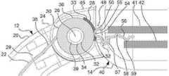
FIG. 1F is a cross-sectional side view of the coupling between the electronic watch and the watch band of FIG. 1A shown in a first position.
FIG. 1G is another cross-sectional side view of the coupling between the watch band and the electronic watch of FIG. 1A shown in a second position.
2A is a cross-sectional side view of a variant of the ring of FIG. 1F in accordance with an aspect of the present invention.
2B is a cross-sectional side view of a variant of the connector of FIG. 1F in accordance with an aspect of the present invention.
2C-2E are cross-sectional side views of variations of the contact of FIG. 1F in accordance with aspects of the present invention.
Fig. 2f is an enlarged, partially transparent perspective view of the contact shown in Figs. 1f, 2d and 2e;
3A is an enlarged perspective view of a variant of a connector of the watch band of FIG. 1B in accordance with an aspect of the present invention.
3B is an enlarged perspective view of a variant of a connector of the electronic watch of FIG. 1D in accordance with an aspect of the present invention.
3C is an enlarged perspective view of a connector of the watch band of FIG. 3A and a connector of the electronic watch of FIG. 3B.
3D is a cross-sectional side view of the coupling between the watch band of FIG. 3A and the electronic watch of FIG. 3B.
4A is a perspective view of an electronic watch system in accordance with an aspect of the present invention.
FIG. 4B is an enlarged, partially transparent perspective view of the coupling between the watch band, receptacle and electronic watch of FIG. 4A.
FIG. 4C is an enlarged, partially transparent perspective view of the watch band, receptacle and electronic watch of FIG. 4A with the electronic watch spaced apart from the receptacle.
4d and 4e are enlarged perspective views of the connector of the receptacle of FIG. 4a.
Fig. 4f is an enlarged perspective view of a connector of the electronic watch of Fig. 4a;
Figure 4g is a cross-sectional side view of the coupling between the watch band, receptacle and electronic watch of Figure 4a.
FIG. 4H is a schematic diagram of coupling between an electronic watch and contacts with the receptacle of FIG. 4A with only one pair of contacts shown rotationally aligned with each other.
5 is a perspective view of an activity module system in accordance with an aspect of the present invention.
6 is a perspective view of an analog clock system in accordance with an aspect of the present invention.
7 is a perspective view of a laptop hinge system in accordance with an aspect of the present invention.
개요outline
기술은 일반적으로 시계와 밴드 사이, 키보드와 스크린 사이 또는 다른 장치의 이동 가능한 부품 사이에서 신호를 안정적으로 전송하도록 구성된 전자 힌지 시스템 또는 메커니즘과 관련된다. 특히, 메커니즘은 제1 부품과 제2 부품 사이에 회전 가능한 전기 연결을 제공한다. 메커니즘은 제2 부품 내의 복수의 전기 전도성 접점과 정합하는 제1 부품 내의 복수의 만곡된 부재(예를 들어, 만곡된 부재는 링이거나 또는 만곡된 부재는 만곡된 부분 및 임의의 형상을 가질 수 있는 부분을 갖는 부재임)를 포함한다. 만곡된 부재(예컨대, 링)가 접점에 대해 회전할 때 접점의 단부가 만곡된 부재(예컨대, 링)의 각각의 원주 표면을 따라 슬라이딩할 수 있기 때문에 만곡된 부재(예컨대, 링)와 접점 사이의 전기적 연결은 회전 중에 유지될 수 있다.The technology generally involves an electronic hinge system or mechanism configured to reliably transmit signals between a watch and a band, between a keyboard and a screen, or between movable parts of other devices. In particular, the mechanism provides a rotatable electrical connection between the first part and the second part. The mechanism may include a plurality of curved members in the first part that mate with a plurality of electrically conductive contacts in the second part (eg, the curved member may be a ring or the curved member may have a curved portion and any shape). It is a member having a part). Between the curved member (eg ring) and the contact point as the ends of the contact point can slide along the respective circumferential surface of the curved member (eg ring) as the curved member (eg ring) rotates relative to the contact point. The electrical connection of can be maintained during rotation.
일부 구현 예들에서, 제1 부품은 시계 밴드일 수 있고, 제2 부품은 스마트 시계와 같은 전자 시계일 수 있다. 제1 부품은 복수의 만곡된 부재를 갖는 커넥터를 포함할 수 있다. 일부 구현 예들에서, 복수의 만곡된 부재는 서로 이격된 전기 전도성 링의 열을 포함한다. 링은 제1 부품(예컨대, 시계 밴드)을 제2 부품(예컨대, 스마트 시계)의 커넥터에 결합하는데 사용될 수 있는 기존 핀을 수용하도록 구성된 제1 부품의 단일 개구(또는 길이방향 개구) 주위로 연장된다. 제2 부품은 서로 이격된 전기 전도성 접점의 열을 갖는 커넥터를 포함할 수 있다. 접점은 시계 밴드가 스마트 시계에 결합될 때 링과 정합하도록 구성된다. 사용자가 일반적으로 이동하는 동안 시계 밴드가 스마트 시계에 대해 회전함에 따라 접점과 링 사이의 전기 연결이 유지된다.In some implementations, the first component can be a watch band and the second component can be an electronic watch, such as a smart watch. The first component may include a connector having a plurality of curved members. In some implementations, the plurality of curved members include rows of electrically conductive rings spaced apart from each other. The ring extends around a single opening (or longitudinal opening) of the first part configured to receive an existing pin that can be used to couple a first part (eg watch band) to a connector of a second part (eg smart watch). do. The second component may include a connector having rows of electrically conductive contacts spaced apart from each other. The contacts are configured to mate with the ring when the watch band is coupled to the smart watch. The electrical connection between the contacts and the ring is maintained as the watch band rotates relative to the smart watch while the user is generally mobile.
위에서 설명한 시계 밴드 및 스마트 시계 구현 예에서, 전기 전도성 접점의 열은 링의 열과 하나 또는 두 개의 기판 또는 인쇄 회로 기판(PCB) 사이의 다양한 유형의 연결을 포함할 수 있다. 예를 들어, 접점은 접점의 단부를 단축하거나 또는 접점의 단부가 제2 PCB와 접촉하는 위치에 전도성 패드를 제공하지 않음으로써 링 중 하나와 제1 PCB 사이에서만 연장될 수 있다. 다른 예에서, 접점은 제1 PCB와 제2 PCB 사이에서 연장될 수 있지만, 임의의 링으로 연장되지 않도록 단축될 수 있다. 특정 구현 예에서, 동일한 접점의 열이 사용될 수 있거나 또는 전술한 접점 변형 중 하나 이상이 단일 스마트 시계 커넥터에 결합될 수 있다. 이와 관련하여, PCB들은 주어진 통신에 대해 하나 이상의 접점을 프로그래밍 방식으로 선택할 수 있다.In the watch band and smart watch implementation examples described above, the rows of electrically conductive contacts may include various types of connections between the rows of rings and one or two substrates or printed circuit boards (PCBs). For example, the contacts may extend only between one of the rings and the first PCB by shortening the ends of the contacts or by not providing conductive pads where the ends of the contacts contact the second PCB. In another example, the contact may extend between the first PCB and the second PCB, but may be shortened such that it does not extend into any ring. In certain implementations, the same row of contacts may be used, or one or more of the foregoing contact variants may be combined into a single smart watch connector. In this regard, PCBs can programmatically select one or more contacts for a given communication.
시계 밴드는 다양한 유형의 시계에 결합될 수 있다. 일 예에서, 시계 밴드는 스마트 시계 특징을 가능하게 하면서 종래의 아날로그 시계에 결합될 수 있다. 예를 들어, 시계 밴드는 아날로그 시계와 전기적으로 연결되지 않을 수 있지만, 시계 밴드는 스마트 특징을 위한 디스플레이 및 인터페이스로서 역할을 하는 스마트 폰과 통신할 수 있다. 다른 예에서, 시계 밴드는 스마트 시계에 결합될 수 있으며, 이는 보조 전원, 카메라 또는 활동 특정 기능과 같이, 다양한 부품 및/또는 기능이 시계 밴드와 시계 사이에 분배되도록 한다. 시계 밴드는 또한 디스플레이 스크린이 없는 스마트 모듈에 결합될 수도 있다. 이러한 구현 예에서, 시계 밴드는 스마트 모듈과 기능을 분리 및/또는 공유할 수 있지만, 디스플레이 및 인터페이스로 스마트 폰이 사용될 수 있다. 일 구현 예에서, 전술한 링-접점 회전 커플링은 랩탑 키보드로부터 랩탑 스크린으로 신호가 전송될 수 있도록 하나 이상의 힌지에 통합될 수 있다.Watch bands can be incorporated into many types of watches. In one example, the watch band can be coupled to a conventional analog watch while enabling smart watch features. For example, a watch band may not be electrically connected to an analog watch, but the watch band may communicate with a smart phone that serves as a display and interface for smart features. In another example, a watch band may be coupled to a smart watch, which allows various components and/or functions to be distributed between the watch band and the watch, such as auxiliary power, camera, or activity specific functions. The watch band can also be incorporated into a smart module without a display screen. In this implementation, the watch band may separate and/or share functionality with the smart module, but a smart phone may be used as the display and interface. In one implementation, the ring-contact rotational coupling described above may be incorporated into one or more hinges to allow signals to be transmitted from the laptop keyboard to the laptop screen.
다른 스마트 시계 구현 예와 같은 일부 예들에서, 링-접점 커플링은 제1 부품과 제2 부품 사이의 비-회전 커플링에 포함될 수 있다. 이러한 구현 예에서, 제1 부품과 제2 부품 사이의 상대적인 회전을 방지하는 동시에 그 사이의 전기적 연결을 더 잘 밀봉하는 연동 특징부가 포함될 수 있다. 예를 들어, 시계 밴드는 스마트 시계의 리세스와 결합하도록 구성된 탭을 포함하는 커넥터를 가질 수 있으며, 탭과 리세스는 모두 상대적인 회전을 방지하기 위해 직사각형 단면을 가지고 있다. 시계 밴드 및 스마트 시계는 각각 링 및 접점의 노출된 부분 주위로 연장되는 연속적인 립(lip)을 가질 수 있으며, 시계 밴드의 립은 스마트 시계의 립에 결합될 수 있다. 개스킷은 스마트 시계의 립 내부 주위로 연장될 수 있어서, 시계 밴드의 립이 스마트 시계의 립과 결합할 때 수밀 밀봉이 생성된다.In some examples, such as other smart watch implementations, a ring-contact coupling may be included in the non-rotating coupling between the first component and the second component. In such implementations, interlocking features may be included that prevent relative rotation between the first component and the second component while better sealing the electrical connection therebetween. For example, a watch band may have a connector comprising a tab configured to mate with a recess in a smart watch, both of which have a rectangular cross-section to prevent relative rotation. The watch band and smart watch may each have a continuous lip extending around the exposed portion of the ring and contacts, and the lip of the watch band may be joined to the lip of the smart watch. The gasket may extend around the inside of the lip of the smart watch, such that a watertight seal is created when the lip of the watch band engages the lip of the smart watch.
일 구현 예에서, 링-접점 커플링은 예를 들어, 바요넷 마운트와 같은 리셉터클(또는 리셉터클 마운트)을 갖는 전자 시계 시스템에 포함될 수 있다. 이러한 구현 예에서, 시계 밴드의 커넥터는 전술한 바와 같이, 전기 전도성 링의 열과 같은 복수의 만곡된 부재를 포함할 수 있다. 전술한 접점은 예를 들어, 링의 열을 통해 연장되는 스프링 장착 시계 밴드 핀을 사용하여 시계 밴드와 회전 가능하게 결합되는 리셉터클(예컨대, 원형 리셉터클)에 포함될 수 있다. 전기 전도성 핀의 열을 갖는 전자 시계(예컨대, 스마트 시계)는 리셉터클에 회전 가능하게 결합될 수 있어서, 스마트 시계가 리셉터클에 완전히 결합될 때 핀이 회전되어 리셉터클의 접점과 접촉한다. 핀과 접점은 서로 불균일하게 이격될 수 있어서, 리셉터클과 결합하는 스마트 시계의 회전하는 동안에, 스마트 시계가 리셉터클에 완전히 결합되기 전에는 언제든지 핀과 접점 사이에 단일 전기 연결만이 있다.In one implementation, the ring-contact coupling may be included in an electronic watch system having a receptacle (or receptacle mount) such as, for example, a bayonet mount. In such an implementation, the connector of the watch band may include a plurality of curved members, such as rows of electrically conductive rings, as described above. The foregoing contact may be included in a receptacle (eg, a circular receptacle) that rotatably engages the watch band using, for example, a spring-loaded watch band pin extending through a row of rings. An electronic watch (eg, smart watch) having a row of electrically conductive pins can be rotatably coupled to the receptacle such that when the smart watch is fully coupled to the receptacle, the pins are rotated to contact contacts on the receptacle. The pins and contacts may be spaced non-uniformly from each other so that during rotation of the smart watch to engage the receptacle, there is only a single electrical connection between the pin and contact at any time before the smart watch is fully engaged with the receptacle.
전술한 전자 힌지 시스템 또는 메커니즘은 다양한 이익과 이점을 가질 수 있다. 메커니즘은 시계와 같은 전자 장치의 부품 간의 통신에 영향을 미치는 에너지를 필요로 하지 않는다. 또한, 메커니즘은 비용이 저렴하고 쉽게 분리 및 연결이 가능하며, 먼지에 민감하지 않고, 전자 장치의 부품 간의 광범위한 이동을 제공한다. 더욱이, 메커니즘은 PCB가 서로 다른 커넥터 간에 프로그래밍 방식으로 전환되는 것을 가능하게 한다. 설명된 전자 힌지 메커니즘은 전자 시계 시스템, 전자 시계 밴드, 활동 모듈, 스마트 시계, 스마트 웨어러블 모듈, 아날로그 시계 및 랩탑 힌지와 같은 전자 장치의 다양한 디자인에 통합될 수 있다.The electronic hinge system or mechanism described above may have various benefits and advantages. The mechanism does not require energy to affect communication between parts of an electronic device such as a watch. Additionally, the mechanism is inexpensive, easily detachable and connectable, insensitive to dust, and provides extensive movement between parts of the electronic device. Furthermore, the mechanism allows the PCB to be programmatically switched between different connectors. The described electronic hinge mechanism can be incorporated into various designs of electronic devices such as electronic watch systems, electronic watch bands, activity modules, smart watches, smart wearable modules, analog watches, and laptop hinges.
예시적인 시스템exemplary system
도 1a 내지 도 1f를 참조하면, 예시적인 전자 시계 시스템(10)은 스마트 시계와 같은 전자 시계(14)와 결합되는 전자 시계 밴드(12)를 포함한다.Referring to FIGS. 1A-1F , an exemplary
전자 시계 밴드electronic watch band
전자 시계 밴드(12)는 사용자의 손목 주위에 끼워지도록 구성된 인클로저(20)를 포함한다. 인클로저(20)는 엘라스토머와 같은 가요성 재료로 제조될 수 있다. 시계 밴드(12)는 또한 인클로저(20) 내에서 연장되는 기판(22)을 포함한다. 기판(22)은 인클로저(20)가 사용자의 손목 주위로 구부러질 때 사용자의 손목 주위로 구부러지게 구성될 수 있도록 가요성이 있을 수 있다. 기판(22)은 센서, 배터리 또는 카메라 중 하나 이상과 같은 전기 전도성 부재 및 전기 전도성 부재와 전기적으로 연결된 하나 이상의 마이크로 전자 장치를 가질 수 있다. 시계 밴드(12)는 내부에 하나 이상의 기판(22)을 가질 수 있으며, 각각의 기판은 하나 이상의 마이크로 전자 장치를 포함할 수 있다.The
시계 밴드(12)는 인클로저(20)의 각각의 단부에 배치된 커넥터(24)를 포함할 수 있다. 각각의 커넥터(24)는 폴리에틸렌 테레프탈레이트(PET)와 같은 강성 재료로 제조될 수 있다. 각각의 커넥터(24)는 인클로저(20)의 단부에 부착될 수 있으며, 원형 또는 반원형 단면을 획정하는 부분을 가질 수 있다. 각각의 커넥터(24)는 커넥터를 통해 제1 방향(D1)으로 연장되는 길이방향 개구(26)를 가질 수 있다. 각각의 커넥터(24)의 외부 표면의 둥근 부분은 길이방향 개구(26)에 대해 부분적으로 원주 방향(C1)으로 연장될 수 있다. 각각의 커넥터(24)는 제1 방향(D1)을 가로지르는 제2 방향(D2)에서 커넥터의 둥근 부분으로 연장되고, 제1 방향으로 서로 이격된 복수의 횡방향 개구(28)를 가질 수 있다.
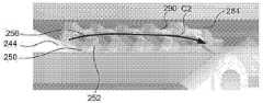
각각의 커넥터(24)는 커넥터에 배치된 복수의 만곡된 부재를 포함한다. 예시적인 배열에서, 각각의 만곡된 부재는 링(30)이고, 복수의 만곡된 부재는 커넥터에 배치된 복수의 링(30)을 포함한다. 도면에 도시된 바와 같이, 5개의 링(30)이 있지만, 다른 예에서는 5개 초과 또는 미만의 링이 있을 수 있다. 링(30)은 전기 전도성이고, 제1 방향(D1)으로 서로 이격될 수 있다. 도면에 도시된 바와 같이, 링(30)은 동일한 거리만큼 제1 방향(D1)으로 서로 이격되어 있지만, 다른 예에서, 인접한 링 사이의 거리는 단일 커넥터(24) 내에서 변할 수 있다. 다른 예들에서, 링(30)의 수, 크기 및 상대적 위치는 변할 수 있다. 링(30)은 각각 금-도금된 금속 또는 다른 전기 전도성 재료일 수 있다. 도 1f에서 알 수 있는 바와 같이, 각각의 링(30)은 길이방향 개구(26) 주위로 연장되는 내부 표면(34) 및 내부 표면의 반대편에 있는 외부 표면(36)을 획정하는 루멘(32)을 가질 수 있다. 각각의 링(30)의 외부 표면(36)의 만곡된 부분(33)은 복수의 횡방향 개구(28) 중 하나에서 각각 노출된다.Each
각각의 링(30)은 하나 이상의 전기 전도성 와이어(38)를 통해 기판(22)의 전기 전도성 부재 중 적어도 하나와 전기적으로 연결될 수 있다. 와이어(38)는 커넥터(24)와 인클로저(20) 사이에서 연장되는 개구(29)를 통해 링(30)으로부터 기판(22)으로 연장될 수 있다. 각각의 커넥터는 길이방향 개구(26) 주위로 연장되고 링(30)의 루멘(32)을 통해 연장되는 하나 이상의 스페이서(39)를 포함할 수 있다. 일부 예들에서, 스페이서(39)는 또한 링(30) 중 인접한 것들 사이에서 연장될 수 있다. 도 1e에서 알 수 있는 바와 같이, 스페이서(39)는 원통형 형상일 수 있다. 스페이서(39)는 링(30)을 서로로부터 그리고 길이방향 개구(26)로부터 전기적으로 절연하도록 구성될 수 있다.Each
전자 시계electronic watch
도 1d에 도시된 바와 같이, 전자 시계(14)는 인클로저(40)를 포함한다. 전자 시계(14)는 인클로저(40) 내에서 연장되는 하나 이상의 기판을 포함할 수 있다. 예를 들어, 도 1f에서 알 수 있는 바와 같이, 기판은 각각 인클로저(40) 내에서 연장되는 상부 인쇄 회로 기판("PCB")(41) 및 하부 PCB(42)를 포함하는 2개의 평행 기판 형태일 수 있다. 상부 PCB(41) 및 하부 PCB(42) 중 하나 또는 둘 모두는 전기 전도성 부재 및 마이크로 프로세서 및 메모리와 같이, 전기 전도성 부재와 전기적으로 연결된 하나 이상의 마이크로 전자 장치를 가질 수 있다. 상이한 수의 기판이 사용될 수 있으며, 기판의 상대적인 위치와 크기가 변할 수 있음을 이해해야 한다.As shown in FIG. 1D , the
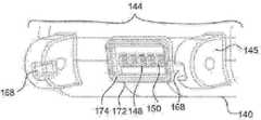
도 1d에서 알 수 있는 바와 같이, 전자 시계(14)는 인클로저(40)의 각각의 단부에 배치된 커넥터(44)를 포함할 수 있다. 각각의 커넥터(44)는 예를 들어, 인클로저(40)로부터 제2 방향(D2)으로 연장되는 하나 이상의 돌출부(45)를 가질 수 있다. 도시된 예에서, 각각의 커넥터(44)는 2개의 돌출부(45)를 갖지만, 다른 예들에서 돌출부의 수, 크기 및 위치는 변할 수 있다. 각각의 돌출부(45)는 제1 방향(D1)에서 돌출부 내로 연장되는 리세스(46)를 가질 수 있다. 리세스(46)는 제1 방향(D1)으로 서로 이격될 수 있다. 커넥터(44)는 제2 방향(D2)에서 커넥터 내로 연장되고, 제1 방향(D1)으로 서로 이격된 복수의 횡방향 개구(48)를 가질 수 있다. 횡방향 개구(48)는 인클로저(40) 내로 직접 연장될 수 있다.As can be seen in FIG. 1D , the
각각의 커넥터(44)는 커넥터에 배치된 복수의 접점(50)을 포함한다. 도면에 도시된 바와 같이, 링(30)과 동일한 수의 5개의 접점(50)이 있지만, 다른 예들에서, 5개 초과 또는 미만의 접점이 있을 수 있다. 접점(50)은 전기 전도성이며, 제1 방향(D1)으로 서로 이격될 수 있다. 도면에 도시된 바와 같이, 접점(50)은 동일한 거리만큼 제1 방향(D1)으로 서로 이격되어 있지만, 다른 예들에서, 인접한 접점 사이의 거리는 단일 커넥터(44) 내에서 변할 수 있다. 다른 예들에서, 접점(50)의 수, 크기 및 상대적 위치는 변할 수 있다. 각각의 접점(50)은 형상 기억을 갖는 스탬핑된 스프링 금속 부재일 수 있어서, 접점의 제1 부분이 접점의 제2 부분에 대해 구부러질 때, 접점이 초기 형상으로 복귀하도록 편향된다. 다른 예들에서, 접점(50)은 형상 기억을 가질 필요가 없고, 접점과 링(30) 사이의 접촉을 유지하는 힘은 인클로저(40) 또는 다른 부품에 의해 제공될 수 있다. 접점(50)은 각각 금-도금된 금속 또는 다른 전기 전도성 재료일 수 있다.Each
각각의 접점(50)은 인클로저(40)에 의해 지지되는 중간 부분(52), 중간 부분에 대해 캔틸레버링된 자유 단부(54) 및 제1 PCB(41)와 제2 PCB(42) 모두에 접촉하는 제2 단부(56)를 가질 수 있다. 각각의 접점(50)의 중간 부분(52)은 각각의 횡방향 개구(48) 내에 배치된 절연 그로밋(57)을 통해 연장될 수 있다. 각각의 절연 그로밋(57)은 접점을 서로로부터 그리고 인클로저(40)로부터 전기적으로 절연하도록 구성될 수 있다. 인클로저(40)의 재료가 접점(50)을 서로 전기적으로 절연할 수 있는 예와 같은 일부 예들에서, 절연 그로밋(57)은 생략될 수 있다. 각각의 접점(50)의 자유 단부(54)는 복수의 횡방향 개구(48) 중 하나에서 각각 노출된다.Each
절연 패드(55)는 각각의 횡방향 개구(48) 내에서 노출되는 인클로저(40)의 표면 상에 제공될 수 있다. 각각의 절연 패드(55)는 자유 단부가 인클로저와 접촉하도록 이동되는 상황에서 인클로저(40)로부터 각각의 접점(50)의 자유 단부(54)를 전기적으로 절연하도록 구성될 수 있다. 각각의 횡방향 개구(48) 내에 노출되는 인클로저(40)의 표면의 재료가 유전체 재료인 예와 같은 일부 예들에서, 추가적인 전기 절연이 필요하지 않을 수 있으므로, 절연 패드(55)가 생략될 수 있다.An insulating
접점(50) 중 적어도 일부는 제1 PCB(41)의 전기 전도성 부재와 제2 PCB(42)의 전기 전도성 부재 사이의 전기적 연결을 제공한다. 도 1f에서 알 수 있는 바와 같이, 각각의 접점(50)의 제2 단부(56)는 제1 PCB(41)의 전기 전도성 부재와 접촉하는 제1 위치(58) 및 제2 PCB(42)의 전기 전도성 부재와 접촉하는 제2 위치(59)를 가질 수 있다.At least some of the
전자 시계 밴드와 전자 시계 사이의 회전 커플링Rotational coupling between the electronic watch band and the electronic watch
도 1a에서 알 수 있는 바와 같이, 전자 시계 밴드(12)는 전자 시계(14)와 결합될 수 있다. 이러한 결합을 달성하기 위해, 각각의 커넥터(24)는 대응하는 커넥터(44)와 정합하도록 구성되어서, 시계 밴드(12)가 전자 시계(14)와 결합될 때, 시계 밴드의 각각의 커넥터는 전자 시계의 대응 커넥터와 회전 가능하게 결합된다.As can be seen in FIG. 1A , the
각각의 커넥터(24) 및 대응 커넥터(44)의 회전 커플링은 도 3c에 도시된 핀(60)과 같은 원통형 핀에 의해 제공될 수 있다. 원통형 핀은 제1 방향(D1)에서 커넥터(44)의 각각의 돌출부(45)의 리세스(46) 내로 연장되고, 대응 커넥터(24)의 길이방향 개구(26)를 완전히 관통할 수 있다. 각각의 커넥터(24)는 인클로저(40)에 대해 원통형 핀을 중심으로 회전할 수 있다. 원통형 핀이 각각의 커넥터(24)를 대응 커넥터(44)와 회전 가능하게 결합할 때, 각각의 링(30)은 접점(50) 중 하나의 대응 자유 단부(54)와 접촉할 것이고, 전자 시계 밴드(12)는 전자 시계(14)와 결합되고, 링은 접점과 전기적으로 연결된다. 이를 위해, 링들(30) 중 인접한 것들 사이의 간격은 인접한 링들 사이의 간격이 동일하거나 변하는지에 관계없이 접점들(50) 중 인접한 것들 사이의 간격과 일치해야 한다.The rotational coupling of each
링(30)과 접점(50) 사이의 물리적 및 전기적 접촉은 접점의 형상 기억의 편향 때문에 유지될 수 있다. 각각의 접점(50)의 자유 단부(54)는 각각의 횡방향 개구(48)를 통해 완전히 연장되고 인클로저(40)의 표면을 약간 넘어 연장되어서, 전자 시계 밴드(12)가 전자 시계(14)와 결합될 때, 접점의 자유 단부가 커넥터(24)의 횡방향 개구(28)로 연장되고, 접점의 자유 단부와 링(30) 사이에 간섭이 있다.Physical and electrical contact between
각각의 접점(50)의 자유 단부(54)는 전자 시계 밴드(12)가 전자 시계(14)와 결합될 때 링들(30) 중 하나와 각각과 접촉할 때 인클로저(40)를 향해 편향되도록 구성된다. 각각의 링(30)이 접점(50)의 자유 단부(54)와 접촉할 때, 캔틸레버링된 자유 단부는 인클로저(40)에 의해 지지되는 중간 부분(52)에 대해 이동한다. 각각의 자유 단부(54)가 중간 부분에 대해 구부러질 때 초기 형상으로 복귀하도록 편향되기 때문에, 접점(50)의 형상 기억은 접점과 링 사이의 접촉을 유지하는 대응 링(30)에 대한 힘을 제공한다. 접점(50) 및 그 자유 단부(54)가 예시적인 형상을 갖는 것으로 도시되었지만, 다른 형상이 가능하다는 것을 이해해야 한다. 예를 들어, 자유 단부(54)는 직선형, 각진형, 곡선형, 루프형 등 일 수 있다.The
링(30)과 접점(50) 사이의 이러한 물리적 및 전기적 접촉은 각각의 커넥터(24)가 대응 커넥터(44)에 대해 회전할 때 유지되고, 그 이유는 커넥터가 서로에 대해 회전할 때 자유 단부(54)가 대응 링(30)의 외부 표면(36)을 따라 슬라이딩할 수 있기 때문이다. 예를 들어, 전자 시계 밴드(12)가 도 1f에 도시된 제1 위치로부터 도 1g에 도시된 제2 위치로 전자 시계(14)에 대해 이동할 때 링(30)과 접점(50) 사이의 물리적 및 전기적 접촉이 유지된다. 도 1f의 제1 위치에서, 기판(22)은 링(30)으로부터 아래쪽으로 연장되고, 접점(50)의 자유 단부(54)는 대응 횡방향 개구(28)의 하부 단부 근처에 위치된다. 도 1g의 제2 위치에서, 기판(22)은 링(30)으로부터 수평으로 연장되고, 접점(50)의 자유 단부는 대응 횡방향 개구(28)의 상부 단부 근처에 위치된다. 제1 위치와 제2 위치 사이에서, 접점(50)의 자유 단부(54)는 대응 횡방향 개구(28) 내에서 상향 방향으로 링(30)의 외부 표면(36)을 따라 슬라이딩한다.This physical and electrical contact between the
시계 밴드의 링의 변형Variation of the ring on the watch band
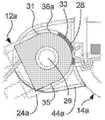
도 2a는 본 발명의 양태에 따른 전자 시계 밴드(12)의 링(30)의 변형을 도시한다. 복수의 만곡된 부재는 본원 명세서에 걸쳐 링-형상 단면을 갖는 것으로 도시된 복수의 링(30)을 포함하는 것으로 위에서 설명되었지만, 그럴 필요는 없다. 도 2a의 예에서, 전자 시계 밴드(12a)는 링(30)을 대체하는 만곡된 부재(31)를 갖는 만곡된 부재를 갖는다. 만곡된 부재(31)는 각각 금-도금된 금속 또는 다른 전기 전도성 재료일 수 있다. 만곡된 부재(31)는 각각 시계 밴드의 복수의 횡방향 개구(28) 중 하나에서 각각 노출되는 외부 표면(36a)의 만곡된 부분(33)을 갖는다. 만곡된 부재(31)는 각각 도 2a의 예에 도시된 바와 같이 직사각형의 부분과 같은 임의의 형상 또는 도 1a 내지 도 1g의 링(30)과 유사한 다른 만곡된 부분을 가질 수 있는 비-노출 부분(35)을 가질 수 있다. 단일 커넥터의 만곡된 부재(31) 각각은 동일한 단면 형상 또는 상이한 단면 형상을 가질 수 있고, 전자 시계 밴드(12a)의 하나의 커넥터의 만곡된 부재는 전자 시계 밴드의 다른 커넥터와 상이한 형상 조합을 가질 수 있다.2A shows a variant of the
만곡된 부재(31)의 단면 형상에 관계없이, 만곡된 부재는 길이방향 개구(26) 주위로 적어도 부분적으로 연장될 수 있어서, 도 3c의 핀(60)과 같은 핀은 전자 시계 밴드(12a)의 커넥터(24a)를 전자 시계(14a)의 커넥터(44a)와 회전 가능하게 결합시키기 위해 길이방향 개구를 통해 연장될 수 있다. 만곡된 부재(31)와 같이, 링의 단면 형상의 변형은 본원 명세서에 설명된 링 예들 중 임의의 것에 적용될 수 있다.Regardless of the cross-sectional shape of the
커넥터의 변형Deformation of the connector
도 2b는 본 발명의 양태에 따른 도 1a 내지 도 1g의 커넥터(24 및 44)의 변형을 도시한다. 이 예는 링 또는 만곡된 커넥터가 시계에 위치되고 스프링 커넥터가 밴드에 위치되는 것을 제외하고는 도 1a 내지 도 1g에 도시된 예와 유사하다. 이 예에서, 전자 시계 밴드(12b)는 도 1a 내지 도 1g의 전자 시계(14)의 커넥터(44)와 유사한 커넥터(44b)를 갖고, 전자 시계(14b)는도 1a-1g의 전자 시계 밴드(12)의 커넥터(24)와 유사한 커넥터(24b)를 갖는다. 밴드의 커넥터(44b)는 제1 방향(D1)으로 이격된 돌출부(45b)를 갖고, 시계의 커넥터(24b)는 제1 방향에서 서로 이격된 커넥터의 둥근 부분에서 복수의 횡방향 개구(28)를 통해 노출된 링(30b)을 포함한다. 커넥터(24b)는 횡방향 개구(28) 중 하나에서 각각 노출된 둥근 부분(33)을 갖는 링(30b)을 갖는다. 링(30b)은 하나 이상의 전기 전도성 와이어(38b)를 통해 전자 시계(14b)의 하나 이상의 PCB와 전기적으로 연결될 수 있다.2B illustrates a variation of the
커넥터(44b)는 중간 부분(52)에 대해 캔틸레버링된 자유 단부(54) 및 시계 밴드(12b)의 기판과 전기적으로 연결될 수 있는 제2 단부(56)를 갖는 접점(51)을 갖는다. 접점(51)은 시계 밴드(12b) 내에서 하나 이상의 기판과 전기적으로 연결될 수 있고, 도 1a 내지 도 1g의 접점(50)의 형상과 같은 다양한 단면 형상, 도 2c 내지 도 2f에서 후술될 접점(50a, 50b, 50c)의 형상 또는 루프, 곡선 등과 같은 다양한 다른 형상을 가질 수 있다. 단지 예로서, 접점의 자유 단부(54)는 각을 이루거나, 만곡되거나, 루프형이거나, 직선이거나 또는 횡방향 개구(28)를 통해 링(30b)과 결합하도록 구성된 임의의 다른 형상을 취할 수 있다. 단일 커넥터(44b)의 접점(51) 각각은 동일한 단면 형상 또는 상이한 단면 형상을 가질 수 있고, 전자 시계 밴드(12b)의 하나의 커넥터의 접점은 전자 시계 밴드의 다른 커넥터와 상이한 형상 조합을 가질 수 있다.The
전자 시계 밴드 또는 전자 시계에 위치하는 링 또는 접점의 변형은 본원 명세서에 설명된 임의의 예에 적용될 수 있다. 일부 예들에서, 단일 전자 시계 밴드는 일 단부에 커넥터(24) 및 다른 단부에 커넥터(44b)를 가질 수 있고, 단일 대응 전자 시계는 일 단부에 커넥터(44) 및 다른 단부에 커넥터(24b)를 가질 수 있다.Variations of rings or contacts located on an electronic watch band or electronic watch may be applied to any of the examples described herein. In some examples, a single electronic watch band may have
전자 시계 접점의 변형Deformation of electronic watch contacts
도 2c 내지 도 2e는 본 발명의 양태에 따른 전자 시계(14)의 접점(50)의 변형을 도시한다. 도 2c는 도 1f의 접점(50)과 유사한 형상을 갖는 접점(50a)을 도시하지만, 접점은 제1 PCB(41)와 전기적으로 연결되고 제2 PCB(42)와는 연결되지 않는다. 접점(50a)은 제1 PCB(41)의 전기 전도성 패드(62)와 접촉하지만, 접점이 제2 PCB(42)와 접촉하는 위치에서, 제2 PCB는 제2 PCB의 유전체 기판의 일부와 같은 전기 절연 특징부를 갖는다. 따라서, 접점(50a)이 물리적으로 제2 PCB(42)와 접촉하더라도, 접점은 제2 PCB의 전기 전도성 부재와 전기적으로 절연된다.2c-2e show a variant of the
도 2d는 또한 접점(50)과 유사한 형상이지만 더 짧은 제2 단부(56b)를 갖는 접점(50b)을 도시한다. 접점(50b)의 제2 단부(56b)는 제1 PCB(41)와 물리적 및 전기적으로 접촉하기에 충분히 길지만, 제2 PCB(42)와 접촉하기에는 충분히 길지 않다. 따라서, 전자 시계 밴드(12)가 전자 시계(14)와 결합되고 링(30)이 대응 접점과 결합될 때, 접점(50b)은 대응 링과 제1 PCB(41) 사이의 전기적 연결만을 제공한다.FIG. 2D also shows
도 2e는 접점(50)과 유사한 형상이지만 더 짧은 자유 단부(54c)를 갖는 접점(50c)을 도시한다. 접점(50c)의 제2 단부(56c)는 제1 PCB(41)를 제2 PCB(42)와 물리적 및 전기적으로 접촉시키기에 충분히 길지만, 접점은 대응 링(30)과 접촉하기에는 충분히 길지 않다. 따라서, 전자 시계 밴드(12)가 전자 시계(14)와 결합될 때, 접점(50c)은 제1 PCB(41)와 제2 PCB(42) 사이에 전기적 연결을 제공하지만, 접점은 대응 링(30)과 이격되어 있으므로 접점은 대응 링과 제1 PCB 또는 제2 PCB 사이에 전기적 연결을 제공하지 않는다.2E shows contact 50c having a similar shape to contact 50 but with a shorter free end 54c. The second end 56c of the contact 50c is long enough to physically and electrically contact the
도 2f는 단일 커넥터(44d)에서 결합된 접점(50, 50b, 50c)의 예를 도시한다. 전자 시계 밴드의 커넥터(24)가 전자 시계의 커넥터(44d)와 결합될 때, 접점(50)은 대응 링(30)과 제1 PCB(41)(도 2f에서 투명함) 및 제2 PCB(42) 둘 모두 사이에 전기적 연결을 제공하기에 충분히 길다. 접점(50b)은 제2 PCB(42)에 도달하지 않으므로, 접점은 대응 링(30)과 제1 PCB(41) 사이의 전기적 연결만을 제공한다. 접점(50c)은 대응 링(30)에 도달하지 않으므로, 접점은 제1 PCB(41)와 제2 PCB(42) 사이의 전기적 연결만을 제공한다.Figure 2f shows an example of
비-회전 커넥터 변형Non-rotating connector variant
도 3a 내지 도 3d는 본 발명의 양태에 따른 도 1a 내지 도 1f의의 전자 시계 시스템(10)의 변형인 예시적인 전자 시계 시스템(110)을 도시한다. 전자 시계 시스템(110)은 후술하는 특징부를 제외하고는 전자 시계 시스템(10)과 동일할 수 있다. 도 3d에서 알 수 있는 바와 같이, 전자 시계 시스템(110)은 전자 시계(114)와 결합된 전자 시계 밴드(112)를 포함한다.3A-3D illustrate an exemplary
시계 밴드(112)는 인클로저(120)의 각각의 단부에 배치된 커넥터(124)를 포함하고, 전자 시계(114)는 인클로저(140)의 각각의 단부에 배치된 커넥터(144)를 포함한다. 커넥터(124) 및 커넥터(144)는 전술한 커넥터(24 및 44)와 동일하지만, 시계 밴드(112)가 전자 시계(114)와 결합될 때 서로 정합하도록 구성된 연동 특징부가 추가됨에 따라 연동 특징부는 서로에 대한 커넥터의 회전을 방지하도록 구성된다.
연동 특징부는 커넥터(124)의 측면 표면(166)으로부터 제1 방향(D1)으로 연장되는 2개의 탭(164) 및 제1 및 제2 방향(D1 및 D2) 모두에서 커넥터(144)의 각각의 돌출부(145)로 연장되는 2개의 리세스(168)를 포함한다. 탭(164) 및 리세스(168) 각각은 직사각형 단면을 가지며, 제1 및 제2 방향(D1 및 D2) 각각에 수직인 제3 방향(D3)에서의 탭의 높이는 제3 방향에서의 리세스의 높이와 대략 동일하거나 약간 작아서, 탭(164)이 리세스(168)와 결합하도록 구성된다. 탭(164) 및 리세스(168)의 직사각형 단면은 탭이 리세스에 결합될 때 커넥터들(124 및 144)을 서로 회전 가능하게 고정하도록 구성된다.Interlocking features include two
연동 특징부는 또한 커넥터(124)로부터 제2 방향(D2)으로 연장되고 복수의 횡방향 개구(128) 주위로 연장되는 립(170), 커넥터(144)로부터 제2 방향(D2)으로 연장되고 복수의 횡방향 개구(148) 주위로 연장되는 립(172) 및 립(172)의 내부 표면 주위로 연장되는 개스킷(174)을 포함한다. 립(170)의 외부 표면의 윤곽은 개스킷(174)의 내부 표면의 윤곽과 대략 동일하여서, 시계 밴드(112)가 전자 시계(114)와 결합될 때, 립(170)이 립(172) 내로 삽입되고, 개스킷은 립들(170 및 172) 사이에 수밀 밀봉을 제공하도록 구성된다. 도 3d에서 알 수 있는 바와 같이, 개스킷(174)은 시계 밴드(112)가 전자 시계(114)와 결합될 때 링(130)과 접점(150) 사이의 인터페이스 주위에 수밀 밀봉을 제공하도록 또한 구성된다.The interlocking features also include a
전술한 연동 특징부는 도 3a 내지 도 3d에 도시된 특정 예로부터 변경될 수 있다. 예를 들어, 커넥터(144)의 돌출부(145) 상에 탭이 제공될 수 있고, 커넥터(124) 내로 연장되는 보완 리세스가 제공될 수 있다. 또한, 개스킷(174)은 립(170)의 외부 표면 주위로 연장되어 제공될 수 있다. 다른 변형에서, 립들(170 및 172)의 윤곽은 반전될 수 있고, 개스킷(174)은 립(172)의 내부 표면 주위로 연장되어 제공될 수 있어서, 립(172)의 외부 표면의 윤곽이 개스킷(174)의 내부 표면의 윤곽과 거의 동일하고, 시계 밴드(112)가 전자 시계(114)와 결합될 때 립(172)이 립(170) 내로 삽입된다.The aforementioned interlocking features may vary from the specific examples shown in FIGS. 3A-3D . For example, a tab may be provided on
리셉터클 마운팅 변형Receptacle Mounting Variations
도 4a 내지 도 4h는 본 발명의 양태에 따른 도 1a 내지 도 1f의 전자 시계 시스템(10)의 변형인 예시적인 전자 시계 시스템(210)을 도시한다. 도 4a 및 도 4c에서 알 수 있는 바와 같이, 전자 시계 시스템(210)은 시계 밴드를 전자 시계와 결합하도록 구성된 리셉터클(216)을 통해 전자 시계(214)와 결합된 전자 시계 밴드(212)를 포함한다. 리셉터클 또는 리셉터클 마운트는 예를 들어, 바요넷 마운트 또는 다른 유형의 마운트를 포함할 수 있다.4A-4H depict an exemplary
시계 밴드watch band
전자 시계 밴드(212)는 전술한 인클로저(20) 및 기판(22)과 유사한 인클로저(220) 및 기판(222)을 포함한다. 시계 밴드(212)는, 도 4g에서 알 수 있는 바와 같이, 횡방향 개구(228)가 돌출부(245)에 대한 접점(250)의 중심을 벗어난 위치를 수용하기 위해 횡방향 개구(28)에 비해 커넥터(224)의 둥근 부분을 따라 중심에서 벗어난 원주 위치에 있는 것을 제외하고는 전술한 커넥터(24)와 유사한 인클로저(220)의 각각의 단부에 배치된 커넥터(224)를 갖는다. 각각의 커넥터(224)는 전술한 링(30)과 유사한 커넥터에 배치된 복수의 링(230)(도 4g)을 포함한다. 각각의 링(230)의 외부 표면(236)의 만곡된 부분(233)은 복수의 횡방향 개구(228) 중 하나에서 각각 노출된다.
리셉터클receptacle
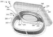
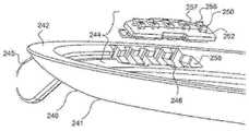
리셉터클(216)은 전자 시계(214)와 시계 밴드(212) 사이의 커플링과 관련하여 전술한 것과 유사한 방식으로, 도 3c의 핀(60)과 같은 핀에 의해 시계 밴드(212)에 회전 가능하게 결합될 수 있다. 도 4c에서 알 수 있는 바와 같이, 리셉터클(216)은 원형 레지(240) 형태의 인클로저를 포함한다. 원형 레지(240)는 하부 표면(241) 및 하부 표면의 반대편에 있는 상부 표면(242)을 가질 수 있다.
리셉터클(216)은 원형 레지의 각각의 측면에서 원형 레지(240) 내에 배치된 중간 커넥터(244)를 포함할 수 있다. 각각의 중간 커넥터(244)는 예를 들어, 인클로저(240)로부터 제2 방향(D2)으로 연장되는 하나 이상의 돌출부(245)를 가질 수 있다. 도시된 예에서, 각각의 중간 커넥터(244)는 2개의 돌출부(245)를 갖지만, 다른 예들에서 돌출부의 수, 크기 및 위치는 변할 수 있다. 각각의 돌출부(245)는 제1 방향(D1)에서 돌출부 내로 연장되는 리세스(246)를 가질 수 있다. 리세스(246)는 제1 방향(D1)으로 서로 이격될 수 있다. 중간 커넥터(244)는 제2 방향(D2)에서 중간 커넥터로 연장되고, 제1 방향(D1)으로 서로 이격된 복수의 횡방향 개구(248)(도 4d 및 도 4e)를 가질 수 있다. 횡방향 개구들(48)은 원형 레지(240) 내로 직접 연장될 수 있다.
각각의 중간 커넥터(244)는 중간 커넥터에 배치된 복수의 접점(250)을 포함한다. 도면에 도시된 바와 같이, 링(230)과 동일한 수의 5개의 접점(250)이 있지만, 다른 예들에서, 5개 초과 또는 미만의 링이 있을 수 있다. 접점(250)은 전기 전도성, 예를 들어, 금-도금된 금속 또는 다른 전기 전도성 재료일 수 있다. 각각의 접점(250)은 중간 커넥터(244)에 의해 지지되는 중간 부분(252), 원형 레지의 하부 표면(241)에서 노출되는 제1 단부(254) 및 원형 레지의 상부 표면(242)에서 노출되는 제2 단부(256)를 가질 수 있다. 각각의 접점(250)의 제1 단부(254)는 중간 부분(252)에 대해 캔틸레버링 될 수 있고, 각각의 접점의 제2 단부(256)는 오목한 형상을 가질 수 있으며, 또한 중간 부분에 대해 캔틸레버링될 수 있다. 각각의 접점(250)은 형상 기억을 갖는 스탬핑된 스프링 금속 부재일 수 있어서, 접점(256)의 제1 단부(254) 또는 제2 단부(256)가 접점의 중간 부분(252)에 대해 구부러질 때, 접점이 초기 형상으로 복귀하도록 편향된다. 다른 예들에서, 접점(250)은 형상 기억을 가질 필요가 없고, 접점과 링(230) 및/또는 핀(290) 사이의 접촉을 유지하는 힘은 원형 레지(240) 또는 다른 부품에 의해 제공될 수 있다. 다른 예들에서, 접점(250)의 수, 크기 및 상대적 위치는 변할 수 있다.Each
각각의 접점(250)의 제1 단부(254)는 복수의 횡방향 개구(248) 중 하나에서 각각 원형 레지(240)의 하부 표면(241)에서 노출되고, 각각의 접점의 제2 단부(256)는 원형 레지의 상부 표면(242)에서 노출된다. 각각의 접점(250)은 리셉터클(216) 내로 연장되는 대응 리세스(258) 내에 수용되는 절연 삽입물(257)에 고정될 수 있고 이를 통해 연장될 수 있다. 횡방향 개구(248)는 적어도 부분적으로 절연 삽입물(257)에 의해 획정될 수 있다. 절연 삽입물(257)은 접점(250)을 서로로부터 그리고 원형 레지(240)로부터 전기적으로 절연하도록 구성될 수 있다. 절연 삽입물(257)은 각각의 접점(250)의 중간 부분(252)을 지지할 수 있고, 각각의 접점의 제1 단부(254) 및 제2 단부(256)는 절연 삽입물에 대해 캔틸레버링될 수 있다. 원형 레지(240)의 재료가 접점(250)을 서로 전기적으로 절연할 수 있는 예와 같은 일부 예들에서, 절연 삽입물(257)은 생략될 수 있다.A
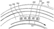
접점(250)은 서로 이격될 수 있다. 접점(250)의 제1 단부(254)는 도 4e에 도시된 바와 같이, 제1 방향(D1)으로 서로 이격될 수 있는 반면, 접점의 제2 단부(256)는 도 4b에 도시된 바와 같이, 제2 원주 방향(C2)으로 서로 이격될 수 있다. 접점(250)의 제2 단부(256) 중 특정 단부의 정확한 형상 및 길이는 이들이 제2 원주 방향(C2)을 따라 이격되는 것을 보장하기 위해 서로 변경될 수 있다.The
전자 시계electronic watch
전자 시계(214)는 인클로저(280)를 포함한다. 전자 시계(214)는 인클로저(280) 내에서 연장되는 하나 이상의 기판을 포함할 수 있다. 도 4g에서 알 수 있는 바와 같이, 기판은 인클로저(280) 내에서 연장되는 PCB(281)를 포함할 수 있다. 상이한 수의 기판이 사용될 수 있고 기판의 위치 및 크기가 변경될 수 있음을 이해해야 한다. 도 4c에 도시된 바와 같이, 인클로저(280)의 하부 표면(282)은 원형 레지(240)의 상부 표면(242)의 윤곽과 정합하도록 구성된 원형 윤곽을 가질 수 있다.The
전자 시계(214)는 인클로저(280)의 하부 표면(282)의 각각의 단부에 배치된 커넥터(284)를 포함할 수 있다. 각각의 커넥터(284)는 커넥터에 배치된 복수의 핀(290)을 포함한다. 핀(290)은 각각 전기 전도성, 예를 들어, 금-도금된 금속 또는 다른 전기 전도성 재료일 수 있다. 각각의 핀(290)은 제2 인클로저의 하부 표면에 노출된 자유 단부(292)를 가질 수 있다. 핀(290)의 자유 단부(292) 각각은 방위각으로 신장된 형상을 가질 수 있고, 인클로저(280)의 하부 표면(282) 아래로 돌출할 수 있다. 도면에 도시된 바와 같이, 접점(250) 및 링(230)과 동일한 수의 5개의 핀(290)이 있지만, 다른 예들에서, 5개 초과 또는 미만의 핀이 있을 수 있다. 핀(290)은 PCB(281)의 전기 전도성 부재와 전기적으로 연결될 수 있으며, PCB(281)는 마이크로 프로세서 및 메모리와 같이, 전자 시계(214) 내에 배치된 하나 이상의 마이크로 전자 장치와 전기적으로 연결될 수 있다.Electronic watch 214 can include
핀(290)은 제2 원주 방향(C2)으로 서로 이격될 수 있다. 도 4f에 도시된 바와 같이, 핀(290)은 동일한 거리만큼 제2 원주 방향(C2)으로 서로 이격될 수 있지만, 도 4h에 도시된 도식적인 예와 같은 다른 예들에서는, 인접한 핀(290) 사이의 원주 거리는 단일 커넥터(284) 내에서 변할 수 있다. 제2 원주 방향(C2)에서 핀(290)의 간격은 제2 원주 방향에서 접점(250)의 제2 단부(256)의 간격과 동일해야 한고, 이는 전자 시계(214)가 리셉터클(216)에 결합될 때, 핀(290)과 접점의 제2 단부가 서로 정합하도록 구성되기 때문이다. 도 4g에서 알 수 있는 바와 같이, 각각의 핀(290)은 인클로저(280) 내로 연장된 대응 리세스(296) 내에 수용되는 절연 삽입물(294)에 고정 될 수 있고, 절연 삽입물(294)을 통해 연장될 수 있다. 절연 삽입물(294)은 핀(290)을 서로로부터 그리고 인클로저(280)로부터 전기적으로 절연하도록 구성될 수 있다.The
회전 커플링swivel coupling
도 4g에서 알 수 있는 바와 같이, 전자 시계 밴드(212)는 시계 밴드와 전자 시계 사이의 중간 물리적 및 전기적 연결을 제공하는 리셉터클(216)을 통해 전자 시계(214)와 결합될 수 있다.As can be seen in FIG. 4G ,
밴드와 리셉터클 사이의 커플링Coupling between band and receptacle
전자 시계 밴드(212)와 리셉터클(216) 사이의 결합은 전술한 전자 시계 밴드(12)와 전자 시계(14) 사이의 결합과 유사하다. 이러한 결합을 달성하기 위해, 각각의 커넥터(224)는 대응 중간 커넥터(244)와 정합하도록 구성되어서, 시계 밴드(212)가 리셉터클(216)과 결합될 때, 시계 밴드의 각각의 커넥터는 리셉터클의 대응 중간 커넥터와 회전 가능하게 결합된다. 각각의 커넥터(224)와 대응 중간 커넥터(244)의 회전 커플링은 도 3c에 도시된 핀(60)과 같은 원통형 핀에 의해 제공될 수 있다.The coupling between the
원통형 핀이 각각의 커넥터(224)를 대응 중간 커넥터(244)와 회전 가능하게 결합시킬 때, 각각의 링(230)은 접점(250) 중 하나의 대응 제1 단부(254)와 접촉할 것이고, 전자 시계 밴드(212)가 전자 시계(216)와 결합될 때, 링은 접점과 전기적으로 연결된다. 이를 위해, 링들(230) 중 인접한 것들 사이의 간격은 인접한 링들 사이의 간격이 동일하거나 변하는지에 관계없이 접점들(250) 중 인접한 것들 사이의 간격과 일치해야 한다.When the cylindrical pin rotatably engages each
하나 이상의 링(230)과 접점(250) 사이의 물리적 및 전기적 접촉은 접점의 형상 기억의 편향 때문에 유지될 수 있다. 하나 이상의 접점(250)의 제1 단부(254)는 각각의 횡방향 개구(248)를 통해 완전히 연장되고, 원형 레지(240)의 하부 표면(241)을 약간 넘어 연장되어서, 전자 시계 밴드(212)가 리셉터클(216)과 결합될 때, 접점의 제1 단부는 커넥터(224)의 횡방향 개구(228)로 연장되고, 접점의 제1 단부와 링(230) 사이에 간섭이 있다. 각각의 링(230)이 접점(250)의 제1 단부(254)와 접촉할 때, 캔틸레버링된 제1 단부는 원형 레지(240)에 의해 지지되는 중간 부분(252)에 대해 이동한다. 각각의 제1 단부(254)가 중간 부분(252)에 대해 구부러질 때 초기 형상으로 복귀하도록 편향되기 때문에, 접점(250)의 형상 기억은 접점과 링 사이의 물리적 및 전기적 접촉을 유지하는 대응 링(230)에 대한 힘을 제공한다.Physical and electrical contact between the one or
시계와 리셉터클 사이의 커플링Coupling between clock and receptacle
전자 시계(214)와 리셉터클(216) 사이의 결합은, 제2 원주 방향(C2)에서 접점(250)으로부터 핀(290)이 이격되어 있는 제1 결합 위치에서 인클로저(280)의 하부 표면(282)이 원형 레지(240)에 결합할 때까지 리셉터클로 전자 시계를 병진이동시킴으로써 그리고 이어서 제2 원주 방향에서 모든 핀이 접점 중 하나와 각각 정렬되는 제2 위치에 전자 시계 및 리셉터클이 있을 때까지 리셉터클에 대해 전자 시계를 회전시킴으로써 달성된다.Engagement between the
전자 시계(214)와 리셉터클(216)이 제2 결합 위치에 있으면, 핀(290)은 접점(250)과 물리적으로 결합되고 전기적으로 연결되며, 인클로저(280)의 하부 표면(282)으로부터 연장되는 탭(286)과 원형 레지(240)의 하부 표면(241)으로부터 연장되는 탭(249) 사이의 결합이 시계의 병진 이동으로 인해 리셉터클로부터 전자 시계가 분리되는 것을 방지할 것이다. 이를 위해, 핀들(290) 중 인접한 것들 사이의 간격은 이하에서 더욱 상세하게 설명되는 바와 같이, 인접한 핀들 사이의 간격이 동일하거나 변하는지에 관계없이 접점들(250) 중 인접한 것들 사이의 간격과 일치해야 한다.When
핀(290)의 자유 단부(292) 및 접점(250)의 제2 단부(256)의 구조는 충분한 회전력이 제공되지 않는 한, 전자 시계의 회전으로 인해 전자 시계(214)가 리셉터클(216)로부터 분리되는 것을 방지하도록 구성된다. 핀(290)과 접점(250) 사이의 물리적 및 전기적 접촉은 접점의 형상 기억의 편향 및 핀과 접점의 상보적인 형상으로 인해 유지될 수 있다. 전자 시계(214)와 리셉터클(216) 사이의 결합 전에, 접점(250) 각각의 제2 단부(256)는 원형 레지(240)의 상부 표면(242)보다 약간 위로 연장된다. 전자 시계(214)가 리셉터클(216)과 결합될 때, 각각의 핀(290)의 방위각으로 신장된 자유 단부(292)는 접점(250)의 제2 단부(256)의 오목한 부분으로 연장되고, 접점의 제2 단부와 핀 사이에 간섭이 있다.The structure of the
각각의 링(290)이 접점(250)의 제2 단부(256)와 접촉할 때, 캔틸레버링된 제2 단부는 원형 레지(240)에 의해 지지되는 중간 부분(252)에 대해 이동하여서, 제2 단부가 중간 커넥터(244)로 편향된다. 각각의 제2 단부(256)가 중간 부분(252)에 대해 구부러질 때 초기 형상으로 복귀하도록 편향되기 때문에, 접점(250)의 형상 기억은 접점과 핀 사이의 물리적 및 전기적 접촉을 유지하는 대응 핀(290)에 대한 힘을 제공한다. 핀(290)과 접점(250) 사이의 이 힘은 핀과 접점 사이의 힘 및 간섭을 극복하기에 충분한 회전력이 제공되지 않는 한, 전자 시계의 회전으로 인해 전자 시계(214)가 리셉터클(216)로부터 분리되는 것을 방지하도록 구성된다.When each
시계 및 리셉터클의 접점 및 핀 위치Contacts and Pin Locations on Watches and Receptacles
전자 시계(214)가 제1 결합 위치로부터 제2 결합 위치를 향해 리셉터클(216)에 대해 회전되는 동안, 단락이 발생하는 것을 방지하기 위해, 제2 결합 위치에 도달하기 전에 임의의 단일 순간 동안 핀(290) 중 임의의 것과 접점(250) 중 임의의 것 사이에 단일 물리적 및 전기적 연결만이 존재하는 것이 바람직하다. 이는 특정 규칙 세트에 따라 접점(250)의 제2 단부(256)를 서로 불균일하게 이격시키고 동일한 불균일한 간격을 제2 원주 방향(C2)으로 핀(290)에 적용함으로써 달성될 수 있다. 이러한 간격의 일 예가 도 4h에 도시되어 있고, 도시된 중간 위치(제1 결합 위치와 제2 결합 위치 사이)에서, 핀(290) 중 임의의 것과 접점(250) 중 임의의 것 사이의 유일한 물리적 및 전기적 연결은 제3 핀(290c)과 제2 접점(250b) 사이에 있다.While the
전술한 소망하는 불균일 간격을 달성할 수 있는 특정 규칙 세트는 제1, 제2, 제3, 제4 및 제5 접점(250a, 250b, 250c, 250d 및 250e) 간의 관계 및 A, B, C 및 D인 접접 중 인접한 것들 사이의 각도 거리로 표현될 수 있다. A가 B + C와 동일하지 않고, B가 C + D와 동일하지 않으며, D가 B + C와 동일하지 않다면, 수학적으로 제2 결합 위치가 도달되기 전 임의의 단일 순간 동안 핀(290) 중 임의의 것과 접점(250) 중 임의의 것 사이의 단일 물리적 및 전기적 연결만 있을 것이라고 보장할 수 있다. 도 4h에 도시된 특정 예에서, A = 25°, B = 10°, C = 20°, D = 40°이므로 위의 식이 충족되고, 바람직한 단락 방지 조건이 달성된다.A specific set of rules that can achieve the desired non-uniform spacing described above is the relationship between the first, second, third, fourth and
다른 변형other variations
위의 예시적인 시스템은 모두 전자 시계 및 전자 시계 밴드를 포함하는 회전 커플링을 포함하지만, 전술한 회전 가능한 전기 링-접점 커플링은 다양한 회전 커플링 예에서 구현될 수 있다.While the above exemplary systems all include rotational couplings that include electronic watches and electronic watch bands, the aforementioned rotatable electrical ring-contact couplings may be implemented in a variety of rotational coupling examples.
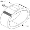
예를 들어, 도 5는 전자 시계 밴드(12)가 통합 디스플레이 스크린을 갖지 않는 전자 활동 모듈(314)에 결합될 수 있는 예시적인 전자 활동 모듈 시스템(300)을 도시한다. 전자 활동 모듈(314)은 EKG 모듈과 같은 스마트 의료 모듈일 수 있다. 전자 시계 밴드(12)는 추가 배터리 용량 및/또는 시계 밴드와 스마트 폰 사이의 무선 통신을 전자 활동 모듈(314)에 제공할 수 있다. 이러한 활동 모듈 시스템(300)에서, 스마트 폰은 사용자가 전자 활동 모듈(314)과 통신하기 위한 디스플레이 및 인터페이스 역할을 할 수 있다.For example, FIG. 5 depicts an exemplary electronic
도 6은 전자 시계 밴드(12)가 통합 디스플레이 스크린 또는 통합 스마트 시계 특징부를 가지지 않을 수 있는 아날로그 시계(414)에 결합될 수 있는 예시적인 전자 아날로그 시계 시스템(400)을 도시한다. 전자 아날로그 시계 시스템(400)은 사용자가 스타일리시한 및/또는 고가의 아날로그 시계를 착용하는 것을 가능하게 할 수 있고, 전자 시계 밴드(12)는 스마트 시계 특징을 가능하게 할 수 있다. 전자 시계 밴드(12)는 의료 특징, 스포츠 특징, 결제 특징 등과 같은 활동별 특징을 아날로그 시계(414)에 제공할 수 있다. 전자 시계 밴드(12)는 스마트 폰과 무선으로 통신할 수 있다. 이러한 전자 아날로그 시계 시스템(400)에서, 스마트 폰은 사용자가 시계 밴드의 활동별 특징을 모니터링 및/또는 제어하기 위해 전자 시계 밴드(12)와 통신하는 디스플레이 및 인터페이스 역할을 할 수 있다.6 illustrates an example electronic
도 7은 컴퓨터 키보드(520)를 디스플레이 스크린(530)과 회전 가능하게 결합하는 전자 힌지(510)에서 전술한 회전 가능한 전기 링-접점 커플링이 구현될 수 있는 예시적인 랩탑 시스템(500)을 도시한다. 이러한 랩탑 시스템(500)은 컴퓨터 키보드(520)가 디스플레이 스크린(530)으로부터 선택적으로 부착 및 분리되는 것을 허용하면서 전자 신호가 회전 전자 힌지(510)를 통과하게 할 수 있다.FIG. 7 shows an
예를 들어, 랩탑 시스템(500)은 컴퓨터 키보드(520)에 부착된 커넥터(44)(도 1d) 중 대응하는 커넥터 및 디스플레이 스크린(530)에 부착된 커넥터(24)(도 1b) 중 대응하는 커넥터를 각각 포함하는 하나 이상의 전자 힌지(510)를 가질 수 있다. 랩탑 시스템(500)은 커넥터(44 및 24) 쌍 사이의 커플링을 제공할 수 있는 도 3c에 도시된 핀(60)과 같은 하나 이상의 부재 또는 그 일부를 연장 또는 수축시키도록 구성된 토글을 포함할 수 있다. 이러한 핀(60) 또는 그 일부가 수축되면, 컴퓨터 키보드(520)와 디스플레이 스크린(530)이 서로 분리될 수 있고, 이러한 핀 또는 그 일부가 연장되면, 컴퓨터 키보드와 디스플레이 스크린이 서로 다시 결합될 수 있다.For example,
달리 언급되지 않는 한, 전술한 대안적인 예들은 상호 배타적이지 않으며, 독특한 이점을 달성하기 위해 다양한 조합으로 구현될 수 있다. 전술한 특징의 이러한 및 다른 변형 및 조합은 청구항에 의해 정의된 발명을 벗어나지 않고 활용될 수 있으므로, 실시예들에 대한 전술한 설명은 청구항에 의해 정의된 발명의 제한이 아닌 예시의 방식으로 취해져야 한다. 또한, 본원 명세서에 설명된 예들뿐만 아니라 "예를 들어", "포함하는" 등과 같이 구절로 표현된 조항은 특정 예들에 대한 청구항의 발명을 제한하는 것으로 해석되어서는 안되고; 오히려, 예들은 많은 가능한 실시예들 중 하나만을 예시하기 위한 것이다. 또한, 다른 도면에서 동일한 도면부호는 동일하거나 유사한 부재를 식별할 수 있다.Unless otherwise stated, the alternative examples described above are not mutually exclusive and may be implemented in various combinations to achieve unique advantages. Since these and other variations and combinations of the foregoing features may be utilized without departing from the invention defined by the claims, the foregoing description of the embodiments should be taken by way of example and not limitation of the invention defined by the claims. do. Further, the examples set forth herein, as well as clauses expressed in phrases such as “for example,” “comprising,” etc., should not be construed as limiting the claimed subject matter to the specific examples; Rather, the examples are intended to illustrate only one of many possible embodiments. Also, the same reference numerals in different drawings may identify the same or similar members.
Claims (17)
Translated fromKorean전기 전도성 부재를 수용하는 제1 인클로저 및 상기 제1 인클로저의 단부에 배치된 제1 커넥터를 포함하는 제1 부품; 및
제2 인클로저 및 상기 제2 인클로저의 단부에 배치된 제2 커넥터를 포함하는 제2 부품을 포함하며,
제1 커넥터는 제2 커넥터와 정합하도록 구성되어서, 제1 부품이 제2 부품과 결합될 때, 제1 커넥터는 제2 커넥터와 회전 가능하게 결합되는 것을 특징으로 하는 전자 힌지 시스템.With an electronic hinge system,
a first part comprising a first enclosure accommodating an electrically conductive member and a first connector disposed at an end of the first enclosure; and
a second part comprising a second enclosure and a second connector disposed at an end of the second enclosure;
The electronic hinge system of claim 1 , wherein the first connector is configured to mate with the second connector, such that when the first component is engaged with the second component, the first connector is rotatably engaged with the second connector.
제2 인클로저는 복수의 제2 전기 전도성 부재를 수용하고, 제1 커넥터 및 제2 커넥터는 정합될 때 제1 인클로저의 전기 전도성 부재와 제2 인클로저의 복수의 제2 전기 전도성 부재 사이에 전기적 연결을 형성하는 것을 특징으로 하는 전자 힌지 시스템.According to claim 1,
The second enclosure receives a plurality of second electrically conductive members, and the first connector and the second connector, when mated, establish an electrical connection between the electrically conductive member of the first enclosure and the plurality of second electrically conductive members of the second enclosure. An electronic hinge system, characterized in that forming.
제1 부품은 전자 시계 밴드이고, 제2 부품은 전자 시계인 것을 특징으로 하는 전자 힌지 시스템.According to claim 2,
The electronic hinge system, characterized in that the first part is an electronic watch band, and the second part is an electronic watch.
제1 커넥터는,
상기 제1 커넥터를 통해 제1 방향으로 연장되는 길이방향 개구; 및
제1 방향을 가로지르는 제2 방향에서 제1 커넥터 내로 연장되고, 제1 방향으로 서로 이격된 복수의 제1 개구를 포함하는 것을 특징으로 하는 전자 힌지 시스템.According to claim 1,
The first connector,
a longitudinal opening extending in a first direction through the first connector; and
An electronic hinge system comprising: a plurality of first openings extending into the first connector in a second direction transverse to the first direction and spaced apart from each other in the first direction.
제2 커넥터는 상기 제2 커넥터 내로 각각 연장되는 2개의 리세스를 포함하며, 2개의 리세스는 제1 방향으로 서로 이격되고, 전자 힌지 시스템은 길이방향 개구를 통해 제1 방향으로 그리고 각각의 리세스 내로 연장되는 핀을 또한 포함하며, 핀은 제1 부품을 제2 부품과 회전 가능하게 결합시키는 것을 특징으로 하는 전자 힌지 시스템.According to claim 4,
The second connector includes two recesses each extending into the second connector, the two recesses being spaced from each other in a first direction, the electronic hinge system extending through the longitudinal opening in the first direction and the respective ribs An electronic hinge system, also comprising a pin extending into the sheath, the pin rotatably engaging the first part with the second part.
제1 커넥터는 상기 제1 커넥터에 배치된 복수의 만곡된 부재를 또한 포함하며, 복수의 만곡된 부재는 전기 전도성이고 제1 방향으로 서로 이격되며, 각각의 만곡된 부재는 제1 부품의 전기 전도성 부재 중 적어도 하나와 각각 전기적으로 연결되는 것을 특징으로 하는 전자 힌지 시스템.According to claim 4,
The first connector also includes a plurality of curved members disposed in the first connector, the plurality of curved members being electrically conductive and spaced apart from each other in a first direction, each of the curved members being electrically conductive to the first part. An electronic hinge system, characterized in that each electrically connected to at least one of the members.
제2 커넥터는 제1 방향을 가로지르는 제3 방향에서 제2 커넥터 내로 연장되고 제1 방향으로 서로 이격된 복수의 제2 개구를 포함하며, 제2 커넥터는 내부에 배치된 복수의 접점을 가지고, 복수의 접점은 전기 전도성이며 제1 방향으로 서로 이격되고, 복수의 접점 중 적어도 일부의 부분은 각각 복수의 제2 개구 중 하나에서 각각 노출되며, 각각의 접점은 제2 부품의 복수의 제2 전기 전도성 부재 중 적어도 하나와 각각 전기적으로 연결되고, 및
제1 커넥터는 복수의 접점과 정합하도록 구성된 복수의 만곡된 부재를 또한 포함하여, 제1 부품이 제2 부품과 결합될 때, 복수의 만곡된 부재는 복수의 접점과 전기적으로 연결되는 것을 특징으로 하는 전자 힌지 시스템.According to claim 4,
The second connector includes a plurality of second openings extending into the second connector in a third direction transverse to the first direction and spaced apart from each other in the first direction, the second connector having a plurality of contacts disposed therein; The plurality of contacts are electrically conductive and are spaced apart from each other in a first direction, portions of at least some of the plurality of contacts are respectively exposed at one of the plurality of second openings, and each contact is a plurality of second electrically connected parts of the second part. each electrically connected to at least one of the conductive members, and
The first connector also includes a plurality of curved members configured to mate with the plurality of contacts, so that when the first component is engaged with the second component, the plurality of curved members are electrically connected with the plurality of contacts. electronic hinge system.
제1 커넥터 및 제2 커넥터는 제1 부품이 제2 부품과 결합될 때 서로 정합하도록 구성된 연동 특징부를 가지며, 연동 특징부는 서로에 대한 제1 커넥터 및 제2 커넥터의 회전을 방지하도록 구성되는 것을 특징으로 하는 전자 힌지 시스템.According to claim 1,
wherein the first connector and the second connector have interlocking features configured to mate with each other when the first component is mated with the second component, the interlocking features configured to prevent rotation of the first connector and the second connector relative to each other. electronic hinge system.
제1 부품과 제2 부품 사이의 인터페이스 주위에 수밀 밀봉을 제공하도록 구성된 개스킷을 또한 포함하는 것을 특징으로 하는 전자 힌지 시스템.According to claim 1,
The electronic hinge system also includes a gasket configured to provide a watertight seal around the interface between the first component and the second component.
시계 하우징 내에 복수의 전기 전도성 부재를 포함하는 회로를 갖는 시계 하우징; 및
시계 하우징의 표면에 인접하게 배치된 시계 커넥터로, 시계 커넥터는 복수의 핀을 포함하고, 복수의 핀은 전기 전도성이며 서로 이격되어 있고, 각각의 핀은 복수의 접점을 갖는 시계 밴드 커넥터의 리셉터클과 회전식 전기 전도성 연결로 결합하도록 구성된 노출된 단부를 가지며, 각각의 핀은 복수의 전기 전도성 부재 중 적어도 하나와 각각 전기적으로 연결되는, 시계 커넥터를 포함하고,
복수의 핀은 리셉터클의 복수의 접점과 정합하도록 구성되어서, 전자 시계가 리셉터클과 결합될 때 핀의 자유 단부가 접점과 결합되고 전기적으로 연결되는 것을 특징으로 하는 전자 시계 시스템.With an electronic clock system,
a watch housing having a circuit including a plurality of electrically conductive members within the watch housing; and
A watch connector disposed adjacent to a surface of a watch housing, the watch connector including a plurality of pins, the plurality of pins being electrically conductive and spaced apart from each other, each pin having a plurality of contacts; a watch connector having an exposed end configured to engage with a rotatable electrically conductive connection, wherein each pin is in electrical connection with at least one of the plurality of electrically conductive members respectively;
The electronic watch system of claim 1 , wherein the plurality of pins are configured to mate with the plurality of contacts on the receptacle such that free ends of the pins engage and electrically connect with the contacts when the electronic watch is engaged with the receptacle.
각각의 핀은 방위각으로 신장된 형상을 가지며, 시계 하우징의 하부 표면에서 돌출되는 것을 특징으로 하는 전자 시계 시스템.According to claim 10,
An electronic watch system, characterized in that each pin has an azimuth-extended shape and protrudes from the lower surface of the watch housing.
핀들은 서로 불균일하게 이격되는 것을 특징으로 하는 전자 시계 시스템.According to claim 10,
An electronic clock system, characterized in that the pins are non-uniformly spaced from each other.
전자 시계가 리셉터클과 결합되는 동안 완전히 결합된 위치에 도달하기 전에 언제든지 핀과 접점 사이에 단일 전기 연결이 있는 것을 특징으로 하는 전자 시계 시스템.According to claim 10,
An electronic clock system characterized by a single electrical connection between a pin and a contact at any time prior to reaching a fully mated position while the electronic clock is mated with a receptacle.
전기 전도성 부재를 감싸는 가요성 인클로저; 및
가요성 인클로저의 단부에 배치되며 제1 커넥터에 배치된 복수의 만곡된 부재를 갖는 커넥터로, 복수의 만곡된 부재는 전기 전도성이고 서로 이격되며, 각각의 만곡된 부재는 가요성 인클로저의 전기 전도성 부재 중 적어도 하나와 각각 전기적으로 연결되는, 커넥터를 포함하는 것을 특징으로 하는 전자 시계 밴드.With an electronic watch band,
a flexible enclosure surrounding the electrically conductive member; and
A connector disposed at an end of the flexible enclosure and having a plurality of curved members disposed in the first connector, the plurality of curved members being electrically conductive and spaced apart from each other, each curved member being an electrically conductive member of the flexible enclosure. Electronic watch band comprising a connector electrically connected to at least one of the.
가요성 인클로저와 회전 가능하게 결합되고 내부에 복수의 접점이 배치된 중간 커넥터를 포함하는 리셉터클을 또한 포함하고, 접점은 전기 전도성이고 원주 방향으로 서로 이격되며, 각각의 접점은 제1 단부를 갖고, 접점의 제1 단부는 복수의 만곡된 부재와 결합되고 전기적으로 연결되는 것을 특징으로 하는 전자 시계 밴드.According to claim 14,
Also comprising a receptacle rotatably coupled to the flexible enclosure and including an intermediate connector having a plurality of contacts disposed therein, the contacts being electrically conductive and spaced from each other in a circumferential direction, each contact having a first end; The electronic watch band, characterized in that the first end of the contact is engaged with and electrically connected to the plurality of curved members.
리셉터클은 원형 레지를 또한 포함하고, 중간 커넥터는 원형 레지 내에 배치되는 것을 특징으로 하는 전자 시계 밴드.According to claim 15,
The electronic watch band of claim 1 , wherein the receptacle also includes a circular ledge, and the intermediate connector is disposed within the circular ledge.
각각의 접점의 제1 단부는 원형 레지의 하부 표면에 노출되고, 각각의 접점의 제2 단부는 하부 표면에 대향하는 원형 레지의 상부 표면에 노출되는 것을 특징으로 하는 전자 시계 밴드.According to claim 16,
An electronic watch band, characterized in that a first end of each contact is exposed on a lower surface of the circular ledge and a second end of each contact is exposed on an upper surface of the circular ledge opposite the lower surface.
Applications Claiming Priority (4)
| Application Number | Priority Date | Filing Date | Title |
|---|---|---|---|
| US16/140,679 | 2018-09-25 | ||
| US16/140,679US11092933B2 (en) | 2018-09-25 | 2018-09-25 | Method and apparatus for reliably transferring signals between electronic components |
| PCT/US2019/048140WO2020068328A1 (en) | 2018-09-25 | 2019-08-26 | Method and apparatus for reliably transferring signals between electronic components |
| KR1020207033246AKR102490999B1 (en) | 2018-09-25 | 2019-08-26 | Method and apparatus for reliably transmitting signals between electronic components |
Related Parent Applications (1)
| Application Number | Title | Priority Date | Filing Date |
|---|---|---|---|
| KR1020207033246ADivisionKR102490999B1 (en) | 2018-09-25 | 2019-08-26 | Method and apparatus for reliably transmitting signals between electronic components |
Publications (2)
| Publication Number | Publication Date |
|---|---|
| KR20230013170Atrue KR20230013170A (en) | 2023-01-26 |
| KR102602200B1 KR102602200B1 (en) | 2023-11-14 |
Family
ID=67902620
Family Applications (2)
| Application Number | Title | Priority Date | Filing Date |
|---|---|---|---|
| KR1020207033246AActiveKR102490999B1 (en) | 2018-09-25 | 2019-08-26 | Method and apparatus for reliably transmitting signals between electronic components |
| KR1020237001779AActiveKR102602200B1 (en) | 2018-09-25 | 2019-08-26 | Method and apparatus for reliably transferring signals between electronic components |
Family Applications Before (1)
| Application Number | Title | Priority Date | Filing Date |
|---|---|---|---|
| KR1020207033246AActiveKR102490999B1 (en) | 2018-09-25 | 2019-08-26 | Method and apparatus for reliably transmitting signals between electronic components |
Country Status (6)
| Country | Link |
|---|---|
| US (2) | US11092933B2 (en) |
| EP (2) | EP3821301B1 (en) |
| JP (1) | JP6945086B2 (en) |
| KR (2) | KR102490999B1 (en) |
| CN (2) | CN115241707A (en) |
| WO (1) | WO2020068328A1 (en) |
Families Citing this family (9)
| Publication number | Priority date | Publication date | Assignee | Title |
|---|---|---|---|---|
| US11092933B2 (en)* | 2018-09-25 | 2021-08-17 | Google Llc | Method and apparatus for reliably transferring signals between electronic components |
| TWI690118B (en)* | 2018-11-23 | 2020-04-01 | 元太科技工業股份有限公司 | Connector structure and display panel device having connector structure |
| TWM595482U (en)* | 2019-10-30 | 2020-05-21 | 晶翔機電股份有限公司 | Bonding device, bonding structures, signal connecting wires for forming a wearable device and node device thereof |
| IT202000014803A1 (en)* | 2020-06-19 | 2021-12-19 | R M D Components Italia S R L | Winder for recharging an electric or hybrid vehicle |
| CN113934129A (en)* | 2020-07-13 | 2022-01-14 | Oppo广东移动通信有限公司 | Wearable device, body and strap |
| USD940705S1 (en)* | 2020-09-30 | 2022-01-11 | Humboldt Technology (Hk) Limited | Smart watch |
| USD939499S1 (en)* | 2020-10-22 | 2021-12-28 | Shenzhen Qian Hai Woer Technology Limited. | Smart watch |
| USD929989S1 (en)* | 2020-10-28 | 2021-09-07 | Shenzhen Starmax Technology Co., Ltd | Smart watch |
| CN113805466B (en)* | 2021-09-03 | 2022-08-05 | 上海豪承信息技术有限公司 | Intelligence wrist-watch subassembly |
Citations (3)
| Publication number | Priority date | Publication date | Assignee | Title |
|---|---|---|---|---|
| KR20000048238A (en)* | 1998-12-22 | 2000-07-25 | 에따 쏘시에떼 아노님 파브리끄 데보슈 | Wristwatch with capacitive coupling |
| US9367087B1 (en)* | 2015-03-03 | 2016-06-14 | Pebble Technology Corp. | Securing device for connecting to a display device |
| KR20180084912A (en)* | 2015-12-15 | 2018-07-25 | 오메가쏘시에떼아노님 | Watch band |
Family Cites Families (30)
| Publication number | Priority date | Publication date | Assignee | Title |
|---|---|---|---|---|
| US3973706A (en)* | 1974-12-30 | 1976-08-10 | Jacoby-Bender, Inc. | Connection from watchband-carried battery to electronic watch |
| DE2940246A1 (en)* | 1979-10-04 | 1981-04-16 | Gebrüder Junghans GmbH, 7230 Schramberg | ELECTRONIC WRISTWATCH WITH ELECTRICAL CONNECTION CONTACTS |
| US5135694A (en)* | 1989-11-10 | 1992-08-04 | Seiko Epson Corporation | Electronic device wristband |
| KR940009372B1 (en)* | 1990-07-31 | 1994-10-07 | 미쓰미 덴끼 가부시끼가이샤 | Connectors include rotatable plugs and sockets |
| JP2551606Y2 (en)* | 1991-05-30 | 1997-10-27 | ミツミ電機株式会社 | connector |
| JPH065171U (en)* | 1992-06-25 | 1994-01-21 | ミツミ電機株式会社 | connector |
| US5732331A (en) | 1995-01-12 | 1998-03-24 | Ericsson Inc. | Portable radio having a detachable flip portion |
| SE514237C2 (en) | 1998-02-26 | 2001-01-29 | Ericsson Telefon Ab L M | Interchangeable connector for mutually rotating units and a portable device provided with such connector |
| US6083010A (en)* | 1998-06-30 | 2000-07-04 | Lucent Technologies, Inc. | Hinge with integrated grounding feature |
| JP2002136311A (en)* | 2000-08-23 | 2002-05-14 | Seiko Instruments Inc | Arm information equipment |
| JP2002221217A (en)* | 2001-01-24 | 2002-08-09 | Seiko Instruments Inc | Hinge connector structure |
| JP4380094B2 (en)* | 2001-08-02 | 2009-12-09 | パナソニック電工株式会社 | Hinge connector |
| CN100511875C (en)* | 2002-05-24 | 2009-07-08 | 莫列斯公司 | Hinge connector for electronic device |
| US20040074045A1 (en) | 2002-10-22 | 2004-04-22 | Russell Winstead | Electrical connectivity through a hinge |
| KR101155187B1 (en)* | 2004-06-18 | 2012-06-13 | 엘지전자 주식회사 | Circuit connecting apparatus for portable terminal |
| JP4817759B2 (en)* | 2005-08-26 | 2011-11-16 | 矢崎総業株式会社 | Vehicle swing structure connector and vehicle swing structure |
| GB2472598B (en)* | 2009-08-11 | 2013-10-09 | Ge Aviat Systems Ltd | Electrical hinge connector |
| WO2011137865A2 (en)* | 2011-07-12 | 2011-11-10 | 华为终端有限公司 | Connector and electronic product comprising the connector |
| WO2013037966A1 (en)* | 2011-09-16 | 2013-03-21 | Fci | Hingeable connector assembly |
| EP2813907B1 (en)* | 2013-06-11 | 2018-08-01 | LG Electronics, Inc. | Watch type mobile terminal |
| CN203422572U (en)* | 2013-10-25 | 2014-02-05 | 胡伟 | Novel watch employing capacitive coupling technology |
| WO2015099809A1 (en)* | 2013-12-29 | 2015-07-02 | Bodhi Technology Ventures Llc | Electrical and mechanical connection mechanisms |
| US9445633B2 (en)* | 2014-09-30 | 2016-09-20 | Apple Inc. | Portable electronic device connector |
| US20160363957A1 (en) | 2015-06-09 | 2016-12-15 | Christian Stroetmann | Wearable computer with electronic strap and attachment therefor |
| CN205334075U (en) | 2016-01-15 | 2016-06-22 | 广东小天才科技有限公司 | Intelligent watch |
| CN205671641U (en)* | 2016-05-24 | 2016-11-09 | 青岛歌尔声学科技有限公司 | A kind of rotatable Intelligent bracelet of table body |
| CN206209494U (en)* | 2016-10-28 | 2017-05-31 | 福建分云智能科技有限公司 | Wearable device with life and health information detection functions |
| CN108021020B (en) | 2017-12-25 | 2020-08-18 | 出门问问信息科技有限公司 | Intelligent watch |
| CN108594629B (en) | 2018-06-29 | 2024-09-24 | 广东小天才科技有限公司 | Smartwatch |
| US11092933B2 (en)* | 2018-09-25 | 2021-08-17 | Google Llc | Method and apparatus for reliably transferring signals between electronic components |
- 2018
- 2018-09-25USUS16/140,679patent/US11092933B2/enactiveActive
- 2019
- 2019-08-26EPEP19765875.0Apatent/EP3821301B1/enactiveActive
- 2019-08-26CNCN202210679342.5Apatent/CN115241707A/enactivePending
- 2019-08-26CNCN201980051960.1Apatent/CN112534360B/enactiveActive
- 2019-08-26KRKR1020207033246Apatent/KR102490999B1/enactiveActive
- 2019-08-26JPJP2020565875Apatent/JP6945086B2/enactiveActive
- 2019-08-26KRKR1020237001779Apatent/KR102602200B1/enactiveActive
- 2019-08-26WOPCT/US2019/048140patent/WO2020068328A1/ennot_activeCeased
- 2019-08-26EPEP22208578.9Apatent/EP4220309A3/enactivePending
- 2021
- 2021-08-16USUS17/403,293patent/US11809142B2/enactiveActive
Patent Citations (3)
| Publication number | Priority date | Publication date | Assignee | Title |
|---|---|---|---|---|
| KR20000048238A (en)* | 1998-12-22 | 2000-07-25 | 에따 쏘시에떼 아노님 파브리끄 데보슈 | Wristwatch with capacitive coupling |
| US9367087B1 (en)* | 2015-03-03 | 2016-06-14 | Pebble Technology Corp. | Securing device for connecting to a display device |
| KR20180084912A (en)* | 2015-12-15 | 2018-07-25 | 오메가쏘시에떼아노님 | Watch band |
Non-Patent Citations (1)
| Title |
|---|
| US 2004/074045 A1, EP 2 813 907 A2, CN 108 021 020 A, CN 108 594 629 A |
Also Published As
| Publication number | Publication date |
|---|---|
| EP3821301A1 (en) | 2021-05-19 |
| EP4220309A3 (en) | 2023-08-23 |
| US20210373506A1 (en) | 2021-12-02 |
| CN112534360A (en) | 2021-03-19 |
| JP2021524038A (en) | 2021-09-09 |
| EP3821301B1 (en) | 2022-11-23 |
| KR102602200B1 (en) | 2023-11-14 |
| KR20200142580A (en) | 2020-12-22 |
| KR102490999B1 (en) | 2023-01-27 |
| US20200096947A1 (en) | 2020-03-26 |
| US11092933B2 (en) | 2021-08-17 |
| CN112534360B (en) | 2022-07-05 |
| US11809142B2 (en) | 2023-11-07 |
| CN115241707A (en) | 2022-10-25 |
| WO2020068328A1 (en) | 2020-04-02 |
| EP4220309A2 (en) | 2023-08-02 |
| JP6945086B2 (en) | 2021-10-06 |
Similar Documents
| Publication | Publication Date | Title |
|---|---|---|
| KR102490999B1 (en) | Method and apparatus for reliably transmitting signals between electronic components | |
| US10411407B2 (en) | Connector with ground plate between first contact and second contact | |
| JP6840840B2 (en) | Shielded board-to-board connector | |
| US10263365B2 (en) | Plug unit and receptacle unit | |
| US6165017A (en) | Cable end connector | |
| EP3336972B1 (en) | Slide connector | |
| US5454734A (en) | Electrical connection system | |
| US5681171A (en) | Pivotable cable connector | |
| KR102510778B1 (en) | Connector for waterproof | |
| KR102025933B1 (en) | Board to board connector | |
| EP1608046B1 (en) | Electrical connector assembly for mobile terminal | |
| JP2024040154A (en) | Method and apparatus for reliably transferring signals between electronic components | |
| CN219436323U (en) | Plane slip ring, rotary conductive assembly and telescopic data line assembly | |
| KR102210023B1 (en) | Connector assembly | |
| US20150222062A1 (en) | Dual coaxial cable-to-board connector | |
| TWI606644B (en) | Electrical connector | |
| HK40077680A (en) | Method and apparatus for reliably transferring signals between electronic components | |
| WO2023242649A1 (en) | Connector and connector pair | |
| JPH10270125A (en) | Connector equipped with shield cover | |
| JP4953810B2 (en) | A device that establishes an electrical connection between a portable electronic device and an external device, particularly when charging a battery of the portable electronic device. | |
| KR20230071230A (en) | Connector for flexible cable | |
| US5980292A (en) | Card edge connector | |
| US20240421531A1 (en) | Connector | |
| US20240364052A1 (en) | Connector assembly | |
| US20080214031A1 (en) | Electrical connector |
Legal Events
| Date | Code | Title | Description |
|---|---|---|---|
| A107 | Divisional application of patent | ||
| PA0104 | Divisional application for international application | Comment text:Divisional Application for International Patent Patent event code:PA01041R01D Patent event date:20230116 Application number text:1020207033246 Filing date:20201118 | |
| PA0201 | Request for examination | ||
| PG1501 | Laying open of application | ||
| E902 | Notification of reason for refusal | ||
| PE0902 | Notice of grounds for rejection | Comment text:Notification of reason for refusal Patent event date:20230130 Patent event code:PE09021S01D | |
| E701 | Decision to grant or registration of patent right | ||
| PE0701 | Decision of registration | Patent event code:PE07011S01D Comment text:Decision to Grant Registration Patent event date:20230918 | |
| GRNT | Written decision to grant | ||
| PR0701 | Registration of establishment | Comment text:Registration of Establishment Patent event date:20231109 Patent event code:PR07011E01D | |
| PR1002 | Payment of registration fee | Payment date:20231110 End annual number:3 Start annual number:1 | |
| PG1601 | Publication of registration |