KR20230010561A - Spot welding method for multi-layers and spot welding apparatus using the same - Google Patents
Spot welding method for multi-layers and spot welding apparatus using the sameDownload PDFInfo
- Publication number
- KR20230010561A KR20230010561AKR1020210091261AKR20210091261AKR20230010561AKR 20230010561 AKR20230010561 AKR 20230010561AKR 1020210091261 AKR1020210091261 AKR 1020210091261AKR 20210091261 AKR20210091261 AKR 20210091261AKR 20230010561 AKR20230010561 AKR 20230010561A
- Authority
- KR
- South Korea
- Prior art keywords
- welding
- sectional area
- cross
- layer
- tip
- Prior art date
- Legal status (The legal status is an assumption and is not a legal conclusion. Google has not performed a legal analysis and makes no representation as to the accuracy of the status listed.)
- Pending
Links
Images


Classifications
- B—PERFORMING OPERATIONS; TRANSPORTING
- B23—MACHINE TOOLS; METAL-WORKING NOT OTHERWISE PROVIDED FOR
- B23K—SOLDERING OR UNSOLDERING; WELDING; CLADDING OR PLATING BY SOLDERING OR WELDING; CUTTING BY APPLYING HEAT LOCALLY, e.g. FLAME CUTTING; WORKING BY LASER BEAM
- B23K11/00—Resistance welding; Severing by resistance heating
- B23K11/10—Spot welding; Stitch welding
- B23K11/11—Spot welding
- B23K11/115—Spot welding by means of two electrodes placed opposite one another on both sides of the welded parts
- B—PERFORMING OPERATIONS; TRANSPORTING
- B23—MACHINE TOOLS; METAL-WORKING NOT OTHERWISE PROVIDED FOR
- B23K—SOLDERING OR UNSOLDERING; WELDING; CLADDING OR PLATING BY SOLDERING OR WELDING; CUTTING BY APPLYING HEAT LOCALLY, e.g. FLAME CUTTING; WORKING BY LASER BEAM
- B23K11/00—Resistance welding; Severing by resistance heating
- B23K11/002—Resistance welding; Severing by resistance heating specially adapted for particular articles or work
- B—PERFORMING OPERATIONS; TRANSPORTING
- B23—MACHINE TOOLS; METAL-WORKING NOT OTHERWISE PROVIDED FOR
- B23K—SOLDERING OR UNSOLDERING; WELDING; CLADDING OR PLATING BY SOLDERING OR WELDING; CUTTING BY APPLYING HEAT LOCALLY, e.g. FLAME CUTTING; WORKING BY LASER BEAM
- B23K11/00—Resistance welding; Severing by resistance heating
- B23K11/30—Features relating to electrodes
- B23K11/3009—Pressure electrodes
- B—PERFORMING OPERATIONS; TRANSPORTING
- B23—MACHINE TOOLS; METAL-WORKING NOT OTHERWISE PROVIDED FOR
- B23K—SOLDERING OR UNSOLDERING; WELDING; CLADDING OR PLATING BY SOLDERING OR WELDING; CUTTING BY APPLYING HEAT LOCALLY, e.g. FLAME CUTTING; WORKING BY LASER BEAM
- B23K2101/00—Articles made by soldering, welding or cutting
- B23K2101/006—Vehicles
Landscapes
- Engineering & Computer Science (AREA)
- Mechanical Engineering (AREA)
- Resistance Welding (AREA)
Abstract
Translated fromKoreanDescription
Translated fromKorean본 발명은 용접팁의 단면적 조절을 통한 멀티 레이어 용접이 가능한 용접방법 및 이를 이용한 용접장치에 관한 것으로, 보다 상세하게는, 멀티 레이어로 중첩된 패널형 용접대상체의 마주보는 양 외측면에 배열된 두 용접팁의 단면적을 조절하여 용접대상체의 계면 사이의 발열량이 유사하도록 제어하여 너겟경이 동시에 형성되도록 하는 용접방법 및 이를 이용한 용접장치에 관한 것이다.The present invention relates to a welding method capable of multi-layer welding through adjustment of the cross-sectional area of a welding tip and a welding apparatus using the same, and more particularly, to a welding device using two layers arranged on opposite outer surfaces of a panel-type welding target object overlapped in multi-layers. It relates to a welding method for simultaneously forming a nugget diameter by controlling the cross-sectional area of a welding tip so that the calorific value between the interfaces of objects to be welded is similar, and a welding device using the same.
종래 용접팁을 개선하여 용접품질이나 성능을 개선하고자 하는 다양한 시도가 있어 왔다.Various attempts have been made to improve welding quality or performance by improving conventional welding tips.
일례로, 대한민국특허등록 제10-0526413호의 복합형 점용접용 전극팁의 제조방법이 있는데, 이 기술은 금속산화물의 미립자를 동재료의 기지내에 분산시킨 분산 강화형 동합금으로 구성된 보강재를 높은 도전성을 갖는 석출경화형 동합금으로 구성된 몸체의 선단에 견고하게 결합 고정하는 복합형 점용접용 전극팁의 제조방법에 관한 것이며, 특히, 펀치와 금형을 이용하여 결합 고정함으로 그 작업성 및 생산성이 우수하다는 장점을 제공한다.As an example, there is a method for manufacturing an electrode tip for composite type spot welding disclosed in Korean Patent Registration No. 10-0526413. It relates to a method for manufacturing a composite type spot welding electrode tip that is firmly coupled and fixed to the front end of a body composed of a precipitation hardening type copper alloy. to provide.
또한, 대한민국특허등록 제10-1585549호의 용접 장치용 팁 및 이를 이용한 용접 방법이 있는데, 이 기술은 두께가 얇은 패널에 용접볼트의 머리 부분을 직접 맞대어 용접할 수 있게 함으로써, 불필요한 작업 공정을 없애 작업 효율을 향상할 수 있을 뿐만 아니라 용접하고자 하는 정확한 위치에 용접볼트를 용접하여 고정할 수 있게 한 것으로, 구체적으로는, 패널 면에 용접볼트의 머리에 형성한 용착 돌기가 맞닿게 지그로 지지하고, 이 지그의 양쪽에서 팁을 통해 전원을 공급하여 용접함으로써, 패널과 용접볼트의 머리 부분이 접하는 부분에서 스폿 용접과 같이 별도의 용접 준비 공정이 없이 바로 패널에 용접볼트를 용접할 수 있는 용접 장치용 팁 및 이를 이용한 용접 방법을 제공하며, 용접볼트를 지그에 끼운 다음 전원 공급을 위한 두 개의 팁 사이에 놓고 바로 패널과 용접하여 일체로 형성하여 패널이나 용접볼트에 용접에 따른 별도의 전처리 가공을 하지 않아도 된다는 장점을 제공한다.In addition, Korean Patent Registration No. 10-1585549 has a tip for a welding device and a welding method using the same. This technology enables welding by directly butting the head of a welding bolt to a thin panel, eliminating unnecessary work processes. Not only can the efficiency be improved, but also it is possible to weld and fix the welding bolt to the exact position to be welded. Specifically, the welding protrusion formed on the head of the welding bolt on the panel surface is supported with a jig so that it comes into contact, By supplying power through the tip on both sides of this jig and welding, it is a welding device that can directly weld a welding bolt to a panel without a separate welding preparation process like spot welding at the junction of the panel and the head of the welding bolt. It provides a tip and a welding method using it, and after inserting a welding bolt into a jig, it is placed between two tips for power supply, and it is welded directly to the panel to form an integral body, so that the panel or the welding bolt does not undergo separate pretreatment processing according to welding. It offers the advantage of not having to.
아울러, 대한민국특허공개 제10-2017-0134275호의 이중복합 전극팁을 가지는 전기저항 스폿용접기의 기술도 공지되어 있는데, 이 기술은 서로 다른 재질의 금속판재를 중첩시킨 상태에서 금속판재 사이 소정 위치의 접촉면을 용융하여 두 금속판재를 용접하는 이중복합 전극팁을 가지는 전기저항 스폿용접기에 관한 것이며, 구체적으로는, 이중복합 전극팁을 가지는 전기저항 스폿용접기는 사이에 중첩된 제 1 금속판재 및 제 2 금속판재가 위치하도록 하고, 상기 금속판재와 접촉하는 일단에 전극이 형성된 스폿용접봉을 포함하며 스폿용접을 수행하는 전기저항 스폿용접기에 있어 상기 스폿용접봉은 제 1 전원공급부로부터 전원을 공급받는 봉 형태의 제 1 스폿용접 지지봉, 제 2 전원공급부로부터 전원을 공급받으며 상기 제 1 스폿용접 지지봉을 내부에 이격하도록 수용하는 봉 형태의 제 2 스폿용접 지지봉, 상기 제 1 스폿용접 지지봉의 단부에 결합되는 제 1 전극팁 및 상기 제 2 스폿용접 지지봉의 단부에 결합되며 상기 제 1 전극을 내부에 수용하는 제 2 전극팁을 포함하고,이에 따라 이중복합 전극팁을 구성하는 각 전극팁에 공급되는 전류의 양을 서로 다르게 제어하여 각 전극팁에 공급되는 전류의 양의 차이에 따라서, 이종 금속판재의 스폿용접성을 조절하며 이종 금속판재에 대해서 스폿용접을 용이하게 수행할 수 있다는 장점을 제공하다.In addition, the technology of an electric resistance spot welding machine having a dual composite electrode tip of Korean Patent Publication No. 10-2017-0134275 is also known. It relates to an electric resistance spot welding machine having a dual composite electrode tip for welding two metal plates by melting, and specifically, an electric resistance spot welding machine having a dual composite electrode tip has a first metal plate material and a second metal plate overlapping therebetween. In the electric resistance spot welding machine for performing spot welding, including a spot welding rod having an electrode formed at one end in contact with the metal plate, the spot welding rod is supplied with power from a first power supply unit. A spot welding support bar, a second spot welding support bar in the form of a rod receiving power from a second power supply unit and accommodating the first spot welding support bar so as to be spaced apart from each other, and a first electrode tip coupled to an end of the first spot welding support bar. And a second electrode tip coupled to the end of the second spot welding support rod and accommodating the first electrode therein, and accordingly, the amount of current supplied to each electrode tip constituting the dual-composite electrode tip is different from each other. According to the difference in the amount of current supplied to each electrode tip by controlling the spot weldability of the dissimilar metal plate, it provides the advantage of easily performing spot welding with respect to the dissimilar metal plate.
나아가, 대한민국특허등록 제10-2063168호의 스폿용접장치의 전극팁 구조의 기술이 공지되어 있는데, 이 기술은 도어 프레임의 플랜지와 같이 좁은 폭을 가지는 용접부위에서도 스폿용접이 가능하도록 하는 스폿용접장치의 전극팁 구조에 관한 것이며, 구체적으로는, 플레이트의 양측면에 전극팁의 단부를 밀착 가압시키고, 상기 전극팁에 전류를 통전시켜 상기 플레이트 사이 접합면에 너겟이 형성되어 상기 플레이트가 상호 접합되는 스폿용접장치에 있어서, 상기 전극팁의 상단부는 내측에 냉각수가 유통되는 생크의 선단에 결합되고, 하방으로 일정길이로 연장되어 하단부에 평면으로 형성되는 접촉면이 상기 플레이트에 접촉되되, 상기 접촉면은 상기 전극팁의 상단부 외경보다 더 작은 크기의 면적으로 형성되어 있어, 이에 따라 용접대상 플레이트에 접촉되는 전극팁의 하단부 접촉면이 상부보다 좁은 면적으로 이루어지도록 하여, 차량용 도어 플랜지와 같이 좁은 폭에서도 스폿용접이 가능하도록 하여, 사용범위가 넓은 효과와, 냉각수의 이동경로를 제공하도록 하는 가이드부재를 전극팁 내부에 삽입시켜 전극팁의 방열효율을 향상시켜 전극팁의 단부 마모현상을 줄이도록 하여 장치 운용비용을 절감시키도록 하는 효과를 제공한다.Furthermore, the technology of the electrode tip structure of the spot welding device of Republic of Korea Patent Registration No. 10-2063168 is known. It relates to a tip structure, and specifically, a spot welding device in which the ends of electrode tips are pressed closely to both sides of a plate and a current is passed through the electrode tips to form a nugget on the joint surface between the plates to bond the plates to each other. In the above, the upper end of the electrode tip is coupled to the front end of the shank through which cooling water flows inside, and a contact surface extending downward to a certain length and formed as a flat surface at the lower end is in contact with the plate, the contact surface of the electrode tip It is formed in an area smaller than the outer diameter of the upper part, so that the contact surface of the lower part of the electrode tip in contact with the plate to be welded has a smaller area than the upper part, so that spot welding is possible even in a narrow width such as a vehicle door flange. , To reduce device operating costs by improving the heat dissipation efficiency of the electrode tip by inserting a guide member to provide a wide range of use and a moving path for cooling water to the inside of the electrode tip to reduce abrasion of the end of the electrode tip provides the effect of
그러나, 상기 선행기술들은 중첩된 패널, 특히 멀티 레이어로 중첩된 패널형 용접대상체의 마주보는 양 외측면에 배열된 두 용접팁의 단면적을 조절하여 용접품질을 개선하는 것과는 무관한 기술들이다.However, the above prior arts are techniques unrelated to improving welding quality by adjusting the cross-sectional areas of two welding tips arranged on opposite outer surfaces of overlapping panels, particularly multi-layered panel-type welding objects.
본 발명은 멀티 레이어로 중첩된 패널형 용접대상체의 마주보는 양 외측면에 배열된 두 용접팁의 단면적을 조절하여 용접대상체의 계면 사이의 발열량이 유사하도록 제어하여 너겟경이 동시에 형성되도록 하는 용접방법 및 이를 이용한 용접장치를 제공하는 것을 목적으로 한다.The present invention is a welding method for simultaneously forming a nugget diameter by adjusting the cross-sectional area of two welding tips arranged on opposite outer surfaces of a panel-type welding object overlapped in multi-layers so that the calorific value between the interfaces of the welding object is similar, and It is an object of the present invention to provide a welding device using the same.
또한, 본 발명은 두 용접팁의 단면적 비율(x/y)은 용접대상체의 두께와 비저항의 함수인 특정 식을 만족하는 용접팁의 단면적 조절을 통한 멀티 레이어 용접이 가능한 용접방법 및 이를 이용한 용접장치를 제공하는 것을 목적으로 한다.In addition, the present invention is a welding method capable of multi-layer welding through adjustment of the cross-sectional area of the welding tip satisfying a specific equation in which the cross-sectional area ratio (x/y ) of the two welding tips is a function of the thickness and specific resistance of the object to be welded, and a welding device using the same is intended to provide
나아가, 본 발명은 상기 특정 함수식에서 용접팁의 단면적 비율(x/y)이 *?*의 허용치, 보다 바람직하기로는 *?*의 허용치를 갖는, 용접팁의 단면적 조절을 통한 멀티 레이어 용접이 가능한 용접방법 및 이를 이용한 용접장치을 제공하는 것을 목적으로 한다.Furthermore, the present invention is capable of multi-layer welding through adjustment of the cross-sectional area of the welding tip, where the cross-sectional area ratio (x/y ) of the welding tip in the specific function formula has a tolerance of *?*, more preferably a tolerance of *?* It is an object of the present invention to provide a welding method and a welding device using the same.
아울러, 본 발명은 용접스팟 사이인 간격인 피치는 10~30mm인 숏피치이고, 상기 용접대상체의 수는 3 이상인, 용접팁의 단면적 조절을 통한 멀티 레이어 용접이 가능한 용접방법 및 이를 이용한 용접장치을 제공하는 것을 목적으로 한다.In addition, the present invention provides a welding method capable of multi-layer welding through adjustment of the cross-sectional area of a welding tip and a welding device using the same, wherein the pitch between the welding spots is a short pitch of 10 to 30 mm, and the number of objects to be welded is 3 or more. aims to do
상기와 같은 목적을 달성하기 위하여 본 발명에 따른 용접팁의 단면적 조절을 통한 멀티 레이어 용접이 가능한 용접방법은, 멀티 레이어로 중첩된 패널형 용접대상체의 마주보는 양 외측면에 배열된 두 용접팁의 단면적을 조절하여 용접대상체의 계면 사이의 발열량이 유사하도록 제어하여 너겟경이 동시에 형성되도록 한다.In order to achieve the above object, a welding method capable of multi-layer welding through adjustment of the cross-sectional area of a welding tip according to the present invention is a welding method of two welding tips arranged on both facing outer surfaces of a panel-type welding target object overlapped in multi-layers. By adjusting the cross-sectional area, the calorific value between the interfaces of the objects to be welded is controlled so that the nugget diameter is formed at the same time.
또한, 본 발명에 따른 용접팁의 단면적 조절을 통한 멀티 레이어 용접이 가능한 지능형 용접방법은 상기 두 용접팁의 단면적 비율(x/y)은 용접대상체의 두께와 비저항의 함수인 다음 식을 만족하며, 이 용접팁의 단면적 비율(x/y)은 ±20% 의 허용치를 갖는 것을 특징으로 하는 멀티 레이어 용접이 가능한 용접방법인 것이 바람직하다.In addition, in the intelligent welding method capable of multi-layer welding by adjusting the cross-sectional area of the welding tip according to the present invention, the cross-sectional area ratio (x / y ) of the two welding tips satisfies the following equation, which is a function of the thickness and specific resistance of the object to be welded, It is preferable that the cross-sectional area ratio (x/y ) of the welding tip is a welding method capable of multi-layer welding, characterized in that it has a tolerance of ±20%.

(여기서, ρ는 용접대상체 각 층의 비저항,t는 용접대상체 각 층의 두께,i 는 용접대상체의 수로 2이상의 자연수임)(Where, ρ is the specific resistance of each layer of the object to be welded,t is the thickness of each layer of the object to be welded, andi is the number of objects to be welded, which is a natural number of 2 or more)
나아가, 본 발명에 따른 용접팁의 단면적 조절을 통한 멀티 레이어 용접이 가능한 지능형 용접방법에서 상기 용접팁의 단면적 비율(x/y)은 ±10% 의 허용치를 갖고, 용접스팟 사이인 간격인 피치는 10~30mm 인 숏피치이며, 상기 용접대상체의 수는 3 이상인 것이 바람직하다.Furthermore, in the intelligent welding method capable of multi-layer welding through adjustment of the cross-sectional area of the welding tip according to the present invention, the cross-sectional area ratio (x / y ) of the welding tip has a tolerance of ± 10%, and the pitch, which is the interval between the welding spots, It is a short pitch of 10 to 30 mm, and the number of objects to be welded is preferably 3 or more.
또한, 본 발명에 따른 용접장치는 상기 용접팁의 단면적 조절을 통한 멀티 레이어 용접이 가능한 지능형 용접방법을 적용하여 구성된다.In addition, the welding device according to the present invention is configured by applying an intelligent welding method capable of multi-layer welding through adjusting the cross-sectional area of the welding tip.
본 발명에 따른 용접팁의 단면적 조절을 통한 멀티 레이어 용접이 가능한 용접방법 및 이를 이용한 용접장치는, 멀티 레이어로 중첩된 패널형 용접대상체의 마주보는 양 외측면에 배열된 두 용접팁의 단면적을 조절하여 용접대상체의 계면 사이의 발열량이 유사하도록 제어하여 너겟경이 동시에 형성되도록 하여 숏피치(용접스팟간의 피치는 10~30mm인 숏피치) 용접 및 멀티 레이어, 특히, 3겹 이상의 패널형 용접대상체의 고품질 스팟 용접이 가능하며, 무엇보다도, 차량용 강판의 멀티 레이어 용접시 IIHS 스몰오버랩 및 측면충돌 시험시 실사이드부 용접점 계면파단(너겟경미달) 및 버튼파단으로 차체 변형량 증가로 충돌 성능 미달이 발생되는 치명적인 문제를 근본적으로 해결할 수 있게 되었다.A welding method capable of multi-layer welding through adjustment of the cross-sectional area of a welding tip according to the present invention and a welding apparatus using the same control the cross-sectional area of two welding tips arranged on opposite outer surfaces of a panel-type welding target object overlapped in multi-layers. By controlling the calorific value between the interfaces of the welding object to be similar, so that the nugget diameter is formed at the same time, short pitch (short pitch with a pitch between welding spots of 10 to 30 mm) welding and multi-layer, especially, high quality of panel type welding object with 3 or more layers Spot welding is possible, and most of all, when performing the IIHS small overlap and side impact test for multi-layer welding of steel plates for vehicles, it is critical that insufficient crash performance occurs due to an increase in deformation of the vehicle body due to interfacial fracture (under-nugget) and button fracture at the seal side welding point. The problem could be fundamentally solved.
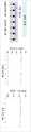
도 1 은 분류 효과를 설명하기 위한 개념도,1 is a conceptual diagram for explaining a classification effect;
이하, 도면을 참조하여 본 발명의 용접팁의 단면적 조절을 통한 멀티 레이어 용접이 가능한 용접방법 및 이를 이용한 용접장치의 구성을 상세하게 설명한다.Hereinafter, the configuration of a welding method capable of multi-layer welding by adjusting the cross-sectional area of a welding tip and a welding device using the same will be described in detail with reference to the drawings.
단, 개시된 도면들은 당업자에게 본 발명의 사상이 충분하게 전달될 수 있도록 하기 위한 예로서 제공되는 것이다. 따라서, 본 발명은 이하 제시되는 도면들에 한정되지 않고 다른 태양으로 구체화될 수도 있다.However, the disclosed drawings are provided as examples to sufficiently convey the spirit of the present invention to those skilled in the art. Accordingly, the present invention may be embodied in other aspects without being limited to the drawings presented below.
또한, 본 발명 명세서에서 사용되는 용어에 있어서 다른 정의가 없다면, 본발명이 속하는 기술 분야에서 통상의 지식을 가진 자가 통상적으로 이해하고 있는의미를 가지며, 하기의 설명 및 첨부 도면에서 본 발명의 요지를 불필요하게 흐릴 수 있는 공지 기능 및 구성에 대한 상세한 설명은 생략한다.In addition, unless otherwise defined, the terms used in the specification of the present invention have meanings commonly understood by those of ordinary skill in the art to which the present invention belongs, and the subject matter of the present invention is described in the following description and accompanying drawings. Detailed descriptions of well-known functions and configurations that may be unnecessarily obscure are omitted.
본 발명은 기본적으로 멀티 레이어, 특히, 차량용 다중 강판의 스팟 용접이 가능한 용접방법 및 이를 이용한 용접장치를 제공하고자 창안된 것이다.The present invention is basically conceived to provide a welding method capable of spot welding multi-layer, in particular, multi-vehicle steel plates, and a welding apparatus using the same.
기존 IIHS 스몰오버랩 및 측면충돌 시험시 실사이드부 용접점 계면파단(너겟경미달) 및 버튼파단으로 차체 변형량 증가로 충돌 성능 미달이 발생되는 문제가 있어 왔는데, 이로 인하여, 용접점 및 구조용 접착제를 추가하여 재시험을 실시하는 사례가 다수 발생되어 왔다. 또한, 재시험 차량에 대해 사전확인 및 시험 비용에 고가의 비용이 소요되므로 이에 대한 개선책이 필요하다.In the existing IIHS small overlap and side impact tests, there has been a problem of insufficient crash performance due to an increase in body deformation due to interfacial fracture (under-nugget) and button fracture at the sill side welding point. There have been many cases of retesting. In addition, since the cost of pre-checking and testing of the retest vehicle is expensive, improvement measures are required.
통상적으로, 충돌성능을 개선하기 위해서는 용접피치 간격을 줄여서 많은 용접점을 확보해야 하지만, 분류 효과(Shunt effect)에 의해 용접점 수를 확대하기가 어렵다.In general, in order to improve collision performance, it is necessary to secure a large number of welding points by reducing the welding pitch interval, but it is difficult to increase the number of welding points due to the shunt effect.
도 1 은 분류 효과를 설명하기 위한 개념도로서, 도시된 바와 같이, 용접부와 관계가 없는 곳으로 용접전류가 흐르게 되는 분류 효과(Shunt effect)가 발생할 경우, 실제 용접부로 전해지는 전류 감소로 인해 용접에 사용되는 발열량이 감소하여 용접강도가 저하되게 된다.1 is a conceptual diagram for explaining the shunting effect. As shown, when a shunt effect in which a welding current flows to a place unrelated to a welding part occurs, the current transmitted to the actual welding part is reduced, resulting in welding. As the amount of heat used is reduced, the welding strength is lowered.
이에 대한 해결책으로 구매 가능한 다양한 용접기를 이용하여 분류 효과에 의해 손실된 전류 및 열량을 보충해 줄 수 있으나, 이는 통상 2겹 용접만 가능한 것이어서, 통상의 충돌부재가 대부분 3겹 이상 용접이라는 측면에서 공지의 용접기로는 근본적인 해결방안을 제공할 수 없다.As a solution to this, it is possible to compensate for the current and heat lost by the shunting effect using various commercially available welding machines, but this is usually only possible for two-ply welding, so most of the common collision members are welded with three or more layers. welding machine cannot provide a fundamental solution.
따라서, 종래에는 분류효과에 의한 저항 패턴에 따라 전류 및 열량을 보충하는 방식을 채용하고 있는 용접기를 이용하였다.Therefore, in the prior art, a welding machine employing a method of supplementing current and heat amount according to a resistance pattern due to a shunting effect was used.
구체적으로, 종래의 용접기는 숏피치(30mm) 용접시 2겹 용접 적용이 가능하나, 3겹 이상 용접시에는 계면간 접촉저항 차이에 의해 적용이 불가능하며, 이러한 문제점은 특히 30mm 미만, 특히 10mm 수준의 숏피치에서는 더욱 문제가 커진다.Specifically, conventional welders can apply 2-ply welding when welding short pitch (30mm), but when welding 3 or more layers, it is impossible to apply due to the difference in contact resistance between interfaces. This problem is particularly less than 30mm, especially 10mm level In the case of short pitches, the problem becomes even greater.
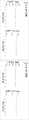
이러한 종래의 용접기의 열량 손실 보상과 한계는 도 2 및 도 3 의 그래프를 통하여 확인할 수 있다.Compensation for heat loss and limitations of the conventional welding machine can be confirmed through the graphs of FIGS. 2 and 3 .
도 2 는 종래 용접기를 2겹 숏피치(10mm 피치 적용) 용접 적용시의 그래프로서, 분류효과에 의한 열량 손실을 용접기가 보상하고 있는 것을 나타낸다.2 is a graph when a conventional welding machine is applied to 2-ply short pitch (applying 10 mm pitch) welding, and shows that the welding machine compensates for the heat loss due to the jetting effect.
또한, 도 3 은 종래 용접기를 3겹 숏피치(10mm 피치 적용) 용접 적용시의 그래프로서, 분류 효과에 의해 강도 저하 및 너겟경 크기가 미달됨을 나타내고 있다.In addition, FIG. 3 is a graph when a conventional welding machine is applied to 3-ply short pitch (10 mm pitch applied) welding, showing that the strength is lowered and the size of the nugget diameter is not reached due to the classification effect.
이처럼 종래의 용접기가 3겹 용접에서 전류 보상이 이루어지지 않는 이유는 계면저항 차이에 의한 너겟경 형성 시간차가 발생하나 동일하게 전류보상이 이루어지지 못하고, 접합면에 따라 불균일한 보상이 이루어지게 되어, 3겹 용접 적용이 불가능한 것으로 판명되었다.The reason why the current compensation is not performed in the three-layer welding of the conventional welder is that the time difference in forming the nugget diameter occurs due to the difference in interface resistance, but the same current compensation is not performed, and uneven compensation is made depending on the joint surface, A three-ply weld application proved impossible.
도 4 및 도 5 는 종래 용접기의 2겹 용접 적용시 및 3겹 용접 적용시의 분류효과의 보상을 나타내고 있다.4 and 5 show the compensation of the classification effect when applying 2-ply welding and 3-ply welding of the conventional welding machine.
즉, 도 4 에 도시된 바와 같이, 종래 용접기의 2겹 용접 적용시 분류효과에 의한 전류 손실을 지용접기가 보상하도록 용접조건을 설정할 수 있으나, 도 5 에도시된 바와 같이, 종래 용접기의 3겹 용접 적용시에는 너겟경 형성에 시간차가 발생되며, 특히, 보상전류를 초고장력강에서 더 많이 소모하게 되어 불균일한 보상이 더 크게 발생됨을 보여주고 있다.That is, as shown in FIG. 4, welding conditions can be set so that the ground welding machine compensates for the current loss due to the shunting effect when two-ply welding is applied by the conventional welding machine, but in FIG.As shown, when applying 3-ply welding of a conventional welder, a time difference occurs in forming a nugget diameter, and in particular, more compensation current is consumed in ultra-high-strength steel, resulting in greater non-uniform compensation.
본 발명은 이러한 문제점을 해소하기 위하여, 패널형 용접대상체의 마주보는 양 외측면에 배열된 두 용접팁의 단면적 조절을 통해서 멀티 레이어, 특히, 다겹 용접시 계면들 사이의 발열량이 유사하도록 제어하여 너겟경이 동시에 형성되어 접합면 사이에 균일하게 열량 보상이 가능도록 하는 방안을 구상하였다.In order to solve this problem, the present invention controls the calorific value between the interfaces during multi-layer, in particular, multi-layer welding to be similar through the adjustment of the cross-sectional area of the two welding tips arranged on both outer surfaces of the panel-type welding object facing each other, so that the nugget A plan was conceived to enable thermal compensation to be uniformly formed between the bonding surfaces by forming the mirror at the same time.
여기서, 용접시의 발열량은 하기의 수학식 1 과 같이 강판의 저항에 비례한다.Here, the calorific value during welding is proportional to the resistance of the steel sheet as shown in
(수학식 1)(Equation 1)

또한, 도 6 의 3겹 용접의 개념도를 참조하면, 3겹 용접시 용접팁 단면적에 따른 계면사이의 비저항은 아래와 같이 계산될 수 있다.In addition, referring to the conceptual diagram of 3-ply welding in FIG. 6, the resistivity between interfaces according to the cross-sectional area of the welding tip during 3-ply welding can be calculated as follows.
도 6 을 참조하면, 단면적 A 의 지름은
단면적 B의 지름은

또한, 단면적 A와 단면적 B에서 발열량이 같기 위해서는 아래 수학식 2 를 만족해야 한다.In addition, in order to have the same calorific value in the cross-sectional area A and the cross-sectional area B,
(수학식 2)(Equation 2)

여기서, 상기 수학식 2 의 양변을 정리하면,Here, summarizing both sides of

이고, 멀티 레이어로 중첩된 패널형 용접대상체의 마주보는 양 외측면에 배열된 두 용접팁의 단면적의 관계식에서 두 용접팁의 단면적 비율(x/y)은 용접대상체의 두께와 비저항의 함수인 수학식 3 으로 정리된다., and in the relational expression of the cross-sectional areas of the two welding tips arranged on the opposite outer surfaces of the multi-layered panel-type welding object, the cross-sectional area ratio (x / y ) of the two welding tips is a function of the thickness and specific resistance of the welding object Math It is summarized as
(수학식 3)(Equation 3)

수학식 3 에서 ρ는 용접대상체 각 층의 비저항이고,t는 용접대상체 각 층의 두께이고, 본 발명이 멀티 레이어로 중첩된 패널형 용접대상체에 대한 것이기에,i 는 용접대상체의 수로 2이상의 자연수이다.In
나아가, 패널형 용접대상체, 특히, 강판의 비저항은 탄소당량에 비례하여 도 7 에 도시된 비저항-강도(K급) 비례 그래프에 도시된 바와 같은 특성을 가진다.Furthermore, the resistivity of the panel-type welded object, in particular, the steel sheet, is proportional to the carbon equivalent and has characteristics as shown in the resistivity-strength (K class) proportional graph shown in FIG.
도 7 의 그래프와 같이, 80K 급 강도 강판부터 비저항이 급상승하고, 저발열 그룹은 연강~60K 급 강판이며, 고발열 그룹은 80K급 이상 강판(핫스탬핑 포함)이고, 결국, 발열량은 비저항에 비례하며, 비저항은 소재 탄소당량에 비례함을 이용할 수 있다.As shown in the graph of FIG. 7, the specific resistance rises rapidly from the 80K class strength steel sheet, the low heating group is mild steel to 60K class steel sheet, and the high heating group is 80K class or higher steel sheet (including hot stamping). Eventually, the calorific value is proportional to the specific resistance, , it can be used that the resistivity is proportional to the carbon equivalent of the material.
한편, 도 7 에서
그러므로, 두 용접팁 크기의 비율은 상술한 수학식 3 으로 인해 결정되는 바, 용접팁 크기의 비율은 강판의 두께와 비저항의 함수로 나타낼 수 있고, 강판은 강도에 따라 비저항이 증가하게 된다.Therefore, the ratio of the two welding tip sizes is determined by
이때, 범용적으로 사용되는 강판의 비저항의 평균값은 위 그래프와 같다.At this time, the average value of the specific resistance of the steel sheet used universally is as shown in the graph above.
나아가, 강판의 비저항의 산포를 고려하여 수학식 3 의 비율에 ±20%, 바람직하기로는, 아래의 수학식 4 와 같이 ±10% 의 허용치를 갖는다.Furthermore, in consideration of the dispersion of the resistivity of the steel sheet, the ratio of
(수학식 4)(Equation 4)

통상적으로, 분류효과는 용접점 사이의 간격이 30mm 보다 작아지면 발생하여 피치간격이 작을수록 심해지고, 용접팁과 너겟경의 크기로 인한 숏피치 용접의 한계는 약 10mm 정도이다.In general, the classification effect occurs when the distance between welding points is smaller than 30 mm, and the smaller the pitch distance, the more severe, and the limit of short pitch welding due to the size of the welding tip and the nugget diameter is about 10 mm.
본 발명은 멀티 레이어로 중첩된 패널형 용접대상체, 특히 3겹 이상의 강판에 대하여 10~30mm간격의 숏피치 용접에 적용시 분류효과와 무관한 균일한 용접품질(인장강도, 너겟경 크기)이 확보가 가능하다.The present invention secures uniform welding quality (tensile strength, nugget diameter size) independent of the classification effect when applied to short pitch welding at intervals of 10 to 30 mm for multi-layered panel-type welding objects, especially three or more layers of steel plates is possible
또한, 도 8 의 소재 강도에 따른 비저항 산포의 그래프를 참조하면, 패널형 용접대상체, 즉 강판의 강도가 높아질수록 비저항 산포가 증가함을 알 수 있다.In addition, referring to the graph of the resistivity distribution according to the material strength of FIG. 8, it can be seen that the resistivity distribution increases as the strength of the panel-type welding object, that is, the steel sheet increases.
도 9 는 종래 다양한 용접팁의 사진도면으로서, 본 발명은 이러한 용접팁의 단면적 조절을 통한 멀티 레이어 용접이 가능한 용접방법을 제공하며, 특히, 멀티 레이어로 중첩된 패널형 용접대상체의 마주보는 양 외측면에 배열된 두 용접팁의 단면적을 조절하여 용접대상체의 계면 사이의 발열량이 유사하도록 제어하여 너겟경이 동시에 형성되도록 한다.Figure 9 is a photographic view of various conventional welding tips, the present invention provides a welding method capable of multi-layer welding through adjusting the cross-sectional area of these welding tips, in particular, the facing sides of the panel-type welding object overlapped in multi-layers By adjusting the cross-sectional area of the two welding tips arranged on the side, the calorific value between the interface of the object to be welded is similar, so that the nugget diameter is formed at the same time.
또한, 본 발명의 용접방법은 두 용접팁의 단면적 비율(x/y)이 용접대상체의 두께와 비저항의 함수인 상기 수학식 3 을 만족하며, 이 용접팁의 단면적 비율(x/y)은 ±20% 의 허용치를 가지는 것이 바람직하다.In addition, in the welding method of the present invention, the cross-sectional area ratio (x/y ) of the two welding tips satisfies
나아가, 본 발명의 용접방법은 상기 용접팁의 단면적 비율(x/y)이 ±10% 의 허용치를 가지는 것이 보다 바람직하다.Furthermore, in the welding method of the present invention, it is more preferable that the cross-sectional area ratio (x/y ) of the welding tip has a tolerance of ±10%.
아울러, 본 발명의 용접방법은 용접스팟 사이인 간격인 피치 10~30mm (10이상mm, 30mm 미만)인 숏피치인 것이 바람직하다.In addition, the welding method of the present invention is preferably a short pitch that is a pitch of 10 to 30 mm (10 or more mm, less than 30 mm), which is an interval between welding spots.
또한, 상기 용접대상체의 수는 2 이상, 바람직하기로는 2~5, 보다 바람직하기로는 3 이상, 가장 바람직하기로는 3~5 이다.In addition, the number of the objects to be welded is 2 or more, preferably 2 to 5, more preferably 3 or more, and most preferably 3 to 5.
또한, 본 발명에 따른 용접장치는 상기 용접방법을 적용하여 이루어진다.In addition, the welding device according to the present invention is made by applying the above welding method.
상기와 같은 본 발명은 아래 실시예를 통하여 보다 잘 이해될 수 있다.The present invention as described above can be better understood through the following examples.
[실시예 1: 28K(8mm)-150K(12mm)-100K(10mm) 3겹 용접, 용접스팟의 피치간격 10mm][Example 1: 28K (8mm)-150K (12mm)-100K (10mm) 3-ply welding, welding spot pitch interval 10mm]
이때, 실시예 1 에서 적정 용접팁의 단면적 비율(x/y) 범위는
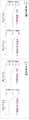
도 10a 내지 도 10c 는 실시예 1 의 용접팁 비율에 따른 인장강도 및 너겟경 크기를 나타내는 그래프로서, 도 10a 의 그래프를 참조하면, 용접팁의 비율이 적정 용접팁 비율 범위일 경우에는 편차 5% 내에 균일한 용접 품질을 확보할 수 있었다.10A to 10C are graphs showing tensile strength and nugget diameter size according to the welding tip ratio in Example 1. Referring to the graph of FIG. 10A, when the welding tip ratio is within the proper welding tip ratio range, the deviation is 5%. It was possible to secure uniform welding quality within
그러나, 도 10b 의 그래프를 참조하면, 용접팁의 비율이 적정 용접팁 비율보다 작을 때에는 인장강도가 저하되고 너겟경의 크기가 미달되었다.However, referring to the graph of FIG. 10B, when the welding tip ratio is smaller than the proper welding tip ratio, the tensile strength is lowered and the nugget diameter is less than the size.
또한, 도 10c 의 그래프를 참조하면, 용접팁의 비율 적정 용접팁 비율 범위보다 클 경우에는 인장강도가 저하되고 너겟경의 크기가 미달되었다.In addition, referring to the graph of FIG. 10C, when the welding tip ratio is greater than the proper welding tip ratio range, the tensile strength is lowered and the nugget diameter is less than the size.
상기와 같은 실시예 1 에서 이처럼 용접팁의 단면적 비율(x/y)이 적정 비율 범위보다 작거나 클 때 강도 저하 및 너겟경 크기 미달이 발생하는 이유는, 도 5 를 참조하여 설명한 바와 같이, 본 발명의 비대칭 용접방법 및 이를 이용한 용접장치의 목적이 용접팁의 크기 조절을 통해 다겹 용접시 계면들 사이의 발열량이 유사하도록 제어하여 접합면(A, B) 사이에 균일하게 열량 보상이 가능하도록 하는 것인바, 용접팁의 단면적 비율(x/y) 범위가 클 경우는 접합면 A에 충분한 발열량이 발생하지 못하고, 그 비율 범위가 작을 경우에는 오히려 접합면 A가 접합면 B에 비해 더 많은 발열량이 발생하게 되어 접합면 사이의 발열량이 불균일하게 되기 때문이다.In Example 1 as described above, when the cross-sectional area ratio (x/y ) of the welding tip is smaller or larger than the appropriate ratio range, the reason why the strength is lowered and the size of the nugget diameter is insufficient is as described with reference to FIG. 5, according to the present invention. The purpose of the asymmetric welding method and the welding device using the same is to control the calorific value between the interfaces during multi-layer welding by adjusting the size of the welding tip so that the heat amount can be compensated uniformly between the joint surfaces A and B. Invar, when the cross-sectional area ratio (x/y ) range of the welding tip is large, sufficient heat generation is not generated at the joint surface A, and when the range of the ratio is small, the joint surface A generates more heat than the joint surface B. This is because the amount of heat generated between the bonding surfaces becomes non-uniform.
이처럼 본 발명에 따른 용접팁의 단면적 조절을 통한 멀티 레이어 용접이 가능한 지능형 용접방법, 즉 비대칭 용접팁을 사용했을 경우 3겹 용접 및 10mm 숏피치 용접의 경우 인장강도와 너겟경 사이즈가 5% 안에 균일한 값을 갖는 것을 확인할 수 있었다.As such, an intelligent welding method capable of multi-layer welding by adjusting the cross-sectional area of the welding tip according to the present invention, that is, when using an asymmetric welding tip, the tensile strength and nugget diameter size are uniform within 5% in the case of 3-layer welding and 10 mm short pitch welding It was found to have a single value.
특히, 강판의 품질 산포를 고려하고 상기 수학식 3 에 기반한 비대칭 용접팁을 사용할 경우 가장 가혹한 10mm 의 숏피치 용접에서도 균일하고 강건한 용접 품질을 확보할 수 있음을 확인하였다.In particular, it was confirmed that uniform and robust welding quality can be secured even in the harshest 10 mm short pitch welding when the asymmetric welding tip is used considering the quality distribution of the steel plate and based on
[실시예 2: 용접대상체의 수가 3인(A,B,C) 3겹 중첩 패널형 용접대상체, 특히, 강판의 두께 비율 및 강도에 따른 용접팁의 단면적 비율(x/y) 범위][Example 2: 3-layer overlapping panel-type welding object having three (A, B, C) welding objects, in particular, the cross-sectional area ratio (x / y ) range of the welding tip according to the thickness ratio and strength of the steel plate]
상기 실시예 2 는 용접대상체의 수가 3인(A,B,C) 3겹 중첩 패널형 용접대상체, 특히, 강판의 두께 비율 및 강도에 따라서 편차 5% 내의 균일한 용접 품질을 확보할 수 있는 용접팁의 적정 단면적 비율(x/y) 범위를 측정하여 표 1 내지 표 4 로 나타내었다.Example 2 is a three-layer overlapping panel type welding object having three (A, B, C) welding objects, in particular, welding that can secure uniform welding quality within 5% of the deviation according to the thickness ratio and strength of the steel plate The proper cross-sectional area ratio (x/y ) range of the tip was measured and shown in Tables 1 to 4.
(표 1)(Table 1)

(표 2)(Table 2)

(표 3)(Table 3)

* 표 3 의 28K(8mm)-150K(12mm)-100K(10mm)의 용접팁 비율은 상술한 실시예 1 의 범위이다.* The welding tip ratios of 28K (8mm) - 150K (12mm) - 100K (10mm) in Table 3 are in the range of Example 1 described above.
(표 4)(Table 4)

Claims (6)
Translated fromKoreanMulti-layer welding capable of simultaneous formation of nugget diameters by controlling the cross-sectional area of two welding tips arranged on opposite outer surfaces of multi-layered panel-type welding objects overlapped so that the calorific value between the interfaces of the welding objects is similar. Way.
상기 두 용접팁의 단면적 비율(x/y)은 용접대상체의 두께와 비저항의 함수인 다음 식을 만족하며, 이 용접팁의 단면적 비율(x/y)은 ±10% 의 허용치를 갖는 것을 특징으로 하는 멀티 레이어 용접이 가능한 용접방법:

(여기서, ρ는 용접대상체 각 층의 비저항,t는 용접대상체 각 층의 두께,i 는 용접대상체의 수로 2이상의 자연수임).
According to claim 1,
The cross-sectional area ratio (x/y ) of the two welding tips satisfies the following equation, which is a function of the thickness and specific resistance of the welding object, and the cross-sectional area ratio (x/y ) of the welding tip has a tolerance of ±10%. Welding methods that allow multi-layer welding to:
(Where, ρ is the resistivity of each layer of the object to be welded,t is the thickness of each layer of the object to be welded,i is the number of objects to be welded and is a natural number of 2 or more).
상기 용접팁의 단면적 비율(x/y)은 ±20% 의 허용치를 갖는 것을 특징으로 하는 멀티 레이어 용접이 가능한 용접방법.According to claim 2,
The cross-sectional area ratio (x / y ) of the welding tip is a welding method capable of multi-layer welding, characterized in that it has a tolerance of ± 20%.
용접스팟 사이인 간격인 피치는 10~30mm인 숏피치인 것을 특징으로 하는 멀티 레이어 용접이 가능한 용접방법.
According to claim 2,
A welding method capable of multi-layer welding, characterized in that the pitch between the welding spots is a short pitch of 10 to 30 mm.
상기 용접대상체의 수는 3 이상인 것을 특징으로 하는 멀티 레이어 용접이 가능한 용접방법.
According to claim 2,
A welding method capable of multi-layer welding, characterized in that the number of the welding target object is 3 or more.
Priority Applications (2)
| Application Number | Priority Date | Filing Date | Title |
|---|---|---|---|
| KR1020210091261AKR20230010561A (en) | 2021-07-12 | 2021-07-12 | Spot welding method for multi-layers and spot welding apparatus using the same |
| US17/532,897US20230049894A1 (en) | 2021-07-12 | 2021-11-22 | Spot welding method for multi-layers and spot welding apparatus using the same |
Applications Claiming Priority (1)
| Application Number | Priority Date | Filing Date | Title |
|---|---|---|---|
| KR1020210091261AKR20230010561A (en) | 2021-07-12 | 2021-07-12 | Spot welding method for multi-layers and spot welding apparatus using the same |
Publications (1)
| Publication Number | Publication Date |
|---|---|
| KR20230010561Atrue KR20230010561A (en) | 2023-01-19 |
Family
ID=85078032
Family Applications (1)
| Application Number | Title | Priority Date | Filing Date |
|---|---|---|---|
| KR1020210091261APendingKR20230010561A (en) | 2021-07-12 | 2021-07-12 | Spot welding method for multi-layers and spot welding apparatus using the same |
Country Status (2)
| Country | Link |
|---|---|
| US (1) | US20230049894A1 (en) |
| KR (1) | KR20230010561A (en) |
Family Cites Families (17)
| Publication number | Priority date | Publication date | Assignee | Title |
|---|---|---|---|---|
| JP5014834B2 (en)* | 2007-02-27 | 2012-08-29 | 住友軽金属工業株式会社 | MIG welding method for aluminum and steel |
| US8058584B2 (en)* | 2007-03-30 | 2011-11-15 | Nissan Motor Co., Ltd. | Bonding method of dissimilar materials made from metals and bonding structure thereof |
| JP4494496B2 (en)* | 2008-06-06 | 2010-06-30 | 本田技研工業株式会社 | Resistance welding method and welded structure |
| KR20100023488A (en)* | 2008-08-22 | 2010-03-04 | 현대자동차주식회사 | Welding method for aluminum sheets |
| JP5427074B2 (en)* | 2009-03-31 | 2014-02-26 | 本田技研工業株式会社 | Resistance welding method and apparatus |
| JP5468350B2 (en)* | 2009-10-23 | 2014-04-09 | マツダ株式会社 | Dissimilar metal plate joining method |
| US8357870B1 (en)* | 2010-03-22 | 2013-01-22 | Honda Motor Co., Ltd. | Intelligent stepper welding system and method |
| US8541110B2 (en)* | 2011-01-19 | 2013-09-24 | GM Global Technology Operations LLC | Resistance spot welding manufacture and method of forming same |
| JP5498463B2 (en)* | 2011-10-13 | 2014-05-21 | 富士重工業株式会社 | Pressure control method for spot welding equipment |
| WO2014045431A1 (en)* | 2012-09-24 | 2014-03-27 | 新日鐵住金株式会社 | Spot welding method for high-strength steel sheet excellent in joint strength |
| CA2917122C (en)* | 2013-07-31 | 2018-02-20 | Nippon Steel & Sumitomo Metal Corporation | Arc spot welded joint and manufacturing method thereof |
| WO2015037652A1 (en)* | 2013-09-12 | 2015-03-19 | 新日鐵住金株式会社 | Resistance spot welding method and welded structure |
| JP6360056B2 (en)* | 2014-03-05 | 2018-07-18 | Jfeスチール株式会社 | Resistance spot welding method |
| US10279418B2 (en)* | 2014-07-16 | 2019-05-07 | Honda Motor Co., Ltd. | Method and apparatus for resistive spot welding |
| CN107000109B (en)* | 2014-12-01 | 2021-09-10 | 杰富意钢铁株式会社 | Resistance spot welding method |
| JP5999293B1 (en)* | 2015-03-16 | 2016-09-28 | Jfeスチール株式会社 | Resistance spot welding method and resistance spot welding joint manufacturing method |
| JP6984469B2 (en)* | 2018-02-09 | 2021-12-22 | トヨタ自動車株式会社 | How to join dissimilar metal plates |
- 2021
- 2021-07-12KRKR1020210091261Apatent/KR20230010561A/enactivePending
- 2021-11-22USUS17/532,897patent/US20230049894A1/enactivePending
Also Published As
| Publication number | Publication date |
|---|---|
| US20230049894A1 (en) | 2023-02-16 |
Similar Documents
| Publication | Publication Date | Title |
|---|---|---|
| CN102602072B (en) | Resistance spot welding manufacture and method of forming same | |
| JP5267320B2 (en) | Steel plate lap welding method and steel plate lap weld joint | |
| JP5999293B1 (en) | Resistance spot welding method and resistance spot welding joint manufacturing method | |
| CN102059439B (en) | Joining method of dissimilar metal plates | |
| US20090302010A1 (en) | Resistance welding method and welded structure | |
| KR100443803B1 (en) | Method for the projection welding of high-carbon steels and high-tension low-alloy | |
| RU2676542C2 (en) | Arc point welding method and welding machine for its implementation | |
| CN107000109A (en) | Resistance spot welding method | |
| CN104125872A (en) | Method for seam welding of end flange connections | |
| KR102127991B1 (en) | Resistance spot welding method and welded structure | |
| JP2009241112A (en) | Resistance spot welding method | |
| JPWO2019160141A1 (en) | Resistance spot welding method and method for manufacturing welded member | |
| US9868175B2 (en) | Seam welding method and seam welding device | |
| US6545244B1 (en) | Conductive heat seam welding | |
| JP6658992B1 (en) | Resistance spot welding method and method for manufacturing welded member | |
| JP2021003733A (en) | Resistance spot welding method and manufacturing method for welding member | |
| JP6094079B2 (en) | Resistance spot welding method | |
| JP2012187616A (en) | Resistance welding apparatus and resistance welding method | |
| KR20230010561A (en) | Spot welding method for multi-layers and spot welding apparatus using the same | |
| US20040256366A1 (en) | Welding device of fuel tank for vehicle and welding method thereof | |
| CN105269140B (en) | The method for connecting two components | |
| JPWO2020004117A1 (en) | Resistance spot welding method and welding member manufacturing method | |
| CN114473164B (en) | Method for resistance spot welding dissimilar metal workpiece stacked assembly and dissimilar metal stacked assembly for resistance spot welding | |
| JP6658993B1 (en) | Resistance spot welding method and method for manufacturing welded member | |
| Kügler et al. | Inductive preheating in laser beam welding of multimaterial joints of 22MnB5 and AA6016 |
Legal Events
| Date | Code | Title | Description |
|---|---|---|---|
| PA0109 | Patent application | St.27 status event code:A-0-1-A10-A12-nap-PA0109 | |
| PG1501 | Laying open of application | St.27 status event code:A-1-1-Q10-Q12-nap-PG1501 | |
| A201 | Request for examination | ||
| PA0201 | Request for examination | St.27 status event code:A-1-2-D10-D11-exm-PA0201 | |
| PE0902 | Notice of grounds for rejection | St.27 status event code:A-1-2-D10-D21-exm-PE0902 |