KR20230007678A - MEMS microphone - Google Patents
MEMS microphoneDownload PDFInfo
- Publication number
- KR20230007678A KR20230007678AKR1020210088307AKR20210088307AKR20230007678AKR 20230007678 AKR20230007678 AKR 20230007678AKR 1020210088307 AKR1020210088307 AKR 1020210088307AKR 20210088307 AKR20210088307 AKR 20210088307AKR 20230007678 AKR20230007678 AKR 20230007678A
- Authority
- KR
- South Korea
- Prior art keywords
- diaphragm
- counter electrode
- counter
- mems microphone
- counter electrodes
- Prior art date
- Legal status (The legal status is an assumption and is not a legal conclusion. Google has not performed a legal analysis and makes no representation as to the accuracy of the status listed.)
- Withdrawn
Links
Images


Classifications
- H—ELECTRICITY
- H04—ELECTRIC COMMUNICATION TECHNIQUE
- H04R—LOUDSPEAKERS, MICROPHONES, GRAMOPHONE PICK-UPS OR LIKE ACOUSTIC ELECTROMECHANICAL TRANSDUCERS; DEAF-AID SETS; PUBLIC ADDRESS SYSTEMS
- H04R19/00—Electrostatic transducers
- H04R19/04—Microphones
- B—PERFORMING OPERATIONS; TRANSPORTING
- B81—MICROSTRUCTURAL TECHNOLOGY
- B81B—MICROSTRUCTURAL DEVICES OR SYSTEMS, e.g. MICROMECHANICAL DEVICES
- B81B3/00—Devices comprising flexible or deformable elements, e.g. comprising elastic tongues or membranes
- B81B3/0064—Constitution or structural means for improving or controlling the physical properties of a device
- B81B3/0094—Constitution or structural means for improving or controlling physical properties not provided for in B81B3/0067 - B81B3/0091
- H—ELECTRICITY
- H04—ELECTRIC COMMUNICATION TECHNIQUE
- H04R—LOUDSPEAKERS, MICROPHONES, GRAMOPHONE PICK-UPS OR LIKE ACOUSTIC ELECTROMECHANICAL TRANSDUCERS; DEAF-AID SETS; PUBLIC ADDRESS SYSTEMS
- H04R1/00—Details of transducers, loudspeakers or microphones
- H04R1/08—Mouthpieces; Microphones; Attachments therefor
- H—ELECTRICITY
- H04—ELECTRIC COMMUNICATION TECHNIQUE
- H04R—LOUDSPEAKERS, MICROPHONES, GRAMOPHONE PICK-UPS OR LIKE ACOUSTIC ELECTROMECHANICAL TRANSDUCERS; DEAF-AID SETS; PUBLIC ADDRESS SYSTEMS
- H04R19/00—Electrostatic transducers
- H04R19/005—Electrostatic transducers using semiconductor materials
- H—ELECTRICITY
- H04—ELECTRIC COMMUNICATION TECHNIQUE
- H04R—LOUDSPEAKERS, MICROPHONES, GRAMOPHONE PICK-UPS OR LIKE ACOUSTIC ELECTROMECHANICAL TRANSDUCERS; DEAF-AID SETS; PUBLIC ADDRESS SYSTEMS
- H04R31/00—Apparatus or processes specially adapted for the manufacture of transducers or diaphragms therefor
- H04R31/003—Apparatus or processes specially adapted for the manufacture of transducers or diaphragms therefor for diaphragms or their outer suspension
- H—ELECTRICITY
- H04—ELECTRIC COMMUNICATION TECHNIQUE
- H04R—LOUDSPEAKERS, MICROPHONES, GRAMOPHONE PICK-UPS OR LIKE ACOUSTIC ELECTROMECHANICAL TRANSDUCERS; DEAF-AID SETS; PUBLIC ADDRESS SYSTEMS
- H04R7/00—Diaphragms for electromechanical transducers; Cones
- H04R7/02—Diaphragms for electromechanical transducers; Cones characterised by the construction
- H04R7/04—Plane diaphragms
- H—ELECTRICITY
- H04—ELECTRIC COMMUNICATION TECHNIQUE
- H04R—LOUDSPEAKERS, MICROPHONES, GRAMOPHONE PICK-UPS OR LIKE ACOUSTIC ELECTROMECHANICAL TRANSDUCERS; DEAF-AID SETS; PUBLIC ADDRESS SYSTEMS
- H04R1/00—Details of transducers, loudspeakers or microphones
- H04R1/20—Arrangements for obtaining desired frequency or directional characteristics
- H04R1/32—Arrangements for obtaining desired frequency or directional characteristics for obtaining desired directional characteristic only
- H04R1/34—Arrangements for obtaining desired frequency or directional characteristics for obtaining desired directional characteristic only by using a single transducer with sound reflecting, diffracting, directing or guiding means
- H04R1/38—Arrangements for obtaining desired frequency or directional characteristics for obtaining desired directional characteristic only by using a single transducer with sound reflecting, diffracting, directing or guiding means in which sound waves act upon both sides of a diaphragm and incorporating acoustic phase-shifting means, e.g. pressure-gradient microphone
- H—ELECTRICITY
- H04—ELECTRIC COMMUNICATION TECHNIQUE
- H04R—LOUDSPEAKERS, MICROPHONES, GRAMOPHONE PICK-UPS OR LIKE ACOUSTIC ELECTROMECHANICAL TRANSDUCERS; DEAF-AID SETS; PUBLIC ADDRESS SYSTEMS
- H04R2201/00—Details of transducers, loudspeakers or microphones covered by H04R1/00 but not provided for in any of its subgroups
- H04R2201/003—Mems transducers or their use
- H—ELECTRICITY
- H04—ELECTRIC COMMUNICATION TECHNIQUE
- H04R—LOUDSPEAKERS, MICROPHONES, GRAMOPHONE PICK-UPS OR LIKE ACOUSTIC ELECTROMECHANICAL TRANSDUCERS; DEAF-AID SETS; PUBLIC ADDRESS SYSTEMS
- H04R2410/00—Microphones
- H04R2410/03—Reduction of intrinsic noise in microphones
- H—ELECTRICITY
- H04—ELECTRIC COMMUNICATION TECHNIQUE
- H04R—LOUDSPEAKERS, MICROPHONES, GRAMOPHONE PICK-UPS OR LIKE ACOUSTIC ELECTROMECHANICAL TRANSDUCERS; DEAF-AID SETS; PUBLIC ADDRESS SYSTEMS
- H04R7/00—Diaphragms for electromechanical transducers; Cones
- H04R7/16—Mounting or tensioning of diaphragms or cones
- H04R7/18—Mounting or tensioning of diaphragms or cones at the periphery
- H04R7/20—Securing diaphragm or cone resiliently to support by flexible material, springs, cords, or strands
Landscapes
- Engineering & Computer Science (AREA)
- Physics & Mathematics (AREA)
- Acoustics & Sound (AREA)
- Signal Processing (AREA)
- Multimedia (AREA)
- Manufacturing & Machinery (AREA)
- Computer Hardware Design (AREA)
- Microelectronics & Electronic Packaging (AREA)
- Electrostatic, Electromagnetic, Magneto- Strictive, And Variable-Resistance Transducers (AREA)
- Pressure Sensors (AREA)
- Micromachines (AREA)
Abstract
Description
Translated fromKorean본 발명의 실시예들은 멤스 마이크로폰에 관한 것으로, 보다 상세하게는, 음압을 감지하여 변위를 발생시킴으로써 음성 신호를 생성할 수 있는 멤스 마이크로폰에 관한 것이다.Embodiments of the present invention relate to a MEMS microphone, and more particularly, to a MEMS microphone capable of generating an audio signal by sensing sound pressure and generating a displacement.
일반적으로 콘덴서형 마이크로폰은 서로 마주하는 두 전극 사이에 형성된 정전용량을 이용하여 음성 신호를 출력한다. 상기 콘덴서형 마이크로폰은 반도체 멤스 공정을 통해 제조될 수 있다.In general, a condenser type microphone outputs a voice signal using capacitance formed between two electrodes facing each other. The condenser type microphone may be manufactured through a semiconductor MEMS process.
상기 멤스 공정을 통해 제조되는 멤스 마이크로폰은 캐비티가 형성된 기판과 벤딩 가능하게 구비되는 진동판 및 상기 진동판과 마주하게 구비되는 백 플레이트를 구비할 수 있다. 또한, 상기 마이크로폰은 상기 백 플레이트를 홀드하여 상기 진동판으로부터 이격시키는 상부 절연막을 갖는다. 상기 상부 절연막은 상기 진동판과 상기 백 플레이트 사이에 에어 갭을 형성하기 위한 절곡된 지지대를 갖는다.The MEMS microphone manufactured through the MEMS process may include a substrate on which a cavity is formed, a diaphragm that is bendable, and a back plate that faces the diaphragm. In addition, the microphone has an upper insulating film that holds the back plate and separates it from the diaphragm. The upper insulating film has a bent support for forming an air gap between the diaphragm and the back plate.
상기 지지대에서 응력이 집중되어 상기 상부 절연막의 처짐이 발생하고, 이로 인해 상기 백 플레이트가 처질 수 있다. 상기 백 플레이트의 처짐으로 인해 상기 에어 갭이 감소하므로, 상기 멤스 마이크로폰의 감도가 저하될 수 있다.Stress is concentrated in the support, causing sagging of the upper insulating layer, which may cause the back plate to sag. Since the air gap decreases due to the deflection of the back plate, the sensitivity of the MEMS microphone may decrease.
또한, 음압에 의해 상기 진동판과 상기 백 플레이트가 접착되는 것을 방지하기 위해 상기 백 플레이트에 딤플들을 형성하거나, 상기 진동판과 상기 백 플레이트에 소수성 물질을 도포해야 한다. 따라서, 상기 멤스 마이크로폰의 제조 비용이 증가할 수 있다.In addition, in order to prevent adhesion between the diaphragm and the back plate due to negative pressure, dimples may be formed on the back plate or a hydrophobic material may be applied to the diaphragm and the back plate. Accordingly, the manufacturing cost of the MEMS microphone may increase.
그리고, 상기 진동판과 상기 백 플레이트로 이루어지는 상기 멤스 마이크로폰은 상기 출력 신호가 단일 신호이므로, 상기 출력 신호가 전달되거나 처리되는 과정에서 잡음이 추가될 수 있다. 따라서 상기 멤스 마이크로폰의 성능이 저하될 수 있다.In addition, since the output signal of the MEMS microphone including the diaphragm and the back plate is a single signal, noise may be added while the output signal is transmitted or processed. Therefore, the performance of the MEMS microphone may be degraded.
본 발명의 실시예들은 진동판의 진동으로 인해 출력 신호를 복수 신호로 출력하는 멤스 마이크로폰을 제공한다.Embodiments of the present invention provide a MEMS microphone that outputs an output signal as a plurality of signals due to vibration of a diaphragm.
본 발명에 따른 멤스 마이크로폰은, 음압에 의해 상하로 진동하는 진동판 및 상기 진동판과 수평 방향으로 이격되도록 배치되며, 서로 절연되도록 상하로 적층되어 다층으로 이루어지며, 상기 진동판의 상하 변위에 따라 복수의 전기 신호들을 발생하는 상대 전극들을 포함할 수 있다.The MEMS microphone according to the present invention includes a diaphragm that vibrates up and down by sound pressure, and is arranged to be spaced apart from the diaphragm in a horizontal direction, and is stacked vertically to be insulated from each other. It may include counter electrodes that generate signals.
본 발명의 일 실시예들에 따르면, 상기 상대 전극들은 서로 다른 높이에 각각 위치하는 제1 상대 전극 및 제2 상대 전극을 포함하고, 상기 진동판은 상기 제1 상대 전극과 상기 제2 상대 전극의 사이의 높이에 위치할 수 있다.According to one embodiment of the present invention, the counter electrodes include a first counter electrode and a second counter electrode positioned at different heights, and the diaphragm is between the first counter electrode and the second counter electrode. can be located at the height of
본 발명의 일 실시예들에 따르면, 상기 상대 전극들은 서로 다른 높이에 각각 위치하는 제1 상대 전극 및 제2 상대 전극을 포함하고, 상기 진동판은 상기 제1 상대 전극과 상기 제2 상대 전극 중 어느 하나의 높이와 동일한 높이에 위치할 수 있다.According to one embodiment of the present invention, the counter electrodes include a first counter electrode and a second counter electrode respectively positioned at different heights, and the diaphragm is any one of the first counter electrode and the second counter electrode. It can be located at the same height as one height.
본 발명의 일 실시예들에 따르면, 상기 상대 전극들은 서로 다른 높이에 순차적으로 각각 위치하는 제1 상대 전극, 제2 상대 전극 및 제3 상대 전극을 포함하고, 상기 진동판은 상기 제2 상대 전극이 높이와 동일한 높이에 위치할 수 있다.According to one embodiment of the present invention, the counter electrodes include a first counter electrode, a second counter electrode, and a third counter electrode sequentially positioned at different heights, and the diaphragm includes the second counter electrode It may be located at the same height as the height.
본 발명의 일 실시예들에 따르면, 상기 진동판과 상기 상대 전극들의 대응 면적을 증가시키기 위해 상기 진동판은 복수의 제1 돌기들을 포함하고, 상기 상대 전극들은 상기 제1 돌기들과 맞물리는 제2 돌기들을 포함할 수 있다.According to one embodiment of the present invention, in order to increase the corresponding area of the diaphragm and the counter electrodes, the diaphragm includes a plurality of first protrusions, and the counter electrodes have second protrusions engaged with the first protrusions. may include
본 발명의 일 실시예들에 따르면, 상기 멤스 마이크로폰은, 상기 상대 전극들 사이에서 상기 진동판까지 연장하며, 상기 진동판이 상기 상대 전극들과 이격된 상태를 유지하도록 상기 진동판을 지지하는 지지부들을 더 포함할 수 있다.According to one embodiment of the present invention, the MEMS microphone further includes support portions extending between the counter electrodes to the diaphragm and supporting the diaphragm so that the diaphragm is kept spaced apart from the counter electrodes. can do.
본 발명의 일 실시예들에 따르면, 상기 지지부들은 상기 진동판의 둘레를 따라 서로 이격되도록 배치될 수 있다.According to one embodiment of the present invention, the support parts may be disposed to be spaced apart from each other along the circumference of the diaphragm.
본 발명의 일 실시예들에 따르면, 상기 진동판과 상기 지지부들은 동일 재질로 이루어질 수 있다.According to one embodiment of the present invention, the diaphragm and the support parts may be made of the same material.
본 발명의 일 실시예들에 따르면, 상기 멤스 마이크로폰은, 상기 상대 전극들 사이 및 상기 상대 전극들과 상기 지지부들 사이에 구비되며, 상기 상대 전극들 및 상기 상대 전극들과 상기 지지부들을 절연시키는 절연층들을 더 포함할 수 있다.According to one embodiment of the present invention, the MEMS microphone is provided between the counter electrodes and between the counter electrodes and the support parts, and the counter electrodes and an insulation insulating the counter electrodes and the support parts. It may contain more layers.
본 발명의 일 실시예들에 따르면, 상기 진동판을 탄성적으로 지지하기 위해 상기 지지부들은 스프링 구조를 가질 수 있다.According to one embodiment of the present invention, in order to elastically support the diaphragm, the support parts may have a spring structure.
본 발명의 일 실시예들에 따르면, 상기 진동판을 탄성적으로 지지하기 위해 상기 지지부들은 외팔보 구조를 가질 수 있다.According to one embodiment of the present invention, in order to elastically support the diaphragm, the supporting parts may have a cantilever structure.
본 발명에 따른 멤스 마이크로폰은, 중앙에 캐비티를 갖는 기판과, 상기 캐비티의 상방에 배치되며, 음압에 의해 상하로 진동하는 진동판과, 상기 기판 상에 상기 진동판과 수평 방향으로 이격되도록 배치되며, 서로 절연되도록 상하로 적층되어 다층으로 이루어지며, 상기 진동판의 상하 변위에 따라 복수의 전기 신호들을 발생하는 상대 전극들과, 상기 상대 전극들 사이에서 상기 진동판가지 연장하며, 상기 진동판이 상기 상대 전극들과 이격된 상태를 유지하도록 상기 진동판을 지지하는 지지부들 및 상기 기판, 상기 상대 전극들 및 상기 지지부들 사이에 각각 구비되며, 상기 기판, 상기 상대 전극들 및 상기 지지부들을 절연시키는 절연층들을 포함할 수 있다.A MEMS microphone according to the present invention includes a substrate having a cavity in the center, a diaphragm disposed above the cavity and vibrating up and down by sound pressure, and a diaphragm disposed on the substrate so as to be spaced apart from the diaphragm in a horizontal direction, and mutually It is composed of multiple layers stacked up and down to insulate, counter electrodes generating a plurality of electrical signals according to the vertical displacement of the diaphragm, and the diaphragm extends between the counter electrodes, and the diaphragm extends between the counter electrodes. It may include support parts supporting the diaphragm to maintain a spaced apart state, and insulating layers provided between the substrate, the counter electrodes, and the support parts, and insulating the substrate, the counter electrodes, and the support parts. there is.
본 발명의 일 실시예들에 따르면, 상기 상대 전극은 서로 다른 높이에 각각 위치하는 제1 상대 전극 및 제2 상대 전극을 포함하고, 상기 진동판은 상기 제1 상대 전극과 상기 제2 상대 전극의 사이의 높이에 위치할 수 있다.According to one embodiment of the present invention, the counter electrode includes a first counter electrode and a second counter electrode respectively positioned at different heights, and the diaphragm is between the first counter electrode and the second counter electrode. can be located at the height of
본 발명의 일 실시예들에 따르면, 상기 상대 전극은 서로 다른 높이에 각각 위치하는 제1 상대 전극 및 제2 상대 전극을 포함하고, 상기 진동판은 상기 제1 상대 전극과 상기 제2 상대 전극 중 어느 하나의 높이와 동일한 높이에 위치할 수 있다.According to one embodiment of the present invention, the counter electrode includes a first counter electrode and a second counter electrode respectively positioned at different heights, and the diaphragm is configured to select one of the first counter electrode and the second counter electrode. It can be located at the same height as one height.
본 발명의 일 실시예들에 따르면, 상기 상대 전극은 서로 다른 높이에 순차적으로 각각 위치하는 제1 상대 전극, 제2 상대 전극 및 제3 상대 전극을 포함하고, 상기 진동판은 상기 제2 상대 전극이 높이와 동일한 높이에 위치할 수 있다.According to one embodiment of the present invention, the counter electrode includes a first counter electrode, a second counter electrode, and a third counter electrode sequentially positioned at different heights, and the diaphragm includes the second counter electrode It may be located at the same height as the height.
본 발명의 실시예들에 따르면, 상기 진동판과 상기 상대 전극들이 상기 수평 방향으로 이격되므로, 음압이 제공되더라도 상기 진동판과 상기 상대 전극들 사이의 간격을 일정하게 유지할 수 있다. 따라서, 상기 멤스 마이크로폰의 감도를 유지할 수 있다.According to embodiments of the present invention, since the diaphragm and the counter electrodes are spaced apart in the horizontal direction, the distance between the diaphragm and the counter electrodes may be maintained constant even when a negative pressure is applied. Therefore, the sensitivity of the MEMS microphone can be maintained.
또한, 상기 상대 전극이 상기 다층으로 이루어지므로, 상기 멤스 마이크로폰은 상기 출력 신호를 복수로 출력할 수 있다. 상기 출력 신호가 복수로 출력되므로, 상기 출력 신호들을 전달하거나 처리하는 과정에서 잡음을 감소시킬 수 있다. 따라서 상기 멤스 마이크로폰의 성능을 향상시킬 수 있다.In addition, since the counter electrode is formed of the multilayer, the MEMS microphone can output a plurality of output signals. Since the output signals are output in plurality, noise can be reduced in the process of transmitting or processing the output signals. Accordingly, the performance of the MEMS microphone can be improved.
한편, 음압에 의해 상기 진동판과 상기 상대 전극들이 접착되는 것을 방지할 수 있으므로, 종래와 달리 상기 상대 전극들에 딤플들을 형성하거나, 상기 진동판과 상기 상대 전극들에 소수성 물질을 도포할 필요가 없다. 따라서, 상기 멤스 마이크로폰의 구조를 단순화하거나, 상기 멤스 마이크로폰의 제조 비용을 줄일 수 있다.Meanwhile, since adhesion between the diaphragm and the counter electrodes can be prevented by negative pressure, there is no need to form dimples on the counter electrodes or to apply a hydrophobic material to the diaphragm and the counter electrodes unlike in the prior art. Accordingly, the structure of the MEMS microphone may be simplified or the manufacturing cost of the MEMS microphone may be reduced.
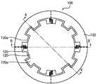
도 1은 본 발명의 일 실시예에 따른 멤스 마이크로폰을 설명하기 위한 개략적인 평면도이다.
도 2는 도 1의 절단선 A - A′에 따른 단면도이다.
도 3은 도 1의 절단선 B - B′에 따른 단면도이다.
도 4는 도 1에 도시된 지지부의 다른 예를 설명하기 위한 평면도이다.
도 5는 본 발명의 다른 실시예에 따른 멤스 마이크로폰을 설명하기 위한 개략적인 평면도이다.
도 6은 도 5의 절단선 C - C′에 따른 단면도이다.
도 7은 도 5의 절단선 D - D′에 따른 단면도이다.
도 8은 도 5에 도시된 진동판을 포함하는 평면을 기준으로 절단한 단면도이다.
도 9는 본 발명의 또 다른 실시예에 따른 멤스 마이크로폰을 설명하기 위한 개략적인 평면도이다.
도 10은 도 9의 절단선 E - E′에 따른 단면도이다.
도 11은 도 9의 절단선 F - F′에 따른 단면도이다.
도 12는 도 9에 도시된 진동판을 포함하는 평면을 기준으로 절단한 단면도이다.1 is a schematic plan view illustrating a MEMS microphone according to an embodiment of the present invention.
FIG. 2 is a cross-sectional view taken along the line A-A' of FIG. 1 .
FIG. 3 is a cross-sectional view taken along the line B-B' of FIG. 1;
4 is a plan view for explaining another example of the support shown in FIG. 1;
5 is a schematic plan view for explaining a MEMS microphone according to another embodiment of the present invention.
6 is a cross-sectional view taken along the cutting line C - C' of FIG. 5;
FIG. 7 is a cross-sectional view taken along the line D-D′ of FIG. 5 .
FIG. 8 is a cross-sectional view taken with reference to a plane including the diaphragm shown in FIG. 5 .
9 is a schematic plan view illustrating a MEMS microphone according to another embodiment of the present invention.
10 is a cross-sectional view taken along the cut line E - E' of FIG. 9 .
FIG. 11 is a cross-sectional view taken along the line F - F' of FIG. 9 .
FIG. 12 is a cross-sectional view taken with reference to a plane including the diaphragm shown in FIG. 9 .
이하, 본 발명의 실시예들은 첨부 도면들을 참조하여 상세하게 설명된다. 그러나, 본 발명은 하기에서 설명되는 실시예들에 한정된 바와 같이 구성되어야만 하는 것은 아니며 이와 다른 여러 가지 형태로 구체화될 수 있을 것이다. 하기의 실시예들은 본 발명이 온전히 완성될 수 있도록 하기 위하여 제공된다기보다는 본 발명의 기술 분야에서 숙련된 당업자들에게 본 발명의 범위를 충분히 전달하기 위하여 제공된다.Hereinafter, embodiments of the present invention will be described in detail with reference to the accompanying drawings. However, the present invention does not have to be configured as limited to the embodiments described below and may be embodied in various other forms. The following examples are not provided to fully complete the present invention, but rather to fully convey the scope of the present invention to those skilled in the art.
본 발명의 실시예들에서 하나의 요소가 다른 하나의 요소 상에 배치되는 또는 연결되는 것으로 설명되는 경우 상기 요소는 상기 다른 하나의 요소 상에 직접 배치되거나 연결될 수도 있으며, 다른 요소들이 이들 사이에 개재될 수도 있다. 이와 다르게, 하나의 요소가 다른 하나의 요소 상에 직접 배치되거나 연결되는 것으로 설명되는 경우 그들 사이에는 또 다른 요소가 있을 수 없다. 다양한 요소들, 조성들, 영역들, 층들 및/또는 부분들과 같은 다양한 항목들을 설명하기 위하여 제1, 제2, 제3 등의 용어들이 사용될 수 있으나, 상기 항목들은 이들 용어들에 의하여 한정되지는 않을 것이다.In the embodiments of the present invention, when one element is described as being disposed on or connected to another element, the element may be directly disposed on or connected to the other element, and other elements may be interposed therebetween. It could be. Alternatively, when an element is described as being directly disposed on or connected to another element, there cannot be another element between them. The terms first, second, third, etc. may be used to describe various items such as various elements, compositions, regions, layers and/or parts, but the items are not limited by these terms. will not
본 발명의 실시예들에서 사용된 전문 용어는 단지 특정 실시예들을 설명하기 위한 목적으로 사용되는 것이며, 본 발명을 한정하기 위한 것은 아니다. 또한, 달리 한정되지 않는 이상, 기술 및 과학 용어들을 포함하는 모든 용어들은 본 발명의 기술 분야에서 통상적인 지식을 갖는 당업자에게 이해될 수 있는 동일한 의미를 갖는다. 통상적인 사전들에서 한정되는 것들과 같은 상기 용어들은 관련 기술과 본 발명의 설명의 문맥에서 그들의 의미와 일치하는 의미를 갖는 것으로 해석될 것이며, 명확히 한정되지 않는 한 이상적으로 또는 과도하게 외형적인 직감으로 해석되지는 않을 것이다.Technical terms used in the embodiments of the present invention are only used for the purpose of describing specific embodiments, and are not intended to limit the present invention. In addition, unless otherwise limited, all terms including technical and scientific terms have the same meaning as can be understood by those skilled in the art having ordinary knowledge in the technical field of the present invention. The above terms, such as those defined in conventional dictionaries, shall be construed to have a meaning consistent with their meaning in the context of the relevant art and description of the present invention, unless expressly defined, ideally or excessively outwardly intuition. will not be interpreted.
본 발명의 실시예들은 본 발명의 이상적인 실시예들의 개략적인 도해들을 참조하여 설명된다. 이에 따라, 상기 도해들의 형상들로부터의 변화들, 예를 들면, 제조 방법들 및/또는 허용 오차들의 변화는 충분히 예상될 수 있는 것들이다. 따라서, 본 발명의 실시예들은 도해로서 설명된 영역들의 특정 형상들에 한정된 바대로 설명되어지는 것은 아니라 형상들에서의 편차를 포함하는 것이며, 도면들에 설명된 요소들은 전적으로 개략적인 것이며 이들의 형상은 요소들의 정확한 형상을 설명하기 위한 것이 아니며 또한 본 발명의 범위를 한정하고자 하는 것도 아니다.Embodiments of the present invention are described with reference to schematic illustrations of idealized embodiments of the present invention. Accordingly, variations from the shapes of the illustrations, eg, variations in manufacturing methods and/or tolerances, are fully foreseeable. Accordingly, embodiments of the present invention are not to be described as being limited to specific shapes of regions illustrated as diagrams, but to include variations in shapes, and elements described in the drawings are purely schematic and their shapes is not intended to describe the exact shape of the elements, nor is it intended to limit the scope of the present invention.
도 1은 본 발명의 일 실시예에 따른 멤스 마이크로폰을 설명하기 위한 개략적인 평면도이고, 도 2는 도 1의 절단선 A - A′에 따른 단면도이고, 도 3은 도 1의 절단선 B - B′에 따른 단면도이고, 도 4는 도 1에 도시된 지지부의 다른 예를 설명하기 위한 평면도이다.1 is a schematic plan view illustrating a MEMS microphone according to an embodiment of the present invention, FIG. 2 is a cross-sectional view taken along the line A-A' in FIG. 1, and FIG. 3 is the line B-B in FIG. It is a cross-sectional view along ', and Figure 4 is a plan view for explaining another example of the support shown in Figure 1.
도 1 내지 도 4를 참조하면, 상기 멤스 마이크로폰(100)은 음압에 따라 변위를 발생시켜 음을 전기 신호로 변환하여 출력한다. 상기 멤스 마이크로폰(100)은 기판(110), 진동판(120), 지지부들(125), 상대 전극들(130) 및 절연층들(140)을 포함할 수 있다.Referring to FIGS. 1 to 4 , the
상기 기판(110)은 중앙에 상하를 관통하는 캐비티(111)를 구비할 수 있다. 일 예로, 상기 캐비티(111)는 원 형상 또는 사각 형상일 수 있다.The
상기 진동판(120)은 상기 캐비티(111)의 상방에 배치되며, 상기 캐비티(112)를 통해 노출될 수 있다. 상기 진동판(120)은 음압에 의해 진동 가능하도록 상기 기판(110)으로부터 이격되어 위치한다. 상기 진동판(120)은 멤브레인으로 구성될 수 있으며, 음압을 감지하여 상하로 변위를 발생시킨다. 일 예로, 상기 진동판(120)은 상기 캐비티(111)와 동일한 형상일 수 있다. 상기 진동판(120)의 크기는 상기 캐비티(111)의 크기와 동일하거나 캐비티(111)의 크기보다 작을 수 있다.The
상기 진동판(120)은 폴리실리콘으로 이루어질 수 있다. 상기 진동판(120)은 이온 주입 공정을 통해 불순물 도핑이 이루어질 수 있다.The
상기 상대 전극들(130)은 상기 캐비티(111)를 제외한 상기 기판(110) 상에 구비된다. 상기 상대 전극들(130)은 상기 진동판(120)과 수평 방향으로 이격되도록 배치되며, 서로 절연되도록 상하로 적층되어 다층으로 이루어지며, 상기 진동판(120)의 상하 변위에 따라 복수의 전기 신호들을 발생한다.The
상기 상대 전극들(130)은 폴리실리콘으로 이루어질 수 있다. 상기 상대 전극들(130)은 이온 주입 공정을 통해 불순물 도핑이 이루어질 수 있다.The
구체적으로, 상기 상대 전극들(130)은 서로 다른 높이에 각각 위치하는 제1 상대 전극(131) 및 제2 상대 전극(133)을 포함할 수 있다. 제1 상대 전극(131) 및 제2 상대 전극(133)은 상기 진동판(120)을 둘러싸는 고리 형상을 가질 수 있다.Specifically, the
상기 진동판(120)은 상기 제1 상대 전극(131)과 상기 제2 상대 전극(133)의 사이의 높이에 위치할 수 있다. 예를 들면, 상기 진동판(120)과 상기 제1 상대 전극(131)의 높이 차이와 상기 진동판(120)과 상기 제2 상대 전극(133)의 높이 차이는 동일할 수 있다.The
상기 진동판(120)과 상기 상대 전극들(130)이 상기 수평 방향으로 이격되므로, 음압이 제공되거나 상기 진동판(120)이 하방으로 처짐이 발생하더라도 상기 진동판(120)과 상기 상대 전극들(130) 사이의 간격을 일정하게 유지할 수 있다. 따라서, 상기 멤스 마이크로폰(100)의 감도를 유지할 수 있다.Since the
상기 음압에 의해 상기 진동판(120)이 상하로 변위를 발생하면 상기 진동판(120)과 상기 상대 전극들(130) 사이에 정전 용량이 형성되면서 출력 신호들을 출력한다.When the
구체적으로, 상기 진동판(120)과 상기 제1 상대 전극(131) 사이에서 제1 출력 신호가 출력되고, 상기 진동판(120)과 상기 제2 상대 전극(133) 사이에서 제2 출력 신호가 출력된다. 따라서, 상기 멤스 마이크로폰(100)은 상기 출력 신호를 복수로 출력할 수 있다.Specifically, a first output signal is output between the
상기 출력 신호가 복수로 출력되므로, 상기 출력 신호들을 전달하거나 처리하는 과정에서 잡음을 감소시킬 수 있다. 예를 들면, 상기 제1 출력 신호와 상기 제2 출력 신호의 위상이 반대이므로, 상기 제1 출력 신호의 잡음과 상기 제2 출력 신호의 잡음을 중첩하여 전체적인 잡음을 감소시킬 수 있다. 따라서 상기 멤스 마이크로폰(100)의 성능을 향상시킬 수 있다.Since the output signals are output in plurality, noise can be reduced in the process of transmitting or processing the output signals. For example, since the phases of the first output signal and the second output signal are opposite, overall noise may be reduced by overlapping the noise of the first output signal with the noise of the second output signal. Therefore, the performance of the
상기 진동판(120)은 복수의 제1 돌기들(120a)을 포함하고, 상기 상대 전극들(130)은 상기 제1 돌기들(120a)과 맞물리는 제2 돌기들(130a)을 포함할 수 있다.The
상기 제1 돌기들(120a)은 상기 진동판(120)의 측면으로부터 수평 방향으로 돌출될 수 있다. 상기 제2 돌기들(130a)은 상기 제1 상대 전극(131)과 상기 제2 상대 전극(133)에 각각 구비될 수 있다.The
상기 제1 돌기들(120a)과 상기 제2 돌기들(130a)로 인해 상기 진동판(120)과 상기 상대 전극들(130)의 표면적을 증가시킬 수 있다. 또한, 상기 제1 돌기들(120a)과 상기 제2 돌기들(130a)이 서로 맞물리므로, 상기 진동판(120)과 상기 상대 전극들(130)의 대응 면적을 증가시킬 수 있다. 따라서, 상기 진동판(120)의 상기 변위가 발생하면 상기 진동판(120)과 상기 상대 전극들(130) 사이에서 발생하는 상기 정전 용량을 증가시킬 수 있다.Surface areas of the
상기 지지부들(125)은 상기 기판(110)의 상방에 구비되며, 상기 상대 전극들(130) 사이에서 상기 진동판(120)까지 연장한다. 이때, 상기 지지부들(125)은 상기 진동판(120)과 동일한 높이에 위치한다. 상기 지지부들(125)은 상기 진동판(120)이 상기 상대 전극들(130)과 이격된 상태를 유지하도록 상기 진동판(120)을 지지한다.The
상기 지지부들(125)은 복수로 구비되며, 상기 진동판(120)의 둘레를 따라 서로 이격되도록 배치될 수 있다. 상기 지지부들(125)이 서로 이격되므로, 상기 지지부들(125)이 상기 진동판(120)과 상기 상대 전극들(130) 사이를 차단하지 않는다. 따라서 음향 신호의 일부가 상기 진동판(120)과 상기 상대 전극들(130) 사이를 통과할 수 있다.The
상기 지지부들(125)은 상기 진동판(120)과 동일한 재질로 이루어질 수 있다. 즉, 상기 지지부들(125)은 폴리실리콘으로 이루어질 수 있다. 상기 지지부들(125)들 중 적어도 하나는 이온 주입 공정을 통해 불순물 도핑이 이루어질 수 있다. 상기 지지부들(125)은 상기 진동판(120)과 일체로 형성될 수 있다.The
일 예로, 상기 지지부들(125)은 스프링 구조를 가질 수 있다.(도 1 참조) 이때, 상기 스프링 구조는 수평 방향으로 구불구불한 형상을 갖거나, 상하 방향으로 구불구불한 형상을 가질 수 있다.For example, the
이와 달리 상기 지지부들(125)은 외팔보 구조를 가질 수 있다. (도 4 참조)Alternatively, the
상기 지지부들(125)은 상기 스프링 구조 또는 상기 외팔보 구조를 가지므로, 상기 지지부들(125)은 상기 진동판(120)을 탄성적으로 지지할 수 있다. 따라서 상기 진동판(120)의 상기 상하 변위를 증가시킬 수 있다.Since the
상기 절연층들(140)은 상기 기판(110), 상기 상대 전극들(120) 및 상기 지지부들(125) 사이에 각각 구비되며, 상기 기판(110), 상기 상대 전극들(120) 및 상기 지지부들(125)을 절연시킨다. 상기 절연층들(140)은 실리콘산화물, TEOS 등의 산화물로 이루어질 수 있다.The insulating
상기 절연층(140)은 제1 절연층(141), 제2 절연층(143) 및 제3 절연층(145)을 포함할 수 있다.The insulating
상기 제1 절연층(141)은 상기 기판(110)과 상기 제1 상대 전극(131) 사이에 구비되며, 상기 기판(110)과 상기 제1 상대 전극(131)을 절연시킨다.The first insulating
상기 제2 절연층(143)은 상기 제1 상대 전극(131)과 상기 지지부들(125) 사이에 구비되며, 상기 제1 상대 전극(131)과 상기 지지부들(125)을 절연시킨다.The second
상기 제3 절연층(145)은 상기 지지부들(125)의 측면과 상부면을 감싸면서 상기 제2 절연층(143)과 상기 제2 상대 전극(133) 사이에 구비된다. 따라서, 상기 제3 절연층(145)은 상기 지지부들(125)과 상기 제2 상대 전극(133)을 절연시킨다.The third
한편 도시되지는 않았지만, 상기 멤스 마이크로폰(100)은 상기 진동판(120)의 전기적 연결을 위한 제1 패드 및 상기 각 상대 전극들(130)의 전기적 연결을 위한 제2 패드들을 포함할 수 있다. 상기 제1 패드는 도핑된 상기 지지부(125)에 구비될 수 있다. 상기 제2 패드들은 상기 각 상대 전극들(130)에 구비될 수 있다.Meanwhile, although not shown, the
도 5는 본 발명의 다른 실시예에 따른 멤스 마이크로폰을 설명하기 위한 개략적인 평면도이고, 도 6은 도 5의 절단선 C - C′에 따른 단면도이고, 도 7은 도 5의 절단선 D - D′에 따른 단면도이고, 도 8은 도 5에 도시된 진동판을 포함하는 평면을 기준으로 절단한 단면도이다.5 is a schematic plan view for explaining a MEMS microphone according to another embodiment of the present invention, FIG. 6 is a cross-sectional view taken along the line C-C' in FIG. 5, and FIG. 7 is the line D-D in FIG. It is a cross-sectional view taken along ', and FIG. 8 is a cross-sectional view taken with respect to a plane including the diaphragm shown in FIG.
도 5 내지 도 8을 참조하면, 상기 멤스 마이크로폰(200)은 기판(210), 진동판(220), 지지부들(225), 상대 전극들(230) 및 절연층들(240)을 포함할 수 있다.5 to 8 , the
상기 진동판(220)이 상기 상대 전극들(230)의 제1 상대 전극(231)과 제2 상대 전극(233) 중 어느 하나의 높이와 동일한 높이에 위치하는 것을 제외하면, 상기 기판(210), 상기 진동판(220), 상기 지지부들(225) 및 상대 전극들(230)에 대한 설명은 도 1 내지 도 4를 참조한 기판(110), 진동판(120), 지지부들(125), 상대 전극들(130)에 대한 설명과 유사하므로 생략한다.Except that the
상기 진동판(220)은 상기 제1 상대 전극(231)과 동일한 높이에 위치하거나, 상기 제2 상대 전극(233)과 동일한 높이에 위치할 수 있다. 따라서, 상기 진동판(220)과 상기 제1 상대 전극(231)의 높이 차이와 상기 진동판(220)과 상기 제2 상대 전극(233)의 높이 차이가 다를 수 있다.The
이하에서는 상기 진동판(220)은 상기 제1 상대 전극(231)과 동일한 높이에 위치하는 경우에 대해 설명한다.Hereinafter, a case in which the
상기 음압에 의해 상기 진동판(220)이 상하로 변위를 발생하면 상기 진동판(220)과 상기 상대 전극들(230) 사이에 정전 용량이 형성되면서 출력 신호들을 출력한다.When the
구체적으로, 상기 진동판(220)과 상기 제1 상대 전극(231) 사이에서 제1 출력 신호가 출력되고, 상기 진동판(220)과 상기 제2 상대 전극(233) 사이에서 제2 출력 신호가 출력된다. 따라서, 상기 멤스 마이크로폰(200)은 상기 출력 신호를 복수로 출력할 수 있다.Specifically, a first output signal is output between the
상기 출력 신호가 복수로 출력되므로, 상기 출력 신호들을 전달하거나 처리하는 과정에서 잡음을 감소시킬 수 있다. 예를 들면, 상기 제1 출력 신호와 상기 제2 출력 신호의 위상이 차이가 있으므로, 상기 제1 출력 신호와 상기 제2 출력 신호의 위상 차이를 이용하여 전체적인 잡음을 감소시킬 수 있다. 따라서 상기 멤스 마이크로폰(200)의 성능을 향상시킬 수 있다.Since the output signals are output in plurality, noise can be reduced in the process of transmitting or processing the output signals. For example, since there is a phase difference between the first output signal and the second output signal, overall noise can be reduced using the phase difference between the first output signal and the second output signal. Therefore, the performance of the
상기 지지부들(225)은 상기 진동판(220)과 동일한 높이에 위치한다. 상기 진동판(220)이 상기 제1 상대 전극(231)과 동일한 높이에 위치하므로, 상기 지지부들(225)도 상기 제1 상대 전극(231)과 동일한 높이에 위치한다.The
상기 지지부들(225)과 상기 제1 상대 전극(231)이 전기적으로 연결되는 것을 방지하기 위해 상기 지지부들(225)과 상기 제1 상대 전극(231)은 수평 방향으로 서로 이격되어 배치될 수 있다. (도 8 참조)To prevent electrical connection between the
상기 절연층들(240)은 상기 기판(210), 상기 상대 전극들(220) 및 상기 지지부들(225) 사이에 각각 구비되며, 상기 기판(210), 상기 상대 전극들(220) 및 상기 지지부들(225)을 절연시킨다. 상기 절연층들(240)은 실리콘산화물, TEOS 등의 산화물로 이루어질 수 있다.The insulating
상기 절연층(240)은 제1 절연층(241) 및 제2 절연층(243)을 포함할 수 있다.The insulating
상기 제1 절연층(241)은 상기 기판(210)과 상기 제1 상대 전극(231) 사이 및 상기 기판(210)과 상기 지지부들(225) 사이에 구비되며, 상기 기판(210)과 상기 제1 상대 전극(231) 및 상기 기판(210)과 상기 지지부들(225)을 절연시킨다.The first insulating
상기 제2 절연층(243)은 상기 지지부들(225)과 상기 제1 상대 전극(231) 사이, 상기 지지부들(225)과 상기 제2 상대 전극(233) 사이 및 상기 제1 상대 전극(231)과 상기 제2 상대 전극(233) 사이에 구비되며, 상기 지지부들(225)과 상기 제1 상대 전극(231), 상기 지지부들(225)과 상기 제2 상대 전극(233) 및 상기 제1 상대 전극(231)과 상기 제2 상대 전극(233)을 절연시킨다.The second
한편 도시되지는 않았지만, 상기 멤스 마이크로폰(200)은 상기 진동판(220)의 전기적 연결을 위한 제1 패드 및 상기 각 상대 전극들(230)의 전기적 연결을 위한 제2 패드들을 포함할 수 있다. 상기 제1 패드는 도핑된 상기 지지부(225)에 구비될 수 있다. 상기 제2 패드들은 상기 각 상대 전극들(230)에 구비될 수 있다.Meanwhile, although not shown, the
도 9는 본 발명의 또 다른 실시예에 따른 멤스 마이크로폰을 설명하기 위한 개략적인 평면도이고, 도 10은 도 9의 절단선 E - E′에 따른 단면도이고, 도 11은 도 9의 절단선 F - F′에 따른 단면도이고, 도 12는 도 9에 도시된 진동판을 포함하는 평면을 기준으로 절단한 단면도이다.9 is a schematic plan view for explaining a MEMS microphone according to another embodiment of the present invention, FIG. 10 is a cross-sectional view taken along the line E-E' in FIG. 9, and FIG. 11 is the line F-E in FIG. A cross-sectional view taken along F', and FIG. 12 is a cross-sectional view taken with respect to a plane including the diaphragm shown in FIG. 9 .
도 9 내지 도 12를 참조하면, 상기 멤스 마이크로폰(300)은 기판(310), 진동판(320), 지지부들(325), 상대 전극들(330) 및 절연층들(340)을 포함할 수 있다.9 to 12 , the
상기 상대 전극들(330)은 서로 다른 높이에 순차적으로 각각 위치하는 제1 상대 전극(331), 제2 상대 전극(333) 및 제3 상대 전극(333)을 포함하고, 상기 진동판(320)이 상기 상대 전극들(330)의 상기 제2 상대 전극(333)의 높이와 동일한 높이에 위치하는 것을 제외하면, 상기 기판(310), 상기 진동판(320), 상기 지지부들(325) 및 상대 전극들(330)에 대한 설명은 도 1 내지 도 4를 참조한 기판(110), 진동판(120), 지지부들(125), 상대 전극들(130)에 대한 설명과 유사하므로 생략한다.The
상기 진동판(320)은 상기 제2 상대 전극(333)의 높이와 동일한 높이에 위치할 수 있다. 따라서, 상기 진동판(320)과 상기 제1 상대 전극(331)의 높이 차이와 상기 진동판(320)과 상기 제3 상대 전극(333)의 높이 차이가 동일하다.The
상기 음압에 의해 상기 진동판(320)이 상하로 변위를 발생하면 상기 진동판(320)과 상기 상대 전극들(330) 사이에 정전 용량이 형성되면서 출력 신호들을 출력한다.When the
구체적으로, 상기 진동판(320)과 상기 제1 상대 전극(331) 사이에서 제1 출력 신호가 출력되고, 상기 진동판(320)과 상기 제2 상대 전극(333) 사이에서 제2 출력 신호가 출력되고, 상기 진동판(320)과 상기 제3 상대 전극(335) 사이에서 제3 출력 신호가 출력된다. 따라서, 상기 멤스 마이크로폰(300)은 상기 출력 신호를 복수로 출력할 수 있다.Specifically, a first output signal is output between the
상기 출력 신호가 복수로 출력되므로, 상기 출력 신호들을 전달하거나 처리하는 과정에서 잡음을 감소시킬 수 있다. 예를 들면, 상기 제1 출력 신호와 상기 제3 출력 신호의 위상이 반대이고, 상기 제2 출력 신호는 상기 제1 출력 신호 및 상기 제3 출력 신호와 위상 차이가 있다. 상기 제1 출력 신호의 잡음과 상기 제3 출력 신호의 잡음을 중첩하여 전체적인 잡음을 감소시킬 수 있다, 또한, 상기 제2 출력 신호의 위상과 상기 제1 출력 신호 및 상기 제3 출력 신호의 위상 차이를 이용하여 전체적인 잡음을 감소시킬 수 있다. 따라서 상기 멤스 마이크로폰(300)의 성능을 향상시킬 수 있다.Since the output signals are output in plurality, noise can be reduced in the process of transmitting or processing the output signals. For example, the phases of the first output signal and the third output signal are opposite, and the second output signal is out of phase with the first output signal and the third output signal. The noise of the first output signal and the noise of the third output signal may be overlapped to reduce overall noise, and the phase difference between the phase of the second output signal and the phase of the first output signal and the third output signal The overall noise can be reduced by using . Therefore, the performance of the
상기 지지부들(325)은 상기 진동판(320)과 동일한 높이에 위치한다. 상기 진동판(320)이 상기 제2 상대 전극(333)과 동일한 높이에 위치하므로, 상기 지지부들(325)도 상기 제2 상대 전극(333)과 동일한 높이에 위치한다.The
상기 지지부들(325)과 상기 제2 상대 전극(333)이 전기적으로 연결되는 것을 방지하기 위해 상기 지지부들(325)과 상기 제2 상대 전극(333)은 수평 방향으로 서로 이격되어 배치될 수 있다. (도 12 참조)To prevent electrical connection between the
상기 절연층들(340)은 상기 기판(310), 상기 상대 전극들(320) 및 상기 지지부들(325) 사이에 각각 구비되며, 상기 기판(310), 상기 상대 전극들(320) 및 상기 지지부들(325)을 절연시킨다. 상기 절연층들(340)은 실리콘산화물, TEOS 등의 산화물로 이루어질 수 있다.The insulating
상기 절연층(340)은 제1 절연층(341), 제2 절연층(343) 및 제3 절연층(345)을 포함할 수 있다.The insulating
상기 제1 절연층(341)은 상기 기판(310)과 상기 제3 상대 전극(131) 사이에 구비되며, 상기 기판(310)과 상기 제1 상대 전극(331)을 절연시킨다.The first insulating
상기 제2 절연층(343)은 상기 제1 상대 전극(331)과 상기 제2 상대 전극(333) 사이 및 상기 제1 상대 전극(331)과 상기 지지부들(325) 사이에 구비되며, 상기 제1 상대 전극(331)과 상기 제2 상대 전극(333) 및 상기 제1 상대 전극(331)과 상기 지지부들(325)을 절연시킨다.The second
상기 제2 절연층(343)은 상기 지지부들(325)과 상기 제2 상대 전극(333) 사이, 상기 지지부들(325)과 상기 제3 상대 전극(335) 사이 및 상기 제2 상대 전극(333)과 상기 제3 상대 전극(335) 사이에 구비되며, 상기 지지부들(325)과 상기 제2 상대 전극(333), 상기 지지부들(325)과 상기 제3 상대 전극(335) 및 상기 제2 상대 전극(333)과 상기 제3 상대 전극(335)을 절연시킨다.The second
한편 도시되지는 않았지만, 상기 멤스 마이크로폰(300)은 상기 진동판(320)의 전기적 연결을 위한 제1 패드 및 상기 각 상대 전극들(330)의 전기적 연결을 위한 제2 패드들을 포함할 수 있다. 상기 제1 패드는 도핑된 상기 지지부(325)에 구비될 수 있다. 상기 제2 패드들은 상기 각 상대 전극들(330)에 구비될 수 있다.Meanwhile, although not shown, the
상술한 바와 같이, 본 발명의 실시예들에 따르면, 상기 진동판과 상기 상대 전극들이 상기 수평 방향으로 이격되므로, 음압이 제공되더라도 상기 진동판과 상기 상대 전극들 사이의 간격을 일정하게 유지할 수 있다. 따라서, 상기 멤스 마이크로폰의 감도를 유지할 수 있다.As described above, according to embodiments of the present invention, since the diaphragm and the counter electrodes are spaced apart in the horizontal direction, even when a negative pressure is applied, the distance between the diaphragm and the counter electrodes may be maintained constant. Therefore, the sensitivity of the MEMS microphone can be maintained.
또한, 상기 상대 전극이 상기 다층으로 이루어지므로, 상기 멤스 마이크로폰은 상기 출력 신호를 복수로 출력할 수 있다. 상기 출력 신호가 복수로 출력되므로, 상기 출력 신호들을 전달하거나 처리하는 과정에서 잡음을 감소시킬 수 있다. 따라서 상기 멤스 마이크로폰의 성능을 향상시킬 수 있다.In addition, since the counter electrode is formed of the multilayer, the MEMS microphone can output a plurality of output signals. Since the output signals are output in plurality, noise can be reduced in the process of transmitting or processing the output signals. Accordingly, the performance of the MEMS microphone can be improved.
한편, 음압에 의해 상기 진동판과 상기 상대 전극들이 접착되는 것을 방지할 수 있으므로, 종래와 달리 상기 상대 전극들에 딤플들을 형성하거나, 상기 진동판과 상기 상대 전극들에 소수성 물질을 도포할 필요가 없다. 따라서, 상기 멤스 마이크로폰의 구조를 단순화하거나, 상기 멤스 마이크로폰의 제조 비용을 줄일 수 있다.Meanwhile, since adhesion between the diaphragm and the counter electrodes can be prevented by negative pressure, there is no need to form dimples on the counter electrodes or to apply a hydrophobic material to the diaphragm and the counter electrodes unlike in the prior art. Accordingly, the structure of the MEMS microphone may be simplified or the manufacturing cost of the MEMS microphone may be reduced.
상기에서는 본 발명의 바람직한 실시예를 참조하여 설명하였지만, 해당 기술 분야의 숙련된 당업자는 하기의 청구범위에 기재된 본 발명의 사상 및 영역으로부터 벗어나지 않는 범위 내에서 본 발명을 다양하게 수정 및 변경시킬 수 있음을 이해할 수 있을 것이다.Although the above has been described with reference to preferred embodiments of the present invention, those skilled in the art can variously modify and change the present invention without departing from the spirit and scope of the present invention described in the claims below. You will understand that there is
100, 200, 300 : 멤스 마이크로폰
110, 210, 310 : 기판
111, 211, 311 : 캐비티
120, 220, 320 : 진동판
120a, 220a, 320a : 제1 돌기
125, 225, 325 : 지지부
130, 230, 330 : 상대 전극
130a, 230a, 330a : 제2 돌기
131, 231, 331 : 제1 상대 전극
133, 233, 333 : 제2 상대 전극
335 : 제3 상대 전극
140, 240, 340 : 절연층
141, 241, 341 : 제1 절연층
143, 243, 343 : 제2 절연층
145, 245, 345 : 제3 절연층100, 200, 300: MEMS microphone
110, 210, 310: substrate
111, 211, 311: cavity
120, 220, 320: diaphragm
120a, 220a, 320a: first protrusion
125, 225, 325: support
130, 230, 330: counter electrode
130a, 230a, 330a: second projection
131, 231, 331: first counter electrode
133, 233, 333: second counter electrode
335: third counter electrode
140, 240, 340: insulating layer
141, 241, 341: first insulating layer
143, 243, 343: second insulating layer
145, 245, 345: third insulating layer
Claims (15)
Translated fromKorean상기 진동판과 수평 방향으로 이격되도록 배치되며, 서로 절연되도록 상하로 적층되어 다층으로 이루어지며, 상기 진동판의 상하 변위에 따라 복수의 전기 신호들을 발생하는 상대 전극들을 포함하는 것을 특징으로 하는 멤스 마이크로폰.a diaphragm vibrating up and down by sound pressure; and
The MEMS microphone of claim 1, further comprising counter electrodes arranged to be spaced apart from the diaphragm in a horizontal direction, stacked vertically to be insulated from each other, and formed of multiple layers, and generating a plurality of electrical signals according to vertical displacement of the diaphragm.
상기 진동판은 상기 제1 상대 전극과 상기 제2 상대 전극의 사이의 높이에 위치하는 것을 특징으로 하는 멤스 마이크로폰.The method of claim 1, wherein the counter electrodes include a first counter electrode and a second counter electrode positioned at different heights,
The MEMS microphone, characterized in that the diaphragm is located at a height between the first counter electrode and the second counter electrode.
상기 진동판은 상기 제1 상대 전극과 상기 제2 상대 전극 중 어느 하나의 높이와 동일한 높이에 위치하는 것을 특징으로 하는 멤스 마이크로폰.The method of claim 1, wherein the counter electrodes include a first counter electrode and a second counter electrode positioned at different heights,
The MEMS microphone, characterized in that the diaphragm is located at the same height as the height of any one of the first counter electrode and the second counter electrode.
상기 진동판은 상기 제2 상대 전극이 높이와 동일한 높이에 위치하는 것을 특징으로 하는 멤스 마이크로폰.The method of claim 1, wherein the counter electrodes include a first counter electrode, a second counter electrode, and a third counter electrode sequentially positioned at different heights,
The MEMS microphone, characterized in that the diaphragm is positioned at the same height as the height of the second counter electrode.
상기 캐비티의 상방에 배치되며, 음압에 의해 상하로 진동하는 진동판;
상기 기판 상에 상기 진동판과 수평 방향으로 이격되도록 배치되며, 서로 절연되도록 상하로 적층되어 다층으로 이루어지며, 상기 진동판의 상하 변위에 따라 복수의 전기 신호들을 발생하는 상대 전극들;
상기 상대 전극들 사이에서 상기 진동판가지 연장하며, 상기 진동판이 상기 상대 전극들과 이격된 상태를 유지하도록 상기 진동판을 지지하는 지지부들: 및
상기 기판, 상기 상대 전극들 및 상기 지지부들 사이에 각각 구비되며, 상기 기판, 상기 상대 전극들 및 상기 지지부들을 절연시키는 절연층들을 포함하는 것을 특징으로 하는 멤스 마이크로폰.Substrates with a central cavity:
a diaphragm disposed above the cavity and vibrating up and down by sound pressure;
Counter electrodes disposed on the substrate to be spaced apart from the diaphragm in a horizontal direction, stacked vertically to be insulated from each other, and having multiple layers, generating a plurality of electrical signals according to the vertical displacement of the diaphragm;
The diaphragm extends between the counter electrodes and supports the diaphragm so that the diaphragm remains spaced apart from the counter electrodes; and
and insulating layers provided between the substrate, the counter electrodes, and the support parts, and insulating the substrate, the counter electrodes, and the support parts.
상기 진동판은 상기 제1 상대 전극과 상기 제2 상대 전극의 사이의 높이에 위치하는 것을 특징으로 하는 멤스 마이크로폰.13. The method of claim 12, wherein the counter electrode comprises a first counter electrode and a second counter electrode respectively positioned at different heights,
The MEMS microphone, characterized in that the diaphragm is located at a height between the first counter electrode and the second counter electrode.
상기 진동판은 상기 제1 상대 전극과 상기 제2 상대 전극 중 어느 하나의 높이와 동일한 높이에 위치하는 것을 특징으로 하는 멤스 마이크로폰.13. The method of claim 12, wherein the counter electrode comprises a first counter electrode and a second counter electrode respectively positioned at different heights,
The MEMS microphone, characterized in that the diaphragm is located at the same height as the height of any one of the first counter electrode and the second counter electrode.
상기 진동판은 상기 제2 상대 전극이 높이와 동일한 높이에 위치하는 것을 특징으로 하는 멤스 마이크로폰.13. The method of claim 12, wherein the counter electrode includes a first counter electrode, a second counter electrode, and a third counter electrode sequentially positioned at different heights,
The MEMS microphone, characterized in that the diaphragm is positioned at the same height as the height of the second counter electrode.
Priority Applications (2)
| Application Number | Priority Date | Filing Date | Title |
|---|---|---|---|
| KR1020210088307AKR20230007678A (en) | 2021-07-06 | 2021-07-06 | MEMS microphone |
| US17/810,107US20230011400A1 (en) | 2021-07-06 | 2022-06-30 | Mems microphone |
Applications Claiming Priority (1)
| Application Number | Priority Date | Filing Date | Title |
|---|---|---|---|
| KR1020210088307AKR20230007678A (en) | 2021-07-06 | 2021-07-06 | MEMS microphone |
Publications (1)
| Publication Number | Publication Date |
|---|---|
| KR20230007678Atrue KR20230007678A (en) | 2023-01-13 |
Family
ID=84798438
Family Applications (1)
| Application Number | Title | Priority Date | Filing Date |
|---|---|---|---|
| KR1020210088307AWithdrawnKR20230007678A (en) | 2021-07-06 | 2021-07-06 | MEMS microphone |
Country Status (2)
| Country | Link |
|---|---|
| US (1) | US20230011400A1 (en) |
| KR (1) | KR20230007678A (en) |
Family Cites Families (13)
| Publication number | Priority date | Publication date | Assignee | Title |
|---|---|---|---|---|
| CN101346014B (en)* | 2007-07-13 | 2012-06-20 | 清华大学 | Micro electro-mechanical system microphone and preparation method thereof |
| KR101065292B1 (en)* | 2008-12-22 | 2011-09-19 | 한국전자통신연구원 | MEMS microphone and its manufacturing method |
| US8847289B2 (en)* | 2010-07-28 | 2014-09-30 | Goertek Inc. | CMOS compatible MEMS microphone and method for manufacturing the same |
| US9681234B2 (en)* | 2013-05-09 | 2017-06-13 | Shanghai Ic R&D Center Co., Ltd | MEMS microphone structure and method of manufacturing the same |
| CN106303867B (en)* | 2015-05-13 | 2019-02-01 | 无锡华润上华科技有限公司 | MEMS microphone |
| CN104883652B (en)* | 2015-05-29 | 2019-04-12 | 歌尔股份有限公司 | MEMS microphone, pressure sensor integrated morphology and its manufacturing method |
| CN107105377B (en)* | 2017-05-15 | 2021-01-22 | 潍坊歌尔微电子有限公司 | A MEMS microphone |
| KR20190016718A (en)* | 2017-08-09 | 2019-02-19 | 주식회사 디비하이텍 | MEMS microphone and method of manufacturing the same |
| KR102370648B1 (en)* | 2017-08-09 | 2022-03-07 | 주식회사 디비하이텍 | MEMS microphone and method of manufacturing the same |
| KR102424774B1 (en)* | 2017-09-11 | 2022-07-25 | 주식회사 디비하이텍 | MEMS microphone and method of manufacturing the same |
| KR20200118545A (en)* | 2019-04-08 | 2020-10-16 | 주식회사 디비하이텍 | MEMS microphone and method of manufacturing the same |
| KR102665104B1 (en)* | 2019-04-16 | 2024-05-13 | 주식회사 디비하이텍 | MEMS microphone and method of manufacturing the same |
| US12351450B2 (en)* | 2021-04-19 | 2025-07-08 | Skyworks Solutions, Inc. | Dual membrane piezoelectric microelectromechanical system microphone |
- 2021
- 2021-07-06KRKR1020210088307Apatent/KR20230007678A/ennot_activeWithdrawn
- 2022
- 2022-06-30USUS17/810,107patent/US20230011400A1/ennot_activeAbandoned
Also Published As
| Publication number | Publication date |
|---|---|
| US20230011400A1 (en) | 2023-01-12 |
Similar Documents
| Publication | Publication Date | Title |
|---|---|---|
| US11553282B2 (en) | Differential condenser microphone with double vibrating membranes | |
| CN103288040B (en) | The manufacture method of tunable MEMS device and tunable MEMS device | |
| KR100899482B1 (en) | Silicon microphone and manufacturing method therefor | |
| KR101462375B1 (en) | MEMS Microphone | |
| US20090185700A1 (en) | Vibration transducer and manufacturing method therefor | |
| US20150041930A1 (en) | Acoustic transducer | |
| US20170339494A1 (en) | Mems acoustic transducer with combfingered electrodes and corresponding manufacturing process | |
| US10993043B2 (en) | MEMS acoustic sensor | |
| US20190245133A1 (en) | Piezoelectric device | |
| JP2012175509A (en) | Acoustic sensor and microphone | |
| KR20190016716A (en) | MEMS microphone and method of manufacturing the same | |
| KR100648398B1 (en) | Packaging Structure of Silicon Condenser Microphone and Manufacturing Method Thereof | |
| US11405731B1 (en) | Microelectromechanical system | |
| US11889282B2 (en) | MEMS device | |
| WO2022142507A1 (en) | Mems microphone and diaphragm structure thereof | |
| US20250250157A1 (en) | Mems transducer | |
| JP2023158628A (en) | MEMS elements and electroacoustic transducers | |
| KR20160001453A (en) | Microphone | |
| KR20230007678A (en) | MEMS microphone | |
| KR102091854B1 (en) | Condensor microphone and manufacturing method thereof | |
| US12022272B2 (en) | MEMS device | |
| JP2018133384A (en) | Piezoelectric element | |
| KR101688954B1 (en) | Method of Manufacturing Microphone Having Advanced Membrane Support System and Method of Manufacturing the Same | |
| JP7287597B2 (en) | MEMS element | |
| KR101816253B1 (en) | Voice transmitting device and manufacturing method thereof |
Legal Events
| Date | Code | Title | Description |
|---|---|---|---|
| PA0109 | Patent application | St.27 status event code:A-0-1-A10-A12-nap-PA0109 | |
| PG1501 | Laying open of application | St.27 status event code:A-1-1-Q10-Q12-nap-PG1501 | |
| PC1203 | Withdrawal of no request for examination | St.27 status event code:N-1-6-B10-B12-nap-PC1203 |