KR20230006106A - Method and apparatus for generating high depth of field image, apparatus for training high depth of field image generation model using stereo image - Google Patents
Method and apparatus for generating high depth of field image, apparatus for training high depth of field image generation model using stereo imageDownload PDFInfo
- Publication number
- KR20230006106A KR20230006106AKR1020210086859AKR20210086859AKR20230006106AKR 20230006106 AKR20230006106 AKR 20230006106AKR 1020210086859 AKR1020210086859 AKR 1020210086859AKR 20210086859 AKR20210086859 AKR 20210086859AKR 20230006106 AKR20230006106 AKR 20230006106A
- Authority
- KR
- South Korea
- Prior art keywords
- depth
- image
- deep
- data
- region
- Prior art date
- Legal status (The legal status is an assumption and is not a legal conclusion. Google has not performed a legal analysis and makes no representation as to the accuracy of the status listed.)
- Granted
Links
Images


Classifications
- G—PHYSICS
- G06—COMPUTING OR CALCULATING; COUNTING
- G06T—IMAGE DATA PROCESSING OR GENERATION, IN GENERAL
- G06T5/00—Image enhancement or restoration
- G06T5/73—Deblurring; Sharpening
- G—PHYSICS
- G06—COMPUTING OR CALCULATING; COUNTING
- G06T—IMAGE DATA PROCESSING OR GENERATION, IN GENERAL
- G06T7/00—Image analysis
- G06T7/10—Segmentation; Edge detection
- G06T7/11—Region-based segmentation
- G—PHYSICS
- G06—COMPUTING OR CALCULATING; COUNTING
- G06N—COMPUTING ARRANGEMENTS BASED ON SPECIFIC COMPUTATIONAL MODELS
- G06N20/00—Machine learning
- G—PHYSICS
- G06—COMPUTING OR CALCULATING; COUNTING
- G06T—IMAGE DATA PROCESSING OR GENERATION, IN GENERAL
- G06T7/00—Image analysis
- G06T7/50—Depth or shape recovery
- G—PHYSICS
- G06—COMPUTING OR CALCULATING; COUNTING
- G06T—IMAGE DATA PROCESSING OR GENERATION, IN GENERAL
- G06T7/00—Image analysis
- G06T7/50—Depth or shape recovery
- G06T7/55—Depth or shape recovery from multiple images
- G06T7/593—Depth or shape recovery from multiple images from stereo images
- G—PHYSICS
- G06—COMPUTING OR CALCULATING; COUNTING
- G06T—IMAGE DATA PROCESSING OR GENERATION, IN GENERAL
- G06T2207/00—Indexing scheme for image analysis or image enhancement
- G06T2207/10—Image acquisition modality
- G06T2207/10004—Still image; Photographic image
- G06T2207/10012—Stereo images
- G—PHYSICS
- G06—COMPUTING OR CALCULATING; COUNTING
- G06T—IMAGE DATA PROCESSING OR GENERATION, IN GENERAL
- G06T2207/00—Indexing scheme for image analysis or image enhancement
- G06T2207/10—Image acquisition modality
- G06T2207/10056—Microscopic image
- G—PHYSICS
- G06—COMPUTING OR CALCULATING; COUNTING
- G06T—IMAGE DATA PROCESSING OR GENERATION, IN GENERAL
- G06T2207/00—Indexing scheme for image analysis or image enhancement
- G06T2207/20—Special algorithmic details
- G06T2207/20081—Training; Learning
- G—PHYSICS
- G06—COMPUTING OR CALCULATING; COUNTING
- G06T—IMAGE DATA PROCESSING OR GENERATION, IN GENERAL
- G06T2207/00—Indexing scheme for image analysis or image enhancement
- G06T2207/20—Special algorithmic details
- G06T2207/20084—Artificial neural networks [ANN]
- G—PHYSICS
- G06—COMPUTING OR CALCULATING; COUNTING
- G06T—IMAGE DATA PROCESSING OR GENERATION, IN GENERAL
- G06T2207/00—Indexing scheme for image analysis or image enhancement
- G06T2207/30—Subject of image; Context of image processing
- G06T2207/30004—Biomedical image processing
- G06T2207/30024—Cell structures in vitro; Tissue sections in vitro
Landscapes
- Engineering & Computer Science (AREA)
- Theoretical Computer Science (AREA)
- Physics & Mathematics (AREA)
- General Physics & Mathematics (AREA)
- Computer Vision & Pattern Recognition (AREA)
- Software Systems (AREA)
- Medical Informatics (AREA)
- Evolutionary Computation (AREA)
- Data Mining & Analysis (AREA)
- Artificial Intelligence (AREA)
- Computing Systems (AREA)
- General Engineering & Computer Science (AREA)
- Mathematical Physics (AREA)
- Image Analysis (AREA)
- Image Processing (AREA)
- Investigating Or Analysing Biological Materials (AREA)
- Apparatus Associated With Microorganisms And Enzymes (AREA)
- Measuring Or Testing Involving Enzymes Or Micro-Organisms (AREA)
- Micro-Organisms Or Cultivation Processes Thereof (AREA)
Abstract
Description
Translated fromKorean본 발명은 고심도 영상 생성 방법 및 장치, 고심도 영상 생성 모델 학습 장치에 관한 것이다.The present invention relates to a method and apparatus for generating a deep-depth image, and an apparatus for learning a model for generating a deep-depth image.
현미경은 사람의 눈으로 관찰하기 힘든 미세한 물체나 미생물을 확대하여 관찰하는 기구이다. 현미경과 연동되어 사용되는 슬라이드 스캐너(Slide Scanner)는 하나 또는 복수의 슬라이드를 자동으로 스캔하여 이미지를 저장 및 관찰 분석할 수 있는 장치이다. 일반적으로 현미경은 조직이나 세포 촬영 등을 위해 고배율 렌즈를 사용하므로, 심도(depth of field)가 낮아 여러 높이에 분포하는 세포들을 동시에 촬영하기 어렵다. 이를테면, 병리 검사에서 4um 두께의 조직 시편을 사용할 경우, 40배 대물렌즈의 초점 심도는 최대 1um 수준인데, 단일 촬영 영역에 두 개 이상의 세포들이 1um 이상의 높이 차이를 가지고 분포한다면 이 세포들을 한 장의 영상에서 모두 초점이 맞도록 촬영하기 어렵다. 또한 평면이 아닌 입체적인 형태를 갖는 물체를 촬영해야 하기 때문에, 울퉁불퉁한 표면에 초점을 맞출 수 있어야 한다. 일반적으로 영상 내 많은 세포들은 서로 다른 위치에 존재하므로, 전체적으로 초점이 맞는 영상을 얻기가 어렵다.A microscope is an instrument that magnifies and observes minute objects or microorganisms that are difficult to observe with the human eye. A slide scanner used in conjunction with a microscope is a device capable of automatically scanning one or a plurality of slides to save, observe, and analyze images. In general, since a microscope uses a high-magnification lens for tissue or cell imaging, it is difficult to simultaneously image cells distributed at various heights due to a low depth of field. For example, when a tissue specimen with a thickness of 4um is used in a pathology examination, the depth of focus of a 40x objective lens is at most 1um. It is difficult to take a picture so that everything is in focus. Also, since you need to shoot an object that has a three-dimensional shape rather than a flat surface, you need to be able to focus on the bumpy surface. In general, since many cells in an image are located at different locations, it is difficult to obtain an image that is entirely in focus.
따라서 현미경이나 슬라이드 스캐너에서 고심도(high depth of field) 영상을 얻기 위해, x, y축이 고정된 위치에서 z축의 초점면을 변경하면서 다수의 영상을 촬영한 다음 이들을 합성하는 z-stack(focus stack) 기법이 사용된다.Therefore, in order to obtain a high depth of field image from a microscope or slide scanner, a z-stack (focus stack) technique is used.
그러나 이러한 z-stack 기법은 z축의 초점면 변경을 위해 다른 심도의 복수의 촬영을 위한 광학 구조를 갖추어야 하고 매우 많은 초점면을 반복적으로 판단, 변경, 촬영하고 합성해야 하므로 촬영 시간이 오래 소요되는 등 여러 문제점을 가지고 있다. 또한 레이저 등의 기술을 사용해 초점을 맞출 거리(깊이)를 파악하는 방식도 영상 기반의 초점 판단이 필요한 대상을 촬영하는 경우에는 적합하지 않은 기술이다.However, this z-stack technique requires an optical structure for multiple shots at different depths to change the focal plane in the z-axis, and requires a lot of focal planes to be repeatedly judged, changed, photographed, and synthesized, so it takes a long time to shoot. has several problems. In addition, the method of determining the distance (depth) to be focused using a technology such as a laser is not suitable for shooting an object that requires image-based focus determination.
본 발명이 이루고자 하는 기술적 과제는, 다른 심도의 복수의 촬영을 위한 광학 구조가 요구되지 않고, 촬영된 영상으로부터 고심도 영상을 생성할 수 있는 고심도 영상 생성 방법 및 장치, 그리고 이를 위한 고심도 영상 생성 모델 학습 장치를 제공하는 데 있다.A technical problem to be achieved by the present invention is a method and apparatus for generating a high-depth image that can generate a high-depth image from a captured image without requiring an optical structure for a plurality of shots at different depths, and a high-depth image for this purpose. It is to provide a generative model learning device.
상기 기술적 과제를 해결하기 위한 본 발명에 따른 고심도 영상 생성 장치는, 스테레오 영상에 대하여 영역을 분할하여 영역 데이터를 생성하는 영역 분할부; 상기 스테레오 영상에 대하여 깊이를 추정하여 깊이 데이터를 생성하는 깊이 추정부; 및 상기 스테레오 영상, 상기 영역 데이터, 및 상기 깊이 데이터로부터 고심도 영상을 생성하는 고심도 영상 생성부를 포함한다.An apparatus for generating a high-depth image according to the present invention for solving the above technical problems includes a region dividing unit generating region data by dividing regions of a stereo image; a depth estimation unit generating depth data by estimating a depth of the stereo image; and a deep-depth image generating unit generating a deep-depth image from the stereo image, the region data, and the depth data.
상기 고심도 영상 생성부는 학습된 딥러닝 모델을 이용하여 상기 고심도 영상을 생성할 수 있다.The deep-depth image generating unit may generate the deep-depth image using a learned deep learning model.
상기 영역 분할부 또는 상기 깊이 추정부는 학습된 딥러닝 모델을 이용하여 상기 영역 데이터 또는 상기 깊이 데이터를 생성할 수 있다.The region divider or the depth estimator may generate the region data or the depth data using a learned deep learning model.
상기 영역 분할부는 상기 스테레오 영상을 구성하는 각 영상 별로 영역을 분할하여 영역 데이터를 생성하고, 상기 깊이 추정부는 분할된 각 영역 별로 깊이 데이터를 생성할 수 있다.The region dividing unit may generate region data by dividing regions for each image constituting the stereo image, and the depth estimation unit may generate depth data for each divided region.
상기 스테레오 영상은 조직 또는 세포를 촬영한 영상일 수 있다.The stereo image may be an image of a tissue or cell.
상기 학습된 딥러닝 모델은 점 확산 함수(Point-Spread Function)를 이용한 블라인드 디컨볼루션(blind deconvolution)을 모사하도록 구현될 수 있다.The learned deep learning model may be implemented to simulate blind deconvolution using a point-spread function.
상기 기술적 과제를 해결하기 위한 본 발명에 따른 고심도 영상 생성 방법은, 스테레오 영상에 대하여 영역을 분할하여 영역 데이터를 생성하는 영역 분할 과정; 상기 스테레오 영상에 대하여 깊이를 추정하여 깊이 데이터를 생성하는 깊이 추정 과정; 및 상기 스테레오 영상, 상기 영역 데이터, 및 상기 깊이 데이터로부터 고심도 영상을 생성하는 고심도 영상 생성 과정을 포함할 수 있다.A method for generating a deep-depth image according to the present invention for solving the above technical problems includes a region segmentation process of generating region data by dividing a region of a stereo image; a depth estimation process of generating depth data by estimating a depth of the stereo image; and a deep-depth image generating process of generating a deep-depth image from the stereo image, the region data, and the depth data.
상기 고심도 영상 생성 과정은 학습된 딥러닝 모델을 이용할 수 있다.The high-depth image generation process may use a learned deep learning model.
상기 영역 분할 과정 또는 상기 깊이 추정 과정은 학습된 딥러닝 모델을 이용할 수 있다.The region segmentation process or the depth estimation process may use a learned deep learning model.
상기 영역 분할부는 상기 스테레오 영상을 구성하는 각 영상 별로 영역을 분할하여 영역 데이터를 생성하고, 상기 깊이 추정부는 분할된 각 영역 별로 깊이 데이터를 생성할 수 있다.The region dividing unit may generate region data by dividing regions for each image constituting the stereo image, and the depth estimation unit may generate depth data for each divided region.
상기 스테레오 영상은 조직 또는 세포를 촬영한 영상일 수 있다.The stereo image may be an image of a tissue or cell.
상기 학습된 딥러닝 모델은 점 확산 함수(Point-Spread Function)를 이용한 블라인드 디컨볼루션(blind deconvolution)을 모사하도록 구현될 수 있다.The learned deep learning model may be implemented to simulate blind deconvolution using a point-spread function.
상기 기술적 과제를 해결하기 위한 본 발명에 따른 고심도 영상 생성 모델 학습 장치는, 입력되는 스테레오 영상으로부터 고심도 영상을 출력하도록 구현된 학습 모델로서, 상기 스테레오 영상에 대하여 영역을 분할하여 영역 데이터를 생성하는 영역 분할부, 상기 스테레오 영상에 대하여 깊이를 추정하여 깊이 데이터를 생성하는 깊이 추정부, 및 상기 스테레오 영상, 상기 영역 데이터, 및 상기 깊이 데이터로부터 고심도 영상을 생성하는 고심도 영상 생성부를 포함하는 학습 모델; 및 스테레오 영상과 그에 대응하는 기준 고심도 영상을 포함하는 학습 데이터로 상기 학습 모델을 학습시키는 학습부를 포함한다.In order to solve the above technical problem, an apparatus for learning a deep image generation model according to the present invention is a learning model implemented to output a deep image from an input stereo image, and generates region data by dividing a region of the stereo image. A region segmentation unit configured to perform depth estimation, a depth estimation unit configured to generate depth data by estimating a depth of the stereo image, and a high depth image generator configured to generate a high depth image from the stereo image, the region data, and the depth data. learning model; and a learning unit for learning the learning model with learning data including a stereo image and a reference high-depth image corresponding thereto.
상기 학습부는, 상기 학습 모델로부터 출력되는 고심도 영상과 상기 기준 고심도 영상으로부터 비용함수를 계산하고 상기 비용함수를 이용하여 상기 학습 모델을 학습시킬 수 있다.The learning unit may calculate a cost function from the high depth image output from the learning model and the reference high depth image, and may use the cost function to train the learning model.
상기 고심도 영상 생성부는 딥러닝 모델을 이용하여 상기 고심도 영상을 생성할 수 있다.The deep-depth image generator may generate the deep-depth image using a deep learning model.
상기 영역 분할부 또는 상기 깊이 추정부는 딥러닝 모델을 이용하여 상기 영역 데이터 또는 상기 깊이 데이터를 생성할 수 있다.The region divider or the depth estimator may generate the region data or the depth data using a deep learning model.
상기 영역 분할부는 상기 스테레오 영상을 구성하는 각 영상 별로 영역을 분할하여 영역 데이터를 생성하고, 상기 깊이 추정부는 분할된 각 영역 별로 깊이 데이터를 생성할 수 있다.The region dividing unit may generate region data by dividing regions for each image constituting the stereo image, and the depth estimation unit may generate depth data for each divided region.
상기 스테레오 영상은 조직 또는 세포를 촬영한 영상일 수 있다.The stereo image may be an image of a tissue or cell.
상기 딥러닝 모델은 점 확산 함수(Point-Spread Function)를 이용한 블라인드 디컨볼루션(blind deconvolution)을 모사하도록 구현될 수 있다.The deep learning model may be implemented to simulate blind deconvolution using a point-spread function.
상기 고심도 영상 생성 모델 학습 장치는 상기 스테레오 영상을 전처리하여 상기 학습 모델에 입력하는 영상 전처리부를 더 포함할 수 있다.The deep-depth image generation model learning apparatus may further include an image pre-processing unit that pre-processes the stereo image and inputs it to the learning model.
본 발명에 의하면, 다른 심도의 복수의 촬영을 위한 광학 구조가 요구되지 않고, 스테레오 영상으로부터 고심도 영상의 생성이 가능하므로 촬영 시간이 크게 단축되며, 스테레오 영상으로부터 효과적으로 고심도 영상을 획득할 수 있다.According to the present invention, since an optical structure for multiple imaging of different depths is not required and a high-depth image can be generated from a stereo image, the shooting time is greatly reduced and a high-depth image can be effectively obtained from the stereo image. .
초점면을 변경하기 위해 필요한 기본 정보는 물체가 위치한 깊이(z축)로서, 본 발명은 세포가 위치한 깊이를 파악하기 위해, 사람의 눈과 같은 스테레오 기술을 활용한다. 또한, 시간이 많이 소요되는 반복 촬영 과정을 제거하기 위해, 스테레오 영상을 통한 디컨볼루션(deconvolution) 알고리즘을 수행하여 심도를 높이는 효과를 얻을 수 있다. 또한, 스테레오 영상에서 물체를 구분하고 각 물체의 깊이를 추정한 정보를 바탕으로, 디컨볼루션 복원을 통해 물체 영역 별로 초점이 맞도록 조정된 영상을 생성할 수 있다.Basic information required to change the focal plane is the depth (z-axis) at which the object is located, and the present invention utilizes stereo technology similar to that of the human eye to determine the depth at which cells are located. In addition, in order to eliminate a time-consuming repetitive photographing process, a deconvolution algorithm through a stereo image may be performed to obtain an effect of increasing a depth of field. In addition, based on information obtained by identifying objects in the stereo image and estimating the depth of each object, an image adjusted to be in focus for each object region may be generated through deconvolution reconstruction.
본 발명에 따르면, 기존보다 두꺼운 슬라이드에서도 다양한 위치에 존재하는 물체(세포 등)에 대하여 전체적으로 초점이 맞는(All-in-Focus) 고심도 영상을 생성할 수 있다According to the present invention, it is possible to create an all-in-focus high-depth image for objects (cells, etc.) existing in various positions even on a thicker slide than before.
도 1은 본 발명의 일 실시예에 따른 고심도 영상 생성 모델 학습 장치를 나타낸다.
도 2는 스테레오 영상의 일 예를 설명하기 위한 도면이다.
도 3a 및 3b는 각각 세포 병리와 조직 병리에서 카메라 각도를 정하는 것의 예를 설명하는 도면이다.
도 4는 기준 고심도 영상의 일 예를 설명하기 위한 도면이다.
도 5는 영역 데이터가 생성되는 과정을 설명하기 위한 도면이다.
도 6은 세포의 크기 및 중심 위치와 관찰 위치를 통해 깊이가 추정되는 과정을 설명하기 위한 도면이다.
도 7은 도 2의 스테레오 영상에 대하여 얻어진 깊이 데이터의 일 예를 나타낸다.
도 8은 본 발명의 일 실시예에 따른 고심도 영상 생성 장치를 나타낸다.
도 9는 본 발명의 실시예에 따라 스테레오 영상으로부터 얻어지는 세포 영역 분할 영상, 영역 데이터 및 깊이 데이터의 예를 보여준다.
도 10은 본 발명의 실시예에 따라 스테레오 영상, 영역 데이터 및 깊이 데이터로부터 얻어지는 고심도 영상의 예를 보여준다.1 shows an apparatus for learning a deep-depth image generation model according to an embodiment of the present invention.
2 is a diagram for explaining an example of a stereo image.
3A and 3B are diagrams illustrating an example of determining a camera angle in cell pathology and tissue pathology, respectively.
4 is a diagram for explaining an example of a reference deep-depth image.
5 is a diagram for explaining a process of generating region data.
6 is a diagram for explaining a process of estimating a depth through a cell size, center position, and observation position.
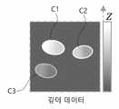
FIG. 7 shows an example of depth data obtained for the stereo image of FIG. 2 .
8 shows an apparatus for generating a deep depth image according to an embodiment of the present invention.
9 shows an example of a cell region segmentation image, region data, and depth data obtained from a stereo image according to an embodiment of the present invention.
10 shows an example of a high-depth image obtained from a stereo image, area data, and depth data according to an embodiment of the present invention.
이하에서는 도면을 참조하여 본 발명의 바람직한 실시예들을 상세히 설명한다. 이하 설명 및 첨부된 도면들에서 실질적으로 동일한 구성요소들은 각각 동일한 부호들로 나타냄으로써 중복 설명을 생략하기로 한다. 또한 본 발명을 설명함에 있어 관련된 공지기능 혹은 구성에 대한 구체적인 설명이 본 발명의 요지를 불필요하게 흐릴 수 있다고 판단되는 경우 그에 대한 상세한 설명은 생략하기로 한다.Hereinafter, preferred embodiments of the present invention will be described in detail with reference to the drawings. Substantially the same elements in the following description and accompanying drawings are indicated by the same reference numerals, respectively, and redundant description will be omitted. In addition, in describing the present invention, if it is determined that a detailed description of a related known function or configuration may unnecessarily obscure the subject matter of the present invention, a detailed description thereof will be omitted.
본 출원의 발명자는, 스테레오 카메라를 통해 촬영된 스테레오 영상은 깊이 정보를 내재하고 있고, 깊이 정보는 초점과 밀접한 연관성이 있으므로, 스테레오 영상으로부터 딥러닝 모델을 통해 고심도 영상을 생성할 수 있을 것이라는 점에서 본 발명을 착안하였다. 본 발명의 실시예에서 스테레오 영상은 세포를 촬영한 영상으로 예를 들어 설명하나, 촬영 대상은 세포 등의 생체 조직 뿐만 아니라 조직, 물질, 제품 등 다양할 수 있음은 물론이다. 또한 이하의 설명에서 고심도 영상이란, 단일 촬영 영상보다 초점이 맞는 깊이의 범위가 넓은 영상으로, 예컨대 스테레오 영상을 구성하는 각 영상보다 초점이 맞는 깊이의 범위가 넓은 영상을 의미한다.The inventor of the present application, since the stereo image captured through the stereo camera has depth information, and the depth information is closely related to the focus, it will be possible to generate a high-depth image from the stereo image through a deep learning model. conceived of the present invention. In the embodiment of the present invention, a stereo image is described as an image of a cell, but it goes without saying that the object to be photographed may be diverse, such as tissue, material, and product, as well as biological tissues such as cells. Also, in the following description, a high-depth image means an image with a wider range of in-focus depths than a single captured image, for example, an image with a wider range of in-focus depths than each image constituting a stereo image.
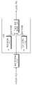
도 1은 본 발명의 일 실시예에 따른 고심도 영상 생성 모델 학습 장치를 나타낸다. 본 실시예에 따른 고심도 영상 생성 모델 학습 장치는, 스테레오 영상을 전처리하는 영상 전처리부(110), 스테레오 영상으로부터 고심도 영상을 출력하도록 구현된 학습 모델(120), 학습 데이터로 학습 모델(120)을 학습시키는 학습부(130)를 포함할 수 있다.1 shows an apparatus for learning a deep-depth image generation model according to an embodiment of the present invention. An apparatus for learning a deep image generation model according to the present embodiment includes an
학습 데이터는 스테레오 영상과 그에 대응하는 기준 고심도 영상의 데이터셋으로 이루어진다. 도 2는 스테레오 영상의 일 예를 설명하기 위한 도면이다. 스테레오 영상은 좌카메라 및 우카메라를 통해 각각 촬영된 좌영상 및 우영상을 포함할 수 있다. 도 2를 참조하면, 좌카메라와 우카메라는 서로 일정 각도 기울어진 다른 초점면(심도 범위)을 촬영하게 된다. 따라서 예컨대 3개의 세포 C1, C2, C3가 존재하는 경우, 좌영상에서는 세포 C2, C3만이 촬영되고, 우영상에서는 세포 C1, C2만이 촬영될 수 있다. 혹은, 동일한 세포가 한쪽 영상에서는 초점이 맞아 선명하게 나타나지만 다른쪽 영상에서는 초점이 맞지 않아 흐릿하게 나타날 수 있다.The learning data consists of a stereo image and a dataset of a reference high-depth image corresponding to the stereo image. 2 is a diagram for explaining an example of a stereo image. The stereo image may include a left image and a right image respectively photographed through a left camera and a right camera. Referring to FIG. 2 , the left camera and the right camera take pictures of different focal planes (depth ranges) tilted at a certain angle from each other. Accordingly, for example, when there are three cells C1, C2, and C3, only cells C2 and C3 can be captured in the left image, and only cells C1 and C2 can be captured in the right image. Alternatively, the same cell may appear in focus and clearly in one image, but may appear out of focus and blur in the other image.
좌카메라와 우카메라의 기울어진 각도는 목표로 하는 심도, 사용하려는 카메라 센서의 크기, 광학 배율 등을 고려하여 정해질 수 있다. 도 3a 및 3b는 각각 세포 병리와 조직 병리에서 카메라 각도를 정하는 것의 예를 설명하는 도면이다. 예를 들어, 22.5×16.9mm 크기의 카메라 센서를 사용하고 크롭 영상으로 외곽 왜곡 제거 후 20mm만 사용(w=20)하는 것으로 가정할 때, 40× 배율로 50um 두께 수준의 심도를 관찰하는 경우(m=40, d=0.05), 수학식

한편, 스테레오 영상은 서로 다른 광경로를 가지는 2이상의 카메라를 이용하여 획득될 수도 있으나, 하나의 광경로를 광 분할 수단(예컨대 빔스플리터, 프리즘, 거울 등)을 통해 2 이상의 광경로로 분할하여 다수의 카메라가 일정 각도 기울어진 초점면을 가지는 영상을 얻는 구조를 이용하여 획득될 수도 있다.Meanwhile, a stereo image may be acquired using two or more cameras having different optical paths, but a plurality of optical paths may be obtained by dividing one optical path into two or more optical paths through a light splitter (eg, a beam splitter, a prism, a mirror, etc.). It may be obtained by using a structure in which an image of a camera has a focal plane tilted at a certain angle.
도 4는 기준 고심도 영상의 일 예를 설명하기 위한 도면이다. 기준 고심도 영상은 해당 스테레오 영상의 동일 대상에 대하여 획득된 고심도 영상으로, 기존의 z-stack 기법을 이용하여 획득될 수 있다. 즉, 기준 고심도 영상은 해당 스테레오 영상과 동일한 (x, y) 오프셋 위치에서 z축의 초점면을 변경하면서 촬영된 다수의 영상을 합성하여 획득될 수 있다. 도 4를 참조하면, 기준 고심도 영상에서는 3개의 세포 C1, C2, C3가 모두 나타날 수 있다.4 is a diagram for explaining an example of a reference deep-depth image. The reference deep-depth image is a deep-depth image obtained for the same object of the corresponding stereo image, and may be obtained using a conventional z-stack technique. That is, the reference deep-depth image may be obtained by synthesizing a plurality of images captured while changing the focal plane of the z-axis at the same (x, y) offset position as the corresponding stereo image. Referring to FIG. 4 , all three cells C1, C2, and C3 may appear in the reference deep-depth image.
영상 전처리부(110)는 스테레오 영상에 대한 전처리로서 영상 증강(augmentation)과 영상 정규화(normalization)를 수행할 수 있다.The
영상 증강을 통해 학습 데이터를 늘려 노이즈에 대한 강건성을 확보하고 다양한 촬영 조건에 대해 모델이 학습되도록 할 수 있다. 영상 전처리부(110)는 영상의 밝기, 대비, RGB 값 등을 임의로 조정하여 학습 데이터의 양을 증대시킬 수 있다. 예컨대, 영상 전처리부(110)는 밝기, 대비, RGB 값 또는 그 분포를 평균, 표준편차에 따라 조정하거나, 비어-람베르트 법칙(Beer-Lambert Law of Light Absorption)에 따라 구한 감쇠 계수(Absorbance Coefficients)를 임의로 조정하여 염색(Staining)의 강도를 조정할 수 있다.Through image augmentation, training data can be increased to ensure robustness against noise and the model can be trained for various shooting conditions. The
영상 정규화를 통해 많은 학습 모델의 성능을 향상시키고 학습 수렴 속도를 높일 수 있다. 스테레오 영상의 학습 데이터는 일반적으로 여러 시점에 여러 장비를 통해 다양한 관찰 대상 세포를 촬영한 영상이므로, 촬영 조건이 다르기 마련이다. 또한 동일한 관찰 대상 세포라도 촬영 조건이나 증강을 통해 모사된 다양한 환경 변수에 의해 영상이 다르게 획득될 수 있다. 따라서 다양한 변이를 최소화하고 영상의 색공간을 맞추기 위해 영상 정규화가 수행될 수 있다. 예컨대 염색 정규화(staining normalization)는 비어-람베르트 법칙에 따른 H&E 염색의 광 감쇠 계수(Light Absorbance Coefficients)를 이용할 수 있다.Image normalization can improve the performance of many learning models and speed up training convergence. Since the learning data of the stereo image is generally an image obtained by photographing various cells to be observed through various equipment at various times, the shooting conditions are bound to be different. In addition, even in the same cell to be observed, images may be obtained differently depending on imaging conditions or various environmental variables simulated through augmentation. Therefore, image normalization may be performed to minimize various variations and match the color space of the image. For example, staining normalization may use Light Absorbance Coefficients of H&E staining according to Beer-Lambert's law.
실시예에 따라, 영상 증강과 영상 정규화는 모두 수행될 수도 있고, 학습 리소스의 제약에 따라 어느 하나만 수행되거나 모두 생략될 수도 있다.Depending on the embodiment, both image augmentation and image normalization may be performed, or only one may be performed or both may be omitted according to limitations of learning resources.
다시 도 1을 참조하면, 본 발명의 실시예에 따른 학습 모델(120)은, 입력되는 스테레오 영상에 대하여 세포 영역을 분할하여 영역 데이터를 생성하는 영역 분할부(121), 입력되는 스테레오 영상에 대하여 깊이를 추정하여 깊이 데이터를 생성하는 깊이 추정부(122), 및 입력되는 스테레오 영상, 영역 분할부(121)에서 출력되는 영역 데이터 및 깊이 추정부(122)에서 출력되는 깊이 데이터로부터 고심도 영상을 생성하는 고심도 영상 생성부(123)를 포함하도록 구축된다.Referring back to FIG. 1 , the
영역 분할부(121)는 좌영상 및 우영상 각각에 대하여 세포 영역을 분할하고, 세포 영역이 분할된 좌영상 및 우영상을 결합하여 영역 데이터를 생성할 수 있다. 영역 분할부(121)는 세포 영역을 분할할 때, 세포 영역과 그 외 영역을 전경과 배경으로 구분하는 한편 각 세포를 별개의 개체로 구분할 수 있다.The
세포 영역을 분할하는 과정은 예컨대 DeepLab v3, U-Net 등의 딥러닝 모델을 통해 수행될 수 있다. 딥러닝 모델을 사용하는 경우, 분할 속도가 빠르고 영상의 변이와 같은 다양한 촬영 조건에 대해 강건하고, 복잡한 영상에 대해 정확도가 높고, 목적에 따라 미세 조정(fine tuning)이 가능한 장점이 있다. 학습을 위한 리소스에 제약이 있는 경우, 세포 영역을 분할하는 과정은 Otsu Thresholding, Region Growing, Watershed algorithm, Graph cut, Active contour model, Active shape model 등과 같은 기존의 영역 분할 알고리즘을 이용하여 수행될 수도 있다.The process of segmenting the cell area may be performed through a deep learning model such as DeepLab v3 or U-Net. In the case of using a deep learning model, it has advantages such as fast segmentation speed, robustness to various shooting conditions such as image variation, high accuracy for complex images, and fine tuning according to the purpose. If there is a resource limitation for learning, the process of segmenting cell regions may be performed using existing region segmentation algorithms such as Otsu Thresholding, Region Growing, Watershed algorithm, Graph cut, Active contour model, Active shape model, etc. .
스테레오 영상을 구성하는 좌영상과 우영상은 심도가 낮아 두 영상에서 모든 세포가 동일하게 관찰되지 않을 수 있다. 따라서 서로 다른 깊이에 존재하는 세포들이 나타날 수 있도록 좌영상과 우영상이 결합될 수 있다. 좌영상과 우영상을 결합하는 과정에서, 딥러닝 모델을 통해 각 세포의 위치를 결합하고 자연스럽게 스티칭(stitching)할 수 있다. 도 5는 영역 데이터가 생성되는 과정을 설명하기 위한 도면이다. 스테레오 시차를 고려하더라도 동일 위치에서 좌, 우 영상이 서로 다른 경우, 전체 영상으로부터 추정한 배경색을 고려하여 좌, 우 영상으로부터 배경색과 거리가 먼 전경색이 선택될 수 있다. 배경색은 영상의 가장자리 영역에서 가장 많은 분포를 가지는 색으로 정해질 수 있다. 도 5에 도시된 바와 같이 영역 데이터는 배경 및 각 세포 영역을 구분하는 값을 가질 수 있다. 예컨대 도 5에 도시된 바와 같이, 배경에는 0, 각 세포 영역에는 1, 2, 3 등으로 서로 다른 픽셀값이 부여될 수 있다.The left image and the right image constituting the stereo image have a low depth of field, so not all cells may be observed identically in the two images. Therefore, the left image and the right image can be combined so that cells existing at different depths can be displayed. In the process of combining the left and right images, the location of each cell can be combined and stitched naturally through a deep learning model. 5 is a diagram for explaining a process of generating region data. Even if stereo parallax is considered, if the left and right images are different from each other at the same location, a foreground color distant from the background color of the left and right images may be selected in consideration of the background color estimated from the entire image. The background color may be determined as a color having the largest distribution in the edge area of the image. As shown in FIG. 5 , region data may have a background and values for classifying each cell region. For example, as shown in FIG. 5 , different pixel values such as 0 for the background and 1, 2, and 3 for each cell region may be assigned.
일반적으로 스테레오 영상은 두 영상의 시각차를 이용하여 대상체의 거리 또는 깊이를 추정함으로써 삼차원 영상을 생성하는 것을 목적으로 한다. 이에 비해 본 발명의 실시예에서는 스테레오 영상을 이용하여 영역 분할을 한다. 특히 고배율 영상에서는 초점 심도가 매우 낮아, 종종 단일 촬영 영역을 동시에 촬영한 스테레오 영상에 매우 다른 대상체가 촬영된다. 예를 들어 2개의 스테레오 영상을 분석할 때, 특정 세포가 2장의 영상 중 하나의 영상에서만 촬영되었을 경우, 일반적인 스테레오 깊이 추정 방식으로 처리할 경우 이 세포의 경우 매우 흐려지거나 영상에서 제외될 수 있다. 본 발명의 실시예에서는 2장의 스테레오 영상에서 각기 촬영된 대상체의 모양, 형태를 기준으로 세부 영역을 분할한다. 이때 2장의 스테레오 영상의 분할 위치가 일치하지 않는 대상체의 경우, 해당 영역에 대한 깊이 정보를 이용하여 최종 영상에서 영역 분할된 대상체를 명확하게 표현되도록 할 수 있다. 이를 통해 대물렌즈가 가지는 물리적 초점 심도 이상의 고심도 영상을 생성할 수 있으며 이때 심도의 깊이는 스테레오 영상이 가지는 시차각에 따라 결정된다.In general, a stereo image aims to generate a three-dimensional image by estimating a distance or depth of an object using a time difference between two images. In contrast, in the embodiment of the present invention, region segmentation is performed using a stereo image. In particular, in a high-magnification image, the depth of focus is very low, so very different objects are often captured in a stereo image in which a single imaging area is simultaneously captured. For example, when analyzing two stereo images, if a specific cell is captured in only one of the two images, this cell may be very blurred or excluded from the image when processed in a general stereo depth estimation method. In an embodiment of the present invention, detailed regions are divided based on the shape and shape of each imaged object in two stereo images. In this case, in the case of an object in which the division positions of the two stereo images do not match, the region-segmented object can be clearly expressed in the final image using depth information of the corresponding region. Through this, it is possible to generate a high-depth image that exceeds the physical focal depth of the objective lens, and at this time, the depth of the depth is determined according to the parallax angle of the stereo image.
일반적으로 고배율 영상에서는 최적의 초점을 위한 렌즈의 위치를 판단하기 위해 영상 분석을 수행하지만 본 발명의 실시예에서는 영상을 분석하는 방법 뿐 아니라 레이저 센서 등을 통해 조직 시편 슬라이드 높이(위치)를 측정하는 방식이 모두 가능하다. 레이저 센서 등을 통한 슬라이드 높이를 추정하는 방식은 정밀도가 렌즈 초점 심도에 비해 낮고 슬라이드의 높이를 파악하더라도 슬라이드 위에 시편의 두께 중 어느 높이(위치)에 세포가 있는지 알 수 없기 때문에 일반적인 고해상도 광학 촬영 시스템에서는 사용하지 않는 방식이다. 그러나 본 발명의 실시예의 경우 초점 심도를 시편의 두께와 유사한 두께까지 늘릴 수 있으므로 슬라이드 높이만 파악하면 최적화된 초점 영상을 확보할 수 있기 때문에, 기존에 생물학적으로 사용하기 어려웠던 레이저 센서를 렌즈 높이 조절 방식에 적용 가능하도록 하는 장점이 있다. 레이저 센서를 이용할 경우, 영상 분석을 통해 초점 높이 위치를 파악하는 방식에 비해 빠르게 초점 위치를 파악할 수 있어 촬영 속도를 높일 수 있는 이점이 있다. 또한 본 발명의 실시예의 경우 영상의 초점 심도가 렌즈의 초점 심도보다 길기 때문에 렌즈 초점 심도와 유사하거나 짧은 단위로 렌즈의 높이 위치를 조절하면서 영상의 초점 최적의 위치를 분석할 필요가 없다. 따라서 렌즈 초점 높이 조절을 위한 나노미터 수준의 초정밀 렌즈 위치 조절 기구물이 필요 없다.Generally, in high-magnification images, image analysis is performed to determine the position of the lens for optimal focus. All methods are possible. The method of estimating the slide height through a laser sensor is less accurate than the depth of focus of the lens, and even if the height of the slide is identified, it is not possible to know at which height (position) of the thickness of the specimen on the slide the cell is located. method not used in However, in the case of the embodiment of the present invention, since the depth of focus can be increased to a thickness similar to the thickness of the specimen, an optimized focus image can be obtained by identifying the slide height. It has the advantage of being applicable to In the case of using a laser sensor, there is an advantage in that the shooting speed can be increased because the focal position can be quickly identified compared to the method of determining the focal height position through image analysis. In addition, in the case of the embodiment of the present invention, since the depth of focus of the image is longer than the depth of focus of the lens, there is no need to analyze the optimal focal point of the image while adjusting the height of the lens in increments similar to or shorter than the depth of focus of the lens. Therefore, there is no need for an ultra-precise lens positioning mechanism at the nanometer level for adjusting the lens focal height.
깊이 추정부(122)는 좌영상 및 우영상 각각에 대하여 특징맵을 추출하고, 특징맵으로부터 세포의 크기 및 중심 위치 또는 관찰 위치를 통해 깊이를 추정할 수 있다. 영상의 중앙 부분은 물체(세포)가 동일하게 관찰되는 영역이 많은 반면, 영상의 외곽 부분에서는 깊이(z) 차이로 인해 동일하게 관찰되는 영역이 비교적 적다. 높은 심도를 위해 카메라 센서의 각도가 커질수록 이러한 현상이 더욱 커지며, 영상 분할 및 깊이 추정 성능에 영향을 미칠 수 있다. 따라서 물체(세포)를 구분하기 위해, 형태, 색깔, 중심 위치와 관찰 위치 등이 고려될 수 있다.좌영상 및 우영상으로부터 특징맵을 추출하는 과정은 VGG, ResNet, Inception 등의 합성곱신경망(Convolutional Neural Network, CNN) 모델을 통해 수행될 수 있다. 학습을 위한 리소스에 제약이 있는 경우, 특징맵은 기존의 스테레오 매칭 알고리즘을 이용하여 추출될 수도 있다.The
도 6은 세포의 크기 및 중심 위치와 관찰 위치를 통해 깊이가 추정되는 과정을 설명하기 위한 도면이다. 시차(disparity)에 따라 동일 세포가 좌, 우 영상에서 모두 관찰되는 경우 해당 세포의 범위(크기)와 중심 위치를 비교하여 깊이가 추정될 수 있다. 예컨대 세포 C2는 x축의 중앙으로부터 우측에서 관찰되고 좌영상보다 우영상에서 크기가 더 작고 중심이 치우치게 관찰되었으므로, 기준 초점(두 초점면이 교차하는 지점, 도 6 참조)보다 위(즉, 얕은 깊이)에 위치하는 것으로 추정할 수 있다. 좌, 우 영상 중 어느 한 영상에서만 세포가 관찰되는 경우, 해당 영상을 촬영한 카메라의 각도를 고려하여 깊이가 추정될 수 있다. 예컨대, 세포 C1은 우영상에서 관찰되었고 중심이 x축 중앙으로부터 왼쪽에 있으므로 기준 초점보다 위(즉, 얕은 깊이)에 위치하고, 세포 C3는 좌영상에서 관찰되었고 중심이 x축 중앙으로부터 왼쪽에 있으므로 기준 초점보다 아래(즉, 깊은 깊이)에 위치하는 것으로 추정할 수 있다. 이때 깊이값은 세포의 크기, 세포의 중심과 x축 중앙 간의 거리를 고려하여 추정될 수 있다. 다만 깊이값은 좌, 우 영상의 특징맵으로부터 DeepFocus 등의 CNN 모델을 통해 얻어질 수도 있다. 도 7은 도 2의 스테레오 영상에 대하여 얻어진 깊이 데이터의 일 예를 나타낸다. 예컨대 깊이 데이터는 배경은 0의 깊이값을, 세포 영역은 깊이에 따라 1~255의 깊이값을 가질 수 있다.6 is a diagram for explaining a process of estimating a depth through a cell size, center position, and observation position. When the same cell is observed in both the left and right images according to disparity, the depth can be estimated by comparing the range (size) of the corresponding cell and the center position. For example, since cell C2 was observed on the right side from the center of the x-axis and was smaller in size and biased in the right image than in the left image, it was above the reference focus (point where two focal planes intersect, see FIG. 6) (i.e., shallow depth). can be assumed to be located in When cells are observed in only one of the left and right images, the depth may be estimated by considering the angle of a camera that captures the corresponding image. For example, cell C1 was observed in the right image and is located above the reference focus (i.e., shallow depth) because its center is to the left of the center of the x-axis, and cell C3 was observed in the left image and is located to the left of the center of the x-axis, so it is located at the reference focus. It can be assumed to be located below (ie, at a great depth). In this case, the depth value may be estimated by considering the size of the cell and the distance between the center of the cell and the center of the x-axis. However, the depth value may be obtained through a CNN model such as DeepFocus from the feature maps of the left and right images. FIG. 7 shows an example of depth data obtained for the stereo image of FIG. 2 . For example, in the depth data, the background may have a depth value of 0, and the cell area may have a depth value of 1 to 255 depending on the depth.
영역 분할부(121)와 깊이 추정부(122)의 결과는 최종 고심도 영상을 생성하기 위해서 서로 그 결과에 영향을 미치며 영상의 수준을 높일 수 있다.The results of the
깊이 추정부(122)는 촬영 대상의 깊이를 추정함에 있어서 영역 분할부(121)를 통해 분할된 좌, 우 영상의 각 분할 영역에 대해서 독립적으로 깊이를 추정한 후 최종 깊이 데이터를 생성할 수 있다. 또한 각 영역별 깊이 추정 결과는 최종 생성될 고심도 영상의 영역 분할 결과에 영향을 미칠 수 있다. 도 6의 예시와 같이 좌영상과 우영상에서 동시에 촬영된 세포 C2의 경우, 좌, 우 영상은 세포 C2에 대해서 각기 다른 영역으로 분할할 것이고, 좌우 영상의 같은 위치에서 서로 다르게 분할된 영역에 대해서 어느 영역이 더욱 실제 세포의 크기를 반영할 것인가에 대한 판단은 다음과 같다. 깊이 추정부(122)는 좌, 우 영상의 영역 중 상대적으로 크고 대비가 뚜렷한 영상이 실제에 가까운 초점 높이에서 촬영되었다고 판단하여 대상체의 깊이를 추정하고, 해당 영상에서 분할 영역의 정보를 취할 수 있다. 따라서 최종 고심도 영상에서 세포 C2의 영역 범위는 좌영상에 나타나는 크기와 유사하게 생성될 수 있다.In estimating the depth of the object to be captured, the
다시 도 1을 참조하면, 고심도 영상 생성부(123)에 스테레오 영상, 영역 데이터, 깊이 데이터가 입력될 수 있다. 스테레오 영상이 RGB 영상인 경우, 좌영상 및 우영상 각각의 RGB 3채널, 영역 데이터 1채널, 깊이 데이터 1채널을 포함한 8채널의 데이터가 고심도 영상 생성부(123)에 입력될 수 있다. 고심도 영상 생성부(123)는 이러한 8채널의 입력 데이터로부터 딥러닝 모델을 통해 RGB 3채널의 고심도 영상을 생성할 수 있다.Referring back to FIG. 1 , a stereo image, region data, and depth data may be input to the deep depth image generator 123 . When the stereo image is an RGB image, data of 8 channels including 3 RGB channels for each of the left and right images, 1 channel of region data, and 1 channel of depth data may be input to the deep-depth image generator 123 . The deep-depth image generation unit 123 may generate a deep-depth image of 3 RGB channels from these 8-channel input data through a deep learning model.
고심도 영상 생성부(123)는 영역 데이터와 깊이 데이터 및 스테레오 영상으로부터 딥러닝 모델을 통해 스테레오 영상에 대하여 영역별로 깊이를 고려하여 디컨볼루션(deconvolution)을 수행할 수 있다. 상기 딥러닝 모델은 입력 데이터로부터 영상의 영역 또는 하위 영역의 초점 정도, 즉 인-포커스(in-focus) 또는 아웃-포커스(out-focus) 수준을 판단하고 학습된 해당 점 확산 함수를 적용하도록 구현될 수 있다. 점 확산 함수는 점 광원을 촬영했을 때 빛이 산란되는 모양을 함수로 나타낸 것으로, 점 확산 함수를 역으로 적용하면 흐릿한 영상으로부터 선명한 영상을 얻을 수 있다. 상기 딥러닝 모델은 CNN 모델로서, 점 확산 함수의 역함수를 추정하고 적용하는 블라인드 디컨볼루션(blind deconvolution)을 모사하도록 구현될 수 있다. 디컨볼루션 모델의 학습 성능 향상을 위해, 입력 데이터는 Jansson-Van Cittert algorithm, Agard's Modified algorithm, Regularized least squares minimization method, MLE(Maximum Likelihood Estimation), EM(Expectation Maximization) 등의 알고리즘을 통해 전처리될 수 있다.The deep-depth image generation unit 123 may perform deconvolution by considering depth for each region of the stereo image through a deep learning model from the region data, the depth data, and the stereo image. The deep learning model is implemented to determine the degree of focus of a region or sub-region of an image, that is, an in-focus or out-focus level from input data, and apply a corresponding learned point spread function. It can be. The point spread function is a function that expresses the scattering of light when a point light source is photographed. If the point spread function is applied inversely, a clear image can be obtained from a blurry image. The deep learning model is a CNN model, and may be implemented to simulate blind deconvolution that estimates and applies an inverse function of a point spread function. To improve the learning performance of deconvolution models, input data can be preprocessed through algorithms such as Jansson-Van Cittert algorithm, Agard's Modified algorithm, Regularized least squares minimization method, Maximum Likelihood Estimation (MLE), and Expectation Maximization (EM). there is.
학습부(130)는 스테레오 영상과 그에 대응하는 기준 고심도 영상을 포함하는 학습 데이터로 학습 모델(120)을 학습시킨다. 이때 학습부(130)는 학습 모델(120)을 종단간(End-to-End) 학습으로 학습시킬 수 있다.The learning unit 130 trains the
학습부(130)는 고심도 영상 생성부(123)로부터 출력되는 고심도 영상과 기준 고심도 영상으로부터 비용함수(cost function)를 계산하고, 비용함수를 이용하여 학습 모델(120)의 파라미터(가중치)를 갱신할 수 있다. 학습 모델(120)을 구성하는 영역 분할부(121), 깊이 추정부(122), 고심도 영상 생성부(123) 모두가 딥러닝 모델로 구현되는 경우, 학습 과정을 통해 이들 모두의 파라미터가 업데이트될 수 있고, 이 중 일부가 딥러닝 모델로 구현되는 경우 해당 딥러닝 모델의 파라미터가 업데이트될 수 있다. 비용함수는 Residual(출력 고심도 영상과 기준 고심도 영상 간의 차이), PSNR(Peak Signal-to-noise ratio), MSE(Mean Squared Error), SSIM(Structural Similarity), Perceptual Loss 등과 같은 손실함수의 합 또는 가중치합으로 구성될 수 있다. Residual, PSNR, MSE는 출력 고심도 영상과 기준 고심도 영상 간의 절대적인 오차를 줄이기 위해 사용될 수 있다. SSIM은 휘도, 대비 등 구조적인 특징을 반영하여 학습 성능을 향상시키기 위해 사용될 수 있다. Perceptual Loss는 세밀한 부분과 사람이 인지하는 특성에 대한 학습 성능을 향상시키기 위해 사용될 수 있다. 영역 분할부(121)의 성능 향상을 위해, 손실함수로 Segmentation Loss가 추가적으로 사용될 수도 있다. Segmentation Loss는 영역 분할부(121)에서 출력되는 영역 데이터와 기준 고심도 영상의 영역 분할 레이블을 비교하는 Dice Coefficient 수식을 사용할 수 있다.The learner 130 calculates a cost function from the deep image output from the deep image generator 123 and the reference deep image, and uses the cost function to calculate the parameters (weights) of the learning model 120. ) can be updated. When all of the
학습부(130)는 오류 역전파 기법(error back propagation method)을 이용하여 학습 모델(120)의 파라미터를 업데이트할 수 있다. 역전파 값은 최적화 알고리즘을 통해 조정될 수 있다. 예컨대 이전 상태(역전파 값과 방향 등)를 바탕으로 탐색 방향, 학습 강도(learning rate), 감쇠(decay), 모멘텀 등이 조정될 수 있다. 이를 통해, 학습 방향이 노이즈에 강건하도록 그리고 속도가 빨라지도록 최적화될 수 있다. 최적화 알고리즘으로 Adam Optimizer, SGD(Stochastic Gradient Descent), AdaGrad, RMSProp 등이 사용될 수 있다. 또한, 학습의 속도와 강건성 향상을 위해 배치 정규화(Batch Normalization)가 사용될 수 있다.The learning unit 130 may update parameters of the
학습부(130)는 학습 과정을 통해 비용함수의 값이 일정 수준 아래로 줄어들거나 설정된 에포크(epoch)에 도달할 때까지 학습 모델(120)을 학습시킬 수 있다.The learning unit 130 may train the
도 8은 본 발명의 일 실시예에 따른 고심도 영상 생성 장치를 나타낸다. 본 실시예에 따른 고심도 영상 생성 장치는, 스테레오 영상을 전처리하는 영상 전처리부(110') 및 전술한 고심도 영상 생성 모델 학습 장치를 통해, 스테레오 영상으로부터 고심도 영상을 출력하도록 학습된 학습 모델(120)을 포함할 수 있다.8 shows an apparatus for generating a deep depth image according to an embodiment of the present invention. In the deep-depth image generating apparatus according to the present embodiment, a learning model learned to output a deep-depth image from a stereo image through the
영상 전처리부(110')는 스테레오 영상에 대한 전처리로서 영상 정규화(normalization)를 수행할 수 있다. 영상 정규화는 도 1의 영상 전처리부(110)가 수행하는 영상 정규화와 동일할 수 있다.The image pre-processing unit 110' may perform image normalization as pre-processing of the stereo image. Image normalization may be the same as image normalization performed by the
학습 모델(120)은 입력되는 스테레오 영상에 대하여 세포 영역을 분할하여 영역 데이터를 생성하는 영역 분할부(121), 입력되는 스테레오 영상에 대하여 깊이를 추정하여 깊이 데이터를 생성하는 깊이 추정부(122), 및 입력되는 스테레오 영상, 영역 분할부(121)에서 출력되는 영역 데이터 및 깊이 추정부(122)에서 출력되는 깊이 데이터로부터 고심도 영상을 생성하는 고심도 영상 생성부(123)를 포함할 수 있다. 고심도 영상 생성부(123)는 전술한 고심도 영상 생성 모델 학습 장치를 통해 학습된 딥러닝 모델로 구현될 수 있다. 영역 분할부(121) 또는 깊이 추정부(122) 역시 전술한 고심도 영상 생성 모델 학습 장치를 통해 학습된 딥러닝 모델로 구현될 수 있다.The
도 9는 본 발명의 실시예에 따라 스테레오 영상으로부터 얻어지는 세포 영역 분할 영상, 영역 데이터 및 깊이 데이터의 예를 보여준다. 도 9를 참조하면, 좌영상(a1)에서 세포 영역이 분할된 영상(b1) 및 우영상(a2)에서 세포 영역이 분할된 영상(b2)이 결합되어 얻어진 영역 데이터(c)와, 좌영상(a1) 및 우영상(a2)으로부터 생성된 깊이 데이터(d)가 도시된다.9 shows an example of a cell region segmentation image, region data, and depth data obtained from a stereo image according to an embodiment of the present invention. Referring to FIG. 9 , region data (c) obtained by combining an image (b1) obtained by dividing a cell region from a left image (a1) and an image (b2) obtained by dividing a cell region from a right image (a2), and Depth data (d) generated from (a1) and right image (a2) is shown.
도 10은 본 발명의 실시예에 따라 스테레오 영상, 영역 데이터 및 깊이 데이터로부터 얻어지는 고심도 영상의 예를 보여준다. 도 10을 참조하면, 좌영상(3채널), 우영상(3채널), 영역 데이터(1채널), 및 깊이 데이터(1채널)가 고심도 영상 생성부(123)에 입력되면, 고심도 영상 생성부(123)는 딥러닝 모델을 통해 고심도 영상(3채널)을 출력한다.10 shows an example of a high-depth image obtained from a stereo image, area data, and depth data according to an embodiment of the present invention. Referring to FIG. 10 , when a left image (3 channels), a right image (3 channels), area data (1 channel), and depth data (1 channel) are input to the deep-depth image generator 123, the deep-depth image The generation unit 123 outputs a high-depth image (3 channels) through a deep learning model.
본 발명의 실시예들에 따른 장치는 프로세서, 프로그램 데이터를 저장하고 실행하는 메모리, 디스크 드라이브와 같은 영구 저장부(permanent storage), 외부 장치와 통신하는 통신 포트, 터치 패널, 키(key), 버튼 등과 같은 사용자 인터페이스 장치 등을 포함할 수 있다. 소프트웨어 모듈 또는 알고리즘으로 구현되는 방법들은 상기 프로세서상에서 실행 가능한 컴퓨터가 읽을 수 있는 코드들 또는 프로그램 명령들로서 컴퓨터가 읽을 수 있는 기록 매체 상에 저장될 수 있다. 여기서 컴퓨터가 읽을 수 있는 기록 매체로 마그네틱 저장 매체(예컨대, ROM(read-only memory), RAM(random-access memory), 플로피 디스크, 하드 디스크 등) 및 광학적 판독 매체(예컨대, 시디롬(CD-ROM), 디브이디(DVD: Digital Versatile Disc)) 등이 있다. 컴퓨터가 읽을 수 있는 기록 매체는 네트워크로 연결된 컴퓨터 시스템들에 분산되어, 분산 방식으로 컴퓨터가 판독 가능한 코드가 저장되고 실행될 수 있다. 매체는 컴퓨터에 의해 판독가능하며, 메모리에 저장되고, 프로세서에서 실행될 수 있다.Devices according to embodiments of the present invention include a processor, a memory for storing and executing program data, a permanent storage unit such as a disk drive, a communication port for communicating with an external device, a touch panel, a key, and a button. It may include user interface devices such as the like. Methods implemented as software modules or algorithms may be stored on a computer-readable recording medium as computer-readable codes or program instructions executable on the processor. Here, the computer-readable recording medium includes magnetic storage media (e.g., read-only memory (ROM), random-access memory (RAM), floppy disk, hard disk, etc.) and optical reading media (e.g., CD-ROM) ), and DVD (Digital Versatile Disc). A computer-readable recording medium may be distributed among computer systems connected through a network, and computer-readable codes may be stored and executed in a distributed manner. The medium may be readable by a computer, stored in a memory, and executed by a processor.
본 발명의 실시예들은 기능적인 블록 구성들 및 다양한 처리 단계들로 나타내어질 수 있다. 이러한 기능 블록들은 특정 기능들을 실행하는 다양한 개수의 하드웨어 또는/및 소프트웨어 구성들로 구현될 수 있다. 예를 들어, 실시예는 하나 이상의 마이크로프로세서들의 제어 또는 다른 제어 장치들에 의해서 다양한 기능들을 실행할 수 있는, 메모리, 프로세싱, 로직(logic), 룩 업 테이블(look-up table) 등과 같은 집적 회로 구성들을 채용할 수 있다. 본 발명에의 구성 요소들이 소프트웨어 프로그래밍 또는 소프트웨어 요소들로 실행될 수 있는 것과 유사하게, 실시예는 데이터 구조, 프로세스들, 루틴들 또는 다른 프로그래밍 구성들의 조합으로 구현되는 다양한 알고리즘을 포함하여, C, C++, 자바(Java), 어셈블러(assembler) 등과 같은 프로그래밍 또는 스크립팅 언어로 구현될 수 있다. 기능적인 측면들은 하나 이상의 프로세서들에서 실행되는 알고리즘으로 구현될 수 있다. 또한, 실시예는 전자적인 환경 설정, 신호 처리, 및/또는 데이터 처리 등을 위하여 종래 기술을 채용할 수 있다. "매커니즘", "요소", "수단", "구성"과 같은 용어는 넓게 사용될 수 있으며, 기계적이고 물리적인 구성들로서 한정되는 것은 아니다. 상기 용어는 프로세서 등과 연계하여 소프트웨어의 일련의 처리들(routines)의 의미를 포함할 수 있다.Embodiments of the invention may be presented as functional block structures and various processing steps. These functional blocks may be implemented with any number of hardware or/and software components that perform specific functions. For example, an embodiment may include an integrated circuit configuration, such as memory, processing, logic, look-up tables, etc., capable of executing various functions by means of the control of one or more microprocessors or other control devices. can employ them. Similar to components of the present invention that may be implemented as software programming or software elements, embodiments may include various algorithms implemented as data structures, processes, routines, or combinations of other programming constructs, such as C, C++ , Java (Java), can be implemented in a programming or scripting language such as assembler (assembler). Functional aspects may be implemented in an algorithm running on one or more processors. In addition, the embodiment may employ conventional techniques for electronic environment setting, signal processing, and/or data processing. Terms such as "mechanism", "element", "means", and "composition" may be used broadly and are not limited to mechanical and physical components. The term may include a meaning of a series of software routines in association with a processor or the like.
실시예에서 설명하는 특정 실행들은 일 실시예들로서, 어떠한 방법으로도 실시 예의 범위를 한정하는 것은 아니다. 명세서의 간결함을 위하여, 종래 전자적인 구성들, 제어 시스템들, 소프트웨어, 상기 시스템들의 다른 기능적인 측면들의 기재는 생략될 수 있다. 또한, 도면에 도시된 구성 요소들 간의 선들의 연결 또는 연결 부재들은 기능적인 연결 및/또는 물리적 또는 회로적 연결들을 예시적으로 나타낸 것으로서, 실제 장치에서는 대체 가능하거나 추가의 다양한 기능적인 연결, 물리적인 연결, 또는 회로 연결들로서 나타내어질 수 있다. 또한, "필수적인", "중요하게" 등과 같이 구체적인 언급이 없다면 본 발명의 적용을 위하여 반드시 필요한 구성 요소가 아닐 수 있다.Specific executions described in the embodiments are examples, and do not limit the scope of the embodiments in any way. For brevity of the specification, description of conventional electronic components, control systems, software, and other functional aspects of the systems may be omitted. In addition, the connection of lines or connecting members between the components shown in the drawings are examples of functional connections and / or physical or circuit connections, which can be replaced in actual devices or additional various functional connections, physical connection, or circuit connections. In addition, if there is no specific reference such as "essential" or "important", it may not necessarily be a component necessary for the application of the present invention.
이제까지 본 발명에 대하여 그 바람직한 실시예들을 중심으로 살펴보았다. 본 발명이 속하는 기술 분야에서 통상의 지식을 가진 자는 본 발명이 본 발명의 본질적인 특성에서 벗어나지 않는 범위에서 변형된 형태로 구현될 수 있음을 이해할 수 있을 것이다. 그러므로 개시된 실시예들은 한정적인 관점이 아니라 설명적인 관점에서 고려되어야 한다. 본 발명의 범위는 전술한 설명이 아니라 특허청구범위에 나타나 있으며, 그와 동등한 범위 내에 있는 모든 차이점은 본 발명에 포함된 것으로 해석되어야 할 것이다.So far, the present invention has been looked at with respect to its preferred embodiments. Those skilled in the art to which the present invention pertains will be able to understand that the present invention can be implemented in a modified form without departing from the essential characteristics of the present invention. Therefore, the disclosed embodiments should be considered from an illustrative rather than a limiting point of view. The scope of the present invention is shown in the claims rather than the foregoing description, and all differences within the equivalent scope will be construed as being included in the present invention.
Claims (20)
Translated fromKorean상기 스테레오 영상에 대하여 깊이를 추정하여 깊이 데이터를 생성하는 깊이 추정부; 및
상기 스테레오 영상, 상기 영역 데이터, 및 상기 깊이 데이터로부터 고심도 영상을 생성하는 고심도 영상 생성부를 포함하는 고심도 영상 생성 장치.a region dividing unit generating region data by dividing regions of the stereo image;
a depth estimation unit generating depth data by estimating a depth of the stereo image; and
and a deep-depth image generator configured to generate a deep-depth image from the stereo image, the region data, and the depth data.
상기 고심도 영상 생성부는 학습된 딥러닝 모델을 이용하여 상기 고심도 영상을 생성하는 고심도 영상 생성 장치.According to claim 1,
The deep-depth image generating unit generates the deep-depth image using the learned deep learning model.
상기 영역 분할부 또는 상기 깊이 추정부는 학습된 딥러닝 모델을 이용하여 상기 영역 데이터 또는 상기 깊이 데이터를 생성하는 고심도 영상 생성 장치.According to claim 2,
The region segmentation unit or the depth estimation unit generates the region data or the depth data using a learned deep learning model.
상기 영역 분할부는 상기 스테레오 영상을 구성하는 각 영상 별로 영역을 분할하여 영역 데이터를 생성하고,
상기 깊이 추정부는 분할된 각 영역 별로 깊이 데이터를 생성하는 고심도 영상 생성 장치.According to claim 1,
The region divider generates region data by dividing regions for each image constituting the stereo image;
The depth estimation unit generates depth data for each divided region.
상기 스테레오 영상은 조직 또는 세포를 촬영한 영상인 고심도 영상 생성 장치.According to claim 1,
The stereo image is a high-depth image generating device that is an image of a tissue or cell.
상기 학습된 딥러닝 모델은 점 확산 함수(Point-Spread Function)를 이용한 블라인드 디컨볼루션(blind deconvolution)을 모사하도록 구현된 고심도 영상 생성 장치.According to claim 2,
The deep learning model is implemented to simulate blind deconvolution using a point-spread function.
상기 스테레오 영상에 대하여 깊이를 추정하여 깊이 데이터를 생성하는 깊이 추정 과정; 및
상기 스테레오 영상, 상기 영역 데이터, 및 상기 깊이 데이터로부터 고심도 영상을 생성하는 고심도 영상 생성 과정을 포함하는 고심도 영상 생성 방법.a region dividing process of generating region data by dividing regions of the stereo image;
a depth estimation process of generating depth data by estimating a depth of the stereo image; and
and a deep-depth image generating process of generating a deep-depth image from the stereo image, the area data, and the depth data.
상기 고심도 영상 생성 과정은 학습된 딥러닝 모델을 이용하는 고심도 영상 생성 방법.According to claim 7,
The deep-depth image generation process is a deep-depth image generation method using a learned deep learning model.
상기 영역 분할 과정 또는 상기 깊이 추정 과정은 학습된 딥러닝 모델을 이용하는 고심도 영상 생성 방법.According to claim 8,
The region segmentation process or the depth estimation process is a deep-depth image generation method using a learned deep learning model.
상기 영역 분할부는 상기 스테레오 영상을 구성하는 각 영상 별로 영역을 분할하여 영역 데이터를 생성하고,
상기 깊이 추정부는 분할된 각 영역 별로 깊이 데이터를 생성하는 고심도 영상 생성 방법.According to claim 7,
The region divider generates region data by dividing regions for each image constituting the stereo image;
The depth estimation unit generates depth data for each divided region.
상기 스테레오 영상은 조직 또는 세포를 촬영한 영상인 고심도 영상 생성 방법.According to claim 7,
The stereo image is a high-depth image generation method in which a tissue or cell is photographed.
상기 학습된 딥러닝 모델은 점 확산 함수(Point-Spread Function)를 이용한 블라인드 디컨볼루션(blind deconvolution)을 모사하도록 구현된 고심도 영상 생성 방법.According to claim 8,
The deep learning model is implemented to simulate blind deconvolution using a point-spread function.
스테레오 영상과 그에 대응하는 기준 고심도 영상을 포함하는 학습 데이터로 상기 학습 모델을 학습시키는 학습부를 포함하는 고심도 영상 생성 모델 학습 장치.A learning model implemented to output a high-depth image from an input stereo image, a region dividing unit generating region data by dividing a region of the stereo image, and a depth generating depth data by estimating a depth of the stereo image. a learning model including an estimator and a deep-depth image generator generating a deep-depth image from the stereo image, the area data, and the depth data; and
A deep image generation model learning apparatus comprising a learning unit for learning the learning model with learning data including a stereo image and a reference deep image corresponding thereto.
상기 학습부는, 상기 학습 모델로부터 출력되는 고심도 영상과 상기 기준 고심도 영상으로부터 비용함수를 계산하고 상기 비용함수를 이용하여 상기 학습 모델을 학습시키는 고심도 영상 생성 모델 학습 장치.According to claim 13,
The learning unit calculates a cost function from the high depth image output from the learning model and the reference high depth image, and learns the learning model using the cost function.
상기 고심도 영상 생성부는 딥러닝 모델을 이용하여 상기 고심도 영상을 생성하는 고심도 영상 생성 모델 학습 장치.According to claim 13,
The deep-depth image generating unit generates the deep-depth image using a deep learning model.
상기 영역 분할부 또는 상기 깊이 추정부는 딥러닝 모델을 이용하여 상기 영역 데이터 또는 상기 깊이 데이터를 생성하는 고심도 영상 생성 모델 학습 장치.According to claim 15,
The region dividing unit or the depth estimation unit generates the region data or the depth data using a deep learning model.
상기 영역 분할부는 상기 스테레오 영상을 구성하는 각 영상 별로 영역을 분할하여 영역 데이터를 생성하고,
상기 깊이 추정부는 분할된 각 영역 별로 깊이 데이터를 생성하는 고심도 영상 생성 모델 학습 장치.According to claim 13,
The region divider generates region data by dividing regions for each image constituting the stereo image;
The depth estimation unit generates depth data for each divided region.
상기 스테레오 영상은 조직 또는 세포를 촬영한 영상인 고심도 영상 생성 모델 학습 장치.According to claim 13,
The stereo image is a high-depth image generation model learning device in which a tissue or cell is photographed.
상기 딥러닝 모델은 점 확산 함수(Point-Spread Function)를 이용한 블라인드 디컨볼루션(blind deconvolution)을 모사하도록 구현된 고심도 영상 생성 모델 학습 장치.According to claim 15,
The deep learning model is a deep image generation model learning device implemented to simulate blind deconvolution using a point-spread function.
상기 스테레오 영상을 전처리하여 상기 학습 모델에 입력하는 영상 전처리부를 더 포함하는 고심도 영상 생성 모델 학습 장치.According to claim 13,
The high-depth image generation model learning apparatus further comprises an image pre-processing unit for pre-processing the stereo image and inputting it to the learning model.
Priority Applications (4)
| Application Number | Priority Date | Filing Date | Title |
|---|---|---|---|
| KR1020210086859AKR102717662B1 (en) | 2021-07-02 | 2021-07-02 | Method and apparatus for generating high depth of field image, apparatus for training high depth of field image generation model using stereo image |
| JP2022107264AJP2023008998A (en) | 2021-07-02 | 2022-07-01 | Method and apparatus for generating high depth-of-field image and apparatus for training high depth-of-field image generation model using stereo image |
| EP22182608.4AEP4116926B1 (en) | 2021-07-02 | 2022-07-01 | Method and apparatus for generating high depth of field image, and apparatus for training high depth of field image generation model using stereo image |
| US17/856,847US12307676B2 (en) | 2021-07-02 | 2022-07-01 | Method and apparatus for generating high depth of field image, and apparatus for training high depth of field image generation model using stereo image |
Applications Claiming Priority (1)
| Application Number | Priority Date | Filing Date | Title |
|---|---|---|---|
| KR1020210086859AKR102717662B1 (en) | 2021-07-02 | 2021-07-02 | Method and apparatus for generating high depth of field image, apparatus for training high depth of field image generation model using stereo image |
Publications (2)
| Publication Number | Publication Date |
|---|---|
| KR20230006106Atrue KR20230006106A (en) | 2023-01-10 |
| KR102717662B1 KR102717662B1 (en) | 2024-10-15 |
Family
ID=82493972
Family Applications (1)
| Application Number | Title | Priority Date | Filing Date |
|---|---|---|---|
| KR1020210086859AActiveKR102717662B1 (en) | 2021-07-02 | 2021-07-02 | Method and apparatus for generating high depth of field image, apparatus for training high depth of field image generation model using stereo image |
Country Status (4)
| Country | Link |
|---|---|
| US (1) | US12307676B2 (en) |
| EP (1) | EP4116926B1 (en) |
| JP (1) | JP2023008998A (en) |
| KR (1) | KR102717662B1 (en) |
Cited By (1)
| Publication number | Priority date | Publication date | Assignee | Title |
|---|---|---|---|---|
| WO2025005389A1 (en)* | 2023-06-30 | 2025-01-02 | 국방과학연구소 | Fusion image generating method and apparatus, and storage medium storing instructions for performing fusion image generating method |
Families Citing this family (1)
| Publication number | Priority date | Publication date | Assignee | Title |
|---|---|---|---|---|
| WO2024191418A1 (en)* | 2023-03-14 | 2024-09-19 | Google Llc | Images with synthetic focus profiles generated from images from multiple perspectives |
Citations (5)
| Publication number | Priority date | Publication date | Assignee | Title |
|---|---|---|---|---|
| US20140354781A1 (en)* | 2013-05-28 | 2014-12-04 | Canon Kabushiki Kaisha | Image capture apparatus and control method thereof |
| US20150254811A1 (en)* | 2014-03-07 | 2015-09-10 | Qualcomm Incorporated | Depth aware enhancement for stereo video |
| JP2017199235A (en)* | 2016-04-28 | 2017-11-02 | 株式会社朋栄 | Focus correction processing method by learning type algorithm |
| US20190272638A1 (en)* | 2016-11-11 | 2019-09-05 | University Of South Florida | Automated Stereology for Determining Tissue Characteristics |
| US20200145642A1 (en)* | 2017-06-02 | 2020-05-07 | Shanghaitech University | Method and apparatus for estimating depth of field information |
Family Cites Families (10)
| Publication number | Priority date | Publication date | Assignee | Title |
|---|---|---|---|---|
| JP2016052116A (en) | 2014-08-28 | 2016-04-11 | パナソニックIpマネジメント株式会社 | Image processing device, image processing method and computer program |
| EP3459424A4 (en) | 2016-05-18 | 2020-01-22 | Mie University | CANCER TEST DEVICE, CANCER TEST METHOD AND COLORING AGENT FOR USE IN A CANCER TEST |
| US10387765B2 (en) | 2016-06-23 | 2019-08-20 | Siemens Healthcare Gmbh | Image correction using a deep generative machine-learning model |
| GB2553782B (en)* | 2016-09-12 | 2021-10-20 | Niantic Inc | Predicting depth from image data using a statistical model |
| JP7013578B2 (en)* | 2017-11-03 | 2022-01-31 | グーグル エルエルシー | Aperture monitoring for single-view depth prediction |
| KR101889886B1 (en) | 2017-12-22 | 2018-08-21 | 세명대학교 산학협력단 | Depth information generating method and apparatus |
| EP3797384A4 (en)* | 2018-05-22 | 2022-03-16 | Ramot at Tel-Aviv University Ltd. | METHOD AND SYSTEM FOR IMAGE GENERATION AND IMAGE PROCESSING |
| JP7234057B2 (en)* | 2018-08-24 | 2023-03-07 | キヤノン株式会社 | Image processing method, image processing device, imaging device, lens device, program, storage medium, and image processing system |
| US11195257B2 (en) | 2018-08-24 | 2021-12-07 | Canon Kabushiki Kaisha | Image processing method, image processing apparatus, imaging apparatus, lens apparatus, storage medium, and image processing system |
| KR102669255B1 (en) | 2019-02-01 | 2024-05-27 | 한국전자통신연구원 | Method and apparatus for generating all-in-focus image using multi-focus image |
- 2021
- 2021-07-02KRKR1020210086859Apatent/KR102717662B1/enactiveActive
- 2022
- 2022-07-01JPJP2022107264Apatent/JP2023008998A/enactivePending
- 2022-07-01EPEP22182608.4Apatent/EP4116926B1/enactiveActive
- 2022-07-01USUS17/856,847patent/US12307676B2/enactiveActive
Patent Citations (6)
| Publication number | Priority date | Publication date | Assignee | Title |
|---|---|---|---|---|
| US20140354781A1 (en)* | 2013-05-28 | 2014-12-04 | Canon Kabushiki Kaisha | Image capture apparatus and control method thereof |
| US20150254811A1 (en)* | 2014-03-07 | 2015-09-10 | Qualcomm Incorporated | Depth aware enhancement for stereo video |
| JP2017512440A (en)* | 2014-03-07 | 2017-05-18 | クアルコム,インコーポレイテッド | Improved depth recognition for stereo video |
| JP2017199235A (en)* | 2016-04-28 | 2017-11-02 | 株式会社朋栄 | Focus correction processing method by learning type algorithm |
| US20190272638A1 (en)* | 2016-11-11 | 2019-09-05 | University Of South Florida | Automated Stereology for Determining Tissue Characteristics |
| US20200145642A1 (en)* | 2017-06-02 | 2020-05-07 | Shanghaitech University | Method and apparatus for estimating depth of field information |
Non-Patent Citations (1)
| Title |
|---|
| Shajkofci, Adrian, and Michael Liebling. (2020). "Spatially-variant CNN-based point spread function estimation for blind deconvolution and depth estimation in optical microscopy." IEEE Transactions on** |
Cited By (2)
| Publication number | Priority date | Publication date | Assignee | Title |
|---|---|---|---|---|
| WO2025005389A1 (en)* | 2023-06-30 | 2025-01-02 | 국방과학연구소 | Fusion image generating method and apparatus, and storage medium storing instructions for performing fusion image generating method |
| KR20250002955A (en)* | 2023-06-30 | 2025-01-07 | 국방과학연구소 | Method and apparatus for generating fusion image |
Also Published As
| Publication number | Publication date |
|---|---|
| EP4116926B1 (en) | 2025-08-27 |
| EP4116926C0 (en) | 2025-08-27 |
| KR102717662B1 (en) | 2024-10-15 |
| US20230005155A1 (en) | 2023-01-05 |
| JP2023008998A (en) | 2023-01-19 |
| US12307676B2 (en) | 2025-05-20 |
| EP4116926A1 (en) | 2023-01-11 |
Similar Documents
| Publication | Publication Date | Title |
|---|---|---|
| Fuhl et al. | Fast camera focus estimation for gaze-based focus control | |
| KR101824936B1 (en) | Focus error estimation in images | |
| US20150256739A1 (en) | Fast Auto-Focus in Imaging | |
| KR102253320B1 (en) | Method for displaying 3 dimension image in integral imaging microscope system, and integral imaging microscope system implementing the same | |
| EP2786340A1 (en) | Image processing apparatus and image processing method | |
| US12307676B2 (en) | Method and apparatus for generating high depth of field image, and apparatus for training high depth of field image generation model using stereo image | |
| CN107038719A (en) | Depth estimation method and system based on light field image angle domain pixel | |
| AU2011357735A1 (en) | Fast auto-focus in microscopic imaging | |
| CN110352592A (en) | Imaging apparatus and imaging method, and image processing apparatus and image processing method | |
| EP4372672A1 (en) | Extended depth-of-field correction using reconstructed depth map | |
| JP6479666B2 (en) | Design method of passive single channel imager capable of estimating depth of field | |
| Florea et al. | Parametric logarithmic type image processing for contrast based auto-focus in extreme lighting conditions | |
| CN107209061B (en) | Method for determining complex amplitudes of scene-dependent electromagnetic fields | |
| CN119520771B (en) | Virtual training and evaluation method and device for intelligent focusing of surgical microscope | |
| CN108830804B (en) | Virtual-real fusion fuzzy consistency processing method based on line spread function standard deviation | |
| Shajkofci et al. | DeepFocus: a few-shot microscope slide auto-focus using a sample invariant CNN-based sharpness function | |
| EP4408007A1 (en) | Focal position estimation method, focal position estimation program, focal position estimation system, model generation method, model generation program, model generation system, and focal position estimation model | |
| KR100983548B1 (en) | A 3d shape reconstruction method considering point spread function of a microscope | |
| JP6949494B2 (en) | Image processing equipment and image processing methods, imaging equipment, programs | |
| Kriener et al. | Accelerating defocus blur magnification | |
| CN116263535A (en) | Method for determining z-stack boundaries of an image of an object | |
| Aslantas et al. | Multi focus image fusion by differential evolution algorithm | |
| Pertuz et al. | Focus-aided scene segmentation | |
| Averkin et al. | Using the method of depth reconstruction from focusing for microscope images | |
| US20250139799A1 (en) | Information processing apparatus, image capturing apparatus, method, and non-transitory computer readable storage medium |
Legal Events
| Date | Code | Title | Description |
|---|---|---|---|
| PA0109 | Patent application | Patent event code:PA01091R01D Comment text:Patent Application Patent event date:20210702 | |
| PA0201 | Request for examination | ||
| PG1501 | Laying open of application | ||
| E902 | Notification of reason for refusal | ||
| PE0902 | Notice of grounds for rejection | Comment text:Notification of reason for refusal Patent event date:20230816 Patent event code:PE09021S01D | |
| E90F | Notification of reason for final refusal | ||
| PE0902 | Notice of grounds for rejection | Comment text:Final Notice of Reason for Refusal Patent event date:20240131 Patent event code:PE09021S02D | |
| E701 | Decision to grant or registration of patent right | ||
| PE0701 | Decision of registration | Patent event code:PE07011S01D Comment text:Decision to Grant Registration Patent event date:20240925 | |
| GRNT | Written decision to grant | ||
| PR0701 | Registration of establishment | Comment text:Registration of Establishment Patent event date:20241010 Patent event code:PR07011E01D | |
| PR1002 | Payment of registration fee | Payment date:20241010 End annual number:3 Start annual number:1 | |
| PG1601 | Publication of registration |