KR20230000655A - Vehicle and control method thereof - Google Patents
Vehicle and control method thereofDownload PDFInfo
- Publication number
- KR20230000655A KR20230000655AKR1020210083025AKR20210083025AKR20230000655AKR 20230000655 AKR20230000655 AKR 20230000655AKR 1020210083025 AKR1020210083025 AKR 1020210083025AKR 20210083025 AKR20210083025 AKR 20210083025AKR 20230000655 AKR20230000655 AKR 20230000655A
- Authority
- KR
- South Korea
- Prior art keywords
- vehicle
- value
- information
- expected
- absolute coordinates
- Prior art date
- Legal status (The legal status is an assumption and is not a legal conclusion. Google has not performed a legal analysis and makes no representation as to the accuracy of the status listed.)
- Pending
Links
- 238000000034methodMethods0.000titleclaimsdescription24
- 230000033001locomotionEffects0.000claimsabstractdescription91
- 238000012545processingMethods0.000claimsabstractdescription6
- 230000008859changeEffects0.000claimsdescription20
- 238000004590computer programMethods0.000claimsdescription2
- 230000005540biological transmissionEffects0.000description12
- 230000001133accelerationEffects0.000description7
- 230000006854communicationEffects0.000description7
- 238000004891communicationMethods0.000description7
- 230000004044responseEffects0.000description7
- 230000006399behaviorEffects0.000description6
- 238000001514detection methodMethods0.000description6
- 230000008569processEffects0.000description6
- 238000010276constructionMethods0.000description5
- 230000004069differentiationEffects0.000description4
- 238000007726management methodMethods0.000description4
- 208000019901Anxiety diseaseDiseases0.000description3
- 230000036506anxietyEffects0.000description3
- 238000010586diagramMethods0.000description2
- 230000014509gene expressionEffects0.000description2
- 238000012935AveragingMethods0.000description1
- 230000007175bidirectional communicationEffects0.000description1
- 239000003086colorantSubstances0.000description1
- 238000013500data storageMethods0.000description1
- 230000006870functionEffects0.000description1
- 230000010354integrationEffects0.000description1
- 239000011159matrix materialSubstances0.000description1
- 230000003287optical effectEffects0.000description1
- 238000012546transferMethods0.000description1
Images


Classifications
- B—PERFORMING OPERATIONS; TRANSPORTING
- B60—VEHICLES IN GENERAL
- B60W—CONJOINT CONTROL OF VEHICLE SUB-UNITS OF DIFFERENT TYPE OR DIFFERENT FUNCTION; CONTROL SYSTEMS SPECIALLY ADAPTED FOR HYBRID VEHICLES; ROAD VEHICLE DRIVE CONTROL SYSTEMS FOR PURPOSES NOT RELATED TO THE CONTROL OF A PARTICULAR SUB-UNIT
- B60W30/00—Purposes of road vehicle drive control systems not related to the control of a particular sub-unit, e.g. of systems using conjoint control of vehicle sub-units
- B60W30/08—Active safety systems predicting or avoiding probable or impending collision or attempting to minimise its consequences
- B—PERFORMING OPERATIONS; TRANSPORTING
- B60—VEHICLES IN GENERAL
- B60W—CONJOINT CONTROL OF VEHICLE SUB-UNITS OF DIFFERENT TYPE OR DIFFERENT FUNCTION; CONTROL SYSTEMS SPECIALLY ADAPTED FOR HYBRID VEHICLES; ROAD VEHICLE DRIVE CONTROL SYSTEMS FOR PURPOSES NOT RELATED TO THE CONTROL OF A PARTICULAR SUB-UNIT
- B60W10/00—Conjoint control of vehicle sub-units of different type or different function
- B60W10/18—Conjoint control of vehicle sub-units of different type or different function including control of braking systems
- B—PERFORMING OPERATIONS; TRANSPORTING
- B60—VEHICLES IN GENERAL
- B60W—CONJOINT CONTROL OF VEHICLE SUB-UNITS OF DIFFERENT TYPE OR DIFFERENT FUNCTION; CONTROL SYSTEMS SPECIALLY ADAPTED FOR HYBRID VEHICLES; ROAD VEHICLE DRIVE CONTROL SYSTEMS FOR PURPOSES NOT RELATED TO THE CONTROL OF A PARTICULAR SUB-UNIT
- B60W10/00—Conjoint control of vehicle sub-units of different type or different function
- B60W10/20—Conjoint control of vehicle sub-units of different type or different function including control of steering systems
- B—PERFORMING OPERATIONS; TRANSPORTING
- B60—VEHICLES IN GENERAL
- B60W—CONJOINT CONTROL OF VEHICLE SUB-UNITS OF DIFFERENT TYPE OR DIFFERENT FUNCTION; CONTROL SYSTEMS SPECIALLY ADAPTED FOR HYBRID VEHICLES; ROAD VEHICLE DRIVE CONTROL SYSTEMS FOR PURPOSES NOT RELATED TO THE CONTROL OF A PARTICULAR SUB-UNIT
- B60W30/00—Purposes of road vehicle drive control systems not related to the control of a particular sub-unit, e.g. of systems using conjoint control of vehicle sub-units
- B60W30/08—Active safety systems predicting or avoiding probable or impending collision or attempting to minimise its consequences
- B60W30/09—Taking automatic action to avoid collision, e.g. braking and steering
- B—PERFORMING OPERATIONS; TRANSPORTING
- B60—VEHICLES IN GENERAL
- B60W—CONJOINT CONTROL OF VEHICLE SUB-UNITS OF DIFFERENT TYPE OR DIFFERENT FUNCTION; CONTROL SYSTEMS SPECIALLY ADAPTED FOR HYBRID VEHICLES; ROAD VEHICLE DRIVE CONTROL SYSTEMS FOR PURPOSES NOT RELATED TO THE CONTROL OF A PARTICULAR SUB-UNIT
- B60W30/00—Purposes of road vehicle drive control systems not related to the control of a particular sub-unit, e.g. of systems using conjoint control of vehicle sub-units
- B60W30/08—Active safety systems predicting or avoiding probable or impending collision or attempting to minimise its consequences
- B60W30/095—Predicting travel path or likelihood of collision
- B60W30/0953—Predicting travel path or likelihood of collision the prediction being responsive to vehicle dynamic parameters
- B—PERFORMING OPERATIONS; TRANSPORTING
- B60—VEHICLES IN GENERAL
- B60W—CONJOINT CONTROL OF VEHICLE SUB-UNITS OF DIFFERENT TYPE OR DIFFERENT FUNCTION; CONTROL SYSTEMS SPECIALLY ADAPTED FOR HYBRID VEHICLES; ROAD VEHICLE DRIVE CONTROL SYSTEMS FOR PURPOSES NOT RELATED TO THE CONTROL OF A PARTICULAR SUB-UNIT
- B60W30/00—Purposes of road vehicle drive control systems not related to the control of a particular sub-unit, e.g. of systems using conjoint control of vehicle sub-units
- B60W30/08—Active safety systems predicting or avoiding probable or impending collision or attempting to minimise its consequences
- B60W30/095—Predicting travel path or likelihood of collision
- B60W30/0956—Predicting travel path or likelihood of collision the prediction being responsive to traffic or environmental parameters
- B—PERFORMING OPERATIONS; TRANSPORTING
- B60—VEHICLES IN GENERAL
- B60W—CONJOINT CONTROL OF VEHICLE SUB-UNITS OF DIFFERENT TYPE OR DIFFERENT FUNCTION; CONTROL SYSTEMS SPECIALLY ADAPTED FOR HYBRID VEHICLES; ROAD VEHICLE DRIVE CONTROL SYSTEMS FOR PURPOSES NOT RELATED TO THE CONTROL OF A PARTICULAR SUB-UNIT
- B60W40/00—Estimation or calculation of non-directly measurable driving parameters for road vehicle drive control systems not related to the control of a particular sub unit, e.g. by using mathematical models
- B60W40/02—Estimation or calculation of non-directly measurable driving parameters for road vehicle drive control systems not related to the control of a particular sub unit, e.g. by using mathematical models related to ambient conditions
- B60W40/04—Traffic conditions
- B—PERFORMING OPERATIONS; TRANSPORTING
- B60—VEHICLES IN GENERAL
- B60W—CONJOINT CONTROL OF VEHICLE SUB-UNITS OF DIFFERENT TYPE OR DIFFERENT FUNCTION; CONTROL SYSTEMS SPECIALLY ADAPTED FOR HYBRID VEHICLES; ROAD VEHICLE DRIVE CONTROL SYSTEMS FOR PURPOSES NOT RELATED TO THE CONTROL OF A PARTICULAR SUB-UNIT
- B60W50/00—Details of control systems for road vehicle drive control not related to the control of a particular sub-unit, e.g. process diagnostic or vehicle driver interfaces
- B60W50/0098—Details of control systems ensuring comfort, safety or stability not otherwise provided for
- B—PERFORMING OPERATIONS; TRANSPORTING
- B60—VEHICLES IN GENERAL
- B60W—CONJOINT CONTROL OF VEHICLE SUB-UNITS OF DIFFERENT TYPE OR DIFFERENT FUNCTION; CONTROL SYSTEMS SPECIALLY ADAPTED FOR HYBRID VEHICLES; ROAD VEHICLE DRIVE CONTROL SYSTEMS FOR PURPOSES NOT RELATED TO THE CONTROL OF A PARTICULAR SUB-UNIT
- B60W50/00—Details of control systems for road vehicle drive control not related to the control of a particular sub-unit, e.g. process diagnostic or vehicle driver interfaces
- B60W50/08—Interaction between the driver and the control system
- B60W50/14—Means for informing the driver, warning the driver or prompting a driver intervention
- B60W50/16—Tactile feedback to the driver, e.g. vibration or force feedback to the driver on the steering wheel or the accelerator pedal
- B—PERFORMING OPERATIONS; TRANSPORTING
- B60—VEHICLES IN GENERAL
- B60W—CONJOINT CONTROL OF VEHICLE SUB-UNITS OF DIFFERENT TYPE OR DIFFERENT FUNCTION; CONTROL SYSTEMS SPECIALLY ADAPTED FOR HYBRID VEHICLES; ROAD VEHICLE DRIVE CONTROL SYSTEMS FOR PURPOSES NOT RELATED TO THE CONTROL OF A PARTICULAR SUB-UNIT
- B60W60/00—Drive control systems specially adapted for autonomous road vehicles
- B60W60/001—Planning or execution of driving tasks
- B60W60/0011—Planning or execution of driving tasks involving control alternatives for a single driving scenario, e.g. planning several paths to avoid obstacles
- B—PERFORMING OPERATIONS; TRANSPORTING
- B60—VEHICLES IN GENERAL
- B60W—CONJOINT CONTROL OF VEHICLE SUB-UNITS OF DIFFERENT TYPE OR DIFFERENT FUNCTION; CONTROL SYSTEMS SPECIALLY ADAPTED FOR HYBRID VEHICLES; ROAD VEHICLE DRIVE CONTROL SYSTEMS FOR PURPOSES NOT RELATED TO THE CONTROL OF A PARTICULAR SUB-UNIT
- B60W60/00—Drive control systems specially adapted for autonomous road vehicles
- B60W60/001—Planning or execution of driving tasks
- B60W60/0013—Planning or execution of driving tasks specially adapted for occupant comfort
- B—PERFORMING OPERATIONS; TRANSPORTING
- B60—VEHICLES IN GENERAL
- B60W—CONJOINT CONTROL OF VEHICLE SUB-UNITS OF DIFFERENT TYPE OR DIFFERENT FUNCTION; CONTROL SYSTEMS SPECIALLY ADAPTED FOR HYBRID VEHICLES; ROAD VEHICLE DRIVE CONTROL SYSTEMS FOR PURPOSES NOT RELATED TO THE CONTROL OF A PARTICULAR SUB-UNIT
- B60W50/00—Details of control systems for road vehicle drive control not related to the control of a particular sub-unit, e.g. process diagnostic or vehicle driver interfaces
- B60W2050/0001—Details of the control system
- B60W2050/0002—Automatic control, details of type of controller or control system architecture
- B60W2050/0004—In digital systems, e.g. discrete-time systems involving sampling
- B60W2050/0005—Processor details or data handling, e.g. memory registers or chip architecture
- B—PERFORMING OPERATIONS; TRANSPORTING
- B60—VEHICLES IN GENERAL
- B60W—CONJOINT CONTROL OF VEHICLE SUB-UNITS OF DIFFERENT TYPE OR DIFFERENT FUNCTION; CONTROL SYSTEMS SPECIALLY ADAPTED FOR HYBRID VEHICLES; ROAD VEHICLE DRIVE CONTROL SYSTEMS FOR PURPOSES NOT RELATED TO THE CONTROL OF A PARTICULAR SUB-UNIT
- B60W50/00—Details of control systems for road vehicle drive control not related to the control of a particular sub-unit, e.g. process diagnostic or vehicle driver interfaces
- B60W2050/0001—Details of the control system
- B60W2050/0043—Signal treatments, identification of variables or parameters, parameter estimation or state estimation
- B60W2050/0057—Frequency analysis, spectral techniques or transforms
- B—PERFORMING OPERATIONS; TRANSPORTING
- B60—VEHICLES IN GENERAL
- B60W—CONJOINT CONTROL OF VEHICLE SUB-UNITS OF DIFFERENT TYPE OR DIFFERENT FUNCTION; CONTROL SYSTEMS SPECIALLY ADAPTED FOR HYBRID VEHICLES; ROAD VEHICLE DRIVE CONTROL SYSTEMS FOR PURPOSES NOT RELATED TO THE CONTROL OF A PARTICULAR SUB-UNIT
- B60W50/00—Details of control systems for road vehicle drive control not related to the control of a particular sub-unit, e.g. process diagnostic or vehicle driver interfaces
- B60W50/08—Interaction between the driver and the control system
- B60W50/14—Means for informing the driver, warning the driver or prompting a driver intervention
- B60W2050/143—Alarm means
- B—PERFORMING OPERATIONS; TRANSPORTING
- B60—VEHICLES IN GENERAL
- B60W—CONJOINT CONTROL OF VEHICLE SUB-UNITS OF DIFFERENT TYPE OR DIFFERENT FUNCTION; CONTROL SYSTEMS SPECIALLY ADAPTED FOR HYBRID VEHICLES; ROAD VEHICLE DRIVE CONTROL SYSTEMS FOR PURPOSES NOT RELATED TO THE CONTROL OF A PARTICULAR SUB-UNIT
- B60W50/00—Details of control systems for road vehicle drive control not related to the control of a particular sub-unit, e.g. process diagnostic or vehicle driver interfaces
- B60W50/08—Interaction between the driver and the control system
- B60W50/14—Means for informing the driver, warning the driver or prompting a driver intervention
- B60W2050/146—Display means
- B—PERFORMING OPERATIONS; TRANSPORTING
- B60—VEHICLES IN GENERAL
- B60W—CONJOINT CONTROL OF VEHICLE SUB-UNITS OF DIFFERENT TYPE OR DIFFERENT FUNCTION; CONTROL SYSTEMS SPECIALLY ADAPTED FOR HYBRID VEHICLES; ROAD VEHICLE DRIVE CONTROL SYSTEMS FOR PURPOSES NOT RELATED TO THE CONTROL OF A PARTICULAR SUB-UNIT
- B60W2420/00—Indexing codes relating to the type of sensors based on the principle of their operation
- B60W2420/40—Photo, light or radio wave sensitive means, e.g. infrared sensors
- B60W2420/403—Image sensing, e.g. optical camera
- B—PERFORMING OPERATIONS; TRANSPORTING
- B60—VEHICLES IN GENERAL
- B60W—CONJOINT CONTROL OF VEHICLE SUB-UNITS OF DIFFERENT TYPE OR DIFFERENT FUNCTION; CONTROL SYSTEMS SPECIALLY ADAPTED FOR HYBRID VEHICLES; ROAD VEHICLE DRIVE CONTROL SYSTEMS FOR PURPOSES NOT RELATED TO THE CONTROL OF A PARTICULAR SUB-UNIT
- B60W2420/00—Indexing codes relating to the type of sensors based on the principle of their operation
- B60W2420/40—Photo, light or radio wave sensitive means, e.g. infrared sensors
- B60W2420/408—Radar; Laser, e.g. lidar
- B—PERFORMING OPERATIONS; TRANSPORTING
- B60—VEHICLES IN GENERAL
- B60W—CONJOINT CONTROL OF VEHICLE SUB-UNITS OF DIFFERENT TYPE OR DIFFERENT FUNCTION; CONTROL SYSTEMS SPECIALLY ADAPTED FOR HYBRID VEHICLES; ROAD VEHICLE DRIVE CONTROL SYSTEMS FOR PURPOSES NOT RELATED TO THE CONTROL OF A PARTICULAR SUB-UNIT
- B60W2520/00—Input parameters relating to overall vehicle dynamics
- B60W2520/06—Direction of travel
- B—PERFORMING OPERATIONS; TRANSPORTING
- B60—VEHICLES IN GENERAL
- B60W—CONJOINT CONTROL OF VEHICLE SUB-UNITS OF DIFFERENT TYPE OR DIFFERENT FUNCTION; CONTROL SYSTEMS SPECIALLY ADAPTED FOR HYBRID VEHICLES; ROAD VEHICLE DRIVE CONTROL SYSTEMS FOR PURPOSES NOT RELATED TO THE CONTROL OF A PARTICULAR SUB-UNIT
- B60W2520/00—Input parameters relating to overall vehicle dynamics
- B60W2520/10—Longitudinal speed
- B—PERFORMING OPERATIONS; TRANSPORTING
- B60—VEHICLES IN GENERAL
- B60W—CONJOINT CONTROL OF VEHICLE SUB-UNITS OF DIFFERENT TYPE OR DIFFERENT FUNCTION; CONTROL SYSTEMS SPECIALLY ADAPTED FOR HYBRID VEHICLES; ROAD VEHICLE DRIVE CONTROL SYSTEMS FOR PURPOSES NOT RELATED TO THE CONTROL OF A PARTICULAR SUB-UNIT
- B60W2554/00—Input parameters relating to objects
- B60W2554/40—Dynamic objects, e.g. animals, windblown objects
- B60W2554/402—Type
- B60W2554/4026—Cycles
- B—PERFORMING OPERATIONS; TRANSPORTING
- B60—VEHICLES IN GENERAL
- B60W—CONJOINT CONTROL OF VEHICLE SUB-UNITS OF DIFFERENT TYPE OR DIFFERENT FUNCTION; CONTROL SYSTEMS SPECIALLY ADAPTED FOR HYBRID VEHICLES; ROAD VEHICLE DRIVE CONTROL SYSTEMS FOR PURPOSES NOT RELATED TO THE CONTROL OF A PARTICULAR SUB-UNIT
- B60W2554/00—Input parameters relating to objects
- B60W2554/40—Dynamic objects, e.g. animals, windblown objects
- B60W2554/402—Type
- B60W2554/4029—Pedestrians
- B—PERFORMING OPERATIONS; TRANSPORTING
- B60—VEHICLES IN GENERAL
- B60W—CONJOINT CONTROL OF VEHICLE SUB-UNITS OF DIFFERENT TYPE OR DIFFERENT FUNCTION; CONTROL SYSTEMS SPECIALLY ADAPTED FOR HYBRID VEHICLES; ROAD VEHICLE DRIVE CONTROL SYSTEMS FOR PURPOSES NOT RELATED TO THE CONTROL OF A PARTICULAR SUB-UNIT
- B60W2554/00—Input parameters relating to objects
- B60W2554/40—Dynamic objects, e.g. animals, windblown objects
- B60W2554/404—Characteristics
- B60W2554/4041—Position
- B—PERFORMING OPERATIONS; TRANSPORTING
- B60—VEHICLES IN GENERAL
- B60W—CONJOINT CONTROL OF VEHICLE SUB-UNITS OF DIFFERENT TYPE OR DIFFERENT FUNCTION; CONTROL SYSTEMS SPECIALLY ADAPTED FOR HYBRID VEHICLES; ROAD VEHICLE DRIVE CONTROL SYSTEMS FOR PURPOSES NOT RELATED TO THE CONTROL OF A PARTICULAR SUB-UNIT
- B60W2554/00—Input parameters relating to objects
- B60W2554/40—Dynamic objects, e.g. animals, windblown objects
- B60W2554/404—Characteristics
- B60W2554/4042—Longitudinal speed
- B—PERFORMING OPERATIONS; TRANSPORTING
- B60—VEHICLES IN GENERAL
- B60W—CONJOINT CONTROL OF VEHICLE SUB-UNITS OF DIFFERENT TYPE OR DIFFERENT FUNCTION; CONTROL SYSTEMS SPECIALLY ADAPTED FOR HYBRID VEHICLES; ROAD VEHICLE DRIVE CONTROL SYSTEMS FOR PURPOSES NOT RELATED TO THE CONTROL OF A PARTICULAR SUB-UNIT
- B60W2554/00—Input parameters relating to objects
- B60W2554/40—Dynamic objects, e.g. animals, windblown objects
- B60W2554/404—Characteristics
- B60W2554/4043—Lateral speed
- B—PERFORMING OPERATIONS; TRANSPORTING
- B60—VEHICLES IN GENERAL
- B60W—CONJOINT CONTROL OF VEHICLE SUB-UNITS OF DIFFERENT TYPE OR DIFFERENT FUNCTION; CONTROL SYSTEMS SPECIALLY ADAPTED FOR HYBRID VEHICLES; ROAD VEHICLE DRIVE CONTROL SYSTEMS FOR PURPOSES NOT RELATED TO THE CONTROL OF A PARTICULAR SUB-UNIT
- B60W2554/00—Input parameters relating to objects
- B60W2554/40—Dynamic objects, e.g. animals, windblown objects
- B60W2554/404—Characteristics
- B60W2554/4044—Direction of movement, e.g. backwards
- B—PERFORMING OPERATIONS; TRANSPORTING
- B60—VEHICLES IN GENERAL
- B60W—CONJOINT CONTROL OF VEHICLE SUB-UNITS OF DIFFERENT TYPE OR DIFFERENT FUNCTION; CONTROL SYSTEMS SPECIALLY ADAPTED FOR HYBRID VEHICLES; ROAD VEHICLE DRIVE CONTROL SYSTEMS FOR PURPOSES NOT RELATED TO THE CONTROL OF A PARTICULAR SUB-UNIT
- B60W2554/00—Input parameters relating to objects
- B60W2554/40—Dynamic objects, e.g. animals, windblown objects
- B60W2554/404—Characteristics
- B60W2554/4045—Intention, e.g. lane change or imminent movement
- B—PERFORMING OPERATIONS; TRANSPORTING
- B60—VEHICLES IN GENERAL
- B60W—CONJOINT CONTROL OF VEHICLE SUB-UNITS OF DIFFERENT TYPE OR DIFFERENT FUNCTION; CONTROL SYSTEMS SPECIALLY ADAPTED FOR HYBRID VEHICLES; ROAD VEHICLE DRIVE CONTROL SYSTEMS FOR PURPOSES NOT RELATED TO THE CONTROL OF A PARTICULAR SUB-UNIT
- B60W2554/00—Input parameters relating to objects
- B60W2554/40—Dynamic objects, e.g. animals, windblown objects
- B60W2554/404—Characteristics
- B60W2554/4046—Behavior, e.g. aggressive or erratic
- B—PERFORMING OPERATIONS; TRANSPORTING
- B60—VEHICLES IN GENERAL
- B60W—CONJOINT CONTROL OF VEHICLE SUB-UNITS OF DIFFERENT TYPE OR DIFFERENT FUNCTION; CONTROL SYSTEMS SPECIALLY ADAPTED FOR HYBRID VEHICLES; ROAD VEHICLE DRIVE CONTROL SYSTEMS FOR PURPOSES NOT RELATED TO THE CONTROL OF A PARTICULAR SUB-UNIT
- B60W2554/00—Input parameters relating to objects
- B60W2554/40—Dynamic objects, e.g. animals, windblown objects
- B60W2554/406—Traffic density
- B—PERFORMING OPERATIONS; TRANSPORTING
- B60—VEHICLES IN GENERAL
- B60W—CONJOINT CONTROL OF VEHICLE SUB-UNITS OF DIFFERENT TYPE OR DIFFERENT FUNCTION; CONTROL SYSTEMS SPECIALLY ADAPTED FOR HYBRID VEHICLES; ROAD VEHICLE DRIVE CONTROL SYSTEMS FOR PURPOSES NOT RELATED TO THE CONTROL OF A PARTICULAR SUB-UNIT
- B60W2554/00—Input parameters relating to objects
- B60W2554/80—Spatial relation or speed relative to objects
- B60W2554/801—Lateral distance
- B—PERFORMING OPERATIONS; TRANSPORTING
- B60—VEHICLES IN GENERAL
- B60W—CONJOINT CONTROL OF VEHICLE SUB-UNITS OF DIFFERENT TYPE OR DIFFERENT FUNCTION; CONTROL SYSTEMS SPECIALLY ADAPTED FOR HYBRID VEHICLES; ROAD VEHICLE DRIVE CONTROL SYSTEMS FOR PURPOSES NOT RELATED TO THE CONTROL OF A PARTICULAR SUB-UNIT
- B60W2554/00—Input parameters relating to objects
- B60W2554/80—Spatial relation or speed relative to objects
- B60W2554/802—Longitudinal distance
- B—PERFORMING OPERATIONS; TRANSPORTING
- B60—VEHICLES IN GENERAL
- B60W—CONJOINT CONTROL OF VEHICLE SUB-UNITS OF DIFFERENT TYPE OR DIFFERENT FUNCTION; CONTROL SYSTEMS SPECIALLY ADAPTED FOR HYBRID VEHICLES; ROAD VEHICLE DRIVE CONTROL SYSTEMS FOR PURPOSES NOT RELATED TO THE CONTROL OF A PARTICULAR SUB-UNIT
- B60W2556/00—Input parameters relating to data
- B60W2556/10—Historical data
- B—PERFORMING OPERATIONS; TRANSPORTING
- B60—VEHICLES IN GENERAL
- B60W—CONJOINT CONTROL OF VEHICLE SUB-UNITS OF DIFFERENT TYPE OR DIFFERENT FUNCTION; CONTROL SYSTEMS SPECIALLY ADAPTED FOR HYBRID VEHICLES; ROAD VEHICLE DRIVE CONTROL SYSTEMS FOR PURPOSES NOT RELATED TO THE CONTROL OF A PARTICULAR SUB-UNIT
- B60W2556/00—Input parameters relating to data
- B60W2556/45—External transmission of data to or from the vehicle
- B60W2556/50—External transmission of data to or from the vehicle of positioning data, e.g. GPS [Global Positioning System] data
Landscapes
- Engineering & Computer Science (AREA)
- Automation & Control Theory (AREA)
- Transportation (AREA)
- Mechanical Engineering (AREA)
- Human Computer Interaction (AREA)
- Chemical & Material Sciences (AREA)
- Combustion & Propulsion (AREA)
- Physics & Mathematics (AREA)
- Mathematical Physics (AREA)
- Traffic Control Systems (AREA)
- Control Of Driving Devices And Active Controlling Of Vehicle (AREA)
Abstract
Translated fromKoreanDescription
Translated fromKorean개시된 발명은 차량 및 그 제어 방법에 관한 발명으로, 더욱 상세하게는 운전자 보조 시스템에 관한 것이다.The disclosed invention relates to a vehicle and a control method thereof, and more particularly, to a driver assistance system.
운전자 보조 시스템(Advanced Driver Assist System; ADAS)은 차량에 탑재된 카메라 및 레이더 등의 다양한 센서를 활용하여 보행자 또는 다른 차량과의 충돌 가능성을 판단하고, 이에 기초하여 제동 장치 또는 조향 장치를 자동으로 제어하여 충돌 사고를 미연에 회피하도록 한다.An Advanced Driver Assist System (ADAS) utilizes various sensors such as cameras and radars mounted on a vehicle to determine the possibility of collision with a pedestrian or other vehicle, and based on this, automatically controls the braking system or steering system. so as to avoid a collision accident.
운전자 보조 시스템은 선행적으로 다른 차량에 대한 충돌 가능성을 판단하는 것이 필요하며, 충돌 가능성은 다른 차량의 현재 위치 및 현재 속도에 기반하여 판단된다.The driver assistance system needs to determine the possibility of collision with another vehicle in advance, and the possibility of collision is determined based on the current location and current speed of the other vehicle.
그러나, 실제 도로는 유형 또는 상황이 각각이므로 상술한 일률적인 판단은 급작스러운 상황을 대비하지 못하거나, 긴급 제동으로 인한 불안감을 탑승자에게 제공할 수 있다.However, since actual roads have different types or situations, the above-described uniform judgment may not prepare for a sudden situation or may provide passengers with anxiety due to emergency braking.
개시된 발명의 일 측면은 위험 대상체를 선제적으로 파악하여 충돌을 미연에 방지하고, 자율 주행에 의한 탑승자의 불안감을 해소하기 위한 차량 및 그 제어 방법을 제공하기 위한 것이다.One aspect of the disclosed invention is to provide a vehicle and a control method thereof for preemptively identifying dangerous objects to prevent collisions and to relieve passengers' anxiety due to autonomous driving.
개시된 발명의 일 실시예에 따른 차량은 대상체의 운동 상태 정보인 제1 운동 정보를 획득하기 위한 센서; 차량의 위치 정보를 획득하기 위한 내비게이터; 및 상기 위치 정보 및 상기 제1 운동 정보를 처리하는 적어도 하나의 프로세서를 포함하는 제어부;를 포함하고, 상기 제어부는, 상기 위치 정보에 기초하여 상기 대상체의 운동 기대값을 수신하고, 상기 운동 기대값과 상기 제1 운동 정보를 비교하여 차이값을 산출하고, 상기 차이값이 미리 정해진 수치 이상이면 상기 대상체를 위험 대상체로 판단한다.A vehicle according to an embodiment of the present disclosure includes a sensor for obtaining first exercise information that is motion state information of an object; a navigator for acquiring vehicle location information; and a control unit including at least one processor to process the location information and the first exercise information, wherein the control unit receives an expected motion value of the object based on the location information, and the expected motion value A difference value is calculated by comparing the first exercise information and the first exercise information, and if the difference value is greater than or equal to a predetermined value, the object is determined as a risk object.
상기 제어부는, 상기 운동 기대값이 저장된 메모리 또는 서버로부터 상기 운동 기대값을 수신할 수 있다.The controller may receive the expected exercise value from a memory or a server in which the expected exercise value is stored.
상기 운동 기대값은, 상기 차량이 주행 중인 해당 지역을 통과한 복수의 다른 차량의 위치 및 속도가 누적된 데이터일 수 있다.The expected motion value may be data obtained by accumulating positions and speeds of a plurality of other vehicles that have passed through the region in which the vehicle is driving.
상기 제어부는, 상기 제1 운동 정보에 포함된 상대 거리를 상기 차량을 기준으로 하는 제1 절대 좌표로 변환하고, 상기 운동 기대값은 상기 차량을 기준으로 상기 복수의 다른 차량의 위치를 제2 절대 좌표로 변환된 것일 수 있다.The control unit converts the relative distance included in the first motion information into first absolute coordinates based on the vehicle, and the expected motion value determines the positions of the plurality of other vehicles based on the vehicle as second absolute coordinates. It may be converted to coordinates.
상기 제어부는, 상기 제1 절대 좌표와 상기 제2 절대 좌표를 비교하여 위치 차이값을 산출하고, 상기 위치 차이값이 미리 정해진 수치 이상이면 위험 대상체로 판단할 수 있다.The controller compares the first absolute coordinates with the second absolute coordinates to calculate a position difference value, and if the position difference value is equal to or greater than a predetermined value, it can be determined as a dangerous object.
상기 제어부는, 상기 제1 절대 좌표의 위치 별 속도와 상기 제2 절대 좌표 별 속도와 비교하여 속도 차이값을 산출하고, 상기 속도 차이값이 미리 정해진 수치 이상이면 상기 위험 대상체가 교통 체증을 유발하는 것으로 판단할 수 있다.The control unit calculates a speed difference value by comparing the speed for each position of the first absolute coordinates with the speed for each position of the second absolute coordinates, and if the speed difference value is equal to or greater than a predetermined value, the risk object causes traffic jam. can be judged to be
상기 제어부는, 상기 차량의 주행 방향인 제1 방향에 대한 상기 제1 절대 좌표의 위치 별 제1 속도 변화량과 상기 제2 절대 좌표의 위치 별 제2 속도 변화량 간의 차이가 미리 정해진 수치 이상이면 상기 위험 대상체가 급정거 차량인 것으로 판단할 수 있다.The control unit may determine the danger when the difference between the first speed variation per position of the first absolute coordinates and the second speed variation per position of the second absolute coordinates in the first direction, which is the driving direction of the vehicle, is greater than or equal to a predetermined value. It may be determined that the object is an emergency vehicle.
상기 제어부는, 상기 제1 방향과 수직인 제2 방향에 대한 상기 제1 절대 좌표의 위치 별 제1 속도 변화량과 상기 제2 절대 좌표의 위치 별 제2 속도 변화량 간의 차이가 미리 정해진 수치 이상이면 상기 위험 대상체가 난폭 운전 차량인 것으로 판단할 수 있다.If the difference between the first speed variation per position of the first absolute coordinate and the second speed variation per position of the second absolute coordinate in the second direction perpendicular to the first direction is equal to or greater than a predetermined value, It may be determined that the dangerous object is a reckless driving vehicle.
일 실시예에 따른 차량은 상기 위험 대상체의 정보를 제공하는 HMI(Human Machine Interface) 장치;를 더 포함하고,상기 제어부는,상기 위험 대상체가 감지되면 상기 위험 대상체의 정보가 출력되도록 상기 HMI 장치를 제어할 수 있다.The vehicle according to an embodiment further includes a Human Machine Interface (HMI) device providing information on the object at risk,The control unit,When the dangerous object is detected, the HMI device may be controlled to output information on the dangerous object.
상기 제어부는, 상기 위험 대상체를 회피 대상으로 결정하고, 상기 위험 대상체를 기준으로 조향 제어 또는 제동 제어를 수행하기 위한 제어 신호를 생성할 수 있다.The control unit may determine the risk object as an avoidance target and generate a control signal for performing steering control or braking control based on the risk object.
개시된 발명의 일 실시예에 따른 차량의 제어 방법은 대상체의 운동 상태 정보인 제1 운동 정보 및 차량의 위치 정보를 획득하는 단계; 상기 위치 정보에 기초하여 상기 대상체의 운동 기대값을 수신하는 단계; 상기 운동 기대값과 상기 제1 운동 정보를 비교하여 차이값을 산출하는 단계; 및 상기 차이값이 미리 정해진 수치 이상이면 상기 대상체를 위험 대상체로 판단하는 단계;를 포함할 수 있다.A method for controlling a vehicle according to an embodiment of the present disclosure includes obtaining first motion information that is motion state information of an object and location information of the vehicle; receiving an expected motion value of the object based on the location information; calculating a difference value by comparing the expected exercise value with the first exercise information; and determining the subject as a risk subject when the difference value is greater than or equal to a predetermined value.
상기 대상체의 운동 기대값을 수신하는 단계는, 차량에 마련된 메모리 또는 외부에 마련된 서버로부터 상기 운동 기대값을 수신하는 단계;를 포함할 수 있다.The receiving of the expected exercise value of the object may include receiving the expected exercise value from a memory provided in a vehicle or an external server provided.
상기 운동 기대값은, 상기 차량이 주행 중인 해당 지역을 통과한 복수의 다른 차량의 위치 및 속도가 누적된 데이터일 수 있다.The expected motion value may be data obtained by accumulating positions and speeds of a plurality of other vehicles that have passed through the region in which the vehicle is driving.
상기 운동 기대값과 상기 제1 운동 정보를 비교하여 차이값을 산출하는 단계는, 상기 제1 운동 정보에 포함된 상대 거리를 상기 차량을 기준으로 하는 제1 절대 좌표로 변환하고, 상기 운동 기대값을 상기 차량을 기준으로 상기 복수의 다른 차량의 위치를 제2 절대 좌표로 변환하는 단계;를 더 포함할 수 있다.The step of calculating a difference value by comparing the expected motion value with the first motion information may include converting a relative distance included in the first motion information into first absolute coordinates based on the vehicle, and converting the expected motion value into first absolute coordinates based on the vehicle. The method may further include converting the positions of the plurality of other vehicles into second absolute coordinates based on the vehicle.
상기 대상체를 위험 대상체로 판단하는 단계는, 상기 제1 절대 좌표와 상기 제2 절대 좌표를 비교하여 위치 차이값을 산출하고, 상기 위치 차이값이 미리 정해진 수치 이상이면 위험 대상체로 판단하는 단계;를 포함할 수 있다.The step of determining the object as a dangerous object includes calculating a position difference value by comparing the first absolute coordinates with the second absolute coordinates, and determining the object as a dangerous object if the position difference value is equal to or greater than a predetermined value. can include
상기 대상체를 위험 대상체로 판단하는 단계는, 상기 제1 절대 좌표의 위치 별 속도와 상기 제2 절대 좌표 별 속도와 비교하여 속도 차이값을 산출하고, 상기 속도 차이값이 미리 정해진 수치 이상이면 상기 위험 대상체가 교통 체증을 유발하는 것으로 판단하는 단계;를 포함할 수 있다.The step of determining the object as a dangerous object may include calculating a speed difference value by comparing the speed per position of the first absolute coordinates with the speed per position of the second absolute coordinates, and if the speed difference value is equal to or greater than a predetermined value, the risk object is determined. It may include; determining that the object causes traffic jam.
상기 대상체를 위험 대상체로 판단하는 단계는, 상기 차량의 주행 방향인 제1 방향에 대한 상기 제1 절대 좌표의 위치 별 제1 속도 변화량과 상기 제2 절대 좌표의 위치 별 제2 속도 변화량 간의 차이가 미리 정해진 수치 이상이면 상기 위험 대상체가 급정거 차량인 것으로 판단하는 단계;를 포함할 수 있다.The step of determining the subject as a risk subject, When the difference between the first speed change per position of the first absolute coordinates and the second speed change per position of the second absolute coordinates in the first direction, which is the driving direction of the vehicle, is equal to or greater than a predetermined value, the dangerous object is a vehicle suddenly stopping. It may include; determining that it is.
상기 대상체를 위험 대상체로 판단하는 단계는, 상기 제1 방향과 수직인 제2 방향에 대한 상기 제1 절대 좌표의 위치 별 제1 속도 변화량과 상기 제2 절대 좌표의 위치 별 제2 속도 변화량 간의 차이가 미리 정해진 수치 이상이면 상기 위험 대상체가 난폭 운전 차량인 것으로 판단하는 단계;를 포함할 수 있다.The step of determining the object as a dangerous object may include a difference between a first velocity change per position of the first absolute coordinate in a second direction perpendicular to the first direction and a second velocity change per position of the second absolute coordinate It may include determining that the dangerous object is a reckless driving vehicle when is greater than or equal to a predetermined value.
일 실시예에 따른 차량의 제어 방법은 상기 위험 대상체를 회피 대상으로 결정하고, 상기 위험 대상체를 기준으로 조향 제어 또는 제동 제어를 수행하기 위한 제어 신호를 생성하는 단계;를 더 포함할 수 있다.The vehicle control method according to an embodiment may further include determining the risk object as an avoidance target and generating a control signal for performing steering control or braking control based on the risk object.
개시된 발명의 일 실시예에 따른 컴퓨터 프로그램은 컴퓨터 장치와 결합하여, 대상체의 운동 상태 정보인 제1 운동 정보 및 차량의 위치 정보를 획득하는 단계; 상기 위치 정보에 기초하여 상기 대상체의 운동 기대값을 수신하는 단계; 상기 운동 기대값과 상기 제1 운동 정보를 비교하여 차이값을 산출하는 단계; 및 상기 차이값이 미리 정해진 수치 이상이면 상기 대상체를 위험 대상체로 판단하는 단계;를 실행시키도록 기록 매체에 저장된다.According to an embodiment of the present disclosure, a computer program may include obtaining first motion information that is motion state information of an object and location information of a vehicle by combining with a computer device; receiving an expected motion value of the object based on the location information; calculating a difference value by comparing the expected exercise value with the first exercise information; and determining that the object is a dangerous object if the difference value is greater than or equal to a predetermined value.
개시된 발명의 일 측면에 따르면 예상하지 못한 충돌을 방지할 수 있으며, 위험 대상 차량을 사전에 파악하여 자율 주행 시 탑승자의 불안감을 해소할 수 있다.According to one aspect of the disclosed invention, it is possible to prevent an unexpected collision, and it is possible to resolve the driver's anxiety during autonomous driving by identifying a dangerous vehicle in advance.
도 1은 일 실시예에 따른 차량의 구성을 도시한다.
도 2는 일 실시예에 따른 차량의 제어 블록도이다.
도 3은 일 실시예에 따른 운전자 보조 시스템에 포함된 카메라 및 레이더를 도시한다.
도 4는 개시된 발명에 따른 차량의 제어 방법의 순서도이다.
도 5는 도 4의 순서도에 참조되는 순서도이다.
도 6은 대상체의 제1 운동 정보의 일 예를 도시한다.
도 7은 도로의 정체 상황에서 운동 기대값의 일 예를 도시한다.
도 8은 곡선 도로에서 운동 기대값의 일 예를 도시한다.
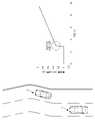
도 9는 합류 구간 도로에서 운동 기대값의 일 예를 도시한다.
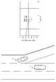
도 10은 공사 구간 도로에서 운동 기대값의 일 예를 도시한다.1 shows a configuration of a vehicle according to an embodiment.
2 is a control block diagram of a vehicle according to an exemplary embodiment.
3 illustrates a camera and a radar included in a driver assistance system according to an embodiment.
4 is a flowchart of a method for controlling a vehicle according to the disclosed invention.
5 is a flowchart referenced to the flowchart of FIG. 4 .
6 illustrates an example of first motion information of an object.
7 shows an example of an expected motion value in a road congestion situation.
8 shows an example of a motion expectation on a curved road.
9 shows an example of an expected motion value on a road in a merging section.
10 shows an example of an expected motion value on a road in a construction section.
명세서 전체에 걸쳐 동일 참조 부호는 동일 구성요소를 지칭한다. 본 명세서가 실시예들의 모든 요소들을 설명하는 것은 아니며, 개시된 발명이 속하는 기술분야에서 일반적인 내용 또는 실시예들 간에 중복되는 내용은 생략한다. 명세서에서 사용되는 '부, 모듈, 부재, 블록'이라는 용어는 소프트웨어 또는 하드웨어로 구현될 수 있으며, 실시예들에 따라 복수의 '부, 모듈, 부재, 블록'이 하나의 구성요소로 구현되거나, 하나의 '부, 모듈, 부재, 블록'이 복수의 구성요소들을 포함하는 것도 가능하다.Like reference numbers designate like elements throughout the specification. This specification does not describe all elements of the embodiments, and general content or overlapping content between the embodiments in the technical field to which the disclosed invention belongs is omitted. The term 'unit, module, member, or block' used in the specification may be implemented as software or hardware, and according to embodiments, a plurality of 'units, modules, members, or blocks' may be implemented as one component, It is also possible that one 'part, module, member, block' includes a plurality of components.
명세서 전체에서, 어떤 부분이 다른 부분과 "연결"되어 있다고 할 때, 이는 직접적으로 연결되어 있는 경우뿐 아니라, 간접적으로 연결되어 있는 경우를 포함하고, 간접적인 연결은 무선 통신망을 통해 연결되는 것을 포함한다.Throughout the specification, when a part is said to be "connected" to another part, this includes not only the case of being directly connected but also the case of being indirectly connected, and indirect connection includes being connected through a wireless communication network. do.
또한 어떤 부분이 어떤 구성요소를 "포함"한다고 할 때, 이는 특별히 반대되는 기재가 없는 한 다른 구성요소를 제외하는 것이 아니라 다른 구성요소를 더 포함할 수 있는 것을 의미한다.In addition, when a certain component is said to "include", this means that it may further include other components without excluding other components unless otherwise stated.
명세서 전체에서, 어떤 부재가 다른 부재 "상에" 위치하고 있다고 할 때, 이는 어떤 부재가 다른 부재에 접해 있는 경우뿐 아니라 두 부재 사이에 또 다른 부재가 존재하는 경우도 포함한다.Throughout the specification, when a member is said to be located “on” another member, this includes not only a case where a member is in contact with another member, but also a case where another member exists between the two members.
제 1, 제 2 등의 용어는 하나의 구성요소를 다른 구성요소로부터 구별하기 위해 사용되는 것으로, 구성요소가 전술된 용어들에 의해 제한되는 것은 아니다.Terms such as first and second are used to distinguish one component from another, and the components are not limited by the aforementioned terms.
단수의 표현은 문맥상 명백하게 예외가 있지 않는 한, 복수의 표현을 포함한다.Expressions in the singular number include plural expressions unless the context clearly dictates otherwise.
각 단계들에 있어 식별부호는 설명의 편의를 위하여 사용되는 것으로 식별부호는 각 단계들의 순서를 설명하는 것이 아니며, 각 단계들은 문맥상 명백하게 특정 순서를 기재하지 않는 이상 명기된 순서와 다르게 실시될 수 있다.In each step, the identification code is used for convenience of description, and the identification code does not explain the order of each step, and each step may be performed in a different order from the specified order unless a specific order is clearly described in context. there is.
이하 첨부된 도면들을 참고하여 개시된 발명의 작용 원리 및 실시예들에 대해 설명한다.Hereinafter, the working principle and embodiments of the disclosed invention will be described with reference to the accompanying drawings.
도 1은 일 실시예에 따른 차량의 구성을 도시하고, 도 2는 일 실시예에 따른 차량의 제어 블록도이고, 도 3은 일 실시예에 따른 운전자 보조 시스템에 포함된 카메라 및 레이더를 도시한다.1 illustrates a configuration of a vehicle according to an embodiment, FIG. 2 is a control block diagram of a vehicle according to an embodiment, and FIG. 3 illustrates a camera and a radar included in a driver assistance system according to an embodiment. .
도 1에 도시된 바와 같이, 차량(1)은 엔진(10)과, 변속기(20)와, 제동 장치(30)와, 조향 장치(40)를 포함한다. 엔진(10)은 실린더와 피스톤을 포함하녀, 차량(1)이 주행하기 위한 동력을 생성할 수 있다. 변속기(20)는 복수의 기어들을 포함하며, 엔진(10)에 의하여 생성된 동력을 차륜까지 전달할 수 있다. 제동 장치(30)는 차륜과의 마찰을 통하여 차량(1)을 감속시키거나 차량(1)을 정지시킬 수 있다. 조향 장치(40)는 차량(1)의 주행 방향을 변경시킬 수 있다.As shown in FIG. 1 , a
차량(1)은 복수의 전장 부품들을 포함할 수 있다. 예를 들어, 차량(1)은 엔진 관리 시스템(Engine Management System, EMS) (11)과, 변속기 제어 유닛(Transmission Control Unit, TCU) (21)과, 전자식 제동 제어 모듈(Electronic Brake Control Module) (31)과, 전자식 조향 장치(Electronic Power Steering, EPS) (41)과, 바디 컨트롤 모듈(Body Control Module, BCM)과, 운전자 보조 시스템(Driver Assistance System, DAS)을 더 포함한다.The
엔진 관리 시스템(11)은 가속 페달을 통한 운전자의 가속 의지 또는 운전자 보조 시스템(100)의 요청에 응답하여 엔진(10)을 제어할 수 있다. 예를 들어, 엔진 관리 시스템(11)은 엔진(10)의 토크를 제어할 수 있다.The
변속기 제어 유닛(21)은 변속 레버를 통한 운전자의 변속 명령 및/또는 차량(1)의 주행 속도에 응답하여 변속기(20)를 제어할 수 있다. 예를 들어, 변속기 제어 유닛(21)은 엔진(10)으로부터 차륜까지의 변속 비율을 조절할 수 있다.The
전자식 제동 제어 모듈(31)은 제동 페달을 통한 운전자의 제동 의지 및/또는 차륜들의 슬립(slip)에 응답하여 제동 장치(30)를 제어할 수 있다. 예를 들어, 전자식 제동 제어 모듈(31)은 차량(1)의 제동 시에 감지되는 차륜의 슬립에 응답하여 차륜의 제동을 일시적으로 해제할 수 있다(Anti-lock Braking Systems, ABS). 전자식 제동 제어 모듈(31)은 차량(1)의 조향 시에 감지되는 오버스티어링(oversteering) 및/또는 언더스티어링(understeering)에 응답하여 차륜의 제동을 선택적으로 해제할 수 있다(Electronic stability control, ESC). 또한, 전자식 제동 제어 모듈(31)은 차량(1)의 구동 시에 감지되는 차륜의 슬립에 응답하여 차륜을 일시적으로 제동할 수 있다(Traction Control System, TCS).The electronic
전자식 조향 장치(41)는 스티어링 휠을 통한 운전자의 조향 의지에 응답하여 운전자가 쉽게 스티어링 휠을 조작할 수 있도록 조향 장치(40)의 동작을 보조할 수 있다. 예를 들어, 전자식 조향 장치(41)는 저속 주행 또는 주차 시에는 조향력을 감소시키고 고속 주행 시에는 조향력을 증가시키도록 조향 장치(40)의 동작을 보조할 수 있다.The
바디 컨트롤 모듈(51)은 운전자에게 편의를 제공하거나 운전자의 안전을 보장하는 전장 부품들의 동작을 제어할 수 있다. 예를 들어, 바디 컨트롤 모듈(51)은 헤드 램프, 와이퍼, 클러스터, 다기능 스위치 및 방향 지시 램프 등을 제어할 수 있다.The
HMI(Human Machine Interface) 장치(61)는 운전자에게 차량(1)의 상태 정보, 동작 정보 등을 시각적, 청각적 또는 촉각적으로 알리는 장치에 해당한다. 예를 들어, HMI 장치(61)는 차량(1) 내부에 마련된 디스플레이(미도시), 스피커(미도시), HUD(Head Up Display, 미도시), LED 조명(미도시), 햅틱 장치(미도시) 등을 포함하며, 제어부(140)의 제어 신호에 따라 다양한 알림을 출력할 수 있다.The HMI (Human Machine Interface)
운전자 보조 시스템(100)은 운전자가 차량(1)을 조작(구동, 제동, 조향)하는 것을 보조할 수 있다. 예를 들어, 운전자 보조 시스템(100)은 차량(1) 주변의 환경(예를 들어, 다른 차량, 보행자, 사이클리스트(cyclist), 차선, 도로 표지판 등)을 감지하고, 감지된 환경에 응답하여 차량(1)의 구동 및/또는 제동 및/또는 조향을 제어할 수 있다.The
운전자 보조 시스템(100)은 운전자에게 다양한 기능을 제공할 수 있다. 예를 들어, 운전자 보조 시스템(100)은 전방 충돌 방지 보조(Forward Collision-Avoidance Assist, FCA), 차선 이탈 경고(Lane Departure Warning, LDW)와, 차선 유지 보조(Lane Keeping Assist, LKA)와, 상향등 보조(High Beam Assist, HBA)와, 자동 긴급 제동(Autonomous Emergency Braking, AEB)과, 교통 표지판 인식(Traffic Sign Recognition, TSR)과, 스마트 크루즈 컨트롤(Smart Cruise Control, SCC)과, 사각지대 감지(Blind Spot Detection, BSD) 등을 제공할 수 있다.The
운전자 보조 시스템(100)은 차량(1) 주변의 영상 데이터를 획득하는 카메라 모듈(101)과, 차량(1) 주변의 레이더 데이터를 획득하는 레이더 모듈(102)을 포함한다. 카메라 모듈(101)은 카메라(101a)와 제어기(Electronic Control Unit, ECU) (101b)를 포함하며, 차량(1)의 전방을 촬영하고 다른 차량, 보행자, 사이클리스트, 차선, 도로 표지판 등을 인식할 수 있다. 레이더 모듈(102)은 레이더(102a)와 제어기(102b)를 포함하며, 차량(1) 주변의 대상체(예를 들어, 다른 차량, 보행자, 사이클리스트 등)의 상대 위치, 상대 속도 등을 획득할 수 있다.The
운전자 보조 시스템(100)은 도 1에 도시된 바에 한정되지 아니하며, 차량(1) 주변을 스캔하며 대상체를 감지하는 라이다(lidar)를 더 포함할 수 있다.The
이상의 전자 부품들은 차량용 통신 네트워크(NT)를 통하여 서로 통신할 수 있다. 예를 들어, 전장 부품들은 이더넷(Ethernet), 모스트(MOST, Media Oriented Systems Transport), 플렉스레이(Flexray), 캔(CAN, Controller Area Network), 린(LIN, Local Interconnect Network) 등을 통하여 데이터를 주고 받을 수 있다. 예를 들어, 운전자 보조 시스템(100)은 엔진 관리 시스템(11), 전자식 제동 제어 모듈(31) 및 전자식 조향 장치(41)에 각각 차량용 통신 네트워크(NT)를 통하여 구동 제어 신호, 제동 신호 및 조향 신호를 전송할 수 있다.The above electronic components may communicate with each other through the vehicle communication network NT. For example, electronic components transmit data through Ethernet, MOST (Media Oriented Systems Transport), Flexray, CAN (Controller Area Network), LIN (Local Interconnect Network), etc. can give and take For example, the
도 2에 도시된 바와 같이, 차량(1)은 제동 시스템(32)과, 조향 시스템(42)과, 운전자 보조 시스템(100)을 포함할 수 있다.As shown in FIG. 2 ,
상술한 바와 같이, 차량(1)은 전방 충돌 방지 보조(Forward Collision-Avoidance Assist, FCA)을 수행하는 운전자 보조 시스템(100)에 따라 대상체의 위치 및 상대 속도에 기초하여 회피 제어를 수행할 수 있다. 여기서, 대상체는 다른 차량, 보행자, 사이클리스트 등을 의미하며, 주행 중인 차량(1)이 회피해야할 모든 대상을 의미한다.As described above, the
제동 시스템(32)은 도 1과 함께 설명된 전자식 제동 제어 모듈(31, 도 1 참조)과 제동 장치(30, 도 1 참조)를 포함하며, 조향 시스템(42)은 전자식 조향 장치(41, 도 1 참조)와 조향 장치(40, 도 1 참조)를 포함할 수 있다.The
운전자 보조 시스템(100)은 전방 카메라(110)와, 전방 레이더(120)와, 복수의 코너 레이더들을 포함할 수 있다. 전방 카메라(110), 전방 레이더(120) 및 복수의 코너 레이더(미도시)는 차량(1)의 외부에 있는 대상체를 감지하기 위한 센서로써, 이는 센서(미도시)로 통칭할 수 있다.The
센서는 대상체를 감지하고, 대상체에 관한 데이터를 획득하여 제어부(140)에 제공할 수 있다. 이 때, 대상체 데이터는 전방 카메라(110)로부터 획득한 영상 데이터, 전방 레이더(120) 및/또는 코너 레이더로부터 획득한 레이더 데이터를 포함할 수 있다.The sensor may detect an object, obtain data about the object, and provide the obtained data to the
전방 카메라(110)는 도 3에 도시된 바와 같이 차량(1)의 전방을 향하는 시야(field of view) (110a)를 가질 수 있다. 전방 카메라(110)는 예를 들어 차량(1)의 프론트 윈드 쉴드에 설치될 수 있다.As shown in FIG. 3 , the
전방 카메라(110)는 차량(1)의 전방을 촬영하고, 차량(1) 전방의 영상 데이터를 획득할 수 있다. 차량(1) 전방의 영상 데이터는 차량(1) 전방에 위치하는 다른 차량 또는 보행자 또는 사이클리스트 또는 차선에 관한 위치를 포함할 수 있다.The
전방 카메라(110)는 복수의 렌즈들 및 이미지 센서를 포함할 수 있다. 이미지 센서는 광을 전기 신호로 변환하는 복수의 포토 다이오드들을 포함할 수 있으며, 복수의 포토 다이오드들이 2차원 매트릭스로 배치될 수 있다.The
전방 카메라(110)는 제어부(140)와 전기적으로 연결될 수 있다. 예를 들어, 전방 카메라(110)는 차량용 통신 네트워크(NT)를 통하여 제어부(140)와 연결되거나, 하드 와이어(hard wire)를 통하여 제어부(140)와 연결되거나, 인쇄 회로 기판(Printed Circuit Board, PCB)을 통하여 제어부(140)와 연결될 수 있다.The
전방 카메라(110)는 차량(1) 전방의 영상 데이터를 제어부(140)로 전달할 수 있다.The
전방 레이더(120)는 도 3에 도시된 바와 같이 차량(1)의 전방을 향하는 감지 시야(field of sensing) (120a)을 가질 수 있다. 전방 레이더(120)는 예를 들어 차량(1)의 그릴(grille) 또는 범퍼(bumper)에 설치될 수 있다.As shown in FIG. 3 , the
전방 레이더(120)는 차량(1)의 전방을 향하여 송신 전파를 방사하는 송신 안테나(또는 송신 안테나 어레이)와, 대상체에 반사된 반사 전파를 수신하는 수신 안테나(또는 수신 안테나 어레이)를 포함할 수 있다. 전방 레이더(120)는 송신 안테나에 의한 송신된 송신 전파와 수신 안테나에 의하여 수신된 반사 전파로부터 전방 레이더 데이터를 획득할 수 있다. 전방 레이더 데이터는 차량(1) 전방에 위치하는 다른 차량 또는 보행자 또는 사이클리스트에 관한 거리 정보 및 속도 정도를 포함할 수 있다. 전방 레이더(120)는 송신 전파와 반사 전파 사이의 위상 차이(또는 시간 차이)에 기초하여 대상체까지의 상태 거리를 산출하고, 송신 전파와 반사 전파 사이의 주파수 차이에 기초하여 대상체의 상대 속도를 산출할 수 있다.The
전방 레이더(120)는 예를 들어 차량용 통신 네트워크(NT) 또는 하드 와이어 또는 인쇄 회로 기판을 통하여 제어부(140)와 연결될 수 있다. 전방 레이더(120)는 전방 레이더 데이터를 제어부(140)로 전달할 수 있다.The
동역학 센서(130)는 차량(1)의 움직임을 검출하고, 차량의 움직임에 기초한 운동 데이터를 획득한다. 운동 데이터는 차량(1)의 주행 속도, 조향각, 요 레이트에 관한 정보를 포함한다. 동역학 센서(130)는 휠 속도 센서, 조향각 센서, 요 레이트 센서 등의 다양한 공지의 센서로서, 차량의 휠, 핸들 등 적절한 위치에 배치되어 차량의 주행 속도, 조향각, 요 레이트 등을 감지하여 제어부(140)에 전송할 수 있다.The
복수의 코너 레이더들은 차량(1)의 전방 우측에 설치되는 제1 코너 레이더(131)와, 차량(1)의 전방 좌측에 설치되는 제2 코너 레이더(132)와, 차량(1)의 후방 우측에 설치되는 제3 코너 레이더(133)와, 차량(1)의 후방 좌측에 설치되는 제4 코너 레이더(134)를 포함한다.The plurality of corner radars include a
제1 코너 레이더(131)는 도 3에 도시된 바와 같이 차량(1)의 전방 우측을 향하는 감지 시야(131a)를 가질 수 있다. 전방 레이더(120)는 예를 들어 차량(1)의 전방 범퍼의 우측에 설치될 수 있다. 제2 코너 레이더(132)는 차량(1)의 전방 좌측을 향하는 감지 시야(132a)를 가질 수 있으며, 예를 들어 차량(1)의 전방 범퍼의 좌측에 설치될 수 있다. 제3 코너 레이더(133)는 차량(1)의 후방 우측을 향하는 감지 시야(133a)를 가질 수 있으며, 예를 들어 차량(1)의 후방 범퍼의 우측에 설치될 수 있다. 제4 코너 레이더(134)는 차량(1)의 후방 좌측을 향하는 감지 시야(134a)를 가질 수 있으며, 예를 들어 차량(1)의 후방 범퍼의 좌측에 설치될 수 있다.As shown in FIG. 3 , the
제1, 제2, 제3 및 제4 코너 레이더들(131, 132, 133, 134) 각각은 송신 안테나와 수신 안테나를 포함할 수 있다. 제1, 제2, 제3 및 제4 코너 레이더들(131, 132, 133, 134)은 각각 제1 코너 레이더 데이터와 제2 코너 레이더 데이터와 제3 코너 레이더 데이터와 제4 코너 레이더 데이터를 획득할 수 있다. 제1 코너 레이더 데이터는 차량(1) 전방 우측에 위치하는 다른 차량 또는 보행자 또는 사이클리스트(이하 "대상체"라 한다)에 관한 거리 정보 및 속도 정도를 포함할 수 있다. 제2 코너 레이더 데이터는 차량(1) 전방 좌측에 위치하는 대상체의 거리 정보 및 속도 정도를 포함할 수 있다. 제3 및 제4 코너 레이더 데이터는 차량(1) 후방 우측 및 차량(1) 후방 좌측에 위치하는 대상체의 거리 정보 및 상대 속도를 포함할 수 있다.Each of the first, second, third, and
제1, 제2, 제3 및 제4 코너 레이더들(131, 132, 133, 134) 각각은 예를 들어 차량용 통신 네트워크(NT) 또는 하드 와이어 또는 인쇄 회로 기판을 통하여 제어부(140)와 연결될 수 있다. 제1, 제2, 제3 및 제4 코너 레이더들(131, 132, 133, 134)은 각각 제1, 제2, 제3 및 제4 코너 레이더 데이터를 제어부(140)로 전달할 수 있다.Each of the first, second, third, and
제어부(140)는 카메라 모듈(101, 도 1 참조)의 제어기(101b, 도 1 참조) 및/또는 레이더 모듈(102, 도 1 참조)의 제어기(102b, 도 1 참조) 및/또는 별도의 통합 제어기를 포함할 수 있다.The
제어부(140)는 프로세서(141)와 메모리(142)를 포함한다.The
프로세서(141)는 전방 카메라(110)의 전방 영상 데이터와 전방 레이더(120)의 전방 레이더 데이터와 복수의 코너 레이더들의 코너 레이더 데이터를 처리하고, 제동 시스템(32) 및 조향 시스템(42)을 제어하기 위한 제동 신호 및 조향 신호를 생성할 수 있다. 예를 들어, 프로세서(141)는 전방 카메라(110)의 전방 영상 데이터를 처리하는 이미지 프로세서 및/또는 레이더들(120)의 레이더 데이터를 처리하는 디지털 시그널 프로세서 및/또는 제동 신호와 조향 신호를 생성하는 마이크로 컨트롤 유닛(Micro Control Unit, MCU)를 포함할 수 있다.The
프로세서(141)는 전방 카메라(110)의 전방 영상 데이터와 전방 레이더(120)의 전방 레이더 데이터에 기초하여 차량(1) 전방의 대상체들(예를 들어, 다른 차량, 보행자, 사이클리스트 등)을 감지할 수 있다.The
구체적으로, 프로세서(141)는 전방 레이더(120)의 전방 레이더 데이터에 기초하여 차량(1) 전방의 대상체들의 위치(거리 및 방향) 및 상대 속도를 획득할 수 있다. 프로세서(141)는 전방 카메라(110)의 전방 영상 데이터에 기초하여 차량(1) 전방의 대상체들의 위치(방향) 및 유형 정보(예를 들어, 대상체가 다른 차량인지, 또는 보행자인지, 또는 사이클리스트인지 등)를 획득할 수 있다. 또한, 프로세서(141)는 전방 영상 데이터에 의하여 감지된 대상체들을 전방 레이더 데이터에 의한 감지된 대상체에 매칭하고, 매칭 결과에 기초하여 차량(1)의 전방 대상체들의 유형 정보와 위치와 상대 속도를 획득할 수 있다.Specifically, the
프로세서(141)는 전방 대상체들의 유형 정보와 위치와 상대 속도에 기초하여 제동 신호와 조향 신호를 생성할 수 있다.The
예를 들어, 프로세서(141)는 전방 대상체들의 위치(거리)와 상대 속도에 기초하여 차량(1)과 전방 대상체 사이의 충돌까지의 시간(Time to Collision, TTC)를 산출하고, 충돌까지의 시간(TTC)과 미리 정해진 기준 시간 사이의 비교에 기초하여 운전자에게 충돌을 경고하거나 제동 신호를 제동 시스템(32)으로 전송하거나 조향 신호를 조향 시스템(42)로 전송할 수 있다.For example, the
다른 예로, 프로세서(141)는 전방 대상체들의 상대 속도에 기초하여 충돌까지의 거리(Distance to Collision, DTC)를 산출하고, 충돌까지의 거리와 전방 대상체들까지의 거리 사이의 비교에 기초하여 운전자에게 충돌을 경고하거나 제동 신호를 제동 시스템(32)으로 전송하거나 조향 신호를 조향 시스템(42)로 전송할 수 있다.As another example, the
프로세서(141)는 복수의 코너 레이더들의 코너 레이더 데이터에 기초하여 차량(1)의 측방(전방 우측, 전방 좌측, 후방 우측, 후방 좌측) 대상체들의 위치(거리 및 방향) 및 상대 속도를 획득할 수 있다.The
프로세서(141)는 차량(1)의 측방 대상체들의 위치(거리 및 방향) 및 상대 속도에 기초하여 조향 신호를 조향 시스템(42)으로 전송할 수 있다.The
예를 들어, 충돌까지의 시간 또는 충돌까지의 거리에 기초하여 전방 대상체와의 충돌이 판단되면, 프로세서(141)는 전방 대상체와의 충돌을 회피하기 위하여 조향 신호를 조향 시스템(42)으로 전송할 수 있다.For example, if a collision with a front object is determined based on the time to collision or the distance to collision, the
프로세서(141)는 차량(1)의 측방 대상체들의 위치(거리 및 방향) 및 상대 속도에 기초하여 차량(1)의 주행 방향을 변경함으로써 전방 대상체와의 충돌을 회피할지 여부를 판단할 수 있다. 예를 들어, 차량(1)의 측방에 위치하는 대상체가 없으면, 프로세서(141)는 전방 대상체와의 충돌을 회피하기 위하여 조향 신호를 조향 시스템(42)으로 전송할 수 있다. 측방 대상체들의 위치(거리 및 방향) 및 상대 속도에 기초하여 차량(1)의 조향 이후 측방 대상체와의 충돌이 예측되지 않으면, 프로세서(141)는 전방 대상체와의 충돌을 회피하기 위하여 조향 신호를 조향 시스템(42)으로 전송할 수 있다. 측방 대상체들의 위치(거리 및 방향) 및 상대 속도에 기초하여 차량(1)의 조향 이후 측방 대상체와의 충돌이 예측되면, 프로세서(141)는 조향 신호를 조향 시스템(42)으로 전송하지 아니할 수 있다.The
프로세서(141)는 내비게이터(21)로부터 위치 정보를 제공받고, 위치 정보에 기초하여 운동 기대값을 서버(미도시) 또는 메모리(142)로부터 획득한다.The
내비게이터(21)는 교통 흐름 제어 및 동적 경로 제공을 위한 적어도 하나의 장치들과 양방향 통신을 함으로써 정보를 송수신할 수 있다. 예컨대, 내비게이터(21)는 GPS 위성을 통해 차량의 위치 정보를 획득하고, 획득한 위치 정보와 함께 운전자(또는 탑승자)가 입력한 출발지/목적지 정보 및 차량 속도 정보를 서버로 전송하고, 서버는 내비게이터(21)로 교통망 정보, 목적지까지의 최적 경로 정보 등을 제공할 수 있다. 이 때, 내비게이터(21)는 차량(1)에 기 설치된 장치이거나, 차량(1)과 유무선 통신을 통해 데이터를 송수신할 수 있는 장치일 수 있다.The
프로세서(141)는 내비게이터(21)로부터 획득한 위치 정보에 기초하여 차량(1)이 주행 중인 지역에 대응하는 운동 기대값을 서버 또는 메모리(142)로부터 획득할 수 있다. 이 때, 운동 기대값은 차량(1)이 주행 중인 해당 지역에 다른 차량들의 운동 데이터를 누적하여 도출한 통계치에 해당할 수 있다. 운동 기대값은 차량(1)이 주행 중인 해당 지역을 통과한 복수의 다른 차량의 위치 및 속도가 누적된 데이터일 수 있다. 예를 들어, 운동 기대값은 해당 지역을 정밀 맵으로 구현하여, 정밀 맵 위에 다른 차량들의 과거 경로들을 절대 좌표로 하여 평균화한 데이터에 해당한다. 이 때의 운동 기대값은 정밀 맵 상에서의 횡 위치 및 종 위치로 구현될 수 있다. 물론, 운동 기대값은 횡 위치 및 종 위치의 변화를 통해 과거 다른 차량들이 통상적으로 이동하는 방향에 관한 정보를 나타낼 수 있다.The
또한, 운동 기대값은 정밀 맵 상에서의 횡 위치 및 종 위치에 대한 미분을 통해 횡 속도 및 종 속도로 구현될 수 있다. 또한, 운동 기대값은 정밀 맵 상에서의 횡 속도 및 종 속도에 대한 미분을 통해 횡 가속도 및 종 가속도로 구현될 수 있다.In addition, the expected motion value may be implemented as lateral speed and longitudinal speed through differentiation of the lateral and longitudinal positions on the precise map. In addition, the expected motion value may be implemented as lateral acceleration and longitudinal acceleration through differentiation of lateral and longitudinal velocities on a precise map.
상술한 운동 기대값은 서버가 다른 차량들로부터 지속적으로 데이터를 수집하여 생성된다. 차량(1)은 운동 기대값을 서버로부터 실시간으로 획득하거나, 메모리(142)에 기 저장된 운동 기대값을 이용할 수 있다.The aforementioned expected motion value is generated by the server continuously collecting data from other vehicles. The
개시된 발명은 상술한 운동 기대값을 기초로 하여 차량(1) 주변에서 주행 중인 다른 차량들 중 위험 대상 차량을 판단하기 위한 것이다. 운동 기대값을 이용하는 구체적인 실시예는 도 4 내지 도 10을 참조하여 후술하도록 한다.The disclosed invention is to determine a vehicle subject to danger among other vehicles running around the
메모리(142)는 프로세서(141)가 영상 데이터를 처리하기 위한 프로그램 및/또는 데이터와, 레이더 데이터를 처리하기 위한 프로그램 및/또는 데이터와, 프로세서(141)가 제동 신호 및/또는 조향 신호를 생성하기 위한 프로그램 및/또는 데이터를 저장할 수 있다.The
메모리(142)는 전방 카메라(110)로부터 수신된 영상 데이터 및/또는 레이더들(120)로부터 수신된 레이더 데이터를 임시로 기억하고, 프로세서(141)의 영상 데이터 및/또는 레이더 데이터의 처리 결과를 임시로 기억할 수 있다.The
메모리(142)는 S램(S-RAM), D램(D-RAM) 등의 휘발성 메모리뿐만 아니라 플래시 메모리, 롬(Read Only Memory, ROM), 이피롬(Erasable Programmable Read Only Memory: EPROM) 등의 비휘발성 메모리를 포함할 수 있다.The
운전자 보조 시스템(100)은 도 2에 도시된 바에 한정되지 아니하며, 차량(1) 주변을 스캔하며 대상체를 감지하는 라이다(lidar)를 더 포함할 수 있다.The
이처럼, 제어부(140)는 전방 대상체와의 충돌이 예측되는지 여부에 기초하여 제동 신호를 제동 시스템(32)으로 전송할 수 있다. 측방 대상체가 존재하지 아니하거나 측방 대상체와의 충돌이 예측되지 않으면 제어부(140)는 전방 대상체와의 충돌을 회피하기 위하여 조향 신호를 조향 시스템(42)으로 전송할 수 있다. 조향 이후 측방 대상체와의 충돌이 예측되면 제어부(140)는 조향 신호를 조향 시스템(42)으로 전송하지 아니할 수 있다.As such, the
이상에서는 개시된 발명이 구현되기 위한 구성 및 각 구성 별 동작에 대해 설명하였다. 이하에서는 상술한 구성을 토대로 위험 대상체를 판단하고, 위험 대상체에 기초하여 알림 제어, 제동 제어 및 조향 제어를 수행하는 과정에 대해 설명한다.In the above, configurations for implementing the disclosed invention and operations for each configuration have been described. Hereinafter, a process of determining a dangerous object based on the above configuration and performing notification control, braking control, and steering control based on the dangerous object will be described.
도 4는 개시된 발명에 따른 차량의 제어 방법의 순서도이다. 도 4는 도 5를 함께 참조하여 설명한다.4 is a flowchart of a method for controlling a vehicle according to the disclosed invention. 4 will be described with reference to FIG. 5 together.
차량(1)은 대상체의 운동 상태 정보를 획득한다(401). 대상체의 운동 상태 정보는 상술한 운동 기대값과 비교하기 위한 데이터로써, 차량(1)이 주행 중인 해당 지역에서 있어 차량(1)과의 충돌 가능성이 있거나, 차량(1)의 주행에 영향을 줄 수 있는지 판단하기 위해 획득된다. 여기서, 대상체는 도로에서 차량(1) 이외의 충돌 가능성이 있는 다른 차량들을 가리킨다.The
차량(1)은 위치 정보를 획득한다(402). 위치 정보는 차량(1)에 마련된 내비게이터(21)로부터 획득될 수 있다. 위치 정보는 차량(1)이 위치한 곳의 도로 특성 또는 도로 유형 등을 파악하여 이에 대응되는 운동 기대값을 제공하기 위한 것이다. 운동 기대값은 차량(1)이 주행 중인 해당 지역에 다른 차량들의 운동 데이터를 누적하여 도출한 통계치에 해당할 수 있다.The
차량(1)은 위치 정보에 기초하여 운동 기대값을 획득한다(403). 차량(1)은 위치 정보를 수신하면 해당 지역에 대응되는 정밀 맵을 제공할 수 있고, 정밀 맵을 기준으로 하는 다른 차량 들의 운동 기대값을 획득할 수 있다.The
차량(1)은 대상체의 운동 상태 정보와 운동 기대값 간의 차이값을 산출한다(404). 이와 관련하여 도 5를 참조하여 더욱 상세히 설명한다.The
개시된 발명은 차량(1) 주변에서 주행 중인 다른 차량의 거동과 통상적인 과거 차량들의 거동을 비교하여 다른 차량이 전형적인 거동을 보이지 않는 경우, 위험 대상체로 판단하고, 위험 대상체를 관심 대상으로 하여 알림 제어, 제동 제어 및 조향 제어를 수행하기 위한 것이다.The disclosed invention compares the behavior of other vehicles driving around the
이를 위해, 차량(1)은 현재 주행 중인 대상체와 과거 다른 차량 간의 거동의 차이를 판단하기 위해, 도 5에 따른 일련과 과정을 수행할 수 있다.To this end, the
차량(1)은 제1 운동 정보를 획득하고(501), 운동 기대값을 획득한다(502). 이 때, 제1 운동 정보는 주행 중인 대상체의 운동 상태 정보에 관한 것으로써, 차량(1)을 기준으로한 대상체의 상대 위치, 상대 속도, 상대 가속도, 차량 크기, 차량 종류 및 진행 방향을 포함할 수 있다.The
차량(1)은 제1 운동 정보를 제1 절대 좌표로 변환하고(503), 운동 기대값을 제2 절대 좌표로 변환한다(504). 절대 좌표는 각각의 수치들을 정량적으로 비교하기 위한 것으로써, 정밀 맵 상에 횡 위치 및 종 위치가 반영된 데이터에 해당한다. 또한, 운동 기대값은 정밀 맵 상에서 횡 위치 및 종 위치에 대한 미분을 통해 절대 좌표 방식으로 횡 속도 및 종 속도로 구현될 수 있다. 또한, 운동 기대값은 정밀 맵 상에서 횡 속도 및 종 속도에 대한 미분을 통해 절대 좌표 방식으로 횡 가속도 및 종 가속도로 구현될 수 있다.The
도 5를 참조하여 제1 운동 정보의 일 예를 참조하면, 제1 운동 정보는 차량(1)을 기준으로 대상체(2)의 상대 위치를 획득하여, 정밀 맵 상의 종 방향 위치 정보 및 횡 방향 위치 정보를 획득한다. 이를 운동 기대값과 비교하기 위하여 시간 흐름에 따른 그래프로 나타내면 도 5에 도시된 바와 같다. 차량(1)과 대상체(2)가 나란히 주행하는 도로 구간에서는 횡 방향 성분은 큰 차이가 없을 것이며, 종 방향 성분은 대상체(2)의 가속 또는 감속에 따라 어느 정도의 차이를 보일 것이다. 만약, 대상체(2)의 횡 방향 성분에 큰 변동이 생기면, 대상체(2)가 차선 변경을 의도하거나, 불안정한 주행 상황인 것으로 예측할 수 있다.Referring to FIG. 5 as an example of the first motion information, the first motion information obtains the relative position of the
차량(1)은 제1 절대 좌표의 성분과 제2 절대 좌표의 성분을 비교하여(505), 해당 지역에서 대상체의 거동이 과거에 정상적인 다른 차량의 거동에서 벗어나는지 판단할 수 있다.The
다시, 도 4를 참조하면 산출된 차이값을 미리 정해진 수치와 비교하여(405), 차이값이 미리 정해진 수치 이상이면 대상체를 위험 대상체로 판단한다(406).Again, referring to FIG. 4 , the calculated difference value is compared with a predetermined value (405), and if the difference value is greater than or equal to the predetermined value, the object is determined to be a dangerous object (406).
차이값은 정밀 맵 상의 방향 차이값, 위치 차이값, 속도 차이값 또는 가속도 차이값 중 하나가 될 수 있다. 차이값의 대상은 차량(1)이 통과하는 해당 지역에 따라 선택될 수 있다. 해당 지역에 따른 실시예를 도 7 내지 도 10을 참조하여 상세히 설명한다.The difference value may be one of a direction difference value, a position difference value, a speed difference value, or an acceleration difference value on a precision map. An object of the difference value may be selected according to a corresponding area through which the
도 7은 도로의 정체 상황에서 운동 기대값의 일 예를 도시하고, 도 8은 곡선 도로에서 운동 기대값의 일 예를 도시하고, 도 9는 합류 구간 도로에서 운동 기대값의 일 예를 도시하고, 도 10은 공사 구간 도로에서 운동 기대값의 일 예를 도시한다.FIG. 7 shows an example of an expected motion value in a congestion situation on a road, FIG. 8 shows an example of an expected motion value on a curved road, and FIG. 9 shows an example of an expected motion value on a merging road. , FIG. 10 shows an example of an expected motion value on a road in a construction section.
도 7을 참조하면, 해당 지역은 도로가 정체 상황인 구간으로써, 복수의 대상체(2-1 내지 2-5)의 운동 기대값 중 종 방향 속도 성분은 일정 범위 내에서 증감하는 양상을 보인다. 이 경우, 복수의 대상체(2-1 내지 2-5) 중 적어도 하나가 종 방향 속도 값이 운동 기대값의 범위를 벗어난 경우, 차량(1)은 운동 기대값의 범위를 벗어난 대상체를 위험 대상체로 판단할 수 있다. 따라서, 본 실시예에서는 위치 정보를 통해 해당 지역이 정체 구간인 것으로 판단되면, 제1 절대 좌표와 제2 절대 좌표의 비교 대상을 종 방향 속도 값으로 결정할 수 있다. 이 경우, 차량(1)은 종 방향 속도 차이값이 미리 정해진 수치 이상에 해당하는 대상체를 위험 대상체로 판단하고, 위험 대상체가 교통 체증을 유발할 것으로 판단할 수 있다.Referring to FIG. 7 , the corresponding region is a section in which the road is congested, and the longitudinal velocity component among expected motion values of the plurality of objects 2-1 to 2-5 shows an increase or decrease within a certain range. In this case, if at least one of the plurality of objects 2-1 to 2-5 has a longitudinal speed value outside the range of the expected motion value, the
또한, 차량(1)은 종 방향에 대한 제1 절대 좌표의 위치 별 제1 속도 변화량과 제2 절대 좌표의 위치 별 제2 속도 변화량 간의 차이가 미리 정해진 수치 이상이면 위험 대상체가 급정거 차량인 것으로 판단할 수 있다.In addition, the
또한, 차량(1)은 횡 방향에 대한 제1 절대 좌표의 위치 별 제1 속도 변화량과 제2 절대 좌표의 위치 별 제2 속도 변화량 간의 차이가 미리 정해진 수치 이상이면 위험 대상체가 난폭 운전 차량인 것으로 판단할 수 있다.In addition, in the
차량(1)은 HMI 장치를 통해 해당 위험 대상체에 대한 정보를 표시하거나, 자율 주행 모드에서 해당 위험 대상체를 회피하도록 조향 제어를 수행할 수 있다.The
차량(1)은 충돌 회피 대상의 우선 순위를 운동 기대값의 범위를 벗어난 대상체를 최우선 순위로 하여 제동 제어 또는 조향 제어를 수행할 수 있다. 또한, 차량(1)은 차량(1)과 복수의 대상체(2-1 내지 2-5)를 HMI 장치에 정밀 맵으로 표현하여 운동 기대값의 범위를 벗어난 차량에 대해 시각적으로 표시할 수 있다. 또한, 차량(1)은 운동 기대값을 벗어난 정도에 따라 색상을 달리하여 HMI 장치에 각 대상체에 표시할 수 있다.The
결국, 차량(1)은 해당 지역이 차로 변경이 어려운 정체 상황인 구간에서, 차이값의 대상을 종 방향 속도로 하여 가속 또는 감속을 과도하게 수행하는 대상체를 위험 대상체로 판단할 수 있다.As a result, the
다음으로, 도 8을 참조하면, 해당 지역은 곡선 도로인 구간으로써, 대상체(2)가 곡선 구간을 따라 주행하게 되면 차량(1)에 대한 대상체(2)의 횡 방향 위치가 급격히 변화할 수 있는 구간이다. 이 때, 곡선 구간에서는 대상체(2)의 횡방향 위치가 급격히 변화하지 않으면, 차량(1)의 진로를 방해하거나 추돌이 예상된다. 따라서, 본 실시예에서는 위치 정보를 통해 해당 지역이 곡선 도로인 것으로 판단되면, 제1 절대 좌표와 제2 절대 좌표의 비교 대상을 횡방향 위치로 결정할 수 있다. 예를 들어, 차량(1)은 대상체(2)의 횡방향 위치가 도 8에 도시된 수치와 큰 격차를 보이는 경우, 대상체(2)를 위험 대상체로 판단할 수 있다.Next, referring to FIG. 8 , the corresponding area is a section of a curved road, and when the
이 때, 차량(1)은 차량(1)과 대상체(2)를 HMI 장치에 정밀 맵으로 표현하여 운동 기대값의 범위나 위험 대상체인 것을 운전자에게 알릴 수 있다. 또한, 차량(1)은 스피커 또는 햅틱 장치를 통해 경고음 또는 진동을 발생시켜 운전자에게 위험 대상체가 주변에 있음을 알릴 수 있다.At this time, the
유사한 예로, 도 9를 참조하면, 해당 지역은 합류 구간으로써, 대상체(2)가 합류 구간 진입 시점을 기준으로 횡방향 위치가 급격히 변하는 것을 예상할 수 있다. 도 8의 실시예와 마찬가지로, 합류 구간에서도 제1 절대 좌표와 제2 절대 좌표의 비교 대상을 횡방향 위치로 결정할 수 있으며, 차량(1)은 대상체의 횡방향 위치가 도 9에 수치와 큰 격차를 보이는 경우, 대상체(2)를 위험 대상체로 판단할 수 있다. 위험 대상체로 판단한 이후의 제어 과정은 도 8의 실시예가 준용될 수 있다.As a similar example, referring to FIG. 9 , the corresponding region is a confluence section, and it can be expected that the position of the
한편, 도 10을 참조하면, 해당 지역은 공사 구간으로써, 대상체(2)가 공사 구간에 진입할 때 감속과 함께 차로를 변경할 것을 예상할 수 있다. 본 실시예에서는 위치 정보를 통해 해당 지역이 공사 구간인 것으로 판단되면, 제1 절대 좌표와 제2 절대 좌표의 비교 대상을 횡방향 위치 및 종방향 속도로 결정할 수 있다. 따라서, 차량(1)은 대상체(2)의 횡방향 위치와 종방향 속도 모두가 도 10에 도시된 그래프 수치에서 큰 격차를 보이는 경우, 대상체(2)를 위험 대상체로 판단할 수 있다.On the other hand, referring to FIG. 10, the corresponding area is a construction section, and when the
이 때, 차량(1)은 차량(1)과 대상체(2)를 HMI 장치에 정밀 맵으로 표현하여 운동 기대값의 범위나 위험 대상체인 것을 운전자에게 알릴 수 있다. 또한, 차량(1)은 스피커 또는 햅틱 장치를 통해 경고음 또는 진동을 발생시켜 운전자에게 위험 대상체가 주변에 있음을 알릴 수 있다.At this time, the
한편, 개시된 실시예들은 컴퓨터에 의해 실행 가능한 명령어를 저장하는 기록매체의 형태로 구현될 수 있다. 명령어는 프로그램 코드의 형태로 저장될 수 있으며, 프로세서에 의해 실행되었을 때, 프로그램 모듈을 생성하여 개시된 실시예들의 동작을 수행할 수 있다. 기록매체는 컴퓨터로 읽을 수 있는 기록매체로 구현될 수 있다.Meanwhile, the disclosed embodiments may be implemented in the form of a recording medium storing instructions executable by a computer. Instructions may be stored in the form of program codes, and when executed by a processor, create program modules to perform operations of the disclosed embodiments. The recording medium may be implemented as a computer-readable recording medium.
컴퓨터가 읽을 수 있는 기록매체로는 컴퓨터에 의하여 해독될 수 있는 명령어가 저장된 모든 종류의 기록 매체를 포함한다. 예를 들어, ROM(Read Only Memory), RAM(Random Access Memory), 자기 테이프, 자기 디스크, 플래시 메모리, 광 데이터 저장장치 등이 있을 수 있다.Computer-readable recording media include all types of recording media in which instructions that can be decoded by a computer are stored. For example, there may be read only memory (ROM), random access memory (RAM), a magnetic tape, a magnetic disk, a flash memory, an optical data storage device, and the like.
이상에서와 같이 첨부된 도면을 참조하여 개시된 실시예들을 설명하였다. 본 발명이 속하는 기술분야에서 통상의 지식을 가진 자는 본 발명의 기술적 사상이나 필수적인 특징을 변경하지 않고도, 개시된 실시예들과 다른 형태로 본 발명이 실시될 수 있음을 이해할 것이다. 개시된 실시예들은 예시적인 것이며, 한정적으로 해석되어서는 안 된다.As above, the disclosed embodiments have been described with reference to the accompanying drawings. Those skilled in the art to which the present invention pertains will understand that the present invention can be implemented in a form different from the disclosed embodiments without changing the technical spirit or essential features of the present invention. The disclosed embodiments are illustrative and should not be construed as limiting.
Claims (20)
Translated fromKorean차량의 위치 정보를 획득하기 위한 내비게이터; 및
상기 위치 정보 및 상기 제1 운동 정보를 처리하는 적어도 하나의 프로세서를 포함하는 제어부;를 포함하고,
상기 제어부는,
상기 위치 정보에 기초하여 상기 대상체의 운동 기대값을 수신하고, 상기 운동 기대값과 상기 제1 운동 정보를 비교하여 차이값을 산출하고, 상기 차이값이 미리 정해진 수치 이상이면 상기 대상체를 위험 대상체로 판단하는 차량.a sensor for obtaining first motion information that is motion state information of an object;
a navigator for acquiring vehicle location information; and
A control unit including at least one processor for processing the location information and the first exercise information;
The control unit,
An expected motion value of the object is received based on the location information, a difference value is calculated by comparing the expected motion value and the first motion information, and when the difference value is equal to or greater than a predetermined value, the object is classified as a risk subject. car to judge.
상기 제어부는,
상기 운동 기대값이 저장된 메모리 또는 서버로부터 상기 운동 기대값을 수신하는 차량.According to claim 1,
The control unit,
A vehicle that receives the expected exercise value from a memory or a server in which the expected exercise value is stored.
상기 운동 기대값은,
상기 차량이 주행 중인 해당 지역을 통과한 복수의 다른 차량의 위치 및 속도가 누적된 데이터인 차량.According to claim 1,
The expected value of the exercise is
A vehicle in which the location and speed of a plurality of other vehicles that have passed through a corresponding area in which the vehicle is driving is accumulated data.
상기 제어부는,
상기 제1 운동 정보에 포함된 상대 거리를 상기 차량을 기준으로 하는 제1 절대 좌표로 변환하고, 상기 운동 기대값은 상기 차량을 기준으로 상기 복수의 다른 차량의 위치를 제2 절대 좌표로 변환된 것인 차량.According to claim 1,
The control unit,
The relative distance included in the first motion information is converted into first absolute coordinates based on the vehicle, and the expected motion value is converted into second absolute coordinates of the positions of the plurality of other vehicles based on the vehicle. vehicle that will be.
상기 제어부는,
상기 제1 절대 좌표와 상기 제2 절대 좌표를 비교하여 위치 차이값을 산출하고, 상기 위치 차이값이 미리 정해진 수치 이상이면 위험 대상체로 판단하는 차량.According to claim 4,
The control unit,
A vehicle that compares the first absolute coordinates with the second absolute coordinates to calculate a position difference value, and determines that the vehicle is a dangerous object if the position difference value is equal to or greater than a predetermined value.
상기 제어부는,
상기 제1 절대 좌표의 위치 별 속도와 상기 제2 절대 좌표 별 속도와 비교하여 속도 차이값을 산출하고, 상기 속도 차이값이 미리 정해진 수치 이상이면 상기 위험 대상체가 교통 체증을 유발하는 것으로 판단하는 차량.According to claim 4,
The control unit,
A vehicle that calculates a speed difference by comparing the speed for each position of the first absolute coordinates with the speed for each second absolute coordinate, and determines that the dangerous object causes traffic jam when the speed difference is equal to or greater than a predetermined value. .
상기 제어부는,
상기 차량의 주행 방향인 제1 방향에 대한 상기 제1 절대 좌표의 위치 별 제1 속도 변화량과 상기 제2 절대 좌표의 위치 별 제2 속도 변화량 간의 차이가 미리 정해진 수치 이상이면 상기 위험 대상체가 급정거 차량인 것으로 판단하는 차량.According to claim 4,
The control unit,
When the difference between the first speed change per position of the first absolute coordinates and the second speed change per position of the second absolute coordinates in the first direction, which is the driving direction of the vehicle, is equal to or greater than a predetermined value, the dangerous object is a vehicle suddenly stopping. A vehicle judged to be
상기 제어부는,
상기 제1 방향과 수직인 제2 방향에 대한 상기 제1 절대 좌표의 위치 별 제1 속도 변화량과 상기 제2 절대 좌표의 위치 별 제2 속도 변화량 간의 차이가 미리 정해진 수치 이상이면 상기 위험 대상체가 난폭 운전 차량인 것으로 판단하는 차량.According to claim 5,
The control unit,
When the difference between the first velocity change per position of the first absolute coordinate and the second velocity change per position of the second absolute coordinate in the second direction perpendicular to the first direction is equal to or greater than a predetermined value, the risk object is violent. A vehicle judged to be a driving vehicle.
상기 위험 대상체의 정보를 제공하는 HMI(Human Machine Interface) 장치;를 더 포함하고,
상기 제어부는,
상기 위험 대상체가 감지되면 상기 위험 대상체의 정보가 출력되도록 상기 HMI 장치를 제어하는 차량.According to claim 1,
It further includes; a human machine interface (HMI) device that provides information on the risk subject,
The control unit,
A vehicle that controls the HMI device to output information on the dangerous object when the dangerous object is detected.
상기 제어부는,
상기 위험 대상체를 회피 대상으로 결정하고, 상기 위험 대상체를 기준으로 조향 제어 또는 제동 제어를 수행하기 위한 제어 신호를 생성하는 차량.According to claim 1,
The control unit,
A vehicle that determines the risk object as an avoidance target and generates a control signal for performing steering control or braking control based on the risk object.
상기 위치 정보에 기초하여 상기 대상체의 운동 기대값을 수신하는 단계;
상기 운동 기대값과 상기 제1 운동 정보를 비교하여 차이값을 산출하는 단계; 및
상기 차이값이 미리 정해진 수치 이상이면 상기 대상체를 위험 대상체로 판단하는 단계;를 포함하는 차량의 제어 방법.obtaining first motion information that is motion state information of an object and location information of a vehicle;
receiving an expected motion value of the object based on the location information;
calculating a difference value by comparing the expected exercise value with the first exercise information; and
If the difference value is greater than or equal to a predetermined value, determining the object as a dangerous object.
상기 대상체의 운동 기대값을 수신하는 단계는,
차량에 마련된 메모리 또는 외부에 마련된 서버로부터 상기 운동 기대값을 수신하는 단계;를 포함하는 차량의 제어 방법.According to claim 11,
Receiving the expected motion value of the object,
A method for controlling a vehicle comprising: receiving the expected exercise value from a memory provided in the vehicle or an external server.
상기 운동 기대값은,
상기 차량이 주행 중인 해당 지역을 통과한 복수의 다른 차량의 위치 및 속도가 누적된 데이터인 차량의 제어 방법.According to claim 11,
The expected value of the exercise is
A method of controlling a vehicle in which the location and speed of a plurality of other vehicles passing through a corresponding area in which the vehicle is driving is accumulated data.
상기 운동 기대값과 상기 제1 운동 정보를 비교하여 차이값을 산출하는 단계는,
상기 제1 운동 정보에 포함된 상대 거리를 상기 차량을 기준으로 하는 제1 절대 좌표로 변환하고, 상기 운동 기대값을 상기 차량을 기준으로 상기 복수의 다른 차량의 위치를 제2 절대 좌표로 변환하는 단계;를 더 포함하는 차량의 제어 방법.According to claim 11,
Comparing the expected exercise value and the first exercise information to calculate a difference value,
Converting the relative distance included in the first motion information into first absolute coordinates based on the vehicle, and converting the expected motion value into second absolute coordinates of the positions of the plurality of other vehicles based on the vehicle A control method of a vehicle further comprising; step.
상기 대상체를 위험 대상체로 판단하는 단계는,
상기 제1 절대 좌표와 상기 제2 절대 좌표를 비교하여 위치 차이값을 산출하고, 상기 위치 차이값이 미리 정해진 수치 이상이면 위험 대상체로 판단하는 단계;를 포함하는 차량의 제어 방법.15. The method of claim 14,
The step of determining the subject as a risk subject,
Comparing the first absolute coordinates and the second absolute coordinates to calculate a position difference value, and determining that the object is dangerous if the position difference value is equal to or greater than a predetermined value.
상기 대상체를 위험 대상체로 판단하는 단계는,
상기 제1 절대 좌표의 위치 별 속도와 상기 제2 절대 좌표 별 속도와 비교하여 속도 차이값을 산출하고, 상기 속도 차이값이 미리 정해진 수치 이상이면 상기 위험 대상체가 교통 체증을 유발하는 것으로 판단하는 단계;를 포함하는 차량의 제어 방법.15. The method of claim 14,
The step of determining the subject as a risk subject,
Calculating a speed difference value by comparing the speed by position of the first absolute coordinates with the speed by the second absolute coordinates, and determining that the risk object causes traffic jam if the speed difference value is equal to or greater than a predetermined value A control method of a vehicle including;
상기 대상체를 위험 대상체로 판단하는 단계는,
상기 차량의 주행 방향인 제1 방향에 대한 상기 제1 절대 좌표의 위치 별 제1 속도 변화량과 상기 제2 절대 좌표의 위치 별 제2 속도 변화량 간의 차이가 미리 정해진 수치 이상이면 상기 위험 대상체가 급정거 차량인 것으로 판단하는 단계;를 포함하는 차량의 제어 방법.15. The method of claim 14,
The step of determining the subject as a risk subject,
When the difference between the first speed change per position of the first absolute coordinates and the second speed change per position of the second absolute coordinates in the first direction, which is the driving direction of the vehicle, is equal to or greater than a predetermined value, the dangerous object is a vehicle suddenly stopping. A method for controlling a vehicle comprising: determining that it is
상기 대상체를 위험 대상체로 판단하는 단계는,
상기 제1 방향과 수직인 제2 방향에 대한 상기 제1 절대 좌표의 위치 별 제1 속도 변화량과 상기 제2 절대 좌표의 위치 별 제2 속도 변화량 간의 차이가 미리 정해진 수치 이상이면 상기 위험 대상체가 난폭 운전 차량인 것으로 판단하는 단계;를 포함하는 차량의 제어 방법.According to claim 15,
The step of determining the subject as a risk subject,
When the difference between the first velocity change per position of the first absolute coordinate and the second velocity change per position of the second absolute coordinate in the second direction perpendicular to the first direction is equal to or greater than a predetermined value, the risk object is violent. A method for controlling a vehicle, comprising: determining that the vehicle is driving.
상기 위험 대상체를 회피 대상으로 결정하고, 상기 위험 대상체를 기준으로 조향 제어 또는 제동 제어를 수행하기 위한 제어 신호를 생성하는 단계;를 더 포함하는 차량의 제어 방법.According to claim 11,
The vehicle control method further comprising determining the risk object as an avoidance target and generating a control signal for performing steering control or braking control based on the risk object.
대상체의 운동 상태 정보인 제1 운동 정보 및 차량의 위치 정보를 획득하는 단계;
상기 위치 정보에 기초하여 상기 대상체의 운동 기대값을 수신하는 단계;
상기 운동 기대값과 상기 제1 운동 정보를 비교하여 차이값을 산출하는 단계; 및
상기 차이값이 미리 정해진 수치 이상이면 상기 대상체를 위험 대상체로 판단하는 단계;를 실행시키도록 기록 매체에 저장된 컴퓨터 프로그램.
Combined with computer equipment,
obtaining first motion information that is motion state information of an object and location information of a vehicle;
receiving an expected motion value of the object based on the location information;
calculating a difference value by comparing the expected exercise value with the first exercise information; and
A computer program stored in a recording medium to execute a step of determining the object as a risk object if the difference value is greater than or equal to a predetermined value.
Priority Applications (3)
| Application Number | Priority Date | Filing Date | Title |
|---|---|---|---|
| KR1020210083025AKR20230000655A (en) | 2021-06-25 | 2021-06-25 | Vehicle and control method thereof |
| US17/846,934US20220410879A1 (en) | 2021-06-25 | 2022-06-22 | Vehicle and control method thereof |
| CN202210716542.3ACN115520183A (en) | 2021-06-25 | 2022-06-23 | Vehicle and control method thereof |
Applications Claiming Priority (1)
| Application Number | Priority Date | Filing Date | Title |
|---|---|---|---|
| KR1020210083025AKR20230000655A (en) | 2021-06-25 | 2021-06-25 | Vehicle and control method thereof |
Publications (1)
| Publication Number | Publication Date |
|---|---|
| KR20230000655Atrue KR20230000655A (en) | 2023-01-03 |
Family
ID=84543698
Family Applications (1)
| Application Number | Title | Priority Date | Filing Date |
|---|---|---|---|
| KR1020210083025APendingKR20230000655A (en) | 2021-06-25 | 2021-06-25 | Vehicle and control method thereof |
Country Status (3)
| Country | Link |
|---|---|
| US (1) | US20220410879A1 (en) |
| KR (1) | KR20230000655A (en) |
| CN (1) | CN115520183A (en) |
Family Cites Families (19)
| Publication number | Priority date | Publication date | Assignee | Title |
|---|---|---|---|---|
| DE10352800A1 (en)* | 2003-11-12 | 2005-06-23 | Robert Bosch Gmbh | Device for detecting moving objects |
| AT507035B1 (en)* | 2008-07-15 | 2020-07-15 | Airbus Defence & Space Gmbh | SYSTEM AND METHOD FOR AVOIDING COLLISION |
| DE102014009254B4 (en)* | 2014-06-20 | 2019-11-14 | Audi Ag | Method for controlling a light distribution of a headlight of a vehicle |
| JP6104484B2 (en)* | 2015-01-30 | 2017-03-29 | 三菱電機株式会社 | Evaluation information collection system |
| JP2017182521A (en)* | 2016-03-31 | 2017-10-05 | 日立オートモティブシステムズ株式会社 | Travel control device for vehicle |
| CN107025704A (en)* | 2017-03-14 | 2017-08-08 | 上海小蚁科技有限公司 | Driving behavior detection method and device, drive recorder and automobile based on acceleration transducer |
| US10743241B1 (en)* | 2017-06-06 | 2020-08-11 | Nocell Technologies, LLC | System, method and apparatus for facilitating the restriction of the use of one or more network devices through automated policy enforcement |
| KR102162646B1 (en)* | 2019-03-11 | 2020-10-07 | 주식회사 에스더블유엠 | Mothod for cotrolling autonomous vehicles |
| GB2582898B (en)* | 2019-03-12 | 2021-07-21 | Jaguar Land Rover Ltd | Vehicle control system and method |
| JP7147648B2 (en)* | 2019-03-20 | 2022-10-05 | トヨタ自動車株式会社 | Driving support device |
| DE112020002037B4 (en)* | 2019-05-23 | 2025-07-10 | Hitachi Astemo, Ltd. | Vehicle control system and vehicle control procedure |
| JP7107329B2 (en)* | 2020-02-12 | 2022-07-27 | トヨタ自動車株式会社 | driving support system |
| US11719821B2 (en)* | 2020-02-21 | 2023-08-08 | BlueSpace.ai, Inc. | Method for object avoidance during autonomous navigation |
| US11836585B2 (en)* | 2020-03-02 | 2023-12-05 | Uatc, Llc | Systems and methods for training probabilistic object motion prediction models using non-differentiable prior knowledge |
| US11465619B2 (en)* | 2020-05-27 | 2022-10-11 | Zoox, Inc. | Vehicle collision avoidance based on perturbed object trajectories |
| KR20210153998A (en)* | 2020-06-11 | 2021-12-20 | 현대자동차주식회사 | Vehicle and method for controlling thereof |
| US12134379B2 (en)* | 2020-09-24 | 2024-11-05 | Mobileye Vision Technologies Ltd. | Systems, devices, and methods for predictive risk-aware driving |
| US20220197280A1 (en)* | 2020-12-22 | 2022-06-23 | Uatc, Llc | Systems and Methods for Error Sourcing in Autonomous Vehicle Simulation |
| US12055412B2 (en)* | 2021-04-19 | 2024-08-06 | Nvidia Corporation | System and methods for updating high definition maps |
- 2021
- 2021-06-25KRKR1020210083025Apatent/KR20230000655A/enactivePending
- 2022
- 2022-06-22USUS17/846,934patent/US20220410879A1/enactivePending
- 2022-06-23CNCN202210716542.3Apatent/CN115520183A/enactivePending
Also Published As
| Publication number | Publication date |
|---|---|
| CN115520183A (en) | 2022-12-27 |
| US20220410879A1 (en) | 2022-12-29 |
Similar Documents
| Publication | Publication Date | Title |
|---|---|---|
| CN112061120B (en) | Advanced driver assistance system, vehicle having the same, and vehicle control method | |
| CN113060141B (en) | Advanced driver assistance system, vehicle having the same, and method of controlling the vehicle | |
| KR102572784B1 (en) | Driver assistance system and control method for the same | |
| KR102673147B1 (en) | Driver assistance system and controlling method thereof | |
| US12091013B2 (en) | Advanced driver assistance system, vehicle having the same and method for controlling the vehicle | |
| EP3208165B1 (en) | Vehicle safety assist system | |
| KR102695891B1 (en) | driver assistance apparatus | |
| KR102356612B1 (en) | Collision Avoidance device, Vehicle having the same and method for controlling the same | |
| KR102720780B1 (en) | Vehicle, and control method for the same | |
| US11840220B2 (en) | Driver assistance system and control method thereof | |
| KR20200139443A (en) | Apparatus and method for driver assistance | |
| KR20210079946A (en) | Vehicle and control method thereof | |
| KR20210152144A (en) | Driver assistance apparatus and driver assisting method | |
| CN113002535B (en) | Driver assistance apparatus and driver assistance method | |
| KR20210080720A (en) | Driver assistance apparatus and driver assisting method | |
| KR20220166119A (en) | Driver assistance system and method thereof | |
| KR102700168B1 (en) | Driver assistance apparatus | |
| KR20200094629A (en) | Driver assistance system, and control method for the same | |
| KR20230000655A (en) | Vehicle and control method thereof | |
| KR20220092303A (en) | Vehicle and control method thereof | |
| KR20210125142A (en) | driver assistance apparatus and method thereof | |
| KR102762913B1 (en) | Vehicle and controlling method thereof | |
| KR102833993B1 (en) | Lane change guidance device and control method thereof | |
| KR20220145971A (en) | Driver assistance apparatus and method thereof | |
| KR20220085084A (en) | driver assistance System and control method for the same |
Legal Events
| Date | Code | Title | Description |
|---|---|---|---|
| PA0109 | Patent application | Patent event code:PA01091R01D Comment text:Patent Application Patent event date:20210625 | |
| PG1501 | Laying open of application | ||
| A201 | Request for examination | ||
| PA0201 | Request for examination | Patent event code:PA02012R01D Patent event date:20240610 Comment text:Request for Examination of Application Patent event code:PA02011R01I Patent event date:20210625 Comment text:Patent Application |