KR20220164084A - Fixed-distance virtual and augmented reality systems and methods - Google Patents
Fixed-distance virtual and augmented reality systems and methodsDownload PDFInfo
- Publication number
- KR20220164084A KR20220164084AKR1020227041575AKR20227041575AKR20220164084AKR 20220164084 AKR20220164084 AKR 20220164084AKR 1020227041575 AKR1020227041575 AKR 1020227041575AKR 20227041575 AKR20227041575 AKR 20227041575AKR 20220164084 AKR20220164084 AKR 20220164084A
- Authority
- KR
- South Korea
- Prior art keywords
- user
- fixed
- distance
- head
- virtual
- Prior art date
- Legal status (The legal status is an assumption and is not a legal conclusion. Google has not performed a legal analysis and makes no representation as to the accuracy of the status listed.)
- Granted
Links
Images


Classifications
- G—PHYSICS
- G02—OPTICS
- G02B—OPTICAL ELEMENTS, SYSTEMS OR APPARATUS
- G02B27/00—Optical systems or apparatus not provided for by any of the groups G02B1/00 - G02B26/00, G02B30/00
- G02B27/0093—Optical systems or apparatus not provided for by any of the groups G02B1/00 - G02B26/00, G02B30/00 with means for monitoring data relating to the user, e.g. head-tracking, eye-tracking
- G—PHYSICS
- G02—OPTICS
- G02B—OPTICAL ELEMENTS, SYSTEMS OR APPARATUS
- G02B27/00—Optical systems or apparatus not provided for by any of the groups G02B1/00 - G02B26/00, G02B30/00
- G02B27/01—Head-up displays
- G02B27/017—Head mounted
- G02B27/0172—Head mounted characterised by optical features
- G—PHYSICS
- G01—MEASURING; TESTING
- G01P—MEASURING LINEAR OR ANGULAR SPEED, ACCELERATION, DECELERATION, OR SHOCK; INDICATING PRESENCE, ABSENCE, OR DIRECTION, OF MOVEMENT
- G01P15/00—Measuring acceleration; Measuring deceleration; Measuring shock, i.e. sudden change of acceleration
- G01P15/02—Measuring acceleration; Measuring deceleration; Measuring shock, i.e. sudden change of acceleration by making use of inertia forces using solid seismic masses
- G—PHYSICS
- G02—OPTICS
- G02B—OPTICAL ELEMENTS, SYSTEMS OR APPARATUS
- G02B27/00—Optical systems or apparatus not provided for by any of the groups G02B1/00 - G02B26/00, G02B30/00
- G02B27/01—Head-up displays
- G02B27/017—Head mounted
- G—PHYSICS
- G02—OPTICS
- G02B—OPTICAL ELEMENTS, SYSTEMS OR APPARATUS
- G02B30/00—Optical systems or apparatus for producing three-dimensional [3D] effects, e.g. stereoscopic images
- G—PHYSICS
- G02—OPTICS
- G02B—OPTICAL ELEMENTS, SYSTEMS OR APPARATUS
- G02B30/00—Optical systems or apparatus for producing three-dimensional [3D] effects, e.g. stereoscopic images
- G02B30/20—Optical systems or apparatus for producing three-dimensional [3D] effects, e.g. stereoscopic images by providing first and second parallax images to an observer's left and right eyes
- G02B30/26—Optical systems or apparatus for producing three-dimensional [3D] effects, e.g. stereoscopic images by providing first and second parallax images to an observer's left and right eyes of the autostereoscopic type
- G02B30/30—Optical systems or apparatus for producing three-dimensional [3D] effects, e.g. stereoscopic images by providing first and second parallax images to an observer's left and right eyes of the autostereoscopic type involving parallax barriers
- G—PHYSICS
- G06—COMPUTING OR CALCULATING; COUNTING
- G06F—ELECTRIC DIGITAL DATA PROCESSING
- G06F3/00—Input arrangements for transferring data to be processed into a form capable of being handled by the computer; Output arrangements for transferring data from processing unit to output unit, e.g. interface arrangements
- G06F3/01—Input arrangements or combined input and output arrangements for interaction between user and computer
- G06F3/011—Arrangements for interaction with the human body, e.g. for user immersion in virtual reality
- G06F3/012—Head tracking input arrangements
- G—PHYSICS
- G06—COMPUTING OR CALCULATING; COUNTING
- G06F—ELECTRIC DIGITAL DATA PROCESSING
- G06F3/00—Input arrangements for transferring data to be processed into a form capable of being handled by the computer; Output arrangements for transferring data from processing unit to output unit, e.g. interface arrangements
- G06F3/01—Input arrangements or combined input and output arrangements for interaction between user and computer
- G06F3/03—Arrangements for converting the position or the displacement of a member into a coded form
- G06F3/033—Pointing devices displaced or positioned by the user, e.g. mice, trackballs, pens or joysticks; Accessories therefor
- G06F3/0346—Pointing devices displaced or positioned by the user, e.g. mice, trackballs, pens or joysticks; Accessories therefor with detection of the device orientation or free movement in a 3D space, e.g. 3D mice, 6-DOF [six degrees of freedom] pointers using gyroscopes, accelerometers or tilt-sensors
- G—PHYSICS
- G06—COMPUTING OR CALCULATING; COUNTING
- G06Q—INFORMATION AND COMMUNICATION TECHNOLOGY [ICT] SPECIALLY ADAPTED FOR ADMINISTRATIVE, COMMERCIAL, FINANCIAL, MANAGERIAL OR SUPERVISORY PURPOSES; SYSTEMS OR METHODS SPECIALLY ADAPTED FOR ADMINISTRATIVE, COMMERCIAL, FINANCIAL, MANAGERIAL OR SUPERVISORY PURPOSES, NOT OTHERWISE PROVIDED FOR
- G06Q20/00—Payment architectures, schemes or protocols
- G06Q20/08—Payment architectures
- G06Q20/085—Payment architectures involving remote charge determination or related payment systems
- G—PHYSICS
- G06—COMPUTING OR CALCULATING; COUNTING
- G06Q—INFORMATION AND COMMUNICATION TECHNOLOGY [ICT] SPECIALLY ADAPTED FOR ADMINISTRATIVE, COMMERCIAL, FINANCIAL, MANAGERIAL OR SUPERVISORY PURPOSES; SYSTEMS OR METHODS SPECIALLY ADAPTED FOR ADMINISTRATIVE, COMMERCIAL, FINANCIAL, MANAGERIAL OR SUPERVISORY PURPOSES, NOT OTHERWISE PROVIDED FOR
- G06Q20/00—Payment architectures, schemes or protocols
- G06Q20/08—Payment architectures
- G06Q20/20—Point-of-sale [POS] network systems
- G06Q20/204—Point-of-sale [POS] network systems comprising interface for record bearing medium or carrier for electronic funds transfer or payment credit
- G—PHYSICS
- G06—COMPUTING OR CALCULATING; COUNTING
- G06Q—INFORMATION AND COMMUNICATION TECHNOLOGY [ICT] SPECIALLY ADAPTED FOR ADMINISTRATIVE, COMMERCIAL, FINANCIAL, MANAGERIAL OR SUPERVISORY PURPOSES; SYSTEMS OR METHODS SPECIALLY ADAPTED FOR ADMINISTRATIVE, COMMERCIAL, FINANCIAL, MANAGERIAL OR SUPERVISORY PURPOSES, NOT OTHERWISE PROVIDED FOR
- G06Q40/00—Finance; Insurance; Tax strategies; Processing of corporate or income taxes
- G06Q40/08—Insurance
- G—PHYSICS
- G02—OPTICS
- G02B—OPTICAL ELEMENTS, SYSTEMS OR APPARATUS
- G02B27/00—Optical systems or apparatus not provided for by any of the groups G02B1/00 - G02B26/00, G02B30/00
- G02B27/01—Head-up displays
- G02B27/0101—Head-up displays characterised by optical features
- G02B2027/0123—Head-up displays characterised by optical features comprising devices increasing the field of view
- G02B2027/0125—Field-of-view increase by wavefront division
- G—PHYSICS
- G02—OPTICS
- G02B—OPTICAL ELEMENTS, SYSTEMS OR APPARATUS
- G02B27/00—Optical systems or apparatus not provided for by any of the groups G02B1/00 - G02B26/00, G02B30/00
- G02B27/01—Head-up displays
- G02B27/0101—Head-up displays characterised by optical features
- G02B2027/0132—Head-up displays characterised by optical features comprising binocular systems
- G02B2027/0134—Head-up displays characterised by optical features comprising binocular systems of stereoscopic type
- G—PHYSICS
- G02—OPTICS
- G02B—OPTICAL ELEMENTS, SYSTEMS OR APPARATUS
- G02B27/00—Optical systems or apparatus not provided for by any of the groups G02B1/00 - G02B26/00, G02B30/00
- G02B27/01—Head-up displays
- G02B27/0101—Head-up displays characterised by optical features
- G02B2027/0138—Head-up displays characterised by optical features comprising image capture systems, e.g. camera
- G—PHYSICS
- G02—OPTICS
- G02B—OPTICAL ELEMENTS, SYSTEMS OR APPARATUS
- G02B27/00—Optical systems or apparatus not provided for by any of the groups G02B1/00 - G02B26/00, G02B30/00
- G02B27/01—Head-up displays
- G02B27/0101—Head-up displays characterised by optical features
- G02B2027/014—Head-up displays characterised by optical features comprising information/image processing systems
- G—PHYSICS
- G02—OPTICS
- G02B—OPTICAL ELEMENTS, SYSTEMS OR APPARATUS
- G02B27/00—Optical systems or apparatus not provided for by any of the groups G02B1/00 - G02B26/00, G02B30/00
- G02B27/01—Head-up displays
- G02B27/017—Head mounted
- G02B2027/0178—Eyeglass type
- G—PHYSICS
- G02—OPTICS
- G02B—OPTICAL ELEMENTS, SYSTEMS OR APPARATUS
- G02B27/00—Optical systems or apparatus not provided for by any of the groups G02B1/00 - G02B26/00, G02B30/00
- G02B27/01—Head-up displays
- G02B27/0179—Display position adjusting means not related to the information to be displayed
- G02B2027/0181—Adaptation to the pilot/driver
- G—PHYSICS
- G02—OPTICS
- G02B—OPTICAL ELEMENTS, SYSTEMS OR APPARATUS
- G02B27/00—Optical systems or apparatus not provided for by any of the groups G02B1/00 - G02B26/00, G02B30/00
- G02B27/01—Head-up displays
- G02B27/0179—Display position adjusting means not related to the information to be displayed
- G02B2027/0185—Displaying image at variable distance
- G—PHYSICS
- G02—OPTICS
- G02B—OPTICAL ELEMENTS, SYSTEMS OR APPARATUS
- G02B27/00—Optical systems or apparatus not provided for by any of the groups G02B1/00 - G02B26/00, G02B30/00
- G02B27/01—Head-up displays
- G02B27/0179—Display position adjusting means not related to the information to be displayed
- G02B2027/0187—Display position adjusting means not related to the information to be displayed slaved to motion of at least a part of the body of the user, e.g. head, eye
Landscapes
- Engineering & Computer Science (AREA)
- Physics & Mathematics (AREA)
- General Physics & Mathematics (AREA)
- Theoretical Computer Science (AREA)
- General Engineering & Computer Science (AREA)
- Business, Economics & Management (AREA)
- Accounting & Taxation (AREA)
- Human Computer Interaction (AREA)
- Optics & Photonics (AREA)
- Finance (AREA)
- General Business, Economics & Management (AREA)
- Strategic Management (AREA)
- Economics (AREA)
- Development Economics (AREA)
- Technology Law (AREA)
- Marketing (AREA)
- Processing Or Creating Images (AREA)
- Financial Or Insurance-Related Operations Such As Payment And Settlement (AREA)
- Testing, Inspecting, Measuring Of Stereoscopic Televisions And Televisions (AREA)
- Controls And Circuits For Display Device (AREA)
- Position Input By Displaying (AREA)
Abstract
Translated fromKorean
Description
Translated fromKorean[0001]본 출원은, 대리인 문서 번호 ML.30040.00 하에서 2016년 8월 2일로 출원되고 발명의 명칭이 "FIXED-DISTANCE VIRTUAL AND AUGMENTED REALITY SYSTEMS AND METHODS"인 미국 가출원 일련 번호 제62/370,117호를 우선권으로 주장한다. 본 출원은, 대리인 문서 번호 ML.30059.00 하에서 2016년 2월 29일에 출원되고 발명의 명칭이 "VIRTUAL AND AUGMENTED REALISTY SYSTEMS AND METHODS"인 공동 소유의 미국 가출원 일련 번호 제62/301,502호, 및 대리인 문서 번호 ML.20058.00 하에서 2016년 5월 4일에 출원되고 발명의 명칭이 "SEPARATED PUPIL OPTICAL SYSTEMS FOR VIRTUAL AND AUGMENTED REALITY AND METHODS FOR DISPLAYING IMAGES USING SAME"인 공동 소유의 미국 특허 출원 공보 번호 제15/146,296호에 관련된다. 이로써, 위에서 언급된 특허 출원들의 내용들은 마치 빠짐없이 기술된 것처럼 그 전체가 인용에 의해 명시적으로 그리고 완전히 본원에 포함된다.[0001]This application claims priority to U.S. Provisional Application Serial No. 62/370,117, filed on August 2, 2016, entitled "FIXED-DISTANCE VIRTUAL AND AUGMENTED REALITY SYSTEMS AND METHODS" under Attorney Docket No. ML.30040.00. . This application is filed on Feb. 29, 2016 under Attorney Docket No. ML.30059.00 and is entitled "VIRTUAL AND AUGMENTED REALISTY SYSTEMS AND METHODS," and co-owned U.S. Provisional Application Serial No. 62/301,502, and Attorney Docket Commonly owned U.S. Patent Application Publication No. 15/146,296, filed on May 4, 2016 under number ML.20058.00, entitled "SEPARATED PUPIL OPTICAL SYSTEMS FOR VIRTUAL AND AUGMENTED REALITY AND METHODS FOR DISPLAYING IMAGES USING SAME" related to The contents of the above-referenced patent applications are hereby expressly and fully incorporated herein by reference in their entirety, as if set forth in their entirety.
[0002]현대 컴퓨팅 및 디스플레이 기술들은 가상 현실("VR"), 증강 현실("AR") 및 혼합형 현실("MR") 시스템들의 개발을 가능하게 하였고, 여기서 디지털적으로 재생된 이미지들 또는 이미지들의 부분들은, 그들이 실제인 것으로 보이거나, 실제로서 인식될 수 있는 방식으로 사용자에게 제시된다. 가상 현실, 또는 "VR" 시나리오는 통상적으로 다른 실제 실세계 시각적 입력에 대한 투명성(transparency) 없이 디지털 또는 가상 이미지 정보의 프리젠테이션(presentation)을 수반하고; 증강 현실, 또는 "AR" 시나리오는 통상적으로 사용자 주위 실제 세계의 시각화에 대한 증강으로서 디지털 또는 가상 이미지 정보의 프리젠테이션을 수반한다. 혼합형 현실, 또는 "MR" 시스템은 또한 실세계 환경에 시뮬레이팅된 객체들을 도입하지만, 이러한 객체들은 통상적으로 AR 시스템들에서보다 더 큰 상호작용도를 피처링(feature)한다. 시뮬레이팅된 엘리먼트들은 종종 실시간으로 상호작용할 수 있다. 따라서, AR 및 MR 시나리오들은 다른 실제 실세계 시각적 입력에 대한 적어도 부분적인 투명성을 가진 디지털 또는 가상 이미지 정보의 프리젠테이션을 수반한다. 인간 시각 인식 시스템은 매우 복잡하고, 다른 가상 또는 실세계 이미저리(imagery) 엘리먼트들 사이에서 가상 이미지 엘리먼트들의 편안하고, 자연스러운 느낌의, 풍부한 프리젠테이션을 가능하게 하는 VR/AR/MR 기술을 생성하는 것은 난제이다.[0002]Modern computing and display technologies have enabled the development of virtual reality ("VR"), augmented reality ("AR") and mixed reality ("MR") systems, in which digitally reproduced images or portions of images are , they appear to be real, or are presented to the user in such a way that they can be perceived as real. Virtual reality, or "VR" scenarios, typically involve the presentation of digital or virtual image information without transparency to other real-world visual input; Augmented reality, or “AR” scenarios, typically involve the presentation of digital or virtual imagery information as an augmentation to a visualization of the real world around the user. Mixed reality, or “MR” systems, also introduce simulated objects into the real world environment, but these objects typically feature a greater degree of interactivity than in AR systems. Simulated elements can often interact in real time. Thus, AR and MR scenarios involve the presentation of digital or virtual image information with at least partial transparency to other real-world visual input. Human visual perception systems are extremely complex, and creating VR/AR/MR technologies that enable comfortable, natural-feeling, rich presentation of virtual imagery elements among other virtual or real-world imagery elements is a challenge. to be.
[0003]뇌의 시각화 센터는 양쪽 눈들과 이들의 컴포넌트들의 서로에 대한 모션으로부터 가치있는 인식 정보를 획득한다. 서로에 대한 2개의 눈들의 이접운동 움직임들(즉, 다양한 거리들에 있는 객체에 응시하도록 눈들의 시선들을 수렴시키기 위하여 서로를 향하는 또는 서로 멀어지는 동공들의 롤링(rolling) 움직임들)은 눈들의 렌즈들의 초점 맞추기(또는 "원근조절")와 밀접하게 연관된다. 정상 조건들 하에서, 상이한 거리에 있는 객체에 초점을 맞추기 위하여 눈들의 렌즈들의 초점을 변화시키거나, 또는 눈들의 원근을 조절하는 것은 "원근조절-이접운동 반사(reflex)"로서 알려진 관계 하에서, 동일한 거리에 대한 이접운동의 매칭 변화를 자동으로 유발할 것이다. 마찬가지로, 이접운동의 변화는 정상 조건들 하에서, 원근조절의 매칭 변화를 트리거할 것이다. 대부분의 종래 입체 VR/AR/MR 구성들에서 행하는 이런 반사에 대한 작업은 눈의 피로, 두통들, 또는 다른 형태들의 사용자들의 불편을 생성하는 것으로 알려졌다.[0003]The brain's visualization center obtains valuable perceptual information from the motion of both eyes and their components relative to each other. The disjunctive movements of the two eyes relative to each other (i.e., the rolling movements of the pupils toward or away from each other to converge the gazes of the eyes to gaze at an object at various distances) Closely related to focusing (or "accommodation"). Under normal conditions, changing the focus of the lenses of the eyes to focus on an object at different distances, or accommodating the eyes, is the same under a relationship known as the "accommodation-displacement reflex" Matching change of tangential motion to distance will be triggered automatically. Similarly, a change in disjunctive motion will, under normal conditions, trigger a matching change in accommodation. Working with such reflections in most conventional stereoscopic VR/AR/MR configurations has been known to create eye strain, headaches, or other forms of discomfort to users.
[0004]입체 웨어러블 안경들은 일반적으로, 3차원 조망이 인간 시각 시스템에 의해 인식되도록 약간 상이한 엘리먼트 프리젠테이션을 가지는 이미지들을 디스플레이하도록 구성된 좌측 및 우측 눈들에 대해 2개의 디스플레이들을 피처링한다. 그런 구성들은 3차원들의 이미지들을 인식하기 위하여 극복하여야 하는 이접운동과 원근조절 간의 미스매칭("이접운동-원근조절 충돌")으로 인해 많은 사용자들에게 불편한 것으로 밝혀졌다. 실제로, 일부 사용자들은 입체 구성들을 견딜 수 없다. 이들 제한들은 VR/AR/MR 시스템들에 적용된다. 따라서, 부분적으로 이전 시스템들이 이접운동-원근조절 충돌을 포함하여, 인간 인식 시스템의 기본 양상들 중 일부를 처리하지 못하기 때문에, 대부분의 종래의 VR/AR/MR 시스템들은 사용자에게 편안하고 최대로 유용할 방식으로 풍부한, 양안의(binocular), 3-차원 경험을 제시하기에 최적으로 적절하지 않다.[0004]Stereoscopic wearable glasses generally feature two displays for the left and right eyes configured to display images with slightly different element presentation so that a three-dimensional perspective is perceived by the human visual system. Such configurations have been found to be inconvenient for many users due to the mismatch between disjunction and accommodation ("disjunction-accommodation conflict") that must be overcome in order to perceive images in three dimensions. Indeed, some users cannot tolerate stereoscopic configurations. These limitations apply to VR/AR/MR systems. Thus, most conventional VR/AR/MR systems are comfortable and maximally user-friendly, in part because previous systems do not address some of the basic aspects of human perception systems, including disjunctive-accommodation conflicts. It is not optimally suited to presenting a rich, binocular, three-dimensional experience in a useful way.
[0005]풀 VR/AR/MR 시스템들은 또한 사용자에 관하여 다양한 인식된 포지션들 및 거리들에서 가상 디지털 콘텐츠를 디스플레이할 수 있어야 한다. VR/AR/MR 시스템들의 설계는 또한, 가상 디지털 콘텐츠를 전달할 때 시스템의 속도, 가상 디지털 콘텐츠의 품질, 사용자의 눈 고통 경감(이접운동-원근조절 충돌 처리), 시스템의 사이즈 및 휴대성, 및 다른 시스템 및 광학적 난제들을 포함하여, 다수의 다른 난제들을 제시한다.[0005]Full VR/AR/MR systems should also be able to display virtual digital content at various perceived positions and distances relative to the user. The design of VR/AR/MR systems also depends on the speed of the system when delivering virtual digital content, the quality of the virtual digital content, the relief of user's eye pain (handling disjunction-accommodation conflict), the size and portability of the system, and It presents a number of other challenges, including other system and optical challenges.
[0006]이들 문제들(이접운동-원근조절 충돌을 포함함)을 해결하기 위한 하나의 가능한 접근법은 다수의 깊이 평면들에서 이미지들을 투사하는 것이다. 이러한 타입의 시스템을 구현하기 위해, 하나의 접근법은 충분히 큰 수(예컨대, 6개)의 깊이 평면들에 이미지들을 투사하기 위하여 다수의 광학 엘리먼트들(예컨대, 광 소스들, 프리즘들, 격자들, 필터들, 스캔-광학기기, 빔 분할기들, 미러들, 하프(half)-미러들, 셔터들, 접안 렌즈들, 등)을 사용하는 것이다. 이런 접근법의 문제는, 이런 방식으로 다수의 컴포넌트들을 사용하는 것이 반드시 원하는 것보다 더 큰 폼 팩터(form factor)를 요구하고, 그리고 시스템 사이즈가 감소될 수 있는 정도를 제한한다는 것이다. 이들 시스템들에서 다수의 광학 엘리먼트들은 또한 더 긴 광학 경로를 초래하고, 더 긴 광학 경로에 걸쳐 광 및 광에 포함된 정보의 품질이 저하될 수 있다. 이들 설계 문제들은, 또한 전력 집약적인 다루기 힘든(cumbersome) 시스템들을 초래한다. 본원에 설명된 시스템들 및 방법들은 고정-거리 혼합형 현실 광학 시스템을 제공함으로써 이들 난제들을 해결하도록 구성된다.[0006]One possible approach to solving these problems (including disjunctive-accommodation conflicts) is to project images on multiple depth planes. To implement this type of system, one approach is to use multiple optical elements (eg light sources, prisms, gratings, filters, scan-optics, beam splitters, mirrors, half-mirrors, shutters, eyepieces, etc.). A problem with this approach is that using multiple components in this way necessarily requires a larger form factor than desired, and limits the extent to which system size can be reduced. The multiple optical elements in these systems also result in a longer optical path, over which the quality of the light and the information contained in the light may be degraded. These design issues result in cumbersome systems that are also power intensive. The systems and methods described herein are configured to address these challenges by providing a fixed-distance mixed reality optical system.
[0007]일 실시예에서, 고정-거리 디스플레이 시스템은 광 빔을 생성하도록 구성된 광 소스를 포함한다. 시스템은 또한 내부 전반사에 의해 광 빔 중 적어도 일부를 전파하도록 구성된 광 안내 광학 엘리먼트를 포함한다. 시스템은 사용자의 머리 포즈를 계산하기 위한 제1 값을 측정하도록 구성된 제1 관성 측정 유닛을 더 포함한다. 또한, 시스템은 머신 비전 광학 흐름 분석을 위해 이미지를 캡처하도록 구성된 카메라를 포함한다. 디스플레이 시스템은 단일의 미리 결정된 광학 평면의 허용오차 범위 내에만 가상 이미지들을 디스플레이하도록 구성된다.[0007]In one embodiment, a fixed-distance display system includes a light source configured to generate a light beam. The system also includes a light guiding optical element configured to propagate at least a portion of the light beam by total internal reflection. The system further includes a first inertial measurement unit configured to measure a first value for calculating a head pose of the user. The system also includes a camera configured to capture images for machine vision optical flow analysis. The display system is configured to display virtual images only within the tolerance of a single predetermined optical plane.
[0008]하나 이상의 실시예들에서, 제1 관성 측정 유닛은 사용자의 머리에 인접하게 배치된다. 시스템은 또한 사용자의 머리 포즈를 계산하기 위한 제2 값을 측정하도록 구성된 제2 관성 측정 유닛을 포함할 수 있다. 제2 관성 측정 유닛은 사용자의 머리에 인접하게 배치될 수 있다. 시스템은 또한 사용자의 신체 포즈를 계산하기 위한 제3 값을 측정하도록 구성된 제3 관성 측정 유닛을 포함할 수 있다. 제3 관성 측정 유닛은 사용자의 허리에 인접하게 배치될 수 있다. 제1 관성 측정 유닛, 제2 관성 측정 유닛, 제3 관성 측정 유닛 및 카메라는 고정-거리 디스플레이 시스템의 시야와 사용자의 신체 위치를 매칭시키도록 구성될 수 있다.[0008]In one or more embodiments, the first inertial measurement unit is disposed adjacent to the user's head. The system may also include a second inertial measurement unit configured to measure a second value for calculating the user's head pose. The second inertial measurement unit may be disposed adjacent to the user's head. The system may also include a third inertial measurement unit configured to measure a third value for calculating the user's body pose. The third inertial measurement unit may be disposed adjacent to the user's waist. The first inertial measurement unit, the second inertial measurement unit, the third inertial measurement unit and the camera may be configured to match the field of view of the fixed-distance display system with the user's body position.
[0009]하나 이상의 실시예들에서, 허용오차 범위는 단일의 미리 결정된 광학 평면의 0.2 디옵터(diopter) 내지 0.6 디옵터 내에 있다. 디스플레이 시스템은 3차원 가상 이미지들을 디스플레이하도록 구성될 수 있다. 디스플레이 시스템은, 0.2 디옵터 내지 0.6 디옵터를 초과하지 않는 치수들을 갖는 3차원 가상 이미지들을 디스플레이하도록 구성될 수 있다.[0009]In one or more embodiments, the tolerance is within 0.2 diopters to 0.6 diopters of a single predetermined optical plane. The display system may be configured to display three-dimensional virtual images. The display system may be configured to display three-dimensional virtual images having dimensions not exceeding 0.2 diopters to 0.6 diopters.
[0010]다른 실시예에서, 디스플레이 방법은 머리 포즈에 관련된 제1 값을 측정하는 단계를 포함한다. 방법은 또한 제1 값에 기반하여 사용자의 머리 포즈를 계산하는 단계를 포함한다. 방법은 이미지를 캡처하는 단계를 더 포함한다. 또한, 방법은 이미지에 기반하여 머신 비전 광학 흐름 분석을 수행하는 단계를 포함한다. 또한, 방법은 광 빔을 생성하는 단계를 포함한다. 방법은 또한 내부 전반사에 의해 광 빔 중 적어도 일부를 전파하는 단계를 포함한다. 방법은 단일의 미리 결정된 광학 평면의 허용오차 범위 내에만 가상 이미지들을 디스플레이하는 단계를 더 포함한다.[0010]In another embodiment, a display method includes measuring a first value related to head pose. The method also includes calculating a head pose of the user based on the first value. The method further includes capturing an image. Additionally, the method includes performing machine vision optical flow analysis based on the image. Additionally, the method includes generating a light beam. The method also includes propagating at least a portion of the light beam by total internal reflection. The method further includes displaying the virtual images only within tolerance of the single predetermined optical plane.
[0011]하나 이상의 실시예들에서, 방법은 또한 머리 포즈에 관련된 제2 값을 측정하는 단계를 포함한다. 방법은 제1 값 및 제2 값으로부터 사용자의 머리 포즈를 계산하는 단계를 더 포함할 수 있다. 또한, 방법은 신체 포즈에 관련된 제3 값을 측정하는 단계를 포함할 수 있다. 또한, 방법은 제3 값으로부터 사용자의 신체 포즈를 계산하는 단계를 포함할 수 있다. 방법은 또한 사용자의 시야와 사용자의 신체 위치를 매칭시키기 위해, 제1 값, 제2 값, 제3 값, 및 이미지를 분석하는 단계를 포함할 수 있다.[0011]In one or more embodiments, the method also includes measuring a second value related to the head pose. The method may further include calculating a head pose of the user from the first value and the second value. Additionally, the method may include measuring a third value related to the body pose. Additionally, the method may include calculating a body pose of the user from the third value. The method can also include analyzing the first value, the second value, the third value, and the image to match the user's field of view and the user's body position.
[0012]하나 이상의 실시예들에서, 허용오차 범위는 단일의 미리 결정된 광학 평면의 0.2 디옵터 내지 0.6 디옵터 내에 있다. 방법은 또한 3차원 가상 이미지들을 디스플레이하는 단계를 포함할 수 있다. 디스플레이된 3차원 가상 이미지들은 0.2 디옵터 내지 0.6 디옵터를 초과하지 않는 치수들을 가질 수 있다.[0012]In one or more embodiments, the tolerance is within 0.2 diopters to 0.6 diopters of a single predetermined optical plane. The method may also include displaying the three-dimensional virtual images. The displayed three-dimensional virtual images may have dimensions not exceeding 0.2 diopters to 0.6 diopters.
[0013]또 다른 실시예에서, 컴퓨터 프로그램 제품은 비-일시적인 컴퓨터 판독 가능 매체에 포함되고, 컴퓨터 판독 가능 매체는 명령들의 시퀀스를 저장하고, 명령들은, 프로세서에 의해 실행될 때, 프로세서로 하여금 디스플레이하기 위한 방법을 실행하게 하고, 방법은 광 빔을 생성하는 단계를 포함한다. 방법은 또한 내부 전반사에 의해 광 빔 중 적어도 일부를 전파하는 단계를 포함한다. 방법은 또한 머리 포즈에 관련된 제1 값을 측정하는 단계를 더 포함한다. 또한, 방법은 제1 값에 기반하여 사용자의 머리 포즈를 계산하는 단계를 포함한다. 또한, 방법은 이미지를 캡처하는 단계를 포함한다. 방법은 또한 이미지에 기반하여 머신 비전 광학 흐름 분석을 수행하는 단계를 포함한다. 방법은 단일의 미리 결정된 광학 평면의 허용오차 범위 내에만 가상 이미지들을 디스플레이하는 단계를 더 포함한다.[0013]In another embodiment, a computer program product is embodied in a non-transitory computer readable medium, wherein the computer readable medium stores a sequence of instructions, which, when executed by a processor, cause the processor to display a method. To execute, the method includes generating a light beam. The method also includes propagating at least a portion of the light beam by total internal reflection. The method further includes measuring a first value related to the head pose. The method also includes calculating a head pose of the user based on the first value. Additionally, the method includes capturing an image. The method also includes performing machine vision optical flow analysis based on the image. The method further includes displaying the virtual images only within tolerance of the single predetermined optical plane.
[0014]또 다른 실시예에서, 신체-중심 디스플레이 방법은 머리 포즈에 관련된 제1 값을 측정하는 단계를 포함한다. 방법은 또한 제1 값에 기반하여 사용자의 머리 포즈를 계산하는 단계를 포함한다. 방법은 신체 포즈에 관련된 제2 값을 측정하는 단계를 더 포함한다. 또한, 방법은 제2 값으로부터 사용자의 신체 포즈를 계산하는 단계를 포함한다. 또한, 방법은 머리 포즈 및 신체 포즈에 기반하여, 단일의 미리 결정된 광학 평면의 허용오차 범위 내에만 디스플레이되도록 구성된 가상 이미지를 생성하는 단계를 포함한다. 방법은 또한 단일의 미리 결정된 광학 평면의 허용오차 범위 내에만 가상 이미지를 디스플레이하는 단계를 포함한다.[0014]In yet another embodiment, a body-centric display method includes measuring a first value related to head pose. The method also includes calculating a head pose of the user based on the first value. The method further includes measuring a second value related to the body pose. The method also includes calculating a body pose of the user from the second value. The method also includes generating a virtual image configured to be displayed only within a tolerance of a single predetermined optical plane based on the head pose and body pose. The method also includes displaying the virtual image only within tolerance of a single predetermined optical plane.
[0015]도면들은 본 발명의 다양한 실시예들의 설계 및 활용을 예시한다. 도면들은 실척대로 그려진 것이 아니며 유사한 구조들 또는 기능들의 엘리먼트들은 도면들 전체에 걸쳐 유사한 참조 번호들로 표현된다는 것이 주목되어야 한다. 본 발명의 다양한 실시예들의 위에서 언급된 그리고 다른 이점들 및 목적들이 어떻게 달성되는지를 더 잘 인지하기 위해, 위에서 간략하게 설명한 본 발명들의 보다 상세한 설명이 첨부 도면들에서 예시되는 본 발명의 특정 실시예들을 참조하여 제공될 것이다. 이들 도면들이 단지 본 발명의 통상적인 실시예들을 도시할 뿐이며, 이에 따라 본 발명의 범위를 제한하는 것으로 간주되지 않는다는 것을 이해하면서, 본 발명은 첨부된 도면들의 사용을 통해 부가적인 특이성 및 세부사항에 관해 설명되고 기술될 것이다.
[0016]도 1은 다중-평면 초점 풀 광학 시스템의 초점 평면들을 도시하는 도면이다.
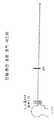
[0017]도 2는 일 실시예에 따른 단일-평면 초점 고정-거리 광학 시스템의 초점 평면을 도시한 도면이다.
[0018]도 3 및 4는 2개의 실시예들에 따른 단일-평면 초점 고정-거리 광학 시스템들의 사용자의 개개의 시야들의 개략도들이다.
[0019]도 5는 일 실시예에 따른 광학 시스템의 상세한 개략도이다.
[0020]도 6은 일 실시예에 따른 광학 시스템의 광-안내 광학 엘리먼트의 상세한 개략도이다.
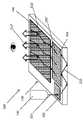
[0021]도 7은 일 실시예에 따른 광학 시스템의 광-안내 광학 엘리먼트의 상세한 사시도이다.
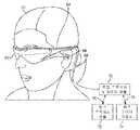
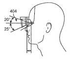
[0022]도 8a 내지 8d 및 9a 내지 9d는 다양한 실시예들에 따른 증강 현실/사용자 식별 시스템들의 개략도들이다.
[0023]도 10은 다중-평면 초점 풀 증강 현실 시스템의 상세한 개략도이다.
[0024]도 11 및 12는 2개의 실시예들에 따른 단일-평면 초점 고정-거리 증강 현실 시스템들의 상세한 개략도들이다.
[0025]도 13은 일 실시예에 따른 단일-평면 초점 고정-거리 증강 현실 시스템의 사용자의 시야를 예시한다.
[0026]도 14는, 사용자의 머리를 사용자의 신체를 기준으로(relative to) 회전한 후, 도 13에 도시된 실시예에 따른 단일-평면 초점 고정-거리 증강 현실 시스템의 사용자의 시야를 예시한다.
[0027]도 15 및 16은 2개의 실시예들에 따른 단일-평면 초점 고정-거리 증강 현실 시스템의 사용자에게 가상 객체를 신체-중심 방식으로 디스플레이하기 위한 방법들을 도시하는 흐름도들이다.[0015] The drawings illustrate the design and utilization of various embodiments of the present invention. It should be noted that the drawings are not drawn to scale and elements of like structures or functions are represented by like reference numbers throughout the drawings. For a better appreciation of how the above-mentioned and other advantages and objects of various embodiments of the present invention are achieved, a more detailed description of the present inventions outlined above is illustrated in the accompanying drawings, in which a specific embodiment of the present invention is illustrated. will be provided with reference to. With the understanding that these drawings merely illustrate typical embodiments of the invention, and are therefore not to be regarded as limiting the scope of the invention, the invention may be brought to additional specificity and detail through the use of the appended drawings. will be explained and described.
[0016] FIG. 1 is a diagram illustrating focal planes of a multi-plane focus full optical system.
[0017] Figure 2 is a diagram illustrating a focal plane of a single-plane focal fixed-distance optical system according to one embodiment.
[0018] Figures 3 and 4 are schematic diagrams of individual fields of view of a user of single-plane focal fixed-distance optical systems according to two embodiments.
[0019] Figure 5 is a detailed schematic diagram of an optical system according to one embodiment.
[0020] Figure 6 is a detailed schematic diagram of a light-guiding optical element of an optical system according to one embodiment.
[0021] Figure 7 is a detailed perspective view of a light-guiding optical element of an optical system according to one embodiment.
[0022] Figures 8a-8d and 9a-9d are schematic diagrams of augmented reality/user identification systems according to various embodiments.
[0023] Figure 10 is a detailed schematic diagram of a multi-plane focus pool augmented reality system.
[0024] Figures 11 and 12 are detailed schematic diagrams of single-plane focal fixed-distance augmented reality systems according to two embodiments.
[0025] Figure 13 illustrates a user's field of view of a single-plane focal fixed-distance augmented reality system according to one embodiment.
[0026] FIG. 14 illustrates a user's field of view of a single-plane focal fixed-distance augmented reality system according to the embodiment shown in FIG. 13 after rotating the user's head relative to the user's body. do.
[0027] Figures 15 and 16 are flow charts illustrating methods for displaying a virtual object in a body-centric manner to a user of a single-plane focal fixed-distance augmented reality system according to two embodiments.
[0028]본 발명의 다양한 실시예들은 단일 실시예 또는 다수의 실시예들에서 고정-거리 혼합형 현실 광학 시스템들을 구현하기 위한 시스템들, 방법들 및 제조 물품들에 관한 것이다. 본 발명의 다른 목적들, 특징들 및 이점들은 상세한 설명, 도면들 및 청구항들에서 설명된다.[0028]Various embodiments of the present invention are directed to systems, methods and articles of manufacture for implementing fixed-range mixed reality optical systems in a single embodiment or multiple embodiments. Other objects, features and advantages of the present invention are set forth in the detailed description, drawings and claims.
[0029]당업자들이 본 발명을 실시하는 것을 가능하게 하도록 본 발명의 예시적인 예들로서 제공되는 도면들을 참조하여 다양한 실시예들이 이제 상세하게 설명될 것이다. 특히, 이하의 도면들 및 예들은 본 발명의 범위를 제한하는 것으로 의도되지 않는다. 본 발명의 소정의 엘리먼트들이 알려진 컴포넌트들(또는 방법들 또는 프로세스들)을 사용하여 부분적으로 또는 완전히 구현될 수 있는 경우, 본 발명의 이해에 필수적인 그러한 알려진 컴포넌트들(또는 방법들 또는 프로세스들)의 부분들만이 설명될 것이며, 그러한 알려진 컴포넌트들(또는 방법들 또는 프로세스들)의 다른 부분들의 상세한 설명들은 본 발명을 모호하게 하지 않기 위해 생략될 것이다. 또한, 다양한 실시예들은 예시로 본원에서 언급된 컴포넌트들에 대한 현재 알려진 등가물들 및 미래에 알려질 등가물들을 포함한다.[0029]Various embodiments will now be described in detail with reference to the drawings, which are provided as illustrative examples of the present invention to enable those skilled in the art to practice the present invention. In particular, the following figures and examples are not intended to limit the scope of the invention. Where certain elements of the invention can be partially or fully implemented using known components (or methods or processes), those known components (or methods or processes) essential to an understanding of the invention. Only parts will be described, and detailed descriptions of other parts of such known components (or methods or processes) will be omitted so as not to obscure the present invention. Further, various embodiments include currently known equivalents and future known equivalents to the components mentioned herein by way of example.
[0030]광학 시스템들은 AR/MR 시스템들과 독립적으로 구현될 수 있지만, 이하의 다수의 실시예들은 단지 예시 목적들을 위해 AR/MR 시스템들과 관련하여 설명된다.[0030]Although the optical systems can be implemented independently of AR/MR systems, several embodiments below are described with respect to AR/MR systems for illustrative purposes only.
문제 및 해결책의 요약Summary of problems and solutions
[0031]다양한 깊이들에 가상 이미지들을 생성하기 위한 하나의 타입의 광학 시스템은, 3-D 경험/시나리오의 품질(예컨대, 이미징 평면들의 수) 및 이미지들의 품질(예컨대, 이미지 컬러들의 수)이 향상됨에 따라, 수가 증가하고, 이로써 VR/AR/MR 시스템들의 복잡성, 사이즈 및 비용을 증가시키는 다수의 광학 컴포넌트들(예컨대, 광 소스들, 프리즘들, 격자들, 필터들, 스캔-광학기기, 빔 분할기들, 미러들, 하프-미러들, 셔터들, 접안 렌즈들 등)을 포함한다. 3-D 시나리오/이미지 품질의 향상과 함께 광학 시스템들의 사이즈의 증가는 VR/AR/MR 시스템들의 최소 사이즈에 대해 제한을 부과하고 이는 광학 효율성이 감소된 다루기 어려운 시스템들을 초래한다.[0031]One type of optical system for creating virtual images at various depths can be used as the quality of the 3-D experience/scenario (eg number of imaging planes) and quality of images (eg number of image colors) improves. , a number of optical components (e.g., light sources, prisms, gratings, filters, scan-optics, beamsplitters) that increase in number, thereby increasing the complexity, size and cost of VR/AR/MR systems. , mirrors, half-mirrors, shutters, eyepieces, etc.). The increase in the size of optical systems along with the improvement of 3-D scenario/image quality imposes a limitation on the minimum size of VR/AR/MR systems, which results in unwieldy systems with reduced optical efficiency.
[0032]다음 개시내용은 광학 시스템들에 더 적은 컴포넌트들 및 증가된 효율성을 제공함으로써, 문제를 해결하는, 각각의 눈에 대해 단일-평면 초점 광학 엘리먼트들을 사용하여 단일의 미리 결정된 거리 주위에 3-D 인식을 생성하기 위한 시스템들 및 방법들의 다양한 실시예들을 설명한다. 특히, 본원에 설명된 시스템들은, 혼합형 현실 시나리오들에에 대해 사용자로부터 미리 결정된 거리에 가상 객체들을 디스플레이하기 위한 광학 시스템을 제공하기 위해 최소 세트의 광학 시스템 컴포넌트들을 활용한다. 이러한 광학 시스템 설계는, 미리 결정된 거리에 가상 객체들을 디스플레이하기 위한 그러한 시스템들의 기능을 제한함으로써 VR/AR/MR 시스템들의 사이즈를 간략화 및 감소시킨다.[0032]The following disclosure addresses the problem of 3-D perception around a single predetermined distance using single-planar focusing optical elements for each eye, by providing optical systems with fewer components and increased efficiency. Various embodiments of systems and methods for generating In particular, the systems described herein utilize a minimal set of optical system components to provide an optical system for displaying virtual objects at a predetermined distance from a user for mixed reality scenarios. This optical system design simplifies and reduces the size of VR/AR/MR systems by limiting the ability of such systems to display virtual objects at a predetermined distance.
풀 증강 현실 시스템들full augmented reality systems
[0033]고정-거리 혼합형 현실 광학 시스템들의 실시예들의 세부사항들을 설명하기 전에, 본 개시내용은, 가상 객체들이 사용자의 광학 축을 따라(예컨대, 무한대로부터 인접한 사용자로) 복수의 위치들에서 나타나는 풀 AR 시나리오를 제공하도록 구성된 관련된 풀 AR/MR 시스템들의 짧은 설명을 이제 제공할 것이다. 혼합형 현실 광학 시스템들(풀 및/또는 고정-거리)은 AR/MR 시스템들과 독립적으로 구현될 수 있지만, 이하의 많은 시스템들은 단지 예시 목적들로 AR/MR 시스템들에 관련하여 설명된다. 다양한 증강 현실 디스플레이 시스템들은 대리인 문서 번호 ML_30011-US 하에서 2014년 11월 27일로 출원되고 발명의 명칭이 "VIRTUAL AND AUGMENTED REALITY SYSTEMS AND METHODS"인 공동 소유의 미국 특허 출원 일련 번호 제14/555,585호에 논의되었고, 그로 인해 상기 출원의 내용들은 마치 빠짐없이 기술된 것처럼 그 전체가 인용에 의해 명시적으로 그리고 완전히 본원에 포함된다.[0033]Before describing the details of embodiments of fixed-distance mixed reality optical systems, the present disclosure describes a full AR scenario in which virtual objects appear at multiple locations along a user's optical axis (eg, from infinity to a nearby user). A brief description of related full AR/MR systems configured to provide will now be given. Although mixed reality optical systems (full and/or fixed-distance) may be implemented independently of AR/MR systems, many of the systems below are described in relation to AR/MR systems for illustrative purposes only. Various augmented reality display systems are discussed in commonly owned U.S. Patent Application Serial No. 14/555,585, filed on November 27, 2014, entitled "VIRTUAL AND AUGMENTED REALITY SYSTEMS AND METHODS" under Attorney Docket No. ML_30011-US. is hereby expressly and fully incorporated herein by reference in its entirety as if set forth in its entirety.
[0034]풀 AR/MR 시스템을 구현하기 위한 하나의 가능한 접근법은, 사용자의 각각의 눈에 대해, 개별 깊이 평면들로부터 발생하는 것으로 보이는 이미지들을 생성하기 위하여 깊이 평면 정보가 임베딩된 복수의 볼륨 위상 홀로그램들, 표면-양각(relief) 홀로그램들, 또는 "LOE(light-guiding optical elements)"를 사용한다. 다시 말해서, 회절 패턴, 또는 "DOE(diffractive optical element)"는, 시준된 광(실질적으로 평면 파면들을 가진 광 빔들)이 LOE를 따라 실질적으로 내부 전반사됨에 따라, 시준된 광이 다수의 위치들에서 회절 패턴과 교차하고 사용자의 눈을 향하여 적어도 부분적으로 퇴장하도록, LOE 내에 임베딩되거나 LOE 상에 임프린트(imprint)될 수 있다. DOE들은, LOE로부터 DOE를 통해 퇴장하는 광이 기울어져서(verged) 퇴장하는 광이 특정 깊이 평면으로부터 발생하는 것으로 보이도록 구성된다. 시준된 광은 광학 집광 렌즈("집광기")를 사용하여 생성될 수 있다.[0034]One possible approach for implementing a full AR/MR system is, for each eye of a user, a plurality of volume phase holograms with embedded depth plane information to create images that appear to arise from separate depth planes; It uses surface-relief holograms, or “light-guiding optical elements” (LOEs). In other words, a diffraction pattern, or "diffractive optical element" (DOE), is formed when collimated light (light beams with substantially planar wavefronts) is substantially totally internally reflected along the LOE, so that collimated light is reflected at multiple locations. It can be embedded in or imprinted on the LOE, such that it intersects the diffraction pattern and exits at least partially towards the eye of the user. The DOEs are configured so that light exiting from the LOE through the DOE is verged so that the exiting light appears to originate from a particular depth plane. Collimated light may be produced using an optical condensing lens ("concentrator").
[0035]예컨대, 제1 LOE는 광학 무한대 깊이 평면(0 디옵터)으로부터 발생하는 것으로 보이는 시준된 광을 눈으로 전달하도록 구성될 수 있다. 다른 LOE는 2 미터의 거리(1/2 디옵터)로부터 발생하는 것으로 보이는 시준된 광을 전달하도록 구성될 수 있다. 또 다른 LOE는 1 미터의 거리(1 디옵터)로부터 발생하는 것으로 보이는 시준된 광을 전달하도록 구성될 수 있다. 스택된 LOE 조립체를 사용함으로써, 다수의 깊이 평면들이 생성될 수 있다는 것이 인식될 수 있고, 각각의 LOE는 특정 깊이 평면으로부터 발생하는 것으로 보이는 이미지들을 디스플레이하도록 구성된다. 스택이 임의의 수의 LOE들을 포함할 수 있다는 것이 인식되어야 한다. 그러나, 적어도 N개의 스택된 LOE들은 N개의 깊이 평면들을 생성하기 위하여 요구된다. 게다가, N개, 2N개 또는 3N개의 스택된 LOE들은 N개의 깊이 평면들에서 RGB 컬러 이미지들을 생성하는 데 사용될 수 있다.[0035]For example, the first LOE may be configured to deliver collimated light that appears to originate from the optical infinity depth plane (0 diopters) to the eye. Other LOEs may be configured to deliver collimated light that appears to originate from a distance of 2 meters (½ diopter). Another LOE can be configured to deliver collimated light that appears to originate from a distance of 1 meter (1 diopter). It can be appreciated that by using a stacked LOE assembly, multiple depth planes can be created, each LOE configured to display images that appear to originate from a particular depth plane. It should be appreciated that a stack may contain any number of LOEs. However, at least N stacked LOEs are required to create N depth planes. Moreover, N, 2N or 3N stacked LOEs may be used to create RGB color images in N depth planes.
[0036]풀 3-D AR 시나리오에서 가상 콘텐츠를 사용자에게 제시하기 위하여, 풀 AR/MR 시스템은, 가상 콘텐츠의 이미지들이 Z 방향(즉, 사용자의 눈으로부터 직각으로 멀어짐)의 다양한 깊이 평면들로부터 발생하는 것으로 보이도록 그 가상 콘텐츠의 이미지들을 사용자의 눈으로 투사한다. 다른 말로, 가상 콘텐츠는 X 및 Y 방향들(즉, 사용자의 눈의 중심 시각 축에 직각의 8D 평면)에서 변화할 수 있을 뿐 아니라, 사용자가 객체를 매우 가깝게 있는 것으로 또는 무한대 거리에 있는 것으로 또는 그 사이의 임의의 거리에 있는 것으로 인식할 수 있도록 가상 콘텐츠가 또한 Z 방향으로 변화하는 것으로 보일 수 있다. 풀 AR/MR 시스템들에서, 사용자는 상이한 깊이 평면들에 있는 다수의 객체들을 동시에 인식할 수 있다. 예컨대, 사용자는 가상 용이 무한대로부터 나타나서 사용자를 향해 달려오는 것을 볼 수 있다. 대안적으로, 사용자는 사용자로부터 3 미터 떨어진 거리에 있는 가상 새 및 사용자로부터 팔의 길이(약 1 미터)에 있는 가상 커피 컵을 동시에 볼 수 있다.[0036]To present virtual content to a user in a full 3-D AR scenario, a full AR/MR system assumes that images of the virtual content originate from various depth planes in the Z direction (i.e., perpendicularly away from the user's eyes). Images of the virtual content are projected onto the user's eyes so that they can be seen. In other words, the virtual content can change in the X and Y directions (i.e., in the 8D plane perpendicular to the central visual axis of the user's eyes), as well as allowing the user to move objects as very close or at infinite distances or The virtual content may also appear to change in the Z direction so that it can be perceived as being any distance in between. In full AR/MR systems, a user can simultaneously perceive multiple objects in different depth planes. For example, the user may see a virtual dragon emerge from infinity and run towards the user. Alternatively, the user may simultaneously see a virtual bird at a distance of 3 meters from the user and a virtual coffee cup at arm's length (approximately 1 meter) from the user.
[0037]다중-평면 초점 풀 AR/MR 시스템들은 사용자의 눈으로부터 Z 방향으로 개별 고정된 거리들에 위치된 복수의 깊이 평면들 중 일부 또는 모두에 이미지들을 투사함으로써 가변 깊이의 인식을 생성한다. 이제 도 1을 참조하여, 다중-평면 초점 풀 AR/MR 시스템들은 통상적으로 고정된 깊이 평면들(202)(예컨대, 도 1에 도시된 6개의 깊이 평면들(202))에 프레임들을 디스플레이하는 것이 인식되어야 한다. 하나의 예시적인 다중-평면 초점 풀 AR/MR 시스템은 Z 방향으로 6개의 고정된 깊이 평면들(202)을 가진다. 6개의 깊이 평면들(202) 중 하나 이상에 가상 콘텐츠를 생성할 때, 사용자가 사용자의 눈으로부터 다양한 거리들에 있는 하나 이상의 가상 객체들을 인식하도록 3-D 인식이 생성된다. 인간 눈이 더 멀리 떨어진 것으로 보이는 객체들보다 거리가 더 가까운 객체들에 더 민감하다는 것을 고려할 때, 도 1에 도시된 바와 같이, 더 많은 깊이 평면들(202)이 눈에 더 가깝게 생성된다. 다른 시스템들에서, 깊이 평면들(202)은 서로 동일한 거리들로 떨어져 배치될 수 있다.[0037]Multi-plane focus full AR/MR systems create the perception of variable depth by projecting images onto some or all of a plurality of depth planes located at discrete fixed distances in the Z direction from the user's eye. Referring now to FIG. 1 , multi-plane focus full AR/MR systems typically display frames in fixed depth planes 202 (eg, the six
[0038]깊이 평면 포지션들(202)은 통상적으로 디옵터로 측정되고, 디옵터는 미터로 측정된 초점 길이의 역과 동일한 광학력(optical power)의 단위이다. 예컨대, 일 시스템에서, 깊이 평면(1)은 1/3 디옵터 떨어질 수 있고, 깊이 평면(2)은 0.3 디옵터 떨어질 수 있고, 깊이 평면(3)은 0.2 디옵터 떨어질 수 있고, 깊이 평면(4)은 0.15 디옵터 떨어질 수 있고, 깊이 평면(5)은 0.1 디옵터 떨어질 수 있고, 그리고 깊이 평면(6)은 무한대(즉, 0 디옵터 떨어짐)를 나타낼 수 있다. 다른 시스템들이 다른 거리들/디옵터들의 깊이 평면들(202)을 생성할 수 있다는 것이 인식되어야 한다. 따라서, 전략적으로 배치된 깊이 평면들(202)에 가상 콘텐츠를 생성할 때, 사용자는 가상 객체들을 3차원들로 인식할 수 있다. 예컨대, 사용자는 깊이 평면(1)에 디스플레이될 때 제1 가상 객체를 자신에게 가깝게 있는 것으로 인식할 수 있지만, 다른 가상 객체는 깊이 평면(6)에서 무한대로 보인다. 대안적으로, 가상 객체는, 가상 객체가 사용자에게 매우 가깝게 보일 때까지 먼저 깊이 평면(6)에 디스플레이되고, 이어서 깊이 평면(5)에 디스플레이되는 식일 수 있다. 위의 예들이 예시 목적들을 위해 상당히 단순화된 것이 인식되어야 한다. 다른 시스템에서, 모두 6개의 깊이 평면들은 사용자로부터 특정 초점 거리 떨어져 집중될 수 있다. 예컨대, 디스플레이될 가상 콘텐츠가 사용자로부터 1/2미터 떨어진 커피 컵이면, 커피 컵의 다양한 단면들에서 모두 6개의 깊이 평면들이 생성될 수 있고, 이는 사용자에게 커피 컵의 고도로 입체화된 3-D 뷰(view)를 제공한다.[0038]Depth plane positions 202 are typically measured in diopters, where a diopter is a unit of optical power equal to the reciprocal of the focal length measured in meters. For example, in one system,
[0039]일 시스템에서, 풀 AR/MR 시스템은 다중-평면 초점 시스템으로서 작동할 수 있다. 다른 말로, 모두 6개의 LOE들은 동시에 조명될 수 있어서, 6개의 고정된 깊이 평면들로부터 발생하는 것으로 보이는 이미지들은, 광 소스들이 이미지 정보를 LOE 1, 이어서 LOE 2, 이어서 LOE 3과 같은 식으로 빠르게 전달하여 빠르고 연속적으로 생성된다. 예컨대, 광학 무한대에 있는 하늘의 이미지를 포함하는 원하는 이미지의 일부는 시간(1)에서 주입될 수 있고 광의 시준을 유지하는 LOE(1090)(예컨대, 도 1의 깊이 평면(6))가 활용될 수 있다. 이어서 더 가까운 나무 가지의 이미지는 시간(2)에서 주입될 수 있고, 10 미터 떨어진 깊이 평면(예컨대, 도 1로부터의 깊이 평면(5))으로부터 발생하는 것으로 보이는 이미지를 생성하도록 구성된 LOE(1090)가 활용될 수 있고; 이어서 펜의 이미지가 시간(3)에서 주입될 수 있고, 1 미터 떨어진 깊이 평면으로부터 발생하는 것으로 보이는 이미지를 생성하도록 구성된 LOE(1090)가 활용될 수 있다. 이런 타입의 패러다임은, 사용자의 눈 및 뇌(예컨대, 시각 피질(cortex))이 입력을 모두 동일 이미지의 부분인 것으로 인식하도록 빠른 시간 순차적(예컨대, 360 Hz) 방식으로 반복될 수 있다.[0039]In one system, a full AR/MR system can operate as a multi-plane focus system. In other words, all six LOEs can be illuminated simultaneously, so that images that appear to originate from six fixed depth planes, the light sources quickly convert image information to
[0040]풀 AR/MR 시스템들은 풀 3-D 경험을 위한 이미지들을 생성하기 위하여 Z 축(즉, 깊이 평면들)을 따라 다양한 위치들로부터 발생하는 것으로 보이는 이미지들을 투사(즉, 광 빔들을 발산시키거나(diverging) 또는 수렴시킴으로써)하도록 요구받는다. 본 출원에 사용된 바와 같이, "광 빔들"은 광 소스로부터 방출되는 광 에너지(가시광 에너지 및 비가시광 에너지를 포함함)의 지향성 투사들(그러나 이에 제한되지 않음)을 포함한다. 다양한 깊이 평면들로부터 발생하는 것으로 보이는 이미지들을 생성하는 것은 그 이미지에 대한 사용자의 눈의 이접운동과 원근조절을 따르거나 동기화하고, 그리고 이접운동-원근조절 충돌을 최소화하거나 제거한다.[0040]Full AR/MR systems project (i.e., diverge light beams) or project images that appear to originate from various locations along the Z axis (i.e., depth planes) to create images for a full 3-D experience. by diverging) or converging). As used herein, “light beams” includes (but is not limited to) directed projections of light energy (including visible and invisible light energy) emitted from a light source. Generating images that appear to originate from the various depth planes follows or synchronizes the user's eye vergence and accommodation for that image, and minimizes or eliminates the vergence-accommodation conflict.
[0041]다양한 깊이 평면들로부터 발생된 것처럼 보이는 이미지들을 투사하기 위한 풀 AR 시나리오 기능 요건은 풀 AR/MR 시스템들에 최소의 복잡성, 사이즈 및 비용 제한들을 부여한다. 본원에 설명된 고정-거리 AR/MR 시스템들은 시스템의 기능을 감소시킴으로써 이러한 제한들을 피한다.[0041]The full AR scenario functional requirement for projecting images that appear to originate from various depth planes places minimal complexity, size and cost limitations on full AR/MR systems. The fixed-range AR/MR systems described herein circumvent these limitations by reducing the functionality of the system.
고정-거리 증강 현실 시스템들Fixed-distance augmented reality systems
[0042]고정-거리 AR/MR 시스템들은 부분적인 AR 경험/시나리오에 대해 사용자로부터 Z 방향으로 떨어져 있는 단일의 미리 결정된 거리(즉, "깊이 평면") 근처/인접하게 (즉, 이로부터 약 0.2 디옵터 내지 약 0.6 디옵터 내의) 가상 객체들을 디스플레이하도록 구성된다. 이제 도 2를 참조하면, 단일-평면 초점 고정-거리 AR/MR 시스템들이 통상적으로 하나의 고정된 깊이 평면(202)에서 프레임들을 디스플레이한다는 것이 인지되어야 한다. 고정-거리 AR/MR 시스템의 사용자에 대한 시각 효과는, 사용자의 전방에 그리고 사용자를 중심으로, 디스플레이된 이미지들의 가상 돔(virtual dome)이 사용자에게 제공된다는 것이다. 돔(206)은 도 3에서 2-D 아크로 표현되고, 여기서 디스플레이된 이미지들의 가상 돔(206)은 사용자의 전방에 있다. 사용자가 약 50°의 고정적인 좌우 시야("FOV")(208)를 가질 수 있지만, 유효 L/R FOV는, 도 3에 도시된 바와 같이, "신체-중심" 시스템(아래에 설명됨)에서의 머리 회전으로 인해 약 180°가 될 것이다. 또한, 사용자의 FOV는 상하 머리 움직임으로 전체 돔(206)을 커버할 수 있다. 따라서, 고정-거리 AR/MR 시스템은, 사용자(204)를 둘러싸는 전체 돔(206)에 걸쳐 사용자에게 이미지 정보를 제공할 수 있다. 고정 사용자가 신체 및 머리 회전의 자유를 갖는 다른 실시예에서, 유효 FOV는, 도 4에 도시된 바와 같이, 전체 구(sphere)(209)일 수 있다. 도 3 및 4가 2-D에서 고정-거리 AR/MR 시스템에 의해 제공되는 이미지들의 돔(206) 및 구(209)를 나타내지만, 돔(206) 및 구(209)가 3차원 표면들이라는 것이 이해되어야 한다.[0042]Fixed-distance AR/MR systems are near/adjacent to (i.e., from about 0.2 diopters to about to within 0.6 diopters) of virtual objects. Referring now to FIG. 2 , it should be appreciated that single-plane focal fixed-distance AR/MR systems typically display frames in one fixed
[0043]고정-거리 AR/MR 시스템들은, 각각의 눈에 대해, 미리 결정된 깊이 평면의 허용오차 범위 내에서(예컨대, 미리 결정된 깊이 평면으로부터 약 0.2 디옵터 내지 약 0.6 디옵터 내에서) 발생되는 것처럼 보이는 이미지들을 생성하기 위해, 깊이 평면 정보가 임베딩된 단일 볼륨 위상 홀로그램(single volume phase hologram), 또는 표면-양각 홀로그램(surface-relief hologram), 또는 "LOE(light-guiding optical element)"로 구현될 수 있다. 고정-거리 AR/MR 시스템들은 입체 기술을 사용함으로써(즉, 미리 결정된 거리의 허용오차 범위 내에서 Z 방향으로 약간 다른 거리들에서 각각의 눈에 대한 개개의 이미지들을 디스플레이함으로써) 3-D 효과를 생성할 수 있다.[0043]Fixed-distance AR/MR systems produce images that, for each eye, appear to occur within a tolerance of a predetermined depth plane (e.g., within about 0.2 diopters to about 0.6 diopters from the predetermined depth plane). To do this, it may be implemented as a single volume phase hologram, a surface-relief hologram, or a "light-guiding optical element (LOE)" in which depth plane information is embedded. Fixed-distance AR/MR systems achieve a 3-D effect by using stereoscopic techniques (i.e., by displaying individual images for each eye at slightly different distances in the Z direction within a tolerance of a predetermined distance). can create
[0044]인간 시각 시스템이 이접운동에 대해 매우 정확하지만, 인간 시각 시스템은, 이접운동-원근조절 반사 작용(vergence-accommodation reflex) 관련 문제들이 발생하기 전에, 원근조절(즉, 초점)에서의 차이들에 대해 일부 허용오차를 갖는다. 특정 사용자에 대해 특정되지만, 원근조절에서 허용오차/불확실성은 통상적으로 이접운동에 대해 약 0.2 디옵터 내지 약 0.6 디옵터 사이에 발생한다. 따라서, 본원에 개시된 고정-거리 AR/MR 시스템들은, 특히, 사용자의 팔 길이를 초과하는 범위들에서, Z 방향에서 단일의 미리 결정된 거리 근처에 3-D 객체들을 디스플레이하기 위한 원근조절에서의 차이들에 대해 인간 시각 시스템의 허용오차를 이용한다.[0044]Although the human visual system is very accurate for vergence-accommodation reflexes, the human visual system is very sensitive to differences in accommodation (i.e., focus) before problems with the vergence-accommodation reflex arise. have some tolerance. Although specific to a particular user, tolerances/uncertainities in accommodation typically occur between about 0.2 diopters and about 0.6 diopters for vergence. Thus, the fixed-distance AR/MR systems disclosed herein can accommodate differences in accommodation for displaying 3-D objects near a single predetermined distance in the Z direction, particularly at ranges exceeding the user's arm length. It uses the tolerance of the human visual system for .
[0045]디옵터가 사용자의 눈(도 1 참조)으로부터의 거리의 역(inverse)이기 때문에, 디옵터들이 일정한 원근조절에서의 허용오차/불확실성은 선형 거리 측면에서 변한다. 예시 목적들로, 사용자로부터 1.00m(= 1.0 디옵터)의 제1 거리에서, 0.2 디옵터(통상적인 허용오차들의 더 낮은 범위)를 부가하는 것은 0.83m의 제2 거리, 즉, -17cm의 변화를 발생시킬 것이다. 유사하게, 반대 방향의 0.2 디옵터는, 1.00m에서 디스플레이되는 경우 콘텐츠가 0.2 디옵터의 원근조절 허용오차들 내에서 보여지기 위한 0.83m 내지 1.25m의 총 범위(즉, 고정-거리 AR/MR 시스템이 0.2 디옵터의 허용오차 내에서 1.00m에서 콘텐츠를 디스플레이하기 위한 42cm의 범위)에 대해 1.25m의 거리에 대응한다.[0045]Since diopters are the inverse of distance from the user's eye (see FIG. 1), the tolerance/uncertainty in accommodation where diopters are constant varies in terms of linear distance. For illustrative purposes, at a first distance of 1.00 m (= 1.0 diopters) from the user, adding 0.2 diopters (lower range of typical tolerances) results in a change of -17 cm at a second distance of 0.83 m. will cause Similarly, 0.2 diopters in the opposite direction, when displayed at 1.00 m, gives a total range of 0.83 m to 1.25 m for content to be viewed within accommodation tolerances of 0.2 diopters (i.e., if a fixed-distance AR/MR system is This corresponds to a distance of 1.25 m for a range of 42 cm for displaying content at 1.00 m within a tolerance of 0.2 diopters.
[0046]반면에, 사용자로부터 0.50m(= 2.0 디옵터)의 제1 거리에 대해, 0.6 디옵터를 부가하는 것은 0.38m의 제2 거리, -12cm의 변화가 발생시킬 것이다. 대응하는 0.6 디옵터를 0.50m의 제1 거리로부터 멀리 이동시키는 것은 0.71m의 거리, 즉, 21cm의 변화를 발생시키는 바, 고정 AR/MR 시스템이 0.6 디옵터의 허용오차 내에서 0.5m에서 콘텐츠를 디스플레이하기 위한 33cm의 총 범위를 발생시킨다. 0.2 디옵터 허용오차를 갖는 1.00m 고정-거리 AR/MR 시스템의 42cm 범위와 비교하여, 허용오차를 0.6(디옵터 허용오차의 다른 극한값)으로 3배 증가(tripling)시키는 것은 더 가까운 0.5m 제1 거리 시스템에 대한 콘텐츠 투사의 범위를 실제로 감소시켰다. 따라서, 더 정확한(즉, 더 낮은) 원근조절 허용오차들을 갖는 고정 거리 시스템은, 사용자로부터 더 멀리 떨어진 고정 거리들에 콘텐츠를 디스플레이하기 위한 더 큰 기능적 범위들을 가질 것이다.[0046]On the other hand, for a first distance of 0.50 m (= 2.0 diopters) from the user, adding 0.6 diopters will result in a second distance of 0.38 m, a change of -12 cm. Moving the corresponding 0.6 diopters away from the first distance of 0.50 m results in a change of 0.71 m, i.e. 21 cm, so that a fixed AR/MR system displays the content at 0.5 m within a tolerance of 0.6 diopters. resulting in a total range of 33 cm for Compared to the 42 cm range of a 1.00 m fixed-distance AR/MR system with a 0.2 diopter tolerance, tripling the tolerance to 0.6 (the other extreme of the diopter tolerance) results in a closer 0.5 m primary distance. It actually reduced the scope of content projection for the system. Thus, a fixed distance system with more accurate (ie lower) accommodation tolerances will have greater functional ranges for displaying content at fixed distances farther away from the user.
[0047]단일 광학 평면 주위에서 본 발명의 허용오차 범위들을 사용하는 고정-거리 AR/MR 시스템은, 콘텐츠가 사용자로부터 미리 결정된 광학 장소의 특정 범위들 내에서, 바람직하게는 상이한 사용자들에 걸쳐 허용오차 범위들을 최대화하기 위한 더 큰 거리들에서 나타날 때만, 그러한 콘텐츠 디스플레이/렌더링이 허용되는 경우, 기능성을 크게 간략화할 수 있다. 유사하게, 일부 실시예들에서, 특정 콘텐츠는, 고정-거리 AR/MR 시스템의 미리 결정된 광학 평면의 위치를 설정하는 광학력이 알려지거나, 사용자의 특정 바람직한 허용오차가 결정되는 경우에, 특정 범위들 내에만 나타나도록 구성될 수 있다.[0047]A fixed-distance AR/MR system using the tolerance ranges of the present invention around a single optical plane is such that the content is within specific ranges of the optical location pre-determined from the user, preferably within tolerance ranges across different users. Only appearing at larger distances to maximize can greatly simplify functionality if such content display/rendering is allowed. Similarly, in some embodiments, the specific content is within a specific range, when the optical forces that set the position of the predetermined optical plane of the fixed-distance AR/MR system are known, or the user's specific desired tolerances are determined. It can be configured to appear only within fields.
[0048]표 1은 일부 실시예들에 따른 디옵터 허용오차들 내의 콘텐츠 디스플레이를 허용하는, 사용자로부터 고정-거리에서의 미리 결정된 광학 평면에 대한 범위들을 도시한다. 표 1은, 더 큰 범위들의 콘텐츠 디스플레이를 가능하게 하는 추가의 광학 평면들과 대조적으로, 디옵터 허용오차들과 상관없이, 콘텐츠가 사용자-근처 광학 평면들(0.5m의 미리 결정된 광학 평면 거리들 참조)에 대해 디스플레이될 수 있는 타이트한 범위들을 예시한다.[0048]Table 1 shows ranges for a predetermined optical plane at a fixed-distance from the user, allowing content display within diopter tolerances according to some embodiments. Table 1 shows that, regardless of diopter tolerances, content can be placed in user-near optical planes (see pre-determined optical plane distances of 0.5m), as opposed to additional optical planes that enable larger ranges of content display. ) illustrates the tight ranges that can be displayed for

[0049]일부 실시예들에서, 고정-거리 AR/MR 시스템에 대한 허용오차 범위는 렌더링 도메인들을 설정할 수 있어서, 범위 내에서 나타나지 않는 콘텐츠가 렌더링되지 않을 것이고, 따라서 배터리 수명을 절약할 것이거나, 콘텐츠가 특히 미리 결정된 광학 평면의 허용오차들 내에 남아있기 위해 사용자로부터 특정 거리들 내에서 나타나도록 프로그래밍될 수 있다.[0049]In some embodiments, a tolerance range for a fixed-distance AR/MR system can set rendering domains so that content that does not appear within the range will not be rendered, thus saving battery life, or content that does not appear particularly It can be programmed to appear within certain distances from the user in order to remain within predetermined optical plane tolerances.
[0050]일부 실시예들에서, 사용자는 기능성(즉, 특정 거리들, 예컨대, 가상 컴퓨터 스크린 내에만 콘텐츠를 실질적으로 렌더링할 필요가 있을 고정-거리 AR 실시예를 선정하는 것)에 의해 또는 처방전(prescription)(즉, 특정 디옵터 허용오차들을 초과할 때 사용자가 불편함을 경험한다는 것을 인지하는 것)에 의해 허용오차를 선택할 수 있다. 그러한 선택은, 모든 사용 경우들을 서빙하도록 의도된 더 복잡한 AR/MR 시스템과는 대조적으로, 특정 설정에 대해 맞춤화되고 간략화된 AR 디바이스들을 선택하는 것과 유사하다.[0050]In some embodiments, a user may choose a fixed-distance AR embodiment that will need to substantially render content only within certain distances, eg, a virtual computer screen, by functionality (i.e., by functionality) or by prescription. (i.e., recognizing that the user experiences discomfort when exceeding certain diopter tolerances). Such selection is analogous to selecting AR devices that are tailored and simplified for a specific setup, as opposed to more complex AR/MR systems intended to serve all use cases.
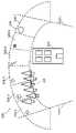
[0051]도 5는 단일 깊이 평면에 이미지들을 투사하기 위한 고정-거리 광학 시스템(100)의 부분들을 도시한다. 시스템(100)은 광 소스(120), 및 회절 광학 엘리먼트(도시되지 않음) 및 이와 연관된 인커플링 격자(192)("ICG")를 가진 LOE(190)를 포함한다. 회절 광학 엘리먼트들은 볼류메트릭(volumetric) 또는 표면 양각을 포함하는 임의의 타입을 가질 수 있다. 일 실시예에서, ICG(192)는 LOE(190)의 반사-모드 알루미늄화된 부분일 수 있다. 다른 실시예에서, ICG(192)는 LOE(190)의 투과성 회절 부분일 수 있다. 시스템(100)이 사용 중일 때, 광 소스(120)로부터의 가상 광 빔(210)은 ICG(192)를 통하여 LOE(190)에 진입하고 사용자의 눈에 디스플레이하기 위하여 실질적으로 내부 전반사("TIR")에 의해 LOE(190)를 따라 전파된다. 광 빔(210)은, 시스템(100)에 의해 지시된 바와 같이 존재하지 않는 "가상" 객체의 이미지 또는 이미지의 부분을 인코딩하기 때문에 "가상"이다. 비록 단지 하나의 빔(210)만이 도 5에 예시되지만, 이미지를 인코딩하는 다수의 빔들이 동일한 ICG(192)를 통하여 광범위한 각도들로부터 LOE(190)에 진입할 수 있다는 것이 이해된다. 진입 각도들의 범위는 시스템(100)에서 달성 가능한 FOV에 관련된다. LOE에 "진입"하거나 "허용"되는 광 빔은, 실질적으로 TIR에 의해 LOE를 따라 전파하도록 LOE와 상호작용하는 광 빔(그러나 이에 제한되지 않음)을 포함한다. 도 5에 묘사된 시스템(100)은 다양한 광 소스들(120)(예컨대, LED들, OLED들, 레이저들 및 마스킹된 광역/광대역 방출기들)을 포함할 수 있다. 다른 실시예들에서, 광 소스(120)로부터의 광은 또한 광섬유 케이블들(도시되지 않음)을 통하여 LOE(190)로 전달될 수 있다.[0051]5 shows parts of a fixed-distance
[0052]도 6에 도시된 바와 같이, 고정-거리 광학 시스템(100)의 LOE(190)의 부분은 Y 방향으로 광 소스(120)의 개구수(numerical aperture)를 증가시키기 위해 "EPE(exit pupil expander)"(196)로서 기능하고, 이로써 시스템(100)의 해상도가 증가된다. 광 소스(120)가 작은 직경/스폿(spot) 사이즈의 광을 생성하기 때문에, EPE(196)는 시스템 해상도를 증가시키기 위해 LOE(190)로부터 퇴장하는 광의 동공의 외관 사이즈(apparent size)를 확장시킨다. 시스템(100)은 X(OPE) 및 Y(EPE) 방향들 둘 모두에서 광을 확장시킬 EPE(196) 외에 "OPE"(orthogonal pupil expander: 직교 동공 확장기)(194)를 더 포함할 수 있다. EPE들(196) 및 OPE들(194)에 관한 더 세부사항들은 위에서 참조된 미국 특허 출원 일련 번호 제14/555,585호에 설명되고, 이 출원의 내용들은 인용에 의해 이미 포함되었다.[0052]As shown in FIG. 6, a portion of the
[0053]도 6은 ICG(192), OPE(194) 및 EPE(196)를 가진 LOE(190)를 도시한다. 도 6은 사용자의 눈들로부터의 뷰와 유사한 평면도로부터의 LOE(190)를 도시한다. ICG(192), OPE(194) 및 EPE(196)는 볼류메트릭 또는 표면 양각을 포함하는 임의의 타입의 DOE일 수 있다. ICG(192)는 TIR에 의한 전파를 위해 광 소스(120)로부터의 가상 광 빔(210)을 허용하도록 구성된 DOE(예컨대, 선형 격자)이다. 도 6에 묘사된 시스템(100)에서, 광 소스(120)는 LOE(190) 측면에 배치된다.[0053]6 shows
[0054]OPE(194)는, 시스템(100)을 통해 전파되는 가상 광 빔(210)이 측방향으로 90도만큼 편향되도록 측방향 평면(즉, 광 경로에 수직)으로 경사진 DOE(예컨대, 선형 격자)이다. OPE(194)는 또한 광 경로를 따라 부분적으로 투명하고 부분적으로 반사성이어서, 광 빔(210)은 다수(예컨대, 11개)의 빔릿들(210')을 형성하기 위해 부분적으로 OPE(194)를 통과한다. 묘사된 시스템(100)에서, 광 경로는 X 축을 따르고, OPE(194)는 빔릿들(210')을 Y 축쪽으로 휘도록 구성된다.[0054]
[0055]EPE(196)는, 시스템(100)을 통해 전파되는 빔릿들(210')이 사용자의 눈을 향해 Z 평면으로 90도만큼 편향되도록 Z 평면(즉, X 및 Y 방향들에 수직)으로 경사진 DOE(예컨대, 선형 격자)이다. EPE(196)는 또한 광 경로(Y 축)를 따라 부분적으로 투명하고 부분적으로 반사성이어서, 빔릿들(210')은 다수(예컨대, 7개)의 빔릿들(210')을 형성하기 위해 부분적으로 EPE(196)를 통과한다. 단지 선택 빔들(210) 및 빔릿들(210')만이 명확성을 위해 라벨링된다.[0055]
[0056]OPE(194) 및 EPE(196) 둘 모두는 또한 실세계 광(예컨대, 실세계 객체들로부터 반사됨)이 사용자의 눈들에 도달하도록 Z 방향으로 OPE(194) 및 EPE(196)를 통과하는 것을 허용하기 위해 Z 축을 따라 적어도 부분적으로 투명하다. AR/MR 시스템들(100)에 대해, ICG(192)는 Z 축을 따라 적어도 부분적으로 투명하고 또한 실세계 광을 허용하도록 Z 축을 따라 또한 적어도 부분적으로 투명하다.[0056]Both
[0057]도 7은 ICG(192), OPE(194) 및 EPE(196)를 가진 LOE(190)를 포함하는 다른 고정-거리 광학 시스템(100)을 묘사한다. 시스템(100)은 또한 가상 광 빔(210)을 ICG(192)를 통해 LOE(190)로 지향시키도록 구성된 광 소스(120)를 포함한다. 광 빔(210)은 위의 도 6에 대해 설명된 바와 같이 OPE(194) 및 EPE(196)에 의해 빔릿들(210')로 분할된다. 추가로, 빔릿들(210')이 EPE(196)를 통해 전파될 때, 이들은 또한 EPE(196)를 통해 사용자의 눈을 향해 LOE(190)를 퇴장한다. 도 7에 묘사된 시스템(100)에서, 광 소스(120)는 LOE(190)에 직교하게 배치된다. 단지 선택 빔들(210) 및 빔릿들(210')만이 명확성을 위해 라벨링된다. 고정-거리 혼합형 현실 광학 시스템들은 AR/MR 시스템들과 독립적으로 구현될 수 있지만, 본원의 많은 시스템들은 단지 예시 목적들로 AR/MR 시스템들에 관련하여 설명된다.[0057]FIG. 7 depicts another fixed-distance
[0058]이제 도 8a-8d를 참조하면, 일부 일반적인 AR/MR 시스템 컴포넌트 옵션들이 예시된다. 도 8a에 도시된 바와 같이, 머리-장착 디바이스 사용자(60)의 눈들 앞에 위치된 디스플레이 시스템(62)에 커플링된 프레임(64) 구조를 착용한 사용자(60)가 도시된다. 다음은 일반적인 AR/MR 시스템의 가능한 컴포넌트들을 설명한다. 설명된 컴포넌트들은 고정-거리 AR/MR 시스템을 구현하는 데 모두 필요한 것은 아니다.[0058]Referring now to FIGS. 8A-8D , some general AR/MR system component options are illustrated. As shown in FIG. 8A , a
[0059]고정-거리 AR/MR 시스템을 구현하기 위해 필요로 되지 않지만, 스피커(66)는 도시된 구성에서 프레임(64)에 커플링되고, 사용자(60)의 외이도(ear canal)에 인접하게 위치될 수 있다. 대안적인 실시예에서, 다른 스피커(도시되지 않음)는, 입체/성형 가능한 사운드 제어를 제공하기 위해 사용자(60)의 다른 외이도에 인접하게 위치된다. 하나 이상의 실시예들에서, 고정-거리 AR/MR 시스템은 디스플레이(62)를 가질 수 있고, 디스플레이(62)는 로컬 프로세싱 및 데이터 모듈(70)에 이를테면 유선 리드 또는 무선 연결에 의해 동작 가능하게 커플링되고, 로컬 프로세싱 및 데이터 모듈(70)은 다양한 구성들로 장착될 수 있고, 이를테면, 프레임(64)에 고정식으로 부착되거나, 도 8b에 도시된 실시예에 도시된 바와 같이 헬멧 또는 모자(80)에 고정식으로 부착되거나, 헤드폰들에 임베딩되거나, 도 8c의 실시예에 도시된 바와 같이 백팩-스타일 구성으로 사용자(60)의 몸통(82)에 제거 가능하게 부착되거나, 또는 도 8d의 실시예에 도시된 바와 같이 벨트-커플링 스타일 구성으로 사용자(60)의 엉덩이(84)에 제거 가능하게 부착될 수 있다..[0059]Although not required to implement a fixed-distance AR/MR system,
[0060]로컬 프로세싱 및 데이터 모듈(70)은 전력-효율적인 프로세서 또는 제어기뿐만 아니라 디지털 메모리, 이를테면, 플래시 메모리를 포함할 수 있고, 이들 둘 모두는 데이터의 프로세싱, 캐싱 및 저장을 돕기 위해 활용될 수 있다. 데이터는 프레임(64)에 동작 가능하게 커플링될 수 있는 센서들, 이를테면, 이미지 캡처 디바이스들(이를테면, 카메라들), 및 관성 측정 유닛들(가속도계들 및 자이로스코프들을 포함함)로부터 캡처될 수 있다. 고정-거리 AR/MR 시스템을 구현하기 위해 필요로 되지 않는 선택적인 센서들은 컴퍼스들, 마이크로폰들, GPS 유닛들 및 라디오 디바이스들을 포함한다. 대안적으로 또는 부가적으로, 데이터는, 가능하게는 원격 프로세싱 모듈(72) 및/또는 원격 데이터 저장소(74)를 사용하여 획득 및/또는 프로세싱될 수 있고, 이러한 프로세싱 또는 리트리벌(retrieval) 후에 디스플레이(62)로 전달될 수 있다. 로컬 프로세싱 및 데이터 모듈(70)은, 이를테면, 유선 또는 무선 통신 링크들을 통해 원격 프로세싱 모듈(72) 및 원격 데이터 저장소(74)에 동작 가능하게 커플링(76, 78)될 수 있어서, 이러한 원격 모듈들(72, 74)은 서로 동작가능 하게 커플링되고, 로컬 프로세싱 및 데이터 모듈(70)에 대한 자원들로서 이용 가능하다.[0060]Local processing and
[0061]일 실시예에서, 원격 프로세싱 모듈(72)은 데이터 및/또는 이미지 정보를 분석하고 프로세싱하도록 구성된 하나 이상의 상대적으로 강력한 프로세서들 또는 제어기들을 포함할 수 있다. 일 실시예에서, 원격 데이터 저장소(74)는, 인터넷 또는 "클라우드" 자원 구성의 다른 네트워킹 구성을 통해 이용 가능할 수 있는 비교적 대규모의 디지털 데이터 저장 설비를 포함할 수 있다. 일 실시예에서, 로컬 프로세싱 및 데이터 모듈에서 모든 데이터가 저장되고 모든 계산이 수행될 수 있어, 임의의 원격 모듈들로부터의 완전히 자율적인 사용을 허용한다.[0061]In one embodiment,
[0062]하나 이상의 실시예들에서, 도 8a-8d에 도시된 것과 유사한 머리-착용 고정-거리 AR/MR 시스템은 사용자로부터 미리 결정된 거리의 허용오차 범위 내에서 사용자에게 가상 이미지들을 디스플레이하는 데 사용될 수 있다. 아래에 설명되는 다수의 실시예들이 머리-착용 시스템들에서 구현될 수 있지만, 다른 실시예들이 고정 디바이스들에서 구현될 수 있음이 인지되어야 한다. 예시 목적들로, 본 개시내용은 주로 머리-착용 고정-거리 AR/MR 시스템에 초점을 맞출 것이지만, 동일한 원리들이 비-머리 착용 및 비-AR 실시예들에도 물론 적용될 수 있다는 것이 인지되어야 한다.[0062]In one or more embodiments, a head-worn fixed-distance AR/MR system similar to that shown in FIGS. 8A-8D may be used to display virtual images to a user within a tolerance of a predetermined distance from the user. Although many of the embodiments described below may be implemented in head-worn systems, it should be appreciated that other embodiments may be implemented in securing devices. For illustrative purposes, this disclosure will primarily focus on head-worn, fixed-distance AR/MR systems, but it should be appreciated that the same principles can of course be applied to non-head-worn and non-AR embodiments.
[0063]하나 이상의 실시예들에서, 고정-거리 AR/MR 시스템은 통상적으로 특정 사용자의 머리에 맞춰지고, 광학 컴포넌트들이 사용자의 눈들에 정렬된다. 이러한 구성 단계들은, 어떠한 생리학적 부작용들, 이를테면, 두통들, 구역질, 불편함 등을 발생시키지 않고서, 최적의 증강 현실 경험이 사용자에게 제공되는 것을 보장하기 위해 사용될 수 있다. 따라서, 하나 이상의 실시예들에서, 사용자-착용 고정-거리 AR/MR 시스템은 각각의 개별 사용자에 대해 (물리적으로 뿐만 아니라 디지털적으로) 구성되고, 프로그램들의 세트는 사용자에 대해 특별하게 교정될 수 있다. 다른 시나리오들에서, 느슨한 맞춤 AR 디바이스는 다양한 사용자들에 의해 편안하게 사용될 수 있다. 예컨대, 일부 실시예들에서, 사용자 착용 고정-거리 AR/MR 시스템은 사용자의 눈들 사이의 거리, 머리 착용 디스플레이와 사용자의 눈들 사이의 거리, 및 사용자의 이마의 곡률을 알고 있다. 이러한 모든 측정치들은 정해진 사용자에게 맞도록 맞춤화된 머리 착용 고정-거리 AR/MR 시스템을 제공하는 데 사용될 수 있다. 다른 실시예들에서, 이러한 측정치들은 AR 디스플레이 기능들을 수행하기 위해 필요하지 않을 수 있다.[0063]In one or more embodiments, a fixed-distance AR/MR system is typically fitted to a particular user's head, with optical components aligned to the user's eyes. These configuration steps can be used to ensure that an optimal augmented reality experience is provided to the user without generating any physiological side effects, such as headaches, nausea, discomfort, and the like. Thus, in one or more embodiments, a user-worn fixed-distance AR/MR system is configured (physically as well as digitally) for each individual user, and the set of programs can be calibrated specifically for the user. have. In other scenarios, a loose fit AR device can be comfortably used by a variety of users. For example, in some embodiments, the user-worn fixed-distance AR/MR system knows the distance between the user's eyes, the distance between the head-worn display and the user's eyes, and the curvature of the user's forehead. All of these measurements can be used to provide a head-worn, fixed-range AR/MR system tailored to a given user. In other embodiments, these measurements may not be needed to perform AR display functions.
[0064]예컨대, 도 9a-9d를 참조하면, 고정-거리 AR/MR 시스템은 각각의 사용자에 대해 맞춤화될 수 있다. 도 9a에 도시된 바와 같이, 하나 이상의 실시예들에서, 머리-장착 사용자-착용 사용자 식별 시스템을 맞출 때, 사용자의 머리 형상(402)이 고려될 수 있다. 마찬가지로, 도 9b에 도시된 바와 같이, 눈 컴포넌트들(404)(예컨대, 광학기기, 광학기기를 위한 구조 등)은 수평뿐만 아니라 수직으로 사용자의 편안함을 위해 회전되거나 조정될 수 있거나, 또는 사용자의 편안함을 위해 회전될 수 있다. 하나 이상의 실시예들에서, 도 9c에 도시된 바와 같이, 사용자의 머리를 기준으로 머리 세트의 회전 지점은 사용자의 머리의 구조에 기반하여 조정될 수 있다. 유사하게, 도 9d에 도시된 바와 같이, IPD(inter-pupillary distance)(즉, 사용자의 눈들 사이의 거리)가 보상될 수 있다.[0064]For example, referring to FIGS. 9A-9D , a fixed-distance AR/MR system can be customized for each user. As shown in FIG. 9A , in one or more embodiments, a user's
[0065]이제 도 10을 참조하면, 예시적인 풀 AR/MR 시스템의 다양한 컴포넌트들이 설명될 것이다. 고정-거리 AR/MR 시스템이 풀 AR/MR 시스템보다 더 적은 컴포넌트들을 가질 것이라는 것이 인지되어야 한다. 그러나, 예시적인 풀 AR/MR 시스템을 설명하는 것은 고정-거리 AR/MR 시스템의 컴포넌트들의 상호연결들 및 기능들을 예시할 것이다. 도 10은 AR/MR 시스템 또는 AR 디바이스의 다양한 컴포넌트들의 기본 아이디어를 제공한다. 도 10은 예시 목적들로 머리 장착 AR/MR 시스템(62)의 간략화된 버전을 블록도로 우측에 도시한다.[0065]Referring now to FIG. 10 , various components of an exemplary full AR/MR system will be described. It should be appreciated that a fixed-distance AR/MR system will have fewer components than a full AR/MR system. However, describing an exemplary full AR/MR system will illustrate the functions and interconnections of components of a fixed-range AR/MR system. 10 gives a basic idea of the various components of an AR/MR system or AR device. 10 shows a simplified version of a head mounted AR/
[0066]도 10을 참조하면, 하우징 또는 프레임(108)에 의해 사용자의 머리 또는 눈들에 장착될 수 있는 디스플레이 렌즈(106)를 포함하는 적절한 사용자 디스플레이 디바이스(62)의 일 실시예가 도시된다. 사용자 디스플레이 디바이스(62)는, 사용자로부터 떨어진 다양한 거리들에서 나타나는 3-D 가상 객체들을 사용자에게 디스플레이하는 것을 포함하여, 다양한 기능들을 수행하도록 구성된 풀 AR/MR 시스템이다. 디스플레이 렌즈(106)는, 로컬 환경으로부터 적어도 일부의 광의 투과를 허용하면서도, 사용자의 눈들(20) 앞에 하우징(84)에 의해 포지셔닝되고 투사된 광(38)을 눈들(20)로 바운싱(bounce)하고 빔 성형을 가능하게 하도록 구성된 하나 이상의 투명 미러들을 포함할 수 있다. 도시된 실시예에서, 2개의 광시야(wide-field-of-view) 머신 비전 카메라들(16)이 하우징(108)에 커플링되어 사용자 주위의 환경을 이미지화하고; 일 실시예에서, 이들 카메라들(16)은 이중 캡처 가시광/적외선 광 카메라들이다. 도시된 시스템은 또한 도시된 바와 같이 광(38)을 눈들(20)로 투사하도록 구성된 디스플레이 거울들 및 광학기기를 갖는 한 쌍의 스캔-레이저 형상의 파면(즉, 깊이에 대한 것임) 광 프로젝터 모듈들(18)(예컨대, DLP와 같은 공간 광 변조기들, FSD(fiber scanning device)들, LCD들 등)을 포함한다.[0066]Referring to FIG. 10 , one embodiment of a suitable
[0067]고정-거리 AR/MR 시스템들을 구현하는 데 필요하지 않지만, 도시된 풀 AR/MR 시스템은 또한 적외선 광 소스들(26)(이를테면, 발광 다이오드들 또는 "LED")과 페어링되는 2개의 소형 적외선 카메라들(24)을 포함하고, 이들은 렌더링 및 사용자 입력을 지원하기 위해 사용자의 눈들(20)을 추적하도록 구성된다. 이들 적외선 카메라들(24)은 또한, 사용자 식별에 활용될 수 있는 사용자의 눈들, 특히 그의 홍채의 이미지들을 연속적으로 그리고 동적으로 캡처하도록 구성된다.[0067]Although not necessary to implement fixed-range AR/MR systems, the full AR/MR system shown also includes two miniature infrared cameras paired with infrared light sources 26 (eg, light emitting diodes or “LEDs”).
[0068]시스템은 X, Y 및 Z 축 가속도계 성능뿐만 아니라 자기 컴퍼스 및 X, Y 및 Z 축 자이로 성능을 포함할 수 있는 센서 조립체(39)를 추가로 피처링하여, 바람직하게는 비교적 높은 주파수, 이를테면, 200Hz로 데이터를 제공한다. 예시적인 센서 조립체(39)는 "IMU(inertial measurement unit)"이다. 도시된 시스템(62)은 또한, 캡처 디바이스들(16)로부터 출력된 광시야 이미지 정보로부터 실시간 또는 거의 실시간의 사용자 머리 포즈를 계산하도록 구성될 수 있는 머리 포즈 프로세서(36)("이미지 포즈 프로세서"), 이를테면, ASIC(application specific integrated circuit), FPGA(field programmable gate array) 및/또는 ARM(advanced reduced-instruction-set machine) 프로세서를 포함한다. 머리 포즈 프로세서(36)는 카메라들(16) 및 렌더링 엔진(34)에 (90, 92, 94; 예컨대, 유선 또는 무선 연결을 통해) 동작 가능하게 커플링된다.[0068]The system further features a
[0069]센서 조립체(39)로부터의 자이로, 컴퍼스 및/또는 가속도계 데이터로부터 포즈를 유도하기 위해 디지털 및/또는 아날로그 프로세싱을 실행하도록 구성된 다른 프로세서(32)("센서 포즈 프로세서")가 또한 도시된다. 도시된 시스템은 또한 포즈 및 포지셔닝을 보조하기 위한 GPS(global positioning system) 서브시스템(37)을 피처링한다. 또한, GPS는 사용자 위치에 관한 클라우드-기반 정보를 더 제공할 수 있다. 이 정보는 사용자 식별 목적들로 사용될 수 있다. 예컨대, 사용자 식별 알고리즘이 검출된 사용자 특징들을 2개의 잠재적인 사용자 아이덴티티들로 좁힐 수 있다면, 잠재적인 사용자 아이덴티티들 중 하나를 제거하기 위해 사용자의 현재 및 과거 위치 데이터(historical location data)가 사용될 수 있다.[0069]Another
[0070]마지막으로, 도시된 시스템은, 세계의 사용자의 시야에 대해, 사용자의 눈들에 대한 스캐너들의 동작 및 이미징을 가능하게 하기 위해 사용자에게 로컬인 렌더링 정보를 제공하도록 구성된 소프트웨어 프로그램을 실행하는 하드웨어를 피처링할 수 있는 렌더링 엔진(34)을 포함한다. 랜더링 엔진(34)은, 렌더링된 광(38)이 망막 스캐닝 디스플레이와 유사한 방식으로 스캐닝된 레이저 어레인지먼트(18)를 사용하여 투사되도록, 이미지 포즈 프로세서(36), 선택적인 눈 추적 카메라들(24), 투사 서브시스템(18) 및 센서 포즈 프로세서(32)에 (즉, 유선 또는 무선 연결을 통해) 동작 가능하게 커플링된다(94, 100, 102, 104, 105). 투사된 광 빔(38)의 파면은 투사된 광(38)의 원하는 초점 거리와 일치하도록 구부러지거나 초점이 맞춰질 수 있다.[0070]Finally, the illustrated system will feature hardware running a software program configured to provide rendering information locally to the user to enable imaging and operation of the scanners relative to the user's eyes, relative to the user's field of view of the world. It includes a
[0071]선택적인 소형 적외선 눈 추적 카메라들(24)은 렌더링 및 사용자 입력(예컨대, 사용자가 보고 있는 곳, 사용자가 어떠한 깊이에 초점을 맞추는지 등)을 지원하기 위해 눈들을 추적하는 데 활용될 수 있다. 아래에 논의되는 바와 같이, 눈 경계(eye verge)는 사용자의 초점의 깊이를 추정하는 데 활용될 수 있다. 센서 조립체(39) 내의 GPS(37) 및 자이로들, 컴퍼스들 및 가속도계들은 개략적인(coarse) 및/또는 빠른 포즈 추정들을 제공하는 데 활용될 수 있다. 카메라(16) 이미지들 및 센서 포즈 정보는, 연관된 클라우드 컴퓨팅 자원으로부터의 데이터와 함께, 로컬 세계를 맵핑하고 사용자 뷰들을 가상 또는 증강 현실 커뮤니티 및/또는 사용자 식별 시스템과 공유하는 데 활용될 수 있다.[0071]Optional miniature infrared
[0072]도 10에 피처링된 디스플레이 시스템(62) 내의 하드웨어의 대부분이 사용자의 눈들(20) 및 디스플레이(106)에 인접한 하우징(108)에 직접 커플링되는 것으로 도시되지만, 도시된 하드웨어 컴포넌트들은, 예컨대, 도 8d에 도시된 바와 같이 벨트-장착 컴포넌트와 같은 다른 컴포넌트들에 장착되거나 이들 내에 하우징될 수 있다.[0072]Although most of the hardware in the
[0073]하나의 풀 AR/MR 시스템에서, 도 10에 피처링된 시스템(62)의 컴포넌트들 모두는, 이미지 포즈 프로세서(36), 센서 포즈 프로세서(32) 및 렌더링 엔진(34)을 제외하고, 디스플레이 하우징(108)에 직접적으로 커플링되고, 시스템(62)의 후자의 3개의 컴포넌트들과 나머지 컴포넌트들 사이의 통신은 초광대역과 같은 무선 통신, 또는 유선 통신에 의한 것일 수 있다. 도시된 하우징(108)은 바람직하게는, 사용자에 의해 머리에 장착되어 착용 가능하다. 그것은 또한 스피커들, 이를테면, 사용자의 귀들에 삽입되고 사용자에게 사운드를 제공하는 데 활용될 수 있는 것들을 피처링할 수 있다.[0073]In one full AR/MR system, all of the components of
[0074]도 10에 도시된 풀 AR/MR 시스템(62)의 일반적인 컴포넌트들이 설명되었지만, 고정-거리 AR/MR 시스템(300)은 이제 도 11을 참조하여 설명될 것이다. 고정-거리 AR/MR 시스템(300)은, 개개의 광 소스들(도시되지 않음)로부터 광을 수신하고 수신된 광을 사용자의 좌측 및 우측 눈들로 각각 지향하도록 구성된 한 쌍의 광 안내 광학 엘리먼트들(302-l, 302-r)을 포함한다. 광 소스들로부터의 광은, 3-D 가상 객체에 대응하는 이미지 데이터를 포함하기 위해 개개의 공간 광 변조기들(도시되지 않음)에 의해 변조될 수 있다. 예컨대, 좌측 및 우측 LOE들(302-l, 302-r)로 지향된 광은 2개의 약간 상이한 시점들로부터 동일한 3-D 가상 객체에 대응하는 이미지 데이터로 인코딩될 수 있다. 시점들은, 사용자의 좌측 및 우측 눈들에 대해 교정된 좌측 및 우측 LOE들(302-l, 302-r)의 위치들에 대응한다. 따라서, 좌측 및 우측 LOE들(302-l, 302-r)을 통해 전달되는 광은 입체 기술을 사용하여 사용자에 대한 3-D 가상 객체의 이미지를 생성한다.[0074]Having described the general components of the full AR/
[0075]고정-거리 AR/MR 시스템(300)은 사용자, 즉, LOE들(302-l, 302-r)의 버전스의 지점으로부터 떨어져 고정-거리 근처에서 나타나는 3-D 가상 객체들의 이미지들을 생성하도록 구성된다. 위에 논의된 바와 같이, 인간 시각 시스템은 원근조절에서 약 0.2 디옵터 내지 약 0.6 디옵터의 허용오차/불확실성을 갖는다. 고정-거리 AR/MR 시스템(300)이 3-D 가상 객체의 이미지들을 고정-거리의 그 허용오차 범위 내에 초점을 맞추도록 구성되기 때문에, 시스템은 현저한 원근조절 및 이접운동 문제들 없이 3-D 가상 객체들의 이미지들을 디스플레이할 수 있다.[0075]The fixed-distance AR/
[0076]광 소스들 및 공간 광 변조기들이 별개의 컴포넌트들로서 설명되지만, 공간 광 변조기들은 개개의 광 소스들의 부분들일 수 있다. 다른 실시예에서, 단일 광 소스 및 단일 공간 광 변조기(별개이든 또는 조합된 것이든 간에)는 시간 순차적인 방식으로 좌측 및 우측 LOE들(302-l, 302-r) 둘 모두에 대해 변조된 광 빔들을 제공할 수 있다. 광 빔들이 LOE 당 초당 적어도 약 60개의 프레임들(예컨대, 단일 광 소스 실시예에 대해 초당 120개의 프레임들)의 레이트로 제공되는 한, 고정-거리 AR/MR 시스템(300)은, 최소의 모션 아티팩트들로 부드럽게 움직이는 3-D 가상 객체를 렌더링할 수 있다.[0076]Although the light sources and spatial light modulators are described as separate components, the spatial light modulators may be parts of individual light sources. In another embodiment, a single light source and single spatial light modulator (whether separate or combined) outputs modulated light on both the left and right LOEs 302-l and 302-r in a time-sequential manner. Beams may be provided. As long as the light beams are provided at a rate of at least about 60 frames per second per LOE (e.g., 120 frames per second for a single light source embodiment), the fixed-distance AR/
[0077]이를 위해, 고정-거리 AR/MR 시스템(300)은 또한 시스템(300)의 다른 컴포넌트들에 동작 가능하게 커플링되어 이들 컴포넌트들을 조정하기 위한 제어기(304)를 포함한다. 예컨대, 제어기(304)는, 3-D 가상 객체를 렌더링하고 개개의 광 소스들 및 공간 광 변조기들에 데이터를 전송하도록 구성된 좌측 및 우측 LOE들(302-l, 302-r)에 대한 이미지 데이터를 생성하기 위한 3-D 렌더링 엔진을 포함할 수 있다. 단일 광 소스/공간 광 변조기 실시예들에서, 제어기(304)는, 단일 광 소스/공간 광 변조기가 좌측 LOE(302-l)에 대해 구성된 이미지 데이터로 인코딩된 광을 생성할 때, 좌측 LOE(302-l)를 활성화하고, 우측 LOE(302-r)를 비활성화할 수 있다. 이것은 좌측 및 우측 LOE들(302-l, 302-r) 사이의 크로스토크 및 그와 연관된 아티팩트들을 최소화할 것이다. 제어기(304)는 머리 장착 고정-거리 AR/MR 시스템(300)의 프로세서일 수 있다. 다른 실시예들에서, 제어기(304)는 고정-거리 AR/MR 시스템(300)의 다른 컴포넌트들에 무선으로 연결된 모바일 컴퓨터(예컨대, 셀 폰)의 프로세서 또는 그 일부일 수 있다.[0077]To this end, the fixed-distance AR/
[0078]고정-거리 AR/MR 시스템(300)은, 머리 장착 고정-거리 AR/MR 시스템(300)의 사용자/착용자의 머리 포즈를 결정하기 위한 데이터를 제공하도록 구성된 좌측 및 우측 IMU들(306-l, 306-r)을 더 포함한다. 단일 IMU가 사용자 머리 포즈를 결정하기 위한 데이터를 제공할 수 있지만, 2개의 IMU들(306-l, 306-r)은 머리 포즈의 결정을 개선하는 부가적인 데이터를 제공한다. 일 실시예에서, 일단 좌측 및 우측 IMU들(306-l, 306-r) 내의 자이로스코프들이 교정되면, 시스템(300)은 사용자의 머리 및 안와들(eye sockets)이 향하는 방향을 추적할 수 있을 것이다. 고정-거리 AR/MR 시스템(300)의 도시된 실시예가 눈 추적 카메라들 및 IR 광들을 포함하지는 않지만, 좌측 및 우측 IMU들(306-l, 306-r)은, 머리 포즈를 사용하여, 사용자가 보고 있는 방향의 실제적인 추정을 제공한다.[0078]The fixed-distance AR/
[0079]또한, 고정-거리 AR/MR 시스템(300)은 사용자의 시야를 근사화하는 이미지들을 캡처하기 위해 외향 이미지 캡처 디바이스(outwardly facing image capture device)(308)(예컨대, 카메라)를 포함한다. 이미지 캡처 디바이스는 캡처된 이미지 데이터를 제어기(304)에 전송하고, 제어기(304)는, 시스템(300) 및 시스템(300)의 머리 장착 부분에 커플링된 이미지 캡처 디바이스(308)의 이동으로부터 발생된 드리프트를 정정하기 위해 머신 비전 광학 흐름을 수행한다. 이미지 캡처 디바이스(308)는 CCD 카메라와 같은 가시광 및/또는 적외선 광 카메라일 수 있다.[0079]The fixed-distance AR/
[0080]좌측 및 우측 LOE들(302-l, 302-r), 제어기(304), 좌측 및 우측 IMU들(306-l, 306-r), 및 이미지 캡처 디바이스(308)를 사용하는 고정-거리 AR/MR 시스템(300)은, 사용자가 현저한 원근조절 및 이접운동 문제들 없이 3-D 이미지들을 볼 수 있도록, 사용자의 시야에서 가상 객체의 3-D 이미지들을 생성하고 렌더링할 수 있다. 좌측 및 우측 LOE들(302-l, 302-r)은 각각 좌측 및 우측 눈들로 이미지들을 투사한다. 제어기(304)는 (사용자에 대한 3-D 이미지를 생성하기 위해) 이미지들을 렌더링한다. 좌측 및 우측 IMU들(306-l, 306-r)은, 제어기(304)가 사용자의 머리 포즈를 결정하는 데 사용하는 데이터를 제공한다. 이미지 캡처 디바이스(308)는 시스템(300)에서 드리프트를 정정하는 데 사용되는 이미지 데이터를 제공한다. 제어기(304)는, 사용자의 머리 포즈 및 시스템 드리프트에 기반하여 사용자의 좌측 및 우측 눈들에 대한 적절한 이미지들을 렌더링하기 위해, 좌측 및 우측 IMU들(306-l, 306-r) 및 이미지 캡처 디바이스(308)에 의해 제공된 데이터를 사용한다.[0080]Fixed-distance AR/R using left and right LOEs 302-l and 302-r,
[0081]도 12에 도시된 다른 실시예에서, 고정-거리 AR/MR 시스템(300)은 또한 좌측 및 우측 LOE들(302-l, 302-r), 제어기(304), 좌측 및 우측의 IMU들(306-l, 306-r) 및 이미지 캡처 디바이스(308)를 포함한다. 이들 컴포넌트들은 도 11에 도시된 고정-거리 AR/MR 시스템(300)의 동일한 컴포넌트들에 대해 위에 설명된 바와 같이 동작 가능하게 커플링되고 기능한다. 또한, 도 12에 도시된 고정-거리 AR/MR 시스템(300)은, 사용자의 신체에 고정된(예컨대, 사용자의 벨트에 부착된) 제3 또는 "신체" IMU(306-b)를 포함한다. 다른 실시예들에서, 신체 IMU(306-b)는 사용자의 셀 폰에 고정되거나 그의 일부이지만, 신체 IMU(306-b)는, 폰이 사용자의 벨트에 고정될 때(예컨대, 홀더에 있을 때)에만 활성화된다. 신체 IMU(306b)는 고정-거리 AR/MR 시스템(300)의 사용자의 신체 포즈를 결정하기 위한 데이터를 제공하도록 구성된다. 일단 신체 IMU(306-b) 내의 자이로스코프들이 교정되면, 시스템(300)은 사용자의 신체가 향하는 방향을 추적할 수 있을 것이다.[0081]In another embodiment shown in FIG. 12 , fixed-distance AR/
[0082]제어기(304)는 "신체 중심" 고정-거리 AR 시나리오를 생성하기 위해 신체 IMU(306-b)로부터의 데이터를 사용한다. 예컨대, 제어기(304)는, 도 13에 도시된 바와 같이, 사용자로부터 고정 거리에 그리고 사용자의 FOV(500) 내에 사용자 인터페이스(506)를 생성할 수 있다. 사용자의 머리의 모션에 따라 움직이는 실제 세계 장면의 최상부 상의 간단한 오버레이인 "머리-중심" AR 시나리오와 달리, 신체-중심 고정-거리 AR 시나리오는 사용자의 신체로부터 고정 거리에 그리고 사용자의 신체에 대해 고정 지점에 사용자 인터페이스(506)를 "고정하고(stick)", 사용자의 머리가 사용자 인터페이스(506)의 상이한 부분을 향해 돌아갈 때, 그 부분으로 이동한다. 이는, 제어기(304)가 신체 포즈에 대한 머리 포즈를 결정하기 위해 신체 IMU(306-b)로부터의 데이터와 좌측 및 우측 IMU들(306-l, 306-r)로부터의 데이터를 비교함으로써 달성된다.[0082]The
예시적인 가상 객체(사용자 인터페이스)Exemplary Virtual Object (User Interface)
[0083]도 13은 도 12에 도시된 것과 같은 머리-장착 고정-거리 AR/MR 시스템(300)을 착용한 사용자의 FOV(500)를 도시한다. 사용자는 FOV(500)에서 실제 물리적 빌딩(502) 및 실제의 잡목림의 나무들(504)을 볼 수 있다. 사용자는 또한 고정-거리 AR/MR 시스템(300)에 의해 생성되고 렌더링된 사용자 인터페이스(506)를 FOV(500)에서 볼 수 있다. 사용자 인터페이스(506)는, 사용자가 사용자 인터페이스(506) 뒤에서 나무들(504)을 볼 수 있게 하는 충분한 불투명도(opacity)를 갖는다. 이 불투명도는 파선들로 사용자 인터페이스(506)를 도시함으로써 예시된다. 사용자 인터페이스(506)는 6개의 사용자 인터페이스 객체들(508-1 내지 508-6)을 포함한다. FOV(500)는 사용자의 눈들의 한계들에 의해 좌측(510-l) 및 우측(510-r) 측면들로 제한된다. 제한된 FOV(500)는 약 50°이다.[0083]FIG. 13 shows the
[0084]도 14는, 사용자의 머리가 사용자의 신체에 대해 약 25°만큼 좌측으로 돌아간 후에 동일한 머리-장착 고정-거리 AR/MR 시스템(300)을 착용한 동일한 사용자의 다른 FOV(500')를 도시한다. 건물(502) 및 나무들(504)은 FOV의 우측(510-r)으로 이동하였다. 사실상, 건물(502)의 우측 절반이 FOV(500') 밖으로 이동하였다. 머리-장착 고정-거리 AR/MR 시스템(300)이 신체 중심 사용자 인터페이스(506)를 생성 및 렌더링하도록 구성되기 때문에, 자신들의 머리를 돌린 후에, 사용자는 사용자 인터페이스(506)의 상이한 부분을 볼 수 있다. 예컨대, 사용자 인터페이스 객체들(508-a, 508-b 및 508-c)이 도 14에 도시된 FOV(500')에서 사용자에게 보이지만, 도 13에 도시된 FOV(500)에서는 보이지 않는다. 동시에, 사용자 인터페이스 객체들(508-4, 508-5 및 508-6)은 도 14에 도시된 FOV(500')에서 사용자에게는 보이지 않지만, 그들은 도 13에 도시된 FOV(500)에서 보일 수 있다. 좌우로 스캔하는 이 능력은 인간의 눈의 대략 50° FOV보다 더 큰 전체 유효 FOV를 허용한다. 전체 유효 FOV의 증가는 좌측 및 우측 방향에 제한되지 않을 뿐만 아니라, 위 및 아래를 포함하고, 이로써 머리-장착 고정-거리 AR/MR 시스템(300)이 가상 이미지들을 렌더링할 수 있는 돔(206)을 형성한다(도 3 참조). 도 13 및 14가 2-D 사용자 인터페이스(506)를 도시하지만, 가상 이미지가 위에 설명된 바와 같이 입체적으로 렌더링된 3-D 이미지일 수 있다는 것이 주목되어야 한다.[0084]14 shows another
[0085]위에 설명된 고정-거리 AR/MR 시스템(300)은, 시스템(300)의 복잡성, 사이즈 및 비용을 최소화하면서, 신체 중심 방식으로 가상 객체를 디스플레이하는 기능을 수행할 수 있다. 이러한 광학 시스템 컴포넌트들의 경제적 사용은 제조하기에 더 쉽고, 사용하기에 더 편안하며, 통상적인 소비자/사용자에 대해 더 적당한 가격인 AR/MR 시스템들(및 다른 광학 시스템들)을 초래할 수 있다.[0085]The fixed-distance AR/
가상 객체의 신체-중심 디스플레이Body-centric display of virtual objects
[0086]고정-거리 AR/MR 시스템(300)의 몇몇의 실시예들을 설명하였지만, 고정-거리의 AR/MR 시스템(300)의 사용자에게 신체-중심 방식으로 가상 객체(예컨대, 도 14에서의 같은 사용자 인터페이스(506))를 디스플레이하는 방법(600)이 이제 논의될 것이다. 도 15에 도시된 바와 같이, 방법은 머리 포즈에 관한 제1 값을 측정하는 단계(602)에서 시작한다. 예컨대, 고정-거리 AR/MR 시스템(300) 내의 좌측 IMU(306-l)(도 14 참조)는 머리 포즈를 나타내는 자이로스코프 데이터를 측정할 수 있다.[0086]Although several embodiments of the fixed-distance AR/
[0087]단계(604)에서, 머리 포즈는 제1 값으로부터 계산된다. 예컨대, 고정-거리 AR/MR 시스템(300) 내의 제어기(304)는 측정된 자이로스코프 데이터로부터 머리 포즈를 계산할 수 있다.[0087]At
[0088]단계(606)에서, 신체 포즈에 관한 제2 값이 측정된다. 예컨대, 고정-거리 AR/MR 시스템(300)의 신체 IMU(306-b)(도 14 참조)는 신체 포즈를 나타내는 자이로스코프 데이터를 측정할 수 있다.[0088]At
[0089]단계(608)에서, 신체 포즈는 제2 값으로부터 계산된다. 예컨대, 고정-거리 AR/MR 시스템(300) 내의 제어기(304)는 측정된 자이로스코프 데이터로부터 신체 포즈를 계산할 수 있다.[0089]At
[0090]단계(610)에서, 단일의 미리 결정된 광학 평면의 허용오차 범위 내에서 디스플레이되도록 구성되는 가상 이미지는 머리 포즈 및 신체 포즈에 기반하여 생성된다. 예컨대, 고정-거리 AR/MR 시스템(300) 내의 제어기(304)의 3-D 렌더링 엔진은 사용자의 신체 포즈에 대한 사용자의 머리 포즈에 기반하여 사용자의 FOV에서 디스플레이되도록 구성된 가상 이미지를 렌더링할 수 있다. 3-D 렌더링 엔진은 사용자의 신체 포즈에 대한 사용자의 머리 포즈에 기반하여 생성된 가상 이미지를 변경할 수 있다(도 13 및 14 비교). 가상 이미지는 도 13 및 14에 도시된 사용자 인터페이스(506)의 부분일 수 있다. 가상 이미지는 3-D 이미지의 부분(예컨대, 사용자의 좌측 및 우측 눈들에 동시에 디스플레이될 때 3-D 이미지를 렌더링하도록 구성된 한 쌍의 이미지들 중 좌측 이미지)일 수 있다.[0090]At
[0091]단계(612)에서, 생성된 가상 이미지는 단일의 미리 결정된 광학 평면의 허용오차 범위 내에서 디스플레이된다. 위에 설명된 바와 같이, 단일의 미리 결정된 광학 평면에 "인접하게" 가상 이미지를 디스플레이하는 것은 단일의 미리 결정된 광학 평면의 약 0.2 디옵터 내지 약 0.6 디옵터 내에서 가상 이미지를 디스플레이하는 것을 포함하지만, 이에 한정되는 것은 아니다. 예컨대, 고정-거리 AR/MR 시스템(300)의 광 소스, 공간 광 변조기 및 좌측 LOE(302-l)(도 14 참조)는 생성된 가상 이미지를 사용자에게 디스플레이할 수 있다. 단일의 미리 결정된 광학 평면은, (좌측 LOE(302-l)에 의해 방출되는 광의 각도에 기반하는) 사용자의 좌측 눈의 이접운동이 단일의 미리 결정된 광학 평면의 허용오차 범위 내의 가상 이미지의 초점에 대응하도록 선택될 수 있다. 그러한 대응은 이접운동-원근조절 충돌에 관련된 문제들을 최소화하거나 제거한다.[0091]At
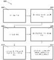
[0092]도 19는 고정-거리 AR/MR 시스템(300)의 사용자에게 신체-중심 방식으로 가상 객체(예컨대, 도 14에서와 같은 사용자 인터페이스(506))를 디스플레이하는 다른 방법(600')을 도시한다. 단계들(602, 604, 606, 608 및 612)은 도 18에 도시된 방법(600)의 대응하는 단계들과 동일하다.[0092]FIG. 19 illustrates another
[0093]도 19에 도시된 방법(600')은, 선택적인 단계(614)에서 이미지가 캡처되기 때문에, 도 18에 도시된 방법(600)과 상이하다. 예컨대, 고정-거리 AR/MR 시스템(300) 내의 이미지 획득 디바이스(308)(도 14 참조)는 사용자의 FOV를 근사화하는 이미지를 캡처할 수 있다.[0093]The method 600' shown in FIG. 19 differs from the
[0094]선택적인 단계(616)에서, 머신 비전 광학 흐름 분석은 캡처된 이미지에 기반하여 수행된다. 광학 흐름 분석은 시스템의 움직임으로부터 발생된 드리프트를 정정한다. 예컨대, 고정-거리 AR/MR 시스템(300)의 제어기(304)는 캡처된 이미지에 기반하여 머신 비전 광학 흐름 분석을 수행할 수 있다.[0094]At
[0095]단계(610)에서, 단일의 미리 결정된 광학 평면의 허용오차 범위 내에서 디스플레이하도록 구성되는 가상 이미지는 머리 포즈, 신체 포즈 및 머신 비전 광학 흐름 분석의 결과에 기반하여 생성된다. 예컨대, 고정-거리 AR/MR 시스템(300) 내의 제어기(304)의 3-D 렌더링 엔진은 머리 포즈, 신체 포즈 및 머신 비전 광학 흐름 분석의 결과에 기반하여 사용자의 FOV에서 디스플레이되도록 구성된 가상 이미지를 렌더링할 수 있다. 3-D 렌더링 엔진은 사용자의 신체 포즈에 대해 사용자의 머리 포즈에 기반하여 생성된 가상 이미지를 변경할 수 있다(도 13 및 14 비교). 가상 이미지를 렌더링할 때 머신 비전 광학 흐름 분석의 결과를 포함하는 것은 시스템 드리프트를 정정하고, 더 정확하게 렌더링된 가상 이미지를 발생시킨다. 가상 이미지는 도 13 및 14에 도시된 사용자 인터페이스(506)의 부분일 수 있다. 가상 이미지는 3-D 이미지의 부분(예컨대, 사용자의 좌측 및 우측 눈들에 동시에 디스플레이될 때 3-D 이미지를 렌더링하도록 구성된 한 쌍의 이미지들 중 좌측 이미지)일 수 있다.[0095]At
[0096]위에 설명된 고정-거리 AR/MR 시스템들은, 감소된 복잡성, 사이즈 및 비용으로부터 이익을 얻을 수 있는 다양한 일반적인 시스템들의 예들로서 제공된다. 따라서, 본원에 설명된 고정-거리 광학 시스템들의 사용은 개시된 고정-거리 AR/MR 시스템들에 제한되지 않으며, 오히려 임의의 광학 시스템에 적용 가능하다.[0096]The fixed-range AR/MR systems described above are provided as examples of various general systems that can benefit from reduced complexity, size, and cost. Thus, the use of the fixed-range optical systems described herein is not limited to the disclosed fixed-range AR/MR systems, but rather is applicable to any optical system.
[0097]본 발명의 다양한 예시적인 실시예들이 본원에서 설명된다. 비-제한적인 의미로 이들 예들에 대한 참조가 행해진다. 그 예들은, 본 발명의 더 넓게 적용가능한 양상들을 예시하기 위해 제공된다. 다양한 변화들이 설명된 발명에 대해 행해질 수 있으며, 등가물들이 본 발명의 실제 사상 및 범위를 벗어나지 않으면서 대체될 수 있다. 부가적으로, 다수의 수정들은, 특정 상황, 재료, 재료의 조성, 프로세스, 프로세스 동작(들) 또는 단계(들)를 본 발명의 목적(들), 사상 또는 범위에 적응시키도록 행해질 수 있다. 추가로, 본원에서 설명되고 예시된 개별 변동들 각각은, 본 발명들의 사상 또는 범위를 벗어나지 않으면서 다른 여러 개의 실시예들 중 임의의 실시예의 특징들로부터 쉽게 분리될 수 있거나 이들과 결합될 수 있는 이산 컴포넌트들 및 특징들을 갖는다는 것이 당업자들에 의해 인지될 것이다. 그러한 모든 수정들은, 본 개시내용과 연관된 청구항들의 범위 내에 있는 것으로 의도된다.[0097]Various exemplary embodiments of the invention are described herein. Reference is made to these examples in a non-limiting sense. The examples are provided to illustrate more broadly applicable aspects of the invention. Various changes may be made to the described invention, and equivalents may be substituted without departing from the true spirit and scope of the invention. Additionally, numerous modifications may be made to adapt a particular situation, material, composition of material, process, process action(s) or step(s) to the object(s), spirit or scope of the invention. Additionally, each of the individual variations described and illustrated herein may be readily separated from or combined with features of any of the other several embodiments without departing from the spirit or scope of the present inventions. It will be recognized by those skilled in the art that it has discrete components and features. All such modifications are intended to be within the scope of the claims associated with this disclosure.
[0098]본 발명은, 본 발명의 디바이스들을 사용하여 수행될 수 있는 방법들을 포함한다. 방법들은, 그러한 적절한 디바이스를 제공하는 동작을 포함할 수 있다. 그러한 제공은 최종 사용자에 의해 수행될 수 있다. 즉, “제공하는” 동작은 단지, 최종 사용자가 본 방법에서 필수적인 디바이스를 제공하도록 획득, 액세스, 접근, 포지셔닝, 셋-업, 활성화, 파워-업 또는 다른 방식으로 동작하는 것을 요구한다. 본원에서 인용된 방법들은, 논리적으로 가능한 인용된 이벤트들의 임의의 순서뿐만 아니라 이벤트들의 인용된 순서로 수행될 수 있다.[0098]The invention includes methods that may be performed using the devices of the invention. Methods may include providing such a suitable device. Such provision may be performed by the end user. That is, the act of “providing” merely requires the end user to obtain, access, access, position, set-up, activate, power-up or otherwise act to provide the device necessary for the present method. The methods recited herein may be performed in the recited order of events, as well as in any order of recited events that is logically possible.
[0099]본 발명의 예시적인 양상들은, 재료 선택 및 제조에 대한 세부사항들과 함께 위에서 기술되었다. 본 발명의 다른 세부사항들에 대해, 이들은, 위에서-참조된 특허들 및 공개공보들과 관련하여 인지될 뿐만 아니라 당업자들에 의해 일반적으로 알려지거나 인지될 수 있다. 이들은 공통적으로 또는 논리적으로 이용되는 바와 같은 부가적인 동작들의 관점들에서 본 발명의 방법-기반 양상들에 관련하여 적용될 수 있다.[0099]Exemplary aspects of the invention have been described above along with details of material selection and manufacture. As for other details of the invention, these are generally known or may be recognized by those skilled in the art as well as being recognized in connection with the above-referenced patents and publications. These may be applied in relation to the method-based aspects of the present invention in terms of additional operations as commonly or logically employed.
[00100]부가적으로, 본 발명이 다양한 피처들을 선택적으로 포함하는 몇몇의 예들을 참조하여 설명되었지만, 본 발명은, 본 발명의 각각의 변동에 대해 고려된 바와 같이 설명되거나 표시된 것으로 제한되지 않을 것이다. 다양한 변화들이 설명된 발명에 대해 행해질 수 있으며, (본원에서 인용되었는지 또는 일부 간략화를 위해 포함되지 않았는지 여부에 관계없이) 등가물들이 본 발명의 실제 사상 및 범위를 벗어나지 않으면서 대체될 수 있다. 부가적으로, 다양한 값들이 제공되는 경우, 그 범위의 상한과 하한 사이의 모든 각각의 개재 값 및 그 언급된 범위 내의 임의의 다른 언급된 또는 개재 값이 본 발명 내에 포함되는 것으로 해석된다.[00100]Additionally, while the invention has been described with reference to several examples that optionally include various features, the invention is not to be limited to what has been described or indicated as contemplated for each variation of the invention. Various changes may be made to the described invention, and equivalents may be substituted without departing from the true spirit and scope of the invention (whether not cited herein or included for some brevity). Additionally, where multiple values are provided, every intervening value between the upper and lower limits of that range and any other stated or intervening value within that stated range is intended to be encompassed within the invention.
[00101]또한, 설명된 본 발명의 변동들의 임의의 선택적인 피처가 본원에 설명된 피처들 중 임의의 하나 이상과 결합하여 또는 독립적으로 기술되고 청구될 수 있다는 것이 고려된다. 단수 아이템에 대한 참조는, 복수의 동일한 아이템들이 존재하는 가능성을 포함한다. 보다 구체적으로, 본원 및 본원에 연관된 청구항들에서 사용된 바와 같이, 단수 형태들은, 명확하게 달리 언급되지 않으면 복수의 지시 대상들을 포함한다. 즉, 단수들의 사용은 본 개시내용과 연관된 청구항들뿐 아니라 위의 설명의 청구대상 아이템 중 "적어도 하나"를 허용한다. 이 청구항들이 임의의 선택적인 엘리먼트를 배제하도록 작성될 수 있다는 것에 추가로 주의한다. 따라서, 이런 서술은 청구항 엘리먼트들의 나열과 관련하여 "오로지", "오직" 등 같은 그런 배타적인 용어의 사용, 또는 "부정적" 제한의 사용을 위한 선행 기초로서 역할을 하도록 의도된다.[00101]It is also contemplated that any optional feature of the described inventive variations may be described and claimed independently or in combination with any one or more of the features described herein. A reference to a singular item includes the possibility that there are multiple identical items. More specifically, as used in this application and in the claims associated therewith, the singular forms “a,” “an” and “an” include plural referents unless the context clearly dictates otherwise. That is, the use of the singular permits “at least one” of the claimed item of the above description as well as claims related to this disclosure. It is further noted that these claims may be written to exclude any optional element. Accordingly, this statement is intended to serve as antecedent basis for use of such exclusive terms as "only", "only", etc., in connection with the recitation of claim elements, or use of a "negative" limitation.
[00102]그런 배타적 용어의 사용 없이, 본 개시내용과 연관된 청구항들에서 "포함하는"이라는 용어는, 주어진 수의 엘리먼트들이 그런 청구항들에 열거되는지 여부에 무관하게 임의의 부가적인 엘리먼트의 포함을 허용할 수 있거나, 또는 특징의 부가는 그 청구항들에 기술된 엘리먼트의 성질을 변환하는 것으로 간주될 수 있다. 본원에 구체적으로 정의된 바를 제외하고, 본원에 사용된 모든 기술적 및 과학적 용어들은 청구항 유효성을 유지하면서 가능한 한 일반적으로 이해되는 의미로 넓게 제공되어야 한다.[00102]Without the use of such exclusive terms, the term "comprising" in the claims associated with this disclosure may permit the inclusion of any additional element regardless of whether a given number of elements are recited in such claims, or , or the addition of a feature may be regarded as modifying the property of an element recited in the claims. Except as specifically defined herein, all technical and scientific terms used herein are to be given as broadly as possible a commonly understood meaning while maintaining claim validity.
[00103]본 발명의 범위는 제공된 예들 및/또는 본원 명세서로 제한되는 것이 아니라, 오히려 본 개시내용과 연관된 청구항 문언의 범위에 의해서만 제한된다.[00103]The scope of the present invention is not limited to the examples provided and/or this specification, but rather only by the scope of the claim language associated with this disclosure.
[00104]위의 명세서에서, 본 발명은 본 발명의 특정 실시예들을 참조하여 설명되었다. 그러나, 본 발명의 더 넓은 사상 및 범위를 벗어나지 않으면서 다양한 수정들 및 변경들이 본 발명에 행해질 수 있다는 것은 명백할 것이다. 예컨대, 위에서-설명된 프로세스 흐름들은, 프로세스 동작들의 특정한 순서를 참조하여 설명된다. 그러나, 설명된 프로세스 동작들 대부분의 순서는 본 발명의 범위 또는 동작에 영향을 주지 않으면서 변경될 수 있다. 따라서, 명세서 및 도면들은 제한적인 의미보다는 예시적인 의미로 간주될 것이다.[00104]In the above specification, the invention has been described with reference to specific embodiments of the invention. However, it will be apparent that various modifications and changes may be made to the present invention without departing from the broader spirit and scope of the invention. For example, the above-described process flows are described with reference to a specific order of process actions. However, the order of many of the described process actions may be changed without affecting the scope or operation of the invention. Accordingly, the specification and drawings are to be regarded in an illustrative rather than restrictive sense.
Claims (10)
Translated fromKorean광 빔을 생성하도록 구성된 광 소스;
내부 전반사(total internal reflection)에 의해 상기 광 빔 중 적어도 일부를 전파하도록 구성된 광 안내 광학 엘리먼트(light guiding optical element);
사용자의 머리에 인접하게 배치되고 상기 사용자의 머리 포즈를 계산하기 위한 제1 값을 측정하도록 구성된 제1 관성 측정 유닛;
사용자의 신체(body) 포즈를 계산하기 위한 제3 값을 측정하도록 구성된 제3 관성 측정 유닛 ― 상기 제3 관성 측정 유닛은 상기 사용자의 신체 상의 미리 결정된 위치에 고정될 때에만 활성화됨 ―; 및
머신 비전 광학 흐름 분석(machine vision optical flow analysis)을 위해 이미지를 캡처하도록 구성된 카메라
를 포함하고,
상기 고정-거리 디스플레이 시스템은, 상기 사용자의 신체 포즈에 대한 상기 사용자의 머리 포즈에 기초하여, 상기 사용자의 시야에 신체 중심(body-centric) 가상 사용자 인터페이스를 디스플레이하도록 구성되고,
상기 신체 중심 가상 사용자 인터페이스는 상기 사용자의 신체에 대한 고정된 위치 및 고정된 거리에 디스플레이되고,
상기 신체 중심 가상 사용자 인터페이스는, 상기 사용자의 머리의 움직임에 따라 변화하는, 상기 사용자의 머리에 상대적인 위치 및 거리에 디스플레이되어서, 상기 사용자의 머리가 상기 사용자의 신체에 대해 상대적으로 움직이면, 상기 신체 중심 가상 사용자 인터페이스는 상기 사용자의 시야에서 움직이는,
고정-거리 디스플레이 시스템.As a fixed-distance display system,
a light source configured to generate a light beam;
a light guiding optical element configured to propagate at least a portion of the light beam by total internal reflection;
a first inertial measurement unit disposed adjacent to the user's head and configured to measure a first value for calculating the user's head pose;
a third inertial measurement unit configured to measure a third value for calculating a body pose of a user, the third inertial measurement unit being activated only when fixed to a predetermined position on the body of the user; and
A camera configured to capture images for machine vision optical flow analysis.
including,
wherein the fixed-distance display system is configured to display a body-centric virtual user interface in the user's field of view based on the user's head pose relative to the user's body pose;
the body-centric virtual user interface is displayed at a fixed location and at a fixed distance from the user's body;
The body-centered virtual user interface is displayed at a position and distance relative to the user's head that changes according to the movement of the user's head, so that when the user's head moves relative to the user's body, the body-centered virtual user interface is displayed. a virtual user interface moving in the user's field of view;
Fixed-distance display system.
상기 고정-거리 디스플레이 시스템은, 0.2 디옵터 내지 0.6 디옵터를 벗어나지 않는 치수(dimension)들을 갖는 3차원 가상 이미지들을 디스플레이하도록 구성되는,
고정-거리 디스플레이 시스템.According to claim 1,
wherein the fixed-distance display system is configured to display three-dimensional virtual images having dimensions that do not deviate from 0.2 diopters to 0.6 diopters.
Fixed-distance display system.
상기 사용자의 머리 포즈를 계산하기 위한 제2 값을 측정하도록 구성된 제2 관성 측정 유닛을 더 포함하는,
고정-거리 디스플레이 시스템.According to claim 1,
Further comprising a second inertial measurement unit configured to measure a second value for calculating the head pose of the user.
Fixed-distance display system.
상기 제2 관성 측정 유닛은 상기 사용자의 머리에 인접하게 배치되는,
고정-거리 디스플레이 시스템.According to claim 3,
wherein the second inertial measurement unit is disposed adjacent to the user's head;
Fixed-distance display system.
상기 제3 관성 측정 유닛은 상기 사용자의 허리에 인접하게 배치되는,
고정-거리 디스플레이 시스템.According to claim 1,
The third inertial measurement unit is disposed adjacent to the user's waist,
Fixed-distance display system.
상기 제1 관성 측정 유닛, 상기 제2 관성 측정 유닛, 상기 제3 관성 측정 유닛 및 상기 카메라는 상기 사용자의 시야를 상기 사용자의 신체 위치에 매칭시키도록 구성되는,
고정-거리 디스플레이 시스템.According to claim 3,
The first inertial measurement unit, the second inertial measurement unit, the third inertial measurement unit and the camera are configured to match the user's field of view to the user's body position.
Fixed-distance display system.
상기 신체 중심 가상 사용자 인터페이스는, 상기 고정된 거리에서 상기 사용자의 신체 주위에 아크(arc) 형태로 디스플레이되는 복수의 사용자 인터페이스 객체들을 포함하는,
고정-거리 디스플레이 시스템.According to claim 1,
The body-centered virtual user interface includes a plurality of user interface objects displayed in an arc shape around the user's body at the fixed distance.
Fixed-distance display system.
상기 명령들의 시퀀스는, 프로세서에 의해 실행될 때, 상기 프로세서로 하여금 디스플레이하기 위한 방법을 실행하게 하고,
상기 방법은:
광 빔을 생성하는 단계;
내부 전반사에 의해 상기 광 빔 중 적어도 일부를 전파하는 단계;
사용자의 머리에 인접하게 배치된 제1 관성 측정 유닛을 이용하여 머리 포즈에 관련된 제1 값을 측정하는 단계;
상기 제1 값에 기반하여 사용자의 상기 머리 포즈를 계산하는 단계;
제3 관성 측정 유닛을 이용하여 신체 포즈에 관련된 제3 값을 측정하는 단계 ― 상기 제3 관성 측정 유닛은 상기 사용자의 신체 상의 미리 결정된 위치에 고정될 때에만 활성화됨 ―;
상기 제3 값에 기반하여 상기 사용자의 상기 신체 포즈를 계산하는 단계;
이미지를 캡처하는 단계;
상기 이미지에 기반하여 머신 비전 광학 흐름 분석을 수행하는 단계; 및
상기 사용자의 신체에 대한 고정된 위치 및 고정된 거리에, 상기 사용자의 신체 포즈에 대한 상기 사용자의 머리 포즈에 기초하여, 상기 사용자의 시야에 신체 중심 가상 사용자 인터페이스를 디스플레이하는 단계
를 포함하고,
상기 신체 중심 가상 사용자 인터페이스는, 상기 사용자의 머리의 움직임에 따라 변화하는, 상기 사용자의 머리에 상대적인 위치 및 거리에 디스플레이되어서, 상기 사용자의 머리가 상기 사용자의 신체에 대해 상대적으로 움직이면, 상기 신체 중심 가상 사용자 인터페이스는 상기 사용자의 시야에서 움직이는,
비-일시적인 컴퓨터 판독 가능 매체.A non-transitory computer readable medium having a sequence of instructions stored thereon, comprising:
the sequence of instructions, when executed by a processor, causes the processor to execute a method for display;
The method is:
generating a light beam;
propagating at least a portion of the light beam by total internal reflection;
measuring a first value related to the head pose using a first inertial measurement unit disposed adjacent to the user's head;
calculating the head pose of the user based on the first value;
measuring a third value related to a body pose using a third inertial measurement unit, the third inertial measurement unit being activated only when fixed at a predetermined position on the user's body;
calculating the body pose of the user based on the third value;
capturing an image;
performing machine vision optical flow analysis based on the image; and
displaying a body-centric virtual user interface in the field of view of the user, based on a pose of the user's head relative to a pose of the body of the user, at a fixed position and a fixed distance relative to the body of the user;
including,
The body-centered virtual user interface is displayed at a position and distance relative to the user's head that changes according to the movement of the user's head, so that when the user's head moves relative to the user's body, the body-centered virtual user interface is displayed. a virtual user interface moving in the user's field of view;
A non-transitory computer readable medium.
상기 신체 중심 가상 사용자 인터페이스는, 상기 고정된 거리에서 상기 사용자의 신체 주위에 아크 형태로 디스플레이되는 복수의 사용자 인터페이스 객체들을 포함하는,
비-일시적인 컴퓨터 판독 가능 매체.According to claim 8,
The body-centered virtual user interface includes a plurality of user interface objects displayed in an arc shape around the user's body at the fixed distance.
A non-transitory computer readable medium.
상기 프로세서에 의해 실행될 때, 상기 프로세서로 하여금, 0.2 디옵터 내지 0.6 디옵터를 벗어나지 않는 치수들을 갖는 3차원 가상 이미지들을 디스플레이하게 하는 명령들을 더 포함하는,
비-일시적인 컴퓨터 판독 가능 매체.According to claim 8,
further comprising instructions that, when executed by the processor, cause the processor to display three-dimensional virtual images having dimensions that do not deviate from 0.2 diopters to 0.6 diopters;
A non-transitory computer readable medium.
Priority Applications (1)
| Application Number | Priority Date | Filing Date | Title |
|---|---|---|---|
| KR1020247001408AKR102762435B1 (en) | 2016-08-02 | 2017-07-31 | Fixed-distance virtual and augmented reality systems and methods |
Applications Claiming Priority (4)
| Application Number | Priority Date | Filing Date | Title |
|---|---|---|---|
| US201662370117P | 2016-08-02 | 2016-08-02 | |
| US62/370,117 | 2016-08-02 | ||
| PCT/US2017/044762WO2018026737A1 (en) | 2016-08-02 | 2017-07-31 | Fixed-distance virtual and augmented reality systems and methods |
| KR1020217006131AKR20210025721A (en) | 2016-08-02 | 2017-07-31 | Fixed-distance virtual and augmented reality systems and methods |
Related Parent Applications (1)
| Application Number | Title | Priority Date | Filing Date |
|---|---|---|---|
| KR1020217006131ADivisionKR20210025721A (en) | 2016-08-02 | 2017-07-31 | Fixed-distance virtual and augmented reality systems and methods |
Related Child Applications (1)
| Application Number | Title | Priority Date | Filing Date |
|---|---|---|---|
| KR1020247001408ADivisionKR102762435B1 (en) | 2016-08-02 | 2017-07-31 | Fixed-distance virtual and augmented reality systems and methods |
Publications (2)
| Publication Number | Publication Date |
|---|---|
| KR20220164084Atrue KR20220164084A (en) | 2022-12-12 |
| KR102626821B1 KR102626821B1 (en) | 2024-01-18 |
Family
ID=61071680
Family Applications (4)
| Application Number | Title | Priority Date | Filing Date |
|---|---|---|---|
| KR1020227041575AActiveKR102626821B1 (en) | 2016-08-02 | 2017-07-31 | Fixed-distance virtual and augmented reality systems and methods |
| KR1020197006281ACeasedKR20190034321A (en) | 2016-08-02 | 2017-07-31 | Fixed-distance virtual and augmented reality systems and methods |
| KR1020247001408AActiveKR102762435B1 (en) | 2016-08-02 | 2017-07-31 | Fixed-distance virtual and augmented reality systems and methods |
| KR1020217006131ACeasedKR20210025721A (en) | 2016-08-02 | 2017-07-31 | Fixed-distance virtual and augmented reality systems and methods |
Family Applications After (3)
| Application Number | Title | Priority Date | Filing Date |
|---|---|---|---|
| KR1020197006281ACeasedKR20190034321A (en) | 2016-08-02 | 2017-07-31 | Fixed-distance virtual and augmented reality systems and methods |
| KR1020247001408AActiveKR102762435B1 (en) | 2016-08-02 | 2017-07-31 | Fixed-distance virtual and augmented reality systems and methods |
| KR1020217006131ACeasedKR20210025721A (en) | 2016-08-02 | 2017-07-31 | Fixed-distance virtual and augmented reality systems and methods |
Country Status (9)
| Country | Link |
|---|---|
| US (5) | US10649211B2 (en) |
| EP (1) | EP3494549A4 (en) |
| JP (1) | JP6972105B2 (en) |
| KR (4) | KR102626821B1 (en) |
| CN (2) | CN109661687B (en) |
| AU (2) | AU2017305227B2 (en) |
| CA (1) | CA3032567A1 (en) |
| IL (3) | IL264489B (en) |
| WO (1) | WO2018026737A1 (en) |
Families Citing this family (26)
| Publication number | Priority date | Publication date | Assignee | Title |
|---|---|---|---|---|
| US11138793B2 (en) | 2014-03-14 | 2021-10-05 | Magic Leap, Inc. | Multi-depth plane display system with reduced switching between depth planes |
| CN112764536B (en) | 2015-03-05 | 2025-04-01 | 奇跃公司 | Systems and methods for augmented reality |
| US10180734B2 (en) | 2015-03-05 | 2019-01-15 | Magic Leap, Inc. | Systems and methods for augmented reality |
| US10838207B2 (en) | 2015-03-05 | 2020-11-17 | Magic Leap, Inc. | Systems and methods for augmented reality |
| US10962780B2 (en)* | 2015-10-26 | 2021-03-30 | Microsoft Technology Licensing, Llc | Remote rendering for virtual images |
| KR20180090355A (en) | 2015-12-04 | 2018-08-10 | 매직 립, 인코포레이티드 | Recirculation systems and methods |
| KR102726904B1 (en) | 2016-02-11 | 2024-11-05 | 매직 립, 인코포레이티드 | Multi-depth plane display system with reduced switching between depth planes |
| AU2017225977C1 (en) | 2016-03-04 | 2023-08-03 | Magic Leap, Inc. | Current drain reduction in AR/VR display systems |
| US10698215B2 (en) | 2016-03-25 | 2020-06-30 | Magic Leap, Inc. | Virtual and augmented reality systems and methods |
| KR102626821B1 (en) | 2016-08-02 | 2024-01-18 | 매직 립, 인코포레이티드 | Fixed-distance virtual and augmented reality systems and methods |
| US10812936B2 (en) | 2017-01-23 | 2020-10-20 | Magic Leap, Inc. | Localization determination for mixed reality systems |
| AU2018234921B2 (en) | 2017-03-17 | 2021-10-07 | Magic Leap, Inc. | Mixed reality system with color virtual content warping and method of generating virtual content using same |
| CA3054617A1 (en) | 2017-03-17 | 2018-09-20 | Magic Leap, Inc. | Mixed reality system with multi-source virtual content compositing and method of generating virtual content using same |
| WO2018170470A1 (en) | 2017-03-17 | 2018-09-20 | Magic Leap, Inc. | Mixed reality system with virtual content warping and method of generating virtual content using same |
| US10338400B2 (en) | 2017-07-03 | 2019-07-02 | Holovisions LLC | Augmented reality eyewear with VAPE or wear technology |
| US10859834B2 (en) | 2017-07-03 | 2020-12-08 | Holovisions | Space-efficient optical structures for wide field-of-view augmented reality (AR) eyewear |
| EP4510558A3 (en) | 2018-03-14 | 2025-05-07 | Magic Leap, Inc. | Display systems and methods for clipping content to increase viewing comfort |
| US11966055B2 (en) | 2018-07-19 | 2024-04-23 | Magic Leap, Inc. | Content interaction driven by eye metrics |
| CN109948410B (en)* | 2018-07-20 | 2020-09-11 | 华为技术有限公司 | Electronic equipment with texture detection function |
| CN112513712B (en) | 2018-07-23 | 2023-05-09 | 奇跃公司 | Mixed reality system with virtual content warping and method of generating virtual content using the system |
| JP7413345B2 (en) | 2018-07-23 | 2024-01-15 | マジック リープ, インコーポレイテッド | Intra-field subcode timing in field-sequential displays |
| US11233954B1 (en)* | 2019-01-24 | 2022-01-25 | Rockwell Collins, Inc. | Stereo infrared imaging for head mounted devices |
| KR102743763B1 (en)* | 2019-02-11 | 2024-12-17 | 삼성전자주식회사 | Electronic device for providing augmented reality user interface and operating method thereof |
| US11265487B2 (en)* | 2019-06-05 | 2022-03-01 | Mediatek Inc. | Camera view synthesis on head-mounted display for virtual reality and augmented reality |
| JP7582675B2 (en) | 2019-11-06 | 2024-11-13 | ヒーズ アイピー ホールディングス エルエルシー | System and method for displaying objects with depth |
| US12326971B1 (en) | 2024-10-03 | 2025-06-10 | Bansen Labs, Llc | System and method for facilitating adaptive recentering in virtual reality environments |
Citations (3)
| Publication number | Priority date | Publication date | Assignee | Title |
|---|---|---|---|---|
| KR20140034252A (en)* | 2011-06-23 | 2014-03-19 | 마이크로소프트 코포레이션 | Total field of view classification for head-mounted display |
| KR20160013939A (en)* | 2013-05-22 | 2016-02-05 | 마이크로소프트 테크놀로지 라이센싱, 엘엘씨 | Body-locked placement of augmented reality objects |
| KR20160023888A (en)* | 2013-06-25 | 2016-03-03 | 마이크로소프트 테크놀로지 라이센싱, 엘엘씨 | Indicating out-of-view augmented reality images |
Family Cites Families (257)
| Publication number | Priority date | Publication date | Assignee | Title |
|---|---|---|---|---|
| US4462165A (en) | 1983-01-31 | 1984-07-31 | The Boeing Company | Three axis orientation sensor for an aircraft or the like |
| US6701296B1 (en) | 1988-10-14 | 2004-03-02 | James F. Kramer | Strain-sensing goniometers, systems, and recognition algorithms |
| US5047952A (en) | 1988-10-14 | 1991-09-10 | The Board Of Trustee Of The Leland Stanford Junior University | Communication system for deaf, deaf-blind, or non-vocal individuals using instrumented glove |
| AU675077B2 (en) | 1992-08-14 | 1997-01-23 | British Telecommunications Public Limited Company | Position location system |
| CA2358682A1 (en) | 1992-08-14 | 1994-03-03 | British Telecommunications Public Limited Company | Position location system |
| US5583974A (en) | 1993-05-10 | 1996-12-10 | Apple Computer, Inc. | Computer graphics system having high performance multiple layer Z-buffer |
| TW275590B (en) | 1994-12-09 | 1996-05-11 | Sega Enterprises Kk | Head mounted display and system for use therefor |
| US5592401A (en) | 1995-02-28 | 1997-01-07 | Virtual Technologies, Inc. | Accurate, rapid, reliable position sensing using multiple sensing technologies |
| US5930741A (en) | 1995-02-28 | 1999-07-27 | Virtual Technologies, Inc. | Accurate, rapid, reliable position sensing using multiple sensing technologies |
| US5684498A (en) | 1995-06-26 | 1997-11-04 | Cae Electronics Ltd. | Field sequential color head mounted display with suppressed color break-up |
| WO1997020244A1 (en) | 1995-11-27 | 1997-06-05 | Cae Electronics Ltd. | Method and apparatus for displaying a virtual environment on a video display |
| US5784115A (en) | 1996-12-31 | 1998-07-21 | Xerox Corporation | System and method for motion compensated de-interlacing of video frames |
| US6163155A (en) | 1999-01-28 | 2000-12-19 | Dresser Industries, Inc. | Electromagnetic wave resistivity tool having a tilted antenna for determining the horizontal and vertical resistivities and relative dip angle in anisotropic earth formations |
| US6407736B1 (en) | 1999-06-18 | 2002-06-18 | Interval Research Corporation | Deferred scanline conversion architecture |
| GB9917591D0 (en) | 1999-07-28 | 1999-09-29 | Marconi Electronic Syst Ltd | Head tracker system |
| JP2001208529A (en) | 2000-01-26 | 2001-08-03 | Mixed Reality Systems Laboratory Inc | Measuring apparatus, control method thereof and memory medium |
| AU2001233019A1 (en) | 2000-01-28 | 2001-08-07 | Intersense, Inc. | Self-referenced tracking |
| US7878905B2 (en) | 2000-02-22 | 2011-02-01 | Creative Kingdoms, Llc | Multi-layered interactive play experience |
| US7445550B2 (en) | 2000-02-22 | 2008-11-04 | Creative Kingdoms, Llc | Magical wand and interactive play experience |
| US6985620B2 (en) | 2000-03-07 | 2006-01-10 | Sarnoff Corporation | Method of pose estimation and model refinement for video representation of a three dimensional scene |
| US6891533B1 (en) | 2000-04-11 | 2005-05-10 | Hewlett-Packard Development Company, L.P. | Compositing separately-generated three-dimensional images |
| US6738044B2 (en) | 2000-08-07 | 2004-05-18 | The Regents Of The University Of California | Wireless, relative-motion computer input device |
| US20020180727A1 (en) | 2000-11-22 | 2002-12-05 | Guckenberger Ronald James | Shadow buffer control module method and software construct for adjusting per pixel raster images attributes to screen space and projector features for digital warp, intensity transforms, color matching, soft-edge blending, and filtering for multiple projectors and laser projectors |
| US6691074B1 (en) | 2001-02-08 | 2004-02-10 | Netmore Ltd. | System for three dimensional positioning and tracking |
| US7620592B2 (en) | 2001-02-26 | 2009-11-17 | First Data Corporation | Tiered processing method and system for identifying and mitigating merchant risk |
| US6861982B2 (en) | 2001-08-16 | 2005-03-01 | Itt Manufacturing Enterprises, Inc. | System for determining position of an emitter |
| US7113618B2 (en) | 2001-09-18 | 2006-09-26 | Intel Corporation | Portable virtual reality |
| US7487127B2 (en) | 2002-03-27 | 2009-02-03 | First Data Corporation | Merchant cash payment systems and methods |
| JP2003337963A (en) | 2002-05-17 | 2003-11-28 | Seiko Epson Corp | Image processing apparatus, image processing method, image processing program, and recording medium therefor |
| CA2488730A1 (en)* | 2002-06-11 | 2003-12-18 | First Data Corporation | Value processing network and methods |
| US20040078105A1 (en) | 2002-09-03 | 2004-04-22 | Charles Moon | System and method for workflow process management |
| US9153074B2 (en) | 2011-07-18 | 2015-10-06 | Dylan T X Zhou | Wearable augmented reality eyeglass communication device including mobile phone and mobile computing via virtual touch screen gesture control and neuron command |
| JP3984907B2 (en)* | 2002-11-29 | 2007-10-03 | キヤノン株式会社 | Image observation system |
| US20070155589A1 (en) | 2002-12-04 | 2007-07-05 | Philip Feldman | Method and Apparatus for Operatively Controlling a Virtual Reality Scenario with an Isometric Exercise System |
| JP2004213350A (en) | 2002-12-27 | 2004-07-29 | Seiko Epson Corp | Force sense presentation device and image correction method |
| US20050107870A1 (en) | 2003-04-08 | 2005-05-19 | Xingwu Wang | Medical device with multiple coating layers |
| US7643025B2 (en) | 2003-09-30 | 2010-01-05 | Eric Belk Lange | Method and apparatus for applying stereoscopic imagery to three-dimensionally defined substrates |
| US7443154B1 (en) | 2003-10-04 | 2008-10-28 | Seektech, Inc. | Multi-sensor mapping omnidirectional sonde and line locator |
| CA2450837A1 (en) | 2003-11-25 | 2005-05-25 | University Of New Brunswick | Induction magnetometer |
| US9229540B2 (en) | 2004-01-30 | 2016-01-05 | Electronic Scripting Products, Inc. | Deriving input from six degrees of freedom interfaces |
| US20160098095A1 (en) | 2004-01-30 | 2016-04-07 | Electronic Scripting Products, Inc. | Deriving Input from Six Degrees of Freedom Interfaces |
| US7653883B2 (en) | 2004-07-30 | 2010-01-26 | Apple Inc. | Proximity detector in handheld device |
| JP4508820B2 (en) | 2004-10-19 | 2010-07-21 | 株式会社ワコム | 3D information detection system and 3D information input device |
| CN101080762A (en) | 2004-11-19 | 2007-11-28 | Daem交互有限公司 | Personal device and method with image-acquisition functions for the application of augmented reality resources |
| JP5631535B2 (en) | 2005-02-08 | 2014-11-26 | オブロング・インダストリーズ・インコーポレーテッド | System and method for a gesture-based control system |
| CA2605670C (en) | 2005-04-26 | 2014-08-05 | Imax Corporation | Electronic projection systems and methods |
| US8308563B2 (en) | 2005-08-30 | 2012-11-13 | Nintendo Co., Ltd. | Game system and storage medium having game program stored thereon |
| US8157651B2 (en) | 2005-09-12 | 2012-04-17 | Nintendo Co., Ltd. | Information processing program |
| JP4437228B2 (en) | 2005-11-07 | 2010-03-24 | 大学共同利用機関法人情報・システム研究機構 | Imaging apparatus and imaging method using defocus structure |
| KR100722229B1 (en)* | 2005-12-02 | 2007-05-29 | 한국전자통신연구원 | Apparatus and Method for Instant Generation / Control of Virtual Reality Interactive Human Body Model for User-Centered Interface |
| US9910497B2 (en) | 2006-02-08 | 2018-03-06 | Oblong Industries, Inc. | Gestural control of autonomous and semi-autonomous systems |
| US8370383B2 (en) | 2006-02-08 | 2013-02-05 | Oblong Industries, Inc. | Multi-process interactive systems and methods |
| US9823747B2 (en) | 2006-02-08 | 2017-11-21 | Oblong Industries, Inc. | Spatial, multi-modal control device for use with spatial operating system |
| US8531396B2 (en) | 2006-02-08 | 2013-09-10 | Oblong Industries, Inc. | Control system for navigating a principal dimension of a data space |
| US8537111B2 (en) | 2006-02-08 | 2013-09-17 | Oblong Industries, Inc. | Control system for navigating a principal dimension of a data space |
| JP4151982B2 (en) | 2006-03-10 | 2008-09-17 | 任天堂株式会社 | Motion discrimination device and motion discrimination program |
| JP4684147B2 (en) | 2006-03-28 | 2011-05-18 | 任天堂株式会社 | Inclination calculation device, inclination calculation program, game device, and game program |
| JP4196302B2 (en) | 2006-06-19 | 2008-12-17 | ソニー株式会社 | Information processing apparatus and method, and program |
| JP4804256B2 (en) | 2006-07-27 | 2011-11-02 | キヤノン株式会社 | Information processing method |
| US8194088B1 (en) | 2006-08-03 | 2012-06-05 | Apple Inc. | Selective composite rendering |
| US7921120B2 (en) | 2006-11-30 | 2011-04-05 | D&S Consultants | Method and system for image recognition using a similarity inverse matrix |
| CN101093586A (en) | 2007-07-12 | 2007-12-26 | 上海交通大学 | Parallel collision detection method of real time interactive operation oriented to complex scene |
| US8165352B1 (en) | 2007-08-06 | 2012-04-24 | University Of South Florida | Reconstruction of biometric image templates using match scores |
| IL195389A (en) | 2008-11-19 | 2013-12-31 | Elbit Systems Ltd | System and method for mapping a magnetic field |
| US10095815B2 (en) | 2008-11-19 | 2018-10-09 | Elbit Systems Ltd. | System and a method for mapping a magnetic field |
| US20090115406A1 (en) | 2007-11-01 | 2009-05-07 | General Electric Company | System and method for minimizing mutual inductance coupling between coils in an electromagnetic tracking system |
| US9013505B1 (en) | 2007-11-27 | 2015-04-21 | Sprint Communications Company L.P. | Mobile system representing virtual objects on live camera image |
| KR20090055803A (en) | 2007-11-29 | 2009-06-03 | 광주과학기술원 | Method and apparatus for generating multiview depth map and method for generating variance in multiview image |
| US7795596B2 (en) | 2008-01-03 | 2010-09-14 | Alcatel-Lucent Usa Inc. | Cloaking device detection system |
| WO2009091563A1 (en) | 2008-01-18 | 2009-07-23 | Thomson Licensing | Depth-image-based rendering |
| DE112009000180T5 (en) | 2008-01-23 | 2011-03-31 | Swift-Foot Graphics Ab | Method, apparatus and computer program product for improved graphics performance |
| US20090184825A1 (en) | 2008-01-23 | 2009-07-23 | General Electric Company | RFID Transponder Used for Instrument Identification in an Electromagnetic Tracking System |
| US8926511B2 (en) | 2008-02-29 | 2015-01-06 | Biosense Webster, Inc. | Location system with virtual touch screen |
| US9740293B2 (en) | 2009-04-02 | 2017-08-22 | Oblong Industries, Inc. | Operating environment with gestural control and multiple client devices, displays, and users |
| US9740922B2 (en) | 2008-04-24 | 2017-08-22 | Oblong Industries, Inc. | Adaptive tracking system for spatial input devices |
| US9684380B2 (en) | 2009-04-02 | 2017-06-20 | Oblong Industries, Inc. | Operating environment with gestural control and multiple client devices, displays, and users |
| US8723795B2 (en) | 2008-04-24 | 2014-05-13 | Oblong Industries, Inc. | Detecting, representing, and interpreting three-space input: gestural continuum subsuming freespace, proximal, and surface-contact modes |
| US9495013B2 (en) | 2008-04-24 | 2016-11-15 | Oblong Industries, Inc. | Multi-modal gestural interface |
| US9952673B2 (en) | 2009-04-02 | 2018-04-24 | Oblong Industries, Inc. | Operating environment comprising multiple client devices, multiple displays, multiple users, and gestural control |
| US8446426B2 (en) | 2008-04-28 | 2013-05-21 | Apple Inc. | Technique for visually compositing a group of graphical objects |
| KR20090120159A (en) | 2008-05-19 | 2009-11-24 | 삼성전자주식회사 | Image Synthesis Device and Image Synthesis Method |
| US8929877B2 (en) | 2008-09-12 | 2015-01-06 | Digimarc Corporation | Methods and systems for content processing |
| JP5415054B2 (en) | 2008-10-28 | 2014-02-12 | セイコーエプソン株式会社 | Driving method and electro-optical device |
| WO2010055737A1 (en) | 2008-11-14 | 2010-05-20 | 株式会社ソニー・コンピュータエンタテインメント | Operating device |
| US8188745B2 (en) | 2008-12-05 | 2012-05-29 | Metrotech Corporation Inc. | Precise location and orientation of a concealed dipole transmitter |
| US9465129B1 (en) | 2009-03-06 | 2016-10-11 | See Scan, Inc. | Image-based mapping locating system |
| US8860723B2 (en) | 2009-03-09 | 2014-10-14 | Donya Labs Ab | Bounded simplification of geometrical computer data |
| US8027912B1 (en)* | 2009-04-30 | 2011-09-27 | Intuit Inc. | System and method for merchant risk management |
| JP5177078B2 (en) | 2009-05-26 | 2013-04-03 | 富士通モバイルコミュニケーションズ株式会社 | Information processing device |
| US9933852B2 (en) | 2009-10-14 | 2018-04-03 | Oblong Industries, Inc. | Multi-process interactive systems and methods |
| US8775424B2 (en) | 2010-01-26 | 2014-07-08 | Xerox Corporation | System for creative image navigation and exploration |
| US9134534B2 (en) | 2010-02-28 | 2015-09-15 | Microsoft Technology Licensing, Llc | See-through near-eye display glasses including a modular image source |
| US8581905B2 (en) | 2010-04-08 | 2013-11-12 | Disney Enterprises, Inc. | Interactive three dimensional displays on handheld devices |
| TWI399688B (en) | 2010-06-08 | 2013-06-21 | Waltop Int Corp | Integrated electromagnetic type and capacitive type input apparatus |
| JP2012043308A (en) | 2010-08-20 | 2012-03-01 | Canon Inc | Position and attitude determination method, position and attitude determination device, object model generation method, object model generation device and program |
| US9355305B2 (en) | 2010-10-08 | 2016-05-31 | Panasonic Corporation | Posture estimation device and posture estimation method |
| US20120086630A1 (en)* | 2010-10-12 | 2012-04-12 | Sony Computer Entertainment Inc. | Using a portable gaming device to record or modify a game or application in real-time running on a home gaming system |
| US9122053B2 (en) | 2010-10-15 | 2015-09-01 | Microsoft Technology Licensing, Llc | Realistic occlusion for a head mounted augmented reality display |
| FR2966251B1 (en) | 2010-10-19 | 2014-04-25 | Astrium Sas | SYSTEM FOR ORIENTATION AND POSITIONING OF AN ELECTROMAGNETIC RECEIVER |
| US8660369B2 (en) | 2010-10-25 | 2014-02-25 | Disney Enterprises, Inc. | Systems and methods using mobile devices for augmented reality |
| US8745061B2 (en) | 2010-11-09 | 2014-06-03 | Tibco Software Inc. | Suffix array candidate selection and index data structure |
| GB201020973D0 (en) | 2010-12-10 | 2011-01-26 | Panaplay Ltd | Risk management system and method |
| CN103261944A (en)* | 2010-12-28 | 2013-08-21 | 洛克希德马丁公司 | Head-mounted display devices employing one or more light-reflecting surfaces |
| WO2012100829A1 (en) | 2011-01-27 | 2012-08-02 | Metaio Gmbh | Method for determining correspondences between a first and a second image, and method for determining the pose of a camera |
| US8587583B2 (en) | 2011-01-31 | 2013-11-19 | Microsoft Corporation | Three-dimensional environment reconstruction |
| JP5724544B2 (en) | 2011-03-31 | 2015-05-27 | ソニー株式会社 | Image processing apparatus, image processing method, and program |
| US9206007B2 (en)* | 2011-05-31 | 2015-12-08 | Twist-Ease Inc. | Bag dispenser |
| US20120306850A1 (en) | 2011-06-02 | 2012-12-06 | Microsoft Corporation | Distributed asynchronous localization and mapping for augmented reality |
| US8933913B2 (en) | 2011-06-28 | 2015-01-13 | Microsoft Corporation | Electromagnetic 3D stylus |
| US20150100380A1 (en) | 2011-07-20 | 2015-04-09 | Raymond P. Jones, JR. | Systems and methods for providing financial controls for aggregated weather-based work |
| US9170425B1 (en)* | 2011-08-17 | 2015-10-27 | Lockheed Martin Corporation | Multi-focal augmented reality lenses |
| EP2745236A1 (en) | 2011-08-18 | 2014-06-25 | Layar B.V. | Computer-vision based augmented reality system |
| US20150040074A1 (en) | 2011-08-18 | 2015-02-05 | Layar B.V. | Methods and systems for enabling creation of augmented reality content |
| US8749396B2 (en) | 2011-08-25 | 2014-06-10 | Satorius Stedim Biotech Gmbh | Assembling method, monitoring method, communication method, augmented reality system and computer program product |
| WO2013029674A1 (en) | 2011-08-31 | 2013-03-07 | Metaio Gmbh | Method of matching image features with reference features |
| WO2013040274A2 (en) | 2011-09-13 | 2013-03-21 | Sadar 3D, Inc. | Synthetic aperture radar apparatus and methods |
| US20130253956A1 (en) | 2011-09-22 | 2013-09-26 | Robert Lyne Towne | Chargeback insurance |
| US8821286B2 (en) | 2011-09-29 | 2014-09-02 | Wms Gaming, Inc. | Wagering game system having motion sensing controllers |
| US9286711B2 (en) | 2011-09-30 | 2016-03-15 | Microsoft Technology Licensing, Llc | Representing a location at a previous time period using an augmented reality display |
| CN106484115B (en) | 2011-10-28 | 2019-04-19 | 奇跃公司 | Systems and methods for augmented and virtual reality |
| BR112014012615A2 (en) | 2011-11-23 | 2017-06-13 | Magic Leap Inc | three-dimensional augmented reality and virtual reality display system |
| US8989775B2 (en) | 2012-02-29 | 2015-03-24 | RetailNext, Inc. | Method and system for WiFi-based identification of person tracks |
| US9075824B2 (en) | 2012-04-27 | 2015-07-07 | Xerox Corporation | Retrieval system and method leveraging category-level labels |
| US9098229B2 (en) | 2012-05-04 | 2015-08-04 | Aaron Hallquist | Single image pose estimation of image capture devices |
| US9116666B2 (en) | 2012-06-01 | 2015-08-25 | Microsoft Technology Licensing, Llc | Gesture based region identification for holograms |
| US9671566B2 (en)* | 2012-06-11 | 2017-06-06 | Magic Leap, Inc. | Planar waveguide apparatus with diffraction element(s) and system employing same |
| US9582072B2 (en) | 2013-09-17 | 2017-02-28 | Medibotics Llc | Motion recognition clothing [TM] with flexible electromagnetic, light, or sonic energy pathways |
| US9384737B2 (en) | 2012-06-29 | 2016-07-05 | Microsoft Technology Licensing, Llc | Method and device for adjusting sound levels of sources based on sound source priority |
| US9336494B1 (en) | 2012-08-20 | 2016-05-10 | Context Relevant, Inc. | Re-training a machine learning model |
| JP2014049934A (en) | 2012-08-31 | 2014-03-17 | Sony Corp | Head-mounted display |
| EP2704055A1 (en) | 2012-08-31 | 2014-03-05 | Layar B.V. | Determining space to display content in augmented reality |
| EP2893388B1 (en)* | 2012-09-03 | 2016-08-03 | SensoMotoric Instruments Gesellschaft für innovative Sensorik mbH | Head mounted system and method to compute and render a stream of digital images using a head mounted system |
| US9134954B2 (en) | 2012-09-10 | 2015-09-15 | Qualcomm Incorporated | GPU memory buffer pre-fetch and pre-back signaling to avoid page-fault |
| EP2711670B1 (en) | 2012-09-21 | 2019-01-30 | NavVis GmbH | Visual localisation |
| GB201217372D0 (en) | 2012-09-28 | 2012-11-14 | Ucl Business Plc | A system and method for annotating images by propagating information |
| US9177404B2 (en) | 2012-10-31 | 2015-11-03 | Qualcomm Incorporated | Systems and methods of merging multiple maps for computer vision based tracking |
| US9188694B2 (en) | 2012-11-16 | 2015-11-17 | Halliburton Energy Services, Inc. | Optical interferometric sensors for measuring electromagnetic fields |
| US9160727B1 (en) | 2012-11-30 | 2015-10-13 | Microstrategy Incorporated | Providing credential information |
| US9576262B2 (en) | 2012-12-05 | 2017-02-21 | Microsoft Technology Licensing, Llc | Self learning adaptive modeling system |
| US9026847B2 (en) | 2012-12-21 | 2015-05-05 | Advanced Micro Devices, Inc. | Hardware based redundant multi-threading inside a GPU for improved reliability |
| US20140176591A1 (en) | 2012-12-26 | 2014-06-26 | Georg Klein | Low-latency fusing of color image data |
| WO2014105385A1 (en) | 2012-12-27 | 2014-07-03 | The Regents Of The University Of California | Anamorphic stretch image compression |
| US9788714B2 (en) | 2014-07-08 | 2017-10-17 | Iarmourholdings, Inc. | Systems and methods using virtual reality or augmented reality environments for the measurement and/or improvement of human vestibulo-ocular performance |
| JP6499154B2 (en) | 2013-03-11 | 2019-04-10 | マジック リープ, インコーポレイテッドMagic Leap,Inc. | Systems and methods for augmented and virtual reality |
| US9898866B2 (en) | 2013-03-13 | 2018-02-20 | The University Of North Carolina At Chapel Hill | Low latency stabilization for head-worn displays |
| CN107632709B (en) | 2013-03-15 | 2021-06-08 | 奇跃公司 | Display system and method |
| US9436887B2 (en) | 2013-03-15 | 2016-09-06 | OrCam Technologies, Ltd. | Apparatus and method for automatic action selection based on image context |
| US9269003B2 (en) | 2013-04-30 | 2016-02-23 | Qualcomm Incorporated | Diminished and mediated reality effects from reconstruction |
| US20140323148A1 (en) | 2013-04-30 | 2014-10-30 | Qualcomm Incorporated | Wide area localization from slam maps |
| US10254855B2 (en) | 2013-06-04 | 2019-04-09 | Wen-Chieh Geoffrey Lee | High resolution and high sensitivity three-dimensional (3D) cursor maneuvering device |
| US9874749B2 (en) | 2013-11-27 | 2018-01-23 | Magic Leap, Inc. | Virtual and augmented reality systems and methods |
| US10262462B2 (en) | 2014-04-18 | 2019-04-16 | Magic Leap, Inc. | Systems and methods for augmented and virtual reality |
| US9443355B2 (en) | 2013-06-28 | 2016-09-13 | Microsoft Technology Licensing, Llc | Reprojection OLED display for augmented reality experiences |
| US9712473B2 (en) | 2013-07-11 | 2017-07-18 | Facebook, Inc. | Methods, systems, and user interfaces for community-based location ratings |
| WO2015006784A2 (en)* | 2013-07-12 | 2015-01-15 | Magic Leap, Inc. | Planar waveguide apparatus with diffraction element(s) and system employing same |
| US10228242B2 (en)* | 2013-07-12 | 2019-03-12 | Magic Leap, Inc. | Method and system for determining user input based on gesture |
| US9514571B2 (en) | 2013-07-25 | 2016-12-06 | Microsoft Technology Licensing, Llc | Late stage reprojection |
| CN103605208B (en)* | 2013-08-30 | 2016-09-28 | 北京智谷睿拓技术服务有限公司 | content projection system and method |
| JP6192010B2 (en) | 2013-09-05 | 2017-09-06 | 国立大学法人 東京大学 | Weight setting apparatus and method |
| US20150092048A1 (en)* | 2013-09-27 | 2015-04-02 | Qualcomm Incorporated | Off-Target Tracking Using Feature Aiding in the Context of Inertial Navigation |
| US9729864B2 (en) | 2013-09-30 | 2017-08-08 | Sony Interactive Entertainment Inc. | Camera based safety mechanisms for users of head mounted displays |
| JP6353214B2 (en) | 2013-11-11 | 2018-07-04 | 株式会社ソニー・インタラクティブエンタテインメント | Image generating apparatus and image generating method |
| IL313875A (en)* | 2013-11-27 | 2024-08-01 | Magic Leap Inc | Virtual and augmented reality systems and methods |
| US9857591B2 (en) | 2014-05-30 | 2018-01-02 | Magic Leap, Inc. | Methods and system for creating focal planes in virtual and augmented reality |
| US11402629B2 (en)* | 2013-11-27 | 2022-08-02 | Magic Leap, Inc. | Separated pupil optical systems for virtual and augmented reality and methods for displaying images using same |
| US9354778B2 (en) | 2013-12-06 | 2016-05-31 | Digimarc Corporation | Smartphone-based methods and systems |
| WO2015095733A1 (en) | 2013-12-19 | 2015-06-25 | Objectvideo, Inc. | System and method for identifying faces in unconstrained media |
| EP2887311B1 (en) | 2013-12-20 | 2016-09-14 | Thomson Licensing | Method and apparatus for performing depth estimation |
| US9360935B2 (en) | 2013-12-20 | 2016-06-07 | Hong Kong Applied Science And Technology Research Institute Co. Ltd. | Integrated bi-sensing optical structure for head mounted display |
| US9448409B2 (en) | 2014-11-26 | 2016-09-20 | Osterhout Group, Inc. | See-through computer display systems |
| US20160147063A1 (en) | 2014-11-26 | 2016-05-26 | Osterhout Group, Inc. | See-through computer display systems |
| US10254856B2 (en) | 2014-01-17 | 2019-04-09 | Osterhout Group, Inc. | External user interface for head worn computing |
| US9804395B2 (en) | 2014-01-29 | 2017-10-31 | Ricoh Co., Ltd | Range calibration of a binocular optical augmented reality system |
| EP3170131A2 (en) | 2014-03-04 | 2017-05-24 | Google, Inc. | Map personalization based on social clues |
| US20160203624A1 (en) | 2014-03-05 | 2016-07-14 | Google Inc. | System and Method for Providing Combined Multi-Dimensional Map Views |
| WO2015134958A1 (en) | 2014-03-07 | 2015-09-11 | Magic Leap, Inc. | Virtual and augmented reality systems and methods |
| US10203762B2 (en)* | 2014-03-11 | 2019-02-12 | Magic Leap, Inc. | Methods and systems for creating virtual and augmented reality |
| CN105005457B (en) | 2014-04-25 | 2019-04-09 | 腾讯科技(深圳)有限公司 | Geographical location methods of exhibiting and device |
| CN110136200B (en) | 2014-04-25 | 2023-07-04 | 谷歌技术控股有限责任公司 | Image-based electronic device positioning |
| US9652893B2 (en) | 2014-04-29 | 2017-05-16 | Microsoft Technology Licensing, Llc | Stabilization plane determination based on gaze location |
| US9727341B2 (en) | 2014-05-09 | 2017-08-08 | Samsung Electronics Co., Ltd. | Control flow in a thread-based environment without branching |
| KR101888566B1 (en)* | 2014-06-03 | 2018-08-16 | 애플 인크. | Method and system for presenting a digital information related to a real object |
| US20150358539A1 (en) | 2014-06-06 | 2015-12-10 | Jacob Catt | Mobile Virtual Reality Camera, Method, And System |
| US20150379772A1 (en) | 2014-06-30 | 2015-12-31 | Samsung Display Co., Ltd. | Tracking accelerator for virtual and augmented reality displays |
| US10283035B2 (en) | 2014-07-01 | 2019-05-07 | Sharp Kabushiki Kaisha | Field-sequential image display device and image display method |
| US10056054B2 (en) | 2014-07-03 | 2018-08-21 | Federico Fraccaroli | Method, system, and apparatus for optimising the augmentation of radio emissions |
| US10198865B2 (en) | 2014-07-10 | 2019-02-05 | Seiko Epson Corporation | HMD calibration with direct geometric modeling |
| US10162177B2 (en) | 2014-07-11 | 2018-12-25 | Sixense Entertainment, Inc. | Method and apparatus for self-relative body tracking for virtual reality systems using magnetic tracking |
| US9363644B2 (en) | 2014-07-16 | 2016-06-07 | Yahoo! Inc. | System and method for detection of indoor tracking units |
| US9719871B2 (en) | 2014-08-09 | 2017-08-01 | Google Inc. | Detecting a state of a wearable device |
| CN107111894B (en) | 2014-09-08 | 2022-04-29 | 西姆克斯有限责任公司 | Augmented or virtual reality simulator for professional and educational training |
| KR20170040342A (en) | 2014-09-09 | 2017-04-12 | 노키아 테크놀로지스 오와이 | Stereo image recording and playback |
| US10430382B2 (en) | 2014-10-14 | 2019-10-01 | Microsoft Technology Licensing, Llc | Data visualization architecture |
| US9478029B2 (en) | 2014-10-23 | 2016-10-25 | Qualcomm Incorporated | Selection strategy for exchanging map information in collaborative multi-user SLAM systems |
| US10043217B1 (en) | 2014-10-27 | 2018-08-07 | State Farm Mutual Automobile Insurance Company | Systems and methods for quoting multiple homeowner insurance products |
| US10650574B2 (en) | 2014-10-31 | 2020-05-12 | Fyusion, Inc. | Generating stereoscopic pairs of images from a single lens camera |
| WO2016073557A1 (en) | 2014-11-04 | 2016-05-12 | The University Of North Carolina At Chapel Hill | Minimal-latency tracking and display for matching real and virtual worlds |
| US9818170B2 (en) | 2014-12-10 | 2017-11-14 | Qualcomm Incorporated | Processing unaligned block transfer operations |
| US9836641B2 (en) | 2014-12-17 | 2017-12-05 | Google Inc. | Generating numeric embeddings of images |
| US9696549B2 (en) | 2014-12-22 | 2017-07-04 | International Business Machines Corporation | Selectively pairing an application presented in virtual space with a physical display |
| US9846968B2 (en)* | 2015-01-20 | 2017-12-19 | Microsoft Technology Licensing, Llc | Holographic bird's eye view camera |
| US10180734B2 (en) | 2015-03-05 | 2019-01-15 | Magic Leap, Inc. | Systems and methods for augmented reality |
| CN112764536B (en) | 2015-03-05 | 2025-04-01 | 奇跃公司 | Systems and methods for augmented reality |
| CN115267648A (en) | 2015-03-07 | 2022-11-01 | 维里蒂股份公司 | Distributed positioning system and method and self-positioning equipment |
| US9874932B2 (en) | 2015-04-09 | 2018-01-23 | Microsoft Technology Licensing, Llc | Avoidance of color breakup in late-stage re-projection |
| US9814430B1 (en) | 2015-04-17 | 2017-11-14 | Bertec Corporation | System and method for measuring eye movement and/or eye position and postural sway of a subject |
| KR102580771B1 (en)* | 2015-05-04 | 2023-09-19 | 매직 립, 인코포레이티드 | Separated pupil optical systems for virtual and augmented reality and methods for displaying images using the same |
| CN104866829B (en) | 2015-05-25 | 2019-02-19 | 苏州大学 | A cross-age face verification method based on feature learning |
| US10721280B1 (en) | 2015-05-29 | 2020-07-21 | Sprint Communications Company L.P. | Extended mixed multimedia reality platform |
| US20160378863A1 (en) | 2015-06-24 | 2016-12-29 | Google Inc. | Selecting representative video frames for videos |
| US10062010B2 (en) | 2015-06-26 | 2018-08-28 | Intel Corporation | System for building a map and subsequent localization |
| US10192361B2 (en) | 2015-07-06 | 2019-01-29 | Seiko Epson Corporation | Head-mounted display device and computer program |
| US10750161B2 (en) | 2015-07-15 | 2020-08-18 | Fyusion, Inc. | Multi-view interactive digital media representation lock screen |
| US9875427B2 (en) | 2015-07-28 | 2018-01-23 | GM Global Technology Operations LLC | Method for object localization and pose estimation for an object of interest |
| WO2017044965A1 (en) | 2015-09-10 | 2017-03-16 | Duke University | Systems and methods for arbitrary viewpoint robotic manipulation and robotic surgical assistance |
| GB201518112D0 (en) | 2015-10-13 | 2015-11-25 | Bae Systems Plc | Improvements in and relating to displays |
| US10937023B2 (en) | 2015-10-15 | 2021-03-02 | Paypal, Inc. | Crypto currency chargeback system |
| US10210576B2 (en) | 2015-10-23 | 2019-02-19 | Mastercard International Incorporated | Processing payment card transaction records to determine insurance fraud risk |
| US10338677B2 (en) | 2015-10-28 | 2019-07-02 | Microsoft Technology Licensing, Llc | Adjusting image frames based on tracking motion of eyes |
| US10026212B2 (en) | 2015-11-20 | 2018-07-17 | Google Llc | Electronic display stabilization using pixel velocities |
| US20170161853A1 (en) | 2015-12-03 | 2017-06-08 | James Carroll Gossweiler | Mapping system that identifies site-specific real estate due diligence professionals and related service providers |
| KR20180090355A (en) | 2015-12-04 | 2018-08-10 | 매직 립, 인코포레이티드 | Recirculation systems and methods |
| US10241569B2 (en) | 2015-12-08 | 2019-03-26 | Facebook Technologies, Llc | Focus adjustment method for a virtual reality headset |
| FR3046261B1 (en) | 2015-12-24 | 2018-08-31 | Starbreeze Paris | HYBRID MOBILE ELEMENT, METHOD AND DEVICE FOR INTERFACING A PLURALITY OF HYBRID MOBILE ELEMENTS WITH A COMPUTER SYSTEM, AND ASSEMBLY FOR A VIRTUAL OR INCREASED REALITY SYSTEM |
| US10130429B1 (en) | 2016-01-06 | 2018-11-20 | Ethicon Llc | Methods, systems, and devices for controlling movement of a robotic surgical system |
| CN108700939B (en) | 2016-02-05 | 2022-07-05 | 奇跃公司 | System and method for augmented reality |
| EP3335098A1 (en) | 2016-02-22 | 2018-06-20 | Google LLC | Separate time-warping for a scene and an object for display of virtual reality content |
| WO2017145155A1 (en) | 2016-02-22 | 2017-08-31 | Real View Imaging Ltd. | A method and system for displaying holographic images within a real object |
| US10334076B2 (en) | 2016-02-22 | 2019-06-25 | Google Llc | Device pairing in augmented/virtual reality environment |
| US9639935B1 (en) | 2016-05-25 | 2017-05-02 | Gopro, Inc. | Apparatus and methods for camera alignment model calibration |
| US10453272B2 (en) | 2016-05-29 | 2019-10-22 | Google Llc | Time-warping adjustment based on depth information in a virtual/augmented reality system |
| US10366536B2 (en) | 2016-06-28 | 2019-07-30 | Microsoft Technology Licensing, Llc | Infinite far-field depth perception for near-field objects in virtual environments |
| US11430070B1 (en) | 2017-07-31 | 2022-08-30 | Block, Inc. | Intelligent application of reserves to transactions |
| KR102626821B1 (en) | 2016-08-02 | 2024-01-18 | 매직 립, 인코포레이티드 | Fixed-distance virtual and augmented reality systems and methods |
| US11017712B2 (en) | 2016-08-12 | 2021-05-25 | Intel Corporation | Optimized display image rendering |
| US10158979B2 (en) | 2016-08-16 | 2018-12-18 | Elenytics Group, Ltd. | Method and system for wireless location and movement mapping, tracking and analytics |
| CA3034384A1 (en) | 2016-08-22 | 2018-03-01 | Magic Leap, Inc. | Virtual, augmented, and mixed reality systems and methods |
| US10318115B2 (en) | 2016-10-14 | 2019-06-11 | OneMarket Network LLC | System and method for presenting optimized map labels |
| CN108241142B (en) | 2016-12-26 | 2021-05-11 | 宏达国际电子股份有限公司 | Tracking system and tracking method |
| US10330936B2 (en) | 2017-01-19 | 2019-06-25 | Facebook Technologies, Llc | Focal surface display |
| US10812936B2 (en) | 2017-01-23 | 2020-10-20 | Magic Leap, Inc. | Localization determination for mixed reality systems |
| WO2018170470A1 (en) | 2017-03-17 | 2018-09-20 | Magic Leap, Inc. | Mixed reality system with virtual content warping and method of generating virtual content using same |
| AU2018234921B2 (en) | 2017-03-17 | 2021-10-07 | Magic Leap, Inc. | Mixed reality system with color virtual content warping and method of generating virtual content using same |
| CA3054617A1 (en) | 2017-03-17 | 2018-09-20 | Magic Leap, Inc. | Mixed reality system with multi-source virtual content compositing and method of generating virtual content using same |
| CN110574099B (en) | 2017-05-01 | 2022-07-12 | 安波福技术有限公司 | Head tracking based field sequential saccadic separation reduction |
| US10620710B2 (en) | 2017-06-15 | 2020-04-14 | Microsoft Technology Licensing, Llc | Displacement oriented interaction in computer-mediated reality |
| GB201709752D0 (en) | 2017-06-19 | 2017-08-02 | Advanced Risc Mach Ltd | Graphics processing systems |
| US10859834B2 (en) | 2017-07-03 | 2020-12-08 | Holovisions | Space-efficient optical structures for wide field-of-view augmented reality (AR) eyewear |
| US10403032B2 (en) | 2017-08-22 | 2019-09-03 | Qualcomm Incorporated | Rendering an image from computer graphics using two rendering computing devices |
| US10445922B2 (en) | 2017-08-31 | 2019-10-15 | Intel Corporation | Last-level projection method and apparatus for virtual and augmented reality |
| US10529086B2 (en) | 2017-11-22 | 2020-01-07 | Futurewei Technologies, Inc. | Three-dimensional (3D) reconstructions of dynamic scenes using a reconfigurable hybrid imaging system |
| US10481689B1 (en) | 2018-01-10 | 2019-11-19 | Electronic Arts Inc. | Motion capture glove |
| US10861215B2 (en) | 2018-04-30 | 2020-12-08 | Qualcomm Incorporated | Asynchronous time and space warp with determination of region of interest |
| CN112513712B (en) | 2018-07-23 | 2023-05-09 | 奇跃公司 | Mixed reality system with virtual content warping and method of generating virtual content using the system |
| SG10201808124WA (en) | 2018-09-19 | 2020-04-29 | Mastercard International Inc | Method and system for processing transactions |
| US11176901B1 (en) | 2019-08-13 | 2021-11-16 | Facebook Technologies, Llc. | Pan-warping and modifying sub-frames with an up-sampled frame rate |
| US10843067B1 (en) | 2019-10-04 | 2020-11-24 | Varjo Technologies Oy | Input device, system, and method |
- 2017
- 2017-07-31KRKR1020227041575Apatent/KR102626821B1/enactiveActive
- 2017-07-31KRKR1020197006281Apatent/KR20190034321A/ennot_activeCeased
- 2017-07-31WOPCT/US2017/044762patent/WO2018026737A1/ennot_activeCeased
- 2017-07-31KRKR1020247001408Apatent/KR102762435B1/enactiveActive
- 2017-07-31EPEP17837488.0Apatent/EP3494549A4/enactivePending
- 2017-07-31CACA3032567Apatent/CA3032567A1/enactivePending
- 2017-07-31ILIL264489Apatent/IL264489B/enunknown
- 2017-07-31JPJP2019505238Apatent/JP6972105B2/enactiveActive
- 2017-07-31USUS15/665,335patent/US10649211B2/enactiveActive
- 2017-07-31ILIL294134Apatent/IL294134B2/enunknown
- 2017-07-31CNCN201780054387.0Apatent/CN109661687B/enactiveActive
- 2017-07-31ILIL303182Apatent/IL303182B2/enunknown
- 2017-07-31AUAU2017305227Apatent/AU2017305227B2/enactiveActive
- 2017-07-31KRKR1020217006131Apatent/KR20210025721A/ennot_activeCeased
- 2017-07-31CNCN202311439457.8Apatent/CN117741956B/enactiveActive
- 2020
- 2020-03-04USUS16/809,346patent/US11073699B2/enactiveActive
- 2021
- 2021-06-21USUS17/353,434patent/US11536973B2/enactiveActive
- 2022
- 2022-03-14AUAU2022201750Apatent/AU2022201750B2/ennot_activeExpired - Fee Related
- 2022-07-26USUS17/874,184patent/US11914154B2/enactiveActive
- 2024
- 2024-01-18USUS18/416,628patent/US20240160020A1/enactivePending
Patent Citations (3)
| Publication number | Priority date | Publication date | Assignee | Title |
|---|---|---|---|---|
| KR20140034252A (en)* | 2011-06-23 | 2014-03-19 | 마이크로소프트 코포레이션 | Total field of view classification for head-mounted display |
| KR20160013939A (en)* | 2013-05-22 | 2016-02-05 | 마이크로소프트 테크놀로지 라이센싱, 엘엘씨 | Body-locked placement of augmented reality objects |
| KR20160023888A (en)* | 2013-06-25 | 2016-03-03 | 마이크로소프트 테크놀로지 라이센싱, 엘엘씨 | Indicating out-of-view augmented reality images |
Also Published As
Similar Documents
| Publication | Publication Date | Title |
|---|---|---|
| AU2022201750B2 (en) | Fixed-distance virtual and augmented reality systems and methods | |
| US10627632B2 (en) | Methods and system for creating focal planes in virtual and augmented reality | |
| US9857591B2 (en) | Methods and system for creating focal planes in virtual and augmented reality | |
| CN102928979B (en) | Adjustment mixed reality display is aimed at for interocular distance | |
| US12333068B2 (en) | Eye tracking using alternate sampling | |
| NZ727365B2 (en) | Methods and system for creating focal planes in virtual and augmented reality |
Legal Events
| Date | Code | Title | Description |
|---|---|---|---|
| A107 | Divisional application of patent | ||
| PA0104 | Divisional application for international application | Comment text:Divisional Application for International Patent Patent event code:PA01041R01D Patent event date:20221125 Application number text:1020217006131 Filing date:20210226 | |
| PG1501 | Laying open of application | ||
| E902 | Notification of reason for refusal | ||
| PE0902 | Notice of grounds for rejection | Comment text:Notification of reason for refusal Patent event date:20230224 Patent event code:PE09021S01D | |
| E701 | Decision to grant or registration of patent right | ||
| PE0701 | Decision of registration | Patent event code:PE07011S01D Comment text:Decision to Grant Registration Patent event date:20231013 | |
| GRNT | Written decision to grant | ||
| PR0701 | Registration of establishment | Comment text:Registration of Establishment Patent event date:20240115 Patent event code:PR07011E01D | |
| PR1002 | Payment of registration fee | Payment date:20240115 End annual number:3 Start annual number:1 | |
| PG1601 | Publication of registration |