KR20220146057A - Apparatus for coupling of nozzle and metohd for molten material using the same - Google Patents
Apparatus for coupling of nozzle and metohd for molten material using the sameDownload PDFInfo
- Publication number
- KR20220146057A KR20220146057AKR1020210052873AKR20210052873AKR20220146057AKR 20220146057 AKR20220146057 AKR 20220146057AKR 1020210052873 AKR1020210052873 AKR 1020210052873AKR 20210052873 AKR20210052873 AKR 20210052873AKR 20220146057 AKR20220146057 AKR 20220146057A
- Authority
- KR
- South Korea
- Prior art keywords
- nozzle
- gas
- passage
- seating
- coupling device
- Prior art date
- Legal status (The legal status is an assumption and is not a legal conclusion. Google has not performed a legal analysis and makes no representation as to the accuracy of the status listed.)
- Pending
Links
- 230000008878couplingEffects0.000titleclaimsabstractdescription44
- 238000010168coupling processMethods0.000titleclaimsabstractdescription44
- 238000005859coupling reactionMethods0.000titleclaimsabstractdescription44
- 239000012768molten materialSubstances0.000titledescription4
- 238000000034methodMethods0.000claimsabstractdescription43
- 238000002347injectionMethods0.000claimsdescription94
- 239000007924injectionSubstances0.000claimsdescription94
- 238000012856packingMethods0.000claimsdescription11
- 238000005259measurementMethods0.000claimsdescription2
- 238000010128melt processingMethods0.000abstractdescription13
- 230000000149penetrating effectEffects0.000abstractdescription6
- 239000007789gasSubstances0.000description202
- 239000000155meltSubstances0.000description32
- 230000008569processEffects0.000description16
- 229910000831SteelInorganic materials0.000description12
- 239000010959steelSubstances0.000description12
- 238000007599dischargingMethods0.000description9
- 239000011261inert gasSubstances0.000description9
- 239000012530fluidSubstances0.000description7
- 238000005507sprayingMethods0.000description7
- XKRFYHLGVUSROY-UHFFFAOYSA-NArgonChemical compound[Ar]XKRFYHLGVUSROY-UHFFFAOYSA-N0.000description6
- 230000007423decreaseEffects0.000description4
- 229910052786argonInorganic materials0.000description3
- 238000012545processingMethods0.000description3
- 230000009257reactivityEffects0.000description3
- 238000007670refiningMethods0.000description3
- 239000000126substanceSubstances0.000description3
- 238000011109contaminationMethods0.000description2
- 239000000463materialSubstances0.000description2
- 230000035515penetrationEffects0.000description2
- 238000009628steelmakingMethods0.000description2
- IJGRMHOSHXDMSA-UHFFFAOYSA-NAtomic nitrogenChemical compoundN#NIJGRMHOSHXDMSA-UHFFFAOYSA-N0.000description1
- QVGXLLKOCUKJST-UHFFFAOYSA-Natomic oxygenChemical compound[O]QVGXLLKOCUKJST-UHFFFAOYSA-N0.000description1
- 230000000903blocking effectEffects0.000description1
- 230000008859changeEffects0.000description1
- 238000006243chemical reactionMethods0.000description1
- 238000004891communicationMethods0.000description1
- 238000009749continuous castingMethods0.000description1
- 229910001873dinitrogenInorganic materials0.000description1
- 238000007667floatingMethods0.000description1
- 238000012986modificationMethods0.000description1
- 230000004048modificationEffects0.000description1
- 230000003647oxidationEffects0.000description1
- 238000007254oxidation reactionMethods0.000description1
- 239000001301oxygenSubstances0.000description1
- 229910052760oxygenInorganic materials0.000description1
- 239000007921spraySubstances0.000description1
Images


Classifications
- B—PERFORMING OPERATIONS; TRANSPORTING
- B22—CASTING; POWDER METALLURGY
- B22D—CASTING OF METALS; CASTING OF OTHER SUBSTANCES BY THE SAME PROCESSES OR DEVICES
- B22D41/00—Casting melt-holding vessels, e.g. ladles, tundishes, cups or the like
- B22D41/50—Pouring-nozzles
- B22D41/58—Pouring-nozzles with gas injecting means
- B—PERFORMING OPERATIONS; TRANSPORTING
- B22—CASTING; POWDER METALLURGY
- B22D—CASTING OF METALS; CASTING OF OTHER SUBSTANCES BY THE SAME PROCESSES OR DEVICES
- B22D41/00—Casting melt-holding vessels, e.g. ladles, tundishes, cups or the like
- B22D41/50—Pouring-nozzles
- B22D41/502—Connection arrangements; Sealing means therefor
- B—PERFORMING OPERATIONS; TRANSPORTING
- B22—CASTING; POWDER METALLURGY
- B22D—CASTING OF METALS; CASTING OF OTHER SUBSTANCES BY THE SAME PROCESSES OR DEVICES
- B22D41/00—Casting melt-holding vessels, e.g. ladles, tundishes, cups or the like
- B22D41/50—Pouring-nozzles
- B22D41/56—Means for supporting, manipulating or changing a pouring-nozzle
Landscapes
- Engineering & Computer Science (AREA)
- Mechanical Engineering (AREA)
- Nozzles (AREA)
Abstract
Translated fromKoreanDescription
Translated fromKorean본 발명은 노즐 결합장치 및 용융물 처리방법에 관한 것으로, 보다 상세하게는 노즐의 둘레에 가스 커튼을 형성할 수 있는 노즐 결합장치 및 용융물 처리방법에 관한 것이다.The present invention relates to a nozzle coupling device and a melt processing method, and more particularly, to a nozzle coupling device capable of forming a gas curtain around a nozzle and a melt processing method.
일반적으로, 전로 정련 설비와 2차 정련 설비를 거친 용강은 래들에 담겨 연속 주조 설비로 옮겨진다. 용강이 담긴 래들의 콜렉터 노즐(collect nozzle)에 쉬라우드 노즐(shroud nozzle)이 결합되고, 콜렉터 노즐 및 쉬라우드 노즐을 통하여 래들에서 턴디시로 용강이 공급된다.In general, molten steel that has passed through a converter refining facility and a secondary refining facility is placed in a ladle and transferred to a continuous casting facility. A shroud nozzle is coupled to a collector nozzle of the ladle containing molten steel, and molten steel is supplied from the ladle to the tundish through the collector nozzle and the shroud nozzle.
래들에서 턴디시로 용강을 공급할 때, 턴디시 내부에는 부압이 형성되고, 콜렉터 노즐과 쉬라우드 노즐 사이의 틈으로 공기가 유입될 수 있다. 만일, 콜렉터 노즐과 쉬라우드 노즐 사이의 틈으로 공기가 유입될 경우, 용강에 공기가 접촉되며 용강을 오염시킬 수 있다. 종래에는, 콜렉터 노즐과 쉬라우드 노즐 사이의 틈으로 공기가 유입되는 것을 방지하기 위해, 작업자가 쉬라우드 노즐 상부에서 호스를 이용하여 콜렉터 노즐과 쉬라우드 노즐 사이의 틈을 향해 불활성 가스를 분사하여 공기의 유입을 차단하였다.When molten steel is supplied from the ladle to the tundish, a negative pressure is formed inside the tundish, and air may be introduced into the gap between the collector nozzle and the shroud nozzle. If air flows into the gap between the collector nozzle and the shroud nozzle, the air may come into contact with the molten steel and contaminate the molten steel. Conventionally, in order to prevent air from flowing into the gap between the collector nozzle and the shroud nozzle, an operator sprays an inert gas toward the gap between the collector nozzle and the shroud nozzle by using a hose from the top of the shroud nozzle. inflow was blocked.
하지만, 호스로 불활성 가스를 분사하는 방식은, 작업자가 고온의 콜렉터 노즐 및 쉬라우드 노즐에 접근한 상태에서 진행되어야 하기 때문에, 작업자의 안전에 큰 위험을 초래하는 문제가 발생하였다.However, the method of spraying the inert gas with the hose has a problem of causing a great risk to the safety of the operator because the operator must proceed in a state in which the high-temperature collector nozzle and the shroud nozzle are approached.
본 발명은 노즐들 사이의 틈으로 공기가 유입되는 것을 방지할 수 있는 노즐 결합장치 및 용융물 처리방법을 제공한다.The present invention provides a nozzle coupling device and a melt processing method capable of preventing air from being introduced into a gap between nozzles.
본 발명은 용강이 산화되는 것을 방지할 수 있는 노즐 결합장치 및 용융물 처리방법을 제공한다.The present invention provides a nozzle coupling device and a melt treatment method capable of preventing oxidation of molten steel.
본 발명은 제1 노즐에 제2 노즐을 결합하기 위한 노즐 결합장치로서, 상기 제2 노즐이 안착될 수 있도록, 중심부가 상하로 관통되는 안착부; 상기 안착부를 상기 제1 노즐을 향해 이동시킬 수 있도록, 상기 안착부를 지지하는 구동부; 및 상기 제1 노즐을 향해 가스를 분사할 수 있도록, 적어도 일부가 경사지게 상기 안착부 내에 형성되는 가스통로;를 포함한다.The present invention provides a nozzle coupling device for coupling a second nozzle to a first nozzle, comprising: a seating part having a central part penetrating vertically so that the second nozzle can be seated; a driving part supporting the seating part so as to move the seating part toward the first nozzle; and a gas passage in which at least a portion is inclinedly formed in the seating portion so as to inject the gas toward the first nozzle.
상기 가스통로는, 상기 안착부의 내부에서 원주방향을 따라 연장되는 이동로; 및 상기 이동로에 연통되고, 가스가 배출되는 배출단부가 상기 안착부의 상부에 노출되는 제1 분사로;를 포함한다.The gas passage may include: a movement passage extending in a circumferential direction within the seating portion; and a first injection path communicating with the movement path and having a discharge end through which the gas is discharged is exposed to an upper portion of the seating unit.
상기 제1 분사로는, 복수개로 마련되고, 상기 안착부의 원주방향을 따라 이격되며, 상기 제1 분사로의 배출단부의 높이는, 상기 제1 노즐과 상기 제2 노즐이 결합되는 높이보다 높다.The first injection passage is provided in plurality, and is spaced apart from each other in a circumferential direction of the seating portion, and a height of the discharge end of the first injection passage is higher than a height at which the first nozzle and the second nozzle are coupled.
상기 가스통로는, 상기 이동로에 연통되고 가스가 배출되는 배출단부가 상기 안착부의 중심부에 노출되는 제2 분사로;를 포함한다.The gas passage includes a second injection passage communicating with the movement passage and having an exhaust end exposed to the center of the seating portion through which gas is discharged.
상기 제2 분사로의 배출단부의 높이는, 상기 제1 노즐과 상기 제2 노즐이 결합되는 높이보다 낮다.A height of the discharge end of the second injection path is lower than a height at which the first nozzle and the second nozzle are coupled.
상기 제1 분사로 및 상기 제2 분사로는, 각각의 배출단부를 향하여 직경이 점차 증가하게 형성된다.The first injection path and the second injection path are formed to gradually increase in diameter toward each discharge end.
상기 제1 분사로는, 상향 경사지고, 경사진 각도가 60°내지 70°로 형성되며, 상기 제2 분사로는, 하향 경사지고, 경사진 각도가 20°내지 30°로 형성된다.The first injection path is inclined upward and has an inclined angle of 60° to 70°, and the second injection path is inclined downward and has an inclined angle of 20° to 30°.
상기 제1 분사로 및 상기 제2 분사로 각각은, 직경이 증가하는 내벽의 서로 마주보는 부분 사이의 확장 각도가 110°내지 130°로 형성된다.In each of the first injection path and the second injection path, an extension angle between opposing portions of an inner wall of increasing diameter is formed in a range of 110° to 130°.
상기 가스통로는, 상기 가스통로의 내벽으로부터 돌출되는 플레이트;를 구비한다.The gas passage includes a plate protruding from an inner wall of the gas passage.
상기 가스통로에는, 가스가 통과될 수 있고, 상기 제1 분사로와 상기 제2 분사로의 배출단부에 삽입되는 패킹블록;이 구비된다.The gas passage, through which gas can pass, a packing block inserted into the discharge ends of the first injection passage and the second injection passage; is provided.
내부에 가스가 이동 가능한 공급통로를 구비하고, 상기 가스통로에 연결되는 공급부; 및 상기 가스통로로 공급되는 가스의 공급량을 조절할 수 있도록, 상기 공급부에 설치되는 조절부;를 더 포함한다.a supply unit having a supply passage through which gas can move therein and connected to the gas passage; and a control unit installed in the supply unit to adjust the supply amount of the gas supplied to the gas passage.
상기 조절부는, 상기 공급통로의 개방 정도를 조절할 수 있도록, 상기 공급통로의 중심부로 회전 이동 가능하게 상기 공급통로에 결합되는 개폐부재; 상기 공급통로의 가스 유량을 측정하기 위해, 가스의 이동방향을 기준으로 상기 개폐부재의 전단에 배치되는 측정부재; 및 상기 측정부재의 측정 결과에 따라, 가스의 유량을 제어할 수 있도록, 상기 개폐부재에 연결되는 제어부재;를 포함한다.The adjusting unit may include: an opening/closing member coupled to the supply passage to be rotatably movable toward the center of the supply passage so as to adjust the degree of opening of the supply passage; a measuring member disposed at a front end of the opening/closing member based on a moving direction of the gas to measure the gas flow rate of the supply passage; and a control member connected to the opening/closing member to control the flow rate of gas according to the measurement result of the measuring member.
상기 안착부는, 상기 구동부에 연결되는 제1 안착부몸체; 회전 가능하게 상기 제1 안착부몸체에 결합되는 제2 안착부몸체; 및 상기 제1 안착부몸체의 가스통로와 상기 제2 안착부몸체의 가스통로에 각각 연결되는 연결튜브;를 포함한다.The seating unit may include: a first seating unit body connected to the driving unit; a second seating part body rotatably coupled to the first seating part body; and a connection tube respectively connected to the gas passage of the first seat body and the gas passage of the second seat body.
본 발명은 용융물이 수용된 제1 용기를 제2 용기의 상측에 마련하는 과정; 상기 제1 용기의 제1 노즐에 상기 제2 용기의 제2 노즐을 연결하는 과정; 상기 제1 노즐의 둘레에 가스 커튼을 형성하는 과정; 및 상기 제1 용기의 용융물을 상기 제2 용기로 주입하는 과정;을 포함한다.The present invention is a process of providing a first container in which the melt is accommodated on the upper side of the second container; connecting a second nozzle of the second container to the first nozzle of the first container; forming a gas curtain around the first nozzle; and injecting the melt of the first container into the second container.
상기 가스 커튼을 형성하는 과정은, 상기 제1 노즐과 상기 제2 노즐이 결합된 부분의 상측으로 가스를 분사하는 과정; 및 가스를 정체시키는 과정;을 포함한다.The forming of the gas curtain may include: injecting gas to an upper side of a portion where the first nozzle and the second nozzle are coupled; and a process of stagnating the gas.
상기 결합된 부분의 상측으로 가스를 분사하는 과정은, 상기 결합된 부분의 둘레를 감싸도록, 상기 제1 노즐을 향해 경사지게 화학 반응성이 낮은 불활성의 가스를 분사하는 과정;을 포함한다.The process of spraying the gas to the upper side of the coupled part includes a process of spraying an inert gas with low chemical reactivity in an inclined direction toward the first nozzle so as to surround the periphery of the coupled part.
상기 가스를 정체시키는 과정은, 분사되는 가스의 이동속도를 감소시키는 과정; 및 분사된 가스를 상기 결합된 부분의 상측에 부유시키는 과정;을 포함한다.The process of stagnating the gas may include reducing the moving speed of the injected gas; and floating the injected gas above the combined portion.
상기 가스 커튼을 형성하는 과정은, 상기 제2 노즐이 안착된 안착부의 내부에 가스 분위기를 형성하는 과정;을 포함한다.The process of forming the gas curtain includes a process of forming a gas atmosphere inside the seating part on which the second nozzle is seated.
상기 안착부의 내부에 가스 분위기를 형성하는 과정은, 상기 제1 노즐과 상기 제2 노즐이 결합된 부분의 하측으로 화학 반응성이 낮은 불활성의 가스를 분사하는 과정; 및 상기 안착부의 내부에 가스를 충진하는 과정;을 포함한다.The process of forming a gas atmosphere inside the seating part may include: injecting an inert gas having low chemical reactivity to a lower side of a portion where the first nozzle and the second nozzle are coupled; and filling the inside of the seating part with gas.
본 발명의 실시 예에 따르면, 제1 노즐을 향해 가스를 분사하여 제1 노즐의 둘레에 가스 커튼(예컨데, 불활성 가스 커튼)을 형성할 수 있다. 이에, 제1 노즐과 제2 노즐이 결합된 부분으로 공기가 유입되는 것을 방지하고, 용융물이 오염되는 것을 방지할 수 있다.According to an embodiment of the present invention, a gas curtain (eg, an inert gas curtain) may be formed around the first nozzle by injecting gas toward the first nozzle. Accordingly, it is possible to prevent air from flowing into the portion where the first nozzle and the second nozzle are coupled, and prevent contamination of the melt.
또한, 제2 노즐의 둘레에 가스를 분사하여 제1 노즐과 제2 노즐이 결합된 부분의 둘레에 가스 분위기를 형성할 수 있다. 이에, 노즐들이 결합된 부분으로 공기가 유입되는 것을 억제할 수 있다.In addition, a gas atmosphere may be formed around a portion where the first nozzle and the second nozzle are coupled by injecting the gas around the second nozzle. Accordingly, it is possible to suppress the inflow of air into the portion to which the nozzles are coupled.
또한, 가스를 결합된 부분에 인접하도록 분사하여 가스 커튼을 형성할 수 있다. 이에, 가스 커튼이 커버할 영역을 감소시켜 상대적으로 적은 양의 가스로 결합된 부분을 커버할 수 있다.Also, the gas curtain may be formed by spraying the gas adjacent to the coupled portion. Accordingly, the area to be covered by the gas curtain can be reduced to cover the combined portion with a relatively small amount of gas.
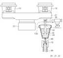
도 1은 본 발명의 실시 예에 따른 노즐 결합장치 및 용융물 처리설비의 개략도.
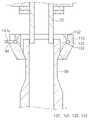
도 2는 본 발명의 실시 예에 따른 노즐 결합장치의 단면도.
도 3은 본 발명의 실시 예에 따른 노즐 결합장치의 분해사시도.
도 4는 가스통로 및 조절부의 구조를 나타내는 도면.
도 5는 플레이트 및 패킹블록의 구조를 나타내는 도면.
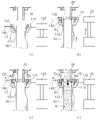
도 6은 제1 노즐과 제2 노즐로 용융물을 공급하는 모습을 나타내는 도면.
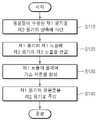
도 7은 본 발명의 실시 예에 따른 용융물 처리방법을 나타내는 플로우차트.1 is a schematic view of a nozzle coupling device and a melt processing facility according to an embodiment of the present invention.
2 is a cross-sectional view of a nozzle coupling device according to an embodiment of the present invention.
3 is an exploded perspective view of a nozzle coupling device according to an embodiment of the present invention.
4 is a view showing the structure of the gas passage and the control unit.
5 is a view showing the structure of the plate and the packing block.
6 is a view showing a state of supplying the melt to the first nozzle and the second nozzle.
7 is a flowchart illustrating a method for processing a melt according to an embodiment of the present invention.
이하, 첨부된 도면을 참조하여 본 발명의 실시예를 더욱 상세히 설명하기로 한다. 그러나 본 발명은 이하에서 개시되는 실시예에 한정되는 것이 아니라 서로 다른 다양한 형태로 구현될 것이며, 단지 본 실시예는 본 발명의 개시가 완전하도록 하며, 통상의 지식을 가진 자에게 발명의 범주를 완전하게 알려주기 위해 제공되는 것이다. 발명을 상세하게 설명하기 위해 도면은 과장될 수 있고, 도면상에서 동일 부호는 동일한 요소를 지칭한다.Hereinafter, embodiments of the present invention will be described in more detail with reference to the accompanying drawings. However, the present invention is not limited to the embodiments disclosed below, but will be implemented in various different forms, only this embodiment allows the disclosure of the present invention to be complete, and the scope of the invention to those of ordinary skill in the art completely It is provided to inform you. In order to explain the invention in detail, the drawings may be exaggerated, and like numerals refer to like elements in the drawings.
본 발명의 실시 예에 따른 노즐 결합장치는, 제1 노즐에 제2 노즐을 결합시킬 수 있는 장치에 관한 것이다. 보다 구체적으로, 제1 노즐을 향해 가스를 분사하여, 제1 노즐과 제2 노즐이 결합된 부분으로 공기가 유입되는 것을 방지할 수 있는 노즐 결합장치에 관한 것이다.A nozzle coupling device according to an embodiment of the present invention relates to a device capable of coupling a second nozzle to a first nozzle. More specifically, by injecting gas toward the first nozzle, it relates to a nozzle coupling device capable of preventing air from flowing into a portion where the first nozzle and the second nozzle are coupled.
본 발명의 실시 예에 따른 용융물 처리설비 및 노즐 체결 장치는 복수의 노즐을 이용하여 제1 용기에서 제2 용기로 용융물을 공급하는 다양한 처리설비에 적용될 수 있다. 이하에서는, 제철소의 제선공정 및 제강공정 등에 사용되는 처리설비를 기준으로 하여 실시 예를 설명한다. 여기서, 제1 용기는 용강을 수용할 수 있는 래들(Ladle)일 수 있고, 제2 용기는 용강을 공급받을 수 있는 턴디쉬(Tundish)일 수 있다. 또한, 제1 노즐은 콜렉터 노즐(Collector nozzle)일 수 있고, 제2 노즐은 쉬라우드 노즐(Shroud nozzle)일 수 있다. 또한, 분사되는 가스는 불활성 가스 중 예컨데, 아르곤(Ar) 가스일 수 있다. 하지만, 제1 용기, 제2 용기, 제1 노즐, 제2 노즐 및 가스는 이에 한정되지 않고 다양할 수 있다.The melt treatment facility and the nozzle fastening apparatus according to an embodiment of the present invention may be applied to various treatment facilities for supplying the melt from the first container to the second container using a plurality of nozzles. Hereinafter, an embodiment will be described on the basis of processing equipment used in a steelmaking process and a steelmaking process of a steel mill. Here, the first container may be a ladle capable of accommodating molten steel, and the second container may be a tundish capable of receiving molten steel. In addition, the first nozzle may be a collector nozzle, and the second nozzle may be a shroud nozzle. In addition, the injected gas may be, for example, argon (Ar) gas among inert gases. However, the first container, the second container, the first nozzle, the second nozzle, and the gas are not limited thereto and may be various.
도 1은 본 발명의 실시 예에 따른 노즐 결합장치 및 용융물 처리설비의 개략도이다.1 is a schematic view of a nozzle coupling device and a melt processing facility according to an embodiment of the present invention.
우선, 도 1을 참조하여, 본 발명의 실시 예에 따른 노즐 결합장치가 적용되는 용융물 처리설비에 관해 먼저 설명한다.First, with reference to FIG. 1, a melt processing facility to which a nozzle coupling device according to an embodiment of the present invention is applied will be first described.
본 발명의 실시 예에 따른 용융물 처리설비, 용융물(M)이 수용될 수 있는 제1 용기(10), 터렛(20), 제1 노즐(30), 제2 용기(40) 및 제2 노즐(50), 제3 노즐(60), 주형(70) 및 핀치롤(80)을 포함할 수 있다. 이에 더하여, 용융물 처리설비는 노즐 결합장치(100)를 포함할 수 있다.A melt processing facility according to an embodiment of the present invention, a
제1 용기(10)는 전로 정련을 마친 용융물(M)을 수강하여 제2 용기(40)에 제공할 수 있다.The
터렛(20)은 제2 용기(40) 상에 서로 다른 제1 용기(10)가 위치할 수 있도록, 제1 용기(10)를 회전시킬 수 있다. 터렛(20)은 지지 타워(21) 및 스윙 타워(22)를 포함할 수 있다. 지지 타워(21)에는 복수개의 제1 용기(10)가 안착될 수 있다. 스윙 타워(22)는 지지 타워(21)를 축 회전시킬 수 있다.The turret 20 may rotate the
제1 노즐(30)은 제1 용기(10)의 용융물(M)을 제2 용기(40)로 공급하는 통로 역할을 할 수 있다. 제1 노즐(30)은 제1 용기(10)의 하부에 설치되며, 상하방향으로 연장되고 중심부가 관통된 관 형상으로 마련될 수 있다. 제1 노즐(30)은 제2 노즐(50)에 삽입되며, 제2 노즐(50)에 결합될 수 있다.The
제2 용기(40)는 제1 용기(10)의 하부에 배치될 수 있으며, 제1 용기(10)로부터 출강된 용융물(M)을 공급받을 수 있다. 여기서, 제2 용기(40)는 제1 노즐(30) 및 제2 노즐(50)을 통해 공급되는 용융물(M)을 수용할 수 있다.The
제2 노즐(50)은 제1 노즐(30)에서 공급된 용융물(M)을 제2 용기(40)로 공급하는 통로 역할을 할 수 있다. 제2 노즐(50)은 상하방향으로 연장되고, 중심부가 관통될 수 있다. 제2 노즐(50)은 후술하는 노즐 결합장치(100)에 의해 지지될 수 있고, 지지된 상태에서 제1 노즐(30)의 하부에 결합될 수 있다. 즉, 제2 노즐(50)의 내부로 제1 노즐(30)이 삽입되며 제1 노즐(30)과 결합될 수 있다.The
제3 노즐(60)은 제2 용기(40)의 하부에 설치되며, 제2 용기(40)의 용융물(M)을 주형(70)으로 공급하는 통로 역할을 할 수 있다.The
주형(70)은 제3 노즐(60)로부터 공급된 용융물(M)을 응고시킬 수 있다. 주형(70)은 제2 용기(40)의 하측에 배치되고, 제3 노즐(60)을 하부를 감싸도록 배치될 수 있다.The
핀치롤(80)은 용융물(M)이 응고되어 형성된 주편이 인발되는 경로를 형성할 수 있다. 핀치롤(80)은 주형(70)의 하측에 나란하게 배치될 수 있다. 상술한 제1 용기(10), 터렛(20), 제1 노즐(30), 제2 용기(40), 제2 노즐(50), 제3 노즐(60), 주형(70) 및 핀치롤(80)은 제철소에 적용되는 일반적인 구성이므로, 특정한 구성으로 한정하지 않는다.The
도 2는 본 발명의 실시 예에 따른 노즐 결합장치의 단면도이고, 도 3은 본 발명의 실시 예에 따른 노즐 결합장치의 분해사시도이다. 하기에서는 도 1 내지 도 3을 참조하여, 본 발명의 실시 예에 따른 노즐 결합장치(100)에 관해 구체적으로 설명한다.2 is a cross-sectional view of a nozzle coupling device according to an embodiment of the present invention, Figure 3 is an exploded perspective view of the nozzle coupling device according to an embodiment of the present invention. Hereinafter, with reference to FIGS. 1 to 3, the
본 발명의 실시 예에 따른 노즐 결합장치(100)는 제1 노즐(30)에 제2 노즐(50)을 결합하기 위한 장치로서, 제2 노즐(50)이 안착될 수 있도록 중심부가 상하로 관통되는 안착부(110), 안착부(110)를 제1 노즐(30)을 향해 이동시킬 수 있도록 안착부(110)를 지지하는 구동부(120) 및 제1 노즐(30)을 향해 가스를 분사할 수 있도록 적어도 일부가 경사지게 안착부(110) 내에 형성되는 가스통로(130)을 포함할 수 있다. 또한, 노즐 결합장치(100)는 가스통로(130)로 가스를 공급하기 위한 공급부(140) 및 가스통로(130)로 공급되는 가스의 공급량을 조절할 수 있는 조절부(150)를 더 포함할 수 있다.The
안착부(110)는 제2 노즐(50)이 안착되며, 제2 노즐(50)을 지지할 수 있다. 안착부(110)는 중심부가 상하방향으로 관통되며, 상하방향을 기준으로 상부에서 하부를 향해 내경이 점차 감소하는 형상으로 마련될 수 있다. 예를 들어, 안착부(110)는 원주방향으로 연장되고, 상하방향으로 소정의 높이를 갖는 링 형상으로 마련될 수 있다. 여기서, 원주방향은 상하방향을 중심축으로 하는 원의 둘레방향일 수 있다.The
안착부(110)의 중심부에는 제2 노즐(50)이 안착될 수 있다. 보다 상세하게는 안착부(110)의 중심부 중 내경이 감소하는 부분에 제2 노즐(50)이 지지될 수 있다. 한편, 안착부(110)의 내부에는 가스통로(130)가 형성될 수 있다. 여기서, 가스통로(130)는 후술하는 제1 안착부몸체(111) 및 제2 안착부몸체(112)에 각각 형성될 수 있다. 안착부(110)는 제1 안착부몸체(111), 제2 안착부몸체(112) 및 연결튜브(113)를 포함할 수 있다.The
제1 안착부몸체(111)는 공급부(140) 및 구동부(120)에 각각 연결되며, 안착부(110)의 몸체를 이루는 일부분일 수 있다. 여기서, 제1 안착부몸체(111)는 제2 안착부몸체(112)보다 원주방향에 대한 길이가 더 길게 형성될 수 있다. 예를 들어, 제1 안착부몸체(111)는 편자 형상으로 마련될 수 있다.The first
또한, 제1 안착부몸체(111)는 양측에 결합돌기(111a)를 구비할 수 있다. 제1 안착부몸체(111)의 결합돌기(111a)가 후술하는 구동부(120)의 홀(121)에 삽입되며 제1 안착부몸체(111)가 구동부(120)와 결합될 수 있다.In addition, the first
제2 안착부몸체(112)는 제1 안착부몸체(111)와 함께 안착부(110)의 몸체를 이루는 나머지 부분일 수 있다. 여기서, 제2 안착부몸체(112)는 제1 안착부몸체(111)보다 원주방향에 대한 길이가 더 짧게 형성될 수 있다. 제2 안착부몸체(112)는 제1 안착부몸체(111)에 회전 가능하게 결합될 수 있다. 즉, 제2 안착부몸체(112)는 원주방향을 기준으로 제1 안착부몸체(111)의 개방된 부분에 결합될 수 있다. 여기서, 제2 안착부몸체(112)는 힌지 방식으로 제1 안착부몸체(111)에 결합될 수 있다. 이때, 제2 안착부몸체(112)는 회전시 제1 안착부몸체(111)와 간섭되지 않도록, 양단부가 내측으로 함몰되어 형성될 수 있다.The second seating part body 112 may be the remaining part constituting the body of the
연결튜브(113)는 내부에 가스가 이동 가능하고, 제1 안착부몸체(111)의 가스통로(130) 및 제2 안착부몸체(112)의 가스통로(130)에 각각 연결될 수 있다. 여기서, 연결튜브(113)는 신장수축 가능한 재질로 마련되고, 적어도 일부가 플랙시블하게 형성될 수 있다. 예를 들어, 연결튜브(113)는 주름관 형태로 형성될 수 있다. 연결튜브(113)를 통해, 제1 안착부몸체(111)의 가스통로(130)에 공급된 가스를 제2 안착부몸체(112)의 가스통로(130)로 공급할 수 있다.The connection tube 113 may move gas therein, and may be respectively connected to the gas passage 130 of the
구동부(120)는 안착부(110)를 제1 노즐(30)을 향해 이동시킬 수 있다. 구동부(120)는 단부에 관통된 홀(121)을 구비하며, 관통된 홀(121)에 상술한 결합돌기(111a)가 삽입될 수 있다. 또한, 구동부(120)는 적어도 일부가 상하방향으로 이동 가능하게 형성되며, 상승 이동하며 안착부(110) 및 제2 노즐(50)을 제1 노즐(30)을 향해 이동시킬 수 있다. 이에, 구동부(120)를 통해 제2 노즐(50)이 제1 노즐(30)에 결합될 수 있다. 예를 들어, 구동부(120)는 매니퓰레이터(Manipulator)일 수 있다.The driving
도 4는 가스통로 및 조절부의 구조를 나타내는 도면이다.4 is a view showing the structure of the gas passage and the control unit.
도 3 및 도 4를 참조하면, 가스통로(130)는 제1 노즐(30)을 향해 가스를 분사할 수 있도록, 적어도 일부가 경사지게 안착부(110) 내에 형성될 수 있다. 즉, 가스통로(130)는 공급부(140)에서 공급된 가스가 이동하기 위한 통로 및 이동한 가스가 분사되기 위한 통로일 수 있다. 가스통로(130)를 통해 분사된 가스는 제1 노즐(30)과 제2 노즐(50)이 결합된 부분을 상측에서 커버할 수 있다. 여기서, 제1 노즐(30)과 제2 노즐(50)이 결합된 부분은 제1 노즐(30)의 하단부가 제2 노즐(50)의 상단부에 삽입된 부분으로서, 제1 노즐(30)의 하단부와 제2 노즐(50)의 상단부가 중첩되는 부분일 수 있다.Referring to FIGS. 3 and 4 , at least a portion of the gas passage 130 may be formed in the
일반적으로, 제1 노즐(30)이 제2 노즐(50)에 삽입되면, 제2 노즐(50)의 내벽과 제1 노즐(30)의 외벽 사이에 소정의 틈이 발생할 수 있다. 제1 용기(10)에서 제2 용기(40)로 용융물(M)을 공급하면, 용융물(M)을 공급받는 제2 용기(40)의 내부에는 부압이 발생될 수 있고, 제1 노즐(30)과 제2 노즐(50) 사이의 틈으로 공기(예컨데, 산소(O2))가 유입될 수 있다. 이에, 가스통로(130)를 통해 가스를 분사하여 제1 노즐(30)의 둘레에, 구체적으로는 제1 노즐(30)과 제2 노즐(50)이 결합된 부분의 상부 둘레에 가스 커튼을 형성하므로, 제1 노즐(30)과 제2 노즐(50) 사이의 틈으로 공기가 유입되는 것을 방지할 수 있다. 가스를 통해, 공기의 유입을 차단하는 것과 관련된 설명은 하기에서 구체적으로 다시 설명한다. 가스통로(130)는 이동로(131) 및 제1 분사로(132)를 포함할 수 있다. 이에 더하여, 가스통로(130)는 제2 분사로(133)를 더 포함할 수 있다.In general, when the
도 3을 참조하면, 이동로(131)는 공급부(140)에서 공급된 가스를 제1 분사로(132)로 공급하기 위한 중간 통로일 수 있다. 이동로(131)는 안착부(110)의 내부에서 원주방향을 따라 연장되어 형성될 수 있다. 여기서, 이동로(131)는 제1 안착부몸체(111)와 제2 안착부몸체(112)에 각각 형성될 수 있다. 상술한 바와 같이, 제1 안착부몸체(111)의 이동로(131) 및 제2 안착부몸체(112)의 이동로(131)는 연결튜브(113)에 의해 서로 연결될 수 있다. 이에, 제1 안착부몸체(111)의 이동로(131)에 공급된 가스가 연결튜브(113)를 통과하여 제2 안착부몸체(112)의 이동로(131)로 공급될 수 있다.Referring to FIG. 3 , the
한편, 제1 안착부몸체(111)의 이동로(131)와 제2 안착부몸체(112)의 이동로(131)는 각각 양단부가 외부로 노출되게 형성될 수 있다. 즉, 제1 안착부몸체(111)의 이동로(131)의 양단부에서 배출된 가스가 제2 안착부몸체(112)의 이동로(131)의 양단부로 유입될 수 있다. 이에, 연결튜브(131) 없이도, 제1 안착부몸체(111)의 이동로(131)에서 제2 안착부몸체(112)의 이동로(131)로 가스를 공급할 수 있다.Meanwhile, the
도 4를 참조하면, 제1 분사로(132)는 이동로(131)에서 공급된 가스를 제1 노즐(30)의 둘레를 향해 분사하기 위한 분사 통로일 수 있다. 제1 분사로(132)는 이동로(131)에 연통되고, 안착부(110)의 내부에서 제1 노즐(30)을 향하여 상향 경사지게 형성될 수 있다. 또한, 제1 분사로(132)는 가스를 배출하는 배출단부가 안착부(110)의 상부에 노출될 수 있다.Referring to FIG. 4 , the
또한, 제1 분사로(132)는 제1 노즐(30)의 둘레를 향해 가스를 분사할 수 있도록, 안착부(110)에서 원주방향을 따라 형성될 수 있다. 예를 들어, 제1 분사로(132)는 원주방향을 따라 연장된 슬릿 형상으로 마련되거나, 혹은 원주방향을 따라 이격된 복수의 홀 형상으로 마련될 수 있다. 본 발명의 실시 예에서는 제1 분사로(132)가 원주방향을 따라 이격된 복수의 홀 형상으로 마련된 경우를 예시적으로 설명한다.In addition, the
상술한 바와 같이, 제1 분사로(132)는 제1 노즐(30)을 향해 상향 경사진 복수의 홀로 마련될 수 있으며, 제1 분사로(132)의 배출단부의 높이는 제1 노즐(30)과 제2 노즐(50)이 결합된 부분의 높이보다 높게 형성될 수 있다. 이에, 제1 분사로(132)에서 분사되는 가스가 제1 노즐(30)과 제2 노즐(50)이 결합된 부분의 상부에서 가스 커튼을 형성하여, 결합된 부분을 커버할 수 있다. 이에, 가스 커튼에 의해 결합된 부분 상부의 소정 영역이 커버되며, 외부 공기가 결합된 부분으로 유입되는 것을 차단할 수 있다. 여기서, 가스 커튼을 형성하는 가스는 다른 물질과 접촉하며 화학반응을 일으키기 어려운 불활성 가스일 수 있다. 즉, 가스 커튼을 형성하는 가스는 화학 반응성이 낮은 불활성의 가스일 수 있다. 예를 들어, 가스는 아르곤 가스(Ar), 질소 가스(N2) 등을 포함할 수 있다.As described above, the
한편, 제1 분사로(132)는 수평면을 기준으로 제1 노즐(30)을 향하여 상향 경사지게 형성될 수 있다. 제1 분사로(132)의 상향 경사진 각도(α)는 60°내지 70°로 형성될 수 있다. 여기서, 제1 분사로(132)의 경사진 각도(α)가 60°미만으로 형성될 경우, 제1 노즐(30)과 제2 노즐(50)이 결합된 부분보다 높은 위치에 배출단부가 효율적으로 도달하지 못할 수 있다. 또한, 제1 분사로(132)의 경사진 각도(α)가 70°초과로 형성될 경우, 가스 커튼이 커버할 영역(즉, 상술한 결합된 부분 상부의 소정 영역)이 증가하게 되므로, 더 많은 양의 가스로 가스 커튼을 형성해야 한다. 이에, 제1 분사로(132)의 상향 경사진 각도(α)를 60°내지 70°로 형성하여, 배출단부가 결합된 부분보다 높은 위치에 형성되게 하고, 결합된 부분에 최대한 인접하게 가스를 분사하여 가스 커튼이 커버해야 하는 영역(즉, 상술한 결합된 부분 상부의 소정 영역)을 최소화할 수 있다. 이에, 상대적으로 적은 양의 가스를 분사하여 가스 커튼을 형성할 수 있고, 결합된 부분을 효과적으로 커버할 수 있다.On the other hand, the
또한, 제1 분사로(132)는 가스가 배출되는 배출단부를 향하여 직경이 점차 증가할 수 있다.In addition, the diameter of the
일반적으로, 유체는 동일한 유량일 때 통과하는 단면적이 넓을수록 이동속도가 느리게 형성될 수 있다. 이에, 제1 분사로(132)에서 배출단부를 향하여 직경의 크기를 점차 크게 형성하므로, 배출단부에서 배출되는 가스의 이동속도를 상대적으로 감소시킬 수 있다. 이에, 제1 분사로(132)의 배출단부에서 배출되는 가스의 이동속도를 감소시켜, 안착부(120)의 상부로 분사된 가스를 정체시킬 수 있다. 이에, 정체된 가스가 안착부(110)의 상부 및 제1 노즐(30)의 둘레에 부유하며, 가스 커튼을 더 효과적으로 형성할 수 있다.In general, when a fluid has the same flow rate, the larger the cross-sectional area it passes through, the slower the moving speed may be. Accordingly, since the diameter of the
또한, 제1 분사로(132)에서 직경이 증가하는 내벽의 서로 마주보는 부분 사이의 확장 각도(β)는 110°내지 130°로 형성될 수 있다. 즉, 제1 분사로(132)의 배출단부 내벽 중 서로 마주보는 부분 사이의 각도(β)가 110°내지 130°로 형성될 수 있다. 여기서, 제1 분사로(132)의 배출단부 내벽 중 서로 마주보는 부분 사이의 각도(β)가 110°미만으로 형성될 경우, 분사되는 가스의 이동속도를 효과적으로 감소시키지 못할 수 있다. 또한, 제1 분사로(132)의 배출단부 내벽 중 서로 마주보는 부분 사이의 각도(β)가 130°초과로 형성될 경우, 배출단부 내에서 가스의 와류가 발생하여 안착부(120)의 상부로 가스가 원활하게 배출되지 못할 수 있다. 이에, 제1 분사로(132)의 배출단부 내벽 중 서로 마주보는 부분 사이의 각도(β)를 110°내지 130°로 형성하여, 배출단부 내에서 가스의 와류를 발생시키지 않고, 분사되는 가스의 이동속도를 효과적으로 감소시킬 수 있다.In addition, the expansion angle β between opposing portions of the inner wall of which the diameter increases in the
제2 분사로(133)는 이동로(131)로부터 공급된 가스를 제2 노즐(50)의 둘레를 향해 분사하기 위한 통로일 수 있다. 제2 분사로(133)는 이동로(131)에 연통되고, 안착부(110)의 내부에서 제2 노즐(50)을 향하여 하향 경사지게 형성될 수 있다. 제2 분사로(133)는 가스를 배출하는 배출단부가 안착부(110)의 중심부를 향하여 노출될 수 있다. 여기서, 안착부(110)의 중심부는 안착부(110)에서 상하방향으로 관통된 영역일 수 있다. 구체적으로, 배출단부는 관통 영역 내벽에 형성될 수 있다. 즉, 안착부(110)의 상하방향을 기준으로 관통역역의 중간 부분에 노출될 수 있다. 안착부(110)의 상하방향 길이를 기준으로 1/2에 해당하는 관통 영역 내벽에 형성될 수 있다. 또한, 제2 분사로(133)의 배출단부의 높이는 제1 노즐(30)과 제2 노즐(50)이 결합된 부분의 높이보다 낮게 형성될 수 있다. 또한, 제2 분사로(133)는 제2 노즐(50)의 둘레를 향해 가스를 분사할 수 있도록, 안착부(110)에서 원주방향을 따라 형성될 수 있다. 예를 들어, 제2 분사로(133)는 원주방향을 따라 연장된 슬릿 형상으로 마련되거나, 혹은 원주방향을 따라 이격된 복수의 홀 형상으로 마련될 수 있다. 본 발명의 실시 예에서는 제2 분사로(133)가 안착부(110)의 원주방향을 따라 이격된 복수의 홀로 마련된 경우를 예시적으로 설명한다.The
이처럼 제2 분사로(133)가 형성되면 제2 분사로(133)에서 분사되는 가스를 통해, 제2 노즐(50)이 안착된 안착부(110)의 중심부에 가스가 충진되어 가스 분위기가 형성될 수 있다. 즉, 안착부(110)의 관통 영역을 가스로 충진할 수 있다. 상세히 설명하면, 안착부(110)의 내주면과 안착부(110)에 안착된 제2 노즐(50)의 사이의 공간을 가스로 충진할 수 있다. 제1 노즐(30)과 제2 노즐(50)이 결합된 부분의 둘레에 가스 분위기를 형성할 수 있고, 외부 공기가 제1 노즐(30)과 제2 노즐(50)이 결합된 부분으로 유입되는 것을 억제할 수 있다.As such, when the
또한, 제2 분사로(133)는 수평면을 기준으로 제2 노즐(50)을 향하여 하향 경사지게 형성될 수 있다. 제2 분사로(133)의 하향 경사진 각도(γ)는 20°내지 30°로 형성될 수 있다. 여기서, 제2 분사로(133)의 경사진 각도(γ)가 20°미만으로 형성될 경우, 제1 노즐(30)과 제2 노즐(50)이 결합된 부분보다 낮은 위치에 배출단부가 효율적으로 도달하지 못할 수 있다. 또한, 제1 분사로(132)의 경사진 각도(γ)가 30°초과로 형성될 경우, 안착부(110)의 중심부와 연통되는 위치에 배출단부가 효율적으로 도달하지 못할 수 있다. 이에, 제2 분사로(133)의 하향 경사진 각도(γ)를 20°내지 30°로 형성하여, 제1 노즐(30)과 제2 노즐(50)이 결합된 부분보다 낮은 위치에 배출단부가 마련되게 하고, 중심부와 연통되는 위치에 배출단부가 마련되게 할 수 있다. 이에, 안착부(110)의 중심부로 원활하게 가스를 유입시키면서, 제1 노즐(30)과 제2 노즐(50)이 결합된 부분의 둘레에 가스 분위기를 형성할 수 있다.In addition, the
또한, 제2 분사로(133)는 가스가 배출되는 배출단부를 향하여 직경이 점차 증가하게 형성될 수 있다. 이에, 제2 분사로(133)의 배출단부에서 배출되는 가스의 이동속도를 감소시켜, 안착부(110)의 중심부로 분사된 가스를 정체시킬 수 있다. 이에, 정체된 가스가 안착부(110)의 하부에서부터 제1 노즐(30)과 제2 노즐(50)이 결합된 부분을 향해 충진될 수 있고, 결합된 부분의 둘레에 더 효과적으로 가스 분위기를 형성할 수 있다.In addition, the
또한, 제2 분사로(133)에서 직경이 증가하는 내벽의 서로 마주보는 부분 사이의 확장 각도(β)는 110°내지 130°로 형성될 수 있다. 즉, 제2 분사로(133)의 배출단부 내벽 중 서로 마주보는 부분 사이의 각도(β)가 110°내지 130°로 형성될 수 있다. 이에, 제2 분사로(133)의 배출단부 내벽 중 서로 마주보는 부분 사이의 각도(β)를 110°내지 130°로 형성하여, 배출단부 내에서 가스의 와류를 발생시키지 않으며, 분사되는 가스의 이동속도를 효과적하게 감소시킬 수 있다.In addition, the expansion angle β between opposing portions of the inner wall of which the diameter increases in the
도 5는 플레이트 및 패킹블록의 구조를 나타내는 도면이다.5 is a view showing the structure of the plate and the packing block.
도 5(a)를 참조하면, 가스통로(130)는 가스통로(130)의 내벽으로부터 돌출되는 플레이트(134)를 구비할 수 있다. 플레이트(134)는 제1 분사로(132) 및 제2 분사로(133) 중 적어도 어느 하나에 마련될 수 있다. 하기에서는 플레이트(134)가 제1 분사로(132) 및 제2 분사로(133)에 각각 마련된 경우를 예시적으로 설명하며, 제1 분사로(132)에 구비된 플레이트(134)를 기준으로 하여 플레이트(134)의 구조에 관해 설명한다.Referring to FIG. 5A , the gas passage 130 may include a
플레이트(134)는 가스의 이동방향으로 연장된 얇은 판 형상으로 형성될 수 있다. 플레이트(134)는 복수개로 마련되고, 제1 분사로(132)의 배출단부에서 배출단부의 둘레를 따라 이격 배치될 수 있다. 하기에서는 플레이트(134)가 4개로 마련되어 90°씩 이격된 경우를 예시적으로 설명한다.The
일반적으로, 와류는 흐르는 유체와 정지해 있는 유체가 접하는 경계면에서, 흐르는 유체가 정지해 있는 유체와 충돌하며 진행방향과 반대방향으로 돌게되는 현상을 지칭한다. 와류는 관의 내부에서 관의 외부로 유체가 배출될 때 혹은 유체가 이동하는 통로의 폭이 좁은 곳에서 넓은 곳으로 바뀌는 곳에서 발생할 수 있다. 만일, 제1 분사로(132)의 배출단부에서 와류가 발생될 경우, 배출단부 내에서 가스가 정체하며, 배출단부의 외부(즉, 안착부(110)의 상부)로 가스가 원활하게 배출되지 않을 수 있다. 이에, 제1 분사로(132)의 배출단부에 복수의 플레이트(134)를 설치하므로, 배출단부에서 와류가 발생되는 것을 억제 혹은 방지할 수 있다.In general, vortex refers to a phenomenon in which a flowing fluid collides with a stationary fluid at an interface between a flowing fluid and a stationary fluid and rotates in the opposite direction to the moving direction. A vortex may occur when the fluid is discharged from the inside of the pipe to the outside of the pipe, or where the width of the passage through which the fluid moves is changed from a narrow place to a wide place. If a vortex is generated at the discharge end of the
도 5(b)를 참조하면, 가스통로(130)는 가스가 통과될 수 있고, 제1 분사로(132)와 제2 분사로(133) 중 적어도 어느 하나의 배출단부에 삽입되는 패킹블록(135)을 구비할 수 있다. 하기에서는 패킹블록(135)이 제1 분사로(132) 및 제2 분사로(133)에 각가 마련된 경우를 예시적으로 설명하며, 제1 분사로(132)에 구비된 패킹블록(135)을 기준으로 하여 패킹블록(135)의 구조에 관해 설명한다.Referring to Figure 5 (b), the gas passage 130, the gas can pass, the
패킹블록(135)은 가스의 이동방향으로 관통될 수 있고, 가스의 이동방향으로 직경이 증가하는 중공의 원뿔대 형상으로 마련될 수 있다. 이때, 패킹블록(135)의 관통된 부분은 가스의 이동방향을 따라 내경이 증가할 수 있다. 제1 분사로(132)에 패킹블록(135)이 구비됨에 따라, 가스를 배출시키는 내경 크기를 상대적으로 감소시킬 수 있다. 이에, 배출단부의 내경의 크기를 조절하여 가스의 분사량을 상대적으로 감소시킬 수 있고, 상대적으로 적은 양으로 제1 노즐(30)의 둘레에 가스 커튼을 형성할 수 있다.The
공급부(140)는 가스통로(130)에 연통되도록, 안착부(110)에 결합되며, 가스통로(130)로 가스를 공급할 수 있다. 공급부(140)는 공급배관(141) 및 가스 생성부재(미도시)를 포함할 수 있다.The
공급배관(141)은 내부에 가스의 이동이 가능한 공급통로(141a)를 구비할 수 있다. 공급배관(141)은 일단이 안착부(110)의 제1 안착부몸체(111)에 삽입되어 제1 안착부몸체(111)의 이동로(131)에 연통되고, 타단이 가스 생성부재에 연결될 수 있다. 예를 들어, 공급배관(141)은 일방향으로 연장된 관 형상으로 형성될 수 있다. 가스 생성부재는 가스를 생성하며 생성된 가스를 공급배관(141)으로 공급할 수 있다.The
조절부(150)는 가스통로(130)로 공급되는 가스의 공급량을 조절할 수 있다. 조절부(150)는 개폐부재(151), 동력부재(미도시), 측정부재(152) 및 제어부재(153)를 포함할 수 있다.The adjusting unit 150 may adjust the amount of gas supplied to the gas passage 130 . The adjusting unit 150 may include an opening/closing
도 4를 참조하면, 개폐부재(151)는 복수개로 마련되며, 공급배관(141)의 내벽에 가스 이동방향에 대해 수직하게 직교하는 방향으로 이동할 수 있다. 복수의 개폐부재(151)는 적어도 일부가 공급통로(141a)의 중심부를 향해 회전 이동하며, 공급통로(141a)의 개방된 정도를 조절할 수 있다. 즉, 개폐부재(151)는 공급통로(141a)를 개폐할 수 있다. 예를 들어, 복수의 개폐부재(151)는 서로 중첩된 형태로 마련될 수 있다. 복수의 개폐부재(151)는 공급통로(141a)의 둘레를 감싸도록 배치될 수 있다. 복수의 개폐부재(151)는 가스가 이동하는 방향에 대하여 직교하는 방향을 따라 공급통로(141a)의 중심부로 이동할 수 있다. 이러한, 복수의 개폐부재(151)의 개폐방식은 카메라의 광의 노출량을 조절하는 조리개 구동방식에 일반적으로 적용되는 방식과 유사할 수 있다. 이에, 복수의 개폐부재(151)가 공급통로(141a)의 개구율을 증감시키며 가스통로(130)로 유입되는 가스의 양을 조절할 수 있다.Referring to FIG. 4 , a plurality of opening/closing
또한, 개폐부재(151)는 복수개로 마련되며, 공급배관(141)의 내벽에 힌지 방식으로 회전 가능하게 설치될 수도 있다. 즉, 복수의 개폐부재(151)는 회전 중심이 되는 일단부가 공급통로(141a)의 내벽에 고정되고, 타단부가 공급통로(141a)의 중심부로 이동하는 구조로 마련될 수 있다. 이러한, 복수의 개폐부재(151)의 개폐방식은 오리피스의 개폐방식에 일반적으로 적용되는 방식과 동일한 방식일 수 있다. 따라서, 복수의 개폐부재(151)가 공급통로(141a)를 개폐하며, 복수의 개폐부재(151)가 공급통로(141a)의 개구율을 증감시키며 가스통로(130)로 유입되는 가스의 양을 조절할 수 있다.In addition, the opening/closing
동력부재(미도시)는 복수의 개폐부재(151)를 이동시킬 수 있도록, 복수의 개폐부재(151)와 연결될 수 있다. 예를 들어, 동력부재는, 회전체, 모터, 제1 톱니, 제2 톱니, 및 제3 톱니를 포함할 수 있다. 회전체는 공급통로(141a)의 가장자리를 따라 회전 가능하게 설치될 수 있다. 즉, 회전체가 모터에서 발생되는 구동력을 제1 톱니 및 제2 톱니를 통해 전달받아, 회전하며 복수의 개폐부재(151)를 공급통로(141a)의 중심부를 향하여 회전 이동시킬 수 있다.The power member (not shown) may be connected to the plurality of opening and closing
측정부재(152)는 공급통로(141a)를 통과하는 가스 유량을 측정할 수 있다. 측정부재(152)는 가스의 이동방향을 기준으로 개폐부재(151)의 전단에 배치될 수 있다. 예를 들어, 측정부재(152)는 플로 센서로 마련되어, 공급통로(141a)를 통과하는 가스의 양을 측정할 수 있다. 한편, 측정부재(152)는 가스가 이동하는 공급통로(141a)의 내부 압력을 측정하여 가스의 유량을 측정할 수도 있다. 예를 들어, 측정부재(152)는 압력 센서로 마련되어 공급통로(141a)의 내부의 압력 변화를 통해 가스의 유량을 측정할 수 있다.The measuring
제어부재(153)는 측정부재(152) 및 개폐부재(151)에 각각 연결되고, 개폐부재(151)를 제어할 수 있다. 즉, 제어부재(153)는 개폐부재(151)를 제어하여, 공급통로(141a)의 개방된 정도를 증가시키거나 혹은 감소시킬 수 있다. 이에, 공급배관(141)에서 가스통로(130)로 공급되는 가스의 양을 제어할 수 있다.The
상기에서 설명한 노즐 결합장치(100)의 구성 요소들의 구조와 형상은 이에 한정되지 않고 다양할 수 있다.The structure and shape of the components of the
한편, 본 발명의 실시 예에 따른 노즐 결합장치(100)에서 가스를 분사하는 과정 은 용융물 처리방법을 설명하면서 그 과정을 함께 설명한다.On the other hand, the process of spraying the gas in the
하기에서는 본 발명의 실시 예에 따른 용융물 처리방법에 대해 설명하기로 한다. 하기에서는, 상술한 용융물 처리설비 및 노즐 결합장치(100)를 이용하여 용융물 처리방법을 실시하는 경우를 예시적으로 설명한다.Hereinafter, a method for processing a melt according to an embodiment of the present invention will be described. Hereinafter, a case in which the melt processing method is performed by using the above-described melt processing facility and the
도 6은 제1 노즐과 제2 노즐로 용융물을 공급하는 모습을 나타내는 도면이고, 도 7은 본 발명의 실시 예에 따른 용융물 처리방법을 나타내는 플로우차트이다.6 is a view showing a state of supplying a melt to the first nozzle and the second nozzle, Figure 7 is a flowchart showing a method for treating a melt according to an embodiment of the present invention.
도 1 내지 도 7을 참조하면, 본 발명의 실시 예에 따른 용융물 처리방법은 용융물(M)이 수용된 제1 용기(10)를 제2 용기(40)의 상측에 마련하는 과정(S110), 제1 용기(10)의 제1 노즐(30)에 제2 용기(40)의 제2 노즐(50)을 연결하는 과정(S120), 제1 노즐(30)의 둘레에 가스 커튼을 형성하는 과정(S130) 및 제1 용기(10)의 용융물(M)을 제2 용기(40)로 주입하는 과정(S140)을 포함할 수 있다.1 to 7, in the melt processing method according to an embodiment of the present invention, the process of providing the
여기서, 용융물(M)은 용강일 수 있고, 제1 용기(10)는 래들일 수 있으며, 제2 용기(40)는 턴디쉬일 수 있다. 또한, 제1 노즐(30)은 콜렉터 노즐일 수 있고, 제2 노즐(50)은 쉬라우드 노즐일 수 있으며, 가스는 불활성 가스(예컨데, 아르곤(Ar))일 수 있다. 하지만, 용융물(M), 제1 용기(10), 제2 용기(40), 제1 노즐(30), 제2 노즐(50) 및 가스의 적용범위는 이에 한정되지 않고 다양할 수 있다.Here, the melt M may be molten steel, the
도 6(a)를 참조하면, 용융물(M)이 수용된 제1 용기(10)를 제2 용기(40)의 상측에 마련할 수 있다(S110). 제1 용기(10)를 지지하는 터렛(20)을 회전시켜, 제2 용기(40)의 상측에 제1 용기(10)를 배치시킬 수 있다. 이때, 제1 용기(10)에 설치된 제1 노즐(30)이 제2 용기(40)에 설치된 제2 노즐(50)의 상측에 배치될 수 있다.Referring to FIG. 6( a ), the
한편, 제2 노즐(50)은 노즐 결합장치(100)의 안착부(110)에 안착되어 있는 상태일 수 있다. 즉, 제2 노즐(50)이 안착부(110)의 중심부에 삽입되어 안착부(110)의 내벽에 지지된 상태일 수 있다.On the other hand, the
도 6(b)를 참조하면, 제1 용기(10)의 제1 노즐(30)에 제2 용기(40)의 제2 노즐(50)을 연결시킬 수 있다(S120). 즉, 구동부(120)의 일부를 상승 이동시켜, 구동부(120)에 연결된 안착부(110)를 상승 이동시킬 수 있다. 이에, 안착부(110)와 함께 제2 노즐(50)이 상승하며 제1 노즐(30)에 결합될 수 있다. 여기서, 제2 노즐(50)의 내부로 제1 노즐(30)의 하부를 삽입시킬 수 있다. 이에, 제1 노즐(30)의 하단부와 제2 노즐(50)의 상단부가 중첩될 수 있으며, 중첩된 부분이 제1 노즐(30)과 제2 노즐(50)이 결합된 부분일 수 있다.Referring to FIG. 6B , the
도 6(c)를 참조하면, 제1 노즐(30)의 둘레에 가스 커튼을 형성할 수 있다(S130). 즉, 제1 노즐(30)과 제2 노즐(50)이 결합된 부분을 상측에서 커버할 수 있는 가스 커튼을 형성할 수 있다. 먼저, 공급부(140)의 가스 생성부재에서 가스를 생성하여 공급배관(141)으로 가스를 공급할 수 있다. 공급배관(141)으로 공급된 가스는 공급통로(141a)를 통해 제1 안착부몸체(111)의 가스통로(130)로 이동할 수 있다. 이후, 제1 안착부몸체(111)의 가스통로(130)로 공급된 가스는 연결튜브(113)를 통해 제2 안착부몸체(112)의 가스통로(130)로 공급될 수 있다.Referring to FIG. 6C , a gas curtain may be formed around the first nozzle 30 ( S130 ). That is, it is possible to form a gas curtain that can cover the portion where the
보다 구체적으로, 가스는 이동로(131)를 따라 안착부(110) 내에서 원주방향으로 이동할 수 있다. 이후, 가스는 제1 분사로(132) 및 제2 분사로(133)로 이동하여, 제1 분사로(132)를 통해 제1 노즐(30)을 향해 분사될 수 있고, 제2 분사로(133)를 통해 안착부(110)의 중심부로 분사될 수 있다.More specifically, the gas may move in the circumferential direction in the
제1 분사로(132)를 통해, 가스는 제1 노즐(30)의 둘레를 감싸도록 제1 노즐(30)을 향해 상향 경사지게 분사될 수 있다. 이때, 가스는 제1 노즐(30)과 상기 제2 노즐(50)이 결합된 부분의 상측으로 가스를 분사될 수 있다. 이에, 분사된 가스가 결합된 부분의 상측에서 가스 커튼을 형성하며 결합된 부분을 상측에서 커버할 수 있다.Through the
한편, 가스는 제1 분사로(132)에서 배출되면서 이동속도가 감소될 수 있다. 즉, 배출단부를 향해 직경이 증가하는 제1 분사로(132)를 통과하면서 가스의 이동속도가 감소될 수 있다. 이에, 분사되는 가스가 정체하며, 결합된 부분의 상측에 부유하게 될 수 있고, 결합된 부분의 상측에 가스 커튼을 더 효과적으로 형성할 수 있다.Meanwhile, while the gas is discharged from the
또한, 제2 분사로(133)를 통해 가스는 안착부(110)의 중심부로 분사될 수 있다. 즉, 가스는 제2 노즐(50)의 둘레를 감싸도록 제2 노즐(50)을 향해 하향 경사지게 분사될 수 있다. 또한, 가스는 제1 노즐(30)과 제2 노즐(50)이 결합된 부분의 하측으로 분사될 수 있다. 이에, 안착부(110)의 중심부에서 가스가 충진되고, 안착부(110)의 중심부 내에 가스 분위기가 형성될 수 있다. 즉, 결합된 부분의 하측에서부터 결합된 부분을 향하여 가스가 충진되고, 결합된 부분의 둘레에 가스 분위기를 형성할 수 있다.In addition, the gas may be injected into the center of the
한편, 제1 분사로(132) 및 제2 분사로(133)를 통해 가스를 분사함에 있어서, 플레이트(134)를 통해 제1 분사로(132) 및 제2 분사로(133)의 배출단부에서 와류가 발생하는 것을 억제시킬 수 있다. 이에, 제1 분사로(132)의 배출단부 및 제2 분사로(133)의 배출단부에서 가스를 원활하게 배출시킬 수 있다.On the other hand, when the gas is injected through the
한편, 안착부(110)로 가스를 공급하여 분사하는 과정은 제1 용기(10)의 용융물(M)을 제2 용기(40)로 공급하는 과정과 동시에 진행될 수도 있다.On the other hand, the process of supplying and spraying the gas to the
도 6(d)를 참조하면, 제1 용기(10)의 용융물(M)을 제2 용기(40)로 공급할 수 있다. 즉, 제1 노즐(30) 및 제2 노즐(50)을 통해 제1 용기(10)의 용융물(M)을 제2 용기(40)로 공급할 수 있다. 한편, 제1 용기(10)에서 제2 용기(40)로 용융물(M)을 공급하면, 용융물(M)을 공급받는 제2 용기(40)의 내부에는 부압이 발생될 수 있고, 제1 노즐(30)과 제2 노즐(50) 사이의 소정의 틈으로 공기가 유입되려 할 수 있다. 이때, 형성된 가스 커튼에 의해, 제1 노즐(30)과 제2 노즐(50) 사이의 소정의 틈으로 이동하는 공기가 차단될 수 있다. 또한, 결합된 부분의 둘레에 형성된 가스 분위기에 의해 소정의 틈으로 이동하는 공기가 밀려날 수 있다. 이에, 외부 공기가 제1 노즐(30)과 제2 노즐(50)이 결합된 부분으로 유입되는 것을 방지할 수 있고, 용융물(M)에 공기가 접촉하며 용융물(M)이 오염되는 것을 방지할 수 있다.Referring to FIG. 6( d ), the melt M of the
이처럼, 본 발명의 실시 예에 따르면, 제1 노즐을 향해 가스를 분사하여 가스 커튼을 형성할 수 있다. 이에, 제1 노즐과 제2 노즐이 결합된 부분으로 공기가 유입되는 것을 방지하여 용융물이 오염되는 것을 방지할 수 있다. 또한, 제2 노즐의 둘레에 가스를 분사하여 제1 노즐과 제2 노즐이 결합된 부분의 둘레에 가스 분위기를 형성할 수 있다. 이에, 공기가 결합된 부분으로 유입되는 것을 억제시킬 수 있다.As such, according to an embodiment of the present invention, a gas curtain may be formed by injecting gas toward the first nozzle. Accordingly, it is possible to prevent contamination of the melt by preventing air from flowing into the portion where the first nozzle and the second nozzle are coupled. In addition, a gas atmosphere may be formed around a portion where the first nozzle and the second nozzle are coupled by injecting the gas around the second nozzle. Accordingly, it is possible to suppress the inflow of air into the coupled portion.
이와 같이, 본 발명의 상세한 설명에서는 구체적인 실시예에 관해 설명하였으나, 본 발명의 범주에서 벗어나지 않는 한도 내에서 여러 가지 변형이 가능하다. 그러므로, 본 발명의 범위는 설명된 실시예에 국한되어 정해져서는 안 되며, 아래에 기재될 특허청구범위뿐만 아니라 이 청구범위와 균등한 것들에 의해 정해져야 한다.As such, although specific embodiments have been described in the detailed description of the present invention, various modifications are possible without departing from the scope of the present invention. Therefore, the scope of the present invention should not be limited to the described embodiments, but should be defined by the claims to be described below as well as the claims and equivalents.
100: 노즐 결합장치 110: 안착부
120: 구동부130: 가스통로
140: 공급부150: 조절부100: nozzle coupling device 110: seating part
120: driving unit 130: gas passage
140: supply unit 150: control unit
Claims (10)
Translated fromKorean상기 제2 노즐이 안착될 수 있도록, 중심부가 상하로 관통되는 안착부;
상기 안착부를 상기 제1 노즐을 향해 이동시킬 수 있도록, 상기 안착부를 지지하는 구동부; 및
상기 제1 노즐을 향해 가스를 분사할 수 있도록, 적어도 일부가 경사지게 상기 안착부 내에 형성되는 가스통로;를 포함하는 노즐 결합장치.A nozzle coupling device for coupling a second nozzle to a first nozzle, comprising:
a seating part through which the center penetrates up and down so that the second nozzle can be seated;
a driving part supporting the seating part so as to move the seating part toward the first nozzle; and
A nozzle coupling device comprising a; at least a portion of the gas passage is formed in the seating portion inclined so as to inject the gas toward the first nozzle.
상기 가스통로는,
상기 안착부의 내부에서 원주방향을 따라 연장되는 이동로; 및
상기 이동로에 연통되고, 가스가 배출되는 배출단부가 상기 안착부의 상부에 노출되는 제1 분사로;를 포함하는 노즐 결합장치.The method according to claim 1,
The gas passage,
a movement path extending in the circumferential direction from the inside of the seating part; and
A nozzle coupling device comprising a; a first injection path communicating with the movement path, the discharge end of which is exposed to the upper portion of the seating portion.
상기 제1 분사로는, 복수개로 마련되고, 상기 안착부의 원주방향을 따라 이격되며,
상기 제1 분사로의 배출단부의 높이는, 상기 제1 노즐과 상기 제2 노즐이 결합되는 높이보다 높은 노즐 결합장치.3. The method according to claim 2,
The first injection path, provided in plurality, is spaced apart along the circumferential direction of the seating portion,
The height of the discharge end of the first injection path is higher than a height at which the first nozzle and the second nozzle are coupled to each other.
상기 가스통로는, 상기 이동로에 연통되고 가스가 배출되는 배출단부가 상기 안착부의 중심부에 노출되는 제2 분사로;를 포함하는 노즐 결합장치.4. The method according to claim 2 or 3,
The gas passage, the second injection passage communicating with the movement passage and the discharge end of which gas is discharged is exposed to the center of the seating portion; nozzle coupling device comprising a.
상기 제1 분사로 및 상기 제2 분사로는, 각각의 배출단부를 향하여 직경이 점차 증가하게 형성되는 노즐 결합장치.5. The method according to claim 4,
The first injection path and the second injection path, the nozzle coupling device is formed to gradually increase in diameter toward each discharge end.
상기 가스통로는, 상기 가스통로의 내벽으로부터 돌출되는 플레이트;를 구비하는 노즐 결합장치.The method according to claim 1,
The gas passage includes a plate protruding from an inner wall of the gas passage.
상기 가스통로는, 가스가 통과될 수 있고, 상기 제1 분사로와 상기 제2 분사로의 배출단부에 삽입되는 패킹블록;이 구비되는 노즐 결합장치.5. The method according to claim 4,
The gas passage, through which gas can pass, a packing block inserted into the discharge ends of the first injection passage and the second injection passage; a nozzle coupling device provided with.
내부에 가스가 이동 가능한 공급통로를 구비하고, 상기 가스통로에 연결되는 공급부; 및
상기 가스통로로 공급되는 가스의 공급량을 조절할 수 있도록, 상기 공급부에 설치되는 조절부;를 더 포함하는 노즐 결합장치.4. The method according to any one of claims 1 to 3,
a supply unit having a supply passage through which gas can move therein and connected to the gas passage; and
The nozzle coupling device further comprising a; adjuster installed in the supply unit so as to adjust the supply amount of the gas supplied to the gas passage.
상기 조절부는,
상기 공급통로의 개방 정도를 조절할 수 있도록, 상기 공급통로의 중심부로 회전 이동 가능하게 상기 공급통로에 결합되는 개폐부재;
상기 공급통로의 가스 유량을 측정하기 위해, 가스의 이동방향을 기준으로 상기 개폐부재의 전단에 배치되는 측정부재; 및
상기 측정부재의 측정 결과에 따라, 가스의 유량을 제어할 수 있도록, 상기 개폐부재에 연결되는 제어부재;를 포함하는 노즐 결합장치.9. The method of claim 8,
The control unit,
an opening/closing member coupled to the supply passage to be rotatably movable toward the center of the supply passage so as to adjust the degree of opening of the supply passage;
a measuring member disposed at a front end of the opening/closing member based on a moving direction of the gas to measure the gas flow rate of the supply passage; and
A nozzle coupling device comprising a; control member connected to the opening and closing member so as to control the flow rate of the gas according to the measurement result of the measuring member.
상기 안착부는,
상기 구동부에 연결되는 제1 안착부몸체;
회전 가능하게 상기 제1 안착부몸체에 결합되는 제2 안착부몸체; 및
상기 제1 안착부몸체의 가스통로와 상기 제2 안착부몸체의 가스통로에 각각 연결되는 연결튜브;를 포함하는 노즐 결합장치.4. The method according to any one of claims 1 to 3,
The seating part,
a first seating unit body connected to the driving unit;
a second seating part body rotatably coupled to the first seating part body; and
A nozzle coupling device including a; connecting tube respectively connected to the gas passage of the first seat body and the gas passage of the second seat body.
Priority Applications (1)
| Application Number | Priority Date | Filing Date | Title |
|---|---|---|---|
| KR1020210052873AKR20220146057A (en) | 2021-04-23 | 2021-04-23 | Apparatus for coupling of nozzle and metohd for molten material using the same |
Applications Claiming Priority (1)
| Application Number | Priority Date | Filing Date | Title |
|---|---|---|---|
| KR1020210052873AKR20220146057A (en) | 2021-04-23 | 2021-04-23 | Apparatus for coupling of nozzle and metohd for molten material using the same |
Publications (1)
| Publication Number | Publication Date |
|---|---|
| KR20220146057Atrue KR20220146057A (en) | 2022-11-01 |
Family
ID=84042330
Family Applications (1)
| Application Number | Title | Priority Date | Filing Date |
|---|---|---|---|
| KR1020210052873APendingKR20220146057A (en) | 2021-04-23 | 2021-04-23 | Apparatus for coupling of nozzle and metohd for molten material using the same |
Country Status (1)
| Country | Link |
|---|---|
| KR (1) | KR20220146057A (en) |
Citations (1)
| Publication number | Priority date | Publication date | Assignee | Title |
|---|---|---|---|---|
| KR20040021971A (en) | 2002-09-06 | 2004-03-11 | 주식회사 포스코 | An apparatus for automatically connecting shroud nozzle to collector nozzle |
- 2021
- 2021-04-23KRKR1020210052873Apatent/KR20220146057A/enactivePending
Patent Citations (1)
| Publication number | Priority date | Publication date | Assignee | Title |
|---|---|---|---|---|
| KR20040021971A (en) | 2002-09-06 | 2004-03-11 | 주식회사 포스코 | An apparatus for automatically connecting shroud nozzle to collector nozzle |
Similar Documents
| Publication | Publication Date | Title |
|---|---|---|
| JP2019517392A (en) | Apparatus for treating molten material and method of treating molten material | |
| US4723997A (en) | Method and apparatus for shielding a stream of liquid metal | |
| US6070649A (en) | Method for pouring a metal melt into a mold | |
| KR101667674B1 (en) | Stopper | |
| NZ241288A (en) | Slag carryover prevented by floating refractory plug with mating | |
| KR20220146057A (en) | Apparatus for coupling of nozzle and metohd for molten material using the same | |
| JPH0323263B2 (en) | ||
| EP0089282B1 (en) | Process and device for the protection of a casting stream of liquid metal | |
| CA1239023A (en) | Method and apparatus for adding solid alloying ingredients to molten metal stream | |
| KR20130034323A (en) | Molten metal pouring apparatus made non-oxidation atmosphere in tundish | |
| US4005743A (en) | Apparatus for the continuous casting of metals especially steel, and method of continuously casting metals | |
| US4805688A (en) | Process for protecting against oxidation and/or nitridation of a liquid metal stream and device for carrying out the process | |
| KR101794598B1 (en) | Stopper | |
| EP4082689B1 (en) | Molten material treatment apparatus and method | |
| CA2112742C (en) | Machine and method of continuously casting a metal strip | |
| KR20230093868A (en) | Apparatus and method of monitoring nozzle | |
| KR101722952B1 (en) | Stopper | |
| KR101722951B1 (en) | Immersion nozzle | |
| KR20140140341A (en) | Stopper for continuous casting machine | |
| KR20150041953A (en) | Stopper | |
| KR20120027323A (en) | Method for operating a floor drain for use in a tank for metal melts | |
| KR101914089B1 (en) | Molten material processing apparatus and processing method | |
| KR100525600B1 (en) | A device for pouring the molten metal in continuous steel casting | |
| SU1553241A1 (en) | Arrangement for protecting molten metal jet | |
| KR101802006B1 (en) | Tube for pouring liquid metal, assembly of a tube and a metal frame and metal frame |
Legal Events
| Date | Code | Title | Description |
|---|---|---|---|
| PA0109 | Patent application | Patent event code:PA01091R01D Comment text:Patent Application Patent event date:20210423 | |
| PN2301 | Change of applicant | Patent event date:20220812 Comment text:Notification of Change of Applicant Patent event code:PN23011R01D | |
| PG1501 | Laying open of application | ||
| E902 | Notification of reason for refusal | ||
| PE0902 | Notice of grounds for rejection | Comment text:Notification of reason for refusal Patent event date:20250324 Patent event code:PE09021S01D |