KR20220145448A - Aircraft docking guidance system using 3D laser scanner and control method for the same - Google Patents
Aircraft docking guidance system using 3D laser scanner and control method for the sameDownload PDFInfo
- Publication number
- KR20220145448A KR20220145448AKR1020210051662AKR20210051662AKR20220145448AKR 20220145448 AKR20220145448 AKR 20220145448AKR 1020210051662 AKR1020210051662 AKR 1020210051662AKR 20210051662 AKR20210051662 AKR 20210051662AKR 20220145448 AKR20220145448 AKR 20220145448A
- Authority
- KR
- South Korea
- Prior art keywords
- aircraft
- information
- unit
- guidance system
- data
- Prior art date
- Legal status (The legal status is an assumption and is not a legal conclusion. Google has not performed a legal analysis and makes no representation as to the accuracy of the status listed.)
- Granted
Links
Images


Classifications
- G—PHYSICS
- G08—SIGNALLING
- G08G—TRAFFIC CONTROL SYSTEMS
- G08G5/00—Traffic control systems for aircraft
- G08G5/50—Navigation or guidance aids
- G08G5/56—Navigation or guidance aids for two or more aircraft
- G—PHYSICS
- G08—SIGNALLING
- G08G—TRAFFIC CONTROL SYSTEMS
- G08G5/00—Traffic control systems for aircraft
- G08G5/70—Arrangements for monitoring traffic-related situations or conditions
- G—PHYSICS
- G05—CONTROLLING; REGULATING
- G05D—SYSTEMS FOR CONTROLLING OR REGULATING NON-ELECTRIC VARIABLES
- G05D1/00—Control of position, course, altitude or attitude of land, water, air or space vehicles, e.g. using automatic pilots
- G05D1/0083—Control of position, course, altitude or attitude of land, water, air or space vehicles, e.g. using automatic pilots to help an aircraft pilot in the rolling phase
- G—PHYSICS
- G05—CONTROLLING; REGULATING
- G05D—SYSTEMS FOR CONTROLLING OR REGULATING NON-ELECTRIC VARIABLES
- G05D1/00—Control of position, course, altitude or attitude of land, water, air or space vehicles, e.g. using automatic pilots
- G05D1/02—Control of position or course in two dimensions
- G05D1/0202—Control of position or course in two dimensions specially adapted to aircraft
- G08G5/0043—
- B—PERFORMING OPERATIONS; TRANSPORTING
- B64—AIRCRAFT; AVIATION; COSMONAUTICS
- B64F—GROUND OR AIRCRAFT-CARRIER-DECK INSTALLATIONS SPECIALLY ADAPTED FOR USE IN CONNECTION WITH AIRCRAFT; DESIGNING, MANUFACTURING, ASSEMBLING, CLEANING, MAINTAINING OR REPAIRING AIRCRAFT, NOT OTHERWISE PROVIDED FOR; HANDLING, TRANSPORTING, TESTING OR INSPECTING AIRCRAFT COMPONENTS, NOT OTHERWISE PROVIDED FOR
- B64F1/00—Ground or aircraft-carrier-deck installations
- B64F1/002—Taxiing aids
- B—PERFORMING OPERATIONS; TRANSPORTING
- B64—AIRCRAFT; AVIATION; COSMONAUTICS
- B64F—GROUND OR AIRCRAFT-CARRIER-DECK INSTALLATIONS SPECIALLY ADAPTED FOR USE IN CONNECTION WITH AIRCRAFT; DESIGNING, MANUFACTURING, ASSEMBLING, CLEANING, MAINTAINING OR REPAIRING AIRCRAFT, NOT OTHERWISE PROVIDED FOR; HANDLING, TRANSPORTING, TESTING OR INSPECTING AIRCRAFT COMPONENTS, NOT OTHERWISE PROVIDED FOR
- B64F1/00—Ground or aircraft-carrier-deck installations
- B64F1/22—Ground or aircraft-carrier-deck installations for handling aircraft
- G—PHYSICS
- G01—MEASURING; TESTING
- G01S—RADIO DIRECTION-FINDING; RADIO NAVIGATION; DETERMINING DISTANCE OR VELOCITY BY USE OF RADIO WAVES; LOCATING OR PRESENCE-DETECTING BY USE OF THE REFLECTION OR RERADIATION OF RADIO WAVES; ANALOGOUS ARRANGEMENTS USING OTHER WAVES
- G01S17/00—Systems using the reflection or reradiation of electromagnetic waves other than radio waves, e.g. lidar systems
- G01S17/02—Systems using the reflection of electromagnetic waves other than radio waves
- G01S17/06—Systems determining position data of a target
- G01S17/08—Systems determining position data of a target for measuring distance only
- G—PHYSICS
- G01—MEASURING; TESTING
- G01S—RADIO DIRECTION-FINDING; RADIO NAVIGATION; DETERMINING DISTANCE OR VELOCITY BY USE OF RADIO WAVES; LOCATING OR PRESENCE-DETECTING BY USE OF THE REFLECTION OR RERADIATION OF RADIO WAVES; ANALOGOUS ARRANGEMENTS USING OTHER WAVES
- G01S17/00—Systems using the reflection or reradiation of electromagnetic waves other than radio waves, e.g. lidar systems
- G01S17/88—Lidar systems specially adapted for specific applications
- G01S17/89—Lidar systems specially adapted for specific applications for mapping or imaging
- G01S17/894—3D imaging with simultaneous measurement of time-of-flight at a 2D array of receiver pixels, e.g. time-of-flight cameras or flash lidar
- G—PHYSICS
- G01—MEASURING; TESTING
- G01S—RADIO DIRECTION-FINDING; RADIO NAVIGATION; DETERMINING DISTANCE OR VELOCITY BY USE OF RADIO WAVES; LOCATING OR PRESENCE-DETECTING BY USE OF THE REFLECTION OR RERADIATION OF RADIO WAVES; ANALOGOUS ARRANGEMENTS USING OTHER WAVES
- G01S7/00—Details of systems according to groups G01S13/00, G01S15/00, G01S17/00
- G01S7/48—Details of systems according to groups G01S13/00, G01S15/00, G01S17/00 of systems according to group G01S17/00
- G01S7/4802—Details of systems according to groups G01S13/00, G01S15/00, G01S17/00 of systems according to group G01S17/00 using analysis of echo signal for target characterisation; Target signature; Target cross-section
- G—PHYSICS
- G05—CONTROLLING; REGULATING
- G05D—SYSTEMS FOR CONTROLLING OR REGULATING NON-ELECTRIC VARIABLES
- G05D1/00—Control of position, course, altitude or attitude of land, water, air or space vehicles, e.g. using automatic pilots
- G05D1/40—Control within particular dimensions
- G05D1/46—Control of position or course in three dimensions
- G—PHYSICS
- G06—COMPUTING OR CALCULATING; COUNTING
- G06V—IMAGE OR VIDEO RECOGNITION OR UNDERSTANDING
- G06V10/00—Arrangements for image or video recognition or understanding
- G06V10/10—Image acquisition
- G—PHYSICS
- G08—SIGNALLING
- G08G—TRAFFIC CONTROL SYSTEMS
- G08G5/00—Traffic control systems for aircraft
Landscapes
- Engineering & Computer Science (AREA)
- Physics & Mathematics (AREA)
- General Physics & Mathematics (AREA)
- Aviation & Aerospace Engineering (AREA)
- Radar, Positioning & Navigation (AREA)
- Remote Sensing (AREA)
- Computer Networks & Wireless Communication (AREA)
- Electromagnetism (AREA)
- Mechanical Engineering (AREA)
- Automation & Control Theory (AREA)
- Theoretical Computer Science (AREA)
- Multimedia (AREA)
- Length Measuring Devices By Optical Means (AREA)
- Traffic Control Systems (AREA)
Abstract
Description
Translated fromKorean본 발명은 3차원 레이저 스캐너를 이용하여 항공기 주기유도 시스템 및 이를 이용한 항공기 주기 제어방법에 관한 것으로, 더욱 상세하게는 3차원 레이저 스캐너를 이용하여 항공기의 형태(전장, 전고, 동체 크기, 중심에 대한 각도 등), 위치, 거리정보, 기종 등의 정보를 이미 구축된 항공기 데이터 베이스(DB)를 활용한 디지털 정보처리기술로 분석하여 항공기 주기유도가 가능하도록 하는 시스템 및 이를 이용한 항공기 주기 제어방법에 관한 것이다.The present invention relates to an aircraft period guidance system using a three-dimensional laser scanner and an aircraft period control method using the same, and more particularly, to an aircraft shape (full length, total height, body size, center of gravity) using a three-dimensional laser scanner. Angle, etc.), location, distance information, and aircraft type, etc. are analyzed with digital information processing technology using an already-established aircraft database (DB) to enable aircraft parking guidance will be.
종래의 공항 활주로에 진입하는 항공기는 정확한 위치에 주기 하도록 유도하기 위해 마샬러(marshaller)가 수신호를 통하여 수동으로 항공기 조종사에게 항공기 진행방향과 정지위치 등을 지시하여 주기장소까지 유도하였다.In order to induce the aircraft entering the conventional airport runway to park at the correct position, a marshaler manually instructs the aircraft pilot in the direction and stop position of the aircraft through hand signals to guide them to the parking area.
하지만, 이러한 수동적인 주기유도 방법은 게이트가 많은 대형 공항에서는 항공기가 이착륙하는 경우에 특정한 계류장에서 문제나 장애가 발생하는 경우 공항 지휘본부에서 이에 대한 통보나 신속한 파악 및 조치가 어려우며, 다수의 주기 유도 인력으로 인한 인력확보 문제가 발생하고 있다.However, in this passive guiding method, it is difficult for the airport command center to notify or promptly identify and take action when a problem or failure occurs at a specific apron when aircraft take off and land at a large airport with many gates, and a large number of guiding personnel As a result, there is a problem of securing manpower.
이러한 상황들을 감안하여 개발한 종래의 항공기 기종식별기술로써, 대한민국 특허 10-0246556(발명의 명칭: 항공기 주기위치 지시시스템)은 CCD(Charge Coupled Device) 카메라, 표시부, 처리부 및 표시부로 구성되고, 항공기 계류장에서 CCD 카메라로 계류장으로 진입하는 항공기의 3차원 영상을 획득하여 항공기의 윤곽선만이 남게 영상을 처리한 후 항공기의 종류, 거리, 측방편위 등의 계산 결과를 디스플레이하는 항공기 시각주기유도시스템이다.As a conventional aircraft type identification technology developed in consideration of these circumstances, Korean Patent 10-0246556 (Title of the Invention: Aircraft Parking Position Indicating System) is composed of a CCD (Charge Coupled Device) camera, a display unit, a processing unit and a display unit, and the aircraft It is an aircraft visual cycle guidance system that acquires a three-dimensional image of an aircraft entering the apron with a CCD camera from the apron, processes the image so that only the outline of the aircraft remains, and then displays the calculation results such as the type, distance, and lateral deviation of the aircraft.
상기 항공기 주기위치 지시시스템은 CCD(Charge Coupled Device) 카메라를 사용하여 항공기의 화상 파일을 얻은 후 이미지 처리과정을 통하여 항공기의 외곽선을 인식하고 사전에 구축해 놓은 항공기 데이터베이스(DB)를 활용하여 거리 및 각도 변화의 시뮬레이션에 의한 결과를 토대로 획득된 실화상과 비교 후 일치하는 데이터에서 항공기를 찾아내어 기종을 판별하고, 항공기의 현재 거리 및 각도 등을 삼각법으로 계산하여 결과를 디스플레이 하는 항공기 주기위치 지시시스템이다.The aircraft parking position indication system uses a CCD (Charge Coupled Device) camera to obtain an image file of the aircraft, then recognizes the outline of the aircraft through an image processing process, and utilizes an aircraft database (DB) built in advance for distance and angle It is an aircraft parking position indication system that compares the actual image obtained based on the result of the simulation of change and then finds the aircraft in the matching data to determine the aircraft type, calculates the current distance and angle of the aircraft by trigonometry, and displays the result. .
따라서, 종래의 이미지 처리 방식은 햇빛, 안개, 우천, 우박 등의 날씨 등의 환경 영향에 의한 항공기 형태(전장, 전고, 동체 크기, 중심에 대한 각도 등), 위치, 거리정보, 기종 등의 정보 실시간으로 얻을 수 없으며, 기종의 정확한 판단을 전제로 하는 항공기 주기유도를 위한 정보제공에 어려움이 있다.Therefore, in the conventional image processing method, information such as aircraft shape (length, total height, body size, angle with respect to the center, etc.), location, distance information, model, etc. It cannot be obtained in real time, and there is a difficulty in providing information for guiding aircraft based on accurate judgment of the aircraft type.
본 발명은 상기와 같은 문제를 해결하기 위해 제안된 것으로, 3차원 레이저 스캐너를 이용하여 항공기의 형태(전장, 전고, 동체 크기, 중심에 대한 각도, 중심선 등), 위치, 거리정보, 기종 등의 정보를 실시간으로 획득하여 주기유도가 가능한 시스템 및 이를 이용한 항공기 주기 제어방법을 제공하는 것을 목적으로 한다.The present invention has been proposed to solve the above problems, and the shape (length, height, body size, angle to the center, center line, etc.) of the aircraft, location, distance information, model, etc. An object of the present invention is to provide a system capable of guiding the aircraft by acquiring information in real time and a method for controlling the aircraft period using the same.
본 발명에 따른 3차원 레이저 스캐너를 이용한 항공기 주기유도 시스템은 항공기의 주기유도 및 주기 제어와 연관된 데이터를 획득하는 레이저 스캔부; 상기 레이저 스캔부를 이용한 항공기 주기유도 및 주기 제어의 대상이 되는 항공기 기종별 규격 및 특징과 연관된 정보를 저장하는 데이터베이스부; 상기 레이저 스캔부와 데이터베이스부 사이에서 정보를 송수신하는 통신부; 및 상기 레이저 스캔부를 통해 획득한 영상정보와 상기 데이터베이스부에 저장된 정보를 비교하여 대상물의 정보를 판정하는 데이터분석 판정 알고리즘 처리부를 포함할 수 있다.Aircraft period guidance system using a three-dimensional laser scanner according to the present invention is a laser scanning unit for acquiring data related to the period guidance and period control of the aircraft; a database unit for storing information related to specifications and characteristics of each aircraft type to be subjected to aircraft period guidance and period control using the laser scan unit; a communication unit for transmitting and receiving information between the laser scanning unit and the database unit; and a data analysis determination algorithm processing unit that compares the image information acquired through the laser scanning unit with information stored in the database unit to determine the information of the object.
실시 예에 따르면, 상기 항공기 주기유도 시스템은 상기 데이터분석 판정 알고리즘 처리부에서 생성된 정보를 조종사 안내 표시기에 표시하는 디스플레이부; 및상기 디스플레이부에 송신된 정보를 기반으로 항공기 자동 제어가 가능하도록 하는 항공기 제어부를 포함할 수 있다.According to an embodiment, the aircraft main guidance system includes a display unit for displaying the information generated by the data analysis determination algorithm processing unit on the pilot guidance indicator; and an aircraft control unit configured to enable automatic aircraft control based on the information transmitted to the display unit.
실시 예에 따르면, 상기 레이저 스캔부는 레이저를 송출하고 상기 대상물에 의해 반사되는 레이저를 수신하는 레이저 송수신장치; 상기 레이저의 송신 시간 및 수신 시간으로부터 상기 대상물까지의 거리 측정이 가능한 거리측정장치; 및 상기 항공기의 중심선, 상기 항공기가 접현될 주기장을 스캔하여 영상 데이터를 생성하는 영상 데이터 스캔장치를 포함할 수 있다.According to an embodiment, the laser scanning unit includes a laser transceiver for transmitting a laser and receiving a laser reflected by the object; a distance measuring device capable of measuring the distance from the transmission time and reception time of the laser to the object; And it may include an image data scanning device for generating image data by scanning the center line of the aircraft and the aircraft stand where the aircraft is to be docked.
실시 예에 따르면, 상기 레이저 스캔부는 3D 스캐너로 상기 항공기의 진입이 예상되는 영역 내에서 오브젝트들의 특징적인 점군(point group)을 스캔하고, 상기 데이터분석 판정 알고리즘 처리부는 상기 스캔된 점군으로부터 상기 점군 간의 거리를 판단하여 오브젝트들을 생성하고, 상기 생성된 오브젝트들이 상기 항공기로 예상되는 일정 크기 이상의 오브젝트로 판단되면, 상기 항공기로 판단된 오브젝트들을 항공기 프로파일과 비교할 수 있다. 상기 항공기 프로파일은 항공기의 길이, 높이, 너비, 엔진간 거리, 엔진크기로 이루어진 항공기 제원에 관한 정보이다.According to an embodiment, the laser scanning unit scans a characteristic point group of objects in an area where the aircraft is expected to enter with a 3D scanner, and the data analysis decision algorithm processing unit is a 3D scanner between the point groups from the scanned point group. Objects are generated by determining the distance, and when the generated objects are determined to be objects of a predetermined size or larger expected to be the aircraft, the objects determined as the aircraft may be compared with the aircraft profile. The aircraft profile is information about aircraft specifications consisting of length, height, width, distance between engines, and engine size of the aircraft.
실시 예에 따르면, 상기 데이터분석 판정 알고리즘 처리부는 상기 항공기가 진입 시 엔진으로 예측되는 오브젝트를 기준으로 상기 엔진의 기울기를 판단하고, 상기 항공기의 코라고 예상되는 점을 기준으로 양쪽 엔진 위치에 형성된 점군의 개수를 확인하여 일정 수 이상이면, 상기 항공기의 해당 모델을 판단할 수 있다.According to an embodiment, the data analysis determination algorithm processing unit determines the inclination of the engine based on an object predicted to be the engine when the aircraft enters, and a point group formed at both engine positions based on a point expected to be the nose of the aircraft If the number is greater than or equal to a certain number by checking the number of , it is possible to determine the corresponding model of the aircraft.
실시 예에 따르면, 상기 항공기 제어부는 PDU (Pilot Display Unit)의 내부에 설치된 3축 센서를 이용하여 각 축에 해당하는 Pitch, Roll, Yaw 기울기 정보를 획득하고, 상기 획득된 기울기 정보를 초기값으로 상기 데이터베이스부에 저장하는 초기화 단계를 수행하고, 상기 PDU의 3축 센서를 이용하여 상기 각 축의 기울기 정보를 획득하여 상기 획득된 기울기 정보를 상기 초기값과 비교하여 허용치를 벗어나면, 상기 PDU를 통해 사용자에게 통보하고, 메인터턴스툴(MTT)을 이용하여 3D 스캐너의 3축을 보정하는 사용자 보정 단계를 수행할 수 있다.According to an embodiment, the aircraft control unit acquires pitch, roll, and yaw inclination information corresponding to each axis using a three-axis sensor installed inside a PDU (Pilot Display Unit), and sets the obtained inclination information as an initial value. Performing the initialization step of storing the data in the database unit, obtaining the inclination information of each axis using the 3-axis sensor of the PDU, comparing the obtained inclination information with the initial value, and if out of the allowable value, through the PDU The user may be notified and a user calibration step of calibrating 3 axes of the 3D scanner may be performed using a maintenance tool (MTT).
실시 예에 따르면, 상기 항공기 제어부는 PDU (Pilot Display Unit)의 내부에 설치된 3축 센서를 이용하여 각 축에 해당하는 Pitch, Roll, Yaw 기울기 정보를 획득하고, 상기 획득된 기울기 정보를 초기값으로 상기 데이터베이스부에 저장하는 초기화 단계를 수행하고, 상기 PDU의 3축 센서를 이용하여 상기 각 축의 기울기 정보를 획득하여 상기 획득된 기울기 정보를 상기 초기값과 비교하여 허용치를 벗어나면, 자동으로 3D 스캐너의 3축 기울기 값을 보정하고, 상기 보정된 값을 초기값으로 저장하는 자동 보정단계를 수행할 수 있다.According to an embodiment, the aircraft control unit acquires pitch, roll, and yaw inclination information corresponding to each axis using a three-axis sensor installed inside a PDU (Pilot Display Unit), and sets the obtained inclination information as an initial value. Perform the initialization step of storing in the database unit, obtain the inclination information of each axis using the 3-axis sensor of the PDU, compare the obtained inclination information with the initial value, and when out of the allowable value, automatically 3D scanner An automatic correction step of correcting the 3-axis inclination value of , and storing the corrected value as an initial value may be performed.
실시 예에 따르면, 상기 항공기 제어부는 상기 항공기가 접현될 주기장에 스캔 가능한 물체의 3점을 중심선으로부터 시작점과 끝점에 배치하고, 3D 스캐너로 상기 주기장을 스캔하고, 상기 스캔된 데이터로 생성된 화면에서 상기 중심선의 시작점 물체를 클릭하도록 표시하고, 상기 화면에서 물체를 클릭하면 상기 클릭된 물체를 상기 중심선의 FP(First Point)로 지정하고, 상기 스캔된 데이터로 생성된 화면에서 상기 중심선의 끝점 물체를 클릭하도록 표시하고, 상기 화면에서 물체를 클릭하고 상기 클릭된 물체를 중심선으로 SP(Second Point)로 지정하고, 상기 FP와 상기 SP를 이용하여 상기 중심선을 설정할 수 있다.According to an embodiment, the aircraft control unit places three points of a scannable object at the starting point and the end point from the center line on the stand where the aircraft is to be docked, scans the stand with a 3D scanner, and on the screen generated from the scanned data Display to click on the starting point object of the center line, click the object on the screen, designate the clicked object as the FP (First Point) of the center line, and select the end point object of the center line on the screen generated from the scanned data Display to be clicked, click the object on the screen, designate the clicked object as a center line as a second point (SP), and set the center line using the FP and the SP.
실시 예에 따르면, 상기 항공기 제어부는 PDU (Pilot Display Unit)의 초기 설치 시 3축 센서를 이용하여 설치 초기값을 저장하고, 일정 시간마다 상기 초기값과 측정값을 비교하고, 상기 초기값과 상기 측정값의 차이가 허용치를 넘는 경우, 상기 PDU 및 수동제어반을 통해 상기 허용치를 넘는 것으로 통보하고, 상기 초기값과 상기 측정값의 차이가 상기 허용치를 넘지 않도록 상기 PDU의 3축 기울기 값을 보정할 수 있다.According to an embodiment, the aircraft control unit stores an initial installation value using a three-axis sensor when the PDU (Pilot Display Unit) is initially installed, compares the initial value with the measured value every predetermined time, and compares the initial value with the When the difference between the measured values exceeds the allowable value, the PDU and the manual control panel are notified as exceeding the allowable value, and the 3-axis inclination value of the PDU is corrected so that the difference between the initial value and the measured value does not exceed the allowable value. can
실시 예에 따르면, 상기 항공기 제어부는 상기 항공기를 정지 유도 시 현시되는 정지 사인을 인지하고 정지 할 때까지의 시간차로 인한 정지 오차를 빅 데이터로 학습할 수 있다.According to an embodiment, the aircraft control unit may recognize a stop sign displayed when the aircraft is induced to stop and learn a stop error due to a time difference until it stops as big data.
실시 예에 따르면, 상기 항공기 제어부는 상기 항공기를 정지 유도 시 정지 사인을 표시하는 거리, 상기 항공기가 정지한 거리, 정지 오차, 항공기 기종을 포함하는 제1 타입 데이터를 저장하도록 제어하고, 비, 눈, 안개와 연관된 날씨, PDU 설치 높이, 각도를 포함하는 환경적 요인과 연관된 제2 타입 데이터를 저장하도록 제어하고, 상기 제1 타입 데이터 및 상기 제2 타입 데이터를 항공기종, 정지거리, 환경적 요인을 각 변수로 통계화 및 학습을 수행하고, 상기 학습된 제1 타입 데이터 및 제2 타입 데이터를 이용하여 상기 항공기를 정지 유도 시 현시되는 정지 사인의 표시 시점을 자동으로 조정할 수 있다.According to an embodiment, the aircraft control unit controls to store the first type data including a distance displaying a stop sign when the aircraft is induced to stop, a distance at which the aircraft is stopped, a stop error, and an aircraft model, rain, snow , control to store the second type data related to environmental factors including fog-related weather, PDU installation height, and angle, and store the first type data and the second type data in the aircraft type, stopping distance, environmental factors to perform statistics and learning with each variable, and to automatically adjust the display timing of the stop sign displayed when the aircraft is induced to stop using the learned first type data and second type data.
본 발명의 실시예에 따른 3차원 레이저 스캐너를 이용한 항공기 주기유도 시스템 및 이를 이용한 항공기 주기 제어방법은 이동중인 항공기를 레이저를 이용하여 실시간으로 스캐닝이 가능하여 3차원 영상이미지로 항공기의 형태(전장, 전고, 동체 크기, 중심에 대한 각도, 중심선 등), 위치, 거리정보, 기종 등의 정보획득이 가능한 효과가 있다.The aircraft period guidance system using a three-dimensional laser scanner and the aircraft period control method using the same according to an embodiment of the present invention can scan a moving aircraft in real time using a laser, so that the shape of the aircraft (full length, It has the effect of acquiring information such as height, body size, angle to the center, center line, etc.), location, distance information, and model.
그리고, 본 발명의 실시예에 따른 3차원 레이저 스캐너를 이용한 항공기 주기유도 시스템 및 이를 이용한 항공기 주기 제어방법은 종래의 영상 카메라 방식 또는 일부 특징점만으로 항공기의 기종을 판별하던 방식의 문제가 되었던 햇빛, 안개, 우천, 우박 등의 날씨 환경 영향에 의한 측정 오차를 낮춰 주간/야간 모두 동작이 가능한 효과가 있다.And, the aircraft period guidance system using a three-dimensional laser scanner according to an embodiment of the present invention and the aircraft period control method using the same are a problem of the conventional image camera method or the method of determining the aircraft type only with some feature points, sunlight, fog , rain, hail, etc., has the effect of reducing the measurement error caused by the weather environment, so that it can be operated both day and night.
또한, 본 발명의 실시예에 따른 3차원 레이저 스캐너를 이용한 항공기 주기유도 시스템 및 이를 이용한 항공기 주기 제어방법은 조종사 안내 표시기에 실시간 상황을 디스플레이가 가능하며, 항공기의 수동제어에 정보 제공이 가능할 뿐만아니라, 중앙제어, 원격제어, 자동제어를 장치를 통한 안정적인 항공기 주기 제어가 가능한 효과가 있다.In addition, the aircraft period guidance system using a three-dimensional laser scanner according to an embodiment of the present invention and the aircraft period control method using the same can display a real-time situation on the pilot guide indicator, and provide information to manual control of the aircraft. , central control, remote control, and automatic control devices have the effect of enabling stable aircraft cycle control.
상술한 본 발명의 특징 및 효과는 첨부된 도면과 관련한 다음의 상세한 설명을 통하여 보다 분명해 질 것이며, 그에 따라 본 발명이 속하는 기술 분야에서 통상의 지식을 가진 자가 본 발명의 기술적 사상을 용이하게 실시할 수 있을 것이다.The features and effects of the present invention described above will become more apparent through the following detailed description in relation to the accompanying drawings, and accordingly, those of ordinary skill in the art to which the present invention pertains can easily implement the technical idea of the present invention. will be able
도 1은 본 발명에 따른 3차원 레이저 스캐너를 이용한 항공기 주기유도 시스템의 구성도이다.
한편, 도 2는 본 발명에 따른 3차원 레이저 스캐너에 해당하는 레이저 스캔부(100)의 상세 구성을 나타낸 것이다.
도 3은 본 발명의 실시 예에 따른, 본 발명에 따른 항공기 주기 제어방법에서 항공기 및 항공기 모델 식별 방법의 흐름도이다.
도 4는 본 발명의 실시 예에 따른 항공기 주기 제어방법과 관련하여 스캔한 영상을 비교하는 방법의 흐름도이다.
도 5는 실시 예에 따른 3축 데이터 초기화 및 보정 방법의 흐름도이다.
도 6은 항공기 제어부(600)가 항공기 주기유도를 위한 중앙제어, 원격제어, 자동제어를 구현하기 위해서 중심선을 설정하는 방법의 흐름도이다.
도 7은 PDU 함체의 물리적인 뒤틀림을 확인하여 보정하는 방법의 흐름도이다.
도 8a 및 도 8b는 본 발명에 따른 스캐너 구성의 조립도 및 단면도를 나타낸다.
도 9는 본 발명에 따른 항공기 주기 제어방법과 관련하여, 케이블 손상 방지를 위한 스캐너 조립 방법의 흐름도를 나타낸다.
도 10은 본 발명에 따른 항공기의 정지 유도 시 정지 오차를 빅 데이터로 학습하는 방법의 흐름도이다.1 is a configuration diagram of an aircraft main guidance system using a three-dimensional laser scanner according to the present invention.
Meanwhile, FIG. 2 shows a detailed configuration of the
3 is a flowchart of an aircraft and aircraft model identification method in the aircraft period control method according to the present invention, according to an embodiment of the present invention.
4 is a flowchart of a method of comparing scanned images in relation to an aircraft period control method according to an embodiment of the present invention.
5 is a flowchart of a method for initializing and correcting 3-axis data according to an embodiment.
6 is a flowchart of a method for the
7 is a flowchart of a method of checking and correcting a physical distortion of the PDU enclosure.
8A and 8B show an assembly view and a cross-sectional view of a scanner configuration according to the present invention.
9 is a flowchart illustrating a method of assembling a scanner for preventing cable damage in relation to the aircraft cycle control method according to the present invention.
10 is a flowchart of a method for learning a stop error as big data when inducing a stop of an aircraft according to the present invention.
상술한 본 발명의 특징 및 효과는 첨부된 도면과 관련한 다음의 상세한 설명을 통하여 보다 분명해 질 것이며, 그에 따라 본 발명이 속하는 기술 분야에서 통상의 지식을 가진 자가 본 발명의 기술적 사상을 용이하게 실시할 수 있을 것이다.The features and effects of the present invention described above will become more apparent through the following detailed description in relation to the accompanying drawings, and accordingly, those of ordinary skill in the art to which the present invention pertains can easily implement the technical idea of the present invention. will be able
본 발명은 다양한 변경을 가할 수 있고 여러 가지 실시 예를 가질 수 있는바, 특정 실시 예들을 도면에 예시하고 상세한 설명에 구체적으로 설명하고자 한다. 그러나 이는 본 발명을 특정한 실시 형태에 대해 한정하려는 것이 아니며, 본 발명의 사상 및 기술 범위에 포함되는 모든 변경, 균등물 내지 대체물을 포함하는 것으로 이해되어야 한다.Since the present invention can have various changes and can have various embodiments, specific embodiments are illustrated in the drawings and described in detail in the detailed description. However, this is not intended to limit the present invention to a specific embodiment, it should be understood to include all modifications, equivalents and substitutes included in the spirit and scope of the present invention.
각 도면을 설명하면서 유사한 참조부호를 유사한 구성요소에 대해 사용한다.In describing each figure, like reference numerals are used for like elements.
제1, 제2등의 용어는 다양한 구성요소들을 설명하는데 사용될 수 있지만, 상기 구성요소들은 상기 용어들에 의해 한정되어서는 안 된다. 상기 용어들은 하나의 구성요소를 다른 구성요소로부터 구별하는 목적으로만 사용된다.Terms such as first, second, etc. may be used to describe various elements, but the elements should not be limited by the terms. The above terms are used only for the purpose of distinguishing one component from another.
예를 들어, 본 발명의 권리 범위를 벗어나지 않으면서 제1 구성요소는 제2 구성요소로 명명될 수 있고, 유사하게 제2 구성요소도 제1 구성요소로 명명될 수 있다. 및/또는 이라는 용어는 복수의 관련된 기재된 항목들의 조합 또는 복수의 관련된 기재된 항목들 중의 어느 항목을 포함한다.For example, without departing from the scope of the present invention, a first component may be referred to as a second component, and similarly, a second component may also be referred to as a first component. and/or includes a combination of a plurality of related listed items or any of a plurality of related listed items.
다르게 정의되지 않는 한, 기술적이거나 과학적인 용어를 포함해서 여기서 사용되는 모든 용어들은 본 발명이 속하는 기술분야에서 통상의 지식을 가진 자에 의해 일반적으로 이해되는 것과 동일한 의미가 있다.Unless defined otherwise, all terms used herein, including technical or scientific terms, have the same meaning as commonly understood by one of ordinary skill in the art to which this invention belongs.
일반적으로 사용되는 사전에 정의되어 있는 것과 같은 용어들은 관련 기술의 문맥상 가지는 의미와 일치하는 의미를 가지는 것으로 해석되어야 하며, 본 출원에서 명백하게 정의하지 않는 한, 이상적이거나 과도하게 형식적인 의미로 해석되지 않아야 한다.Terms such as those defined in a commonly used dictionary should be interpreted as having a meaning consistent with the meaning in the context of the related art, and should not be interpreted in an ideal or excessively formal meaning unless explicitly defined in the present application. shouldn't
이하의 설명에서 사용되는 구성요소에 대한 접미사 모듈, 블록 및 부는 명세서 작성의 용이함만이 고려되어 부여되거나 혼용되는 것으로서, 그 자체로 서로 구별되는 의미 또는 역할을 갖는 것은 아니다.The suffix module, block, and part for the components used in the following description are given or mixed in consideration of only the ease of writing the specification, and do not have distinct meanings or roles by themselves.
이하, 본 발명의 바람직한 실시 예를 첨부한 도면을 참조하여 당해 분야에 통상의 지식을 가진 자가 용이하게 실시할 수 있도록 설명한다. 하기에서 본 발명의 실시 예를 설명함에 있어, 관련된 공지의 기능 또는 공지의 구성에 대한 구체적인 설명이 본 발명의 요지를 불필요하게 흐릴 수 있다고 판단되는 경우에는 그 상세한 설명을 생략한다.Hereinafter, a preferred embodiment of the present invention will be described with reference to the accompanying drawings so that those of ordinary skill in the art can easily implement it. In the following description of embodiments of the present invention, if it is determined that a detailed description of a related known function or a known configuration may unnecessarily obscure the gist of the present invention, the detailed description thereof will be omitted.
이하에서는, 본 발명에 따른 3차원 레이저 스캐너를 이용한 항공기 주기유도 시스템 및 이를 이용한 항공기 주기 제어방법에 대해 도면을 참조하여 설명한다. 도 1은 본 발명에 따른 3차원 레이저 스캐너를 이용한 항공기 주기유도 시스템의 구성도이다.Hereinafter, an aircraft period guidance system using a three-dimensional laser scanner according to the present invention and an aircraft period control method using the same will be described with reference to the drawings. 1 is a configuration diagram of an aircraft main guidance system using a three-dimensional laser scanner according to the present invention.
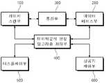
도 1을 참조하면, 항공기 주기유도 시스템은 레이저 스캔부(100), 데이터베이스부(200), 통신부(300) 및 데이터분석 판정 알고리즘 처리부(400)를 포함하도록 구성될 수 있다. 데이터분석 판정 알고리즘 처리부(400)는 알고리즘 처리부(400) 또는 데이터 처리부(400)로 지칭될 수도 있다. 또한, 항공기 주기유도 시스템은 디스플레이부(500) 및 항공기 제어부(600)를 더 포함하도록 구성될 수 있다.Referring to FIG. 1 , the aircraft main guidance system may be configured to include a
레이저 스캔부(100)는 항공기의 주기유도 및 주기 제어와 연관된 데이터를 획득하도록 구성될 수 있다. 데이터베이스부(200)는 레이저 스캔부(100)를 이용한 항공기 주기유도 및 주기 제어의 대상이 되는 항공기 기종별 규격 및 특징과 연관된 정보를 저장하도록 구성될 수 있다. 통신부(300)는 레이저 스캔부(100)와 데이터베이스부(200) 사이에서 정보를 송수신하도록 구성될 수 있다.The
데이터분석 판정 알고리즘 처리부(400)는 레이저 스캔부(100)를 통해 획득한 정보와 데이터베이스부(200)에 저장된 정보를 비교하도록 구성될 수 있다. 데이터분석 판정 알고리즘 처리부(400)는 획득한 영상정보와 저장된 정보를 비교하여 대상물의 정보를 판정하도록 구성될 수 있다. 디스플레이부(500)는 데이터분석 판정 알고리즘 처리부(400)에서 생성된 정보를 조종사 안내 표시기에 표시하도록 구성될 수 있다. 항공기 제어부(600)는 디스플레이부(500)에 송신된 정보를 기반으로 항공기 자동 제어가 가능하도록 구성될 수 있다.The data analysis determination
한편, 도 2는 본 발명에 따른 3차원 레이저 스캐너에 해당하는 레이저 스캔부(100)의 상세 구성을 나타낸 것이다. 도 2를 참조하면, 레이저 스캔부(100)는 레이저 송수신장치(110), 거리측정장치 (120)및 영상 데이터 스캔장치(130)를 포함하도록 구성될 수 있다.Meanwhile, FIG. 2 shows a detailed configuration of the
레이저 송수신장치(110)는 레이저를 송출하고 대상물에 의해 반사되는 레이저를 수신하도록 구성될 수 있다. 거리측정장치는 레이저 송수신장치(110)와 동작 가능하도록 결합될 수 있다. 거리측정장치는 레이저의 송신 시간 및 수신 시간으로부터 대상물까지의 거리 측정이 가능하도록 구성될 수 있다. 영상 데이터 스캔장치(130)는 레이저 송수신장치(110)와 동작 가능하도록 결합될 수 있다. 영상 데이터 스캔장치(130)는 항공기의 중심선, 항공기가 접현될 주기장을 스캔하여 영상 데이터를 생성하도록 구성될 수 있다. 영상 데이터 스캔장치(130)는 영상 카메라 장치로 구현될 수 있지만, 이에 한정되는 것은 아니다.The
이와 관련하여, 항공기 시각주기 유도 시스템의 유도 정보와 영상카메라의 영상 데이터의 동기화 방법에 대해 설명하면 아래와 같다.In this regard, a method of synchronizing guidance information of an aircraft visual cycle guidance system and image data of an image camera will be described below.
시각주기 유도 시스템은 영상 카메라를 포함하고 있으며, 영상 카메라는 주기장 영상을 촬영하여 실시간으로 운영자에게 제공하고 서버에 저장되며, 시각주기 유도 시스템의 유도 정보와 동기화하여 사고 발생이나 사고 이후 사고조사에도 활용된다.The visual cycle induction system includes a video camera, and the video camera captures an image of the apron and provides it to the operator in real time and is stored in the server. do.
시각주기 유도 시스템의 유도 정보는 중심 유도선과 정지 유도선을 기준으로 정확한 거리, 위치, 속도 등의 항공기 진입 정보를 갖고 있고, 이 정보는 항공기 진입부터 정지까지 공항 시간서버와 동기화된 시간정보와 함께 시스템에 저장된다. Guidance information of the visual cycle guidance system has aircraft entry information such as exact distance, location, and speed based on the center guidance line and the stop guidance line, and this information is synchronized with the airport time server from entry to stop. stored in the system.
영상카메라는 항공기 진입 여부와 상관없이 주기장을 녹화하여 서버에 저장하고 있고, 항공기 진입이 예정된 시간부터 항공기 진입이 완료되었을 때까지 별도로 녹화하여 시스템에 저장된다. 이 영상정보는 공항 시간서버와 동기화된 시간정보를 포함한다. The video camera records the apron regardless of whether the aircraft enters or not, and stores it in the server. This image information includes time information synchronized with the airport time server.
영상 정보는 진입하는 항공기의 상태를 직관적으로 쉽게 이해할 수 있으나, 정확한 거리, 위치, 속도를 판단하기가 어렵기에 시각주기 유도 시스템의 유도 정보와 동기화하여 진입했던 항공기 거리, 위치, 속도를 동시에 화면에 표출하여 직관적으로 이해할 수 있도록 한다. The image information makes it easy to intuitively understand the state of the incoming aircraft, but it is difficult to determine the exact distance, location, and speed. Express it so that it can be intuitively understood.
영상 데이터와 유도 정보는 동기화된 공항 시간서버의 시간을 동시에 갖고 있으며, 이를 활용하여 동기화한다.The video data and guidance information have the time of the synchronized airport time server at the same time and are synchronized using this.
동기화된 데이터의 재생 프로그램은 영상 데이터 또는 유도 정보를 선택하여 재생할 수 있고, 각각의 데이터는 읽혀진 시간정보를 활용하여 같은 시간대의 정보를 화면에 표출한다.The synchronized data reproduction program can select and reproduce image data or guidance information, and each data uses the read time information to display information in the same time zone on the screen.
공항 시간 서버의 시간이 제공 불가하다면 유도 정보의 시작 시점과 영상 데이터의 시작 시점을 기준으로 유도 정보는 단위 정보 단위로, 영상 데이터는 영상 키프레임 단위로 분석하여 동기 최적화를 진행한다.If the time of the airport time server is not available, synchronization optimization is performed by analyzing the guidance information in units of information units and the image data in units of image keyframes based on the start time of the guidance information and the start time of the image data.
한편, 본 발명에 따른 레이저 스캔부(100)는 오브젝트들의 특징적인 점군(point group)을 스캔하여, 데이터분석 판정 알고리즘 처리부(400)가 항공기로 판단된 오브젝트들을 항공기 프로파일과 비교할 수 있다. 이와 관련하여, 레이저 스캔부(100)는 3D 스캐너로 상기 항공기의 진입이 예상되는 영역 내에서 오브젝트들의 특징적인 점군(point group)을 스캔하도록 구성될 수 있다.Meanwhile, the
한편, 데이터분석 판정 알고리즘 처리부(400)는 스캔된 점군으로부터 상기 점군 간의 거리를 판단하여 오브젝트들을 생성하도록 구성될 수 있다. 데이터분석 판정 알고리즘 처리부(400)는 생성된 오브젝트들이 항공기로 예상되는 일정 크기 이상의 오브젝트로 판단되면, 항공기로 판단된 오브젝트들을 항공기 프로파일과 비교할 수 있다. 이와 관련하여, 항공기 프로파일은 항공기의 길이, 높이, 너비, 엔진간 거리, 엔진크기로 이루어진 항공기 제원에 관한 정보로 구성될 수 있다.Meanwhile, the data analysis determination
이와 관련하여, 항공기 시각주기 유도 시스템의 3차원 스캐너를 이용한 항공기 제원정보 구축 방법에 대해 설명하면 다음과 같다.In this regard, a method of constructing aircraft specification information using a three-dimensional scanner of an aircraft visual cycle guidance system will be described as follows.
시각주기 유도 시스템은 유도하는 항공기의 제원정보를 기준으로 프로파일 생성하고 생성된 프로파일과 진입하는 항공기의 3차원 데이터 정보를 비교하여 항공기 기종을 판단한 후 유도 중심선과 유도 정지선을 기준으로 항공기를 유도한다.The visual cycle guidance system generates a profile based on the specification information of the inducing aircraft, compares the generated profile with the three-dimensional data information of the incoming aircraft to determine the aircraft type, and then guides the aircraft based on the guidance center line and the guidance stop line.
항공기 프로파일은 항공기 제작사에서 제공되는 동체 크기, 엔진 크기, 날개 크기, 코의 높이, 코와 엔진사이 거리, 엔진과 엔진 사이 거리 등을 기준으로 생성된다. 이는 항공기 제작사의 자료 없이는 불가능하기 때문에 이러한 정보가 제공되지 않을 시 시각주기 유도 시스템의 3차원 스캐너를 이용하여 항공기 제원정보를 추출하는 방법이 사용된다.The aircraft profile is created based on the fuselage size, engine size, wing size, nose height, nose-engine distance, and engine-engine distance provided by the aircraft manufacturer. Since this is impossible without data from the aircraft manufacturer, when such information is not provided, a method of extracting aircraft specification information using a three-dimensional scanner of the visual cycle guidance system is used.
항공기 제원정보 구축을 실시하는 방법은 다음과 같다. 항공기가 주기장에 진입 후 완전히 정지할 때까지 대기한다. 항공기의 크기를 추산하기 어렵기 때문에 3차원 스캐너의 한계 각도와 거리까지 스캔을 시작하여, 항공기의 대략적인 크기를 추산한다. 항공기의 대략적인 크기를 추산하였다면 그 범위만 정밀 스캔하여 시스템이 항공기의 동체와 엔진, 날개 등의 특징을 찾도록 한다.The method of constructing aircraft specification information is as follows. Wait until the aircraft comes to a complete stop after entering the stand. Since it is difficult to estimate the size of the aircraft, the approximate size of the aircraft is estimated by starting the scan up to the limit angle and distance of the 3D scanner. If the approximate size of the aircraft is estimated, only the range is precisely scanned so that the system finds the characteristics of the aircraft's fuselage, engine, and wing.
항공기는 동체, 코, 엔진, 날개의 위치와 크기는 다르나 형체는 항상 비슷한 모양이 갖고 있기에 스캔된 데이터로 위치를 특정 할 수 있고 이를 활용해 항공기의 제원정보를 생성할 수 있다.The position and size of the body, nose, engine, and wing of an aircraft are different, but the shape is always the same, so the location can be specified with the scanned data, and the specification information of the aircraft can be created using this.
항공기를 정면에서 스캔했을 때, 항공기 코의 위치는 스캔된 위치에서부터 가장 가까운 거리에 있고, 엔진은 코를 중심으로 좌, 우측에 원형의 오브젝트 형태로 위치하고 있다. 이 원형의 오브젝트 중심과 코의 위치간 거리가 코와 엔진 사이의 거리가 되고, 좌, 우측에 있는 원형의 오브젝트 중심이 엔진간 거리가 된다.When the aircraft is scanned from the front, the position of the nose of the aircraft is the closest distance from the scanned position, and the engine is located in the form of a circular object on the left and right sides with the nose as the center. The distance between the center of the circular object and the position of the nose becomes the distance between the nose and the engine, and the center of the circular object on the left and right becomes the distance between the engines.
한편, 본 발명에 따른 데이터분석 판정 알고리즘 처리부(400)는 항공기의 해당 모델을 판단할 수 있다. 이와 관련하여, 데이터분석 판정 알고리즘 처리부(400)는 항공기가 진입 시 엔진으로 예측되는 오브젝트를 기준으로 엔진의 기울기를 판단할 수 있다. 또한, 데이터분석 판정 알고리즘 처리부(400)는 항공기의 코라고 예상되는 점을 기준으로 양쪽 엔진 위치에 형성된 점군의 개수를 확인하여 일정 수 이상이면, 항공기의 해당 모델을 판단할 수 있다.Meanwhile, the data analysis determination
한편, 본 발명에 따른 항공기 제어부(600)는 PDU (Pilot Display Unit)의 내부에 설치된 3축 센서를 이용하여 획득된 기울기 정보를 이용하여, 초기화 단계, 사용자 보정 단계 및 자동 보정단계를 수행할 수 있다. 이와 관련하여, 항공기의 레이저 스캔부(100)에서 스캔한 영상을 비교하는데 있어서, PDU의 3축을 보정하는 것은 (Pitch, Roll, Yaw를 측정할 수 있는) 3축 센서이다. 한편, 3축 센서는 PDU의 내부에 설치되어 있고, 직렬(Serial)통신으로 메인 PC와 통신에 따라 데이터를 주고받을 수 있는 상태로 구성될 수 있다.On the other hand, the
이와 관련하여, 항공기 시각주기 유도 시스템의 3축 센서를 이용한 변위 발생 감지 및 보정 방법에 대해 설명하면 다음과 같다.In this regard, a method for detecting and correcting displacement using a three-axis sensor of an aircraft visual cycle induction system will be described as follows.
시각주기 유도 시스템은 3축 센서(Picth, Roll, Yaw)를 포함하고 있으며, 3축 센서는 함체의 변위를 일정시간마다 측정하여 초기 설정된 위치정보와 비교함으로써 함체의 변위를 감시하고, 자동 또는 수동으로 이를 보정한다.The visual cycle induction system includes 3-axis sensors (Picth, Roll, Yaw), and the 3-axis sensor monitors the displacement of the enclosure by measuring the displacement at regular intervals and comparing it with the initially set position information, and automatically or manually correct this with
시각주기 유도 시스템의 초기 설치 시 함체가 벽면 또는 폴(기둥)에 고정이 완료되었다면 3축 센서의 3축 정보(Picth, Roll, Yaw)를 시스템에 저장하고, 이 값을 초기값으로 설정한다. 시스템은 일정시간마다 현재 3축 센서에서 3축 정보를 취득하고, 이 값을 초기값과 비교하여 변위 발생을 감지한다. 이 때 허용오차를 두어 센서의 오차와 변위 허용 오차를 감안한다.When the visual cycle induction system is initially installed, if the housing is fixed to the wall or pole (pillar), the 3-axis information (Picth, Roll, Yaw) of the 3-axis sensor is stored in the system, and this value is set as the initial value. The system acquires 3-axis information from the current 3-axis sensor at regular intervals and compares this value with an initial value to detect displacement. At this time, the error of the sensor and the tolerance of the displacement are taken into account by setting the tolerance.
허용 오차를 넘는 변위 차이가 측정되었다면 시스템은 이 변위 오차를 스캐너의 3축 보정수치에 적용하여 초기 설치 때 설정한 스캐너의 3축 정보를 변경한다. 스캐너의 3축 정보는 함체에 상대적인 스캐너의 3축 정보이다If a displacement difference exceeding the allowable error is measured, the system applies this displacement error to the 3-axis correction value of the scanner to change the 3-axis information of the scanner set at the time of initial installation. The three-axis information of the scanner is the three-axis information of the scanner relative to the enclosure.
변위차가 발생했음에도 안정상의 이유로 자동으로 스캐너 3축을 보정하지 않거나, 보정 허용 오차 이상으로 변위가 발생했을 경우에는 운영자가 수동으로 이를 다시 보정해줘야 한다. 이는 초기 설치와 같은 스캐너, 함체 3축 캘리브레이션을 진행해야 한다.Even if there is a displacement difference, if the 3 axes of the scanner are not automatically calibrated for stability reasons, or if the displacement exceeds the calibration tolerance, the operator must manually re-calibrate it. This requires the same scanner and enclosure 3-axis calibration as the initial installation.
한편, 3차원 레이저 스캐너의 제어방법은 2차원 레이저 스캐너와 스텝 모터를 사용하여 구현할 수도 있다. 이와 관련하여, 2차원 레이저 스캐너와 스텝 모터를 사용한 3차원 레이저 스캐너의 제어방법에 대해 설명하면 다음과 같다.Meanwhile, the control method of the 3D laser scanner may be implemented using a 2D laser scanner and a stepper motor. In this regard, a 2D laser scanner and a method of controlling a 3D laser scanner using a step motor will be described as follows.
2차원 레이저 스캐너와 스텝 모터를 기구적으로 결합하여 3차원 레이저 스캐너를 제작할 수 있다. 기구는 2차원 레이저 스캐너의 레이저 광원 원점을 기준으로 스텝 모터의 회전부와 결합하여 스텝 모터의 회전 시 2차원 레이저가 상하로 이동하여 3차원 스캔이 가능하도록 한다.A 3D laser scanner can be manufactured by mechanically combining a 2D laser scanner and a stepper motor. The mechanism is combined with the rotating part of the step motor based on the origin of the laser light source of the 2D laser scanner, and the 2D laser moves up and down when the stepper motor rotates to enable 3D scanning.
3차원 데이터를 추출하기 위해선 스텝 모터의 각도, 레이저 스캐너의 포인트별 거리, 각도를 각 장치로부터 통신으로 획득하여 3차원 데이터로 변환한다. 각 장치의 정보를 통신으로 얻어오게 되면 각 장치의 통신속도 및 통신지연 현상으로 인해 오차가 발생하기에 오차를 제거하기 위해 각 장차의 RTC를 활용하여 동기화할 수 있다.In order to extract 3D data, the angle of the step motor, the distance and the angle of each point of the laser scanner are obtained through communication from each device and converted into 3D data. When the information of each device is obtained through communication, an error occurs due to the communication speed and communication delay of each device. In order to eliminate the error, it can be synchronized by utilizing the RTC of each future.
완벽한 RTC 동기화에도 정보를 취득하는 시점이 다르므로 기준은 스캐너의 RTC로하며, 스텝 모터 정보는 일정시간 이후에 도착하므로 모터의 이동 속도와 스캐너 모터의 RTC 차이로 스캐너 정보 획득 시간에 모터 각도를 예측한다.Even with perfect RTC synchronization, the time at which information is acquired is different, so the standard is the RTC of the scanner, and the step motor information arrives after a certain time, so the motor angle is predicted at the scanner information acquisition time by the difference between the moving speed of the motor and the RTC of the scanner motor do.
2차원 스캔 데이터는 모터 각도에 따라 3차원 좌표의 대각선 거리이고, 이 3차원 대각선 거리, 스캔 각도, 모터 각도를 각 좌표의 계산식에 따라 스캐너를 기준으로 하는 3차원 절대 좌표를 산출한다.The two-dimensional scan data is the diagonal distance of the three-dimensional coordinates according to the motor angle, and the three-dimensional absolute coordinates based on the scanner are calculated according to the formula for calculating the three-dimensional diagonal distance, the scan angle, and the motor angle.
3차원 좌표 계산 프로세스는 2차원 스캐너와, 모터의 정보를 지속적으로 요청하여 수집하고, 계산하여 3차원 데이터를 실시간 생성한다. 상위 프로세스는 필요에 따라 3차원 좌표 계산 프로세스에 현재 3차원 데이터를 요청하고, 3차원 좌표 계산 프로세스는 상위 프로세스의 요청에 대응한다.The three-dimensional coordinate calculation process continuously requests, collects, and calculates the information of the two-dimensional scanner and the motor to generate three-dimensional data in real time. The upper process requests the current three-dimensional data to the three-dimensional coordinate calculation process as necessary, and the three-dimensional coordinate calculation process responds to the request of the upper process.
3축 센서의 3차원 데이터와 관련하여, 항공기 제어부(600)는 PDU (Pilot Display Unit)의 내부에 설치된 3축 센서를 이용하여 각 축에 해당하는 Pitch, Roll, Yaw 기울기 정보를 획득하도록 구성될 수 있다. 항공기 제어부(600)는 획득된 기울기 정보를 초기값으로 상기 데이터베이스부(200)에 저장하는 초기화 단계를 수행하도록 구성될 수 있다.With respect to the three-dimensional data of the three-axis sensor, the
항공기 제어부(600)는 PDU의 3축 센서를 이용하여 상기 각 축의 기울기 정보를 획득하여 획득된 기울기 정보를 초기값과 비교하여 허용치를 벗어나는지 여부를 판단하도록 구성될 수 있다. 초기값과 비교하여 허용치를 벗어나면, 항공기 제어부(600)는 PDU를 통해 사용자에게 통보하고, 메인터턴스툴(MTT)을 이용하여 3D 스캐너의 3축을 보정하는 사용자 보정 단계를 수행할 수 있다.The
초기값과 비교하여 허용치를 벗어나면, 항공기 제어부(600)는 자동 보정단계를 수행할 수 있다. 이와 관련하여, 항공기 제어부(600)는 PDU의 3축 센서를 이용하여 상기 각 축의 기울기 정보를 획득하여 획득된 기울기 정보를 초기값과 비교하여 허용치를 벗어나는지 여부를 판단하도록 구성될 수 있다. 초기값과 비교하여 허용치를 벗어나면, 항공기 제어부(600)는 자동으로 3D 스캐너의 3축 기울기 값을 보정하고, 보정된 값을 초기값으로 저장하는 자동 보정단계를 수행할 수 있다.If it is out of the allowable value compared to the initial value, the
한편, 본 발명에 따른 항공기 제어부(600)는 항공기를 유도하기 위한 중심선을 설정하도록 구성될 수 있다. 이를 위해, 항공기 제어부(600)는 항공기가 접현될 주기장에 스캔 가능한 물체의 3점을 중심선으로부터 시작점과 끝점에 배치하고, 3D 스캐너로 상기 주기장을 스캔하도로 구성될 수 있다. 항공기 제어부(600)는 스캔된 데이터로 생성된 화면에서 중심선의 시작점 물체를 클릭하도록 표시하고, 화면에서 물체를 클릭하면 클릭된 물체를 중심선의 FP(First Point)로 지정할 수 있다.On the other hand, the
또한, 항공기 제어부(600)는 스캔된 데이터로 생성된 화면에서 중심선의 끝점 물체를 클릭하도록 표시하고, 화면에서 물체를 클릭하고 클릭된 물체를 중심선으로 SP(Second Point)로 지정할 수 있다. 이에 따라, 항공기 제어부(600)는 FP와 SP를 이용하여 항공기를 유도하기 위한 중심선을 설정하도록 구성될 수 있다.In addition, the
한편, 본 발명에 따른 항공기 주기유도 시스템은 PDU (Pilot Display Unit)의 초기 설치 시 설치 초기값과 이후 측정 값의 차이에 따라 PDU의 3축 기울기 값을 보정할 수 있다. 이와 관련하여, 항공기 제어부(600)는 PDU (Pilot Display Unit)의 초기 설치 시 3축 센서를 이용하여 설치 초기값을 저장하고, 일정 시간마다 초기값과 측정값을 비교하도록 구성될 수 있다. 항공기 제어부(600)는 초기값과 측정값의 차이가 허용치를 넘는 경우, 상기 PDU 및 MCB를 통해 상기 허용치를 넘는 것으로 통보할 수 있다. 항공기 제어부(600)는 초기값과 측정값의 차이가 허용치를 넘지 않도록 PDU의 3축 기울기 값을 보정하도록 구성될 수 있다.On the other hand, the aircraft main guidance system according to the present invention may correct the 3-axis inclination value of the PDU according to the difference between the initial installation value and the subsequent measurement value when the PDU (Pilot Display Unit) is initially installed. In this regard, the
한편, 본 발명에 따른 항공기 주기유도 시스템은 항공기를 정지 유도 시 시간차로 인한 정지 오차를 학습하도록 구현될 수 있다. 이를 위해, 항항공기 제어부(600)는 항공기를 정지 유도 시 현시되는 정지 사인을 인지하고 정지 할 때까지의 시간차로 인한 정지 오차를 빅 데이터로 학습하도록 구성될 수 있다.On the other hand, the aircraft main guidance system according to the present invention can be implemented to learn a stop error due to a time difference when inducing the aircraft to stop. To this end, the
이와 관련하여, 운영시스템 서버의 조종사현시장치 제어 방법에 대해 설명하면 다음과 같다.In this regard, a method for controlling the pilot display device of the operating system server will be described as follows.
운영시스템 서버는 상위 연계 공항 시스템으로부터 항공편별 고유의 식별자를 가지는 지상항공이동정보를 수신하고 지상항공이동정보의 도착시간을 사용하여 가장 가까운 시간의 항공기를 우선하여 계류장의 조종사현시장치를 원격으로 제어한다.The operating system server receives the ground air movement information with a unique identifier for each flight from the upper linked airport system, and uses the arrival time of the ground air movement information to give priority to the closest aircraft to remotely control the pilot display at the apron. do.
이와 관련하여, 운영시스템 서버의 조종사현시장치 제어 방법에서의 시퀀스 관리 방법에 대해 설명하면 다음과 같다.In this regard, a sequence management method in the pilot display device control method of the operating system server will be described as follows.
운영시스템 서버의 조종사 현시장치 제어 방법에 이어, 지상항공이동정보의 식별자, 출발 및 도착 시간의 오류 데이터 검사, 출발 시간이 현재 시간을 지났을 경우를 판단하여 제어 시퀀스가 생성된다. 생성된 시퀀스는 차량으로 견인되는 항공기와 조종사가 주기하는 항공기를 구분하고 판단하여 조종사현시장치의 시각유도정보의 제공 여부를 결정한다. 조종사현시장치의 기 동작 여부를 판단하고 다중 조종사현시장치가 설치된 하나의 계류장의 인접 중심유도선 간의 충돌을 방지하며 사용자가 정한 시간 이전에 조종사현시장치를 활성화하여 조업자와 조종사에게 안전하고 원활한 접현정보 및 유도정보를 제공한다. 이러한 과정을 거쳐 수행된 제어 시퀀스의 지상항공이동정보 식별자, 항공기 기종, 활성화 시간을 운영시스템 서버에 파일로 기록하여 관리한다.Following the pilot display device control method of the operating system server, an identifier of ground air movement information, error data inspection of departure and arrival times, and a case in which the departure time has passed the current time are determined to generate a control sequence. The generated sequence distinguishes an aircraft towed by a vehicle and an aircraft parked by a pilot and determines whether to provide visual guidance information of the pilot display device. It judges whether the pilot display device is in operation, prevents collision between adjacent center taxi lines at one apron where multiple pilot display devices are installed, and activates the pilot display device before the user-specified time to ensure safe and smooth landing for operators and pilots. Provides information and guidance information. The ground air movement information identifier, aircraft type, and activation time of the control sequence performed through this process are recorded and managed as a file in the operating system server.
한편, 제어 시퀀스의 변경에 따른 조종사현시장치의 제어 방법에 대해 설명하면 다음과 같다.On the other hand, the control method of the pilot display device according to the change of the control sequence will be described as follows.
시스템은 상위 연계 공항 시스템으로부터 실시간으로 발생하는 지상항공이동정보와 시스템에 기록된 파일을 비교하여 지상항공이동정보 식별자의 주요 정보의 변경을 포착하여 조종사현시장치의 제어를 판단하고 다음을 수행한다. 지상항공이동정보의 변경으로 조종사현시장치 간 계류장이 변경되었을 때 조종사현시장치를 제어하여 계류장의 변경을 제어한다. 지상항공이동정보의 변경으로 도착시간을 판단하여 도착시간이 변경되었을 때 조종사현시장치의 동작시간을 제어한다. 지상항공이동정보의 변경으로 항공기의 기종이 변경되었을 때 조종사현시장치의 항공기 기종을 변경한다.The system compares the ground air movement information generated in real time from the upper linked airport system with the file recorded in the system, catches changes in the main information of the ground air movement information identifier, determines the control of the pilot display device, and performs the following. When the apron between pilot display devices is changed due to the change of ground air movement information, the change of the apron is controlled by controlling the pilot display device. It determines the arrival time by changing the ground air movement information and controls the operation time of the pilot display device when the arrival time is changed. When the aircraft type is changed due to the change of ground air movement information, the aircraft type of the pilot display device is changed.
한편, 제어 시퀀스의 수동 입력 방법에 대해 설명하면 다음과 같다. 모든 제어 시퀀스는 운영시스템 관제프로그램에서 모든 정보를 사용자가 입력할 수 있다.Meanwhile, a manual input method of the control sequence will be described as follows. For all control sequences, the user can input all information in the operating system control program.
한편, 다른 타입의 데이터에 대한 학습을 통해 항공기를 정지 유도 시 현시되는 정지 사인의 표시 시점을 자동으로 조정할 수 있다.On the other hand, it is possible to automatically adjust the display timing of the stop sign displayed when the aircraft is guided to stop by learning from other types of data.
이와 관련하여, 항공기 제어부(600)는 항공기를 정지 유도 시 정지 사인을 표시하는 거리, 상기 항공기가 정지한 거리, 정지 오차, 항공기 기종을 포함하는 제1 타입 데이터를 저장하도록 제어할 수 있다. 항공기 제어부(600)는 비, 눈, 안개와 연관된 날씨, PDU 설치 높이, 각도를 포함하는 환경적 요인과 연관된 제2 타입 데이터를 저장하도록 제어할 수 있다. 항공기 제어부(600)는 제1 타입 데이터 및 제2 타입 데이터를 항공기종, 정지거리, 환경적 요인을 각 변수로 통계화 및 학습을 수행할 수 있다. 따라서, 항공기 제어부(600)는 학습된 제1 타입 데이터 및 제2 타입 데이터를 이용하여 항공기를 정지 유도 시 현시되는 정지 사인의 표시 시점을 자동으로 조정하도록 구성될 수 있다.In this regard, the
이상에서는 본 발명의 일 양상에 따른 본 발명에 따른 3차원 레이저 스캐너를 이용한 항공기 주기유도 시스템에 대해 설명하였다. 이하에서는, 본 발명의 다른 양상에 따른 3차원 레이저 스캐너를 이용한 항공기 주기유도 시스템을 이용한 항공기 주기 제어방법에 대해 설명한다.In the above, an aircraft main guidance system using a three-dimensional laser scanner according to the present invention according to an aspect of the present invention has been described. Hereinafter, an aircraft period control method using an aircraft period guidance system using a three-dimensional laser scanner according to another aspect of the present invention will be described.
먼저, 레이저 스캔부(100)의 항공기 및 항공기 모델 식별 방법은 다음과 같이 구성될 수 있다. 이와 관련하여, 도 3은 본 발명의 실시 예에 따른, 본 발명에 따른 항공기 주기 제어방법에서 항공기 및 항공기 모델 식별 방법의 흐름도이다. 도 3을 참조하면, 항공기 및 항공기 모델 식별 방법은 이하의 제1단계 (S110) 내지 제4단계 (S140)를 포함하도록 구성될 수 있다.First, the method of identifying the aircraft and the aircraft model of the
제1단계 (S110) - 3D 스캐너로 항공기의 진입이 예상되는 영역을 스캔한다.Step 1 (S110) - A 3D scanner scans the area where the aircraft is expected to enter.
제2단계 (S120) - 스캔된 점군간 거리를 판단하여 오브젝트를 생성한다.Step 2 (S120) - An object is created by determining the distance between the scanned point clouds.
제3단계 (S130) - (항공기로 예상되는) 일정크기 이상의 오브젝트가 있을시 항공기로 판단한다.Third step (S130) - When there is an object of a certain size or larger (expected to be an aircraft), it is determined as an aircraft.
제4단계 (S140) - 항공기라 판단된 오브젝트들을 항공기 프로파일과 비교한다. 여기서, 항공기 프로파일은 항공기의 길이, 높이, 너비, 엔진간 거리, 엔진크기 등으로 이루어진 항공기 제원에 관한 정보이다.Step 4 (S140) - The objects determined to be aircraft are compared with the aircraft profile. Here, the aircraft profile is information on aircraft specifications including the length, height, width, distance between engines, and engine size of the aircraft.
다음으로, 레이저 스캔부(100)에서 스캔한 영상을 비교하는 방법은 다음과 같이 구성될 수 있다. 이와 관련하여, 도 4는 본 발명의 실시 예에 따른 항공기 주기 제어방법과 관련하여 스캔한 영상을 비교하는 방법의 흐름도이다. 도 4를 참조하면, 스캔한 영상을 비교하는 방법은 이하의 제1단계 (S210) 및 제2단계 (S220)를 포함하도록 구성될 수 있다.Next, a method of comparing images scanned by the
제1단계 (S210) - 항공기가 진입시 정면이 아니기 때문에 엔진으로 예측되는 오브젝트를 기준으로 기울기를 판단한다.Step 1 (S210) - Since the aircraft is not in front when entering, the inclination is determined based on the object predicted by the engine.
제1단계 (S220) - 항공기 코라고 예상되는 점을 기준으로 양쪽 엔진 위치에 형성된 점군의 개수를 확인하여 일정 수 이상이면 해당 모델이라고 판단한다.Step 1 (S220) - The number of point groups formed at both engine positions is checked based on the point expected to be the nose of the aircraft, and if the number is greater than a certain number, it is determined that the model is the corresponding model.
또한, 항공기의 스캔부에서 스캔한 영상을 비교하는데 있어서, Pilot Display Unit의 3축을 보정하는 것은 (Pitch, Roll, Yaw를 측정할 수 있는) 3축 센서가 PDU(Pilot Display Unit)의 내부에 설치되도록 구성된다. 한편, PDU 내부에 설치된 3축 센서는 직렬(Serial) 통신으로 메인 PC와 통신으로 데이터를 주고받을 수 있는 상태로 구성된다. 이에 따라, 3축 센서를 통해 아래와 같이 초기화 단계, 사용자 보정단계, 자동보정단계를 수행할 수 있다. 이와 관련하여, 초기화 단계를 수행한 이후 사용자 보정단계, 자동보정단계 중 적어도 하나를 수행할 수 있다. 이와 관련하여, 도 5는 실시 예에 따른 3축 데이터 초기화 및 보정 방법의 흐름도이다. 도 5는 초기화 단계(S310), 사용자 보정단계(S320), 자동보정단계(S330)가 순차적으로 표시되었지만, 사용자 보정단계(S320) 및 자동보정단계(S330)가 순서에 한정되는 것은 아니다.In addition, in comparing the images scanned by the scan unit of the aircraft, to calibrate the 3 axes of the pilot display unit, a 3-axis sensor (which can measure pitch, roll, and yaw) is installed inside the PDU (Pilot Display Unit). configured to be On the other hand, the 3-axis sensor installed inside the PDU is configured in a state in which data can be exchanged with the main PC through serial communication. Accordingly, the initialization step, the user calibration step, and the automatic calibration step can be performed through the 3-axis sensor as follows. In this regard, after performing the initialization step, at least one of a user calibration step and an automatic calibration step may be performed. In this regard, FIG. 5 is a flowchart of a method for initializing and correcting 3-axis data according to an embodiment. Although the initialization step (S310), the user calibration step (S320), and the automatic calibration step (S330) are sequentially displayed in FIG. 5, the user calibration step (S320) and the automatic calibration step (S330) are not limited to the order.
초기화 단계(S310)는 제1단계 (S311) 및 제2단계 (S312)를 포함하도록 구성될 수 있다.The initialization step ( S310 ) may be configured to include a first step ( S311 ) and a second step ( S312 ).
제1단계 (S311) - 설치되어 있는 PDU의 3축센서의 각축(Pitch, Roll, Yaw) 기울기 정보를 획득하고,Step 1 (S311) - Acquire the inclination information of each axis (Pitch, Roll, Yaw) of the 3-axis sensor of the installed PDU,
제2단계 (S312) - 획득된 정보를 초기값으로 저장하여 보관한다.Second step (S312) - The obtained information is stored as an initial value and stored.
사용자 보정단계(S320)는 제1단계 (S321) 내지 제4단계 (S324)를 포함하도록 구성될 수 있다.The user calibration step (S320) may be configured to include the first step (S321) to the fourth step (S324).
제1단계 (S321) - 설치되어 있는 PDU의 3축 센서의 각축(Pitch, Roll, Yaw)의 기울기 정보를 획득한다.Step 1 (S321) - Acquire information on the inclination of each axis (Pitch, Roll, Yaw) of the 3-axis sensor of the installed PDU.
제2단계 (S322) - 초기값과 비교하여 허용치에서 벗어난 경우 사용자에게 알린다.Step 2 (S322) - If it is out of the allowable value compared to the initial value, the user is notified.
제3단계 (S323) - 사용자로 하여금 메인터넌스툴(MTT)을 이용하여 3D스캐너의 3축을 보정하도록 한다.3rd step (S323) - Let the user calibrate the 3 axes of the 3D scanner using a maintenance tool (MTT).
이와 관련하여, 3축 센서의 각 축, 즉 Pitch, Roll, Yaw의 3축 별로 초기값과 측정값을 비교하여 허용치 범위를 벗어났는지 여부를 판단할 수 있다. 이와 관련하여, 표 1은 3축 별로 초기값, 측정값 및 허용치의 예시를 나타낸다.In this regard, by comparing the initial value and the measured value for each axis of the three-axis sensor, that is, for each of the three axes of Pitch, Roll, and Yaw, it can be determined whether or not it is outside the allowable range. In this regard, Table 1 shows examples of initial values, measured values, and allowable values for each of the three axes.
표 1을 참조하면, Pitch와 Roll값이 허용치를 넘었기 때문에 해당되는 3D 스캐너의 축을 보정한다. PDU는 3D스캐너에서 수집된 raw데이터에 보정값을 적용하여 계산한다.Referring to Table 1, the axes of the corresponding 3D scanner are calibrated because the pitch and roll values exceed the allowable values. PDU is calculated by applying the correction value to the raw data collected from the 3D scanner.
제4단계 (S324) - 보정된 값을 초기값으로 저장한다.Fourth step (S324) - The corrected value is stored as an initial value.
자동보정단계(S330)는 제1단계 (S331) 내지 제3단계 (S323)를 포함하도록 구성될 수 있다.The automatic correction step (S330) may be configured to include the first step (S331) to the third step (S323).
제1단계 (S331) - 설치되어 있는 PDU의 3축 센서의 각축(Pitch, Roll, Yaw) 기울기 정보를 획득한다.Step 1 (S331) - Acquire information on the inclination of each axis (Pitch, Roll, Yaw) of the 3-axis sensor of the installed PDU.
제2단계 (S332) - 초기값과 비교하여 허용치를 벗어난 경우 PDU가 자동으로 3D스캐너를 보정한다.Step 2 (S332) - The PDU automatically calibrates the 3D scanner if it is out of the allowable value compared to the initial value.
제3단계 (S332) - 보정된 값을 초기값으로 저장한다.Third step (S332) - The corrected value is stored as an initial value.
이와 관련하여, 도 1을 참조하면, 데이터베이스부(200)는 항공기 규격 및 특징이 저장되며, 새로운 기종에 대하여 추가적으로 저장되도록 구성될 수 있다. 한편, 통신부(300)는 레이저 스캔부(100)에서 수신된 데이터를 데이터베이스부(200)로 송수신 하도록 송수신장치를 포함하도록 구성될 수 있다. 데이터분석 판정 알고리즘 처리부(400)는 레이저 스캔부(100)를 통해 획득한 영상정보와, 상기 데이터베이스부(200)에 정보의 항공기 규격 및 특징을 비교하도록 하는 분석 알고리즘을 포함하도록 구성될 수 있다.In this regard, referring to FIG. 1 , the
디스플레이부(500)는 데이터분석 판정 알고리즘 처리부(400)에서 분석된 데이터를 시각화하기 위해 조종사 안내 표시기를 포함하도록 구성될 수 있다.The
항공기 제어부(600)는 디스플레이부(500)에 시각화된 데이터를 기반으로 항공기 주기유도를 위한 중앙제어, 원격제어, 자동제어 장치를 포함하도록 구성될 수 있다.The
한편, 본 발명에 따른 3차원 레이저 스캐너를 이용한 항공기 주기유도 시스템을 이용한 항공기 주기 제어방법에서, 항공기 제어부(600)는 항공기를 유도하기 위한 중심선을 설정한다.On the other hand, in the aircraft period control method using the aircraft period guidance system using the three-dimensional laser scanner according to the present invention, the
이와 관련하여, 주기장에 항공기를 접현시키기 위해서는 기준이 되는 선이 필요한데, 이 선을 중심선으로 명명한다. 한편, 도 6은 항공기 제어부(600)가 항공기 주기유도를 위한 중앙제어, 원격제어, 자동제어를 구현하기 위해서 중심선을 설정하는 방법의 흐름도이다. 도 6을 참조하면, 항공기 주기유도를 위한 중앙제어, 원격제어, 자동제어를 구현하기 위해서 중심선을 설정하는 방법은 제1단계 (S410) 내지 제7단계 (S470)를 포함하도록 구성될 수 있다.In this regard, a standard line is required to berth the aircraft at the apron, and this line is called the center line. Meanwhile, FIG. 6 is a flowchart of a method for the
제1단계 (S410) - 항공기가 접현될 주기장에 스캔 가능한 물체 3점을 중심선으로 시작점과 끝점에 배치한다.Step 1 (S410) - 3 scannable objects are arranged at the start and end points as the center line on the stand where the aircraft is to be docked.
제2단계 (S420) - 3D 스캐너로 주기장을 스캔한다.Step 2 (S420) - Scan the parking lot with a 3D scanner.
제3단계 (S430) - 스캔된 데이터로 그려진 화면에서 육안으로 중심선의 시작점 물체를 탐색한다.Step 3 (S430) - Search for the starting point object of the center line with the naked eye on the screen drawn with the scanned data.
제4단계 (S430) - 화면에서 물체를 클릭하고 이를 중심선의 FP(First Point)라 지정한다.Step 4 (S430) - Click the object on the screen and designate it as the FP (First Point) of the center line.
제5단계 (S450) - 스캔된 데이터로 그려진 화면에서 육안으로 중심선의 끝점 물체를 탐색한다.Step 5 (S450) - Search for the object at the end point of the center line with the naked eye on the screen drawn with the scanned data.
제6단계 (S460) - 화면에서 물체를 클릭하고 이를 중심선으로 SP(Second Point)라 지정한다.Step 6 (S460) - Click an object on the screen and designate it as SP (Second Point) as a center line.
제7단계 (S470) - FP와 SP를 이용하여 중심선을 설정한다.Step 7 (S470) - A center line is set using FP and SP.
한편, 본 발명에 따른 3차원 레이저 스캐너를 이용한 항공기 주기유도 시스템을 이용한 항공기 주기 제어방법에서, PDU 함체의 물리적인 뒤틀림을 확인하는 방법 및 보정하는 방법이 구현될 수 있다. 이와 관련하여, 도 7은 PDU 함체의 물리적인 뒤틀림을 확인하여 보정하는 방법의 흐름도이다. 도 7을 참조하면, 항공기 주기유도를 위한 중앙제어, 원격제어, 자동제어를 구현하기 위해서 중심선을 설정하는 방법은 제1단계 (S510) 내지 제4단계 (S540)를 포함하도록 구성될 수 있다. 구체적으로, 수직축(요), 가로축(피치), 세로축(롤)을 측정할 수 있는 센서를 이용한 PDU 함체의 물리적인 뒤틀림을 확인하는 방법 및 보정하는 방법은 제1단계 (S510) 내지 제4단계 (S540)를 포함하도록 구성될 수 있다.On the other hand, in the aircraft period control method using the aircraft period guidance system using the three-dimensional laser scanner according to the present invention, a method for checking and correcting the physical distortion of the PDU enclosure may be implemented. In this regard, FIG. 7 is a flowchart of a method of checking and correcting the physical distortion of the PDU enclosure. Referring to FIG. 7 , a method of setting a center line to implement central control, remote control, and automatic control for aircraft main guidance may be configured to include the first step (S510) to the fourth step (S540). Specifically, the method for checking and correcting the physical distortion of the PDU enclosure using a sensor capable of measuring the vertical axis (yaw), the horizontal axis (pitch), and the vertical axis (roll) is the first step (S510) to the fourth step. (S540) may be configured to include.
제1단계 (S510) - PDU 함체 내부 중앙에 3축 센서를 설치하고, 3축 센서의 구동을 위한 동작 여부를 확인한다.Step 1 (S510) - Install a 3-axis sensor in the center of the PDU housing, and check whether the 3-axis sensor operates for driving.
제2단계 (S520) - PDU 초기 설치 시 3축 센서를 측정하여 설치 초기값을 저장, 일정 시간 마다 초기값과 측정값을 비교한다.Step 2 (S520) - When the PDU is initially installed, the 3-axis sensor is measured, the installation initial value is stored, and the initial value and the measured value are compared at regular intervals.
제3단계 (S530) - 초기값과 측정값의 차이를 계산하여 설정된 허용치를 넘었는지 여부를 판단하여, 화면에 표시한다. 따라서, 설정된 허용치를 넘은 경우 PDU, MCB (Miniature Circuit breaker), 수동제어반 (Manual control panel) 및 운영시스템 등에 표시하여 사용자가 이를 확인할 수 있도록 한다.Step 3 (S530) - The difference between the initial value and the measured value is calculated to determine whether or not the set allowable value is exceeded, and displayed on the screen. Therefore, if the set allowable value is exceeded, it is displayed on the PDU, MCB (Miniature Circuit breaker), manual control panel, and operating system so that the user can check it.
제4단계 (S540) - 사용자는 측정값을 참고하여 PDU의 3축을 보정, PDU의 정확도 및 신뢰성을 유지한다. 이와 관련하여, 측정값에 따라 PDU의 3축을 보정할 수 있다.Step 4 (S540) - The user maintains the accuracy and reliability of the PDU by correcting the three axes of the PDU by referring to the measured value. In this regard, it is possible to correct the three axes of the PDU according to the measured value.
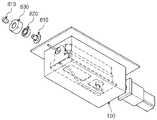
한편, 본 발명에 따른 항공기 주기유도 시스템을 이용한 항공기 주기 제어방법에서, 회전하는 부품(SCANNER)에 조립되어 있는 CABLE이 회전동작 중에도 손상되지 않으며 물의 침투를 방지하는 방법은 다음과 같이 구성될 수 있다. 이와 관련하여, 도 8a 및 도 8b는 본 발명에 따른 스캐너 구성의 조립도 및 단면도를 나타낸다. 스캐너는 3D 스캐너로 구성될 수 있고, 이를 위해 레이저 스캔부(100)로 구성될 수 있지만, 이에 한정되는 것은 아니다.On the other hand, in the aircraft period control method using the aircraft main guidance system according to the present invention, the cable assembled to the rotating part (SCANNER) is not damaged even during the rotation operation, and the method of preventing the penetration of water can be configured as follows. . In this regard, FIGS. 8A and 8B show an assembly view and a cross-sectional view of a scanner configuration according to the present invention. The scanner may be configured as a 3D scanner, and may be configured as a
도 8a 및 도 8b를 참조하면, 스캐너(100)가 내부에 배치되는 외함(150)의 일 측에 관통 홀이 형성되고, 관통 홀을 통해 케이블(160)이 배치될 수 있다. 외함(150)의 일 측에 형성된 관통 홀의 주변 영역에 샤프트(810), 베어링(820) 및 베어링 홀더(830)가 고정되게 배치될 수 있다. 방수용 케이블 gland(840)가 케이블(160)과 샤프트(810) 사이의 공간을 밀봉하도록 구성될 수 있다.Referring to FIGS. 8A and 8B , a through hole may be formed on one side of the
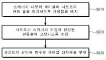
한편, 도 9는 본 발명에 따른 항공기 주기 제어방법과 관련하여, 케이블 손상 방지를 위한 스캐너 조립 방법의 흐름도를 나타낸다. 도 9를 참조하면, 스캐너 조립 방법은 제1단계(S610) 내지 제3단계(S630)를 포함하도록 구성될 수 있다.Meanwhile, FIG. 9 shows a flowchart of a method for assembling a scanner for preventing cable damage in relation to the method for controlling aircraft cycle according to the present invention. Referring to FIG. 9 , the scanner assembly method may be configured to include a first step ( S610 ) to a third step ( S630 ).
제1단계 (S610) - 회전하는 부품(SCANNER)에 조립되어 있는 CABLE이 회전동작 중에도 손상되지 않도록 SHAFT의 관통 HOLE 내부로 조립되도록 한다. 즉, 제1단계 (S610)는 스캐너의 내부의 케이블이 샤프트의 관통 홀을 통과하도록 케이블을 배치하는 단계이다. 이와 관련하여, 케이블이 배치 및 조립 시 케이블의 회전에 따른 길이 변화를 감안하여 일정 길이만큼 자유도를 확보한다.Step 1 (S610) - Make sure that the cable assembled in the rotating part (SCANNER) is assembled into the through hole of the shaft so that it is not damaged even during the rotating operation. That is, the first step ( S610 ) is a step of arranging the cable so that the cable inside the scanner passes through the through hole of the shaft. In this regard, when the cable is arranged and assembled, a degree of freedom is secured by a certain length in consideration of the length change due to the rotation of the cable.
제2단계 (S620) - 스캐너의 외함의 임의부분에 HOLE을 ?어서 CABLE을 조립할 경우, 1) CABLE의 운동범위를 구속시키기 어려우며, 2) 회전하는 부품이 회전 운동시 CABLE이 반복 하중과 외함과의 지속적인 마찰로 인해 손상될 우려가 많다. 이에 따라, 샤프트의 관통 홀을 통과하도록 케이블을 배치한 이후, 제2단계 (S620) 는 샤프트가 스캐너의 외함에 형성된 관통홀에 고정되도록 조립되는 단계이다.Step 2 (S620) - When assembling the cable by clamping the hole in any part of the scanner's enclosure, 1) it is difficult to constrain the range of motion of the cable, and 2) when the rotating part rotates, the cable is subjected to repeated loads and There is a high risk of damage due to continuous friction of Accordingly, after arranging the cable to pass through the through hole of the shaft, the second step ( S620 ) is a step in which the shaft is assembled to be fixed to the through hole formed in the enclosure of the scanner.
제3단계 (S630) - SHAFT 끝단은 방수용 CABLE GLAND를 부착하여 외부에서 물이 들어가지 않도록 한다. 즉, 제3단계 (S630)는 샤프트의 끝단에 방수용 케이블 접착제를 부착하는 단계이다.Step 3 (S630) - At the end of the shaft, attach a waterproof cable gland to prevent water from entering from the outside. That is, the third step (S630) is a step of attaching a waterproof cable adhesive to the end of the shaft.
한편, 본 발명에 따른 항공기 주기 제어방법과 관련하여, 항공기의 정지 유도 시 정지 오차를 빅 데이터로 학습할 수 있다. 이와 관련하여, 도 10은 본 발명에 따른 항공기의 정지 유도 시 정지 오차를 빅 데이터로 학습하는 방법의 흐름도이다. 도 10을 참조하면, 항공기의 정지 유도 시 현시되는 정지 사인을 파일럿이 인지하고 정지 할 때까지의 시간차로 인한 정지 오차를 빅 데이터로 학습하여 줄이는 방법은 제1단계 (S710) 내지 제4단계 (S740)를 포함하도록 구성될 수 있다.On the other hand, in relation to the aircraft period control method according to the present invention, it is possible to learn the stop error when inducing the stop of the aircraft as big data. In this regard, FIG. 10 is a flowchart of a method for learning a stop error using big data when inducing a stop of an aircraft according to the present invention. Referring to FIG. 10 , the method for reducing the stop error due to the time difference until the pilot recognizes and stops the stop sign displayed when inducing the stop of the aircraft is learned by big data is performed in the first step (S710) to the fourth step ( S740) may be configured to include.
제1단계 (S710) - 항공기 유도 시 정지 사인을 표시하는 거리, 실제 항공기가 정지한 거리, 정지 오차, 항공기 기종의 제1 타입 데이터를 저장한다.First step (S710) - The distance to display a stop sign when inducing the aircraft, the distance at which the aircraft actually stopped, the stop error, and the first type data of the aircraft type are stored.
제2단계 (S720) - 환경적 요인 비, 눈, 안개 등의 날씨, PDU 설치 높이, 각도 등의 제2 타입 데이터를 저장한다.Second step (S720) - Environmental factors, weather, such as rain, snow, fog, etc., stores the second type data such as the PDU installation height and angle.
제3단계 (S730) - 제1 및 제2단계 (S710, S720)에서의 제1 및 제2 타입 데이터를 (항공기종, 정지거리, 환경적 요인)과 관련된 각 변수에 따라 통계 및 학습을 수행한다.3rd step (S730) - Statistical and learning are performed on the first and second type data in the first and second steps (S710, S720) according to each variable related to (aircraft type, stopping distance, environmental factors) do.
제4단계 (S740) - 학습된 데이터로 항공기 정지 유도 시 현시되는 정지 사인의 표시 시점을 자동으로 조정한다. 이에 따라, 파일럿이 정지선에 정확하게 항공기를 정지하도록 한다.Step 4 (S740) - Automatically adjusts the display time of the stop sign displayed when the aircraft is induced to stop with the learned data. This allows the pilot to stop the aircraft accurately at the stop line.
이상에서는 본 발명에 따른 3차원 레이저 스캐너를 이용한 항공기 주기유도 시스템 및 이를 이용한 항공기 주기 제어방법에 대해 설명하였다. 본 발명에 따른 3차원 레이저 스캐너를 이용한 항공기 주기유도 시스템 및 이를 이용한 항공기 주기 제어방법의 기술적 효과는 다음과 같다.In the above, the aircraft period guidance system using the three-dimensional laser scanner according to the present invention and the aircraft period control method using the same have been described. The technical effects of the aircraft period guidance system using the three-dimensional laser scanner and the aircraft period control method using the same according to the present invention are as follows.
본 발명의 실시예에 따른 3차원 레이저 스캐너를 이용한 항공기 주기유도 시스템 및 이를 이용한 항공기 주기 제어방법은 이동중인 항공기를 레이저를 이용하여 실시간으로 스캐닝이 가능하여 3차원 영상이미지로 항공기의 형태(전장, 전고, 동체 크기, 중심에 대한 각도, 중심선 등), 위치, 거리정보, 기종 등의 정보획득이 가능한 효과가 있다.The aircraft period guidance system using a three-dimensional laser scanner and the aircraft period control method using the same according to an embodiment of the present invention can scan a moving aircraft in real time using a laser, so that the shape of the aircraft (full length, It has the effect of acquiring information such as height, body size, angle to the center, center line, etc.), location, distance information, and model.
그리고, 본 발명의 실시예에 따른 3차원 레이저 스캐너를 이용한 항공기 주기유도 시스템 및 이를 이용한 항공기 주기 제어방법은 종래의 영상 카메라 방식 또는 일부 특징점만으로 항공기의 기종을 판별하던 방식의 문제가 되었던 햇빛, 안개, 우천, 우박 등의 날씨 환경 영향에 의한 측정 오차를 낮춰 주간/야간 모두 동작이 가능한 효과가 있다.And, the aircraft period guidance system using a three-dimensional laser scanner according to an embodiment of the present invention and the aircraft period control method using the same are a problem of the conventional image camera method or the method of determining the aircraft type only with some feature points, sunlight, fog , rain, hail, etc., has the effect of reducing the measurement error caused by the weather environment, so that it can be operated both day and night.
또한, 본 발명의 실시예에 따른 3차원 레이저 스캐너를 이용한 항공기 주기유도 시스템 및 이를 이용한 항공기 주기 제어방법은 조종사 안내 표시기에 실시간 상황을 디스플레이가 가능하며, 항공기의 수동제어에 정보 제공이 가능할 뿐만아니라, 중앙제어, 원격제어, 자동제어를 장치를 통한 안정적인 항공기 주기 제어가 가능한 효과가 있다.In addition, the aircraft period guidance system using a three-dimensional laser scanner according to an embodiment of the present invention and the aircraft period control method using the same can display a real-time situation on the pilot guide indicator, and provide information to manual control of the aircraft. , central control, remote control, and automatic control devices have the effect of enabling stable aircraft cycle control.
상술한 본 발명의 특징 및 효과는 첨부된 도면과 관련한 다음의 상세한 설명을 통하여 보다 분명해 질 것이며, 그에 따라 본 발명이 속하는 기술 분야에서 통상의 지식을 가진 자가 본 발명의 기술적 사상을 용이하게 실시할 수 있을 것이다.The features and effects of the present invention described above will become more apparent through the following detailed description in relation to the accompanying drawings, and accordingly, those of ordinary skill in the art to which the present invention pertains can easily implement the technical idea of the present invention. will be able
본 발명은 다양한 변경을 가할 수 있고 여러 가지 실시 예를 가질 수 있는바, 특정 실시 예들을 도면에 예시하고 상세한 설명에 구체적으로 설명하고자 한다. 그러나 이는 본 발명을 특정한 실시 형태에 대해 한정하려는 것이 아니며, 본 발명의 사상 및 기술 범위에 포함되는 모든 변경, 균등물 내지 대체물을 포함하는 것으로 이해되어야 한다.Since the present invention can have various changes and can have various embodiments, specific embodiments are illustrated in the drawings and described in detail in the detailed description. However, this is not intended to limit the present invention to a specific embodiment, it should be understood to include all modifications, equivalents and substitutes included in the spirit and scope of the present invention.
소프트웨어적인 구현에 의하면, 본 명세서에서 설명되는 절차 및 기능뿐만 아니라 각각의 구성 요소들에 대한 설계 및 파라미터 최적화는 별도의 소프트웨어 모듈로도 구현될 수 있다. 적절한 프로그램 언어로 쓰여진 소프트웨어 어플리케이션으로 소프트웨어 코드가 구현될 수 있다. 상기 소프트웨어 코드는 메모리에 저장되고, 제어부(controller) 또는 프로세서(processor)에 의해 실행될 수 있다.According to the software implementation, not only the procedures and functions described in this specification but also the design and parameter optimization for each component may be implemented as a separate software module. The software code may be implemented as a software application written in a suitable programming language. The software code may be stored in a memory and executed by a controller or a processor.
100 레이저 스캔부
200 데이터베이스부
300 통신부
400 데이터분석 판정 알고리즘 처리부
500 디스플레이부
600 항공기 제어부100 laser scan unit
200 database
300 Department of Communications
400 data analysis decision algorithm processing unit
500 display unit
600 Aircraft Controls
Claims (10)
Translated fromKorean항공기의 주기유도 및 주기 제어와 연관된 데이터를 획득하는 레이저 스캔부;
상기 레이저 스캔부를 이용한 항공기 주기유도 및 주기 제어의 대상이 되는 항공기 기종별 규격 및 특징과 연관된 정보를 저장하는 데이터베이스부;
상기 레이저 스캔부와 데이터베이스부 사이에서 정보를 송수신하는 통신부;
상기 레이저 스캔부를 통해 획득한 영상정보와 상기 데이터베이스부에 저장된 정보를 비교하여 대상물의 정보를 판정하는 데이터분석 판정 알고리즘 처리부;
상기 데이터분석 판정 알고리즘 처리부에서 생성된 정보를 조종사 안내 표시기에 표시하는 디스플레이부; 및
상기 디스플레이부에 송신된 정보를 기반으로 항공기 자동 제어가 가능하도록 하는 항공기 제어부를 포함하는, 항공기 주기유도 시스템.In the aircraft period guidance system using a three-dimensional laser scanner,
a laser scanning unit for acquiring data related to cycle guidance and cycle control of the aircraft;
a database unit for storing information related to specifications and characteristics of each aircraft type to be subjected to aircraft period guidance and period control using the laser scan unit;
a communication unit for transmitting and receiving information between the laser scanning unit and the database unit;
a data analysis and determination algorithm processing unit that compares the image information acquired through the laser scanning unit with the information stored in the database unit to determine the information of the object;
a display unit for displaying the information generated by the data analysis determination algorithm processing unit on a pilot guide indicator; and
Aircraft main guidance system comprising an aircraft controller to enable automatic aircraft control based on the information transmitted to the display unit.
상기 레이저 스캔부는,
레이저를 송출하고 상기 대상물에 의해 반사되는 레이저를 수신하는 레이저 송수신장치;
상기 레이저의 송신 시간 및 수신 시간으로부터 상기 대상물까지의 거리 측정이 가능한 거리측정장치; 및
상기 항공기의 중심선, 상기 항공기가 접현될 주기장을 스캔하여 영상 데이터를 생성하는 영상 데이터 스캔장치를 포함하는, 항공기 주기유도 시스템.According to claim 1,
The laser scan unit,
a laser transceiver for transmitting a laser and receiving a laser reflected by the object;
a distance measuring device capable of measuring the distance from the transmission time and reception time of the laser to the object; and
And an image data scanning device for generating image data by scanning the center line of the aircraft, the aircraft stand where the aircraft will be docked, aircraft parking guidance system.
상기 레이저 스캔부는 3D 스캐너로 상기 항공기의 진입이 예상되는 영역 내에서 오브젝트들의 특징적인 점군(point group)을 스캔하고,
상기 데이터분석 판정 알고리즘 처리부는,
상기 스캔된 점군으로부터 상기 점군 간의 거리를 판단하여 오브젝트들을 생성하고,
상기 생성된 오브젝트들이 상기 항공기로 예상되는 일정 크기 이상의 오브젝트로 판단되면, 상기 항공기로 판단된 오브젝트들을 항공기 프로파일과 비교하고,
상기 항공기 프로파일은 항공기의 길이, 높이, 너비, 엔진간 거리, 엔진크기로 이루어진 항공기 제원에 관한 정보인 것을 특징으로 하는, 항공기 주기유도 시스템.According to claim 1,
The laser scan unit scans a characteristic point group of objects in an area where the aircraft is expected to enter with a 3D scanner,
The data analysis decision algorithm processing unit,
Create objects by determining the distance between the point clouds from the scanned point cloud,
When the generated objects are determined to be objects of a certain size or larger expected to be the aircraft, the objects determined as the aircraft are compared with the aircraft profile,
The aircraft profile is an aircraft main guidance system, characterized in that the information about the aircraft specifications consisting of the length, height, width, distance between engines, and engine size of the aircraft.
상기 데이터분석 판정 알고리즘 처리부는,
상기 항공기가 진입 시 엔진으로 예측되는 오브젝트를 기준으로 상기 엔진의 기울기를 판단하고,
상기 항공기의 코라고 예상되는 점을 기준으로 양쪽 엔진 위치에 형성된 점군의 개수를 확인하여 일정 수 이상이면, 상기 항공기의 해당 모델을 판단하는, 항공기 주기유도 시스템.4. The method of claim 3,
The data analysis decision algorithm processing unit,
When the aircraft enters, determining the inclination of the engine based on the object predicted as the engine,
Based on the point expected to be the nose of the aircraft, the number of point groups formed at both engine positions is checked and if the number is greater than or equal to a certain number, the aircraft main guidance system for determining the corresponding model of the aircraft.
상기 항공기 제어부는,
PDU (Pilot Display Unit)의 내부에 설치된 3축 센서를 이용하여 각 축에 해당하는 Pitch, Roll, Yaw 기울기 정보를 획득하고, 상기 획득된 기울기 정보를 초기값으로 상기 데이터베이스부에 저장하는 초기화 단계를 수행하고,
상기 PDU의 3축 센서를 이용하여 상기 각 축의 기울기 정보를 획득하여 상기 획득된 기울기 정보를 상기 초기값과 비교하여 허용치를 벗어나면, 상기 PDU를 통해 사용자에게 통보하고, 메인터턴스툴(MTT)을 이용하여 3D 스캐너의 3축을 보정하는 사용자 보정 단계를 수행하는, 항공기 주기유도 시스템.According to claim 1,
The aircraft control unit,
An initialization step of acquiring pitch, roll, and yaw inclination information corresponding to each axis using a 3-axis sensor installed inside a PDU (Pilot Display Unit), and storing the obtained inclination information as an initial value in the database unit. carry out,
When the obtained inclination information is compared with the initial value by obtaining the inclination information of each axis using the 3-axis sensor of the PDU and out of the allowable value, the user is notified through the PDU, and a maintenance tool (MTT) is installed. An aircraft main guidance system that performs a user calibration step of calibrating the 3 axes of the 3D scanner using
상기 항공기 제어부는,
PDU (Pilot Display Unit)의 내부에 설치된 3축 센서를 이용하여 각 축에 해당하는 Pitch, Roll, Yaw 기울기 정보를 획득하고, 상기 획득된 기울기 정보를 초기값으로 상기 데이터베이스부에 저장하는 초기화 단계를 수행하고,
상기 PDU의 3축 센서를 이용하여 상기 각 축의 기울기 정보를 획득하여 상기 획득된 기울기 정보를 상기 초기값과 비교하여 허용치를 벗어나면, 자동으로 3D 스캐너의 3축 기울기 값을 보정하고, 상기 보정된 값을 초기값으로 저장하는 자동 보정단계를 수행하는, 항공기 주기유도 시스템.The method of claim 1,
The aircraft control unit,
An initialization step of acquiring pitch, roll, and yaw inclination information corresponding to each axis using a 3-axis sensor installed inside a PDU (Pilot Display Unit), and storing the obtained inclination information as an initial value in the database unit. carry out,
Obtaining the inclination information of each axis using the 3-axis sensor of the PDU, comparing the obtained inclination information with the initial value, and out of the allowable value, automatically corrects the 3-axis inclination value of the 3D scanner, and the corrected An aircraft parking guidance system that performs an automatic correction step of storing the value as an initial value.
상기 항공기 제어부는,
상기 항공기가 접현될 주기장에 스캔 가능한 물체의 3점을 중심선으로부터 시작점과 끝점에 배치하고,
3D 스캐너로 상기 주기장을 스캔하고,
상기 스캔된 데이터로 생성된 화면에서 상기 중심선의 시작점 물체를 클릭하도록 표시하고,
상기 화면에서 물체를 클릭하면 상기 클릭된 물체를 상기 중심선의 FP(First Point)로 지정하고,
상기 스캔된 데이터로 생성된 화면에서 상기 중심선의 끝점 물체를 클릭하도록 표시하고,
상기 화면에서 물체를 클릭하고 상기 클릭된 물체를 중심선으로 SP(Second Point)로 지정하고,
상기 FP와 상기 SP를 이용하여 상기 중심선을 설정하는, 항공기 주기유도 시스템.According to claim 1,
The aircraft control unit,
3 points of scannable objects are placed at the start and end points from the center line at the stand where the aircraft will be docked,
Scan the parking lot with a 3D scanner,
Display to click on the starting point object of the center line on the screen generated with the scanned data,
When an object is clicked on the screen, the clicked object is designated as the FP (First Point) of the center line,
Display to click the end point object of the center line on the screen generated with the scanned data,
Click the object on the screen and designate the clicked object as the center line as SP (Second Point),
Using the FP and the SP to set the center line, aircraft main guidance system.
상기 항공기 제어부는,
PDU (Pilot Display Unit)의 초기 설치 시 3축 센서를 이용하여 설치 초기값을 저장하고, 일정 시간마다 상기 초기값과 측정값을 비교하고,
상기 초기값과 상기 측정값의 차이가 허용치를 넘는 경우, 상기 PDU 및 수동제어반을 통해 상기 허용치를 넘는 것으로 통보하고,
상기 초기값과 상기 측정값의 차이가 상기 허용치를 넘지 않도록 상기 PDU의 3축 기울기 값을 보정하는, 항공기 주기유도 시스템.According to claim 1,
The aircraft control unit,
When the PDU (Pilot Display Unit) is initially installed, the initial installation value is stored using a 3-axis sensor, and the initial value and the measured value are compared at regular intervals,
If the difference between the initial value and the measured value exceeds the allowable value, it is notified that the allowable value is exceeded through the PDU and the manual control panel,
Correcting the triaxial inclination value of the PDU so that the difference between the initial value and the measured value does not exceed the allowable value, the aircraft main guidance system.
상기 항공기 제어부는,
상기 항공기를 정지 유도 시 현시되는 정지 사인을 인지하고 정지 할 때까지의 시간차로 인한 정지 오차를 빅 데이터로 학습하는 것을 특징으로 하는, 항공기 주기유도 시스템.According to claim 1,
The aircraft control unit,
Aircraft main guidance system, characterized in that it recognizes the stop sign displayed when the aircraft is induced to stop and learns the stop error due to the time difference until it stops with big data.
상기 항공기 제어부는,
상기 항공기를 정지 유도 시 정지 사인을 표시하는 거리, 상기 항공기가 정지한 거리, 정지 오차, 항공기 기종을 포함하는 제1 타입 데이터를 저장하도록 제어하고,
비, 눈, 안개와 연관된 날씨, PDU 설치 높이, 각도를 포함하는 환경적 요인과 연관된 제2 타입 데이터를 저장하도록 제어하고,
상기 제1 타입 데이터 및 상기 제2 타입 데이터를 항공기종, 정지거리, 환경적 요인을 각 변수로 통계화 및 학습을 수행하고,
상기 학습된 제1 타입 데이터 및 제2 타입 데이터를 이용하여 상기 항공기를 정지 유도 시 현시되는 정지 사인의 표시 시점을 자동으로 조정하는, 항공기 주기유도 시스템.10. The method of claim 9,
The aircraft control unit,
Controlling to store the first type data including the distance displaying the stop sign when the aircraft is induced to stop, the distance at which the aircraft is stopped, the stop error, and the aircraft type,
Control to store the second type data associated with environmental factors including weather associated with rain, snow, and fog, PDU installation height, and angle;
Statisticalizing and learning the first type data and the second type data with aircraft type, stopping distance, and environmental factors as each variable,
An aircraft main guidance system for automatically adjusting a display time of a stop sign displayed when the aircraft is induced to stop by using the learned first type data and second type data.
Priority Applications (3)
| Application Number | Priority Date | Filing Date | Title |
|---|---|---|---|
| KR1020210051662AKR102567249B1 (en) | 2021-04-21 | 2021-04-21 | Aircraft docking guidance system using 3D laser scanner and control method for the same |
| US17/719,844US12228930B2 (en) | 2021-04-21 | 2022-04-13 | Aircraft docking guidance system using 3D laser scanner and control method for the same |
| CN202210391052.0ACN115223400B (en) | 2021-04-21 | 2022-04-14 | Aircraft berth guiding system and aircraft berth control method using same |
Applications Claiming Priority (1)
| Application Number | Priority Date | Filing Date | Title |
|---|---|---|---|
| KR1020210051662AKR102567249B1 (en) | 2021-04-21 | 2021-04-21 | Aircraft docking guidance system using 3D laser scanner and control method for the same |
Publications (2)
| Publication Number | Publication Date |
|---|---|
| KR20220145448Atrue KR20220145448A (en) | 2022-10-31 |
| KR102567249B1 KR102567249B1 (en) | 2023-08-21 |
Family
ID=83606315
Family Applications (1)
| Application Number | Title | Priority Date | Filing Date |
|---|---|---|---|
| KR1020210051662AActiveKR102567249B1 (en) | 2021-04-21 | 2021-04-21 | Aircraft docking guidance system using 3D laser scanner and control method for the same |
Country Status (3)
| Country | Link |
|---|---|
| US (1) | US12228930B2 (en) |
| KR (1) | KR102567249B1 (en) |
| CN (1) | CN115223400B (en) |
Cited By (1)
| Publication number | Priority date | Publication date | Assignee | Title |
|---|---|---|---|---|
| KR102668998B1 (en)* | 2023-07-31 | 2024-05-27 | 인천국제공항공사 | Assistant apparatus for ground handling of aircraft and operating method thereof |
Citations (5)
| Publication number | Priority date | Publication date | Assignee | Title |
|---|---|---|---|---|
| KR101160896B1 (en)* | 2012-03-26 | 2012-06-28 | (주)안세기술 | Discriminating system of the aircraft type using laser scanner and conforming system of aircraft self position |
| KR101314566B1 (en)* | 2012-08-30 | 2013-10-07 | (주)안세기술 | System and method for discrimination of an aircraft model and docking guide of an aircraft |
| KR101470275B1 (en)* | 2014-01-28 | 2014-12-12 | (주)안세기술 | Wireless control system and method for pilot guide display apparatus for ssculating an aircraft |
| KR20150006279A (en)* | 2013-07-08 | 2015-01-16 | (주)안세기술 | A device and method for hybrid type visual docking guidance system |
| KR20170082686A (en)* | 2016-01-06 | 2017-07-17 | (주)안세기술 | Methof for safely guiding an airplane to a parking ramp by using scanner including 2D laser scanner and motor |
Family Cites Families (15)
| Publication number | Priority date | Publication date | Assignee | Title |
|---|---|---|---|---|
| FR2763727B1 (en)* | 1997-05-20 | 1999-08-13 | Sagem | METHOD AND SYSTEM FOR GUIDING AN AIRPLANE TOWARDS A BERTH |
| US6907635B2 (en)* | 2002-05-07 | 2005-06-21 | Dew Engineering And Development Limited | Beacon docking system with visual guidance display |
| US6928363B2 (en)* | 2002-09-20 | 2005-08-09 | The Boeing Company | Autotiller control system for aircraft |
| JP2009288253A (en)* | 2009-09-07 | 2009-12-10 | Safegate Internatl Ab | Identification and docking guidance system of aircraft |
| DE102011078746A1 (en)* | 2011-07-06 | 2013-01-10 | Robert Bosch Gmbh | Device for detecting object i.e. airplane, during docking of object at gate of airport, has measuring device for detecting distance pattern and detecting object in area when portion of distance pattern remains constant temporally |
| EP2719625A1 (en)* | 2012-10-11 | 2014-04-16 | Airbus Operations GmbH | Visual signalling of an aircraft |
| CN104443434B (en)* | 2013-09-18 | 2016-08-10 | 业群资讯股份有限公司 | Method for guiding aircraft parking process |
| US9177483B2 (en)* | 2013-11-20 | 2015-11-03 | Unibase Information Corp. | Guiding method for aircraft docking process |
| CN103786893B (en)* | 2014-01-24 | 2016-05-04 | 中国民用航空总局第二研究所 | A kind of automatic bootstrap technique in aircraft berth and device based on laser ranging technique |
| TWM484091U (en)* | 2014-03-31 | 2014-08-11 | Unibase Information Corp | Aircraft guiding system having auditing and image synchronization function, and auditing and image synchronization device |
| CN105302151B (en)* | 2014-08-01 | 2018-07-13 | 深圳中集天达空港设备有限公司 | A kind of system and method for aircraft docking guiding and plane type recognition |
| CN105329457B (en)* | 2014-08-01 | 2017-09-22 | 深圳中集天达空港设备有限公司 | A kind of aircraft docking guidance systems and method based on laser scanning |
| CN105373135B (en)* | 2014-08-01 | 2019-01-01 | 深圳中集天达空港设备有限公司 | A kind of method and system of aircraft docking guidance and plane type recognition based on machine vision |
| FR3031830B1 (en)* | 2015-01-20 | 2021-02-12 | Sagem Defense Securite | METHOD AND SYSTEM FOR GUIDING AN AIRCRAFT |
| EP3222529B1 (en)* | 2016-03-21 | 2019-07-31 | ADB Safegate Sweden AB | Optimizing range of aircraft docking system |
- 2021
- 2021-04-21KRKR1020210051662Apatent/KR102567249B1/enactiveActive
- 2022
- 2022-04-13USUS17/719,844patent/US12228930B2/enactiveActive
- 2022-04-14CNCN202210391052.0Apatent/CN115223400B/enactiveActive
Patent Citations (5)
| Publication number | Priority date | Publication date | Assignee | Title |
|---|---|---|---|---|
| KR101160896B1 (en)* | 2012-03-26 | 2012-06-28 | (주)안세기술 | Discriminating system of the aircraft type using laser scanner and conforming system of aircraft self position |
| KR101314566B1 (en)* | 2012-08-30 | 2013-10-07 | (주)안세기술 | System and method for discrimination of an aircraft model and docking guide of an aircraft |
| KR20150006279A (en)* | 2013-07-08 | 2015-01-16 | (주)안세기술 | A device and method for hybrid type visual docking guidance system |
| KR101470275B1 (en)* | 2014-01-28 | 2014-12-12 | (주)안세기술 | Wireless control system and method for pilot guide display apparatus for ssculating an aircraft |
| KR20170082686A (en)* | 2016-01-06 | 2017-07-17 | (주)안세기술 | Methof for safely guiding an airplane to a parking ramp by using scanner including 2D laser scanner and motor |
Cited By (1)
| Publication number | Priority date | Publication date | Assignee | Title |
|---|---|---|---|---|
| KR102668998B1 (en)* | 2023-07-31 | 2024-05-27 | 인천국제공항공사 | Assistant apparatus for ground handling of aircraft and operating method thereof |
Also Published As
| Publication number | Publication date |
|---|---|
| US20220413498A1 (en) | 2022-12-29 |
| KR102567249B1 (en) | 2023-08-21 |
| CN115223400B (en) | 2024-08-13 |
| CN115223400A (en) | 2022-10-21 |
| US12228930B2 (en) | 2025-02-18 |
Similar Documents
| Publication | Publication Date | Title |
|---|---|---|
| US11195016B2 (en) | Pile head analysis system, pile head analysis method, and storage medium in which pile head analysis program is stored | |
| EP2775257B1 (en) | Measuring instrument | |
| EP2413096B1 (en) | Ground-based videometrics guiding method for aircraft landing or unmanned aerial vehicles recovery | |
| CN113012292B (en) | AR remote construction monitoring method and system based on unmanned aerial vehicle aerial photography | |
| EP2437028B1 (en) | Monitoring a plurality of measuring points using telescope with light projection distance measurement and camera | |
| KR102217453B1 (en) | Boarding bridge automatic entrance system | |
| CN109597432B (en) | Unmanned aerial vehicle take-off and landing monitoring method and system based on vehicle-mounted camera unit | |
| JP6672857B2 (en) | Unmanned flying device control system, unmanned flying device control method, and unmanned flying device | |
| CN101833099B (en) | Locked tracking method of helicopter in the inspection process of electric power circuits | |
| CN109584264B (en) | Unmanned aerial vehicle vision guiding aerial refueling method based on deep learning | |
| KR101314566B1 (en) | System and method for discrimination of an aircraft model and docking guide of an aircraft | |
| KR20160123551A (en) | System and method for controlling video information based automatic of the drone for the inspection of electric power facilities | |
| KR102567249B1 (en) | Aircraft docking guidance system using 3D laser scanner and control method for the same | |
| CN109708659A (en) | A kind of distributed intelligence photoelectricity low latitude guard system | |
| CN111189401B (en) | Real-time automatic measurement method and system for shield tail clearance | |
| CN115965743A (en) | Three-dimensional modeling system and method based on VR and oblique photography collected data | |
| CN118135136B (en) | Inspection data analysis system and method based on unmanned aerial vehicle | |
| CN119107341A (en) | Digital mapping method, device and storage medium for airport runway aircraft operation status | |
| CN111999882A (en) | Large-view-field long-wave infrared cloud-penetrating early warning method attached to tracking telescope | |
| CN118192666A (en) | Unmanned aerial vehicle-based tunnel inspection system and method | |
| US12147245B2 (en) | Method for controlling an unmanned aerial vehicle for an inspection flight to inspect an object and inspection unmanned aerial vehicle | |
| CN116817687A (en) | Intelligent total inspection method and device for quality of external molded surface of missile | |
| CN212695608U (en) | An overhead transmission line inspection operation system and flight operation platform | |
| CN115183964A (en) | A UAV airborne bridge detection plane tracking device and method | |
| CN213620237U (en) | Hydraulic tunnel detection autonomous flight unmanned aerial vehicle carrying data acquisition device |
Legal Events
| Date | Code | Title | Description |
|---|---|---|---|
| PA0109 | Patent application | St.27 status event code:A-0-1-A10-A12-nap-PA0109 | |
| PA0201 | Request for examination | St.27 status event code:A-1-2-D10-D11-exm-PA0201 | |
| R18-X000 | Changes to party contact information recorded | St.27 status event code:A-3-3-R10-R18-oth-X000 | |
| D13-X000 | Search requested | St.27 status event code:A-1-2-D10-D13-srh-X000 | |
| D14-X000 | Search report completed | St.27 status event code:A-1-2-D10-D14-srh-X000 | |
| PG1501 | Laying open of application | St.27 status event code:A-1-1-Q10-Q12-nap-PG1501 | |
| PE0902 | Notice of grounds for rejection | St.27 status event code:A-1-2-D10-D21-exm-PE0902 | |
| E13-X000 | Pre-grant limitation requested | St.27 status event code:A-2-3-E10-E13-lim-X000 | |
| P11-X000 | Amendment of application requested | St.27 status event code:A-2-2-P10-P11-nap-X000 | |
| P13-X000 | Application amended | St.27 status event code:A-2-2-P10-P13-nap-X000 | |
| E701 | Decision to grant or registration of patent right | ||
| PE0701 | Decision of registration | St.27 status event code:A-1-2-D10-D22-exm-PE0701 | |
| GRNT | Written decision to grant | ||
| PR0701 | Registration of establishment | St.27 status event code:A-2-4-F10-F11-exm-PR0701 | |
| PR1002 | Payment of registration fee | St.27 status event code:A-2-2-U10-U11-oth-PR1002 Fee payment year number:1 | |
| PG1601 | Publication of registration | St.27 status event code:A-4-4-Q10-Q13-nap-PG1601 | |
| P14-X000 | Amendment of ip right document requested | St.27 status event code:A-5-5-P10-P14-nap-X000 | |
| P14-X000 | Amendment of ip right document requested | St.27 status event code:A-5-5-P10-P14-nap-X000 | |
| P14-X000 | Amendment of ip right document requested | St.27 status event code:A-5-5-P10-P14-nap-X000 | |
| P14-X000 | Amendment of ip right document requested | St.27 status event code:A-5-5-P10-P14-nap-X000 | |
| P14-X000 | Amendment of ip right document requested | St.27 status event code:A-5-5-P10-P14-nap-X000 | |
| P14-X000 | Amendment of ip right document requested | St.27 status event code:A-5-5-P10-P14-nap-X000 | |
| P14-X000 | Amendment of ip right document requested | St.27 status event code:A-5-5-P10-P14-nap-X000 | |
| P14-X000 | Amendment of ip right document requested | St.27 status event code:A-5-5-P10-P14-nap-X000 | |
| P14-X000 | Amendment of ip right document requested | St.27 status event code:A-5-5-P10-P14-nap-X000 | |
| P14-X000 | Amendment of ip right document requested | St.27 status event code:A-5-5-P10-P14-nap-X000 | |
| P14-X000 | Amendment of ip right document requested | St.27 status event code:A-5-5-P10-P14-nap-X000 | |
| P14-X000 | Amendment of ip right document requested | St.27 status event code:A-5-5-P10-P14-nap-X000 | |
| P14-X000 | Amendment of ip right document requested | St.27 status event code:A-5-5-P10-P14-nap-X000 | |
| P14-X000 | Amendment of ip right document requested | St.27 status event code:A-5-5-P10-P14-nap-X000 | |
| P14-X000 | Amendment of ip right document requested | St.27 status event code:A-5-5-P10-P14-nap-X000 | |
| P14-X000 | Amendment of ip right document requested | St.27 status event code:A-5-5-P10-P14-nap-X000 | |
| P14-X000 | Amendment of ip right document requested | St.27 status event code:A-5-5-P10-P14-nap-X000 | |
| P14-X000 | Amendment of ip right document requested | St.27 status event code:A-5-5-P10-P14-nap-X000 | |
| P14-X000 | Amendment of ip right document requested | St.27 status event code:A-5-5-P10-P14-nap-X000 | |
| P14-X000 | Amendment of ip right document requested | St.27 status event code:A-5-5-P10-P14-nap-X000 | |
| P14-X000 | Amendment of ip right document requested | St.27 status event code:A-5-5-P10-P14-nap-X000 | |
| P22-X000 | Classification modified | St.27 status event code:A-4-4-P10-P22-nap-X000 | |
| P14-X000 | Amendment of ip right document requested | St.27 status event code:A-5-5-P10-P14-nap-X000 | |
| P14-X000 | Amendment of ip right document requested | St.27 status event code:A-5-5-P10-P14-nap-X000 | |
| P14-X000 | Amendment of ip right document requested | St.27 status event code:A-5-5-P10-P14-nap-X000 | |
| P14-X000 | Amendment of ip right document requested | St.27 status event code:A-5-5-P10-P14-nap-X000 | |
| P14-X000 | Amendment of ip right document requested | St.27 status event code:A-5-5-P10-P14-nap-X000 | |
| P14-X000 | Amendment of ip right document requested | St.27 status event code:A-5-5-P10-P14-nap-X000 | |
| P14-X000 | Amendment of ip right document requested | St.27 status event code:A-5-5-P10-P14-nap-X000 | |
| P14-X000 | Amendment of ip right document requested | St.27 status event code:A-5-5-P10-P14-nap-X000 | |
| P14-X000 | Amendment of ip right document requested | St.27 status event code:A-5-5-P10-P14-nap-X000 |