KR20220132723A - Display device and manufacturing method of the same - Google Patents
Display device and manufacturing method of the sameDownload PDFInfo
- Publication number
- KR20220132723A KR20220132723AKR1020210037484AKR20210037484AKR20220132723AKR 20220132723 AKR20220132723 AKR 20220132723AKR 1020210037484 AKR1020210037484 AKR 1020210037484AKR 20210037484 AKR20210037484 AKR 20210037484AKR 20220132723 AKR20220132723 AKR 20220132723A
- Authority
- KR
- South Korea
- Prior art keywords
- area
- folding
- folding area
- display panel
- surface roughness
- Prior art date
- Legal status (The legal status is an assumption and is not a legal conclusion. Google has not performed a legal analysis and makes no representation as to the accuracy of the status listed.)
- Ceased
Links
Images


Classifications
- G—PHYSICS
- G09—EDUCATION; CRYPTOGRAPHY; DISPLAY; ADVERTISING; SEALS
- G09F—DISPLAYING; ADVERTISING; SIGNS; LABELS OR NAME-PLATES; SEALS
- G09F9/00—Indicating arrangements for variable information in which the information is built-up on a support by selection or combination of individual elements
- G09F9/30—Indicating arrangements for variable information in which the information is built-up on a support by selection or combination of individual elements in which the desired character or characters are formed by combining individual elements
- G09F9/301—Indicating arrangements for variable information in which the information is built-up on a support by selection or combination of individual elements in which the desired character or characters are formed by combining individual elements flexible foldable or roll-able electronic displays, e.g. thin LCD, OLED
- G—PHYSICS
- G06—COMPUTING OR CALCULATING; COUNTING
- G06F—ELECTRIC DIGITAL DATA PROCESSING
- G06F1/00—Details not covered by groups G06F3/00 - G06F13/00 and G06F21/00
- G06F1/16—Constructional details or arrangements
- G06F1/1613—Constructional details or arrangements for portable computers
- G06F1/1615—Constructional details or arrangements for portable computers with several enclosures having relative motions, each enclosure supporting at least one I/O or computing function
- G06F1/1616—Constructional details or arrangements for portable computers with several enclosures having relative motions, each enclosure supporting at least one I/O or computing function with folding flat displays, e.g. laptop computers or notebooks having a clamshell configuration, with body parts pivoting to an open position around an axis parallel to the plane they define in closed position
- G06F1/1618—Constructional details or arrangements for portable computers with several enclosures having relative motions, each enclosure supporting at least one I/O or computing function with folding flat displays, e.g. laptop computers or notebooks having a clamshell configuration, with body parts pivoting to an open position around an axis parallel to the plane they define in closed position the display being foldable up to the back of the other housing with a single degree of freedom, e.g. by 360° rotation over the axis defined by the rear edge of the base enclosure
- H01L51/5281—
- G—PHYSICS
- G06—COMPUTING OR CALCULATING; COUNTING
- G06F—ELECTRIC DIGITAL DATA PROCESSING
- G06F1/00—Details not covered by groups G06F3/00 - G06F13/00 and G06F21/00
- G06F1/16—Constructional details or arrangements
- G06F1/1613—Constructional details or arrangements for portable computers
- G06F1/1615—Constructional details or arrangements for portable computers with several enclosures having relative motions, each enclosure supporting at least one I/O or computing function
- G06F1/1616—Constructional details or arrangements for portable computers with several enclosures having relative motions, each enclosure supporting at least one I/O or computing function with folding flat displays, e.g. laptop computers or notebooks having a clamshell configuration, with body parts pivoting to an open position around an axis parallel to the plane they define in closed position
- G—PHYSICS
- G06—COMPUTING OR CALCULATING; COUNTING
- G06F—ELECTRIC DIGITAL DATA PROCESSING
- G06F1/00—Details not covered by groups G06F3/00 - G06F13/00 and G06F21/00
- G06F1/16—Constructional details or arrangements
- G06F1/1613—Constructional details or arrangements for portable computers
- G06F1/1633—Constructional details or arrangements of portable computers not specific to the type of enclosures covered by groups G06F1/1615 - G06F1/1626
- G06F1/1637—Details related to the display arrangement, including those related to the mounting of the display in the housing
- G06F1/1652—Details related to the display arrangement, including those related to the mounting of the display in the housing the display being flexible, e.g. mimicking a sheet of paper, or rollable
- H01L51/5237—
- H—ELECTRICITY
- H04—ELECTRIC COMMUNICATION TECHNIQUE
- H04M—TELEPHONIC COMMUNICATION
- H04M1/00—Substation equipment, e.g. for use by subscribers
- H04M1/02—Constructional features of telephone sets
- H04M1/0202—Portable telephone sets, e.g. cordless phones, mobile phones or bar type handsets
- H04M1/026—Details of the structure or mounting of specific components
- H04M1/0266—Details of the structure or mounting of specific components for a display module assembly
- H04M1/0268—Details of the structure or mounting of specific components for a display module assembly including a flexible display panel
- H—ELECTRICITY
- H10—SEMICONDUCTOR DEVICES; ELECTRIC SOLID-STATE DEVICES NOT OTHERWISE PROVIDED FOR
- H10K—ORGANIC ELECTRIC SOLID-STATE DEVICES
- H10K50/00—Organic light-emitting devices
- H10K50/80—Constructional details
- H10K50/84—Passivation; Containers; Encapsulations
- H—ELECTRICITY
- H10—SEMICONDUCTOR DEVICES; ELECTRIC SOLID-STATE DEVICES NOT OTHERWISE PROVIDED FOR
- H10K—ORGANIC ELECTRIC SOLID-STATE DEVICES
- H10K50/00—Organic light-emitting devices
- H10K50/80—Constructional details
- H10K50/86—Arrangements for improving contrast, e.g. preventing reflection of ambient light
- H10K50/865—Arrangements for improving contrast, e.g. preventing reflection of ambient light comprising light absorbing layers, e.g. light-blocking layers
- H—ELECTRICITY
- H10—SEMICONDUCTOR DEVICES; ELECTRIC SOLID-STATE DEVICES NOT OTHERWISE PROVIDED FOR
- H10K—ORGANIC ELECTRIC SOLID-STATE DEVICES
- H10K59/00—Integrated devices, or assemblies of multiple devices, comprising at least one organic light-emitting element covered by group H10K50/00
- H10K59/80—Constructional details
- H10K59/87—Passivation; Containers; Encapsulations
- H—ELECTRICITY
- H10—SEMICONDUCTOR DEVICES; ELECTRIC SOLID-STATE DEVICES NOT OTHERWISE PROVIDED FOR
- H10K—ORGANIC ELECTRIC SOLID-STATE DEVICES
- H10K71/00—Manufacture or treatment specially adapted for the organic devices covered by this subclass
- H—ELECTRICITY
- H04—ELECTRIC COMMUNICATION TECHNIQUE
- H04M—TELEPHONIC COMMUNICATION
- H04M1/00—Substation equipment, e.g. for use by subscribers
- H04M1/02—Constructional features of telephone sets
- H04M1/0202—Portable telephone sets, e.g. cordless phones, mobile phones or bar type handsets
- H04M1/0206—Portable telephones comprising a plurality of mechanically joined movable body parts, e.g. hinged housings
- H04M1/0208—Portable telephones comprising a plurality of mechanically joined movable body parts, e.g. hinged housings characterized by the relative motions of the body parts
- H04M1/0214—Foldable telephones, i.e. with body parts pivoting to an open position around an axis parallel to the plane they define in closed position
- H—ELECTRICITY
- H10—SEMICONDUCTOR DEVICES; ELECTRIC SOLID-STATE DEVICES NOT OTHERWISE PROVIDED FOR
- H10K—ORGANIC ELECTRIC SOLID-STATE DEVICES
- H10K2102/00—Constructional details relating to the organic devices covered by this subclass
- H10K2102/301—Details of OLEDs
- H10K2102/311—Flexible OLED
- H—ELECTRICITY
- H10—SEMICONDUCTOR DEVICES; ELECTRIC SOLID-STATE DEVICES NOT OTHERWISE PROVIDED FOR
- H10K—ORGANIC ELECTRIC SOLID-STATE DEVICES
- H10K59/00—Integrated devices, or assemblies of multiple devices, comprising at least one organic light-emitting element covered by group H10K50/00
- H10K59/80—Constructional details
- H10K59/8791—Arrangements for improving contrast, e.g. preventing reflection of ambient light
- H10K59/8792—Arrangements for improving contrast, e.g. preventing reflection of ambient light comprising light absorbing layers, e.g. black layers
Landscapes
- Engineering & Computer Science (AREA)
- Physics & Mathematics (AREA)
- Theoretical Computer Science (AREA)
- Computer Hardware Design (AREA)
- General Physics & Mathematics (AREA)
- Human Computer Interaction (AREA)
- General Engineering & Computer Science (AREA)
- Mathematical Physics (AREA)
- Optics & Photonics (AREA)
- Manufacturing & Machinery (AREA)
- Signal Processing (AREA)
- Devices For Indicating Variable Information By Combining Individual Elements (AREA)
Abstract
Translated fromKoreanDescription
Translated fromKorean본 발명은 표시 장치 및 이의 제조 방법에 관한 것으로, 상세하게는 폴딩 축을 중심으로 폴딩 가능한 표시 장치 및 표시 장치의 제조 방법에 관한 것이다.The present invention relates to a display device and a method of manufacturing the same, and more particularly, to a display device foldable about a folding axis and a method of manufacturing the display device.
스마트 폰, 테블릿, 노트북 컴퓨터, 및 스마트 텔레비젼 등과 같은 전자장치들이 개발되고 있다. 이러한 전자장치들은 정보제공을 위해 표시장치를 구비한다. 전자장치들은 표시장치 이외에 다양한 전자모듈 등을 더 포함한다.BACKGROUND Electronic devices such as smart phones, tablets, notebook computers, and smart TVs are being developed. These electronic devices are provided with a display device to provide information. Electronic devices further include various electronic modules in addition to the display device.
최근 휘어지는 플렉서블 표시 부재를 구비하여 폴딩 또는 롤링이 가능한 표시 장치가 개발되고 있다. 플렉서블 표시 장치는 평판 표시 장치와 달리, 종이처럼 접거나 말거나 휠 수 있다. 형상이 다양하게 변경될 수 있는 플렉서블 표시 장치는 휴대가 용이하고, 사용자의 편의성을 향상시킬 수 있다.Recently, a display device having a flexible display member that can be bent and capable of being folded or rolled has been developed. Unlike a flat panel display, a flexible display device can be folded, rolled, or bent like paper. The flexible display device, which can be variously changed in shape, is easy to carry and improves user convenience.
본 발명의 목적은 폴딩 신뢰성이 향상된 표시 장치 및 이의 제조 방법을 제공하는 데 있다.SUMMARY OF THE INVENTION An object of the present invention is to provide a display device having improved folding reliability and a method of manufacturing the same.
본 발명의 일 실시예에 따른 표시 장치는 폴딩 축을 중심으로 폴딩되는 폴딩 영역 및 상기 폴딩 영역과 인접한 비폴딩 영역을 포함하는 표시 패널 및 상기 표시 패널 상에 배치되고, 상기 표시 패널을 따라 폴딩되는 윈도우를 포함한다. 상기 표시 패널의 측면은 상기 비폴딩 영역에서 제1 표면 조도를 갖고, 상기 폴딩 영역에서 제2 표면 조도를 가진다. 상기 제2 표면 조도는 상기 제1 표면 조도보다 낮다. 상기 윈도우의 측면은 상기 비폴딩 영역 및 상기 폴딩 영역에서 같은 표면 조도를 갖는다.A display device according to an exemplary embodiment includes a display panel including a folding area folded about a folding axis and a non-folding area adjacent to the folding area, and a window disposed on the display panel and folded along the display panel includes A side surface of the display panel has a first surface roughness in the non-folding area and a second surface roughness in the folding area. The second surface roughness is lower than the first surface roughness. The side surfaces of the window have the same surface roughness in the non-folding area and the folding area.
본 발명의 일 실시예로 상기 윈도우는 박막 글라스를 포함할 수 있다.In an embodiment of the present invention, the window may include thin glass.
본 발명의 일 실시예로 상기 표시 장치는, 상기 표시 패널 상에 배치되고 표시 패널을 따라 폴딩되는 반사 방지층을 더 포함할 수 있다.In an exemplary embodiment, the display device may further include an anti-reflection layer disposed on the display panel and folded along the display panel.
본 발명의 일 실시예로 상기 반사 방지층의 측면은 상기 비폴딩 영역에서 제3 표면 조도를 갖고, 상기 폴딩 영역에서 제4 표면 조도를 갖는다. 상기 제4 표면 조도는 상기 제3 표면 조도보다 낮을 수 있다.In an embodiment of the present invention, the side surface of the antireflection layer has a third surface roughness in the non-folding area and a fourth surface roughness in the folding area. The fourth surface roughness may be lower than the third surface roughness.
본 발명의 일 실시예로 상기 표시 패널은 상기 폴딩 영역에 오목부를 포함한다. 상기 폴딩 축의 방향을 기준 방향이라고 할 때, 상기 표시 패널은 상기 기준 방향으로 상기 비폴딩 영역에서 제1 폭을 갖고, 상기 폴딩 영역에서 제2 폭을 가진다. 상기 제2 폭은 상기 제1 폭보다 작을 수 있다.In an embodiment of the present invention, the display panel includes a concave portion in the folding area. When the direction of the folding axis is referred to as a reference direction, the display panel has a first width in the non-folding area and a second width in the folding area in the reference direction. The second width may be smaller than the first width.
본 발명의 일 실시예로 상기 오목부는 곡면 형상을 포함할 수 있다.In an embodiment of the present invention, the concave portion may include a curved shape.
본 발명의 일 실시예로 상기 윈도우는 상기 기준 방향으로 상기 폴딩 영역과 상기 비폴딩 영역에서 같은 폭을 가진다.In an embodiment of the present invention, the window has the same width in the folding area and the non-folding area in the reference direction.
본 발명의 일 실시예로 상기 윈도우는 빛을 투과하는 투과 영역 및 상기 투과 영역과 인접한 베젤 영역을 포함하고, 상기 오목부는 상기 투과 영역과 비중첩한다.In an embodiment of the present invention, the window includes a transmissive region through which light passes and a bezel region adjacent to the transmissive region, and the concave portion does not overlap the transmissive region.
본 발명의 일 실시예에 따른 표시 장치는 폴딩 축을 중심으로 폴딩되는 폴딩 영역 및 상기 폴딩 영역과 인접한 비폴딩 영역을 포함하는 표시 패널 및 상기 표시 패널 상에 배치되고, 상기 표시 패널을 따라 폴딩되는 윈도우를 포함한다. 상기 표시 패널의 측면은 제1 표면 조도를 갖는 제1 측면 및 상기 제1 표면 조도보다 높은 제2 표면 조도를 갖는 제2 측면을 포함한다. 상기 윈도우의 측면은 상기 비폴딩 영역 및 상기 폴딩 영역에서 같은 표면 조도를 갖는다. 상기 제1 측면은 상기 표시 패널의 측면 중 적어도 상기 폴딩 영역에서 중첩하는 측면을 포함한다.A display device according to an exemplary embodiment includes a display panel including a folding area folded about a folding axis and a non-folding area adjacent to the folding area, and a window disposed on the display panel and folded along the display panel includes The side surface of the display panel includes a first side surface having a first surface roughness and a second side surface having a second surface roughness higher than the first surface roughness. The side surfaces of the window have the same surface roughness in the non-folding area and the folding area. The first side surface includes a side surface overlapping at least in the folding area among side surfaces of the display panel.
본 발명의 일 실시예로 상기 윈도우는 박막 글라스를 포함할 수 있다.In an embodiment of the present invention, the window may include thin glass.
본 발명의 일 실시예로 상기 제1 측면은 곡면 형상을 포함할 수 있다.In an embodiment of the present invention, the first side surface may include a curved shape.
본 발명의 일 실시예로 상기 제1 측면은 상기 표시 패널의 측면 중 상기 폴딩 영역과 중첩하는 측면을 포함할 수 있다.In an embodiment of the present invention, the first side surface may include a side surface overlapping the folding area among side surfaces of the display panel.
본 발명의 일 실시예로 상기 제1 측면은 상기 표시 패널의 측면 중 상기 비폴딩 영역 중 일부와 중첩하는 측면을 더 포함할 수 있다.In an embodiment of the present invention, the first side surface may further include a side surface overlapping a part of the non-folding area among side surfaces of the display panel.
본 발명의 일 실시예에 따른 표시 장치의 제조 방법은 폴딩 축을 중심으로 폴딩되는 폴딩 영역 및 상기 폴딩 영역과 인접한 비폴딩 영역을 포함하는 표시 모듈을 제작하는 단계 및 상기 표시 모듈을 따라 폴딩되는 윈도우를 상기 표시 모듈 상에 배치하는 단계를 포함한다. 상기 표시 모듈을 제작하는 단계는 유효 영역 및 비유효 영역을 포함하는 예비 표시 모듈을 둘러싼 제1 절단선을 따라 제1 컷팅 공정을 실시하여 모기판으로부터 예비 표시 모듈을 얻는 단계를 포함한다. 상기 표시 모듈을 제작하는 단계는 상기 비유효 영역과 상기 유효 영역의 경계에 위치하는 제2 절단선을 따라 제2 컷팅 공정을 실시하여 상기 유효 영역으로부터 상기 비유효 영역을 제거하는 단계를 더 포함한다. 상기 비유효 영역은 적어도 폴딩 영역으로부터 연장된 영역을 포함한다.A method of manufacturing a display device according to an embodiment of the present invention includes manufacturing a display module including a folding area that is folded about a folding axis and a non-folding area adjacent to the folding area, and a window that is folded along the display module. and disposing on the display module. The manufacturing of the display module includes obtaining the preliminary display module from the mother substrate by performing a first cutting process along a first cutting line surrounding the preliminary display module including the effective area and the non-effective area. The manufacturing of the display module may further include removing the ineffective area from the effective area by performing a second cutting process along a second cutting line positioned at a boundary between the ineffective area and the effective area. . The ineffective area includes at least an area extending from the folding area.
본 발명의 일 실시예로 상기 윈도우는 박막 글라스를 포함할 수 있다.In an embodiment of the present invention, the window may include thin glass.
본 발명의 일 실시예로 상기 제1 컷팅 공정은 제1 파장을 가진 제1 레이저를 이용하고, 상기 제2 컷팅 공정은 상기 제1 파장과 다른 제2 파장을 가진 제2 레이저를 이용할 수 있다.In an embodiment of the present invention, the first cutting process may use a first laser having a first wavelength, and the second cutting process may use a second laser having a second wavelength different from the first wavelength.
본 발명의 일 실시예로 상기 제1 컷팅 공정은 상기 제1 레이저를 n회 반복하여 조사하는 공정을 포함하고, 제2 컷팅 공정은 상기 제2 레이저를 m회 반복하여 조사하는 공정을 포함한다. m은 n보다 큰 자연수일 수 있다.In an embodiment of the present invention, the first cutting process includes a process of repeatedly irradiating the first laser n times, and the second cutting process includes a process of repeatedly irradiating the second laser m times. m may be a natural number greater than n.
본 발명의 일 실시예로 상기 제1 컷팅 공정에서 상기 제1 레이저는 제1 주파수로 조사되고, 상기 제2 컷팅 공정에서 상기 제2 레이저는 제2 주파수로 조사되며, 상기 제2 주파수는 상기 제1 주파수보다 클 수 있다.In an embodiment of the present invention, in the first cutting process, the first laser is irradiated with a first frequency, in the second cutting process, the second laser is irradiated with a second frequency, and the second frequency is the second frequency. It can be greater than 1 frequency.
본 발명의 일 실시예로 상기 표시 모듈을 제작하는 단계는 상기 예비 표시 모듈 상에 반사 방지층을 배치하는 단계를 더 포함할 수 있다.According to an embodiment of the present invention, the manufacturing of the display module may further include disposing an anti-reflection layer on the preliminary display module.
본 발명의 일 실시예로 상기 표시 패널은 상기 제2 커팅 공정을 통해 형성된 오목부를 포함하고, 상기 윈도우는 빛을 투과하는 투과 영역 및 상기 투과 영역과 인접한 베젤 영역을 포함한다. 상기 오목부는 상기 투과 영역과 비중첩한다.In an embodiment of the present invention, the display panel includes a concave portion formed through the second cutting process, and the window includes a transmissive region that transmits light and a bezel region adjacent to the transmissive region. The recessed portion does not overlap the transmissive region.
본 발명의 일 실시예로 상기 오목부는 곡면 형상을 포함할 수 있다.In an embodiment of the present invention, the concave portion may include a curved shape.
본 발명에 따르면, 표시 패널의 측면에 가해지는 스트레스 및 손상을 줄이기 위해 저 에너지 레이저를 이용한 컷팅 공정을 적어도 폴딩 영역에 위치한 절단선을 따라 실시할 수 있다. 따라서 표시 패널의 크기가 커지더라도 레이저 장비의 이동 없이 폴딩 영역에 저 에너지 레이저를 이용한 컷팅 공정을 실시할 수 있다. 이에 따라 표시 장치의 폴딩 동작 시 폴딩 영역에서의 크랙 발생 등의 불량을 감소시켜 표시 장치의 폴딩 신뢰성을 향상시킬 수 있다.According to the present invention, in order to reduce stress and damage applied to the side surface of the display panel, a cutting process using a low energy laser may be performed at least along a cutting line located in the folding area. Therefore, even if the size of the display panel is increased, a cutting process using a low energy laser can be performed on the folding area without moving the laser equipment. Accordingly, the folding reliability of the display device may be improved by reducing defects such as cracks in the folding area during the folding operation of the display device.
도 1은 본 발명의 일 실시예에 따른 표시 장치의 사시도이다.
도 2a는 도 1에 도시된 표시 장치가 제1 폴딩축에 따라 인-폴딩(In-Folding)된 상태를 도시한 도면이다.
도 2b는 도 1에 도시된 표시 장치가 제1 폴딩축에 따라 아웃-폴딩(Out-Folding)된 상태를 도시한 도면이다.
도 3a는 도 1에 도시된 표시 장치가 제2 폴딩축에 따라 인-폴딩된 상태를 도시한 도면이다.
도 3b는 도 1에 도시된 표시 장치가 제2 폴딩축에 따라 아웃-폴딩된 상태를 도시한 도면이다.
도 4a 및 도 4b는 본 발명의 일 실시예에 따른 표시 장치의 분해 사시도들이다.
도 5a는 도 4b에 도시된 절단선 I-I'에 따라 폴딩 영역을 절단한 단면도이다.
도 5b는 도 4b에 도시된 절단선 ⅡⅡ에 따라 비폴딩 영역을 절단한 단면도이다.
도 6은 폴딩 영역과 비폴딩 영역에 위치하는 표시 모듈의 측면을 촬영한 사진이다.
도 7a 내지 도 7c는 본 발명에 따른 제1 컷팅 공정을 나타낸 공정도들이다.
도 8a 내지 도 8c는 본 발명에 따른 제2 컷팅 공정을 나타낸 공정도들이다.
도 9a 내지 도 12b는 본 발명의 실시예들에 따른 제2 컷팅 공정을 설명하기 위한 평면도들이다.1 is a perspective view of a display device according to an exemplary embodiment.
FIG. 2A is a diagram illustrating a state in which the display device of FIG. 1 is in-folded along a first folding axis.
FIG. 2B is a diagram illustrating a state in which the display device of FIG. 1 is out-folded along a first folding axis.
FIG. 3A is a diagram illustrating a state in which the display device of FIG. 1 is in-folded along a second folding axis;
3B is a diagram illustrating a state in which the display device of FIG. 1 is out-folded along a second folding axis.
4A and 4B are exploded perspective views of a display device according to an exemplary embodiment.
FIG. 5A is a cross-sectional view of the folding area taken along the cutting line I-I' shown in FIG. 4B.
FIG. 5B is a cross-sectional view of the non-folding area taken along the cutting line IIII shown in FIG. 4B .
6 is a photograph of side surfaces of a display module positioned in a folding area and a non-folding area.
7A to 7C are process diagrams illustrating a first cutting process according to the present invention.
8A to 8C are process diagrams illustrating a second cutting process according to the present invention.
9A to 12B are plan views for explaining a second cutting process according to embodiments of the present invention.
본 명세서에서, 어떤 구성요소(또는 영역, 층, 부분 등)가 다른 구성요소 “상에 있다”, “연결된다”, 또는 “결합된다”고 언급되는 경우에 그것은 다른 구성요소 상에 직접 배치/연결/결합될 수 있거나 또는 그들 사이에 제3의 구성요소가 배치될 수도 있다는 것을 의미한다.In this specification, when a component (or region, layer, part, etc.) is referred to as “on,” “connected to,” or “coupled with” another component, it is directly disposed/on the other component. It means that it can be connected/coupled or a third component can be placed between them.
동일한 도면부호는 동일한 구성요소를 지칭한다. 또한, 도면들에 있어서, 구성요소들의 두께, 비율, 및 치수는 기술적 내용의 효과적인 설명을 위해 과장된 것이다. “및/또는”은 연관된 구성요소들이 정의할 수 있는 하나 이상의 조합을 모두 포함한다.Like reference numerals refer to like elements. In addition, in the drawings, thicknesses, ratios, and dimensions of components are exaggerated for effective description of technical content. “and/or” includes any combination of one or more that the associated elements may define.
제1, 제2 등의 용어는 다양한 구성요소들을 설명하는데 사용될 수 있지만, 상기 구성요소들은 상기 용어들에 의해 한정되어서는 안 된다. 상기 용어들은 하나의 구성요소를 다른 구성요소로부터 구별하는 목적으로만 사용된다. 예를 들어, 본 발명의 권리 범위를 벗어나지 않으면서 제1 구성요소는 제2 구성요소로 명명될 수 있고, 유사하게 제2 구성요소도 제1 구성요소로 명명될 수 있다. 단수의 표현은 문맥상 명백하게 다르게 뜻하지 않는 한, 복수의 표현을 포함한다.Terms such as first, second, etc. may be used to describe various elements, but the elements should not be limited by the terms. The above terms are used only for the purpose of distinguishing one component from another. For example, without departing from the scope of the present invention, a first component may be referred to as a second component, and similarly, a second component may also be referred to as a first component. The singular expression includes the plural expression unless the context clearly dictates otherwise.
또한, “아래에”, “하측에”, “위에”, “상측에” 등의 용어는 도면에 도시된 구성요소들의 연관관계를 설명하기 위해 사용된다. 상기 용어들은 상대적인 개념으로, 도면에 표시된 방향을 기준으로 설명된다.In addition, terms such as “below”, “bottom”, “above”, and “upper side” are used to describe the relationship between the components shown in the drawings. The above terms are relative concepts, and are described with reference to directions indicated in the drawings.
"포함하다" 또는 "가지다" 등의 용어는 명세서 상에 기재된 특징, 숫자, 단계, 동작, 구성요소, 부품 또는 이들을 조합한 것이 존재함을 지정하려는 것이지, 하나 또는 그 이상의 다른 특징들이나 숫자, 단계, 동작, 구성요소, 부품 또는 이들을 조합한 것들의 존재 또는 부가 가능성을 미리 배제하지 않는 것으로 이해되어야 한다.Terms such as “comprise” or “have” are intended to designate that a feature, number, step, operation, component, part, or combination thereof described in the specification is present, and includes one or more other features, number, or step. , it should be understood that it does not preclude in advance the possibility of the presence or addition of an operation, component, part, or combination thereof.
다르게 정의되지 않는 한, 본 명세서에서 사용된 모든 용어 (기술 용어 및 과학 용어 포함)는 본 발명이 속하는 기술 분야의 당업자에 의해 일반적으로 이해되는 것과 동일한 의미를 갖는다. 또한, 일반적으로 사용되는 사전에서 정의된 용어와 같은 용어는 관련 기술의 맥락에서 갖는 의미와 일치하는 의미를 갖는 것으로 해석되어야 하고, 여기서 명시적으로 정의되지 않는 한 너무 이상적이거나 지나치게 형식적인 의미로 해석되어서는 안된다.Unless defined otherwise, all terms (including technical and scientific terms) used herein have the same meaning as commonly understood by one of ordinary skill in the art to which this invention belongs. In addition, terms such as terms defined in commonly used dictionaries should be interpreted as having a meaning consistent with the meaning in the context of the related art, and unless explicitly defined herein, it should be interpreted in a too idealistic or overly formal sense. shouldn't be
이하, 도면을 참조하여 본 발명의 실시예들을 설명한다.Hereinafter, embodiments of the present invention will be described with reference to the drawings.
도 1은 본 발명의 일 실시예에 따른 표시 장치의 사시도이다.1 is a perspective view of a display device according to an exemplary embodiment.
도 1을 참조하면, 표시 장치(DD)는 제1 방향(DR1)으로 단변을 갖고, 제1 방향(DR1)과 교차하는 제2 방향(DR2)으로 장변을 갖는 직사각형 형상을 갖는다. 그러나, 표시 장치(DD)의 형상은 이에 한정되지 않고, 다양한 형상의 표시 장치(DD)가 제공될 수 있다.Referring to FIG. 1 , the display device DD has a rectangular shape having a short side in a first direction DR1 and a long side in a second direction DR2 crossing the first direction DR1 . However, the shape of the display device DD is not limited thereto, and various shapes of the display device DD may be provided.
표시 장치(DD)는 접이식(폴더블) 전자장치일 수 있다. 구체적으로, 본 발명의 실시 예에 따른 표시 장치(DD)는 소정의 방향으로 연장된 폴딩축들(FX1, FX2)을 기준으로 폴딩될 수 있다. 이하, 폴딩축들(FX1, FX2)을 기준으로 폴딩된 상태를 폴딩 상태로 정의하고, 폴딩되지 않은 상태를 비폴딩 상태로 정의한다.The display device DD may be a foldable (foldable) electronic device. Specifically, the display device DD according to an embodiment of the present invention may be folded based on the folding axes FX1 and FX2 extending in a predetermined direction. Hereinafter, a folded state based on the folding axes FX1 and FX2 is defined as a folding state, and an unfolded state is defined as a non-folding state.
폴딩축들(FX1, FX2)은 제1 방향(DR1) 또는 제2 방향(DR2)으로 연장될 수 있다. 본 발명의 일 실시 예에서, 제2 방향(DR2)으로 연장된 폴딩축을 제1 폴딩축(FX1)으로 정의하고, 제1 방향(DR1)으로 연장된 폴딩축을 제2 폴딩축(FX2)으로 정의한다. 표시 장치(DD)는 제1 및 제2 폴딩축(FX1, FX2) 중 어느 하나의 폴딩축을 포함할 수 있다. 즉, 표시 장치(DD)는 제1 및 제2 폴딩축(FX1, FX2) 중 어느 하나의 폴딩축을 기준으로 폴딩될 수 있다.The folding axes FX1 and FX2 may extend in the first direction DR1 or the second direction DR2 . In an embodiment of the present invention, the folding axis extending in the second direction DR2 is defined as the first folding axis FX1 , and the folding axis extending in the first direction DR1 is defined as the second folding axis FX2 . do. The display device DD may include one of the first and second folding axes FX1 and FX2. That is, the display device DD may be folded based on one of the first and second folding axes FX1 and FX2.
본 발명에 따른 표시 장치(DD)는 텔레비전, 모니터 등과 같은 대형 표시 장치를 비롯하여, 휴대 전화, 태블릿, 자동차 네비게이션, 게임기 등과 같은 중소형 표시 장치일 수 있다. 이것들은 단지 실시예로서 제시된 것들로서, 본 발명의 개념에서 벗어나지 않은 이상 다른 전자 기기에도 채용될 수 있음은 물론이다.The display device DD according to the present invention may be a large-sized display device such as a television or a monitor, or a small/mid-sized display device such as a mobile phone, a tablet, a car navigation system, and a game machine. Of course, these are presented only as examples, and may be employed in other electronic devices without departing from the concept of the present invention.
도 1에 도시된 것과 같이, 표시 장치(DD)는 제1 방향(DR1) 및 제2 방향(DR2) 각각에 평행한 표시면(IS)에 제3 방향(DR3)을 향해 영상(IM)을 표시할 수 있다. 영상(IM)이 표시되는 표시면(IS)은 표시 장치(DD)의 전면(front surface)과 대응될 수 있다.As illustrated in FIG. 1 , the display device DD displays the image IM in the third direction DR3 on the display surface IS parallel to each of the first and second directions DR1 and DR2 . can be displayed The display surface IS on which the image IM is displayed may correspond to the front surface of the display device DD.
표시 장치(DD)의 표시면(IS)은 복수 개의 영역들로 구분될 수 있다. 표시 장치(DD)의 표시면(IS)은 투과 영역(TA) 및 베젤 영역(BZA)으로 구분될 수 있다. 투과 영역(TA)은 영상(IM)이 표시되는 영역일 수 있다. 사용자는 투과 영역(TA)을 통해 영상(IM)을 시인한다. 본 실시예에서, 투과 영역(TA)은 꼭지점들이 둥근 사각 형상으로 도시되었다. 다만, 이는 예시적으로 도시한 것이고, 투과 영역(TA)은 다양한 형상을 가질 수 있으며, 어느 하나의 실시예로 한정되지 않는다.The display surface IS of the display device DD may be divided into a plurality of regions. The display surface IS of the display device DD may be divided into a transmissive area TA and a bezel area BZA. The transmission area TA may be an area in which the image IM is displayed. The user recognizes the image IM through the transmission area TA. In the present exemplary embodiment, the transmission area TA has a rectangular shape with rounded vertices. However, this is illustrated by way of example, and the transmission area TA may have various shapes, and is not limited to any one embodiment.
베젤 영역(BZA)은 투과 영역(TA)에 인접한다. 베젤 영역(BZA)은 소정의 컬러를 가질 수 있다. 베젤 영역(BZA)은 투과 영역(TA)을 에워쌀 수 있다. 이에 따라, 투과 영역(TA)의 형상은 실질적으로 베젤 영역(BZA)에 의해 정의될 수 있다. 다만, 이는 예시적으로 도시한 것이고, 베젤 영역(BZA)은 투과 영역(TA)의 일 측에만 인접하여 배치될 수도 있고, 생략될 수도 있다. 본 발명의 일 실시예에 따른 표시 장치(DD)는 다양한 실시예들을 포함할 수 있으며, 어느 하나의 실시예로 한정되지 않는다.The bezel area BZA is adjacent to the transmission area TA. The bezel area BZA may have a predetermined color. The bezel area BZA may surround the transmission area TA. Accordingly, the shape of the transmission area TA may be substantially defined by the bezel area BZA. However, this is illustrated by way of example, and the bezel area BZA may be disposed adjacent to only one side of the transmission area TA or may be omitted. The display device DD according to an embodiment of the present invention may include various embodiments, and is not limited to any one embodiment.
본 발명에 따른 표시 장치(DD)는 외부에서 인가되는 사용자의 입력(TC)을 감지할 수 있다. 사용자의 입력(TC)은 사용자 신체의 일부, 광, 열, 또는 압력 등 다양한 형태의 외부 입력들을 포함한다. 본 실시예에서, 사용자의 입력(TC)은 전면에 인가되는 사용자의 손으로 도시되었다. 다만, 이는 예시적으로 도시한 것이고, 상술한 바와 같이 사용자의 입력(TC)은 다양한 형태로 제공될 수 있고, 또한, 표시 장치(DD)는 표시 장치(DD)의 구조에 따라 표시 장치(DD)의 측면이나 배면에 인가되는 사용자의 입력(TC)을 감지할 수도 있으며, 어느 하나의 실시예로 한정되지 않는다.The display device DD according to the present invention may sense the user's input TC applied from the outside. The user's input TC includes various types of external inputs, such as a part of the user's body, light, heat, or pressure. In this embodiment, the user's input TC is shown as the user's hand applied to the front. However, this is illustrated by way of example, and as described above, the user's input TC may be provided in various forms, and the display device DD may be configured according to the structure of the display device DD. ) may sense the user's input TC applied to the side or back side, and the present invention is not limited to any one embodiment.
표시 장치(DD)는 표시면(IS)을 활성화시켜 영상(IM)을 표시하는 동시에 사용자의 입력(TC)을 감지할 수 있다. 본 실시예에서 사용자의 입력(TC)을 감지하는 영역은 영상(IM)이 표시되는 투과 영역(TA)에 구비된 것으로 도시되었다. 다만, 이는 예시적으로 도시한 것이고, 사용자의 입력(TC)을 감지하는 영역은 베젤 영역(BZA)에 제공되거나, 표시면(IS)의 모든 영역에 제공될 수도 있다.The display device DD may activate the display surface IS to display the image IM and sense the user's input TC. In the present embodiment, it is shown that the area for sensing the user's input TC is provided in the transmission area TA where the image IM is displayed. However, this is illustrated by way of example, and the area for sensing the user's input TC may be provided in the bezel area BZA or all areas of the display surface IS.
도 2a는 도 1에 도시된 표시 장치가 제1 폴딩축에 따라 인-폴딩(In-Folding)된 상태를 도시한 도면이고, 도 2b는 도 1에 도시된 표시 장치가 제1 폴딩축에 따라 아웃-폴딩(Out-Folding)된 상태를 도시한 도면이다.FIG. 2A is a diagram illustrating a state in which the display device illustrated in FIG. 1 is in-folded along a first folding axis, and FIG. 2B is a diagram illustrating the display device illustrated in FIG. 1 according to a first folding axis. It is a diagram illustrating an out-folding state.
도 1 및 도 2a를 참조하면, 표시 장치(DD)에는 동작 형태에 따라 복수 개의 영역들이 정의될 수 있다. 복수 개의 영역들은 폴딩 영역(FA) 및 적어도 하나의 비폴딩 영역들(NFA1, NFA2)으로 구분될 수 있다. 본 발명의 일 예로, 표시 장치(DD)는 두 개의 비폴딩 영역들(NFA1, NFA2) 및 두 개의 비폴딩 영역들(NFA1, NFA2) 사이에 정의된 하나의 폴딩 영역(FA)을 포함한다.1 and 2A , a plurality of regions may be defined in the display device DD according to an operation type. The plurality of areas may be divided into a folding area FA and at least one non-folding area NFA1 and NFA2. As an example of the present invention, the display device DD includes two non-folding areas NFA1 and NFA2 and one folding area FA defined between the two non-folding areas NFA1 and NFA2.
본 발명의 일 예로, 비폴딩 영역들(NFA1, NFA2)은 제1 비폴딩 영역(NFA1) 및 제2 비폴딩 영역(NFA2)을 포함할 수 있다. 제1 비폴딩 영역(NFA1)은 제1 방향(DR1)에서 폴딩 영역(FA)의 일측과 인접하고, 제2 비폴딩 영역(NFA2)은 제1 방향(DR1)에서 폴딩 영역(FA)의 타측과 인접하다. 폴딩 영역(FA)은 제1 폴딩축(FX1)에 기초하여 폴딩되는 영역으로 실질적으로 곡률을 형성하는 영역이다. 여기서, 제1 폴딩축(FX1)은 제2 방향(DR2), 즉 표시 장치(DD)의 장축 방향과 평행한 방향으로 연장될 수 있다.As an example of the present invention, the non-folding areas NFA1 and NFA2 may include a first non-folding area NFA1 and a second non-folding area NFA2. The first non-folding area NFA1 is adjacent to one side of the folding area FA in the first direction DR1 , and the second non-folding area NFA2 is the other side of the folding area FA in the first direction DR1 . adjacent to The folding area FA is an area that is folded based on the first folding axis FX1 and substantially forms a curvature. Here, the first folding axis FX1 may extend in the second direction DR2 , that is, in a direction parallel to the long axis direction of the display device DD.
표시 장치(DD)는 인-폴딩(In-Folding) 또는 아웃-폴딩(Out-Folding)될 수 있다. 여기서, 인-폴딩은 표시면(IS)이 서로 마주보도록 폴딩되는 것을 지칭하고, 아웃-폴딩은 표시 장치(DD)의 후면이 서로 마주하도록 폴딩되는 것을 지칭한다.The display device DD may be in-folded or out-folded. Here, in-folding refers to folding of the display surfaces IS to face each other, and out-folding refers to folding of the rear surfaces of the display device DD to face each other.
도 2a에 도시된 표시 장치(DD)는 제1 비폴딩 영역(NFA1)의 표시면(IS)과 제2 비폴딩 영역(NFA2)의 표시면(IS)이 마주하도록 인-폴딩될 수 있다.The display device DD illustrated in FIG. 2A may be in-folded such that the display surface IS of the first non-folding area NFA1 and the display surface IS of the second non-folding area NFA2 face each other.
도 2b를 참조하면, 표시 장치(DD)는 제1 폴딩축(FX1)을 기준으로 아웃-폴딩될 수도 있다. 표시 장치(DD)가 아웃-폴딩될 경우 표시면(IS)이 외부에 노출될 수 있다.Referring to FIG. 2B , the display device DD may be out-folded based on the first folding axis FX1 . When the display device DD is out-folded, the display surface IS may be exposed to the outside.
표시 장치(DD)는 인-폴딩 및 아웃-폴딩 상태로 폴딩될 수 있으나, 본 발명의 일 예로, 표시 장치(DD)는 인-폴딩과 아웃-폴딩 중 어느 하나의 상태로만 폴딩될 수 있다.The display device DD may be folded in an in-folding state and an out-folding state, but as an example of the present invention, the display device DD may be folded in only one of an in-folding state and an out-folding state.
도 3a는 도 1에 도시된 표시 장치가 제2 폴딩축에 따라 인-폴딩된 상태를 도시한 도면이고, 도 3b는 도 1에 도시된 표시 장치가 제2 폴딩축에 따라 아웃-폴딩된 상태를 도시한 도면이다.3A is a view illustrating a state in which the display device of FIG. 1 is in-folded along a second folding axis, and FIG. 3B is a state in which the display device of FIG. 1 is out-folded along a second folding axis. is a diagram showing
본 발명의 일 예로, 제1 비폴딩 영역(NFA1)은 제2 방향(DR2)에서 폴딩 영역(FA)의 일측과 인접하고, 제2 비폴딩 영역(NFA2)은 제2 방향(DR2)에서 폴딩 영역(FA)의 타측과 인접할 수 있다. 폴딩 영역(FA)은 제2 폴딩축(FX2)에 기초하여 폴딩되는 영역으로 실질적으로 곡률을 형성하는 영역이다. 여기서, 제2 폴딩축(FX2)은 제1 방향(DR1), 즉 표시 장치(DD)의 단축 방향과 평행한 방향으로 연장될 수 있다.As an example, the first non-folding area NFA1 is adjacent to one side of the folding area FA in the second direction DR2 , and the second non-folding area NFA2 is folded in the second direction DR2 . It may be adjacent to the other side of the area FA. The folding area FA is an area that is folded based on the second folding axis FX2 and substantially forms a curvature. Here, the second folding axis FX2 may extend in the first direction DR1 , that is, in a direction parallel to the short axis direction of the display device DD.
표시 장치(DD)는 제2 폴딩축(FX2)을 기준으로 인-폴딩 또는 아웃-폴딩될 수 있다.The display device DD may be in-folded or out-folded based on the second folding axis FX2 .
표시 장치(DD)가 제1 및 제2 폴딩축(FX1, FX2)을 구비하여, 단축 방향 및 장축 방향으로 폴딩이 가능할 수 있다. 그러나, 본 발명의 일 예로, 표시 장치(DD)는 제1 및 제2 폴딩축(FX1, FX2) 중 어느 하나의 폴딩축만을 가질 수도 있다.The display device DD may include the first and second folding axes FX1 and FX2 and may be folded in the short axis direction and the long axis direction. However, as an example of the present invention, the display device DD may have only one of the first and second folding axes FX1 and FX2.
본 실시 예에서는 표시 장치(DD)에 하나의 폴딩 영역(FA)이 정의되나, 본 발명은 이에 한정되지 않는다. 본 발명의 또 다른 실시 예에 따르면, 표시 장치(DD)에는 복수의 폴딩 영역들이 정의될 수 있다.In the present embodiment, one folding area FA is defined in the display device DD, but the present invention is not limited thereto. According to another embodiment of the present invention, a plurality of folding areas may be defined in the display device DD.
도 4a 및 도 4b는 본 발명의 일 실시예에 따른 표시 장치의 분해 사시도이다.4A and 4B are exploded perspective views of a display device according to an exemplary embodiment.
도 4a를 참조하면, 본 발명의 일 실시예에 따른 표시 장치(DD)는 표시 모듈(DM) 및 표시 모듈(DM) 상에 배치된 윈도우(WM)를 포함할 수 있다. 표시 모듈(DM)은 표시 패널(DP) 및 상측 모듈(UM)을 포함할 수 있다.Referring to FIG. 4A , a display device DD according to an exemplary embodiment may include a display module DM and a window WM disposed on the display module DM. The display module DM may include a display panel DP and an upper module UM.
본 발명의 일 실시예에 따른 표시 패널(DP)은 발광형 표시 패널일 수 있고, 특별히 제한되지 않는다. 예컨대, 표시 패널(DP)은 유기발광 표시 패널, 무기발광 표시 패널 또는 퀀텀닷(quantum dot) 발광 표시 패널일 수 있다. 유기발광 표시 패널의 발광 소자는 유기발광물질을 포함하고, 무기발광 표시 패널의 발광 소자는 무기발광물질을 포함할 수 있다. 퀀텀닷 발광 표시 패널의 발광 소자는 퀀텀닷 및 퀀텀로드 등을 포함할 수 있다. 이하, 표시 패널(DP)은 유기발광 표시 패널로 설명된다. 표시 패널(DP)은 영상(IM)을 출력하고, 출력된 영상은 표시면(IS)을 통해 표시될 수 있다.The display panel DP according to an exemplary embodiment may be a light emitting display panel, and is not particularly limited. For example, the display panel DP may be an organic light emitting display panel, an inorganic light emitting display panel, or a quantum dot light emitting display panel. The light emitting device of the organic light emitting display panel may include an organic light emitting material, and the light emitting device of the inorganic light emitting display panel may include an inorganic light emitting material. The light emitting device of the quantum dot light emitting display panel may include quantum dots and quantum rods. Hereinafter, the display panel DP will be described as an organic light emitting display panel. The display panel DP may output an image IM, and the output image may be displayed through the display surface IS.
표시 패널(DP)은 플렉서블한 표시 패널일 수 있다. 이에 따라, 표시 패널(DP)은 제1 폴딩축(FX1) 또는 제2 폴딩축(FX2)을 중심으로 접히거나 펼쳐질 수 있다.The display panel DP may be a flexible display panel. Accordingly, the display panel DP may be folded or unfolded about the first folding axis FX1 or the second folding axis FX2 .
표시 패널(DP)은 영상이 표시되는 표시 영역(DA) 및 표시 영역(DA)과 인접한 비표시 영역(NDA)을 포함한다. 본 발명의 일 예로, 비표시 영역(NDA)은 표시 영역(DA)을 에워쌀 수 있다. 다만, 이는 예시적으로 도시한 것이고 비표시 영역(NDA)은 다양한 형상으로 정의될 수 있으며 어느 하나의 실시예로 한정되지 않는다. 본 발명의 일 실시예에 따르면 표시 패널(DP)의 표시 영역(DA)은 투과 영역(TA)의 적어도 일부와 대응될 수 있다.The display panel DP includes a display area DA in which an image is displayed and a non-display area NDA adjacent to the display area DA. As an example of the present invention, the non-display area NDA may surround the display area DA. However, this is illustrated by way of example, and the non-display area NDA may be defined in various shapes and is not limited to any one embodiment. According to an exemplary embodiment, the display area DA of the display panel DP may correspond to at least a portion of the transmission area TA.
상측 모듈(UM)은 다양한 부재들을 포함할 수 있다. 본 발명의 일 예로, 상측 모듈(UM)은 반사 방지층(RPL) 및 입력 센서층(ISP)을 포함할 수 있다.The upper module UM may include various members. As an example of the present invention, the upper module UM may include an anti-reflection layer RPL and an input sensor layer ISP.
반사 방지층(RPL)은 표시 패널(DP) 상에 배치될 수 있다. 반사 방지층(RPL)은 표시 패널(DP)을 따라 제1 폴딩축(FX1, 도 1 참조) 또는 제2 폴딩축(FX2, 도 2 참조)을 중심으로 접히거나 폴딩될 수 있다.The anti-reflection layer RPL may be disposed on the display panel DP. The anti-reflection layer RPL may be folded or folded around the first folding axis FX1 (refer to FIG. 1 ) or the second folding axis FX2 (refer to FIG. 2 ) along the display panel DP.
반사 방지층(RPL)은 표시 장치(DD)의 전면을 통해 입사되는 외광에 의해 표시 패널(DP)을 구성하는 소자들이 외부에서 시인되는 문제를 방지할 수 있다. 반사 방지층(RPL)은 편광필름 및/또는 위상지연필름을 포함할 수 있다. 반사 방지층(RPL)의 동작 원리에 따라 위상지연필름의 개수와 위상지연필름의 위상지연 길이(λ/4또는 λ/2)가 결정될 수 있다. 다만, 본 발명은 이에 한정되지 않고, 반사 방지층(RPL)은 복수의 컬러 필터들 및 컬러 필터들 사이에 배치되는 차광 패턴들을 포함할 수도 있다.The anti-reflection layer RPL may prevent the elements constituting the display panel DP from being visually recognized from the outside by external light incident through the front surface of the display device DD. The antireflection layer (RPL) may include a polarizing film and/or a retardation film. The number of retardation films and the length of the retardation (λ/4 or λ/2) of the retardation film may be determined according to the operation principle of the antireflection layer (RPL). However, the present invention is not limited thereto, and the antireflection layer RPL may include a plurality of color filters and light blocking patterns disposed between the color filters.
본 발명의 일 예로, 표시 모듈(DM)은 입력 센서층(ISP)을 더 포함할 수도 있다. 입력 센서층(ISP)은 정전용량 방식 또는 압력감지방식 또는 전자기 유도방식으로 외부 입력을 감지할 수 있다. 입력 센서층(ISP)는 연속 공정에 의해 표시 패널(DP) 상에 형성될 수 있다. 또한 입력 센서층(ISP)과 표시 패널(DP)은 접착 필름을 통해 서로 결합될 수 있다. 이 경우, 입력 센서층(ISP)은 표시 패널(DP)과 연속공정에 의해 제조되지 않으며, 표시 패널(DP)과 별도의 공정을 통해 제조된 후, 접착 필름에 의해 표시 패널(DP)의 상면에 고정될 수 있다.As an example of the present invention, the display module DM may further include an input sensor layer ISP. The input sensor layer ISP may sense an external input using a capacitive method, a pressure sensing method, or an electromagnetic induction method. The input sensor layer ISP may be formed on the display panel DP by a continuous process. Also, the input sensor layer ISP and the display panel DP may be coupled to each other through an adhesive film. In this case, the input sensor layer ISP is not manufactured by a continuous process with the display panel DP, but is manufactured through a process separate from the display panel DP, and then the upper surface of the display panel DP is formed by an adhesive film. can be fixed to
윈도우(WM)는 영상(IM, 도 1 참조)을 출사할 수 있는 투명한 물질로 이루어질 수 있다. 예를 들어, 유리, 사파이어, 플라스틱 등으로 구성될 수 있다. 윈도우(WM)는 단일층으로 도시되었으나, 이에 한정하는 것은 아니며 복수 개의 층들을 포함할 수 있다.The window WM may be made of a transparent material capable of emitting an image IM (refer to FIG. 1 ). For example, it may be made of glass, sapphire, plastic, or the like. The window WM is illustrated as a single layer, but is not limited thereto and may include a plurality of layers.
윈도우(WM)의 상면은 표시 장치(DD)의 표시면(IS)을 정의한다. 윈도우(WM)는 광학적으로 투명할 수 있다. 이에 따라, 표시 패널(DP)에서 생성된 영상은 윈도우(WM)를 관통하여 사용자에게 용이하게 인식될 수 있다.The upper surface of the window WM defines the display surface IS of the display device DD. The window WM may be optically transparent. Accordingly, the image generated by the display panel DP may be easily recognized by the user through the window WM.
한편, 상술한 표시 장치(DD)의 베젤 영역(BZA)은 실질적으로 윈도우(WM)의 일 영역에 소정의 컬러를 포함하는 물질이 인쇄된 영역으로 제공될 수 있다. 본 발명의 일 예로, 윈도우(WM)는 베젤 영역(BZA)을 정의하기 위한 차광패턴을 포함할 수 있다. 차광패턴은 유색의 유기막으로써 예컨대, 코팅 방식으로 형성될 수 있다.Meanwhile, the bezel area BZA of the display device DD described above may be provided as an area in which a material including a predetermined color is printed on one area of the window WM. As an example of the present invention, the window WM may include a light blocking pattern for defining the bezel area BZA. The light blocking pattern may be formed as a colored organic layer, for example, by a coating method.
윈도우(WM)는 연성 재질로 이루어질 수 있다. 이에 따라, 윈도우(WM)는 제1 폴딩축(FX1) 또는 제2 폴딩축(FX2)을 중심으로 접히거나 펼쳐질 수 있다. 즉, 윈도우(WM)는 표시 모듈(DM)의 형상 변형시 함께 그 형상이 변형될 수 있다.The window WM may be made of a flexible material. Accordingly, the window WM may be folded or unfolded about the first folding axis FX1 or the second folding axis FX2 . That is, the shape of the window WM may be deformed together when the display module DM is deformed.
본 발명의 일 예로, 윈도우(WM)는 플렉서블한 글라스(glass) 또는 합성수지 필름을 포함할 수 있다. 구체적으로 윈도우(WM)가 플렉서블 글라스를 포함하는 경우, 글라스의 두께는 80㎛ 이하일 수 있다. 따라서 플렉서블 글라스는 박막 글라스로 지칭될 수 있다. 예를 들어, 윈도우(WM)의 두께는 30㎛일 수 있으나, 윈도우(WM)의 두께는 이에 제한되는 것은 아니다. 윈도우(WM)가 합성수지 필름을 포함하는 경우, 윈도우(WM)는 폴리이미드(polyimide, Pl) 필름 또는 폴리에틸렌 테레프탈레이트(polyethylene terephthalate, PET) 필름을 포함할 수 있다. 윈도우(WM)가 합성수지 필름인 경우, 윈도우(WM)의 두께는 50㎛일 수 있다. 윈도우(WM)는 다층구조 또는 단층구조를 가질 수 있다. 이하, 윈도우(WM)는 박막 글라스로 설명된다.As an example of the present invention, the window WM may include flexible glass or a synthetic resin film. Specifically, when the window WM includes flexible glass, the thickness of the glass may be 80 μm or less. Therefore, the flexible glass may be referred to as thin glass. For example, the thickness of the window WM may be 30 μm, but the thickness of the window WM is not limited thereto. When the window WM includes a synthetic resin film, the window WM may include a polyimide (Pl) film or a polyethylene terephthalate (PET) film. When the window WM is a synthetic resin film, the thickness of the window WM may be 50 μm. The window WM may have a multi-layer structure or a single-layer structure. Hereinafter, the window WM will be described as thin glass.
윈도우(WM)는 접착필름을 통해 표시 모듈(DM)에 결합될 수 있다. 본 발명의 일 예로, 접착필름은 광학투명접착필름(OCA, Optically Clear Adhesive film)을 포함할 수 있다. 그러나, 접착필름은 이에 한정되지 않으며, 통상의 접착제 또는 점착제를 포함할 수 있다. 예를 들어, 접착필름은 광학투명접착수지(OCR, Optically Clear Resin) 또는 감압접착필름(PSA, Pressure Sensitive Adhesive film)을 포함할 수 있다.The window WM may be coupled to the display module DM through an adhesive film. As an example of the present invention, the adhesive film may include an optically clear adhesive film (OCA, Optically Clear Adhesive film). However, the adhesive film is not limited thereto, and may include a conventional adhesive or pressure-sensitive adhesive. For example, the adhesive film may include an optically clear adhesive resin (OCR) or a pressure sensitive adhesive film (PSA).
도 4b를 참조하면, 표시 모듈(DM)은 오목부(HM)을 포함할 수 있다. 본 발명의 일 예로, 오목부(HM)는 폴딩 영역(FA)에 포함될 수 있다. 이하, 설명의 편의를 위하여 제2 폴딩축(FX2)에 기초하여 폴딩되는 폴딩 영역(FA)만을 도시한다. 다만, 본 발명은 이에 한정되지 않고 제1 폴딩축(FX1, 도 1 참조)에 기초하여 폴딩되는 폴딩 영역을 포함하는 표시 장치에도 적용될 수 있다.Referring to FIG. 4B , the display module DM may include a concave portion HM. As an example of the present invention, the concave portion HM may be included in the folding area FA. Hereinafter, only the folding area FA that is folded based on the second folding axis FX2 is illustrated for convenience of description. However, the present invention is not limited thereto, and may be applied to a display device including a folding area that is folded based on the first folding axis FX1 (refer to FIG. 1 ).
본 발명의 일 예로, 오목부(HM)는 비표시 영역(NDA) 내에 포함될 수 있다. 오목부(HM)는 영상이 표시되는 표시 영역(DA)과 비중첩한다.As an example of the present invention, the concave portion HM may be included in the non-display area NDA. The concave portion HM does not overlap the display area DA on which an image is displayed.
본 발명의 일 예로, 오목부(HM)는 윈도우(WM)의 투과 영역(TA)과 비중첩하고, 베젤 영역(BZA)과 중첩할 수 있다. 오목부(HM)는 베젤 영역(BZA)에 포함된 차광 패턴에 의해 사용자에게 시인되지 않을 수 있다.As an example of the present invention, the concave portion HM may not overlap the transmission area TA of the window WM and may overlap the bezel area BZA. The concave portion HM may not be recognized by a user by the light blocking pattern included in the bezel area BZA.
오목부(HM)의 형상 및 형성 단계에 대해서는 도 9a 내지 도 12b에서 후술하도록 한다.The shape and forming step of the concave portion HM will be described later with reference to FIGS. 9A to 12B .
제2 폴딩축(FX2, 도 1 참조)과 평행한 방향을 기준 방향이라고 할 때, 윈도우(WM)는 기준 방향으로 비폴딩 영역(NFA)에서 제1 폭(W1)을 갖고, 폴딩 영역(FA)에서 제2 폭(W2)을 갖는다. 본 발명의 일 예로, 제1 폭(W1)과 제2 폭(W2)은 같을 수 있다. 다만, 본 발명은 이에 한정되지 아니하고 제2 폭(W2)은 제1 폭(W1)보다 작을 수 있다.When a direction parallel to the second folding axis FX2 (see FIG. 1 ) is referred to as a reference direction, the window WM has a first width W1 in the non-folding area NFA in the reference direction, and the folding area FA ) in the second width W2. As an example of the present invention, the first width W1 and the second width W2 may be the same. However, the present invention is not limited thereto, and the second width W2 may be smaller than the first width W1 .
표시 장치(DD)의 측면(DD_S)은 표시 모듈(DM)의 측면(DM_S)와 윈도우(WM)의 측면(WM_S)를 포함한다.The side surface DD_S of the display device DD includes the side surface DM_S of the display module DM and the side surface WM_S of the window WM.
본 발명의 일 예로, 표시 모듈(DM)의 측면(DM_S)은 제1 모듈 측면(DM_S1) 및 제2 모듈 측면(DM_S2)을 포함한다.As an example, the side surface DM_S of the display module DM includes a first module side surface DM_S1 and a second module side surface DM_S2.
본 발명의 일 예로, 제1 모듈 측면(DM_S1)은 표시 모듈(DM)의 측면(DM_S) 중 폴딩 영역(FA)과 중첩하는 측면일 수 있다. 제2 모듈 측면(DM_S2)은 표시 모듈(DM)의 측면(DM_S) 중 제1 및 제2 비폴딩 영역들(NFA1, NFA2)과 중첩하는 측면일 수 있다. 다만, 본 발명은 이에 한정되지 않고, 제1 모듈 측면(DM_S1)은 적어도 폴딩 영역(FA)과 중첩하는 부분을 포함할 수 있다. 본 발명의 일 예로, 제1 모듈 측면(DM_S1)은 표시 모듈(DM)의 측면(DM_S) 중 제1 및 제2 비폴딩 영역들(NFA1, NFA2) 중 일부와 중첩하는 부분을 더 포함할 수도 있다.As an example, the first module side surface DM_S1 may be a side overlapping the folding area FA among the side surfaces DM_S of the display module DM. The second module side surface DM_S2 may be a side overlapping the first and second non-folding areas NFA1 and NFA2 among the side surfaces DM_S of the display module DM. However, the present invention is not limited thereto, and the first module side surface DM_S1 may include at least a portion overlapping the folding area FA. As an example of the present invention, the first module side surface DM_S1 may further include a portion overlapping some of the first and second non-folding areas NFA1 and NFA2 among the side surfaces DM_S of the display module DM. have.
윈도우(WM)의 측면(WM_S)은 제1 윈도우 측면(WM_S1) 및 제2 윈도우 측면(WM_S2)를 포함한다. 제1 윈도우 측면(WM_S1)은 폴딩 영역(FA)과 중첩하는 측면일 수 있고, 제2 윈도우 측면(WM_S2)은 비폴딩 영역(NFA)와 중첩하는 측면일 수 있다.The side surface WM_S of the window WM includes a first window side WM_S1 and a second window side WM_S2. The first window side WM_S1 may be a side overlapping the folding area FA, and the second window side WM_S2 may be a side overlapping the non-folding area NFA.
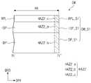
도 5a는 도 4b에 도시된 절단선 I-I'에 따라 폴딩 영역을 절단한 단면도이고, 도 5b는 도 4b에 도시된 절단선 ⅡⅡ에 따라 비폴딩 영역을 절단한 단면도이다.FIG. 5A is a cross-sectional view of the folding area taken along the cutting line I-I' shown in FIG. 4B, and FIG. 5B is a cross-sectional view of the non-folding area taken along the cutting line IIII of FIG. 4B.
도 4b 내지 도 5b를 참조하면, 표시 장치(DD)의 측면(DD_S) 중 폴딩 영역(FA)과 중첩하는 측면을 제1 장치 측면(DD_S1)이라 한다. 제1 장치 측면(DD_S1)은 제1 모듈 측면(DM_S1) 및 제1 윈도우 측면(WM_S1)을 포함한다. 표시 장치(DD)의 측면(DD_S) 중 비폴딩 영역(NFA)과 중첩하는 측면을 제2 장치 측면(DD_S2)이라 한다. 제2 장치 측면(DD_S2)은 제2 모듈 측면(DM_S2) 및 제2 윈도우 측면(WM_S2)을 포함한다.4B to 5B , a side overlapping the folding area FA among the side surfaces DD_S of the display device DD is referred to as a first device side surface DD_S1 . The first device side DD_S1 includes a first module side DM_S1 and a first window side WM_S1. A side overlapping the non-folding area NFA among the side surfaces DD_S of the display device DD is referred to as a second device side surface DD_S2 . The second device side DD_S2 includes a second module side DM_S2 and a second window side WM_S2.
표시 패널(DP)의 측면 중 폴딩 영역(FA)과 중첩하는 측면을 제1 패널 측면(DP_S1)이라 하고, 비폴딩 영역(NFA)와 중첩하는 측면을 제2 패널 측면(DP_S2)이라 한다. 입력 센서층(ISP)의 측면 중 폴딩 영역(FA)과 중첩하는 측면을 제1 센서 측면(ISP_S1)이라 하고, 비폴딩 영역(NFA)와 중첩하는 측면을 제2 센서 측면(ISP_S2)이라 한다. 반사 방지층(RPL)의 측면 중 폴딩 영역(FA)과 중첩하는 측면을 제1 반사 방지 측면(RPL_S1)이라 하고, 비폴딩 영역(NFA)와 중첩하는 측면을 제2 반사 방지 측면(RPL_S2)이라 한다.A side of the display panel DP overlapping the folding area FA is referred to as a first panel side surface DP_S1 , and a side overlapping the non-folding area NFA is referred to as a second panel side surface DP_S2 . A side of the input sensor layer ISP that overlaps the folding area FA is referred to as a first sensor side surface ISP_S1 , and a side that overlaps the non-folding area NFA is referred to as a second sensor side surface ISP_S2 . Among the side surfaces of the anti-reflection layer RPL, a side overlapping the folding area FA is referred to as a first anti-reflection side surface RPL_S1 , and a side overlapping the non-folding area NFA is referred to as a second anti-reflection side surface RPL_S2 . .
본 발명의 일 예로, 제1 모듈 측면(DM_S1)은 제1 패널 측면(DP_S1), 제1 센서 측면(ISP_S1) 및 제1 반사 방지 측면(RPL_S1)을 포함한다. 또한 제2 모듈 측면(DM_S2)은 제2 패널 측면(DP_S2), 제2 센서 측면(ISP_S2) 및 제2 반사 방지 측면(RPL_S2)를 포함한다.As an example of the present invention, the first module side surface DM_S1 includes a first panel side surface DP_S1 , a first sensor side surface ISP_S1 , and a first anti-reflection side surface RPL_S1 . In addition, the second module side surface DM_S2 includes a second panel side surface DP_S2 , a second sensor side surface ISP_S2 , and a second anti-reflection side surface RPL_S2 .
다만 표시 패널(DP)과 입력 센서층(ISP) 사이에 접착층이 개재되거나, 또는 입력 센서층(ISP)과 반사 방지층(RPL) 사이에 접착층이 개재되는 경우 제1 및 제2 모듈 측면들(DM_S1, DM_S2)은 접착층의 측면을 더 포함할 수 있다.However, when an adhesive layer is interposed between the display panel DP and the input sensor layer ISP or an adhesive layer is interposed between the input sensor layer ISP and the anti-reflection layer RPL, the first and second module side surfaces DM_S1 , DM_S2) may further include a side surface of the adhesive layer.
가공된 표면에 생기는 불규칙적인 패턴의 정도를 표면조도(surface roughness)라고 할 때, 제1 윈도우 측면(WM_S1)은 제1 윈도우 표면조도(WM_SR1)을 갖고 제2 윈도우 측면(WM_S2)은 제2 윈도우 표면조도(WM_SR2)을 갖는다.When the degree of the irregular pattern generated on the processed surface is referred to as surface roughness, the first window side surface WM_S1 has the first window surface roughness WM_SR1 and the second window side surface WM_S2 has the second window surface roughness. It has a surface roughness (WM_SR2).
제1 윈도우 표면조도(WM_SR1)는 폴딩 영역(FA)에서 기준면(RS)으로부터 제1 윈도우 측면(WM_S1)까지의 높이의 평균값으로 정의될 수 있다. 제2 윈도우 표면조도(WM_SR2)는 비폴딩 영역(NFA)에서 기준면(RS)으로부터 제2 윈도우 측면(WM_S2)까지의 높이의 평균값으로 정의될 수 있다. 본 발명의 일 예로, 제1 윈도우 표면조도(WM_SR1)와 제2 윈도우 표면조도(WM_SR2)는 동일할 수 있다.The first window surface roughness WM_SR1 may be defined as an average value of heights from the reference plane RS to the first window side surface WM_S1 in the folding area FA. The second window surface roughness WM_SR2 may be defined as an average value of heights from the reference plane RS to the second window side surface WM_S2 in the non-folding area NFA. As an example of the present invention, the first window surface roughness WM_SR1 and the second window surface roughness WM_SR2 may be the same.
제1 모듈 측면(DM_S1)은 제1 모듈 표면조도(DM_SR1)을 갖고 제2 모듈 측면(DM_S2)은 제2 모듈 표면조도(DM_SR2)을 갖는다. 제1 모듈 표면조도(DM_SR1)는 폴딩 영역(FA)에서 기준면(RS)으로부터 제1 모듈 측면(DM_S1)까지의 높이의 평균값으로 정의될 수 있다. 제2 모듈 표면조도(DM_SR2)는 비폴딩 영역(NFA)에서 기준면(RS)으로부터 제2 모듈 측면(DM_S2)까지의 높이의 평균값으로 정의될 수 있다. 본 발명의 일 예로, 제1 모듈 표면조도(DM_SR1)은 제2 모듈 표면조도(DM_SR2)보다 낮을 수 있다.The first module side surface DM_S1 has a first module surface roughness DM_SR1 and the second module side surface DM_S2 has a second module surface roughness DM_SR2. The first module surface roughness DM_SR1 may be defined as an average value of heights from the reference plane RS to the first module side surface DM_S1 in the folding area FA. The second module surface roughness DM_SR2 may be defined as an average value of heights from the reference plane RS to the second module side surface DM_S2 in the non-folding area NFA. As an example of the present invention, the first module surface roughness DM_SR1 may be lower than the second module surface roughness DM_SR2.
제1 모듈 표면조도(DM_SR1)는 제1 패널 측면(DP_S1)의 표면조도(DP_SR1)인 제1 패널 표면조도(DP_SR1), 제1 센서 측면(ISP_S1)의 표면조도(ISP_SR1)인 제1 센서 표면조도(ISP_SR1) 및 제1 반사 방지 측면(RPL_S1)의 표면조도(RPL_SR1)인 제1 반사 방지 표면조도(RPL_SR1)의 평균값일 수 있다.The first module surface roughness DM_SR1 is the first panel surface roughness DP_SR1 which is the surface roughness DP_SR1 of the first panel side surface DP_S1, and the first sensor surface which is the surface roughness ISP_SR1 of the first sensor side surface ISP_S1. It may be an average value of the roughness ISP_SR1 and the first antireflection surface roughness RPL_SR1 which is the surface roughness RPL_SR1 of the first antireflection side surface RPL_S1.
제2 모듈 표면조도(DM_SR2)는 제2 패널 측면(DP_S2)의 표면조도(DP_SR2)인 제2 패널 표면조도(DP_SR2), 제2 센서 측면(ISP_S2)의 표면조도(ISP_SR2)인 제2 센서 표면조도(ISP_SR2) 및 제2 반사 방지 측면(RPL_S2)의 표면조도(RPL_SR2)인 제2 반사 방지 표면조도(RPL_SR2)의 평균값일 수 있다.The second module surface roughness DM_SR2 is the second panel surface roughness DP_SR2 which is the surface roughness DP_SR2 of the second panel side surface DP_S2, and the second sensor surface which is the surface roughness ISP_SR2 of the second sensor side surface ISP_S2. It may be an average value of the roughness ISP_SR2 and the second antireflection surface roughness RPL_SR2 which is the surface roughness RPL_SR2 of the second antireflection side surface RPL_S2.
본 발명의 일 예로, 제1 패널 표면조도(DP_SR1)은 제2 패널 표면조도(DP_SR2)보다 낮을 수 있다.As an example of the present invention, the first panel surface roughness DP_SR1 may be lower than the second panel surface roughness DP_SR2.
제1 센서 표면조도(ISP_SR1)은 제2 센서 표면조도(ISP_SR2)보다 낮을 수 있다.The first sensor surface roughness ISP_SR1 may be lower than the second sensor surface roughness ISP_SR2.
제1 반사 방지 표면조도(RPL_SR1)은 제2 반사 방지 표면조도(RPL_SR2)보다 낮을 수 있다.The first anti-reflection surface roughness RPL_SR1 may be lower than the second anti-reflection surface roughness RPL_SR2.
비폴딩 영역(NFA)과 중첩하는 제2 모듈 측면(DM_S2)은 제1 절단선(CL1, 도 7a 참조)을 따라서 실시된 제1 컷팅 공정에 의하여 가공 및 형성된다. 폴딩 영역(FA)과 중첩하는 제1 모듈 측면(DM_S1)은 제2 절단선(CL2, 도 8a 참조)을 따라서 실시된 제2 컷팅 공정에 의해 가공 및 형성된다.The second module side surface DM_S2 overlapping the non-folding area NFA is processed and formed by the first cutting process performed along the first cutting line CL1 (refer to FIG. 7A ). The first module side surface DM_S1 overlapping the folding area FA is processed and formed by a second cutting process performed along the second cutting line CL2 (refer to FIG. 8A ).
컷팅 공정을 통해 가공된 표면이 컷팅 과정에서 데미지를 받은 영역을 열화 영역(Heat affect zone, HAZ)라 한다. 열화 영역(HAZ)이 넓게 형성할수록 가공된 표면이 받은 데미지가 크고, 가공된 표면의 표면 조도가 클 수 있다.The area where the surface processed through the cutting process is damaged during the cutting process is called a heat affect zone (HAZ). The wider the degradation region HAZ is formed, the greater the damage to the processed surface and the greater the surface roughness of the processed surface.
본 발명의 일 예로, 제1 컷팅 공정에 의한 열화 영역을 제1 열화 영역(HAZ1), 제2 컷팅 공정에 의한 열화 영역을 제2 열화 영역(HAZ2)라 할 수 있다. 제1 방향(DR1)으로 의 제1 열화 영역(HAZ1)의 폭을 제1 열화 폭(HAW1), 제1 방향(DR1)으로의 제2 열화 영역(HAZ2)의 폭을 제2 열화 폭(HAW2)라 할 때, 제1 열화 폭(HAW1)은 제2 열화 폭(HAW2)보다 클 수 있다. 따라서 제1 컷팅 공정을 통해 가공된 제2 모듈 측면(DM_S2)의 제2 모듈 표면조도(DM_SR2)보다 제2 컷팅 공정을 통해 가공된 제1 모듈 측면(DM_S1)의 제1 모듈 표면조도(DM_SR1)가 낮을 수 있다.As an example of the present invention, the region deteriorated by the first cutting process may be referred to as a first deterioration region HAZ1 , and the region deteriorated by the second cutting process may be referred to as a second deterioration region HAZ2 . The width of the first deterioration region HAZ1 in the first direction DR1 is the first deterioration width HAW1 , and the width of the second deterioration region HAZ2 in the first direction DR1 is the second deterioration width HAW2 . ), the first deterioration width HAW1 may be greater than the second deterioration width HAW2. Therefore, the first module surface roughness (DM_SR1) of the first module side surface (DM_S1) processed through the second cutting process rather than the second module surface roughness (DM_SR2) of the second module side surface (DM_S2) processed through the first cutting process may be low.
이와 달리 제1 윈도우 측면(WM_S1)과 제2 윈도우 측면(WM_S2)은 동일한 컷팅 공정에 의해 형성될 수 있다. 따라서 제1 윈도우 측면(WM_S1)에 형성된 열화 영역(HAZ3)의 제1 방향(DR1)으로의 폭(HAW3)과 제2 윈도우 측면(WM_S2)에 형성된 열화 영역(HAZ3)의 제1 방향(DR1)으로 폭(HAW3)은 같을 수 있다. 따라서 제1 윈도우 측면(WM_S1)은 제2 윈도우 측면(WM_S2)과 같은 크기의 표면 조도를 가질 수 있다.Alternatively, the first window side WM_S1 and the second window side WM_S2 may be formed by the same cutting process. Accordingly, the width HAW3 of the deterioration region HAZ3 formed on the first window side surface WM_S1 in the first direction DR1 and the first direction DR1 of the deterioration region HAZ3 formed on the second window side surface WM_S2 . As a result, the width HAW3 may be the same. Accordingly, the first window side WM_S1 may have the same surface roughness as the second window side WM_S2 .
도 6은 폴딩 영역과 비폴딩 영역에 위치하는 표시 모듈의 측면을 촬영한 사진이다.6 is a photograph of side surfaces of a display module positioned in a folding area and a non-folding area.
도 6을 참조하면, 폴딩 영역(FA)에 위치하는 표시 모듈(DM)의 측면(DM_S1)은 제1 및 제2 비폴딩 영역들(NFA1/NFA2)에 위치하는 표시 모듈(DM)의 측면(DM_S2)보다 작은 표면 조도를 갖는다. 즉, 제1 모듈 측면(DM_S1)에는 비교적 작고 불규칙적인 요철이 형성된 반면, 제2 모듈 측면(DM_S2)에는 비교적 크고 불규칙적인 요철이 형성된다Referring to FIG. 6 , the side surface DM_S1 of the display module DM located in the folding area FA is the side surface (DM_S1) of the display module DM located in the first and second non-folding areas NFA1/NFA2. DM_S2) has a smaller surface roughness. That is, relatively small and irregular irregularities are formed on the first module side surface DM_S1 , while relatively large and irregular irregularities are formed on the second module side surface DM_S2 .
제2 모듈 측면(DM_S2)에는 크고 작은 검은색 도트들(BD)이 육안으로 시인된다. 여기서, 검은색 도트들(BD)은 제2 모듈 측면(DM_S2)이 오목하게 함몰된 부분일 수 있고, 검은색 도트들(BD) 주변의 비교적 밝은 부분은 제2 모듈 측면(DM_S2)이 볼록하게 돌출된 부분일 수 있다. 본 발명의 일 예로, 검은색 도트들(BD)은 반사 방지층(RPL, 도 5b 참조)에 위치할 수 있으나, 이에 한정되지 않는다. 검은색 도트들(BD)은 반사 방지층(RPL)은 물론 표시 패널(DP, 도 5b 참조) 또는 입력 센서층(ISP, 도 5b 참조)에 위치할 수도 있다.Large and small black dots BD are visually recognized on the second module side surface DM_S2 . Here, the black dots BD may be a portion in which the second module side surface DM_S2 is concavely recessed, and a relatively bright portion around the black dots BD may be a portion in which the second module side surface DM_S2 is convex. It may be a protruding part. As an example of the present invention, the black dots BD may be positioned on the anti-reflection layer RPL (refer to FIG. 5B ), but the present invention is not limited thereto. The black dots BD may be positioned on the display panel DP (refer to FIG. 5B ) or the input sensor layer (ISP, see FIG. 5B ) as well as the anti-reflection layer RPL.
반면, 제1 모듈 측면(DM_S1)은 위치에 따라 명암 차이가 크지 않으며, 검은색 도트들도 거의 시인되지 않는다. 따라서 제1 모듈 측면(DM_S1)은 제2 모듈 측면(DM_S2)보다 낮은 표면조도를 갖는 것을 확인할 수 있다.On the other hand, the contrast of the first module side surface DM_S1 is not large depending on the position, and the black dots are hardly recognized. Therefore, it can be seen that the first module side surface DM_S1 has a lower surface roughness than the second module side surface DM_S2.
도 7a 내지 도 7c는 본 발명에 따른 제1 컷팅 공정을 나타낸 공정도이고, 도 8a 내지 도 8c는 본 발명에 따른 제2 컷팅 공정을 나타낸 공정도이다.7A to 7C are process diagrams illustrating a first cutting process according to the present invention, and FIGS. 8A to 8C are process diagrams illustrating a second cutting process according to the present invention.
도 7a 내지 도 8c를 참조하면, 복수의 셀 영역들(CE)을 포함하는 모기판(MG)이 준비된다. 각각의 셀 영역들(CE)은 유효 영역(AA) 및 비유효 영역(NAA)을 포함한다.7A to 8C , a mother substrate MG including a plurality of cell regions CE is prepared. Each of the cell areas CE includes an effective area AA and an invalid area NAA.
각각의 셀 영역들(CE)을 둘러싼 제1 절단선(CL1)을 따라 제1 컷팅 공정을 실시하여 모기판(MG)으로부터 각 예비 표시 모듈(PDM)을 얻는다.Each preliminary display module PDM is obtained from the mother substrate MG by performing a first cutting process along the first cutting line CL1 surrounding each of the cell areas CE.
제1 컷팅 공정은 제1 파장을 가진 제1 레이저(LD1)을 이용하여 실시될 수 있다. 본 발명의 일 예로, 제1 레이저(LD1)는 이산화탄소를 매질로 하여 생성될 수 있고, 제1 파장은 1000 내지 1400㎚ 일 수 있다. 제1 컷팅 공정은 제1 레이저(LD1)을 n회 반복하여 조사하여 실시될 수 있다. 제1 레이저(LD1)는 제1 주파수로 조사될 수 있고, 제1 출력으로 조사될 수 있다.The first cutting process may be performed using the first laser LD1 having a first wavelength. As an example of the present invention, the first laser LD1 may be generated using carbon dioxide as a medium, and the first wavelength may be 1000 to 1400 nm. The first cutting process may be performed by repeatedly irradiating the first laser LD1 n times. The first laser LD1 may be irradiated with a first frequency and may be irradiated with a first output.
본 발명의 일 예로, 제1 컷팅 공정은 제1 레이저(LD1)의 위치를 고정한 채 모기판(MG)을 이동시켜 이루어질 수 있다.As an example of the present invention, the first cutting process may be performed by moving the mother substrate MG while the position of the first laser LD1 is fixed.
도 8a를 참조하면, 제1 컷팅 공정을 통해 얻어진 각 예비 표시 모듈(PDM)이 준비된다. 각 예비 표시 모듈(PDM)에 포함된 비유효 영역(NAA)과 유효 영역(AA)의 경계에 위치한 제2 절단선(CL2)을 따라 제2 컷팅 공정을 실시하여 유효 영역(AA)으로부터 비유효 영역(NAA)을 제거할 수 있다.Referring to FIG. 8A , each preliminary display module PDM obtained through the first cutting process is prepared. A second cutting process is performed along the second cutting line CL2 positioned at the boundary between the non-effective area NAA and the effective area AA included in each preliminary display module PDM to form a second cutting process from the effective area AA. Area (NAA) can be removed.
제2 컷팅 공정은 제1 파장과 다른 제2 파장을 가진 제2 레이저(LD2)을 이용하여 실시될 수 있다. 본 발명의 일 예로, 제2 파장은 제1 파장보다 작을 수 있다. 제2 파장은 300 내지 400㎚일 수 있다. 제2 컷팅 공정은 제2 레이저(LD2)을 m회 반복하여 조사하여 실시될 수 있다. 본 발명의 일 예로, m은 n보다 큰 자연수일 수 있다.The second cutting process may be performed using the second laser LD2 having a second wavelength different from the first wavelength. As an example of the present invention, the second wavelength may be smaller than the first wavelength. The second wavelength may be 300 to 400 nm. The second cutting process may be performed by repeatedly irradiating the second laser LD2 m times. As an example of the present invention, m may be a natural number greater than n.
제2 레이저(LD2)는 제2 주파수로 조사될 수 있다. 본 발명의 일 예로 제2 주파수는 제1 주파수보다 클 수 있다. 제2 레이저(LD2)는 제2 출력으로 조사될 수 있다. 본 발명의 일 예로, 제2 출력은 제1 출력보다 작을 수 있다.The second laser LD2 may be irradiated with a second frequency. As an example of the present invention, the second frequency may be greater than the first frequency. The second laser LD2 may be irradiated with a second output. As an example of the present invention, the second output may be smaller than the first output.
본 발명의 일 예로, 제2 컷팅 공정은 각 예비 표시 모듈(PDM)의 위치를 고정한 채 제2 레이저(LD2)를 이동시켜 이루어질 수 있다. 본 발명에 따르면 제2 레이저(LD2)는 제2 절단선(CL2)을 따라 제2 컷팅 공정을 실시할 수 있으면 충분하다. 즉, 예비 표시 모듈(PDM)의 크기가 증가하여도, 제2 절단선의 길이는 비유효 영역(NAA)과 유효 영역(AA)의 경계로 한정된다. 따라서, 예비 표시 모듈(PDM)의 사이즈가 변경되더라도, 제2 컷팅 공정을 실시하기 위한 설비를 교체할 필요가 없다. 또한, 제2 컷팅 공정이 유효 영역(AA)과 비유효 영역(NAA)이 접하는 부분에서만 진행되므로, 공정 시간을 단축시킬 있다.As an example of the present invention, the second cutting process may be performed by moving the second laser LD2 while fixing the position of each preliminary display module PDM. According to the present invention, it is sufficient if the second laser LD2 can perform the second cutting process along the second cutting line CL2 . That is, even when the size of the preliminary display module PDM increases, the length of the second cutting line is limited to the boundary between the non-effective area NAA and the effective area AA. Therefore, even if the size of the preliminary display module PDM is changed, there is no need to replace the equipment for performing the second cutting process. In addition, since the second cutting process is performed only at a portion where the effective area AA and the non-effective area NAA contact each other, the process time may be shortened.
도 7b 및 도 7c를 참조하면, 모기판(MG)은 예비 표시 패널(PDP) 및 예비 입력 센서층(PIS)을 포함할 수 있다. 다만, 본 발명의 일 예로, 모기판(MG)은 예비 입력 센서층(PIS)을 포함하지 않을 수도 있다.7B and 7C , the mother substrate MG may include a preliminary display panel PDP and a preliminary input sensor layer PIS. However, as an example of the present invention, the mother substrate MG may not include the preliminary input sensor layer PIS.
제1 절단선(CL1)을 따라 제1 레이저(LD1)를 이용한 제1 컷팅 공정을 실시하여 얻어진 예비 표시 모듈(PDM)의 측면(PDM_S)에 인접해서 제1 열화 영역(HAZ1)이 형성된다. 제1 열화 영역(HAZ1)은 입력 센서층(ISP)의 측면에 인접하여 형성되는 제1 서브 열화 영역(HAZ1_a) 및 표시 패널(DP)의 측면에 인접하여 형성되는 제2 서브 열화 영역(HAZ1_b)를 포함한다. 제1 서브 열화 영역(HAZ1_a) 및 제2 서브 열화 영역(HAZ1_a)의 제1 방향(DR1)으로의 폭은 같을 수 있다. 다만 입력 센서층(ISP) 및 표시 패널(DP)에 포함된 물질에 따라 제1 서브 열화 영역(HAZ1_a) 및 제2 서브 열화 영역(HAZ1_a)의 제1 방향(DR1)으로의 폭은 달라질 수 있다.A first deterioration region HAZ1 is formed adjacent to the side surface PDM_S of the preliminary display module PDM obtained by performing the first cutting process using the first laser LD1 along the first cutting line CL1 . The first degradation region HAZ1 includes a first sub degradation region HAZ1_a formed adjacent to a side surface of the input sensor layer ISP and a second sub degradation region HAZ1_b formed adjacent to a side surface of the display panel DP. includes The widths of the first sub-degradation region HAZ1_a and the second sub-degradation region HAZ1_a in the first direction DR1 may be the same. However, widths of the first sub-degradation region HAZ1_a and the second sub-degradation region HAZ1_a in the first direction DR1 may vary according to materials included in the input sensor layer ISP and the display panel DP. .
본 발명의 일 예로, 제1 방향(DR1)으로의 비유효 영역(NAA)의 폭(NAW, 도 9a 참조)은 제1 방향(DR1)으로의 제1 열화 영역(HAZ1)의 제1 열화 폭(HAW1, 도 9a 참조)보다 크거나 같을 수 있다.As an example of the present invention, the width (NAW) of the non-effective region NAA in the first direction DR1 (refer to FIG. 9A ) is the first deterioration width of the first deterioration region HAZ1 in the first direction DR1 . (HAW1, see FIG. 9A) may be greater than or equal to.
도 8b 및 도 8c를 참조하면, 각 예비 표시 모듈(P_DM, 도 7c 참조)은 반사 방지층(RPL)을 더 포함할 수 있다. 반사 방지층(RPL)은 입력 센서층(ISP) 상에 배치될 수 있다. 도 8b에는 반사 방지층(RPL)의 측면(RPL_S)에 발생한 제3 서브 열화 영역(HAZ1_c)의 제1 방향(DR1)으로의 폭이 제1 및 제2 서브 열화 영역(HAZ1_a, HAZ1_b)의 제1 방향(DR1)으로의 폭과 같도록 도시되어 있으나, 반사 방지층(RPL)에 포함된 물질에 따라 제3 서브 열화 영역(HAZ1_c)의 제1 방향(DR1)으로의 폭은 제1 및 제2 서브 열화 영역(HAZ1_a, HAZ1_b)의 제1 방향(DR1)으로의 폭과 다를 수 있다.Referring to FIGS. 8B and 8C , each preliminary display module P_DM (refer to FIG. 7C ) may further include an anti-reflection layer (RPL). The anti-reflection layer RPL may be disposed on the input sensor layer ISP. In FIG. 8B , the width in the first direction DR1 of the third sub-degradation region HAZ1_c generated on the side surface RPL_S of the anti-reflection layer RPL is the first of the first and second sub-deterioration regions HAZ1_a and HAZ1_b. Although illustrated to be the same as the width in the direction DR1 , the width of the third sub-degradation region HAZ1_c in the first direction DR1 may vary depending on the material included in the anti-reflection layer RPL. The widths of the deterioration regions HAZ1_a and HAZ1_b in the first direction DR1 may be different from each other.
제2 절단선(CL2)을 따라 제2 레이저(LD2)를 이용한 제2 컷팅 공정을 실시하여 예비 표시 모듈(PDM)의 유효 영역(AA)으로부터 비유효 영역(NAA)이 제거된 표시 모듈(DM)을 얻을 수 있다.The display module DM in which the non-effective area NAA is removed from the effective area AA of the preliminary display module PDM by performing a second cutting process using the second laser LD2 along the second cutting line CL2 ) can be obtained.
제2 컷팅 공정을 실시하여 얻어진 표시 모듈(DM)의 측면(DM_S2)에는 제2 열화 영역(HAZ2)이 형성된다. 제2 열화 영역(HAZ2)은 입력 센서층(ISP)의 측면에 인접하여 형성되는 제4 서브 열화 영역(HAZ2_a), 표시 패널(DP)의 측면에 인접하여 형성되는 제5 서브 열화 영역(HAZ2_b) 및 반사 방지층(RPL)의 측면에 인접하여 형성되는 제6 서브 열화 영역(HAZ2_c)을 포함한다. 제4 서브 열화 영역(HAZ2_a), 제5 서브 열화 영역(HAZ2_b) 및 제6 서브 열화 영역(HAZ2_c)의 제1 방향(DR1)으로의 폭은 서로 같을 수 있다. 다만 입력 센서층(ISP), 표시 패널(DP) 및 반사 방지층(RPL)에 포함된 물질에 따라 제4 서브 열화 영역(HAZ2_a), 제5 서브 열화 영역(HAZ2_b) 및 제6 서브 열화 영역(HAZ2_c)의 제1 방향(DR1)으로의 폭은 서로 달라질 수 있다.A second deterioration region HAZ2 is formed on the side surface DM_S2 of the display module DM obtained by performing the second cutting process. The second degradation region HAZ2 includes a fourth sub degradation region HAZ2_a formed adjacent to a side surface of the input sensor layer ISP and a fifth sub degradation region HAZ2_b formed adjacent to a side surface of the display panel DP. and a sixth sub-degradation region HAZ2_c formed adjacent to a side surface of the anti-reflection layer RPL. The widths of the fourth sub-degradation region HAZ2_a, the fifth sub-degradation region HAZ2_b, and the sixth sub-degradation region HAZ2_c in the first direction DR1 may be the same. However, depending on the materials included in the input sensor layer ISP, the display panel DP, and the anti-reflection layer RPL, the fourth sub-degradation region HAZ2_a, the fifth sub-degradation region HAZ2_b, and the sixth sub-degradation region HAZ2_c ) in the first direction DR1 may have different widths.
제2 컷팅 공정은, 제1 레이저(LD1)의 제1 출력에 비해 상대적으로 작은 출력인 제2 출력을 가진 제2 레이저(LD2)에 의해 실시되므로, 제2 열화 폭(HAW2, 도 5a 참조)은 제1 열화 폭(HAW1, 도 5b 참조)보다 작게 형성될 수 있다.Since the second cutting process is performed by the second laser LD2 having a second output that is relatively smaller than the first output of the first laser LD1 , the second degradation width HAW2 (refer to FIG. 5A ) may be formed to be smaller than the first degradation width HAW1 (refer to FIG. 5B ).
따라서, 유효 영역 및 표시 모듈(DM)의 임의의 영역으로부터 연장된 영역을 포함하도록 기 설정된 비유효 영역을 포함하는 예비 표시 모듈을 얻도록 제1 컷팅 공정을 실시한 후 제2 절단선(CL)을 따라 제2 컷팅 공정을 실시할 경우, 비유효 영역(NAA)과 맞닿은 유효 영역(AA)에는 제2 열화 영역(HAZ2)이 발생된 표시 모듈(DM)을 얻을 수 있다.Accordingly, after performing the first cutting process to obtain a preliminary display module including an effective area and an ineffective area preset to include an area extending from an arbitrary area of the display module DM, the second cutting line CL is cut. Accordingly, when the second cutting process is performed, the display module DM in which the second deterioration area HAZ2 is generated in the effective area AA in contact with the non-effective area NAA may be obtained.
본 발명의 일 예로, 비유효 영역(NAA)은 적어도 표시 모듈(DM)의 폴딩 영역(FA, 도 9a 참조)로부터 연장된 영역을 포함할 수 있다. 다만, 이에 한정되지 않고 비유효 영역(NAA)은 비폴딩 영역(NFA, 도 11a 참조) 중 일부로부터 연장된 영역을 포함할 수 있다.As an example of the present invention, the non-effective area NAA may include at least an area extending from the folding area FA (refer to FIG. 9A ) of the display module DM. However, the present invention is not limited thereto, and the non-effective area NAA may include an area extending from a part of the non-folding area NFA (refer to FIG. 11A ).
비유효 영역(NAA)이 폴딩 영역(FA)으로부터 연장된 영역을 포함할 경우, 제1 컷팅 공정만이 실시된 비폴딩 영역(NFA)에는 제1 열화 영역(HAZ1)이 형성되고, 제1 컷팅 공정 및 제2 컷팅 공정이 실시된 폴딩 영역(FA)에는 제2 열화 영역(HAZ2)이 형성된다. 따라서 제2 모듈 측면(DM_S2, 도 4b 참조)의 표면조도(DM_SR2)보다 제1 모듈 측면(DM_S1, 도 4b 참조)의 표면조도(DM_SR1)가 낮을 수 있다.When the ineffective area NAA includes an area extending from the folding area FA, the first deterioration area HAZ1 is formed in the non-folding area NFA where only the first cutting process is performed, and the first cutting process is performed. A second deterioration area HAZ2 is formed in the folding area FA where the process and the second cutting process have been performed. Therefore, the surface roughness DM_SR1 of the first module side (DM_S1, see FIG. 4B ) may be lower than the surface roughness DM_SR2 of the second module side (DM_S2, see FIG. 4B ).
따라서 반복되는 폴딩 동작으로 인해 제1 모듈 측면(DM_S1)에 스트레스에 가해져, 표시 모듈(DM)에 크랙 등이 발생해 손상되는 것을 방지할 수 있다. 그 결과 표시 장치(DD)의 제품 신뢰성을 향상시킬 수 있다.Therefore, it is possible to prevent the display module DM from being damaged due to the stress being applied to the side surface DM_S1 of the first module due to the repeated folding operation. As a result, product reliability of the display device DD may be improved.
도 9a 내지 도 12b는 본 발명의 일 실시예에 따른 제2 컷팅 공정을 설명하기 위한 평면도들이다.9A to 12B are plan views illustrating a second cutting process according to an embodiment of the present invention.
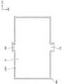
도 9a 및 도 9b를 참조하면, 비유효 영역(NAA)은 직사각형의 형상을 가질 수 있다. 제2 절단선(CL2)은 비유효 영역(NAA)과 유효 영역(AA)의 경계에 위치한다.9A and 9B , the ineffective area NAA may have a rectangular shape. The second cutting line CL2 is positioned at the boundary between the non-effective area NAA and the effective area AA.
유효 영역(AA)에는 표시 영역(DA) 및 비표시 영역(NDA)이 포함된다. 표시 모듈(DM)은 제1 오목부(HM1)을 포함할 수 있다. 제1 오목부(HM1)는 제2 컷팅 공정을 통해 유효 영역(AA)으로부터 비유효 영역(NAA)이 제거되어 형성될 수 있다. 제1 오목부(HM1)는 직사각형 형상을 갖는 비유효 영역(NAA)에 대응하여 직사각형 형상을 가질 수 있다.The effective area AA includes a display area DA and a non-display area NDA. The display module DM may include a first concave portion HM1 . The first concave portion HM1 may be formed by removing the ineffective area NAA from the effective area AA through a second cutting process. The first concave portion HM1 may have a rectangular shape corresponding to the non-effective area NAA having a rectangular shape.
본 발명의 일 예로, 비유효 영역(NAA)이 폴딩 영역(FA)으로부터 연장된 영역을 포함하는 경우, 제1 오목부(HM1)는 폴딩 영역(FA)으로부터 연장된 영역에 위치할 수 있다.As an example of the present invention, when the non-effective area NAA includes an area extending from the folding area FA, the first concave portion HM1 may be located in the area extending from the folding area FA.
표시 모듈(DM)은 기준 방향으로 비폴딩 영역(NFA)에서 제3 폭(W3)을 갖고, 폴딩 영역(FA)에서 제4 폭(W4)을 갖는다. 본 발명의 일 예로, 표시 모듈(DM)이 제1 오목부(HM1)를 포함할 경우, 제4 폭(W4)은 제3 폭(W3)보다 작을 수 있다.The display module DM has a third width W3 in the non-folding area NFA and a fourth width W4 in the folding area FA in the reference direction. As an example of the present invention, when the display module DM includes the first concave portion HM1 , the fourth width W4 may be smaller than the third width W3 .
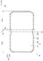
도 10a 및 도 10b를 참조하면, 비유효 영역(NAA)은 다각형의 형상을 가질 수 있다. 본 발명의 일 예로, 비유효 영역(NAA)은 사다리꼴의 형상을 가질 수 있다.10A and 10B , the ineffective area NAA may have a polygonal shape. As an example of the present invention, the ineffective area NAA may have a trapezoidal shape.
표시 모듈(DM)은 제2 오목부(HM2)를 포함할 수 있다. 제2 오목부(HM2)는 사다리꼴 형상을 갖는 비유효 영역(NAA)에 대응하여 사다리꼴 형상을 가질 수 있다.The display module DM may include a second concave portion HM2 . The second concave portion HM2 may have a trapezoidal shape corresponding to the non-effective area NAA having a trapezoidal shape.
본 발명의 일 예로, 비유효 영역(NAA)이 폴딩 영역(FA)으로부터 연장된 영역을 포함하는 경우, 제2 오목부(HM2)는 폴딩 영역(FA)으로부터 연장된 영역에 위치할 수 있다.As an example of the present invention, when the non-effective area NAA includes an area extending from the folding area FA, the second concave portion HM2 may be located in the area extending from the folding area FA.
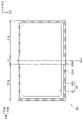
도 11a 및 도 11b를 참조하면, 비유효 영역(NAA)은 폴딩 영역(FA)으로부터 연장된 영역인 제1 비유효 영역(NAA_a) 및 비폴딩 영역(NFA) 중 일부인 모서리 부분으로부터 연장된 영역인 제2 비유효 영역(NAA_b)를 포함한다. 제1 및 제2 비유효 영역(NAA_a, NAA_b) 중 적어도 하나의 영역은 곡면 형상을 포함할 수 있다.11A and 11B , the non-effective area NAA is an area extending from a corner portion that is a part of the first non-effective area NAA_a which is an area extending from the folding area FA and the non-folding area NFA. The second non-effective area NAA_b is included. At least one of the first and second non-effective areas NAA_a and NAA_b may have a curved shape.
제2 절단선(CL2)은 유효 영역(AA)과 제1 비유효 영역(NAA_a)의 경계에 위치하는 제1 서브 절단선(CL2_a) 및 유효 영역(AA)과 제2 비유효 영역(NAA_b)의 경계에 위치하는 제2 서브 절단선(CL2_b)를 포함한다.The second cutting line CL2 is a first sub-cutting line CL2_a positioned at a boundary between the effective area AA and the first non-effective area NAA_a, and the effective area AA and the second non-effective area NAA_b. and a second sub-cutting line CL2_b positioned at the boundary of .
표시 모듈(DM)은 제3 오목부(HM3)을 포함할 수 있다. 제3 오목부(HM3)은 제2 컷팅 공정을 통해 유효 영역(AA)으로부터 제1 비유효 영역(NAA_a)이 제거되어 형성될 수 있다. 제3 오목부(HM3)은 곡면 형상을 갖는 제1 비유효 영역(NAA_a)에 대응하여 곡면 형상을 가질 수 있다.The display module DM may include a third concave portion HM3 . The third concave portion HM3 may be formed by removing the first non-effective area NAA_a from the effective area AA through a second cutting process. The third concave portion HM3 may have a curved shape corresponding to the first non-effective area NAA_a having a curved shape.
본 발명의 일 예로, 표시 모듈(DM)은 모서리 부분에 곡면 형상을 가질 수 있다. 상기한 곡면 형상은 제2 컷팅 공정을 통해 유효 영역(AA)으로부터 제2 비유효 영역(NAA_b)이 제거되어 형성될 수 있다. 제1 비유효 영역(NAA_a) 외에 제2 비유효 영역(NAA_b)을 포함하도록 비유효 영역(NAA)을 설정할 경우, 제2 컷팅 공정을 통해 폴딩 동작 시 표시 모듈(DM)이 손상되는 것을 방지하는 것 외에도 원하는 표시 모듈(DM)의 형상을 얻을 수 있다.As an example of the present invention, the display module DM may have a curved shape at a corner portion. The curved shape may be formed by removing the second ineffective area NAA_b from the effective area AA through a second cutting process. When the non-effective area NAA is set to include the second non-effective area NAA_b in addition to the first non-effective area NAA_a, the second cutting process prevents the display module DM from being damaged during the folding operation. In addition, a desired shape of the display module DM may be obtained.
도 12a 및 도 12b를 참조하면, 비유효 영역(NAA)은 폴딩 영역(FA)으로부터 연장되고, 유효 영역(AA)으로부터 돌출된 형상을 가질 수 있다. 본 발명의 일 예로, 비유효 영역(NAA)은 곡면 형상을 가지며 돌출될 수도 있다.12A and 12B , the non-effective area NAA may extend from the folding area FA and may have a shape protruding from the effective area AA. As an example of the present invention, the ineffective area NAA may have a curved shape and may protrude.
비유효 영역(NAA)이 유효 영역(AA)으로부터 돌출된 형상을 가질 경우, 표시 모듈(DM)은 오목부를 포함하지 않을 수 있다. 제2 컷팅 공정을 통해 비유효 영역(NAA)이 제거된 표시 모듈(DM)은 직사각형 형상을 가질 수 있다. 다만 이 경우에도 표시 모듈(DM)의 측면(DM_S, 도 4b 참조) 중 폴딩 영역(FA)과 중첩하는 제1 모듈 측면(DM_S1)은 비폴딩 영역(NFA)과 중첩하는 제2 모듈 측면(DM_S2)에 비해 상대적으로 낮은 표면 조도를 가질 수 있다. 따라서 폴딩 동작 시 표시 모듈(DM)이 손상되는 것을 방지하여 제품 신뢰성을 향상시킬 수 있다.When the non-effective area NAA has a shape protruding from the effective area AA, the display module DM may not include a concave portion. The display module DM from which the ineffective area NAA is removed through the second cutting process may have a rectangular shape. However, even in this case, the first module side surface DM_S1 overlapping the folding area FA among the side surfaces DM_S (refer to FIG. 4B ) of the display module DM overlaps the non-folding area NFA and the second module side surface DM_S2 overlapping the non-folding area NFA. ) may have a relatively low surface roughness compared to Accordingly, it is possible to prevent the display module DM from being damaged during the folding operation, thereby improving product reliability.
이상에서는 본 발명의 바람직한 실시예를 참조하여 설명하였지만, 해당 기술 분야의 숙련된 당업자 또는 해당 기술 분야에 통상의 지식을 갖는 자라면, 후술될 특허청구범위에 기재된 본 발명의 사상 및 기술 영역으로부터 벗어나지 않는 범위 내에서 본 발명을 다양하게 수정 및 변경시킬 수 있음을 이해할 수 있을 것이다.Although the above has been described with reference to the preferred embodiment of the present invention, those skilled in the art or those having ordinary knowledge in the technical field will not depart from the spirit and technical scope of the present invention described in the claims to be described later. It will be understood that various modifications and variations of the present invention can be made without departing from the scope of the present invention.
따라서, 본 발명의 기술적 범위는 명세서의 상세한 설명에 기재된 내용으로 한정되는 것이 아니라 특허청구범위에 의해 정하여져야만 할 것이다.Accordingly, the technical scope of the present invention should not be limited to the contents described in the detailed description of the specification, but should be defined by the claims.
DD: 표시 장치DP: 표시 패널
DM: 표시 모듈FA: 폴딩 영역
NFA: 비폴딩 영역WM: 윈도우
FX: 폴딩축RPL: 반사 방지층
W1~W4: 제1 내지 제4 폭HL: 오목부
TA: 투과 영역BZA: 베젤 영역
CL1: 제1 절단선CL2: 제2 절단선
PDM: 예비 표시 모듈AA: 유효 영역
NAA: 비 유효 영역SS1: 제1 측면
SS2: 제2 측면LD1: 제1 레이저
LD2: 제2 레이저DD: Display device DP: Display panel
DM: Display module FA: Folding area
NFA: non-folding area WM: window
FX: Folding axis RPL: Anti-reflection layer
W1 to W4: first to fourth widths HL: concave
TA: Transmissive area BZA: Bezel area
CL1: first cutting line CL2: second cutting line
PDM: Spare display module AA: Effective area
NAA: non-effective area SS1: first side
SS2: second side LD1: first laser
LD2: second laser
Claims (21)
Translated fromKorean상기 표시 패널 상에 배치되고, 상기 표시 패널을 따라 폴딩되는 윈도우를 포함하고,
상기 표시 패널의 측면은 상기 폴딩 영역에서 제1 표면 조도를 갖고, 상기 비폴딩 영역에서 제2 표면 조도를 가지며,
상기 제1 표면 조도는 상기 제2 표면 조도보다 낮고,
상기 윈도우의 측면은 상기 비폴딩 영역 및 상기 폴딩 영역에서 같은 표면 조도를 갖는 표시 장치.A display panel comprising: a display panel including a folding area folded about a folding axis and a non-folding area adjacent to the folding area; and
a window disposed on the display panel and folded along the display panel;
a side surface of the display panel has a first surface roughness in the folding area and a second surface roughness in the non-folding area;
The first surface roughness is lower than the second surface roughness,
A side surface of the window has the same surface roughness in the non-folding area and in the folding area.
상기 윈도우는 박막 글라스를 포함하는 표시 장치.The method of claim 1,
The window is a display device including thin glass.
상기 표시 패널 상에 배치되고, 상기 표시 패널을 따라 폴딩되는 반사 방지층을 더 포함하는 표시 장치.The method of claim 1,
and an anti-reflection layer disposed on the display panel and folded along the display panel.
상기 반사 방지층의 측면은 상기 폴딩 영역에서 제3 표면 조도를 갖고, 상기 비폴딩 영역에서 제4 표면 조도를 가지며,
상기 제3 표면 조도는 상기 제4 표면 조도보다 낮은 표시 장치.4. The method of claim 3,
A side surface of the anti-reflection layer has a third surface roughness in the folding area and a fourth surface roughness in the non-folding area,
The third surface roughness is lower than the fourth surface roughness.
상기 표시 패널은, 상기 폴딩 영역에서 오목부를 포함하고,
상기 폴딩 축과 평행한 방향을 기준 방향이라고 할 때,
상기 기준 방향으로 상기 비폴딩 영역에서 제1 폭을 갖고, 상기 폴딩 영역에서 제2 폭을 가지며,
상기 제2 폭은 상기 제1 폭보다 작은 표시 장치.The method of claim 1,
the display panel includes a concave portion in the folding area;
When a direction parallel to the folding axis is referred to as a reference direction,
It has a first width in the non-folding area in the reference direction and a second width in the folding area,
The second width is smaller than the first width.
상기 오목부는, 곡면 형상을 포함하는 표시 장치.6. The method of claim 5,
The concave portion includes a curved shape.
상기 기준 방향으로 상기 폴딩 영역과 상기 비폴딩 영역에서 같은 폭을 가지는 표시 장치.According to claim 5, wherein the window,
A display device having the same width in the folding area and the non-folding area in the reference direction.
빛을 투과하는 투과 영역 및 상기 투과 영역과 인접한 베젤 영역을 포함하고,
상기 오목부는, 상기 투과 영역과 비중첩하는 표시 장치.The method of claim 7, wherein the window,
a transmissive region that transmits light and a bezel region adjacent to the transmissive region;
The concave portion does not overlap the transmissive region.
상기 표시 패널 상에 배치되고, 상기 표시 패널을 따라 폴딩되는 윈도우를 포함하고,
상기 표시 패널의 측면은 제1 표면 조도를 갖는 제1 측면 및 상기 제1 표면 조도보다 높은 제2 표면 조도를 갖는 제2 측면을 포함하고,
상기 윈도우의 측면은 상기 비폴딩 영역 및 상기 폴딩 영역에서 같은 표면 조도를 갖고,
상기 제1 측면은, 상기 표시 패널의 측면 중 적어도 상기 폴딩 영역에서 중첩하는 측면을 포함하는 표시 장치.A display panel comprising: a display panel including a folding area folded about a folding axis and a non-folding area adjacent to the folding area; and
a window disposed on the display panel and folded along the display panel;
The side surface of the display panel includes a first side surface having a first surface roughness and a second side surface having a second surface roughness higher than the first surface roughness;
The side surface of the window has the same surface roughness in the non-folding area and the folding area,
The first side surface may include a side surface overlapping at least one of the side surfaces of the display panel in the folding area.
상기 윈도우는 박막 글라스를 포함하는 표시 장치.10. The method of claim 9,
The window is a display device including thin glass.
상기 제1 측면은 곡면 형상을 포함하는 표시 장치.10. The method of claim 9,
and the first side surface has a curved shape.
상기 제1 측면은, 상기 표시 패널의 측면 중 상기 비폴딩 영역 중 일부에서 중첩하는 측면을 더 포함하는 표시 장치.10. The method of claim 9,
The first side surface may further include a side surface overlapping a part of the non-folding area among side surfaces of the display panel.
상기 표시 패널 상에 배치되고, 상기 표시 패널을 따라 폴딩되는 반사 방지층을 더 포함하고,
상기 반사 방지층의 측면은 제3 표면 조도를 갖는 제3 측면 및 상기 제3 표면 조도보다 높은 제4 표면 조도를 갖는 제4 측면을 포함하고,
상기 제3 측면은 상기 제1 측면과 중첩하는 표시 장치.10. The method of claim 9,
an anti-reflection layer disposed on the display panel and folded along the display panel;
The side surface of the anti-reflection layer includes a third side surface having a third surface roughness and a fourth side surface having a fourth surface roughness higher than the third surface roughness,
The third side surface overlaps the first side surface.
상기 표시 모듈을 따라 폴딩되는 윈도우를 상기 표시 모듈 상에 배치하는 단계를 포함하고,
상기 표시 모듈을 제작하는 단계는,
유효 영역 및 비유효 영역을 포함하는 예비 표시 모듈을 둘러싼 제1 절단선을 따라 제1 컷팅 공정을 실시하여 모기판으로부터 예비 표시 모듈을 얻는 단계; 및
상기 비유효 영역과 상기 유효 영역의 경계에 위치하는 제2 절단선을 따라 제2 컷팅 공정을 실시하여 상기 유효 영역으로부터 상기 비유효 영역을 제거하는 단계를 포함하고,
상기 비유효 영역은, 적어도 상기 폴딩 영역으로부터 연장된 영역을 포함하는 표시장치의 제조 방법.manufacturing a display module including a folding area that is folded about a folding axis and a non-folding area adjacent to the folding area; and
arranging a window that is folded along the display module on the display module,
The manufacturing of the display module comprises:
obtaining a preliminary display module from a mother substrate by performing a first cutting process along a first cutting line surrounding the preliminary display module including the effective area and the non-effective area; and
removing the ineffective area from the effective area by performing a second cutting process along a second cutting line positioned at a boundary between the ineffective area and the effective area;
The non-effective area includes at least an area extending from the folding area.
상기 윈도우는 박막 글라스를 포함하는 표시장치의 제조 방법.15. The method of claim 14,
The window is a method of manufacturing a display device including thin glass.
상기 제1 컷팅 공정은 제1 파장을 가진 제1 레이저를 이용하고,
상기 제2 컷팅 공정은 상기 제1 파장과 다른 제2 파장을 가진 제2 레이저를 이용하는 표시장치의 제조 방법.15. The method of claim 14,
The first cutting process uses a first laser having a first wavelength,
The second cutting process is a method of manufacturing a display device using a second laser having a second wavelength different from the first wavelength.
상기 제1 컷팅 공정은, 상기 제1 레이저를 n회 반복하여 조사하는 공정을 포함하고,
상기 제2 컷팅 공정은, 상기 제2 레이저를 m회 반복하여 조사하는 공정을 포함하며,
m은 n보다 큰 자연수인 표시장치의 제조 방법.17. The method of claim 16,
The first cutting process includes a process of repeatedly irradiating the first laser n times,
The second cutting process includes a process of repeatedly irradiating the second laser m times,
A method of manufacturing a display device in which m is a natural number greater than n.
상기 제1 컷팅 공정에서 상기 제1 레이저는 제1 주파수로 조사되고,
상기 제2 컷팅 공정에서 상기 제2 레이저는 제2 주파수로 조사되며,
상기 제2 주파수는 상기 제1 주파수보다 큰 표시장치의 제조 방법.18. The method of claim 17,
In the first cutting process, the first laser is irradiated with a first frequency,
In the second cutting process, the second laser is irradiated with a second frequency,
The second frequency is greater than the first frequency.
상기 예비 표시 모듈 상에 반사 방지층을 배치하는 단계를 더 포함하는 표시장치의 제조 방법.The method of claim 14, wherein the manufacturing of the display module comprises:
and disposing an anti-reflection layer on the preliminary display module.
상기 표시 패널은, 상기 제2 커팅 공정을 통해 형성된 오목부를 포함하고,
상기 윈도우는,
빛을 투과하는 투과 영역 및 상기 투과 영역과 인접한 베젤 영역을 포함하고,
상기 오목부는 상기 투과 영역과 비중첩하는 표시장치의 제조 방법.15. The method of claim 14,
the display panel includes a recess formed through the second cutting process;
The window is
a transmissive region that transmits light and a bezel region adjacent to the transmissive region;
The concave portion does not overlap the transparent region.
상기 오목부는, 곡면 형상을 포함하는 표시장치의 제조 방법.21. The method of claim 20,
The concave portion may include a curved shape.
Priority Applications (3)
| Application Number | Priority Date | Filing Date | Title |
|---|---|---|---|
| KR1020210037484AKR20220132723A (en) | 2021-03-23 | 2021-03-23 | Display device and manufacturing method of the same |
| US17/697,835US12399527B2 (en) | 2021-03-23 | 2022-03-17 | Display device and manufacturing method thereof |
| CN202210271930.5ACN115116326A (en) | 2021-03-23 | 2022-03-18 | Display device |
Applications Claiming Priority (1)
| Application Number | Priority Date | Filing Date | Title |
|---|---|---|---|
| KR1020210037484AKR20220132723A (en) | 2021-03-23 | 2021-03-23 | Display device and manufacturing method of the same |
Publications (1)
| Publication Number | Publication Date |
|---|---|
| KR20220132723Atrue KR20220132723A (en) | 2022-10-04 |
Family
ID=83324635
Family Applications (1)
| Application Number | Title | Priority Date | Filing Date |
|---|---|---|---|
| KR1020210037484ACeasedKR20220132723A (en) | 2021-03-23 | 2021-03-23 | Display device and manufacturing method of the same |
Country Status (3)
| Country | Link |
|---|---|
| US (1) | US12399527B2 (en) |
| KR (1) | KR20220132723A (en) |
| CN (1) | CN115116326A (en) |
Family Cites Families (7)
| Publication number | Priority date | Publication date | Assignee | Title |
|---|---|---|---|---|
| KR100673073B1 (en) | 2000-10-21 | 2007-01-22 | 삼성전자주식회사 | Method and apparatus for cutting nonmetallic substrate using laser beam |
| JP2004272224A (en) | 2003-02-18 | 2004-09-30 | Sony Corp | Liquid crystal display device and its manufacturing method |
| KR20120119082A (en) | 2011-04-20 | 2012-10-30 | 엘지디스플레이 주식회사 | Method of cutting substrate for liquid crystal display devece |
| KR102601500B1 (en) | 2016-11-11 | 2023-11-15 | 삼성디스플레이 주식회사 | Display device and electronic device including the same |
| KR101984255B1 (en)* | 2017-10-20 | 2019-05-30 | 넥센타이어 주식회사 | Apparatus for manufacturing tire and method for manufacturing tire |
| KR102453147B1 (en) | 2017-12-11 | 2022-10-07 | 엘지디스플레이 주식회사 | Flexible display device |
| KR102733093B1 (en) | 2019-04-16 | 2024-11-25 | 삼성디스플레이 주식회사 | Display device and method of manufacturing the same |
- 2021
- 2021-03-23KRKR1020210037484Apatent/KR20220132723A/ennot_activeCeased
- 2022
- 2022-03-17USUS17/697,835patent/US12399527B2/enactiveActive
- 2022-03-18CNCN202210271930.5Apatent/CN115116326A/enactivePending
Also Published As
| Publication number | Publication date |
|---|---|
| US12399527B2 (en) | 2025-08-26 |
| US20220310980A1 (en) | 2022-09-29 |
| CN115116326A (en) | 2022-09-27 |
Similar Documents
| Publication | Publication Date | Title |
|---|---|---|
| KR102731698B1 (en) | Flexible display apparatus and electronic device comprising the same | |
| KR102369758B1 (en) | Defect inspection system | |
| KR102639429B1 (en) | Display device and manufacturing method of the same | |
| CN217821940U (en) | Display device and electronic device comprising same | |
| US20130162552A1 (en) | Touch devices and fabrication methods thereof | |
| US12342712B2 (en) | Display device and method for manufacturing the same | |
| KR20220158144A (en) | Window, display device including the same, and method of manufacturing window | |
| KR20220022939A (en) | Display device and electronic device having the same | |
| US20250271900A1 (en) | Display device and method of manufacturing the same | |
| KR102775200B1 (en) | Display device and manufacturing method of the same | |
| CN114078924A (en) | Display device and electronic apparatus | |
| US20250040067A1 (en) | Display device and manufacturing method for the same | |
| CN116312224A (en) | Window and display device including the same | |
| KR20220132723A (en) | Display device and manufacturing method of the same | |
| KR102864252B1 (en) | Method of manufacturing the electronic apparatus | |
| KR102774689B1 (en) | Foldable display device | |
| KR20220136540A (en) | Display device, method of manufacturing window, and method of manufacturing display device | |
| KR102388103B1 (en) | Recycle equipment for window panel and recycling mathod of window panel | |
| CN217551429U (en) | Display device | |
| US20250081367A1 (en) | Flexible display device and method of manufacturing display device | |
| US12377498B2 (en) | Manufacturing method of display device and display device manufactured by the method | |
| US20220242104A1 (en) | Dummy removal device and method of driving the same | |
| KR102792137B1 (en) | Display device and manufacturing method of display device | |
| US20230382097A1 (en) | Method of manufacturing display device and window | |
| CN116704903A (en) | windows and displays |
Legal Events
| Date | Code | Title | Description |
|---|---|---|---|
| PA0109 | Patent application | St.27 status event code:A-0-1-A10-A12-nap-PA0109 | |
| PG1501 | Laying open of application | St.27 status event code:A-1-1-Q10-Q12-nap-PG1501 | |
| P22-X000 | Classification modified | St.27 status event code:A-2-2-P10-P22-nap-X000 | |
| P22-X000 | Classification modified | St.27 status event code:A-2-2-P10-P22-nap-X000 | |
| A201 | Request for examination | ||
| PA0201 | Request for examination | St.27 status event code:A-1-2-D10-D11-exm-PA0201 | |
| D13-X000 | Search requested | St.27 status event code:A-1-2-D10-D13-srh-X000 | |
| E902 | Notification of reason for refusal | ||
| PE0902 | Notice of grounds for rejection | St.27 status event code:A-1-2-D10-D21-exm-PE0902 | |
| E13-X000 | Pre-grant limitation requested | St.27 status event code:A-2-3-E10-E13-lim-X000 | |
| P11-X000 | Amendment of application requested | St.27 status event code:A-2-2-P10-P11-nap-X000 | |
| PE0601 | Decision on rejection of patent | St.27 status event code:N-2-6-B10-B15-exm-PE0601 |