KR20220124749A - DIAGNOSTIC SYSTEMS AND METHODS INCLUDING TEMPERATURE-SENSING VASCULAR DEVICES - Google Patents
DIAGNOSTIC SYSTEMS AND METHODS INCLUDING TEMPERATURE-SENSING VASCULAR DEVICESDownload PDFInfo
- Publication number
- KR20220124749A KR20220124749AKR1020227026935AKR20227026935AKR20220124749AKR 20220124749 AKR20220124749 AKR 20220124749AKR 1020227026935 AKR1020227026935 AKR 1020227026935AKR 20227026935 AKR20227026935 AKR 20227026935AKR 20220124749 AKR20220124749 AKR 20220124749A
- Authority
- KR
- South Korea
- Prior art keywords
- catheter
- temperature
- tube
- temperature sensor
- blood
- Prior art date
- Legal status (The legal status is an assumption and is not a legal conclusion. Google has not performed a legal analysis and makes no representation as to the accuracy of the status listed.)
- Pending
Links
- 238000000034methodMethods0.000titleclaimsabstractdescription55
- 230000002792vascularEffects0.000titledescription3
- 230000006870functionEffects0.000claimsabstractdescription74
- 238000002405diagnostic procedureMethods0.000claimsabstractdescription56
- 238000012545processingMethods0.000claimsabstractdescription31
- 238000012544monitoring processMethods0.000claimsabstractdescription19
- 239000012530fluidSubstances0.000claimsdescription78
- 230000017531blood circulationEffects0.000claimsdescription71
- 239000008280bloodSubstances0.000claimsdescription47
- 210000004369bloodAnatomy0.000claimsdescription47
- 210000005166vasculatureAnatomy0.000claimsdescription37
- 238000004891communicationMethods0.000claimsdescription24
- 208000015181infectious diseaseDiseases0.000claimsdescription18
- 230000000747cardiac effectEffects0.000claimsdescription11
- 230000008859changeEffects0.000claimsdescription7
- 238000009529body temperature measurementMethods0.000claimsdescription6
- 238000012774diagnostic algorithmMethods0.000claimsdescription6
- 206010033675panniculitisDiseases0.000claimsdescription3
- 210000004304subcutaneous tissueAnatomy0.000claimsdescription3
- 238000012546transferMethods0.000abstractdescription3
- 238000011010flushing procedureMethods0.000description25
- RIBGNAJQTOXRDK-UHFFFAOYSA-N1,3-dichloro-5-(3-chlorophenyl)benzeneChemical compoundClC1=CC=CC(C=2C=C(Cl)C=C(Cl)C=2)=C1RIBGNAJQTOXRDK-UHFFFAOYSA-N0.000description22
- 230000008569processEffects0.000description15
- FAPWRFPIFSIZLT-UHFFFAOYSA-MSodium chlorideChemical compound[Na+].[Cl-]FAPWRFPIFSIZLT-UHFFFAOYSA-M0.000description13
- 238000001514detection methodMethods0.000description9
- 239000007924injectionSubstances0.000description9
- 238000002347injectionMethods0.000description9
- 239000011780sodium chlorideSubstances0.000description8
- QVGXLLKOCUKJST-UHFFFAOYSA-Natomic oxygenChemical compound[O]QVGXLLKOCUKJST-UHFFFAOYSA-N0.000description6
- 238000001802infusionMethods0.000description6
- 239000001301oxygenSubstances0.000description6
- 229910052760oxygenInorganic materials0.000description6
- 239000000523sampleSubstances0.000description6
- WQZGKKKJIJFFOK-GASJEMHNSA-NGlucoseNatural productsOC[C@H]1OC(O)[C@H](O)[C@@H](O)[C@@H]1OWQZGKKKJIJFFOK-GASJEMHNSA-N0.000description5
- 206010040047SepsisDiseases0.000description5
- 239000008103glucoseSubstances0.000description5
- 238000004382pottingMethods0.000description5
- 238000002604ultrasonographyMethods0.000description5
- 230000000712assemblyEffects0.000description4
- 238000000429assemblyMethods0.000description4
- 230000036760body temperatureEffects0.000description4
- 238000010586diagramMethods0.000description4
- 238000005286illuminationMethods0.000description4
- 238000003780insertionMethods0.000description4
- 230000037431insertionEffects0.000description4
- 238000007789sealingMethods0.000description4
- 238000003860storageMethods0.000description4
- JVTAAEKCZFNVCJ-UHFFFAOYSA-MLactateChemical compoundCC(O)C([O-])=OJVTAAEKCZFNVCJ-UHFFFAOYSA-M0.000description3
- 230000036757core body temperatureEffects0.000description3
- 238000003745diagnosisMethods0.000description3
- 239000007788liquidSubstances0.000description3
- 238000012986modificationMethods0.000description3
- 230000004048modificationEffects0.000description3
- AUGNBQPSMWGAJE-UHFFFAOYSA-N1,2,3-trichloro-4-(2,3-dichlorophenyl)benzeneChemical compoundClC1=C(Cl)C(Cl)=CC=C1C1=CC=CC(Cl)=C1ClAUGNBQPSMWGAJE-UHFFFAOYSA-N0.000description2
- 238000004458analytical methodMethods0.000description2
- 238000004873anchoringMethods0.000description2
- 230000005540biological transmissionEffects0.000description2
- 238000004364calculation methodMethods0.000description2
- 230000000295complement effectEffects0.000description2
- 230000000994depressogenic effectEffects0.000description2
- 239000000203mixtureSubstances0.000description2
- 230000002093peripheral effectEffects0.000description2
- 239000000243solutionSubstances0.000description2
- 208000036828Device occlusionDiseases0.000description1
- 238000004435EPR spectroscopyMethods0.000description1
- 239000004593EpoxySubstances0.000description1
- 229920000181Ethylene propylene rubberPolymers0.000description1
- 102000009123FibrinHuman genes0.000description1
- 108010073385FibrinProteins0.000description1
- BWGVNKXGVNDBDI-UHFFFAOYSA-NFibrin monomerChemical compoundCNC(=O)CNC(=O)CNBWGVNKXGVNDBDI-UHFFFAOYSA-N0.000description1
- HTTJABKRGRZYRN-UHFFFAOYSA-NHeparinChemical compoundOC1C(NC(=O)C)C(O)OC(COS(O)(=O)=O)C1OC1C(OS(O)(=O)=O)C(O)C(OC2C(C(OS(O)(=O)=O)C(OC3C(C(O)C(O)C(O3)C(O)=O)OS(O)(=O)=O)C(CO)O2)NS(O)(=O)=O)C(C(O)=O)O1HTTJABKRGRZYRN-UHFFFAOYSA-N0.000description1
- 206010037660PyrexiaDiseases0.000description1
- 206010053648Vascular occlusionDiseases0.000description1
- 239000000853adhesiveSubstances0.000description1
- 230000001070adhesive effectEffects0.000description1
- 230000002776aggregationEffects0.000description1
- 238000004220aggregationMethods0.000description1
- 238000013473artificial intelligenceMethods0.000description1
- 230000008901benefitEffects0.000description1
- 239000000356contaminantSubstances0.000description1
- 238000013500data storageMethods0.000description1
- 238000010790dilutionMethods0.000description1
- 239000012895dilutionSubstances0.000description1
- 239000003814drugSubstances0.000description1
- 229940079593drugDrugs0.000description1
- 230000005670electromagnetic radiationEffects0.000description1
- 229950003499fibrinDrugs0.000description1
- 239000007789gasSubstances0.000description1
- 229960002897heparinDrugs0.000description1
- 229920000669heparinPolymers0.000description1
- 239000003978infusion fluidSubstances0.000description1
- 238000001990intravenous administrationMethods0.000description1
- 238000002955isolationMethods0.000description1
- 238000005259measurementMethods0.000description1
- 230000005055memory storageEffects0.000description1
- 235000015097nutrientsNutrition0.000description1
- 230000000737periodic effectEffects0.000description1
- 150000003071polychlorinated biphenylsChemical class0.000description1
- 239000004814polyurethaneSubstances0.000description1
- 229920002635polyurethanePolymers0.000description1
- 230000029058respiratory gaseous exchangeEffects0.000description1
- 230000004044responseEffects0.000description1
- 230000000630rising effectEffects0.000description1
- 238000004513sizingMethods0.000description1
- 239000000126substanceSubstances0.000description1
- 230000008961swellingEffects0.000description1
- 210000001519tissueAnatomy0.000description1
- 208000021331vascular occlusion diseaseDiseases0.000description1
- 210000003462veinAnatomy0.000description1
- 230000000007visual effectEffects0.000description1
Images


Classifications
- A—HUMAN NECESSITIES
- A61—MEDICAL OR VETERINARY SCIENCE; HYGIENE
- A61B—DIAGNOSIS; SURGERY; IDENTIFICATION
- A61B5/00—Measuring for diagnostic purposes; Identification of persons
- A61B5/01—Measuring temperature of body parts ; Diagnostic temperature sensing, e.g. for malignant or inflamed tissue
- A—HUMAN NECESSITIES
- A61—MEDICAL OR VETERINARY SCIENCE; HYGIENE
- A61B—DIAGNOSIS; SURGERY; IDENTIFICATION
- A61B5/00—Measuring for diagnostic purposes; Identification of persons
- A61B5/0002—Remote monitoring of patients using telemetry, e.g. transmission of vital signals via a communication network
- A61B5/0004—Remote monitoring of patients using telemetry, e.g. transmission of vital signals via a communication network characterised by the type of physiological signal transmitted
- A61B5/0008—Temperature signals
- A—HUMAN NECESSITIES
- A61—MEDICAL OR VETERINARY SCIENCE; HYGIENE
- A61B—DIAGNOSIS; SURGERY; IDENTIFICATION
- A61B5/00—Measuring for diagnostic purposes; Identification of persons
- A61B5/01—Measuring temperature of body parts ; Diagnostic temperature sensing, e.g. for malignant or inflamed tissue
- A61B5/015—By temperature mapping of body part
- A—HUMAN NECESSITIES
- A61—MEDICAL OR VETERINARY SCIENCE; HYGIENE
- A61B—DIAGNOSIS; SURGERY; IDENTIFICATION
- A61B5/00—Measuring for diagnostic purposes; Identification of persons
- A61B5/02—Detecting, measuring or recording for evaluating the cardiovascular system, e.g. pulse, heart rate, blood pressure or blood flow
- A61B5/024—Measuring pulse rate or heart rate
- A—HUMAN NECESSITIES
- A61—MEDICAL OR VETERINARY SCIENCE; HYGIENE
- A61B—DIAGNOSIS; SURGERY; IDENTIFICATION
- A61B5/00—Measuring for diagnostic purposes; Identification of persons
- A61B5/02—Detecting, measuring or recording for evaluating the cardiovascular system, e.g. pulse, heart rate, blood pressure or blood flow
- A61B5/026—Measuring blood flow
- A61B5/029—Measuring blood output from the heart, e.g. minute volume
- A—HUMAN NECESSITIES
- A61—MEDICAL OR VETERINARY SCIENCE; HYGIENE
- A61B—DIAGNOSIS; SURGERY; IDENTIFICATION
- A61B5/00—Measuring for diagnostic purposes; Identification of persons
- A61B5/24—Detecting, measuring or recording bioelectric or biomagnetic signals of the body or parts thereof
- A—HUMAN NECESSITIES
- A61—MEDICAL OR VETERINARY SCIENCE; HYGIENE
- A61B—DIAGNOSIS; SURGERY; IDENTIFICATION
- A61B5/00—Measuring for diagnostic purposes; Identification of persons
- A61B5/24—Detecting, measuring or recording bioelectric or biomagnetic signals of the body or parts thereof
- A61B5/25—Bioelectric electrodes therefor
- A61B5/279—Bioelectric electrodes therefor specially adapted for particular uses
- A61B5/28—Bioelectric electrodes therefor specially adapted for particular uses for electrocardiography [ECG]
- A61B5/283—Invasive
- A—HUMAN NECESSITIES
- A61—MEDICAL OR VETERINARY SCIENCE; HYGIENE
- A61B—DIAGNOSIS; SURGERY; IDENTIFICATION
- A61B5/00—Measuring for diagnostic purposes; Identification of persons
- A61B5/24—Detecting, measuring or recording bioelectric or biomagnetic signals of the body or parts thereof
- A61B5/316—Modalities, i.e. specific diagnostic methods
- A61B5/318—Heart-related electrical modalities, e.g. electrocardiography [ECG]
- A—HUMAN NECESSITIES
- A61—MEDICAL OR VETERINARY SCIENCE; HYGIENE
- A61B—DIAGNOSIS; SURGERY; IDENTIFICATION
- A61B5/00—Measuring for diagnostic purposes; Identification of persons
- A61B5/68—Arrangements of detecting, measuring or recording means, e.g. sensors, in relation to patient
- A61B5/6846—Arrangements of detecting, measuring or recording means, e.g. sensors, in relation to patient specially adapted to be brought in contact with an internal body part, i.e. invasive
- A61B5/6847—Arrangements of detecting, measuring or recording means, e.g. sensors, in relation to patient specially adapted to be brought in contact with an internal body part, i.e. invasive mounted on an invasive device
- A61B5/6852—Catheters
- A—HUMAN NECESSITIES
- A61—MEDICAL OR VETERINARY SCIENCE; HYGIENE
- A61B—DIAGNOSIS; SURGERY; IDENTIFICATION
- A61B5/00—Measuring for diagnostic purposes; Identification of persons
- A61B5/68—Arrangements of detecting, measuring or recording means, e.g. sensors, in relation to patient
- A61B5/6846—Arrangements of detecting, measuring or recording means, e.g. sensors, in relation to patient specially adapted to be brought in contact with an internal body part, i.e. invasive
- A61B5/6867—Arrangements of detecting, measuring or recording means, e.g. sensors, in relation to patient specially adapted to be brought in contact with an internal body part, i.e. invasive specially adapted to be attached or implanted in a specific body part
- A61B5/6876—Blood vessel
- A—HUMAN NECESSITIES
- A61—MEDICAL OR VETERINARY SCIENCE; HYGIENE
- A61B—DIAGNOSIS; SURGERY; IDENTIFICATION
- A61B5/00—Measuring for diagnostic purposes; Identification of persons
- A61B5/74—Details of notification to user or communication with user or patient; User input means
- A61B5/742—Details of notification to user or communication with user or patient; User input means using visual displays
- A—HUMAN NECESSITIES
- A61—MEDICAL OR VETERINARY SCIENCE; HYGIENE
- A61B—DIAGNOSIS; SURGERY; IDENTIFICATION
- A61B5/00—Measuring for diagnostic purposes; Identification of persons
- A61B5/74—Details of notification to user or communication with user or patient; User input means
- A61B5/7475—User input or interface means, e.g. keyboard, pointing device, joystick
- A—HUMAN NECESSITIES
- A61—MEDICAL OR VETERINARY SCIENCE; HYGIENE
- A61B—DIAGNOSIS; SURGERY; IDENTIFICATION
- A61B2562/00—Details of sensors; Constructional details of sensor housings or probes; Accessories for sensors
- A61B2562/02—Details of sensors specially adapted for in-vivo measurements
- A61B2562/0271—Thermal or temperature sensors
Landscapes
- Health & Medical Sciences (AREA)
- Life Sciences & Earth Sciences (AREA)
- Engineering & Computer Science (AREA)
- Surgery (AREA)
- General Health & Medical Sciences (AREA)
- Biophysics (AREA)
- Biomedical Technology (AREA)
- Heart & Thoracic Surgery (AREA)
- Medical Informatics (AREA)
- Molecular Biology (AREA)
- Physics & Mathematics (AREA)
- Animal Behavior & Ethology (AREA)
- Pathology (AREA)
- Public Health (AREA)
- Veterinary Medicine (AREA)
- Cardiology (AREA)
- Physiology (AREA)
- Hematology (AREA)
- Computer Networks & Wireless Communication (AREA)
- Vascular Medicine (AREA)
- Measuring And Recording Apparatus For Diagnosis (AREA)
- Measuring Pulse, Heart Rate, Blood Pressure Or Blood Flow (AREA)
- Measurement And Recording Of Electrical Phenomena And Electrical Characteristics Of The Living Body (AREA)
Abstract
Translated fromKorean
Description
Translated fromKorean본 개시는 진단 시스템 및 방법에 관한 것으로, 보다 구체적으로 온도 감지 디바이스를 포함하는 진단 시스템 및 방법에 관한 것이다.The present disclosure relates to diagnostic systems and methods, and more particularly, to diagnostic systems and methods comprising a temperature sensing device.
피부 온도 탐침, 구강 온도계, 고막 온도계, 식도 온도 탐침, 직장 온도계, 온도-감지 방광 카테터, 또는 기타를 포함하는, 그러나 이에 제한되지 않는, 많은 수의 기존 온도 탐침 중 임의의 것에 의해서 환자의 체온이 측정될 수 있다. 효과적이기는 하지만, 전술한 온도 탐침은 일반적으로 특정 위치에서 특정 조직에 대한 온도 데이터를 즉각적으로 측정하고 제공하는 것으로 제한되고, 이는 환자의 치료에서 그러한 온도 탐침의 유용성을 제한한다. 환자 진단을 보조하기 위해서 그리고 치료 옵션을 확장하기 위해서 온도 데이터를 향상시키기 위한 향상 수단과 조합되는 하나 이상의 온도 센서를 갖춘 온도 탐침이 필요하다.The patient's body temperature is measured by any of a large number of existing temperature probes, including, but not limited to, skin temperature probes, oral thermometers, tympanic thermometers, esophageal temperature probes, rectal thermometers, temperature-sensing bladder catheters, or the like. can be measured. Although effective, the temperature probes described above are generally limited to immediately measuring and providing temperature data for specific tissues at specific locations, which limits the usefulness of such temperature probes in the treatment of patients. There is a need for a temperature probe with one or more temperature sensors in combination with enhancement means to enhance temperature data to aid in patient diagnosis and to expand treatment options.
전술한 문제를 해결하기 위해, 온도-감지 관내 디바이스를 포함하는 진단 시스템 및 방법이 본원에 개시된다.In order to address the aforementioned problems, a diagnostic system and method comprising a temperature-sensing endoluminal device are disclosed herein.
몇몇 실시형태에서, 카테터 조립체, 콘솔, 및 디스플레이 화면을 포함하는 진단 시스템이 본원에 개시된다. 카테터 조립체는 카테터 관, 카테터 관에 동작 가능하게 부착되는 허브, 허브에 동작 가능하게 부착되는 연장 레그, 및 하나의 온도 센서 또는 복수의 온도 센서를 포함한다. 카테터 관은 근위 단부와 원위 단부 사이에서 연장되는 적어도 하나의 루멘(lumen)을 형성한다. 허브 및 연장 레그는 카테터 관의 루멘과 유체 연통되는 적어도 하나의 유체 통로를 형성한다. 하나의 온도 센서가, 내부의 온도가 측정되도록 구성되는 카테터 관, 허브, 또는 연장 레그 내에 배치된다. 복수의 온도 센서가, 내부의 온도가 측정되도록 구성되는 카테터 관, 허브, 또는 연장 레그, 또는 이들의 조합 내에 배치된다. 콘솔은 카테터 조립체와 통신하도록 구성된다. 콘솔은 메모리 및 프로세서를 포함하고, 프로세서는, 카테터 관이 환자의 맥관 구조 내에 배치되어 있는 동안, 적어도 온도 데이터를 프로세싱하기 위한 하나 이상의 기능을 가지는 진단 프로세스를 예시하도록 구성된다. 디스플레이 화면은 콘솔과 통신하도록 구성된다. 디스플레이 화면은 하나 이상의 센서와 연관되는 온도 판독치를 적어도 하나 포함하는 그래픽 사용자 인터페이스("GUI")를 디스플레이하도록 구성된다.In some embodiments, disclosed herein is a diagnostic system comprising a catheter assembly, a console, and a display screen. The catheter assembly includes a catheter tube, a hub operatively attached to the catheter tube, an extension leg operatively attached to the hub, and a temperature sensor or plurality of temperature sensors. The catheter tube defines at least one lumen extending between the proximal end and the distal end. The hub and the extension leg define at least one fluid passageway in fluid communication with the lumen of the catheter tube. A temperature sensor is disposed within the catheter tube, hub, or extension leg that is configured to measure the temperature therein. A plurality of temperature sensors are disposed within the catheter tube, hub, or extension leg, or a combination thereof, configured to measure a temperature therein. The console is configured to communicate with the catheter assembly. The console includes a memory and a processor, wherein the processor is configured to instantiate a diagnostic process having one or more functions for processing at least temperature data while the catheter tube is placed in a vasculature of a patient. The display screen is configured to communicate with the console. The display screen is configured to display a graphical user interface (“GUI”) comprising at least one temperature reading associated with one or more sensors.
몇몇 실시형태에서, 콘솔은 콘솔 내로의 입력 및 콘솔로부터의 출력을 조정하도록 구성되는 디스플레이 서버를 예시하도록 구성된다. 입력은 진단 프로세스의 하나 이상의 기능의 선택을 포함한다. 출력은 GUI를 포함한다.In some embodiments, the console is configured to illustrate a display server configured to coordinate input into and output from the console. The input includes selection of one or more functions of the diagnostic process. The output includes the GUI.
몇몇 실시형태에서, 메모리는, 카테터 관이 환자의 맥관 구조 내에 배치되어 있는 동안, 진단 프로세스로 카테터 조립체의 임의의 온도 센서로부터의 온도 데이터를 프로세싱하기 위한 하나 이상의 온도 데이터-프로세싱 알고리즘을 포함한다.In some embodiments, the memory includes one or more temperature data-processing algorithms for processing temperature data from any temperature sensor of the catheter assembly into a diagnostic process while the catheter tube is placed within the vasculature of the patient.
몇몇 실시형태에서, 카테터 관은 복수의 온도 센서를 포함한다. 복수의 온도 센서의 각각의 온도 센서는 국소적인 온도를 측정하기 위해서 카테터 관의 길이를 따른 복수의 위치들 중 다른 위치에 배치된다.In some embodiments, the catheter tube includes a plurality of temperature sensors. Each temperature sensor of the plurality of temperature sensors is disposed at a different one of the plurality of locations along the length of the catheter tube to measure a local temperature.
몇몇 실시형태에서, 메모리는 카테터 관의 길이를 따른 복수의 위치 중 임의의 하나 이상의 위치에서 진단 프로세스로 환자의 맥관 구조 또는 피하 조직 내의 감염을 진단하기 위한 감염-진단 알고리즘을 포함한다. 감염-진단 알고리즘으로 감염을 진단하는 것은, 복수의 위치 중 하나 이상의 위치에서 온도 센서 또는 온도 센서들 각각의 국소적인 온도 변화 또는 그 추세에 따른다.In some embodiments, the memory comprises an infection-diagnostic algorithm for diagnosing an infection in a vasculature or subcutaneous tissue of a patient with a diagnostic process at any one or more of a plurality of locations along the length of the catheter tube. Diagnosing an infection with the infection-diagnostic algorithm is according to a local temperature change or trend of a temperature sensor or each of the temperature sensors at one or more of a plurality of locations.
몇몇 실시형태에서, 카테터 관은 카테터 관 내에 배치되는 적어도 하나의 카테터-관 온도 센서, 허브 내에 배치되는 적어도 하나의 허브 온도 센서, 또는 카테터 관, 허브 또는 카테터 관 및 허브 모두 내의 온도 측정을 위해서 구성되는 이들의 조합을 포함한다.In some embodiments, the catheter tube is configured for at least one catheter-tube temperature sensor disposed within the catheter tube, at least one hub temperature sensor disposed within the hub, or for temperature measurement within the catheter tube, hub, or both the catheter tube and the hub. combinations thereof are included.
몇몇 실시형태에서, 진단 프로세스의 하나 이상의 기능들은 플러싱-준수 기능(flushing-compliance function)을 포함한다. 플러싱-준수 기능은, 환자-온도 혈액이 카테터 조립체로부터 채취되는 후에 또는 권장 간격 또는 인스턴스(instance)에서 카테터 조립체를 통해서 플러시되는 상온 플러시액(flushate)으로부터 예상되는 바와 같은, 플러싱-준수 온도 변화가 카테터-관 온도 센서, 허브 온도 센서, 또는 카테터-관 온도 센서 및 허브 온도 센서 모두에서 발생되지 않을 때, 콘솔-기반 경고를 제공하도록 구성된다.In some embodiments, one or more functions of the diagnostic process include a flushing-compliance function. The flush-compliance function is such that the flush-compliance temperature change, as expected from a room temperature flushate that is flushed through the catheter assembly at recommended intervals or instances, after patient-temperature blood is drawn from the catheter assembly, is is configured to provide a console-based alert when not generated at the catheter-tube temperature sensor, the hub temperature sensor, or both the catheter-tube temperature sensor and the hub temperature sensor.
몇몇 실시형태에서, 카테터 관은 카테터 관 내에 배치되는 1차 카테터-관 온도 센서를 포함한다. 콘솔은 1차 카테터-관 온도 센서에 통신 가능하게 커플링되는 비례-적분-미분(proportional-integral-derivative, "PID") 제어기를 포함한다. PID 제어기는 혈액 온도보다 몇 도 높게 설정되는 온도에서 1차 카테터-관 온도 센서를 유지하도록 구성된다.In some embodiments, the catheter tube includes a primary catheter-tube temperature sensor disposed within the catheter tube. The console includes a proportional-integral-derivative (“PID”) controller communicatively coupled to the primary catheter-tube temperature sensor. The PID controller is configured to maintain the primary catheter-tube temperature sensor at a temperature that is set several degrees above the blood temperature.
몇몇 실시형태에서, 진단 프로세스의 하나 이상의 기능들은 혈액-유량 기능을 포함한다. 혈액-유량 기능에 따라, 진단 프로세스는, 혈액 온도보다 몇 도 높게 설정되는 온도에서 1차 카테터-관 온도 센서를 유지하는 데 필요한 전력의 양을 이용하여 1차 카테터-관 온도 센서에 관한 혈액 유량을 모니터링하기 위해서, 혈액-유량 알고리즘을 이용한다. 혈액 유량은 혈액 온도보다 몇 도 높게 설정되는 온도에서 1차 카테터-관 온도 센서를 유지하는 데 필요한 전력의 양에 비례한다.In some embodiments, one or more functions of the diagnostic process include a blood-flow function. Depending on the blood-flow function, the diagnostic process uses the amount of power required to maintain the primary catheter-tube temperature sensor at a temperature that is set several degrees above the blood temperature to determine the blood flow rate for the primary catheter-tube temperature sensor. To monitor the blood flow rate algorithm is used. The blood flow rate is proportional to the amount of power required to maintain the primary catheter-tube temperature sensor at a temperature set a few degrees above the blood temperature.
몇몇 실시형태에서, 진단 프로세스의 하나 이상의 기능들은 심장-매개변수 기능을 포함한다. 심장-매개변수 기능에 따라, 진단 프로세스는, 심장 박출량을 포함하는 심장 매개변수를 결정하기 위해서 심장-매개변수 알고리즘과 조합하여 혈액-유량 알고리즘을 이용한다.In some embodiments, the one or more functions of the diagnostic process include a cardiac-parameter function. Depending on the cardiac-parameter function, the diagnostic process uses the blood-flow algorithm in combination with the cardiac-parameter algorithm to determine cardiac parameters including cardiac output.
몇몇 실시형태에서, 진단 프로세스의 하나 이상의 기능들은 카테터-추적 기능을 포함한다. 카테터-추적 기능에 따라, 진단 프로세스는, 1차 카테터-관 온도 센서가 혈액 유동의 용적 증가(volumetric increase)에 따라 관내 접합부를 지나서 전진하는 때를 결정하기 위해서, 카테터-추적 알고리즘과 조합하여 혈액-유량 알고리즘을 이용한다.In some embodiments, one or more functions of the diagnostic process include a catheter-tracking function. In accordance with the catheter-tracking function, the diagnostic process is performed in combination with the catheter-tracking algorithm to determine when the primary catheter-tube temperature sensor is advanced past the endoluminal junction in response to a volumetric increase in blood flow. -Using the flow algorithm.
몇몇 실시형태에서, 진단 프로세스는 카테터-추적 알고리즘으로부터 초래되는 카테터-추적 데이터를 디스플레이 화면의 GUI에 출력되는 디스플레이-서버를 위한 디스플레이-서버 입력으로서 제공하도록 구성된다. GUI에 출력되는 디스플레이-서버는 임상의에게 환자의 맥관 구조 내의 카테터 관의 위치에 관한 표시를 제공한다.In some embodiments, the diagnostic process is configured to provide catheter-tracking data resulting from the catheter-tracking algorithm as display-server input for the display-server that is output to the GUI of the display screen. A display-server output to the GUI provides the clinician with an indication of the position of the catheter tube within the patient's vasculature.
몇몇 실시형태에서, 카테터 관은, 환자의 맥관 구조 내의 카테터 관의 위치 이상(malposition)을 결정하기 위해서 1차 카테터-관 온도 센서에 근접하여 카테터 관 내에 배치되는 2차 카테터-관 온도 센서를 포함한다.In some embodiments, the catheter tube comprises a secondary catheter-tube temperature sensor disposed within the catheter tube proximate the primary catheter-tube temperature sensor to determine a malposition of the catheter tube within the vasculature of the patient. do.
몇몇 실시형태에서, 카테터-추적 기능은 2차 카테터-관 온도 센서로부터의 온도 데이터에 따라 카테터의 위치 이상을 결정하도록 구성된다. 2차 카테터-관 온도 센서로부터의 온도 데이터는, 카테터 관이 혈액 유동에 대항하여(against) 이동되는 경우에 환자의 혈액 온도를 나타낸다. 2차 카테터-관 온도 센서로부터의 온도 데이터는, 혈액 온도보다 몇 도 높게 설정되는 온도의 1차 카테터-관 온도 센서로 인해, 카테터 관이 혈액 유동과 이동하는 경우에 상승되는 혈액 온도를 나타낸다.In some embodiments, the catheter-tracking function is configured to determine an anomaly in the position of the catheter according to temperature data from a secondary catheter-tube temperature sensor. The temperature data from the secondary catheter-tube temperature sensor is indicative of the patient's blood temperature when the catheter tube is moved against blood flow. The temperature data from the secondary catheter-tube temperature sensor indicates the elevated blood temperature as the catheter tube moves with the blood flow, due to the primary catheter-tube temperature sensor being set several degrees above the blood temperature.
몇몇 실시형태에서, 진단 시스템은 카테터 조립체 내에 내장되는 심전도("ECG") 스타일렛 또는 리드를 추가로 포함한다. 진단 프로세스의 하나 이상의 기능들은, ECG 스타일렛이 카테터 관 내에 배치되고 카테터 관이 환자의 맥관 구조 내에 배치되는 동안, ECG 데이터를 프로세싱하기 위한 ECG 기능을 포함한다. ECG 기능은 카테터 관의 선단부의 위치를 확인하고, 카테터 관의 선단부의 이동을 모니터링하고, 심박수를 결정하고, 또는 이들의 조합을 수행한다.In some embodiments, the diagnostic system further comprises an electrocardiogram (“ECG”) stylet or lead embedded within the catheter assembly. One or more functions of the diagnostic process include an ECG function for processing ECG data while an ECG stylet is placed within the catheter tube and the catheter tube is placed within a vasculature of a patient. The ECG function locates the tip of the catheter tube, monitors movement of the tip of the catheter tube, determines heart rate, or a combination thereof.
몇몇 실시형태에서, 관내 접근 디바이스, 콘솔, 및 디스플레이 화면을 포함하는 진단 시스템이 본원에서 또한 개시된다. 관내 접근 디바이스는 세장형 관(elongate tube) 및 하나의 온도 센서를 포함한다. 세장형 관은 세장형 관의 근위 단부와 원위 단부 사이에서 연장되는 적어도 하나의 루멘을 형성한다. 세장형 관의 원위-단부 부분 내에 배치되는 하나의 온도 센서는 내부의 온도를 측정하도록 구성된다. 콘솔은 관내 접근 디바이스와 통신하도록 구성된다. 콘솔은 메모리 및 프로세서를 포함하고, 프로세서는, 세장형 관의 원위-단부 부분이 환자의 맥관 구조 내에 배치되어 있는 동안, 적어도 온도 데이터를 프로세싱하기 위한 기능을 가지는 진단 프로세스를 예시하도록 구성된다. 콘솔은 온도 센서에 통신 가능하게 커플링되는 PID 제어기를 또한 포함한다. PID 제어기는 혈액 온도보다 몇 도 높게 설정되는 온도에서 온도 센서를 유지하도록 구성된다. 디스플레이 화면은 콘솔과 통신하도록 구성된다. 디스플레이 화면은,적어도, 온도 센서와 연관되는 온도 판독치를 포함하는 GUI를 디스플레이하도록 구성된다.In some embodiments, also disclosed herein is a diagnostic system comprising an intraluminal access device, a console, and a display screen. The intraluminal access device comprises an elongate tube and one temperature sensor. The elongate tube defines at least one lumen extending between the proximal end and the distal end of the elongate tube. One temperature sensor disposed within the distal-end portion of the elongate tube is configured to measure a temperature therein. The console is configured to communicate with the premises access device. The console includes a memory and a processor, wherein the processor is configured to instantiate a diagnostic process having functionality for processing at least temperature data while the distal-end portion of the elongate tube is disposed within a vasculature of a patient. The console also includes a PID controller communicatively coupled to the temperature sensor. The PID controller is configured to maintain the temperature sensor at a temperature that is set several degrees above the blood temperature. The display screen is configured to communicate with the console. The display screen is configured to display a GUI including at least a temperature reading associated with the temperature sensor.
몇몇 실시형태에서, 진단 프로세스의 기능은 혈액-유량 기능이다. 혈액-유량 기능에 따라, 진단 프로세스는, 혈액 온도보다 몇 도 높게 설정되는 온도에서 온도 센서를 유지하는 데 필요한 전력의 양을 이용하여 온도 센서에 관한 혈액 유량을 모니터링하기 위해서, 혈액-유량 알고리즘을 이용한다. 혈액 유량은 혈액 온도보다 몇 도 높게 설정되는 온도에서 온도 센서를 유지하는 데 필요한 전력의 양에 비례한다.In some embodiments, the function of the diagnostic process is a blood-flow function. Depending on the blood-flow function, the diagnostic process implements a blood-flow algorithm to monitor the blood flow rate relative to the temperature sensor using the amount of power required to maintain the temperature sensor at a temperature that is set several degrees above the blood temperature. use it Blood flow is proportional to the amount of power required to maintain the temperature sensor at a temperature set a few degrees above the blood temperature.
몇몇 실시형태에서, 콘솔은 콘솔 내로의 입력 및 콘솔로부터의 출력을 조정하도록 구성되는 디스플레이 서버를 예시하도록 구성된다. 입력은 혈액-유량 알고리즘으로부터 초래되는 혈액-유량 데이터로부터의 국소적인 최대치를 포함한다. 출력은 디스플레이 화면 상의 GUI 내의, 환자의 맥관 구조 내의 세장형 관의 원위-단부 부분의 성공적인 배치에 관한 표시를 포함한다.In some embodiments, the console is configured to illustrate a display server configured to coordinate input into and output from the console. The input includes local maxima from blood-flow data resulting from the blood-flow algorithm. The output includes an indication regarding successful placement of the distal-end portion of the elongate tube within the patient's vasculature, within the GUI on the display screen.
몇몇 실시형태에서, 적어도 온도 데이터를 프로세싱하기 위한 하나 이상의 기능을 가지는 진단 프로세스를 콘솔의 메모리 내에서 예시하는 예시 단계를 포함하는 진단 시스템의 방법이 본원에서 또한 개시된다. 방법은 또한 온도 데이터를 카테터 조립체로부터 콘솔에 전송하는 전송 단계를 포함한다. 카테터 조립체는 카테터 조립체의 카테터 관, 허브, 또는 연장 레그 내에 배치되는 하나의 온도 센서를 가진다. 대안적으로, 카테터 조립체는 카테터 관, 허브, 연장 레그, 또는 이들의 조합 내에 배치되는 복수의 온도 센서를 가진다. 방법은 또한 온도 데이터를 메모리에 로딩하는 로딩 단계를 포함한다. 방법은 또한 온도 데이터를 프로세싱하기 위한 하나 이상의 기능에 따라 콘솔의 프로세서로 온도 데이터를 프로세싱하는 프로세싱 단계를 포함한다. 방법은 또한, 적어도, 하나 이상의 센서와 연관되는 온도 판독치를 콘솔과 통신하도록 구성되는 디스플레이 화면 상의 GUI에서 디스플레이하는 디스플레이 단계를 포함한다.In some embodiments, also disclosed herein is a method of a diagnostic system comprising an illustrative step of illustrating in a memory of a console a diagnostic process having at least one or more functions for processing temperature data. The method also includes transmitting temperature data from the catheter assembly to the console. The catheter assembly has one temperature sensor disposed within the catheter tube, hub, or extension leg of the catheter assembly. Alternatively, the catheter assembly has a plurality of temperature sensors disposed within the catheter tube, hub, extension leg, or combination thereof. The method also includes a loading step of loading the temperature data into the memory. The method also includes a processing step of processing the temperature data with a processor of the console in accordance with the one or more functions for processing the temperature data. The method also includes displaying, in a GUI on a display screen, configured to communicate with the console the temperature readings associated with at least one or more sensors.
몇몇 실시형태에서, 방법은 또한 혈액-유량 알고리즘을 이용하는 혈액-유량 기능으로 환자의 맥관 구조 내에 배치되는 카테터 조립체의 임의의 온도 센서에 관한 혈액 유량을 모니터링하는 모니터링 단계를 포함한다. 혈액 유량은 혈액 온도보다 몇 도 높게 설정되는 온도에서 온도-센서를 유지하는 데 필요한 전력의 양에 비례한다.In some embodiments, the method also includes a monitoring step of monitoring blood flow rate relative to any temperature sensor of the catheter assembly disposed within the patient's vasculature in a blood-flow function using a blood-flow algorithm. The blood flow rate is proportional to the amount of power required to maintain the temperature-sensor at a temperature set a few degrees above the blood temperature.
본원에 제공되는 개념의 이러한 그리고 다른 특징은, 그러한 개념의 특정 실시형태를 더 구체적으로 설명하는 첨부 도면 및 이하의 설명을 통해 당업자에게 더 명확해질 것이다.These and other features of the concepts presented herein will become more apparent to those skilled in the art upon examination of the accompanying drawings and the following description, which more particularly set forth specific embodiments of such concepts.
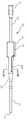
도 1은 몇몇 실시형태에 따른 카테터 조립체의 평면도를 제공한다.
도 2는 몇몇 실시형태에 따른 카테터 조립체의 평면도를 제공한다.
도 3은 몇몇 실시형태에 따른 카테터 조립체의 평면도를 제공한다.
도 4a 내지 도 4c는 몇몇 실시형태에 따른 카테터 고정 디바이스의 여러 도면을 제공한다.
도 5a 내지 도 5c는 몇몇 실시형태에 따른 카테터 고정 디바이스의 여러 도면을 제공한다.
도 6은 몇몇 실시형태에 따른 카테터 조립체의 사시도를 제공한다.
도 7은 몇몇 실시형태에 따른 카테터 조립체의 부분적 횡단면도를 제공한다.
도 8a 내지 도 8d는 몇몇 실시형태에 따른 초음파 신호 그래프의 여러 도면을 제공한다.
도 9a 및 도 9b는 몇몇 실시형태에 따른 카테터 조립체의 여러 도면을 제공한다.
도 10은 몇몇 실시형태에 따른 카테터 조립체의 허브의 부분적 횡단면도를 제공한다.
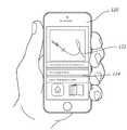
도 11은 몇몇 실시형태에 따른 스마트폰의 도면을 제공한다.
도 12는 몇몇 실시형태에 따른 카테터 조립체 및 보조 디바이스의 사시도를 제공한다.
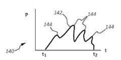
도 13은 몇몇 실시형태에 따른 카테터 조립체에 대한 압력 그래프를 제공한다.
도 14는 몇몇 실시형태에 따른 압력-감지 주사기의 부분적 횡단면도를 제공한다.
도 15는 몇몇 실시형태에 따른 압력-표시 카테터 조립체의 부분적 횡단면도를 제공한다.
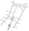
도 16은 몇몇 실시형태에 따른 카테터 조립체의 원위 부분의 도면을 제공한다.
도 17은 몇몇 실시형태에 따른 카테터 조립체의 원위 부분의 도면을 제공한다.
도 18은 몇몇 실시형태에 따른 카테터 조립체의 원위 부분의 사시도를 제공한다.
도 19는 몇몇 실시형태에 따른 루어 연결부(Luer connector)의 사시도를 제공한다.
도 20은 몇몇 실시형태에 따른 카테터 조립체의 루어 연결부의 사시도를 제공한다.
도 21은 몇몇 실시형태에 따른 카테터 조립체의 양분 허브의 사시도를 제공한다.
도 22는 몇몇 실시형태에 따른 카테터와 함께 이용하기 위한 펌프 시스템의 단순화되는 도면을 제공한다.
도 23은 도 22에 도시되는 펌프 시스템의 펌프 유닛의 측면도를 제공한다.
도 24는 몇몇 실시형태에 따른 유선 또는 무선 통신을 위해서 구성되는 카테터 조립체 및 콘솔을 포함하는 진단 시스템의 블록도를 제공한다.
도 25는 몇몇 실시형태에 따른, 환자에서의 사용 시의, 유선 통신을 위해서 구성되는 진단 시스템을 도시한다.
도 26은 몇몇 실시형태에 따른, 환자에서의 사용 시의, 무선 통신을 위해서 구성되는 진단 시스템을 도시한다.1 provides a top view of a catheter assembly in accordance with some embodiments.
2 provides a top view of a catheter assembly in accordance with some embodiments.
3 provides a top view of a catheter assembly in accordance with some embodiments.
4A-4C provide several views of a catheter fixation device in accordance with some embodiments.
5A-5C provide several views of a catheter fixation device in accordance with some embodiments.
6 provides a perspective view of a catheter assembly in accordance with some embodiments.
7 provides a partial cross-sectional view of a catheter assembly in accordance with some embodiments.
8A-8D provide several views of ultrasound signal graphs in accordance with some embodiments.
9A and 9B provide several views of a catheter assembly in accordance with some embodiments.
10 provides a partial cross-sectional view of a hub of a catheter assembly in accordance with some embodiments.
11 provides a diagram of a smartphone in accordance with some embodiments.
12 provides a perspective view of a catheter assembly and an assistive device in accordance with some embodiments.
13 provides a pressure graph for a catheter assembly in accordance with some embodiments.
14 provides a partial cross-sectional view of a pressure-sensitive syringe in accordance with some embodiments.
15 provides a partial cross-sectional view of a pressure-indicating catheter assembly in accordance with some embodiments.
16 provides views of a distal portion of a catheter assembly in accordance with some embodiments.
17 provides views of a distal portion of a catheter assembly in accordance with some embodiments.
18 provides a perspective view of a distal portion of a catheter assembly in accordance with some embodiments.
19 provides a perspective view of a Luer connector in accordance with some embodiments.
20 provides a perspective view of a luer connection of a catheter assembly in accordance with some embodiments.
21 provides a perspective view of a nutrient hub of a catheter assembly in accordance with some embodiments.
22 provides a simplified diagram of a pump system for use with a catheter in accordance with some embodiments.
23 provides a side view of a pump unit of the pump system shown in FIG. 22 .
24 provides a block diagram of a diagnostic system including a console and a catheter assembly configured for wired or wireless communication in accordance with some embodiments.
25 illustrates a diagnostic system configured for wired communication, when used in a patient, in accordance with some embodiments.
26 illustrates a diagnostic system configured for wireless communication, when used in a patient, in accordance with some embodiments.
본 개시는 2020년 1월 7일자로 출원된 미국 가출원 제62/958,299호의 우선권 이익을 주장하며, 그 전체가 본원에 참조로 포함된다.This disclosure claims the benefit of priority from U.S. Provisional Application No. 62/958,299, filed January 7, 2020, which is incorporated herein by reference in its entirety.
일부 특정 실시형태를 구체적으로 개시하기에 앞서, 본원에 개시되는 특정 실시형태가 본원에서 제공되는 개념의 범위를 제한하지 않는다는 것을 이해해야 한다. 또한, 본원에 개시되는 특정 실시형태가 특정 실시형태로부터 용이하게 분리될 수 있고, 선택적으로 본원에 개시되는 임의의 많은 다른 실시형태의 특징과 조합될 수 있거나 그러한 특징으로 대체될 수 있다는 것을 이해해야 한다.Before specifically disclosing some specific embodiments, it is to be understood that the specific embodiments disclosed herein do not limit the scope of the concepts provided herein. It should also be understood that certain embodiments disclosed herein may be readily separated from, and optionally combined with, or substituted for, features of any of many other embodiments disclosed herein. .
또한, 본원에서 사용되는 용어와 관련하여, 용어들은 일부 특정 실시형태를 설명하기 위한 것이고, 용어들은 본원에서 제공되는 개념의 범위를 제한하지 않는다는 것을 이해해야 한다. 서수(예를 들어, 제1, 제2, 제3 등)는 일반적으로 특징들 또는 단계들의 그룹 내에서 상이한 특징들 또는 단계들을 구별 또는 식별하기 위해서 사용되고, 일련적인 또는 수치적인 제한을 제공하지 않는다. 예를 들어, "제1", "제2", 및 "제3" 특징 또는 단계가 반드시 그러한 순서로 나타날 필요가 없고, 그러한 특징 또는 단계를 포함하는 특정 실시형태가 반드시 3개의 특징 또는 단계로 제한될 필요는 없다. "좌측", "우측", "상단", "하단", "전방", "후방", 및 기타와 같은 라벨은 편의를 위해서 사용되며, 예를 들어, 임의의 특정 고정 위치, 배향, 또는 방향을 암시하기 위한 것은 아니다. 그 대신, 그러한 라벨은, 예를 들어, 상대적인 위치, 배향, 또는 방향을 반영하기 위해서 사용된다. 문맥에서 달리 명백하게 기재되어 있지 않는 한, 단수 형태("a", "an", 및 "the")가 복수의 대상을 포함한다.Also, with respect to the terminology used herein, it is to be understood that the terminology is for the purpose of describing some specific embodiments, and the terminology does not limit the scope of the concepts provided herein. An ordinal number (eg, first, second, third, etc.) is generally used to distinguish or identify different features or steps within a group of features or steps, and does not provide a serial or numerical limitation. . For example, “first”, “second”, and “third” features or steps need not necessarily appear in that order, and a particular embodiment comprising such features or steps necessarily consists of the three features or steps. It need not be limited. Labels such as “left”, “right”, “top”, “bottom”, “front”, “rear”, and the like are used for convenience, for example, in any particular fixed position, orientation, or orientation. It is not intended to imply Instead, such labels are used, for example, to reflect relative position, orientation, or orientation. The singular forms "a", "an", and "the" include plural objects, unless the context clearly dictates otherwise.
"근위"와 관련하여, 예를 들어, 본원에 개시되는 카테터의 "근위 부분" 또는 "근위 단부 부분"은, 카테터가 환자에 대해서 사용될 때, 임상의에 근접하도록 의도되는 카테터의 부분을 포함한다. 마찬가지로, 예를 들어 카테터의 "근위 길이"는, 카테터가 환자에 대해서 사용될 때, 임상의에 근접하도록 의도되는 카테터의 길이를 포함한다. 예를 들어 카테터의 "근위 단부"는, 카테터가 환자에 대해서 사용될 때, 임상의에 근접하도록 의도되는 카테터의 단부를 포함한다. 카테터의 근위 부분, 근위-단부 부분, 또는 근위 길이는 카테터의 근위 단부를 포함할 수 있으나; 카테터의 근위 부분, 근위-단부 부분, 또는 근위 길이가 카테터의 근위 단부를 포함할 필요는 없다. 즉, 문맥에서 달리 제시되지 않는 한, 카테터의 근위 부분, 근위-단부 부분, 또는 근위 길이는 카테터의 말단 부분 또는 말단 길이가 아니다.With reference to “proximal”, for example, “proximal portion” or “proximal end portion” of a catheter as disclosed herein includes the portion of a catheter intended to be proximal to a clinician when the catheter is used on a patient. . Likewise, for example, the “proximal length” of a catheter includes the length of the catheter intended to approximate the clinician when the catheter is used on a patient. For example, the “proximal end” of a catheter includes the end of the catheter intended to be proximal to the clinician when the catheter is used against a patient. The proximal portion, proximal-end portion, or proximal length of the catheter may include the proximal end of the catheter; The proximal portion, proximal-end portion, or proximal length of the catheter need not include the proximal end of the catheter. That is, unless the context indicates otherwise, the proximal portion, proximal-end portion, or proximal length of the catheter is not the distal portion or distal length of the catheter.
"원위"와 관련하여, 예를 들어, 본원에 개시되는 카테터의 "원위 부분" 또는 "원위-단부 부분"은, 카테터가 환자에 대해서 사용될 때, 환자에 근접하도록 또는 환자 내에 위치되도록 의도되는 카테터의 부분을 포함한다. 마찬가지로, 예를 들어 카테터의 "원위 길이"는, 카테터가 환자에 대해서 사용될 때, 환자에 근접하도록 또는 환자 내에 위치되도록 의도되는 카테터의 길이를 포함한다. 예를 들어 카테터의 "원위 단부"는, 카테터가 환자에 대해서 사용될 때, 환자에 근접하도록 또는 환자 내에 위치되도록 의도되는 카테터의 단부를 포함한다. 카테터의 원위 부분, 원위-단부 부분, 또는 원위 길이는 카테터의 원위 단부를 포함할 수 있으나; 카테터의 원위 부분, 원위-단부 부분, 또는 원위 길이가 카테터의 원위 단부를 포함할 필요는 없다. 즉, 문맥에서 달리 제시되지 않는 한, 카테터의 원위 부분, 원위-단부 부분, 또는 원위 길이는 카테터의 말단 부분 또는 말단 길이가 아니다.With reference to “distal”, for example, a “distal portion” or “distal-end portion” of a catheter disclosed herein refers to a catheter intended to be positioned proximate to or within a patient when the catheter is used against a patient. includes part of Likewise, for example, a “distal length” of a catheter includes the length of a catheter intended to be positioned proximate to or within a patient when the catheter is used against a patient. For example, a “distal end” of a catheter includes the end of a catheter that is intended to be positioned proximate to or within a patient when the catheter is used against a patient. The distal portion, distal-end portion, or distal length of the catheter may include the distal end of the catheter; The distal portion, distal-end portion, or distal length of the catheter need not include the distal end of the catheter. That is, unless the context indicates otherwise, the distal portion, distal-end portion, or distal length of the catheter is not the distal portion or distal length of the catheter.
달리 규정되는 바가 없는 한, 본원에서 사용되는 모든 기술적 및 과학적 용어는 당업자에 의해서 일반적으로 이해되는 것과 동일한 의미를 가진다.Unless otherwise defined, all technical and scientific terms used herein have the same meaning as commonly understood by one of ordinary skill in the art.
환자의 신체 내의 관내 또는 다른 접근을 구축하기 위한 바늘 및 카테터 조립체와 같은 온도-감지 관내 디바이스를 포함하는 진단 시스템 및 방법이 본원에 개시된다. 관내 디바이스를 포함하는 진단 시스템을 이용하여, 관내 디바이스 및 이를 위한 고정 디바이스와 같은 상보적인 구성요소를 이하에서 먼저 설명한다. 마지막으로, 진단 시스템의 방법을 설명한다. 예시적인 조립체, 시스템, 및 센서가 미국 특허 제10,433,790호 및 미국 공개 제2019/0374162호에서 확인될 수 있고, 이들 각각은 그 전체가 본원에 참조로 포함된다.Disclosed herein are diagnostic systems and methods comprising temperature-sensing endoluminal devices, such as needle and catheter assemblies, for establishing endoluminal or other access within a patient's body. Using a diagnostic system comprising an intraluminal device, complementary components such as an intraluminal device and a fixation device therefor are first described below. Finally, the method of the diagnostic system is described. Exemplary assemblies, systems, and sensors can be found in US Pat. No. 10,433,790 and US Publication No. 2019/0374162, each of which is incorporated herein by reference in its entirety.
관내 디바이스 및 상보적인 구성요소Intraluminal devices and complementary components
관내 접근 디바이스는 카테터 조립체, 캐뉼라, 바늘, 또는 관내 삽입 또는 배치를 위해서 구성되는 세장형 관을 포함하는 다른 그러한 의료 디바이스를 포함한다. 카테터 조립체는 말초 삽입 중앙 카테터(peripherally inserted central catheter, "PICC"), 중앙 정맥 카테터(central venous catheter, "CVC"), 동맥 카테터, 폴리형(Foley-type) 요도 카테터, 또는 기타, 말초 정맥(peripheral intravenous, "IV") 카테터, 중앙선 카테터, 중간-체류 카테터, 공급 관, 또는 기타를 포함할 수 있고, 이들 중 일부를 이하에서 더 구체적으로 설명한다.An endoluminal access device includes a catheter assembly, cannula, needle, or other such medical device including an elongate tube configured for endoluminal insertion or placement. The catheter assembly may include a peripherally inserted central catheter (“PICC”), a central venous catheter (“CVC”), an arterial catheter, a Foley-type urethral catheter, or other, peripheral vein ( peripheral intravenous, “IV”) catheters, midline catheters, mid-retention catheters, supply tubes, or the like, some of which are described in more detail below.
관내 접근 디바이스가, 근위 단부와 원위 단부 사이에서 연장되는 적어도 하나의 루멘을 형성하는, 캐뉼라, 바늘, 또는 기타일 때, 세장형 관은, 관내 접근 디바이스가 환자 내에 배치될 때, 환자의 하나 이상의 생리학적 양태 또는 다른 매개변수, 또는 관내 접근 디바이스 자체의 물리적 양태 또는 그 동작을 모니터링할 수 있게 하는 하나 이상의 센서를 포함할 수 있다. 예를 들어, 관내 접근 디바이스는 내부의 온도 측정을 위해서 구성되는 세장형 관의 원위-단부 부분 내에 배치되는 하나의 온도 센서를 포함할 수 있다. 전술한 것에 대한 부가적인 상세 내용이 카테터 조립체-유형의 관내 접근 디바이스와 관련하여 이하에서 설명된다.When the endoluminal access device is a cannula, needle, or the like, defining at least one lumen extending between the proximal end and the distal end, the elongate tube, when the endoluminal access device is placed within the patient, is It may include one or more sensors that enable monitoring of physiological aspects or other parameters, or physical aspects of the endoluminal access device itself or its operation. For example, the intraluminal access device may include one temperature sensor disposed within the distal-end portion of the elongate tube configured for temperature measurement therein. Additional details to the foregoing are described below in relation to catheter assembly-type endoluminal access devices.
카테터 조립체는, 카테터 조립체가 환자 내에 배치될 때, 환자의 하나 이상의 생리학적 양태 또는 다른 매개변수, 또는 카테터 조립체 자체의 물리적 양태 또는 그 동작을 모니터링할 수 있게 하는 하나 이상의 센서를 구비한다. 그러한 양태는 중앙 정맥 압력, 체온, ECG 심장 신호, 산소 레벨, 초음파 데이터, 혈당, 등을 포함한다. 카테터 조립체와 함께 포함되는 센서(들)는 이러한 또는 다른 매개변수와 관련되는 데이터를 검출할 수 있도록 배치된다. 몇몇 실시형태에서, 하나 이상의 센서가 카테터 조립체의 허브 내에 또는 그에 근접하여 배치되나, 다양한 다른 위치도 가능하다. 또한, 예를 들어 무바늘 연결부와 같은, 카테터 조립체와 연관되는 다른 구성요소 및 구조물이 생리학적/물리적 양태를 모니터링하기 위한 하나 이상의 센서를 포함할 수 있다.The catheter assembly includes one or more sensors that enable monitoring of one or more physiological aspects or other parameters of the patient, or physical aspects of the catheter assembly itself or its operation, when the catheter assembly is placed in the patient. Such aspects include central venous pressure, body temperature, ECG cardiac signal, oxygen level, ultrasound data, blood sugar, and the like. The sensor(s) included with the catheter assembly are arranged to be able to detect data related to these or other parameters. In some embodiments, one or more sensors are disposed within or proximate to the hub of the catheter assembly, although a variety of other locations are possible. Additionally, other components and structures associated with the catheter assembly, such as, for example, needleless connections, may include one or more sensors for monitoring physiological/physical aspects.
또한, 카테터 조립체는 검출되는 생리학적/물리적 양태와 관련되는 데이터를, 본원에서 수령 위치로도 지칭되는, 다른 위치로 무선으로 전송하거나 달리 전달할 수 있는 능력을 포함한다. 데이터 수령 위치의 예는 환자 전자 의료 기록(electronic medical record, "EMR"), 환자 모니터링 기구, 스마트폰 또는 다른 모바일 디바이스, 태블릿, 저장 위치, 컴퓨터 서버, 간호사실, 또는 다양한 다른 목적지를 포함한다.The catheter assembly also includes the ability to wirelessly transmit or otherwise transmit data related to a detected physiological/physical aspect to another location, also referred to herein as a receiving location. Examples of data receiving locations include a patient electronic medical record (“EMR”), patient monitoring instrument, smartphone or other mobile device, tablet, storage location, computer server, nurse's office, or various other destinations.
몇몇 실시형태에 따른, 전반적으로 10으로 표시되는, 카테터 조립체("카테터")의 여러 상세 부분을 도시하는 도 1을 먼저 참조한다. 도시되는 바와 같이, 카테터(10)는, 카테터 관(12)의 근위 단부와 원위 단부(13) 사이에서 연장되는 하나 이상의 루멘(14)을 형성하는 세장형 카테터 관(12)을 포함한다. 카테터 관의 근위 단부는 허브(16)에 동작 가능하게 연결되고, 허브는 다시, 카테터 조립체(10)를 통한 하나 이상의 유체 통로의 나머지를 통해서 하나 이상의 루멘(14)을 연장시키는 하나 이상의 연장 레그(18)에 동작 가능하게 연결된다. 루어 연결부와 같은 연결부(20)가 연장 레그(18)의 근위 단부에 배치된다. 허브(16)는 허브(16)의 본체로부터 대향되게 연장되는 2개의 봉합 날개부(suture wing)(22)를 포함한다. 각각의 봉합 날개부(22)는 봉합 홀(24)을 포함한다. 허브(16)는, 관통 형성되는 유체 통로의 수에 따라, 이분화 허브(bifurcated hub), 3분할 허브(trifurcated hub) 등일 수 있다는 것에 주목하여야 한다.Reference is first made to FIG. 1 , which depicts various details of a catheter assembly (“catheter”), generally designated 10, in accordance with some embodiments. As shown, the
몇몇 실시형태에 따라, 본원에서 "센서 어레이"(30)로도 지칭되는 하나 이상의 센서가 카테터(10)와 함께 포함되어, 카테터 관(12)이 (본원에서 설명되는 바와 같이) 맥관 구조 내에 또는 환자의 신체의 다른 적합한 내부 부분 내에 배치될 때, 환자의 하나 이상의 생리학적 양태 또는 카테터의 물리적 양태와 관련되는 데이터를 검출할 수 있게 한다. 다수의 센서가 카테터(10)와 함께 포함될 수 있으나, 다양한 센서의 수, 유형, 크기, 배치, 기능 및 희망 용도는 본원에서 도시되고 설명되는 것과 다를 수 있다. 몇몇 실시형태에서, 센서 어레이(30)가 하나의 센서만을 포함할 수 있다는 것에 주목하여야 한다. 특정 센서 중 하나 만이 이하에서 설명되는 경우에, 특정 유형의 센서 중 하나 초과가 카테터 조립체 내의 동일한 위치 또는 상이한 위치들에 포함될 수 있다는 것에 주목하여야 한다.According to some embodiments, one or more sensors, also referred to herein as “sensor array” 30 , are included with the
도 1에 도시되는 바와 같이, 압력 센서(32)가 센서 어레이(30)의 일부로서 포함된다. 압력 센서(32)는 중앙 정맥 압력("CVP") 센서를 포함하고, 일반적으로 카테터 관(12)의 루멘(14) 내에 존재하는 유체(예를 들어, 혈액 또는 식염수)를 통해서 환자의 정맥 압력이 감지될 수 있도록 배치된다. 도시되는 바와 같이, 압력 센서(32)는, 도 1에 도시되는 단일-루멘 카테터 관(12)의 루멘(14)과 다시 유체 연통되는 허브 내의 유체 통로(26)와 동작 가능하게 연통되도록, 허브(16) 내에 배치된다. 카테터 관(12) 내, 연장 레그(18) 내, 등을 포함하는, 다른 압력 센서 위치가 또한 이용될 수 있다. 몇몇 실시형태에서, 압력 센서(32)는 Amphenol Corporation이 제조하는 의료용 압력 센서 NPC-100 또는 NPC-120이나, 다른 압력 센서가 또한 이용될 수 있다. 몇몇 다른 실시형태에서, 압력 센서는 스트레인 감응형 휘트스톤 브리지(strain-sensitive Wheatstone bridge)를 포함한다. 압력 센서(32)의 감지 표면은 허브(16)의 유체 통로 내에 존재하는 유체와 직접 접촉될 수 있다. 허브(16)의 크기, 형상, 및 다른 구성이, 센서 어레이(30)를 수용하는 것으로 본원에서 도시되고 설명되는 것으로부터 증가될 수 있다는 것에 주목하여야 한다.As shown in FIG. 1 , a
본원에서 ECG 전극 또는 전기 센서로도 지칭되는 ECG 센서(34)가 또한 카테터 조립체와 함께 포함되어, 환자의 피부에 또는 카테터 조립체의 외부 부분에/카테터 조립체에 근접하여 위치되는 부가적인 ECG 센서/전극과 함께, 환자의 심장으로부터 발생되는 ECG 신호를 검출할 수 있게 한다. 도시되는 바와 같이, ECG 센서(34)는, 허브 유체 통로(26) 및 카테터 관(12)의 루멘(14) 내에 존재하는 유체와 직접 접촉될 수 있도록 허브(16) 내에 배치될 수 있다. 카테터 관(12) 내, 연장 레그(18) 내, 등을 포함하는, 다른 ECG 센서 위치가 또한 이용될 수 있다. ECG 센서(34)는, 허브 유체 통로(26) 및 카테터 관 루멘(14)의 유체 내에 존재하는 환자의 심장의 ECG 신호를 검출할 수 있는 전도성 와이어를 포함하나, 다른 유형의 ECG 센서가 이용될 수도 있다. 카테터 조립체를 환자의 신체 내의 희망 위치로 안내하기 위해서 ECG 센서를 이용하는 시스템 및 방법과 관련되는 추가적인 상세 내용이 "Apparatus and Display Methods Relating to Intravascular Placement of a Catheter"라는 명칭의 미국 특허 제8,849,382호에서 확인될 수 있고, 이는 그 전체가 본원에서 참조로 포함된다.An
설명되는 바와 같이, (여기에서 압력 센서(32) 및 ECG 센서(34)를 포함하는) 센서 어레이(30)는, 해당 센서를 위한 필요 부피를 제공하는 크기의 허브(16) 내에 배치된다. 허브(16)의 크기, 형상 및 구성이 센서(들)를 수용하는 것으로 도시되고 설명되는 것과 다를 수 있다는 것에 주목하여야 한다. 센서는, 카테터 관(12)의 단부, 연장 레그(들)(18), 등에 또는 따라서 배치되는 것을 포함하여, 카테터(10)의 다른 부분에 배치될 수 있다. 또한, 신체 측정, 환자의 생리학적 양태, 또는 카테터의 물리적인 양태를 검출하기 위한 다양한 센서가 카테터 조립체와 함께 포함될 수 있다는 것에 주목하여야 하고, 이들의 일부가 이하에서 설명된다.As will be explained, the sensor array 30 (here comprising the
도 1은, 허브(16)(또는 다른 적합한 위치)가, 여기에서 압력 센서(32) 및 ECG 센서(34)를 포함하는, 센서 어레이(30)의 동작을 통제하도록 구성되는 인쇄 회로 기판(printed circuit board, "PCB")(36)을 포함하는 것을 더 도시한다. PCB(36)는 센서 동작을 통제하기 위한 마이크로프로세서를 포함할 수 있다. PCB(36)는 센서 어레이(30)에 전력을 공급하기 위한 전원을 추가로 포함할 수 있으나, 몇몇 실시형태에서, 전원은 PCB로부터 그리고 심지어 카테터(10)로부터 멀리 배치될 수 있다. 예를 들어 플래시 메모리와 같은, 비-휘발성 메모리 저장 위치가 또한 PCB(36)에 포함되어, 센서 어레이(30)의 센서에 의해서 감지되는 데이터가 일시적으로 또는 영구적으로 저장되게 할 수 있다. 저장 위치는 사용자에 의해서 접근될 수 있거나, 이하에서 설명되는 방식으로 희망 위치로 전송될 수 있다.1 shows a printed circuit board in which a hub 16 (or other suitable location) is configured to control the operation of a
PCB(36)는, PCB(36)가 센서 데이터를 무선으로 앞서서 추가적으로 언급되는 것과 같은 다른 수령 위치에 송신할 수 있게 하는 라디오와 같은 송신 모듈을 추가로 포함할 수 있다. 그러한 무선 송신은 블루투스, Wi-Fi, 무선주파수, 근거리 통신(near-field communication, "NFC"), GPS, ANT, ZigBee, 또는 전자기 복사선을 이용하는 다른 방식을 통해서 이루어질 수 있다. 센서 데이터는 물리적 연결을 통해서, 예를 들어 제거 가능한 물리적 연결, 와이어 등을 통해서 카테터(10)로부터 송신될 수 있다. 언급되는 바와 같이, 센서 데이터, 예를 들어 중앙 정맥 압력, ECG 신호, 온도 등이 PCB(36)에 포함되는 메모리 위치 또는 카테터(10) 상의 다른 위치에 저장된다. PCB(36)는 시계 또는 타이머 회로를 포함할 수 있다.The
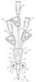
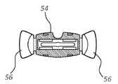
도 1에 도시되는 바와 같이, 봉합 날개부(22)의 봉합 홀(24)은, PCB(36)뿐만 아니라, 센서 어레이(30)의 센서(30, 34)에 전력을 제공하기 위한 전기 콘택을 포함하도록 구성된다. 특히, 환형 전기 콘택(40)은 허브 봉합 날개부(22)의 각각의 봉합 홀(24) 내에 포함되고, 전기 콘택은 PCB(36) 및 센서 어레이(30)에 동작 가능하게 연결된다. 도 4a 내지 도 4c에 도시되는 고정 디바이스(50)와 같은 고정 디바이스는 환자의 피부 상에 배치되도록 그리고, 카테터의 원위 부분이 환자 내로 삽입되는 후에, 카테터(10)와 동작 가능하게 연결되고 이를 제 위치에서 고정하도록 구성된다. 이를 위해서, 고정 디바이스(50)는 접착 패드에 장착되는 유지부(54), 및 허브를 제 위치에서 고정하기 위해서 (스냅-핏 배열로(in a snap-fit arrangement)) 허브(16)의 봉합 날개부(22) 위에서 제거 가능하게 피벗되도록 경첩식으로 연결되는 고정 아암을 포함한다.As shown in FIG. 1 , the sealing
고정 디바이스(50)는 센서 어레이(30) 및 PCB(36)에 전력을 제공하는 부가적인 기능을 포함할 수 있다. 구체적으로, 고정 디바이스(50)는 2개의 포스트(58)를 포함하고, 각각의 포스트는 전기 콘택(60)으로서의 역할을 하도록 구성되고, 각각의 포스트는, 고정 디바이스 내에 또한 포함되는, 배터리(62)와 동작 가능하게 연결된다. 봉합 홀의 전기 콘택(40)과 함께 전기 콘택이 형성되도록, 포스트(58)가 카테터 봉합 날개부(22)의 상응 봉합 홀(24) 내에 수용되도록 구성된다. 고정 디바이스(50)에 포함되는 배터리(62)는, 이러한 방식으로, 전력을 카테터 허브(16)의 센서(32, 34) 및 PCB(36)에 제공할 수 있다. 물론, 다른 외부 전원이 이용될 수 있다. 몇몇 실시형태에서, 카테터와 고정 디바이스 사이의 전기 콘택을 또한 이용하여 센서 데이터를 이들 사이에서 전달할 수 있다. 몇몇 다른 실시형태에서, 고정 디바이스는 카테터로부터 수신되는 센서 데이터를 송신하기 위한 라디오 또는 다른 모드를 포함할 수 있다. 또 다른 실시형태에서, PCB 또는 센서가 고정 디바이스에 포함될 수 있다. 고정 디바이스의 크기, 형상, 및 다른 구성이 본원에서 도시되고 설명되는 것으로부터 변경될 수 있다는 것을 이해할 수 있을 것이다.The fixed
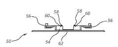
도 5a 내지 도 5c는 몇몇 실시형태에 따른 고정 디바이스(50)의 상세 부분을 도시하고, 고정 디바이스는, 예를 들어, 카테터(10)에 포함되는 센서 어레이(30)와 함께 사용하기 위한 배터리 및 PCB를 포함하는 포드(70)를 포함한다. 이는, PCB 또는 배터리를 카테터(10) 자체에 배치할 필요성을 제거한다. 도 5a 내지 도 5c는, 포드(70)가 유지부(54)의 상부 표면 상에서 전기 콘택(60)을 포함하는 것을 도시하고, 이는 카테터(10)의 허브(16) 상의 상응 전기 콘택과 전기적으로 연결되도록 구성된다. 따라서, 허브(16)가 고정 디바이스(50)의 고정 아암(56)에 의해서 제거 가능하게 유지될 때, 센서 어레이(30)는 포드(70)의 배터리 및 PCB에 의해서 전력을 공급 받고 통제된다. 포드(70)는 고정 디바이스(50)로부터 제거될 수 있게 구성되고, 그에 따라 포드는 연속되는 고정 디바이스들과 함께 재사용될 수 있다. 이는, 카테터(10) 또는 고정 디바이스(50)가 교환될 때, 도움이 될 수 있다. 따라서, PCB, 배터리, 또는 하나 이상의 센서 등을 포함하는, 포드(70)가 고정 디바이스로부터 제거될 수 있고 다른 곳에 배치될 수 있으며, 그에 따라 자원 및 비용을 절감할 수 있다. 배터리 및 PCB가 다른 위치 내에 또한 배치될 수 있다는 것에 또한 주목하여야 한다. 이러한 그리고 다른 변경이 그에 따라 고려된다. 본원에서 설명되는 것과 관련되는 카테터 고정 디바이스에 관한 추가적인 상세 내용을 ""Universal Catheter Anchoring System"라는 명칭의 미국 특허 제6,770,055호에서 확인할 수 있을 것이고, 이는 그 전체가 본원에서 참조로 포함된다.5A-5C show details of a
또한, 몇몇 실시형태에서, 고정 디바이스(50)는, 카테터(10)의 ECG 센서(34)와 협력할 수 있고, 그에 따라 이중 ECG 신호가 검출될 수 있게 하고 심장에 대한 카테터 관(12)의 원위 단부(13)의 근접도를 결정하기 위해서 사용될 수 있게 하는, ECG 센서(예를 들어, 전극)를 포함할 수 있다. 이러한 구성은 또한, 초기 카테터 배치 중 그리고 그 후의 환자 내의 카테터의 체류 중 모두에서, 카테터 관 원위 단부(13)의 위치 이상을 결정하기 위해서 사용될 수 있다. 압력 센서(32)로부터의 센서 데이터를 또한 ECG 신호와 함께 이용하여, 카테터 관의 원위 단부의 위치 이상을 추가적으로 검출할 수 있다.Also, in some embodiments, the
도 2 및 도 3은, 도 1의 단일-루멘 구성과 대조적인, 이중 및 삼중-루멘 카테터 구성을 각각 도시한다. 도 1의 것과 같이, 도 2 및 도 3에 도시되는 카테터(10)의 각각은, 상응 압력 센서(32), ECG 센서(34), 및 PCB(36)를 포함하여, 도 1에 도시되는 것과 유사한 센서 어레이(30)를 포함한다. 고정 디바이스(50)의 전기 콘택(60)(도 4a 내지 도 4c)과의 전기 연결을 위한 전기 콘택(40)이 또한 도시되어 있다. 압력 데이터가 각각의 연장 레그에서 감지될 수 있도록, 도 2 및 도 3의 카테터(10)의 각각의 연장 레그(18)가 압력 센서(32) 중 상응하는 하나를 포함한다는 것에 주목하여야 한다. 도 2 및 도 3에 도시되는 것보다 많거나 적은 센서(예: 젖산 센서, 산소 센서, 초음파 부품, GPS 위치 센서, 온도 센서, 루멘내 직경을 측정하기 위한 사이징 센서, 유체 속도 센서, 혈당 측정기, 산소 센서, 젖산 센서, 심박출량 센서, 가속도계, 혈액 용적(blood volumetric) 및 심박출량 센서 등)가 환자의 생리학적 양태 또는 카테터 조립체의 물리적 양태를 감지하기 위해서 이용될 수 있다.2 and 3 show double and triple-lumen catheter configurations, respectively, in contrast to the single-lumen configuration of FIG. 1 . 1 , each of the
도 6은 상응 연장 레그(18) 내의 특정 위치의 3개의 압력 센서(32) 및 하나의 연장 레그 내에 배치되는 ECG 센서(34)를 포함하는 카테터(10)를 도시하고, 각각의 센서는 허브(16) 내에 배치되는 PCB(36)에 동작 가능하게 연결된다. 그에 따라, 도 6은 센서(들) 및 PCB의 수, 유형, 및 배치가 이미 도시되고 설명되는 것과 다를 수 있다는 것을 나타낸다.6 shows a
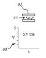
도 7은 몇몇 실시형태에 따른 센서-구비 카테터(10)의 상세 부분을 도시하고, 허브(16)는, 초음파 트랜스듀서(84A 및 84B)을 각각 제어하도록 구성되는 상부 및 하부 PCB(82A 및 82B)를 포함하는 초음파 조립체(80)를 포함한다. 초음파 트랜스듀서(84A 및 84B)는, 도 8a 내지 도 8d에 도시되는 바와 같이, 허브(16)의 유체 통로(26)를 초음파적으로 평가하여 루멘의 내용물을 결정하기 위해서 사용될 수 있다. 예를 들어, 도 8a의 초음파 신호 그래프(90)에 도시되는 바와 같이, 도 8a는, 공기가 유체 통로(26) 내에 존재할 때, 초음파 신호가 존재하지 않는다는 것을 보여준다. 대조적으로, 유체 A와 같은 유체가 유체 통로(26) 내에 존재할 때, 초음파 트랜스듀서(84A 및 84B)는, 도 8b의 그래프(90)에 의해서 확인되는 바와 같이, 유체 A의 조성과 일치되는 특정 전압의 신호를 복귀시킨다. 유체 A와 조성이 상이한 유체 B가 유체 통로(26) 내에 존재하는 경우에, 초음파 트랜스듀서(84A 및 84B)는, 도 8c의 그래프(90)에 의해서 확인되는 바와 같이, 유체 B의 조성과 일치되는 특정 전압의 신호를 복귀시킨다. 그리고 유체 및 공기 모두가 유체 통로(26) 내에 존재할 때, 도 8d의 그래프(90)는, 가변 전압 신호가 초음파 트랜스듀서(84A 및 84B)에 의해서 검출되는다는 것을 보여준다. 이러한 방식으로, 앞서서 더 설명되는 바와 같이 배터리 및 PCB와 커플링되는 초음파 트랜스듀서(84A 및 84B)는, 초음파 트랜스듀서의 배치에 따라, 허브(16)의 유체 통로(26) 내의 또는 다른 카테터 구성요소의 루멘 내의 특정 물질의 존재의 결정하는 데 있어서 사용자를 보조할 수 있다. 몇몇 다른 실시형태에서, 하나의 초음파 트랜스듀서만이 이용된다.7 shows a detail of a sensor-equipped
도 9a 및 도 9b는 몇몇 실시형태에 따른 센서-구비 카테터(10)의 상세 내용을 도시하고, 허브(16)는 그 내부에 배치되는 PCB(82)를 포함하고, 이러한 PCB(82)는 카테터의 루멘(14) 내에 존재하는 혈액 또는 다른 유체를 통해서 심부 체온을 측정하도록 배치되는, 열전쌍과 같은, 온도 센서(100)에 동작 가능하게 연결된다. 도 9b가 도시하는 바와 같이, 온도 센서(100)는 카테터 관(12) 또는 허브(16) 내에 길이방향으로 형성되는 스카이빙(skiving) 또는 공동(108)을 통해서 루멘(14)에 근접하여 배치될 수 있다. 온도 센서(100) 주위의 공동(108)을 충진하기 위해서, 포팅(potting)(106)이 선택적으로 이용될 수 있다. 온도 센서(100)(예를 들어, 서미스터)가 주입액(infusate)과 접촉하도록 구성되는 경우에, 온도 센서(100)는, 혈액 유량에 대해서 본원에서 설명되는 바와 같이, 그 유량을 측정하기 위해서 사용될 수 있다. 본원에 개시되는 압력 결정 수단과 함께 사용될 때, 더 정확한 폐색 결정이 이루어질 수 있다. 몇몇 실시형태에서, 온도 센서(100)는 미국 일리노이즈 버논 힐에 소재하는 Cole-Palmer Inc.로부터 입수할 수 있는 시리즈 400 Model 401 서미스터를 포함한다.9A and 9B show details of a sensor-equipped
도 10은, 다양한 센서가 센서 어레이(30)의 일부로서 허브(16) 또는 다른 적합한 위치에 포함될 수 있다는 것을 보여준다. 도 10에 도시되는 바와 같이, 허브(16)는 내부에 배치되는 압력 센서(32), (프로세서(36A) 및 무선 통신 모듈(36B)을 포함하는) PCB(36), 상부 및 하부 초음파 트랜스듀서(84A 및 84B), 온도 센서(100), 및 산소 센서(110)를 포함할 수 있다. 유체 통로 내에 존재하는 유체 내에서 검출되는 관련 매개변수를 감지하기 위해서, 여러 센서가, 필요에 따라, 허브(16)의 유체 통로(26)에 근접하여 배치된다. 센서의 특정 위치가 여기에 도시되는 것으로부터 변경될 수 있다.10 shows that various sensors may be included in
도 11은, 스마트폰(120)이, 전술한 몇몇 실시형태에서 설명한 바와 같이, 센서 어레이의 센서 중 하나 이상으로부터 데이터를 무선으로 수신하기 위한 수령 위치가 될 수 있다는 것을 보여준다. 데이터를 전송할 수 있는 무선 모드의 예에는 블루투스, Wi-Fi, 무선 주파수, 근거리 통신(NFC), ANT, ZigBee 등이 있다. 그러한 데이터 송신은 소프트웨어-기반의 애플리케이션 또는 다른 중간 디바이스를 통해서 중계될 수 있다. 이는, 임상의가, 환자의 진행 또는 상태를 모니터링할 수 있도록, 모바일 업데이트 및 다른 센서 데이터(124)를 스마트폰(120)의 디스플레이 화면(122)을 통해서(또는 소리, 진동 등을 포함하는 다른 매체에 의해서) 카테터(10)로부터 수신할 수 있게 한다. 전술한 바와 같은 센서 데이터의 수령을 위한 다른 위치는 환자 전자 의료 기록("EPR"), 환자 모니터링 장비, 전자 태블릿 및 랩탑 컴퓨터를 포함하는 다른 모바일 디바이스, 전자 저장 위치, 컴퓨터 서버, 간호사실, 카테터에 부착되는 펌프와 같은 의료 장비, 및 다양한 다른 목적지를 포함한다. 수령 위치에 배치되는 디바이스, 구성요소, 컴퓨터 등이, 분석, 추세, 경고 기능 등을 포함하는 동작을 수신 데이터에 대해서 수행할 수 있다는 것을 이해할 수 있을 것이다.11 shows that
도 12는 몇몇 실시형태에 따른 카테터(10)를 도시하고, 카테터는, 카테터 관(12)의 대부분이 환자의 맥관 구조 내에 배치되도록, 환자의 팔(128) 내로 삽입되어 도시되어 있다. 하나 이상의 센서를 포함하는 허브(16)가 또한, 연결 와이어(134)를 통해서 환자의 팔(128) 주위에 배치되는, 암밴드(130)와 같은, 보조 디바이스에 동작 가능하게 연결되어 도시되어 있다. 암밴드(130)는 몇몇 실시형태에서 카테터(10)의 외부 부분에 근접하여 배치되나, 이러한 위치 그리고 특정 형상, 크기, 구성, 및 본체 부착 체계가 다른 실시형태에서 달라질 수 있다. 도시되는 바와 같이, 암밴드(130)는, PCB(36) 및 (다른 실시형태에서 PCB에 포함되는) 무선 통신 모듈(136)을 포함하는, 연결 와이어(134)를 통해서 카테터(10)의 센서(들)와 협력하여 작업을 하는 여러 구성요소를 포함한다. 카테터(10)의 센서(들)에 의해서 검출되는 센서 데이터는 카테터(10)로부터 연결 와이어(134)를 통해서 암밴드(130)의 구성요소에 전달될 수 있고, 데이터는 (예를 들어, PCB(36)에 의해서) 프로세스될 수 있거나 (예를 들어, 무선 통신 모듈(136)을 통해서) 원격 위치로 송신될 수 있다. 몇몇 다른 실시형태에서, 카테터(10)와 암밴드(130) 사이의 동작 가능한 연결이 또한 무선 연결이다.12 illustrates a
PCB(36) 및 무선 통신 모듈(136)을 암밴드(130)에 배치하는 것은 카테터 상의 공간을 자유롭게 하고, 카테터(10) 자체가 새로운 카테터로 주기적으로 교체될 때 비교적 고가의 구성요소를 교체할 필요성을 방지할 수 있다. 그러한 경우에, 암밴드(130)는 새로운 카테터에 단순히 연결될 수 있고, PCB(36) 및 무선 통신 모듈(136)은, 이전의 카테터와 함께 하였던 것과 같이, 새로운 카테터와 함께 기능하기 시작할 수 있다. 카테터에 포함되는 센서(들)에 전력을 공급하기 위한 배터리, ECG 센서를 포함하는 부가적인 센서, 등을 포함하는, 다양한 다른 구성요소가 또한 암밴드(130)에 포함될 수 있다는 것에 주목하여야 한다. 언급한 바와 같이, 암밴드(130)는, 카테터(10)의 센서(들)에 동작 가능하게 연결되어 그 동작을 촉진할 수 있는 다른 웨어러블 및 비-웨어러블 보조 디바이스를 나타낸다. 암밴드/보조 디바이스에 포함되는 구성요소가 교체 가능/재사용 가능할 수 있다는 것에 주목하여야 한다. 몇몇 실시형태에서, PCB, 배터리, 또는 무선 통신 모듈이 카테터 고정 디바이스에 포함될 수 있다. 몇몇 다른 실시형태에서, 전술한 구성요소는, 암밴드에 제거 가능하게 부착될 수 있는 플랫폼 상에 포함될 수 있다. 몇몇 다른 실시형태에서, 암밴드 또는 유사 구성요소는, 이를 환자로부터 격리시키기 위한 또는 오염물질로부터의 격리를 제공하기 위한 일회용 차폐부를 포함한다.Placing the
전술한 실시형태 중 몇몇 실시형태는, 카테터(10)가 내부에 배치되는 환자의 중앙 정맥 압력과 관련되는 데이터를 감지하도록 구성되는 압력 센서(32)를 포함한다. 몇몇 다른 실시형태에서, 압력 센서(32)에 의해서 감지되는 데이터는, 피브린 피막(fibrin sheath) 또는 혈전과 같은 폐색이 카테터 관(12)의 루멘(14) 내에 존재할 수 있는 때를 검출하기 위해 추가로 사용될 수 있다. 도 13은, 예를 들어, 카테터 관 루멘(14)의 개방성(patency)을 유지하기 위해서 루어 연결부(20)에 연결되는 주사기를 이용하여 사용자에 의해서 카테터(10)를 통해서 유체가 플러싱되는 플러싱 절차 중에, 도 10의 압력 센서 구성에서와 같이, 압력 센서(32)에 의해서 감지되는 카테터 관 루멘(14) 내의 시간에 걸친 압력의 레벨을 도시하는 압력 곡선(142)을 포함하는 압력 그래프(140)를 도시한다. 도시되는 바와 같이, 압력 곡선(142)은, 부가적인 압력의 모멘트로 주사기를 펄싱하는(pulsing) 사용자에 의해서 유발되는 여러 압력 피크(144)를 포함한다. 이는, 카테터 관 루멘(14) 내에 또는 카테터 유체 경로의 다른 지역 내에 형성될 수 있는 임의의 사소한 장애물을 제거하기 위해서 수행될 수 있다. 페색이 카테터 관의 원위 단부(13)에 또는 루멘(14) 내에 존재할 때(예를 들어, 도 15의 폐색(178) 참조), 압력 곡선(142)이 상승되거나(즉, 압력 y-축을 따라서 수직 위쪽으로 이동되거나) 확장될(즉, 시간 x-축을 따라서 길어질) 것이다.Some of the foregoing embodiments include a
더 구체적으로, 유체의 유압 저항(R)은 일반적으로 이하의 관계식에 의해서 유체 유량(Q) 및 주입 압력(P)과 관련되며:More specifically, the hydraulic resistance (R) of a fluid is generally related to the fluid flow rate (Q) and injection pressure (P) by the following relation:
P = Q * R,(1)P = Q * R,(One)
이는 다음을 산출한다:This yields:

여기에서, V는 카테터(10) 내로 주입되는 유체의 알고 있는 부피이고, t1은 유체 주입 프로세스의 시작 시의 시간이고, t2는 유체 주입 프로세스의 종료 시의 시간이며(도 13 참조), P는 유체 주입 프로세스의 각각의 인스턴스 중의 순간적인 압력을 나타낸다는 것에 주목하여야 한다. (전술한 수학식을 이용하여) 특정 기간 동안 카테터 관(12)을 통한 유체 주입의 저항(R)을 비교하는 것 그리고 이를, 카테터(10)가 환자 내로 최초로 삽입되었고 폐색되지 않은 것 또는 개방되는 것으로 간주되었을 때와 같은, 이전 시간의 저항(R0)과 비교하는 것은 이하에 따라 카테터 관 내의 가능한 폐색의 백분율을 산출할 수 있다:where V is the known volume of fluid injected into the
% 폐색(occlusion) = R/R0(3)% occlusion = R/R0(3)
전술한 계산을 통하는 것과 같은, 압력 센서(32)에 의한 카테터 유체 경로 내의 상승 압력의 검출은 사용자에게 가능한 폐색을 경고할 수 있고, 그에 따라 교정 수단이 취해질 수 있다. 또한, PCB(36)를 가지는 카테터(10) 상에 위치되는 또는 환자 전자 의료 기록(또는 다른 원격 저장 위치) 내에 원격 위치되는 메모리 위치 내의 데이터 저장을 이용하여 시간에 걸친 카테터 플러싱 압력을 측정할 수 있고 그에 따라 시간에 걸친 압력 변화를 검출할 수 있다. 시간에 걸친 이러한 데이터 비교는, 이해될 수 있는 바와 같이, 카테터(10)에 위치되는 센서 중 임의의 하나에 대해서 수행될 수 있다. 물론, 센서에 의해서 감지되고 메모리 위치에 저장되는 데이터는, 이력 추세 등을 포함하는, 다양한 다른 용도를 위해서도 사용될 수 있다.Detection of elevated pressure in the catheter fluid path by the
도 14는, 원위 단부 유체 배출구(156)를 가지는 공동(154)을 형성하는 하우징(152)을 포함하는 압력-감지 주사기(150)의 다양한 상세 부분을 도시한다. 플런저(158)가 공동(154) 내에 배치되고 스프링(160)에 부착되며, 이러한 스프링은 초기에 압축 상태로 배치되고 주사기(150)의 근위 단부에 배치되는 해제 버튼(162)에 의해서 해제될 수 있다. 알고 있는 양의 0.9%의 일반적인 식염수(164) 또는 다른 적합한 액체가 플런저(158)에 대한 원위의 공동 내에 배치되고, 그에 따라 식염수는, 스프링(160)이 해제 버튼(162)에 의해서 작동될 때, 유체 배출구(156)를 빠져 나간다. 주사기가 상응 루어 연결부(20)에 동작 가능하게 부착될 때, 주사기(150)에 의해서 토출되는 식염수(164)는 연장 레그(18) 내로 (이어서, 허브(16) 및 카테터 관의 루멘(14)을 통해서) 주입된다.14 shows various details of a pressure-
압력 센서(166)가 유체 배출구(156)에 포함되어, 식염수가 유체 배출구(156)를 빠져 나가고 주사기(150)가 연결되는 카테터(10)에 진입할 때, 알고 있는 양의 식염수(164)의 압력을 측정한다. 프로세서 유닛(170) 및 디스플레이/제어 유닛(172)이 포함되어, 식염수(164)가 플런저(158)에 의해서 유체 배출구(156)를 통해서 토출될 때 존재하는 압력을 측정하고 (예를 들어, 더 앞에서 설명되는 수학식을 통해서) 계산한다. 프로세서 유닛(170)으로 추가적인 계산을 수행하여 주입의 유압 저항을 결정하고, 그에 따라, 부피를 알고 있는 주입되는 식염수(164), 압력 센서(166)에 의해서 측정되는 주입 압력, 및 모든 식염수의 주입을 달성하는 데 필요한 시간의 양을 이용하여, 카테터(10)의 유체 경로 내에 존재하는 폐색의 양을 산출한다. 몇몇 실시형태에서, 사용자는 디스플레이/제어 유닛(172)을 통해서 카테터 관 루멘(14)의 크기 및 그 길이를 입력할 수 있다.A
(예를 들어, 폐색되는 유체 경로의 %와 같은) 카테터 유체 경로 내에 존재하는 임의의 폐색의 양을 설명하는 결과가, 예를 들어, 디스플레이/제어 유닛(172) 상에서 표시될 수 있거나, 프로세서 유닛(170)과 함께 포함되는 무선 통신 모듈을 통해서 수령 위치로 무선 송신될 수 있다. 이어서, 필요한 경우에, 측정되는 교정을 사용자가 취할 수 있다.Results describing the amount of any occlusion present in the catheter fluid path (eg, such as % of fluid path occluded) may be displayed, eg, on display/
이력 압력/폐색 데이터가, 예를 들어, 디스플레이/제어 유닛(172)에 의한 호출 및 표시를 위해서, 프로세서 유닛(170)의 메모리 위치에 의해서 저장될 수 있다는 것에 주목하여야 한다. 몇몇 실시형태에서, 주사기(150)의 플런저(158)가 사용자에 의해서 수동으로 눌릴 수 있고, 그에 따라 스프링(160)의 필요성을 제거할 수 있고, 또는 플런저를 밀기 위한 가압 가스 공급원이 존재할 수 있고, 기타 등등이 이루어질 수 있다. 압력 센서(166)의 위치가 또한 본원에서 도시되고 설명되는 것으로부터 변경될 수 있다.It should be noted that the historical pressure/occlusion data may be stored by a memory location of the
몇몇 다른 실시형태에서, 압력 센서(32)를 이용하여, 적절한 배치에 대한 예상 값과 압력 센서에 의해서 검출되는 실제 감지 값 사이의 압력차를 감지하는 것에 의해서, 카테터 관(12)이 맥관 구조 내에서 잘못 배치되는 때를 결정할 수 있다는 것에 주목하여야 한다. 이러한 상황이 발생될 때, 위치 이상을 교정하기 위한 적절한 단계가 취해질 수 있다. 몇몇 다른 실시형태에서, 압력 센서(32) 및 전기(ECG) 센서(34)가 함께 작업하여, 정맥 압력 판독치 및 ECG 신호 분석을 기초로 카테터의 위치 이상을 검출할 수 있다.In some other embodiments, the
도 15는, 카테터 관(12)의 원위 단부(13)에 도시되는 부분적인 폐색(178)과 같은 폐색을 검출할 수 있는 능력을 가지는 카테터(10)의 여러 상세 부분을 도시한다. 도시되는 바와 같이, 카테터(10)는 카테터(10)의 루어 연결부(20)에 동작 가능하게 부착되는 압력 검출 모듈(180)을 포함한다. 주사기(182)가 압력 검출 모듈(180)의 근위 단부에 부착되어, 식염수 또는 다른 적합한 유체를 압력 검출 모듈(180)의 유동 루멘(184)을 통해서, 그리고 카테터(10)를 통한 유동을 위해 연장 레그(18) 내로 주입한다.FIG. 15 shows several details of the
도시되는 바와 같이, 압력 검출 모듈(180)은 유동 루멘(184)과 유체 연통되는 압력 표시부(188)를 포함한다. 압력 표시부(188)는, 압력 검출 모듈의 유동 루멘(184) 내에서 미리 결정되는 압력과 만날 때, 표시부 단편을 외측으로 연장시키도록 구성된다. 따라서, 주사기(182)(또는 다른 적합한 유체 주입 디바이스)에 의해서 시스템 내로 유체를 주입하는 동안 카테터 루멘(14) 내에서 미리 결정되는 압력을 초과하는 유체 압력을 만날 때, 압력 빌드업(pressure buildup)이 허브(16), 연장 레그(18), 및 유동 루멘(184)을 통해서 근위적으로 연장되어, 압력 표시부의 표시부 단편이 외측으로 연장되게 하고, 그에 따라 폐색이 존재할 수 있다는 것을 사용자에게 표시한다. 다른 구성의 표시부 단편들이 이용될 수 있다는 것을 이해할 수 있을 것이다. 압력 검출 모듈(180)은 카테터(10)에 부착될 수 있는 별도의 구성요소일 수 있고; 몇몇 다른 실시형태에서, 압력 검출 모듈은 카테터와 함께 일체로 형성된다.As shown, the
도 16은 카테터 관(12) 내의 센서 어레이(30)의 센서들을 위한 가능한 위치들을 도시한다. 도시되는 바와 같이, 센서 어레이(30)의 여러 센서(200)가, 다른 센서에 근접하여 배치되는 압력 센서(32)와 함께, 카테터 관(12)의 원위 단부(13)에 근접하여 배치된다. 도 16은, 센서 어레이(30)의 센서(200)에 전력을 공급하기 위해서, 연결 와이어(192)가, 예를 들어 루멘들(14)을 서로 분리하는 격막 내에서, 카테터 관의 중앙 부분을 따라서 연장되는 것을 더 도시한다. 몇몇 다른 실시형태에서, 연결 와이어(192)는 카테터 관의 길이를 연장시키는 전용 루멘 내에 배치될 수 있다. 여기에서 압력 센서(32)와 같은, 센서(들)를 카테터 관 원위 단부(13)에 근접한 거리에 배치하는 것은 카테터 관(12)이 원위적으로 트리밍될(trimmable) 수 있게 한다는 것에 주목하여야 한다.16 shows possible positions for the sensors of the
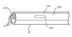
도 17은 카테터 관(12) 내에서 센서(202)를 포함하는 다른 구성을 도시하고, 여기에서 센서(202)는 벽 내에 길이방향으로 형성되는 스카이브 컷(skive cut)(198) 내에서 카테터 관(12)의 벽 내에 배치된다. 열 전도성 에폭시, 폴리우레탄 또는 RTV 포팅과 같은 포팅(204)이 센서(202)를 덮기 위해서 포함된다. 몇몇 실시형태에서, 센서(202)는 혈당 레벨을 감지하기 위한 혈당 센서를 포함하고, 혈당 센서가 혈액과 직접 접촉되도록, 둘러 싸이지(potted) 않는다. 이러한 그리고 다른 가능한 센서 위치가 그에 따라 고려된다.17 shows another configuration including a sensor 202 within a
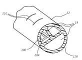
도 18은 카테터 관(12) 내에서 센서를 포함하는 다른 구성을 도시하고, 여기에서 센서(202)는 카테터 관(12)의 원위 단부(13)에 근접하여 카테터 관(12)의 루멘(14) 중 하나의 내부 표면 상에 또는 카테터 관(12) 내의 루멘 공간을 둘 이상의 루멘(14)으로 분할하는 격막 내에 배치된다. 필요에 따라 센서(202)를 절연시키고 덮기 위해서, 포팅(204)이 포함될 수 있다. 몇몇 실시형태에서, 포팅(204)은 열이 통과 전달될 수 있게 하면서 액체에 노출되지 않도록 센서(202)를 보호한다. 도 18은, 와이어-기반 전극(210)이, 그 외부 표면에서 노출되도록, 카테터 관(12)의 원위 단부(13)에 근접하여 카테터 관(12)의 벽 내에 배치될 수 있다는 것을 더 도시한다. 전극(210)은, 부피를 측정하여 카테터 관이 내부에 배치되는 용기의 크기를 결정하기 위해서, 그에 따라, 발생될 수 있는, 희망하지 않은 용기 내의 카테터 관의 위치 이상을 사용자가 결정하는 것을 보조하기 위해서 이용될 수 있는 동심적으로 배치되는 센서들로서 형성될 수 있다. 이러한 그리고 다른 가능한 센서 구성이 그에 따라 고려된다.18 shows another configuration comprising a sensor within the
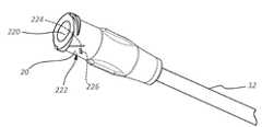
도 19는, 카테터 관(12)의 플러시 상태로 본원에서 또한 지칭되는, 유체를 이용한 카테터(10)의 바람직한 주기적 플러싱이 발생되는 때를 검출하기 위한 플러시 센서(222)의 여러 상세 부분을 도시한다. 도시되는 바와 같이, 플러시 센서(222)는 카테터 연장 레그(18)의 루어 연결부(20)의 공동(220) 내에 배치되나, 허브(16) 내와 같은 센서를 위한 다른 위치가 이용될 수 있고, 플러시 센서(222)는 선택적으로 서미스터이다. 본원에서 검출 모듈로도 지칭되는 플러시 센서(222)는 또한 도시되는 바와 같이 스프링(226)에 의해서 연장 위치로 편향되는 레버(224)를 포함한다. 플러시 센서(222)는, 그 동작의 통제 및 그 감지되는 데이터의 프로세스를 위해서, PCB(예를 들어, 도 10에 도시되는 PCB(36))의 프로세서 또는 (예를 들어, 루어 연결부(20) 내에 배치되는) 다른 적합한 구성요소에 동작 가능하게 연결된다.FIG. 19 shows several details of a
동작 시에, 식염수 또는 다른 적합한 유체로 카테터(10)를 플러싱하기 위해서 주사기 또는 다른 구성요소가 루어 연결부(20)의 공동(220) 내로 삽입될 때, 플러시 센서(222)의 레버(224)가 눌리고, 이는 플러싱 과정이 발생되는 것을 나타내는 신호가 프로세스에 전달되게 한다. 플러싱 시간 또는 플러싱 과정에 관한 다른 데이터가 프로세서에 의해서 기록, 저장 또는 사용될 수 있거나, 앞서서 더 설명되는 것과 유사한 방식으로 수령 위치로 무선으로 송신될 수 있다. 몇몇 실시형태에서, 플러시 센서(222) 및 PCB(36)의 프로세서가 플러시 센서 조립체로 지칭되나, 이러한 조립체가 부가적인 구성요소를 포함할 수 있다는 것을 이해할 수 있을 것이다. 몇몇 다른 실시형태에서, 전기 센서가 플러시 센서로서 이용될 수 있고, 전기 센서는, 구성요소가 연결부(20) 내로 삽입될 때마다 끊어지는 회로를 포함한다. 회로의 끊어짐이 타이머 회로를 리셋하여, 플러시 센서가 다시 활성화될 때까지 다음 기간을 측정할 수 있다.In operation, when a syringe or other component is inserted into the
몇몇 실시형태에서, 예를 들어, 카테터(10)가 12시간마다 적어도 1차례 플러싱되는 것이 바람직하다. 플러시 센서(222)가 전술한 바와 같은 플러싱 과정을 검출할 때, 프로세서 내의 타이머 회로가 리셋되어, 플러시 센서(222)가 다시 눌려 새로운 플러싱 과정을 표시할 때까지 다음 기간을 측정하기 위해서 시간을 카운트하기 시작한다.In some embodiments, for example, it is desirable for the
도 20은, 적색 LED 조명, 황색 LED 조명, 및 녹색 LED 조명의 집합체와 같은 조명 어레이(230)가 루어 연결부(20)의 표면에 포함되어 카테터(10)의 플러싱 상태를 시각적으로 표시할 수 있다는 것을 도시하고: 녹색 조명은 마지막 플러싱 과정이 검출되는 후에 10시간 미만이 경과되는 것을 나타내고; 황색 조명은 마지막 플러싱 과정 후에 10시간 초과 그러나 12시간 미만이 경과되는 것을 나타내며; 적색 조명은 마지막 플러싱 과정 후에 12시간 초과가 경과되는 것을 나타낸다. 프로세서는 조명 어레이의 동작을 통제하고, 조명의 숫자 크기, 위치, 목적, 표시 경과 시간 등이 달라질 수 있다는 것을 이해할 수 있을 것이다. 또한, 루어 연결부 공동(220) 내의 액체의 존재를 검출하는 센서를 포함하는, 다른 유형의 센서를 또한 이용하여 플러싱 과정을 검출할 수 있다는 것을 이해할 수 있을 것이다.20 shows that a
몇몇 다른 실시형태에서, 조명 어레이(230)가 다음과 같이 사용될 수 있다: 녹색 조명은 수용 가능한 플러싱 과정이 수행되는 후에 점멸되고; 적색 조명은 수용될 수 없거나 불완전한 플러싱 과정이 수행되는 후에 깜박이고; 황색 조명은 카테터 관(12) 내의 폐색의 존재 가능성을 표시하기 위해서 깜박이거나 켜진다. 몇몇 다른 실시형태에서, 황색 조명(또는 다른 조명)은 카테터(10)를 플러싱하라는 알림 역할을 위해서 켜질 수 있다.In some other embodiments, the
몇몇 다른 실시형태에서, 루어 연결부(20) 또는 카테터(10)의 다른 부분이 누름 버튼(또는 다른 사용자-활성화 구성요소)을 포함할 수 있고, 이러한 누름 버튼은 카테터 플러싱의 시간에 눌릴 수 있고, 그에 따라 타이머 회로를 리셋할 수 있다는 것을 이해할 수 있을 것이다. 이러한 경우에, 카운팅 회로가 또한 포함되어, 연결부(20) 또는 다른 구성요소에 접근한 횟수를 카운트할 수 있다.In some other embodiments, the
도 21은, 조명 어레이(230)가, 허브(16) 상의 배치를 포함하여, 카테터(10) 상의 다른 위치에 배치될 수 있다는 것을 보여준다. 예를 들어 카테터 관 또는 연장 레그, 또는 도 12의 암밴드(130)와 같은, 이러한 그리고 다른 가능한 위치가 그에 따라 고려된다. 몇몇 다른 실시형태에서, 조명 어레이를 이용하여, 상승되는 체온/열, 패혈증 발병(이하를 더 참조), 카테터 폐색, 낮은 혈중 산소 레벨 등을 포함하는 다른 감지되는 상태에 대해서 사용자에게 경고할 수 있다. 또한, 센서 데이터와 관련하여 사용자에게 경고하기 위해서, 조명에 더하여, 카테터 자체에서의 또는 데이터가 무선으로 송신되는 원격 수령 위치에서의 소리, 진동 등을 포함하는 다른 표시를 이용할 수 있다.21 shows that the
플러시 센서(222)가, 예를 들어 루어 연결부에 동작 가능하게 부착되도록 구성되는 무바늘 연결부를 포함하는, 다른 지역에 또한 포함될 수 있다는 것에 주목하여야 한다.It should be noted that
몇몇 실시형태에서, 압력 센서(32)를 (단독적으로 또는 전술한 플러시 센서(222)와 함께) 사용하여 플러싱 과정을 검출하거나 특성화할 수 있다. 예를 들어, 플러시 센서(222)는 플러싱 과정을 검출하기 위해서 사용될 수 있는 한편, 압력 센서(32)는 플러싱 과정 중에 존재하는 압력의 양을 감지할 수 있고, 그에 따라 발생 가능 폐색을 검출할 수 있다. 사실상, 몇몇 실시형태에서, 압력 센서(32)는, 예를 들어 PCB(36)에 포함되는 타이머 회로소자를 이용하여 시간의 함수로서 카테터의 루멘(14) 내의 압력을 측정함으로써, 카테터(10)의 플러싱 빈도수, 플러싱 기술, 플러싱 시간, 카테터 접근 횟수, 마지막 카테터 접근 이후에 경과되는 시간, 등을 결정하기 위해서 이용될 수 있다. 그러한 센서 데이터는, 설명한 바와 같이, 예를 들어 PCB(36)에 위치되는 메모리 위치에 의해서 저장될 수 있거나, 다른 국소적인 또는 원격의 수령 위치로 송신될 수 있다. 그러한 모니터링을 결정하기 위한 프로세싱이 PCB(36)에 포함되는 프로세서에 의해서 또는 원격으로 수행될 수 있다.In some embodiments, the pressure sensor 32 (alone or in combination with the
몇몇 실시형태에서, 압력 센서(32) 및 심부 체온 센서와 같은, 카테터 센서로부터의 센서 데이터를 이용하여 패혈증과 같은 환자 상태를 검출할 수 있다. 특히, 도 10에 도시되는 구성에서와 같이, 카테터(10)에 포함되는 압력 센서(32) 및 심부 체온 센서(100)를 통해서 혈액 유량, 호흡수, 심박수, 체온을 감지할 수 있다. 이러한 3개의 매개변수는, 패혈증의 시작을 결정하기 위해서 일반적으로 이용되는 4개의 매개변수 중 3개를 포함한다. 따라서, 본원에서 설명되는 바와 같이 카테터(10)를 통해서 이러한 매개변수를 모니터링하는 것을 이용하여 패혈증으로부터의 합병증을 검출하고 개선할 수 있다.In some embodiments, sensor data from catheter sensors, such as
도 22는 몇몇 실시형태에 따른 센서-기반의 카테터 조립체를 도시한다. 구체적으로, 카테터 관(12)이 환자의 맥관 구조 내에 배치되는 그리고 2개의 루어 연결부(20)가 카테터의 루멘에 유체를 제공하고 그로부터 유체를 제거하도록 구성되는 공급 라인(240)에 동작 가능하게 연결되는 상태로, 카테터(10)가 도시되어 있다. 펌프 유닛(250)이 포함되어 유체가 공급 라인(240)을 통해서 이동할 수 있게 한다. 필요한 경우 또는 희망하는 경우에, 식염수 유체 드립 조립체(252)가 또한 포함되어, 공급 라인을 통한 이동을 위해서 유체를 펌프 유닛에 제공할 수 있다. 주사기(182)와 같은 주사기가 포함되어, 공급 라인(240) 중 상응하는 하나 내에서 부가적인 유체 유입구를 제공한다.22 illustrates a sensor-based catheter assembly in accordance with some embodiments. Specifically, the
도 23은 도 22의 펌프 유닛(250)의 추가적인 상세 부분을 도시하고, 이는 혈액 또는 다른 유체를 환자 맥관 구조 내로부터 카테터(10)를 통해서(유체 유입구(256A)를 통해서) 펌프 유닛(250)으로 보내기 위해서 그리고 카테터를 통해서 유체를 (유체 배출구(256B)를 통해) 환자 맥관 구조로 복귀시키기 위해서 상응 공급 라인(240)(도 22)과 동작 가능하게 연결되도록 구성되는 유체 유입구(256A) 및 유체 배출구(256B)를 포함한다. 펌프(258)가 펌프 유닛(250)에 포함되어 유체를 이동시킬 수 있다. 또한, 다양한 입력 포트(260)가, 유체 유입구(256A)와 유체 연통되는 펌프 유닛(250)에 포함되어, 헤파린, 식염수, 동맥 주입물(arterial input) 등을 포함하는 부가적인 유체가 주입되게 할 수 있다.23 shows a further detail of the
하나 이상의 센서(262)가 또한 펌프 유닛(250) 내에 포함되고 배치되어, 환자 혈액의 하나 이상의 생리학적 양태를 측정할 수 있다. 그러한 센서의 예는 혈당 측정기, 산소 센서, 젖산 센서, 심박출량 센서 등을 포함한다. 센서(262)의 위치는 여기에 도시되는 것과 달리 변경될 수 있다. 카테터(10) 자체 상의 배치와 대조적으로, 센서(262)를 펌프 유닛(250) 내에 배치하는 것은, 카테터의 크기를 과도하게 증가시키지 않으면서, 비교적 큰 크기의 센서가 이용될 수 있게 한다.One or more sensors 262 may also be included and disposed within the
진단 시스템diagnostic system
도 24는 몇몇 실시형태에 따른 유선 또는 무선 통신을 위해서 구성되는 카테터 조립체(10) 및 콘솔(2402)을 포함하는 진단 시스템(2400)의 블록도를 제공한다. 도 25 및 도 26은 몇몇 실시형태에 따라 환자 상에서 사용되는 진단 시스템(2400)을 도시하고, 도 25의 진단 시스템은 유선 통신을 위해서 구성되고, 도 26의 진단 시스템은 무선 통신을 위해서 구성된다.24 provides a block diagram of a
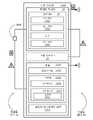
도시되는 바와 같이, 진단 시스템(2400)은 카테터 조립체(10), 콘솔(2402), 및 디스플레이 화면(2414)을 포함하고, 이들 중 카테터 조립체(10)는 1번-사용하는 일회용 장비인 반면, 콘솔(2402) 및 디스플레이 화면(2414)은 다수-사용하는 자본 장비이다. 디스플레이 화면(2414)이 도시되는 바와 같이 콘솔(2402) 내로 통합되는 통합형 디스플레이 화면일 수 있지만, 대안적으로, 디스플레이 화면(2414)은 진단 시스템(2400) 또는 그 콘솔(2402)과 양립될 수 있는 모니터의 별도의 디스플레이 화면일 수 있다. 이와 관계 없이, 디스플레이 화면(2414)은 콘솔(2402)과 통신하도록, 그리고 카테터 관(12)이 환자의 맥관 구조 내에 있는 동안 카테터 조립체(10)의 하나 이상의 센서(30)와 연관되는 온도 판독치를 적어도 하나 포함하는 GUI를 디스플레이하도록 구성된다.As shown, the
카테터 조립체(10)가, 콘솔(2402) 및 디스플레이 화면(2414)을 갖춘 진단 시스템(2400) 내에서 사용될 수 있는 관내 접근 디바이스의 예라는 것을 이해하여야 한다. 사실상, 그 대신, 관내 접근 디바이스가 캐뉼라 또는 바늘일 수 있다. 따라서, 개시 내용이 카테터 조립체(10)의 특징부에 대해서만 기재되는 때를 제외하고, 카테터 조립체(10)에 관한 개시 내용은 전술한 캐뉼라 또는 바늘과 같은 다른 관내 접근 디바이스를 포함하는 것으로 이해되어야 한다.It should be understood that
전술한 바와 같이, 카테터 조립체(10)는 카테터 관(12), 카테터 관(12)에 동작 가능하게 부착되는 허브(16), 허브(16)에 동작 가능하게 부착되는 하나 이상의 연장 레그(18)는 카테터 조립체(10)의 루멘 또는 유체 통로의 수, 및 하나의 온도 센서(예를 들어, 도 9a 또는 도 9b의 온도 센서(100)) 또는 복수의 온도 센서(예를 들어, 도 24에 도시되는 바와 같은 온도 센서(100a), 온도 센서(100b), …, 온도 센서(100n))와 같은 하나 이상의 센서(30)에 상응한다.As described above, the
관내 접근 디바이스가 캐뉼라 또는 바늘인 경우에, 캐뉼라 또는 바늘은 전술한 하나 이상의 센서(30)를 포함할 수 있다. 예를 들어, 이러한 관내 접근 디바이스는, 환자의 맥관 구조 내에 배치될 때 내부의 온도 측정을 위해서 구성되는 세장형 관의 원위-단부 부분 내에 배치되는 하나의 온도 센서를 가질 수 있다.Where the endoluminal access device is a cannula or needle, the cannula or needle may include one or
카테터 관(12)은 도 1에 도시되는 바와 같이 카테터 관(12)의 근위 단부와 원위 단부(13) 사이에서 연장되는 적어도 하나의 루멘을 형성한다. 허브(16)의 적어도 하나의 루멘 및 연장 레그(18)의 적어도 하나의 루멘과 함께, 카테터 관(12)의 적어도 하나의 루멘은 카테터 조립체(10)를 통해서 적어도 하나의 유체 통로를 형성한다. 카테터 조립체(10)는, 전술한 유체 통로만을 가지는 도 1의 모노루미날(monoluminal) 카테터 조립체(10)와 같은 모노루미날 카테터 조립체(10)일 수 있다. 대안적으로, 카테터 조립체(10)는 카테터 조립체(10)를 통한 2개의 유체 통로를 가지는 도 2의 디루미날(diluminal) 카테터 조립체(10) 또는 카테터 조립체(10)를 통한 3개의 유체 통로를 가지는 도 3의 트리루미날(triluminal) 카테터 조립체(10)와 같은 멀티루미날(multiluminal) 카테터 조립체일 수 있다.The
하나 이상의 센서(30)는 하나의 온도 센서(예를 들어, 도 9a 또는 도 9b의 온도 센서(100)) 또는 복수의 온도 센서(예를 들어, 도 24에 도시되는 바와 같은 온도 센서(100a), 온도 센서(100b), …, 온도 센서(100n))를 포함할 수 있다.The one or
카테터 조립체(10)가 하나의 온도 센서(100)를 가질 때, 하나의 온도 센서(100)는 내부의 온도 측정을 위해서 카테터 관(12), 허브(16), 또는 연장 레그(18) 내에 배치될 수 있다. 예를 들어, 도 9a, 도 9b 또는 도 17의 카테터 조립체(10)와 관련하여 전술한 바와 같이, 하나의 온도 센서(100)가 카테터 관(12)의 벽 내에 배치될 수 있다. 대안적으로, 하나의 온도 센서(100)는, 도 18의 카테터 조립체(10)와 관련하여 전술한 바와 같이, 카테터 관(12)의 격막 상에 또는 내에 배치될 수 있다. 하나의 온도 센서(100)를 고정 디바이스(50) 또는 콘솔(2402)과 같은 전원에 연결하기 위한 전기 리드가, 필요에 따라, 카테터 관(12)의 벽, 카테터 관(12)의 격막, 또는 카테터 관(12)의 벽 및 카테터 관(12)의 격막 모두 내에 배치될 수 있다.When the
카테터 조립체(10)가 복수의 온도 센서(100a, 100b, …, 100n)를 가질 때, 복수의 온도 센서(100a, 100b, …, 100n)는 내부의 온도 측정을 위해서 구성되는 카테터 관(12), 허브(16), 연장 레그(18), 또는 이들의 조합 내에 배치될 수 있다. 예를 들어, 카테터 관(12)은 카테터 관(12) 내의 온도를 측정하기 위해서 카테터 관(12) 내에 배치되는 적어도 하나의 온도 센서를 포함할 수 있고, 허브(16)는 허브(16) 내의 온도를 측정하기 위해서 허브(16) 내에 배치되는 적어도 하나의 온도 센서를 포함할 수 있고, 또는 카테터 관(12) 및 허브(16)의 카테터 조립체(50)의 각각의 구성요소가 온도 측정을 위해서 내부에 배치되는 적어도 하나의 온도 센서를 포함할 수 있다.When the
도 9a, 도 9b 또는 도 17의 카테터 조립체(10)와 관련하여 전술한 바와 같이, 복수의 온도 센서(100a, 100b, …, 100n)의 임의의 온도 센서와 같은 온도 센서가 카테터 관(12)의 벽 내에 배치될 수 있다. 대안적으로, 도 18의 카테터 조립체(10)와 관련하여 전술한 바와 같이, 복수의 온도 센서(100a, 100b, …, 100n)의 임의의 온도 센서와 같은 온도 센서가 카테터 관(12)의 격막 상에 또는 내에 배치될 수 있다. 카테터 관(12)의 벽 및 카테터 관(12)의 하나 이상의 격막 내의 복수의 온도 센서(100a, 100b, …, 100n)의 조합이 또한 가능하다. 복수의 온도 센서(100a, 100b, …, 100n)가 카테터 관(12)의 벽 내에, 카테터 관(12)의 격막 상에 또는 내에, 또는 이들의 조합으로 배치되든지 간에, 복수의 온도 센서(100a, 100b, …, 100n)는 카테터 관(12)의 길이를 따라서 간헐적으로 배치될 수 있다. 복수의 온도 센서(100a, 100b, …, 100n)의 각각의 온도 센서를 카테터 관(12)의 길이를 따라서 복수의 위치 중 상이한 위치에 배치하는 것은 상이한 위치들에서 국소적인 온도를 측정하는 데 있어서 유용하다. 복수의 온도 센서(100a, 100b, …, 100n)를 고정 디바이스(50) 또는 콘솔(2402)과 같은 전원에 연결하기 위한 전기 리드가, 필요에 따라, 카테터 관(12)의 벽, 카테터 관(12)의 격막, 또는 카테터 관(12)의 벽 및 카테터 관(12)의 격막 모두 내에 배치될 수 있다.As described above with respect to the
콘솔(2402)은 1차 메모리(2408) 및 2차 메모리(2410)와 같은 메모리(2406)를 포함한다. 1차 메모리(2408)는 랜덤-액세스 메모리("RAM")를 포함한다. 2차 메모리(2410)는, 카테터 관(12)이 환자의 맥관 구조 내에 배치되는 동안, 적어도, 하나 이상의 센서(30)로부터의 온도 데이터를 프로세싱하기 위한 하나 이상의 기능을 가지는 콘솔(2402)의 진단 프로세스를 예시하기 위해서 콘솔(2402)의 작동 시간에 1차 메모리(2408) 내로 로딩되는 설명서(2412)를 가지는 리드-온리 메모리("ROM")와 같은 비-휘발성 메모리를 포함한다. (환자의 맥관 구조 내에 배치되는 카테터 관(12)의 예에 대한 도 25 및 도 26 참조.) 설명서(2412)는 진단 프로세스, 진단 프로세스의 하나 이상의 기능, 온도 데이터를 프로세싱하기 위한 하나 이상의 알고리즘, 또는 이들의 조합을 위한 설명서를 포함할 수 있다. 설명서(2412)는 또한 콘솔(2402)에 대한 입력 및 콘솔(2402)로부터의 출력을 조정하도록 구성되는 디스플레이 서버를 예시하기 위한 것일 수 있다. 콘솔(2402)에 대한 입력은 예를 들어 디스플레이 화면(2414) 상의 GUI를 통해서 진단 프로세스의 하나 이상의 기능을 선택하는 것을 포함한다. 콘솔(2402)의 출력은 디스플레이 화면(2414) 상의 GUI를 포함한다.Console 2402 includes memory 2406 , such as
콘솔(2402)은 카테터 조립체(10) 및 디스플레이 화면(2414) 모두와 통신하도록, 그리고 고정 디바이스(50)가 사용되지 않을 때 카테터 조립체(10)에 전력을 공급하도록 구성된다. 그러한 통신 및 전력 옵션이 도 24 내지 도 26 사이에서 도시되어 있다. 예를 들어, 카테터 조립체(10)는 연결부(2416)를 통해서 콘솔(2402)에 유선 연결될 수 있고, 유선 연결은 전력이 콘솔(2402)로부터 카테터 조립체(10)로 제공될 수 있게 하고 데이터(예를 들어, 온도 데이터)가 카테터 조립체(10)로부터 콘솔(2402)로 제공될 수 있게 한다. (도 24 참조, 연결, 옵션 A.) 다른 예에서, 카테터 조립체(10)는 데이터(예를 들어, 온도 데이터)를 콘솔(2402)의 무선 통신 모듈에 제공하도록 구성되는 무선 통신 모듈을 가질 수 있다. 다시, 데이터 전달을 위해서 무선 통신이 이용되는 실시형태에서,카테터 조립체(10)에 대한 전력 공급은 고정 디바이스(50)에 의해서 제공될 수 있다. (도 24 참조, 연결, 옵션 B.)The console 2402 is configured to communicate with both the
온도 데이터를 프로세싱하기 위한 하나 이상의 알고리즘은, 카테터 관(12)이 환자의 맥관 구조 내에 배치되어 있는 동안 진단 프로세스로 카테터 조립체(50)의 임의의 온도 센서로부터의 온도 데이터를 프로세싱하는 데 유용하다. 예를 들어, 하나 이상의 온도 데이터-프로세싱 알고리즘은 환자의 맥관 구조 또는 피하 조직 내의 감염을 진단하기 위한 감염-진단 알고리즘을 포함할 수 있다. (다른 온도 데이터-프로세싱 알고리즘은 진단 프로세스의 특정 기능과 관련하여 이하에서 설명된다.) 카테터 조립체(50)가 카테터 관(12)의 길이를 따라 복수의 위치에 배치되는 복수의 온도 센서(100a, 100b, …, 100n)를 포함할 때, 감염-진단 알고리즘은, 카테터 관(12)의 길이를 따른 복수의 위치 중 임의의 하나 이상의 위치에서 환자의 맥관 구조 내의 감염을 진단하기 위해서, 진단 프로세스에 의해서 사용될 수 있다. 감염-진단 알고리즘으로 감염을 진단하는 것은, 복수의 위치 중 하나 이상의 위치에서 온도 센서 또는 온도 센서들에 의해서 각각 감지되는 국소적인 온도 변화 또는 그 경향에 따른다. 예를 들어, 감염은, 카테터 관(12)의 근위 단부에 위치되는 온도 센서에 의해서 제공되는 온도 데이터 사이의 온도 증가 경향에 의해서 삽입 부위에서 진단될 수 있다. 다른 예에서, 패혈증은 카테터 관(12)의 길이를 따른 복수의 온도 센서(100a, 100b, …, 100n) 중 몇 개의 온도 센서에 의해서 제공되는 온도 데이터 사이의 온도 증가 경향에 의해서 진단될 수 있다.One or more algorithms for processing the temperature data are useful for processing temperature data from any temperature sensor of the
진단 프로세스의 하나 이상의 기능들은 카테터 조립체(50)로부터 혈액이 채취되는 후에 플러싱 준수를 보장하기 위해서 플러싱-준수 기능을 포함할 수 있으며, 이는 이어서 카테터 조립체(50)의 개방성을 보장한다. 플러싱-준수 기능은, 플러싱-준수 온도 변화가 카테터 조립체(50)로부터 채취되는 환자-온도 혈액의 채취와 이어지는 상온 플러시액을 이용한 카테터 조립체(50)의 플러싱으로 인해서 예상되는 바와 같이 발생되지 않을 때, 또는 디바이스 개방성을 유지하기 위해서 카테터 조립체(50)를 플러싱하기 위한 권장 간격 마다(예를 들어, 12시간 마다), 콘솔(2402) 또는 디스플레이 화면(2414) 상의 시각적 경고 또는 콘솔(2402)에 의한 가청적 경고와 같은 경고를 제공하도록 구성된다. 전술한 바와 같이, 카테터 조립체(50)는 카테터 관(12) 내의 온도를 측정하기 위해서 카테터 관(12) 내에 배치되는 적어도 하나의 온도 센서, 허브(16) 내의 온도를 측정하기 위해서 허브(16) 내에 배치되는 적어도 하나의 온도 센서, 또는 내부의 온도 측정을 위해서 카테터 관(12) 및 허브(16)의 각각의 구성요소 내에 배치되는 적어도 하나의 온도 센서를 포함할 수 있다. 플러싱-준수 기능은, 플러싱-준수 온도 변화가 카테터 관(12)의 온도 센서, 허브(16)의 온도 센서, 또는 양 온도 센서에서, 예를 들어, 환자-온도 혈액이 카테터 조립체(50)로부터 채취되는 후에 카테터 조립체(50)를 통해서 플러싱되는 상온 플러시액으로부터 예상되는 바와 같이 발생되지 않을 때, 경고를 제공하도록 구성된다.One or more functions of the diagnostic process may include a flush-compliance function to ensure flush compliance after blood is drawn from the
진단 프로세스의 하나 이상의 기능이 혈액-유량 기능을 포함한다. 혈액-유량 기능에 따라, 진단 프로세스는, 카테터 관(12)의 원위-단부 부분 내에 또는 카테터 관(12)의 일부 다른 길이에 배치되는 특정 또는 1차 온도 센서에 관한 혈액 유량을 모니터링하기 위해서 혈액-유량 알고리즘을 이용한다. 1차 온도 센서는 콘솔(2402)의 PID 제어기에 통신 가능하게 커플링되고, 이러한 PID 제어기는 제어 신호를 제공하는 것에 의해서 혈액 온도보다 몇 도 높게 설정되는 온도에서 1차 온도 센서를 유지하도록 구성된다. 혈액 온도보다 몇 도 높게 설정되는 온도에서 1차 온도 센서를 유지하는 데 필요한 전력의 양이 혈액-유량 알고리즘에 의해서, 예를 들어 PID 제어기에 의해서 제공되는 제어 신호에 의해서 모니터링된다. 혈액 온도보다 몇 도 높게 설정되는 온도에서 1차 온도 센서를 유지하는 데 필요한 전력의 양이 혈액 유량에 비례하기 때문에, 진단 프로세스는 혈액-유량 알고리즘을 이용하여 1차 센서에 관한 혈액 유량을 결정할 수 있다. 혈액 유량을 이용하여, 카테터 관(12)(또는 이와 유사한 것)의 혈관 내의 초기 배치, 카테터 관(12)의 원위 단부(13)에서의 적절한 주입액 희석을 확인할 수 있다. 혈액 유량은 또한 카테터 이동 또는 혈관 폐색을 검출하기 위해서 이용될 수 있다. 또한, 혈액 유량은, 선택적으로, 감염-진단 알고리즘과 함께, 삽입 부위에서 감염을 진단하기 위해서 사용될 수 있다. 삽입 부위에서의 혈액 유량의 감소가 종종 감염으로 인한 부기(swelling)에 기인하기 때문에, 혈액-유량 알고리즘에 의한 측정되는 혈액 유량 감소는 감염의 표시자로서의 또는 감염-진단 알고리즘에 의한 감염 진단에 관한 체크로서의 역할을 할 수 있다.One or more functions of the diagnostic process include blood-flow functions. Depending on the blood-flow function, the diagnostic process is performed to monitor blood flow for a specific or primary temperature sensor disposed within the distal-end portion of the
관내 접근 디바이스가 캐뉼라 또는 바늘이고 세장형 관의 원위-단부 부분 내의 하나의 온도 센서가 1차 온도 센서일 때, 콘솔(2402)에 대한 입력은 혈액-유량 알고리즘으로부터 초래되는 혈액-유량 데이터로부터의 국소적인 최대치를 포함하고, 콘솔(2402)로부터 GUI로의 출력은 디스플레이 화면(2414) 상의 환자의 맥관 구조 내의 세장형 관의 원위-단부 부분의 성공적인 배치에 관한 표시를 포함한다.When the endoluminal access device is a cannula or needle and one temperature sensor in the distal-end portion of the elongate tube is the primary temperature sensor, the input to console 2402 is from blood-flow data resulting from the blood-flow algorithm. local maxima, and output from console 2402 to the GUI includes an indication on
진단 프로세스의 하나 이상의 기능이 심장-매개변수 기능을 포함한다. 심장-매개변수 기능에 따라, 진단 프로세스는, 심박수 및 심장 박출량을 포함하는 심장 매개변수를 결정하기 위해서 심장-매개변수 알고리즘과 조합하여 혈액-유량 알고리즘을 이용한다. 심박수는 혈액 유동 요동으로부터 측정될 수 있거나 온도 센서 이외의 다른 센서로부터 입력될 수 있다.One or more functions of the diagnostic process include cardiac-parameter functions. Depending on the cardiac-parameter function, the diagnostic process uses the blood-flow algorithm in combination with the cardiac-parameter algorithm to determine cardiac parameters including heart rate and cardiac output. The heart rate may be measured from blood flow fluctuations or may be input from a sensor other than a temperature sensor.
예를 들어, 심박수는 ECG 스타일렛 또는 ECG 센서(34)를 통해서 측정될 수 있다.For example, the heart rate may be measured via an ECG stylet or
진단 프로세스의 하나 이상의 기능이 카테터-추적 기능을 포함한다. 카테터-추적 기능에 따라, 진단 프로세스는, 1차 온도 센서가 혈액 유동의 용적 증가에 따라 관내 접합부를 지나서 전진하는 때를 결정하기 위해서, 카테터-추적 알고리즘과 조합하여 혈액-유량 알고리즘을 이용한다. 전술한 것에 따라 초래되는 혈액 유동 및 혈액 유동의 변화가 카테터-추적 데이터로서 추적될 수 있고, 진단 프로세스가 이를 이용하여 혈액 유동의 추세를 결정할 수 있다. 진단 프로세스는, 디스플레이 화면의 GUI에 대한 출력을 위해서, 카테터-추적 데이터 또는 그로부터 결정되는 추세를 입력으로서 디스플레이 서버에 제공하도록 구성된다. GUI에 대한 출력은 임상의에게 환자의 맥관 구조 내의 카테터 관(12)의 위치에 관한 표시를 제공한다.One or more functions of the diagnostic process include catheter-tracking functions. In accordance with the catheter-tracking function, the diagnostic process uses a blood-flow algorithm in combination with the catheter-tracking algorithm to determine when the primary temperature sensor is advanced past the endoluminal junction as the volume of blood flow increases. Blood flow and changes in blood flow resulting from the foregoing can be tracked as catheter-tracking data, which the diagnostic process can use to determine trends in blood flow. The diagnostic process is configured to provide the catheter-tracking data or a trend determined therefrom to the display server as input for output to the GUI of the display screen. The output to the GUI provides the clinician with an indication regarding the location of the
또한, 카테터-추적 기능에 따라, 진단 프로세스는, 전술한 1차 온도 센서에 근접하여 카테터 관(12) 내에 배치되는 2차 온도 센서로부터의 온도 데이터에 따라 환자의 맥관 구조 내의 카테터 관(12)의 위치 이상을 결정하도록 구성될 수 있다. 2차 온도 센서로부터의 온도 데이터는, 카테터 관(12)이 혈액 유동에 대항하여 이동 또는 배향될 때, 환자의 혈액 온도를 나타낸다. 2차 온도 센서로부터의 온도 데이터는, 혈액 온도보다 몇 도 높게 설정되는 온도의 1차 온도 센서를 고려할 때, 카테터 관(12)이 혈액 유동과 함께 이동할 때 상승되는 혈액 온도를 나타낸다. 혈액 온도 또는 상승되는 혈액 온도와 관련되는 정보는 디스플레이 화면의 GUI로의 출력을 위해서 디스플레이 서버에 단속적인 또는 연속적인 입력으로서 제공될 수 있다. GUI에 대한 출력은 임상의에게 환자의 맥관 구조 내의 카테터 관(12)의 위치 이상에 관한 표시를 제공한다.In addition, in accordance with the catheter-tracking function, the diagnostic process is performed in accordance with temperature data from a secondary temperature sensor disposed within the
전술한 내용에도 불구하고, 카테터 관(12)의 위치 이상은 또한 혈액-유량 알고리즘에 의해서 1차 센서 주위의 혈액 유량의 변화에 의해서 결정될 수 있다.Notwithstanding the foregoing, anomalies in the position of the
진단 프로세스의 하나 이상의 기능들은 ECG 데이터를 프로세싱하기 위한 ECG 기능을 포함할 수 있다. 전술한 바와 같이, 카테터 조립체(50)는 ECG 센서(34)를 포함할 수 있다. 대안적으로, 진단 시스템은 카테터 관(12) 내에 배치되도록 구성되는 심전도("ECG") 스타일렛을 추가로 포함한다. ECG 기능은, ECG 센서(34) 또는 ECG 스타일렛이 내부에 배치되는 카테터 관(12)이 환자의 맥관 구조 내에 배치되어 있는 동안, ECG 센서(34) 또는 ECG 스타일렛으로부터의 ECG 데이터를 프로세싱하기 위한 것이다. ECG 기능은 카테터 관(12)의 원위 단부(13) 또는 선단부의 위치를 확인하고, 카테터 관(12)의 선단부의 이동을 모니터링하고, 심박수를 결정하고, 또는 이들의 조합을 수행한다. 진단 프로세스의 ECG 기능을 이용하여, 카테터-관 배치 중의 카테터-선단부 위치를 확인할 수 있고, 카테터-선단부 이동을 모니터링할 수 있고, 또는 진단 프로세스의 심장-매개변수 기능을 위해서 심박수를 측정할 수 있다.One or more functions of the diagnostic process may include an ECG function for processing ECG data. As noted above, the
진단 프로세스의 여러 기능을 함께 이용하여, 환자 모니터링을 위한 임상적 데이터를 제공할 수 있다. 이는, 진단 시스템(2400)이 주입 시스템 또는 환자 모니터링 시스템에 커플링될 때, 특히 유용하다. 예를 들어, 주입 시스템과 관련하여, 진단 시스템(2400)은 약물의 주입에 반응하는 환자에 대한 약물-주입 데이터와의 상관 관계에 대한 임상적 데이터를 제공하도록 구성될 수 있다. 온도, 혈액 유량 및 심박출량 데이터는 이후에 약물-주입 속도에 대한 데이터와 함께 추세화될 수 있고, 전술한 데이터는 전자 의료 기록 또는 환자 데이터 데이터베이스에 업로드될 수 있으며, 이어서 데이터를 인공-지능 알고리즘과 함께 사용하여 환자 간호를 개선할 수 있다.The multiple functions of the diagnostic process can be used together to provide clinical data for patient monitoring. This is particularly useful when the
방법Way
진단 시스템(2400)의 방법은, 콘솔(2402)의 메모리(2406)(예를 들어, 1차 메모리(2408)) 내에서, 적어도 온도 데이터를 프로세싱하기 위한 하나 이상의 기능을 가지는 진단 프로세스를 예시하는 예시 단계를 포함한다.The method of the
방법은 또한 온도 센서(100) 또는 복수의 온도 센서(100a, 100b, …, 100n) 중 임의의 온도 센서로부터의 온도 데이터를 카테터 조립체(50)로부터 콘솔(2402)로 전송하는 전송 단계를 포함한다. 방법은 또한 온도 데이터를 메모리(2406)(예를 들어, 1차 메모리(2408))에 로딩하는 로딩 단계를 포함한다. 방법은 또한 온도 데이터를 프로세싱하기 위한 하나 이상의 기능에 따라 콘솔(2402)의 프로세서(2404)로 온도 데이터를 프로세싱하는 프로세싱 단계를 포함한다.The method also includes transmitting temperature data from the
방법은 또한, 환자의 맥관 구조 내에 배치되어 있는 동안, 적어도, 카테터 조립체(50)의 임의의 온도 센서와 연관되는 온도 판독치를, 콘솔(2402)과 통신하도록 구성되는 디스플레이 화면(2414) 상의 GUI 내에서 디스플레이하는 디스플레이 단계를 포함한다.The method also includes at least within a GUI on a
방법은 또한 혈액-유량 알고리즘을 이용하는 혈액-유량 기능으로 환자의 맥관 구조 내에 배치되는 카테터 조립체(50)의 임의의 온도 센서에 관한 혈액 유량을 모니터링하는 모니터링 단계를 포함할 수 있다. 다시, 혈액 유량은 혈액 온도보다 몇 도 높게 설정되는 온도에서 온도-센서를 유지하는 데 필요한 전력의 양에 비례한다.The method may also include a monitoring step of monitoring the blood flow rate for any temperature sensor of the
본원에 개시되는 진단 시스템 및 방법은 센서(들)를 관내 접근 디바이스 내에 통합하는 것에 의해서 가치 있는 임상적 데이터를 임상의에게 제공한다. 이는 추가적인 관내 디바이스를 환자 내에 배치할 필요성을 제거하고, 환자 감염 및 다른 합병증의 위험을 줄인다. 또한, 본원에 개시되는 진단 시스템은, 혈관 디바이스 주변의 혈액 유동의 품질, 플러싱 프로토콜의 준수 모니터링, 및 혈관 접합부에 대한 관내 디바이스의 위치의 모니터링과 같은, 이미 시장에 있는 추가적인 관내 디바이스에 현재 존재하지 않는 부가적인 데이터 및 특징을 제공한다.The diagnostic systems and methods disclosed herein provide clinicians with valuable clinical data by incorporating the sensor(s) into an intraluminal access device. This eliminates the need to place an additional endoluminal device within the patient and reduces the risk of patient infection and other complications. In addition, the diagnostic system disclosed herein does not currently exist in additional endoluminal devices already on the market, such as monitoring the quality of blood flow around the vascular device, monitoring compliance with flushing protocols, and monitoring the position of the endoluminal device relative to the vascular junction. It provides additional data and features that are not
일부 특정 실시형태를 본원에 개시하였고 특정 실시형태를 일부 상세 내용으로 개시하였지만, 그러한 특정 실시형태는 본원에서 제공되는 개념의 범위를 제한하기 위한 것은 아니다. 부가적인 구성 또는 수정이 당업자에게 명확할 수 있고, 더 넓은 양태에서, 이러한 구성 또는 수정이 또한 포함된다. 따라서, 본원에서 제공되는 개념의 범위를 벗어나지 않고도, 본원에 개시되는 특정 실시형태로부터 벗어날 수 있다.While some specific embodiments have been disclosed herein and specific embodiments have been disclosed in some detail, such specific embodiments are not intended to limit the scope of the concepts provided herein. Additional configurations or modifications may be apparent to those skilled in the art, and in a broader aspect, such configurations or modifications are also included. Accordingly, departures may be made from the specific embodiments disclosed herein without departing from the scope of the concepts provided herein.
Claims (20)
Translated fromKorean카테터 조립체 - 상기 카테터 조립체는, 근위 단부와 원위 단부 사이에서 연장되는 적어도 하나의 루멘(lumen)을 형성하는 카테터 관; 상기 카테터 관에 동작 가능하게 부착되는 허브; 상기 허브에 동작 가능하게 부착되는 연장 레그; 및 상기 카테터 관, 상기 허브, 또는 상기 연장 레그 내에 배치되는 하나의 온도 센서, 또는 상기 카테터 관, 상기 허브, 또는 상기 연장 레그 내에 배치되는 복수의 온도 센서, 또는 온도를 측정하도록 구성되는 이들의 조합을 포함하고, 상기 허브 및 상기 연장 레그는 상기 카테터 관의 루멘과 유체 연통되는(in fluid communication with) 적어도 하나의 유체 통로를 형성함(define) - ;
상기 카테터 조립체와 통신하도록 구성되는 콘솔 - 상기 콘솔은 메모리 및 프로세서를 포함하고, 상기 프로세서는, 상기 카테터 관이 환자의 맥관 구조 내에 배치되어 있는 동안, 적어도 온도 데이터를 프로세싱하기 위한 하나 이상의 기능을 가지는 진단 프로세스를 예시하도록 구성됨 - ; 및
상기 콘솔과 통신하도록 구성되는 디스플레이 화면으로서, 상기 하나 이상의 센서와 연관되는 온도 판독치를 적어도 하나 포함하는 그래픽 사용자 인터페이스(graphical user interface, "GUI")를 디스플레이하도록 구성되는, 디스플레이 화면;
을 포함하는,
진단 시스템.
A diagnostic system comprising:
Catheter assembly - The catheter assembly comprising: a catheter tube defining at least one lumen extending between a proximal end and a distal end; a hub operatively attached to the catheter tube; an extension leg operatively attached to the hub; and one temperature sensor disposed within the catheter tube, the hub, or the extended leg, or a plurality of temperature sensors disposed within the catheter tube, the hub, or the extended leg, or a combination thereof configured to measure temperature. wherein the hub and the elongate leg define at least one fluid passageway in fluid communication with a lumen of the catheter tube;
a console configured to communicate with the catheter assembly, the console comprising a memory and a processor, the processor having one or more functions for processing at least temperature data while the catheter tube is placed in a vasculature of a patient configured to exemplify a diagnostic process; and
a display screen configured to communicate with the console, the display screen configured to display a graphical user interface (“GUI”) comprising at least one temperature reading associated with the one or more sensors;
containing,
diagnostic system.
상기 콘솔은, 상기 콘솔에 대한 입력 및 상기 콘솔로부터의 출력을 조정하도록 구성되는 디스플레이 서버를 예시하도록 구성되고,
상기 입력은, 상기 진단 프로세스의 하나 이상의 기능들의 선택을 포함하고, 그리고 상기 출력은 GUI를 포함하는,
진단 시스템.
According to claim 1,
the console is configured to illustrate a display server configured to coordinate input to and output from the console;
wherein the input comprises selection of one or more functions of the diagnostic process, and the output comprises a GUI.
diagnostic system.
상기 메모리는,
상기 카테터 관이 환자의 맥관 구조(vasculature) 내에 배치되어 있는 동안, 상기 진단 프로세스로 상기 카테터 조립체의 온도 센서로부터의 상기 온도 데이터를 프로세싱하기(process) 위한 하나 이상의 온도 데이터-프로세싱 알고리즘들을 포함하는,
진단 시스템.
According to claim 1,
The memory is
one or more temperature data-processing algorithms for processing the temperature data from a temperature sensor of the catheter assembly into the diagnostic process while the catheter tube is placed within a vasculature of a patient.
diagnostic system.
상기 카테터 관은 복수의 온도 센서들을 포함하고,
상기 복수의 온도 센서들의 온도 센서 각각은, 국소적인 온도(local temperature)를 측정하기 위해서 상기 카테터 관의 길이에 따른(along) 복수의 위치들 중 상이한 위치에 배치되는,
진단 시스템.
4. The method according to any one of claims 1 to 3,
The catheter tube comprises a plurality of temperature sensors,
wherein each temperature sensor of the plurality of temperature sensors is disposed at a different one of a plurality of locations along the length of the catheter tube to measure a local temperature;
diagnostic system.
상기 메모리는,
상기 복수의 위치들 중 하나 이상의 위치들에서 상기 온도 센서 또는 상기 온도 센서들 각각의 국소적인 온도 변화들 또는 그 추세(trend)들에 따라 상기 카테터 관의 길이에 따른 복수의 위치들 중 하나 이상의 위치들에서 상기 진단 프로세스로 상기 환자의 맥관 구조 또는 피하 조직(subcutaneous tissue) 내의 감염을 진단하기 위한 감염-진단 알고리즘을 포함하는,
진단 시스템.
5. The method of claim 4,
The memory is
one or more of the plurality of locations along the length of the catheter tube according to local temperature changes or trends of the temperature sensor or each of the temperature sensors at one or more of the plurality of locations an infection-diagnostic algorithm for diagnosing an infection in the vasculature or subcutaneous tissue of the patient with the diagnostic process in
diagnostic system.
상기 카테터 관은,
상기 카테터 관 내에 배치되는 적어도 하나의 카테터-관 온도 센서, 상기 허브 내에 배치되는 적어도 하나의 허브 온도 센서, 또는 이들의 조합을 포함하고, 그리고
상기 조합은, 상기 카테터 관, 상기 허브 또는 상기 카테터 관 및 상기 허브 둘 다에 대한 온도 측정을 위해 구성되는,
진단 시스템.
4. The method according to any one of claims 1 to 3,
The catheter tube,
at least one catheter-tube temperature sensor disposed within the catheter tube, at least one hub temperature sensor disposed within the hub, or a combination thereof, and
wherein the combination is configured for temperature measurement for the catheter tube, the hub, or both the catheter tube and the hub.
diagnostic system.
상기 진단 프로세스의 하나 이상의 기능들은,
환자-온도 혈액이 상기 카테터 조립체로부터 채취되는 후에, 또는 권장 간격(interval)들 또는 인스턴스(instance)들에서 상기 카테터 조립체를 통해 플러시(flush)되는 상온 플러시액(room-temperature flushate)으로부터 예상되는 바와 같이, 플러싱-준수 온도 변화(flushing-compliant temperature change)가 상기 카테터-관 온도 센서, 상기 허브 온도 센서, 또는 상기 카테터-관 온도 센서 및 상기 허브 온도 센서 둘 다에서 발생(occur)되지 않을 경우, 콘솔-기반 경고를 제공하도록 구성되는 플러싱-준수 기능을 포함하는,
진단 시스템.
7. The method of claim 6,
One or more functions of the diagnostic process include:
After patient-temperature blood is drawn from the catheter assembly, or as expected from a room-temperature flushate flushed through the catheter assembly at recommended intervals or instances. Likewise, if a flushing-compliant temperature change does not occur at the catheter-tube temperature sensor, the hub temperature sensor, or both the catheter-tube temperature sensor and the hub temperature sensor, comprising a flush-compliant function configured to provide console-based alerts;
diagnostic system.
상기 카테터 관은, 상기 카테터 관 내에 배치되는 1차 카테터-관 온도 센서를 포함하고,
상기 콘솔은, 상기 1차 카테터-관 온도 센서를 혈액 온도보다 높게 설정되는 온도에서 유지하도록 구성되는 1차 카테터-관 온도 센서에 통신 가능하게 커플링(couple) 되는 비례-적분-미분(proportional-integral-derivative, "PID") 제어기를 포함하는,
진단 시스템.
4. The method according to any one of claims 1 to 3,
The catheter tube comprises a primary catheter-tube temperature sensor disposed within the catheter tube,
wherein the console is communicatively coupled to a primary catheter-tube temperature sensor configured to maintain the primary catheter-tube temperature sensor at a temperature that is set above a blood temperature. integral-derivative, "PID") controller, comprising
diagnostic system.
상기 진단 프로세스의 하나 이상의 기능들은,
상기 진단 프로세스가 혈액-유량 알고리즘을 이용하여 혈액 온도보다 높게 설정되는 온도에서 상기 1차 카테터-관 온도 센서를 유지하는 데 필요한 전력의 양을 통해서 상기 1차 카테터-관 온도 센서 주위의 혈액 유량을 모니터링하는, 혈액-유량 기능을 포함하고,
상기 혈액 유량은 혈액 온도보다 높게 설정되는 온도에서 상기 1차 카테터-관 온도 센서를 유지하는 데 필요한 전력의 양에 비례하는,
진단 시스템.
9. The method of claim 8,
One or more functions of the diagnostic process include:
The diagnostic process determines the blood flow rate around the primary catheter-tube temperature sensor through the amount of power required to maintain the primary catheter-tube temperature sensor at a temperature that is set above the blood temperature using a blood-flow algorithm. monitoring, comprising a blood-flow function,
wherein the blood flow rate is proportional to the amount of power required to maintain the primary catheter-tube temperature sensor at a temperature set above the blood temperature.
diagnostic system.
상기 진단 프로세스의 하나 이상의 기능들은,
상기 진단 프로세스가 심장 박출량(cardiac stroke volume)을 포함하는 심장 매개변수를 결정하기 위해 심장-매개변수 알고리즘과 조합하여 상기 혈액-유량 알고리즘을 이용하는, 심장-매개변수 기능을 포함하는,
진단 시스템.
10. The method of claim 9,
One or more functions of the diagnostic process include:
wherein the diagnostic process uses the blood-flow algorithm in combination with a cardiac-parameter algorithm to determine cardiac parameters including cardiac stroke volume.
diagnostic system.
상기 진단 프로세스의 하나 이상의 기능들은,
상기 진단 프로세스가, 상기 1차 카테터-관 온도 센서가 혈액 유동의 용적 증가(volumetric increase)에 따라 관내 접합부를 지나서 전진하는 경우를 결정하기 위해서, 카테터-추적 알고리즘과 조합하여 상기 혈액-유량 알고리즘을 이용하는, 카테터-추적 기능을 포함하는,
진단 시스템.
10. The method of claim 9,
One or more functions of the diagnostic process include:
The diagnostic process uses the blood-flow algorithm in combination with a catheter-tracking algorithm to determine when the primary catheter-tube temperature sensor is advancing past the endoluminal junction with a volumetric increase in blood flow. using a catheter-tracking function, comprising:
diagnostic system.
상기 진단 프로세스는 상기 카테터-추적 알고리즘으로부터 초래되는(result from) 카테터-추적 데이터를 상기 디스플레이 화면의 상기 GUI에 대한 디스플레이-서버 출력을 위한 디스플레이-서버 입력으로 제공하도록 구성되고,
상기 GUI에 대한 상기 디스플레이-서버 출력은 임상의에게 상기 환자의 맥관 구조 내의 상기 카테터 관의 위치에 관한 표시를 제공하는,
진단 시스템.
12. The method of claim 11,
wherein the diagnostic process is configured to provide catheter-tracking data resulting from the catheter-tracking algorithm as a display-server input for display-server output to the GUI of the display screen;
wherein the display-server output to the GUI provides an indication to the clinician regarding the location of the catheter tube within the patient's vasculature.
diagnostic system.
상기 카테터 관은,
상기 환자의 맥관 구조 내의 상기 카테터 관의 위치 이상(malposition)을 결정하기 위해 상기 1차 카테터-관 온도 센서에 근접하여 상기 카테터 관 내에 배치되는 2차 카테터-관 온도 센서;
를 포함하는,
진단 시스템.
12. The method of claim 11,
The catheter tube,
a secondary catheter-tube temperature sensor disposed within the catheter tube proximate to the primary catheter-tube temperature sensor to determine a malposition of the catheter tube within the vasculature of the patient;
containing,
diagnostic system.
상기 카테터-추적 기능은, 상기 2차 카테터-관 온도 센서로부터의 상기 온도 데이터에 따라 상기 카테터의 위치 이상을 결정하도록 구성되고,
상기 2차 카테터-관 온도 센서로부터의 상기 온도 데이터는, 상기 혈액 온도보다 높게 설정되는 온도의 상기 1차 카테터-관 온도 센서로 인해(on account of) 상기 카테터 관이 혈액 유동에 따라 이동하는 경우의 상승되는 혈액 온도 또는 상기 카테터 관이 상기 혈액 유동에 대향하여 이동하는 경우의 상기 환자의 상기 혈액 온도를 나타내는,
진단 시스템.
14. The method of claim 13,
wherein the catheter-tracking function is configured to determine an anomaly of the position of the catheter according to the temperature data from the secondary catheter-tube temperature sensor;
The temperature data from the secondary catheter-tube temperature sensor is determined when the catheter tube moves with blood flow due to the primary catheter-tube temperature sensor at a temperature set higher than the blood temperature. representing the elevated blood temperature of or the patient's blood temperature when the catheter tube is moved against the blood flow;
diagnostic system.
상기 카테터 조립체 내에 내재되는 심전도(electrocardiogram, "ECG") 스타일렛(stylet) 또는 리드(lead)들;
을 더 포함하고, 그리고
상기 진단 프로세스의 하나 이상의 기능들은,
상기 카테터 관의 선단부(tip)의 위치를 확인하기 위해서, 상기 카테터 관의 선단부의 이동을 모니터링하기 위해서, 심박수를 결정하기 위해서 또는 이들의 조합을 위해서, 상기 ECG 스타일렛이 상기 카테터 관 내에 배치되고 상기 카테터 관이 환자의 맥관 구조 내에 배치되는 동안, ECG 데이터를 프로세싱하기 위한 ECG 기능을 포함하는,
진단 시스템.
4. The method according to any one of claims 1 to 3,
an electrocardiogram (“ECG”) stylet or leads embedded within the catheter assembly;
further comprising, and
One or more functions of the diagnostic process include:
The ECG stylet is disposed within the catheter tube to determine the position of the tip of the catheter tube, to monitor movement of the tip of the catheter tube, to determine heart rate, or a combination thereof. an ECG function for processing ECG data while the catheter tube is placed within a vasculature of a patient;
diagnostic system.
관내 접근 디바이스 - 상기 관내 접근 디바이스는, 근위 단부와 원위 단부 사이에서 연장되는 적어도 하나의 루멘을 형성하는 세장형 관(elongate tube), 및 내부의 온도를 측정하도록 구성되는 상기 세장형 관의 원위-단부 부분 내에 배치되는 하나의 온도 센서를 포함함 - ;
상기 관내 접근 디바이스와 통신하도록 구성되는 콘솔 - 상기 콘솔은, 상기 세장형 관의 원위-단부 부분이 환자의 맥관 구조 내에 배치되어 있는 동안, 적어도 온도 데이터를 프로세싱하기 위한 기능을 가지는 진단 프로세스를 예시하도록 구성되는 프로세서 및 메모리, 및 상기 온도 센서를 혈액 온도보다 높게 설정되는 온도에서 유지하도록 구성되는 상기 온도 센서에 통신 가능하게 커플링 되는 비례-적분-미분("PID") 제어기를 포함함 - ; 및
상기 콘솔과 통신하도록 구성되는 디스플레이 화면 - 상기 온도 센서와 연관되는 온도 판독치를 적어도 하나 포함하는 그래픽 사용자 인터페이스("GUI")를 디스플레이하도록 구성됨 - ;
을 포함하는,
진단 시스템.
A diagnostic system comprising:
an endoluminal access device, the endoluminal access device comprising: an elongate tube defining at least one lumen extending between a proximal end and a distal end; and distal- of the elongate tube configured to measure a temperature therein comprising one temperature sensor disposed within the end portion;
a console configured to communicate with the endoluminal access device, wherein the console is configured to illustrate a diagnostic process having functionality for processing at least temperature data while the distal-end portion of the elongate tube is disposed within a vasculature of a patient a processor and memory configured, and a proportional-integral-derivative (“PID”) controller communicatively coupled to the temperature sensor configured to maintain the temperature sensor at a temperature set above a blood temperature; and
a display screen configured to communicate with the console, configured to display a graphical user interface (“GUI”) comprising at least one temperature reading associated with the temperature sensor;
containing,
diagnostic system.
상기 진단 프로세스의 기능은,
혈액 온도보다 높게 설정되는 온도에서 상기 온도 센서를 유지하는 데 필요한 전력의 양에 의해서 상기 온도 센서 주위의 혈액 유량을 모니터링하기 위해 상기 진단 프로세스가 혈액-유량 알고리즘(blood-flowrate algorithm)을 이용하는 혈액-유량 기능이고,
상기 혈액 유량은, 혈액 온도보다 높게 설정되는 온도에서 상기 온도 센서를 유지하는 데 필요한 전력의 양에 비례하는,
진단 시스템.
17. The method of claim 16,
The function of the diagnostic process is:
The diagnostic process uses a blood-flowrate algorithm to monitor the blood flow rate around the temperature sensor by the amount of power required to maintain the temperature sensor at a temperature that is set above the blood temperature. flow function,
wherein the blood flow rate is proportional to the amount of power required to maintain the temperature sensor at a temperature set above the blood temperature.
diagnostic system.
상기 콘솔은 상기 콘솔에 대한 입력 및 상기 콘솔로부터의 출력을 조정하도록 구성되는 디스플레이 서버를 예시하도록 구성되고,
상기 입력은 상기 혈액-유량 알고리즘으로부터 초래되는 혈액-유량 데이터로부터의 국소적인 최대치를 포함하고,
상기 출력은 상기 디스플레이 화면 상의 GUI 내의, 상기 환자의 맥관 구조 내의 상기 세장형 관의 원위-단부 부분의 성공적인 배치에 관한 표시를 포함하는,
진단 시스템.
18. The method of claim 17,
the console is configured to illustrate a display server configured to coordinate input to and output from the console;
the input comprises a local maximum from blood-flow data resulting from the blood-flow algorithm;
wherein the output comprises an indication regarding successful placement of the distal-end portion of the elongate tube in the patient's vasculature, within a GUI on the display screen.
diagnostic system.
적어도 온도 데이터를 프로세싱하기 위한 하나 이상의 기능을 가지는 진단 프로세스를 콘솔의 메모리 내에서 예시하는 단계;
상기 온도 데이터를 카테터 조립체로부터 콘솔에 전송하는 단계 - 상기 카테터 조립체는 상기 카테터 조립체의 카테터 관, 허브, 또는 연장 레그 내에 배치되는 하나의 온도 센서, 또는 상기 카테터 관, 상기 허브, 상기 연장 레그, 또는 이들의 조합 내에 배치되는 복수의 온도 센서를 가짐 - ;
상기 온도 데이터를 상기 메모리에 로딩하고, 상기 온도 데이터를 프로세싱하기 위한 하나 이상의 기능에 따라 상기 콘솔의 프로세서로 상기 온도 데이터를 프로세싱하는 단계; 및
상기 하나 이상의 센서와 연관되는 적어도 하나의 온도 판독치를 상기 콘솔과 통신하도록 구성되는 디스플레이 화면 상의 GUI에서 디스플레이하는 단계;
를 포함하는,
방법.
A method of a diagnostic system, comprising:
instantiating in a memory of the console a diagnostic process having at least one or more functions for processing temperature data;
transmitting the temperature data from the catheter assembly to a console, wherein the catheter assembly comprises a temperature sensor disposed within the catheter tube, hub, or extension leg of the catheter assembly, or the catheter tube, the hub, the extension leg, or having a plurality of temperature sensors disposed within a combination thereof;
loading the temperature data into the memory and processing the temperature data with a processor of the console according to one or more functions for processing the temperature data; and
displaying at least one temperature reading associated with the one or more sensors in a GUI on a display screen configured to communicate with the console;
containing,
Way.
혈액-유량 알고리즘을 이용하는 혈액-유량 기능으로 환자의 맥관 구조 내에 배치되는 상기 카테터 조립체의 온도 센서 주위의 혈액 유량을 모니터링하는 단계;
를 더 포함하고, 그리고
상기 혈액 유량은, 온도-센서 온도를 혈액 온도보다 높게 설정되는 온도에서 유지하는 데 필요한 전력의 양에 비례하는,
방법.20. The method of claim 19,
monitoring blood flow around a temperature sensor of the catheter assembly disposed within a vasculature of a patient with a blood-flow function using a blood-flow algorithm;
further comprising, and
wherein the blood flow rate is proportional to the amount of power required to maintain the temperature-sensor temperature at a temperature set above the blood temperature.
Way.
Applications Claiming Priority (3)
| Application Number | Priority Date | Filing Date | Title |
|---|---|---|---|
| US202062958299P | 2020-01-07 | 2020-01-07 | |
| US62/958,299 | 2020-01-07 | ||
| PCT/US2021/012529WO2021142142A1 (en) | 2020-01-07 | 2021-01-07 | Diagnostic systems and methods including temperature-sensing vascular devices |
Publications (1)
| Publication Number | Publication Date |
|---|---|
| KR20220124749Atrue KR20220124749A (en) | 2022-09-14 |
Family
ID=74495089
Family Applications (1)
| Application Number | Title | Priority Date | Filing Date |
|---|---|---|---|
| KR1020227026935APendingKR20220124749A (en) | 2020-01-07 | 2021-01-07 | DIAGNOSTIC SYSTEMS AND METHODS INCLUDING TEMPERATURE-SENSING VASCULAR DEVICES |
Country Status (10)
| Country | Link |
|---|---|
| US (2) | US11992292B2 (en) |
| EP (1) | EP4069073A1 (en) |
| JP (1) | JP7682899B2 (en) |
| KR (1) | KR20220124749A (en) |
| CN (1) | CN113143220B (en) |
| AU (1) | AU2021205254A1 (en) |
| BR (1) | BR112022013396A2 (en) |
| CA (1) | CA3166190A1 (en) |
| MX (1) | MX2022008297A (en) |
| WO (1) | WO2021142142A1 (en) |
Families Citing this family (4)
| Publication number | Priority date | Publication date | Assignee | Title |
|---|---|---|---|---|
| JP7091240B2 (en) | 2015-09-25 | 2022-06-27 | シー・アール・バード・インコーポレーテッド | Catheter assembly including monitoring capability |
| JP2022530506A (en)* | 2019-05-01 | 2022-06-29 | バード・アクセス・システムズ,インコーポレーテッド | Puncture devices, puncture systems including puncture devices, and their methods |
| WO2023183426A1 (en) | 2022-03-22 | 2023-09-28 | Bard Access Systems, Inc. | Ultrasound imaging system with a sterilizing system |
| US20240188859A1 (en)* | 2022-12-13 | 2024-06-13 | Bard Access Systems, Inc. | Monitoring Medical System with UV Exposure |
Citations (1)
| Publication number | Priority date | Publication date | Assignee | Title |
|---|---|---|---|---|
| US20190374162A1 (en) | 2015-09-25 | 2019-12-12 | C. R. Bard, Inc. | Catheter Assembly Including Monitoring Capabilities |
Family Cites Families (202)
| Publication number | Priority date | Publication date | Assignee | Title |
|---|---|---|---|---|
| US6241704B1 (en) | 1901-11-22 | 2001-06-05 | Sims Deltec, Inc. | Drug pump systems and methods |
| US4370983A (en) | 1971-01-20 | 1983-02-01 | Lichtenstein Eric Stefan | Computer-control medical care system |
| US3739943A (en) | 1971-02-04 | 1973-06-19 | Sherwood Medical Ind Inc | Infusion system |
| US3809871A (en) | 1972-12-01 | 1974-05-07 | Nasa | Programmable physiological infusion |
| US3985133A (en) | 1974-05-28 | 1976-10-12 | Imed Corporation | IV pump |
| US4078562A (en) | 1976-08-16 | 1978-03-14 | Diana W. Friedman | Infusion pump with feedback control |
| US4207871A (en) | 1978-06-07 | 1980-06-17 | Imed Corporation | System for controlling the flow of intravenous fluids to a patient |
| US4373527B1 (en) | 1979-04-27 | 1995-06-27 | Univ Johns Hopkins | Implantable programmable medication infusion system |
| US4533346A (en) | 1979-06-26 | 1985-08-06 | Pharmacontrol Corporation | System for automatic feedback-controlled administration of drugs |
| DE3018641C2 (en) | 1980-05-16 | 1986-05-28 | Hans 8228 Freilassing Rodler | Automatic infusion pump |
| US4346705A (en) | 1980-10-09 | 1982-08-31 | Baxter Travenol Laboratories, Inc. | Metering apparatus having rate compensation circuit |
| FR2512665A1 (en) | 1981-09-12 | 1983-03-18 | Wolf Gmbh Richard | CATHETER FOR MEASURING INTRA-URETRAL PRESSURE |
| US4474309A (en) | 1981-10-22 | 1984-10-02 | Oximetrix, Inc. | Stepping motor control procedure for achieving variable rate, quasi-continuous fluid infusion |
| US4613325A (en) | 1982-07-19 | 1986-09-23 | Abrams Lawrence M | Flow rate sensing device |
| CA1201999A (en) | 1982-08-03 | 1986-03-18 | Peter G. Wheeldon | Fluid flow control process and apparatus |
| US4507974A (en) | 1983-04-21 | 1985-04-02 | The Board Of Trustees Of The Leland Stanford Jr. University | Method and apparatus for measuring flow |
| US4530696A (en) | 1983-06-13 | 1985-07-23 | Institute Of Critical Care Medicine | Monitor for intravenous injection system for detecting occlusion and/or infiltration |
| US4573968A (en) | 1983-08-16 | 1986-03-04 | Ivac Corporation | Infusion and blood chemistry monitoring system |
| US4497324A (en) | 1983-10-03 | 1985-02-05 | American Hospital Supply Corporation | Temperature monitoring catheter |
| US5100380A (en) | 1984-02-08 | 1992-03-31 | Abbott Laboratories | Remotely programmable infusion system |
| US4604093A (en) | 1984-06-12 | 1986-08-05 | I-Flow Corporation | Apparatus and method for administering multiple fluid infusions |
| US4756706A (en) | 1985-01-23 | 1988-07-12 | American Hospital Supply Corporation | Centrally managed modular infusion pump system |
| US4747828A (en) | 1986-12-09 | 1988-05-31 | Fisher Scientific Group | IV fluid line occlusion detector |
| US5024668A (en) | 1987-01-20 | 1991-06-18 | Rocky Mountain Research, Inc. | Retrograde perfusion system, components and method |
| US5195960A (en) | 1987-04-27 | 1993-03-23 | Site Microsurgical Systems, Inc. | Disposable vacuum/peristaltic pump cassette system |
| US4838856A (en) | 1987-07-02 | 1989-06-13 | Truckee Meadows Research & Development | Fluid infusion flow control system |
| US4796641A (en) | 1987-07-06 | 1989-01-10 | Data Sciences, Inc. | Device and method for chronic in-vivo measurement of internal body pressure |
| US4785823A (en) | 1987-07-21 | 1988-11-22 | Robert F. Shaw | Methods and apparatus for performing in vivo blood thermodilution procedures |
| US4809710A (en) | 1988-01-11 | 1989-03-07 | Williamson Jeffrey L | Multilumen manometer catheter |
| EP0331526B1 (en) | 1988-03-04 | 1993-02-10 | Spectramed, Inc. | Improved flush-valve assembly for blood pressure measurement catheter |
| US4979940A (en) | 1988-03-08 | 1990-12-25 | Baxter International Inc. | Infusion system, methodology, and algorithm for identifying patient-induced pressure artifacts |
| US4846191A (en) | 1988-05-27 | 1989-07-11 | Data Sciences, Inc. | Device for chronic measurement of internal body pressure |
| US5000190A (en) | 1988-06-22 | 1991-03-19 | The Cleveland Clinic Foundation | Continuous cardiac output by impedance measurements in the heart |
| US5108364A (en) | 1989-02-16 | 1992-04-28 | Sumitomo Bakelte Company Limited | Monitoring catheter for medical use |
| US5000664A (en) | 1989-06-07 | 1991-03-19 | Abbott Laboratories | Apparatus and method to test for valve leakage in a pump assembly |
| US5116312A (en) | 1989-11-03 | 1992-05-26 | The Uab Research Foundation | Method and apparatus for automatic autotransfusion |
| US4981467A (en) | 1990-02-27 | 1991-01-01 | Baxter International Inc. | Apparatus and method for the detection of air in fluid delivery systems |
| US5078683A (en) | 1990-05-04 | 1992-01-07 | Block Medical, Inc. | Programmable infusion system |
| US5171301A (en) | 1991-10-15 | 1992-12-15 | Imed Corporation | Multiple mini-pump infusion system |
| US5755683A (en) | 1995-06-07 | 1998-05-26 | Deka Products Limited Partnership | Stopcock valve |
| US5275169A (en) | 1992-01-15 | 1994-01-04 | Innovation Associates | Apparatus and method for determining physiologic characteristics of body lumens |
| US5195967A (en) | 1992-02-18 | 1993-03-23 | Nakao Naomi L | Anticlotting device and method for use with IV catheters |
| WO1993025816A1 (en) | 1992-06-09 | 1993-12-23 | Sabratek Corporation | Programmable infusion pump with interchangeable tubing |
| JP3660678B2 (en) | 1992-10-15 | 2005-06-15 | ザ ゼネラル ホスピタル コーポレーション | Infusion pump with electronically loadable drug library |
| US5299571A (en) | 1993-01-22 | 1994-04-05 | Eli Lilly And Company | Apparatus and method for implantation of sensors |
| US5374281A (en)* | 1993-02-09 | 1994-12-20 | Siemens Pacesetter, Inc. | Hysteresis in a rate-responsive pacemaker |
| JPH0715051U (en) | 1993-08-24 | 1995-03-14 | トノクラ医科工業株式会社 | Catheter |
| US5385563A (en) | 1993-09-14 | 1995-01-31 | The Kendall Company | Urodynamic catheter |
| US5431627A (en) | 1993-11-12 | 1995-07-11 | Abbott Laboratories | Cassette identification system for use with a multi-program drug infusion pump |
| US5569186A (en) | 1994-04-25 | 1996-10-29 | Minimed Inc. | Closed loop infusion pump system with removable glucose sensor |
| US6757630B2 (en) | 1994-08-19 | 2004-06-29 | Mediq/Prn Life Support Services, Inc. | Integrated systems for testing and certifying the physical, functional, and electrical performance of IV pumps |
| US6213972B1 (en) | 1994-09-13 | 2001-04-10 | Alaris Medical Systems, Inc. | Fluid flow resistance monitoring system |
| US5685844A (en) | 1995-01-06 | 1997-11-11 | Abbott Laboratories | Medicinal fluid pump having multiple stored protocols |
| CA2212414A1 (en) | 1995-02-07 | 1996-08-22 | Gensia, Inc. | Feedback controlled drug delivery system |
| US8082018B2 (en) | 1995-04-20 | 2011-12-20 | Acist Medical Systems, Inc. | System and method for multiple injection procedures on heart vessels |
| US5772635A (en) | 1995-05-15 | 1998-06-30 | Alaris Medical Systems, Inc. | Automated infusion system with dose rate calculator |
| US5676145A (en) | 1995-08-21 | 1997-10-14 | University Of Maryland At Baltimore | Cerebral hemodynamic monitoring system |
| DE29601310U1 (en) | 1996-01-26 | 1997-06-05 | B. Braun Melsungen Ag, 34212 Melsungen | Catheter set with ECG lead possibility |
| US5840068A (en) | 1996-02-28 | 1998-11-24 | Cartledge; Richard G. | Rapid infusion system |
| US5782805A (en) | 1996-04-10 | 1998-07-21 | Meinzer; Randolph | Medical infusion pump |
| US5758643A (en) | 1996-07-29 | 1998-06-02 | Via Medical Corporation | Method and apparatus for monitoring blood chemistry |
| US6158965A (en) | 1996-07-30 | 2000-12-12 | Alaris Medical Systems, Inc. | Fluid flow resistance monitoring system |
| US5984893A (en) | 1997-03-27 | 1999-11-16 | Ward; Roger T. | Blood infusion control system |
| US6033366A (en) | 1997-10-14 | 2000-03-07 | Data Sciences International, Inc. | Pressure measurement device |
| US6296615B1 (en) | 1999-03-05 | 2001-10-02 | Data Sciences International, Inc. | Catheter with physiological sensor |
| US5916153A (en) | 1997-10-27 | 1999-06-29 | Rhea, Jr.; W. Gardner | Multifunction catheter |
| US5935063A (en) | 1997-10-29 | 1999-08-10 | Irvine Biomedical, Inc. | Electrode catheter system and methods thereof |
| US5989222A (en) | 1998-06-12 | 1999-11-23 | Abbott Laboratories | Pressure (occlusion) sensor |
| US6554791B1 (en) | 1999-09-29 | 2003-04-29 | Smisson-Cartledge Biomedical, Llc | Rapid infusion system |
| US7645258B2 (en) | 1999-12-01 | 2010-01-12 | B. Braun Medical, Inc. | Patient medication IV delivery pump with wireless communication to a hospital information management system |
| ES2220734T3 (en) | 2000-02-24 | 2004-12-16 | Venetec International, Inc. | UNIVERSAL FIXING SYSTEM FOR CATETER. |
| JP2003528687A (en) | 2000-04-04 | 2003-09-30 | エヌ ブイ サーモコア メディカル システムズ エス.エイ. | Blood vessel temperature measuring device and blood vessel temperature measuring process |
| US7090645B2 (en) | 2000-04-04 | 2006-08-15 | Nv Thermocore Medical Systems Sa | Biased vascular temperature measuring device |
| US6599281B1 (en) | 2000-05-03 | 2003-07-29 | Aspect Medical Systems, Inc. | System and method for adaptive drug delivery |
| EP1157711B1 (en) | 2000-05-26 | 2008-05-28 | Terumo Kabushiki Kaisha | Medical pump monitoring system |
| AU2001275138A1 (en) | 2000-06-02 | 2001-12-17 | The University Of Utah Research Foundation | Active needle devices with integrated functionality |
| US20040034303A1 (en) | 2000-06-16 | 2004-02-19 | Korotko Joseph R. | Blood-flow-occluding, temperature-sensing catheters and methods of use |
| US6712771B2 (en) | 2000-06-16 | 2004-03-30 | Accumed Systems, Inc. | Temperature sensing catheter |
| US6685668B1 (en) | 2000-07-31 | 2004-02-03 | Abbott Laboratories | Closed-loop IV fluid flow control |
| US9135393B1 (en) | 2000-08-02 | 2015-09-15 | Smiths Medical Asd, Inc. | Processing program data for medical pumps |
| AU2002239365A1 (en) | 2000-11-29 | 2002-06-11 | Gmp/Vascular, Inc. | Multi-site thermographic profiling catheter |
| US6926670B2 (en) | 2001-01-22 | 2005-08-09 | Integrated Sensing Systems, Inc. | Wireless MEMS capacitive sensor for physiologic parameter measurement |
| US6514214B2 (en) | 2001-02-13 | 2003-02-04 | Scimed Life Systems, Inc. | Intravascular temperature sensor |
| US6620151B2 (en) | 2001-03-01 | 2003-09-16 | Advanced Neuromodulation Systems, Inc. | Non-constant pressure infusion pump |
| US8974394B2 (en) | 2001-07-30 | 2015-03-10 | Henry Ford Health System | Device and method for detecting irregular placement of an extracorporeal vascular access needle |
| ATE331466T1 (en) | 2001-08-01 | 2006-07-15 | Thermocore Medical Systems N V | DEVICE WITH BIAS FOR MEASUREMENT OF TEMPERATURE OF A BLOOD VESSEL WALL |
| ATE319495T1 (en) | 2001-12-06 | 2006-03-15 | Alaris Medical Syst Inc | INFUSION DEVICE WITH CO2 MONITORING |
| US6932114B2 (en) | 2002-02-22 | 2005-08-23 | Integrated Sensing Systems, Inc. | Fluid delivery system and method |
| US7500949B2 (en) | 2002-03-01 | 2009-03-10 | Medtronic Minimed, Inc. | Multilumen catheter |
| US7108680B2 (en) | 2002-03-06 | 2006-09-19 | Codman & Shurtleff, Inc. | Closed-loop drug delivery system |
| US20030176810A1 (en) | 2002-03-15 | 2003-09-18 | Maahs Tracy D. | Thermography catheter |
| US7138088B2 (en) | 2002-04-10 | 2006-11-21 | Baxter International Inc. | Access disconnection system and methods |
| US20040073132A1 (en) | 2002-05-07 | 2004-04-15 | Tracy Maahs | Systems and methods for detecting vulnerable plaque |
| JP4331675B2 (en) | 2002-05-16 | 2009-09-16 | スコット・ラボラトリーズ・インコーポレイテッド | Drug container insertion mechanism and method |
| US6999809B2 (en) | 2002-07-16 | 2006-02-14 | Edwards Lifesciences Corporation | Central venous catheter having a soft tip and fiber optics |
| US6866638B2 (en)* | 2002-08-12 | 2005-03-15 | Radiant Medical, Inc. | Temperature sensing system with retrograde sensor |
| US20040051368A1 (en) | 2002-09-17 | 2004-03-18 | Jimmy Caputo | Systems and methods for programming pumps |
| US8162856B2 (en) | 2002-09-23 | 2012-04-24 | Volcano Corporation | Sensor catheter having reduced cross-talk wiring arrangements |
| WO2004041343A1 (en) | 2002-11-04 | 2004-05-21 | Lynn Lawrence A D O | Catheter flushing fluid lock system and method |
| JP2006511271A (en) | 2002-12-18 | 2006-04-06 | ボストン・サイエンティフィック・サイメド・インコーポレイテッド | Detection using a catheter for endoluminal therapy |
| US20060135940A1 (en) | 2003-01-06 | 2006-06-22 | The Trustees Of Columbia | Programmed pulsed infusion methods and devices |
| WO2004088567A2 (en) | 2003-03-28 | 2004-10-14 | Alaris Medical Systems, Inc. | Infusion data communication system |
| US20080119703A1 (en) | 2006-10-04 | 2008-05-22 | Mark Brister | Analyte sensor |
| US8425417B2 (en) | 2003-12-05 | 2013-04-23 | Dexcom, Inc. | Integrated device for continuous in vivo analyte detection and simultaneous control of an infusion device |
| US8672875B2 (en) | 2003-12-31 | 2014-03-18 | Carefusion 303, Inc. | Medication safety enhancement for secondary infusion |
| DE102004010516A1 (en) | 2004-03-04 | 2005-09-22 | Bayer Technology Services Gmbh | Improved process for the timely dosing of drugs |
| US20050197585A1 (en) | 2004-03-06 | 2005-09-08 | Transoma Medical, Inc. | Vascular blood pressure monitoring system with transdermal catheter and telemetry capability |
| US8961461B2 (en) | 2004-05-27 | 2015-02-24 | Baxter International Inc. | Multi-state alarm system for a medical pump |
| US7927313B2 (en) | 2004-05-27 | 2011-04-19 | Baxter International Inc. | Medical device configuration based on recognition of identification information |
| JP4961340B2 (en) | 2004-05-28 | 2012-06-27 | エンジニビティー リミテッド ライアビリティ カンパニー | System for controlling the flow of venous fluid in the venous system |
| US20060009734A1 (en) | 2004-07-07 | 2006-01-12 | Martin James F | Dosage control for drug delivery system |
| WO2006015230A2 (en) | 2004-07-28 | 2006-02-09 | Biomedical Research Associates, Llc | Non-invasive, non-intrusive smart esophageal or endotracheal catheter with sensor array |
| US7608042B2 (en) | 2004-09-29 | 2009-10-27 | Intellidx, Inc. | Blood monitoring system |
| US20060229531A1 (en) | 2005-02-01 | 2006-10-12 | Daniel Goldberger | Blood monitoring system |
| JP5058813B2 (en) | 2004-11-15 | 2012-10-24 | バイオセンス・ウエブスター・インコーポレーテツド | Catheter with multiple microfabricated temperature sensors |
| CA2587619C (en) | 2004-11-15 | 2017-02-28 | Biosense Webster, Inc. | Catheter with micro-fabricated temperature sensing |
| BRPI0608242B1 (en) | 2005-02-11 | 2018-01-23 | Carefusion 303, Inc. | "IDENTIFICATION SYSTEM AND METHOD FOR MEDICATION CONTROL, AUTOMATIC IDENTIFICATION SYSTEM FOR MEDICATION CONTROL AND IDENTIFICATION DEVICE FOR MEDICAL INSTRUMENTS" |
| US8936755B2 (en) | 2005-03-02 | 2015-01-20 | Optiscan Biomedical Corporation | Bodily fluid composition analyzer with disposable cassette |
| CA2600592A1 (en) | 2005-03-02 | 2006-09-08 | National Institute Of Advanced Industrial Science And Technology | Biosensor unified with needle |
| US20090054754A1 (en) | 2007-08-21 | 2009-02-26 | Mcmahon Dave | Clinician-controlled semi-automated medication management |
| US7819817B2 (en) | 2005-09-21 | 2010-10-26 | Siemens Aktiengesellschaft | Temperature probe for insertion into the esophagus |
| JP5199118B2 (en)* | 2005-12-22 | 2013-05-15 | ザ・トラスティーズ・オブ・コロンビア・ユニバーシティ・イン・ザ・シティ・オブ・ニューヨーク | Intravascular cooling system and method |
| EP1983996A2 (en) | 2006-01-20 | 2008-10-29 | The Regents of the University of Colorado | Multi-parameter monitoring device for use with central and intravenous administration of medication |
| US20090131863A1 (en) | 2006-02-27 | 2009-05-21 | Fluidnet Corporation | Volume Measurement Using Gas Laws |
| US8163237B2 (en) | 2006-05-08 | 2012-04-24 | Becton, Dickinson And Company | Vascular access device pathogenic status indication |
| US8092385B2 (en) | 2006-05-23 | 2012-01-10 | Intellidx, Inc. | Fluid access interface |
| WO2007146864A2 (en) | 2006-06-13 | 2007-12-21 | Rhythmia Medical, Inc. | Non-contact cardiac mapping, including moving catheter and multi-beat integration |
| US7515954B2 (en) | 2006-06-13 | 2009-04-07 | Rhythmia Medical, Inc. | Non-contact cardiac mapping, including moving catheter and multi-beat integration |
| US7729752B2 (en) | 2006-06-13 | 2010-06-01 | Rhythmia Medical, Inc. | Non-contact cardiac mapping, including resolution map |
| US7505810B2 (en) | 2006-06-13 | 2009-03-17 | Rhythmia Medical, Inc. | Non-contact cardiac mapping, including preprocessing |
| ATE458442T1 (en) | 2006-09-11 | 2010-03-15 | Koninkl Philips Electronics Nv | CATHETER AND MEDICAL ASSEMBLY |
| US8025634B1 (en) | 2006-09-18 | 2011-09-27 | Baxter International Inc. | Method and system for controlled infusion of therapeutic substances |
| US20080146940A1 (en) | 2006-12-14 | 2008-06-19 | Ep Medsystems, Inc. | External and Internal Ultrasound Imaging System |
| US8233957B2 (en) | 2007-01-25 | 2012-07-31 | Nxp B.V. | Sensor module for a catheter |
| US8152751B2 (en) | 2007-02-09 | 2012-04-10 | Baxter International Inc. | Acoustic access disconnection systems and methods |
| US9044537B2 (en) | 2007-03-30 | 2015-06-02 | Medtronic, Inc. | Devices and methods for detecting catheter complications |
| US20090006267A1 (en) | 2007-04-18 | 2009-01-01 | Investigo Corporation | Systems and methods for compliance screening and account management in the financial services industry |
| JP5660890B2 (en) | 2007-06-26 | 2015-01-28 | バソノバ・インコーポレイテッドVasonova, Inc. | Vascular access and guidance system |
| US8105282B2 (en) | 2007-07-13 | 2012-01-31 | Iradimed Corporation | System and method for communication with an infusion device |
| US8200308B2 (en) | 2007-07-18 | 2012-06-12 | Siemens Medical Solutions Usa, Inc. | Continuous measurement and mapping of physiological data |
| US8668712B2 (en) | 2007-08-31 | 2014-03-11 | BiO2 Medical, Inc. | Multi-lumen central access vena cava filter apparatus and method of using same |
| US8613753B2 (en) | 2007-08-31 | 2013-12-24 | BiO2 Medical, Inc. | Multi-lumen central access vena cava filter apparatus and method of using same |
| US7918805B2 (en) | 2007-09-27 | 2011-04-05 | Tyco Healthcare Group Lp | Phlebotomy needle with shape memory alloy flashback sensor |
| CA2702116C (en) | 2007-10-10 | 2021-01-05 | Optiscan Biomedical Corporation | Fluid component analysis system and method for glucose monitoring and control |
| EP2062528B1 (en) | 2007-11-23 | 2012-03-14 | Pulsion Medical Systems AG | Central venous sensor assembly for measuring physiological data for cardiac output determination and method of determining cardiac output |
| US9649048B2 (en) | 2007-11-26 | 2017-05-16 | C. R. Bard, Inc. | Systems and methods for breaching a sterile field for intravascular placement of a catheter |
| US8849382B2 (en) | 2007-11-26 | 2014-09-30 | C. R. Bard, Inc. | Apparatus and display methods relating to intravascular placement of a catheter |
| US7880624B2 (en) | 2008-01-08 | 2011-02-01 | Baxter International Inc. | System and method for detecting occlusion using flow sensor output |
| JP2011512997A (en) | 2008-03-05 | 2011-04-28 | ホック,ロバート | Pressure sensing catheter |
| US20100041973A1 (en) | 2008-07-23 | 2010-02-18 | Vu William Minh | Catheter radio frequency adapter for wireless communication |
| US8381124B2 (en)* | 2008-07-30 | 2013-02-19 | The Regents Of The University Of California | Single select clinical informatics |
| US9901714B2 (en) | 2008-08-22 | 2018-02-27 | C. R. Bard, Inc. | Catheter assembly including ECG sensor and magnetic assemblies |
| US8105269B2 (en) | 2008-10-24 | 2012-01-31 | Baxter International Inc. | In situ tubing measurements for infusion pumps |
| US20110313394A1 (en) | 2008-10-24 | 2011-12-22 | Innerspace, Inc | Sensor Controlled Flow Path For Providing Fluids To Patients |
| AU2009313320A1 (en) | 2008-11-07 | 2010-05-14 | Velomedix, Inc. | Devices and methods for monitoring core temperature and an intraperitoneal parameter |
| US9687601B2 (en) | 2008-11-10 | 2017-06-27 | Curlin Medical Inc. | Tool for interfacing with an infusion pump |
| CA2742959C (en) | 2008-11-10 | 2015-01-20 | Curlin Medical Inc. | Alarm identification system for infusion set when installed in pump assembly |
| US9501619B2 (en) | 2008-11-13 | 2016-11-22 | Cerner Innovation, Inc. | Integrated medication and infusion monitoring system |
| US8348844B2 (en) | 2008-12-02 | 2013-01-08 | Kislaya Kunjan | Automated blood sampler and analyzer |
| US8597228B2 (en) | 2009-03-09 | 2013-12-03 | Thermedx, Llc | Fluid deficit monitoring in a fluid management system |
| EP2442851B1 (en) | 2009-06-18 | 2013-09-04 | Quanta Fluid Solutions Ltd | Vascular access monitoring device |
| US20110000419A1 (en)* | 2009-07-02 | 2011-01-06 | John Mark Gauthier | Molepeller |
| US8388582B2 (en) | 2009-08-12 | 2013-03-05 | Medrad, Inc. | Systems and methods for operating interventional catheters using a common operating console and adaptive interface components |
| US20110092955A1 (en) | 2009-10-07 | 2011-04-21 | Purdy Phillip D | Pressure-Sensing Medical Devices, Systems and Methods, and Methods of Forming Medical Devices |
| CN104841030B (en) | 2009-10-30 | 2017-10-31 | 德卡产品有限公司 | For the apparatus and method for the disconnection for detecting intravascular access device |
| US8287488B2 (en) | 2009-12-08 | 2012-10-16 | Roche Diagnostics Operations, Inc. | Holographic occlusion detection system for infusion pumps |
| US8998841B2 (en) | 2009-12-11 | 2015-04-07 | Medtronic, Inc. | Monitoring conditions of implantable medical fluid delivery device |
| US20110184266A1 (en) | 2010-01-25 | 2011-07-28 | Levin Paul D | Blood glucose monitoring system |
| CN102821676B (en)* | 2010-01-29 | 2016-09-07 | C·R·巴德股份有限公司 | sacrificial catheter |
| US8894631B2 (en) | 2010-03-24 | 2014-11-25 | Baxter International Inc. | Multiple drug infusion system and method |
| US8267887B2 (en) | 2010-05-26 | 2012-09-18 | Miracor Medical Systems Gmbh | Treating heart tissue |
| US8858185B2 (en) | 2010-06-23 | 2014-10-14 | Hospira, Inc. | Fluid flow rate compensation system using an integrated conductivity sensor to monitor tubing changes |
| US20110319728A1 (en)* | 2010-06-29 | 2011-12-29 | Edwards Lifesciences Corporation | Blood parameter sensor and flow control system, method and computer program product |
| US8794830B2 (en) | 2010-10-13 | 2014-08-05 | Biosense Webster, Inc. | Catheter with digitized temperature measurement in control handle |
| US9662058B2 (en) | 2011-03-07 | 2017-05-30 | Potrero Medical, Inc. | Sensing Foley catheter |
| CN102813977B (en) | 2011-06-06 | 2016-04-06 | 西诺医药有限责任公司 | The medical pump of customizable programming license is provided |
| US9375531B2 (en) | 2011-10-27 | 2016-06-28 | Zyno Medical, Llc | Syringe pump with improved flow monitoring |
| US20140243688A1 (en) | 2011-10-28 | 2014-08-28 | Three Rivers Cardiovascular Systems Inc. | Fluid temperature and flow sensor apparatus and system for cardiovascular and other medical applications |
| US9814866B1 (en) | 2012-05-31 | 2017-11-14 | Gaurav K Goswami | Flushable drainage device and method of use |
| US9295842B2 (en)* | 2012-07-05 | 2016-03-29 | Mc10, Inc. | Catheter or guidewire device including flow sensing and use thereof |
| US9468718B2 (en) | 2012-09-08 | 2016-10-18 | Hospira, Inc. | Means and method for detecting free flow in an infusion line |
| US9242037B2 (en) | 2012-12-13 | 2016-01-26 | Zyno Medical, Llc | Flow sensor for medical pump |
| US9327072B2 (en) | 2012-12-13 | 2016-05-03 | Zyno Medical, Llc | Multifunction capacitive sensor for medical pump |
| WO2014099602A1 (en) | 2012-12-17 | 2014-06-26 | Board Of Regents, The University Of Texas System | A system of intravenous fluid/medication delivery that employs signature flow amplitudes or frequencies to facilitate the detection of intravenous infiltration |
| US20140207005A1 (en)* | 2013-01-24 | 2014-07-24 | The Board Of Regents For Oklahoma State University | System and method for real-time three dimensional modeling of cardiovascular dynamics and the heart using electrocardiogram signals |
| US20140276198A1 (en) | 2013-03-15 | 2014-09-18 | Cook Medical Technologies Llc | Pressure sensing catheter |
| JP2016519583A (en) | 2013-03-15 | 2016-07-07 | シー・アール・バード・インコーポレーテッドC R Bard Incorporated | Temperature-sensitive catheter |
| US9586001B2 (en) | 2013-07-17 | 2017-03-07 | Carefusion 303, Inc. | Adaptive volume per motor revolution system and method |
| EP3068463A4 (en) | 2013-11-12 | 2017-08-16 | Smiths Medical ASD, Inc. | Pump delivery calculation systems and methods |
| JP6517832B2 (en) | 2013-11-18 | 2019-05-22 | コーニンクレッカ フィリップス エヌ ヴェKoninklijke Philips N.V. | Guided thrombus dispersion catheter |
| KR20160106582A (en) | 2014-01-03 | 2016-09-12 | 엠씨10, 인크 | Catheter or guidewire device including flow sensing and use thereof |
| WO2015123012A1 (en) | 2014-02-11 | 2015-08-20 | Smiths Medical Asd, Inc. | Pump startup algorithms and related systems and methods |
| WO2015150280A1 (en) | 2014-04-02 | 2015-10-08 | Grosse Wentrup David | Infusion system and method for integrity monitoring of an infusion system |
| CN106456026B (en)* | 2014-04-04 | 2020-09-18 | 圣犹达医疗系统公司 | Intravascular pressure and flow data diagnostic system, device and method |
| US10188809B2 (en) | 2015-04-03 | 2019-01-29 | Zyno Medical, Llc | Therapy-specific medical pump |
| US10130754B2 (en) | 2015-11-12 | 2018-11-20 | Zyno Medical, Llc | Modular medical pump system |
| CA3030643C (en) | 2016-06-13 | 2023-08-08 | Medical Informatics Corp. | User interface for configurably displaying real-time data for multiple patients |
| CN109310338B (en) | 2016-06-29 | 2021-11-19 | 皮科洛医疗公司 | Device and method for vessel navigation, evaluation and/or diagnosis |
| US20180256038A1 (en)* | 2017-03-08 | 2018-09-13 | Medtronic Vascular, Inc. | System, catheter, and method for calculating corrected fractional flow reserve |
| US10813589B2 (en) | 2017-06-03 | 2020-10-27 | Sentinel Medical Technologies, LLC | Catheter for monitoring uterine contraction pressure |
| US10842950B2 (en) | 2017-08-15 | 2020-11-24 | Biosense Webster (Israel) Ltd. | Detection of bubbles in irrigation fluid |
| WO2019228991A1 (en)* | 2018-05-29 | 2019-12-05 | B. Braun Melsungen Ag | Peripheral venous catheter assemblies with sensors and related methods |
- 2021
- 2021-01-07KRKR1020227026935Apatent/KR20220124749A/enactivePending
- 2021-01-07AUAU2021205254Apatent/AU2021205254A1/enactivePending
- 2021-01-07MXMX2022008297Apatent/MX2022008297A/enunknown
- 2021-01-07WOPCT/US2021/012529patent/WO2021142142A1/ennot_activeCeased
- 2021-01-07USUS17/143,965patent/US11992292B2/enactiveActive
- 2021-01-07JPJP2022541896Apatent/JP7682899B2/enactiveActive
- 2021-01-07EPEP21702812.5Apatent/EP4069073A1/enactivePending
- 2021-01-07BRBR112022013396Apatent/BR112022013396A2/enunknown
- 2021-01-07CACA3166190Apatent/CA3166190A1/enactivePending
- 2021-01-07CNCN202110020580.0Apatent/CN113143220B/enactiveActive
- 2024
- 2024-05-23USUS18/672,993patent/US20240306923A1/enactivePending
Patent Citations (1)
| Publication number | Priority date | Publication date | Assignee | Title |
|---|---|---|---|---|
| US20190374162A1 (en) | 2015-09-25 | 2019-12-12 | C. R. Bard, Inc. | Catheter Assembly Including Monitoring Capabilities |
Also Published As
| Publication number | Publication date |
|---|---|
| US11992292B2 (en) | 2024-05-28 |
| JP7682899B2 (en) | 2025-05-26 |
| MX2022008297A (en) | 2022-08-08 |
| WO2021142142A1 (en) | 2021-07-15 |
| CN113143220B (en) | 2025-07-15 |
| CN113143220A (en) | 2021-07-23 |
| AU2021205254A1 (en) | 2022-07-21 |
| BR112022013396A2 (en) | 2022-09-13 |
| US20210204818A1 (en) | 2021-07-08 |
| CA3166190A1 (en) | 2021-07-15 |
| US20240306923A1 (en) | 2024-09-19 |
| JP2023509521A (en) | 2023-03-08 |
| EP4069073A1 (en) | 2022-10-12 |
Similar Documents
| Publication | Publication Date | Title |
|---|---|---|
| JP7661280B2 (en) | CATHETER ASSEMBLY INCLUDING MONITORING CAPABILITIES - Patent application | |
| JP7682899B2 (en) | Diagnostic system including a temperature-sensitive vascular device | |
| JP5756463B2 (en) | Device to facilitate access to target anatomical site or environment | |
| KR20230002550A (en) | Needle/catheter position measurement device and method using correlation analysis | |
| EP3110317B1 (en) | Patient monitoring system with gatekeeper signal and corresponding method | |
| WO2025151232A1 (en) | Vascular access device indwell assessment and documentation | |
| HK40083801A (en) | Device and method for needle/catheter location utilizing correlation analysis | |
| HK40087388A (en) | Device for needle/catheter location utilizing correlation analysis | |
| HK40087388B (en) | Device for needle/catheter location utilizing correlation analysis |
Legal Events
| Date | Code | Title | Description |
|---|---|---|---|
| PA0105 | International application | Patent event date:20220803 Patent event code:PA01051R01D Comment text:International Patent Application | |
| PG1501 | Laying open of application |